How to Figure True Temperature Difference in Shell-and-Tube ...
How to Figure True Temperature Difference in Shell-and-Tube ...
How to Figure True Temperature Difference in Shell-and-Tube ...

You also want an ePaper? Increase the reach of your titles
YUMPU automatically turns print PDFs into web optimized ePapers that Google loves.
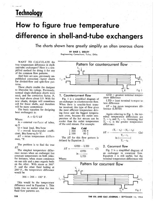
_,,_.. 1'.)'Technology<strong>How</strong> <strong>to</strong> figure true temperaturedifference <strong>in</strong> shell ..<strong>and</strong>-tube exc;hangersThe charts shown here greatly simplify al'l often onerous choreBY DALE L. GULLEYEng<strong>in</strong>eer<strong>in</strong>g Consultant, Tulsa, Okla.WANT TO CALCULATE thetrue temperature difference <strong>in</strong> shell<strong>and</strong>-tubeexchangers? Here is a simplifiedmethod fDr do<strong>in</strong>g it for anyof the common flDW patterns.And here are new, previDusly unpublishedcDrrectiDn - fac<strong>to</strong>r chartsfDr divided-flow <strong>and</strong> split-flow patterns.'These charts enable the designer<strong>to</strong> liberalize his, rat<strong>in</strong>gs. PreviDusly,normal s<strong>in</strong>gle-sheIl-pass charts, wereused, <strong>and</strong> the cDrrection fac<strong>to</strong>r, F,was kept above about 0.9. With thenew charts" designs will sDmetimescall for fewer' shells, <strong>and</strong> therefDrewill be mOore eCDnomical.The basic equatiDn for design<strong>in</strong>gheat exchangers, is:A = Q/U ATWhere:A = external surface Df tubes,sq ftQ = heat lDad, Btu/hourU = Dverall heat-transfer coeffiCient' Btu/hDur-sq ft- of.AT =, mean temperature d iffe renee, OF.The problem is <strong>to</strong> f<strong>in</strong>d the trueAT.The simplest temperature differenceDCCurs when an exchanger hasconstant temperature Dn both sides:for <strong>in</strong>stance, when steam cDndensesDn one side <strong>and</strong> a pure organk boilson the oth.er. With steam at 366 0F. <strong>and</strong> the Dther fluid bDil<strong>in</strong>g at266 0 P., the temperature differencewould be366 - 266 = 100 0 F.This wDuld be the temperaturedifference used <strong>in</strong> EquatiDn 1. Thisholds true no. matter what the two.fluid flow:patterns are.108t 2 .....Pattern for countercurrent flowTIt1. Countercurrent flowFig. 1 is a simplified diagram Oofan exchanger <strong>in</strong> CDuntercurrent flDW.When there is sensible-heat transfer<strong>in</strong>vDlved, this type Df flow givesthe mDst efficient temperature driv<strong>in</strong>gforce <strong>and</strong>, the biggest temperaturecrDSS, because the Dutlet temperatureof the hot stream can becODler than the outlet temperatureof the cold stream. For example:Hot Cold1200 150 i100 80The AT for this flow pattern isdef<strong>in</strong>ed by Equation 2:GTD -LTDAT=----- (2)'GTDIn-LTDWhere:--t 1Fig. 1GtD = greatest term<strong>in</strong>al temperaturedifferenceLTD = least term<strong>in</strong>al tern per ature differenceAT = lOog mean temperature difference(LMTD)Aga<strong>in</strong> referr<strong>in</strong>g tOo Fig. 1, the term<strong>in</strong>altemperature differences areT 1 - t2 <strong>and</strong> T2 - t 1 . Assum<strong>in</strong>g thatT 2 - t1 is the greater temperaturedifference:(T 2 - t 1 ) - (T 1 - t 2 )AT = -------- (2a)T2 - t1In(--T1 -t22. Cocurrent flowFig. 2 is a simplified diagram ofan exchanger <strong>in</strong> cocurrent flow.Equation 2 is still useful, but theterm<strong>in</strong>al temperature differences willPattern for cocurrent flow--t 2Fig. 2THE OIL AND GAS JOURNAL • SEPTEMBER 14, 1964
e different. For example, one difference will be T 1 - t 1 , <strong>and</strong> the Pattern for one-shell pass; two-tube pass other will be T 2 - t2' t 2This type 'Of flDW pattern is sel f r- ...., i T1dDm used. It is not very effiCfent<strong>and</strong> therefore -will not cDol a givenfluid as. much as the CDuntercurrentflDW will. The hot 'Outlet temperaturecan 'Only approach the cold'Outlet; it cannot crDSS it.But use can be made of this <strong>in</strong>abilitytD cross temperatures. Forexample, <strong>in</strong> wax <strong>and</strong>. asphaltic cDolers,coeUITent flow is' used tD makesure that the sDlidificatiDn po<strong>in</strong>t willnDt be reached. If CDuntercurrentflow were used, there would be danger'Of cool<strong>in</strong>g below design whenthe exchanger is clean..9.8.7.5[;1" I I I, ,,! I+T 1 -t 1 t 2 -t 1~~IC?.~ C!C! C!1C!:Jt c .. \LC~tt~~~~~oo...o LnRood', ~tl('l'\LIllI •.t 2-t T -T1 1 2X=--.· R=-T1 = Inlet temperature shell sideT2::: Outlet temperature shell sidet1 = Inlet temperature tube sidet2::: Outlet temperature tube side;a.t 1<strong>and</strong> errDr, but a much faster chartmethod is cDmmDnly used. Thischart method is based on apply<strong>in</strong>gaCDrrectiDn factDr tD the log-me antemperaturedifference. Then, thetrue temperature difference for thisflDW pattern will be:LlTc = LMTD (F) (3)Where LMTD is def<strong>in</strong>ed byEquatiDn 2F = cDrrectiDn factDrIf there is. CDnstant temperature'On either side; F will be 1.0.Fig. 4 is the LMTD cDrrectionfactDr fDr a 'One-shell pass, two-ormoretube-pass exchanger. SeveralpublicatiDns I 2 3 give cDrr~ctiDn-factDrcurves fDr one tD six shells <strong>in</strong>series. <strong>and</strong> even number of tubepasses.TD use the correctiDn curves it is_i\~_ ..Q~c:i~~ --'••••\ • ......-.~ .~\..... ~~-~~~~~r...::..,T2 + Fig. 3necessary tD calculate two dimensiDnlessparameters. The parameter'On the curves is called R <strong>and</strong> isequal <strong>to</strong>:T 1 -T 2 WCR = Dr -- (4)t2 -t 1weWhere:wc = heat capacity of tube fluid,Btu/OF.we = heat capacity 'Of shell fluid,Btu/OF.The variable 'On the abscissa iscalled X <strong>and</strong> is def<strong>in</strong>ed by:t2 -t1x = -----"-'-''---'-- (5)T 2 -t 1As shown <strong>in</strong> Fig. 4, at high valuesof R it is difficult tD read F accurately.TD 'Overcome this prDblem,the parameters 'Of R <strong>and</strong> X can beredef<strong>in</strong>ed:b,~'5:.f).~'l,. '1,\,MTD correction fac<strong>to</strong>rs 1 shell pass 2 or more tube passes '"" Fig. 4.1 .2 .3 .4 .5 .6xTHE OIL AND GAS JOURNAL • SEPTEMBER 14, 1964.7 .8 .9 1.0109
o-:,)smallest temperature rangeWhen R = 1, Equations 6 <strong>and</strong> 7 break down, <strong>and</strong> Equations 6a <strong>and</strong>R= ~~ 7 a should be used:greatest temperature rangeXgreatest temperature range X n - 2n = (6a)X =(Sa)Tl~hIt follows that R will always beX n - 2ny'2 (----'----1 or less, <strong>and</strong> that the curves will 1 - X n - 2nalways have a relatively flat slope. F n - 2n = (7a)For example, when the shell fluid (2/Xn-2n~ - 1 - R + y'R2 + 1cools from 190 0 <strong>to</strong> 90 0 <strong>and</strong> the In [----------tube-side fluid heats from 80 0 <strong>to</strong> (2/X n - 2n) ....,. 1 - R - y'R2 + 190 0 • Us<strong>in</strong>g Equations 4 <strong>and</strong> 5:Where n = number of shell passes.Whenever there is a temperature190 - 90 cross <strong>in</strong> one exchanger, the thermalR = = 10 Use Equation 6 <strong>to</strong> calculate Xdesign should be checked very care90 - 80 for the desired number of shells <strong>in</strong>fully. (This occurs at a correctionseries. Then use this value <strong>in</strong> Equafac<strong>to</strong>rof approximately 0.8, or90 - 80 tion 7 <strong>to</strong> obta<strong>in</strong> F.when the correction fac<strong>to</strong>r is lessX == = 0.091 Suppose it is desired <strong>to</strong> f<strong>in</strong>d the190 - 80 than 0.8 with shell passes <strong>in</strong> series.)MTD correction fac<strong>to</strong>r for the folThis should be done for two realow<strong>in</strong>gtemperature conditions:A slight misread<strong>in</strong>g of X cansons:make an appreciable difference <strong>in</strong>Hot' Cold 1. It may be more economical <strong>to</strong>F. But by us<strong>in</strong>g Equations 4a <strong>and</strong>use more shells <strong>in</strong> series, especially410Sa we f<strong>in</strong>d:404 i if the units are made of an expen1400 204 Isive alloy.90 - 80 2. 'The exchanger may not work10 200R = = 0.1 as well as it was designed for. At190 - 90 R = 10/200 = 0.05 close temperature. approaches theMTD correction fac<strong>to</strong>rs tend <strong>to</strong>190 - 90 X =200/206 = 0.971 break down at low values of F.X = = 0.91 Very seldom are three tube passes190 - 80Us<strong>in</strong>g Equation 6 <strong>and</strong> three shells<strong>in</strong> series as an example, (or a larger odd number) used.Now, the correct value of 0.826 is easily read from Fig. 4. '1 - 0.05 X 0.9711 - ( )1/Equations 4a <strong>and</strong> Sa should only31 - 0.971be used with the normal one-shellX 3-6 = = 0.70pass <strong>and</strong> even number of tube passes. 1- 0.05 x 0.971They are <strong>in</strong>adequate for divided 0.05 - ( )1 /3flow or split flow. In this latter type 1 - 0.971of flow pattern the relationship R =we/We is violated.Then, from Equation 7,Sometimes R will be outside thenormal range of chart values, <strong>and</strong>y'(0.05)2 + 1 1 - 0.70more than six shell passes <strong>in</strong> seriesIn (-----0.05 - 1 1 - 0.05 x 0.70will be needed. In these cases useF 3-6 = = 0.988the follOw<strong>in</strong>g equations, based on(2/0.70) - 1 - 0.05 + y'(0.05)2 + 1work by Bowman: 4 In [1-RX(2/0.70) - 1 - 0.05 - y'(0.05)2 + 11- ( - - ) l/n "Manufactur<strong>in</strong>g difficulties m a k eI-XTo calculate the corrected MTDevery type but a fixed-tube-sheetX n - 2n =(6) by computer, block diagram<strong>in</strong>g <strong>in</strong>unitundesirable.corporat<strong>in</strong>g Equations 6 <strong>and</strong> 7 canFischer6 derived a trial-<strong>and</strong>-errorR-( be found. 5I-Xsolution for a one-sheIl-pass". threetUbe-passunit. One tube pass is <strong>in</strong>y'R2+1 1 - X n - 2n cocurrent flow <strong>and</strong> the other twoIn (-----are <strong>in</strong> countercurrent flow. S<strong>in</strong>ceR-1 1 - R X n - 2n more than one-half of the tubeFn- 2n = (7) passes are <strong>in</strong> countercurrent flow,(2/X n - 2n) - 1 - R + y'IP + 1 the correction fac<strong>to</strong>r is higher than~[ ] <strong>in</strong> an even-tube-pass unit. A correc(2/Xn- 2n) - 1 - R - y'R2 + 1 . tion-fac<strong>to</strong>r chart for one shell is110 THE OIL AND GAS JOURNAL • SEPTEMBER 14, 1964
2. A vapor belt or other type ofTwo-shell pass with long baffleenlarger.te 2If the first type is used, then Fig.6a is better. S<strong>in</strong>ce there are twotsmaller nozzles enter<strong>in</strong>g rather thanone big one, fewer tubes will be re1-,----- moved for imp<strong>in</strong>gement protection.Thus, <strong>in</strong> this arrangement there are~more tubes <strong>in</strong> a given size shell.If the flow is reversed (flow<strong>in</strong>gtFig; :5up) as <strong>in</strong> a thermosiphon reboiler,t 1where it is desired <strong>to</strong> remove tubesfor vapor escape area, the samegiven. For more than one shell the 5. Divided-flow, one-tube holds true.results are tabulated.passIf a vapor belt is used, then the4. Longitud<strong>in</strong>al baffle The divided - flow, s<strong>in</strong>gle - tubebetter.The number of tubes will.nozzle arrangement <strong>in</strong> Fig. 6b isSometimes when a two-shell cor pass correction fac<strong>to</strong>r is seldom usedrection (or greater) is required, it by itself, but is useful <strong>to</strong>'develop rema<strong>in</strong> the same <strong>in</strong> a given shell, 'is possible <strong>to</strong> use a longitud<strong>in</strong>al baf correction fac<strong>to</strong>rs for divided flowis.The two outlet nozzles will beno matter what the <strong>in</strong>let nozzle sizefle. This flow arrangement is illus multitube pass <strong>and</strong> split flow.trated <strong>in</strong> Fig. 5.In the past there has been some smaller than the two <strong>in</strong>let nozzlesFor four or more tube passes, a confusion about what is divided shown <strong>in</strong> Fig. 6a, when condens<strong>in</strong>g2-4 correction fac<strong>to</strong>r is used. This floW <strong>and</strong> what is split flow. This downward, <strong>and</strong> they can be placedassumes two th<strong>in</strong>gs:was resolved <strong>in</strong> the 1959 issue of closer <strong>to</strong> the tube sheets. This leaves1. There is a perfect seal be TEMA.3 TEMA refers <strong>to</strong> divided less space between the nozzle <strong>and</strong>tween the shell <strong>and</strong> the long baffle. flow as be<strong>in</strong>g shell type J. Divided the tube sheet <strong>and</strong> a more effective2. There is no conduction through flow is illustrated <strong>in</strong> Fig. 6.flow pattern is obt~ned.the long baffle. Frequently the question arises, A procedure has been developedThe effect 9f the second assump which of the nozzle arrangements for construct<strong>in</strong>g a divided-flow, onetioncan be ignored with small-shell shown <strong>in</strong> Fig. 6 should be used? The tube - pass correction - fac<strong>to</strong>r chart, 8fluid-cool<strong>in</strong>g ranges. If the cool<strong>in</strong>g answer lies ma<strong>in</strong>ly <strong>in</strong> what type of based on a method used by K. A.range is large <strong>and</strong> there is a large imp<strong>in</strong>gement protection is used. The Gardner.9temperature driv<strong>in</strong>g force across the two common types are: To develop a chart, an expressionfor X is used <strong>in</strong> terms. of Rbaffle, then baffle conduction will 1. Remov<strong>in</strong>g tubes under the noz<strong>and</strong>¢:have <strong>to</strong> be cgnsidered. Whister 7 pre zle.sents an equation for F, for two¢(2R+l)/2 -shell-two tube passes <strong>in</strong>corporat<strong>in</strong>g 1 (1 -X) (¢(2R-l)/2 - 1)baffle conduction. X= +------------------- (8)(2 R + 1) ¢(2R+l)/2 (2 R - 1) 4>(2R-l)/2If the two assumptions are valid,<strong>and</strong> there is a long baffle <strong>and</strong> twoSolv<strong>in</strong>g for X:tube passes, no MTD correction fac<strong>to</strong>r is necessary because the shell (¢(2R-l)/2 - ¢-l) (2 R - 1) + (¢(2R-l)/2 - 1) (2 R + 1) side <strong>and</strong> the tube side will be <strong>in</strong> X = ------------~---- (9)counterflow. (2R + 1) (2R 4>(2R-l)/2 - 1) --------------------------------------------Divided flowTo calculate F, a value of ¢ isassumed. Then X is calculated from~--------~-~----~ Equation 9. For a given value ofR, Equation 10 is used <strong>to</strong> f<strong>in</strong>d F:(1 - X)/(1 - RX) tl~ ---.. t 2 F = In (10) (R - 1) In 4>t 1 -: ! I I 'I' I I i:Xni , , ,(0) If it is desired <strong>to</strong> develop 'chartsfor niore than one shell pass, a formof Equation 6 can be used. Let nbe the number of shell passes <strong>in</strong>(b)series. Then:RX -1)n - 1~t2X -1= (11)Fig.6X -1)n - R.THE OIL AND GAS JOURN,AL • SEPTEMBER 14, 1964 111
....'.:,.0.1 0.2 0.4 0.5 0.6 On,e divided shell jOOne-tube pass 1$1rrrITTTTTITT Tj T lti9 t2T20.90.8O.0.70.1 0.2 0.30.4 0.5 0.6X=(t'2.- t,~(rl- 9o. o.B o.~1.0Xn <strong>and</strong> R are plotted <strong>to</strong> give themultishell-pass charts.There are two values of R thatrequire a different calculation procedure.These values are R = 0.5,or R = 1.0.When R = 0.5, Equation 9 breaksdown.Tak<strong>in</strong>g the limit of Equation9 as (R - 0.5) approaches 0, wehave:(cp - l)/cp + In cpX= (12) 2+Incp Equation 12 is used with Equation10 <strong>to</strong> give F.When R = 1.0, Equation 9 isstill used <strong>to</strong> calculate X, but Equation10 will break down when usedfor F. Tak<strong>in</strong>g the limit of Equation10:XF=(1 - X) In cp(13)Equation 9 is used with Equation13 <strong>to</strong> give F.\Vhen develop<strong>in</strong>g charts for more,than one shell, Equation 11 willalso break down. In that case, useEquation 6a <strong>to</strong> f<strong>in</strong>d the correct valueof X for plott<strong>in</strong>g F.Fig. 7 is an F chart for s<strong>in</strong>gletubepass <strong>and</strong> one divided shell.Charts for the two, three, <strong>and</strong> fourdivided shells may be obta<strong>in</strong>ed fromthe author.Develop<strong>in</strong>g these charts by h<strong>and</strong>is quite tedious, but they lend themselves<strong>to</strong> computer application verywell.A Fortran program is availablefor calculat<strong>in</strong>g F values, upon requestfrom the author.6. Divided-flow, two-tubepassA trial-<strong>and</strong>-error solution for Fhas been presented 8 <strong>to</strong> use dividedflow,one-tube pass correction:1. Assume a value for the <strong>in</strong>termediatetemperature between tubepasses. A good start<strong>in</strong>g po<strong>in</strong>t is:tb = t1 + 0.6 (t2 - t1) (14)2. Calculate the LMTD <strong>in</strong> thelower tube pass by us<strong>in</strong>g Fig. 7.3. Calculate the LMTD <strong>in</strong> theupper tu be pas s us<strong>in</strong>g Fig. -7.4. C a I cui ate the <strong>in</strong>termediatetemperature (tb)' S<strong>in</strong>ce temperaturerise <strong>in</strong> each pass is proportional <strong>to</strong>its LMTD:tb = t1 +(t2 - t1) (LMTD)L(LMTD)L + (LMTDh(15)5. If tb doesn't check the assumedvalue, start aga<strong>in</strong> us<strong>in</strong>g thelast value of tb'6. Calculate the corrected MTDby weight<strong>in</strong>g the MTD's of theupper <strong>and</strong> lower tube pass, us<strong>in</strong>gEquation 16:t2 - t1 Atm =(16) tb - t1 t2 - tb ._---+--(LMTD)L (LMTDh 7. The correction fac<strong>to</strong>r is backedout by us<strong>in</strong>g Equation 3. Example:The shell fluid cools from 200 0<strong>to</strong>120 0 F., <strong>and</strong> the tube fluid heatsup from 80 0 <strong>to</strong> 120 0 F.112 THE OIL AND GAS JOURNAL • SEPTEMBER 14, 1964
, '. I0.1 0.3 0.4 0.5 0.6 0.7 0.8 1.0I.80.90.9 110eUco ....... c:e'"5Q)1010e0.8" ~I~IIu.:..TITI.. . ita~====~j:Jtl ,0.7 T2One divided··shellTwo-tube pass.0.1 0.2 0.31. From Equation 14, tb = 80 +0.6 (40) = 104.2. LMTD <strong>in</strong> the lower tube pass:Hot fluid Cold fluid <strong>Difference</strong> 200 - 104 96 120 - 80 = 40 LMTD = 64R =3.33 X = 0.2Lltm = LMTD X F = 64 X 0.92= 58.93. LMTD <strong>in</strong> the upper tube pass:Hot fluid Cold fluid <strong>Difference</strong>200 - 120 80120 - 104 16LMTD = 39.8R=5.0X=0.167Lltm = LMTD X F =0.882 = 35.14. From Equation 15,(40) (58.9)tb = 80 +58.9 + 35.139.8 )< = 105 0.5 0.6X=(t~- tJ(r,- t 1)5. S<strong>in</strong>ce the calculated value oftb did not match the value used, usethe calculated value <strong>and</strong> go back <strong>to</strong>the start.The f<strong>in</strong>al value of tb is 105.5.6. With the f<strong>in</strong>al value of tb theMID's are:Lower Lltm = 57 <strong>and</strong> upper Lltm= 32.From Equation 16,~".' 40Lltm= = 44.525.5/57 + 14.5/327. F = 44.5/57.6 = 0.773A computer is almost a must <strong>to</strong>calculate the many different po<strong>in</strong>tsrequired for an F chart.A Fortran program can be writtenfor this type of flow. The biggestproblem <strong>in</strong> putt<strong>in</strong>g it on thecomputer is <strong>to</strong> calculate the correctionfac<strong>to</strong>r for divided-flow, onetubepass. When do<strong>in</strong>g it by h<strong>and</strong>,as <strong>in</strong> the above example, use an Fchart. S<strong>in</strong>ce the F chart' was developedby trial <strong>and</strong> error, we donot have an equation for it. There<strong>in</strong>lies the trouble.0.7 0.8 0.9 1.0Solv<strong>in</strong>g Equation .9 for cp0.80.7isn'tpossible by the usual means. Andwithout cp it is impossible <strong>to</strong> calculateF.In the computer program developedby the author, cp is found bytrial <strong>and</strong>' error. To converge on thevalue of cp, use. Equation 17 as afirst approximation:cp=2[ F/(R+O.5) (17)2 - 1.05 X (2 R + 1)After this value is calculated; usethe first derivative method of converg~nce.Fig. 8 is the F chart for one dividedshell <strong>and</strong> two tube passes.The dashed l<strong>in</strong>e extended across thechart shows when the outlet temperatureof the hot side is ~qual <strong>to</strong>the outlet temperature of the coldside. In ,_ compar<strong>in</strong>g this with thenormal one,-shell pass, the low po<strong>in</strong>tis approximately 0.8 while the dividedshell is approximately 0.775.Three F charts for divided-flow,two-tube pass, from two <strong>to</strong> fourTHE OIL AND GAS JOURNAL •SEPTEMBER . 14, 1964113
.\'........ -.....,(" tSplit flow·t. 2 t TI r -,~--I tFig. 9- f2 T2shells <strong>in</strong> series, respectively, maybe obta<strong>in</strong>ed from' the author.Split flow. At times, when a highcorrection fac<strong>to</strong>r is desired, a long. baffle will give <strong>to</strong>o much pressuredrop. In this case split flow can beused. This type of flow is shown <strong>in</strong>Fig. 9.Some of the correction - fac<strong>to</strong>rcharts already developed can beused. By analyz<strong>in</strong>g two dividedflow,one-tube passes <strong>in</strong> series, itcan be seen that it is equivalent <strong>to</strong>a split-flow-shell, two-tube passes.In like fashion, the four dividedshell,one-tube pass can be used fortwo split-flow shells <strong>in</strong> series withtwo tube passes each. If it is desired <strong>to</strong> use more splitflowshells, <strong>in</strong> series, use Equation11. Us<strong>in</strong>g the divided-flow correctionfac<strong>to</strong>rs <strong>in</strong> this manner assumeswe have the same perfect conditionslisted under longitud<strong>in</strong>al baffle.When you have split flow <strong>and</strong>four or more tube passes, then thepreviously mentioned charts obta<strong>in</strong>ablefrom' the author can be used,one for a s<strong>in</strong>gle shell, <strong>and</strong> one fortwo shells.Author Dale L. Gulley lives at2714 S. 75th E. Ave., Tulsa, Okla.References1. Kern, D. Q., "Process Heat Transfer":McGraw-Hill, 1950.2. McAdams, "Heat Transmission": Thirdedition, McGraw-Hill, 1951.3. St<strong>and</strong>ards of TEMA: Fourth edition,1959.4. Bowman, R. A., "Mean-<strong>Temperature</strong><strong>Difference</strong> Correction <strong>in</strong> Multipass Exchangers":Ind. <strong>and</strong> Engr. Chern., 28, 1936, pp.541-544.5. Gulley, D. L., "Use Computers <strong>to</strong> SelectExchangers": Petroleum Ref<strong>in</strong>er, 39,1960, pp. 149-156.6. Fischer, F. K., "Mean - <strong>Temperature</strong><strong>Difference</strong> Correction <strong>in</strong> Multipass Exchangers":Ind. <strong>and</strong> Engr. Chern., 30, 1938, pp.377-383.7. Whister, A. M., "Correction for HeatConduction Through Longitud<strong>in</strong>al Baffle ofHeat Exchanger": Trans. ASME, 69, 1947,pp. 683-685.8. Gulley, D. L., "Make This CorrectionFac<strong>to</strong>r Chart <strong>to</strong>· F<strong>in</strong>d Divided Flow ExchangerMTD":Petro/Chem Eng<strong>in</strong>eer, July1962, pp. 143-145.. 9. Gardner, K. A., "Mean <strong>Temperature</strong><strong>Difference</strong> <strong>in</strong> Multipass Exchangers": Ind.<strong>and</strong> Engr. Chern., 33, 1941, pp. 1495-1500.AcknowledgmentTo Western Supply Co. for use of itselectronic computer <strong>and</strong> <strong>to</strong> Paul Buthodfor mathematical assistance.BOOKSGUIDE DU PETROLE ET DELA PETROCHIMIE (Petroleum <strong>and</strong>Petrochemical Guide). 1964 annualedition. Published by Editions O. Lesourd,252 Faubourg Sa<strong>in</strong>t-Honore,Paris 8, France. Price 100 francs.(Franco 104.20 francs.)The 34th annual edition of this outst<strong>and</strong><strong>in</strong>gdirec<strong>to</strong>ry came off the press<strong>in</strong> Paris <strong>in</strong> May. It conta<strong>in</strong>s more than1,000 pages of names <strong>and</strong> addressesof oil, petrochemical, <strong>and</strong> service companies,plus phone numbers, personnel,company relationships, <strong>and</strong> otherdata.Here, briefly, is an outl<strong>in</strong>e of thisuseful book:Part 1. Oil. This list<strong>in</strong>g gives detailson adm<strong>in</strong>istrative <strong>and</strong> professionaloil groups, <strong>in</strong>clud<strong>in</strong>g memberships.It lists French oil companiesaccord<strong>in</strong>g <strong>to</strong> their functions, i.e., exploration<strong>and</strong> production; transportation<strong>and</strong> s<strong>to</strong>rage; eng<strong>in</strong>eer<strong>in</strong>g, ref<strong>in</strong><strong>in</strong>g,import<strong>in</strong>g, <strong>and</strong> distribution; lube oils;<strong>and</strong> natural gas <strong>and</strong> products.Part 2. Petrochemicals <strong>and</strong> plasticmaterials. Here you will f<strong>in</strong>d <strong>in</strong>formationon various French petrochemicalcompanies <strong>and</strong> organizations, <strong>in</strong>clud<strong>in</strong>gnames <strong>and</strong> titles of companyofficials.Part 3. Oil <strong>and</strong> petrochemical market.This <strong>in</strong>Cludes names of companies<strong>and</strong> other <strong>in</strong>formation on firmsdo<strong>in</strong>g bus<strong>in</strong>ess <strong>in</strong> the Common Market<strong>and</strong> the OECD countries, as wellas North Africa :;tnd the Middle East.Part 4. . This <strong>in</strong>cludes a general<strong>in</strong>dex (Petrole-Chimie-Telephone) ofoil, chemical, <strong>and</strong> supply <strong>and</strong> equipmentcompanies. The list<strong>in</strong>gs <strong>in</strong>cludenames of adm<strong>in</strong>istra<strong>to</strong>rs, direc<strong>to</strong>rs,heads of departments, <strong>and</strong> technicalpersonnel. This section <strong>in</strong>volves morethan 3,000 namees of oil personnel.In addition <strong>to</strong> the basic guide, youmay subscribe <strong>to</strong> the monthly supplementswhich keep the book up <strong>to</strong> date.Price of the monthly supplements is20 francs per. year.FEDERAL TAX TREATMENTOF INCOME FROM OIL ANDGAS. By Stephen L. McDonald.Brook<strong>in</strong>gs Institution, 1775 MassachusettsAve. N.W., Wash<strong>in</strong>g<strong>to</strong>n, D.C.163 pages. Paper $2, cloth $3.50.This is a summary of a symposiumon oil-depletion tax provisions heldby a group of professional economistsat Brook<strong>in</strong>g Institution. Bulk of thevolume is a background paper prepared<strong>in</strong> advance by Stephen L. McDonald of University of Texas. Therema<strong>in</strong>der is a summary of conferencediscussion.The volume is perhaps the best recentstatement of views of economistson percentage depletion <strong>and</strong> expens<strong>in</strong>gof <strong>in</strong>tangible drill<strong>in</strong>g costs. It outl<strong>in</strong>esthe his<strong>to</strong>ry of these provisions<strong>and</strong> describes their application <strong>in</strong> variousproduc<strong>in</strong>g situations <strong>and</strong> their effectson the petroleum <strong>in</strong>dustry.It discusses the theories, justifications'<strong>and</strong> criticisms of these tax provisionsfrom the st<strong>and</strong>po<strong>in</strong>t of differentialrisk, the wast<strong>in</strong>g asset ofpetroleum resources, conservation, nationalsecurity, <strong>and</strong> capital-ga<strong>in</strong>s taxation.Conclusions are that reduction ofpercentage rates would tend <strong>to</strong> raiseprices <strong>in</strong> the long run, but this mightbe offset by competition, greater- efficiency,<strong>and</strong> reduction <strong>in</strong> rental bonuses.Increased revenue <strong>to</strong> the U.S.Treasury could vary from a very li~t1e<strong>to</strong> $2 billion annually' depend<strong>in</strong>g onhow the <strong>in</strong>dustry operated.The book notes that it considerseconomic aspects only, not other fac<strong>to</strong>rs<strong>in</strong> public policy.NEW GUIDE TO MORE EFFECTIVE WRITING IN BUSINESSAND INDUSTRY. By Robert Gunn<strong>in</strong>g.Published by Industrial EducationInstitute, 221 Columbus Ave.,Bos<strong>to</strong>n 02116. 358 pp. $12.50.This book gives you ideas <strong>to</strong> improveeveryth<strong>in</strong>g you write.These are techniques <strong>and</strong> formulasyou can app~y at once <strong>to</strong> every writ<strong>in</strong>gproblem.Step-by-step guidance is given fororganiz<strong>in</strong>g thoughts <strong>and</strong> putt<strong>in</strong>g themdown on paper, gett<strong>in</strong>g ideas across,writ<strong>in</strong>g <strong>to</strong> get the action you want,how <strong>to</strong> do a better job of writ<strong>in</strong>g,<strong>and</strong> how <strong>to</strong> write faster.Note: The Oil <strong>and</strong> Gas Journal ma<strong>in</strong>ta<strong>in</strong>sa book department. Write <strong>to</strong> the Book Department,PO Box 1260, Tulsa, Okla. 74101,for copies of the book list. Often books reviewedhere may be purchased from thissource.114 THE OIL AND GAS JOURNAL • SEPTEMBER 14, 1964