Harvester User Manual - Without Tire (New Models) (PDF)
Harvester User Manual - Without Tire (New Models) (PDF)
Harvester User Manual - Without Tire (New Models) (PDF)

You also want an ePaper? Increase the reach of your titles
YUMPU automatically turns print PDFs into web optimized ePapers that Google loves.
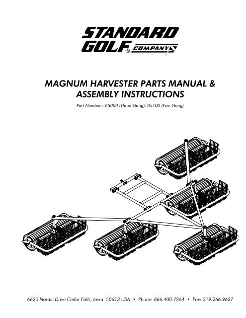
MAGNUM HARVESTER SPECIFICATIONSModel Number # GangsWeight“A’ “B” “C” “D” “E” “F” “G”80000 3 9.0 ft 5.8 ft 7.8 ft N/A N/A 4.50 in 21.43 in 310 lbs80100 5 9.0 ft 5.8 ft 7.8 ft 9.0 ft 15.0 ft 4.50 in 21.43 in 460 lbsGF
MAGNUM HARVESTER WARRANTYStandard Golf Company warrants its products to be free from defects in materials and workmanship within aperiod of one year from the date of purchase. Standard Golf’s sole responsibility under this warranty shall beto repair, replace, or refund to its Distributor the price of the defective product or component. All such repairs,refunds and replacements are subject to such rules, terms and conditions as Standard Golf may promulgate fromtime to time.MAGNUM HARVESTER MAINTENANCE PROCEDURESDaily•Check for evidence of physical damage and loose hardware. Replace and/or repair as necessary.Monthly•Check all hinge points for lubrication, grease as needed. (see below for grease zerk locations)Zerk locations are shown below. Zerk locations are identical on all gangs, making 26total zerks for a five gang, and 16 total for a three gang.
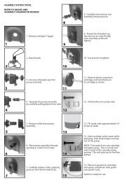
MAGNUM HARVESTER ASSEMBLY INSTRUCTIONSPictures and instructions are written for a five gangassembly. Note that not all pictures and instructionsapply to three gang assemblies.1. Remove all parts from the box and place on theground in a large open area as shown in diagram tothe right. Be sure that the front gang (with the FrontGang Pin - See #3) is placed in the front position.The remaining rear gangs are identical and do notneed to be placed in any specific order.2. Make sure that the right and left arm assembliesare on the correct sides. The correct positions areshown in the diagram to the right. (five gang only)3. On the front gang (with Front Gang Pin) assembly,remove the pin and pin collar from the shaft,leaving the spring as shown in the diagram.4. Slide the A-Frame over the shaft and spring. Youmay need to push down on the assembly to getthe required space at the top of the shaft to insertthe pin collar and pin. Insert pin collar and pin asshown in the diagram.5. With the front gang attached, move to eitherof the two gangs located directly behind the frontgang.
6. Remove the pin collar, and pin from the shaft onthe next two gangs behind the front gang.7. Slide A-Frame onto shaft. Then attach the pincollar with the pin as shown. Repeat for each of thetwo gangs behind the front gang.8. With three gangs now attached, now move to thearm assemblies.(five gang only)9. Remove pin from the arm assembly and attachthe arm to the A-Frame as shown, then re-insert pin.Repeat this process for each arm assembly.(five gang only)10. Remove pin collar and pin from the rear gang.Slide arm assembly onto shaft, and replace pincollar, and pin to the top of the shaft as shown.Repeat for remaining gang.(five gang only)