Super X3 Milling Machine - Travers Tool Company, Inc.
Super X3 Milling Machine - Travers Tool Company, Inc.
Super X3 Milling Machine - Travers Tool Company, Inc.
Create successful ePaper yourself
Turn your PDF publications into a flip-book with our unique Google optimized e-Paper software.
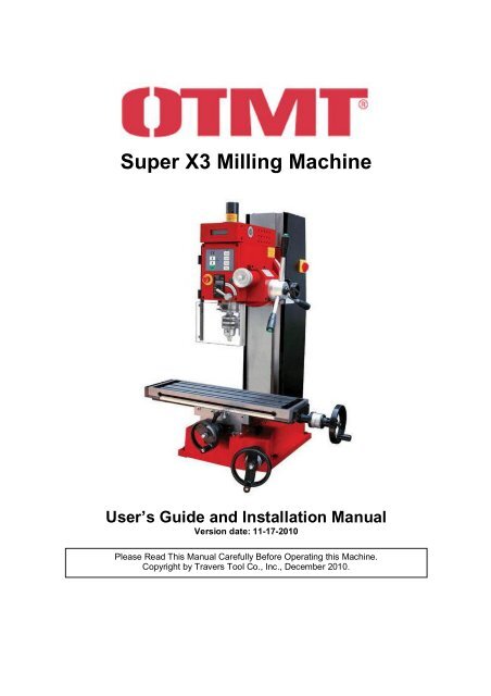
<strong>Super</strong> <strong>X3</strong> <strong>Milling</strong> <strong>Machine</strong>User’s Guide and Installation ManualVersion date: 11-17-2010Please Read This Manual Carefully Before Operating this <strong>Machine</strong>.Copyright by <strong>Travers</strong> <strong>Tool</strong> Co., <strong>Inc</strong>., December 2010.
Table of ContentsIMPORTANT SAFETY INSTRUCTIONS........................................................................3Parts of the Mill.............................................................................................................4Welcome........................................................................................................................5User Manual................................................................................................................5Capabilities of the Mill.................................................................................................5Setting up the Mill.........................................................................................................6Electrical Requirements..............................................................................................6Lifting the Mill..............................................................................................................6Bench Mounting..........................................................................................................6<strong>Machine</strong> Cleanup........................................................................................................7Operating Controls and Features................................................................................8Table Motion Controls.................................................................................................8Locking Levers............................................................................................................8Vertical Motion Control................................................................................................8Quill Digital Readout...................................................................................................9Electronic Controls.......................................................................................................9Control Panel Buttons.................................................................................................9Emergency Stop Button............................................................................................10<strong>Tool</strong>ing and Accessories............................................................................................11Drill Sets....................................................................................................................11End Mills...................................................................................................................11Securing Work to the Table.......................................................................................12Clamping Sets...........................................................................................................12<strong>Milling</strong> Vises..............................................................................................................12Parallels....................................................................................................................12Eye Protection...........................................................................................................13Basic <strong>Milling</strong> and Drilling............................................................................................14Initial Checkout..........................................................................................................14Safety Checks...........................................................................................................14Drilling.......................................................................................................................15<strong>Milling</strong>........................................................................................................................16Advanced Features.....................................................................................................18Tilting Head Feature..................................................................................................18Power Tapping Feature.............................................................................................18Maintenance................................................................................................................20Periodic Lubrication...................................................................................................20Ball-Race Lubrication................................................................................................20Z-Axis Drive Gears....................................................................................................20Bare Metal Surfaces..................................................................................................20Adjusting the Gibs.....................................................................................................20Appendices .................................................................................................................22Appendix A................................................................................................................22Appendix B – Parts Diagrams...................................................................................23Appendix C – Parts List.............................................................................................26Appendix D – Electrical Block Diagram.....................................................................272
IMPORTANT SAFETY INSTRUCTIONSCommon sense and caution are factors which cannot be built into any product. Thesefactors must be supplied by the operator.PLEASE REMEMBER:1. When using electric tools, machines or equipment, basic safety precautionsshould always be followed to reduce the risk of fire, electric shock, and personalinjury.2. Keep work area clean. Cluttered areas invite injuries.3. Consider work area conditions. Don not use machines or power tools in damp,wet or poorly lit locations. Don not expose equipment to rain, keep work areaswell lit. do not use tools in the presence of flammable gases or liquid.4. Keep children away; all children should be kept away from the work area.5. Guard against electric shock. Prevent body contact with grounded surfaces suchas pipes, radiators, ranges and refrigerator enclosures.6. Stay alert. Never operate a power tool if you are tired.7. Do not operate the product if under the influence of alcohol or drugs. Readwarning labels on prescriptions to determine if your judgment or reflexes mightbe impaired.8. Do not wear loose clothing or jewelry as they can be caught in moving parts.9. Wear restrictive hair covering to contain long hair.10. Use eye and ear protection. Always wear.11. Keep proper footing and balance at all times.12. Do not reach over or across running machines.Before operations1. Be sure the power switch is OFF when not in use and before plugging in.2. Do not attempt to use inappropriate attachments in an attempt to exceed thetool’s capacity.3. Check for damaged parts before using any tool, and part that appears damagedshould be carefully checked to determine that it will operate properly and performits intended function.4. Check for alignment and binding of all moving parts, broken parts or mountingfixtures and any other condition that may affect proper operation. Any part that isdamaged should be properly repaired or replaced by a qualified technician.5. Do not use the tool if any switch does not turn off properly.Operation1. Never force the tool or attachment to do the work of a larger industrial tool. It isdesigned to do the job better and more safely at the rate for which it wasintended.2. Do not carry the tool by its power cord.3. Always unplug the cord by the plug. Never yank the cord out of the wall.4. Always turn off the machine before unplugging.3
Parts of the MillBefore operating the mill, please study the diagram below to become familiar with thecomponents and operating controls.4
WelcomeCongratulations on selecting the OTMT <strong>Super</strong> <strong>X3</strong><strong>Milling</strong> <strong>Machine</strong>. You have chosen a precisionmachine tool that can perform a wide range ofcomplex and precise milling operations. With propermaintenance and care, it will provide many years ofservice. Should you have any questions regardingthe operation of your mill, please contact <strong>Travers</strong>Technical Support for assistance.Note: A PDF version of this manual, available onthe <strong>Super</strong> <strong>X3</strong> page at <strong>Travers</strong>.com, has direct linksto suggested accessories.Technical Support(1-800-234-9985, press 4)Fax: 718-661-5637email: tech@travers.comUser ManualThe purpose of this manual is to familiarize theoperator with the installation and controls of themachine and basic drilling and milling procedures. Tobecome proficient in using the mill, the operatorshould seek in-depth training using reference books,resources available on the internet, training coursesat community technical schools or from an operatoralready skilled in the use of a similar milling machine.Capabilities of the MillTogether with a lathe, a vertical milling machine isone of the essential tools in the machine shop. It canproduce a wide variety of precision shapes and formsin most metals, including steel, brass, aluminum andeven tough metals such as stainless steel and bronze.It can also work effectively with many plastics andengineering materials such as Teflon (PTFE), Delrinand Nylon. The mill also will serve very effectively asa precision drill press.A vertical mill such as the <strong>Super</strong> <strong>X3</strong> is capable of awide variety of operations where the holdingmechanisms, cutting tools and materials beingmachined will vary depending on the requirements ofa particular job. With a selection of accessoriesavailable from <strong>Travers</strong>, you can increase the range ofwork that your mill can perform.5
Setting up the MillThe <strong>Super</strong> <strong>X3</strong> mill should be located in a well-lightedand well-ventilated area free from excessive humidityor moisture that could cause rusting of the precisionmetal surfaces or tooling.Electrical RequirementsLifting the MillThe <strong>Super</strong> <strong>X3</strong> mill weighs approximately 365 lbs.(165 kg.) and must be mounted on a strong tableor bench capable of supporting 400 lbs. or more. Ashop crane with a nylon lifting strap or othersuitable lifting apparatus should be used to safelylift the machine onto the table or bench.The <strong>Super</strong> <strong>X3</strong> mill configured for U.S. operation usesstandard 120V AC 60-cycle single-phase power andhas a peak current demand of 12 amps. While a 15-amp circuit may be sufficient for powering the mill, a20-amp circuit is recommended. The circuit must notbe shared with other high-current devices, such as anair compressor, window air conditioner or coffee pot,that may be operating, or switch on, while the mill is inuse. Low current devices, such as a work lamp, mayshare the same circuit as the mill.A plug-in power failure emergency light that willautomatically turn on in the event of a power failure ortripping of an overloaded circuit breaker isrecommended for safety. In the event that power tothe mill, or workspace lighting, should be interruptedwhile the mill is in use, the emergency light will enablethe operator to safely turn off the power switch to themill and move away from the mill until power isrestored. Suitable lights are available at mosthardware and home-supply stores.Care should be taken to ensure a safe work area withelectrical wiring and grounding approved by localelectrical codes. The mill uses a three-prong electricalplug to protect the operator from risk of shock orelectrocution. The mill must be plugged into aproperly grounded outlet to ensure safe operation. Donot attempt to modify the plug to fit a 2-prong outlet orextension cord by removing the ground conductor orby using an adaptor. Doing so may result in shock orelectrocution.If it is necessary to plug the mill into an extension cord,the extension cord must have a properly functioning3-prong electrical ground plug and outlet, plugged intoa properly grounded 3-prong wall outlet. Theextension cord must have at least 15 Amps of currentcarryingcapacity to avoid overheating the cord, whichcould cause a risk of fire. A cord rated for 20 Amps ormore is recommended. In no case should the lengthof the extension cord exceed 20 feet.6Shop crane (Item # 96-004-166)If necessary, the head and table can be removedso that mill can be lifted in three parts:1. Base and column2. Head3. TableThese components are still quite heavy and twoworkers should work together to lift them. Properlifting techniques (e.g. bend at the knees, not atthe back) should be used to minimize any risk ofpersonal injury. Consult the Internet for informationon proper lifting techniques.Bench MountingAdjustable metal feet are provided which can bescrewed into the base of the mill and adjustedindividually to level the mill. Alternatively, the millmay be bolted directly to the table or bench top.Metal washers or shims may be used, as needed,to ensure that the mill table is level. A carpentersor machinists level should be used to verify thatthe mill table is level.Plywood or Medium Density Fiberboard (MDF)panels cut to size may be used under the base ofthe mill to provide additional clearance betweenthe handwheels from the bench top.Sufficient clearance must be provided on bothsides of the machine to allow for movement of thetable through its full range of motion and for
turning the handwheels that move the table. Spacemust also be provided to the left side of the millingtable for the power feed option if it will be installed.<strong>Machine</strong> CleanupThe milling machine is protected from rust duringshipping by a waxy red grease that must beremoved before putting the machine to use. This isbest done using disposable shop rags and paintbrushes together with a solvent such as keroseneor WD-40. Avoid solvents such as paint thinnerthat may damage the painted surfaces of the mill,and highly volatile solvents such as acetone thatpresent a fire and inhalation hazard.Dimensions of Basein millimetersGood ventilation must be provided when solventsare used and care must be taken to avoid openflames, smoking materials or electrical sparks thatcould ignite solvent fumes. Care should be takento clean the shipping grease from all moving parts,including parts that may be hidden from view, suchas leadscrews under the table.7
Operating Controls and FeaturesTable Motion Controlslever for that axis. The locking levers are spring-loadedso that the resting position of the lever may set to aconvenient orientation by pulling out on the lever,turning it, then releasing it.For many milling operations the workpiece is held ina vise or is clamped to the table and moved into therotating cutting tool by turning the table handwheels.The lengthwise motion of the table is referred to asthe X-axis, the front-to-back motion as the Y-axis andthe up and down motion of the head as the Z-axis.The table can be moved a measured distance byobserving the graduated collars on each handwheeland by counting full rotations of the handwheels. Thegraduated collars on the X- and Y-axis handwheelscan be set to a zero reference point by holding thehandwheel steady while turning the graduated collarto zero.Exploded view of locking leverVertical Motion ControlThe cutting tool can be moved in the Z- or vertical axisby turning the Z-axis handwheel, located near the frontright corner of the mill, to raise or lower the head. Thecutting tool also can be raised or lowered using eitherthe 3-spoke lever or the fine-feed handwheel to movethe spindle.When advancing the spindle using the 3-spokehandwheel, the mill functions as a high precision,heavy-duty drill press.Setting dial to zeroThe X-axis handwheel may be disengaged from theleadscrew by pulling outward on the handwheel. Thisfeature is used mainly in conjunction with the optionalpower feed to reduce the risk of the handwheelstriking an object while turning under power.CAUTION: Do not release the 3-spoke handwheel andlet it snap back under spring pressure. Control theretraction by winding the spindle back by hand.For precise control of the cutting depth for millingoperations either the Z-axis handwheel or the quill finefeedhandwheel may be used. The fine-feedhandwheel is engaged by turning the fine-feed lockhandle (#21 on the parts diagram) located at the centerof the 3-spoke handwheel. Turning this knob clockwiseengages the fine-feed; turning it counter-clockwisedisengages the fine-feed.Disengaging the handwheelLocking LeversFor maximum accuracy, the axes that are not beingmoved should be locked in place using the lockingFine-feed handwheel8
When the fine-feed handwheel has been used to setthe quill to the desired cutting depth, the quill shouldbe locked in position using the quill locking lever toensure maximum rigidity of the cutting tool.Control Panel ButtonsFor safety, a polycarbonate plastic shield with anelectrical interlock must be opened to access thespindle while changing tools. The interlock preventsthe spindle from being powered on while the safetyshield is in the open position.Quill Digital ReadoutThe depth of the quill feed can be read directly fromthe digital readout for both drilling and millingoperations. The digital readout control buttons areOFF/ON – toggles the display on or offMm/<strong>Inc</strong>h – toggles the display between inchand millimeter unitsZERO – sets the readout to zero at thecurrent quill positionControl buttonsLocated on the control box on the left side of the headare the electronic operating controls:Ø - <strong>Inc</strong>rease spindle RPM speedŒ- decrease spindle RPM speedStart – start the spindle motorTapping – switch tapping feature on or offForward – set spindle to forward rotationaldirectionReverse – set spindle to reverse rotationaldirectionStop – stop the spindle motorAfter insuring that the cutting tool is clear of theworkpiece and that the spindle safety shield is securedin the fully closed position, press the green STARTbutton to start the spindle rotation.Quill extension digital readout (DRO)In practice, the digital readout usually is zeroed whenthe tip of the cutting tool is just touching the topsurface of the workpiece.The first time that the START button is pressed afterturning on the power to the mill, of after resetting theEmergency Stop button, the spindle will begin turningat its slowest speed, about 100 RPM. The currentspindle rotational speed is displayed on the digitaldisplay above the electronic control panel.Electronic ControlsThe main power switch for the mill is located on theright side of the column. The switch should be turnedto the OFF position when the mill will not be used forperiods of several hours or more. When the powerswitch is in the ON position, the green pilot lampabove the spindle lock lever is illuminated.Spindle-speed tachometerTo increase the speed of spindle rotation, depress andhold down the Up-arrow button. To decrease spindlespeed, depress and hold down the Down-arrow button.Small incremental changes to the spindle speed maybe made by momentarily pressing the Up- or Down-9
arrow buttons. To stop the spindle rotation, press theSTOP button.Emergency Stop ButtonLocated below the START button, the redEmergency Stop button is used to quickly stop thespindle in the event of an emergency, such as aworkpiece working loose from the vise.Emergency Stop buttonPressing the Emergency Stop button firmly with theheel of the hand will bring the spindle to a stop andkeep the mill from restarting until the EmergencyStop button is reset by rotating the knurled rim of thebutton in a clockwise direction. Pressing the STARTbutton, or any other control on the panel, will have noeffect until the Emergency Stop button is reset. Whenthe Emergency Stop button is reset, the spindlespeed will also be reset to the minimum speed ofabout 100 RPM.10
Securing Work to the TableWhen working with the mill, the workpiece may beheld in a milling vise, a specialized holder such as arotary table or may be clamped directly to the surfaceof the table. Care must be taken that both theworkpiece and the holding device(s) are secured bybolts and T-nuts so that they do not move due to thecutting force of the mill.Clamping SetsFor convenience in positioning work anywhere on thetable surface, slots run the length of the table to beused with T-nuts. T-nuts are special nuts, with across-section in the shape of the letter ‘T’ that can bepositioned along the slots. They can be purchasedindividually but usually are purchased as part of aclamping set.past the bottom of the T-nut or it may apply force to thetable casting as it is tightened and crack the T-slot.Excessive force must not be applied when tightening T-nuts; just enough force to securely hold the work inplace against the cutting forces of the mill.<strong>Milling</strong> VisesA heavy milling vise often is the most convenientmeans for securing work to the mill table. <strong>Milling</strong> visesare available in various configurations suited todifferent work requirements. They are manufactured toexacting standards to ensure that the work is heldparallel and square to the mill table.<strong>Milling</strong> vise with rotating base.(Item # 61-204-304)ParallelsT-nutThe clamping set includes several T-nuts as well asan assortment of varying length rods threaded onboth ends, stackable spacers, clamps and clampingbolts. With such a set, a wide variety of clampingconfigurations can be devised to clamp work ofvarying shapes and sizes securely to the mill table.Parallels are used to support work when clamping it ina milling vise. They serve to raise the top surface of theworkpiece above the top edges of the milling vise jawsso that the milling cutter will not strike the vise jaws.Parallels typically are sold in sets of matching pairs in aseries of heights, such as ½” through 1-1/2” inincrements of 1/8” and in thicknesses of 1/8”, ¼”, 3/8”and ½”. Special parallels, such as “wavy-parallels” areused in specialized work-holding applications.Clamping set (Item # 83-010-255)When using T-nuts to secure a workpiece or holdingdevice to the table, the T-nut bolt must not extendSet of parallels (Item # 57-101-400)12
Eye Protection<strong>Milling</strong> machines produce hot and sharp metal chipsthat can fly out from the cutting area at high speed toa distance of 24 inches or more. Always wearappropriate industrial-quality safety glasses or faceshields when operating the mill. Safety shieldsattached to the machine or held by a magnetic basemay also be used together with eye protection foradditional safety.Safety glasses (Item # 96-085-300)Face shield (Item # 97-000-794)Safety shield (Item # 99-003-525)13
Basic <strong>Milling</strong> and DrillingInitial CheckoutBefore the mill is used for any machining operations,it should be checked for proper operation. Afterconfirming that the black locking levers aredisengaged, use the handwheels to move the tableand head through their full range of motion to verifythat everything is moving freely without binding orexcessive resistance.If the chuck is installed in the spindle, ensure that it istight and that the chuck key has been removed.• Be careful when removing work that has justbeen machined. Both the work and the toolused to cut it may be very hot from the frictionalforces of cutting.• Use recommended cutting fluids to reduce theforce required by the cutting tool. This will helpkeep the tool cooler and increase its life, andwill make it less likely that chips will weld to thetool or workpiece causing rough surfacefinishes.The following procedures describe typical sequencesfor setting up a workpiece for basic drilling and millingoperations. Before operating the mill, please review thesafety practices.Turn the motor on and gradually increase the spindlespeed from slow to high speed and back to slowspeed again and then off to verify that the speedcontrols are functioning properly and that the spindleturns freely.If any unusual noises or other unexpected eventsoccur, contact <strong>Travers</strong> Technical Support forassistance.Technical Support(1-800-234-9985, press 4)Fax: 718-661-5637email: tech@travers.comSafety ChecksBefore beginning any cutting operation:• Be sure that the work is securely fastened tothe table by a vise or clamping devices• Verify that the tool and tool holders aresecure and tight before starting the spindle.• Clear the work area of any objects that couldcause you trip or slip; also any tools or otherobjects on or near the mill table that are notrequired for the current operation.• Avoid loose sleeves or loosely fitting shirtsthat could become entangled in rotating parts.Remove or secure necklaces and otherjewelry. Tie back long hair to avoid getting itentangled in rotating machinery.14
Drilling1. Turn on the main power switch to the mill (onthe right side of the column.)2. Raise the head to provide enough clearanceto set up a vise on the table. Make sure thatthe head is raised high enough to provideclearance for the drill chuck and drill bit abovethe top surface of the workpiece.3. Mount a milling vise on the table. Use amachinist’s square or dial test indicator toalign the fixed jaw of the vise parallel to thetable. Use T-nuts and bolts to secure the viseto the table. Ensure that the bolts are securebut not overly tight.4. Position the workpiece in the vise. Supportthe workpiece on parallels if necessary.5. Firmly tighten the workpiece in the vise.Check to make sure that the workpiececannot be moved.6. If the workpiece will be drilled all the waythrough, verify that the drill bit will not hit theparallels or the base of the vise below theworkpiece. Remove the parallels, if necessary,while keeping the workpiece tightly clampedin the vise.7. Install a drill chuck in the spindle. Secure theR8 tool holder using the drawbar. Tighten thedrawbar firmly, but not overly tight.8. Insert the drill bit into the chuck and tightenthe chuck using the chuck key. It is goodpractice to tighten the chuck at two or all threechuck key positions to ensure that the drill istightly secured in the chuck.9. Close the spindle safety shield.10. If necessary, lower the head on the columnusing the Z-axis handwheel until the tip of theend mill is about ¼-1/2” above the workpiece.Use the Z-axis lock to lock the head inposition on the column.11. Use the X- and Y- table handwheels toposition the workpiece below tip of the drill bitat the location where the hole is to be drilled.It is good practice to mark this point inadvance using a center punch. Thedepression formed by the center punch willhelp to keep the drill tip from wandering whenthe hole is started.12. While not required, it is good practice to lockthe X- and Y-axis table locks to prevent anymovement of the table during the drillingoperation.13. Turn on the DRO display.14. Check to make sure that the spindle lock isunlocked15. Use the 3-spoke quill downfeed handle toadvance the drill bit until the tip just touches thesurface of the workpiece. Press the ZERObutton on the quill DRO to set the depth to zero.Gradually release pressure on the handle,allowing the quill to move up to its fully retractedposition.16. Press the green Start button to start the spindlerotation.17. Use the UP-arrow button and the tachometerdisplay to set the desired spindle speed. 800RPM may be used for testing purposes.18. Use the 3-spoke quill downfeed handle toadvance the drill into the workpiece. If the holewill be deeper than 2 to 3 times the diameter ofthe drill bit, back the drill bit out frequently toclear chips from the hole, then advance the drillto continue drilling until the hole is at thedesired depth.19. When the hole has been drilled to the desireddepth, press the Stop button to stop the millmotor. Keep clear of the cutting tool until thespindle has come to a complete stop.15
<strong>Milling</strong>There are many different cutting operationsthat use an end mill, such as milling a slot,surfacing a workpiece, milling a shoulder ormilling a pocket.The following exercise is based on milling a ½”wide slot to a depth of 3/8” (0.375”) beginningat the right side of the workpiece. While at firstthis exercise may seem somewhat slow andtedious, with practice this type of operation willbecome quick and nearly second-nature.<strong>Milling</strong> a slot1. Turn on the main power switch to themill (on the right side of the column.)2. Raise the head to provide enoughclearance to set up a vise on the table.Make sure that the head is raised highenough to provide clearance for themilling tool holder and end mill abovethe top surface of the workpiece.3. Mount a milling vise on the table. Use amachinist’s square or dial test indicatorto align the fixed jaw of the vise parallelto the table. Use T-nuts and bolts tosecure the vise to the table. Ensure thatthe bolts are secure but not overly tight.4. Position the workpiece in the vise sothat the part to be milled is about ¼”above the top of the vise jaws. Supportthe workpiece on parallels if necessary.5. Firmly tighten the workpiece in the vise.Check to make sure that the workpiececannot be moved.6. Select a ½” diameter collet or end millholder and a ½” diameter end mill to beused for this exercise.7. If using an R8 collet to hold the end mill,insert the collet into the spindle andengage the drawbar threads into theupper end of the collet. Turn the headof the drawbar several turns but leavethe collet open so that the end mill canbe inserted. Insert the end mill shankinto the collet, then fully tighten thedrawbar to secure the end mill.8. If using an end mill holder (end milladapter) to hold the end mill, insert theholder into the spindle, engage thedrawbar into the thread at the top of theholder and tighten the drawbar until it issnug, but not overly tight.. Use glovesor hold the sharp end of the millingcutter in a shop rag to avoid cuttingyour fingers. Insert the end mill into theholder, aligning the flat spot on theshank with the setscrew in the holder.While advancing the setscrew, wigglethe end mill so the setscrew engageswith the recessed flat spot, then fullytighten the setscrew to secure the endmill in the holder.9. Close the spindle safety shield.10. For maximum rigidity during millingoperations it is good practice to keepthe spindle locked in the fully retractedposition and use the Z-axis handwheelto lower the head to control the depth ofcut. However, it is sometimes moreconvenient to lock the head to thecolumn and lower the spindle to controlthe depth of cut if heavy cuts are notrequired. For this exercise, we will lockthe head and lower the spindle.11. With the spindle fully retracted, lowerthe head on the column using the Z-axis handwheel until the tip of the endmill is about ¼” above the workpiece.16
Use the Z-axis locking lever to lock thehead in position on the column.12. Use the X- and Y- table handwheels toposition the workpiece below tip of theend mill at the location where the slot isto be milled.13. Turn on the DRO display.14. Check to make sure that the spindlelock is unlocked15. Use the 3-spoke quill downfeed handleto advance the end mill until the tip justtouches the surface of the workpiece.16. Press the ZERO button on the quillDRO to set the depth to zero.17. Rotate the black metal handwheel atthe center of the 3-spoke handle toengage the spindle fine-feed. Rotatethe handwheel clockwise until it is tight.18. Rotate the spindle depth handwheel(the silver knob at the right side of thehead) counter-clockwise to raise thespindle by about 10-20 thousandths ofan inch as measured on the DROdisplay. This will provide clearanceabove the workpiece to move the endmill back past the edge of theworkpiece where the cut will begin.19. Rotate the X-axis table handwheelclockwise to move the table to the leftuntil the left edge of the end mill clearsthe right edge of the workpiece.20. Engage the Y-axis locking lever (belowthe right side of the table) to keep thetable from shifting in the Y-axisdirection.21. Rotate the fine-feed handwheelclockwise to lower the tip of the end millto a cutting dept of 0.020 (twentythousandths of an inch) as displayed onthe DRO.22. Rotate the spindle locking leverclockwise until snug to lock the spindle.23. Press the green Start button to startthe spindle rotation.24. Use the UP-arrow button and thetachometer display to set the desiredspindle speed. Approximately 1000RPM may be used for this exercise.25. Slowly rotate the X-axis handwheelcounterclockwise to move the table toright, advancing the right edge of theworkpiece towards the cutting tool26. Continue rotating the X-axis handwheelcounterclockwise until the slot has beencut to a length of approximately oneinch (for this exercise the length of theslot is not important.)27. Now rotate the X-axis handwheel in theopposite direction (clockwise) to movethe table and workpiece back to the left,thus retracing the slot that was just cut.Continue until the tip of the cutting toolis completely clear of the workpiece.28. Unlock the spindle lock, then use thespindle fine-feed handwheel to lowerthe cutting tool tip to a depth of 0.100”as indicated by the DRO display.29. Lock the spindle.30. Repeat steps 26-29, adjusting thecutting depth to 0.200”, 0.300" and0.375” for the final cut.31. Withdraw the cutting tool away from theworkpiece.32. Press the Stop button to stop the millmotor. Keep clear of the cutting tooluntil the spindle has come to acomplete stop.17
Advanced FeaturesTilting Head FeatureThe head of the <strong>Super</strong> <strong>X3</strong> can be tilted to anangle for milling angled surfaces on aworkpiece, or may be rotated to a fullyhorizontal position for horizontal milling.For example, to rotate the head to a 30 degreeangle, follow these steps:• Loosen the two chrome nuts onopposite sides of the head• Use a 6mm hex wrench to turn lockingbolt 45° clockwise• Turn the head until the 30 degree marklines up with the index line• Tighten the two chome nutsPower Tapping FeatureThe quickly reversible motor of the <strong>Super</strong> <strong>X3</strong>makes it possible to do power tappingoperations. Due to the fast advance of the tap,this feature should be used only at the lowestRPM setting (100 RPM) and only for tappingholes in which the hole is drilled all the waythrough the workpiece, allowing chips toescape while tapping.A high-quality tapping fluid should be used tominimize binding of chips in the hole or to thecutting surfaces of the tap.Tap Magic tap cutting fluid(Item # 81-002-914 )Located on the end of each of the downfeedhandles is a green button. Pressing any one ofthese buttons when the mill is in tapping modecauses the motor immediately to reversedirection, thus facilitating backing the tap out ofthe hole to clear chips.Tapping button reverses spindle direction18
To tap a hole using the tapping feature:1. Install the drill chuck in the spindle.2. Select the proper size tap drill for thetap; secure the tap drill in the drill chuck.3. Secure the workpiece in the milling viseand align the hole location with thespindle.4. Mark and drill the tap pilot hole all theway through the workpiece.5. Turn off the motor.6. Replace the tap drill with thecorresponding size tap.7. Tighten the chuck firmly, using all threeholes for the chuck keycompletely free of the hole. If the tapcomes free of the hole it will be difficultto accurately re-engage the threadsthat already have been cut.15. Press any one of the green tappingbuttons to resume advancing the tap16. Repeat steps 13-15 until the tap hasadvanced all the way through thebottom of the hole.17. Press the green button to reverse thetap and withdraw it completely from thehole. Keep your hand on the downfeedlever being careful not to let it snap freeas the tap clears the hole.18. Press the Stop button on the controlpanel to stop the motor.Tapping a hole8. Turn on the motor.9. Press the Tapping button on thecontrol panel10. Apply tap cutting fluid (e.g. Tap Magic®,Tapmatic®, etc.)11. Use the downfeed handle to slowlyadvance the tap into the pilot hole untilthe tap takes hold.12. Allow the tap to draw the spindle downwhile maintaining a hold on thedownfeed handle.13. After the tap has advanced about 2-3times its diameter into the work, pressany one of the green buttons on theends of the downfeed handles toreverse the spindle direction.14. Allow the tap to retract a few turns fromthe hole to clear chips, but not come19
MaintenanceTo ensure a long lifetime of safe and accurateoperation, lubrication and adjustments must becarried out on a regular basis.Periodic LubricationThe moving surfaces of the mill, such as thetable dovetails and leadscrews, shouldregularly be lubricated. 20W non-detergentmachine oil is recommended, but ordinary10W-30 motor oil also works well for thispurpose. Oil ports with spring-balls to seal outforeign material are provided at severallocations on the mill. An oiler with a fine tip thatopens the ball while oil is dispensed should beused on these ports to inject a small quantity ofoil. A few drops of oil should be injected intoeach port at least monthly, and more often ifthe mill is used frequently.All of the sealed bearing races used in the millare permanently lubricated. No oil, grease orother lubricant or solvent should be applied tothese bearings.Z-Axis Drive GearsEvery two years, or more often if the mill isused frequently, check the grease on the Z-axis drive gears and replace or replenish asneeded.To lubricate these gears, first unplug the mill.Remove the back panel of the column.Use a small brush or fingertip to spread greaseonto the gear teeth where the two gears mesh.Ball-Race LubricationOpen ball-bearing races are used on the shaftsof the X- and Y-axis handwheels. Every twoyears, or more often if the mill is usedfrequently, these bearings should be removed,cleaned and lubricated with fresh grease. Theold grease can easily be removed byimmersing the bearings in a shallow pan ofkerosene or WD-40® and cleaning them with asmall disposable paintbrush.Bare Metal SurfacesZ-axis drive gearsBare metal surfaces such as the table,dovetails and quill should be protected bywiping them periodically with a light coating ofoil to prevent rust. Light rust caused by dampconditions can be removed by wiping theaffected area with WD-40 or a similar solvent.Adjusting the GibsHandwheel bearing raceGibs, or gib strips, are metal strips with adiamond-shaped cross section that are usedas the bearing surface on one side of adovetail slide. As the dovetails gradually wearwith normal use, the gibs are adjusted to takeup any clearance so that the dovetails operatesmoothly and precisely.20
On the X- and Y-axis of the mill table, setscrews with locking nuts are used to adjust thegibs. To adjust the gibs, loosen each locknut inturn, then gently tighten the set screw untilresistance is felt.X-axis gib adjustment screwsBack off the set screw 1/8 turn, then, whileholding the set screw with a hex wrench sothat it does not turn, tighten the lock nut. Whenthe gibs are properly adjusted, the table shouldmove without resistance or excessive forceneeded to move the handwheels, but graspingthe ends of the table and twisting should allowvery little or no visible movement of the table.Y-axis gib adjustment screws21
AppendicesAppendix A22
Appendix B – Parts Diagrams23
Appendix C – Parts List26
Appendix D – Electrical Block Diagram27


