AGATEC LT300 7907.indd - AGATEC Construction Lasers
AGATEC LT300 7907.indd - AGATEC Construction Lasers
AGATEC LT300 7907.indd - AGATEC Construction Lasers

Create successful ePaper yourself
Turn your PDF publications into a flip-book with our unique Google optimized e-Paper software.
<strong>LT300</strong> Laser LevelOwner's Manual1
GENERAL INFORMATIONThank you for buying the <strong>LT300</strong>! Although it is very simple to use, werecommend that you read this manual before operating the laser.DescriptionThe <strong>LT300</strong> is a visible laser that can be used for leveling, vertical alignment& squaring. It’s totally waterproof and also has scanning and constantsquaring for interior jobs. Other advanced features include: totally automaticself-leveling in both horizontal and vertical modes; electronic calibration bythe user; and optional remote control.SpecificationsRecommended use1,000 ft. (300 m) diameterAccuracy ± 1/8" @ 100 ft. (± 3 mm @ 30 m)Self-leveling range ± 8%Rotation speeds0, 90, 150, 300, 450, 600 rpmScanning lengths From 2 to 35°Slope match5° on both X & Y axis; also, semi-automatic modewith Y in manual, X in automaticLaser batteryNiCad rechargeableCharging time15 hoursBattery life40 hoursOperating temperature 14˚ to 122˚ F (-10˚C to 50˚C)Dimensions 5” x 4 1/2” x 8 1/2”(12.5 x 11.5 x 21.9 cm)Weight7 3/4 lbs. (3.5 kg)EnvironmentalIP67Laser diode635 nm, visible,
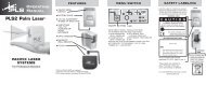
Laser Overview1. Rotating laser beam(head enclosed in glass lighthouse)2. Non-rotating laser beamfor plumb, squaring, orpipelineSafety LabelAvoid exposure.Laser light is emittedfrom this aperture.Caution/Certification Label(see previous page)7. Laser keypad6. Adjustable feetfor vertical setup3. Charger jack5. On/Off4. Bubble vial forvertical setupKeypad Overview5. Decrease rotation speed /scanning angle4. Increase rotation speed /scanning angle3. Scanning on / off6. Slope match / Move scanplane or plumb point to left7. Slope match / Move scanplane or plumb point to right1. H.I. Alert 2. Auto / Manual mode9. LED H.I. Alert /Y & Z axes calibration8. LED for manualmode / X axiscalibration3
How To Use The <strong>LT300</strong>SetupHorizontalThe laser can be used on a 5/8-11 tripod, on a wall mount, or directly on asolid, stable surface.VerticalThe laser can be placed directly on a solid, stable surface.Place the laser on the side with the two adjustable feet (6). Rough level thelaser by using the feet to center the bubble in the vertical vial (4).The <strong>LT300</strong> has a wide self-leveling range; however, if the laser is set up outof the leveling range, laser beam will continue to blink and rotation will notstart.Turning On the LaserTurn on the laser with the On / Off key (5). It does a self-test and the beamblinks while the laser is self-leveling. After it’s leveled, the head rotates.Automatic/Manual ModeThe laser is in automatic self-leveling mode when turned on.To put in manual mode, press (2) on the laser keypad. The LED indicator (8)located near the Auto/Man key will blink to remind you that the laser is inmanual mode.You cannot use H.I. Alert in Manual Mode.CAUTION: In manual mode, the beam rotates even if the laser is not leveled.4
H.I. AlertH.I. (height of instrument) Alert stops the laser automatically if the laser isdisturbed or moved, preventing inaccurate readings.It will function only when selected. To activate this safeguard feature, pressthe H.I. key (1). The LED indicator (9) will blink rapidly while the laser isself-leveling.About 30 seconds after the head starts to rotate, the LED will blink slowly,indicating the H.I. alert is activated.If the laser is disturbed while in H.I. Alert mode, the head will stop rotating, thebeam will turn off, and the LED will stay on.To start the laser rotating again, press On/Off twice.Check if the beam elevation has changed from its original benchmarkposition.The laser is no longer in H.I. Alert mode. Press key (1) to return to H.I.Alert.RotationRotation SpeedThe head rotates at 6 speeds: 0, 90, 150, 300, 450, and 600 rpm. 300 rpm isthe default setting.Using the keypad or remote, you can stop the rotation with the - key andmove the beam point with the + or - keys.To start the rotation again just press the + key for a few seconds.Press the + to increase the rotation or - to decrease the rotation speed.The laser beam is more visible at slower rotation speeds. The faster speed(600 rpm) is required for many machine control receiver applications.It is important to check while you're using the laser that it has notbeen moved and that your setting is still accurate.5
ScanningScanning mode allows you to see the beam easier at a distance.To switch from rotation to scan, press the scanning key (3).Use the + or - keys on the keypad to change scan lengths.Hold down the < or > arrows to move the scan left or right.To stop scanning, press again on the scanning key (3).Slope MatchThe laser can be used to match manual slope on bothX and Y axes. Two modes are available:• Complete manual mode: X and Y axis will be both manual• Semi-automatic mode: X in automatic / Y in manual.Semi-Automatic ModeSet the laser over a start point. Turn the laser so that the back of the laser, +Y,faces the direction of the slope (and -Y faces away). Use the sighting grooveon the top of the housing to roughly align the Y axis of the laser to thesecond point.After turning the laser on and allowing it to self-level, hold the Auto/Mankey for a few seconds until the LED below it (8) is lit continually. The laser isin automatic self-leveling mode in X axis, and manual mode in Y axis. Press< on the keypad or remote to match a positive slope in Y and > to match anegative slope. The X axis will stay level.Press twice on the Auto/Man key to return to the automatic mode.Manual ModeSet the laser over a start point. Turn the laser so that +X faces the directionof the slope (and -X faces away). Use the sighting groove on the top of thehousing to roughly align the X axis of the laser to the second point.After turning the laser on and allowing it to self-level, press the Auto/Mankey. The LED below it (8) will blink, indicating you’re in manual mode andcan match slope in the X axis. The head will start rotating.Press < on the keypad or remote to match a positive slope in X and > (9) tomatch a negative slope.6
To switch to the Y axis, press the H.I. key. Both LEDs (8 and 9) will blink,indicating you’re in manual mode and can match slope in the Y axis.Note: The Y axis grade will be at a 90 degree angle from the X axis gradeoutput. Press < to match a positive slope in Y and > to match a negativeslope.Press the Auto/Man key to return to automatic mode.Caution: In manual mode, the beam rotates even if the laser is not leveled. TheH.I. Alert function is not available when the unit is in manual mode.Adjusting Beam Left or RightAfter placing the laser in vertical position (see Setup section), the plumbbeam out the top of the head can be moved to the left or right, using the keys. This is necessary to do squaring for installing walls and partitions.BatteriesLaser BatteryThe <strong>LT300</strong> has a NiCad rechargeable battery that should be charged for 15hours before first use.Charging the Battery1) Remove the charging connector cover on the side of the laser. Insert thecharger plug and fully engage the threads.2) Plug the charger into an electrical outlet (110 volts or 220 volts,depending on charger and country).3) Charge for 15 hours. When the charger is plugged in, a red light willilluminate on the charger.The <strong>LT300</strong> can be charged while working. If electricity is available on the jobsite, simply plug in the charger and keep on working.For optimum life of the battery, it is recommended to charge the batteryafter fully discharged. To assure battery life, do not charge over 20 hours.Although the <strong>LT300</strong> is waterproof,do not charge it while it is in water or submerged.7
Checking and Adjusting the <strong>LT300</strong>THIS CHAPTER IS VERY IMPORTANT: Here are a few simpleinstructions to check your laser for calibration. Remember thatthe laser is a precision instrument and it is important that youkeep it calibrated and in proper condition. The accuracy of yourwork is completely your responsibility and you should regularlycheck your instrument, especially prior to important jobs.How to Check and CalibrateThe laser has 3 axes: X and Y (horizontal) and Z (vertical).Each axis must be checked for calibration. If needed, the axis can becalibrated, carefully following the instructions. You may also take the laserto a service center for calibration.Check and calibrate in this order:Check both sides of X axis.• If X is within spec, proceed to check both sides of Y.• If X needs calibration, calibrate X.Check both sides of Y axis.• If Y is within spec, proceed to final X to Y check• If Y needs calibration, calibrate Y; proceed to X to Y checkFinal X to Y check: compare +X, -Y, -X, +YCheck Z and calibrate if necessary8
Checking & Calibrating X & Y Axes1) Place the laser on a flat surface or tripod 100 ft. (30 m) away from awall. If too bright to see the beam, use a detector with a pole or graderod. Position so that -X is facing the wall (this is the side of the laserwith the On/Off key). Use the sighting groove on top of the instrumentfor alignment.2) Hold AUTO/MAN key. While holding, momentarily press the ON key.10Look for:Y/Z LED flashes, then X LED flashes. Release Auto/Man key.X LED will blink rapidly, indicating leveling. When the LED blinksslowly, the laser is ready to verify X axis calibration.3) To rotate laser beam: Press SCAN key on the remote (or press therotation key on the laser keypad).4) Check X calibration:a) With detector, mark center of the beam (-X).b) Rotate laser 180° so +X is facing wall or pole.c) With detector, mark center of the beam (+X).d) At 100 ft., the two marks should be no more than 1/4" apart.(At 30 m, no more than 6 mm apart.) If the marks are close enough,X axis is within calibration; proceed to Step 6.5) If not, the laser must be calibrated to bring the beam to the center ofthe two X marks. Use the ∧ or ∨ keys on the remote (< or > on thelaser keypad) to move beam up or down to the calibration target.Note: With the arrow keys, make small inputs: one click, two clicks, three clicks,etc. Do NOT hold key down.6) After calibrating X, check Y. Rotate laser 90° degrees so that -Y is facingthe wall (this is the side of the laser with the keypad).7) Select the Y axis by pressing the double arrow key (>>l) on the remote(or the HI key on the laser keypad).Look for:Y/Z LED blinking rapidly, indicating leveling. When the LED blinksslowly, the laser is ready to verify Y axis calibration.
8) Check Y calibration:a) With detector, mark center of the beam (-Y).b) Rotate laser 180° so +Y is facing wall.c) With detector, mark the center of the beam (+Y).d) At 100 ft., the two marks should be no more than 1/4" apart.(At 30 m, no more than 6 mm apart.) If the marks are close enough,Y axis is within calibration; proceed to Step 10.9) If not, the laser must be calibrated to bring the beam to the center ofthe two Y marks. Use the ∧ or ∨ keys on the remote (< or > on the laserkeypad) to move beam up or down to the calibration target.10) Final X to Y check: compare X to Y axes to be sure that your adjustedcalibration is within specification of ± 1/8" at 100 ft. (± 3 mm at 30 m).Turn the laser 90° each time; the marks for +X, -Y, -X, +Y should not bemore than 1/4" (6 mm) apart.11) Press the key on the remote with the small dot to save the calibration(or press the Auto/Man key on the laser)If you are not sure of the calibration and do not wish to save it, do not press thesmall dot, and turn the laser off with the On/Off key.Checking Z Axis1) Place the laser in vertical mode on a solid, stable surface about 20 ft.(6 m) away from a plumb line (plumb bob or heavy object hanging ona string, at least 8 ft. (2.5 m) high. You will be comparing the rotatingbeam to the plumb line. If you need to calibrate, the beam will be easierto see in a darkened room.2) Rough level the laser using the adjustable feet to center the bubble inthe vertical vial.3) Level the laser longitudinally with a bullet level.4) Turn on the laser.5) Use either scan or rotation mode. Using the scanning beam is easier,but if you cannot see the beam, work in rotation mode with a detector.6) Move the scan to the wall over the plumb line, sliding the laser left orright to line up the beam over the plumb line. If in rotation mode, usethe < or > arrows to move the beam.11
7) Move the scan up and down the entire length of the plumb line. If thebeam is slanted, and not vertical like the plumb line, the Z axis needs tobe calibrated.Calibrating Z AxisThe laser must be calibrated to bring the rotating Z beam parallel to theplumb line.1) Turn off the laser. Press and hold the Auto/Man key on the laser.2) Hold AUTO/MAN key. While holding, momentarily press the ON key.Look for:Y/Z LED flashes, then X LED flashes. Release Auto/Man key.Y/Z LED will blink rapidly, indicating leveling. When the LED blinksslowly, the laser is ready for Z axis calibration.3) Use the arrow keys to align scanning beam with string plumb line.4) Move the beam slightly so that the beam is over the plumb line for thefinal check.5) Press the small dot key on the remote to save calibration. The beamwill go off.12
Cone Error Checking1) Set up the laser about 2 ft. (60 cm) away from a wall (a) or pole and100 ft. (30 m) from another wall (b) or pole.2) Turn the laser on. After it has self-leveled, mark the location of thebeam on the near wall (a). Always mark the center of the beam. If it’stoo bright to see the beam, use a detector.3) Rotate the laser 180°. Mark the location of the beam on the far wall (b).4) Now set up the laser about 2 ft. (60 cm) away from the far wall.Mark the beam (b’) near the first mark (b).5) Rotate the laser 180°. Mark the location of the beam on the other wall(a’), near the first mark (a).6) Compare the two sets of marks on the walls. If the difference betweenaa’-bb’ exceeds 1/4" (6 mm), contact your local service center.13
Care and HandlingCAUTIONUse of control or calibration procedures other than those specified here inmay result in hazardous radiation exposure.1) The <strong>LT300</strong> is a precision instrument that must be handled withcare. Avoid shock and vibrations.2) After use, it’s recommend that you wipe the laser dry and store in a dryplace. Do not store the laser in its case if the laser or the case are wet.3) Do not store the laser at temperatures below -4°F (-20°C) or above176°F (80°C); the electronic components could be damaged.4) To maintain the precision of your laser, check and adjust it regularly.5) Keep the glass lighthouse of the laser clean with a soft cloth and glasscleaner.WarrantyYour <strong>LT300</strong> laser is guaranteed to be free of manufacturing defects for a periodof one year. Any abnormal usage, or if the instrument has been subjected toshock, will void this warranty. Under no circumstances will the liability ofthe manufacturer exceed the cost of repairing or replacing the instrument.Disassembling the laser by other than qualified technicians will void thewarranty. Specifications are subject to change without notice.14
Using the Detector1) Press the On/Off key to turn on the detector.2) Press the middle key to select the accuracy (deadband).3) Press the top key to select the sound level.4) Turn the detection window towards the laser beam, and move thedetector up or down according to the information given on the LCDdisplay. There are five channels of information, or grade indicators.A down arrow indicates you must move the detector down to reach thelaser reference; an up arrow, move it up.When a horizontal line appears on the display, the detector is at thesame level as the laser beam.5) Press the On/Off key to turn the detector off. It will automatically shutoff after ten minutes if not used (and give a warning beep).6) Keep the detection window clean, using a soft cloth and glass cleaner.17
Specifications:Range*Accuracy*Battery lifeEnvironmentalSize500 ft. (150 m) in detection mode;100 ft. (30 m) in remote modeFine: ± < 1/16” (1 mm)Standard: ± 1/8” (2.5mm)50 hrs; 9V alkalineWaterproof (IP66+)6” x 3.25” x 1.5”; .35 lbs.(15 x 8 x 3.5 cm; .2 kg)* Varies with laser used. Actual accuracy depends on beam diameter and distance to the laser.18
WARRANTYThe manufacturer warrants its measuring instruments againstall manufacturing defects for a period of one year from date ofpurchase. If during the warranty period, the product is consideredas defective by the manufacturer, the latter will decide whetherto repair or exchange the product. The only obligation and solerecourse of the buyer will be limited to this repair or exchange.The manufacturer, the distributor, or the retailer will in no case beresponsible for any incident or consequence, damage, etc. relativeto the use of those instruments.LIMITS AND EXCLUSIONS: The warranty will not apply to anydamage resulting from negligence, accident, misuse, repair, orstorage, or in case of abnormal use.19
2202 Redmond Rd., Jacksonville, AR 72076Toll Free: 800.643.9696Phone: 501.982.4433 . Fax: 501.982.0880sales@agl-lasers.comwww.agatec.comAM1032 Printed in USA 7/200720