natops flight manual navy model f/a-18a/b/c/d 161353 and up aircraft
natops flight manual navy model f/a-18a/b/c/d 161353 and up aircraft
natops flight manual navy model f/a-18a/b/c/d 161353 and up aircraft

You also want an ePaper? Increase the reach of your titles
YUMPU automatically turns print PDFs into web optimized ePapers that Google loves.
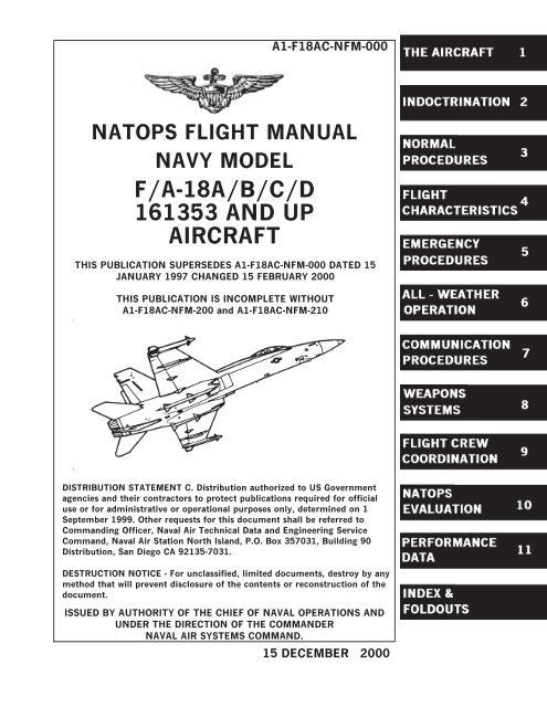
A1-F18AC-NFM-000NATOPS FLIGHT MANUALNAVY MODELF/A-18A/B/C/D<strong>161353</strong> AND UPAIRCRAFTTHIS PUBLICATION SUPERSEDES A1-F18AC-NFM-000 DATED 15JANUARY 1997 CHANGED 15 FEBRUARY 2000THIS PUBLICATION IS INCOMPLETE WITHOUTA1-F18AC-NFM-200 <strong>and</strong> A1-F18AC-NFM-210DISTRIBUTION STATEMENT C. Distribution authorized to US Governmentagencies <strong>and</strong> their contractors to protect publications required for officialuse or for administrative or operational purposes only, determined on 1September 1999. Other requests for this document shall be referred toComm<strong>and</strong>ing Officer, Naval Air Technical Data <strong>and</strong> Engineering ServiceComm<strong>and</strong>, Naval Air Station North Isl<strong>and</strong>, P.O. Box 357031, Building 90Distribution, San Diego CA 92135-7031.DESTRUCTION NOTICE - For unclassified, limited documents, destroy by anymethod that will prevent disclosure of the contents or reconstruction of thedocument.ISSUED BY AUTHORITY OF THE CHIEF OF NAVAL OPERATIONS ANDUNDER THE DIRECTION OF THE COMMANDERNAVAL AIR SYSTEMS COMMAND.15 DECEMBER 2000
A1-F18AC-NFM-000NATOPS FLIGHT MANUALNAVY MODELF/A-18A/B/C/D<strong>161353</strong> AND UPAIRCRAFTMcDonnell Douglas CorporationTHIS PUBLICATION SUPERSEDES A1-F18AC-NFM-000 DATED 15 JANUARY1997 CHANGED 15 FEBRUARY 2000THIS PUBLICATION IS INCOMPLETE WITHOUT A1-F18AC-NFM-200AND A1-F18AC-NFM-210DISTRIBUTION STATEMENT C. Distribution authorized to US Governmentagencies <strong>and</strong> their contractors to protect publications required for officialuse or for administrative or operational purposes only, determined on 1September 1999. Other requests for this document shall be referred toComm<strong>and</strong>ing Officer, Naval Air Technical Data <strong>and</strong> Engineering ServiceComm<strong>and</strong>, Naval Air Station North Isl<strong>and</strong>, P.O. Box 357031, Building 90Distribution, San Diego CA 92135-7031.DESTRUCTION NOTICE - For unclassified, limited documents, destroy by anymethod that will prevent disclosure of the contents or reconstruction of thedocument.ISSUED BY AUTHORITY OF THE CHIEF OF NAVAL OPERATIONS ANDUNDER THE DIRECTION OF THE COMMANDERNAVAL AIR SYSTEMS COMMAND.0801LP10080501 (Reverse Blank) 15 DECEMBER 2000CHANGE 1—15JULY 2001NATEC ELECTRONIC MANUAL
A1-F18AC-NFM-00015 December, 2000LETTER OF PROMULGATION1. The Naval Air Training <strong>and</strong> Operating Procedures St<strong>and</strong>ardization (NATOPS) Program is a positiveapproach toward improving combat readiness <strong>and</strong> achieving a substantial reduction in the <strong>aircraft</strong> mishaprate. St<strong>and</strong>ardization, based on professional knowledge <strong>and</strong> experience, provides the basis for developmentof an efficient <strong>and</strong> sound operational procedure. The st<strong>and</strong>ardization program is not planned to stifleindividual initiative, but rather to aid the comm<strong>and</strong>ing officer in increasing the unit's combat potentialwithout reducing comm<strong>and</strong> prestige or responsibility.2. This <strong>manual</strong> st<strong>and</strong>ardizes ground <strong>and</strong> <strong>flight</strong> procedures but does not include tactical doctrine.Compliance with the stipulated <strong>manual</strong> requirements <strong>and</strong> procedures is m<strong>and</strong>atory except as authorizedherein. In order to remain effective, NATOPS must be dynamic <strong>and</strong> stimulate rather than s<strong>up</strong>pressindividual thinking. Since aviation is a continuing, progressive profession, it is both desirable <strong>and</strong> necessarythat new ideas <strong>and</strong> new techniques be expeditiously evaluated <strong>and</strong> incorporated if proven to be sound. Tothis end, comm<strong>and</strong>ing officers of aviation units are authorized to modify procedures contained herein, inaccordance with the waiver provisions established by OPNAVINST 3710.7, for the purpose of assessingnew ideas prior to initiating recommendations for permanent changes. This <strong>manual</strong> is prepared <strong>and</strong> keptcurrent by the users in order to achieve maximum readiness <strong>and</strong> safety in the most efficient <strong>and</strong> economicalmanner. Should conflict exist between the training <strong>and</strong> operating procedures found in this <strong>manual</strong> <strong>and</strong> thosefound in other publications, this <strong>manual</strong> will govern.3. Checklists <strong>and</strong> other pertinent extracts from this publication necessary to normal operations <strong>and</strong>training should be made <strong>and</strong> carried for use in naval <strong>aircraft</strong>.M. J. McCABERear Admiral, U.S. NavyDirector, Air Warfare3 (Reverse Blank)ORIGINAL
A1-F18AC-NFM-000NATOPS Flight ManualCONTENTSPageNo.PART ICHAPTER 1THE AIRCRAFTThe Aircraft1.1 AIRCRAFT DESCRIPTION ........................................ I-1-11.1.1 Meet The Hornet. ................................................... I-1-11.1.2 Aircraft Dimensions.................................................. I-1-11.1.3 Aircraft Gross Weight................................................ I-1-11.1.4 Mission. ............................................................ I-1-21.2 BLOCK NUMBERS ................................................ I-1-2CHAPTER 2Systems2.1 POWER PLANT SYSTEMS ........................................ I-2-12.1.1 Engines. ............................................................. I-2-12.1.2 Automatic Throttle Control (ATC)................................... I-2-82.2 FUEL SYSTEM .................................................... I-2-102.2.1 Survivability. ........................................................ I-2-102.2.2 Fuel Tank Pressurization <strong>and</strong> Vent. ................................. I-2-102.2.3 Internal Transfer ................................................... I-2-112.2.4 External Transfer.................................................... I-2-132.2.5 Fuel Feed System.................................................... I-2-132.2.6 Fuel Recirculation System. .......................................... I-2-162.2.7 Fuel Dump System. ................................................. I-2-172.2.8 Fuel Lo Level Indications. ........................................... I-2-172.2.9 Fuel Quantity Indicating System (F/A-18A/B). ...................... I-2-182.2.10 Fuel Quantity Indicating System (F/A-18C/D). ...................... I-2-192.2.11 Air Refueling System. ............................................... I-2-222.2.12 Ground Refueling System. ........................................... I-2-222.3 FLIGHT PERFORMANCE ADVISORY SYSTEM ................. I-2-242.3.1 Flight Performance Advisory System (FPAS) (F/A-18A AircraftAFTER AFC 253 OR 292, <strong>and</strong> F/A-18C/D Aircraft.)................. I-2-242.4 SECONDARY POWER SYSTEM .................................. I-2-262.4.1 Airframe Mounted Accessory Drive (AMAD)......................... I-2-272.4.2 Auxiliary Power Unit (APU). ........................................ I-2-282.4.3 External Power Start. ............................................... I-2-292.4.4 Bleed Air Augmentation. ............................................ I-2-292.5 ELECTRICAL POWER SUPPLY SYSTEM ....................... I-2-305ORIGINAL
A1-F18AC-NFM-000PageNo.2.5.1 AC Electrical Power. ................................................ I-2-302.5.2 DC Electrical Power (Aircraft <strong>161353</strong> THRU 161528 BEFORE AFC049). ................................................................ I-2-312.5.3 DC Electrical Power (AIRCRAFT 161702 AND UP ANDAIRCRAFT <strong>161353</strong> THRU 161528 AFTER AFC049). ............... I-2-352.5.4 External Electrical Power. ........................................... I-2-362.5.5 Circuit Breakers. .................................................... I-2-372.6 LIGHTING ........................................................ I-2-372.6.1 Exterior Lighting. ................................................... I-2-372.6.2 Interior Lighting. .................................................... I-2-392.7 HYDRAULIC POWER SUPPLY SYSTEM ........................ I-2-412.7.1 Pumps <strong>and</strong> Reservoirs. .............................................. I-2-412.7.2 Hydraulic Circuits. .................................................. I-2-422.7.3 Valves. .............................................................. I-2-422.7.4 Accumulators. ....................................................... I-2-432.8 FLIGHT CONTROL SYSTEM ..................................... I-2-432.8.1 Application. ......................................................... I-2-432.8.2 Primary Flight Controls.............................................. I-2-432.8.3 Secondary Flight Controls. .......................................... I-2-542.8.4 Flaps. ............................................................... I-2-542.9 AUTOMATIC FLIGHT CONTROL SYSTEM (AFCS) ............. I-2-592.9.1 AFCS Caution <strong>and</strong> Advisory Displays. ............................... I-2-592.9.2 Pilot Relief Modes .................................................. I-2-602.10 LANDING SYSTEM ............................................... I-2-622.10.1 L<strong>and</strong>ing Gear System. ............................................... I-2-622.10.2 Nosewheel Steering System. ......................................... I-2-652.10.3 Brake System ....................................................... I-2-652.10.4 Launch Bar System. ................................................. I-2-672.10.5 Arresting Hook System. ............................................. I-2-672.11 WING FOLD SYSTEM ............................................ I-2-682.11.1 Wing Fold H<strong>and</strong>le. .................................................. I-2-682.12 INSTRUMENTS ................................................... I-2-692.12.1 Pitot-Static System. ................................................. I-2-692.12.2 St<strong>and</strong>by Attitude Reference Indicator................................ I-2-702.12.3 St<strong>and</strong>by Airspeed Indicator. ......................................... I-2-702.12.4 St<strong>and</strong>by Altimeter. .................................................. I-2-702.12.5 RADAR Altimeter Set (AN/APN-194(V)). ........................... I-2-702.12.6 St<strong>and</strong>by Rate of Climb Indicator..................................... I-2-722.12.7 Clock. ............................................................... I-2-726ORIGINAL
A1-F18AC-NFM-000PageNo.2.12.8 Integrated Fuel/Engine Indicator (IFEI) Time Displays (F/A-18C/D)................................................................. I-2-722.12.9 St<strong>and</strong>by Magnetic Compass.......................................... I-2-742.12.10 Angle-Of-Attack (AOA) Indexer...................................... I-2-742.13 AVIONICS SUBSYSTEM .......................................... I-2-752.13.1 Mission Computer (MC) System. .................................... I-2-752.13.2 Master Modes. ...................................................... I-2-842.13.3 Cockpit Controls <strong>and</strong> Displays. ...................................... I-2-852.13.4 Multipurpose Display Gro<strong>up</strong>. ........................................ I-2-852.13.5 Upfront Control (UFC). ............................................. I-2-1052.13.6 Signal Data Computer (F/A-18C/D).................................. I-2-1072.13.7 Video Tape Recording System(VTRS)(Aircraft <strong>161353</strong> THRU164912 before AFC 207).............................................. I-2-1072.13.8 Cockpit Video Recording System (Aircraft 164945 AND UP <strong>and</strong>Aircraft 163985 THRU 164912 after AFC 207). ...................... I-2-1082.13.9 Armpit Camera System. ............................................. I-2-1102.13.10 ALE-39 Countermeasures Dispensing Set(CMDS). .................. I-2-1102.13.11 ALE-47 Countermeasures Dispensing Set. ........................... I-2-1102.14 FIRE DETECTION/EXTINGUISHING SYSTEMS ................ I-2-1102.14.1 Fire Warning /Extinguisher Lights/Voice Alert....................... I-2-1102.14.2 Fire Extinguisher Pushbutton........................................ I-2-1102.14.3 APU Fire Extinguishing System. .................................... I-2-1112.14.4 Engine/AMAD Fire Extinguishing System. .......................... I-2-1112.14.5 Fire <strong>and</strong> Bleed Air Test Switch. ..................................... I-2-1112.15 ENTRANCE/EGRESS SYSTEMS ................................. I-2-1122.15.1 Canopy System. ..................................................... I-2-1122.15.2 Boarding Ladder..................................................... I-2-1162.15.3 Ejection Seat. ....................................................... I-2-1172.16 ENVIRONMENTAL CONTROL SYSTEM ........................ I-2-1262.16.1 Bleed Air System. ................................................... I-2-1262.16.2 Cockpit Air Conditioning <strong>and</strong> Pressurization. ........................ I-2-1282.16.3 Defogging System.................................................... I-2-1292.16.4 Windshield Anti-Ice <strong>and</strong> Rain Removal System. ..................... I-2-1292.16.5 Suit Ventilation System.............................................. I-2-1292.16.6 Anti-G System....................................................... I-2-1302.16.7 Avionics Cooling <strong>and</strong> Pressurization.................................. I-2-1302.17 EMERGENCY EQUIPMENT ...................................... I-2-1302.17.1 Jettison Systems. .................................................... I-2-1302.17.2 Warning/Caution/Advisory Lights <strong>and</strong> Displays. ..................... I-2-1312.17.3 Voice Alert System. ................................................. I-2-1327ORIGINAL
A1-F18AC-NFM-000PageNo.2.18 OXYGEN SYSTEM ................................................ I-2-1382.18.1 Normal Oxygen S<strong>up</strong>ply (Aircraft <strong>161353</strong> THRU 164068). ............ I-2-1382.18.2 Emergency Oxygen S<strong>up</strong>ply (Aircraft <strong>161353</strong> THRU 164068).......... I-2-1382.18.3 On-Board Oxygen Generating System (OBOGS) (Aircraft 164196AND UP)............................................................ I-2-1382.19 AIR DATA COMPUTER (ADC) ................................... I-2-1412.19.1 Angle-Of-Attack Probes.............................................. I-2-1412.19.2 Total Temperature Probe. ........................................... I-2-1422.20 STATUS MONITORING SUBSYSTEM ........................... I-2-1422.20.1 Flight Incident Recorder <strong>and</strong> Aircraft Monitoring Set (FIRAMS)(F/A-18C/D)......................................................... I-2-1422.20.2 Deployable Flight Incident Recorder Set (DFIRS) (Aircraft 164627AND UP)............................................................ I-2-1452.20.3 Avionic BIT. ........................................................ I-2-1452.20.4 Non-Avionic BIT. ................................................... I-2-1622.20.5 Status Monitoring Back<strong>up</strong>. ......................................... I-2-1632.20.6 Non-BIT Status. .................................................... I-2-1632.21 FIGHTER/ATTACK/TRAINER/RECCE (F/A-18B/D) ............. I-2-1672.21.1 F/A-18B/D Aircraft 161354 THRU 163778. .......................... I-2-1672.21.2 F/A-18D Aircraft 163986 AND UP .................................. I-2-1672.21.3 Aircraft Dimensions.................................................. I-2-1672.21.4 Aircraft Gross Weight................................................ I-2-1672.21.5 Fuel Quantity........................................................ I-2-1672.21.6 Canopy System. ..................................................... I-2-1682.21.7 Ejection Seat System. ............................................... I-2-1682.21.8 Intercom Controls. .................................................. I-2-1702.21.9 Rear Cockpit. ....................................................... I-2-170CHAPTER 3Service <strong>and</strong> H<strong>and</strong>ling3.1 SERVICING ....................................................... I-3-1CHAPTER 4Operating Limitations4.1 AIRCRAFT ........................................................ I-4-14.1.1 Engine Limitations ................................................. I-4-14.1.2 Airspeed Limitations. ............................................... I-4-24.1.3 Prohibited Maneuvers .............................................. I-4-34.1.4 CG Limitations ..................................................... I-4-54.1.5 Lateral Weight Asymmetry Limitations ............................. I-4-64.1.6 Angle-of-Attack (AOA) Limitations ................................. I-4-64.1.7 Weight Limitations. ................................................. I-4-84.1.8 Acceleration Limitations ............................................ I-4-98ORIGINAL
A1-F18AC-NFM-000PageNo.4.2 EXTERNAL STORES .............................................. I-4-94.2.1 Limitations. ......................................................... I-4-94.2.2 Banner Towing Limitations. ......................................... I-4-94.2.3 Tow Banner Adapter Limitations. ................................... I-4-9PART IICHAPTER 5INDOCTRINATIONIndoctrination5.1 GROUND TRAINING SYLLABUS ................................ II-5-15.1.1 Minimum Ground Training Syllabus. ................................ II-5-15.2 FLIGHT TRAINING SYLLABUS TRAINING PHASES ........... II-5-15.3 PERSONAL FLYING EQUIPMENT ............................... II-5-15.3.1 Minimum Requirements. ............................................ II-5-15.4 QUALIFICATIONS AND CURRENCY REQUIREMENTS ........ II-5-15.4.1 Minimum Flight Qualifications....................................... II-5-15.4.2 Requirements For Various Flight Phases ............................ II-5-15.4.3 Ceiling/Visibility Requirements. ..................................... II-5-25.4.4 Ferry Squadrons. .................................................... II-5-25.5 WAIVERS .......................................................... II-5-25.5.1 Unit Comm<strong>and</strong>ers Authority. ........................................ II-5-2PART IIICHAPTER 6NORMAL PROCEDURESFlight Preparation6.1 MISSION PLANNING ............................................. III-6-16.1.1 General. ............................................................. III-6-16.1.2 Flight Codes. ........................................................ III-6-16.2 BRIEFING/DEBRIEFING ......................................... III-6-16.2.1 Briefing.............................................................. III-6-16.2.2 Debriefing. .......................................................... III-6-3CHAPTER 7Shore-Based Procedures7.1 PREFLIGHT CHECK .............................................. III-7-17.1.1 Line Operations...................................................... III-7-17.1.2 Exterior Inspection. ................................................. III-7-17.1.3 Before Entering Cockpit ............................................ III-7-67.1.4 Interior Check ...................................................... III-7-97.1.5 Engine Start. ........................................................ III-7-127.1.6 Before Taxi ......................................................... III-7-169ORIGINAL
A1-F18AC-NFM-000PageNo.7.1.7 Taxi. ................................................................ III-7-207.2 TAKEOFF ......................................................... III-7-207.2.1 Before Takeoff ..................................................... III-7-207.2.2 Normal Takeoff...................................................... III-7-217.2.3 Crosswind Takeoff. .................................................. III-7-227.2.4 Formation Takeoff................................................... III-7-227.2.5 After Takeoff........................................................ III-7-227.2.6 Climb................................................................ III-7-237.2.7 10,000 Feet .......................................................... III-7-237.2.8 Cruise. .............................................................. III-7-237.3 LANDING ......................................................... III-7-237.3.1 Descent/Penetration. ................................................ III-7-237.3.2 Approach. ........................................................... III-7-247.3.3 Touchdown. ......................................................... III-7-247.3.4 Nosewheel Steering. ................................................. III-7-257.3.5 L<strong>and</strong>ing Rollout. .................................................... III-7-267.3.6 Braking Technique. ................................................. III-7-267.3.7 Crosswind L<strong>and</strong>ing. ................................................. III-7-267.3.8 Wet Runway L<strong>and</strong>ing................................................ III-7-267.3.9 Asymmetric Stores L<strong>and</strong>ing.......................................... III-7-277.3.10 Waveoff. ............................................................ III-7-277.4 POSTFLIGHT ..................................................... III-7-277.4.1 After L<strong>and</strong>ing. ...................................................... III-7-277.4.2 Hot Refueling........................................................ III-7-297.4.3 Before Engine Shutdown ........................................... III-7-307.4.4 Engine Shutdown ................................................... III-7-317.5 REAR COCKPIT PROCEDURES (F/A-18B/D) ..................... III-7-327.5.1 Before Entering Cockpit ............................................ III-7-327.5.2 Interior Check ...................................................... III-7-327.5.3 Before Taxi ......................................................... III-7-347.5.4 Before Takeoff ..................................................... III-7-347.5.5 Descent/Penetration ................................................ III-7-347.5.6 Approach ........................................................... III-7-347.5.7 After L<strong>and</strong>ing ...................................................... III-7-347.5.8 Before Engine Shutdown ............................................ III-7-347.6 NIGHT FLYING ................................................... III-7-357.6.1 External Light Management. ........................................ III-7-35CHAPTER 8Carrier-Based Procedures8.1 GENERAL ......................................................... III-8-110ORIGINAL
A1-F18AC-NFM-000PageNo.8.1.1 Carrier Electromagnetic Environment. ............................... III-8-18.1.2 Carrier INS Environment. .......................................... III-8-28.2 DAY OPERATIONS ............................................... III-8-28.2.1 Pre<strong>flight</strong>. ............................................................ III-8-28.2.2 Engine Start. ........................................................ III-8-28.2.3 Taxi ................................................................ III-8-28.2.4 Hangar Deck Operation. ............................................. III-8-38.2.5 Before Catapult Hook-Up............................................ III-8-38.2.6 Catapult Hook-Up. .................................................. III-8-48.2.7 Catapult Afterburner Operation...................................... III-8-68.2.8 Catapult Launch .................................................... III-8-68.2.9 Catapult Suspend.................................................... III-8-88.2.10 L<strong>and</strong>ing Pattern. .................................................... III-8-88.2.11 ATC Approach Mode Technique. .................................... III-8-118.2.12 Glideslope. .......................................................... III-8-118.2.13 Waveoff. ............................................................ III-8-118.2.14 ACL Mode 1 <strong>and</strong> 1A Approaches. ................................... III-8-118.2.15 ACL Mode 2 Approach. ............................................. III-8-138.2.16 Arrested L<strong>and</strong>ing <strong>and</strong> Exit From the L<strong>and</strong>ing Area. ................. III-8-168.3 NIGHT OPERATIONS ............................................ III-8-168.3.1 General. ............................................................. III-8-168.3.2 Pre<strong>flight</strong>. ............................................................ III-8-168.3.3 Before Taxi. ......................................................... III-8-168.3.4 Taxi. ................................................................ III-8-168.3.5 Catapult Hook-Up. .................................................. III-8-168.3.6 Catapult Launch..................................................... III-8-168.3.7 Aircraft or Catapult Malfunction..................................... III-8-168.3.8 L<strong>and</strong>ing Pattern. .................................................... III-8-178.3.9 Arrestment <strong>and</strong> Exit From the L<strong>and</strong>ing Area. ....................... III-8-178.4 SECTION CCA ..................................................... III-8-17CHAPTER 9Special Procedures9.1 FORMATION FLIGHT ............................................ III-9-19.1.1 Formation Taxi/Takeoff. ............................................ III-9-19.1.2 Aborted Takeoff. .................................................... III-9-19.1.3 Parade............................................................... III-9-39.1.4 Cruise Formation. ................................................... III-9-39.1.5 Section Approaches/L<strong>and</strong>ing. ........................................ III-9-59.2 AIR REFUELING .................................................. III-9-69.2.1 Before Plug-in. ...................................................... III-9-69.2.2 Refueling Technique. ................................................ III-9-611ORIGINAL
A1-F18AC-NFM-000PageNo.9.3 BANNER TOWING SYSTEM ..................................... III-9-89.3.1 Banner Towed Target Equipment.................................... III-9-89.3.2 Ground Procedures. ................................................. III-9-89.3.3 Flight Procedures. ................................................... III-9-89.3.4 Target Chase Procedures ........................................... III-9-109.4 NIGHT VISION DEVICE (NVD) OPERATIONS .................. III-9-119.4.1 Effects on Vision. ................................................... III-9-119.4.2 Effects of Light. ..................................................... III-9-119.4.3 Weather Conditions.................................................. III-9-119.4.4 Object/Target Detection. ............................................ III-9-129.4.5 Flight Preparation. .................................................. III-9-129.5 SHORT AIRFIELD FOR TACTICAL SUPPORT (SATS)PROCEDURES .................................................... III-9-129.5.1 L<strong>and</strong>ing Pattern. .................................................... III-9-129.5.2 Approach. ........................................................... III-9-129.5.3 Waveoff. ............................................................ III-9-129.5.4 Arrested L<strong>and</strong>ing. ................................................... III-9-129.5.5 Bolter. .............................................................. III-9-129.5.6 Hot Seat Procedure ................................................. III-9-129.5.7 Alert Scramble Launch Procedures .................................. III-9-13CHAPTER 10Functional Check<strong>flight</strong> Procedures10.1 GENERAL ......................................................... III-10-110.1.1 Check<strong>flight</strong> Requirements F/A-18A/C (F/A-18B/D Front Cockpit) . . III-10-210.1.2 Check<strong>flight</strong> Requirements (Rear Cockpit). ........................... III-10-20PART IVCHAPTER 11FLIGHT CHARACTERISTICSFlight Characteristics11.1 HANDLING QUALITIES........................................... IV-11-111.1.1 Auto Flap Configuration. ............................................ IV-11-111.1.2 Pitch Stability. ...................................................... IV-11-111.1.3 Stick Force. ......................................................... IV-11-211.1.4 Over-the-Top Maneuvering. ......................................... IV-11-211.1.5 Pitch Co<strong>up</strong>ling....................................................... IV-11-211.1.6 Roll/Yaw Stability. .................................................. IV-11-311.1.7 Roll Co<strong>up</strong>ling. ....................................................... IV-11-311.1.8 Pitch-Up. ........................................................... IV-11-311.1.9 Asymmetric FLIR Pod H<strong>and</strong>ling Qualities (TFLIR, ATFLIR,NAVFLIR). ......................................................... IV-11-311.2 SPIN RECOVERY MODE (SRM) FLIGHT CHARACTERISTICS . IV-11-412ORIGINAL
A1-F18AC-NFM-000PageNo.11.3 FLYING QUALITIES AT HIGH LATERAL ASYMMETRIES(12,000 TO 26,000 FT-LBS) ......................................... IV-11-411.3.1 Crosswind L<strong>and</strong>ing. ................................................. IV-11-411.3.2 Touchdown. ......................................................... IV-11-511.4 HALF OR FULL FLAP, GEAR DOWN CONFIGURATION ....... IV-11-511.4.1 Directional Control. ................................................. IV-11-511.4.2 L<strong>and</strong>ing Characteristics. ............................................. IV-11-511.4.3 Flight Control Logic. ................................................ IV-11-511.4.4 Full Flap Stalls. ..................................................... IV-11-511.4.5 Half Flap Stalls...................................................... IV-11-611.4.6 Single Engine Minimum Control Airspeed (Vmc). ................... IV-11-611.4.7 Takeoff, L<strong>and</strong>ing, <strong>and</strong> Catapult Launch with High Lateral WeightAsymmetries. ....................................................... IV-11-611.4.8 Single Engine Waveoffs.............................................. IV-11-711.5 OUT-OF-CONTROL ............................................... IV-11-711.5.1 Prevention. .......................................................... IV-11-711.5.2 Departures........................................................... IV-11-711.5.3 Departure Recovery.................................................. IV-11-811.5.4 Asymmetric External Store Effects................................... IV-11-911.5.5 F/A-18B/D Departure Characteristics. ............................... IV-11-911.6 F/A-18A/B/C/D FALLING LEAF/SPIN MODES ................... IV-11-1111.6.1 Falling Leaf Mode. .................................................. IV-11-1111.6.2 Falling Leaf Behavior. ............................................... IV-11-1111.6.3 Falling Leaf Recovery................................................ IV-11-1211.6.4 Inverted Falling Leaf. ............................................... IV-11-1211.6.5 Falling Leaf <strong>and</strong> Transient Spin Arrows.............................. IV-11-1211.6.6 Recovery Cues for Falling Leaf....................................... IV-11-1211.6.7 Low Yaw Rate Spin Mode. .......................................... IV-11-1211.6.8 Descent Rate. ....................................................... IV-11-1211.6.9 Asymmetric Store/Thrust Effect on Low Yaw Rate Spin. ............ IV-11-1311.6.10 Intermediate Yaw Rate Spin. ........................................ IV-11-1311.6.11 Intermediate Yaw <strong>and</strong> Spin Oscillations.............................. IV-11-1311.6.12 Asymmetric Store Effects on Intermediate Yaw Rate Spin. ......... IV-11-1311.6.13 High Yaw Rate Spin. ................................................ IV-11-1311.6.14 Centerline Tank Effects on High Yaw Rate Spin. .................... IV-11-1411.6.15 Asymmetric Store Effects on High Yaw Rate Spin. .................. IV-11-1411.6.16 Inverted Spin Mode. ................................................ IV-11-1411.6.17 Spin Recovery Mode (SRM). ........................................ IV-11-1411.6.18 SRM Disengagement................................................. IV-11-1411.6.19 Spin Recovery. ...................................................... IV-11-1511.6.20 Manual SRM. ....................................................... IV-11-1511.6.21 Transient Comm<strong>and</strong> Arrows. ........................................ IV-11-1511.6.22 Comm<strong>and</strong> Arrow Delay. ............................................. IV-11-1513ORIGINAL
A1-F18AC-NFM-000PageNo.11.7 CENTER OF GRAVITY (CG) ...................................... IV-11-1711.7.1 CG Determination. .................................................. IV-11-17PART VCHAPTER 12EMERGENCY PROCEDURESGeneral Emergencies12.1 GENERAL.......................................................... V-12-112.1.1 Immediate Action Items. ............................................ V-12-112.1.2 Warning/Caution Advisory Displays.................................. V-12-1CHAPTER 13Ground Emergencies13.1 ENGINE FAILS TO START/HUNG START ...................... V-13-113.2 HOT START ....................................................... V-13-113.3 ENGINE FIRE ON GROUND ..................................... V-13-113.4 EGRESS ........................................................... V-13-213.5 EMERGENCY BRAKES ........................................... V-13-213.6 LOSS OF DIRECTIONAL CONTROL ON GROUND .............. V-13-313.7 PLANING LINK FAILURE ........................................ V-13-313.8 BLOWN TIRE ON TAKEOFF/LANDING ......................... V-13-413.9 BRAKE PROBLEM ................................................ V-13-4CHAPTER 14Takeoff Emergencies14.1 LAUNCH BAR MALFUNCTION ON TAKEOFF .................. V-14-114.2 EMERGENCY CATAPULT FLYAWAY ........................... V-14-114.3 ABORT ............................................................ V-14-214.4 EMERGENCY TAKEOFF .......................................... V-14-314.5 LOSS OF THRUST ON TAKEOFF ................................ V-14-314.6 LANDING GEAR FAILS TO RETRACT .......................... V-14-414.7 WOW System Failure ............................................... V-14-614ORIGINAL
A1-F18AC-NFM-000PageNo.CHAPTER 15In<strong>flight</strong> Emergencies15.1 ENGINE FIRE IN FLIGHT ........................................ V-15-115.2 AFTERBURNER FAILURE ....................................... V-15-115.3 RUNAWAY ENGINE/STUCK THROTTLE ....................... V-15-115.4 ENGINE FAILURE ................................................ V-15-215.5 ASYMMETRIC THRUST EFFECTS ............................... V-15-215.6 ENGINE STALL ................................................... V-15-315.7 RESTART ......................................................... V-15-415.8 INLET ICE CAUTION ............................................. V-15-715.9 POWER TRANSMISSION SHAFT (PTS) FAILURE............... V-15-815.10 HYDRAULIC FAILURE ........................................... V-15-815.11 HYD 1B FAILURE ................................................. V-15-915.12 HYD 1A AND 1B FAILURE ....................................... V-15-915.13 HYD 2A FAILURE ................................................. V-15-1015.14 HYD 2A AND 2B FAILURE ....................................... V-15-1115.15 FUSELAGE FUEL LEAK .......................................... V-15-1415.16 FUEL TRANSFER FAILURES .................................... V-15-1515.16.1 Aircraft <strong>161353</strong> THRU 161519 BEFORE AFC 039. ................. V-15-1515.16.2 Aircraft <strong>161353</strong> THRU 161519 AFTER AFC 039 AND 161520 ANDUP. ................................................................. V-15-1515.17 FEED TANK TRANSFER FAILURE .............................. V-15-1615.18 EXTERNAL TANK TRANSFER FAILURE ....................... V-15-1615.19 UNCOMMANDED FUEL DUMP .................................. V-15-1715.20 CSC MUX FAILURE .............................................. V-15-1815.21 DOUBLE GENERATOR OR DOUBLETRANSFORMER-RECTIFIER FAILURE ......................... V-15-1815ORIGINAL
A1-F18AC-NFM-000PageNo.15.21.1 Double Generator Failure. ........................................... V-15-1815.21.2 Transformer-Rectifier Failure. ...................................... V-15-1815.22 LOSS OF DC ESSENTIAL BUS ................................... V-15-2015.23 AMAD CAUTION .................................................. V-15-2515.24 AMAD PR CAUTION .............................................. V-15-2515.25 OXYGEN LEAK (Aircraft <strong>161353</strong> THRU 164068) .................. V-15-2515.26 OBOGS DEGRADE/FAILURE (Aircraft 164196 AND UP) .......... V-15-2515.27 COCKPIT TEMPERATURE HIGH ................................ V-15-2615.28 COCKPIT SMOKE, FUMES, OR FIRE ............................ V-15-2715.29 DISPLAY MALFUNCTION ........................................ V-15-2715.30 EXTERNAL STORES JETTISON ................................. V-15-2715.31 ADC FAILURE EFFECTS .......................................... V-15-2815.32 FCS FAILURE INDICATIONS AND EFFECTS ................... V-15-3015.32.1 Invalid FCS Status Display ......................................... V-15-3015.33 FCS FAILURE ..................................................... V-15-4115.34 FC AIR DAT CAUTION ........................................... V-15-4115.35 AOA PROBE DAMAGE ............................................ V-15-4115.35.1 AOA Indications With AOA Probe Damage. ........................ V-15-4115.35.2 Jammed AOA Probe On Takeoff. ................................... V-15-4215.36 PITOT STATIC PROBE DAMAGE. ............................... V-15-4315.37 DIRECT ELECTRICAL LINK (DEL) .............................. V-15-4315.37.1 Digital DEL - DEL ON Caution. .................................... V-15-4315.37.2 Digital DEL. ........................................................ V-15-4415.37.3 Analog DEL. ........................................................ V-15-4515.38 UNCOMMANDED YAW/ROLL - TAKEOFF/LANDINGCONFIGURATION ................................................ V-15-4615.39 UNCOMMANDED PITCH AND ROLL EXCURSIONS ........... V-15-4615.40 MECH ON CAUTION ............................................. V-15-4716ORIGINAL
A1-F18AC-NFM-000PageNo.15.41 MECH ON WITH AIL AND RUD OPERATIVE ................... V-15-4715.42 MECH ON WITH AIL AND RUD OFF............................. V-15-4815.43 FLAPS OFF CAUTION ............................................ V-15-4815.44 FLAP SCHED CAUTION .......................................... V-15-4915.45 NWS CAUTION ................................................... V-15-5015.46 AILERON FAILURE/AIL OFF CAUTION ......................... V-15-5015.47 RUDDER FAILURE/RUD OFF CAUTION ........................ V-15-5015.48 JAMMED CONTROLS ............................................ V-15-5115.49 OUT-OF-CONTROL ............................................... V-15-5115.49.1 Recovery Indications <strong>and</strong> Procedures ................................ V-15-5115.49.2 Departure/Falling Leaf .............................................. V-15-5215.49.3 Spin. ................................................................ V-15-5315.50 CONTROLLABILITY CHECK ..................................... V-15-54CHAPTER 16L<strong>and</strong>ing Emergencies16.1 SINGLE ENGINE FAILURE IN LANDING CONFIGURATION . . V-16-116.2 SINGLE ENGINE WAVEOFF/BOLTER ........................... V-16-216.3 SINGLE ENGINE LANDING ...................................... V-16-316.4 FORCED LANDING ............................................... V-16-616.5 PLANING LINK FAILURE ........................................ V-16-616.6 LANDING GEAR UNSAFE/FAILS TO EXTEND .................. V-16-716.7 LANDING GEAR EMERGENCY EXTENSION ................... V-16-916.8 LAUNCH BAR MALFUNCTION ON LANDING................... V-16-1116.9 HOOK FAILS TO EXTEND ....................................... V-16-1116.10 LANDING WITH BLOWN TIRE .................................. V-16-1116.11 LANDING WITH AFT CG ......................................... V-16-1416.12 AUTO FLAP LANDING ........................................... V-16-1417ORIGINAL
A1-F18AC-NFM-000PageNo.16.13 FIELD ARRESTMENT ............................................ V-16-1416.13.1 Field Arresting Gear. ................................................ V-16-1416.13.2 Short Field Arrestment. ............................................. V-16-1516.13.3 Long Field Arrestment............................................... V-16-1516.14 FIELD ARRESTMENT GEAR DATA ............................. V-16-1616.15 BARRICADE ARRESTMENT ..................................... V-16-16CHAPTER 17Ejection17.1 EJECTION ......................................................... V-17-117.1.1 General Injury Risks. ............................................... V-17-117.1.2 Injury Risks For Lighter Weight Crewmembers. ..................... V-17-217.1.3 Injury Risks For Heavier Weight Crewmembers. .................... V-17-217.1.4 Low Altitude Ejection. .............................................. V-17-317.1.5 High Altitude Ejection. ............................................. V-17-317.1.6 Ejection Procedures.................................................. V-17-417.2 DITCHING ........................................................ V-17-417.3 SEAWATER ENTRY .............................................. V-17-4CHAPTER 18Immediate Action18.1 GENERAL.......................................................... V-18-118.2 APU FIRE LIGHT ................................................. V-18-118.3 L BLEED <strong>and</strong> R BLEED WARNING LIGHTS (dual) .............. V-18-118.4 L BLEED or R BLEED WARNING LIGHT (single) ............... V-18-118.5 FIRE LIGHT ....................................................... V-18-218.6 L (R) ATS/OBOGS DEGRADE/FAILURE .......................... V-18-218.7 ENGINE CAUTIONS .............................................. V-18-318.8 ENGINE STALL ................................................... V-18-318.9 INLET ICE CAUTION ............................................. V-18-318.10 FLIGHT CONTROL CAUTIONS ................................... V-18-318.11 HOT START ....................................................... V-18-318ORIGINAL
A1-F18AC-NFM-000PageNo.18.12 EMERGENCY BRAKES ........................................... V-18-318.13 LOSS OF DIRECTIONAL CONTROL ON GROUND (Planing LinkFailure, Blown Tire on Takeoff/L<strong>and</strong>ing, Brake Problem) ........... V-18-318.14 EMERGENCY CATAPULT FLYAWAY ........................... V-18-418.15 ABORT ............................................................ V-18-418.16 EMERGENCY TAKEOFF ......................................... V-18-418.17 LOSS OF THRUST ON TAKEOFF ................................ V-18-518.18 FUSELAGE FUEL LEAK .......................................... V-18-518.19 DOUBLE GENERATOR OR DOUBLE TRANSFORMER -RECTIFIER FAILURE ............................................ V-18-518.20 COCKPIT SMOKE, FUMES, OR FIRE ............................ V-18-518.21 UNCOMMANDED YAW/ROLL - TAKEOFF/LANDINGCONFIGURATION ................................................ V-18-518.22 UNCOMMANDED PITCH AND ROLL EXCURSIONS ........... V-18-618.23 DEPARTURE/FALLING LEAF RECOVERY ...................... V-18-618.24 SPIN RECOVERY ................................................. V-18-618.25 SINGLE ENGINE FAILURE IN LANDING CONFIGURATION. . . V-18-7PART VICHAPTER 19ALL WEATHER PROCEDURESInstrument Flight19.1 INSTRUMENT FLIGHT .......................................... VI-19-119.1.1 Before Takeoff....................................................... VI-19-119.1.2 In<strong>flight</strong>. ............................................................. VI-19-119.1.3 Approaches ......................................................... VI-19-119.2 DEGRADED SYSTEMS ........................................... VI-19-1CHAPTER 20Extreme Weather Procedures20.1 ICE AND RAIN..................................................... VI-20-120.1.1 Ground Operation ................................................... VI-20-120.1.2 In<strong>flight</strong> ............................................................. VI-20-119ORIGINAL
A1-F18AC-NFM-000PageNo.20.2 TURBULENT AIR AND THUNDERSTORM OPERATION ...... VI-20-3CHAPTER 21Hot Weather Procedures21.1 BEFORE TAKEOFF ............................................... VI-21-121.2 INFLIGHT ......................................................... VI-21-121.3 DESCENT ......................................................... VI-21-121.4 AFTER LANDING ................................................. VI-21-1CHAPTER 22Cold Weather Procedures22.1 EXTERIOR INSPECTION ........................................ VI-22-122.2 BEFORE ENTERING COCKPIT .................................. VI-22-122.3 INTERIOR CHECK ................................................ VI-22-122.4 ENGINE START .................................................. VI-22-122.5 BEFORE TAXI .................................................... VI-22-122.5.1 Aircraft 164196 THRU 164912 BEFORE AFC 216. .................. VI-22-122.6 TAKEOFF ......................................................... VI-22-2PART VIICHAPTER 23COMM-NAV EQUIPMENT AND PROCEDURESCommunication-Identification Equipment23.1 INTERCOM SYSTEM ............................................. VII-23-123.1.1 Volume Control Before AFC 270 .................................... VII-23-123.1.1.2 Volume Control After AFC 270 ..................................... VII-23-123.2 VHF/UHF AND MIDS COMMUNICATION SYSTEM ............ VII-23-123.2.1 VHF/UHF/MIDS Controls <strong>and</strong> Indicators. ......................... VII-23-2A23.2.2 Normal <strong>and</strong> Plain Operation......................................... VII-23-523.3 SECURE SPEECH SYSTEM (KY-58) ............................. VII-23-623.3.1 KY-58 Control Panel Assembly. ..................................... VII-23-623.3.2 Controls <strong>and</strong> Indicators. ............................................ VII-23-723.3.3 KY-58 Operation. .................................................. VII-23-823.4 HAVE QUICK OPERATION AND OPTIONS (ARC-210)(AIRCRAFT 164865 AND UP, AND F/A-18A AFTER AFC 253 OR292.) ................................................................ VII-23-923.4.1 Preset Mode. ....................................................... VII-23-920CHANGE 1
A1-F18AC-NFM-000PageNo.23.4.2 Using HQ Time Options. ........................................... VII-23-1023.5 SINCGARS Operation <strong>and</strong> Options ................................. VII-23-1223.5.1 Preset Mode. ........................................................ VII-23-1223.5.2 Using Time Options in SG Display. ................................ VII-23-1223.5.3 Performing Electronic Remote Fill (ERF) with ERF Option. ....... VII-23-1323.6 IDENTIFICATION SYSTEM ...................................... VII-23-1423.6.1 Combined Interrogator Transponder (Aircraft 165222 AND UP <strong>and</strong>F/A-18A AFTER AFC 292.) ......................................... VII-23-1423.6.2 IFF Controls <strong>and</strong> Indicators. ....................................... VII-23-1623.6.3 IFF Emergency Operation. ......................................... VII-23-1823.6.4 COMMUNICATION-NAVIGATION-IDENTIFICATIONINTERFACE ....................................................... VII-23-19CHAPTER 24Navigation Equipment24.1 NAVIGATION CONTROLS AND INDICATORS................... VII-24-124.1.1 UFC. ............................................................... VII-24-124.1.2 Digital Map Set (DMS) (163985 AND UP)........................... VII-24-124.1.3 HSI Display. ........................................................ VII-24-224.1.4 DDI. ................................................................ VII-24-524.1.5 HUD. ............................................................... VII-24-524.1.6 Sensor Control Panel. ............................................... VII-24-524.1.7 Course Select Switch................................................. VII-24-824.1.8 Communication Control Panel. ...................................... VII-24-824.2 INERTIAL NAVIGATION SYSTEM (INS)/GLOBALPOSITIONING SYSTEM (GPS) ................................... VII-24-824.2.1 Inertial Navigation Unit (INU). ..................................... VII-24-924.2.2 INS BIT............................................................. VII-24-1124.2.3 INS Alignment Modes. .............................................. VII-24-1124.2.4 INS Check Display. ................................................. VII-24-2124.2.5 Waypoints, Offset Aimpoints (OAP) <strong>and</strong> Offsets. ................... VII-24-2124.2.6 Position Keeping. ................................................... VII-24-3524.2.7 Position Updating. .................................................. VII-24-3524.2.8 NAV/TAC Bank Limit Options (MC OFP 13C <strong>and</strong> 15C). ............ VII-24-3724.2.9 Steering. ............................................................ VII-24-3724.2.10 Designation. ......................................................... VII-24-4424.2.11 INS Updates (Not available in AINS) ............................... VII-24-4924.3 ADF (Automatic Direction Finder)................................... VII-24-5024.4 TACAN (Tactical Air Navigation). .................................. VII-24-5124.4.1 TACAN BIT......................................................... VII-24-5124.4.2 TACAN Mode Selection. ............................................ VII-24-5121CHANGE 1
A1-F18AC-NFM-000PageNo.24.4.3 TACAN Programming. .............................................. VII-24-5124.4.4 TACAN Position Keeping. .......................................... VII-24-5224.4.5 TACAN Position Updating. ......................................... VII-24-5224.5 ILS (INSTRUMENT LANDING SYSTEM) ........................ VII-24-5424.5.1 ILS Receiver......................................................... VII-24-5424.5.2 ILS Decoder. ........................................................ VII-24-5424.5.3 ILS BIT. ............................................................ VII-24-5424.5.4 ILS Initialization. ................................................... VII-24-5424.5.5 ILS Steering. ........................................................ VII-24-5724.6 DATA LINK SYSTEM ............................................. VII-24-5924.6.1 Automatic Carrier L<strong>and</strong>ing Mode. ................................... VII-24-59CHAPTER 25Back<strong>up</strong>/Degraded Operations25.1 MISSION COMPUTER NO. 1 FAILURE .......................... VII-25-125.1.1 Status Monitoring Functions......................................... VII-25-125.1.2 Navigation Functions. ............................................... VII-25-125.1.3 Back<strong>up</strong> HUD Display................................................ VII-25-125.1.4 Back<strong>up</strong> HSI Display. ................................................ VII-25-125.2 BACKUP ATTITUDE AND NAVIGATION SYSTEM ............. VII-25-225.2.1 St<strong>and</strong>by Attitude Reference Indicator................................ VII-25-225.2.2 Static Power Inverter. ............................................... VII-25-225.2.3 Magnetic Azimuth Detector.......................................... VII-25-225.2.4 Back<strong>up</strong> Attitude <strong>and</strong> Navigation System Controls <strong>and</strong> Indicators. . . . VII-25-225.3 NAVIGATION BACKUP ........................................... VII-25-325.3.1 Navigation Controls <strong>and</strong> Indicators ................................. VII-25-425.3.2 Back<strong>up</strong> Heading Mode Control. ..................................... VII-25-425.4 BACKUP FREQUENCY CONTROL ............................... VII-25-5CHAPTER 26CHAPTER 27PART VIIIPART IXCHAPTER 28Visual CommunicationsDeck/Ground H<strong>and</strong>ling SignalsWEAPONS SYSTEMSFLIGHT CREW COORDINATIONAircrew Coordination28.1 DEFINITION ...................................................... IX-28-128.2 CRITICAL SKILLS OF AIRCREW COORDINATION ............. IX-28-122ORIGINAL
A1-F18AC-NFM-000PageNo.28.2.1 Decision Making. .................................................... IX-28-128.2.2 Assertiveness. ....................................................... IX-28-128.2.3 Mission Analysis. .................................................... IX-28-128.2.4 Communication. ..................................................... IX-28-128.2.5 Leadership. ......................................................... IX-28-128.2.6 Adaptability/Flexibility. ............................................ IX-28-228.2.7 Situational Awareness................................................ IX-28-228.2.8 Factors That Degrade Aircrew Coordination ........................ IX-28-228.3 FLIGHT MEMBER POSITIONS .................................. IX-28-228.3.1 Mission Comm<strong>and</strong>er. ................................................ IX-28-228.3.2 Pilot In Comm<strong>and</strong>. .................................................. IX-28-328.3.3 Formation Leader.................................................... IX-28-328.3.4 Crew Member........................................................ IX-28-328.3.5 Weapons <strong>and</strong> Sensors Officer. ....................................... IX-28-328.4 AIRCREW RESPONSIBILITIES BY FLIGHT PHASE............. IX-28-328.4.1 Mission Planning <strong>and</strong> Briefing. ...................................... IX-28-328.4.2 Pretakeoff. .......................................................... IX-28-328.4.3 Takeoff/Departure. .................................................. IX-28-428.4.4 Enroute.............................................................. IX-28-428.4.5 Recovery............................................................. IX-28-428.4.6 Mission Critique. .................................................... IX-28-428.5 SPECIAL CONSIDERATIONS ..................................... IX-28-528.5.1 Functional Check<strong>flight</strong>s.............................................. IX-28-528.5.2 Formation Flights.................................................... IX-28-528.5.3 Air Combat Maneuvering (ACM). ................................... IX-28-528.6 EMERGENCIES ................................................... IX-28-5PART XCHAPTER 29NATOPS EVALUATIONNATOPS Evaluation29.1 CONCEPT ......................................................... X-29-129.1.1 Implementation...................................................... X-29-129.1.2 Definitions........................................................... X-29-129.2 GROUND EVALUATION .......................................... X-29-229.2.1 General. ............................................................. X-29-229.3 FLIGHT EVALUATION ........................................... X-29-329.3.1 Mission Planning/Briefing ........................................... X-29-329.3.2 Pre<strong>flight</strong>/Line Operations. ........................................... X-29-329.3.3 Taxi ................................................................ X-29-429.3.4 Takeoff (*) .......................................................... X-29-423ORIGINAL
A1-F18AC-NFM-000PageNo.29.3.5 Climb/Cruise ........................................................ X-29-429.3.6 Approach/L<strong>and</strong>ing (*) ............................................... X-29-429.3.7 Communications..................................................... X-29-429.3.8 Emergency/Malfunction Procedures (*). ............................. X-29-429.3.9 Post Flight Procedures .............................................. X-29-429.3.10 Mission Evaluation. ................................................. X-29-429.3.11 Applicable Publications. ............................................. X-29-429.3.12 Flight Evaluation Grading Criteria. .................................. X-29-529.3.13 Flight Evaluation Grade Determination. ............................. X-29-529.4 NATOPS EVALUATION QUESTION BANK ...................... X-29-6PART XIAPPENDIXPERFORMANCE DATAALPHABETICAL INDEXFOLDOUTS24ORIGINAL
A1-F18AC-NFM-000LIST OF ILLUSTRATIONSPageNo.CHAPTER 1Figure 1-1Figure 1-2CHAPTER 2Figure 2-1Figure 2-2Figure 2-3Figure 2-4Figure 2-5Figure 2-6Figure 2-7Figure 2-8Figure 2-9Figure 2-10Figure 2-11Figure 2-12Figure 2-13Figure 2-14Figure 2-15Figure 2-16Figure 2-17Figure 2-18Figure 2-19Figure 2-20Figure 2-21Figure 2-22Figure 2-23Figure 2-24Figure 2-25Figure 2-26Figure 2-27Figure 2-28Figure 2-29Figure 2-30Figure 2-31Figure 2-32Figure 2-33Figure 2-34Figure 2-35Figure 2-36The AircraftGeneral Arrangement (F/A-18A/C) .................................. I-1-2Block Numbers...................................................... I-1-3SystemsAfterburner Light-Off Time ......................................... I-2-2Throttle Grips....................................................... I-2-4Engine Monitor Display (EMD) ..................................... I-2-6Tank 1 <strong>and</strong> 4 Fuel CG Control <strong>and</strong> CG Caution Schedule ........... I-2-14Fuel Display......................................................... I-2-21Fuel Quantity (F/A-18A/C) .......................................... I-2-23FPAS Display ....................................................... I-2-25Secondary Power S<strong>up</strong>ply ............................................ I-2-27Electrical System.................................................... I-2-33Ground Power Panel <strong>and</strong> Placard ................................... I-2-38Hydraulic System ................................................... I-2-44Flight Control System Functional Diagram .......................... I-2-46Control Stick ........................................................ I-2-47SPIN Recovery Display.............................................. I-2-50Flap Schedules ...................................................... I-2-56FCS Status Display.................................................. I-2-58AFCS Controls <strong>and</strong> Indicators ....................................... I-2-61Emergency/Parking Brake H<strong>and</strong>le ................................... I-2-67Angle of Attack Indexer ............................................. I-2-75Mission Computer Functions <strong>and</strong> Multiplex System ................. I-2-77MUMI Display ...................................................... I-2-83Menu Display ....................................................... I-2-87Electronic Attitude Display Indicator................................ I-2-88HI/MPCD Controls <strong>and</strong> HSI Symbology............................. I-2-93HUD Controls....................................................... I-2-95HUD Symbology .................................................... I-2-100HUD Symbology Degrades .......................................... I-2-104Upfront Control (UFC) .............................................. I-2-105Canopy Birdstrike Resistance........................................ I-2-113Canopy Controls .................................................... I-2-115Boarding Ladder .................................................... I-2-116SJU-17 Ejection Modes.............................................. I-2-118Leg Restraint System................................................ I-2-121Survival Kit ......................................................... I-2-124Cockpit Pressurization Schedules .................................... I-2-128Visual Warning Cue ................................................. I-2-13725ORIGINAL
A1-F18AC-NFM-000PageNo.Figure 2-37Figure 2-38Figure 2-39Figure 2-40Figure 2-41Figure 2-42Figure 2-43Figure 2-44Figure 2-45Figure 2-46Figure 2-47Figure 2-48CHAPTER 4Figure 4-1Figure 4-2Figure 4-3Figure 4-4CHAPTER 7Figure 7-1Figure 7-2CHAPTER 8Figure 8-1Figure 8-2Figure 8-3Figure 8-4Figure 8-5CHAPTER 9Figure 9-1Figure 9-2CHAPTER 10Figure 10-1CHAPTER 11Figure 11-1Figure 11-2Figure 11-3OBOGS Monitor .................................................... I-2-141Status Monitoring Subsystem ....................................... I-2-143Flight Aids Reversion Mechanization ................................ I-2-146Caution/Advisory Indications ........................................ I-2-148BIT Control Display................................................. I-2-149ADC/INS/GPS BIT - AUTO BIT Display ........................... I-2-157DSPL/EPI (IFEI)/UFC BIT Displays ............................... I-2-158Configuration Display ............................................... I-2-164INS Post Flight Data Displays ...................................... I-2-166General Arrangement (F/A-18B/D) .................................. I-2-168Fuel Quantity (F/A-18B/D).......................................... I-2-169H<strong>and</strong> Controllers (F/A-18D Aircraft 163986 AND UP)............... I-2-174Operating LimitationsAirspeed Limitations ................................................ I-4-3System Limitations.................................................. I-4-3Acceleration Limitations............................................. I-4-10External Stores Limitations ......................................... I-4-12Shore-Based ProceduresChecklist Display.................................................... III-7-21Field L<strong>and</strong>ing Pattern Typical....................................... III-7-28Carrier-Based ProceduresLaunch Trim ........................................................ III-8-5Carrier L<strong>and</strong>ing Pattern ............................................. III-8-9Carrier Controlled Approach (CCA) ................................. III-8-10ACL Mode 1 <strong>and</strong> 1A Approaches .................................... III-8-14ACL Mode 2 Approach .............................................. III-8-15Special ProceduresFormation Takeoff Runway Alignments ............................. III-9-2Formations .......................................................... III-9-4Functional Check<strong>flight</strong> ProceduresEGT <strong>and</strong> N 1 Limits ................................................. III-10-11Flight CharacteristicsF/A-18B/D Departure Regions....................................... IV-11-10Reference CG ....................................................... IV-11-17CG Correction For Configuration/Stores/Ordnance .................. IV-11-1726ORIGINAL
A1-F18AC-NFM-000PageNo.Figure 11-4Figure 11-5Figure 11-6Figure 11-7Figure 11-8Figure 11-9Figure 11-10Figure 11-11Figure 11-12Figure 11-13Figure 11-14Figure 11-15Figure 11-16Figure 11-17Figure 11-18Figure 11-19CHAPTER 12Figure 12-1CHAPTER 14Figure 14-1CHAPTER 15Figure 15-1Figure 15-2Figure 15-3Figure 15-4Figure 15-5Figure 15-6Figure 15-7Figure 15-8Figure 15-9CHAPTER 16Figure 16-1CG Worksheet....................................................... IV-11-18Sample Problem, CG for a F/A-18C Model, Lot 14 Aircraft, GearDown................................................................ IV-11-19Sample Problem, CG for a F/A-18C Model, Lot 14 Aircraft, Gear Up IV-11-20CG Travel Due To Fuel Consumption - F/A-18A <strong>161353</strong> THRU163175 With CG Control System .................................... IV-11-21CG Travel Due To Fuel Consumption - F/A-18B 161354 THRU161360 Without CG Control System ................................. IV-11-22CG Travel Due To Fuel Consumption - F/A-18B 161704 THRU163123 With CG Control System .................................... IV-11-23CG Travel Due To Fuel Consumption - F/A-18C 163427 THRU164691 .............................................................. IV-11-24CG Travel Due To Fuel Consumption - F/A-18C 164693 AND UP . . . IV-11-25CG Travel Due To Fuel Consumption - F/A-18D 163434 THRU164692 .............................................................. IV-11-26CG Travel Due To Fuel Consumption - F/A-18D 164694 AND UP. . . IV-11-27CG vs Tanks 1&4Fuel - F/A-18A .................................. IV-11-28CG vs Tanks 1&4Fuel - F/A-18B .................................. IV-11-28CG vs Tanks 1&4Fuel - F/A-18C 163427 THRU 164691 ........... IV-11-28CG vs Tanks 1&4Fuel - F/A-18C 164693 AND UP................. IV-11-29CG vs Tanks 1&4Fuel - F/A-18D 163434 THRU 164692 ........... IV-11-29CG vs Tanks 1&4Fuel - F/A-18D 164694 AND UP ................ IV-11-29General EmergenciesWarning/Caution/Advisory Displays ................................. V-12-2Takeoff EmergenciesMaximum Weight for 100 FPM Single Engine Rate of Climb ........ V-14-5In<strong>flight</strong> EmergenciesSpooldown Restart Envelope ........................................ V-15-5Windmill Restart Envelope .......................................... V-15-5Crossbleed Restart Envelope ........................................ V-15-6APU Restart Envelope .............................................. V-15-6Hydraulic Flow Diagram ............................................ V-15-12Hydraulic Subsystems Malfunction Guide ........................... V-15-13Emergency Power Distribution ...................................... V-15-21External Stores Jettison Chart....................................... V-15-29FCS Failure Indications <strong>and</strong> Effects ................................. V-15-31L<strong>and</strong>ing EmergenciesMaximum Altitude for 100 FPM Single Engine Rate of Climb ....... V-16-127ORIGINAL
A1-F18AC-NFM-000PageNo.Figure 16-2Figure 16-3Figure 16-4Figure 16-5Figure 16-6CHAPTER 17Figure 17-1Figure 17-2Figure 17-3Figure 17-4CHAPTER 20Figure 20-1CHAPTER 23Figure 23-1Figure 23-2Figure 23-3Figure 23-4Figure 23-5Figure 23-6Figure 23-7Figure 23-8CHAPTER 24Figure 24-1Figure 24-2Figure 24-3Figure 24-4Figure 24-5Figure 24-6Figure 24-7Figure 24-8Figure 24-9Figure 24-10Figure 24-11Figure 24-12Figure 24-13Figure 24-14Figure 24-15Figure 24-16Recommended Maximum Single Engine Recovery Weight ........... V-16-5L<strong>and</strong>ing Gear Emergency Flow Chart................................ V-16-10L<strong>and</strong>ing Gear Malfunction – L<strong>and</strong>ing Guide ......................... V-16-12Field Arrestment Gear Data ......................................... V-16-17CV Recovery Data................................................... V-16-19EjectionEjection Sink Rate Effect ........................................... V-17-5Minimum Ejection Altitude ......................................... V-17-8Ejection Procedures ................................................. V-17-14Ditching............................................................. V-17-38Extreme Weather ProceduresIcing Danger Zone ................................................... VI-20-2Communication-Identification EquipmentUpfront Control (UFC) .............................................. VII-23-3UFC COMM Display ................................................ VII-23-5KY-58 Control Panel Assembly ...................................... VII-23-7UFC Have Quick Display............................................ VII-23-9UFC Manual Data Fill Display ...................................... VII-23-11UFC SINCGARS Display ........................................... VII-23-13UFC Electronic Remote Fill Display................................. VII-23-13UFC IFF Display.................................................... VII-23-15Navigation EquipmentNavigation Controls <strong>and</strong> Indicators .................................. VII-24-6INS CV Align ....................................................... VII-24-14INS Ground Align ................................................... VII-24-17INS In<strong>flight</strong> Align ................................................... VII-24-19INS Alignment Display with GPS ................................... VII-24-20NAV/INS Check Display ............................................ VII-24-22GPS Waypoint Display .............................................. VII-24-23INS Programming ................................................... VII-24-28Position Keeping .................................................... VII-24-36Position Updating Displays.......................................... VII-24-38Waypoint/OAP Direct Great Circle Steering ......................... VII-24-40Waypoint/OAP Course Line Steering ................................ VII-24-41AUTO Sequential Steering .......................................... VII-24-45Navigation Designation (NAVDSG) ................................. VII-24-47Overfly Designation ................................................. VII-24-48TACAN Mode Selection ............................................. VII-24-5228ORIGINAL
A1-F18AC-NFM-000PageNo.Figure 24-17Figure 24-18Figure 24-19Figure 24-20Figure 24-21Figure 24-22Figure 24-23Figure 24-24Figure 24-25Figure 24-26Figure 24-27Figure 24-28CHAPTER 25Figure 25-1CHAPTER 26Figure 26-1CHAPTER 27Figure 27-1TACAN Programming............................................... VII-24-53TACAN Direct Great Circle Steering ................................ VII-24-55TACAN Course Line Steering ....................................... VII-24-56ILS Initialization .................................................... VII-24-57ILS Steering......................................................... VII-24-58DDI Link 4 ACL Display ............................................ VII-24-60HUD ACL Display .................................................. VII-24-63Traffic Control Co<strong>up</strong>le Display ...................................... VII-24-65ACL Mode 1 Display ................................................ VII-24-67ACL Mode 2 Steering Display ....................................... VII-24-68T/C Guidance to Marshal ........................................... VII-24-70ACL Control - Marshal to Touchdown............................... VII-24-73Back<strong>up</strong>/Degraded OperationsSt<strong>and</strong>by Attitude Reference Indicator ............................... VII-25-3Visual CommunicationsVisual Communications.............................................. VII-26-1Deck/Ground H<strong>and</strong>ling SignalsDeck Ground H<strong>and</strong>ling Signals ...................................... VII-27-2FOLDOUTSFigure FO-1 Front Cockpit F/A-18A/B Aircraft .................................. FO-3Figure FO-2 Rear Cockpit F/A-18B Aircraft ..................................... FO-7Figure FO-3 Front Cockpit F/A-18C/D Aircraft 163427 thru 163782 .............. FO-11Figure FO-4 Rear Cockpit F/A-18D Aircraft 163434 thru 163778 ................. FO-15Figure FO-5 Front Cockpit F/A-18C/D Aircraft 163985 And Up .................. FO-19Figure FO-6 Rear Cockpit F/A-18D Aircraft 163986 And Up ..................... FO-23Figure FO-7 Electrical Bus Power Aircraft <strong>161353</strong> thru 161528 ................... FO-27Figure FO-8 Electrical Bus Power Aircraft 161702 And Up ....................... FO-29Figure FO-9 Ejection Seat (SJU-5/6) ............................................ FO-31Figure FO-10 Ejection Seat (SJU-17 (V) 1/A-2/A) ................................. FO-33Figure FO-11 Fuel System ......................................................... FO-37Figure FO-12 Environmental Control System ..................................... FO-4329 (Reverse Blank)ORIGINAL
A1-F18AC-NFM-000RECORD OF CHANGESChange No. <strong>and</strong>Date of ChangeDate of EntryPage Count Verified by(Signature)31 (Reverse Blank)ORIGINAL
INTERIM CHANGE SUMMARYA1-F18AC-NFM-000The following Interim Changes have been canceled or previously incorporated in this <strong>manual</strong>:INTERIMCHANGENUMBER(S)REMARKS/PURPOSE1 thru 73 Previously Incorporated or CanceledThe following Interim Changes have been incorporated in this Change/Revision:INTERIMCHANGENUMBERREMARKS/PURPOSE74 Ejection Seat Restrictions75 Out of Control Flight Procedures76 Flight Control Linkage <strong>and</strong> Servocylinder Test Procedure77 Wingfold Lug Inspection Pre<strong>flight</strong> CheckInterim Changes Outst<strong>and</strong>ing - To be maintained by the custodian of this <strong>manual</strong>:INTERIMCHANGENUMBERORIGINATOR/DATE(or DATE/TIME GROUP)PAGESAFFECTEDREMARKS/PURPOSE33 (Reverse Blank)ORIGINAL
RAAUZYUW RUENAAA0435 2991917-UUUU--RUENCGU.ZNR UUUUUR 262011Z OCT 01 ZYBFM CNO WASHINGTON DC//N789J3//TO ALL HORNET AIRCRAFT ACTIVITIESINFO RUCTPOH/NAVOPMEDINST PENSACOLA FL//06//RHMFIUU/NAVOPMEDINST PENSACOLA FL//06//BTUNCLASMSGID/GENADMIN/N789J//SUBJ/INTERIM CHANGES TO FA-18ABCD AIRCRAFT NATOPS FLIGHT/PUBLICATIONS -- SAFETY OF FLIGHT//REF/A/MSG/CNO WASHINGTON DC/151930ZOCT2001//REF/B/MSG/CNO WASHINGTON DC/071726ZMAR2001//REF/C/DOC/NAVAIR A1-F18AC-NFM-000/YMD:20001215//REF/D/DOC/NAVAIR A1-F18AC-NFM-500/YMD:20001215//NARR/REF A IS NATOPS INTERIM CHANGES (IC) MSG WHICH MODIFIESENGINE START CHECKLISTS AND IS INCORRECTLY MARKED AS IC 77 TO REF CAND IC 50 TO REF D. REF B IS ORIGINAL IC 77 TO REF C AND IC 50 TOREF D WHICH ADDED WINGFOLD LUG INSPECTIONS. REF C IS NAVAIR A1-F18AC-NFM-000 (F/A-18A/B/C/D NATOPS FLIGHT MANUAL (NFM)). REF D ISNAVAIR A1-F18AC-NFM-500 (F/A-18A/B/C/D NATOPS POCKET CHECKLIST(PCL)) DTD 01SEP99 WITH CHG 2 DTD 15DEC00.//RMKS/1. CANCEL REF A. IC NUMBERS ASSIGNED IN REF A WERE PREVIOUSLYISSUED IN REF B. THIS MSG CORRECTS THE IC NUMBERS ASSIGNED FOR THEENGINE START CHECKLIST CHANGES IN REFS C AND D.2. THIS IS IC NUMBER 78 TO REF C (F/A-18A/B/C/D NFM), AND IC NUMBER51 TO REF D (F/A-18A/B/C/D PCL).3. SUMMARY. ADDS (INSERTS) SPECIAL STARTING PROCEDURES FOR AIRCRAFTBUNOS 163427 AND UP, TO CHECK FOR PROPER OPERATION OF THE GPWSSYSTEM.4. CHANGE REF C (F/A-18A/B/C/D NFM), CHAPTER 7, PAGE III-7-15,PARAGRAPH 7.1.5 ENGINE START, ALL STARTS. AFTER STEP 5 NOTE:A. DELETE: NAB. ADD (INSERT):"AIRCRAFT 163427 AND UP WITH OFP 13C, 13C(PLUS) -6. GPWS VOICE ALERT - CHECK "ROLL OUT, ROLL OUT"F/A-18A AIRCRAFT W/AFC 253 OR AFC 292, AND AIRCRAFT 163427 ANDUP, WITH OFP 15C, 15C(PLUS) -7. GPWS VOICE ALERT -- CHECK "ROLL LEFT, ROLL LEFT"NOTEIN AIRCRAFT LOADED WITH MC OFP 13C OR MC OFP 15C, MC1DOES AN ACI CONFIGURATION CHECK AFTER THE GENERATORCOMES ONLINE DURING A COLD START POWER-UP. SUCCESSFULCOMPLETION OF THE CHECK IS INDICATED/EVIDENCED BYSYSTEM INITIATION OF A "ROLL OUT" (FOR OFP 13C) OR"ROLL LEFT" (FOR OFP 15C) VOICE ALERT. IF AN IMPROPEROR NO VOICE ALERT IS HEARD, GPWS MAY NOT BE ENABLED ANDWILL NOT BE BOXED ON THE MENU/HSI/DATA/AC SUBLEVELDISPLAY. IF AN INCORRECT VOICE ALERT IS HEARD ONSTARTUP OR THE GPWS OPTION IS NOT BOXED, NOTIFYMAINTENANCE AND 'COMMENCE TROUBLE-SHOOTING' THE GPWS,ACI, AND CSC SYSTEM COMPONENTS AND WIRING.ALL AIRCRAFT -"C. RENUMBER OLD STEPS 6 THROUGH 13 AS STEPS 8 THROUGH 15,RESPECTIVELY.5. CHANGE REF D (F/A-18A/B/C/D PCL), NORMAL PROCEDURES -- ENGINE_______________________________________________________________________CNO 262011Z OCT01 Page 1 of 2 NA A1-F18AC-NFM-000 IC 78NA A1-F18AC-NFM-500 IC 51
START, PAGE 6, JUST PRIOR TO STEP 6:A. DELETE: NAB. ADD (INSERT):"AIRCRAFT 163427 AND UP WITH OFP 13C, 13C(PLUS) -6. GPWS VOICE ALERT -- CHECK "ROLL OUT, ROLL OUT"F/A-18A AIRCRAFT W/AFC 253 OR 292, AND AIRCRAFT 163427 AND UP,WITH OFP 15C, 15C(PLUS) -7. GPWS VOICE ALERT - CHECK "ROLL LEFT, ROLL LEFT"ALL AIRCRAFT -"C. RENUMBER OLD SUBSTEPS 6 THROUGH 13 AS NEW SUBSTEPS 8 THROUGH 15,RESPECTIVELY.6. IF QUESTIONS ARISE, CONTACT VFA-125 F/A-18A/B/C/D NATOPS PROGRAMMANAGER LT PATRICK LANEY AT DSN 949-1727, COMM (209)998-1727, OREMAIL LANEY.PATRICK@LEMOORE.NAVY.MIL; OR CONTACT PMA-265 POC CDRRALPH PORTNOY, DSN 757-7585, COMM (301)757-7585, OR EMAIL PORTNOYRI@NAVAIR.NAVY.MIL.7. THIS MESSAGE AND ALL OTHER NATOPS INTERIM CHANGES WILL BE POSTEDAT THE NATEC WEBSITE, WWW.NATEC.NAVY.MIL, WITHIN 15 DAYS OF THERELEASE OF THIS MESSAGE. IF UNABLE TO VIEW MESSAGE AT THE NATECWEBSITE, PLEASE INFORM CNO NATOPS OFFICE AT DSN 664-7719 OR COMM(703)604-7719.//BT_______________________________________________________________________CNO 262011Z OCT01 Page 2 of 2 NA A1-F18AC-NFM-000 IC 78NA A1-F18AC-NFM-500 IC 51
5. Right throttle - IDLE (15% rpm minimum)Maximum EGT during start is 815°C.NOTEOn <strong>aircraft</strong> <strong>161353</strong> THRU 162889, setting any ground power switchesto ON with an engine driven generator on line activates a false MMPcode 884 (ground power circuit fail).Aircraft 163427 <strong>and</strong> <strong>up</strong> with OFP 13C, 13C (plus)-8. DDI, HI/MPCD, HUD, <strong>and</strong> UFC avionics - ONA1-F18AC-NFM-0006. GPWS Voice Alert - check "Roll Out, Roll Out" F/A-18A <strong>aircraft</strong> W/AFC 253 or AFC 292,<strong>and</strong> <strong>aircraft</strong> 163427 <strong>and</strong> <strong>up</strong>, with OFP 15C (plus)F/A-18A <strong>aircraft</strong> with AFC 253 or AFC 292, <strong>and</strong> <strong>aircraft</strong> 163427 <strong>and</strong> <strong>up</strong> with OFP 15C, 15C (plus)-7. GPWS Voice Alert - Check "Roll Left, Roll Left"NOTEIn <strong>aircraft</strong> loaded with MC OFP 13C or MC OFP 15C, MC1 does an ACI configuration checkafter the generator comes online during a cold start power-<strong>up</strong>. Successful completion ofthe check is indicated/evidenced by system initiation of a "Roll Out" (for OFP 13C) or"Roll Left" (for OFP 15C) voice alert. If an improper or no voice alert is heard, GPWS maynot be enabled <strong>and</strong> will not be boxed on the MENU/HSI/DATA/AC Sublevel display. If anincorrect voice alert is heard on start<strong>up</strong> or the GPWS option is not boxed, notify maintenance<strong>and</strong> commence ’Trouble-shooting’ the GPWS, ACI, <strong>and</strong> CSC system components <strong>and</strong> wiring.If the DDI or HI/MPCD do not come on, they may not be properlysecured to the instrument panel. Do not launch with an improperlysecured DDI or HI/MPCD.If ATS caution is on when the DDI comes on, shut down engine to avoidstarter damage.9. EMI/IFEI - CHECKa. After engine start, it may be necessary to advance power above IDLE to get the ECS turbinestarted.Ground idle -F404-GE-400F404-GE-402N 2 61 to 72% 63 to 70%EGT 190° to 590°C 190° to 590°CFuel flow 420 to 700 pph 420 to 900 pphNozzle 73 to 84% 73 to 84%Oil pressure (warm oil) 45 to 110 psi 45 to 110 psiNOTEFor fuel temperatures in excess of 38°, the lower oil pressure can varyas much as 10 psi.If APU or crossbleed start -b. Bleed air knob - CYCLE THRU OFF TO NORMThe bleed air shutoff valves close during the fire warning test <strong>and</strong> the bleed air knob must be cycledthru OFF to NORM with ac power on to reset the valves.10. Warning <strong>and</strong> caution lights - TESTIII-7-15INT CHG 78
A1-F18AC-NFM-000For a crossbleed start, ensure APU switch is OFF <strong>and</strong> a minimum of 80% rpm <strong>and</strong> 1,900 pph fuel flow.11. Engine crank switch - L12. Left throttle - IDLE (15% rpm minimum)13. Engine crank switch - CHECK OFFIf external air start -a. Bleed air knob - RETURN TO NORMAll starts -14. EMI/IFEI - CHECK15. External electrical power - DISCONNECT (if required)7.1.6 Before Taxi1. Waypoint zero <strong>and</strong> magnetic variation - CHECKNOTETo achieve the best align quality <strong>and</strong> align complete in the minimumtime, waypoint zero should be the true position within 0.01 nauticalmiles (60 feet or 0.6 seconds.)2. Inertial navigation system - CV OR GND (parking brake set)3. Radar - OPERATE4. Wingfold - SPREAD AND LOCK• Wait 5 seconds after wings are fully spread before placing the WINGFOLD h<strong>and</strong>le to LOCK. Placing the WING FOLD h<strong>and</strong>le to LOCKbefore the wings are fully spread removes the WING UNLK cautioneven though the wings are not fully spread <strong>and</strong> could cause severedamage to the wing fold transmission.• The wingfold control h<strong>and</strong>le should smoothly go into the LOCKposition. Forcing the h<strong>and</strong>le could cause damage to the wingfoldsystem.5. FCS RESET button - PUSHIf the wings are folded, verify aileron Xs are present.If no reset -a. T.O. trim button - PUSH (note TRIM advisory)III-7-16INT CHG 78
A1-F18AC-NFM-000SUMMARY OF APPLICABLE TECHNICALDIRECTIVESInformation relating to the following technical directives has been incorporated in this <strong>manual</strong>ChangeNumberECPNumber Description Visual Identification EffectivityAFC 021 00033 Adds fuel/air heat exchangers None (R)<strong>161353</strong>thru 161519(P)161520<strong>and</strong> <strong>up</strong>AFC 027 00044 Installs differential leading edgeflapsAFC 029 00024 Installs MLG dual chambershock absorberNoneMLG dual chamber shock absorberinstalled.(R)<strong>161353</strong>thru 161519(P)161520<strong>and</strong> <strong>up</strong>(R)<strong>161353</strong>thru 161519(P)161520<strong>and</strong> <strong>up</strong>ASC 008 00044C1 Installs 7.3 PROM DDI configuration displayFCSA 75 FCSB 75(R)<strong>161353</strong>thru 161519(P)161520<strong>and</strong> <strong>up</strong>ASC 015 00149 Mission Computer OFP reloadRemoves autopilot heading holdpreselectionDDI configuration displayMC1 210; MC2 210(P)<strong>161353</strong>thru 161924ASC 017 00155 Radar computer-power s<strong>up</strong>ply DDI configuration displayRDR 101DDDI configuration displayRDR 102B(R)<strong>161353</strong>thru 161528(R)161702thru 161924(P)161925thru 161987ASC 018 00155 Armament computer OFPreload00003 Adds AN/ALR-67(V) radarwarningDDI configuration displaySMS 120BRWR azimuth indicator(R)<strong>161353</strong>thru 161824(P)161925thru 161987(P)161702<strong>and</strong> <strong>up</strong>00019 INS OFP load DDI configuration displayINS 300(P)161520<strong>and</strong> <strong>up</strong>35ORIGINAL
A1-F18AC-NFM-000ChangeNumberECPNumber Description Visual Identification Effectivity00023 330 gallon external tanks Round tanks00026 Adds L (R) IN TEMP cautiondisplays00044 AOA indexer/approach lightswitch point changeNoneNone(P)161702<strong>and</strong> <strong>up</strong>(P)161529<strong>and</strong> <strong>up</strong>00054C1 Installs 8.2.1 PROM DDI Configuration displayFCSA 83, FCSB 83(P)161702thru 161987AFC 053 00055C1 Adds tank 4 motive flow shutoffvalve to improve negative G<strong>flight</strong> time00069 Removes external canopy jettisonh<strong>and</strong>lesNoneNo external canopy jettisonh<strong>and</strong>les(R)<strong>161353</strong>thru 161924(P)161925<strong>and</strong> <strong>up</strong>(P)162826<strong>and</strong> <strong>up</strong>AFC 039 00072C1 Fuel sequencing for CG control None (R)<strong>161353</strong>thru 161924(P)161520<strong>and</strong> <strong>up</strong>AFC 049 00074 Adds sealed lead acid battery None (R)<strong>161353</strong>thru 161528(P)161702<strong>and</strong> <strong>up</strong>AFC 18 00077C1,C2Replaces feed tank ejectorpumps with turbo pumpsNone(R)<strong>161353</strong>thru 161924(P)161925<strong>and</strong> <strong>up</strong>0090 Additional Weapon Capability HUD air-to-air symbologychanges(P)162394<strong>and</strong> <strong>up</strong>AFC 048 00121R1 Installs ac bus isolation circuitsin electrical systemGEN TIE light on caution lightspanel(R) <strong>161353</strong>thru 161987(P)162394<strong>and</strong> <strong>up</strong>ASC 020 00142R1/R2Flight Control Computer SoftwareUpdate 8.3.3 PROMDDI Configuration Display:FCSA 99, FCSB 99(R) <strong>161353</strong>thru 161987(P) 162394<strong>and</strong> <strong>up</strong>00178R1 F/A -18C/D Block Upgrade IFEI (P)163427<strong>and</strong> <strong>up</strong>36ORIGINAL
A1-F18AC-NFM-000ChangeNumberECPNumber Description Visual Identification EffectivityAFC 070 00158R2 Installs motive flow boost pumppressure switch00210 Installs improved l<strong>and</strong>ing gearcontrol h<strong>and</strong>le assemblyNoneNone(R)<strong>161353</strong>thru 163118(P)163119<strong>and</strong> <strong>up</strong>(P)162826<strong>and</strong> <strong>up</strong>ACC 446Install SEAWARS parachuteharness sensing-release unitsSEAWARS parachute canopyrelease fittingsAllIASC 025IASC 026IASC02700243R1 Omnibus software <strong>up</strong>date DDI configuration display:MC1 85A+, MC2 85A+, RDR85A+, INS 84B, LST 85A, SMS85A+, FCSA 99, FCSB 99(R)161248thru 163164(P)163165thru 163175IASC 031IASC 032IASC 03300252 Omnibus software <strong>up</strong>date DDI configuration display:MC1 87X, MC2 87X, RDR 87X,SMS 87A or 87D,(R)<strong>161353</strong>thru 163175(P)163427<strong>and</strong> <strong>up</strong>00255 F/A - 18C/D Night AttackCapabilityIndependent Aft Cockpit(P)163985<strong>and</strong> <strong>up</strong>00255R3 IFEI brightness control Video record control panel (P)164865<strong>and</strong> <strong>up</strong>AFC 90 00165R1 Automatic battery cutoff MMP ENABLE/BRCU switchnext to nose wheelwell DDI(R)<strong>161353</strong>thru 163118(P)163119<strong>and</strong> <strong>up</strong>00249 Flight Computer Software Update10.1 PROMDDI configuration display:FCSA 107, FCSB 107(P)163699<strong>and</strong> <strong>up</strong>AFC 081IAYC 85300231 APU & ACFT Electrical Mod None (R)<strong>161353</strong>thru 163175(P)163427<strong>and</strong> <strong>up</strong>AFC 102 00300 LEX Fence Installation LEX Fence (R)<strong>161353</strong>thru 163726(P)163727<strong>and</strong> <strong>up</strong>00318 Omnibus Software Update DDI configuration display:MC1 89A or 89C, MC2 89A or89C, RDR 89X, MU 89C , SDC89D , CSC 89X , SMS 89A(R)<strong>161353</strong>thru 163982(P)163985<strong>and</strong> <strong>up</strong>37ORIGINAL
A1-F18AC-NFM-000ChangeNumberECPNumber Description Visual Identification Effectivity00233 Naval Aircrew Common EjectionSeat (NACES)Ejection Seat(P)164196<strong>and</strong> <strong>up</strong>00288 On-Board Oxygen GeneratingSystem (OBOGS)Oxygen Panel(P)164196<strong>and</strong> <strong>up</strong>AFC 184AFC 18500292 R2 AN/ARC-210 (V) (Have Quick/SINCGARS) RadioNone(P)164865<strong>and</strong> <strong>up</strong>(R)163429thru 163782AFC 126 00321 Deployable Flight Incident RecorderSet (DFIRS)DDI configuration Display:DFIRS(R)164627thru 164724(P)164725<strong>and</strong> <strong>up</strong>00350 Enhanced Performance Engine Engine Monitor Display (P)164693<strong>and</strong> <strong>up</strong>00369 Oxygen Console Disconnect Pilot’s Service Panel (P)16419600379 AN/ALE-47 Chaff Dispensers Warning Advisory Threat Panel (P)165171<strong>and</strong> <strong>up</strong>00383 Omnibus Software Update DDI configuration display:MC1 91C or 92A, MC2 91C or92A, RDR 91C, SMS 91C or92A, FCSA 91C, FCSB 91C,SDC 91C, CSC 91C, ADC 91X(R)<strong>161353</strong>thru 163982(P)163985<strong>and</strong> <strong>up</strong>AFC 175 00405 Miniature Airborne Global PositioningReceiver (MAGR)Mumi display(R)163427thru 164912(P)164945<strong>and</strong> <strong>up</strong>00426 Nuclear Consent Switch Aft Right Console (R)163986thru 164738(P)164866<strong>and</strong> <strong>up</strong>IASC 61IASC 6200466 Omnibus Software Update DDI configuration display:MC1 09C , MC2 09C , RDR89X, SMS 09C , SDC 09C,CSC 09C or 89X, ADC 09C00466 Omnibus Software Update DDI configuration display:MC1 10A, MC2 10A, RDR 89X,SMS 10A, SDC 09C, CSC 09C ,ADC 09C(R)163427thru 164897(P)164898<strong>and</strong> <strong>up</strong>(R)<strong>161353</strong>thru 16317538CHANGE 1
A1-F18AC-NFM-000ChangeNumberECPNumber Description Visual Identification EffectivityAFC 207 00468 R1 Cockpit Video Recording SystemImprovementVideo Cameras mounted on topof canopy frame(R)163985thru 164912(P)164945<strong>and</strong> <strong>up</strong>AFC 200 00470 6th MUX Bus None (R)163427thru 163782AFC 247 00507NI843R1Birdstrike Resistant Windshield None (R)<strong>161353</strong>thru 163782(P)165183<strong>and</strong> <strong>up</strong>00520 Combined Interrogator-Transponder (CIT)None(P)165222<strong>and</strong> <strong>up</strong>AFC 231AFC 23200521 Embedded Global PositioningSystem /INS (EGI)None(R)161925thru 163175AFC 225 00529 Addition of 5th MUX bus None (R)161734thru 163175AFC 244 00549 ATARS DDI configuration display (R) 164649<strong>and</strong> <strong>up</strong>IASC 78thruIASC 8700557 Omnibus Software Update DDI configuration display:MC1 11C, MC2 11C, RDR 11C,SMS 11C, SDC 09C, CSC 91C,ADC 91X(R)163427thru 164992(P)165171<strong>and</strong> <strong>up</strong>IASC103IASC104Omnibus Software UpdateDDI configuration display:MC1 10A+, MC2 10A+(R)<strong>161353</strong>thru 163175IASC 78REV AOmnibus Software UpdateDDI configuration display:MC1 11C+, MC2 11C+(R)163427<strong>and</strong> <strong>up</strong>AFC253 00560 Avionic Upgrade Menu Display: MC1 15C, MC215C(R)162394thru 163175AFC 258 00573 Crash Survivable Flight IncidentRecorder Set (CSFIRS)None(R)163427thru 164279AFC 268 00575 Amplifier Control ACI Panel (R)163427<strong>and</strong> <strong>up</strong>AFC 269 00576 DCS DDI configuration display (R)163427<strong>and</strong> <strong>up</strong>39CHANGE 1
A1-F18AC-NFM-000ChangeNumberECPNumber Description Visual Identification EffectivityAFC 270 00577 MIDS DDI configuration display (R)163427<strong>and</strong> <strong>up</strong>IASC 89 00578 Omnibus Software Update DDI configuration display:MC1 13C, MC2 13C, SMS 13C,SDC 13C, CSC 93C, ADC 93XAFC 292 00583 Avionic Upgrade Menu Display: MC1 15C, MC215CASC 108 TDL 501 Omnibus Software Update DDI configuration display:MC1 15C, MC2 15C, SMS 15C,SDC 15C(R)163427<strong>and</strong> <strong>up</strong>(R)162394thru 163175(R)162394<strong>and</strong> <strong>up</strong>AFC 216 NI0826 OBOGS Solid State Monitor Electronic BIT button (R)164196thru 164912AFC 233 NI2693 ALE-39 Reset Switch Antenna Select Panel (R)<strong>161353</strong>thru 164992AFC 209AVCs4525,4526,4527NI0830NVDS Compatible CockpitLighting SystemNone (R) 161702thru 163782(R) Retrofit(P) ProductionInformation relating to the following recent technical directives will be incorporated in the futurechange.ChangeNumberECPNumber Description Visual Identification Effectivity40CHANGE 1
A1-F18AC-NFM-000GLOSSARYAbbreviationTermA/AA/CACACCUMACPTADBADCADFADIZADSADVAFCSA/GAGLAHRSAILAIAIMAINSALDRALE-47ALMALR-67AMADAN/ALE-39AN/APN-194AN/ARN-514AN/ASN-139AOAAOBA/PAPUAPPRARIAQASLASPJAT SCVATARSATCATCATSATSCVAAir-to-airAircraftAlternating currentAccumulatorAcceptAircraft discrepancy bookAir data computerAutomatic direction findingAir defense identification zoneAir data sensorsAdvisoryAutomatic <strong>flight</strong> control systemAir-to-groundAbove ground levelAttitude heading reference systemAileronAir interrogationAir intercept missileAided inertial navigation systemAltitude loss during recoveryCountermeasure dispensing setAlmanacRadar warning receiverAirframe mounted accessory driveCountermeasures dispensing setRadar altimeter setVOR/ILS systemInertial navigation systemAngle of attackAngle of bankAutopilotAuxiliary power unitApproachAttitude reference indicatorAlign qualityAzimuth steering lineAirborne Self Protection JammerAir turbine starter control valveAdvanced tactical air reconnaissance systemAir traffic controlAutomatic throttle controlAir turbine starterAir turbine starter control valve41ORIGINAL
A1-F18AC-NFM-000AbbreviationTermATTHAttitude holdAUGAugmentAURAuralAUTOAutomaticAVMUXAvionics multiplexBBAC1 Bank angle control 1BADSABack<strong>up</strong> air data sensor assemblyBALTBarometric altimeterBAROBarometricBCNBeaconBINGOMinimum fuel required to return to baseBITBuilt-in testBLDBleedBLIMBank limitBLINBit logic inspectionBNKBankBRCUBattery relay control unitBRGBearingBRKBrakeBRTBrightCCCelsiusCASControl augmentation systemCAUTCautionCBCircuit breakerCDCountdownCDPCompressor discharge pressureCD ROMCompact disk read only memoryCFITControlled <strong>flight</strong> into terrainCGCenter of gravityCHANChannelCHKLSTChecklistCITCombined interrogator/transponderCKCheckCKPTCockpitCLRClearCMDSCountermeasures dispensing setCMPTRComputerCNICommunication, radio navigation, <strong>and</strong> identificationCOMMCommunication radioCONT PVUContinuous precision velocity <strong>up</strong>dateCPLCo<strong>up</strong>ledCPLDCo<strong>up</strong>ledCPUCentral processor unitCRSCourseCRYPTOCryptographic or coded transmissionCSELSelected course42CHANGE 1
A1-F18AC-NFM-000CSFIRSCSSCTRCVCVRSDBSDCDCDCSDDIDEGDDEL∆ PDFIRSDISCHD/LDMADMEDMSDNDSSDSUDTEE BATTEADIECECAECSEGIEGTEHPEELEVEMCONEMDENGENGLENRTENTEPEEPREQUIPESTETEUEXTEXTDAbbreviationTermCrash survivable <strong>flight</strong> incident recorder systemControl stick steeringCenterCarrierCockpit video recording systemDDoppler beam sharpenedDesignator controllerDirect currentDigital communication systemDigital display indicatorDegradedDirect electrical linkHydraulic filter indicatorDeployable <strong>flight</strong> incident recorder systemDischargeData linkDefense mapping agencyDistance measuring equipmentDigital map setDownData storage setData storage unitData transfer equipmentEEmergency batteryElectronic attitude display indicatorErase controllerElectrical control assemblyEnvironmental control systemEmbedded INS/GPSExhaust gas temperatureEstimated horizontal position errorElevationEmission controlEngine monitor displayEngineEnglishEnrouteEnterEnhanced performance engineEngine pressure ratioEquipmentEstimatedElapsed timeElectronic UnitExternalExtend43CHANGE 1
A1-F18AC-NFM-000AbbreviationTermFFCCAFlight control computer AFCCBFlight control computer BFCESFlight control electronic systemFCFFunctional check <strong>flight</strong>FCSFlight control systemFEFighter escort configurationFFFuel flowFIRAMSFlight incident recording <strong>and</strong> monitoring systemFLBITFuel low BITFOFoldoutFODForeign object damageFPASFlight performance advisory systemF-QTYFuel quantityFTFeetFUSFuselageGGGravityGGuardGBGyro biasGCUGenerator converter unitGENGeneratorGEN TIEGenerator tieG-LIMG LimiterGNDGroundGPSGlobal positioning systemGPWSGround proximity warning systemGRCVGuard receiveGXMTGuard transmitHHARMHigh-speed antiradiation missileHDGHeadingHDG/SLVHeading slavedHERRHorizontal errorHIHighHOOKArresting hookHPWSHigh pressure water separatorHSELHeading selectHSIHorizontal situation indicatorHUDHead <strong>up</strong> displayHVCHUD video cameraHYDHydraulicHYD1 Hydraulic system 1HYD2 Hydraulic system 2IIBITInitiated built in testICAOInternational civil aviation organizationICSIntercommunication control set44ORIGINAL
A1-F18AC-NFM-000IDIFAIFEIIFFILSIMIMCIMUINITINOPINSINSTINSTRINUINVI/PIRISOLJETTKIASLL ACCLATL BARLBALDDILDGLEDLEFLEXLGLILINK-16LMDILOLOLOSLPULRU-23/PLONGLTLTODMMACMADAbbreviationTermIdentificationIn<strong>flight</strong> alignmentIntegrated fuel-engine indicatorIdentification friend or foeInstrument l<strong>and</strong>ing systemInner markerInstrument meteorological conditionsInertial measurement unitInitialize or initiateInoperativeInertial navigation systemInstrumentInstrumentInertial navigation unitInvalidIdentification of positionInfraredIsolateJJettisonKKnots indicated air speedLLeftLateral accelerometerLatitudeLaunch barLimit basic <strong>aircraft</strong>Left Digital display indicatorL<strong>and</strong>ingLight emitting diodeLeading edge flapsLeading edge extensionL<strong>and</strong>ing gearLeft inboardSecure, jam-resistant, nodeless data linkLeft multipurpose display indicatorLeft outboardLowLine of sightLife preserver unitLiferaftLongitudeLightLocal time of dayMManualMean aerodynamic chordMagnetic azimuth detector45CHANGE 1
A1-F18AC-NFM-000MAGRMAGVARMAXMCMDCMECHMERMFSMIDSMILMMMMPMPCDMSDRSMTRCMTRSMUMUMIMUXMVARN 1N 2N ACCN HNABITSNACESNASNATOPSNAVNAV CKNDNMNORMNOTAMSNOT RDYNOZNUNVDNVGNWSOAPOBOGSOFPOILOMORIDEAbbreviationTermMiniaturized airborne GPS receiverMagnetic variationMaximum thrustMission computerMission data loaderMechanical linkMultiple ejector rackMultifunction switchMultifunctional Information Distribution SystemMilitary thrustMiddle markerMaintenance monitor panelMultipurpose color displayMaintenance signal data recording setMetricMetersMemory UnitMemory unit mission initializationMultiplex busMagnetic variationNFan RPMCompressor RPMNormal accelerometerEngine compressor high pressure turbine speedNon-avionic built in testNavy aircrew common ejection seatNational air spaceNaval air training <strong>and</strong> operations procedures st<strong>and</strong>ardizationNavigationNavigation checkNose downNautical milesNormalNotice to airmenNot readyExhaust nozzle positionNose <strong>up</strong>Night vision devicesNight vision gogglesNosewheel steeringOOffset aim pointOn board oxygen generating systemOperational <strong>flight</strong> programEngine oil pressureOuter markerOverride46CHANGE 1
A1-F18AC-NFM-000OTGOVFLYOVRSPDOXYPPCLPERPIOPLFPNLPOSPRPROCPROMPSIPTSPTTIPVTPVUQTYRRRALTRCDRRCVYRDCRDDIRDRRECRECCEREJRIRLGR-LIMRMDIRNGROROCROERPMRSETRSRIR/TRTCRTNAbbreviationTermOperational tactical guidesOverflyOverspeedOxygenPPitchPocket checklistPosition error ratePilot induced oscillationParachute l<strong>and</strong>ing fallPanelPositionPressureProcessorProgrammable read only memoryPounds per square inchPower transmission shaftPrecise time <strong>and</strong> time intervalPosition, velocity, <strong>and</strong> timePrecision velocity <strong>up</strong>dateQQuantityRRightRollRadar altimeterRecorderRecoveryRight designator controllerRight digital display indicatorRadarRadar elevator controlReconnaissanceRejectRight inboardRing laser gyroRoll rate limiterRight multipurpose display indicatorRangeRight outboardRules of combatRules of engagementRevolutions per minuteResetRolling surface to rudder interconnectReceive/TransmitReal time clockReturn47ORIGINAL
A1-F18AC-NFM-000RUDRWRSASATSSARISCHSDCSDCSEAWARSSEQSIFSJU-17SKU-10/ASMSSOPSPDSPD BRKSPNSRMSTABSTBYSTD HDGSUPTS/WSWT 1TACTASTCNTDCTDPTDU-32/BTEFTEMPTGTTK PRESST/OTOTTRUTTGU BATTUFCUHFUNLKUPDTAbbreviationTermRudderRadar warning receiverSSituational awarenessShort airfield for tactical s<strong>up</strong>portSt<strong>and</strong>by attitude reference indicatorSimplified combined harnessSignal data computerSignal data converterSeawater parachute release mechanismSequenceSelective identification featureEjection seatSeat survival kitStores management setSt<strong>and</strong>ard operating proceduresSpeedSpeed brakeSpinSpin recovery modeStabilatorSt<strong>and</strong>byStored headingS<strong>up</strong>portSoftwareSwitchTEngine inlet temperatureTacticalTrue air speedTACANThrottle designator controllerTurbine discharge pressureAerial banner targetTrailing edge flapsTemperatureTargetFuel tank pressureTakeoffTime on targetTransformer-rectifier unitTime to goUUtility batteryUpfront controlUltra high frequencyUnlockUpdate48ORIGINAL
A1-F18AC-NFM-000UTCUTMVDCVELVERVERRVFRVHFVIBVMCVOLVORVSHVTRSWW DIRWGSW SPDWARNWDSHLDWOWWOWBW on WW off WWSOWYPTXXFERYYDSZTODAbbreviationTermUniversal coordinated timeUniversal transverse mercatorVVolts, direct currentVelocityVertical ejector rackVertical (position) errorVisual <strong>flight</strong> rulesVery high frequencyVibrationVisual meteorological conditionsVolumeVHF omnidirectional rangingVideo sensor headVideo tape recording systemWWaterline symbolWind directionWorld geodetic surveyWind speedWarningWindshieldWeight on wheelsWeight on wheels bothWeight on wheelsWeight off wheelsWeapons <strong>and</strong> sensors officerWaypointXControl surface inoperativeTransferYYawYardsZZulu time of day49 (Reverse Blank)ORIGINAL
A1-F18AC-NFM-000PREFACESCOPEThe NATOPS Flight Manual is issued by the authority of the Chief of Naval Operations <strong>and</strong> underthe direction of Comm<strong>and</strong>er, Naval Air Systems Comm<strong>and</strong> in conjunction with the Naval Air Training<strong>and</strong> Operating Procedures St<strong>and</strong>ardization (NATOPS) Program. This <strong>manual</strong> contains information onall <strong>aircraft</strong> systems, performance data, <strong>and</strong> operating procedures required for safe <strong>and</strong> effectiveoperations. However, it is not a substitute for sound judgement. Compound emergencies, availablefacilities, adverse weather or terrain, or considerations affecting the lives <strong>and</strong> property of others mayrequire modification of the procedures contained herein. Read this <strong>manual</strong> from cover to cover. It is theair crewman’s responsibility to have a complete knowledge of its contents.APPLICABLE PUBLICATIONSThe following applicable publications complement this <strong>manual</strong>:A1-F18AC-NFM-200 (Performance Data Charts S<strong>up</strong>plement for <strong>aircraft</strong> with F404-GE-400engines)A1-F18AC-NFM-210 (Performance Data Charts S<strong>up</strong>plement for <strong>aircraft</strong> with F404-GE-402enhanced performance engines)A1-F18AC-NFM-500 (Pocket Checklist)A1-F18AC-NFM-600 (Servicing Checklist)A1-F18AC-NFM-700 (Functional Check<strong>flight</strong> Checklist)A1-F18AC-TAC-000/A1-F18AE-TAC-000 (Volume I Tactical Manual)A1-F18AC-TAC-010/A1-F18AE-TAC-010 (Volume II Tactical Manual)A1-F18AC-TAC-100 (Volume III Tactical Manual)A1-F18AC-TAC-020 (Volume IV Tactical Manual)A1-F18AC-TAC-300 (Tactical Manual Pocket Guide)HOW TO GET COPIESEach <strong>flight</strong> crewmember is entitled to personal copies of the NATOPS Flight Manual <strong>and</strong>appropriate applicable publications.REQUISITION AND AUTOMATIC DISTRIBUTION OF NAVAIR TECHNICAL MANUALS.Procedures to be used by Naval activities <strong>and</strong> other Department of Defense activities requiringNAVAIR technical <strong>manual</strong>s are defined in NAVAIR 00-25-100 <strong>and</strong> NAVAIRINST 5605.5.4A.To automatically receive future changes <strong>and</strong> revisions to NAVAIR technical <strong>manual</strong>s, an activitymust be established on the Automatic Distribution Requirements List (ADRL) maintained by theNaval Air Technical Data <strong>and</strong> Engineering Service Comm<strong>and</strong> (NATEC). To become established on theADRL, notify your activity central technical publications librarian. If your activity does not have alibrary, you may establish your automatic distribution by contacting the Comm<strong>and</strong>ing Officer,NATEC, Attn: Distribution, NAS North Isl<strong>and</strong>, Bldg. 90, P.O. Box 357031, San Diego CA 92135-7031.Annual reconfirmation of these requirements is necessary to remain on automatic distribution. Pleaseuse your NATEC assigned account number whenever referring to automatic distribution requirements.If additional or replacement copies of this <strong>manual</strong> are required with no attendant changes in theADRL, they may be ordered by submitting a MILSTRIP requisition in accordance with NAVSUP 485to Routing Identifier Code ″NFZ″. MILSTRIP requisitions can be submitted through your s<strong>up</strong>ply51ORIGINAL
A1-F18AC-NFM-000office, Navy message, or SALTS to DAAS (Defense Automated Address System), or through the DAASor NAVSUP web sites. For assistance with a MILSTRIP requisition, contact the Naval InventoryControl Point (NAVICP) Publications <strong>and</strong> Forms Customer Service at DSN 442-2626 or (215)697-2626, Monday through Friday, 0700 to 1600 Eastern Time.UPDATING THE MANUALTo ensure that the <strong>manual</strong> contains the latest procedures <strong>and</strong> information, NATOPS reviewconferences are held in accordance with OPNAVINST 3710.7 series.CHANGE RECOMMENDATIONSRecommended changes to this <strong>manual</strong> or other NATOPS publications may be submitted by anyonein accordance with OPNAVINST 3710.7 series.Routine change recommendations are submitted directly to the Model Manager on OPNAV Form3710/6 shown on the next page. The address of the Model Manager of this <strong>aircraft</strong> is:Comm<strong>and</strong>ing OfficerVFA-125U. S. Naval Air StationLemoore, CA 93245-0125Attn: F/A-18 Model ManagerAutovon: 949-1727Commercial: (559) 998-1727Change recommendations of an URGENT nature (safety of <strong>flight</strong>, etc.) should be submitted directlyto the NATOPS Advisory Gro<strong>up</strong> Member in the chain of comm<strong>and</strong> by priority message.52ORIGINAL
A1-F18AC-NFM-000NATOPS/TACTICAL CHANGE RECOMMENDATIONOPNAV/FORM 3710/6(4-90) S/N 0107-LF-009-7900DATETO BE FILLED IN BY ORIGINATOR AND FORWARDED TO MODEL MANAGERFROM (originator)UnitTO (Model Manager)UnitComplete Name of Manual/Checklist Revision Date Change Date Section/Chapter Page ParagraphRecommendation (be specific)Justificationr CHECK IF CONTINUED ON BACKSignature Rank TitleAddress of Unit of Comm<strong>and</strong>TO BE FILLED IN BY MODEL MANAGER (Return to Originator)FROMDateTOReference(a) Your change Recommendation Datedr Your change recommendation datedreview conference planned foris acknowledged. It will be held for action of theto be held atr Your change recommendation is reclassified URGENT <strong>and</strong> forwarded for approval toby my DTG/S/MODEL MANAGERAIRCRAFT53ORIGINAL
A1-F18AC-NFM-000RESPONSIBILITYNATOPS Flight Manuals are kept current through an active <strong>manual</strong> change program. Anycorrections, additions, or constructive suggestions for improvement of its content should be submittedby routine or urgent change recommendation, as appropriate, at once.NATOPS FLIGHT MANUAL INTERIM CHANGESNATOPS Flight Manual Interim Changes are changes or corrections to the NATOPS FlightManuals promulgated by CNO or NAVAIRSYSCOM. Interim Changes are issued either as printedpages, or as a naval message. The Interim Change Summary page is provided as a record of all interimchanges. Upon receipt of a change or revision, the custodian of the <strong>manual</strong> should check the <strong>up</strong>datedInterim Change Summary to ascertain that all outst<strong>and</strong>ing interim changes have been eitherincorporated or canceled; those not incorporated shall be recorded as outst<strong>and</strong>ing in the sectionprovided.CHANGE SYMBOLSRevised text is indicated by a black vertical line in either margin of the page, adjacent to the affectedtext, like the one printed next to this paragraph. The change symbol identifies the addition of eithernew information, a changed procedure, the correction of an error, or a rephrasing of the previousmaterial.WARNING, CAUTIONS, AND NOTESThe following definitions apply to ‘‘WARNINGS’’, ‘‘CAUTIONS’’, <strong>and</strong> ‘‘NOTES’’ found throughoutthe <strong>manual</strong>.An operating procedure, practice, or condition, etc., which may result ininjury or death, if not carefully observed or followed.An operating procedure, practice, or condition, etc., which may result indamage to equipment if not carefully observed or followed.WORDINGNOTEAn operating procedure, practice, or condition, etc., which is essentialto emphasize.The concept of word usage <strong>and</strong> intended meaning which has been adhered to in preparing thisManual is as follows:‘‘Shall’’ has been used only when application of a procedure is m<strong>and</strong>atory.54ORIGINAL
A1-F18AC-NFM-000‘‘Should’’ has been used only when application of a procedure is recommended.‘‘May’’ <strong>and</strong> ‘‘need not’’ have been used only when application of a procedure is optional.‘‘Will’’ has been used only to indicate futurity, never to indicate any degree of requirement forapplication of a procedure.‘‘L<strong>and</strong> immediately’’ - Self explanatory.‘‘L<strong>and</strong> as soon as possible’’ - L<strong>and</strong> at the first site at which a safe l<strong>and</strong>ing can be made.‘‘L<strong>and</strong> as soon as practical’’ - Extended <strong>flight</strong> is not recommended. The l<strong>and</strong>ing site <strong>and</strong> duration of<strong>flight</strong> is at the discretion of the pilot in comm<strong>and</strong>.AIRSPEEDAll airspeeds in this <strong>manual</strong> are in knots calibrated airspeeds unless stated in other terms.MANUAL DEVELOPMENTThis NATOPS Flight Manual was prepared using a concept that provides the aircrew withinformation for operation of the <strong>aircraft</strong>, but detailed operation <strong>and</strong> interaction is not provided. Thisconcept was selected for a number of reasons: reader interest increases as the size of a technicalpublication decreases, comprehension increases as the technical complexity decreases, <strong>and</strong> accidentsdecrease as reader interest <strong>and</strong> comprehension increase. To implement this streamlined concept,observance of the following rules was attempted:a. The pilot shall be considered to have above-average intelligence <strong>and</strong> normal (average) commonsense.b. No values (pressure, temperature, quantity, etc.) which cannot be read in the cockpit are stated,except where such use provides the pilot with a value judgement. Only the information requiredto fly the airplane is provided.c. Notes, Cautions, <strong>and</strong> Warnings are held to an absolute minimum, since, almost everything in the<strong>manual</strong> could be considered a subject for a Note, Caution, or Warning.d. No Cautions or Warnings or procedural data are contained in the Descriptive Section, <strong>and</strong> noabnormal procedures (Hot Starts, etc.) are contained in the Normal Procedures Section.e. Notes, Cautions <strong>and</strong> Warnings are not used to emphasize new data.f. Multiple failures (emergencies) are not covered.g. Simple words in preference to more complex or quasi-technical words are used <strong>and</strong>, unnecessary<strong>and</strong>/or confusing word modifiers are avoided.A careful study of the NATOPS Flight Manual will probably disclose a violation of each rule stated.In some cases this is the result of a conscious decision to make an exception to the rule. In many cases,it only demonstrates the constant attention <strong>and</strong> skill level that must be maintained to prevent slippingback into the old way of doing things.In other words, the ‘‘Streamlined’’ look is not an accident, it takes constant attention for theNATOPS Flight Manual to keep its lean <strong>and</strong> simple concept to provide the pilot with the informationrequired.55ORIGINAL
A1-F18AC-NFM-00056ORIGINAL
A1-F18AC-NFM-000PART ITHE AIRCRAFTChapterChapterChapterChapter1 - Aircraft <strong>and</strong> Engine2 - Systems3 - Servicing <strong>and</strong> H<strong>and</strong>ling4 - Operating Limitations57 (Reverse Blank)ORIGINAL
A1-F18AC-NFM-000CHAPTER 1The Aircraft1.1 AIRCRAFT DESCRIPTION1.1.1 Meet The Hornet. The F/A-18A/C Hornet is a single-place fighter/attack <strong>aircraft</strong> built byMcDonnell Douglas Aerospace. See figure 1-1 for general arrangement <strong>and</strong> Cockpits Foldout section,for cockpit arrangement. It is powered by two General Electric F404-GE-400 or F404-GE-402(enhanced performance) turbofan engines with afterburner. The <strong>aircraft</strong> features a variable cambermid-wing with leading edge extensions (LEX) mounted on each side of the fuselage from the wing rootsto just forward of the windshield. The twin vertical stabilizers are angled outboard 20°from thevertical. The wings have hydraulically actuated leading edge <strong>and</strong> trailing edge flaps <strong>and</strong> ailerons. Thetwin rudders <strong>and</strong> differential stabilators are also hydraulically actuated. The speed brake is mountedon the top side of the aft fuselage between the vertical stabilizers. The pressurized cockpit is enclosedby an electrically operated clam shell canopy. An <strong>aircraft</strong> mounted auxiliary power unit (APU) is usedto start the engines. On the ground, the APU may be used to s<strong>up</strong>ply air conditioning or electrical <strong>and</strong>hydraulic power to the <strong>aircraft</strong> systems.1.1.2 Aircraft Dimensions. The approximate dimensions of the <strong>aircraft</strong> are as follows:Span (Wings Spread)with missileswithout missilesSpan (Wings Folded)LengthHeight (To Top of Fins)Height (To Top of Closed Canopy)40 feet 5 inches37 feet 6 inches27 feet 6 inches56 feet15 feet 3 inches10 feet 6 inches1.1.3 Aircraft Gross Weight. Basic <strong>aircraft</strong> gross weight varies from 24,000 to 25,000 pounds. Refer toapplicable DD 365F for accurate <strong>aircraft</strong> weight.I-1-1ORIGINAL
A1-F18AC-NFM-0001.1.4 Mission. The <strong>aircraft</strong> has an all-weather intercept, identify, destroy, <strong>and</strong> ground attackcapability. Air-to-air armament normally consists of AIM-9, AIM-7, <strong>and</strong> AIM-120 missiles <strong>and</strong> a 20mm gun. Various air-to-ground stores may be carried. Mission range may be extended with theaddition of <strong>up</strong> to three external fuel tanks.1.2 BLOCK NUMBERSFigure 1-1. General Arrangement (F/A-18A/C)See figure 1-2 for block numbers which correspond to <strong>aircraft</strong> serial numbers (BUNO).I-1-2ORIGINAL
A1-F18AC-NFM-000Figure 1-2. Block Numbers (Sheet 1 of 3)I-1-3ORIGINAL
A1-F18AC-NFM-000F/A-18CF/A-18DLOT 10BLOCK 23 (23)163427 thru 163433,163435,163437 thru 163440,163442 thru 163444,163446,163448 thru 163451,163453, 163455,163456BLOCK 24 (21)163458, 163459,163435 thru 163463,163465 thru 163467,163469 thru 163471,163473,163475 thru 163481,163483 thru 163485,BLOCK 25 (17)163487,163489 thru 163491,163493 thru 163496,163498, 163499,163502 thru 163506,163508, 163509LOT 11BLOCK 26 (25)163699,163701 thru 163706,163708 thru 163719,163721 thru 163726BLOCK 27 (26)163727 thru 163733,163735 thru 163748,163750 thru 163754BLOCK 28 (25)163755 thru 163762,163762 thru 163770,163772 thru 163777,163779 thru 163782,LOT 12BLOCK 29 (20)163985, 163987,163988, 163990,163992, 163993,163995, 163996,163998 thru 164000,164002 thru 164004,164006 thru 164008,164010, 164012,164013BLOCK 30 (16)164015, 164016,164018, 164020,164021, 164023,164025, 164027,164029 thru 164031,164033, 164034,164036, 164037,164039BLOCK 31 (18)164041, 164042,164044, 164045,164047, 164048,164050, 164052,164054, 164055,164057, 164059,164060, 164062,164063, 164065,164066, 164067LOT 13BLOCK 32 (17)164197,164199 thru 164202,164204 thru 164206,164208 thru 164210,164212 thru 164215,164217, 164218BLOCK 33 (23)164220 thru 164223,164225 thru 164227,164229 thru 164236,164234 thru 164236,164238 thru 164240,164242 thru 164244,164246 thru 164248BLOCK 34 (24)164250 thru 164253,164255 thru 164258,164260 thru 164262,164264 thru 164266,164268 thru 164271,164273 thru 164278LOT 14BLOCK 35 (22)164627 thru 164648BLOCK 36 (11)164654, 164655,164657, 164658,164660, 164661,164663, 164664,164666, 164668,164669BLOCK 37 (13)164671, 164673,164675, 164676,164678, 164680,164681, 164682,164684, 164686,164687, 164689,164691LOT 15BLOCK 38 (12)164693,164695 thru 164698,164700, 164701,164703, 164704,164706 thru 164708BLOCK 39 (12)164709, 164710,164712, 164713,164715, 164716,164718 thru 164722,164724BLOCK 40 (12)164725, 164727,164728, 164730,164731 thru 164734164736, 164737,164739, 164740LOT 10BLOCK 23 (8)163434, 163436,163441, 163445,163447, 163452,163454, 163457BLOCK 24 (8)163460, 163464,163468, 163472,163474, 163479,163482, 163486BLOCK 25 (7)163488, 163492,163497, 163500,163501, 163507,163510LOT 11BLOCK 26 (3)163700, 163707,163720BLOCK 27 (2)163734, 163749BLOCK 28 (3)163763, 163771,163778LOT 12BLOCK 29 (10)163986, 163989,163991, 163994,163997, 164001,164005, 164009,164011, 164014BLOCK 30 (10)164017, 164019,164022, 164024,164026, 164028,164032, 164035,164038, 164040BLOCK 31 (10)164043, 164046,164049, 164051,164053, 164056,164058, 164061,164064, 164068LOT 13BLOCK 32 (7)164196, 164198,164203, 164207,164211, 164216,164219BLOCK 33 (7)164224, 164228,164233, 164237,164241, 164245,164249BLOCK 34 (6)164254, 164259,164263, 164267,164272, 164279LOT 14BLOCK 35 (0)BLOCK 36 (10)164649 thru 164653,164656, 164659,164662, 164665,164667BLOCK 37 (10)164670, 164672,164674, 164677,164679, 164683,164685, 164688,164690, 164692LOT 15BLOCK 38 (4)164694, 164699,164702, 164705BLOCK 39 (4)164711, 164714,164717, 164723BLOCK 40 (4)164726, 164729,164735, 164738Figure 1-2. Block Numbers (Sheet 2 of 3)I-1-4ORIGINAL
A1-F18AC-NFM-000F/A-18CF/A-18DLOT 16BLOCK 41 (9)164865, 164867,164869, 164871,164873, 164875164877, 164879,164881BLOCK 42 (12)164883, 164885,164887, 164889,164890, 164891,164892, 164893,164894, 164895,164896, 164897,BLOCK 43 (13)164899, 164900,164902, 164903,164904, 164905,164906, 164907,164908, 164909,164910, 164911,164912LOT 17BLOCK 44 (7)164946, 164948,164950, 164952,164954, 164956,164958BLOCK 45 (12)164960, 164962,164964, 164966,164968, 164970,164972, 164973,164974, 164975,164976, 164977BLOCK 46 (15)164978, 164979,164980, 164981,164982, 164983,164984, 164985,164986, 164987,164988, 164989,164990, 164991,164992LOT 18BLOCK 47 (12)165171 thru 165182BLOCK 48 (12)165183 thru 165194BLOCK 49 (12)165195 thru 165206LOT 19BLOCK 50 (24)165207 thru 165230LOT 20BLOCK 51 (10)165399 thru 165408LOT 21BLOCK 52 (1)165526LOT 16BLOCK 41 (9)164866, 164868,164870, 164872164874, 164876,164878, 164880164882BLOCK 42 (3)164884, 164886,164888BLOCK 43 (2)164898, 164901,LOT 17BLOCK 44 (8)164945, 164947,164949, 164951,164953, 164955,164957, 164959,BLOCK 45 (6)164961, 164963,164965, 164967,164969, 164971BLOCK 46 (0)LOT 18BLOCK 47 (0)BLOCK 48 (0)BLOCK 49 (0)LOT 19BLOCK 50 (0)LOT 20BLOCK 51 (8)165409 thru 165416LOT 21BLOCK 52 (14)165527 thru 165532165680 thru 165687Figure 1-2. Block Numbers (Sheet 3 of 3)I-1-5 (Reverse Blank)ORIGINAL
A1-F18AC-NFM-000CHAPTER 2Systems2.1 POWER PLANT SYSTEMS2.1.1 Engines. The <strong>aircraft</strong> is powered by two General Electric engines F404-GE-400 <strong>aircraft</strong> <strong>161353</strong>thru 164692 or F404-GE-402 with <strong>aircraft</strong> 164693 AND UP. The military thrust of each F404-GE-400engine is approximately 10,700 pounds with maximum afterburner thrust in the 16,000 pound class.The military thrust of each F404-GE-402 engine is approximately 10,900 pounds with maximumafterburner thrust in the 18,000 pound class. The <strong>aircraft</strong> thrust-to-weight ratio is in the 1 to 1 class.The engine is a low bypass axial-flow turbofan with afterburner. The three-stage fan (low pressurecompressor) is driven by a single stage turbine. Approximately one-third of the fan discharge air isbypassed to the afterburner for combustion <strong>and</strong> cooling. The seven-stage high pressure compressor isalso driven by a single stage turbine. The first <strong>and</strong> second stage compressor stators are variable. Fourthstage compressor air is used by the engine anti-ice system. A set of variable inlet guide vanes aremounted in front of both the fan <strong>and</strong> compressor to direct the inlet air at the best angle for the existingengine operation. Atomized fuel <strong>and</strong> compressor discharge air is mixed <strong>and</strong> ignited in the combustionchamber. These ignited gases then pass through the compressor <strong>and</strong> fan turbines <strong>and</strong> out the engineexhaust. Afterburner operation uses added atomized fuel mixed with the combustion discharge gases<strong>and</strong> the bypass fan discharge air to produce additional thrust. The electrical control assembly, variableexhaust nozzles, main fuel control, <strong>and</strong> afterburner fuel control provide coordinated operation of theengine through every part of its envelope. The engine accessory gearbox, driven by the compressorrotor, powers the lubrication <strong>and</strong> scavenge oil pumps, variable exhaust nozzle power unit, alternator,main fuel pump <strong>and</strong> control, <strong>and</strong> afterburner fuel pump <strong>and</strong> control. An <strong>aircraft</strong>-mounted auxiliarypower unit is used to start the engines.2.1.1.1 Air Induction System. The air induction system is designed to provide compatible air to theengine. The system uses a fixed geometry compression ramp, a fuselage boundary layer diverter system<strong>and</strong> a ramp boundary layer bleed system. The compressor ramp provides the correct oblique shockwave for inlet air at most Mach numbers.NOTEEngine inlet duct rumble may be present at Mach numbers greaterthan 1.75.The fuselage boundary layer diverter system prevents low energy air from entering the inlets. Thislow energy air is diverted below the fuselage. The rear part of the compression ramp is porous toprevent this boundary layer air from entering the inlet. Part of the boundary layer air is bled througha fixed area outlet into the fuselage boundary layer diverter channel. The other part exits on top of thewing through inlet duct doors, when open.2.1.1.1.1 Inlet Duct Doors. The electrically operated inlet duct doors (one for each inlet) automaticallyopen at Mach 1.33 (accelerating) <strong>and</strong> close at Mach 1.23 (decelerating). The doors are controlledby the <strong>flight</strong> control computer.2.1.1.2 Engine Control System. The engine control system consists of the throttle, main fuel control,electrical control assembly (ECA) <strong>and</strong> afterburner fuel control. Throttle movement is mechanicallyI-2-1ORIGINAL
A1-F18AC-NFM-000Figure 2-1. Afterburner Light-Off Timetransmitted to a power lever control. The power lever control acts as a power booster <strong>and</strong> positions themain fuel control. If the automatic throttle control is engaged, it schedules the power lever control forexisting engine power requirements <strong>and</strong> the throttle follows this movement. Below MIL power, throttlemovement <strong>and</strong> compressor inlet temperature (through the main fuel control) control the compressorspeed (rpm). At MIL <strong>and</strong> above, fan speed is controlled by the ECA as a function of inlet temperature.At <strong>and</strong> above military power, the ECA senses engine <strong>and</strong> <strong>aircraft</strong> parameters, computes engineschedules <strong>and</strong> maintains engine limits.NOTEA lock<strong>up</strong> device in the main fuel control prevents thrust reductionbelow military if <strong>aircraft</strong> speed is Mach 1.23 or higher.2.1.1.3 Afterburner Fuel Control. The afterburner fuel control schedules fuel flow to the pilotspraybar <strong>and</strong> main spraybars. When the throttle is advanced to afterburner, ignition is turned on, theexhaust nozzle opens slightly above the MIL position, the low pressure turbine discharge temperatureschedule is temporarily reset to a lower value, <strong>and</strong> afterburner pilot spraybar fuel flow <strong>and</strong> minimumafterburner main fuel flow begins. When afterburner light off is detected, ignition is turned off <strong>and</strong>afterburner main fuel flow increases to the level selected by the throttle position. Since main fuel flowis withheld until a positive light off is attained, a hard light should not occur. Refer to figure 2-1 forafterburner light-off time.2.1.1.4 Ignition System. The ignition system contains an independent engine mounted alternator,electrical control unit, ignition exciter, a main igniter <strong>and</strong> an afterburner igniter. During engine start,moving the throttle from OFF to IDLE turns on ignition. Ignition remains on until the engine reaches45% rpm. Engine ignition also comes on if a flame-out occurs or when afterburner is selected.Afterburner ignition comes on when the throttle is moved into afterburner <strong>and</strong> remains on until anI-2-2ORIGINAL
A1-F18AC-NFM-000afterburner light-off is sensed. If more than 50% afterburner is selected, ignition is automaticallyturned on if an afterburner blowout occurs.2.1.1.5 Lubrication System. The lubrication system is self-contained <strong>and</strong> consists of a pressurefilleds<strong>up</strong>ply tank, lubrication pump, scavenge pumps, oil filter, oil cooler, gearbox, engine sumps,scavenge screens, magnetic chip detectors, pressure transducer, pressure regulator, <strong>and</strong> interconnectingpiping. Oil gravity-flows from the tank to the pump. A pressure transducer, in the pump outputline, transmits an electrical signal to the cockpit pressure indicator.2.1.1.6 Engine Anti-Ice. A separate engine bleed air system, internal to the engine <strong>and</strong> from adifferent compressor stage than the <strong>aircraft</strong> bleed air, is used for engine anti-ice.2.1.1.6.1 Engine Anti-Ice SwitchONOFFTESTActivates the engine anti-ice system.Deactivates the engine anti-ice system.Checks ice detector operation <strong>and</strong> turns on INLET ICE display.2.1.1.7 Engine Controls <strong>and</strong> Instruments2.1.1.7.1 Engine Crank Switch. An engine crank switch is on the left console. The switch haspositions of L (left), OFF <strong>and</strong> R (right). During engine start, placing the switch to L or R starts enginecrank for the corresponding left or right engine. The switch is electrically held in the L or R position.As the engine accelerates to a self-sustaining rpm, the switch automatically returns to OFF.Ensure engine speed is below 30% N 2 before actuating the engine crankswitch. Failure to do so may shear the air turbine starter shaft.2.1.1.7.2 Throttles. Movement of the throttles is transmitted by mechanical linkage to the enginemounted power lever controls. The engine mounted power lever controls convert the linear mechanicalmovement from the throttles to rotary motion that moves the fuel control input arms. During <strong>manual</strong>operation, pneumatic throttle boost actuators powered by environmental control system (ECS) airreduce the force required to move the throttles. During automatic throttle control (ATC) operation, thepneumatic boost actuators are disengaged. A friction adjusting lever is mounted next to the rightthrottle. Advancing the throttles from OFF to IDLE (during engine start) opens the engine fuel controlshutoff valves <strong>and</strong> activates engine ignition. Finger lifts, on the front of each throttle, must be raisedto place the throttles OFF. With weight on the wheels, launch bar retracted <strong>and</strong> the arresting hook UPor with weight off the wheels, afterburner operation is initiated by advancing the throttles through theMIL detent gates into MAX. On the ground, an afterburner lockout system helps guard againstinadvertent afterburner selection. With weight on the wheels <strong>and</strong> launch bar extended or the arrestinghook DOWN, the afterburner lockout extends <strong>and</strong> the finger lifts must be raised or a force ofapproximately 32 pounds must be applied before the throttles can be moved to MAX. A retractableI-2-3ORIGINAL
A1-F18AC-NFM-000Figure 2-2. Throttle Gripsin<strong>flight</strong> IDLE stop extends with weight off the wheels <strong>and</strong> provides a higher IDLE rpm <strong>and</strong> reducedacceleration time to MIL.NOTEDuring high g maneuvers when moving the throttle to idle, the <strong>flight</strong>idle stop may retract <strong>and</strong> allow selection of ground idle.With weight on the wheels, the in<strong>flight</strong> stop is retracted <strong>and</strong> the ground IDLE stop is used. Movingthe throttles to OFF closes the engine fuel control shutoff valves, stopping fuel flow to the engines. Thethrottle grips (figure 2-2) contain switches that provide various systems control without moving theh<strong>and</strong> from the throttles.2.1.1.7.3 Dispense Switch. The dispense switch is located on the top inboard side of the rightthrottle. The switch is used to dispense flares <strong>and</strong> chaff.ALE-39 Countermeasure System -ForwardCenterAftCHAFFOFFFLAREALE-47 Countermeasure System -ForwardCenterAftProvides semi-automatic consent. Dispenses chaff singles (C/F mode).OFFInitiates the selected <strong>manual</strong> program. Dispenses flare singles (C/F mode).I-2-4CHANGE 1
A1-F18AC-NFM-0002.1.1.7.4 Engine Monitor Indicator (EMI) (F/A-18A/B).NOTEIf one or more of the engine parameters are blank or frozen, thatparameter may be invalid. If the parameter is invalid, the associatedengine caution will be inhibited.The engine monitor indicator contains a left <strong>and</strong> right display for RPM %, EGT°C, FF PPH (fuelflow), NOZ POS % (nozzle position) <strong>and</strong> OIL PSI (oil pressure).RPM %EGT °CFF PPHNOZ POS %OIL PSIDisplays compressor rpm. Range is 0 to 110% rpm with 1% rpm increments.Displays turbine exhaust gas temperature (T 5 ). Range is 0 to 999°C with1°C increments.Displays main engine fuel flow only (afterburner fuel flow is not displayed).Range is 300 to 15,000 pounds per hour with 100 pounds perhour increments. The tens <strong>and</strong> units positions have fixed zeros. Whenfuel flow is less than 350 PPH, zero is displayed.Displays nozzle position. Range is 0 to 100% with 10% increments.Displays engine oil pressure. Range is 0 to 200 psi with 10 psi increments.2.1.1.7.5 Integrated Fuel/Engine Indicator (IFEI) Engine Display (F/A-18C/D).NOTEIf one or more of the engine parameters are blank or frozen, thatparameter may be invalid. If the parameter is invalid, the associatedengine caution will be inhibited.The integrated fuel/engine indicator (IFEI) engine display, located on the lower left side of the maininstrument panel, contains a left <strong>and</strong> right liquid crystal display for RPM (N 2 )%, TEMP (EGT)°C, FF(fuel flow) PPH, NOZ (nozzle position)%, <strong>and</strong> OIL (oil pressure) psi. During engine starts withoutexternal electrical power, only RPM <strong>and</strong> TEMP are displayed by battery power until the APU comeson line. With the APU on line or external power, all engine data is displayed. If the IFEI stops receivingdata from the signal data computer, the IFEI flashes the last data received until communication withthe signal data computer is restored.RPM Displays engine N 2 rpm from 0 to 199%.TEMPFFNOZDisplays turbine exhaust gas temperature (EGT) from 0 to 1,999°C.Displays main engine fuel flow only (afterburner fuel flow is not displayed). Rangeis 300 to 199,900 pounds per hour with 100 pound per hour increments. When fuelflow is less than 320 PPH, zero is displayed.Displays exhaust nozzle position from 0 to 100% open in 10% increments.I-2-5ORIGINAL
A1-F18AC-NFM-000OILDisplays engine oil pressure from 0 to 195 psi in 5 psi increments.2.1.1.7.6 Engine Monitor Display (EMD).NOTEIf one or more of the engine parameters are blank or frozen, thatparameter may be invalid. If the parameter is invalid, the associatedengine caution will be inhibited.The engine monitor display (figure 2-3) may be selected on either DDI by pressing MENU, thenpressing ENG. On <strong>aircraft</strong> equipped with F404-GE-402 engines, LEFT EPE <strong>and</strong> RIGHT EPE appearat the top line of the EMD. If a malfunction exists, pressing RECORD will assist the ground crewduring troubleshooting.Figure 2-3. Engine Monitor Display (EMD)I-2-6ORIGINAL
A1-F18AC-NFM-000INLET TEMPN 1 RPMN 2 RPMEGTFFEngine inlet temperature in °C.Fan speed in % rpm.Compressor speed in % rpm.Exhaust gas temperature in °C.Fuel flow in pounds per hour.NOZ POS Nozzle position in %.OIL PRESSOil pressure in psi.THRUST Thrust in %.VIBFUEL TEMPEPRCDPTDPRECORDDFIRS W/PDFIRS DWNLDEngine vibration in inches per second.Engine inlet fuel temperature in °C.Engine pressure ratio (ratio of exhaust pressure to ambient inlet pressure).On <strong>aircraft</strong> 161925 AND UP with weight off wheels, EPR is a ratioof exhaust pressure to ambient total inlet pressure. On all <strong>aircraft</strong>, EPRis valid only during ground static conditions.Compressor discharge pressure in psia.Turbine discharge pressure in psia.When button is pressed, existing displays are recorded on a magnetictape. On <strong>aircraft</strong> 161925 AND UP, when power is first applied to the <strong>aircraft</strong>,the RECORD option is not displayed until the mission computerinitialization is complete. When the RECORD button is pressed <strong>and</strong>recording is in progress, the RECORD display is boxed.This function is not operational. (Aircraft 163427 THRU 164279 AFTERAFC 258 <strong>and</strong> <strong>aircraft</strong> 164627 AND UP)Downloads DFIRS/CSFIRS data to MU for easier retrieval. (Aircraft163427 THRU 164279 AFTER AFC 258 <strong>and</strong> <strong>aircraft</strong> 164627 AND UP)2.1.1.7.7 Caution <strong>and</strong> Advisory Displays. The following engine related caution <strong>and</strong> advisorydisplays may appear on the DDI:CAUTIONENG MATCHL or R OVRSPDL or R EGT HIGHOne engine is F404-GE-400 <strong>and</strong> other engine is F404-GE-402.Designated fan or compressor rpm high.Either engine EGT over limit.I-2-7ORIGINAL
A1-F18AC-NFM-000L or R IN TEMPL or R STALLL or R FLAMEOUTAircraft 161925 ANDUPINLET ICEL or R DUCT DRL or R OIL PRL or R BOOST LODesignated engine inlet temperature is out of limits. Operation behindanother <strong>aircraft</strong>’s exhaust may cause a false caution. On <strong>aircraft</strong> 161925AND UP, the L <strong>and</strong> R IN TEMP caution is inoperative on the groundwith engine rpm below approximately 76%. However, a false caution maybe displayed if rpm is above approximately 76%.Stall detected.Designated engine failed. To prevent false cautions the system is deactivateduntil after normal engine start <strong>and</strong> anytime the throttle is placedbelow IDLE.Icing condition in either engine inlet.Designated inlet duct door closed above Mach 1.33 or open below Mach1.23.Designated engine oil pressure out of limits.Designated fuel boost pressure low.ADVISORYL or R HEATDesignated engine anti-ice switch ON.In addition, the ENGINE LEFT (RIGHT) voice alert is activated when any of the following cautionsare displayed: L or R OVRSPD, L or R EGT HIGH, L or R IN TEMP, L or R FLAMEOUT, L or ROIL PR <strong>and</strong> L or R STALL.2.1.2 Automatic Throttle Control (ATC). The automatic throttle control is a two mode system thatautomatically maintains angle of attack (approach mode) or airspeed (cruise mode) by modulatingengine thrust in the range of <strong>flight</strong> idle through military. Automatic transition between the two modesor single-engine engagement is not possible. When either mode is engaged, the ECS air to the torqueboosters is shut off, the throttles are initially backdriven, a stop is extended in the power lever control(PLC) to limit throttle travel from <strong>flight</strong> idle to MIL, <strong>and</strong> an ATC advisory is displayed on the HUD.If either mode does not engage when selected, or automatically disengages after engagement, the ATCdisplay flashes for 10 seconds <strong>and</strong> is then removed from the HUD. If a force of approximately 12pounds (with friction off) is applied to either throttle the system automatically disengages. This forceis sufficient to permit the h<strong>and</strong> to follow throttle movement without causing disengagement. It isrecommended that the friction lever be in the full aft position <strong>and</strong> both throttles set between <strong>flight</strong> idle<strong>and</strong> MIL before engaging ATC. If a mechanical failure occurs, a force of approximately 68 pounds (withfriction off) is required to override the system. When either mode is engaged, changing the flapI-2-8ORIGINAL
A1-F18AC-NFM-000switch between AUTO <strong>and</strong> HALF or FULL automatically disengages the system. If the system isdisengaged for any reason, it remains disengaged until reengagement is initiated by the pilot.NOTE• Momentary force applied to the throttle(s) (throttle rap) may notdisengage the ATC system. The force must be applied <strong>and</strong> held for aminimum of 0.10 second.• If the ATC comm<strong>and</strong>s the throttles to MIL, it may not be possible to<strong>manual</strong>ly advance the throttles into the afterburner range without firstdisengaging the ATC through momentary throttle reduction usingmore than 12 pounds of force.If the throttle(s) are being held against the <strong>flight</strong> idle or MIL stop as ATC is disengaged, the stopsmay not disengage until pressure is removed from the throttle(s).Auto throttle system performance will be degraded if pre<strong>flight</strong> FCS BITproduces BLIN code 124, 322, 336, 4124, 4263, 4322, 4336, 4522, 4526,4527, 4773, or 4774. Do not utilize the auto throttle system. Use of ATCwith these codes could result in uncomm<strong>and</strong>ed throttle movements.2.1.2.1 ATC Approach Mode. The ATC approach mode is engaged by pressing <strong>and</strong> releasing theATC button on the left throttle with the flap switch in HALF or FULL <strong>and</strong> the trailing edge flapsextended at least 27°. When ATC is engaged in the approach mode, the <strong>flight</strong> control computermodulates engine thrust to maintain on-speed AOA. The computer uses inputs of AOA, normal loadfactor, stabilator position, pitch rate, <strong>and</strong> angle of bank to generate comm<strong>and</strong> signals. These signalsdrive the engine mounted throttle control units which in turn comm<strong>and</strong> the engine fuel controls. Thecomputer uses AOA as the primary input to generate comm<strong>and</strong> signals. However, normal load factorprovides increased stability, stabilator position provides increased or decreased thrust for pilot inducedpitch changes, pitch rate provides lead during pitch maneuvers, <strong>and</strong> bank angle provides additionalthrust during banking maneuvers. Normal disengagement is accomplished by pressing the ATC buttonor applying <strong>and</strong> holding force to either throttle. Automatic disengagement occurs for the followingreasons:Flap AUTO <strong>up</strong>AOA sensor failureTwo or more failures of either trailing edge flapTrailing edge flap deflection less than 27°ATC button failsFCES channel 2 or 4 failsWOWFCS reversion to MECH or to DEL in any axisLeft <strong>and</strong> right throttle angles differ by more than 10° for more than 1 secondBank angle exceeds 70°Any internal system failureSelection of gain ORIDEI-2-9ORIGINAL
A1-F18AC-NFM-0002.1.2.2 ATC Cruise Mode. The ATC cruise mode is engaged by pressing <strong>and</strong> releasing the ATCbutton on the left throttle with the flap switch in AUTO. When ATC is engaged in the cruise mode, theexisting airspeed is used by the <strong>flight</strong> control computer to modulate engine thrust to maintain thisexisting airspeed. The existing airspeed is the airspeed being sent from the ADC to the <strong>flight</strong> controlcomputers via the mission computers. An ADC failure inhibits the ATC cruise mode of operation. TheFCC uses true airspeed from ADC via the mission computers at the time of engagement to generate acomm<strong>and</strong> signal. This signal is then used as a reference to generate an error signal that drives theengine mounted throttle control units. Normal disengagement is accomplished by pressing the ATCbutton or applying <strong>and</strong> holding force to either throttle. Automatic disengagement occurs for thefollowing reasons:Flaps HALF or FULLATC button failsFCES channel 2 or 4 failsFCS reversion to MECH or to DEL in any axisLeft <strong>and</strong> right throttle angles differ by more than 10° for more than 1 secondADC true airspeed failureADC degradeAny internal system failure2.2 FUEL SYSTEMRefer to Fuel System, Foldout Section, for fuel system illustration. Fuel is carried internally in fourinterconnected fuselage tanks <strong>and</strong> two internal wing (wet) tanks. External fuel is carried in 315 or 330gallon tanks which may be mounted on the centerline <strong>and</strong>/or inboard wing station pylons. A fuelquantity indicating system provides fuel quantity indications in pounds. All tanks may be refueled onthe ground through a single pressure refueling point. Airborne, they can be refueled through the aerialrefueling probe. The internal wing tanks, tank 1, <strong>and</strong> tank 4 are transfer tanks. Tanks 2 <strong>and</strong> 3 areengine feed tanks. The tanks are arranged so internal fuel gravity transfers (at a reduced rate) even ifthe transfer pumps fail. Regulated engine bleed air pressure transfers fuel from the external tanks <strong>and</strong>also provides a positive pressure on all internal fuel tanks. Float type fuel level control valves controlrefueling of all tanks. These same valves are used to control transfer from the internal wing tanks totanks 1 <strong>and</strong> 4 in A/B <strong>aircraft</strong>, <strong>and</strong> to tank 2 from the left wing tank <strong>and</strong> to tank 3 from the right wingtank in F/A-18C/D <strong>aircraft</strong>. Jet level sensors are used to control transfer from tanks 1 <strong>and</strong> 4 to tanks2 <strong>and</strong> 3. All internal <strong>and</strong> external tanks except tanks 2 <strong>and</strong> 3 (<strong>and</strong> internal wing tanks in F/A-18C/D<strong>aircraft</strong>) may be dumped overboard from an outlet in each vertical fin. All internal fuel tanks arevented through the vent outlet in each vertical fin. The external tanks are vented through the ventoutlets in their individual tanks.2.2.1 Survivability. The internal wing tanks contain foam for fire/explosion protection. The lowersection of the feed tanks are self sealing for “get home” protection. Fuel lines are routed inside the tankswhere possible. Fuel feed lines in the main l<strong>and</strong>ing gear wells are wrapped with a self-sealing protectiveshell.2.2.2 Fuel Tank Pressurization <strong>and</strong> Vent. The pressurization <strong>and</strong> vent system provides regulatedengine bleed air pressure to all internal tanks to prevent fuel boil-off at altitude <strong>and</strong> to the externaltanks for fuel transfer. The system also provides pressure relief of the fuel tanks during climbs <strong>and</strong>vacuum relief of the fuel tanks during descent if the pressurization system fails. All tanks arepressurized any time engine bleed air is available, electrical power is on, weight is off the main gear, theair refueling probe is retracted, <strong>and</strong> in F/A-18A/B <strong>aircraft</strong>, the HOOK h<strong>and</strong>le is UP or in F/A-18C/D<strong>aircraft</strong>, either the HOOK h<strong>and</strong>le or the LDG GEAR h<strong>and</strong>le is UP. All external tanks can beI-2-10ORIGINAL
A1-F18AC-NFM-000pressurized any time by placing either external tank fuel control switch to ORIDE (HOOK h<strong>and</strong>lemust be <strong>up</strong> in A/B <strong>aircraft</strong>). The internal tanks vent into the fuselage vent tank which in turn is ventedthrough the vertical fin vent tanks to an outlet in each vertical fin. Any fuel in the vertical fin vent tankreturns to the vent tank by gravity flow. Any fuel that accumulates in the vent tank is returned to tanks2 <strong>and</strong> 3 by scavenge pumps.2.2.2.1 Tank Pressurization Caution Display. With MC OFP 10A, a TANK PRESS cautionindicates the internal tanks are pressurized on the ground, or low internal tank pressure in<strong>flight</strong> above20,000 feet. With MC OFP 13C <strong>and</strong> 15C a TK PRES LO caution indicates low internal tank pressurein<strong>flight</strong> above 20,000 feet <strong>and</strong> a TK PRES HI caution indicates the internal tanks are pressurized onthe ground, or high internal tank pressure in<strong>flight</strong>. TANK PRESS or TK PRES LO are also displayedabove 20,000 feet when depressurization is caused by extending the in<strong>flight</strong> refueling probe, or movingthe hook h<strong>and</strong>le down (F/A-18A/B <strong>aircraft</strong>), or moving the hook h<strong>and</strong>le <strong>and</strong> the l<strong>and</strong>ing gear h<strong>and</strong>ledown (F/A-18C/D <strong>aircraft</strong>). With TANK PRESS or TK PRES LO displayed in<strong>flight</strong> <strong>and</strong> either a lowfuel state or hot fuel, fuel may boil off <strong>and</strong> be vented. A high rate of descent may damage the fuel cells.With TK PRES HI displayed in<strong>flight</strong>, high g maneuvering may result in structural damage.2.2.2.2 Vent Fuel Caution Display. On <strong>aircraft</strong> 161249 THRU 161357, the VENT FUEL cautiondisplay on the DDI indicates that fuel is in the left <strong>and</strong>/or right vertical fin vent system.2.2.2.3 External Tank Pressurization Caution Display. An EXT TANK caution display on the DDIindicates the external tanks are pressurized with the <strong>aircraft</strong> on the deck.2.2.3 Internal Transfer2.2.3.1 Internal Transfer (F/A-18A/B). Normal fuel transfer is accomplished by ejector pumpspowered by motive flow. Motive flow pressure is produced by two motive flow/boost pumps, eachdriven by an airframe mounted accessory drive (AMAD). If an AMAD or pump failure occurs, the otherpump produces sufficient motive flow pressure to power all the ejector pumps. The ejector pumps inthe internal wing tanks automatically transfer fuel to tanks 1 <strong>and</strong> 4 when the fuel level control valvesin these two tanks open. The ejector pumps in tanks 1 <strong>and</strong> 4 transfer fuel to tanks 2 <strong>and</strong> 3 when thejet level sensors in the feed tanks are uncovered, allowing their transfer control valves to open. On<strong>aircraft</strong> 161925 AND UP AFTER AFC 039, fuel transfer from tanks 1 <strong>and</strong> 4 is shut off during negativeg <strong>flight</strong>. After tank 1, tank 4 or a wing tank empties, fuel low level floats shut off motive flow to theejector pump in that tank.2.2.3.2 Internal Transfer (F/A-18C/D). Normal fuel transfer is accomplished by motive flowpowered ejector pumps in the internal wing tanks <strong>and</strong> turbine-driven pumps in tanks 1 <strong>and</strong> 4. Motiveflow pressure is produced by two motive flow/boost pumps, each driven by an airframe mountedaccessory drive (AMAD). Two separate motive flow systems exist, with the right AMAD pumppowering the transfer pumps in the right wing <strong>and</strong> tank 4 <strong>and</strong> the left AMAD pump powering thetransfer pumps in the left wing <strong>and</strong> tank 1. If an AMAD or motive flow/boost pump failure occurs, across-motive valve opens, allowing the good side to power all the transfer pumps. The wings transferfirst <strong>and</strong> transfer is controlled by the feed tank fuel level control valves. The ejector pumps transfer leftwing fuel to tank 2 <strong>and</strong> right wing fuel to tank 3. When tanks 2 <strong>and</strong> 3 deplete to jet level sensor controlrange, the turbine-driven pumps in tanks 1 <strong>and</strong> 4 transfer fuel to tanks 2 <strong>and</strong> 3 when the sensors areuncovered, allowing the transfer control valves to open. Fuel transfer from tanks 1 <strong>and</strong> 4 is shut offduring negative g <strong>flight</strong>. After tank 1 or tank 4 empties, fuel low level floats shut off motive flow to theturbine-driven pump in that tank. The ejector pumps do not shut off when the internal wing tanks areempty.I-2-11ORIGINAL
A1-F18AC-NFM-0002.2.3.3 Internal Wing Tank Fuel Control Switch. An internal wing tank fuel control switch, labeledINTR WING is on the EXT LT panel.NORMINHIBITProvides automatic fuel transfer of the internal wing tanks.Electrically closes the wing damage control valve (F/A-18A/B) or the wing motiveflow control valves (F/A-18C/D) <strong>and</strong> the wing refuel level control valves <strong>and</strong>switches the diverter valves to the feed tank position. The closed wing damage controlvalve or wing motive flow control valves prevent normal transfer of the internalwing fuel. The closed wing level control valves prevent air refueling of <strong>and</strong>external transfer to the internal wing tanks. Gravity transfer allows transfer ofsome wing fuel at a reduced rate <strong>and</strong> quantity to tank 4. The repositioned divertervalves return recirculated fuel directly to the feed tanks.2.2.3.4 CG Control. Aircraft <strong>161353</strong> THRU 161519 AFTER AFC 039 AND 161520 AND UP areequipped with a CG control system which automatically controls tank 1 fuel transfer to maintainproper <strong>aircraft</strong> CG. The system periodically shuts off tank 1 fuel transfer to keep tank 1 <strong>and</strong> tank 4properly balanced. CG control operates until the FUEL LO caution comes on, or tank 4 drops below150 pounds. When tank 4 reaches 150 pounds, tank 1 should indicate:1,350 to 1,700 pounds (F/A-18A)750 to 1,100 pounds (F/A-18B)1,375 to 1,550 pounds (F/A-18C)EMPTY (F/A-18D)See figure 2-4. Aircraft <strong>161353</strong> THRU 161519 BEFORE AFC 039 are not equipped with a CG controlsystem; refer to figure 11-7 for normal tank 1 <strong>and</strong> tank 4 fuel levels.NOTEOn <strong>aircraft</strong> with CG control, if tank 4 fuel transfer fails tank 1 doesnot transfer fuel until the FUEL LO caution comes on. After theFUEL LO caution comes on, tank 1 transfers fuel to both engine feedtanks until the FUEL LO caution is removed. Tank 1 fuel transferthen remains cyclic until it is empty.2.2.3.5 CG Caution Display (MC OFP 10A). On Aircraft <strong>161353</strong> THRU 161519 AFTER AFC 039AND 161520 AND UP, a CG caution display indicates that tank 1 <strong>and</strong> tank 4 fuel is not sequencingproperly. CG may be further aft than normal. Refer to Flight Characteristics, Chapter 11. The cautiondoes not come on if the air refueling probe is extended, or the fuel level in tank 4 drops below 450pounds (F/A-18A/B/C) or 2,800 pounds (F/A-18D).2.2.3.6 FUEL XFER Caution Display (MC OFP 13C <strong>and</strong> 15C). A FUEL XFER caution displayindicates that tank 1 <strong>and</strong> tank 4 fuel is not sequencing properly. CG may be further aft than normal.Refer to Flight Characteristics, Chapter 11. The caution does not come on if the air refueling probe isextended, or the fuel level in tank 4 drops below 450 pounds (F/A-18A/B/C) or 2,800 pounds(F/A-18D).2.2.3.7 Gravity Transfer. If any or all transfer pumps fail, internal fuel transfers by gravity. The flowrate is dependent on the difference in the fuel level between tanks (head pressure) <strong>and</strong> most of thetransfer fuel is available. It may require sideslip to gravity transfer internal wing tank fuel. The wingtank fuel transfers to tank 4 through gravity transfer lines. Tank 4 <strong>and</strong> tank 1 transfer to tank 3 <strong>and</strong>I-2-12ORIGINAL
A1-F18AC-NFM-000tank 2, respectively, through flapper valves. A nose down attitude may be required to transfer most ofthe lower portion of tank 4 fuel to tank 3.2.2.4 External Transfer. External fuel is transferred by conditioned engine bleed air pressure. Asingle regulator s<strong>up</strong>plies pressurization to all installed external tanks when weight is off the wheels, theair refueling probe is retracted, <strong>and</strong> in F/A-18A/B <strong>aircraft</strong>, the HOOK h<strong>and</strong>le is <strong>up</strong> or in F/A-18C/D<strong>aircraft</strong>, either the HOOK h<strong>and</strong>le or LDG GEAR h<strong>and</strong>le is UP. Once the external tanks arepressurized, shut-off valves controlled by the external tank fuel control switches provide selection offuel transfer from either the external wing tanks only, the external centerline tank only or all threeexternal tanks at the same time. All external tanks can be pressurized any time either external tankfuel control switch is in ORIDE (arresting hook h<strong>and</strong>le must be <strong>up</strong> in F/A-18A/B <strong>aircraft</strong>). OnF/A-18C/D <strong>aircraft</strong>, selecting ORIDE also overrides any Signal Data Computer (SDC) stop transfercomm<strong>and</strong>. With the external tanks pressurized, fuel transfers when the FUEL LO caution is displayed(the air refueling probe must be retracted in F/A-18C/D <strong>aircraft</strong>), regardless of the position of theexternal tank fuel control switches.NOTEOn F/A-18C/D <strong>aircraft</strong>, selecting ORIDE on both EXT TANKS fuelcontrol switches may inhibit centerline tank transfer.2.2.4.1 External Tank Fuel Control Switches. Two EXT TANKS fuel control switches, labeledWING (for external wing tanks) <strong>and</strong> CTR (for centerline tank), are on the FUEL panel.NORMSTOPORIDEWith the external tank(s) pressurized, external fuel transfers to any internal tankthat accepts it.With the external tank(s) pressurized, external fuel does not transfer until FUELLO caution display is on.Pressurization of <strong>and</strong> fuel transfer from all installed external tanks is provided(HOOK h<strong>and</strong>le must be <strong>up</strong> in F/A-18A/B <strong>aircraft</strong>). The other external tank fuelcontrol switch must be in STOP if fuel transfer from its tank(s) is not desired.2.2.4.2 External Transfer Caution Display. On F/A-18C/D <strong>aircraft</strong>, an EXT XFER caution displayon the DDI indicates that external fuel is available <strong>and</strong> should have transferred. The caution is alsodisplayed when external fuel is available at BINGO <strong>and</strong> FUEL LO.2.2.5 Fuel Feed System. There are two separate fuel feed systems, one for each engine; however, aninterconnecting crossfeed system provides fuel feed to both engines from a single fuel feed system ifone system fails. An AMAD driven fuel pump provides pressurized fuel flow to each engine. Each pumpis a two-stage pump. One stage s<strong>up</strong>plies fuel to the engine <strong>and</strong> the other stage s<strong>up</strong>plies high pressurefuel to the motive flow system. On <strong>aircraft</strong> <strong>161353</strong> THRU 161924 BEFORE AFC 018, each AMADpump is fed from a separate feed tank by an ejector pump powered by motive flow from the AMADpump. On <strong>aircraft</strong> <strong>161353</strong> THRU 161924 AFTER AFC 018, <strong>and</strong> 161925 AND UP, each AMAD pumpis fed from a separate feed tank by a turbo pump powered by motive flow from the AMAD pump.Motive flow from each AMAD pump is also used to cool the accessories on that side of the <strong>aircraft</strong> <strong>and</strong>to power the transfer pumps. The left engine is normally fed from tank 2 by the left AMAD pump <strong>and</strong>the right engine is normally fed from tank 3 by the right AMAD pump.I-2-13ORIGINAL
A1-F18AC-NFM-000Figure 2-4. Tank 1 <strong>and</strong> 4 Fuel CG Control <strong>and</strong> CG Caution Schedule (Sheet 1 of 2)I-2-14ORIGINAL
A1-F18AC-NFM-000Figure 2-4. Tank 1 <strong>and</strong> 4 Fuel CG Control <strong>and</strong> CG Caution Schedule (Sheet 2 of 2)I-2-15ORIGINAL
A1-F18AC-NFM-0002.2.5.1 AMAD Pump BOOST LO Caution Display. An L or R BOOST LO caution is displayed on theDDI if the AMAD pump engine feed pressure is lost on that side. With an L or R BOOST LO caution,a normally closed crossfeed valve downstream from the AMAD pumps opens to allow the good AMADpump to feed both engines at rates sufficient for MIL power.On <strong>aircraft</strong> <strong>161353</strong> THRU 163118 BEFORE F18AFC 070 <strong>and</strong> <strong>161353</strong> THRU 161924 AFTERF18IAFC 056, the fuel boost pressure switches are removed. Without fuel boost pressure switches, theL or R BOOST LO cautions are inoperative <strong>and</strong> the crossfeed valve is always open (unless a FIRE lightis pressed).2.2.5.2 Fuel Feed With Failed Ejector or Turbo Pump. If an ejector or turbo pump fails, fuel gravityfeeds through the inducer inlet to the AMAD driven fuel pump. In this condition, <strong>and</strong> with high feedtank fuel temperature <strong>and</strong> high altitude <strong>flight</strong>, the fuel feed system may not s<strong>up</strong>ply enough fuel for theintended power setting but the gravity system provides adequate engine fuel feed for non-afterburneroperation.On <strong>aircraft</strong> without boost pressure switches, the crossfeed valve remains open <strong>and</strong> both engines ares<strong>up</strong>plied primarily from the feed tank with an operative ejector or turbo boost pump.2.2.5.3 Fuel Feed With Loss Of Motive Pressure. If motive flow pressure is lost on either side, theinterconnect valve between tanks 2 <strong>and</strong> 3 opens to allow fuel from the tank with the failed pump togravity transfer to the other tank. The good ejector or turbo pump s<strong>up</strong>plies fuel from both feed tanksto its AMAD pump. Accessory cooling is not available on the inactive side.2.2.5.4 Negative G Baffles. Negative g baffles in the feed tanks provide limited fuel s<strong>up</strong>ply duringnegative g or inverted <strong>flight</strong>. No sustained zero g capability is provided. Transition from positive tonegative g may cause display of the L <strong>and</strong>/or R BOOST LO caution(s).2.2.5.5 APU Fuel Feed. The APU receives its fuel s<strong>up</strong>ply from the left engine feed line <strong>up</strong>stream ofthe left engine feed shutoff valve.2.2.5.6 Left <strong>and</strong> Right Fire Warning Lights. Lifting the guard <strong>and</strong> pressing either or both firewarning lights electrically closes the corresponding engine feed shutoff valve at the feed tanks, closesthe crossfeed valve <strong>and</strong> arms the corresponding engine fire extinguisher system. The system operatesanytime power is on the <strong>aircraft</strong> or the battery switch is not OFF.2.2.6 Fuel Recirculation System. The fuel recirculation system cools the AMAD accessories <strong>and</strong>HYD 1 <strong>and</strong> 2 hydraulic oil. Part of the engine motive flow fuel passes through an AMAD oil heatexchanger to absorb heat from the AMAD accessories <strong>and</strong> through a hydraulic oil heat exchanger tocool the hydraulic oil. On <strong>aircraft</strong> 161520 AND UP <strong>and</strong> <strong>161353</strong> THRU 161519 after AFC 021, this fuelthen passes through a fuel/air heat exchanger to partially dissipate the heat absorbed from the AMAD<strong>and</strong> HYD oil heat exchangers. This partially cooled fuel then passes through a diverter valve. Fuel fromthe diverter valve normally goes to the internal wing tanks where it is further cooled. Normally, as longas fuel is being recirculated, there is as much as 200 pounds fuel in the internal wing tanks but may beless (even zero) at high power settings. If the INTR WING switch is in INHIBIT or the FUEL LOcaution is displayed (either engine feed tank at or below 800 pounds), the diverter valves direct the fuelinto tanks 2 <strong>and</strong> 3. In F/A-18C/D <strong>aircraft</strong>, the recirculated fuel is directed to tanks 2 <strong>and</strong> 3 during idledescent. Also, with weight on the wheels, tanks 1 <strong>and</strong> 4 not empty <strong>and</strong> engine inlet fuel temperatureabove 80°C, the recirculated fuel is directed to tank 4. This improves fuel heat management.I-2-16ORIGINAL
A1-F18AC-NFM-0002.2.6.1 Fuel Hot Caution Display. An L or R FUEL HOT caution display on the DDI indicates thedesignated engine fuel feed temperature exceeds 79° C. Some loss of cooling occurs with the INTRWING switch in INHIBIT. With high ambient temperature <strong>and</strong> low fuel flow (IDLE rpm) it may benecessary to increase fuel flow to prevent a FUEL HOT display.2.2.7 Fuel Dump System. All fuel except engine feed tank fuel (<strong>and</strong> internal wing tank fuel in C/D<strong>aircraft</strong>) may be dumped by placing the DUMP switch, on the FUEL control panel, to ON. The DUMPswitch is spring-loaded to the lever-locked OFF position <strong>and</strong> is electrically held in the ON position(with the BINGO caution display off, <strong>and</strong> the FUEL LO light off). Fuel can be dumped at any time byholding the switch ON. With the dump valve open, the ejector or turbo pumps in tanks 1 <strong>and</strong> 4 forcefuel out each vertical fin dump outlet. The internal wing fuel (A/B <strong>aircraft</strong>) <strong>and</strong> external fuel (ifINHIBIT <strong>and</strong> STOP are not selected) transfers fuel into tanks 1 <strong>and</strong> 4, <strong>and</strong> is then dumped. Dump rateis 600 to 1,000 pounds per minute. Dumping continues until:a. OFF is selected on the DUMP switch.b. The BINGO caution display comes on, at which time the DUMP switch automatically returnsto OFF, terminating fuel dumping.c. Tanks 1 <strong>and</strong> 4 are empty.d. Either engine feed tank fuel drops below the FUEL LO level regardless of total internal fuelquantity.Simultaneous selection of fuel dump <strong>and</strong> afterburner during high AOAmaneuvering may cause fuel to ignite with resulting fuselage damage.NOTEIn the F/A-18C/D, with either engine secured, significantly lower <strong>and</strong>/or cyclic dump rates have been experienced. On <strong>aircraft</strong> 163427 ANDUP, the INTR WING switch must be set to NORM to ensure adequatefuel dumping. When the right engine is secured, lower dump ratesfollow immediately <strong>and</strong> may be accompanied by a CG caution. Whenthe left engine is secured, lower dump rates are experienced as totalfuel reaches 6,500 pounds (when tank 4 is empty).2.2.7.1 Dump Open Caution Display. A DUMP OPEN caution display on the DDI indicates that thefuel dump valve is open with OFF selected.2.2.8 Fuel Lo Level Indications. The fuel low level indicating system is completely independent ofthe fuel quantity indicating system. When the fuel level in either feed tank drops to 800 ±100 poundsa FUEL LO light on the caution lights panel comes on which activates the “FUEL LOW” voice alert,a FUEL LO caution display on the DDI appears, <strong>and</strong> the MASTER CAUTION light comes on. Onceactivated, the FUEL LO light <strong>and</strong> caution display remains on for a minimum of 1 minute even thoughthe activation may have been caused by a transient condition. When the fuel low warning system isactivated, external fuel (if STOP has been selected) transfers, provided the external tanks areI-2-17ORIGINAL
A1-F18AC-NFM-000pressurized, <strong>and</strong> the diverter valves in the hot fuel recirculation system direct fuel to the engine feedtanks. Fuel dumping, if selected, terminates.If the FUEL LO caution comes on, it must be assumed that at least onefeed tank is below 800 pounds regardless of fuel gage readings.2.2.9 Fuel Quantity Indicating System (F/A-18A/B). The fuel quantity indicating system providesreadings, in pounds, of usable internal <strong>and</strong> total fuel. See figures 2-6 <strong>and</strong> 2-47. The system componentsinclude the fuel quantity indicator, a built-in test (BIT) <strong>and</strong> a BINGO caution display.The refueling system has a volumetric shutoff controlled by pilot valves in the top of each tank. Thevolume of fuel with full tanks does not change. Because fuel density can vary from 6.13 pounds/gallonat 100°F to 7.38 pounds/gallon at −40°F, the total internal fuel quantity with full tanks can vary from9,740 pounds to 11,730 pounds for the F/A-18A or from 9,120 pounds to 10,980 pounds for the F/A-18B.2.2.9.1 Fuel Quantity Indicator. A combination pointer-counter fuel quantity indicator is on thelower left side of the main instrument panel. The pointer indicates usable internal fuel (with readingsmultiplied by 1000). The counter indicates usable internal <strong>and</strong> external fuel. Two other counterpositions, marked LEFT <strong>and</strong> RIGHT, <strong>and</strong> a selector switch provides individual tank monitoring <strong>and</strong>a test of the indicator. An OFF indicator is displayed if electrical power is not available. With the OFFindicator out of view, an ID flag is displayed if inputs from an intermediate device to the fuel quantityindicator are in error. False fuel indications occur during <strong>and</strong> immediately following maneuvering<strong>flight</strong>.2.2.9.2 Fuel Quantity Selector Switch.BITFEEDTRANSINTER WINGEXT WINGEXT CTRA spring loaded position that starts BIT of the system.Fuel remaining in the respective engine feed tank is displayed.Fuel remaining in tank 1 (LEFT) <strong>and</strong> tank 4 (RIGHT) is displayed.Fuel remaining in the internal wing tanks is displayed.Fuel remaining in the external wing tanks is displayed.Fuel remaining in the centerline tank is displayed in the LEFT counter(RIGHT indicates zero).2.2.9.3 Fuel Quantity BIT. The BIT system only tests the fuel quantity indicator <strong>and</strong> an intermediatedevice that receives signals from the individual tank sensor probes. It does not test the fuel tanksensor probes or the wiring to the intermediate device. With the fuel quantity indicator OFF flag outof view, note internal <strong>and</strong> feed tank fuel quantities. The following indications are present during BIT.I-2-18ORIGINAL
A1-F18AC-NFM-000With the BINGO bug set above 6,200 pounds -a. Internal (pointer) <strong>and</strong> total (counter) indicates 6,000 ±200 pounds.b. LEFT <strong>and</strong> RIGHT (counters) indicate 600 ±50 pounds.c. After pointer <strong>and</strong> counters reach the above values (must occur within 15 seconds), the ID flagis not in view.d. The FUEL LO, BINGO, CG (on <strong>aircraft</strong> 161520 AND UP) <strong>and</strong> G-LIM 7.5 G cautions aredisplayed on the DDI <strong>and</strong> the FUEL LO <strong>and</strong> MASTER CAUTION lights come on. TheBINGO, FUEL LO, <strong>and</strong> FLIGHT CONTROLS voice alerts are activated. A FUEL advisorydisplay appears on the DDI if any of the above DDI cautions do not appear within 15 secondsafter initiating BIT with the fuel quantity selector switch.e. When the fuel quantity selector switch is released the pointer <strong>and</strong> counters return to theirprevious value, the BINGO, CG <strong>and</strong> G-LIM 7.5 G cautions are removed, the FUEL LO cautionlight <strong>and</strong> accompanying MASTER CAUTION light remain on for 1 minute <strong>and</strong> then go out.2.2.9.4 Bingo Caution Display. A BINGO caution display appears on the DDI at a preset valuecontrolled by the pilot. An adjustable index (bug) on the face of the indicator may be set to any internalfuel quantity by turning the BINGO knob. Fuel dumping, if selected, terminates when the BINGOcaution is displayed. The “BINGO” voice alert is activated when the BINGO caution comes on.2.2.9.5 Fuel Advisory Display. A FUEL advisory display appears on the DDI if any of the followingcautions do not appear within 15 seconds after initiating BIT with the fuel quantity selector switch:FUEL LO, BINGO, or CG (161520 <strong>and</strong> later).2.2.10 Fuel Quantity Indicating System (F/A-18C/D). The fuel quantity indicating system providesreadings, in pounds, of usable internal <strong>and</strong> total fuel. See figures 2-6 <strong>and</strong> 2-47. The system componentsinclude the integrated fuel/engine indicator (IFEI), a BIT <strong>and</strong> a BINGO caution display.The refueling system has a volumetric shutoff controlled by pilot valves in the top of each tank. Thevolume of fuel with full tanks does not change. Because fuel density can vary from 6.13 pounds/gallonat 100°F to 7.38 pounds/gallon at −40°F, the total internal fuel quantity with full tanks can vary from9,740 pounds to 11,730 pounds for the F/A-18C or from 9,120 pounds to 10,980 pounds for the F/A-18D.2.2.10.1 Integrated Fuel/Engine Indicator. The IFEI fuel display window contains three digitalcounters to provide dynamic fuel quantity indications (figure 2-6). The <strong>up</strong>per digital counter displaystotal <strong>aircraft</strong> fuel quantity (10-pound increments). The middle digital counter displays total internalfuel quantity (10-pound increments). A digital counter legend is displayed to the right of the <strong>up</strong>per <strong>and</strong>middle counters (T - total fuel, I - internal fuel). The lower digital counter displays the selected BINGOfuel quantity (100-pound increments). The UP <strong>and</strong> DOWN arrows on the IFEI provide BINGO leveladjustments from 0 to 20,000 pounds in 100 pound increments (BINGO counter scrolls if arrow keysare depressed for more than one second). Individual fuel tank monitoring is provided by the QTYpushbutton. False fuel indications occur during <strong>and</strong> immediately following maneuvering <strong>flight</strong>. On<strong>aircraft</strong> 163985 AND UP, the IFEI is NVG compatible.2.2.10.2 Fuel Quantity Selector Pushbutton. The QTY pushbutton allows sequential selection ofthe five sub-level fuel quantity format displays. The digital counter legends are displayed to the rightof the <strong>up</strong>per <strong>and</strong> middle digital counters to identify the format displayed.I-2-19ORIGINAL
A1-F18AC-NFM-000Sub-level Fuel Quantity Indicated Legend Counter1 Left Feed Tank (#2)Right Feed Tank (#3)2 Left Transfer Tank (#1)Right Transfer Tank (#4)3 Left Wing TankRight Wing Tank4 Left External TankRight External TankFLFRTLTRWLWRXLXRUpperMiddleUpperMiddleUpperMiddleUpperMiddle5 Centerline Tank C UpperNOTEWhen in sub-level 1 thru 5 the BINGO counter is replaced by the totalfuel counter. BINGO level is not adjustable in sub-levels 1 thru 5.2.2.10.3 Fuel Low BIT. The built-in test FLBIT system tests the entire FUEL LO warning system.FLBIT is initiated from the FUEL display (FLBIT pushbutton) on the DDI. A satisfactory test resultsin a FUEL LO caution being generated within 10 seconds of FLBIT initiation, voice warning, <strong>and</strong> aMASTER CAUTION indication. NO TEST is displayed next to tank 2 or 3 if its respective fuelquantity is low prior to FLBIT initiation or next to tank 3 if tank 2 fails FLBIT. The FLBIT optionis boxed during the FLBIT sequence. The FUEL LOW BIT is inoperative when the FUEL LOCAUTION is displayed or if there is a failure in the Signal Data Computer (SDC).2.2.10.4 Bingo Caution Display. A BINGO caution display appears on the DDI when the internalfuel quantity reaches the preset value controlled by the pilot. In the C/D <strong>aircraft</strong> the pilot enters hisselected Bingo value with the pushbuttons on the IFEI. Fuel dumping, if selected, terminates when theBINGO caution is displayed. The BINGO voice alert is activated when the BINGO caution comes on.2.2.10.5 DDI Fuel Display. The FUEL display (figure 2-5), which is menu selectable, is availablein<strong>flight</strong> <strong>and</strong> on the ground. Displayed is the fuel available in each tank, total internal fuel, total internal<strong>and</strong> external fuel, <strong>and</strong> currently selected BINGO fuel. A moving caret is shown on the right side of eachtank to indicate the ratio of fuel available to tank fuel capacity. The signal data computer (SDC) checkseach fuel probe validity <strong>and</strong> uses this data to determine system degraded performance. The loss ofvalid fuel quantity information for a given tank is indicated by display of 0 pounds fuel <strong>and</strong> INV(invalid). Loss of valid information is as follows:a. All probes in a tank declared invalid by the SDC (except left or right feed tanks).b. Tank 1 aft probe invalid while forward probe reads zero fuel.c. Tank 4 forward <strong>and</strong> center probes invalid while aft probe reads zero.I-2-20ORIGINAL
A1-F18AC-NFM-000An estimated (EST) fuel quantity is determined by the SDC <strong>and</strong> displayed as follows:a. Use only the valid fuel probes in a multi-probe tank to estimate fuel available.b. Fuel probe invalid in left or right feed tank:(1) Display 0 pounds if FUEL LO is present.(2) Display 800 pounds if FUEL LO is not present.The internal fuel <strong>and</strong> total fuel displays the sum of valid <strong>and</strong>/or estimated tank quantities. Each iscued as EST or INV as determined by the appropriate tank information with INV displayed if INV <strong>and</strong>EST both apply.2.2.10.6 Fuel Quantity Advisory Display. A F-QTY advisory displayed on the DDI indicates SDC orgaging system failure which affects the display of fuel quantity or center-of-gravity information. Theadvisory is activated if:a. The MC loses communication with the SDC.b. The SDC reports an internal or gaging system failure.c. Any tank quantity is invalid.Figure 2-5. Fuel Displayd. The SDC reports output discretes severed.An F-QTY advisory, resulting from the MC loss of communication with the SDC or the SDCreporting internal or gaging system failure, results in the following fuel display conditions:a. All fuel quantities held at the last displayed value (valid EST or INV).b. A flashing INVALID cue displayed along with a minutes <strong>and</strong> seconds (XX:XX) timer whichindicates the duration since the displayed fuel quantities were last <strong>up</strong>dated.I-2-21ORIGINAL
A1-F18AC-NFM-0002.2.11 Air Refueling System. A hydraulically operated in<strong>flight</strong> refueling probe is on the right sideof the fuselage forward of the windshield. The probe is extended <strong>and</strong> retracted by the HYD 2A system<strong>and</strong> controlled by a guarded PROBE switch on the FUEL panel. An emergency extension system usesAPU accumulator pressure to extend the probe.RETRACTEXTENDEMERGEXTDRetracts the air refueling probe <strong>and</strong> reestablishes fuel tank pressurization.Extends the air refueling probe, turns on the probe light, if the exterior lights masterswitch is on, <strong>and</strong> depressurizes the fuel tanks. The external tanks will nottransfer unless either external tank fuel control switch is in ORIDE.Opens the emergency air refueling probe selector valve <strong>and</strong> the APU arming valve<strong>and</strong> extends the probe with APU accumulator pressure. Retains all other functionsas the EXTEND position.2.2.11.1 Probe Unlock Caution Display. A PROBE UNLK caution display on the DDI indicatesthat the probe is not fully retracted with the PROBE switch in RETRACT.2.2.11.2 Internal Wing Tank Fuel Control Switch.NORMINHIBITPermits refueling <strong>and</strong> transfer of the internal wing tanks.Prevents refueling of the internal wing tanks, prevents fuel transfer from theinternal wing tanks except by gravity, <strong>and</strong> diverts recirculated fuel to the enginefeed tanks.2.2.11.3 External Tank Fuel Control Switches.NORMSTOPORIDEPermits selected external tank(s) to be refueled.Prevents refueling of selected external tank(s).Provides pressurization of <strong>and</strong> fuel transfer from all installed external tanks duringrefueling (HOOK h<strong>and</strong>le must be <strong>up</strong> in F/A-18A/B <strong>aircraft</strong>). The other externaltank fuel control switch must be in STOP if fuel transfer from its tank(s) is notdesired.2.2.12 Ground Refueling System. All fuel tanks are pressure fueled through a single pointreceptacle. Refer to A1-F18AC-NFM-600 for ground fueling procedures.I-2-22ORIGINAL
A1-F18AC-NFM-000Figure 2-6. Fuel Quantity (F/A-18A/C)I-2-23ORIGINAL
A1-F18AC-NFM-0002.3 FLIGHT PERFORMANCE ADVISORY SYSTEM2.3.1 Flight Performance Advisory System (FPAS) (F/A-18A Aircraft AFTER AFC 253 OR 292,<strong>and</strong> F/A-18C/D Aircraft.) The FPAS advises the pilot of the altitude <strong>and</strong> airspeed corresponding tomaximum in<strong>flight</strong> fuel efficiency based on current operating conditions. The range <strong>and</strong> airspeedcalculated by the FPAS algorithm appears on the FPAS display (figure 2-7). The FPAS displayappears when the FPAS option is selected on the SUPT MENU. The FPAS display is divided into fiveareas: the current range <strong>and</strong> endurance area, the optimum range <strong>and</strong> endurance area, the Waypoint/TACAN steering area, the fuel flow area, <strong>and</strong> the default area. With engines running <strong>and</strong> weight onwheels (W on W), only the optimum <strong>and</strong> default areas are valid. All areas are valid with weight offwheels (W off W). The Waypoint/TACAN steering area is valid with W off W when Waypoint orTACAN steering is selected on the HSI display.2.3.1.1 FPAS Display2.3.1.1.1 Default Area. Temperature, stores drag, <strong>and</strong> fuel flow parameters, if invalid, do not have afatal impact on FPAS calculations. If one or more of these parameters become invalid, the invalidparameter(s) are displayed in the default area (figure 2-7).2.3.1.1.2 Current Range Area. The current range area on the FPAS display (figure 2-7) informs thepilot of range to 2,000 lb fuel remaining at current altitude <strong>and</strong> Mach, the best Mach to fly at thecurrent altitude to maximize range, <strong>and</strong> range to 2,000 lb fuel flown at that Mach number. If totalonboard fuel goes below 2,500 lb the FPAS calculations are done to 0 lb <strong>and</strong> the TO 2000 LB legendchanges to TO 0 LB. If TAS exceeds 0.9 Mach the range at current Mach <strong>and</strong> altitude is invalid <strong>and</strong>the word Mach is displayed under RANGE. If the parameters associated with the current range areabecome invalid the current range area displays XXXX <strong>and</strong> an FPAS advisory is displayed below theENDURANCE legend in place of the endurance value. When any of the preconditions is not valid, therange <strong>and</strong> endurance values display XXXX <strong>and</strong> an FPAS advisory is displayed. Fuel remaining ismonitored <strong>and</strong> a DDI caution is displayed when calculated fuel remaining on arrival is less than 2,000pounds.2.3.1.1.3 Current Endurance Area. The current endurance area of the FPAS display (figure 2-7)informs the pilot of endurance to 2,000 lb (0 lb) fuel remaining at current altitude <strong>and</strong> Mach number,the best Mach to fly at current altitude to maximize endurance, <strong>and</strong> endurance to 2,000 lb (0 lb if fuelremaining is less than 2,500 lb) fuel at that Mach number. When TAS exceeds 0.9 Mach, theendurance at current altitude <strong>and</strong> Mach number becomes invalid <strong>and</strong> LIM is displayed underENDURANCE. If parameters associated with the current endurance area become invalid the currentendurance area is Xd out.2.3.1.1.4 Optimum Range Area. The optimum range area on the FPAS display (figure 2-7) showsthe altitude <strong>and</strong> Mach number at which to fly to achieve maximum range (also displayed) to 2,000 lb(0 lb if fuel remaining is less than 2,500 lb) of fuel. If parameters associated with optimum endurancearea become invalid the numerical display area is Xd out.2.3.1.1.5 Optimum Endurance Area. The optimum endurance area on the FPAS display (figure 2-7)shows the altitude <strong>and</strong> Mach number at which to fly to achieve maximum endurance (also displayed)to 2,000 lb (0 lb if fuel remaining is less than 2,500 lb) of fuel. If parameters associated with optimumendurance area become invalid the numerical display area is Xd out.I-2-24ORIGINAL
A1-F18AC-NFM-000Figure 2-7. FPAS DisplayI-2-25ORIGINAL
A1-F18AC-NFM-0002.3.1.1.6 Waypoint/TACAN Steering Area. If waypoint or TACAN steering is selected on the HSIdisplay (figure 2-7), the waypoint or TACAN station selected, the arrival time at current conditions,<strong>and</strong> the fuel remaining at arrival is displayed on the FPAS display. The fuel remaining at arrival <strong>and</strong>the number of miles (if greater than 99 miles, 99 miles is displayed) from the waypoint or TACANstation to begin descent is displayed on the HSI display. If time to waypoint, fuel remaining, orTACAN station is invalid, Xs are displayed. If fuel remaining is calculated to be less than 0 lb, 0 isdisplayed. If TAS exceeds Mach 0.9 the fuel remaining is blanked.2.3.1.1.7 Fuel Flow Area. The total fuel flow rate (both engines combined) in pounds per nauticalmile is displayed (figure 2-7) whenever the engines are running.2.3.1.1.8 Climb Pushbutton. Pressing the climb pushbutton on the FPAS display enables the climbair speed prompt on the HUD if the HUD reject switch is in the normal position. When selected, theCLIMB legend is boxed. If not in the NAV master mode, the climb pushbutton is removed from theFPAS display.2.3.1.2 HOME FUEL Caution. When the calculated fuel remaining at the home waypoint reaches2,000 lbs, the master caution aural tone is triggered, the master caution light is turned on, <strong>and</strong> thecaution message HOME FUEL is displayed on the DDI. The home waypoint is set to 0 at power <strong>up</strong>.The pilot can increment/decrement the home waypoint, providing FPAS has the ability to calculatethe HOME FUEL caution, by using the <strong>up</strong>/down arrows on the FPAS display. The range for the homewaypoint is 0 to 24 (MC OFP 10A) or 0 to 59 (MC OFP 13C <strong>and</strong> 15C). The mechanization is circular,in that if waypoint 59 is selected <strong>and</strong> the <strong>up</strong> arrow is pressed the home waypoint returns to 0. The homewaypoint must be steady for 5 seconds before the HOME FUEL caution logic can begin. If FPAScannot calculate the HOME FUEL caution, the home waypoint is X’d out <strong>and</strong> the <strong>up</strong> <strong>and</strong> down arrowsare removed from the display. The HOME FUEL caution is not activated if weight is on wheels, therefueling probe is extended, or for 5 seconds after the pilot selects a new home waypoint. With MC OFP13C <strong>and</strong> 15C, the HOME FUEL caution resets if: the refueling probe is extended, the <strong>aircraft</strong>transitions from weight off wheels to weight on wheels, the l<strong>and</strong>ing gear is cycled from <strong>up</strong> to down to<strong>up</strong>, or the HOME WAYPOINT is changed.2.3.1.3 FPAS Advisory. The FPAS advisory is displayed on the DDI if the FPAS system loses thecapability to calculate the HOME FUEL caution.2.3.1.4 HSI with Waypoint or TACAN Steering Selected. If waypoint or TACAN steering is selectedon the HSI display, the fuel remaining at arrival <strong>and</strong> the miles from the waypoint or TACAN stationto begin descent are displayed on the HSI display. When FPAS cannot calculate fuel remaining <strong>and</strong> thepoint to begin descent, invalid Xs are displayed for these parameters. If TAS exceeds 0.9 Mach, blanksare displayed. If fuel remaining at the waypoint or TACAN station is less than the TO XXXX LBlegend, the WYPT number, the TO XXXX LB legend on the FPAS display <strong>and</strong> the fuel remaining onboth the FPAS <strong>and</strong> HSI displays is flashed.2.4 SECONDARY POWER SYSTEMFigure 2-8 shows the major components of the secondary power system.I-2-26ORIGINAL
A1-F18AC-NFM-000Figure 2-8. Secondary Power S<strong>up</strong>ply2.4.1 Airframe Mounted Accessory Drive (AMAD). There are two AMAD gearboxes, one for eachengine. Each AMAD is mechanically driven by its corresponding engine through a power transmissionshaft. Either AMAD (but not both at the same time) may also be driven pneumatically through an airturbine starter (ATS) by the auxiliary power unit (APU), opposite engine bleed air (crossbleed), or anexternal air s<strong>up</strong>ply. Each AMAD mechanically drives a fuel pump, an AC generator, <strong>and</strong> a hydraulicpump.For first engine start, the APU or external air s<strong>up</strong>ply drives the ATS which in turn drives the AMAD<strong>and</strong> cranks the engine. For the second engine start, the APU, external air, or crossbleed from the firstengine may be used to drive the opposite ATS <strong>and</strong> crank the second engine.I-2-27ORIGINAL
A1-F18AC-NFM-000For accessory drive only (maintenance use), either engine may be deco<strong>up</strong>led from the AMAD, <strong>and</strong>the APU may be used to drive the deco<strong>up</strong>led AMAD <strong>and</strong> its attached accessories. On <strong>aircraft</strong> through161519, use of external air is not authorized to drive the deco<strong>up</strong>led AMAD.During normal engine operation, each AMAD <strong>and</strong> its accessories are driven by the correspondingengine via the power transmission shaft.NOTEFailure of the power transmission shaft (PTS) will result in the displayof the associated GEN, BOOST LO, <strong>and</strong> both HYD circuit cautions.If one engine fails <strong>and</strong> the engine core is rotating freely, crossbleed or the APU may be used to keepthe failed engine AMAD operating.2.4.1.1 L <strong>and</strong> R AMAD Caution Display. The L or R AMAD caution display on the DDI indicatesthat the corresponding AMAD oil temperature is too high.2.4.1.2 L <strong>and</strong> R AMAD PR Caution Display. On <strong>aircraft</strong> 161925 AND UP, the L or R AMAD PRcaution on the DDI indicates that the corresponding AMAD oil pressure is low.2.4.2 Auxiliary Power Unit (APU). The APU is a small <strong>aircraft</strong> mounted gas turbine engine used togenerate a source of air to power the air turbine starter(s) or to augment the engine bleed air s<strong>up</strong>plyto the ECS. It is situated on the underside of the fuselage between the engines, with both intake <strong>and</strong>exhaust facing downwards. A hydraulic motor powered by the APU accumulator, normally charged byHYD 2B, is used to start the APU. A h<strong>and</strong> pump may be used to charge the accumulator. The <strong>aircraft</strong>battery provides electrical power for the APU ignition <strong>and</strong> start control circuits. The APU uses <strong>aircraft</strong>fuel.Operation of the APU is automatic after the APU switch, on the left console, is placed to ON. TheAPU may be shut down at any time by placing the APU switch to OFF. After the APU has completedits start cycle a green READY light comes on. After the second generator is on line, the APU runsapproximately 1 minute then the APU switch returns to OFF.Limited in<strong>flight</strong> testing has been performed <strong>and</strong> indicates that with at least one generator off line,the APU will start in<strong>flight</strong> below 10,000 feet <strong>and</strong> 250 KCAS. The in<strong>flight</strong> exhaust of the APU may causeblistering <strong>and</strong> peeling of the aft fuselage paint. To ensure sufficient accumulator pressure, HYD ISOLORIDE should be selected for 10 seconds prior to attempting in<strong>flight</strong> start.2.4.2.1 APU Switch. The APU switch is a two-position switch with positions of ON <strong>and</strong> OFF.OFFONProvides a <strong>manual</strong> shutdown for the APU.Starts the start cycle of the APU. Switch is electrically held in the ON position<strong>and</strong> automatically returns to OFF 1 minute after the second generator comes onthe line provided the bleed air knob is not in AUG PULL.2.4.2.2 APU ACCUM Caution Display. An APU ACCUM caution display on the DDI <strong>and</strong> cautionlight panel indicates the APU accumulator pressure is low. With this display, APU start, emergencygear extension, emergency extension of the air refueling probe <strong>and</strong> emergency nosewheel steering maynot be available.I-2-28ORIGINAL
A1-F18AC-NFM-0002.4.2.3 Start Cycle.• On Aircraft <strong>161353</strong> THRU 163175 BEFORE IAYC 853, to minimizethe potential of APU surge, ensure generator switches are ON, bleedair aug is OFF, <strong>and</strong> do not shut down the APU while cranking anengine when opposite engine is running.• In all cases of engine start, generator switch should be on as it providesoverspeed cutout protection for the ATS.2.4.2.3.1 Both Engines From APU. Either engine may be started first; however, starting the rightengine first provides normal hydraulic pressure to the brakes. After the APU READY light is on, placethe electrically held engine crank switch to R. This opens the right air turbine starter control valve(ATSCV) <strong>and</strong> APU air powers the ATS. The ATS in turn cranks the right engine by way of the AMADgearbox <strong>and</strong> power transmission shaft. After the right generator comes on the line the engine crankswitch automatically returns to OFF. The left engine is started the same way as the right. One minuteafter the second generator comes on the line the APU shuts down.2.4.2.3.2 Cross Bleed From First Engine. The first engine should be at a minimum 80% rpm <strong>and</strong>1,900 pph fuel flow. With the APU off, the engine crank switch controls the ATSCV <strong>and</strong> the ECS airisolation valve. Placing the engine crank switch to the second engine permits compressor bleed air fromthe operating engine to pass through the open ECS air isolation valve <strong>and</strong> the other ATSCV to crankthe second engine. After the second generator comes on the line the engine crank switch returns to off<strong>and</strong> the ECS air isolation valve closes.2.4.2.3.3 Air Turbine Starter Caution Display. An L or R ATS caution may be displayed on theDDI. The L or R ATS caution indicates the starter is turning at too high an rpm.2.4.3 External Power Start. If the APU is not used, an external air source may be used to start theengine(s). After the bleed air knob is placed to OFF, <strong>and</strong> external air is applied in the right wheelwell,the start procedure is the same as when using the APU.2.4.4 Bleed Air Augmentation. On the ground, the APU may be used to augment engine bleed airfor ECS operation. The bleed air knob must be in any position except OFF (NORM preferred). Withboth generators on the line <strong>and</strong> the APU running, selecting AUG PULL overrides the APU automaticshutdown <strong>and</strong> directs APU air to the ECS to augment engine bleed air. With both generators on theline <strong>and</strong> the APU shut down, the AUG PULL position must be selected before the APU can berestarted. If the AUG PULL position is selected with only one engine operating, augmentation air isterminated during the second engine start but is regained after both engines are running. Moving boththrottles to MIL or above terminates augmentation air, causes the bleed air knob to move out of theI-2-29ORIGINAL
A1-F18AC-NFM-000AUG PULL position <strong>and</strong> after 1 minute shuts down the APU. Pushing the bleed air knob down alsoterminates augmentation air <strong>and</strong> after 1 minute shuts down the APU.On Aircraft <strong>161353</strong> THRU 163175 BEFORE IAYC 853, to minimizepotential of APU damage due to surging, use bleed air aug only whenabsolutely necessary to maintain cooling.Before securing bleed air aug (by pushing center of bleed air aug switch) with engine(s) running,slowly advance one engine to 80% N 2 rpm. To secure the bleed air aug with no engines running, pushthe center of the bleed air aug switch then wait 10 seconds before securing the APU.2.5 ELECTRICAL POWER SUPPLY SYSTEMThe electrical power s<strong>up</strong>ply system consists of two AC generators, two transformer-rectifiers, twobatteries with integral battery chargers on <strong>aircraft</strong> <strong>161353</strong> THRU 161528, BEFORE AFC 049, or asingle battery charger transformer-rectifier unit (TRU) which charges both batteries on <strong>aircraft</strong> 161702AND UP, <strong>and</strong> <strong>aircraft</strong> <strong>161353</strong> THRU 161528 AFTER AFC 049, <strong>and</strong> a power distribution (bus) system.External electrical power can be applied to the bus system on the ground. In the absence of externalelectrical power, battery power is provided for engine starts, whether using the onboard APU orexternal air. See Electrical System, figure 2-9 <strong>and</strong> Foldout Section, for electrical system simplifiedschematics.2.5.1 AC Electrical Power. Two ac generators are the primary source of electrical power. The twogenerators are connected for split bus nonsynchronized operation. This means that with bothgenerators operating each generator s<strong>up</strong>plies power to an independent, isolated <strong>aircraft</strong> bus. If onegenerator fails, it drops off the line <strong>and</strong> power from the remaining generator is automatically providedto the bus of the failed (or turned off) generator. Either generator is capable of s<strong>up</strong>plying power to theentire system. Each generator is activated automatically when its control switch is in the NORMposition; <strong>and</strong> the generator is connected to its buses when voltage <strong>and</strong> frequency are within prescribedlimits (approximately 60% engine rpm). A protection system within the generator converter unit(GCU) protects against damage due to undervoltage, overvoltage, over <strong>and</strong> under frequency, <strong>and</strong> feederfaults. If a fault or malfunction occurs, the generator converter unit removes the affected generatorfrom its buses. Except for under speed, the control switch of the affected generator must be cycled tobring the generator back on the line after the fault or out-of-tolerance condition occurs. For an underspeed condition, the generator comes back on the line automatically when in-tolerance speed isrestored. A generator may be removed from its buses at any time by placing the generator controlswitch to OFF. On <strong>aircraft</strong> 162394 AND UP, <strong>and</strong> <strong>161353</strong> THRU 161987 AFTER AFC 048, in the eventthat both generators become inoperative due to a bus or equipment fault the bus tie contactors <strong>and</strong> theac bus isolation <strong>and</strong> generator auto reset logic circuit interact isolating the ac buses. Approximately 1second after the dual outage the logic circuit attempts to reset both generators. If the cause(s) of thedual outage has cleared, both generators come back on line powering their respective buses. If the causeof the outage has not cleared when automatic generator reset is attempted, the generator that normallypowers the faulted bus/failed equipment is not restored, <strong>and</strong> that bus remains unpowered. The othergenerator comes on line <strong>and</strong> powers its associated bus <strong>and</strong> equipment. The ac bus isolation <strong>and</strong>generator auto reset circuit is prevented from operating whenever the parking brake is set. Beside theparking brake not being set, the generator tie control switch must be in NORM <strong>and</strong> the battery switchmust be ON for the circuit to operate.I-2-30ORIGINAL
A1-F18AC-NFM-0002.5.1.1 Generator, GEN TIE Caution Lights, <strong>and</strong> Displays. Three caution lights, labeled L GEN, RGEN <strong>and</strong> GEN TIE are on the caution lights panel. The L GEN <strong>and</strong> R GEN caution lights <strong>and</strong> the LGEN <strong>and</strong> R GEN caution displays come on whenever their respective generator drops off the line. On<strong>aircraft</strong> 162394 AND UP, the GEN TIE caution light advises the pilot that the bus tie contactors aredeenergized <strong>and</strong> the ac buses are isolated. The generator tie control switch, located outboard of thethrottles on the left console, allows the pilot to override the ac bus isolation <strong>and</strong> generator auto resetcircuitry <strong>and</strong> reenable the automatic bus tie ac circuit. These lights operate in conjunction with theMASTER CAUTION. In event of dual generator failure, the MASTER CAUTION light comes on(tone inoperative); however, the generator caution lights <strong>and</strong> displays <strong>and</strong> the generator tie cautionlight do not come on.2.5.1.2 Generator Control Switches. Two generator control switches, one for each generator, are onthe electrical power panel. They are two-position toggle switches with positions OFF <strong>and</strong> NORM.Cycling of generators airborne in an attempt to regain failed/degradedsystems may result in loss of additional systems.2.5.1.3 Generator TIE Control Switch. On <strong>aircraft</strong> 162394 AND UP, <strong>and</strong> <strong>161353</strong> THRU 161987AFTER AFC 048, the generator tie control switch, outboard of the exterior lights panel on the leftconsole, has positions NORM <strong>and</strong> RESET. The guarded switch must be in NORM (battery switch inON) for the bus tie circuit <strong>and</strong> the ac bus isolation <strong>and</strong> generator auto reset circuit to operate. TheRESET position is used to reset the bus tie circuit after a fault causing the bus tie to open is cleared.Reset is performed by placing the switch to RESET <strong>and</strong> back to NORM. A ground engine start withoutthe parking brake set results in illumination of the GEN TIE caution <strong>and</strong> requires cycling of thegenerator tie control switch to reset the bus isolation circuitry.2.5.2 DC Electrical Power (Aircraft <strong>161353</strong> THRU 161528 BEFORE AFC 049). Two transformerrectifiers<strong>and</strong> two batteries with integral battery chargers are provided. The output of bothtransformer-rectifiers are connected in parallel, however, protection is provided so that a short on a busof one transformer-rectifier does not affect the other transformer-rectifier. If one transformer-rectifierfails, the other transformer-rectifier powers the entire DC system. No cockpit warning of singletransformer-rectifier failure is provided. The batteries, designated utility or U battery, <strong>and</strong> emergencyor E battery, are used for engine start when external power or <strong>aircraft</strong> generator power is not available,<strong>and</strong> are used to power the essential 24/28 volt dc bus when both transformer-rectifiers are lost. The Ubattery also powers the maintenance 24/28 volt dc bus when both transformer-rectifiers are inoperative.This allows operation of the canopy <strong>and</strong> maintenance monitor on the ground without any otherelectrical power on the <strong>aircraft</strong>. The batteries are controlled by a single battery switch. The systems<strong>up</strong>plies battery power to the essential bus when both transformer-rectifiers are lost <strong>and</strong> the batteryswitch is positioned to ON or ORIDE. With the battery switch ON, the essential bus is automaticallysequenced between the two batteries. The essential bus <strong>and</strong> start bus are initially powered by theutility battery, <strong>and</strong> as the utility battery becomes depleted the essential bus (but not the start bus)transfers to the emergency battery. An ORIDE position is provided on the battery switch to allowselection of the emergency battery in the event the automatic sequencing system fails. In addition, theswitch is provided with an OFF position to prevent depletion of the batteries while the <strong>aircraft</strong> isparked. The batteries charge regardless of the position of the battery switch, providing power is beingI-2-31ORIGINAL
A1-F18AC-NFM-000s<strong>up</strong>plied to the battery chargers by the transformer-rectifiers. In addition, the E battery 24 volt dc buswhich is connected directly to the emergency battery, <strong>and</strong> the U battery 24 volt dc bus which isconnected directly to the utility battery, are powered as long as their respective battery retains acharge.2.5.2.1 Battery SwitchTo prevent damage to the battery bus contactors <strong>and</strong>/or batteries, do notleave the BATT switch in ON or ORIDE for extended periods withoutgenerators on-line or external power on the <strong>aircraft</strong>. After engine shutdown,ensure BATT switch is OFF <strong>and</strong> the BATT SW caution light is notON.OFFONORIDEBatteries can be charged, but battery contactors will not energize to connect a batteryto the essential bus in response to low voltage conditions.Enables control circuitry of both battery contactors so the U battery contactor willautomatically close in response to a low voltage condition on the left 28 volt dcbus, <strong>and</strong> the E battery contactor will subsequently close in response to a low voltagecondition from the U battery output <strong>and</strong> left 28 volt dc bus.Energizes E battery contactor regardless of charge status of U battery, providingvoltage on left 28 volt dc bus is absent or low. Position can be used to connect Ebattery to the essential buses in the event U battery contactor fails to energizewith switch in the ON position.2.5.2.2 Battery Caution Lights <strong>and</strong> Displays. Three caution lights, the U BATT, E BATT <strong>and</strong>BATT SW are associated with operation of the batteries. All three cautions are displayed on both theDDI <strong>and</strong> caution lights panel. The MASTER CAUTION comes on in conjunction with these lights.The U BATT <strong>and</strong> E BATT lights come on to indicate a low state of charge of their respective batteries,<strong>and</strong> operate only with the battery switch in the ON or ORIDE position. The BATT SW light alerts thepilot to check the position of the battery switch. The light coming on, on the ground, without acelectrical power on the <strong>aircraft</strong> indicates (unless APU start about to be made) that batteries are beingdepleted <strong>and</strong> switch should be placed to OFF. The BATT SW light coming on in the air normallyindicates that the battery switch is in the OFF or ORIDE position <strong>and</strong> should be placed to the ONposition. The BATT SW light coming on in the air with the battery switch ON indicates that theessential bus is energized by battery power (double generator or double transformer-rectifier failure)<strong>and</strong> that battery energy should be conserved.I-2-32ORIGINAL
A1-F18AC-NFM-000Figure 2-9. Electrical System (Sheet 1 of 2)I-2-33ORIGINAL
A1-F18AC-NFM-000Figure 2-9. Electrical System (Sheet 2 of 2)I-2-34ORIGINAL
A1-F18AC-NFM-0002.5.3 DC Electrical Power (AIRCRAFT 161702 AND UP AND AIRCRAFT <strong>161353</strong> THRU 161528AFTER AFC049). Two transformer-rectifiers <strong>and</strong> two 7.5 ampere-hour sealed lead acid batteries witha single battery charger are provided. The transformer-rectifiers are connected in parallel <strong>and</strong>protection is provided so that a short on a bus of one transformer-rectifier does not affect the othertransformer-rectifier. If one transformer-rectifier fails, the other transformer-rectifier powers theentire DC system. No cockpit warning of single transformer-rectifier failure is provided. The batteries,designated utility or U battery, <strong>and</strong> emergency or E battery, are used for engine starts when externalpower or <strong>aircraft</strong> generator power is not available, <strong>and</strong> are used to power the essential 24/28 volt dc buswhen both transformer-rectifiers are lost. The utility battery powers the U BATT/maintenance busdirectly which allows operation of the canopy <strong>and</strong> maintenance monitor on the ground without anyother electrical power on the <strong>aircraft</strong>. In addition, the emergency battery powers the E BATT busdirectly. The E/U BATT voltmeter is used to monitor voltage on the U <strong>and</strong> E batteries. The singlebattery charger s<strong>up</strong>plies charging power directly to the utility battery <strong>and</strong>, through the E batterycharging contactor, to the E battery. The charger receives power from the right 115 volt ac bus <strong>and</strong>provides charging power to the U battery whenever ac power is on the <strong>aircraft</strong>. For the E battery toreceive charge, the left 28 volt dc bus must be powered to energize the E battery charging contactor.The batteries are controlled by a single battery switch on the electrical power panel. The systems<strong>up</strong>plies battery power to the essential bus when both transformer-rectifiers are lost <strong>and</strong> the batteryswitch is in ON or ORIDE. With the switch ON, the normal <strong>flight</strong> position, <strong>and</strong> the left 28 volt dc busde-energized, the U battery automatically powers the essential <strong>and</strong> engine start 24/28 volt dc buses.When the U battery depletes to 20.5 volts or below for over 0.5 second, the E battery automaticallypowers the essential 24/28 volt dc bus (but not the 24/28 volt engine start bus). Placing the batteryswitch to ORIDE connects the E battery to the essential 24/28 volt dc bus regardless of the status ofthe left 28 volt dc bus or the U battery. The ORIDE position is provided to allow selection of the Ebattery if the automatic switching circuits associated with the ON position fail. The OFF position isprovided to prevent depletion of the batteries when the <strong>aircraft</strong> is parked. The batteries chargeregardless of the position of the battery switch, provided ac power is on the <strong>aircraft</strong>.2.5.3.1 Battery Switch.To prevent damage to the battery bus contactors <strong>and</strong>/or batteries, do notleave the BATT switch in ON or ORIDE for extended periods withoutthe generators on the line. After engine shutdown, ensure BATT switchis OFF <strong>and</strong> the BATT SW caution light is not ON.OFFONBatteries can be charged, but battery contactors will not energize to connect a batteryto the essential bus (start bus) in response to low voltage conditions. Bothvoltmeters are inoperative.Enables control circuitry of both battery contactors, so that the U battery contactorwill automatically close in response to a low voltage condition on the left 28volt dc bus, <strong>and</strong> the E battery contactor will subsequently close in response to alow voltage condition from the U battery output. U <strong>and</strong> E voltmeters indicate voltageon their respective batteries. On <strong>aircraft</strong> 162394 AND UP, position enables thebus tie circuit <strong>and</strong> the ac bus isolation <strong>and</strong> generator auto reset circuit. On <strong>aircraft</strong>163119 AND UP, an automatic battery cutoff circuit is provided which cuts off thebattery from the essential dc bus 5 minutes after internal or external ac power isremoved from the <strong>aircraft</strong> while on the ground with the battery switch ON.I-2-35ORIGINAL
A1-F18AC-NFM-000ORIDEEnergizes E battery contactor, regardless of status of U battery or left 28 volt dcbus. Position can be used to connect E battery to the essential buses in the eventU battery contactor fails to energize. With switch ON only E voltmeter is operative.On <strong>aircraft</strong> 162394 AND UP, position disables the bus tie circuit <strong>and</strong> the acbus isolation <strong>and</strong> generator auto reset circuit.2.5.3.2 E/U BATT Voltmeter. The E/U BATT voltmeter, which combines a U battery voltmeter <strong>and</strong>E battery voltmeter in one indicator, is on the electrical power panel. Voltage is indicated in 1-voltincrements from 16 to 20 volts, <strong>and</strong> in 2-volt increments from 20 to 30 volts. The scales are marked at24 volts <strong>and</strong> 20.5 volts (the U battery voltage at which the E battery will automatically power theessential 24/28 volt dc bus). With the battery switch OFF, the voltmeters are inoperative <strong>and</strong> theindicator needles indicate 16 volts. With the battery switch ON both voltmeters are operative; with theswitch in ORIDE only the E voltmeter is operative.2.5.3.3 BATT SW Caution Light/Display. The BATT SW caution light on the caution lights panelis associated with operation of the batteries. A BATT SW caution display on the DDI (with ac poweron the <strong>aircraft</strong>) <strong>and</strong> the MASTER CAUTION comes on in conjunction with the caution light. TheBATT SW caution alerts the pilot to check the position of the battery switch. The light coming on, onthe ground, without ac power on the <strong>aircraft</strong> indicates that batteries are being depleted <strong>and</strong> switchshould be placed OFF unless APU start is about to be made. The BATT SW light coming on in the airnormally indicates that the battery switch is in OFF or ORIDE <strong>and</strong> should be placed to ON. The BATTSW light coming on in the air with the battery switch in ON indicates that the essential bus is energizedby battery power (double generator or double transformer-rectifier failure) <strong>and</strong> that battery energyshould be conserved.2.5.3.4 Automatic Battery Cutoff. On <strong>aircraft</strong> <strong>161353</strong> THRU 163118 AFTER AFC 090 <strong>and</strong> 163119AND UP, an automatic battery cutoff circuit is provided which cuts off the battery from the essentialdc bus 5 minutes after internal or external ac power is removed from the <strong>aircraft</strong> while on the groundwith the battery switch in ON. Once the battery cutoff is activated, the battery can be reconnected tothe essential dc bus for additional 5-minute periods by either of three procedures: momentarily placingthe APU switch ON, cycling the battery switch to OFF then ON, or cycling the MMP enable switch inthe nosewheel well to RESET <strong>and</strong> back to NORM with the battery switch out of the ON position. Theautomatic battery cutoff circuit has no effect on operation of the ORIDE position of the battery switch.2.5.4 External Electrical Power. External electrical power may be connected to the <strong>aircraft</strong> bussystem through an external electrical power receptacle on the left side of the forward fuselage. The<strong>aircraft</strong> buses are energized by external power in the same manner as if a generator were operating. On<strong>aircraft</strong> 162394 AND UP, the <strong>aircraft</strong> buses are energized as above provided the battery switch is OFFor the parking brake is set. If the battery switch is ON <strong>and</strong> the parking brake is not set, the ac busesassociated with the right generator are not energized. This condition is indicated by the GEN TIEcaution coming on. Some <strong>aircraft</strong> systems do not energize immediately <strong>up</strong>on application of externalpower. Power can be applied to these systems through actuation of ground power switches.2.5.4.1 External Power Switch. The external power switch, on the ground power panel on the leftconsole (figure 2-10), controls application of external power to the <strong>aircraft</strong> electrical buses. If theexternal power is not of the proper quality (within voltage, phase <strong>and</strong> frequency limits), the externalpower monitor senses this <strong>and</strong> disconnects or prevents the external power from being connected to the<strong>aircraft</strong>.I-2-36ORIGINAL
A1-F18AC-NFM-000RESETNORMOFFMust be selected before external power can be applied to <strong>aircraft</strong> buses. TheRESET position is spring loaded to NORM.Allows the <strong>aircraft</strong> electrical buses to be energized by external power if no <strong>aircraft</strong>generators are operating, providing external power is of proper quality <strong>and</strong> thisswitch is first positioned to RESET.Disconnects external power from the <strong>aircraft</strong>.2.5.4.2 Ground Power Switches. Four ground power switches are provided on the ground powerpanel (figure 2-10) on the left console. Each controls a gro<strong>up</strong> of systems <strong>and</strong>/or instruments (listing ison a placard above the panel) <strong>and</strong> prevents operation of the systems/instruments on external power,unless the switch is placed to the ON position.AUTOONSystem/instrument is automatically deenergized with external power on.System/instrument can be energized by external power for maintenance purposes.When a generator comes on the line, the switch returns to AUTO.NOTE• With an overheat condition present, all ground power switches in theON position (solenoid held) revert to the AUTO position, <strong>and</strong> cannotbe returned to ON until the overheat condition is corrected.• When the first ground power switch is set to ON, the avionicsunder-cool warning temperature switch performs an internal BIT(approximately 3 seconds). During BIT, the ground power switch(es)must be held ON or it reverts to AUTO.• On <strong>aircraft</strong> <strong>161353</strong> THRU 162889, setting any ground power switchesto ON with an engine driven generator on line activates a false MMPcode 884 (ground power circuit fail).2.5.5 Circuit Breakers. Two circuit breaker panels containing essential breakers are located abovethe right <strong>and</strong> left consoles. The panel above the left console contains the following breakers: FCSCHAN 1, FCS CHAN 2, SPD BRK <strong>and</strong> LAUNCH BAR. The panel above the right console containsthe following breakers: FCS CHAN 3, FCS CHAN 4, HOOK <strong>and</strong> LG.2.6 LIGHTING2.6.1 Exterior Lighting. Exterior lights are controlled from the exterior lights panel, the left verticalpanel, <strong>and</strong> the left throttle grip.I-2-37ORIGINAL
A1-F18AC-NFM-000Figure 2-10. Ground Power Panel <strong>and</strong> Placard2.6.1.1 Exterior Lights Master Switch. The exterior lights master switch, on the outboard leftthrottle grip, provides a master control for the following exterior lights: position lights, formationlights, strobe lights, arresting hook floodlight <strong>and</strong> refueling probe light.OFF (AFT)ON (FWD)Power for lights controlled by switch is cut off.Power is available for lights controlled by switch.2.6.1.2 Position Lights. The position lights include a white light just below the tip of the rightvertical tail fin, three green lights on the right side of the <strong>aircraft</strong>, <strong>and</strong> three red lights on the left sideof the <strong>aircraft</strong>. The green <strong>and</strong> red lights are at the following locations on their respective sides of the<strong>aircraft</strong>: wing tip, LEX forward of the wing root, <strong>and</strong> under the wing at the aileron hinge. The positionlights are controlled by the POSITION lights knob on the exterior lights panel which provides variablelighting between positions OFF <strong>and</strong> BRT. The exterior lights master switch must be ON for theposition lights knob to operate.2.6.1.3 Formation Lights. Eight formation lights are provided. Two lights are on each wing tip <strong>and</strong>show above <strong>and</strong> below a wing tip missile when installed, two lights are on the outboard of the verticaltail fins, two lights are on the aft fuselage below the vertical tail fins, <strong>and</strong> two lights are on either sideof the forward fuselage just forward of the LEX. The formation lights are controlled by theFORMATION lights control knob on the exterior lights panel which provides variable lighting betweenpositions OFF <strong>and</strong> BRT. The exterior lights master switch must be ON for the formation lights knobto operate.I-2-38ORIGINAL
A1-F18AC-NFM-0002.6.1.4 Strobe Lights. Two red anti-collision strobe lights, one on each outboard vertical tail fin, areprovided. The strobe lights are controlled by the STROBE lights switch on the exterior lights panel.The exterior lights master switch must be ON for the strobe lights switch to be operative.OFFBRTDIMLights are off.Lights illuminate at full intensity.Lights illuminate at reduced intensity.2.6.1.5 L<strong>and</strong>ing/Taxi Light. A combination l<strong>and</strong>ing <strong>and</strong> taxi light is on the nose gear strut. The lightis controlled by the LDG/TAXI light switch on the left vertical panel.OFFONLight is off.If the l<strong>and</strong>ing gear h<strong>and</strong>le is in DN <strong>and</strong> the l<strong>and</strong>ing gear is down, the light is on.2.6.1.6 Approach Lights/Arresting Hook Floodlight. Three approach lights are on the nose gearstrut. With all l<strong>and</strong>ing gear down <strong>and</strong> locked, <strong>and</strong> weight off the gear, the lights come on as a functionof angle of attack. A green light indicates a high angle of attack, an amber light indicates optimumangle of attack <strong>and</strong> a red light indicates a low angle of attack. The operating approach light flashes ifthe arresting hook is not down <strong>and</strong> the HOOK BYPASS switch, on the left vertical panel, is inCARRIER. If the HOOK BYPASS switch is in FIELD, the lights do not flash. The FIELD position issolenoid held <strong>and</strong> reverts to CARRIER when the arresting hook is lowered or electrical power isshutdown after <strong>flight</strong>. On <strong>aircraft</strong> <strong>161353</strong> THRU 162909, an arresting hook floodlight on the leftinboard l<strong>and</strong>ing gear door (when installed) illuminates the arresting hook area when the approachlights are on, provided the exterior master lights switch is on. The approach lights are dimmedwhenever the warning/caution/advisory lights are dimmed. The arresting hook floodlight cannot bedimmed. On <strong>aircraft</strong> 163092 AND UP, the arresting hook floodlight is removed.2.6.2 Interior Lighting. Except for the utility floodlight, UFC display lighting, AOA indexer lights,<strong>and</strong> IFEI display lighting, all controls for the interior lights are on the interior lights panel on the rightconsole.2.6.2.1 Mode Switch (AIRCRAFT 163985 AND UP). The MODE switch is used to select the cockpitlighting mode. In <strong>aircraft</strong> 163985 THRU 164740, the MODE switch has positions of NORM <strong>and</strong> NVG.The NORM position permits the maximum brightness range for the warning, caution, <strong>and</strong> advisorylights <strong>and</strong> the main <strong>and</strong> console panel lighting. The NVG position provides night vision gogglecompatible lighting. In <strong>aircraft</strong> 164865 AND UP, the MODE switch has positions of NVG, NITE, <strong>and</strong>DAY. The DAY position permits the maximum brightness range for the warning, caution, <strong>and</strong> advisorylights <strong>and</strong> the main <strong>and</strong> console panel lighting. The NITE position provides reduced brightness for thewarning, caution, <strong>and</strong> advisory lights, <strong>and</strong> normal intensity for the main <strong>and</strong> console lighting. The NVGposition provides reduced brightness for the warning, caution, <strong>and</strong> advisory lights, disables the integralconsole lighting, <strong>and</strong> enables NVG compatible flood lights to illuminate the consoles.2.6.2.2 NVG Compatible Cockpit Lighting Retrofit. On <strong>aircraft</strong> 161702 thru 163782 after AFC 209,AVCs 4525, 4526, <strong>and</strong> 4527 the cockpit lighting system is modified to provide compatible NVG lighting.The master arm control panel, right <strong>and</strong> left advisory <strong>and</strong> threat panels, caution light panel, radaraltimeter, <strong>and</strong> UFC panel are modified to emit less light (NVG compatible). The chart light, utilityI-2-39ORIGINAL
A1-F18AC-NFM-000light, eight floodlights, <strong>and</strong> lock shoot lights are replaced with the new night attack lights. The functionof the knobs <strong>and</strong> switches on the interior lights panel is unchanged, however; the total brightness fora given position is now reduced.2.6.2.3 Console Lighting. Integral <strong>and</strong> light panel lighting for the left <strong>and</strong> right consoles, thehydraulic pressure indicator, <strong>and</strong> both cockpit circuit breaker panels are controlled by the CONSOLESknob which provides variable lighting between positions OFF <strong>and</strong> BRT.On <strong>aircraft</strong> 163985 AND UP with the MODE knob in NORM, the CONSOLES knob providesvariable lighting between OFF <strong>and</strong> BRT. With the MODE knob in the NVG position, the CONSOLESknob provides variable NVG floodlighting between OFF <strong>and</strong> BRT for the consoles.2.6.2.4 Instrument Lighting. Integral <strong>and</strong> light panel lighting for the instrument panel, UFCbackground, right <strong>and</strong> left vertical panels (except for the hydraulic pressure indicator) <strong>and</strong> st<strong>and</strong>bymagnetic compass are controlled by the INST PNL knob which provides variable lighting betweenpositions OFF <strong>and</strong> BRT. The strobe shoot light does not illuminate when the instrument lights are on.On <strong>aircraft</strong> 163985 AND UP, the INST PNL knob provides variable lighting between OFF <strong>and</strong> BRT,with the MODE switch in either NORM or NVG.2.6.2.5 Flood/Chart Lighting. Eight white floodlights are provided for secondary lighting. Threeconsole floodlights are above each console, <strong>and</strong> an instrument panel floodlight is located to either sideof the instrument panel. A chart light is installed on the canopy arch. On <strong>aircraft</strong> <strong>161353</strong> THRU 163782the flood lights are controlled by the FLOOD knob <strong>and</strong> MODE switch. With the flood switch in theCOCKPIT position, the flood knob provides variable flood <strong>and</strong> chart lighting between OFF <strong>and</strong> BRT.In the CHART position, the flood knob provides variable chart lighting between OFF <strong>and</strong> BRT. On<strong>aircraft</strong> 163985 AND UP, the flood lights are controlled by the FLOOD knob <strong>and</strong> MODE switch. On<strong>aircraft</strong> 163985 THRU 164740 with the MODE switch in the NORM position, or on <strong>aircraft</strong> 164865AND UP with the MODE switch in DAY or NITE the floodlights are controlled by the FLOOD knobwhich provides variable lighting between OFF <strong>and</strong> BRT. The FLOOD knob is inoperative with theMODE switch in the NVG position. An NVG compatible chart light is controlled by the CHART knob<strong>and</strong> rotates in two axis with variable lighting between OFF <strong>and</strong> BRT. The chart light operatesindependent of the MODE switch position.2.6.2.6 IFEI Lighting. In <strong>aircraft</strong> 164865 AND UP, the IFEI brightness control knob on the videorecorder panel provides variable IFEI lighting between OFF <strong>and</strong> BRT, with the MODE switch on theinterior light panel in either the NITE or NVG position.2.6.2.7 Utility Flood Light. A portable utility floodlight is provided <strong>and</strong> normally stowed above theright console: an alligator clip attached to the light may be used to fasten the light at various locationsin the cockpit at the pilot’s discretion. The light contains a knob which provides variable lighting fromoff to bright, <strong>and</strong> a button which when pressed causes the light to come on at full intensity. The lightalso contains a rotary selector for red or white lighting.On <strong>aircraft</strong> 163985 AND UP, the utility floodlight is NVG compatible with white <strong>and</strong> blue/greenlenses.2.6.2.8 Emergency Instrument Light. A white emergency instrument light on the right side of theinstrument panel comes on to illuminate the st<strong>and</strong>by <strong>flight</strong> instruments when double generator ordouble transformer-rectifier failure occurs. The light comes on whenever a BATT SW caution lightcomes on. There is no cockpit control for the emergency instrument light.2.6.2.9 Engine Instrument Light. The engine instrument light is a stationary non-dimmable lowintensity floodlight which provides lighting for the engine monitor indicator or integrated fuel/engineindicator when the APU switch is in the ON position.I-2-40ORIGINAL
A1-F18AC-NFM-0002.6.2.10 WARNING/CAUTION Lights Knob. A knob labeled WARN/CAUT is provided on theinterior lights control panel to vary the brightness of the warning/caution/advisory lights within thelow intensity range. On <strong>aircraft</strong> <strong>161353</strong> THRU 164740, warning/caution/advisory lights can beswitched to the low intensity range by placing the warning/caution lights knob momentarily to RESET,if the INST PNL knob is out of the OFF position, <strong>and</strong> either the FLOOD knob is out of OFF but lessthan 70% of BRT or the flood switch is in CHART. On <strong>aircraft</strong> 164865 AND UP, the RESET functionis performed by the MODE switch. On <strong>aircraft</strong> 163985 THRU 164740, the warning/caution lights comeon at a reduced brightness in the NVG mode. The lighting system defaults to the NORM mode withpower interr<strong>up</strong>tion. On <strong>aircraft</strong> 164865 AND UP, the warning/caution lights come on at a reducedbrightness in the NITE <strong>and</strong> NVG mode. Once in the low intensity range, the warning/caution/advisorylights can be brought back to high intensity by turning the MODE switch to the DAY position. Withpower interr<strong>up</strong>tion <strong>and</strong> the MODE switch in NVG, the lighting system remains in the NVG mode whenpower is restored. With power interr<strong>up</strong>tion <strong>and</strong> the MODE switch in DAY or NITE, the lightingsystem defaults to the DAY mode when power is restored.2.6.2.11 Lights Test Switch. A lights test switch, labeled LT TEST, is provided to test thewarning/caution/advisory lights in addition to the AOA indexer lights <strong>and</strong> the integrated fuel/engineindicator LCD displays on F/A-18C/D <strong>aircraft</strong>. The switch only operates with AC power on the <strong>aircraft</strong>.F/A-18A/B <strong>aircraft</strong> -TESTOFFServiceable warning/caution/advisory lights <strong>and</strong> AOA indexer lights come on. OnF/A-18A 163146 AND UP; ALSO F/A-18A <strong>161353</strong> THRU 163145 AFTER IASC030, the l<strong>and</strong>ing gear aural tone also comes on.The switch is spring loaded off.F/A-18C/D <strong>aircraft</strong> -TESTOFFServiceable warning/caution/advisory lights <strong>and</strong> AOA indexer lights come on. Onthe integrated fuel engine indicator the leading 1s are displayed for RPM, TEMP,FF <strong>and</strong> OIL, <strong>and</strong> the remainder of the LCD locations indicate 0s. On F/A-18C, thel<strong>and</strong>ing gear aural tone also comes on.The switch is spring loaded off.2.7 HYDRAULIC POWER SUPPLY SYSTEMHydraulic power is s<strong>up</strong>plied by two separate systems (HYD 1 <strong>and</strong> HYD 2). Each system consists oftwo hydraulic circuits (circuit A <strong>and</strong> circuit B). See Hydraulic System, figure 2-11. The two hydraulicsystems are identical with the exception of the fluid s<strong>up</strong>ply line from the hydraulic system 2 reservoirassembly to the APU hydraulic h<strong>and</strong> pump. The left, or system 1, provides power to the primary <strong>flight</strong>control surface actuators exclusively. The right, or system 2, also provides power to the primary <strong>flight</strong>control actuators <strong>and</strong> additionally s<strong>up</strong>plies power to the speed brake <strong>and</strong> non-<strong>flight</strong> control actuators.Redundancy to the <strong>flight</strong> control actuators is achieved either by simultaneously pressurizing theactuator from both systems or by s<strong>up</strong>plying pressure to the actuator from one system while the othersystem is in a back-<strong>up</strong> mode.2.7.1 Pumps <strong>and</strong> Reservoirs. The hydraulic pump for system 1 is mounted on the left AMAD(Airframe Mounted Accessory Drive) <strong>and</strong> the pump for system 2 is mounted on the right AMAD. TheI-2-41ORIGINAL
A1-F18AC-NFM-000pumps contain a pressure regulating feature which keeps the pump output at approximately 3,000 psi.A pressure relief valve in the filter <strong>and</strong> pressure relief valve hydraulic unit prevents over pressurizationof the hydraulic system <strong>and</strong> subsystems. A transducer in each reservoir continuously relays systempressure to a hydraulic pressure indicator on the lower right main instrument panel. Each reservoir hasa reservoir level sensing (RLS) system which shuts off a leaking branch circuit (HYD 1A, HYD 1B,HYD 2A, or HYD 2B) when the leak reduces the fluid level below a certain level. When the RLS shutsa branch circuit off <strong>and</strong> the circuit pressure drops below 1500 psi, a circuit pressure switch causes theMASTER CAUTION light <strong>and</strong> the appropriate HYD 1A, HYD 1B, HYD 2A or HYD 2B cautiondisplay on the DDI to come on. The A circuit shuts off when the reservoir level drops to 60% of full.The A circuit comes back on the line <strong>and</strong> the B circuit shuts off when the reservoir drops to 32% of full.The B circuit comes back on the line <strong>and</strong> no cautions are displayed when the reservoir level drops below4% of full.2.7.2 Hydraulic Circuits. Before the output pressure in each of the two hydraulic systems is routedfrom the reservoir to subsystems, it is divided into circuit A <strong>and</strong> circuit B. Each circuit has a circuitshutoff feature to protect the other circuit from depletion due to leakage in the circuit. To prevent fluidloss due to leakage, when the l<strong>and</strong>ing gear is <strong>up</strong>, an isolation valve in both circuit A <strong>and</strong> circuit B ofhydraulic system 2 shuts off pressure to the NWS, launch bar, anti-skid, brakes, <strong>and</strong> nose gear, as thesecomponents are not normally utilized during <strong>flight</strong>. Circuit 2B isolation can be overridden for in<strong>flight</strong>recharging of the APU accumulator by holding the hydraulic isolate override switch to HYD ISOLORIDE. Hydraulic system 2 also has a forward <strong>and</strong> aft priority valve to monitor dem<strong>and</strong> on portionsof the hydraulic system <strong>and</strong> provide priority for the <strong>flight</strong> control actuators. If dem<strong>and</strong>s on the systemare great enough that pressure <strong>up</strong>stream of the priority valve decreases to approximately 2,200 psi orless, the priority valve completely blocks hydraulic flow through the valve until the dem<strong>and</strong>s on thesystem reach a point that is within the system’s capability to maintain approximately 2,200 psi<strong>up</strong>stream of the priority valve. There are three hydraulic filter ∆P indicators in each main wheelwell.Two are in the aft outboard corner of the wheelwell <strong>and</strong> one is in the center of the aft bulkhead. Apopped ∆P indicator indicates that the filter is clogged.2.7.3 Valves. Aft Isolation Valve - The aft isolation valve isolates the APU start, h<strong>and</strong> pump, APUaccumulator, brake accumulator, <strong>and</strong> the emergency in<strong>flight</strong> refueling probe actuator from theremainder of the hydraulic system while weight off wheels. This valve is open with weight on wheels.This valve can be opened by the aircrew in<strong>flight</strong> by the activation of the HYD ISOL switch to ORIDE.This capability allows the APU accumulator to be recharged in<strong>flight</strong>.Forward Isolation Valve - The forward isolation valve isolates the nose l<strong>and</strong>ing gear, launch bar,nosewheel steering, <strong>and</strong> brakes with the l<strong>and</strong>ing gear <strong>up</strong> <strong>and</strong> locked. The valve is open when the l<strong>and</strong>inggear h<strong>and</strong>le is lowered.APU Arming Valve - The APU arming valve is activated by rotating <strong>and</strong> pulling the l<strong>and</strong>ing gearh<strong>and</strong>le (emergency gear extension) or moving the probe switch to EMERG EXTD. This allows storedhydraulic pressure in the APU accumulator to be used to emergency extend the in<strong>flight</strong> refuelingprobe, emergency l<strong>and</strong>ing gear extension, emergency nosewheel steering <strong>and</strong> emergency brakes.Aft priority Valve - The aft priority valve shuts off hydraulic pressure to the arresting hook retractactuator <strong>and</strong> speedbrake actuator during high <strong>flight</strong> control dem<strong>and</strong>. When sufficient hydraulicpressure is available, pressure is again available to these actuators. The valve is not pilot controllable.Forward Priority Valve - The forward priority valve shuts off hydraulic pressure to the gun, refuelingprobe actuator, l<strong>and</strong>ing gear, launch bar, nosewheel steering, <strong>and</strong> brakes during high <strong>flight</strong> controldem<strong>and</strong>. When sufficient hydraulic pressure is available, pressure is again available to these actuators.The valve is not pilot controllable.I-2-42ORIGINAL
A1-F18AC-NFM-000L<strong>and</strong>ing Gear Control Valves - L<strong>and</strong>ing gear control valves isolate the l<strong>and</strong>ing gear from the remainderof the hydraulic system with the l<strong>and</strong>ing gear <strong>up</strong> <strong>and</strong> locked.2.7.4 Accumulators. Two accumulators are provided in the system 2 circuitry, an auxiliary powerunit (APU) accumulator <strong>and</strong> a brake accumulator. Both accumulators can be charged with a h<strong>and</strong>pump on the ground. In <strong>flight</strong> the APU accumulator can be charged from circuit 2B by positioning theHydraulic Isolation Override switch (HYD ISO) to ORIDE. It is recommended that the switch be heldin ORIDE for at least 10 seconds to get a full charge.The brake accumulator is continuously charged in <strong>flight</strong> by a trickle charge restrictor in circuit 2A. Thebrake accumulator can also be charged in <strong>flight</strong> by circuit 2B if the HYD ISO switch is positioned toORIDE <strong>and</strong> either:(a) Emergency l<strong>and</strong>ing gear extension is selected or,(b) Emergency IFR probe extension is selected.The APU accumulator serves to start the APU <strong>and</strong> to provide emergency back-<strong>up</strong> hydraulic power torefuel probe extension <strong>and</strong> nosewheel steering. The brake accumulator, in conjunction with the APUaccumulator, provides emergency pressure to unlock/lock the l<strong>and</strong>ing gear <strong>and</strong> operate the brakes. Abrake accumulator pressure gage is provided on the lower left instrument panel. Another brakeaccumulator pressure gage is provided in the nose wheelwell. Both gages receive the same signal froma common sensor on the brake accumulator manifold. HYD 2A pressure, through a trickle chargerestrictor, compensates the brake accumulator for temperature changes <strong>and</strong> normal internal leakagewhen the hydraulic isolate valve is closed.2.8 FLIGHT CONTROL SYSTEM2.8.1 Application. The <strong>flight</strong> control system characteristics <strong>and</strong> mechanization for <strong>aircraft</strong> describedin this <strong>manual</strong> varies between <strong>aircraft</strong>, <strong>and</strong> may vary on a particular <strong>aircraft</strong> as a result of variousmodifications. While changes in characteristics <strong>and</strong> mechanization may involve structural <strong>and</strong>mechanical differences, such changes are associated with the particular Programmable Read-OnlyMemory (PROM) installed in the <strong>flight</strong> control computers.2.8.2 Primary Flight Controls. The primary <strong>flight</strong> controls are the ailerons, twin rudders,differential/collective leading edge flaps, differential/collective trailing edge flaps <strong>and</strong> differential/collective stabilators. See figure 2-12, Flight Control System Functional Diagram. Hydraulic actuatorsposition the control surfaces. Stick <strong>and</strong> rudder feel are provided by spring cartridges. Although thereis no aerodynamic feedback to the stick <strong>and</strong> rudder pedals, the effect is simulated by <strong>flight</strong> controlcomputer scheduling of control surface deflection versus pilot input as a function of <strong>flight</strong> conditions.Normally, inputs to the hydraulic actuators are provided by the two <strong>flight</strong> control computers (FCC A<strong>and</strong> FCC B) through the full authority control augmentation system (CAS). A direct electrical link(DEL) automatically backs <strong>up</strong> the CAS. DEL is normally a digital system but has an analog mode forback<strong>up</strong> aileron <strong>and</strong> rudder control. If digital DEL fails, a mechanical link (MECH) automaticallyprovides roll <strong>and</strong> pitch control through a direct mechanical input from the stick to the stabilatoractuators. MECH bypasses both <strong>flight</strong> control computers <strong>and</strong> the stabilator actuator servo valves.Multiple redundant paths ensure that single failures have no effect <strong>and</strong> multiple failures haveminimum effect on control. Figure 2-12 shows the redundancies <strong>and</strong> the inputs used to provide thedesired <strong>flight</strong> characteristics.I-2-43ORIGINAL
A1-F18AC-NFM-000Figure 2-11. Hydraulic SystemI-2-44ORIGINAL
A1-F18AC-NFM-0002.8.2.1 Hydraulic Power. Hydraulic power is s<strong>up</strong>plied by HYD 1 <strong>and</strong> HYD 2 to all primary <strong>flight</strong>control actuators (see figure 2-11). Failure of either HYD 1 or HYD 2 does not affect <strong>flight</strong> controlwhen configured in flaps AUTO (UP), however, failure of either HYD system when configured flapsHALF or flaps FULL may cause an uncomm<strong>and</strong>ed yaw <strong>and</strong> roll transient as the switching valves cycle.The uncomm<strong>and</strong>ed yaw <strong>and</strong> roll may be severe under certain situations such as single engine <strong>and</strong> highor low speed <strong>flight</strong>. The uncomm<strong>and</strong>ed yaw <strong>and</strong> roll transient may last three to 6 seconds.Avoid intentional engine shutdown while configured in flaps HALF orFULL. An uncomm<strong>and</strong>ed yaw <strong>and</strong> roll may result when the switchingvalves switch.The system is arranged to minimize the probability of loss of control to any surface or the loss ofcontrol of one surface due to catastrophic damage to the lines or actuator powering any other surface.2.8.2.2 Pilot Controls2.8.2.2.1 Flap Switch. The flap switch selects which of the two <strong>flight</strong> control computer modes (autoflap <strong>up</strong> or takeoff <strong>and</strong> l<strong>and</strong>) is active <strong>and</strong> thus determines the <strong>flight</strong> characteristics for those conditions.AUTOHALFFULLFlight controls in auto flap <strong>up</strong> mode.Flight controls in takeoff <strong>and</strong> l<strong>and</strong> mode below 250 knots. Flight controls in autoflap <strong>up</strong> mode above 250 knots.Flight controls in takeoff <strong>and</strong> l<strong>and</strong> mode below 250 knots. Flight controls in autoflap <strong>up</strong> mode above 250 knots.2.8.2.2.2 Control Stick. The stick grip contains the pitch <strong>and</strong> roll trim switch, sensor control switch,air-to-ground weapon release button, gun/missile trigger, air-to-air weapon select switch, undesignate/nosewheel steering button <strong>and</strong> on <strong>aircraft</strong> 164279 AND UP, the RECCE event mark switch. Anautopilot/nosewheel steering disengage switch (paddle switch) is mounted below the stick grip (seefigure 2-13). Stick position sensors transmit an electrical signal proportional to stick displacement fromneutral to the <strong>flight</strong> control computers.2.8.2.2.3 Rudder Pedals. Movement of the rudder pedals transmits a proportional electrical signalto the <strong>flight</strong> control computers. The rudder pedals are also used for nosewheel steering <strong>and</strong> brakes. InF/A-18B <strong>and</strong> F/A-18D <strong>aircraft</strong> configured as trainers, the rear cockpit pedal input can cancel frontcockpit pilot input. In F/A-18D <strong>aircraft</strong> 163986 AND UP configured for night attack, the rear cockpitrudder pedals are fixed <strong>and</strong> disconnected from the brakes, rudder, <strong>and</strong> nosewheel steering.2.8.2.2.4 Rudder Pedal Adjust Lever. Pressing the rudder pedal adjust lever on the main instrumentpanel releases the rudder pedals. Both pedals are then forced aft by springs <strong>and</strong> pushed forward by thepilot to the desired position. Releasing the lever locks the rudder pedals in the new position.I-2-45ORIGINAL
A1-F18AC-NFM-000Figure 2-12. Flight Control System Functional DiagramI-2-46ORIGINAL
A1-F18AC-NFM-000Figure 2-13. Control Stick2.8.2.2.5 Pitch <strong>and</strong> Roll Trim Switch. Normally, movement of the pitch <strong>and</strong> roll trim switchelectrically biases the <strong>flight</strong> control computers <strong>and</strong> the stick does not move. Little if any pitch trim isrequired in the auto flap <strong>up</strong> mode due to the automatic trimming functions within the <strong>flight</strong> controlcomputers. In MECH, pitch trim moves the control stick fore <strong>and</strong> aft, changing the stick neutral point.There is no mechanical lateral trim.2.8.2.2.6 Rudder Trim Knob. Movement of the rudder trim knob on the FCS control panelelectrically biases the <strong>flight</strong> control computers. The rudder pedals do not move.2.8.2.2.7 T/O Trim Button. The T/O trim button is in the center of the rudder trim knob on theFCS panel. With WOW, holding the button pressed drives the roll <strong>and</strong> yaw trim to the neutral position,stabilator to 4° nose <strong>up</strong> (8.5 PROM) or 12° nose <strong>up</strong> (10.5.1 PROM AND UP), <strong>and</strong> zeros the MECHstick position. When the roll <strong>and</strong> yaw control surfaces are trimmed to neutral <strong>and</strong> the stabilator to4°/12° nose <strong>up</strong>, the TRIM advisory is displayed on the DDI until the button is released. In <strong>flight</strong> <strong>and</strong>CAS, pressing the T/O trim button only neutralizes the MECH stick position.2.8.2.2.8 FCS RESET Button. The FCS RESET button on the FCS panel is used to reset the <strong>flight</strong>control computers after a transient malfunction.2.8.2.2.9 Gain Switch. The gain switch on the FCS panel is described under Secondary FlightControls, this section.2.8.2.3 G Limiter. The g limiter prevents exceeding the <strong>aircraft</strong> positive g limit under mostconditions while permitting full symmetrical <strong>and</strong> unsymmetrical (rolling) maneuvering. The referenceI-2-47ORIGINAL
A1-F18AC-NFM-000for symmetrical pilot comm<strong>and</strong>s is the <strong>aircraft</strong> design load (+7.5 g at 32,357 pounds gross weight).Unsymmetrical pilot comm<strong>and</strong> limits are dependent on lateral stick position <strong>and</strong> vary from thesymmetrical limit with small lateral stick displacement to 80% of the symmetrical limit with fulllateral stick displacement. A g limiter override feature allows an increase in the comm<strong>and</strong> limit g foremergency use.Below 44,000 pounds gross weight, the positive symmetrical comm<strong>and</strong> limit is calculated based onfuel state <strong>and</strong> stores loading. Above 44,000 pounds gross weight, the positive symmetrical comm<strong>and</strong>limit is fixed at +5.5 g. The negative symmetrical comm<strong>and</strong> limit is fixed at -3.0 g at all gross weights<strong>and</strong> stores loading. Longitudinal stick displacement required to achieve comm<strong>and</strong> limit g varies withairspeed <strong>and</strong> gross weight. When the comm<strong>and</strong> limit g is reached, additional aft stick does not increaseg. The positive comm<strong>and</strong> limit g is reduced when decelerating through the transonic region. Thisreduction may be as much as 1.0 g providing the available g is not reduced below +5.0 g.Rapid aft stick movement, with or without g limiter override, comm<strong>and</strong>sa very high g-onset rate. This high g-onset rate can cause immediate lossof consciousness without the usual warning symptoms of tunnel vision,greyout, <strong>and</strong> blackout. Consciousness may not return for more than 20seconds after the g level is reduced to near 1 g.The g limiter may be overridden by momentarily pressing the paddle switch with the control sticknear full aft. Comm<strong>and</strong> limit g is then increased by 33%. A G-LIM OVRD caution is displayed <strong>and</strong> theMASTER CAUTION light <strong>and</strong> tone come on. A code is stored in the nose wheelwell DDI when the glimiter is overridden. Override is disengaged when the control stick is returned to near neutral.A CG, R-LIM OFF, CAUT DEGD, MC2 caution, stores management system failure, or invalid fuelquantity cause the positive symmetrical comm<strong>and</strong> limit to be set at 7.5 g regardless of gross weight orstores loading. A G-LIM 7.5 G caution is displayed, the MASTER CAUTION comes on <strong>and</strong> a“FLIGHT CONTROLS, FLIGHT CONTROLS” voice warning sounds.G overshoot can occur under any <strong>flight</strong> conditions. G should be continuously monitored. Under thefollowing conditions, g should be carefully monitored:• G-LIM 7.5 g caution displayed• Gross weight over 44,000 pounds• Fuel less than 3,300 pounds• Negative g with gross weight over 32,357 pounds• MC1 failure2.8.2.4 Actuator Exerciser Mode. An actuator exerciser mode is incorporated to improve coldweather start-<strong>up</strong> of the FCS. On the ground, the pilot can initiate the exerciser mode by simultaneouslyholding the FCS BIT consent switch ON <strong>and</strong> pressing the FCS RESET button. When initiated, themode cycles the stabilators, flaps, ailerons, <strong>and</strong> rudders through 20% of full travel for 10 cycles in 20seconds. The operation can be stopped before 20 seconds have elapsed by pressing the paddle switch.The mode should be used in cold weather or any time an initial FCS RESET fails.2.8.2.5 Departure Warning Tone. Departure warning tones do not indicate NATOPS limits. Withthe FCC in the auto flap <strong>up</strong> mode, the audio departure warning tone is initiated at 25°/second yaw rate.The beep frequency increases with yaw rate <strong>up</strong> to 45°/second yaw rate. Above 45°/second yaw rate, theI-2-48ORIGINAL
A1-F18AC-NFM-000frequency remains constant. Above 35° AOA <strong>and</strong> below -7° AOA, the tone comes on at a constantfrequency <strong>and</strong> yaw rate warning is no longer available.With flap switch in FULL, the departure warning tone is initiated at 12° AOA <strong>and</strong> becomes constantat 32° AOA; with flap switch in HALF, the tone starts at 15° <strong>and</strong> becomes constant at 35°.With air-to-ground/tanks store codes loaded on the wing pylons <strong>and</strong> the rack hooks closed, a steadytone is heard at or above 25° AOA except for <strong>aircraft</strong> 162394 AND UP, with tanks on stations 3 <strong>and</strong>7 <strong>and</strong> no stores on stations 2, 5, or 8, where a steady tone is heard at or above 33° AOA. The tone comeson at +35°/-7° if all stores indicate HUNG. If there are any additional stores on board that are notHUNG, the AOA tone will still come on at +25°/-7° AOA.The departure warning tone does not operate on the ground.2.8.2.6 Spin Recovery System. The spin recovery system, when engaged, puts the <strong>flight</strong> controls ina spin recovery mode (SRM). This mode, unlike CAS, gives the pilot full aileron, rudder <strong>and</strong> stabilatorauthority without any control surface interconnects <strong>and</strong> all rate <strong>and</strong> acceleration feedbacks areremoved. The leading edge flaps are driven to 33° or 34° down <strong>and</strong> the trailing edge flaps are drivento 0° ±1°.Spin recovery system engagement depends on the position of the spin recovery switch.2.8.2.6.1 Spin Recovery Switch <strong>and</strong> Light. The spin recovery switch on the map gain/spin recoverypanel allows the pilot to select the conditions required for the <strong>flight</strong> controls to engage in the spinrecovery mode. The SPN RCVY light, adjacent to the switch, is on when the spin recovery switch is inRCVY.NORMSpin recovery mode engaged when all of the following conditions are met:1. Airspeed 120 ±15 knots.2. Yaw rate over 15°/second. Engagement is delayed 15 seconds at a 15°/secondyaw rate decreasing to a 5-second delay at a yaw rate of 50°/second.3. Stick is placed in the direction indicated on the DDI spin recovery display.The <strong>flight</strong> controls revert to CAS anytime the stick is placed in the wrong direction(i.e. prospin), the airspeed increases above about 245 knots, or the yaw ratedecreases to less than 15°/second.RCVYSpin mode engaged when airspeed is 120 ±15 knots. The <strong>flight</strong> controls revert toCAS when the airspeed increases above about 245 knots. Full authority prospincontrols can be applied with the switch in RCVY <strong>and</strong> spin mode engaged.2.8.2.6.2 DDI Spin Recovery Displaysa. Spin Recovery Switch in NORM. With the airspeed at 120 ±15 knots <strong>and</strong> a left yaw rate over15°/second with positive g or right yaw rate over 15°/second with negative gLEFTSPIN MODESTICKappears on both DDIs after about a 15-second delay at 15°/second yaw rate decreasing to about a5-second delay at 50°/second yaw rate (see figure 2-14).I-2-49ORIGINAL
A1-F18AC-NFM-000With the airspeed at 120 ±15 knots <strong>and</strong> a right yaw rate over 15°/second with positive g or left yawrate over 15°/second with negative gSPIN MODESTICKRIGHTappears on both DDIs after about a 15-second delay at 15°/second yaw rate decreasing to about a5-second delay at 50°/second yaw rate.When the stick is placed in the indicated directions, the wordsare replaced bySPIN MODESPIN MODEENGAGEDWhen the yaw rate decreases below 15°/second or the airspeed increases above about 245 knots, thespin recovery display is replaced by the MENU display.b. Spin Recovery Switch in RCVY. When the spin recovery switch is placed to RCVYappears on both DDIs.Figure 2-14. SPIN Recovery DisplaySPIN MODEIf the airspeed decreases to 120 ±15 knots, the wordsSPIN MODEI-2-50ORIGINAL
A1-F18AC-NFM-000are replaced bySPIN MODEENGAGEDIf a yaw rate over 15°/second develops the words STICK RIGHT or STICK LEFT with anaccompanying arrow also appear on the DDI.When the airspeed increases above about 245 knotsSPIN MODEappears on both DDIs <strong>and</strong> the <strong>flight</strong> controls revert to CAS.Airspeed appears in the <strong>up</strong>per left corner, altitude appears in the <strong>up</strong>per right corner, <strong>and</strong> AOAappears in the lower center of the spin recovery display.During highly oscillatory out-of-control motion, rapid cycling of thecomm<strong>and</strong> arrows may occur. Under these conditions, the stick should bereleased until comm<strong>and</strong> arrow cycling stops. During intermediate <strong>and</strong>high yaw rate spin mode recoveries, removal of the comm<strong>and</strong> arrow maybe delayed. Under these conditions, anti-spin controls should be neutralized(sustained comm<strong>and</strong> arrow present) only if spin rate has stopped <strong>and</strong>the AOA warning tone is no longer present.2.8.2.7 Flight Control Computers (FCC). Two <strong>flight</strong> control computers (FCC A <strong>and</strong> FCC B) providethe computations which determine the <strong>flight</strong> characteristics. Electrical signals generated by movementof the stick grip <strong>and</strong> rudder pedals are transmitted (each signal on four different channels) to bothFCC. The computers use the pilot inputs <strong>and</strong> inputs from various <strong>aircraft</strong> <strong>and</strong> internal sensors todetermine proper outputs to the control actuators for desired <strong>aircraft</strong> response. The multiple channelinputs <strong>and</strong> outputs are continuously monitored by the FCC for agreement. When there is disagreement,the erroneous signal is discarded or, if this cannot be determined, the control system isautomatically switched to a degraded mode which does not use that signal. For survivability, onechannel from each computer is routed through the <strong>up</strong>per part of the <strong>aircraft</strong> <strong>and</strong> the other channel isrouted through the lower part. The stabilator <strong>and</strong> trailing edge flap servos receive four channel signalsfrom the FCC. The aileron, rudder, <strong>and</strong> leading edge flap servos receive two channel signals. FCC A ispowered by the essential 28 volt dc bus. FCC B is powered by the right 28 volt dc bus. Both computersare normally cooled by avionics air but ram air can be selected for FCC A cooling. The FCCs areprovided with separate power inputs which are connected directly to the battery/charger. FCC A isconnected to the emergency battery <strong>and</strong> the FCC B is connected to the utility battery. Should a powerinterr<strong>up</strong>tion occur on the main DC bus, sensors within the <strong>flight</strong> control computer automatically switchto the back<strong>up</strong> power source for <strong>up</strong> to 7 seconds. This ensures the <strong>flight</strong> control computers haveuninterr<strong>up</strong>ted power to maintain full FCES performance during all predictable bus switchingtransients.2.8.2.7.1 FCS HOT Caution. The FCS HOT caution light <strong>and</strong> FCS HOT caution on the DDIindicates an overtemperature in FCC A or the right transformer-rectifier.I-2-51ORIGINAL
A1-F18AC-NFM-0002.8.2.7.2 FCS or AV COOL SwitchNORMEMERGBoth FCC <strong>and</strong> both transformer-rectifiers cooled by avionics air.FCC A <strong>and</strong> right transformer-rectifier cooled by ram air.FCC B <strong>and</strong> left transformer-rectifier cooled by avionics air.Once EMERG selected, selection of NORM does not switch FCC A <strong>and</strong> righttransformer-rectifier cooling back to avionics air.2.8.2.7.3 FCC Circuit Breakers. FCS channel 1 <strong>and</strong> channel 2 (FCC A) circuit breakers are on theleft essential circuit breaker panel under the left canopy rail. FCS channels 3 <strong>and</strong> 4 (FCC B) circuitbreakers are on the right essential circuit breaker panel under the right canopy rail.2.8.2.8 Control Augmentation System (CAS). The longitudinal control system uses air datascheduled pitch rate, normal acceleration (N Z ) <strong>and</strong> angle-of-attack (AOA) to compute stabilatoractuator comm<strong>and</strong>s. The <strong>aircraft</strong> response is compared to the pilot comm<strong>and</strong> <strong>and</strong> the stabilatorservoactuator is driven to reduce the difference to zero. Since, in the auto flaps <strong>up</strong> mode, anyuncomm<strong>and</strong>ed pitch rate or g is reduced to zero, the <strong>aircraft</strong> is constantly trimmed to steady stateh<strong>and</strong>s-off 1 g <strong>flight</strong> <strong>and</strong> there is little or no occasion for <strong>manual</strong> trim. Pitch rate <strong>and</strong> g (N Z ) feedbacksimprove pitch characteristics <strong>and</strong> g control at medium to high airspeeds. Air data scheduled pitch ratefeedback improves maneuvering characteristics <strong>and</strong> provides increasing stick-force-per-g at low tomedium airspeeds. AOA feedback provides increasing stick force with increasing AOA above 22°. Inthe takeoff <strong>and</strong> l<strong>and</strong> modes, AOA <strong>and</strong> pitch rate feedbacks are used to augment inherent airframe pitchdamping <strong>and</strong> stability. The computer nulls the difference between the trim AOA <strong>and</strong> actual AOA. Inturns, pitch rate feedback maintains tight pitch attitude control.The lateral control system uses ailerons, differential trailing edge flaps, differential leading edgeflaps, differential stabilator, <strong>and</strong> rudders to achieve the desired roll characteristics. Scheduled air dataroll rate feedback is used to augment inherent airframe roll damping. At high airspeeds, aileron travelversus stick movement is reduced <strong>and</strong> the ailerons do not deflect above 600 knots. Differentialstabilator <strong>and</strong> differential trailing edge flap travel is reduced at high speed to prevent exceedingstructural limits. The leading edge flaps deflect differentially <strong>up</strong> to ±3° when below 30,000 feet <strong>and</strong>above 0.7 Mach. Differential flaps are not used in the takeoff or l<strong>and</strong> modes nor above 10° AOA in theauto flaps <strong>up</strong> mode. At low airspeeds, aileron <strong>and</strong> differential stabilator travel are reduced withincreasing AOA to minimize adverse yaw. Differential stabilator may also be limited due to a pitchcomm<strong>and</strong> which has priority. With lateral stick deflection, the rolling-surface-to-rudder interconnect(RSRI) schedules increasing rudder deflection as a function of decreasing airspeed <strong>and</strong> increasing AOAfor roll control, coordination, <strong>and</strong> to reduce adverse yaw. With wing pylon mounted air-to-groundstores or tanks code set in the armament computer <strong>and</strong> the rack hooks for those stores closed,maximum roll rate is automatically reduced about 33%. If all stores are shown as HUNG, roll ratelimiting is removed; however, an R-LIM OFF caution appears on the DDI.The directional control system uses twin rudders for yaw control. The FCS nulls yaw rate to provideyaw damping. Lateral acceleration feedback (N Y ) improves turn coordination. RSRI <strong>and</strong> roll-rate torudder crossfeed (scheduled with AOA) are used for roll coordination. At low to medium AOA, fullrudder pedal deflection provides ½ rudder deflection. At high AOA, the RSRI <strong>and</strong> rudder-to-rollingsurface interconnects combine with rudder pedal inputs to make full rudder deflection available. Athigh air speeds, rudder deflection is reduced to avoid exceeding structural limits. In the takeoff <strong>and</strong>l<strong>and</strong> modes, rate of change of sideslip feedback augments aerodynamic directional damping <strong>and</strong>stability. For takeoff or l<strong>and</strong> modes, rudder toe-in is used to improve the longitudinal stability <strong>and</strong> toI-2-52ORIGINAL
A1-F18AC-NFM-000provide early rotation during takeoff or bolter. Rudder toe-in/toe-out is a function of AOA withmaximum toe-in (30°) at low AOA (less than 2°) or WOW <strong>and</strong> decreases proportionally thru 0° to 15°toe-out at 11° AOA.2.8.2.9 Direct Electrical Link (DEL). A direct electrical link in each axis provides continued electricaloperation of the <strong>flight</strong> controls after multiple system failures make CAS operation impossible. See FCSFailure Indications <strong>and</strong> Effects, Chapter 15. In DEL, stability <strong>and</strong> control is degraded. There are twoDEL modes, digital <strong>and</strong> analog. With any axis in digital DEL, a DEL ON caution is displayed on theDDI. The FCS reverts to analog roll DEL <strong>and</strong> analog yaw DEL if there are three digital processorfailures. In addition, the analog roll DEL function is activated if three channels to the aileron are Xdout <strong>and</strong> the analog yaw DEL function is activated if three channels to the rudder are Xd out. If the<strong>aircraft</strong> selects analog yaw DEL, the control laws also activate the digital roll DEL function. There isno analog pitch DEL mode. The DEL ON caution is not displayed when in the analog roll DEL mode.The DEL ON caution is displayed when in analog yaw DEL since digital roll DEL has been activated.Extreme caution should be used in analog DEL. Flight in this configurationhas not been <strong>flight</strong> tested.With the flap switch in AUTO, pitch digital DEL provides control of the stabilators after threesimilar pitch rate gyro or normal accelerometer failures. With the flap switch in HALF or FULL, pitchdigital DEL provides control of the stabilators after three similar pitch rate gyro failures. Pitch trimrates in digital DEL are 25% of CAS rates. There is no analog DEL mode in pitch.Roll digital DEL provides roll control after three similar roll rate gyro failures. Trim is not affected.RSRI provides rudder displacement for roll coordination. Roll analog DEL provides an additional pathto the ailerons for roll control after three digital processor failures. Analog DEL provides a directelectrical path from the stick sensors to the aileron servos without an air data input. Analog DELprovides rudder coordination through an analog stick to rudder interconnect. There is no aileron trimcapability in analog DEL.Yaw digital DEL provides directional control after three similar yaw rate gyro failures. Rudderdisplacement versus rudder pedal force is decreased with increasing airspeed. Yaw digital DEL alsoreverts the roll axis to digital DEL as the roll rate feedback would be destabilizing in this condition.Yaw analog DEL provides rudder control through rudder servo comm<strong>and</strong>s without airspeed correction(feel) after three digital processor failures. There is rudder trim in both the digital <strong>and</strong> analog DELmode.2.8.2.10 Mechanical Linkage (MECH). Mechanical linkage provides back<strong>up</strong> control of the stabilatorsfor pitch <strong>and</strong> roll control. A MECH ON caution is displayed on the DDI. See FCS FailureIndications <strong>and</strong> Effects, Chapter 15. In the mechanical mode, stick movement directly controls thestabilator actuators bypassing all force sensors, the <strong>flight</strong> control computers, all air data, all motionfeedbacks, servos, <strong>and</strong> associated electrical wiring. A mode select actuator (ratio changer) increasesstabilator movement versus stick movement when the flap switch is in HALF or FULL to provideadded pitch authority. Pitch trim moves the stick fore <strong>and</strong> aft, changing the stick neutral point. Thereis no mechanical lateral trim.In normal <strong>flight</strong>, the mechanical <strong>flight</strong> control comm<strong>and</strong> (MECH) does not exactly follow the <strong>flight</strong>control computer comm<strong>and</strong>ed position. Stick movement is transmitted to the stabilator actuatorI-2-53ORIGINAL
A1-F18AC-NFM-000through the mechanical system to comm<strong>and</strong> a fixed amount of stabilator deflection. The same stickmovement transmitted through the <strong>flight</strong> control computer (FCC) is modified by many inputs to theFCC including: g, airspeed, altitude, pitch/roll rate, trim input, etc., to comm<strong>and</strong> a different amountof stabilator deflection.If the <strong>aircraft</strong> reverts to MECH ON, the stabilator will slowly fade from the <strong>flight</strong> control computercomm<strong>and</strong>ed position into the mechanical system comm<strong>and</strong>ed position. The fading takes place atbetween 1/2° to 1° of stabilator position per second. If the FCC/MECH mismatch is relatively small,the resulting <strong>aircraft</strong> pitch change is minimal. However, reversion transients have occurred with largemismatches between the FCC comm<strong>and</strong>ed <strong>and</strong> the mechanical system comm<strong>and</strong>ed stabilator positionsat the time of the reversion to MECH. As the mismatch increases, so does the resulting pitch <strong>up</strong> ordown.As the difference between the FCC comm<strong>and</strong>ed position <strong>and</strong> the mechanical system comm<strong>and</strong>edposition is faded out, full stabilator authority is not available. The amount of mismatch is notimmediately available to the pilot. Once the mismatch is faded completely out, full mechanical systemauthority is available. When the fade out is complete, the stabilator actuator responds purely to stickposition.Pitch control is less responsive in mechanical system than with the <strong>flight</strong> control computer. Full aftstick <strong>and</strong> nose <strong>up</strong> trim following a MECH reversion does not provide any more stabilator movementthan just full aft stick. Trim inputs will relieve some of the spring pressure on the stick while themismatch fades out giving full mechanical authority.2.8.3 Secondary Flight Controls. The secondary <strong>flight</strong> controls are the collective leading edge flaps,collective trailing edge flaps, drooped ailerons, <strong>and</strong> speed brake.2.8.4 Flaps. The collective leading edge <strong>and</strong> trailing edge flaps are controlled as a function of theFCC mode to provide the desired <strong>flight</strong> characteristics throughout the <strong>flight</strong> envelope. Figure 2-15shows representative schedules in the auto flap <strong>up</strong> mode. Maximum flap deflection is limited by Machnumber <strong>and</strong> airspeed. Leading edge flaps remain fully retracted at Mach 1.2 <strong>and</strong> above regardless ofAOA. Trailing edge flaps remain fully retracted above Mach 1.0 regardless of AOA. The flaps may notreach the deflections shown in figure 2-15 at low altitude <strong>and</strong> high airspeed.2.8.4.1 Flap OperationSWITCHPOSITIONAUTOHALFFLAP OPERATIONWith weight off wheels, leading <strong>and</strong> trailing edge flaps are scheduled as a functionof AOA. With WOW, leading <strong>and</strong> trailing edge flaps <strong>and</strong> aileron droop are set to0°.Below 250 knots, leading edge flaps are scheduled as a function of AOA. Trailingedge flaps <strong>and</strong> aileron droop are scheduled as a function of airspeed to a maximumof 30° at approach airspeeds. Above 250 knots, the flaps operate in the autoflap <strong>up</strong> mode <strong>and</strong> the amber FLAPS light comes on. On the ground, the leadingedge flaps are set to 12°. The trailing edge flaps <strong>and</strong> aileron droop are set to 30°.With the wing unlocked, aileron droop is set to 0°.I-2-54ORIGINAL
A1-F18AC-NFM-000FULLBelow 250 knots, leading edge flaps are scheduled as a function of AOA. Trailingedge flaps <strong>and</strong> aileron droop are scheduled as a function of airspeed to a maximumof 45° flaps <strong>and</strong> 42° aileron droop at approach airspeeds. Above 250 knots,the flaps operate in the auto flaps <strong>up</strong> mode <strong>and</strong> the amber FLAPS light comes on.On the ground, the leading edge flaps are set to 12°. The trailing edge flaps areset to 43° to 45° <strong>and</strong> aileron droop to 42°. With the wings unlocked, aileron droopis set to 0°.2.8.4.2 Gain Switch. The gain switch on the FCS panel allows the pilot to select a fixed value forspeed, altitude, <strong>and</strong> AOA inputs to the <strong>flight</strong> control computers <strong>and</strong> thus a fixed leading <strong>and</strong> trailingedge flap position dependent on flap switch position.SWITCHPOSITIONNORMORIDEFLAP OPERATIONFlaps operate as described under Flap Operation.With the flap switch in AUTO, the leading <strong>and</strong> trailing edge flaps are fixed to3° down <strong>and</strong> will not vary with airspeed <strong>and</strong> AOA. Aileron droop is set to 0°.The <strong>aircraft</strong> is easily controllable at normal cruise speeds. Remain subsonic <strong>and</strong>below 350 knots to maintain control system stability. Remain below 10° AOA topreclude departure. Transition to or from the l<strong>and</strong>ing configuration should beperformed at 200 knots. The FLAPS light comes on <strong>and</strong> a CRUIS advisory isdisplayed on the DDI.With the flap switch in HALF, remain below 200 knots <strong>and</strong> 15° AOA. Flight at8.1° AOA results in best control characteristics. Small deviations from 8.1°causes slight h<strong>and</strong>ling characteristic degradation. The <strong>aircraft</strong> response will besluggish <strong>and</strong> take longer to stabilize. The leading edge flaps are fixed at 17° <strong>and</strong>will not vary with airspeed <strong>and</strong> AOA. The trailing edge flaps <strong>and</strong> aileron droopare fixed at 30°. The FLAPS light comes on <strong>and</strong> a LAND advisory is displayedon the DDI. With the wings unlocked, aileron droop is set to 0°.After transition with the flap switch in FULL, <strong>aircraft</strong> should remain below 160knots. Do not exceed 15° AOA. Flight at 8.1° AOA results in best control characteristics.Small deviations from 8.1° cause slight h<strong>and</strong>ling characteristics degradation.The <strong>aircraft</strong> will be sluggish <strong>and</strong> take longer to stabilize.The leading edge flaps are fixed at 17° <strong>and</strong> will not vary with airspeed <strong>and</strong>AOA. The trailing edge flaps are fixed to 43° to 45° <strong>and</strong> the aileron droop is setto 42°. The FLAPS light comes on <strong>and</strong> a LAND advisory is displayed on theDDI. With the wings unlocked, aileron droop is set to 0°.NOTEStalls occur at a lower AOA with GAIN ORIDE selected due to fixedflap positions.2.8.4.3 Flap Position Lights. The HALF, FULL, <strong>and</strong> FLAPS lights are on the main instrumentpanel. A green light indicates the <strong>aircraft</strong> is within <strong>flight</strong> parameters for the <strong>flight</strong> control computer toadjust flap scheduling in accordance with the selected switch position. These lights, whether amber orgreen, should not be used as an indication of flap position. Actual flap position can only be verified byselecting the FCS display.I-2-55ORIGINAL
A1-F18AC-NFM-000INDICATIONHALF (green)FULL (green)FLAPS (amber)Figure 2-15. Flap SchedulesFLAP SWITCH POSITIONFlap switch in HALF <strong>and</strong> airspeed below 250 knots.Flap switch in FULL <strong>and</strong> airspeed below 250 knots.Flap switch HALF or FULL <strong>and</strong> airspeed over 250 knots, abnormal flapcondition, in spin recovery mode, or gain switch in ORIDE position.2.8.4.4 CK FLAPS Caution Display. The CK FLAPS DDI caution is displayed at takeoff when theflaps switch is in AUTO.2.8.4.5 FCS Cautions2.8.4.5.1 FCES Caution Light. The FCES (<strong>flight</strong> control electronic set) caution light, on the cautionlights panel, comes on if any <strong>flight</strong> control function is lost or if a third like failure occurs in the <strong>flight</strong>control system.2.8.4.5.2 FCS Caution Display. The FCS caution, on the DDI, is displayed anytime a failure in the<strong>flight</strong> control system occurs. If the failure is transient <strong>and</strong> can be reset, pressing the FCS RESETbutton removes the failure caution <strong>and</strong> the FCS caution. If the failure is not reset, the failure cautionremains displayed but the FCS caution is removed after approximately 9 seconds. The FCS caution isdisplayed again if another <strong>flight</strong> control system failure occurs.2.8.4.5.3 AIL OFF Caution Display. Either aileron off.2.8.4.5.4 AUTO PILOT Caution Display. Uncomm<strong>and</strong>ed autopilot disengagement.2.8.4.5.5 CHECK TRIM Caution Display. Horizontal stabilators not trimmed for takeoff.I-2-56ORIGINAL
A1-F18AC-NFM-0002.8.4.5.6 DEL ON Caution Display. Any axis in digital DEL.2.8.4.5.7 FC AIR DAT Caution Display. Left <strong>and</strong> right air data probes disagree.2.8.4.5.8 FCS HOT Caution Display. Flight control computer A <strong>and</strong>/or right transformer-rectifiernot receiving adequate cooling air.2.8.4.5.9 FLAPS OFF Caution Display. Any flap off.2.8.4.5.10 FLAP SCHED Caution Display. Flaps frozen <strong>and</strong> not scheduling properly (AOA or ADSfailed). The FLAP SCHED caution, along with a master caution <strong>and</strong> FCS caution, also comes on if thedifference between the left LEF position <strong>and</strong> the comm<strong>and</strong>ed position is greater than 10° when AOAis above 12°. When the left LEF position/comm<strong>and</strong> difference or AOA is reduced below thesethresholds, the FLAP SCHED caution clears automatically but the master caution <strong>and</strong> FCS cautionremain. If the right LEF cannot follow its comm<strong>and</strong>, only the master caution <strong>and</strong> FCS cautionilluminate.NOTEThis type of failure is indicated by an uncomm<strong>and</strong>ed roll whilemaneuvering at high g, accompanied by a master caution <strong>and</strong> an FCScaution, with no BLINs or Xs on the FCS page.2.8.4.5.11 G-LIM 7.5 G Caution Display. G limiter set at +7.5 g symmetrical regardless of grossweight or stores loading.2.8.4.5.12 G-LIM OVRD Caution Display. G limiter overridden. 133% of design limit g is possible.2.8.4.5.13 MECH ON Caution Display. Stabilator mechanically controlled.2.8.4.5.14 NWS Caution Display. Flashing (on HUD) - loss or partial loss of HYD 2 pressure.Steady (on DDI) - nosewheel steering inoperative.2.8.4.5.15 R-LIM OFF Caution Display. Wing pylon mounted air-to-ground stores or tanks set inarmament computer with rack hooks for those stores closed or all stores HUNG <strong>and</strong> roll rate limiterinoperative. Do not exceed 1/2 lateral stick. Roll sensitivity is increased.2.8.4.5.16 RUD OFF Caution Display. Either rudder off.2.8.4.6 Voice Alert. Any FCS caution except CHECK TRIM, FCS, NWS, FC AIR DAT, G-LIMOVRD, or R-LIM OFF is accompanied by a “<strong>flight</strong> controls, <strong>flight</strong> controls” voice alert. An FCS HOTcaution is accompanied by a “<strong>flight</strong> computers hot, <strong>flight</strong> computers hot” voice alert.2.8.4.7 FCS Status Display. An FCS status display (figure 2-16) may be selected on a DDI. At topcenter, the display presents left <strong>and</strong> right leading edge flap (LEF), trailing edge flap (TEF), aileron(AIL), rudder (RUD), <strong>and</strong> stabilator (STAB) positions in degrees with arrows which indicate thedirection from neutral. For example, the control positions shown in the figure are: left LEF 1° leadingedge down, right LEF 1° leading edge down, left TEF 5° trailing edge down, right TEF 5° trailing edge<strong>up</strong>, left AIL 15° trailing edge down, right AIL 15° trailing edge <strong>up</strong>, both RUD 0°, left STAB 3° trailingedge down, right STAB 4° trailing edge <strong>up</strong>. The tolerance for all control position indications is ±1°. Thenumbers <strong>and</strong> arrows change as control surface deflections change. At 0° (neutral), the arrows may pointin either direction. An X thru the number indicates that control surface is inoperative, except for theI-2-57ORIGINAL
A1-F18AC-NFM-000Figure 2-16. FCS Status DisplaySTAB, where an X thru the number indicates the stabilators are in MECH ON. A blank where thenumber should be indicates that the position sensor for that surface is unreliable. On either side of theposition indicators are boxes which represent the FCS channels. On the left side, reading left to right,the boxes represent channels 1 <strong>and</strong> 4 for the LEF, AIL, <strong>and</strong> RUD <strong>and</strong> 1234fortheTEF<strong>and</strong>STAB.On the right side, reading left to right, the boxes represent channels 2 <strong>and</strong> 3 for the LEF, AIL, <strong>and</strong> RUD<strong>and</strong>1234fortheTEF<strong>and</strong>STAB. On the lower right side of the DDI are boxes which display thestatus, by channel, of the CAS pitch (P), roll (R), <strong>and</strong> yaw (Y); the stick position sensors (STICK), therudder pedal force sensors (PEDAL); the angle of attack sensing (AOA); the back<strong>up</strong> air data sensorassembly (BADSA); <strong>and</strong> the processor (PROC); <strong>and</strong> on F/A-18A after AFC 253 or 292, <strong>and</strong> F/A-18C/Dthe normal accelerometer (N ACC) <strong>and</strong> lateral accelerometer (L ACC). An X opposite one of thesecomponents indicates a failure in the channel with the X. An X opposite degraded (DEGD) indicatesa switch failure or, for the TEF <strong>and</strong> STAB, a single shutoff valve failure. Flight controls are notaffected but the FCS should be reset. BLIN code display may be selected by channel. The calculatedsymmetrical positive g limit is displayed at the left center. An X over the value is displayed when aG-LIM 7.5 caution is present, fuel state is less than 3,300 pounds, or gross weight is over 44,000 pounds.The word INVALID replaces the G-LIM display when the FCS Status Display is unreliable. With MCOFP 13C <strong>and</strong> 15C, left, inertial <strong>and</strong> right AOA probe readouts are presented at the bottom of thedisplay. In gain override the AOA probe selection button allows L, R or Inertial probe to be boxed <strong>and</strong>selected.2.8.4.8 Speedbrake. The speedbrake is mounted between the vertical stabilizers. It is controlled bya throttle mounted switch using left 28 volt dc bus power. It is powered by the HYD 2A system.Airborne, when in the AUTO FLAPS UP mode, the speedbrake automatically retracts above 6.0 g orabove 28° AOA <strong>and</strong>, when not in the auto flaps <strong>up</strong> mode, below 250 knots. For <strong>aircraft</strong> 161702 ANDUP, the speedbrake extends with the flaps HALF or FULL so long as the switch is held in EXTEND.This is not recommended. The speedbrake operates normally on the ground.I-2-58ORIGINAL
A1-F18AC-NFM-0002.8.4.8.1 Speedbrake Switch. The speedbrake switch is on the right throttle grip <strong>and</strong> has threeunmarked positions.Aft detentForward detentCenter detentExtends the speedbrake as long as the switch is held aft. Springloaded tocenter detent.Retracts the speedbrake or maintains the speedbrake retracted <strong>and</strong> preventscreep.Stops the speedbrake in any position. The speedbrake may slowly creepopen.2.8.4.8.2 SPD BRK Light. The SPD BRK light, on the main instrument panel, comes on anytime thespeedbrake is not fully retracted.2.9 AUTOMATIC FLIGHT CONTROL SYSTEM (AFCS)The automatic <strong>flight</strong> control system (auto pilot) has two basic modes: pilot relief <strong>and</strong> data link. Thepilot relief mode consists of heading hold, heading select, attitude hold, barometric altitude hold, radaraltitude hold, control stick steering (CSS) <strong>and</strong> co<strong>up</strong>led steering. The data link mode consists ofautomatic carrier l<strong>and</strong>ing (ACL), precision course direction, <strong>and</strong> vector approach. With MC OFP 13C<strong>and</strong> 15C, the co<strong>up</strong>led steering consists of azimuth steering line co<strong>up</strong>le (ASL), bank angle control(BNK), co<strong>up</strong>led waypoint steering (WYPT), co<strong>up</strong>led auto sequential steering (SEQ ( )), <strong>and</strong> co<strong>up</strong>ledTACAN steering (TCN). Refer to A1-F18-TAC-series for ASL <strong>and</strong> BNK information. Control of theautomatic <strong>flight</strong> control modes is accomplished by the switches on the <strong>up</strong> front control (UFC), headingset switches on the heading <strong>and</strong> course set switches panel, <strong>and</strong> the autopilot disengage/nosewheelsteering switch on the control stick (see figure 2-17). Before any mode can be selected bank must be lessthan or equal to 70°, pitch must be less than or equal to 45°, <strong>and</strong> the A/P pushbutton must be pressed.Selection of the A/P pushbutton displays the pilot relief options of: ATTH (attitude hold), HSEL(heading select), BALT (barometric altitude hold), RALT (radar altitude hold), <strong>and</strong> the CPL (co<strong>up</strong>ledsteering) option (if available) in the UFC option display windows. When a pilot relief option is selectedvia the UFC a colon (:) appears in front of the selected display <strong>and</strong> the selected mode appears on theDDI advisory display. If an option is not available, it is not displayed. When the CPL option is selectedon the UFC, the <strong>flight</strong> controls will co<strong>up</strong>le to that steering mode (in azimuth only). A bank limit, BLIMoption, is available on the A/C DATA display. NAV BLIM sets a 30° fixed bank limit. TAC BLIMlimits the bank angle between 30° <strong>and</strong> 60°, based on airspeed. An overfly (OVFLY) option is availableon the WYPT DATA display. OVFLY is used during auto sequential steering when it is desired tooverfly the waypoint, otherwise the <strong>aircraft</strong> will turn prior to the waypoint to capture the course to thenext waypoint.2.9.1 AFCS Caution <strong>and</strong> Advisory Displays. The following autopilot related caution <strong>and</strong> advisorydisplays may appear on the DDI:CAUTIONAUTO PILOTMEANINGAutopilot did not engage or A/P disengaged after it was selected for anyreason except pilot actuation of the paddle switch. The caution is removedafter 10 seconds or when the paddle switch is actuated. The autopilotcan be comm<strong>and</strong>ed out of the BALT or RALT hold mode by CSS.I-2-59ORIGINAL
A1-F18AC-NFM-000ADVISORYMEANINGA/PATTHBALTCPLDHSELRALTAn autopilot mode is selected.Attitude hold mode is selected.Barometric altitude hold mode is selected.Co<strong>up</strong>led steering, automatic carrier l<strong>and</strong>ing (ACL), azimuth steering line(ASL), or bank angle control (BNK), is selected.Heading select mode is selected.Radar altitude hold mode is selected.2.9.2 Pilot Relief Modes2.9.2.1 Autopilot. The basic autopilot (heading hold) is engaged by selecting the A/P pushbutton (atwhich time pilot relief options appear on the UFC) then selecting the ON/OFF pushbutton.Engagement is indicated by the A/P advisory on the DDI. Selecting the ON/OFF pushbutton is notrequired if ATTH, HSEL, BALT, RALT, or CPL (MC OFP 13C <strong>and</strong> 15C) option on the UFC isdesired.Decolonizing any autopilot mode does not disengage the basic autopilotcontrol stick steering (CSS) function. Activating the autopilot/nosewheelsteering disengage lever (paddle switch) on the control stick with anyautopilot mode selected disengages all autopilot modes. Failure to disengageautopilot modes with the paddle switch prior to l<strong>and</strong>ing (other thanmode 1) results in CSS remaining engaged <strong>and</strong> may cause extreme<strong>aircraft</strong> pitch/PIO oscillations.At this time the <strong>aircraft</strong> maintains the existing pitch attitude. If roll attitude is less than or equal to±5° at engagement, the magnetic heading is maintained. If roll attitude at time of engagement isgreater than ±5°, the roll attitude is maintained. The pitch attitude hold reference can be changed withpitch control stick steering (CSS) to any value between ±45° pitch. The pitch attitude reference canalso be changed with the trim switch on the control stick at a rate of 0.5°/second. The roll attitude holdreference (if roll is greater than ±5°) can be changed with roll CSS to any value between 5° <strong>and</strong> 70° ofroll. The roll attitude reference can also be changed using the trim switch on the stick at a rate of 2°/second. The magnetic heading reference (if roll is less than or equal to ±5°) can be changed, or initiallyset with roll CSS. The roll trim switch also can change the reference magnetic heading.2.9.2.2 Attitude Hold. Attitude hold is engaged by pressing the option pushbutton next to the optiondisplay window displaying ATTH. Engagement is indicated by a colon in the ATTH option window.At this time the <strong>aircraft</strong> maintains the existing pitch <strong>and</strong> roll attitude. The pitch attitude holdreference can be changed to any value between ±45° with pitch CSS or with the trim switch on thecontrol stick (0.5°/second). The roll attitude hold reference can be changed to any value between ±70°with roll CSS or with the trim switch on the stick (2°/second).I-2-60ORIGINAL
A1-F18AC-NFM-000Figure 2-17. AFCS Controls <strong>and</strong> IndicatorsI-2-61ORIGINAL
A1-F18AC-NFM-0002.9.2.3 Barometric Altitude Hold. To establish barometric altitude hold, press the button next tothe option display window displaying BALT. The existing barometric altitude at time of engagementis captured <strong>and</strong> maintained. Heading or attitude hold is maintained, depending <strong>up</strong>on which mode waspreviously engaged. The operating range is 0 to 70,000 feet. ATTH, CPL (MC OFP 13C <strong>and</strong> 15C), orHSEL can be selected with BALT to provide lateral control. CSS causes reversion to heading orattitude hold, depending <strong>up</strong>on which was previously engaged.2.9.2.4 Heading Select. To establish heading select mode, select the desired heading on the HSIdisplay by using the heading set switch, located to the left of the center DDI. Press the button next tothe option display window displaying HSEL. The <strong>aircraft</strong> turns from existing heading through thesmallest angle to the selected heading. Heading hold is reestablished after the selected heading iscaptured. Existing pitch attitude is maintained. CSS is available.2.9.2.5 RADAR Altitude Hold. To establish radar altitude hold, press the pushbutton next to theoption display window displaying RALT. Engagement is indicated by a colon appearing in the windownext to RALT. The existing radar altitude is maintained <strong>up</strong>on engagement. Radar altitude holdcoverage is from 0 to 5,000 feet. If no other mode is selected, the lateral axis control remains in headinghold. In this configuration, either CSS or the roll trim switch can be utilized with automatic turncoordination <strong>up</strong> to 45° with altitude maintained. ATTH, CPL (MC OFP 13C <strong>and</strong> 15C) or HSEL canbe selected with RALT to provide lateral control.2.9.2.6 Co<strong>up</strong>led Steering (MC OFP 13C <strong>and</strong> 15C). The co<strong>up</strong>led steering options are: WYPT, OAP,SEQ#, <strong>and</strong> TACAN range bearing. To engage co<strong>up</strong>led steering, the desired steering option must beavailable, be selected on the HSI display, MC1 must be communicating with the FCS, then press thepushbutton next to the UFC option display window displaying CPL. Engagement is indicated by acolon appearing in the window next to CPL <strong>and</strong> a CPLD advisory on the DDI. The <strong>flight</strong> controls areco<strong>up</strong>led (azimuth only) to whatever active steering mode that has been selected (boxed) on the HSIdisplay. Once co<strong>up</strong>led steering is engaged attitude hold <strong>and</strong> heading select A/P options are notavailable. CSS is available in pitch only. Lateral stick displacement greater than 0.5 inch causes theautopilot to deco<strong>up</strong>le from the steering mode. Great circle course can be selected to the fly-to-point, ora selected radial (course line) through the fly-to-point. If course line is selected prior to the fly-to-point,<strong>flight</strong> controls capture the selected radial, overfly the fly-to-point <strong>and</strong> continue on the out boundradial. A co<strong>up</strong>led bank limit option is available on the A/C data display <strong>and</strong> allows the pilot to selectTAC or NAV bank angle limit mode. Selecting NAV limits the bank angle to a maximum of 30°.Selecting TAC limits the bank angle to a maximum of 30° to 60° (depending on airspeed). Refer toChapter 24 for detailed navigation steering information under Waypoint/OAP, Auto Sequential, <strong>and</strong>TACAN Steering.2.10 LANDING SYSTEMThe l<strong>and</strong>ing system is made <strong>up</strong> of the l<strong>and</strong>ing gear, nosewheel steering, brakes, launch bar, <strong>and</strong>arresting hook.2.10.1 L<strong>and</strong>ing Gear System. The l<strong>and</strong>ing gear system is electrically controlled <strong>and</strong> hydraulicallyoperated. The main gear is retracted aft into the fuselage <strong>and</strong> the nose gear is retracted forward. Whenthe gear is extended, all gear doors remain open.2.10.1.1 L<strong>and</strong>ing Gear Control H<strong>and</strong>le. The l<strong>and</strong>ing gear is controlled by a two-position, wheelshapedh<strong>and</strong>le on the lower left side of the main instrument panel. Two conditions must be met beforethe gear can be raised: the <strong>aircraft</strong> must sense that weight is off all three l<strong>and</strong>ing gear <strong>and</strong> the launchbar must be retracted. When these conditions are met, the l<strong>and</strong>ing gear is raised by moving the h<strong>and</strong>leI-2-62ORIGINAL
A1-F18AC-NFM-000<strong>up</strong>. If the launch bar is extended when the h<strong>and</strong>le is raised, the main gear retracts but the nose gearremains extended. When the <strong>aircraft</strong> senses weight on any of the three l<strong>and</strong>ing gear, a mechanical stopin the l<strong>and</strong>ing gear control panel extends preventing movement of the h<strong>and</strong>le from DN to UP. Movingthe h<strong>and</strong>le down lowers the gear.2.10.1.2 Down Lock Override Button. The down lock override button is located to the left of thel<strong>and</strong>ing gear control h<strong>and</strong>le. If the mechanical stop remains extended after takeoff preventingmovement of the h<strong>and</strong>le from DN to UP, a failure has occurred in the l<strong>and</strong>ing gear h<strong>and</strong>le down lockcircuit. Pressing <strong>and</strong> holding the DOWN LOCK ORIDE button retracts the mechanical stop from thel<strong>and</strong>ing gear control h<strong>and</strong>le allowing it to be moved from DN to UP. The l<strong>and</strong>ing gear control h<strong>and</strong>lemust be full DN to allow the mechanical stop to properly engage <strong>up</strong>on l<strong>and</strong>ing. If the DOWN LOCKORIDE button is pressed or the mechanical stop is not fully engaged in the l<strong>and</strong>ing gear control h<strong>and</strong>le,the h<strong>and</strong>le can be moved to UP on the ground <strong>and</strong> the gear will retract.2.10.1.3 Weight-On-Wheels (WOW) System. Numerous <strong>aircraft</strong> systems function differentlydepending <strong>up</strong>on whether the <strong>aircraft</strong> is on the ground or is airborne. The most important of thesefunctions include: various <strong>flight</strong> control laws, l<strong>and</strong>ing gear operation, master arm <strong>and</strong> stores jettison,fuel dump operation, AOA HUD indexers <strong>and</strong> approach lights, Automatic Throttle Control (ATC) <strong>and</strong>autopilot operation, pitot static, AOA <strong>and</strong> total temperature probe heating, fuel tank pressurization,<strong>and</strong> the in<strong>flight</strong> IDLE <strong>and</strong> afterburner lockout throttle stops. To determine when the <strong>aircraft</strong> is on theground, a proximity switch on each gear indicates when there is weight on each of the wheels. Thereare a variety of failure conditions which may result in false indications of WOW or weight off wheels.These include: a misrigged l<strong>and</strong>ing gear WOW proximity switch, a WOW proximity switch failure, animproperly serviced l<strong>and</strong>ing gear strut, a l<strong>and</strong>ing gear control unit failure, or a problem with the<strong>aircraft</strong> wiring.An uncomm<strong>and</strong>ed pitch <strong>up</strong> after takeoff may occur if a WOW systemfailure results in the <strong>aircraft</strong> sensing weight on wheels while in<strong>flight</strong>.The first indication of the <strong>aircraft</strong> sensing WOW while in<strong>flight</strong> is the inability to raise the l<strong>and</strong>inggear h<strong>and</strong>le. Other possible indications include the CHECK TRIM caution, NWS on the HUD, <strong>and</strong> theCK FLAPS caution if the FLAP switch is moved to AUTO. The <strong>aircraft</strong> may then quickly undergo anuncomm<strong>and</strong>ed pitch <strong>up</strong> which is caused by the large stabilator deflection present at takeoff. Normally,the stabilator deflection would be trimmed out automatically by the <strong>flight</strong> control system. As airspeedincreases, the uncomm<strong>and</strong>ed pitch <strong>up</strong> rate increases. Maintaining airspeed as slow as practical helpscontrol nose pitch <strong>up</strong> <strong>and</strong> assists in lowering the <strong>aircraft</strong>’s nose. Above 180 knots, full forward stickalone does not stop <strong>aircraft</strong> nose <strong>up</strong> rotation, so nose down trim is required to regain control of the<strong>aircraft</strong>. The FLAP switch should also remain in HALF since the pitch <strong>up</strong> rate increases if the FLAPswitch is moved to AUTO.I-2-63ORIGINAL
A1-F18AC-NFM-0002.10.1.4 L<strong>and</strong>ing Gear Warning Lights/Tone. The l<strong>and</strong>ing gear warning light is a red light in thegear h<strong>and</strong>le. The light comes on when the gear is in transit <strong>and</strong> remains on until all three gear are down<strong>and</strong> locked when DN is selected, or all the gear doors are closed when UP is selected. The light remainson with the gear down <strong>and</strong> locked if the left or right main l<strong>and</strong>ing gear planing link is not locked. Whenthe l<strong>and</strong>ing gear h<strong>and</strong>le light has been on for 15 seconds the l<strong>and</strong>ing gear aural tone also comes on.NOTEAircraft equipped with LGCU-01 do not provide an aural tone to theaircrew.In addition, the gear h<strong>and</strong>le light functions as a wheel warning in conjunction with a warning tone.The gear h<strong>and</strong>le light flashes <strong>and</strong> a continuous rate beeping tone sounds when the gear h<strong>and</strong>le is in theUP position, the <strong>aircraft</strong> is below 175 knots, altitude is less than 7,500 feet <strong>and</strong> rate of descent is greaterthan 250 feet per minute.NOTEThe loss of calibrated airspeed <strong>and</strong>/or barometric altitude data resultsin activation of the l<strong>and</strong>ing gear h<strong>and</strong>le warning light <strong>and</strong> tone. Firstreference the applicable st<strong>and</strong>by airspeed or altitude indicator, thensilence the tone.The warning tone may be silenced by pressing the warning tone silence button next to the gearh<strong>and</strong>le.2.10.1.5 L<strong>and</strong>ing Gear Position/Planing Link Failure Lights. There are three green l<strong>and</strong>ing gearposition lights marked NOSE, LEFT <strong>and</strong> RIGHT, above the l<strong>and</strong>ing gear control h<strong>and</strong>le. The lightsindicate that the gear is down <strong>and</strong> locked, or that a planing link is not locked. The NOSE gear lightcomes on steady when the nose gear is down <strong>and</strong> locked. The LEFT <strong>and</strong> RIGHT lights come on steadywhen their respective gear is down <strong>and</strong> locked <strong>and</strong> flash if the gear is down <strong>and</strong> locked but a relatedplaning link is not locked. On F/A-18A/C/D 163146 AND UP; ALSO F/A-18A/B <strong>161353</strong> THRU 163145AFTER ASC-030, the planing link failure lights is accompanied by a continuous rate beeping tone.Visual inspection does not confirm locked gear, only obvious damage <strong>and</strong>general position of gear.2.10.1.6 Emergency Gear Extension. Emergency gear extension is done by rotating the gear h<strong>and</strong>le90° clockwise <strong>and</strong> pulling (approximately 1.5 inches) to the detent where the h<strong>and</strong>le locks in place.This can be done with the h<strong>and</strong>le in either UP or DN; however, the h<strong>and</strong>le must be rotated 90° beforeI-2-64ORIGINAL
A1-F18AC-NFM-000it is pulled. Rotating <strong>and</strong> pulling the gear h<strong>and</strong>le opens the valves for the emergency l<strong>and</strong>ing gearcontrol, the APU accumulator <strong>and</strong> the emergency brake accumulator. The nose l<strong>and</strong>ing gear extendsby free fall aided by airloads, <strong>and</strong> the main l<strong>and</strong>ing gear extends by free fall aided by the side bracedownlock actuator <strong>and</strong> the compressed shock absorber. If gear indicates unsafe following emergencyextension, it may be the result of the APU accumulator arming valve not opening. Another way to openthe APU accumulator arming valve is to emergency extend the IFR probe.2.10.2 Nosewheel Steering System. The nosewheel steering system is a combination shimmydamper <strong>and</strong> dual mode steering system. It is electrically controlled by two switches on the stick grip<strong>and</strong> hydromechanically operated through inputs from the rudder pedals <strong>and</strong> <strong>flight</strong> control computers.With the <strong>flight</strong> control computers operating, momentarily pressing the nosewheel steering buttonactivates <strong>and</strong> engages nosewheel steering in the low mode (±16°) <strong>and</strong> NWS is displayed on the HUD.Holding the nosewheel steering button pressed selects the high mode (±75°) <strong>and</strong> NWS HI is displayedon the HUD. With the wing h<strong>and</strong>le unlocked <strong>and</strong> nosewheel steering in the low mode, pressing thenosewheel steering button causes the nosewheel steering to go to the high mode where it remainswithout holding the button pressed. Momentarily pressing the autopilot disengage switch (paddleswitch) disengages nosewheel steering until reengaged by the nosewheel steering button. If the launchbar is extended, nosewheel steering is disengaged, however, the low mode may be engaged by pressing<strong>and</strong> holding the nosewheel steering button. On the ground, nosewheel steering is disengaged whenpower is removed from the <strong>aircraft</strong>. Nosewheel steering is also disengaged with weight off the nose gear.During l<strong>and</strong>ing, nosewheel steering is automatically engaged in the low mode with weight on the nosegear.NOTEReversion of NWSHI to NWS (low gain) occurs within 4 to 60 secondsafter touchdown due to LGCU BIT. NWSHI can be reselected.If the high mode is desired during taxi, press <strong>and</strong> hold the nosewheel steering button. If thenosewheel steering system fails, NWS <strong>and</strong> FCS are displayed on the DDI as cautions, the MASTERCAUTION light comes on, <strong>and</strong> the NWS or NWS HI display is removed from the HUD. When failed,the nosewheel steering system reverts to a free swivelling mode.2.10.3 Brake SystemNOTEWith a channel 2 or 4 FCS failure, normal nosewheel steering is lost.Emergency HI gain steering can be regained by pulling the failedchannel circuit breaker, unlocking the wings, <strong>and</strong> pressing thenosewheel steering button. When the emergency HI gain NWS mode isentered, NWS indications may not be displayed on the HUD. Ifpressing the NWS button results in an FCS caution <strong>and</strong> single X inthe powered channel, emergency HI gain is not available.2.10.3.1 Normal Brake System. The main l<strong>and</strong>ing gear wheels have full power brakes operated bytoe action on the rudder pedals. An anti-skid system is combined with the normal system to preventwheel skid. Normal brake pressure is s<strong>up</strong>plied by HYD 2A. The anti-skid system modulates pilotdem<strong>and</strong>ed brakes to prevent tire skid.I-2-65ORIGINAL
A1-F18AC-NFM-0002.10.3.2 Anti-Skid System. The anti-skid system is electrically controlled by a two position switchon the lower left portion of the instrument panel. The switch is lever-locked to OFF. A SKID advisorydisplay on the DDI is displayed if the l<strong>and</strong>ing gear is down <strong>and</strong> anti-skid ON is not selected. If anti-skidfails, the DDI displays ANTI SKID as a caution <strong>and</strong> the MASTER CAUTION light comes on. Atouchdown protection circuit prevents brake application on l<strong>and</strong>ing until wheel speed is over 50 knots,or if a wet runway delays wheel spin-<strong>up</strong>, 3 seconds after touchdown. A locked wheel protection circuitreleases the brakes if the speed of one main wheel is 40% of the other main wheel. The locked wheelprotection circuit is disabled at about 35 knots. The anti-skid system is totally disabled below 10 knots.ANTI SKID caution does not reappear <strong>and</strong> brakes may not be availablefor 13.5 seconds after cycling anti-skid switch in<strong>flight</strong> or 9.5 secondsduring l<strong>and</strong>ing rollout, until BIT is completed.NOTEHot brakes can be expected any time maximum effort braking is usedwith or without anti-skid at heavy gross weights (e.g., takeoff abort, orheavy l<strong>and</strong>ing).2.10.3.3 Emergency Brake System. The emergency brake system uses normal system brakes withindependent hydraulic lines carrying emergency hydraulic pressure to the brake shuttle valve. Thesystem is activated by pulling the emergency/parking brake h<strong>and</strong>le out to the detent. The emergencybrake system is powered by the HYD 2B system or the brake accumulator backed <strong>up</strong> by the APUaccumulator. Brake accumulator pressure is shown on a pressure gage on the lower left corner of themain instrument panel <strong>and</strong> is redlined to indicate pressure below 2,000 psig. However, an indication of2,000 psig does not mean the onset of degraded braking. It is a warning that there are five full brakeapplications remaining before BRK ACCUM is displayed on the DDI as a caution <strong>and</strong> the MASTERCAUTION light comes on. This caution is displayed at 1,750 psi <strong>and</strong> represents the worst condition(maximum temperature) where the brake accumulator may be empty. When emergency brakes areselected, anti-skid is deactivated even if normal HYD 2A braking is available. No warning/caution isdisplayed for emergency brake selection. The system is deactivated by pushing the emergency/parkingbrake h<strong>and</strong>le back into the stowed position. The h<strong>and</strong>le must be fully stowed (F/A-18B/D bothcockpits) to ensure anti-skid is available.Due to system friction, the emergency parking brake h<strong>and</strong>le may notreturn to the stowed position without pilot assistance (positive push)during the last part of its travel. If the h<strong>and</strong>le is not fully stowed afterselecting emergency brakes, the emergency brake system remainsselected. Normal brakes <strong>and</strong> anti-skid protection cannot be regaineduntil the h<strong>and</strong>le is fully stowed.2.10.3.3.1 Emergency/Parking Brake H<strong>and</strong>le. The combination emergency/parking brake h<strong>and</strong>le(figure 2-18) is on the lower left corner of the main instrument panel. The h<strong>and</strong>le is shaped such thatEMERG is visible to the pilot when the h<strong>and</strong>le is in the stowed or emergency position <strong>and</strong> PARK isvisible to the pilot when the h<strong>and</strong>le is rotated to the park position.I-2-66ORIGINAL
A1-F18AC-NFM-000Figure 2-18. Emergency/Parking Brake H<strong>and</strong>le2.10.3.4 Parking Brake System. The parking brake system uses the same hydraulic lines, accumulators<strong>and</strong> actuation h<strong>and</strong>le as the emergency brake system. The system is activated by rotating theemergency/parking brake h<strong>and</strong>le 90° counterclockwise from the horizontal stowed position <strong>and</strong> pullingit out to a positive locked position. If the emergency brakes have been activated, it is necessary toreposition the h<strong>and</strong>le to the stowed position then rotate it 90° counterclockwise <strong>and</strong> pull it to thelocked position to select parking brakes. This action applies non-regulated pressure to the disc brakes.With the INS on, the parking brake set, <strong>and</strong> both throttles above about 80% rpm, the PARK BRKcaution <strong>and</strong> MASTER CAUTION come on. To release the parking brake, rotate the emergency/parking brake h<strong>and</strong>le 45° counterclockwise from the extended position. This releases the lock <strong>and</strong>allows the h<strong>and</strong>le to return to the horizontal stowed position.2.10.4 Launch Bar System. The launch bar is hydraulically extended <strong>and</strong> retracted by redundantsprings. A locking tab mechanically locks the launch bar in the <strong>up</strong> position. A two position (EXTEND<strong>and</strong> RETRACT) launch bar switch on the lower left corner of the main instrument panel controlslaunch bar operation. As the launch bar extends the green L BAR advisory light comes on. When thelaunch bar is fully extended it is held against the deck by deck load control springs. The control springsallow vertical movement of the launch bar during taxi. As the <strong>aircraft</strong> is taxied into the launch gear thelaunch bar drops over the shuttle <strong>and</strong> is held captive in the extended position as the shuttle istensioned. On <strong>aircraft</strong> <strong>161353</strong> THRU 161715, when both throttles are advanced to or above MIL, athrottle switch is made, the green L BAR advisory light goes out <strong>and</strong> the launch bar switch returns toRETRACT. Before AFC 081, if the launch bar switch is not deenergized to RETRACT after thethrottles are advanced to MIL, the red L BAR warning light comes on. On <strong>aircraft</strong> 161716 AND UP,the launch bar switch does not return to RETRACT when both throttles are advanced to MIL or above.The green L BAR advisory light goes out when the switch is placed to RETRACT. If the red L BARwarning light is on with the switch in RETRACT, an electrical fault exists which prevents launch barretraction after launch. At the completion of the catapult stroke, launch bar/catapult separation occurs<strong>and</strong> the return springs cause launch bar retraction which allows the l<strong>and</strong>ing gear to be retracted. If thelaunch bar fails to retract after the <strong>aircraft</strong> is launched, the red L BAR warning light comes on <strong>and</strong> thenosewheel does not retract. A launch bar circuit breaker is on the left essential circuit breaker panel<strong>and</strong> when pulled deenergizes the launch bar electrical system.NOTEFailure to place launch bar switch to retract may result in hydraulicseal failure.2.10.5 Arresting Hook System. The arresting hook system consists of a retract actuator/damper, failsafe <strong>manual</strong> latch <strong>and</strong> release, universal hook shank pivot <strong>and</strong> replaceable hook point. Hook control isI-2-67ORIGINAL
A1-F18AC-NFM-000a <strong>manual</strong> system which automatically extends the hook in case of a failure of the release system. Thearresting hook h<strong>and</strong>le <strong>and</strong> hook light are on the lower right main instrument panel. The hook lightremains on except when the hook is <strong>up</strong> <strong>and</strong> latched or is fully down. Hook extension is a free fall actionassisted by a nitrogen charge in the actuator cylinder. Hook motion is dampened laterally by a liquidspring in the hook shank <strong>and</strong> vertically by the damper in the retract actuator cylinder which minimizeshook bounce <strong>and</strong> provides hold down force for arresting cable engagement.Without proper N 2 pre-charge (insufficient arresting hook snubber pressure), the arresting hookdoes not fully extend due to HYD 2 backpressure <strong>and</strong> airloads. If the arresting hook fails to extend asa result of this condition, shutting down the right engine reduces HYD 2 backpressure <strong>and</strong> allowssufficient extension (35° compared to 56°normal).2.10.5.1 Arresting Hook H<strong>and</strong>le. To extend the arresting hook, place the arresting hook h<strong>and</strong>ledown. The HOOK light comes on when the hook is in transit <strong>and</strong> goes out when the hook reaches theselected position. The light remains on if the hook is in contact with the deck <strong>and</strong> is prevented fromreaching the hook down proximity switch. The HOOK light remains on any time the hook position doesnot agree with the h<strong>and</strong>le position.2.11 WING FOLD SYSTEMEach outer wing panel is folded <strong>up</strong>ward to a vertical position by a wing fold mechanical/electricaldrive. A wing fold unlock flag in the <strong>up</strong>per surface wing fold area provides a visual indication of thewing lock pins in the unlocked position. The wing lock control <strong>and</strong> wing fold/spread control arecombined in the wing fold h<strong>and</strong>le on the lower right main instrument panel. A wing safety switch islocated so that a safety pin can be <strong>manual</strong>ly installed from the underside of the wing when absoluteprevention of wing fold or spread is desired. The ailerons are locked in neutral when the wings arefolded.Before raising flaps with the wings folded, ensure ailerons are faired toavoid damage to the flaps.2.11.1 Wing Fold H<strong>and</strong>le. Normal folding <strong>and</strong> spreading the wings is accomplished throughoperation of the wing fold h<strong>and</strong>le. To fold the wings, press the detent on the underside of the wing foldh<strong>and</strong>le, pull out <strong>and</strong> rotate counterclockwise to FOLD. The MASTER CAUTION light comes on, aWING UNLK display appears on the DDI <strong>and</strong> the wing fold unlock flag appears. To spread the wings,rotate the wing fold h<strong>and</strong>le clockwise to SPREAD. To lock the wings after they have fully spread, pushthe h<strong>and</strong>le in. Wait 5 seconds after wings are fully spread before placing the WING FOLD h<strong>and</strong>le toLOCK. When the lock pins are in place the WING UNLK display on the DDI disappears <strong>and</strong> the wingfold unlock flag is down flush with the top surface of the wing. The wings can be stopped <strong>and</strong> held inany intermediate position by placing the wing fold h<strong>and</strong>le to HOLD. The ailerons must be faired priorto folding the wings. Normally 115 volts ac operates the wingfold drive unit <strong>and</strong> hydraulic power fairsI-2-68ORIGINAL
A1-F18AC-NFM-000the ailerons. However, both of these operations can be accomplished <strong>manual</strong>ly. The wings are unlockedby pulling out on the wing fold h<strong>and</strong>le. The drive unit can then be driven with a speed h<strong>and</strong>le throughan opening in the lower wing surface just inboard of the trailing edge of the wing fold area.• Placing the WING FOLD h<strong>and</strong>le to LOCK before the wings are fullyspread removes the WING UNLK caution even though the wings arenot fully spread <strong>and</strong> also causes severe damage to the wing foldtransmission.• With wings folded, verify that both ailerons are Xd out beforeinitiating any IBIT or exerciser mode tests. Lack of X’d out aileronsindicates hydraulic pressure is still being s<strong>up</strong>plied to aileron actuatorthrough a leaking swivel valve. IBIT testing without Xd out aileronscan result in damage to aileron hinge. BLIN codes 4263 <strong>and</strong> 70261 mayresult from IBIT when wings are folded. These BLIN codes do notrequire maintenance action prior to <strong>flight</strong>.• The wingfold control h<strong>and</strong>le should smoothly go into the LOCKposition. Forcing the h<strong>and</strong>le could cause damage to the wingfoldsystem.2.12 INSTRUMENTSNOTEDo not cycle wingfold h<strong>and</strong>le to FOLD until WING UNLK caution isobserved.Refer to foldout section for cockpit instrument panel illustration. For instruments that are anintegral part of an <strong>aircraft</strong> system, refer to that system description in this section.2.12.1 Pitot-Static System. There are two pitot-static tubes mounted under the nose on each sideforward of the nosewheel well. Each tube contains one pitot source <strong>and</strong> two static sources.2.12.1.1 Pitot Heater Switch. The pitot heater switch on the ECS panel has positions ON <strong>and</strong>AUTO.AUTOONHeaters are on when airborne.Heaters are on when ac power available.2.12.1.2 Pitot Pressure. Pitot pressure from the right pitot tube is s<strong>up</strong>plied to the air data computer<strong>and</strong> the air data sensor channel 2. Pitot pressure from the left pitot tube is s<strong>up</strong>plied to the airspeedindicator <strong>and</strong> the air data sensor channel 1.2.12.1.3 Static Pressure. The static sources from each pitot static tube are Td together <strong>and</strong> thispressure is s<strong>up</strong>plied to the air data computer. The air data sensor channels 1 <strong>and</strong> 2, on 161520 ANDUP, also receive static pressure from this Td static source. On <strong>161353</strong> THRU 161519, channel 1 receivesstatic pressure from the left pitot static tube second source <strong>and</strong> channel 2 receives staticI-2-69ORIGINAL
A1-F18AC-NFM-000pressure from the right pitot static tube second source. On all <strong>aircraft</strong>, the st<strong>and</strong>by <strong>flight</strong> instrumentsreceive static pressure from the left pitot static tube second source when the static source lever is setto NORMAL or from the right pitot static tube second source when set to BACKUP. The static sourcelever is under the right part of the instrument panel, forward of the right console. With lever in thehorizontal position, the selector valve is in NORMAL, with lever in the vertical position, the selectorvalve is in BACKUP.2.12.1.4 L/R Pitot HT Caution Display. With pitot heater switch in ON or AUTO while airborne, orin ON on the ground; a L PITOT HT <strong>and</strong>/or R PITOT HT caution display comes on if a malfunctionoccurs in the heater circuits.Failure of both AOA (ADSU) probe heaters in icing conditions may causea sharp uncomm<strong>and</strong>ed nose down attitude, uncontrollable by normalstick forces or paddle switch actuation. Selection of gain override mayregain stabilator control. Care should be used during recovery above 350KIAS.2.12.2 St<strong>and</strong>by Attitude Reference Indicator. The st<strong>and</strong>by attitude reference indicator (SARI) is aself-contained electrically driven gyro-horizon type instrument. The right 115 volts ac bus normallypowers it. If this power fails, an inverter operating off the essential 28 volts dc bus automatically powersit. An OFF flag appears if both power sources fail or the gyro is caged. Ideally the indicator should bein the caged <strong>and</strong> locked condition prior to application of power. If power has been applied with theindicator in the uncaged condition, wait at least 30 seconds after power application before caging.During caging the gyro initially cages to 4° pitch <strong>and</strong> 0° roll regardless of <strong>aircraft</strong> attitude. Caging whenthe <strong>aircraft</strong> is in a roll attitude greater than 5° cuts out the roll erection system <strong>and</strong> the gyro does noterect properly. After 3 to 5 minutes, the indicator reads 0° in pitch <strong>and</strong> 0° in roll. Both readings assumethe <strong>aircraft</strong> is straight <strong>and</strong> level. Pitch display is limited by mechanical stops at approximately 90°climb <strong>and</strong> 80° dive. As the <strong>aircraft</strong> reaches a near vertical orientation, the roll display experiences largerotations. An <strong>aircraft</strong> wings level attitude in the vertical orientation may result in large errors in eitherpitch or roll, or both. This is normal, <strong>and</strong> is not an indication of damage or improper function of theindicator. After completion of vertical maneuvers the indicator most likely requires caging in thenormal cruise attitude, to eliminate the errors. Vertical maneuvers with a wing down condition of 7°or more usually do not develop significant gyro errors. A needle <strong>and</strong> ball are at the bottom of theinstrument. A one-needle width turn is 90° per minute.2.12.3 St<strong>and</strong>by Airspeed Indicator. The st<strong>and</strong>by airspeed indicator displays airspeed from 60 to 850knots indicated airspeed. It operates directly off left pitot pressure <strong>and</strong> left static pressure withNORMAL selected by the static source selector lever or right static pressure with BACKUP selected.2.12.4 St<strong>and</strong>by Altimeter. The st<strong>and</strong>by altimeter is a counter-pointer type. The counter drumindicates altitude in thous<strong>and</strong>s of feet from 00 to 99. The long pointer indicates altitude in 50-footincrements with one full revolution each 1,000 feet. A knob <strong>and</strong> window permit setting the altimeterto the desired barometric setting. This setting is also used by the air data computer. The st<strong>and</strong>byaltimeter operates directly off the left static pressure with NORMAL selected by the static sourceselector lever or right static pressure with BACKUP selected.2.12.5 RADAR Altimeter Set (AN/APN-194(V)). The radar altimeter set indicates clearance overl<strong>and</strong> or water from 0 to 5,000 feet. Operation is based on precise measurement of time required for anI-2-70ORIGINAL
A1-F18AC-NFM-000electromagnetic energy pulse to travel from the <strong>aircraft</strong> to the ground terrain <strong>and</strong> return. Voice alert<strong>and</strong>/or warning tone <strong>and</strong> visual warnings are activated when the <strong>aircraft</strong> is at or below a selectable lowaltitude limit. The set consists of a receiver-transmitter, individual transmitting <strong>and</strong> receivingantennas, <strong>and</strong> a height indicator. The receiver-transmitter produces the energy pulses, transmits theenergy to the ground, receives the reflected signal <strong>and</strong> processes this data for display as altitude by thehead-<strong>up</strong> display unit (HUD) <strong>and</strong> the height indicator. The height indicator, on the instrument panel,consists of a calibrated scale from 0 to 5,000 feet, a push to test switch, a low altitude index pointer, analtitude pointer, an OFF flag, a low altitude warning light, <strong>and</strong> a BIT light. Other indicators <strong>and</strong>controls used with the radar altimeter set are the left or right digital display indicators (DDI) (for BITchecks), an altitude switch, UFC, HI/MPCD (for secondary radar low altitude warning), <strong>and</strong> thehead-<strong>up</strong> display. The energized position of the emission control (EMCON) switch on the <strong>up</strong>frontcontrol panel inhibits operation of the radar altimeter.2.12.5.1 Primary Radar Low Altitude Warning. If the l<strong>and</strong>ing gear is <strong>up</strong> <strong>and</strong> locked <strong>and</strong> the radaraltitude is less than the Low Altitude Limit index, the primary low altitude warning tone/voice alertis heard in the pilot’s headset. With F/A-18A/B before AFC 253 or 292 a ‘‘WARNING, WARNING’’voice alert is heard. With F/A-18A after AFC 253 or 292 <strong>and</strong> F/A-18 C/D a ‘‘Whoop, Whoop’’ warningtone is heard. The voice alert or warning tone is activated at ground power-<strong>up</strong> to familiarize the pilotwith the warning. When first activated in <strong>flight</strong>, the warning is continuously repeated until reset ordisabled. The warning is reset by setting the low altitude index to an altitude below the present altitudeor by climbing to an altitude above the low altitude index setting. The warning can be disabled bypressing the :RALT button on the UFC or by comm<strong>and</strong>ing the UFC to another mode. Once disabledit cannot be triggered until after being reset as described above.NOTEWith an MC1 failure, the voice alert/warning tone is not sounded whenthe <strong>aircraft</strong> descends below the altitude set by the low altitude indexpointer.2.12.5.2 Secondary Radar Low Altitude Warning. A secondary radar low altitude warning functionis enabled by entering the appropriate altitude, <strong>up</strong> to a maximum of 5,000 feet on the UFC. Thesecondary radar low altitude warning provides a single voice alert warning “ALTITUDE, ALTITUDE”when the <strong>aircraft</strong> descends through the selected altitude. The warning can be disabled by entering zerofeet as the stored altitude. Power <strong>up</strong> with WOW initializes the stored altitude to zero feet. Refer to partVII for information on entering altitude.2.12.5.3 Barometric Low Altitude Warning A barometric low altitude warning function is enabled byentering the appropriate altitude, <strong>up</strong> to a maximum of 25,000 feet on the UFC. The barometric lowaltitude warning provides a single voice alert warning “ALTITUDE, ALTITUDE” when the <strong>aircraft</strong>descends through the selected altitude. The warning can be disabled by entering zero feet as the storedaltitude. Power <strong>up</strong> with WOW initializes the stored altitude to 5,000 feet. Refer to part VII forinformation on entering altitude. The barometric low altitude warning function does not affectoperation of the radar altimeter low altitude warning function.2.12.5.4 Controls <strong>and</strong> Indicators2.12.5.4.1 Push to Test Switch. Turning this switch clockwise applies power to the set. Furtherclockwise rotation positions the low altitude index pointer to increasing altitudes. Pushing in on theswitch activates the BIT checks.I-2-71ORIGINAL
A1-F18AC-NFM-0002.12.5.4.2 Altitude Pointer. This pointer indicates the altitude of the <strong>aircraft</strong> from 0 to 5,000 feetabove the terrain.2.12.5.4.3 Low Altitude Warning Light. This red light comes on to indicate the altitude pointer(<strong>aircraft</strong> altitude) is below the altitude set with the low altitude index pointer.2.12.5.4.4 Low Altitude Index Pointer. This pointer sets the altitude at which the low altitudewarning light comes on <strong>and</strong> the voice alert warning is heard.2.12.5.4.5 BIT Light. This green light comes on during initiated BIT to indicate that the altimeterset is GO.2.12.5.4.6 OFF Flag. The OFF flag is in view when the set is off, the pointer indication is unreliable,or the <strong>aircraft</strong> is more than 5,000 feet above ground level.2.12.5.4.7 Altitude Switch. The ALT switch, on the HUD control panel, is used to select either radaraltitude or barometric altitude for display on the HUD <strong>and</strong> as the primary altitude source for themission computer. The switch has positions of BARO <strong>and</strong> RDR. When the switch is set to RDR (radar),the altimeter altitude followed by an R is displayed in the <strong>up</strong>per right part of the HUD display. If radaraltitude becomes invalid, such as the <strong>aircraft</strong> exceeding the 5,000 feet AGL radar altimeter limit,barometric altitude is displayed <strong>and</strong> a B next to the altitude flashes to indicate barometric altitude isbeing displayed. There is no cut-out for <strong>aircraft</strong> bank angle. Radar altitude is displayed until thereflected signal is lost. With large angles of bank <strong>and</strong> radar selected, erroneous altitudes are displayed.2.12.5.4.8 BIT Checks. Radar altimeter BIT checks shall be initiated from the BIT display. Thechecks can also be performed using only the altimeter set height indicator. To <strong>manual</strong>ly start thenormal BIT from the DDI, press the MENU pushbutton to obtain the menu display <strong>and</strong> then press theBIT pushbutton to obtain the BIT control display. With MC OFP 10A, press the ICS/IBS/RALTpushbutton. With MC OFP 13C <strong>and</strong> 15C, BIT can be initiated via ALL, AUTO, or NAV from the toplevel BIT display. At this time the BIT status message on the BIT display reads NOT RDY if the BITis initiated during radalt time-in. If the BIT is initiated after time-in is completed, the BIT status readsGO indicating the radalt is operating correctly, RESTRT if the BIT is not completed within timelimits, or DEGD if a WRA fail signal exists. To BIT check the set using only the height indicator, pressthe push to test switch.BIT only tests the height indicator <strong>and</strong> receiver transmitter. The properinstallation <strong>and</strong> function of the antennas are not checked by either BITmethod. Aircraft have experienced incorrect radar altimeter readings dueto antenna <strong>and</strong> connection failures.2.12.6 St<strong>and</strong>by Rate of Climb Indicator. The st<strong>and</strong>by rate of climb indicator displays vertical speedon a scale from 0 to ±6,000 feet. It operates directly off the left static pressure with NORMAL selectedby the static source selector lever or right static pressure with BACKUP selected.2.12.7 Clock. A st<strong>and</strong>ard 8 day clock is installed.2.12.8 Integrated Fuel/Engine Indicator (IFEI) Time Displays (F/A-18 C/D). Two time displays areon the integrated fuel engine indicator below the left DDI. The SDC s<strong>up</strong>plies the time to the IFEI. ForI-2-72ORIGINAL
A1-F18AC-NFM-000<strong>aircraft</strong> equipped with GPS the SDC time is equal to the GPS time. When the integrated fuel engineindicator is in the normal mode, the <strong>up</strong>per time display line shows local or zulu time as selected by theZONE button. The bottom time display shows elapsed time <strong>and</strong> is controlled by the ET button. The<strong>up</strong>per time display is a six position liquid crystal display which displays 24 hour time in hours, minutes<strong>and</strong> seconds. Pressing the ZONE button changes the <strong>up</strong>per time display to local or zulu. When zulutime is shown, a Z legend appears to the right of the display. The lower time display is a five positionliquid crystal (LCD) which displays elapsed time in hours, minutes <strong>and</strong> seconds. Pressing the ETbutton controls the stopwatch/elapsed time function as follows:ET button actuationFunctiona. First (momentary) Starts elapsed timeb. Second (momentary) Freezes display, timing continues from first actuationc. Third (momentary) Returns display to running timed. Subsequent (momentary) Repeats action of second <strong>and</strong> third actuatione. Press <strong>and</strong> hold (2 seconds or longer) Stops elapsed time <strong>and</strong> resets to zero2.12.8.1 Time Set Mode. The time set mode is used to set the real time clock in the signal datacomputer <strong>and</strong> to set the zulu time offset (plus or minus hours from local time). To enter time set mode<strong>and</strong> then set in the time, zulu offset, <strong>and</strong> date, proceed as follows:Time Set buttonactuationa. Press MODE button twice within 5 seconds.Note that the displays reverts to the normalmode unless a button is pressed during any30-second period.FunctionThe engine displays go blank, the hours in the<strong>up</strong>per time display flash <strong>and</strong> the lower timedisplay goes blank. Fuel quantities <strong>and</strong> BINGOare blank. A flashing H is displayed in the rightposition of the lower fuel display. ATisdisplayedin the right position of the <strong>up</strong>per fueldisplay for hours, minutes <strong>and</strong> seconds timesets.b. Press increment or decrement buttons. Hours are setc. Press QTY button. Minutes flash <strong>and</strong> an M is displayed.d. Press increment or decrement buttons. Minutes are set, seconds go to 00 <strong>and</strong> timefreezes.e. Press QTY button again Zulu time delta is displayed in the <strong>up</strong>per fueldisplay with (+) or(−) in the right position.DIF is displayed in the lower fuel display.f. Press increment or decrement button. Zulu time offset setI-2-73ORIGINAL
A1-F18AC-NFM-000Time Set buttonactuationFunctiong. Press QTY button again. Time display restarts. A flashing D is displayedin the right position of the <strong>up</strong>per fuel displayfor year, month <strong>and</strong> day sets. A flashing Y isdisplayed <strong>and</strong> the year is displayed in the <strong>up</strong>pertime display.NOTEPressing the ET button or MODE button also restarts time <strong>and</strong> thesystem resets out of the time set mode <strong>and</strong> returns to the normalmode.h. Press increment or decrement button. Year is seti. Press QTY button again A flashing M is displayed <strong>and</strong> the month is displayedin the <strong>up</strong>per time display.j. Press increment or decrement button. Month is setk. Press QTY button again A flashing D is displayed <strong>and</strong> the day is displayedin the <strong>up</strong>per time display.l. Press increment or decrement button Day is setm. Press MODE button. IFEI returned to normal mode2.12.9 St<strong>and</strong>by Magnetic Compass. A conventional <strong>aircraft</strong> magnetic compass is mounted on theright windshield arch.2.12.10 Angle-Of-Attack (AOA) Indexer. The AOA indexer (figure 2-19) is mounted to the left of theHUD. It displays approach angle of attack (AOA) with lighted symbols. Corresponding AOAindications are shown on the HUD. The indexer operates only with the l<strong>and</strong>ing gear down <strong>and</strong> weightoff the gear. The lighted symbol(s) flash if the arresting hook is <strong>up</strong> <strong>and</strong> the hook bypass switch, on theleft vertical panel, is in CARRIER. The symbols do not flash with the arresting hook <strong>up</strong> <strong>and</strong> the hookbypass switch in FIELD. The switch is solenoid held to FIELD <strong>and</strong> automatically goes to CARRIERwhen the arresting hook is lowered or <strong>aircraft</strong> power is removed. The AOA indexer knob on the HUDcontrols dimming of the symbols. All symbols light when the lights test switch on the interior lightscontrol panel is held to TEST.NOTEOn <strong>aircraft</strong> <strong>161353</strong> THRU 161519 without the latest configuration ofair data computer installed, a discrepancy exists between optimumapproach angle indications provided by the angle-of-attack bracket onthe HUD <strong>and</strong> the angle-of-attack indexer lights. Thus, flying On Speed(velocity vector centered in AOA bracket) on the HUD produces aSlightly Slow indication on the indexer lights. On the other h<strong>and</strong>,flying On Speed on the indexer lights results in a slightly fastindication by the HUD AOA bracket display. Use of either instrumentto set <strong>up</strong> the optimum approach angle is considered acceptable.I-2-74ORIGINAL
A1-F18AC-NFM-0002.13 AVIONICS SUBSYSTEMFigure 2-19. Angle of Attack IndexerThe avionics subsystem combines the integration <strong>and</strong> automation needed for one-man operabilitywith the redundancy required to ensure <strong>flight</strong> safety <strong>and</strong> mission success. Key features of the systeminclude highly integrated controls <strong>and</strong> displays; a highly-survivable quad-digital, control-by-wireprimary <strong>flight</strong> control system; inertial navigation set with carrier alignment capability; <strong>and</strong> extensivebuilt-in test capability. The avionic subsystems operate under the control of two mission computerswith primary data transfer between the mission computers <strong>and</strong> the other avionic equipment via themux buses.2.13.1 Mission Computer (MC) System. The mission computer system consists of two digitalcomputers (No. 1 <strong>and</strong> No. 2) which are high speed, stored program, programmable, general purposeI-2-75ORIGINAL
A1-F18AC-NFM-000computers with core memory. Computer deselection is made with the MC switch on the MC/HYDISOL panel. The two mission computers interconnect with the primary avionic equipment via theavionic multiplex (mux) buses. Mission computer No. 1 referred to as the navigation computer,performs processing for navigation, control/display management, <strong>aircraft</strong> built-in test (BIT), statusmonitoring operations <strong>and</strong> back<strong>up</strong> for mission computer No. 2. MC2, referred to as the weapon deliverycomputer, performs processing for air-to-air combat, air-to-ground attack, tactical control/display, <strong>and</strong>back<strong>up</strong> for MC1. On F/A-18A/B <strong>aircraft</strong> before AFC 225 there are three avionic mux bus channels(figure 2-20) with redundant paths (X <strong>and</strong> Y) for each channel. On F/A-18A/B <strong>aircraft</strong> after AFC 225<strong>and</strong> some F/A-18C/D <strong>aircraft</strong> there are five avionic mux bus channels (figure 2-20) with redundantpaths (X <strong>and</strong> Y) for each channel. Channel 1 links the mission computers <strong>and</strong> the <strong>flight</strong> controlcomputers, air data computer, control converter (communication system control), armament controlprocessorset (stores management set), signal data computer (F/A-18C/D), HARM comm<strong>and</strong> launchcomputer, left digital display indicator, <strong>and</strong> one comm radio. Channel 2 links the mission computers<strong>and</strong> the inertial navigation set, radar set, forward looking infrared (FLIR), laser detector tracker/strikecamera, two-way data link, right digital display indicator (F/A-18A/B before AFC 225), one commradio, on <strong>aircraft</strong> 163985 AND UP the navigation FLIR (NFLR) <strong>and</strong> digital map set (DMS), on <strong>aircraft</strong>164627 AND UP the deployable <strong>flight</strong> incident recorder set (DFIRS) <strong>and</strong> GPS. Channel 3 providesdata transfer between the two mission computers. On F/A-18A/B after AFC 225 <strong>and</strong> F/A-18C/D<strong>aircraft</strong>, channel 4 links the mission computers to the memory unit (MU), channel 5 links the missioncomputers to the right DDI, <strong>and</strong> on F/A-18A <strong>aircraft</strong> after AFC 292 <strong>and</strong> <strong>aircraft</strong> 165222 AND UP tothe Combined Interrogator Transponder (CIT). On <strong>aircraft</strong> 163427 AND UP after AFC 270, MIDS isadded to channel 4. On F/A-18A <strong>aircraft</strong> after AFC 253 or 292 <strong>and</strong> some F/A-18C/D <strong>aircraft</strong> there aresix avionic mux bus channels. Channel 6 links the mission computers to the left DDI <strong>and</strong> the DMS.The mission computer system performs the following:a. Computes <strong>and</strong> controls the data sent to the multipurpose display gro<strong>up</strong>.b. Uses input data to compute <strong>and</strong> generate missile launch <strong>and</strong> weapon release comm<strong>and</strong>s.c. Provides for mode control <strong>and</strong> option select for various avionics systems.d. Provides mode control <strong>and</strong> option select data from the multipurpose display gro<strong>up</strong> to avionicsystems for control <strong>and</strong> computation.e. Outputs BIT initiate signals to various avionics systems.f. Receives equipment operational status from avionic <strong>and</strong> non-avionic systems. The mission computersystem uses equipment status for multipurpose display gro<strong>up</strong> BIT status <strong>and</strong> advisory <strong>and</strong> cautiondisplay generation.The computers receive inputs for navigational data <strong>and</strong> steering comm<strong>and</strong> computations from theinertial navigation system, air data computer system, electronic <strong>flight</strong> control system, multipurposedisplay gro<strong>up</strong>, TACAN, back<strong>up</strong> attitude, the navigation system <strong>and</strong> GPS. The computers controldisplay symbology <strong>and</strong> information presented to the pilot by the multipurpose display gro<strong>up</strong>.I-2-76CHANGE 1
A1-F18AC-NFM-000Figure 2-20. Mission Computer Functions <strong>and</strong> Multiplex System (Sheet 1 of 5)I-2-77ORIGINAL
A1-F18AC-NFM-000Figure 2-20. Mission Computer Functions <strong>and</strong> Multiplex System (Sheet 2 of 5)I-2-78ORIGINAL
A1-F18AC-NFM-000Figure 2-20. Mission Computer Functions <strong>and</strong> Multiplex System (Sheet 3 of 5)I-2-79ORIGINAL
A1-F18AC-NFM-000Figure 2-20. Mission Computer Functions <strong>and</strong> Multiplex System (Sheet 4 of 5)I-2-80ORIGINAL
A1-F18AC-NFM-000Figure 2-20. Mission Computer Functions <strong>and</strong> Multiplex System (Sheet 5 of 5)I-2-81CHANGE 1
A1-F18AC-NFM-0002.13.1.1 Mission Data Entry. Mission data (date <strong>and</strong> <strong>flight</strong> number) is <strong>manual</strong>ly loaded into themission computer for data recorder documentation. To enter data into the mission computer performthe following:a. On the DDI - Press MENU, CHKLST, then IDb. On the UFC - Enter Julian Date (Option 1)c. On the UFC - Enter Flight (Option 2)2.13.1.2 Mission Data Entry (MC OFP 13C <strong>and</strong> 15C). Mission Data can be <strong>manual</strong>ly loaded into themission computer through the Memory Unit Mission Initialization (MUMI) display or can beautomatically loaded. F/A-18A <strong>aircraft</strong> after AFC 253 or 292 the Mission Data Loader (MDL) is usedto automatically load <strong>and</strong> store data. In F/A-18C/D <strong>aircraft</strong>, the Data Storage Set (DSS) is used toautomatically load data. The DSS consists of the Memory Unit (MU) <strong>and</strong> the Memory Unit Mount(MUM) <strong>and</strong> provides memory storage for <strong>aircraft</strong> parameters, maintenance data, <strong>and</strong> avionicinitialization data. The DSS receives, stores, retrieves, <strong>and</strong> transmits data with the mission computer.2.13.1.2.1 Mission Initialization. The MDL, or MU provides the capability to load the followingmission initialization files: HARM, MU ID, RADAR, RECCE, TACAN, WYPT/OAP, sequentialsteering, data link/ID, overlay controlled stores (OCS), with MC OFP 13C <strong>and</strong> 15C, bomb wind data,(with <strong>aircraft</strong> equipped with GPS) global positioning system waypoint (GPS WYPT), global positioningsystem almanac (GPS ALM), <strong>and</strong> Fighter Link Reference Point (FLRP). On <strong>aircraft</strong> 163427 ANDUP after AFC 270, COMM DCS initialization files can be loaded. Automatic loading is done at <strong>aircraft</strong>power <strong>up</strong> or when MUX communication is lost for more than 1 second <strong>and</strong> regained. If MUXcommunication is not regained, an MU LOAD caution is displayed <strong>and</strong> an AV MUX error message isdisplayed on the MUMI display. Manual loading may be done using the MUMI display.2.13.1.2.2 Memory Unit Mission Initialization (MUMI) Display. The MUMI display (see figure2-21) is accessible from the SUPT MENU <strong>and</strong> with WOW provides a visual indication of missioninitialization files loaded from the MU/MDL. If the MU directory indicates that no user files arepresent, the MU ID displays NO IDENT. When the MU directory indicates a user file is present, MC1 displays the option at the applicable pushbutton (with MC OFP 13C <strong>and</strong> 15C, MORE providesadditional transfer options for weapons <strong>and</strong> DCS). When the pushbutton is pressed <strong>and</strong> the file is beingread by MC 1, the option is boxed. If the read is successful, the file is loaded <strong>and</strong> the option is unboxed.When a file is present <strong>and</strong> errors have resulted from reading the file, the following occurs:1. The MU ID displays NO IDENT.2. The applicable load error is displayed (DL13), GPS ALM, GPS WYPT, HARM, OCS, RDR,RECCE, TCN, WYPT S/S, or COM.3. MC 1 sends the appropriate maintenance code to the SDC.4. If WOW, a MU LOAD caution is displayed on the DDI.2.13.1.2.3 Erase Data (CRYPTO Switch). Setting the intercommunications amplifier controlCRYPTO switch to the ZERO position sends an erase signal to the MU/MDL. This causes theMU/MDL to erase all data stored between predetermined memory locations.2.13.1.2.4 Erase <strong>and</strong> Hold Data. The erase controller (EC) within MC 1 provides the capability toautomatically <strong>and</strong> <strong>manual</strong>ly erase or inhibit erasing of classified data contained in the MU/MDL,I-2-82CHANGE 1
A1-F18AC-NFM-000armament computer, <strong>and</strong> MC 1 <strong>and</strong> MC 2. When the EC determines classified mission initializationfiles have been read from the MU/MDL, the EC classified data management system is activated. Whenactivated <strong>and</strong> <strong>aircraft</strong> is WOW, MC 1:1. Displays HOLD, ERASE, <strong>and</strong> MC suspends option on the MUMI display.2. Displays CDATA advisory.3. Sends applicable maintenance code to SDC.2.13.1.2.5 Automatic Erase. The MU/MDL, armament computer, MC 1, <strong>and</strong> MC 2 are automaticallyerased when all of the following criteria are met:1. Airspeed is less than 50 KIAS.2. Left <strong>and</strong> right engine power lever angle is less than 29°.3. Weight on wheels.Figure 2-21. MUMI DisplayI-2-83CHANGE 1
A1-F18AC-NFM-0004. Pilot does not select erase inhibit (HOLD) or MC SUSPEND options.Automatic erase is also initiated by pilot ejection.Automatic erase can be inhibited by selecting the HOLD pushbutton option.1. HOLD boxed with MU displayed prevents automatic erase of the MU.2. HOLD boxed with ALL displayed prevents automatic erase of all units (MU/MDL, armamentcomputer, <strong>and</strong> MC 1 <strong>and</strong> MC 2).The EC comm<strong>and</strong>s the MU/MDL, the armament computer, MC 1, then MC 2 to erase. The MCERASE IN XX SEC countdown timer starts (60 seconds). During the countdown the MC SUSPENDpushbutton option cycles between boxed <strong>and</strong> unboxed. When the timer reaches zero, the decision tocontinue erasing the remainder of MC 1 <strong>and</strong> MC 2 depends on the MC SUSPEND pushbutton beingdeselected (unboxed). When deselected, the remaining erase of MC 1 <strong>and</strong> MC 2 is completed.2.13.1.2.6 Manual Erase. Manual erase is initiated by pressing the ERASE pushbutton on theMUMI display. When pressed, ERASE is boxed <strong>and</strong> erasing proceeds the same as automatic erase.When erasing is complete, the ERASE pushbutton is unboxed. While erase is in progress one of thefollowing is displayed on the MUMI display:1. ERASING - erasing of unit is in progress.2. COMPLETE - erasing of unit is complete.3. FAILED - unit failed to erase.When erase fails the MC 1 retains the MUMI ERASE <strong>and</strong> HOLD pushbutton options <strong>and</strong> displaysthe ERASE FAIL caution on the DDI. When erasing is complete MC 1 removes the ERASE, HOLD,<strong>and</strong> MC SUSPEND pushbutton options from the MUMI display, removes the CDATA advisory fromthe display, <strong>and</strong> resets the applicable maintenance code(s).2.13.1.3 MC/HYD ISOL Panel. The MC switch has positions of 1 OFF, 2 OFF, <strong>and</strong> NORM. Placingthe switch to 1 OFF turns off digital computer No. 1. Placing the switch to 2 OFF turns off digitalcomputer No. 2. With the switch set to NORM, both No. 1 <strong>and</strong> No. 2 digital computers are turned on.2.13.2 Master Modes. There are three master modes of operation: navigation (NAV), air-to-air(A/A), <strong>and</strong> air-to-ground (A/G). The controls, displays, <strong>and</strong> the avionic equipment operation aretailored as a function of the master mode which the pilot has selected. The navigation master mode isentered automatically when power is applied to the <strong>aircraft</strong>, when the air-to-air or air-to-ground modesare deselected, when the l<strong>and</strong>ing gear is lowered, when the SPIN mode activates, or when the <strong>aircraft</strong>has weight on wheels <strong>and</strong> the throttle position (power lever angle) is greater than 56°. The A/A mastermode is entered either by pressing the A/A master mode button alongside the left DDI or by selectingan A/A weapon with the A/A weapon select switch on the control stick. The A/G master mode isselected by pressing the A/G master mode button. The selection is performed by the storesmanagement set (SMS), <strong>and</strong> the SMS identifies the selected master mode to the mission computer.2.13.2.1 Steering Information. The sources of steering information available in the NAV mastermode are waypoint, TACAN, instrument l<strong>and</strong>ing system <strong>and</strong> data link. The data link modes availablein the NAV master mode are vector <strong>and</strong> automatic carrier l<strong>and</strong>ing. TACAN <strong>and</strong> waypoint steering aremutually exclusive <strong>and</strong> selecting one automatically deselects the other. However, data link, ILS, <strong>and</strong>I-2-84ORIGINAL
A1-F18AC-NFM-000TACAN (or waypoint) steering can be provided simultaneously. The ACL mode is selectable only inthe NAV master mode, <strong>and</strong> the vector mode is available in all master modes. With MC OFP 13C <strong>and</strong>15C, steering information is used by the Automatic Flight Control System to provide co<strong>up</strong>led steeringoptions.2.13.3 Cockpit Controls <strong>and</strong> Displays. The cockpit controls <strong>and</strong> displays which are used fornavigation operation are on the multipurpose display gro<strong>up</strong> <strong>and</strong> on the <strong>up</strong>front control (UFC).2.13.4 Multipurpose Display Gro<strong>up</strong>. The multipurpose display gro<strong>up</strong> consists of the right digitaldisplay indicator (DDI), the left DDI, the horizontal indicator (HI) on <strong>aircraft</strong> <strong>161353</strong> THRU 163782,the multi purpose color display (MPCD) on <strong>aircraft</strong> 163985 AND UP, the digital map set (DMS) , thehead-<strong>up</strong> display (HUD), the CRS (course) set switch, <strong>and</strong> the HDG (heading) set switch. Themultipurpose display gro<strong>up</strong> presents navigation, attack, <strong>and</strong> <strong>aircraft</strong> attitude displays to the pilot. Themultipurpose display gro<strong>up</strong> converts information received from the mission computer system tosymbology for display on the right <strong>and</strong> left DDIs, the HI/MPCD, <strong>and</strong> the HUD. The HUD camerarecords the outside world <strong>and</strong> HUD symbology. The left <strong>and</strong> right DDIs <strong>and</strong> the HI/MPCD containpushbuttons for display selection <strong>and</strong> various equipment operating modes. Refer to Part VII for theoperation of each component.2.13.4.1 Digital Display Indicators (DDI). The right <strong>and</strong> left DDIs are physically <strong>and</strong> functionallyinterchangeable giving the ability to display desired information on either indicator or using eitherindicator to control the HUD or horizontal indicator displays. The left indicator is used primarily forstores status, built-in test status, engine monitor, caution, <strong>and</strong> advisory displays. The right indicatoris normally used for radar <strong>and</strong> weapon video displays.On <strong>aircraft</strong> 163985 AND UP the DDIs are NVG compatible <strong>and</strong> display three colors (red, yellow, <strong>and</strong>green) for stroke information. A monochrome version of the digital map can be selected on any of theDDIs. Either DDI can provide raster generation for the HUD. A description of the various switches <strong>and</strong>controls on the right <strong>and</strong> left DDIs follows.NOTEIt is possible that a transient condition may cause the displays toblank or provide an erroneous display on the left or right DDI,HI/MPCD, or HUD. The problem may be cleared by <strong>manual</strong>ly cyclingthe power to the right or left DDI.2.13.4.1.1 Brightness Selector Knob. Placing this rotary knob to OFF prevents the indicator fromoperating. Placing the knob to NIGHT provides a lower brightness control range (with three settings)<strong>and</strong> no automatic contrast control. The knob in the AUTO position allows automatic brightness controlcircuits to compensate display brightness for changes in ambient lighting. Turning the knob to DAYprovides a higher brightness control range with no automatic contrast control.2.13.4.1.2 Brightness Control. This knob varies the intensity of the presentation.2.13.4.1.3 Contrast Control. This knob varies the contrast between symbology <strong>and</strong> the darkbackground on any level of brightness.I-2-85ORIGINAL
A1-F18AC-NFM-0002.13.4.1.4 Pushbuttons. There are 20 pushbuttons on each DDI which are used to select thefunction <strong>and</strong> the mode for proper indicator display.2.13.4.1.5 Fault Indicator. The indicator displays unit operational status: white for failed <strong>and</strong> blackfor normal.2.13.4.2 Menu Display (F/A-18A/B before AFC 253 or 292). The menu display options (figure2-22) are selected by pressing the MENU pushbutton (center bottom pushbutton). The desired displaycan then be selected by pressing the corresponding option pushbutton. Some of the options on themenu display are conditional <strong>and</strong> are not always displayed. FLIR, LST, <strong>and</strong> CAM are listed only if theequipment is communicating with the mission computer. HARM DSPLY is displayed when HARM ison board <strong>and</strong> CLC communicating. A/G missile display (WEDL DSPLY, MAV DSPLY, etc.) isdisplayed when the MC has determined from the armament control processor set that a weapon stationhas been selected which contains one of these weapons. LINK 4 is displayed only while an automaticcarrier l<strong>and</strong>ing (ACL), or vector (VEC) is displayed.If the navigation computer (MC1) is not on, BIT, ADI, FCS, UFC BU, CHKLST, <strong>and</strong> ENG are notdisplayed. If the weapon delivery computer (MC2) is not on, ADI, STORES, LST, <strong>and</strong> CAM are notdisplayed. If both mission computers are off, or not communicating with the display, the DDI displaysonly a flashing STANDBY in the center of the screen.2.13.4.2.1 Menu Display (F/A-18A after AFC 253 or 292 <strong>and</strong> F/A-18C/D). There are two MENUdisplays (figure 2-22), TAC (tactical) <strong>and</strong> SUPT (s<strong>up</strong>port) through which display selections can bemade. On <strong>aircraft</strong> 163985 AND UP, the two menu formats can appear on any DDI or MPCD. On<strong>aircraft</strong> prior to 163985 the menu displays can appear only on the DDIs.The TAC MENU display is indicated by the word TAC appearing just above the MENU option. TheTAC MENU is selected by actuating the MENU option on any display (besides the TAC MENUdisplay). The SUPT MENU display is indicated by the word SUPT appearing just above the MENUoption. The SUPT MENU is selected by actuating the MENU option on the TAC MENU.The TAC MENU allows for selection of weapons, sensors, HUD, stores displays <strong>and</strong>, on <strong>aircraft</strong>164649 AND UP after AFC 244, RECCE displays. The SUPT MENU allows for selection of <strong>flight</strong> typedisplays: ADI, HSI, BIT, MUMI, Checklist, Engines, Flight Controls, UFC back<strong>up</strong>, FPAS, <strong>and</strong> Fuelformats. On <strong>aircraft</strong> 163427 AND UP after AFC 270, DCS NETS, MIDS, <strong>and</strong> ROE PROG options areavailable.Some of the options on the menu display are conditional <strong>and</strong> are not always displayed. NFLR, FLIR,LST, <strong>and</strong> CAM are listed only if the equipment is communicating with the mission computer. HARMDSPLY is displayed when HARM is on board <strong>and</strong> CLC communicating. A/G missile display (WEDLDSPLY, MAV DSPLY, etc.) is displayed when the MC has determined from the armament controlprocessor set that a weapon station has been selected which contains one of these weapons.If the navigation computer (MC1) is not on, only HSI is displayed on the SUPT menu <strong>and</strong> the TACmenu loses the SA option. If weapon delivery computer (MC2) is not on, the SUPT menu remainsunchanged <strong>and</strong> the TAC menu loses the STORES, LST/CAM or NFLR, AWW-9/13, HARM, A/Gdisplays. If both mission computers are off, or not communicating with the display, the DDI displaysonly a flashing STANDBY in the center of the screen.I-2-86CHANGE 1
A1-F18AC-NFM-000Figure 2-22. Menu DisplayI-2-87CHANGE 1
A1-F18AC-NFM-000Figure 2-23. Electronic Attitude Display Indicator2.13.4.3 Electronic Attitude Display Indicator (EADI). The electronic attitude display indicator isavailable for display on the left or right DDI as an alternative to the attitude display on the HUD(figure 2-23). A small circle is displayed on the ball to represent the zenith <strong>and</strong> a circle with an inscribedcross is displayed to represent the nadir. The pitch ladder is displayed in 20° increments with MC OFP10A, or 10° increments with MC OFP 13C <strong>and</strong> 15C. A turn indicator which displays FCS yaw rate isprovided below the ball. A st<strong>and</strong>ard rate turn (3° per second) is indicated when the lower box isdisplaced so that it is under one of the end boxes. The EADI display is selected by pressing the ADIpushbutton on the MENU.Selecting the INS or STBY options at the bottom of the display determines the source of attitudeinformation used to generate the display. Upon power-<strong>up</strong> with WOW, the EADI attitude initializes toSTBY (STBY boxed), thus using the st<strong>and</strong>by attitude reference indicator for attitude sourceinformation. With STBY boxed the EADI display should be compared to the visual display on thest<strong>and</strong>by altitude reference indicator. If the pitch <strong>and</strong> roll attitude display does not correlate on the twoinstruments, the st<strong>and</strong>by indicator is most likely defective, requiring maintenance. Selecting the INSoption (INS boxed) uses attitude information provided by the INS. Selection of the INS or STBY onthe EADI does not change the source of attitude data for the HUD.With MC OFP 13C <strong>and</strong> 15C, airspeed <strong>and</strong> altitude are displayed in a box at the top left <strong>and</strong> altitudesource is displayed to the right of the altitude box <strong>and</strong> the vertical velocity is displayed above thealtitude box. When ILS is selected the deviation needles are displayed in reference to the waterlinesymbol. The ILS needles are in yellow when COLOR is selected on the Attack display.2.13.4.4 HI (Aircraft <strong>161353</strong> THRU 163782). During normal operation, the HI provides <strong>aircraft</strong>heading, steering, <strong>and</strong> navigation information with a projected moving map display s<strong>up</strong>erimposed overthe HI display, (with the 10 nm or 40 nm scale selected). The HI receives symbol generation <strong>and</strong> controlsignals from the left DDI under mission computer control. The description of the controls, pushbuttons,<strong>and</strong> indicator for the HI are the same as for the right <strong>and</strong> left DDIs except that the HI also hasa mode selector knob, HI brightness selector knob, slew pushbutton, map brightness knob, <strong>and</strong> themenu option is not available.I-2-88ORIGINAL
A1-F18AC-NFM-0002.13.4.4.1 Mode Selector Knob. The mode selector knob has positions of DATA, N-UP, NORM,<strong>and</strong> D-CTR. Placing the knob to DATA selects the index frame of the moving map display <strong>and</strong> enablesthe <strong>up</strong>front control for entering the desired data frame number. The index provides a listing of dataavailable on each frame. After a data frame has been selected the film can be stepped to adjacentframes by using the <strong>up</strong> arrow <strong>and</strong> down arrow pushbuttons on the HI. Selecting N-UP on the modeselector knob rotates the map to true north <strong>up</strong>. The lubber line remains on the <strong>aircraft</strong>’s magneticheading <strong>and</strong> the ground track is magnetic ground track. Placing the knob to NORM position selectstrack-<strong>up</strong> display. The compass rose is rotated to <strong>aircraft</strong> magnetic ground track. The <strong>aircraft</strong> symbol<strong>and</strong> the lubber line are at the <strong>aircraft</strong> magnetic heading. With the mode selector knob in D-CTR,decentered track-<strong>up</strong> display is selected with the <strong>aircraft</strong> symbol at the bottom of the display. The<strong>aircraft</strong> symbol <strong>and</strong> the lubber lines are at the <strong>aircraft</strong> magnetic heading. When the decentered modeis selected, the range scale at top center is doubled to indicate 20, 40, 80, 160, or 320, although the actualscale is unchanged. The reason for this is that the scale number is the distance from the <strong>aircraft</strong> symbolto the inside of the compass rose. In the decentered mode, the projected map is displayed when thescale indicates 20 <strong>and</strong> 80 miles.2.13.4.4.2 HI Brightness Selector Knob. The knob has positions of OFF, NIGHT, <strong>and</strong> DAY.Placing the knob to OFF prevents the indicator from operating. Placing the knob to NIGHT providesa lower brightness control range. The knob in the DAY position provides higher brightness controlrange.NOTE• If the knob is in NIGHT position <strong>and</strong> the map filter is out of view oronly partially in view, switch the knob to DAY for 2 seconds <strong>and</strong> thenback to NIGHT. If the knob is in DAY position <strong>and</strong> the map filter isin view or partially in view, switch the knob to NIGHT for 2 secondsthen back to DAY. If the knob is set to OFF <strong>and</strong> the DAY position isdesired, switch from OFF to DAY in less then 0.5 second.• To prevent damage to the moving map servos, keep the HI brightnessselector knob in NIGHT or DAY <strong>and</strong> at least one DDI on whenever the<strong>aircraft</strong> is in motion.2.13.4.4.3 Slew Pushbutton. Pressing the slew pushbutton on the HI assigns the TDC to the HImap for slewing. The map slew function is used for position <strong>up</strong>dating <strong>and</strong> waypoint entry as well as tolook at off-scale regions of the map. The word SLEW is displayed in the <strong>up</strong>per right corner of the HIwhile the TDC is assigned to the HI for map slewing.When the TDC is pressed to slew the map (other than for a map position <strong>up</strong>date or waypoint/OAPdata entry), the following symbology is removed from the HI: TACAN symbol, waypoint/OAP symbolalong with their respective bearing pointers <strong>and</strong> tails. The <strong>aircraft</strong> symbol is replaced with an Xindicating the slew point. When slewing is completed the map freezes. Assigning the TDC elsewherereverts the map to present position with the <strong>aircraft</strong> symbol displayed.2.13.4.4.4 Map Brightness Knob. This knob varies the brightness intensity of the moving mapdisplay.2.13.4.5 MPCD (Aircraft 163985 AND UP). The MPCD is an NVG compatible digital displaycapable of providing any MENU selectable format except the A/G radar display. The MPCD is drivenby either the digital map set (DMS) for HSI displays, or the LDDI for all other MENU selectableI-2-89ORIGINAL
A1-F18AC-NFM-000formats. Four momentary two-position rocker switches, located on the front of the MPCD, permitcontrol of MPCD power, day/night viewing modes, brightness, <strong>and</strong> contrast.NOTEIn F/A-18D (Aircraft 163986 AND UP), one of the two MPCDs mustdisplay HSI format from the DMS. The other MPCD may display anyMENU selectable format. When one MPCD is DDI-driven, theopposite MPCD is DMS-driven <strong>and</strong> MENU is replaced with a TAKEoption (on the DMS-driven MPCD only).2.13.4.5.1 Night Brightness Selector. This rocker switch is located in the <strong>up</strong>per left corner of theMPCD <strong>and</strong> is used to turn the MPCD off (OFF position selected) or to select the lower brightnesscontrol (night) range <strong>and</strong> disable automatic contrast control (NITE position selected). If the MPCD isoff, selecting NITE also turns the unit on. When NITE is selected, the display is NVG compatible <strong>and</strong>contrast may be <strong>manual</strong>ly adjusted with the contrast control.2.13.4.5.2 Day Brightness Selector. This rocker switch is located in the <strong>up</strong>per right corner of theMPCD <strong>and</strong> is used to select the higher brightness control (day) range (DAY position selected) or toselect the automatic brightness control to compensate the display brightness for changes in ambientlighting (AUTO position selected). If the MPCD is off, selecting DAY or AUTO also turns the unit on.When DAY is selected, automatic brightness control is disabled <strong>and</strong> display brightness may be<strong>manual</strong>ly adjusted with the brightness control. However, if a color display (digital map) is selected, theautomatic brightness control circuits are automatically engaged.2.13.4.5.3 Brightness Control. This rocker switch is located in the lower left corner of the MPCD.The brightness switch is enabled only when a mono raster display from the DMS is displayed;otherwise the brightness switch is disabled. Momentary actuations of the <strong>up</strong>per half of the switchincrementally increase the intensity of the display. Momentary actuations of the lower half incrementallydecrease the intensity. If the switch is held in either position, the intensity is continuouslyadjusted to the <strong>up</strong>per or lower limits. If the brightness control is actuated while disabled, an AUTOlegend appears at 200% size to the left of the display center <strong>and</strong> is removed 5 seconds after the switchis released. If the brightness control is operating, a variable number from 0 to 9 appears at 200% sizeto the right of the AUTO legend to indicate the current intensity setting <strong>and</strong> is removed 5 seconds afterthe switch is released.2.13.4.5.4 Contrast Control. This rocker switch is located in the lower right corner of the MPCD.Momentary actuations of the <strong>up</strong>per half of the switch incrementally increase the contrast of thedisplay. Momentary actuations of the lower half incrementally decrease the contrast of the display. Ifthe switch is held in either position, the contrast is continuously adjusted to the <strong>up</strong>per or lower limits.When the contrast control is operated, a variable number from 0 to 9 appears at 200% size to the rightof the display center to indicate the current contrast setting. Five seconds after the switch is released,this number is removed.2.13.4.6 HSI Display Symbology Basic HSI symbology such as the compass rose, ground trackpointer, lubber line (for magnetic heading), true airspeed readout, ADF bearing pointer, groundspeedreadout, <strong>and</strong> <strong>aircraft</strong> symbol are not described, however, they are shown in figure 2-24. The radar target<strong>and</strong> GEO REF symbols are described in A1-F18AC-TAC-010 <strong>and</strong> A1-F18AE-TAC-010. The followingparagraphs describe unique F/A-18 navigation symbology (figure 2-24). Refer to part VII for adescription of how these symbols are integrated in with the navigation system.I-2-90ORIGINAL
A1-F18AC-NFM-0001. Waypoint/OAP data. Data for the current steer to waypoint/OAP is displayed on the <strong>up</strong>per rightcorner of the HSI. Waypoint/OAP data consists of bearing, range, <strong>and</strong> TTG (time-to-go) <strong>up</strong> to8:59:59 based on distance <strong>and</strong> ground speed. When a waypoint/OAP or offset to the OAP isdesignated (becomes a target), this data then relates to the target. When a waypoint is a waypointthat is transferred from GPS, an ID Code is displayed under the waypoint data. When GPS isco<strong>up</strong>led to the INS, an ID Code is displayed under the waypoint data.2. TACAN data. TACAN data is displayed on the <strong>up</strong>per left corner of the HSI. TACAN dataconsists of bearing, range (slant range), TTG (based on distance <strong>and</strong> present ground speed), <strong>and</strong>the station identifier.3. Waypoint/OAP symbology. Waypoint/OAP symbology consists of a waypoint/OAP symbol,bearing pointer <strong>and</strong> tail. The waypoint/OAP symbol indicates the position of the selectedwaypoint/OAP relative to the <strong>aircraft</strong> symbol. The waypoint/OAP bearing pointer <strong>and</strong> tail aredisplayed inside the compass rose <strong>and</strong> indicate bearing to the selected waypoint/OAP. Waypoint/OAP symbology is displayed whether or not waypoint/OAP steering is selected. When theselected waypoint/OAP is outside the HSI range scale, the waypoint/OAP symbol is limited at theinside of the compass rose coincident with the pointer. When a waypoint/OAP is designated, thewaypoint/OAP symbol <strong>and</strong> circle inside the pointer change to a diamond shape. The offsetsymbol appears when steering is to an OAP. The offset symbol indicates the position of the offsetrelative to the OAP.4. TACAN symbology. TACAN symbology consists of a TACAN symbol, TACAN bearing pointer<strong>and</strong> tail. The TACAN symbol indicates the position of the TACAN station relative to the <strong>aircraft</strong>symbol. The TACAN bearing pointer <strong>and</strong> tail are located outside of the compass rose <strong>and</strong> indicatebearing to the TACAN station. When the TACAN station is outside the HSI range scale, theTACAN symbol is limited at the inside of the compass rose. When TACAN range becomes invalidthe TACAN symbol is not displayed.5. Heading select marker <strong>and</strong> readout. The heading select marker is maneuvered along theperiphery of the compass rose using the HDG switch. The digital readout of the selected headingis located on the lower left corner of the HSI. The heading select marker <strong>and</strong> digital readout arepart of the heading select mode of the autopilot.6. Course line arrow <strong>and</strong> readout. The course line arrow indicates the selected course to thewaypoint/OAP or TACAN station. The course is selected using the CRS switch. The digitalreadout of the selected course is displayed on the lower right corner of the HSI. The course linearrow is not displayed when TACAN range is invalid. With MC OFP 13C <strong>and</strong> 15C, theperpendicular distance to the nearest 0.1 nm (<strong>up</strong> to a maximum of 99.9 nm) followed by C isdisplayed above the CSEL display. If a sequence is displayed with AUTO boxed <strong>and</strong> the currentsteer-to waypoint selected, then perpendicular distance to the sequence line is displayed asdescribed above, but followed by S.7. TDC assignment diamond. The TDC assignment diamond is displayed on the <strong>up</strong>per right cornerof the HSI. This diamond indicates that the TDC is assigned to the HSI. In <strong>aircraft</strong> 163986 ANDUP the TDC assignment diamond indicates control is assigned to both cockpits. Other symbolsindicate front or aft cockpit TDC control <strong>and</strong> corresponding SLEW control options by actuatingthe sensor control switch AFT, while in the NAV or A/G master mode. The word SLEW isdisplayed in the TDC assignment diamond position when the SLEW pushbutton is pressed.I-2-91ORIGINAL
A1-F18AC-NFM-0008. Co<strong>up</strong>led steering symbology. CPL <strong>and</strong> the source of the steering information is displayed oneither side of the <strong>aircraft</strong> symbol in the center of the HSI display whenever the <strong>flight</strong> controlsystem is co<strong>up</strong>led in azimuth to a steering source. Steering source can be WYPT, TCN, or SEQ#.The co<strong>up</strong>le cue flashes for 10 seconds <strong>and</strong> then is removed if the steering signal is lost or becomesinvalid.9. Sequential steering lines. The sequential steering lines are displayed when a sequence is entered<strong>and</strong> when one of the sequence options (SEQ1, SEQ2, or SEQ3) is boxed. The sequential steeringlines are available for display in all HSI modes <strong>and</strong> range scales. Sequential steering lines are notdisplayed at power <strong>up</strong> with WOW <strong>and</strong> are removed when magnetic heading is invalid, <strong>aircraft</strong>position is invalid, or map slew is selected.10. Zulu time of day (ZTOD). ZTOD is displayed on the lower left corner of the HSI. For F/A-18A/B<strong>aircraft</strong> ZTOD must be set in order to be displayed. For F/A-18C/D <strong>aircraft</strong> that pass theFIRAMS real time clock power <strong>up</strong> BIT, ZTOD does not need to be entered. For F/A-18C/D<strong>aircraft</strong> that do not pass the FIRAMS real time clock power <strong>up</strong> BIT, ZTOD must be entered.11. Groundspeed required. Groundspeed required appears below the current groundspeed readout.Groundspeed required indicates the groundspeed required to a target based on entered ZTOD,time on target (TOT), <strong>and</strong> the target.12. Elapsed time (ET)/countdown (CD) time. ET <strong>and</strong> CD time are displayed on the lower rightcorner of the HSI. However, only one of the timers can be displayed at a time. Either ET or CDtimer must be selected to be displayed. ET initializes to zero minutes <strong>and</strong> seconds <strong>and</strong> CD timeinitializes to six minutes <strong>and</strong> zero seconds.13. Aircraft heading. Aircraft heading is indicated on the compass rose. Aircraft heading <strong>and</strong> bearingdata can be selected as either magnetic or true. With true heading selected, the letter T appearsbelow the lubber line <strong>and</strong> the word TRUE appears below the selected scale readout. There is noindication when magnetic heading is selected.I-2-92ORIGINAL
A1-F18AC-NFM-000Figure 2-24. HI/MPCD Controls <strong>and</strong> HSI Symbology (Sheet 1 of 2)I-2-93ORIGINAL
A1-F18AC-NFM-000Figure 2-24. HI/MPCD Controls <strong>and</strong> HSI Symbology (Sheet 2 of 2)I-2-94ORIGINAL
A1-F18AC-NFM-000Figure 2-25. HUD Controls2.13.4.7 Head-Up Display (HUD). The HUD is on the center main instrument panel. The HUD isused as the primary <strong>flight</strong> instruments, weapon status, <strong>and</strong> weapon delivery display for the <strong>aircraft</strong>under all selected conditions. The HUD receives attack, navigation, situation, <strong>and</strong> steering controlinformation from the left or right DDI symbol generators (under mission computer control), <strong>and</strong>projects symbology on the combining glass for head-<strong>up</strong> viewing. The HUD is electrically interfacedwith the UFC. On <strong>aircraft</strong> 163985 AND UP the HUD has been enhanced by adding NVG compatibleraster display capability so as to allow it to display NFLR video. The most visible change to the HUDcan be noticed on the HUD control panel (figure 2-25) below the UFC.2.13.4.7.1 HUD Symbology Reject Switch. This three-position toggle switch has positions ofNORM, REJ 1, <strong>and</strong> REJ 2. With the switch placed to NORM, the normal amount of symbology isprovided for all HUD displays. Placing the switch to REJ 1 removes <strong>aircraft</strong> mach number, <strong>aircraft</strong> g’s,bank angle <strong>and</strong> pointer, airspeed box, altitude box, peak positive g, <strong>and</strong> required ground speed cue fromthe HUD. Placing the switch to REJ 2 removes all REJ 1 symbology plus the heading scale, currentheading indication (caret/T), comm<strong>and</strong> heading marker, NAV/TACAN range, <strong>and</strong> the ET, CD, orZTOD timer.2.13.4.7.2 HUD Symbology Brightness Control. This knob is used to turn on the HUD <strong>and</strong> thenvaries the display intensity.2.13.4.7.3 HUD Symbology Brightness Selector Knob. This is a three-position toggle switch withpositions of DAY, AUTO, <strong>and</strong> NIGHT. Placing the switch to DAY provides maximum symbolbrightness in conjunction with the HUD symbology brightness control. Placing the switch to AUTOallows automatic control of the contrast by the automatic brightness control circuit. On <strong>aircraft</strong> 163985AND UP the AUTO position is deleted. With the switch set to NIGHT, a reduced symbol brightnessis provided in conjunction with the HUD symbology brightness control.2.13.4.7.4 HUD Video Control Switch (Aircraft 163985 AND UP). The video control switch is athree-position switch with positions of OFF, VID, <strong>and</strong> W/B. The video control switch enables NFLRvideo to be displayed on the HUD with selectable polarity (white hot/black hot).2.13.4.7.5 Black Level Control (Aircraft 163985 AND UP). The black level control knob adjusts theNFLR video plus or minus ½ a shade of gray per increment when rotated.2.13.4.7.6 Balance Control (Aircraft 163985 AND UP). The balance control knob adjusts the strokebrightness relative to the raster brightness. Rotating the knob from 12 o’clock towards the VIDI-2-95ORIGINAL
A1-F18AC-NFM-000position holds the brightness of the video (as set by the brightness control knob) <strong>and</strong> reduces thebrightness of the stroke symbology. The opposite is true when rotating the knob toward the SYMposition.2.13.4.7.7 AOA Indexer Control. This knob controls the brightness of the indexer lights.2.13.4.7.8 Altitude Switch. This is a two-position toggle switch with positions of BARO <strong>and</strong> RDR.This switch is used to select either radar altitude (RDR) or barometric altitude (BARO) for display onthe HUD, <strong>and</strong> as the primary altitude source for the mission computer.2.13.4.7.9 Attitude Selector Switch. This three-position toggle switch has positions of INS, AUTO,<strong>and</strong> STBY. Placing the switch to AUTO or INS selects filtered INS data as the primary source ofattitude information. With the ASN-130 installed, the INS automatically reverts to attitude headingreference system (AHRS) using unfiltered data if its processor fails. The mission computer automaticallyselects the st<strong>and</strong>by attitude reference indicator for attitude information if the INS failscompletely. Placing the switch to STBY selects the st<strong>and</strong>by attitude reference indicator as the sourceof attitude information for the mission computer <strong>and</strong> displays. With the ASN-139 or EGI installed, theINS automatically reverts to the st<strong>and</strong>by attitude reference indicator. With the ASN-139 or EGIinstalled, a partial alignment may result in the gyro mode of the INS/EGI being activated. Selectingthe attitude source on the EADI does not change the source of attitude data for the HUD.2.13.4.7.10 Fault Indicator. The indicator displays unit operational status: white for failed <strong>and</strong>black for normal.2.13.4.7.11 HUD Symbology. The following paragraphs describe HUD symbology as related to basicnavigation, steering (direct great circle, courseline, <strong>and</strong> ILS), navigation target designation, advisories<strong>and</strong> l<strong>and</strong>ing, see figure 2-26. Refer to part VII for a description of how these symbols are integrated intothe navigation system. Also, refer to part VII for unique ACL data link symbology. Refer toA1-F18AC-TAC-Series/(S), for symbology concerning the A/A <strong>and</strong> A/G master modes, weapons, RWR<strong>and</strong> the data link vector mode.1. Heading. The <strong>aircraft</strong> magnetic/true heading is indicated by the moving 30° heading scale. Theactual <strong>aircraft</strong> heading is directly above the caret/T symbol. The moving heading scale providestrend information during turns. As the <strong>aircraft</strong> turns right, the scale moves from right to left.Magnetic or true heading may be selected. Magnetic heading is indicated by a caret below theheading scale. True heading selection is indicated by a T appearing below the current heading.2. Airspeed. Calibrated airspeed from the air data computer is provided in the box on the left sideof the HUD. The tops of the airspeed <strong>and</strong> altitude boxes are positioned at the <strong>aircraft</strong> waterline(4° <strong>up</strong> from the optical center of the HUD).3. Altitude. The altitude presented in the box on the right side of the HUD may be either barometricaltitude or radar altitude depending on the setting of the altitude switch on the HUD controlpanel. When the altitude switch is in BARO , barometric altitude is displayed. When the altitudeswitch is in RDR , radar altitude is displayed <strong>and</strong> is identified by an R next to the altitude. If theradar altitude is invalid, barometric altitude is displayed <strong>and</strong> a B next to the altitude flashes toindicate that barometric altitude is being displayed rather than radar altitude. With MC OFP13C <strong>and</strong> 15C, if the barometric altitude source error correction is invalid, an X is displayed nextto the uncorrected barometric altitude. The thous<strong>and</strong> <strong>and</strong> ten thous<strong>and</strong> digits are 150% sizenumbers. The hundred, ten, <strong>and</strong> unit digits are 120% size numbers, except that below 1,000 feetthey are 150% size.I-2-96ORIGINAL
A1-F18AC-NFM-0004. Barometric setting. The barometric setting used by the air data computer (ADC) is the value setin the st<strong>and</strong>by altimeter. When the barometer setting is changed on the st<strong>and</strong>by altimeter, theADC barometric setting is presented below the altitude on the HUD to provide a head-<strong>up</strong>baro-set capability. The display remains for 5 seconds after the change is made. In addition, thebaro-set value is displayed <strong>and</strong> flashed for 5 seconds when the <strong>aircraft</strong> descends below 10,000 feetat an airspeed less than 300 knots.5. Angle of attack. True angle of attack in degrees is displayed at the left center of the HUD. Theprimary source for this information is the ADC. If the ADC produces invalid AOA outputs, theMC uses FCC information to derive the AOA display. There is no pilot queuing when the MCswitches AOA sources from ADC to FCC because both components get AOA information from theAOA probes. For lower AOA values, HUD AOA is an average of the AOA probe readings receivedby the ADC. Above 34° AOA, HUD AOA is estimated <strong>and</strong> provided by the INS.6. Mach number. The <strong>aircraft</strong> mach number is displayed immediately below the angle of attack.7. Aircraft g. Normal acceleration of the <strong>aircraft</strong> is displayed immediately below the mach number.8. Peak <strong>aircraft</strong> g. A peak positive g indication is displayed on the HUD below the normal g anytimea threshold of 4.0 g is exceeded. The peak positive g display can be removed by cycling the clutterreject switch to one of the reject positions.9. Bank angle scale. A bank angle scale <strong>and</strong> pointer are displayed at the bottom of the HUD for bankangle reference <strong>up</strong> to 45°. At bank angles in excess of 47°, the bank angle scale pointer is limitedat 45° <strong>and</strong> flashed.10. Velocity vector. The velocity vector provides the pilot with an outside world reference withregard to actual <strong>aircraft</strong> <strong>flight</strong> path. The velocity vector represents the point towards which the<strong>aircraft</strong> is flying (<strong>aircraft</strong> <strong>flight</strong> path). The position of the velocity vector is limited to an 8°radius circle centered at the HUD optical center. If the velocity vector reaches this limit duringhigh angle of attack <strong>flight</strong> or large yaw <strong>and</strong>/or drift angles, then it flashes rapidly to indicate thatit does not accurately indicate <strong>flight</strong> path. With GPS or EGI installed, if the INS velocity databecomes unreliable, the mission computer utilizes the GPS information. If INS velocity databecomes unreliable the mission computer utilizes air data computer information <strong>and</strong> the lastavailable wind data to compute the velocity vector <strong>and</strong> this degraded velocity vector is indicatedby a slow flashing of the symbol. In the NAV master mode, the velocity vector may be caged tothe vertical center line of the HUD by the cage/uncage switch on the throttle. When it is caged,a ghost velocity vector is displayed at the true velocity vector position if that position is moreI-2-97ORIGINAL
A1-F18AC-NFM-000than 2° from the caged position. The <strong>flight</strong> path/pitch ladder <strong>and</strong> steering information arereferenced to the caged position. The ghost velocity vector flashes when limited. With MC OFP13C <strong>and</strong> 15C, the <strong>flight</strong> path/pitch ladder is referenced to the waterline symbol when the velocityvector is caged.Sustained climbs <strong>and</strong> descents can result in uncued vertical velocityplacement errors <strong>and</strong> subsequent HUD velocity placement errors. Errormagnitudes increase at slower airspeeds <strong>and</strong> lower altitudes. Errors of <strong>up</strong>to 3° have been observed in the l<strong>and</strong>ing configuration. Three minutes oflevel <strong>flight</strong> may be required to allow the INS to correct the verticalvelocity function.11. Flight path/pitch ladder. The vertical <strong>flight</strong> path angle of the <strong>aircraft</strong> is indicated by the positionof the velocity vector on the <strong>flight</strong> path/pitch ladder. The horizon <strong>and</strong> <strong>flight</strong> path/pitch anglelines represent the horizon <strong>and</strong> each 5° of angle between plus <strong>and</strong> minus 90°. Positive pitch linesare solid <strong>and</strong> are above the horizon line. Negative pitch lines are dashed <strong>and</strong> are below thehorizon line. The outer segments of the lines point toward the horizon. Each line is numbered<strong>and</strong> the numbers rotate with the lines so that inverted <strong>flight</strong> can easily be determined. To aid indetermining <strong>flight</strong> path angle when it is changing rapidly, the pitch lines are angled toward thehorizon at an angle half that of the <strong>flight</strong> path angle. For example, the 50° pitch line is angled25° toward the horizon. In level <strong>flight</strong>, the pitch lines are not angled. The zenith is indicated bya circle <strong>and</strong> the nadir is indicated by a circle with an X in it. Aircraft pitch angle can bedetermined by comparing the tops of the altitude <strong>and</strong> airspeed boxes (which represent the<strong>aircraft</strong> waterline) with the pitch ladder when the wings are level. However, since the <strong>flight</strong>path/pitch ladder normally rotates about the velocity vector, determination of pitch angle maybe difficult at high roll angles.12. Vertical velocity readout. This value is displayed above the altitude box <strong>and</strong> indicates verticalvelocity in feet per minute. This is only displayed in the NAV master mode. Descent is indicatedwith a minus sign.13. HUD l<strong>and</strong>ing symbology. When any two l<strong>and</strong>ing gear are down, the Mach number, g, <strong>and</strong> peakg are deleted <strong>and</strong>, an AOA bracket, extended horizon bar, <strong>and</strong> waterline symbol appear. Thecenter of the AOA bracket represents the optimum approach AOA. The bracket moves lowerwith respect to the velocity vector as AOA increases <strong>and</strong> moves higher as AOA decreases.14. Waypoint/OAP, mark point, TACAN, or target data. Waypoint/OAP <strong>and</strong> mark data consists ofrange (horizontal), the steer to point identifier (W, O, or M), <strong>and</strong> number, located on the lowerright corner of the HUD. TACAN data consists of slant range <strong>and</strong> a morse code identifier locatedon the lower right corner of the HUD. When a steer to point is designated, range remainsdisplayed <strong>and</strong> the steer-to point identifier changes to TGT.15. Co<strong>up</strong>led steering symbology. With MC OFP 13C <strong>and</strong> 15C, while co<strong>up</strong>led steering is engagedCPL SEQ#, CPL WYPT, CPL TCN, CPL BNK or CPL ASL appear on the right side of theHUD display above the navigation data.16. ILS symbology. When ILS steering is selected, an azimuth deviation bar (localizer) <strong>and</strong> elevationdeviation bar (glideslope) appear on the HUD.I-2-98ORIGINAL
A1-F18AC-NFM-00017. ZTOD, ET, <strong>and</strong> CD time. The ZTOD, ET, or CD time is displayed on the lower left corner of theHUD. These timers are mutually exclusive. Only one timer is available for display on the HUDat a time. Selecting any one automatically deselects the others. For F/A-18A/B <strong>aircraft</strong>, ZTODmust be set to be available for display. For F/A-18C/D <strong>aircraft</strong>, when the FIRAMS real timeclock power <strong>up</strong> BIT passes, ZTOD does not need to be entered, but when the FIRAMS real timeclock power <strong>up</strong> BIT does not pass, ZTOD must be entered. ET initializes to zero minutes <strong>and</strong>seconds. CD initializes to six minutes <strong>and</strong> zero seconds.18. Comm<strong>and</strong> heading marker. When waypoint/OAP or TACAN direct great circle steering isselected, the comm<strong>and</strong> heading marker is displayed just below the heading scale.19. Steering arrow <strong>and</strong> dots. When waypoint/OAP or TACAN course line steering is selected, thesteering arrow <strong>and</strong> dots appear on the HUD.20. Required ground speed cue. When steering is engaged to the target in a sequence, the requiredground speed cue appears under the airspeed box.21. Target designation symbology. When a target is designated, a target designation symbol(diamond) appears below the heading scale indicating target heading. Another target designationsymbol (diamond) appears indicating the target line of sight (LOS).I-2-99ORIGINAL
A1-F18AC-NFM-000Figure 2-26. HUD Symbology (Sheet 1 of 2)I-2-100ORIGINAL
A1-F18AC-NFM-000Figure 2-26. HUD Symbology (Sheet 2 of 2)2.13.4.7.12 HUD Symbology Degrades. The avionics suite has built-in redundancy with twomission computers for data management <strong>and</strong> two DDI for symbol generation. Likewise, if the attitudeselect switch is in the AUTO or INS position, backs-<strong>up</strong> data sources are automatically selected toprovide HUD symbology when specific failures are detected. Refer to figure 2-27, for the HUD displaysdiscussed below.2.13.4.7.13 INS Failure/HUD Symbology Degrades. When a failure occurs in the INS expect HUDbank angle, velocity vector, pitch ladder, <strong>and</strong> heading indications to be impacted. With GPS or EGIinstalled, the mission computer utilizes GPS information for the velocity vector. If INS attitude is validbut INS velocities are not valid, the mission computer automatically uses the INS attitude <strong>and</strong> GPSvelocities to position a non-flashing velocity vector. With a degradation of the ADC, calibratedairspeed, barometric altitude, indicated Mach number, <strong>and</strong> vertical velocity indications may beimpacted.When the ASN-130 system reverts to the attitude heading reference system (AHRS) mode, thevelocity vector flashes slowly indicating that the INS is still providing valid attitude information, butthe ADC is now the data source for the velocity vector. An AHRS reversion can be the result of an INSBIT failure, or invalid INS velocity information. It is important to underst<strong>and</strong> that AHRS is not anindependent back-<strong>up</strong> platform, but actually a degraded INS system. In the AHRS mode, a very slightdegrade in HUD attitude <strong>and</strong> velocity accuracy can be expected, warranting regular cross checks of thest<strong>and</strong>by instrumentation. A reversion to AHRS is accompanied by the master caution light, tone, <strong>and</strong>POS/ADC caution, provided that the INS has been selected on the HSI display as the position-keepingsource.When the INS experiences a total shutdown (dump) with the attitude select switch in AUTO or INS,or if the attitude switch is deliberately placed in st<strong>and</strong>by, a stationary waterline symbol replaces thevelocity vector indicating that the st<strong>and</strong>by attitude reference indicator is now providing attitude data.This failure is normally accompanied by the master caution light, tone, <strong>and</strong> INS ATT caution. PlaceI-2-101ORIGINAL
A1-F18AC-NFM-000the attitude select switch in the STBY position, crosscheck the HUD against st<strong>and</strong>by instruments, <strong>and</strong>attempt an in<strong>flight</strong> alignment.If power to the HUD is lost, either due to a fault or by placing the HUD symbology brightness controlknob to OFF, the attitude selector switch becomes inoperative. If an insidious INS failure is followedby a HUD failure, the only accurate source of attitude information available is the st<strong>and</strong>by attitudereference indicator. The electronic attitude display indicator can be selected as an alternative displayon the DDI. The STBY option available on the EADI operates independent of the attitude selectorswitch <strong>and</strong> allows selection of the st<strong>and</strong>by attitude reference indicator as the source for display attitudeinformation.Due to the tendency of the st<strong>and</strong>by attitude reference indicator to precess, it is suggested that flyingin instrument meteorological conditions (IMC) using the ARI as a primary attitude reference beminimized. A partial IFA is always recommended whenever possible to recover the INS attitudeplatform.2.13.4.7.14 ADC Failure/HUD Symbology Degrades. An ADC failure results in loss of associateddata from the HUD display as shown in figure 2-27. An ADC failure also inhibits operation of cruise<strong>flight</strong> Automatic Throttle Control <strong>and</strong> disables the altitude signal used for IFF altitude reporting. AnADC failure may affect cabin air flow, cabin air temperature, <strong>and</strong> vent suit temperature.Normal accurate air data <strong>and</strong> magnetic heading inputs that are s<strong>up</strong>plied by the ADC to the missioncomputers are lost. However, <strong>flight</strong> aids reversion mechanization provides information to the pilotfrom the next best available source (figure 2-39). HUD airspeed <strong>and</strong> BARO altitude boxes are empty,unless <strong>aircraft</strong> altitude is less than 5,000 feet AGL with RADALT to HUD, <strong>aircraft</strong> altitude AGL willbe displayed in the HUD altitude box. Failure of the air data computer provides the pilot with thefollowing indications:IF GEAR UP -1. Light in the gear h<strong>and</strong>le <strong>and</strong> continuous beeping tone.2. HUD airspeed box empty.3. HUD altitude box empty if <strong>aircraft</strong> > 5000 feet AGL.4. HUD altitude box displays AGL with RADALT to HUD <strong>and</strong> <strong>aircraft</strong> < 5000 feet AGL.5. St<strong>and</strong>by instruments indicate correct altitude <strong>and</strong> airspeed.6. BIT page indicates ADC - FAIL or NOT RDYIF GEAR DOWN -1. HUD airspeed box empty.2. HUD altitude box empty if <strong>aircraft</strong> > 5000 feet AGL.3. HUD altitude box displays AGL with RADALT to HUD.4. AOA derived indication displayed on the HUD E-bracket.5. St<strong>and</strong>by instruments indicate correct altitude <strong>and</strong> airspeed.6. Internal/External AOA indexers inoperativeAs the ADC degrades, loss of some or all of the following data from the HUD may occur:1. Calibrated airspeed or barometric altitude. The loss of calibrated airspeed <strong>and</strong>/or barometricaltitude data results in activation of the l<strong>and</strong>ing gear h<strong>and</strong>le warning light <strong>and</strong> tone. Firstreference the applicable st<strong>and</strong>by airspeed or altitude indicator, then silence the tone.2. Angle of Attack. Loss of AOA requires no action on the part of the pilot, as the FCC automaticallyprovides data for the HUD display. In fact, there is no indication provided to the pilot when thisfailure occurs.I-2-102ORIGINAL
A1-F18AC-NFM-0003. Vertical velocity indicator. Upon loss of the vertical velocity indication, first check that the<strong>aircraft</strong> is in the NAV master mode <strong>and</strong> reference the st<strong>and</strong>by vertical velocity indicator.4. Mach number. Upon loss of the Mach number indication, reference the st<strong>and</strong>by airspeedindicator.The ADC can produce erroneous signals without cautions or advisories if the pitot tube or AOAprobes receive damage. ADC inputs to the MC are used by the INS to help smooth or dampen pitchladder <strong>and</strong> velocity vector position. A complete ADC failure does not immediately affect the pitchladder/velocity vector, but these displays will eventually degrade. If subtle damage to the AOA probeis suspected, the pilot should make a cross check of airspeed with a wingman if possible. The st<strong>and</strong>byairspeed indicator receives signals from the left pitot static probe, so it is accurate if only the rightprobe is damaged. AOA checks with a wingman should be made in l<strong>and</strong>ing configuration if a jammedAOA probe is suspected. Cross checking in cruise configuration may give a satisfactory crosscheck, butthe probe may be bent in such a way that AOA anomalies are accentuated on l<strong>and</strong>ing configuration.L<strong>and</strong>ing with automatic throttle control (ATC) may be affected. If damage is suspected, ATC duringl<strong>and</strong>ing is not recommended.With the exception of a single AOA probe jammed on takeoff with 10.5.1 PROM AND UP (seeparagraph 15.32) if an AOA probe becomes jammed (does not move), the ADC <strong>and</strong> FCCs continue toreceive valid signals until the pilot executes a maneuver that causes the reading between the AOAprobes to differ more than 15°. At that time, the pilot receives a FLAP SCHED caution. HUDdisplayed airspeed may be inaccurate without pilot error indications if a pitot tube is damaged. Be alertfor unannunciated pitot tube or AOA probe damage after bird strikes, icing conditions, or IFR basketimpact during air refueling.With MC OFP 13C <strong>and</strong> 15C, the pilot can select through the FCS status display either the left or theright probe to be the source of local AOA if an AOA failure has not been declared (probe positions differby 15° or less). If an AOA failure has been declared (probe positions differ by more than 15°) AOAvalues are not displayed. GAIN ORIDE must be selected prior to single probe selection to neutralizethe effect of inaccurate AOA input on the <strong>flight</strong> controls. For carrier l<strong>and</strong>ings, advise the LSO that theapproach light indications may be inaccurate.2.13.4.7.15 HUD Advisory Data Symbology. The displays in figure 2-27 show some of the advisoriesthat can appear on the HUD in the NAV master mode. The advisories are associated with nose wheelsteering, <strong>and</strong> approach power compensator. Although the advisories are shown on the gear downdisplay, most of them can appear on the basic HUD display. Refer to Part VII for description of datalink system <strong>and</strong> advisories.The automatic throttle control/nosewheel steering advisories are displayed above the distancedisplay whenever the ATC or the NWS is engaged. If the ATC is disengaged by any means other thanactuation of the ATC engage/disengage switch, the advisory is flashed for 10 seconds before it isremoved from the display or, if an attempt to engage ATC is not successful, then ATC is flashed for10 seconds then removed.2.13.4.7.16 HUD BIT Checks. The HUD has two methods of built-in tests: <strong>manual</strong>ly initiated <strong>and</strong>automatic test. Refer to Status Monitoring Subsystem, figure 2-38 for the procedures <strong>and</strong> displays usedfor the HUD BIT checks.2.13.4.8 Course Set Switch. The course set switch <strong>manual</strong>ly sets the desired course on the HSIdisplay.I-2-103ORIGINAL
A1-F18AC-NFM-000Figure 2-27. HUD Symbology DegradesI-2-104ORIGINAL
A1-F18AC-NFM-000Figure 2-28. Upfront Control (UFC)2.13.4.9 Heading Set Switch. The heading set switch <strong>manual</strong>ly sets the heading marker on thedesired heading on the HSI display.2.13.5 Upfront Control (UFC). The UFC (figure 2-28) is on the main instrument panel below theHUD. The UFC is used to select autopilot modes <strong>and</strong> control the IFF, TACAN, ILS, data link, radarbeacon, UHF radios <strong>and</strong> ADF. With AFC 270, D/L toggles between LINK 4 <strong>and</strong> LINK 16 <strong>and</strong> MIDSis turned on/off via TACAN or LINK 16. The UFC is used in conjunction with the two DDIs <strong>and</strong> theHI/MPCD to enter navigation, sensor, <strong>and</strong> weapon delivery data. UFC option selections <strong>and</strong> inputs areprimarily transmitted directly to the communication system control for discrete control of the CNIequipment or for routing to the mission computers. In <strong>aircraft</strong> 163985 AND UP the UFC is NVGcompatible. A description of the UFC switches <strong>and</strong> displays follows. Refer to Part VII for operatinginstructions for CNI equipment.2.13.5.1 Brightness Control Knob. The knob has positions of BRT (bright) <strong>and</strong> DIM. Thebrightness of the display increases as the knob is rotated clockwise toward BRT.2.13.5.2 Emission Control Pushbutton. This pushbutton is labeled EMCON. Pushing the buttoninhibits IFF, tacan, radar, radar beacon, radar altimeter, two-way data link, <strong>and</strong> Walleye fromtransmitting. The letters E, M, C, O, <strong>and</strong> N are displayed in a vertical column in the five optionwindows when EMCON is selected. Pushing the button again permits the transmitters to radiate.2.13.5.3 I/P Pushbutton. Pushing this momentary pushbutton causes the IFF to respond to mode1, 2, <strong>and</strong> 3 interrogations with identification of position response (IDENT).2.13.5.4 ADF Function Select Switch. Actuating this switch to the 1 position selects comm 1 forADF operation. In the OFF position ADF is disabled. In the 2 position comm 2 is selected for ADFoperation.I-2-105CHANGE 1
A1-F18AC-NFM-0002.13.5.5 Option Select Pushbuttons. The five pushbuttons select or deselect the displayed options.2.13.5.6 Pilot Cueing. A colon (:) is displayed when an option is selected. The colon disappears whenan option is deselected.2.13.5.7 Option Display Windows. The option display windows display five options of fouralphanumeric characters each that are available for selection.2.13.5.8 Scratchpad Window. The scratchpad window displays keyboard entries on a nine characterreadout. The first two characters are alphanumeric <strong>and</strong> the other seven are numeric.2.13.5.9 Pushbutton Keyboard. The pushbutton keyboard contains alphanumeric pushbuttons, aCLR (clear) pushbutton, <strong>and</strong> an ENT (enter) pushbutton. Pressing the alphanumeric pushbuttonenters a corresponding alphanumeric as digital information into the control converter. The number orletter of the pressed button is displayed on the right end of the scratchpad. The number or letter movesto the left as additional numbers are entered. The decimal point or degree/minute symbols areautomatically displayed in correct position for information being entered. Trailing zeroes must beentered. Pressing the CLR pushbutton clears the scratchpad <strong>and</strong>/or the option display windows.Pressing the CLR pushbutton once clears the scratchpad, pressing it a second time clears the optiondisplay windows. Pressing the ENT pushbutton causes the keyboard entry displayed in the scratchpadto be sent to the control converter to change operation of selected equipment or to make data availableto the mission computer. If entry via the keyboard is valid, the scratchpad display blinks once. If entryis invalid, ERROR appears <strong>and</strong> flashes in the scratchpad display until the scratchpad is cleared.2.13.5.10 Function Selector Pushbuttons. The function selector pushbuttons for the equipmentare mutually exclusive. When a particular function selector pushbutton is pressed, the control optionsfor that equipment are displayed in the option windows (<strong>and</strong> in case of the autopilot switch, theautopilot is engaged). Then the ON-OFF switch is used to turn the selected equipment (exceptautopilot) on <strong>and</strong> off. When the equipment is on, the word ON is displayed in the first twoalphanumerics of the scratchpad. The first two alphanumerics are blank when the equipment is off.Pressing the function selector pushbutton a second time clears the UFC display. The pressing of afunction selector pushbutton, the pulling of a channel selector knob, or the receipt of a UFC modecomm<strong>and</strong> from the mission computer terminates all prior activity, with all previous entries retained,<strong>and</strong> presents the options for the newly selected mode.2.13.5.11 Volume Controls. Turning the volume control to the OFF position turns off thecorresponding radio. The comm 1 <strong>and</strong> comm 2 channel display windows illuminate if the respectiveradios are on. Out of the OFF position, the knob controls the audio volume for the corresponding radio.2.13.5.12 Channel Selector Knobs. Rotating the knob selects channel 1 thru 20, <strong>manual</strong> (M), orguard (G). The channel is displayed in the corresponding comm 1 or comm 2 channel display window.Pulling the spring-loaded knob causes the selected channel <strong>and</strong> its frequency to be displayed in thescratchpad <strong>and</strong> enables the control converter to change the frequency of the selected channel via thekeyboard entry.2.13.5.13 Channel Display Windows. When the corresponding radio is on, the selected channel(1-20, M or G) is displayed on the 16 segment alphanumeric display window. The diagonal displaysegment in the lower right quadrant of each display window illuminates whenever transmissions arereceived on comm 1 <strong>and</strong> comm 2, respectively.I-2-106ORIGINAL
A1-F18AC-NFM-0002.13.6 Signal Data Computer (F/A-18C/D). The signal data computer (SDC), under missioncomputer control, records <strong>aircraft</strong> fatigue strain data, engine parameters when out of toleranceconditions occur, fuel information <strong>and</strong> <strong>aircraft</strong> <strong>and</strong> target parameters when targets are designated <strong>and</strong>weapons are delivered. It includes fuel transfer controls <strong>and</strong> gaging capabilities, incorporates grounds<strong>up</strong>port equipment fuel transfer <strong>and</strong> gaging fault isolation functions, <strong>and</strong> provides interface formultiple sensors <strong>and</strong> controls. It provides analog to digital conversion of <strong>aircraft</strong> parameters. Inaddition, BIT fail indications are stored in the SDC to be displayed by the maintenance status panel(MSP) for readout by maintenance personnel after the <strong>flight</strong>, or on the integrated fuel/engine indicator(IFEI) for readout during the <strong>flight</strong>.The fuel format is available on any DDI by selection of the FUEL push button from the menuformat, <strong>and</strong> the RESET SDC option is available from the fuel format. RESET SDC is used to reset theSDC by momentarily removing power to the SDC. When the push button is first pressed, the RESETportion of the button legend is boxed. The box is removed when the SDC reestablishes AVMUXcommunication or 15 seconds after the push button was pressed. The RESET SDC legend is removedfrom the fuel format if the CSC is not communicating on the AVMUX.In <strong>aircraft</strong> equipped with GPS, it is important to <strong>manual</strong>ly load Zulu time as this aids in satelliteacquisition. If local time is desired, it should be set after takeoff. The <strong>aircraft</strong> signal data computer isused to initialize GPS. At GPS power <strong>up</strong>, the SDC time <strong>and</strong> date are automatically sent to the GPS toaid it in the acquisition of satellites. Once the satellites are acquired for the first time, the GPS obtainsa good satellite time. This time is then backloaded to the SDC, synchronizing the SDC with preciseGPS time. The GPS is loaded with GPS precise time only once per cold start. Changing the SDC timeor date with WOW reinitializes the GPS.2.13.7 Video Tape Recording System(VTRS) (Aircraft <strong>161353</strong> THRU 164912 before AFC 207).The video tape recording system (VTRS) consists of a video tape recorder <strong>and</strong> a HUD video camera.In addition, the system utilizes other existing <strong>aircraft</strong> equipment.2.13.7.1 DDI Video. Weapon video is provided by television or infrared sensors for display on theDDIs <strong>and</strong> for recording on the VTRS tape. Radar video is provided from the radar receiver for displayon the DDI <strong>and</strong> for recording on the VTRS tape. The weapon <strong>and</strong> radar video recorded on the tapedoes not include the mission computer system symbology displayed on the DDI.2.13.7.2 Video Tape Recorder. The video tape recorder accepts composite video from the HUDvideo camera or the left or right DDI along with headset audio, <strong>and</strong> provides a minimum of 30 minutesrecording time on removable 3/4 inch U-matic tape cartridges. The headset audio is only available forrecording when the KY-58 encryption function is inactive.2.13.7.3 HUD Video Camera. The HUD black <strong>and</strong> white video camera (HVC) output of the HUDdisplay s<strong>up</strong>erimposed on the image of the outside world is made available to the video tape recorder.The switches for operating the VTRS are on the HUD video camera control panel.2.13.7.4 HUD Video Camera Control Panel. The HVC control panel contains a HUD/DDI selectorswitch, a mode selector switch, a BIT initiate pushbutton, <strong>and</strong> go/no-go indicators.2.13.7.4.1 IFEI Brightness Control Knob. On <strong>aircraft</strong> 164865 AND UP, the IFEI brightness controlknob provides variable IFEI lighting between OFF <strong>and</strong> BRT with the mode switch on the interior lightpanel in either NITE or NVG position.I-2-107ORIGINAL
A1-F18AC-NFM-0002.13.7.4.2 HUD/DDI Selector Switch. The HUD/DDI selector switch has positions of HUD, L DDI,<strong>and</strong> R DDI.HUDL DDIR DDIHead-<strong>up</strong> display imagery s<strong>up</strong>erimposed on the outside world is recorded.The radar or weapons video s<strong>up</strong>plied to the left DDI is recorded.Information s<strong>up</strong>plied to the right DDI same as left DDI <strong>and</strong> recorded.2.13.7.4.3 Mode Selector Switch. The mode selector switch has positions of MAN, AUTO, <strong>and</strong>OFF.MANAUTOOFFThe VTRS is recording continuously. The HUD/DDI selector switch can be set tothe desired position for recording.If the <strong>aircraft</strong> is operating in the A/A or A/G master mode, the HUD video camera<strong>and</strong> the video tape recorder run continuously <strong>and</strong> record whatever is selected onthe HUD/DDI selector switch. However, if the first detent on the trigger or theweapon release button is pressed, the VTRS automatically records the HUD display.If the A/G master mode is selected <strong>and</strong> the FLIR display is on either DDI,the VTR does not switch to record the HUD.The VTRS is inoperative.When the HUD video is being recorded as a result of a trigger switch or weapon release buttonactuation, the HUD video continues to be recorded for a preset overrun time after the control isreleased. For Sidewinder launches <strong>and</strong> gun firing, the overrun time is 5 seconds. For Sparrow launches<strong>and</strong> A/G weapon releases, the overrun time is 10 seconds.2.13.7.4.4 BIT Initiate Pushbutton. The pushbutton is pressed to test the HUD video camera. TheGO <strong>and</strong> NO GO balls are normally black. If the BIT test is good, the GO ball shows green. If the BITtest is not good the NO GO ball shows orange.2.13.7.5 Event Mark. When the weapon release button is pressed, an event mark signal is s<strong>up</strong>pliedto the HUD video camera. At that time a black box is generated by the camera <strong>and</strong> appears in the<strong>up</strong>per left corner of the video signal going to the video tape recorder. When the trigger is actuated tothe second detent position to launch a missile, the event mark is generated <strong>and</strong> recorded until thetrigger is released.2.13.7.6 Recorder On Light. The RCDR ON light, on the right warning/caution/advisory lightspanel comes on when the recording system is recording.2.13.8 Cockpit Video Recording System (Aircraft 164945 AND UP <strong>and</strong> Aircraft 163985 THRU164912 after AFC 207). The Cockpit Video Recording System (CVRS) consists of three color autoaperture cameras, two electronic units (EUs), <strong>and</strong> two 8 mm video recorders. One camera records theHUD <strong>and</strong> the other two record the left <strong>and</strong> right DDIs in the front cockpit. One video recorder isdedicated to the RDDI while the other is switchable between the HUD <strong>and</strong> the LDDI. The DDIcameras, Video Sensor Heads (VSHs), are mounted on top of the canopy frame, one on each side, aftof the DDIs. An EU is mounted directly aft of each VSH.I-2-108ORIGINAL
A1-F18AC-NFM-0002.13.8.1 DDI Video. Weapon video, provided by television or infrared sensors, <strong>and</strong> radar video,provided from the radar receiver, is available for display on the DDIs <strong>and</strong> recording on the CVRS tapes.The weapon <strong>and</strong> radar video recorded on the tape includes the mission computer system symbologydisplayed on the DDIs.2.13.8.2 Video Tape Recorders. One video tape recorder accepts video from the HUD color videocamera or the LDDI VSH, <strong>and</strong> the other video tape recorder accepts video from the RDDI VSH. Bothrecorders accept headset audio <strong>and</strong> each provides a minimum of 120 minutes recording time onremovable video tape cartridges. The headset audio is only available for recording when the KY-58encryption function is inactive.2.13.8.3 HUD Video Camera. The HUD color video camera (HVC) output of the HUD displays<strong>up</strong>erimposed on the image of the outside world is made available to the video tape recorder.2.13.8.4 CVRS Control Panel. The switches for operating the CVRS are on the HUD video cameracontrol panel. The control panel contains an IFEI brightness control knob, a HUD/LDDI selectorswitch, <strong>and</strong> a mode selector switch.2.13.8.5 IFEI Brightness Control Knob. The IFEI brightness control knob provides variable IFEIlighting between OFF <strong>and</strong> BRT with the Mode switch on the interior light panel in either NITE orNVG position.2.13.8.6 HUD/LDDI Selector Switch. The HUD/LDDI selector switch has positions of HUD <strong>and</strong>LDDI.HUDLDDIHead-<strong>up</strong> display imagery s<strong>up</strong>erimposed on the outside world is recorded.The radar or weapons video s<strong>up</strong>plied to the LDDI is recorded2.13.8.7 Mode Selector Switch. The mode selector switch has positions of MAN, AUTO, <strong>and</strong> OFF.MANAUTOOFFThe CVRS is recording continuously. The HUD/LDDI selector switch can be set tothe desired position for recording.If the <strong>aircraft</strong> is operating in the A/A or A/G master mode, the video tape recordersrun continuously. Selection of the first detent of the trigger, or pressing theweapon release button, automatically records the HUD display regardless of theHUD/LDDI switch position. If in A/G master mode with the FLIR display oneither DDI, the HUD is not recorded automatically.The CVRS is inoperative.When the HUD video is being recorded as a result of a trigger switch or weapon release buttonactuation, the HUD video continues to be recorded for a preset overrun time after the control isreleased; for Sidewinder launches <strong>and</strong> gun firing, the overrun time is 5 seconds; for Sparrow launches<strong>and</strong> A/G weapon releases, the overrun time is 10 seconds.2.13.8.8 BIT Initiate Pushbuttons. The pushbutton on the HUD video camera or the pushbuttons onthe EUs are pushed to BIT the HUD video camera <strong>and</strong>/or EU/VSH. The GO <strong>and</strong> NO GO LightEmitting Diodes (LEDs) are normally not illuminated. If the BIT test is good, the GO LED showsgreen. If the BIT test is not good, the NO GO LED shows amber.I-2-109ORIGINAL
A1-F18AC-NFM-0002.13.8.9 Event Marker. When the weapon release button is pressed, an event mark signal is s<strong>up</strong>pliedto the HUD video camera. At that time a black box is generated by the camera <strong>and</strong> appears in the<strong>up</strong>per left corner of the video signal going to the video tape recorder. When the trigger is pressed to thesecond detent position to launch a missile, the event marker is generated <strong>and</strong> recorded until the triggeris released.2.13.8.10 Recorder On Light. The RCDR ON light, on the right warning/caution/advisory lightspanel, comes on when the recording system is recording.2.13.9 Armpit Camera System. The XC-75 is a monochrome video camera module. It uses a CCD(charge co<strong>up</strong>led device) solid state image sensor. The system is mounted in the <strong>aircraft</strong> in place of theforward night vision goggle (NVG) floodlight aft of the canopy control switch box. The camera systemmeasures 1 3/4 X 1 3/16 X 3 5/8 inches , weighs approximately 5 ounces <strong>and</strong> is designed to operate intemperatures from -5 to 45 ° Celsius. The armpit camera is used to record information from the DDI.2.13.10 ALE-39 Countermeasures Dispensing Set (CMDS). The CMDS is used to dispense chaff,flares, <strong>and</strong> jammers for self protection against enemy radars <strong>and</strong> missiles. Refer to A1-F18AC-TACseries.2.13.11 ALE-47 Countermeasures Dispensing Set. The CMDS uses information from variousElectronic Warfare (EW) systems to generate countermeasures dispensing programs. Refer toA1-F18AC-TAC series.2.13.11.1 ALE-47 Advisories. D LOW is displayed when any of the loaded categories’ BINGO levelsare reached. The dispense misfire D BAD advisory is displayed when a misfire has occurred.2.14 FIRE DETECTION/EXTINGUISHING SYSTEMSThe fire detection <strong>and</strong> extinguisher system is made <strong>up</strong> of three fire warning/extinguisher lights, a fireextinguisher pushbutton, one fire extinguisher bottle, a fire test switch <strong>and</strong> dual-loop fire detectionsensors. The extinguisher bottle is in the aft fuselage between the engines. The bottle contains anontoxic gaseous agent which provides a one-shot extinguishing capability. Direct current electricalpower (essential 24/28 volt dc <strong>and</strong> engine start 24/28 volt dc buses) is required to operate the system.The systems operate on battery power with the battery switch in either ON or ORIDE. The systemsprovide engine/AMAD <strong>and</strong> APU fire warning, emergency shutdown <strong>and</strong> selective fire extinguishing.2.14.1 Fire Warning/Extinguisher Lights/Voice Alert. The three fire warning/extinguisher lightsare pushbutton switch indicators which come on when a fire condition exists. Two of the firewarning/extinguisher lights are labeled FIRE, one is mounted on the top left corner <strong>and</strong> the other onthe top right corner of the instrument panel. The two FIRE warning/extinguisher lights are guarded.The left FIRE light indicates a fire condition in the left engine bay. The right FIRE light indicates afire condition in the right engine bay. The APU FIRE light is positioned inboard of the right FIRElight. It indicates a fire condition in the auxiliary power unit bay. A voice alert warning is activatedanytime a fire warning light comes on. If the left FIRE light comes on, the ENGINE FIRE LEFT voicealert is activated. If the right FIRE light comes on the ENGINE FIRE RIGHT voice alert is activated.If the APU FIRE light comes on, the APU FIRE voice alert is activated. If more than one warning lightcomes on at the same time, the voice alert warning priority is: ENGINE FIRE LEFT, ENGINE FIRERIGHT, then APU FIRE.2.14.2 Fire Extinguisher Pushbutton. The fire extinguisher pushbutton switch is on the master armpanel <strong>and</strong> is labeled FIRE EXTGH. The switch has two lights. A yellow light labeled READY <strong>and</strong> aI-2-110ORIGINAL
A1-F18AC-NFM-000green light labeled DISCH (discharge). When READY is on, the fire extinguisher bottle is armed. TheREADY light comes on when the appropriate fire warning/extinguisher light is pressed. Pressing anengine fire warning/extinguisher light shuts off fuel to the engine at the feed tank. With READY on,pressing the fire extinguisher pushbutton discharges the fire extinguisher bottle <strong>and</strong> turns on theDISCH light. There is no indication of actual discharge of the fire extinguisher bottle.2.14.3 APU Fire Extinguishing System. The APU fire extinguishing system can be either <strong>manual</strong>lyor automatically actuated. To <strong>manual</strong>ly actuate the system, the fire extinguisher bottle is first armed<strong>and</strong> the APU shutdown by pressing the APU FIRE warning/extinguisher light. When pressed, the APUFIRE light stays in <strong>and</strong> a barber pole indication appears alongside the light. The extinguisher bottleis then discharged into the APU bay by pressing the FIRE EXTGH pushbutton with the READY lighton. Discharge of the bottle is delayed 10 seconds after the light is pressed, allowing the APU time tospool-down before the extinguishing agent is introduced. If on the ground, the APU fire extinguishingsystem is actuated automatically. The result is the same as with <strong>manual</strong> actuation, with the APUshutting down immediately after a fire is detected <strong>and</strong> the fire extinguisher discharging into the APUbay 10 seconds later. The automatic system is prevented from operating during <strong>flight</strong> by the action ofa WOW relay.2.14.4 Engine/AMAD Fire Extinguishing System. Actuation of the engine/AMAD fire extinguishingsystem can only be performed <strong>manual</strong>ly. The system is armed by lifting the guard <strong>and</strong> pressing theaffected FIRE warning/extinguisher light. This also shuts off fuel to the engine at the engine feedshutoff valves <strong>and</strong> closes the crossfeed valve. When pressed, the FIRE light stays in <strong>and</strong> a barber poleindication appears in the switch guard. The extinguisher bottle is discharged into the affected enginebay by pressing the FIRE EXTGH pushbutton with the READY light on. If more than one FIRE lightis pushed, extinguishing agent is distributed to selected bays, but concentration is insufficient toextinguish fire.2.14.5 Fire <strong>and</strong> Bleed Air Test Switch. Each of the three warning/extinguisher lights contains fourindividual light bulbs which are simultaneously tested by actuation of the lights test switch on theinterior lights panel. Operation of the lights test switch tests only the light bulbs in the warning/extinguisher lights <strong>and</strong> requires ac electrical power on the <strong>aircraft</strong>. The fire/bleed air leakage detectionsensors <strong>and</strong> associated circuits are tested by the fire <strong>and</strong> bleed air test switch. Operation of the fire <strong>and</strong>bleed air test switch requires power on the essential 24/28 volt dc bus. The fire <strong>and</strong> bleed air switch ison the fire test panel on the left console. When actuated to TEST A or TEST B, the fire warning, bleedair leak detection <strong>and</strong> voice alert warning circuitry for the designated loop is tested. If a malfunctionexists in a fire detection loop associated with the APU FIRE warning/extinguisher light, none of thefour individual bulbs in the indicator come on. If a malfunction exists in a fire detection loop associatedwith either FIRE warning/extinguisher light, only the individual bulb (or bulbs) associated with themalfunctioning sensor do not come on. Care must be taken to detect bulbs that are not on in the FIREwarning/extinguisher during the loop test. Switch actuation also turns on the L BLEED <strong>and</strong> R BLEEDwarning lights <strong>and</strong> the L BLD OFF <strong>and</strong> R BLD OFF caution displays while the switch is activated <strong>and</strong>closes the left <strong>and</strong> right bleed air pressure regulator <strong>and</strong> shutoff valves indicating the designated loopbleed air detection sensors <strong>and</strong> circuitry are operational. The L(R) BLEED warning lights go out afterthe switch is released to NORM. The L(R) BLD OFF caution displays remain on until the valves arereopened. To open the valves after test, there must be ac power on the <strong>aircraft</strong> <strong>and</strong> the bleed air knobmust be rotated through OFF to NORM.NORMSystem provides normal fire <strong>and</strong> bleed air leak warning. Switch is spring loaded tothis position.I-2-111ORIGINAL
A1-F18AC-NFM-000TEST ATEST BTurns on the three fire warning/extinguisher lights, activates the voice alert, turnson the two bleed air warning lights <strong>and</strong> two caution displays, indicating that LoopA fire detection sensors <strong>and</strong> circuitry are operational.Turns on the three fire warning/extinguisher lights, activates the voice alert, turnson the two bleed air warning lights <strong>and</strong> two caution displays, indicating that LoopB fire detection sensors <strong>and</strong> circuitry are operational.During TEST A or B, the ENGINE FIRE LEFT voice alert warning is activated first. If the switchis held in the TEST position, the sequence is as follows: ENGINE FIRE LEFT, ENGINE FIRERIGHT, APU FIRE, BLEED AIR LEFT, then BLEED AIR RIGHT.2.15 ENTRANCE/EGRESS SYSTEMS2.15.1 Canopy System. The cockpit area is enclosed by a clamshell type canopy. The maincomponents of the canopy system are an electromechanical actuator which provides powered <strong>and</strong><strong>manual</strong> operation of the canopy, <strong>and</strong> a cartridge actuated thruster with associated rocket motors foremergency jettison. Latching provisions consist of three latch hooks on the bottom of each side of thecanopy frame <strong>and</strong> two forward indexer pins on the lower leading edge of the canopy frame. When thecanopy is closed, the latch hooks <strong>and</strong> indexer pins engage fittings along the canopy sill <strong>and</strong> the canopyactuator rotates the canopy actuation link over-center, locking the canopy. A mechanical brake in thecanopy actuator motor provides a redundant lock. An inflatable seal, installed around the edge of thecanopy frame, retains cockpit pressure when the canopy is locked. A rain seal is installed outboard ofthe pressure seal to divert rain water away from the cockpit. The F/A-18A/B <strong>and</strong> F/A-18C/Dwindscreens have been tested to determine their bird strike resistance. See figure 2-29 for test results.2.15.1.1 Normal Canopy Operation. Normal canopy operation is provided by the internal canopycontrol switch (figure 2-30) on the right side of the cockpit under the canopy sill. An external canopycontrol switch provides powered operation of the canopy from outside the <strong>aircraft</strong>. With no generatoror external electrical power on the <strong>aircraft</strong>, battery power is available for at least five open/close cyclesof the canopy. If no electrical power is available for canopy operation, a back-<strong>up</strong> crank system isprovided to <strong>manual</strong>ly power the canopy actuator. Internally, the <strong>manual</strong> crank is under the left canopysill. Externally, <strong>manual</strong> h<strong>and</strong>crank provisions are provided by a drive socket located flush on the moldline, outside of the internal h<strong>and</strong>crank. Internally, 70 counterclockwise crank turns are required tofully open the canopy; externally, 35 counterclockwise crank turns are required.For <strong>aircraft</strong> 163985 AND UP, a high voltage (100,000 volt) static electricalcharge may build <strong>up</strong> in <strong>flight</strong> <strong>and</strong> be stored in the windscreen <strong>and</strong> canopy.To prevent electrical shock ensure that the static electricity has beendischarged.Taxiing with the canopy at an intermediate position can result in canopyattach point damage <strong>and</strong> failure. Do not open or close the canopy with the<strong>aircraft</strong> in motion.I-2-112ORIGINAL
A1-F18AC-NFM-000Figure 2-29. Canopy Birdstrike ResistanceI-2-113ORIGINAL
A1-F18AC-NFM-0002.15.1.1.1 Internal Canopy Switch. The internal canopy switch has three positions: OPEN, CLOSE<strong>and</strong> HOLD.OPENRaises canopy to maximum position. If selected when canopy is locked, the canopyunlocks, then moves 1.5 inches aft before rising. With WOW, the OPEN position issolenoid held until the maximum <strong>up</strong> position is reached, after which it is springloaded to the HOLD position. The solenoid can be overridden at any time by placingthe switch to HOLD. With weight off wheels, the switch must be held in theOPEN position to open the canopy.Objects/Grimes light placed in the area near the canopyswitch could inadvertently shift causing actuation of thecanopy switch airborne resulting in loss of canopy.HOLDStops the canopy at any point during the open or close cycle.CLOSE Lowers canopy. If held after canopy reaches canopy sill, canopy moves forward 1.5inches <strong>and</strong> then locks. Locked condition indicated by MASTER CAUTION light<strong>and</strong> CANOPY display going out. CLOSE position is spring loaded to the HOLDposition.2.15.1.1.2 External Canopy Switch. Electrical operation of the canopy from outside the cockpit isprovided for by the external canopy switch inside the external power receptacle door (door 9) on theleft side of the <strong>aircraft</strong> below the canopy <strong>and</strong> LEX. The door is equipped with a quick release latch. Theswitch contains the same positions <strong>and</strong> operates identically to the internal canopy switch, except thatthe OPEN position is not solenoid-held.2.15.1.1.3 Internal Manual Canopy H<strong>and</strong>crank. A <strong>manual</strong> canopy h<strong>and</strong>crank is provided to<strong>manual</strong>ly open the canopy. The h<strong>and</strong>crank, under the left canopy sill, opens the canopy when the crankh<strong>and</strong>le is turned approximately 70 turns in a counterclockwise direction. Before use, the h<strong>and</strong>crankh<strong>and</strong>le must be unstowed by removing it from a stowage clip <strong>and</strong> socket <strong>and</strong> then inserted into thecrank socket immediately above the stowage clip. A cable is provided to prevent loss of the h<strong>and</strong>le ifdropped. Cranking the h<strong>and</strong>le clockwise closes the canopy.2.15.1.1.4 External Manual Canopy Actuation Fitting. The external <strong>manual</strong> canopy actuationfitting, a 3/8 inch drive socket on the left side of the <strong>aircraft</strong> below the canopy, is used to <strong>manual</strong>lyoperate the canopy. Inserting a 3/8 inch drive tool in the socket <strong>and</strong> then turning counterclockwiseapproximately 35 turns opens the canopy. Turning the drive tool clockwise closes the canopy.2.15.1.1.5 Canopy Caution Display. A CANOPY caution display comes on when the canopy isunlocked. The CANOPY display comes on in conjunction with the MASTER CAUTION light.2.15.1.2 Emergency Canopy System. For canopy jettison, a cartridge initiated thruster is utilizedto unlatch the canopy by moving it 1.5 inches rearward, after which two canopy framemounted rocketmotors fire to rotate the canopy <strong>up</strong> <strong>and</strong> aft, clear of the ejection seat path. The thruster, which providesattachment for the canopy actuator link during normal canopy operation, is activated by pulling anyof the following: ejection seat firing h<strong>and</strong>le, internal canopy jettison h<strong>and</strong>le or, on <strong>aircraft</strong> <strong>161353</strong>THRU 162477, one of the two external canopy jettison h<strong>and</strong>les (figure 2-30). The canopy can bejettisoned closed, open, or in any intermediate position.I-2-114ORIGINAL
A1-F18AC-NFM-000Figure 2-30. Canopy ControlsI-2-115ORIGINAL
A1-F18AC-NFM-000Figure 2-31. Boarding Ladder2.15.1.2.1 Internal Canopy Jettison H<strong>and</strong>le. A black <strong>and</strong> yellow striped canopy jettison h<strong>and</strong>le is onthe left inboard canopy sill just aft of the instrument panel. Pressing an unlock button on the tip of theh<strong>and</strong>le <strong>and</strong> pulling the h<strong>and</strong>le aft fires the canopy jettison system.2.15.1.2.2 External Canopy Jettison H<strong>and</strong>les (Aircraft <strong>161353</strong> THRU 162477). The externalcanopy jettison h<strong>and</strong>les are T-h<strong>and</strong>les within door 5 on each side of the forward fuselage just below theLEX leading edge. They jettison the canopy from outside the <strong>aircraft</strong>. After pushing a release buttonto open the access door, the h<strong>and</strong>le <strong>and</strong> its lanyard are played out 8 feet from the <strong>aircraft</strong> <strong>and</strong> thenpulled to fire the canopy jettison system.2.15.2 Boarding Ladder. A boarding ladder (figure 2-31), stowed under the LEX, provides access tothe cockpit <strong>and</strong> <strong>up</strong>per <strong>aircraft</strong> area from the left side of the <strong>aircraft</strong>. Ladder extension <strong>and</strong> retractioncan only be accomplished from outside the cockpit. To extend the ladder, <strong>manual</strong>ly s<strong>up</strong>port the ladder<strong>and</strong> release the forward <strong>and</strong> aft latches on the forward beam on the underside of the LEX, permittingthe ladder to rotate down to the extended position. The drag brace locks when extended to its fulllength to provide longitudinal stability for the ladder. Lateral stability is provided for by the V-shapedside brace attached to the side of the fuselage. To stow the ladder, remove the rigid removable sideI-2-116ORIGINAL
A1-F18AC-NFM-000brace connection from the fuselage. Pull the collar on the drag brace down permitting the telescopingdrag brace to unlock <strong>and</strong> compress as the boarding ladder is rotated <strong>up</strong> <strong>and</strong> aft to the stowed position.The forward <strong>and</strong> aft latches are <strong>manual</strong>ly engaged <strong>and</strong> locked by pushing them full <strong>up</strong> until they arelocked flush with the forward beam. With electrical power on the <strong>aircraft</strong>, a LADDER caution displaycomes on whenever the proximity switch in the aft portion of the ladder well is not actuated. With theladder stowed <strong>and</strong> the forward <strong>and</strong> aft latches locked, the LADDER caution display goes out.2.15.3 Ejection Seat. The SJU-5/A <strong>and</strong> 6/A ejection seat (<strong>aircraft</strong> <strong>161353</strong> THRU 164068), the NavalAircrew Common Ejection Seat (NACES) SJU-17(V)1/A, 2/A, <strong>and</strong> 9/A <strong>and</strong> NACES SJU-17A(V)1/A,2/A, <strong>and</strong> 9/A (<strong>aircraft</strong> 164196 AND UP) are ballistic catapult/rocket systems that provide the pilotwith a quick, safe, <strong>and</strong> positive means of escape from the <strong>aircraft</strong>. See Ejection Seat, Foldout section,for ejection seat illustrations. The seat system includes an initiation system which, after jettisoning thecanopy <strong>and</strong> positioning the occ<strong>up</strong>ant for ejection, fires the telescopic seat catapult. In the event of acanopy jettison failure during ejection, canopy breakers on the top of the seat give the capability forejection through the canopy. As the seat departs the <strong>aircraft</strong> <strong>and</strong> the catapult reaches the end of itsstroke a rocket motor on the bottom of the seat is fired. The thrust of the rocket motor sustains thethrust of the catapult to eject the seat to a height sufficient for parachute deployment even if ejectionis initiated at zero speed, zero altitude in a substantially level attitude.NOTESafe escape is provided for most combinations of <strong>aircraft</strong> altitude,speed, attitude, <strong>and</strong> <strong>flight</strong> path within the envelope of 0 to 600 KIASairspeed <strong>and</strong> 0 to 50,000 ft. altitude.2.15.3.1 SJU-5/A <strong>and</strong> 6/A Seat. Shortly after departing the <strong>aircraft</strong> a drogue gun is fired to deploythe drogue chute. The drogue chute either remains attached to the top of the seat or is released todeploy the main parachute, depending on altitude <strong>and</strong> the number of g’s applied on the seat. After adelay of 1.50 seconds, an automatic time release mechanism opens the main parachute container <strong>and</strong>releases the drogue chute to deploy the main parachute when conditions of altitude <strong>and</strong> g forces aremet. The seat operates in three modes. At high altitude, the seat is allowed to freefall to below 14,500feet MSL before the time release mechanism activates. At medium altitude, the time releasemechanism actuates when the seat is below 13,000 <strong>and</strong> above 7,500 feet MSL <strong>and</strong> acceleration forcesare below 3 g’s. At low altitude, below 7,500 feet, g forces are not used as a condition for deploying themain parachute. The time release mechanism also releases the lap belts, inertia reel restraint straps,<strong>and</strong> leg restraint lines. Both the drogue gun <strong>and</strong> time release mechanism are actuated on ejection bytrip rods attached to the <strong>aircraft</strong> structure.The main parachute is a 17-foot aeroconical canopy type, stored along with the drogue chute(s) in aheadbox container on top of the ejection seat. The parachute is steerable, <strong>and</strong> contains water deflationpockets which aid in dumping air from the canopy after l<strong>and</strong>ing in water.The seat contains controls for seat height adjustment, <strong>and</strong> for locking <strong>and</strong> unlocking the inertia reelshoulder restraint straps. A survival kit is installed in the seat pan.The 17-foot aeroconical parachute used in the SJU-5/A <strong>and</strong> 6/A seats canincrease the risk of injury for crewmembers with nude weights above 213pounds because of high rates of descent.I-2-117ORIGINAL
A1-F18AC-NFM-000Figure 2-32. SJU-17 Ejection Modes2.15.3.2 Seat SJU-17(V)1/A, 2/A, <strong>and</strong> 9/A, <strong>and</strong> SJU-17A(V)1/A, 2/A, <strong>and</strong> 9/A. Timing of allevents after rocket motor initiation is controlled by the electronic sequencer which utilizes altitude,acceleration <strong>and</strong> airspeed information to automatically control drogue <strong>and</strong> parachute deployment, <strong>and</strong>seat/man separation throughout the ejection seat operational envelope. In the event of partial or totalfailure of the electronic sequence, a four second mechanical delay initiates a barostatic release unitwhich will free the occ<strong>up</strong>ant from the seat <strong>and</strong> deploy the parachute between 16,000 <strong>and</strong> 14,000 feetMSL if the ejection occurred in or above this altitude range. The emergency barostatic unit operatesimmediately after a 4-second delay if the ejection occurred below 14,000 feet MSL. An emergencyrestraint release (<strong>manual</strong> override) system provides an additional back-<strong>up</strong> in the event of failure of thebarostatic release unit. The seat is stabilized <strong>and</strong> the forward speed retarded by a drogue chute that isattached to the top <strong>and</strong> bottom of the seat. The parachute deployment rocket is automatically fired towithdraw the parachute from its deployment bag. Full canopy inflation is inhibited until the g forcesare sufficiently reduced to minimize opening shock. There are five modes of operation. See figure 2-32I-2-118ORIGINAL
A1-F18AC-NFM-000for parameters that determine the mode of operation <strong>and</strong> the corresponding parachute deployment<strong>and</strong> drogue chute release times. At high altitude the drogue chute deploys to decelerate <strong>and</strong> stabilizethe seat. The seat falls drogue retarded to 18,000 feet MSL where the drogue is released, the mainparachute is deployed, <strong>and</strong> seat/man separation occurs. At medium altitude, between 18,000 <strong>and</strong> 8,000feet MSL, <strong>and</strong> at low altitude below 8,000 feet MSL parachute deployment is automatically delayedfrom 0.45 to 2.90 seconds (depending <strong>up</strong>on airspeed <strong>and</strong> altitude after seat first motion) to allow thedrogue chute to decelerate <strong>and</strong> stabilize the seat depending <strong>up</strong>on airspeed <strong>and</strong> altitude.The main parachute is a 21-foot aeroconical canopy type, stored in a headbox container on top of theejection seat. The parachute is steerable, <strong>and</strong> contains water deflation pockets which aid in dumpingair from the canopy after l<strong>and</strong>ing in water. The seat drogue chute is stored in a separate container ontop of the drogue deployment catapult. The seat contains controls for adjusting seat height, <strong>and</strong> forlocking <strong>and</strong> unlocking the inertia reel shoulder restraint straps. A survival kit is installed in the seatpan.2.15.3.3 SEAWATER Activated Release System (SEAWARS). This is a seawater activated systemthat automatically releases the parachute from the crewmember. When the sensing-release units areimmersed in seawater, cartridges are fired which allow the crewmember to separate from theparachute.2.15.3.4 Ejection Control H<strong>and</strong>le. The ejection control h<strong>and</strong>le, between the pilot’s legs on the frontof the seat pan, is the only means by which ejection is initiated. The h<strong>and</strong>le, molded in the shape of aloop, can be grasped by one or two h<strong>and</strong>s. To initiate ejection, a 20 to 40 pound pull removes the h<strong>and</strong>lefrom its housing, <strong>and</strong> a continued pull of 30 to 60 pounds is required to pull both sears from the dualinitiators. Either of the initiators can fire the seat. After ejection, the h<strong>and</strong>le remains attached to theseat. The ejection control h<strong>and</strong>le can be safed by the ejection seat safe/armed h<strong>and</strong>le.2.15.3.5 Ejection Seat SAFE/ARMED H<strong>and</strong>le. To prevent seat ejection, an ejection seat safe/armedh<strong>and</strong>le is provided. The h<strong>and</strong>le, forward on the right seat armrest, safeties the seat when rotated <strong>up</strong><strong>and</strong> forward, <strong>and</strong> arms the seat when it is rotated aft <strong>and</strong> down. The safe/armed h<strong>and</strong>le is locked whenplaced to either of these two positions <strong>and</strong> the h<strong>and</strong>le must be unlocked before changing positions bysqueezing a locking lever within the h<strong>and</strong>le cutout. When in the armed position the visible portion ofthe h<strong>and</strong>le (from the occ<strong>up</strong>ant’s vantage point) is colored yellow <strong>and</strong> black with the word ARMEDshowing. In the safe position, the visible portion is colored white with the word SAFE showing. The seatis safed only when the word SAFE is entirely visible on the inboard side of the SAFE/ARM h<strong>and</strong>le <strong>and</strong>the h<strong>and</strong>le is locked in the detent. Placing the h<strong>and</strong>le to the SAFE position causes a pin to be insertedinto the ejection firing mechanism to prevent withdrawal of the sears from the dual seat initiators.2.15.3.5.1 CK SEAT Caution (F/A-18C/D). The CK SEAT caution light is located on the cautionlight panel <strong>and</strong> repeats the DDI CHECK SEAT caution display. The caution comes on when the rightthrottle is at MIL or above, weight is on wheels, <strong>and</strong> the ejection seat is not armed.2.15.3.6 Shoulder Harness Inertia Reel. Pilot shoulder harness restraint is provided by a dual strapshoulder harness inertia reel mounted in the seat below the parachute container. The dual inertia reelshoulder straps connect to the parachute risers which in turn are buckled to seat occ<strong>up</strong>ant’s <strong>up</strong>perharness. The inertia reel locks when the reel senses excessive strap velocity. Manual locking <strong>and</strong>unlocking of the reel is controlled by the shoulder harness lock/unlock h<strong>and</strong>le on the left side of theseat bucket. During ejection a pyrotechnic cartridge is fired to retract the shoulder harness to positionthe seat occ<strong>up</strong>ant for ejection.I-2-119ORIGINAL
A1-F18AC-NFM-0002.15.3.7 Shoulder Harness Lock/Unlock H<strong>and</strong>le. The shoulder harness lock/unlock h<strong>and</strong>le on theleft side of the seat bucket has two positions. To operate, the h<strong>and</strong>le must be pulled <strong>up</strong> against springpressure, moved to the desired position, <strong>and</strong> then released.FORWARD(locked)AFT(unlocked)The inertia reel prevents the reel straps from being extended <strong>and</strong> ratchets anyslack in the straps back into the reel.The reel allows the pilot to lean forward, but the inertia portion of the reel continuesto protect him by locking the reel when it senses excessive strap velocity. Oncelocked, the pilot can normally lean forward again after a slight release in pressureon the reel straps.2.15.3.8 Leg Restraint System. A leg restraint system is located on the front of the ejection seat. Thefunction of the system is to secure the occ<strong>up</strong>ant’s legs to the seat during ejection. The system consistsof two adjustable leg garters, a restraint line <strong>and</strong> a snubber box for each leg. One garter is worn on thethigh approximately 3 inches above the knee <strong>and</strong> one garter is worn on the lower leg in-line with thesnubber as illustrated in figure 2-33. The restraint lines are routed through the garter rings <strong>and</strong> thesnubber box. One end of each restraint line is secured to the cockpit floor <strong>and</strong> the other, after beingrouted through the snubber box <strong>and</strong> both garter rings, is secured to the seat just outboard of thesnubber box by a releaseable pin. During ejection, inertia draws the legs in against the front of the seatbucket <strong>and</strong> the legs are retained in this position by the leg restraint line. The restraint line is snubbed<strong>and</strong> separates at the tension ring on each leg line. At man-seat separation, the pins on the other endof the lines are released by the time release mechanism. The pins are also released when the <strong>manual</strong>override h<strong>and</strong>le is pulled. Both the lower garter <strong>and</strong> thigh garter contain a quick release buckle whichdisconnects the ring through which the leg restraint line runs, permitting the pilot to egress from the<strong>aircraft</strong> wearing both <strong>up</strong>per <strong>and</strong> lower garters. In addition, toe clips are installed on the tops of therudder pedals to prevent contact between the toes <strong>and</strong> the instrument panel during ejection.2.15.3.8.1 Leg Restraint Snubber Release Tabs. The leg restraint lines are adjusted to give the pilotmore leg movement by pulling inboard the leg restraint snubber release tabs (figure 2-33) <strong>and</strong>simultaneously pulling the leg restraint lines forward through the snubber box.2.15.3.9 Survival Kit (SKU-3/A). The SKU-3/A survival kit is used with the SJU-5/6 ejection seat<strong>and</strong> contains provisions for survival after ejection or ditching (figure 2-34, sheet 1). The kit is composedof a two-piece fiberglass container. The lower portion of the kit contains emergency provisions <strong>and</strong> aninflatable raft. The <strong>up</strong>per portion of the kit, containing a 50 cubic inch emergency oxygen s<strong>up</strong>ply,serves as the kit cover <strong>and</strong> has a seat cushion attached to the top. During ejection the emergency oxygenis tripped by an automatic oxygen operating cable lanyard attached to the cockpit floor. The kitcontains an emergency oxygen green ring on the left forward part of the <strong>up</strong>per kit. A flexible oxygen<strong>and</strong> communications hose is installed in the left aft side of the <strong>up</strong>per kit to provide a connection to thepilot for oxygen <strong>and</strong> communications. After ejection or after the emergency oxygen green ring is pulled,emergency oxygen is s<strong>up</strong>plied to the pilot through the hose until the emergency oxygen is exhausted.The survival kit is secured to the seat by two lugs installed on the aft <strong>up</strong>per corners of the kit, <strong>and</strong>a lug installed through a bracket on the front of the kit. Two adjustable lap belt straps are installed onthe sides of the kit. These straps connect to fittings on the pilot’s lower torso harness to secure the pilotto the kit, <strong>and</strong> thus to the seat. The restraint provided by the three lugs is released by the action of thetime release mechanism at seat-man separation after ejection, or by the action resulting from pullingthe <strong>manual</strong> override h<strong>and</strong>le. Additional restraint is provided by straps which connect the survival kitto sticker clips in the seat. The straps require a force of between 40 to 55 pounds to separate from thesticker clips at man-seat separation after ejection or during ground egress. The kit is equipped with anI-2-120ORIGINAL
A1-F18AC-NFM-000Figure 2-33. Leg Restraint SystemAN/URT-33A radio beacon locator which actuates during ejection at man-seat separation. The kit canbe deployed after ejection during parachute descent by pulling the survival kit release h<strong>and</strong>le on theright side of the kit. This unlocks the kit causing the lower half to fall away while remaining attachedto the <strong>up</strong>per half by a dropline. The liferaft, also attached to the dropline, falls away by gravity <strong>and</strong>inflates. An equipment bag containing the other survival aids falls away but remains attached to the<strong>up</strong>per kit lid by a lanyard. If the pilot l<strong>and</strong>s in water before deploying the survival kit, the liferaft canbe inflated by pulling the survival kit release h<strong>and</strong>le <strong>and</strong> then reaching into the kit <strong>and</strong> pulling theactuating cable on the liferaft CO 2 bottle.2.15.3.10 Seat Survival Kit (SKU-10/A). The SKU-10/A survival kit is used with the SJU-17ejection seats. This survival kit, which fits into the seat bucket, is a contoured rigid platform whichcontains an emergency oxygen system <strong>and</strong> a fabric survival rucksack (figure 2-34, sheet 2). A cushionon top of the platform provides a seat for the aircrew.The rigid platform forms a hard protective cover to the survival package <strong>and</strong> oxygen system <strong>and</strong> isretained in position in the seat bucket by brackets at the front <strong>and</strong> lugs secured in the lower harnesslocks at the rear. Attached to the lugs are two adjustable lap belts with integral quick-release fittings.A flexible oxygen <strong>and</strong> communication hose is installed in the left aft side of the <strong>up</strong>per kit to providea connection to the aircrew for <strong>aircraft</strong> oxygen <strong>and</strong> communication. An emergency oxygen cylinder,pressure reducer <strong>and</strong> associated pipework are mounted on the underside of the platform. A green<strong>manual</strong> emergency oxygen operating h<strong>and</strong>le is mounted on the left side of the platform <strong>and</strong> a pressuregage is on the inside face of the left leg s<strong>up</strong>port. The emergency oxygen can be activated <strong>manual</strong>ly bypulling the green emergency oxygen h<strong>and</strong>le <strong>up</strong>wards. The green emergency oxygen h<strong>and</strong>le can be reset,I-2-121ORIGINAL
A1-F18AC-NFM-000thus shutting off the flow of emergency oxygen, by pushing downward on the button on the front endof the emergency oxygen h<strong>and</strong>le assembly. The emergency oxygen is automatically activated duringejection by a lanyard connected between the floor <strong>and</strong> the survival kit. An AN/URT-33A locatorbeacon is located in a cutout in the left leg s<strong>up</strong>port. The beacon is actuated during ejection by a lanyardconnected to the emergency oxygen lanyard.The survival rucksack is retained to the underside of the rigid platform by five fabric straps <strong>and</strong> adouble cone <strong>and</strong> pin release system. The package accommodates a liferaft <strong>and</strong> survival aids. Two yellow<strong>manual</strong> deployment h<strong>and</strong>les are mounted on the aft surface of the kit <strong>and</strong> pulling either h<strong>and</strong>le enablesthe aircrew to deploy the raft <strong>and</strong> survival package after man/seat separation. The liferaft inflatesautomatically on survival package deployment <strong>and</strong> is attached to the survival package with a line. Ifthe survival kit must be deployed after water entry, a snatch pull on the red <strong>manual</strong> activation h<strong>and</strong>le,near the CO 2 bottle, is required to inflate the liferaft.2.15.3.11 Manual Override H<strong>and</strong>le. A <strong>manual</strong> override h<strong>and</strong>le permits releasing the pilot’s lowerharness restraints <strong>and</strong> the leg restraint lines for emergency egress, <strong>and</strong> permits resuming part of theejection sequence (man-seat separation <strong>and</strong> main parachute deployment) in the event of sequencingfailure during ejection. The <strong>manual</strong> override h<strong>and</strong>le, on the right side of seat bucket <strong>and</strong> just aft of theejection seat safe/arm h<strong>and</strong>le, is actuated by first pressing a thumb button on the forward part of theh<strong>and</strong>le <strong>and</strong> then rotating the h<strong>and</strong>le <strong>up</strong> <strong>and</strong> aft. If the h<strong>and</strong>le is actuated on the ground or in the airbefore ejection, the following restraints are released: survival kit attachment lugs, inertia reel straps,<strong>and</strong> the leg restraint lines. During ground emergency egress, after the <strong>manual</strong> override h<strong>and</strong>le is pulled<strong>and</strong> the parachute riser fittings are released, the pilot is free to evacuate the <strong>aircraft</strong> with the survivalkit still attached. On the SJU-5/6 seat, if the <strong>manual</strong> override h<strong>and</strong>le is actuated after ejection beforeman-seat separation occurs, the following events take place: release of same restraints as described inthe emergency ground egress, firing of the <strong>manual</strong> override initiator cartridge which fires both the timerelease mechanism <strong>and</strong> drogue gun secondary cartridge (if they haven’t been fired), flaps of mainparachute pack are unlocked, <strong>and</strong> the scissor shackle on the top of the seat is released to allow thedrogue chute to deploy the main parachute. On the SJU-17 seats, if the <strong>manual</strong> override h<strong>and</strong>le isactuated after ejection before man-seat separation occurs, the following events take place: release ofsurvival kit attachment lugs, negative-g strap, leg restraint lines, inertia reel straps; firing of the<strong>manual</strong> override initiator cartridge; firing of the barostatic release unit; <strong>and</strong> firing of the parachutedeployment rocket which deploys the parachute. The ejection seat safe/armed h<strong>and</strong>le automaticallyrotates to the SAFE position whenever the <strong>manual</strong> override h<strong>and</strong>le is actuated.Do not pull the <strong>manual</strong> override h<strong>and</strong>le in <strong>flight</strong>. Pulling the h<strong>and</strong>ledisconnects the survival kit attachment lugs <strong>and</strong> leg restraint lines,inertia reel straps, <strong>and</strong> safeties the seat.2.15.3.12 Seat Bucket Position Switch. The seat bucket position switch is on the left side of the seatbucket, forward of the shoulder harness lock/unlock h<strong>and</strong>le. The forward switch position lowers theseat bucket, the aft position raises the seat bucket, <strong>and</strong> the center off position, to which the switch isI-2-122ORIGINAL
A1-F18AC-NFM-000spring-loaded, stops the seat bucket. The maximum vertical travel of the seat bucket is 5.3 inches onthe SJU-5/A <strong>and</strong> 6/A, 5.1 inches on the SJU-17(V)1/A, 2/A, <strong>and</strong> 9/A, <strong>and</strong> 6.1 inches on theSJU-17A(V)1/A, 2/A, <strong>and</strong> 9/A. The actuator should not be operated over 1 minute during any8-minute period.To prevent increased risk of thigh slap or leg contact injuries, aircrewwith a buttock-to-knee length greater than 25.5 inches should not useeither of the two forward backpad positions. Aircrew with buttock-tokneelength between 24.6 <strong>and</strong> 25.5 inches should not use the full forwardbackpad position.Actuation of the seat bucket position switch with lap belt <strong>and</strong>/or shoulderharness outside of seat bucket may damage ejection seat <strong>and</strong>/or Kochfittings.2.15.3.13 Backpad Adjustment Mechanism (SJU-17A(V)1/A, 2/A, <strong>and</strong> 9/A). The backpad adjustmentmechanism h<strong>and</strong>le is on the seat bucket adjacent to the top left h<strong>and</strong> side of the backpad <strong>and</strong> isconnected to the backpad by a linkage. The backpad has three positions, full forward, middle, <strong>and</strong> fullaft which give a total forward/aft adjustment of 1.6 inches. When the h<strong>and</strong>le is in the full <strong>up</strong> position,the backpad is full aft <strong>and</strong> when the h<strong>and</strong>le is full down, the backpad is full forward. To move thebackpad, the adjustment h<strong>and</strong>le is moved within a quadrant until a spring-loaded plunger engages inone of the three detent positions in the quadrant. Set the backpad for personal comfort <strong>and</strong> best accessto <strong>flight</strong> controls during initial strap-in <strong>and</strong> prior to <strong>flight</strong>.I-2-123ORIGINAL
A1-F18AC-NFM-000Figure 2-34. Survival Kit (Sheet 1 of 2)I-2-124ORIGINAL
A1-F18AC-NFM-000Figure 2-34. Survival Kit (Sheet 2 of 2)I-2-125ORIGINAL
A1-F18AC-NFM-0002.16 ENVIRONMENTAL CONTROL SYSTEMThe environmental control system (ECS) provides conditioned air to the cockpit <strong>and</strong> avionics. TheECS also provides cockpit pressurization, OBOGS source air, anti-g suit pressure, fuel tank pressurization,throttle boost, windshield anti-ice <strong>and</strong> rain removal, windshield defog, canopy seal, <strong>and</strong>waveguide pressurization. The ECS uses bleed air from the engines for operation. See EnvironmentalControl System, Foldout section, for environmental control system illustration.2.16.1 Bleed Air System. Bleed air comes from the compressor section of each engine. A primarybleed air pressure regulator <strong>and</strong> shutoff valve is mounted on each engine <strong>and</strong> controls the flow of bleedair into the engine bay bleed air ducts. This valve can be <strong>manual</strong>ly comm<strong>and</strong>ed closed by the BLEEDAIR knob, or is automatically comm<strong>and</strong>ed closed by the bleed air leak detection system, systemoverpressure sensor, or total loss of ac power. When the valve is comm<strong>and</strong>ed closed, the associated Lor R BLD OFF caution is displayed.The engine bay bleed air ducts are routed into the keel <strong>and</strong> are teed together. This common bleed airduct is routed through the secondary pressure regulator <strong>and</strong> shutoff valve which controls the flow ofbleed air into the rest of the ECS. This valve can be <strong>manual</strong>ly comm<strong>and</strong>ed closed by the OFF positionof the BLEED AIR knob, or is automatically comm<strong>and</strong>ed closed by the bleed air leak detection systemor system overpressure sensor. The common bleed air duct is then routed from the keel across the topof the fuselage fuel tanks to the primary heat exchanger. For crossbleed engine starts, bleed air isrouted to the air turbine starters through the isolation valve. A bleed air leak detection system whichutilizes temperature-sensing elements is installed. Elements are routed on each engine bay bleed airduct. If a leak is detected in an engine bay bleed air duct, a single L or R BLEED warning light isilluminated, the associated ‘‘Bleed Air Left/ Right’’ voice alert is annunciated, <strong>and</strong> the associatedprimary bleed air pressure regulator <strong>and</strong> shutoff valve is comm<strong>and</strong>ed closed resulting in a single L orR BLD OFF caution. An engine bay fire or missing engine borescope plug can also result in single bleedair leak indications. Bleed air leak detection elements are also routed along the common bleed airducts. If a leak is detected in these common bleed air ducts, both L <strong>and</strong> R BLEED warning lights areilluminated, both ‘‘Bleed Air Left <strong>and</strong> Right’’ voice alerts are annunciated, both primary bleed airpressure regulator <strong>and</strong> shutoff valves are comm<strong>and</strong>ed closed resulting in both L <strong>and</strong> R BLD OFFcautions, <strong>and</strong> the secondary pressure regulator <strong>and</strong> shutoff valve is comm<strong>and</strong>ed closed.• BLD OFF cautions are based on comm<strong>and</strong> signals to the valves <strong>and</strong> arenot an indication of actual valve position. A valve could still be openallowing bleed air to leak. The BLEED AIR knob should be turned tothe appropriate OFF position to back<strong>up</strong> the automatic shutoff function.• If a single BLEED warning light does not extinguish after theassociated BLD OFF caution is displayed, a borescope plug may beleaking or the associated shutoff valve may still be open. Shuttingdown the associated engine will eliminate the leak. If both BLEEDwarning lights do not extinguish after both BLD OFF cautions aredisplayed, a shutoff valve may still be open. Reducing power on bothengines will reduce the temperature <strong>and</strong> flow of the leak minimizing<strong>aircraft</strong> damage.I-2-126ORIGINAL
A1-F18AC-NFM-000If a system overpressure occurs, both primary pressure regulator <strong>and</strong> shutoff valves are comm<strong>and</strong>edclosed resulting in both L <strong>and</strong> R BLD OFF cautions, <strong>and</strong> the secondary pressure regulator <strong>and</strong> shutoffvalve is comm<strong>and</strong>ed closed. The system may be safely reset ONCE if the shutdown was due to anoverpressure condition characterized by the display of both BLD OFF cautions without the ‘‘Bleed AirLeft/Right’’ voice alerts.The fire <strong>and</strong> bleed air test switch, described under Fire Detection/Extinguishing Systems, thissection, tests the bleed air leak detection system. When the test is executed, both L <strong>and</strong> R BLEEDwarning lights are illuminated, both ‘‘Bleed Air Left <strong>and</strong> Right’’ voice alerts are annunciated, bothprimary bleed air pressure regulator <strong>and</strong> shutoff valves are comm<strong>and</strong>ed closed resulting in both L <strong>and</strong>R BLD OFF cautions, <strong>and</strong> the secondary pressure regulator <strong>and</strong> shutoff valve is comm<strong>and</strong>ed closed.The L <strong>and</strong> R BLEED warning lights go off when the switch is released but the three pressure regulator<strong>and</strong> shutoff valves do not open. To open the valves, the BLEED AIR knob must be rotated throughOFF to NORM with AC power on the <strong>aircraft</strong>. The L (R) BLD OFF cautions remain on until the valvesare comm<strong>and</strong>ed open.2.16.1.1 Bleed Air Knob. The BLEED AIR knob, on the ECS panel on the right console, selects theengine bleed air source for the ECS system.OFFR OFFL OFFNORMAUGPULLShuts off bleed air from both engines.Selects bleed air from the left engine only.Selects bleed air from the right engine only.S<strong>up</strong>plies bleed air from both engines.APU airflow augments engine bleed air flow for ECS operation. Position can onlybe used on the ground, is solenoid held, <strong>and</strong> reverts to off if electrical power is lost,or when both throttles are advanced to MIL power or greater. Bleed air knob mustbe in any position except OFF.2.16.1.2 L(R) Bleed Air Warning Lights. The L <strong>and</strong> R BLEED air warning lights, on the leftwarning/caution/advisory lights panel, come on when a leak is detected in the left (right) bleed airsystem. They also come on during test of the bleed air leakage detection system. If a leak is detectedin the common portion of bleed air ducting both warning lights illuminate.The L/R BLEED AIR warning lights may not be seen by the pilot. Theonly indication to the pilot may be the voice alert.2.16.1.3 L(R) Bleed Off Caution Displays. The L(R) BLD OFF caution displays come on wheneverthe left (right) bleed air pressure regulator <strong>and</strong> shutoff valve(s) are comm<strong>and</strong>ed closed. The cause ofvalve closure could be a leak or overpressurization in the bleed air system, or test of the bleed airleakage detection system. The display(s) remain on the DDI until the valve(s) are comm<strong>and</strong>ed open.I-2-127ORIGINAL
A1-F18AC-NFM-000Figure 2-35. Cockpit Pressurization Schedules2.16.2 Cockpit Air Conditioning <strong>and</strong> Pressurization. Cockpit air conditioning <strong>and</strong> pressurizationcontrols are on the ECS panel. The cockpit pressure altitude is shown on the cockpit altimeter on thelower center instrument panel. The pressurization schedules are different between <strong>aircraft</strong> <strong>161353</strong>THRU 162909 <strong>and</strong> <strong>aircraft</strong> 163092 AND UP. See figure 2-35.2.16.2.1 Mode SwitchThere is no caution in the event of loss of cockpit pressurization.AUTOMANOFF/RAMCockpit <strong>and</strong> suit vent temperature maintained as selected by temperature knobs.Cockpit <strong>and</strong> suit vent temperature directly controlled by temperature knobs.Manual mode applies maximum airflow to cockpit <strong>and</strong> avionics during groundoperations. Significant airflow degradation occurs with increasing altitude.ECS shut off. Cockpit ram air valve <strong>and</strong> liquid cooling air scoop opened.2.16.2.2 Temperature Knobs. The outer knob controls cockpit temperature as programmed by themode switch. The inner knob controls suit vent air temperature as programmed by the mode switch.I-2-128ORIGINAL
A1-F18AC-NFM-0002.16.2.3 Cabin Pressure SwitchNORMDUMPRAM DUMPCockpit pressurized by ECSCockpit unpressurizedCockpit ram air valve opens, ECS compressor/turbine output air to cockpitis shut off, <strong>and</strong> cabin pressure dump valve opens. Warm air is availablethrough the cabin add heat valve to mix with the ram air.2.16.3 Defogging System. The defogging system receives a portion of the conditioned air that isdelivered to the cockpit <strong>and</strong> controlled by the mode switch <strong>and</strong> outer temperature knob as describedabove. The air is directed to a defog nozzle inboard of the forward portion of the windshield. Theamount of defog air is controlled by the defog h<strong>and</strong>le.2.16.3.1 Defog H<strong>and</strong>le/Cockpit Louvers. The defog h<strong>and</strong>le, on the right console outboard of theECS panel, controls the division of air flow between the windshield defog outlets <strong>and</strong> the cockpit airoutlets. As the h<strong>and</strong>le is moved toward HIGH (forward), more air is diverted to the defog outlets. Withdefog h<strong>and</strong>le set within ten percent of HIGH, the air temperature increases. For maximum cockpitcooling, pull the defog h<strong>and</strong>le full aft, the side louvers should be directed towards the body with thecenter louver fully closed. Care should be taken to return the h<strong>and</strong>le to the normal position prior todescending into warm, humid conditions to avoid abr<strong>up</strong>t canopy fogging.2.16.4 Windshield Anti-Ice <strong>and</strong> Rain Removal System. The windshield anti-ice <strong>and</strong> rain removalsystem s<strong>up</strong>plies controlled temperature air to the anti-ice/rain removal nozzle to provide airflow overthe external surface of the windshield. The area affected is approximately 20 inches to the left <strong>and</strong> 9inches to the right of windshield centerline, <strong>and</strong> at eye level (design eye) <strong>and</strong> below.2.16.4.1 Windshield Anti-Ice/Rain Switch. The windshield anti-ice/rain switch is on the rightconsole aft of the defog h<strong>and</strong>le.OFFANTI ICERAINNo anti-ice/rain removal air flow. This center position is lever-locked <strong>and</strong> theswitch must be pulled <strong>up</strong> before placing it to either of the other two positions.High-volume high-pressure air at 250°F is distributed across the windshield.Low-volume low-pressure air at 250°F is distributed across the windshield.2.16.4.2 Windshield Hot Display. If the temperature of the air being distributed across thewindshield becomes excessive or the windshield temperature sensor fails a WDSHLD HOT caution isdisplayed on the DDI.2.16.5 Suit Ventilation System. The suit ventilation system s<strong>up</strong>plies temperature controlled <strong>and</strong>pressure regulated air to the pilot’s vent suit disconnect located on the left console. Selected vent suittemperature is controlled by the air conditioning system controller operating the vent suit temperaturesensor <strong>and</strong> vent suit temperature valve. The system is operational with the ECS MODE switch on theECS panel, located on the right console, in MAN or AUTO. (See Mode Switch for operational controlof the system.) Flow rate to the vent suit can be reduced below maximum by the use of the vent suitflow control knob on the pilot services panel located on the left console.I-2-129ORIGINAL
A1-F18AC-NFM-0002.16.6 Anti-G System. The anti-g system allows air pressure into the suit proportional to the g forceexperienced. A button in the valve allows the pilot to <strong>manual</strong>ly inflate his suit. The system incorporatesa pressure relief valve.2.16.7 Avionics Cooling <strong>and</strong> Pressurization. Avionics cooling <strong>and</strong> pressurization is augmented byram air if the flow drops below the desired value. If avionics cooling is inadequate, the AV AIR HOTcaution display comes on. If the temperature in either <strong>flight</strong> control computer A or the righttransformer-rectifier is high, FCS HOT caution display <strong>and</strong> light come on. Placing the AV COOLswitch, on the lower right instrument panel, to EMERG opens a ram air scoop to s<strong>up</strong>ply cooling air tothese units. The scoop cannot be closed in <strong>flight</strong>. A transient (<strong>up</strong> to 3 minutes) AV AIR HOT cautioncan occur in hot weather following transition from ground fan cooling at IDLE to conditioned aircooling with high throttle setting or with the APU operating in bleed air augmentation mode.2.16.7.1 Fan Test Switch. The fan test switch located above the aft end of the right console permitsmaintenance testing of the cockpit avionics cooling fans.2.17 EMERGENCY EQUIPMENT2.17.1 Jettison Systems. The jettison systems consist of the emergency jettison system <strong>and</strong> theselective jettison system.2.17.1.1 Emergency Jettison Button. The emergency jettison system utilizes the emergency jettisonbutton to jettison all stores/launchers/racks from the BRU-32A racks on the five pylon weapon stations(2, 3, 5, 7, <strong>and</strong> 8). The l<strong>and</strong>ing gear h<strong>and</strong>le must be <strong>up</strong> or weight off wheels to enable the emergencyjettison button. The emergency jettison button, labeled EMERG JETT, is a momentary pushbuttonon the left edge of the instrument panel <strong>and</strong> is painted with alternating black <strong>and</strong> yellow stripes. Thebutton must be held pressed during the entire jettison sequence. Jettison is sequential by station pairsstarting with stations 2 <strong>and</strong> 8, then stations 3 <strong>and</strong> 7, <strong>and</strong> finally, station 5. The BIT advisory <strong>and</strong> anSMS BIT status of DGD is the only enunciated indication of a stuck emergency jettison button.NOTEHold EMERG JETT pressed for at least 375 msec to ensure all storesare jettisoned.If the EMERG JETT button is stuck, emergency jettison is activated as soon as the <strong>aircraft</strong> goes Woff W.2.17.1.2 Selective Jettison. Selective jettison is performed by the selective jettison knob inconjunction with the station jettison select buttons. The station jettison select buttons are used toselect which weapon station or stations will be jettisoned. The selective jettison knob is used to selectjettison of either the stores or the stores <strong>and</strong> launchers/racks on the weapon stations selected by thestation jettison select buttons. After station <strong>and</strong> store/launcher/rack selection, jettison is performed bypressing the JETT center pushbutton in the selective jettison knob. In addition, the selective jettisonknob can jettison the right or left fuselage Sparrow missile by selecting R FUS, MSL or L FUS MSL<strong>and</strong> pressing the JETT center pushbutton. Selective jettison can only be performed with the l<strong>and</strong>inggear <strong>up</strong> <strong>and</strong> locked with the master arm switch in ARM, <strong>and</strong> jettisons the stores in a safe condition.Selective jettison is disabled during the simulation mode.2.17.1.2.1 Station Jettison Select Buttons. The station jettison select buttons are on the left edgeof the instrument panel below the emergency jettison button. The buttons are labeled CTR (center),I-2-130ORIGINAL
A1-F18AC-NFM-000LI (left inboard), RI (right inboard), LO (left outboard) <strong>and</strong> RO (right outboard). Pressing a buttonilluminates an internal light <strong>and</strong> selects a weapon station for jettison. The station jettison selectbuttons are also used in the back<strong>up</strong> A/G weapon delivery modes for weapon selection; refer toA1-F18AC-TAC-000/A1-F18AE-TAC-000.2.17.1.2.2 Selective Jettison Knob. The selective jettison knob on the left vertical panel has rotarypositions L FUS MSL, SAFE, R FUS MSL, RACK/LCHR, <strong>and</strong> STORES. L FUS MSL <strong>and</strong> R FUSMSL selects the required fuselage missile for jettison. The RACK/LCHR <strong>and</strong> STORES positions selectwhat is to be jettisoned from the weapon stations selected by the station jettison select buttons. TheJETT center pushbutton activates the jettison circuits provided the l<strong>and</strong>ing gear is <strong>up</strong> <strong>and</strong> locked <strong>and</strong>the master arm switch is in ARM. The SAFE position prevents any selective jettison.2.17.1.2.3 Auxiliary Release Switch. The auxiliary release switch, on the lower instrument panel, isused to enable jettison of hung stores or store <strong>and</strong> rack/launcher combinations from BRU-32/A rackson stations 2, 3, 5, 7, <strong>and</strong> 8. A need to use the auxiliary release switch is indicated by a hung indicationon the DDI after selective jettison or a normal weapons release is attempted. Place the switch toENABLE to select the auxiliary release function. The master arm switch must be in ARM. Initiatejettison by selecting RACK/LCHR or STORES on the selective jettison knob, select the hung storestation by pressing the appropriate station jettison select button, <strong>and</strong> then press the JETT centerpushbutton of the selective jettison knob. The SMS provides a jettison signal to fire the auxiliarycartridge in the BRU-32/A rack on which the hung store or store <strong>and</strong> rack/launcher combination isloaded. After the cartridge is fired, the store or rack/launcher is gravity dropped with the store in a safecondition. This switch is also used with some weapons for a second normal release attempt after theseweapons have been hung during a first normal release attempt. Refer to A1-F18AC-TAC-000/A1-F18AE-TAC-000 for these weapons <strong>and</strong> procedures.2.17.2 Warning/Caution/Advisory Lights <strong>and</strong> Displays. The warning/caution/advisory lights <strong>and</strong>displays system provides visual indications of normal <strong>aircraft</strong> operation <strong>and</strong> system malfunctionsaffecting safe operation of the <strong>aircraft</strong>. The lights are on various system instruments <strong>and</strong> control panelsin the cockpit. The red warning lights indicate system malfunctions requiring immediate action.Caution lights <strong>and</strong> displays indicate malfunctions requiring attention but not immediate action. Afterthe malfunction has been corrected, warning <strong>and</strong> caution lights <strong>and</strong> caution displays go out. Advisorylights <strong>and</strong> displays indicate safe or normal conditions <strong>and</strong> s<strong>up</strong>ply information for routine purposes. On<strong>aircraft</strong> 163985 AND UP, warning, caution <strong>and</strong> advisory displays are NVG compatible. Caution <strong>and</strong>advisory displays appear on the left, right or center DDIs, depending on the number of DDIs inoperation. The advisory displays start at the bottom of the DDI display <strong>and</strong> are preceded by ADV. Thecaution displays, in larger characters than the advisory displays, appear immediately above theadvisory displays. The caution lights, located on the caution lights panel <strong>and</strong> the instrument panel, areyellow lights. The advisory lights, scattered throughout the cockpit, are white or green. Turned onlights on the caution lights panel flash when overheated to prevent light damage.2.17.2.1 Master Caution. A yellow MASTER CAUTION light, on the <strong>up</strong>per left part of theinstrument panel, comes on when any of the caution lights or caution displays come on. The MASTERCAUTION light goes out when it is pressed (reset). An audio tone is initiated whenever the MASTERCAUTION light comes on. The tone is of 0.8 second duration. The tone consists of a 0.25-second soundfollowed by a 0.15-second sound of higher pitch, followed by one repetition of these sounds. Oncesounded, the tone does not repeat unless the original condition causing the tone clears <strong>and</strong> recurs 5seconds after the first tone, regardless of whether or not the MASTER CAUTION is reset. Additionalcautions sound the tone, regardless of whether or not the MASTER CAUTION is reset, providingabout 5 seconds have elapsed since the previous caution. Pressing the MASTER CAUTION when it isI-2-131ORIGINAL
A1-F18AC-NFM-000not illuminated causes the uncorrected caution <strong>and</strong> advisory displays on the DDIs to reposition to theleft <strong>and</strong> to a lower level, provided there is available space vacated by corrected caution <strong>and</strong> advisorydisplays. To restack the cautions <strong>and</strong> advisories when the MASTER CAUTION is lighted, theMASTER CAUTION must be pressed twice: first, to turn off the MASTER CAUTION light <strong>and</strong>second, to reposition the caution <strong>and</strong> advisory displays. A reset MASTER CAUTION light (<strong>and</strong> tone)comes on providing there is at least one uncorrected caution present when weight is on the wheels <strong>and</strong>both throttles are moved beyond approximately 80% rpm or, providing both throttles were below 80%for at least 60 seconds.2.17.2.2 Dimming <strong>and</strong> Test Functions. There are no provisions for testing the caution <strong>and</strong> advisorydisplays on the DDIs, <strong>and</strong> each DDI contains its own display dimming controls. The warning/caution/advisory lights are dimmed by the warning/caution lights knob, <strong>and</strong> they are tested by the lights testswitch. See lighting equipment, this chapter, for operation of the warning/caution lights knob <strong>and</strong> thelights test switch. The following lights can be dimmed by the warning/caution lights knob, but once inthe dimmed lighting range cannot be varied in intensity: MASTER CAUTION light, l<strong>and</strong>ing gearh<strong>and</strong>le warning, L BAR warning, HOOK warning, L BLEED warning, R BLEED warning, APU FIREwarning, left <strong>and</strong> right engine FIRE warning.2.17.3 Voice Alert System. For certain critical warnings <strong>and</strong> cautions, voice alert transmissions aresent to the pilot’s headset. When a condition occurs to trigger one of the critical warnings or cautions,the voice alert system provides a message to the headset. The message is repeated twice; for example,“APU FIRE, APU FIRE”. The voice alert requires no reset action on the pilot’s part <strong>and</strong> the alert isnot repeated unless the original condition ceases for 5 seconds or more <strong>and</strong> then recurs. TheALTITUDE voice alert, when initiated by the primary radar low altitude warning, has a high priorityfor its first annunciation <strong>and</strong> is repeated continuously at the lowest priority until reset or disabled bythe pilot. For cautions with voice alert, the voice alert replaces the master caution tone; however, themaster caution tone backs <strong>up</strong> the voice alert system, <strong>and</strong> provides a tone if the voice alert systemmalfunctions. FIRE, APU FIRE, L BLEED, <strong>and</strong> R BLEED warnings are not backed <strong>up</strong> by the mastercaution tone. Voice alert is the only audio warning for these problems. With dual generator failure, thefollowing voice alert warnings operate from battery power: APU FIRE, L(R) FIRE, <strong>and</strong> L(R) BLEED.The ALTITUDE voice alert warning, all voice alert cautions, <strong>and</strong> the master caution tone areinoperative on battery power during dual generator failure.CAUTIONIFF 4DEL ON,MECH ON,FLAPS OFF,AIL OFF,RUD OFF,FLAPS SCHED,or G-LIM 7.5 GFCS HOTVOICE ALERTMODE 4 REPLYFLIGHTCONTROLSFLIGHTCOMPUTER HOTI-2-132ORIGINAL
A1-F18AC-NFM-000CAUTIONL(R) OVRSPD,L(R) EGT HI,L(R) IN TEMP,L(R) FLAMEOUT,L(R) OIL PR,or L(R) STALLFUEL LOBINGOVOICE ALERTENGINE LEFT (RIGHT)FUEL LOWBINGOWARNINGALTITUDE LOWL(R) BLEED AIRL(R) FIREAPU FIREVOICE ALERTALTITUDE1 WARNINGBLEED AIR LEFT (RIGHT)ENGINE FIRE LEFT (RIGHT)APU FIRE1 MC OFP 10AI-2-133ORIGINAL
A1-F18AC-NFM-0002.17.3.1 Ground Proximity Warning System (GPWS) (MC OFP 10AA, 13C, <strong>and</strong> 15C). GPWS is asafety back<strong>up</strong> system that warns the aircrew of impending controlled <strong>flight</strong> into terrain (CFIT). TheGPWS is executed by an algorithm within the mission computer OFP. It operates when MC1 ispowered on. The GPWS option located on the A/C sublevel display allows the pilot to disable/enablethe system. The GPWS option is reached by pressing MENU, HSI, DATA, A/C. The GPWS algorithmcomm<strong>and</strong>s distinctive visual <strong>and</strong> aural cues to alert <strong>and</strong> direct recovery from an impending CFITcondition. All GPWS warnings should be treated as imminent <strong>flight</strong> into terrain, unless reassessedsituational awareness dictates otherwise. Pilot response to a valid warning should be instinctive <strong>and</strong>immediate, using the maximum capabilities of the <strong>aircraft</strong> to recover until safely clear of terrain. TheGPWS is inoperative with failed INS or ADC. It is recommended that the GPWS function be disabledto prevent false GPWS warnings during l<strong>and</strong>ing due to inaccurate vertical velocity.GPWS has no forward looking or predictive capability. It provides noprotection under the following conditions:• RADALT, ADC, MC1 or INS off or failed.• Transonic <strong>flight</strong> (0.95 to 1.04 IMN) outside the valid RADALT dataenvelope.• For 1.5 seconds after a break X is displayed.• Less than 6 seconds after weight off wheels.• Less than 5 seconds or greater than 120 seconds outside the validRADALT data envelope (± 50° pitch <strong>and</strong> AOB).• Dives greater than 50° after 2 minutes above 5,000 feet AGL.• After a waveoff until exceeding a 1,000 fpm climb for 5 seconds.GPWS provides only limited protection <strong>and</strong> may not provide adequatewarning under the following conditions:• Rising terrain of greater than 2° slope.• Coast mode (5 to 120 seconds outside valid RADALT envelope).• Within GPWS defined LAT envelope (± 30° AOB, 0 to 30° dive, 450 to560 KCAS).• Below 150 feet AGL <strong>and</strong> 200 KCAS.2.17.3.1.1 Sensors/Modes. The GPWS is a look down system with no forward look capability.GPWS uses the RADALT, INS, <strong>and</strong> ADC, with the RADALT as the primary source of information forterrain clearance. RADALT data is considered valid by GPWS below 4,950 feet AGL <strong>and</strong> at a pitch orangle of bank less than 50°. Outside the valid RADALT data envelope, one of two options is used: 1)COAST mode: for level terrain protection continues after a 5-second delay for <strong>up</strong> to 2 minutesassuming a constant terrain elevation. 2) BYPASS mode: for uneven terrain or while in the transonicregion (0.95 to 1.04 Mach) GPWS is turned off to prevent nuisance cues. (Terrain with less than a 2°slope is defined as level.) Full protection is resumed from both modes when valid RADALT data isrestored.2.17.3.1.2 CFIT Protection Provided - Altitude Loss During Recovery (ALDR).Above 150 feet AGL -GPWS provides CFIT protection by continuously calculating, at current <strong>flight</strong> conditions, the altituderequired to recover above the terrain. A warning is issued when the altitude required for recovery, plusI-2-134ORIGINAL
A1-F18AC-NFM-000a variable safety buffer <strong>and</strong> an added terrain clearance altitude, is greater than the current altitudeabove terrain. (The terrain clearance altitude varies between 30 feet, 50 feet, <strong>and</strong> 90 feet depending on<strong>flight</strong> conditions.) GPWS calculates the altitude required for recovery from a pilot response time, a rollto wings level, <strong>and</strong> a dive recovery. The allowable pilot response time varies, depending on <strong>flight</strong>conditions, <strong>and</strong> is at a minimum (0.5 second) in the GPWS LAT envelope (±30° AOB, 0 to 30° dive,450 to 560 knots). The altitude lost while rolling to wings level is based on a 1/2 to 3/4 lateral stickdisplacement roll at 1 g. The altitude loss during the dive recovery is based on a target g onset rate <strong>and</strong>a target sustained g as shown below.Airspeed 30°Airspeed ≥400knots<strong>and</strong> AOB ≤ 30°Target g Onset Rate80% ofavailable gonset rate<strong>up</strong> to 5g/second80% ofavailable gonset rate<strong>up</strong> to 6g/secondTarget Sustained g80% ofg available<strong>up</strong> to 5 g90% ofg available<strong>up</strong> to 6 gNOTEThese g onset rates <strong>and</strong> sustained g levels require an aggressive pilotresponse.Below 150 feet AGL -Protection is provided by warnings issued when current <strong>flight</strong> conditions could potentially result inCFIT. The warnings are based on the time since weight-on-wheels or a waveoff <strong>and</strong> then on acombination of l<strong>and</strong>ing gear position, airspeed, altitude, <strong>and</strong> sink rate. (A waveoff is defined as 1000fpm rate of climb for more than 5 seconds while below both 500 feet AGL <strong>and</strong> 200 knots.) The followingconditions will cause a warning to be issued below 150 feet AGL:1. When more than 60 seconds since weight-on-wheels or a waveoff:a. Floor AltitudeDescending below 90 feet AGL with the airspeed greater than 200 knots.b. Check GearDescending below 150 feet AGL with the l<strong>and</strong>ing gear not down <strong>and</strong> the airspeed less than 200knots.c. L<strong>and</strong>ing Sink RateDescending below 150 feet AGL with the l<strong>and</strong>ing gear down, the airspeed less than 200 knots<strong>and</strong> a sink rate greater than a schedule designed to prevent hard l<strong>and</strong>ings. The allowable sinkrate schedule varies from a maximum of 2,040 fpm to a minimum of 1,488 fpm based onaltitude <strong>and</strong> weight.d. Bank AngleBelow 150 feet AGL, airspeed less than 200 knots <strong>and</strong> the AOB greater than 45° for 1 second.I-2-135ORIGINAL
A1-F18AC-NFM-0002. When less than 60 seconds since WOW or a waveoff:a. Floor AltitudeDescending below 90 feet AGL with the airspeed greater than 250 knots.b. Takeoff Sink RateDescending below 150 feet AGL with airspeed less than 250 knots <strong>and</strong> a sink rate greater than300 fpm.• Below 150 feet AGL, GPWS does not directly account for the recoverycapabilities of the <strong>aircraft</strong> so recovery may not be possible following awarning.• At certain high speed, high gross weight conditions, overriding the glimiter may be required for recovery from dives greater than 50° <strong>and</strong>will likely be required for dives between 10° <strong>and</strong> 25°.• No protection is provided for dives greater than 50° following a highaltitude ingress (greater than 2 minutes above 5,000 feet AGL).NOTEHigh speed, heavy gross weight conditions vary from around 550 knotsat 38,000 lb to about 480 knots at 48,000 lb.2.17.3.1.3 GPWS Visual Cues. Once a GPWS warning is required, the visual warning cue, a steadyarrow located in the center of the HUD, is displayed. See figure 2-36. The recovery arrow is alwayspointed perpendicular to the horizon in the direction of pull required for recovery. The visual warningcue is displayed simultaneously with the voice warning <strong>and</strong> is removed when GPWS calculates a CFITcondition no longer exists. There is no visual cue with a check gear warning.I-2-136ORIGINAL
A1-F18AC-NFM-000Figure 2-36. Visual Warning Cue2.17.3.1.4 GPWS Aural Cues. Along with the visual warning cue the system issues directive voicecomm<strong>and</strong>s as follows:If F/A-18A/B <strong>aircraft</strong> before AFC 253 or 292 -The aural cue ‘‘RECOVER.....RECOVER’’ is used for all GPWS CFIT conditions. It has priority overall other cues <strong>and</strong> is twice as loud as the existing cues.If F/A-18A <strong>aircraft</strong> after AFC 253 or 292 or F/A-18C/D <strong>aircraft</strong> -‘‘POWER......POWER’’ if the airspeed is less than 210 knots.‘‘PULL UP......PULL UP’’ if the airspeed is greater than or equal to 210 knots.‘‘CHECK GEAR.......CHECK GEAR’’ when descending below 150 feet AGL (less than 200 knots) if thegear is not down <strong>and</strong> locked <strong>and</strong> more than 60 seconds since a weight-on-wheels or a waveoff.With MC OFP 11C <strong>and</strong> 13C - ‘‘ROLL OUT.....ROLL OUT’’ if the (AOB) angle of bank is greater than45°.With MC OFP 15C - ‘‘ROLL LEFT.....ROLL LEFT’’ or ‘‘ROLL RIGHT.....ROLL RIGHT’’ if the(AOB) angle of bank is greater than 45°.The voice comm<strong>and</strong>s are repeated every 2 seconds (every 8 sec for check gear warnings) <strong>and</strong> in the C/Dwill automatically transition to the appropriate voice comm<strong>and</strong> for the current stage of recovery (e.g.‘‘ROLL OUT.....ROLL OUT’’ followed by ‘‘PULL UP......PULL UP’’ when AOB is returned to lessthan 45°). The voice comm<strong>and</strong>s are terminated when the appropriate recovery maneuver is initiated(e.g., a pull <strong>up</strong> initiated within 0.5 g of the GPWS calculated target g).• Complying with the directive voice comm<strong>and</strong> but delaying otherrequired actions may result in an unrecoverable situation (e.g., addingpower but delaying an aft stick pull following the voice comm<strong>and</strong>‘‘POWER......POWER’’).• GPWS voice warnings are inhibited during RADALT warnings orduring system voice alerts.I-2-137ORIGINAL
A1-F18AC-NFM-0002.18 OXYGEN SYSTEM2.18.1 Normal Oxygen S<strong>up</strong>ply (Aircraft <strong>161353</strong> THRU 164068). Normal oxygen is s<strong>up</strong>plied by a 10liter liquid oxygen system. Oxygen is routed through a hose from the left console to the ejection seatthen through the survival kit to the pilot’s oxygen regulator connector.2.18.1.1 Oxygen S<strong>up</strong>ply Lever. A two-position ON/OFF oxygen s<strong>up</strong>ply lever is on the pilot’s servicepanel at the aft end of the left console.2.18.1.2 Oxygen Quantity Gage. An oxygen quantity gage is on the pilot’s service panel. It iscalibrated in liters from 0 to 10.2.18.1.3 Oxygen Test Button. Pressing <strong>and</strong> holding the oxygen test button causes the pointer on theoxygen gage to rotate counterclockwise.2.18.1.4 OXY LOW Display. An OXY LOW caution comes on when the oxygen quantity indicationis below 1 liter. It also comes on when the oxygen test button is pressed <strong>and</strong> the pointer on the oxygengage drops below 1 liter.2.18.2 Emergency Oxygen S<strong>up</strong>ply (Aircraft <strong>161353</strong> THRU 164068). A 10-minute s<strong>up</strong>ply of gaseousoxygen is contained in a bottle in the survival kit <strong>and</strong> is teed into the normal oxygen s<strong>up</strong>ply hose as itpasses through the kit. A pressure gage is visible through a hole in the left front corner of the survivalkit cushion. The emergency oxygen s<strong>up</strong>ply is activated automatically <strong>up</strong>on ejection. The emergencyoxygen s<strong>up</strong>ply may be activated <strong>manual</strong>ly by pulling the emergency oxygen green ring under the insideof the left thigh.NOTEIf normal oxygen system is contaminated, pull the emergency oxygengreen ring, then set the OXYGEN switch to OFF.2.18.3 On-Board Oxygen Generating System (OBOGS) (Aircraft 164196 AND UP). The OBOGSprovides a continuously available s<strong>up</strong>ply of oxygen for the aircrew while the <strong>aircraft</strong> engine(s) areoperating. Engine compressor bleed air is cooled, routed through the inlet air shuttle valve, <strong>and</strong> thendirected to the OBOGS concentrator. The inlet air shuttle valve is a solenoid operated, pneumaticallycontrolled valve which s<strong>up</strong>plies air from the higher of two pressure sources. The first pressure sourcetaps ECS air from the High Pressure Water Separator (HPWS) outlet duct. The second pressuresource taps canopy seal/anti-g line pressure from the primary heat exchanger cold corner. This sourceis used during WOW to conserve cabin/avionics cooling capacity.The OBOGS concentrator receives power from the left 115/200 volt ac bus. Dual molecular sievebeds remove most of the nitrogen from the bleed air. Nitrogen is dumped overboard while theremaining output of oxygen rich breathing gas is s<strong>up</strong>plied to the aircrew. The oxygen is routed from theconcentrator to a cockpit plenum, where the temperature is stabilized <strong>and</strong> a limited s<strong>up</strong>ply is stored forpeak flow dem<strong>and</strong>s.The forward cockpit OBOGS monitor continuously measures the breathing gas oxygen concentration<strong>and</strong> provides a discrete signal to cause an OBOGS DEGD caution if the oxygen concentration fallsbelow the acceptable level.I-2-138ORIGINAL
A1-F18AC-NFM-000From the plenum, the oxygen flows through the pilot services panel oxygen disconnect, through theseat survival kit to the aircrew regulators, <strong>and</strong> masks.OBOGS failure may not be accompanied by a loss of flow or an OBOGSDEGD caution. Good air flow does not guarantee adequate oxygenconcentration. OBOGS failure due to total bleed air or electrical powers<strong>up</strong>ply loss results in abr<strong>up</strong>t termination of oxygen flow without anOBOGS DEGD caution.2.18.3.1 OBOGS Control Switch. The OBOGS control switch is located on the left console pilotservices panel in the forward cockpit <strong>and</strong> is labeled ON <strong>and</strong> OFF. This switch controls the s<strong>up</strong>ply ofelectrical power to the OBOGS concentrator <strong>and</strong> inlet air shutoff valve. When placed in the ONposition, the inlet air shutoff valve opens providing bleed air to the concentrator, which in turn beginsto produce oxygen.2.18.3.2 OXY Flow Knob. The OXY flow knob, located on the left console pilot services panel in bothforward <strong>and</strong> aft cockpits, is used to control the s<strong>up</strong>ply of oxygen to the aircrew. This knob has twodetent positions ON <strong>and</strong> OFF.NOTEIt is possible to place the OXY flow knob in an intermediate position,which may result in a reduced flow of oxygen. The knob should alwaysbe fully rotated to the ON or OFF detent position.I-2-139ORIGINAL
A1-F18AC-NFM-0002.18.3.3 OBOGS Monitor. The CRU-99/A solid state oxygen monitor, located on the seat bulkheadin the forward crew station, continuously monitors oxygen concentration <strong>and</strong> initiates the OBOGSDEGD caution in the event of OBOGS system failure. The monitor performs a power-<strong>up</strong> BIT duringa 2-minute warm-<strong>up</strong> <strong>and</strong> conducts a periodic BIT check every 60 seconds. No indication is provided ifboth tests are passed.The monitor incorporates two methods to conduct the pre<strong>flight</strong> BIT check: a plunger <strong>and</strong> apushbutton. Pressing <strong>and</strong> holding the plunger for 15 to 65 seconds tests the operation of the OBOGSmonitor by diverting cabin air into the monitor to create a low oxygen concentration condition.Momentary pressing <strong>and</strong> releasing the pushbutton BIT checks the concentrator electronics (see figure2-37.) Successful completion of either test results in positive feedback to the aircrew, via the activationof the OBOGS DEGD caution <strong>and</strong> verifies the function of the entire caution system. The OBOGSDEGD goes away within 15 seconds.• Failure to select OXY flow knob <strong>and</strong> OBOGS control switch OFF withemergency O 2 selected may result in delivery of degraded OBOGSoxygen to the breathing regulator.• Good flow does not equate to good oxygen concentration. A failedmonitor test means there is no protection against inadequate oxygenconcentration <strong>and</strong> hypoxia may result.2.18.3.4 OBOGS DEGD Display. An OBOGS DEGD caution comes on when the oxygen concentrationinside the OBOGS monitor is below the acceptable level. The brief appearance of the OBOGSDEGD caution during OBOGS warm <strong>up</strong> is normal.NOTETaking the oxygen mask off without placing the OXY flow knob toOFF may result in an OBOGS DEGD caution. The unlimited flowfrom the mask can overwhelm the OBOGS system capacity <strong>and</strong> resultin a low concentration condition.2.18.3.5 Oxygen Breathing Regulator. The aircrew torso mounted oxygen breathing regulatordelivers oxygen to the aircrew at positive pressure, the limits of which increases with altitude. It isdesigned to interface with the hose assembly which connects with the seat survival kit oxygendisconnect.I-2-140ORIGINAL
A1-F18AC-NFM-000Figure 2-37. OBOGS Monitor2.18.3.6 Emergency Oxygen. An approximate 20-minute s<strong>up</strong>ply of gaseous oxygen is contained ina bottle in the survival kit.Under less optimal conditions (low altitude, heavy breathing, loose fittingmask, etc.) as few as 3 minutes may be available.It is connected into the OBOGS s<strong>up</strong>ply hose as it passes through the kit. A pressure gage is visible onthe inside left front of the survival kit. The emergency oxygen s<strong>up</strong>ply is activated automatically <strong>up</strong>onejection. The emergency oxygen s<strong>up</strong>ply may be activated <strong>manual</strong>ly by pulling the emergency oxygengreen ring on the outside of the left thigh. The emergency oxygen s<strong>up</strong>ply may then be deactivated, atthe aircrew discretion, by pushing down on the release tab immediately forward of the green ring.2.19 AIR DATA COMPUTER (ADC)The air data computer is a solid state digital computer which receives inputs from the angle-ofattackprobes, total temperature probe, pitot static system, st<strong>and</strong>by altimeter barometric setting, airrefueling probe position, magnetic azimuth system, mission computer, <strong>and</strong> l<strong>and</strong>ing gear h<strong>and</strong>leposition. Accurate air data <strong>and</strong> magnetic heading are computed. Computed data is s<strong>up</strong>plied to themission computer system, altitude reporting function of the IFF, engine controls, environmentalcontrol system, l<strong>and</strong>ing gear warning, <strong>and</strong> the fuel pressurization <strong>and</strong> vent system.2.19.1 Angle-Of-Attack Probes. The left <strong>and</strong> right angle of attack probes are the airstream directionsensing units. Case heaters are on whenever electric power is on the <strong>aircraft</strong>. Probe heaters are on whenI-2-141ORIGINAL
A1-F18AC-NFM-000airborne. The approach <strong>and</strong> indexer lights operate from signals from the airstream detection sensingunits. The AOA probe outputs go only to the ADC <strong>and</strong> each FCC. The outputs are electricallyindependent, not mechanically independent. The probes can be damaged in such a way that they freezein position <strong>and</strong> continue to send signals to the ADC <strong>and</strong> FCCs. See HUD Symbology Degrades.2.19.2 Total Temperature Probe. The total temperature probe is mounted on the lower left fuselageaft of the nosewheel. The probe heater is on when airborne. The air data computer uses totaltemperature to calculate ambient temperature.2.20 STATUS MONITORING SUBSYSTEMThe status monitoring subsystem, figure 2-38, provides the pilot with simple displays of systemstatus. Most information is derived from BIT mechanizations within the avionic sets <strong>and</strong> fromnonavionic built-in tests (NABIT) implemented in the computer software for other <strong>aircraft</strong> subsystems.The subsystem monitors engines <strong>and</strong> airframe operational status for unit failures <strong>and</strong> caution/advisory conditions when the mission computer system is operating. When the mission computersystem detects a caution/advisory condition, it comm<strong>and</strong>s display of the applicable caution or advisorymessage on one of the cockpit DDIs. If the mission computer system detects a unit failure, it comm<strong>and</strong>sthe subsystem to store the applicable maintenance code. Stored maintenance codes can be reviewed onthe <strong>aircraft</strong> maintenance indicator in the nose wheelwell, on the DDI MAINT BIT display inF/A-18A/B <strong>aircraft</strong>, <strong>and</strong> on the IFEI in F/A-18C/D <strong>aircraft</strong>. The mission computer (MC) displays thesubsystem BIT results on one of the cockpit DDIs.Non-BIT equipment status include DDI configuration display ID numbers <strong>and</strong> INS terminal data.2.20.1 Flight Incident Recorder <strong>and</strong> Aircraft Monitoring Set (FIRAMS) (F/A-18C/D). TheFIRAMS consists of a signal data computer, a data storage set, an integrated fuel/engine indicator <strong>and</strong>a maintenance status panel. It functionally replaces the AN/ASM-612 Signal Data Recording Set(SDRS), the AN/ACU-12/A engine performance indicator, <strong>and</strong> the fuel quantity indicators <strong>and</strong> fuelintermediate device. The FIRAMS monitors selected engine, airframe, avionic, nonavionic, fuelgauging <strong>and</strong> consumable signals. It also performs conversions of sensed measur<strong>and</strong>s, provides real timeclock function, outputs discrete <strong>and</strong> analog data to associated equipment, communicates with themission computer, displays maintenance <strong>and</strong> status codes, <strong>and</strong> displays fuel quantities <strong>and</strong> engineparameters, including fuel system health monitoring. FIRAMS also provides nonvolatile storage for<strong>flight</strong> incident, maintenance, tactical <strong>and</strong> fatigue data.I-2-142ORIGINAL
A1-F18AC-NFM-000Figure 2-38. Status Monitoring Subsystem (Sheet 1 of 2)I-2-143ORIGINAL
A1-F18AC-NFM-000Figure 2-38. Status Monitoring Subsystem (Sheet 2 of 2)I-2-144ORIGINAL
A1-F18AC-NFM-0002.20.2 Deployable Flight Incident Recorder Set (DFIRS) (Aircraft 164627 AND UP). The DFIRSsystem consists of the Deployable Flight Incident Recorder Unit (DFIRU), the data transfer interfaceunit, <strong>and</strong> the pyrotechnic release system. The SDR consists of the <strong>flight</strong> incident recorder memory,beacon, battery, <strong>and</strong> antenna, all contained in an deployable aerodynamic airfoil located on the top onthe fuselage between the rudders. DFIRS stores <strong>up</strong> to 30 minutes of <strong>flight</strong> incident data <strong>and</strong> deploysthis data along with a rescue beacon, via the airfoil, when activated. The SDR is deployed <strong>up</strong>on pilotejection or ground/water impact. The data stored on the <strong>flight</strong> incident recorder (FIR) is gathered bythe mission computer from existing systems on the <strong>aircraft</strong>. DFIRS records <strong>flight</strong> data, cautions,advisories, <strong>and</strong> spin data. The FIR memory wraps around to the beginning when the end of memoryis reached. Only the last 30 minutes of each <strong>flight</strong> is retained. The MC controls the rate <strong>and</strong> the typeof data that is stored. DFIRS data recording starts when both throttles are advanced past 90° powerlever angle (PLA), when ground speed exceeds 50 knots, or when W off W <strong>and</strong> airspeed is over 80 knots.DFIRS recording stops 1 minute after WOW, both throttles are less than 90° PLA, <strong>and</strong> the groundspeed is less than 50 knots. All data during SPINs <strong>and</strong> MECH ON cautions are automatically recorded.A DFIRS DWNLD option is available on the engine display. Selecting this option downloads theDFIRS data to the MU for easier retrieval.2.20.2.1 Crash Survivable Flight Incident Recorder System (CSFIRS) (Aircraft 163427 THRU164279 AFTER AFC 258). The CSFIRS like the DFIRS is used to store data to aid in crashinvestigation. However, the CSFIRS is not deployable. The CSFIRS is attached to the <strong>aircraft</strong> <strong>and</strong>must be removed to retrieve crash data. CSFIRS is not installed in <strong>aircraft</strong> with DFIRS. The CSFIRSis located in the aft bay of the R LEX. The CSFIRS software emulates the DFIRS <strong>and</strong> records the same<strong>flight</strong> parameter data from the mission computer as the DFIRS. The CSFIRS can store <strong>up</strong> to 50 hoursof <strong>flight</strong> data which can be retrieved by removing the CSFIRS <strong>and</strong> downloading to an MLVS. TheCSFIRS also has the capability to download 30 minutes of <strong>flight</strong> data via the memory unit.2.20.3 Avionic BIT. In most instances, two types of BIT are mechanized, periodic <strong>and</strong> initiated.Periodic BIT begins functioning <strong>up</strong>on equipment power application. It provides a failure detectioncapability that is somewhat less than that provided by initiated BIT in that it does not interfere withnormal equipment operation.Two forms of BIT derived data are s<strong>up</strong>plied to the MC. One form is validity information associatedwith selected data. The second form is the equipment failure information which identifies failedassemblies. The MC uses these two forms of BIT data to implement reversion operation <strong>and</strong> advisoriesfor the pilot as well as equipment status displays for both the pilot <strong>and</strong> maintenance personnel.2.20.3.1 Reversion. When the BIT equipment determines that a function has exceeded a predeterminedthreshold, the data derived from that function is immediately indicated as not valid. The MC,<strong>up</strong>on receiving this indication, reverts to the next best available source which in many cases is asaccurate as the original source. This reversion is maintained as long as the data remains invalid fromthe primary source.Figure 2-39 illustrates this concept for the <strong>flight</strong> aids. For each unit in the primary path, there is atleast one alternate source of data for reversion. The pilot is provided appropriate display cuing onlywhen a reversion results in some loss of capability or performance. For example, if angle of attack is lostfrom the ADC, the MC reverts to FCS derived angle of attack. No display change or pilot cuing is madesince the accuracy of the alternate source is equivalent to the primary source. If, however, the altitudeswitch is in RDR <strong>and</strong> the radar altimeter fails, the MC removes the displayed radar altitude, replacesit with barometric altitude, <strong>and</strong> indicates the barometric altitude display via cuing. If altitude is lostfrom the ADC <strong>and</strong> the altitude switch is in the BARO, the MC removes the displayed altitude from theHUD. These examples illustrate three forms of degraded mode advisories: (1) reversion to an alternateI-2-145ORIGINAL
A1-F18AC-NFM-000Figure 2-39. Flight Aids Reversion Mechanizationdata source of equivalent accuracy with no pilot cuing; (2) reversion to an alternate data source of lesseraccuracy with pilot cuing; (3) <strong>and</strong> removal of displayed data when no acceptable alternate source isavailable. Refer to Part VIII for further discussion on weapon system reversions.2.20.3.2 Equipment Status Displays. Equipment status displays (BIT, caution, <strong>and</strong> advisory)provide the pilot with continuous status of the avionics equipment <strong>and</strong> weapons. A cue to checkequipment BIT status is the appearance of the BIT advisory display on either DDI or the HI/MPCD.The display is normally on the left DDI. A MENU selectable top level BIT format displays the statusof failed, NOT RDY, or OFF systems of all avionics equipment which interface with the MC. When theBIT control display is selected on another display, the BIT advisory is removed until another BITfailure occurs.Weapon <strong>and</strong> stores status is primarily displayed on the stores display (selected from the menudisplay). When the BIT display indicates a stores management system (SMS) failure, the affectedstations <strong>and</strong> degree of failure are identified on the stores display as described in A1-F18AC-TACseries/A1-F18AE-TAC-series.The BIT advisory <strong>and</strong> an SMS BIT status of DGD is the onlyenunciated indication of a stuck emergency jettison button.Messages displayed as a function of equipment status are listed in the following table.I-2-146ORIGINAL
A1-F18AC-NFM-000STATUS MESSAGE APPLICABLE SYSTEM MESSAGE DEFINITIONNOT RDY All systems except MC1 Equipment OFF, not installed,or initializing.IN TESTAll systems except MC1, MC2, <strong>and</strong>RWRInitiated BIT in progress.SF TESTALE-47, ATARS, AWW4, DMS, FLIR,GPS, LST, LTDR, MIDS, MPCD,NFLR, RALT, RDR, SMS, <strong>and</strong> WPNSSelf test in progress (cannot beoperator terminated).GO All systems Initiated BIT completed withoutfailure.DEGD All systems except MC1, MC2 Failure detected; equipmentoperation degraded.1 NOGO2 MUX FAIL1 OH2 OVRHT1 DEGD OH2 DEGD+OVRHTRESTRT1 OPRNL GO2 OP GOADC, AISI, ALE-47, APX-111(V),ASPJ, ATARS, AWW4, CAM, CLC,COM1, COM2, CSC, DFIRS, D/L, DMS,FCSA, FCSB, FLIR, GPS, HARM, INS,LDDI, LDT, LST, LTDR, MC2, MIDS,MU, NFLR, RDR, RDDI, SDRS, SMS,SDC, <strong>and</strong> WPNSASPJ, ATARS, CAM, CSC, DFIRS,FCSA, FCSB, FLIR, INS, LDT, LST,LTDR, MIDS, NFLR, RDR, RWR,SMS, SDRS,ASPJ, ATARS, CAM, CSC, DFIRS,FCSA, FCSB, FLIR, INS, LST, LDT,LTDR, MIDS, NFLR, RDR, RWR, <strong>and</strong>SMSAll systems except MC1, MC2, <strong>and</strong>RWRALE-47, ATARS, DFIRS, GPS, MIDS,MU, NFLR, SMS, <strong>and</strong> WPNS,2 PBIT GO All systems except MC1, MC2, <strong>and</strong>RWR2 OFF ATARS, BCN, CAM, COM 1, COM 2,D/L, IFF, ILS, MIDS, RALT, RDR, <strong>and</strong>TCNEquipment ON but not communicating.Overheat.Detected failure <strong>and</strong> overheat.Reinitialize BIT; equipmentdid not respond to BIT comm<strong>and</strong>,remained in BIT toolong <strong>and</strong> was terminated byMC.SMS failure detected whichdoes not affect capability todeliver currently loaded weapons.IBIT has not been initiated<strong>and</strong> the system periodic BIT isnot reporting any failures.System not communicatingwith AVMUX. OFF status indication.1 MC OFP 10A 2 MC OFP 13C <strong>and</strong> 15CNo indication (blank) adjacent to the equipment legend indicates that initiated BIT has not beenrun on the equipment <strong>and</strong> that the periodic BIT has not detected any faults. LDDI, RDDI,HI/MPCD, <strong>and</strong> IFEI have unique degraded messages of DEGD 1, DEGD 2 <strong>and</strong> DEGD 1/2 in theF/A-18B/D to allow distinguishing BIT status failures of front seat displays (1) from rear seatdisplays (2).I-2-147CHANGE 1
A1-F18AC-NFM-000Figure 2-40. Caution/Advisory Indications2.20.3.2.1 Caution/Advisory Indications. Cautions <strong>and</strong> advisories are displayed on the left DDIexcept when the left DDI is used for BIT display or weapon video (figure 2-40). When the left DDI isoff or failed, or when the LDDI is used for BIT or weapon video, cautions <strong>and</strong> advisories are displayedon the center display. If the left <strong>and</strong> center displays fail or are turned off, the right DDI displays thecautions <strong>and</strong> advisories. Cautions <strong>and</strong> advisories automatically move to the center display when BITis selected on the LDDI (with MC OFP 13C <strong>and</strong> 15C). Caution displays appear as 150%-size letterscompared to the normal message symbology size.The caution displays are displayed as they occur beginning in the lower left portion of the DDIdisplay <strong>and</strong> sequence to the right <strong>up</strong> to three displays across. Upon occurrence of the fourth caution,it re-indexes to the left edge above the first caution which appeared. For <strong>aircraft</strong> with MC OFP 10A,this process can continue for <strong>up</strong> to seven lines with three caution displays in each line. If that manycautions occur, additional cautions may not be displayed until an open space is available on the rightside of the top line. The oldest non-priority caution(s) is removed <strong>and</strong> the remaining cautions aremoved left <strong>and</strong> down to display priority cautions such as: AIL ON, CAUT DEGD, DEL ON, FLAPSOFF, FLAPS SCHED, INS ATT, L(R)AMAD, L(R)AMAD PR, MECH ON or RUD OFF caution(s).If all 21 displayed cautions are priority cautions, no further cautions can be displayed without apriority caution being first removed. With MC OFP 13C <strong>and</strong> 15C, a dedicated caution displayautomatically replaces the HSI display if the number of cautions exceed three lines. The cautions arein the lower portion of the display with an <strong>aircraft</strong> symbol as a point of reference for the underlyingmap.Advisory displays appear as 120%-size letters on a single line beneath the caution displays. Theadvisories are preceded by an ADV legend <strong>and</strong> the individual advisories are separated by commas. Acaution or advisory is removed when the condition ceases. If there is a caution or advisory displayed tothe right of the removed caution or advisory, the display remains blank. Pressing the MASTERCAUTION light when the light is out repositions the remaining cautions <strong>and</strong> advisories to the left <strong>and</strong>down to fill the blank displays. When a caution occurs, the MASTER CAUTION light on the maininstrument panel illuminates <strong>and</strong> the MASTER CAUTION tone or a voice alert is heard in theheadset. The MASTER CAUTION light is extinguished by pressing the light. Refer to Warning/Caution/Advisory Displays in chapter 12 for the display implications <strong>and</strong> corrective action procedures.I-2-148ORIGINAL
A1-F18AC-NFM-000Figure 2-41. BIT Control Display (Sheet 1 of 3)2.20.3.3 BIT Initiation (F/A-18A/B before AFC 253 or 292). In addition to displaying equipmentBIT status, the BIT control display (figure 2-41) is used to comm<strong>and</strong> initiated BIT. Those avionic setsidentified by the legends on the display periphery have an initiated BIT capability. The pilotcomm<strong>and</strong>s initiated BIT by pressing the adjacent button. The status messages are displayed asrequired as each equipment set enters, performs, <strong>and</strong> completes its BIT routine. BIT may be initiatedone at a time or in any combination. In the case of the INS <strong>and</strong> FCS, additional switchology is required.Selection of AUTO BIT causes a simultaneous BIT of all equipment except those tested by theDSPL/EPI (IFEI)/UFC button. Performance of BIT assumes the required electrical <strong>and</strong> hydraulicpower is applied to the equipment tested. Some systems require additional pilot BIT input.2.20.3.4 BIT Initiation (F/A-18A after AFC 253 or 292 <strong>and</strong> F/A-18C/D). In addition to displayingequipment BIT status, the BIT top level <strong>and</strong> eight sublevel displays (figure 2-41) are used to comm<strong>and</strong>initiated BIT. Those avionic set gro<strong>up</strong>s identified by the legends on the top level display peripheryhave an initiated BIT capability. BIT may be initiated for all operating units simultaneously except forsome BITs that cannot be performed in<strong>flight</strong>. Figure 2-41 shows which initiated BITs are not allowedin<strong>flight</strong>. Additional steps are required to test the INS <strong>and</strong> FCS. BIT for individual units within gro<strong>up</strong>smay be initiated through the BIT sublevel displays.Pressing BIT returns to the BIT top level display. Pressing STOP or MENU when BIT is in progressterminates initiated BIT. Performance of BIT assumes required electrical <strong>and</strong> hydraulic power isapplied to the equipment tested.I-2-149ORIGINAL
A1-F18AC-NFM-000Figure 2-41. BIT Control Display (Sheet 2 of 3)I-2-150CHANGE 1
A1-F18AC-NFM-000Figure 2-41. BIT Control Display (Sheet 3 of 3)I-2-151ORIGINAL
A1-F18AC-NFM-0002.20.3.4.1 All equipment. Simultaneous initiated BIT of all equipment installed is performed byselecting AUTO on the BIT top level display. Equipment gro<strong>up</strong>, acronym <strong>and</strong> status are displayed atthe display pushbuttons. Equipment gro<strong>up</strong> status indicates the lowest operating status reported by anyunit in the tested gro<strong>up</strong>. Individual system status results other than GO, PBIT GO, IN TEST, SFTEST, <strong>and</strong> OP GO are displayed with a system acronym in the center of the display. If the equipmentlist is too long to be displayed on one page, a PAGE pushbutton is displayed. Pressing PAGE displaysthe remainder of the list that is on page 2. Pressing PAGE when page 2 is displayed returns page 1.2.20.3.4.2 Equipment gro<strong>up</strong>s. Initiated BIT of entire equipment gro<strong>up</strong>s is performed by selectingSELBIT (SELBIT option becomes boxed) on the BIT top level display <strong>and</strong> the desired equipmentgro<strong>up</strong> pushbutton. One or more gro<strong>up</strong>s can be selected. Another way to select a gro<strong>up</strong> is to press thegro<strong>up</strong> pushbutton (with the SELBIT option not boxed) on the BIT top level display <strong>and</strong> then ALL onthe gro<strong>up</strong> sublevel display. See figure 2-41.2.20.3.4.3 Individual Units. Initiated BIT of an individual unit is performed by pressing theequipment gro<strong>up</strong> pushbutton on the BIT top level display which contains the desired unit. The displaychanges to a gro<strong>up</strong> sublevel display. Individual units from the gro<strong>up</strong> can then be tested by pressing thepushbutton adjacent to the desired acronym. System status for all systems in the gro<strong>up</strong> is displayed onthe center of the display. Some systems require additional pilot BIT input.2.20.3.5 System BIT Steps. The following includes certain initiated BIT which require steps inaddition to pressing one of the buttons on the BIT display <strong>and</strong> reading the BIT status messages afterthe test is complete. Figure 2-41 shows which initiated BITs are not allowed in<strong>flight</strong>.2.20.3.5.1 FCS Initiated BIT. For the FCS, the FCS BIT consent switch, on the right essential circuitbreaker panel, must be held ON when initiated BIT is started. This prevents inadvertent initiation ofBIT on the FCS for reasons of <strong>flight</strong> safety.• Control surfaces move during initiated BIT with hydraulic powerapplied. To prevent personnel injury or equipment damage, be surepersonnel <strong>and</strong> equipment are kept clear of control surfaces.• Do not initiate FCS BIT while nosewheel steering is engaged, asnosewheel steering will be lost. Initiated FCS BIT cannot be performedwith nosewheel steering engaged.NOTE• For initiated BIT to start, FCS BIT consent switch must be held for atleast 2 seconds. If not held for the required time, RESTRT is displayedas the BIT display status message. If RESTRT displayed, repeatprocedure.• For valid BIT reporting, do not operate switches or controls unlessindicated. Do not rest feet on rudder pedals or h<strong>and</strong>s on control stick.I-2-152ORIGINAL
A1-F18AC-NFM-0001. If wings folded, check both ailerons Xd out.With MC OFP 10A -2. Select MENU/BIT on right DDI.3. While simultaneously holding FCS BIT consent switch to ON, select the FCS pushbutton on theBIT display.With MC OFP 13C <strong>and</strong> 15C -2. Select SUPT MENU/BIT/FCS-MC on right DDI.3. While simultaneously holding FCS BIT consent switch to ON, select the FCS pushbutton on theFCS-MC sublevel display.All <strong>aircraft</strong> -4. Release FCS button <strong>and</strong> FCS BIT consent switch when FCSA <strong>and</strong> FCSB BIT display statusmessages indicate IN TEST. At successful completion of initiated BIT, FCSA <strong>and</strong> FCSB BITdisplay status messages read GO. FCS initiated BIT requires less than 2 minutes.2.20.3.5.2 Pre<strong>flight</strong> FCS BIT. The F/A-18 fly-by-wire <strong>flight</strong> control system uses redundant hardwareto provide continued safe operation after component failures. The level of redundancy designed intothe system was set by component failure rates, failure mode effects, <strong>aircraft</strong> mission time, <strong>and</strong>survivability considerations. The ability to provide safe operation is fundamentally based on theprinciple that there are no undetected (i.e. latent) failures prior to <strong>flight</strong> which would compromisesystem redundancy. It is not possible to have an in-<strong>flight</strong> Periodic BIT (PBIT) which can detect alldegradations in a fly-by-wire system. Many redundant pathways can only be tested by setting systemconditions that would be unsafe to establish in <strong>flight</strong> (e.g. verification of the ability to shut off anactuator). Pre<strong>flight</strong> FCS BIT was designed to provide those tests <strong>and</strong> thereby ensure the fullredundancy of the <strong>flight</strong> control system is really available prior to <strong>flight</strong>. Without running Pre<strong>flight</strong>FCS BIT <strong>and</strong> performing the necessary maintenance, latent failures present in the system can resultin unsafe conditions should additional failures occur in <strong>flight</strong>.2.20.3.5.3 Pre<strong>flight</strong> FCS BIT Operation. Pre<strong>flight</strong> BIT consists of a series of tests which verify theintegrity of the <strong>flight</strong> control system processors, actuators, sensors, <strong>and</strong> cockpit interfaces. Pre<strong>flight</strong>FCS BIT begins by testing lower level functions first. If pre<strong>flight</strong> FCS BIT detects a fault at this levelwhich affects higher level functions, it halts <strong>and</strong> reports the fault(s). If pre<strong>flight</strong> FCS BIT did not haltat this point, false BIT Logic INspect (BLIN) codes would be generated on higher level functions whichdepend <strong>up</strong>on the failed lower level function for their operation. If pre<strong>flight</strong> FCS BIT detects a fault inI-2-153ORIGINAL
A1-F18AC-NFM-000a subsystem (e.g. left stabilator), testing of the failed subsystem is discontinued, <strong>and</strong> testing ofunrelated subsystems (e.g., rudders, trailing edge flaps, etc.) continues. Since testing is not complete,pre<strong>flight</strong> FCS BIT must be run again after maintenance actions to complete all tests.Flight with a BLIN code could result in a <strong>flight</strong> control system failure <strong>and</strong><strong>aircraft</strong> loss. Pressing the FCS reset button simultaneously with thepaddle switch does not correct BIT detected <strong>flight</strong> control systemfailures, it simply clears the BLIN code from the display. IBIT must bere-run after clearing BLIN codes to ensure the detected failures no longerexist. If BLIN codes remain following IBIT, the <strong>aircraft</strong> requires maintenanceto identify <strong>and</strong> correct failures in the <strong>flight</strong> control system.2.20.3.5.4 Pre<strong>flight</strong> FCS BIT PASS/FAIL. A successful Pre<strong>flight</strong> FCS BIT results in a GO indicationon the DDI. An unsuccessful Pre<strong>flight</strong> BIT indicates a system degradation. There may not be an X onthe DDI FCS status page (MENU-FCS) since the degradation may be in a back<strong>up</strong> path which is notactive until after a primary system failure. Launching in a degraded state (i.e., with BLIN codes )places the <strong>aircraft</strong> in a situation where a portion of the <strong>flight</strong> control system is operating without thenormal redundancy.2.20.3.5.5 Repetition of Pre<strong>flight</strong> FCS BIT. If an <strong>aircraft</strong> fails pre<strong>flight</strong> FCS BIT (i.e. BLIN codespresent after pre<strong>flight</strong> FCS BIT) maintenance should be called to troubleshoot the system. Aftercompleting troubleshooting, a successful pre<strong>flight</strong> FCS BIT is necessary to ensure the system is fullyoperational. Except for cold weather operation, pre<strong>flight</strong> FCS BIT failure is indicative of a componentdegradation, i.e. hydraulic or electrical components are out of tolerance, or a cable conductor isintermittent (broken wire, loose connector pin, etc.)2.20.3.5.6 Cold Weather <strong>and</strong> FCS Exerciser Mode. In cold weather, actuator components will notrespond normally until hydraulic fluid temperature increases. Exerciser mode should be used toexpedite monitors <strong>and</strong> system warm-<strong>up</strong>. During exerciser mode, a number of PBIT actuator monitorsare ignored to prevent generation of nuisance BLIN codes. Thus in cold weather it is appropriate tore-attempt pre<strong>flight</strong> BIT after running exerciser mode. Exerciser mode should not be used as a methodto clear BLIN codes in normal start-<strong>up</strong> temperature conditions. BLINS cleared in this manner couldbe associated with hydraulic contamination or sticking control valves which could appear again in<strong>flight</strong> with catastrophic results.Running exerciser mode in normal <strong>and</strong> hot weather environments maylead to hydraulic system overheat.2.20.3.5.7 Running FCS Pre<strong>flight</strong> BIT After Flight. A good (no codes) pre<strong>flight</strong> BIT on the previous<strong>flight</strong> is no assurance against latent failures on the next <strong>flight</strong>. Electronic components have apropensity to fail on power application. Damage can occur during deck h<strong>and</strong>ling or maintenanceactivity not even associated with the <strong>flight</strong> controls. The only insurance is to run pre<strong>flight</strong> BIT priorto <strong>flight</strong>.I-2-154ORIGINAL
A1-F18AC-NFM-0002.20.3.6 SMS Initiated BIT. Safeguards have been built into the weapon system mechanization toallow SMS initiated BIT to be performed on the ground with weapons loaded <strong>and</strong> cartridges installed.During initiated BIT, weapon release signals <strong>and</strong> associated circuitry are not exercised unless all of thefollowing interlocks are satisfied simultaneously: master arm switch to ARM, armament safety overridein override, weapon load codes on stores processor set to zero, <strong>and</strong> no weapon ID detected on anyweapon station. SMS initiated BIT should not be attempted until the above interlocks are in a safecondition. The SMS initiated BIT should be successfully completed within 180 seconds of initiation.2.20.3.7 INS Initiated BIT. To perform initiated BIT in ASN-130 <strong>and</strong> 139 equipped <strong>aircraft</strong>, the INSmust be in the TEST mode <strong>and</strong> a ground/carrier selection must be made to indicate where the BIT isbeing accomplished. When the ADC/INS (or AUTO) button (MC OFP 10A) or when the BIT/SELBIT/NAV/ALL, BIT/NAV/INS, or BIT/AUTO (with MC OFP 13C <strong>and</strong> 15C) is actuated, a statusmessage of GND/CV? appears next to the INS legend in the status display area (figure 2-42). At thesame time, GND <strong>and</strong> CV button labels appear along the bottom of the display. These options allow theoperator to enter where the initiated BIT is to be performed, i.e., on the ground or on a carrier.The INS BIT test is done by completing the steps below.1. Check parking brake set.2. For ground initiated BIT ensure waypoint zero is local latitude/longitude.With MC OFP 10A -3. Select MENU/BIT/ADC/INS (or AUTO) on right DDI <strong>and</strong> TEST on INS mode switch.With MC OFP 13C <strong>and</strong> 15C -3. Select MENU/BIT/SELBIT/NAV or MENU/BIT/NAV/INS or MENU/BIT/AUTO or MENU/BIT/NAV/ALL on the right DDI <strong>and</strong> TEST on the INS mode switch.ASN-130 <strong>and</strong> 139 equipped <strong>aircraft</strong> -4. Select INS LONG (if required) <strong>and</strong> GND or CV on DDI, <strong>and</strong> start clock. At successful completionof test BIT display status message reads GO. Maximum time for INS initiated BIT is 12 minutes<strong>and</strong> maximum time for INS initiated BIT <strong>and</strong> platform slew test is 45 minutes.To perform BIT in EGI equipped <strong>aircraft</strong>, an INS/GPS pushbutton is provided on the NAV BITdisplay. Selecting the INS/GPS option provides BIT options for the EGI. A CV or GND INS/GPS BITcomm<strong>and</strong>s the EGI to perform a short BIT on both the INS <strong>and</strong> GPS. A short EGI BIT tests systemfunctionality. A long CV or GND INS/GPS BIT comm<strong>and</strong>s the EGI to perform a short BIT on the GPS<strong>and</strong> a long BIT on the INS. The long BIT tests INS performance in addition to system functionality.A long EGI BIT requires approximately 4 minutes to complete.2.20.3.8 AUTO BIT. If the AUTO button is pressed, BIT are initiated in parallel for all equipmentturned ON <strong>and</strong> whose interlocks are satisfied. The test pattern associated with the DDI <strong>and</strong> HUD isnot displayed when the AUTO option is used. Approximately 2.5 minutes are required for all AUTOBIT except FCS <strong>and</strong> INS.On <strong>aircraft</strong> <strong>161353</strong> THRU 161528, an anomaly exists which causes a COM 1 failure indication anytime an AUTO BIT is run. No maintenance code is set in the nose wheel well DDI. Judgement shouldbe exercised in determining when there is an actual failure, with consideration given to irregularitiessuch as communication difficulties during <strong>flight</strong>.I-2-155ORIGINAL
A1-F18AC-NFM-0001. Check power applied to all systems requiring BIT <strong>and</strong> check required interlocks in safe condition.2. Select MENU/BIT/AUTO on DDI.a. All systems read GO (see figure 2-42) after required test period. Go indication is provided whensystem check is complete <strong>and</strong> OK. Other messages may be displayed if malfunctions aredetected.3. If FCS test required, perform FCS Initiated BIT above while substituting the AUTO button forthe FCS button in the procedure.Ensure the procedural warnings <strong>and</strong> notes are observed <strong>and</strong> that the AUTO button <strong>and</strong> FCSBIT consent switch are held simultaneously to initiate test.4. If INS test required, perform INS initiated BIT above while substituting the AUTO button forthe ADC/INS button in the INS Initiated BIT procedure.2.20.3.9 Cockpit Displays Initiated BIT (MC OFP 10A). Operator participation in the detection offailures <strong>and</strong> the isolation of faults is required for the display equipment. The DSPL/EPI(IFEI)/UFCbutton calls <strong>up</strong> the MC generated test pattern on the DDI, HI/MPCD <strong>and</strong> HUD immediately after theBIT routine mechanized within each indicator is concluded. The test pattern can then be compared onthe four displays for similarity, <strong>and</strong> individually for concentricity, intensity level, <strong>and</strong> alphanumericclarity. Pushbutton tests are accomplished by actuating the button. A circle appears adjacent to thebutton when the functional test is successfully completed. In addition to displaying the DDI,HI/MPCD <strong>and</strong> HUD BIT test patterns, pressing the DSPL/EPI (IFEI)/UFC button initiates enginemonitor indicator (EMI) <strong>and</strong> <strong>up</strong>front control BIT checks. See figure 2-43.Pressing the DSPL/EPI (IFEI)/UFC initiates BIT on three different equipment display gro<strong>up</strong>s. Thefollowing procedure can be used to test all gro<strong>up</strong>s simultaneously, or to test one or two of the displaygro<strong>up</strong>s by performing the appropriate parts of the procedure. Regardless of whether the whole or a partof the procedure is required, the total time allowed for the test should be a minimum of 25 seconds. TheEPI (IFEI) BIT display must be allowed to complete the described cycle before the BIT stop buttonis pressed. The reason for this is that when the DSPL/EPI (IFEI)/UFC BIT is initiated <strong>and</strong> the STOPbutton is pressed before the EPI (IFEI) BIT runs through to completion, the second half of the UFCBIT will be altered during the next test. If an alteration of the second half of the UFC BIT occurs, theproblem might be cleared by running another EPI (IFEI) BIT to completion. The UFC would then testgood during the next BIT check. The HI must be turned off during the UFC check or disr<strong>up</strong>tion of theUFC BIT results. On 161925 AND UP, running the BIT a minimum of 25 seconds <strong>and</strong> turning the HIoff are not required.1. Turn HI power off.2. Select MENU/BIT/DSPL/EPI/(IFEI)/UFC on DDI (see figure 2-43).3. Upfront control - CHECKa. All outer segments of alphanumeric displays, all segments of numeric displays, <strong>and</strong> all optioncues illuminate for 5 seconds.b. All inner segments of alphanumeric displays, all segments of the numeric displays, <strong>and</strong> alloption cues illuminate for the next 5 seconds.4. Engine monitor indicator - CHECKI-2-156ORIGINAL
A1-F18AC-NFM-000Figure 2-42. ADC/INS/GPS BIT - AUTO BIT DisplayI-2-157ORIGINAL
A1-F18AC-NFM-000Figure 2-43. DSPL/EPI (IFEI)/UFC BIT Displays (Sheet 1 of 2)I-2-158ORIGINAL
A1-F18AC-NFM-000Figure 2-43. DSPL/EPI (IFEI)/UFC BIT Displays (Sheet 2 of 2)I-2-159ORIGINAL
A1-F18AC-NFM-000a. RPM - 50%b. EGT - 555°Cc. FF - 5200 PPHd. NOZ POS - 40%e. OIL - 150 PSI5. Turn HI/MPCD power on.6. Select MENU/BIT/DSPL/EPI/(IFEI)/UFC on DDI.a. DDI, HI/MPCD <strong>and</strong> HUD displays go blank momentarily, flash STANDBY <strong>and</strong> then displaya test pattern.b. DDIs have test pattern that is steady <strong>and</strong> in focus.c. HUD <strong>and</strong> HSI test pattern displays flicker every 2 seconds but remain on.7. HUD, HI/MPCD, <strong>and</strong> DDI displays - CHECKa. Display commonality.b. Display concentricity.c. Proper intensity.d. Check right DDI pushbuttons starting with top left button on horizontal row. Circleappears next to pushbutton after it is pressed.e. On <strong>aircraft</strong> <strong>161353</strong> THRU 163782 press MAP pushbutton on the HI. Test circle displayed nextto MAP pushbutton <strong>and</strong> moving map filmstrip number displayed.f. On <strong>aircraft</strong> <strong>161353</strong> THRU 163782 press MAP pushbutton to increment selected map numberto same value as film strip number. Continual pressing of MAP pushbutton incrementsselected map number through range of three values, 01, 02, 03, <strong>and</strong> back to 01.g. Check HI/MPCD pushbuttons as in 7.d. above.h. Check left DDI pushbuttons as in 7.d. above pressing STOP button last. When STOP buttonis pressed, GO BIT display status messages on left DDI for LDDI, RDDI, HI/MPCD <strong>and</strong> HUD.2.20.3.10 Cockpit Displays Initiated BIT (MC OFP 13C <strong>and</strong> 15C)2.20.3.10.1 DDI/HI/MPCD/HUD Initiated BIT. Operator participation is required to detect failures<strong>and</strong> isolate faults in the display equipment. The BIT/DISPLAYS/DDI-MPCD-HUD pushbutton calls<strong>up</strong> the MC generated test patterns on the DDI, HI/ MPCD <strong>and</strong> HUD immediately after each indicatorBIT is concluded. The test pattern can then be compared on the four displays for similarity, <strong>and</strong>individually for concentricity, intensity level, <strong>and</strong> alphanumeric clarity. Pushbuttons are tested byI-2-160ORIGINAL
A1-F18AC-NFM-000actuating all the buttons. A circle appears adjacent to the button when the functional test issuccessfully completed.Pressing DDI-MPCD-HUD initiates BIT on three different equipment display gro<strong>up</strong>s. Thefollowing procedure can be used to test one or two of the display gro<strong>up</strong>s by performing the appropriateparts of the procedure.1. Select BIT/DISPLAYS/DDI/MPCD/HUDa. DDI, MPCD, <strong>and</strong> HUD displays go blank momentarily, flash IN TEST, <strong>and</strong> then display a testpattern.b. Check DDI test patterns are steady <strong>and</strong> in focus.c. HUD <strong>and</strong> MPCD test patterns flicker but remain on.2. DDI, MPCD, <strong>and</strong> HUD displays - CHECKa. Display commonalityb. Display concentricityc. Proper Intensityd. Check right DDI pushbuttons starting with the top left button on the horizontal row. Circle isdisplayed next to each pushbutton after it is pressed.e. Check MPCD pushbuttons as in step d. Press STOP button last.f. Check BIT status messages for GO on the BIT displays. F/A-18D lists front <strong>and</strong> rear indicatorresults separately.2.20.3.10.2 IFEI Initiated BIT. IFEI test pattern is initiated by performing IFEI BIT usingpushbutton sequence BIT/DISPLAYS/IFEI <strong>and</strong> observing the test pattern displays following thecompletion of IFEI BIT. The IFEI test pattern may be observed using the following procedure.1. Select BIT/DISPLAYS/IFEI2. IFEI - observe test display.3. Select STOP to terminate test pattern4. Engine monitor Indicator - CHECKa. RPM- 50%b. EGT - 555°Cc. FF - 5,200 PPHd. NOZ POS - 40%e. OIL - 150 PSII-2-161ORIGINAL
A1-F18AC-NFM-000UFC Test - UFC test patterns are performed by selecting BIT/DISPLAYS/UFC <strong>and</strong> observing the testdisplays <strong>and</strong> performing the UFC switch functional tests. The UFC test pattern is obtained using thefollowing procedure.5. Select BIT/DISPLAYS/UFC6. Upfront control - CHECKa. All outer segments of alphanumeric displays, all segments of the numeric displays, <strong>and</strong> alloption cues illuminate for the next 5 seconds.b. All inner segments of alphanumeric displays, all segments of the numeric displays, <strong>and</strong> alloption cues illuminate for the next 5 seconds.2.20.3.10.3 Stop Button. The STOP button allows the pilot to stop initiated BIT at any time. Thesame effect is also achieved by pressing MENU, although MENU is not available with the DSPL/EPI(IFEI)/UFC BIT test pattern displayed. When the STOP (or MENU) button is pressed, any test inprogress stops <strong>and</strong> the equipment returns to normal operation. Exceptions to this are the radar <strong>and</strong>SMS power-on BIT <strong>and</strong> the COM 1/2, D/L, <strong>and</strong> tacan BIT. The radar <strong>and</strong> SMS power-on BIT cannotbe terminated <strong>and</strong>, as such, indicates SF TEST when the MC detects the system is in BIT withouthaving been comm<strong>and</strong>ed to do so. The same is true of the COM 1/2, D/L, <strong>and</strong> tacan equipment whichperforms a canned non-interr<strong>up</strong>table BIT sequence. The mission computer terminates initiated BITfor any equipment that it determined has taken too long to complete the test. For F/A-18 A/B, whenDSPL/EPI (IFEI)/UFC initiated BIT is selected, the EPI (IFEI) display must be allowed to completeits display cycling before STOP is pressed or a UFC BIT failure is indicated.2.20.3.11 BIT Logic Inspection (BLIN) Codes. BLIN codes are octal readouts identifying FCSfailures <strong>and</strong> can be read from the FCS status display. The following procedures may be used to display<strong>and</strong> record BLIN codes. Channel 1 BLIN codes are displayed. Pressing BLIN button displays the nextchannel (1, 2, 3 <strong>and</strong> 4) BLIN codes.1. On DDI - PRESS MENU/FCS/BLIN2. DDI BLIN codes - RECORD BY CHANNEL3. Press BLIN button to view next channel BLIN codes.2.20.4 Non-Avionic BIT. NABIT is implemented within selected hydro-mechanical subsystemsprimarily for the purpose of displaying subsystem status in the cockpit (cautions <strong>and</strong> advisories)<strong>and</strong>/or providing fault detection <strong>and</strong> fault isolation information for maintenance personnel. This statusdata is provided to the status monitoring displays by the maintenance signal data recording set whichinterfaces with the following hydromechanical areas:1. Engine/secondary power2. Electrical3. Hydraulics <strong>and</strong> l<strong>and</strong>ing/arresting gear4. Fuel5. Environmental control system <strong>and</strong> radar liquid cooling systemI-2-162ORIGINAL
A1-F18AC-NFM-0006. Controls/mechanisms/miscellaneousThe hydraulic system pressure cautions are interfaced directly by both mission computers providingredundancy for safety of <strong>flight</strong>.2.20.4.1 Equipment Status Displays. NABIT cautions <strong>and</strong> advisories are displayed in the samemanner as avionic cautions <strong>and</strong> advisories.2.20.5 Status Monitoring Back<strong>up</strong>. MC2 provides back<strong>up</strong> status monitoring if MC1 fails. It providesan MC1 caution on the DDI indicating that MC1 has failed. It also provides HYD cautions.NOTEIf MC1 fails, all DDI cautions <strong>and</strong> advisories are lost except MC1,HYD 1A, HYD 1B, HYD 2A, <strong>and</strong> HYD 2B. With MC OFP 13C <strong>and</strong>15C, TAC MENU loses SA option <strong>and</strong> SUPT MENU displays only theHSI option.2.20.6 Non-BIT Status. Equipment status derived by means other than BIT include DDI configurationdisplay ID numbers <strong>and</strong> INS terminal data.2.20.6.1 DDI Configuration Display Country ID Code. The country identifier code USN is displayedunderneath the CONFIG legend.2.20.6.2 DDI Configuration Display OFP ID Numbers. The ID numbers of the current operational<strong>flight</strong> program (OFP) loads for the radar, stores management system, INS, mission computers,communication system control, <strong>flight</strong> control computer, FLIR, SDC (F/A-18C/D), MU (F/A-18A afterAFC 253 or 292 <strong>and</strong> F/A-18C/D), LST, <strong>and</strong> DMS <strong>and</strong> NFLR (<strong>aircraft</strong> 163985 AND UP) can bedetermined by selecting the configuration display on the left or right DDI (see figure 2-44). Theconfiguration display is selected by the following procedure:If MC OFP 10A -1. Select BIT display from MENU2. Select MAINT from BIT display3. Select CONFIG from MAINTIf MC OFP 13C <strong>and</strong> 15C -1. Select BIT from the SUPT MENU2. Select CONFIGI-2-163ORIGINAL
A1-F18AC-NFM-000Figure 2-44. Configuration DisplayWith the configuration display selected, the current ID numbers are displayed to the right of theabove equipment. See figure 2-44. The following table lists possible ID numbers for applicableequipment:Configuration DisplaySystemID NumberADC91X, 09C, 93XATARS13CCSC89X, 91C, 93C, 15CDFIRS91CDMS89C, 91C, 15CFCSA/B99, 107, 113, 91CFLIR88X, 91X, 13X, 15XIFF13C, 15CINS84B, 89X, 90X, 95HL/RDDI89C, 09C, 15CLST/LDT 102, 103MC1/210A, 10A+, 13C, 15CMIDS15CMU 87D, 10060104RDR89X, 13CSDC87D, 09C, 13C, 15CSMS92A, 10A, 13CI-2-164CHANGE 1
A1-F18AC-NFM-000The <strong>flight</strong> control computers ID number represents the computer PROM. The FCS ID number forthe applicable PROM is:ID NumberPROM113 8.5117 10.5.191C*004 10.5.12.20.6.2.1 MC CONFIG Caution Display. An MC CONFIG caution display indicates MC1 <strong>and</strong> MC2OFP loads are found to be incompatible.2.20.6.2.2 S/W CONFIG Caution Display. A S/W CONFIG caution display indicates MC1 <strong>and</strong> MC2OFP loads are found not to be concurrent release (incompatible); MC1, MC2, RADAR, SMS, SDC(F/A-18C/D), MU (F/A-18A after AFC 253 or 292 <strong>and</strong> F/A-18C/D), INS OFPs or CSC (F/A-18C/D) areincompatible with MC OFPs; DMS/DMC (<strong>aircraft</strong> 163427 AND UP after AFC 270) not compatiblewith MC OFPs; FCSA <strong>and</strong> FCSB are not mutually compatible or are incompatible with the throttlemodification. The incompatible OFP(s) are indicated by a line drawn thru the OFP ident. If the MCOFPs are incompatible a line is drawn thru both MC OFP idents.2.20.6.2.3 OVRD Button. The override option allows the pilot to override the software configurationlogic when the software country ID codes do not agree with the <strong>aircraft</strong> country ID codes.2.20.6.3 INS Terminal Data. INS terminal data can be obtained if an <strong>up</strong>date has been performedafter <strong>flight</strong> with the parking brake on. With MC OFP 10A, INS terminal data is displayed by pressingthe following pushbuttons in sequence: MENU, BIT, MAINT, INS, <strong>and</strong> POST. With MC OFP 13C<strong>and</strong> 15C, INS terminal data is displayed by pressing the following pushbuttons in sequence: MENU(SUPT), BIT, NAV, INS MAINT, <strong>and</strong> POST. Note the PER (position error rate) <strong>and</strong> navigation timeon the FLIGHT 1, POST 1 display (see figure 2-45). Press the POST pushbutton again <strong>and</strong> note thevelocity on the FLIGHT 1, POST 2 display. Turn the INS mode selector knob to OFF, then wait atleast 10 seconds before turning off <strong>aircraft</strong> power. On <strong>aircraft</strong> with GPS, if the <strong>aircraft</strong> is flown with IFAselected, the position error rate does not include the time flown in the AINS mode. When an EGI isinstalled, the INS MAINT option provides detailed information for both the INS <strong>and</strong> GPS. The EGIalso provides additional INS information that is not available from the ASN-130 or ASN-139.I-2-165CHANGE 1
A1-F18AC-NFM-000Figure 2-45. INS Post Flight Data DisplaysI-2-166ORIGINAL
A1-F18AC-NFM-0002.21 FIGHTER/ATTACK/TRAINER/RECCE (F/A-18B/D)2.21.1 F/A-18B/D Aircraft 161354 THRU 163778. These <strong>aircraft</strong> are t<strong>and</strong>em configured (see figure2-46) for performing the secondary role of a trainer without compromising the primary role ofFighter/Attack. Using the front cockpit controls, the F/A-18B/D avionics provide equivalent navigation<strong>and</strong> weapon system capabilities as those available in the single-place F/A-18A/C. The rear cockpitcontrols d<strong>up</strong>licate most front cockpit controls for navigation <strong>and</strong> weapon system control. However,weapons cannot be launched/released/fired from the rear cockpit. The rear cockpit <strong>and</strong> the differencesrelative to the single-seat version are discussed in the following paragraphs.2.21.2 F/A-18D Aircraft 163986 AND UP2.21.2.1 Night Attack Configuration. These <strong>aircraft</strong> are t<strong>and</strong>em configured with a primary role ofperforming the night attack mission. The rear cockpits of these <strong>aircraft</strong> have the stick <strong>and</strong> throttlesremoved. The rudder pedals are fixed <strong>and</strong> disconnected from the rudder, brakes, <strong>and</strong> nosewheelsteering. Two h<strong>and</strong> controllers have been added <strong>and</strong> the rear cockpit controls <strong>and</strong> displays operateindependent of the front cockpit. Instruments <strong>and</strong> lighting are NVG compatible.2.21.2.2 Training Configuration. Night attack <strong>aircraft</strong> may be reconfigured to a trainer <strong>aircraft</strong> byremoving the two h<strong>and</strong> controllers, adding throttles, stick, <strong>and</strong> connecting the rudder pedals. Rearcockpit controls <strong>and</strong> displays remain independent of the front cockpit.2.21.2.3 RECCE Configuration. The F/A-18D <strong>aircraft</strong>, when retrofitted with the reconnaissanceequipment, is designated as the F/A-18D(RC) (Reconnaissance Capable). It provides high resolution,long range st<strong>and</strong>off <strong>and</strong> over<strong>flight</strong> reconnaissance capabilities, for day or night, for all weather <strong>and</strong>under the weather missions. Electro-optical (EO), infrared (IR), <strong>and</strong> synthetic aperture radar (SAR)sensors gather image data. Image data is recorded onto two onboard recorders <strong>and</strong> is available fordownlink to ground stations for subsequent dissemination <strong>and</strong> exploitation. The <strong>aircraft</strong> is convertedby installing the Advanced Tactical Reconnaissance System (ATARS) sensor suite into the nose bayin place of the 20 mm gun. A data link pod can be loaded on the centerline to allow for the downlinkof imagery data. Refer to A1-F18AC-TAC-100/(S) for ATARS description <strong>and</strong> operating procedures.2.21.3 Aircraft Dimensions. The approximate dimensions of the <strong>aircraft</strong> are as follows:Span (Wings Spread) with missilesSpan (Wings Spread) without missilesSpan (Wings Folded)LengthHeight (To Top of Fins)Height (To Top of Closed Canopy)40 feet 5 inches37 feet 6 inches27 feet 6 inches56 feet15 feet 3 inches11 feet 3 inches2.21.4 Aircraft Gross Weight. Basic <strong>aircraft</strong> gross weight varies from 24,000 to 25,000 pounds. Referto applicable DD 365F for accurate <strong>aircraft</strong> weight.2.21.5 Fuel Quantity. To make room for the rear cockpit, the fuel capacity in tank 1 is reduced to316 gallons (2,150 pounds JP-5 or 2,050 pounds JP-4). See figure 2-47.I-2-167ORIGINAL
A1-F18AC-NFM-000Figure 2-46. General Arrangement (F/A-18B/D)2.21.6 Canopy System. The canopy system is similar to the F/A-18A/C <strong>aircraft</strong> except that anadditional internal canopy jettison h<strong>and</strong>le is installed in the rear cockpit. Note that the rear cockpitdoes not have an internal canopy switch or an internal <strong>manual</strong> canopy h<strong>and</strong>crank, <strong>and</strong> therefore, thecanopy must be opened from the forward cockpit (or externally) unless it is jettisoned. To <strong>manual</strong>lyopen the canopy using the internal <strong>manual</strong> h<strong>and</strong>crank, 224 counterclockwise <strong>manual</strong> crank turns arerequired. To <strong>manual</strong>ly open the canopy externally using a drivesocket, 112 counterclockwise <strong>manual</strong>crank turns are required.2.21.7 Ejection Seat System. Ejection seats are installed in both cockpits. In addition, a sequencingsystem is installed to allow dual ejection initiated from either cockpit or single (aft) seat ejectioninitiated from the rear cockpit. A comm<strong>and</strong> selector valve is installed in the rear cockpit to controlwhether ejection from the rear cockpit is dual or single.I-2-168ORIGINAL
A1-F18AC-NFM-000Figure 2-47. Fuel Quantity (F/A-18B/D)I-2-169ORIGINAL
A1-F18AC-NFM-0002.21.7.1 CK SEAT Caution (F/A-18D). The CK SEAT caution light is located on the caution lightpanel, <strong>and</strong> repeats the DDI CHECK SEAT caution display. The caution is displayed when the rightthrottle is at MIL or above, weight is on wheels, <strong>and</strong> the front cockpit ejection seat is not armed withthe rear cockpit NORM/SOLO switch set to SOLO or either ejection seat is not armed with theNORM/SOLO switch set to NORM.2.21.8 Intercom Controls. Intercom controls consist of two cockpit volume control knobs <strong>and</strong> anintercom function selector switch.2.21.8.1 Volume Control Knobs. The volume control knob on the intercommunication panel in thefront cockpit is labeled ICS. This knob varies the audio volume to the pilot’s headset. The volumecontrol knob in the rear cockpit is on the volume control panel on the left console. This knob is labeledICS <strong>and</strong> varies the audio volume to the rear cockpit headset.2.21.8.2 Intercom Function Selector Switch. A three-position toggle switch, with positions markedRADIO ORIDE (override), HOT MIC, <strong>and</strong> COLD MIC is on the antenna selector panel in the frontcockpit <strong>and</strong> on the volume control panel in the rear cockpit. The functions of the switch positions areas follows:RADIO ORIDE Allows intercom audio to be louder than radio audio in the cockpit whereselected.HOT MICEnables cockpit microphone for intercom transmission in the cockpitwhere selected.COLD MICDisables cockpit microphone for intercom transmission in the cockpitwhere selected.2.21.9 Rear Cockpit. The rear cockpit contains the equipment differences as described in thefollowing paragraphs. Refer to Rear Cockpit, Foldout section for rear cockpit arrangements.2.21.9.1 Fire Warning Lights. The left <strong>and</strong> right engine <strong>and</strong> APU fire warning lights are advisoryonly. They do not arm or discharge the extinguishing system or shut down the engines or APU.2.21.9.2 Fuel Quantity Indicator (F/A-18B). The fuel quantity indicator has two counters. Oneindicates total fuel quantity <strong>and</strong> the other indicates internal fuel only.I-2-170ORIGINAL
A1-F18AC-NFM-0002.21.9.3 Comm<strong>and</strong> Selector Valve. A comm<strong>and</strong> selector valve is provided on the right vertical panelto select the desired ejection sequence to be initiated from the rear cockpit, or provide for singleejection for solo <strong>flight</strong>. Positioning is accomplished by pulling out while turning to the desired position.Solo position requires use of a collar. To release from aft initiate, pull then turn clockwise.NORM (vertical)AFT INITIATE(horizontal)SOLO 45° CCWSingle rear seat ejection when initiated from the rear cockpit. Dual ejection(rear seat first) when initiated from the front cockpit.Dual ejection (rear seat first) when initiated from either seat.Front seat ejection only when initiated from front seat. Front seat ejectionis immediate. Rear seat ejection only when initiated from the rearseat. Rear seat ejection is immediate.• SOLO mode shall NOT be selected when both seats are occ<strong>up</strong>ied. IfSOLO mode is selected when both seats are occ<strong>up</strong>ied, simultaneousejection initiation may result in a collision between seats.• SOLO mode shall be selected when the <strong>aircraft</strong> is being flown solo.Alternate selection when flying solo results in ejection of unocc<strong>up</strong>iedseat <strong>and</strong> possible collision with occ<strong>up</strong>ied seat.• Ejection system component failure can disable the comm<strong>and</strong> ejectionfunction in an F/A-18B/D. With either AFT INITIATE or NORMselected, each crewmember should initiate ejection independently.When selecting NORM or SOLO from AFT INITIATE, the h<strong>and</strong>le mustbe pulled before rotation or damage to valve may result.2.21.9.4 Seat Caution Mode Switch (F/A-18D). The seat caution mode switch is located in the rearcockpit above the comm<strong>and</strong> selector valve. The switch position changes the operation of the CK SEATcaution for solo or dual <strong>flight</strong>.NORMSOLOCK SEAT caution is activated by either seat remaining safed. Switch is springloaded to this position.CK SEAT caution is activated only by the front seat remaining safed. Switch mustbe pinned to remain in this position.2.21.9.5 Internal Canopy Jettison H<strong>and</strong>le. A black <strong>and</strong> yellow striped canopy jettison h<strong>and</strong>le isunder the left canopy sill just aft of the volume control panel. Pressing an unlock button on the forwardedge of the h<strong>and</strong>le <strong>and</strong> then pulling the h<strong>and</strong>le <strong>up</strong> fires the canopy jettison system.I-2-171ORIGINAL
A1-F18AC-NFM-0002.21.9.6 Interior Lighting. Except for the utility floodlight, all controls for the interior lights are onthe interior lights panel on the right console. There is no flood switch in the rear cockpit. The switchlogic for dimming <strong>and</strong> brightening the warning/caution lights is the same as the front cockpit butwithout the flood switch.2.21.9.7 Lights Test Switch. A lights test switch, labeled LT TEST, is provided to test thewarning/caution/ advisory lights <strong>and</strong> is independent of the front cockpit. The switch only operates withac power on the <strong>aircraft</strong>.TESTOFFServiceable warning/caution/advisory lights come on.The switch is spring loaded off.2.21.9.8 Equipment Status Displays. In the aft cockpit, BIT, cautions <strong>and</strong> advisories are normallydisplayed on the left DDI. If the left DDI is unavailable, they are displayed on the right DDI.On <strong>aircraft</strong> 163986 AND UP, if both rear cockpit DDIs are unavailable, the aft MPCD is used todisplay cautions <strong>and</strong> advisories. Cautions <strong>and</strong> advisories are displayed at the bottom of the display ofthe MPCD.2.21.9.9 Master Caution Light. A yellow MASTER CAUTION light, on the <strong>up</strong>per instrument panelcomes on whenever the MASTER CAUTION light in the forward cockpit comes on. The aft MASTERCAUTION light goes out whenever the front cockpit MASTER CAUTION is reset.2.21.9.10 L<strong>and</strong>ing Gear UNSFE Light. The red UNSFE light illuminates to indicate the l<strong>and</strong>ing gearis in transit <strong>and</strong> will also stay on if the gear does not match the h<strong>and</strong>le position. The light does notindicate planing link failure, provide wheel warning, or air data computer failure indication.2.21.9.11 L<strong>and</strong>ing Gear Position Lights. There are three green l<strong>and</strong>ing gear position lights markedNOSE, LEFT, <strong>and</strong> RIGHT above the l<strong>and</strong>ing gear control h<strong>and</strong>le. The lights come on when theirrespective gear is down <strong>and</strong> locked. The LEFT <strong>and</strong> RIGHT lights flash when their respective gear isdown <strong>and</strong> locked but a related planing link is not locked.2.21.9.12 Emergency Brake H<strong>and</strong>le. The emergency brake h<strong>and</strong>le, on the left vertical panel, onlyprovides emergency brakes. It has no parking brake function. To actuate the emergency brake systemin either trainer or night attack <strong>aircraft</strong> configuration, pull out on the h<strong>and</strong>le until it locks in thedetent. The h<strong>and</strong>le must be fully stowed to ensure anti-skid is available in either configuration.2.21.9.13 Emergency L<strong>and</strong>ing Gear H<strong>and</strong>le. The emergency l<strong>and</strong>ing gear h<strong>and</strong>le, on the left verticalpanel, provides emergency l<strong>and</strong>ing gear extension from the rear cockpit. Emergency extension isaccomplished by pulling out on the h<strong>and</strong>le until it locks in the detent. There are no provisions fornormal l<strong>and</strong>ing gear extension.2.21.9.14 Digital Display Indicators. On <strong>aircraft</strong> 161354 THRU 163778 the corresponding left <strong>and</strong>right DDI in each cockpit presents the same information. The center DDI displays the sameinformation as the HI, except for the moving map display. Systems <strong>and</strong> presentations controlled byDDI/HI pushbuttons respond to the last action taken in either cockpit.On <strong>aircraft</strong> 163986 AND UP the rear cockpit left <strong>and</strong> right DDI are independent of the front cockpitDDIs. However, the operation of both DDIs is identical to that of the front cockpit DDIs.I-2-172ORIGINAL
A1-F18AC-NFM-0002.21.9.15 MPCD (AIRCRAFT 163986 AND UP). The rear cockpit also contains an MPCD locatedbetween the left <strong>and</strong> right DDIs <strong>and</strong> is independent of the front cockpit MPCD. However, MPCDoperation is identical to that of the front cockpit MPCD.2.21.9.16 Head-Up Display. The rear cockpit does not contain a HUD, but HUD symbology can beselected for display from the MENU on either the left or right DDI (F/A-18B/D <strong>aircraft</strong> 161354 THRU163778). This also selects HUD symbology on the same DDI in the front cockpit. On F/A-18D <strong>aircraft</strong>163986 AND UP, HUD symbology can appear on either DDI independent of the front cockpit. OnF/A-18D <strong>aircraft</strong> 163986 AND UP, the HUD display is the only display not replaced by the SPINrecovery display when the SPIN recovery switch is actuated.2.21.9.17 Display Select Control (AIRCRAFT 161704 THRU 163778). This control is a toggleswitch with positions of HUD <strong>and</strong> NORM. Placing the switch to HUD causes the HUD display toappear on the left DDI <strong>and</strong> removes <strong>and</strong>/or prevents caution <strong>and</strong> advisory displays on the left DDI.With the switch set to NORM, the DDI operates normally by using the pushbuttons.2.21.9.18 Upfront Control. The <strong>up</strong>front control in each cockpit presents the same information. Theassociated UFC systems respond to the last selection made in either cockpit.2.21.9.19 Attitude Reference Indicator. The attitude reference indicator (ARI) in the rear cockpitdoes not display azimuth <strong>and</strong> elevation steering during ILS operations.2.21.9.20 Master Mode Buttons. The associated systems controlled by the A/A <strong>and</strong> A/G mastermode buttons respond to the last selection made in either cockpit.2.21.9.21 Control Stick (AIRCRAFT 161354 THRU 163778 <strong>and</strong> trainer configured 163986 ANDUP). The control stick switches respond to the last crew member action taken from either cockpit. Thetrigger switch <strong>and</strong> the weapon release button are non-functional.2.21.9.21.1 A/A Weapon Select Switch. The rear cockpit weapon select switch is active only in theA/A master mode. In the rear cockpit, the A/A master mode must be selected with A/A master modebutton.2.21.9.22 Throttles (AIRCRAFT 161354 THRU 163778 <strong>and</strong> trainer configured 163986 AND UP).The throttles provide engine control from IDLE through MAX. The throttles cannot be placed in OFFfrom the rear seat. Systems controlled by throttle switches respond to the last crewmember actiontaken from either cockpit. The ATC engage/disengage switch is non-functional, the flare/chaff switchis not installed, <strong>and</strong> the speed brake switch is momentary action.2.21.9.23 H<strong>and</strong> Controllers (F/A-18D night attack configured AIRCRAFT 163986 AND UP). Theright <strong>and</strong> left h<strong>and</strong> controllers (figure 2-48) located on the forward inboard section of the right <strong>and</strong> leftrear cockpit consoles, are used to provide sensor/display control.2.21.9.23.1 Designator Control Assignment (DCA)/Sensor Control. Assignment switches are usedto assign Designator Control to the DDI/MPCD. In the aft cockpit, Designator Control (DC)assignment to the MPCD forces the opposite DC to be assigned to its corresponding DDI. The DCAswitches function independent of the <strong>aircraft</strong> master mode. In RECCE configured <strong>aircraft</strong>, the sensorcontrol switch (Aft position) comm<strong>and</strong>s <strong>manual</strong> record, opens/closes <strong>manual</strong> event marks, opens/closes review marks in video review mode, <strong>and</strong> freezes/scrolls imagery in video review mode.I-2-173ORIGINAL
A1-F18AC-NFM-000Figure 2-48. H<strong>and</strong> Controllers (F/A-18D Aircraft 163986 AND UP)I-2-174ORIGINAL
A1-F18AC-NFM-0002.21.9.23.2 Multifunction Switch (MFS). The switch is used for HARM sequence (forward),cage/uncage (aft), <strong>and</strong> raid/FOV (down). Refer to A1-F18AC-TAC-series or A1-F18AE-TAC series fordetailed operation.2.21.9.23.3 TDC/DC Switch. In the aft cockpit, Designator Control (DC) priority is assigned to theDDI/MPCD. The MC initially assigns h<strong>and</strong> controller DC priority to left <strong>and</strong> right DDIs. The left DC(left h<strong>and</strong> controller) provides control of the format selected on either the left DDI or the MPCD. Theright DC controller provides control of the format selected on either the right DDI or the MPCD. Rightor left designator control of a format is based on the DC being assigned to the DDI/MPCD displayinga DC-compatible format, plus other logic as appropriate. MC inhibits right/left h<strong>and</strong> controller DC ofthe HUD format in the night attack aft cockpit.Only one h<strong>and</strong> controller DC may be used to designate at a time, however both may be usedsimultaneously. TDC/DCs may be assigned to the same format in the front <strong>and</strong> rear cockpits; however,only one TDC/DC is processed at a time. When forward <strong>and</strong> aft TDC/DCs are assigned to the sameformat, both TDC/DCs must be within the deadb<strong>and</strong> before a TDC/DC can become active. If a secondTDC/DC is pressed out of deadb<strong>and</strong> while the other TDC/DC is active, the second TDC/DC input isignored. This also applies to the slew function.The DC assignment diamond is flashed in the <strong>up</strong>per right corner of a format when a TDC/DC isassigned to the same format in both the forward <strong>and</strong> aft cockpits, <strong>and</strong> the MC is inhibiting one or bothof the TDC/DCs from acting on the format because both TDC/DCs are pressed concurrently. SLEWis flashed if the above conditions are met for forward <strong>and</strong> aft DCs assigned to the same slew function.In RECCE configured <strong>aircraft</strong>, the DC slews the MAG marker <strong>and</strong> roam magnified/unmagnifiedimagery, <strong>and</strong> exp<strong>and</strong>s/unexp<strong>and</strong>s imagery.2.21.9.23.4 Radar Elevation Control. The Radar Elevation Control (REC) switch is read by theDDI, provided to the MC, <strong>and</strong> passed to the radar as a radar elevation rate comm<strong>and</strong>. The radarprocesses the comm<strong>and</strong> <strong>and</strong> moves the radar antenna accordingly. The MC processes the h<strong>and</strong>controller RECs identically to the REC on the throttle in the forward cockpit. The MC processes onlyone REC at a time. All RECs must be within deadb<strong>and</strong> before a REC can become active. If a secondREC is selected while another REC is active, the second input is ignored.2.21.9.23.5 Undesignate Button. The undesignate button is read by a DDI <strong>and</strong> passed to the MC.The front cockpit undesignate button is read by the FCS <strong>and</strong> passed to the MC. The switches functionidentically except for HI-NWS situation with WOW. Since the front undesignate button is read <strong>and</strong>processed directly by the FCS, special case MC processing is not required.2.21.9.23.6 Chaff/Flare/ECM Switch. The chaff/flare switch is wired directly to the ALE-39/ALE-47 chaff/flare set. Moving the right h<strong>and</strong>controller chaff/flare switch forward causes a single chaffbundle to be dispensed. Moving the switch aft dispenses a single flare. Moving the left h<strong>and</strong>controllerECM switch performs the countermeasures program dispense function in parallel with the dispenseswitches on the grab h<strong>and</strong>le <strong>and</strong> the canopy sill DISP switch.2.21.9.23.7 Push-to-Talk Foot Pedal Switches (F/A-18D night attack configured AIRCRAFT163986 AND UP). Comm 1 transmission is initiated by pressing the left foot pedal switch, Comm 2transmission is initiated by pressing the right foot pedal switch. With AFC 270, the left foot pedalswitch controls Comm 1 <strong>and</strong> MIDS A, <strong>and</strong> the right foot padal switch controls Comm 2 <strong>and</strong> MIDS B.I-2-175CHANGE 1
A1-F18AC-NFM-0002.21.9.24 RECCE Control Panel. ATARS power is controlled via the ATARS ON/OFF switch.Power for the data link pod is controlled by the Center-Line Pod (CLP) rotary knob which has thefollowing three positions:OFFSTBYOPRThe DL portion of the pod is not poweredPower is applied to the pod. DL transmissions are attenuated.Power is applied to pod. Full DL transmission is available.2.21.9.25 Canopy Sill DISP Switch. On Aircraft 163986 AND UP, two additional chaff/flareswitches are located on either side of the grab h<strong>and</strong>le. Each is a three-position momentary switchspring loaded to the center position <strong>and</strong> is designed to be thumb actuated while grasping the h<strong>and</strong> hold<strong>and</strong> looking aft. Each <strong>up</strong>ward actuation of either switch comm<strong>and</strong>s a single chaff bundle to bedispensed. Each downward actuation of either switch comm<strong>and</strong>s a single flare to be dispensed.2.21.9.26 ALE-39 Programmer. The ALE-39 programmer is installed on the rear cockpit leftconsole. The programmer controls are normally preset by the ground crew. Refer to AN/ALE-39/ALE-47 Countermeasures Dispensing Set in A1-F18AC-TAC-100 for description of the programmercontrol functions.2.21.9.27 PTT Comm Select Panel. On MIDS equipped night attack <strong>aircraft</strong>, the PTT COMMselect panel is on the left console forward of the volume control panel. Three comm options areavailable: two Comm channels, two MIDS channels, or one Comm <strong>and</strong> one MIDS channel. The switchposition determines push-to-talk foot pedal switch comm or MIDS operation.2.21.9.28 Volume Control Panel. The volume controls (TCN, ICS, ECM, WPN, RWR, <strong>and</strong> afterAFC 270 , VOX, MIDS A <strong>and</strong> B), on the volume control panel, provide the same functions for the rearcockpit headset as the corresponding volume controls on the front cockpit intercommunication panelprovide for the front cockpit headset. The VOX control incorporates the hot <strong>and</strong> cold microphoneswitch functions that enables/disables cockpit microphone for intercom transmission in the cockpitwhere selected. The SAM volume control on <strong>aircraft</strong> 161354 THRU 161357 AND 161360 or the AUXvolume control on <strong>aircraft</strong> 161704 AND UP are not used at the present time.2.21.9.29 Azimuth Indicator. The azimuth indicator presents the same information as the frontcockpit azimuth indicator.2.21.9.30 Emergency Jettison Button. The emergency jettison button is at the top of theinstrument panel outboard of the left FIRE light. The BIT advisory <strong>and</strong> an SMS BIT status of DGDis the only enunciated indication of a stuck emergency jettison button.2.21.9.31 Nuclear Consent Control Panel (Aircraft 163986 THRU 164738). The nuclear consentcontrol panel is located on the right console forward of the right h<strong>and</strong> controller. The panel containsthe PREARM CONSENT switch <strong>and</strong> the RELEASE CONSENT switch. See A1-F18AC-TAC-seriesor A1-F18AE-TAC series for switch function description.I-2-176CHANGE 1
A1-F18AC-NFM-000CHAPTER 3Service <strong>and</strong> H<strong>and</strong>ling3.1 SERVICINGRefer to A1-F18AC-NFM-600.I-3-1 (Reverse Blank)ORIGINAL
A1-F18AC-NFM-000CHAPTER 4Operating Limitations4.1 AIRCRAFT4.1.1 Engine Limitations4.1.1.1 RPMCompressor (N 2 )1. The maximum rpm is 102%.2. Ground idle is:F404-GE-400F404-GE-40261 to 72% 63 to 70%3. Flight idle is 68 to 73%.4. Maximum fluctuation at stabilized power is ±1%.Fan (N 1 )5. The maximum rpm is:F404-GE-400F404-GE-402106% 108%6. Maximum fluctuation at stabilized power is ±0.5%.4.1.1.2 EGT1. Maximum steady-state is:F404-GE-400F404-GE-402MIL 830°C 880°CMAX 830°C 920°C2. Maximum transient is:F404-GE-400F404-GE-402Start 815°C 815°CMIL 852°C 902°CMAX 852°C 942°C3. Maximum fluctuation at stabilized power is ±8°C.4.1.1.3 NozzlesMaximum fluctuation is ±3%.I-4-1ORIGINAL
A1-F18AC-NFM-0004.1.1.4 Oil PressureGroundNOTEFor fuel temperatures in excess of 38°C, the lower oil pressure limitcan decrease as much as 10 psi.1. For ambient temperatures above -18°C (0°F), oil pressure must peak below 180 psi <strong>and</strong> start todecrease within 30 seconds after reaching idle rpm <strong>and</strong> continue to decrease to steady state limits.2. For ambient temperatures below -18°C (0°F), maximum oil pressure 2.5 minutes after start is180 psi.3. Steady state ground idle oil pressure (warm oil) limit is 45 to 110 psi.In<strong>flight</strong>During steady state <strong>flight</strong>, oil pressure limits are as follows:IDLEMIL55 to 110 psi95 to 180 psi4.1.2 Airspeed Limitations. The approximate maximum permissible airspeeds in smooth or moderatelyturbulent air with the arresting hook <strong>and</strong> l<strong>and</strong>ing gear retracted, flaps in AUTO, <strong>and</strong> anycombination of air-to-air missiles are shown in figure 4-1. For exact airspeed limitations, refer to theTactical Manual, A1-F18AC-TAC-020 (NWP 55-5-F/A18 Vol IV). Refer to Systems Limitations, figure4-2, for additional airspeed limitations.I-4-2ORIGINAL
A1-F18AC-NFM-000Figure 4-1. Airspeed LimitationsREFUELING PROBEExtension-RetractionExtended300 Knots400 KnotsLANDING GEAR Extension-Retraction 250 KnotsTIRESNose GearMain gear190 Knots groundspeed210 Knots groundspeedTRAILING EDGE FLAPS HALF-FULL 250 KnotsCANOPY Open 60 KnotsFigure 4-2. System Limitations4.1.3 Prohibited Maneuvers4.1.3.1 General1. Takeoff with any CAS axis failed.I-4-3ORIGINAL
A1-F18AC-NFM-0002. Zero airspeed tailslide.3. Intentional departures/spins.4. Flight in lightning or thunderstorms.5. Yaw rates over 25°/second (yaw tone).6. Full or partial stick aileron roll over 360° bank angle change.7. Dive over 45° with less than 1,900 pounds fuel.8. Zero g except transient.9. Negative g for more than 5 seconds for <strong>aircraft</strong> <strong>161353</strong> THRU 161924 BEFORE AFC 053 (10seconds for other <strong>aircraft</strong>).10. Negative ga. Roll maneuvers over 180° bank angle change.b. Over 1/2 lateral stick above 635 KCAS below 20,000 feet MSL.11. For <strong>aircraft</strong> <strong>161353</strong> THRU 161924 BEFORE AFC 018 <strong>and</strong> 053, less than 1 minute betweennegative g maneuvers (10 seconds for all other <strong>aircraft</strong>).12. For <strong>aircraft</strong> <strong>161353</strong> THRU 161924, afterburner operation at less than +0.1 g.13. Pulling any FCS circuit breaker in <strong>flight</strong> except as directed in NATOPS.14. Selection of gain ORIDE above 350 knots/Mach 1.0 or above 10° AOA.15. In<strong>flight</strong> selection of RCVY on the spin recovery switch except for actual spin recovery or asdirected in NATOPS.16. Flight without LAU-7A wing tip launcher rails (with power s<strong>up</strong>ply <strong>and</strong> nitrogen bottle installed).17. Takeoff or flared l<strong>and</strong>ing with 90° crosswind component over 30 knots. Normal or sectionl<strong>and</strong>ing with 90° crosswind component over 15 knots.18. Section takeoff with any of the following conditions:a. Crosswind over 15 knots.b. Asymmetric load over 9,000 foot-pounds not including missiles or pods on stations 1 or 9.c. Dissimilar loading except VERS, MERS, TERS, pylons, FLIR, LDT, fuselage AIM-7s/AIM-120s or wing tip mounted stores.19. L<strong>and</strong>ing with autopilot engaged except for Mode 1 ACL.20. Use of RALT mode below 500 feet AGL.I-4-4ORIGINAL
A1-F18AC-NFM-00021. Negative 1g above 700 KCAS <strong>and</strong> below 10,000 feet MSL.22. S<strong>up</strong>ersonic <strong>flight</strong>a. At or above 1.4 Mach(1) Roll maneuvers exceeding(a) 2 g load factor, or(b) 1/2 lateral stick, or(c) 180° bank angle(2) Throttles during dive pull(a) not over MILb. Single seat(1) Above 1.8 Mach with a centerline tank <strong>and</strong> no external wing tanks(2) Above 1.6 Mach/635 KCAS with an external wing tankc. Two seat(1) Above 1.8 Mach without external tanks(2) Above 1.6 Mach with a centerline tank <strong>and</strong> no external tanks(3) Above 1.6 Mach/635 KCAS with an external wing tank4.1.3.2 Flaps Half or Full1. Bank angle -a. Fighter Escort (FE) configuration - over 90°b. FE configuration with centerline tank/stores - over 60°c. All other configurations - over 45°2. Cross control inputs above 150 knots with flaps FULL.4.1.4 CG Limitations1. The forward CG limit is 17% MAC.NOTEMaximum thrust field takeoffs are permissible at CG location forwardto 16% subject to air density restrictions.I-4-5ORIGINAL
A1-F18AC-NFM-0002. Aft CG limit -a. FE configuration: 28% MACb. All other configurations: 27-28% MAC (Refer to AOA limitations)4.1.5 Lateral Weight Asymmetry Limitations1. For field takeoff, the maximum asymmetric load is 22,000 ft-lbs.2. For catapult launches, with a weight board of 36,000 lbs <strong>and</strong> below, the maximum asymmetricload is 6,000 ft-lbs. For catapult launches, with a weight board of 37,000 lbs <strong>and</strong> above, themaximum asymmetric load is 22,000 ft-lbs. Pilots are responsible for ensuring that asymmetry iswithin allowable limits for their <strong>aircraft</strong> gross weight.3. For in<strong>flight</strong> conditions, the maximum authorized asymmetric load is 26,000 ft-lbs.NOTEThe maximum authorized lateral weight asymmetry is 26,000 footpounds.Asymmetric jettison/normal release of a store from station 2 or8 that weighs in excess of 2,330 pounds (i.e., GBU-24, MK-60, MK-65,Walleye II ER/DL) exceeds the lateral weight asymmetry limitation<strong>and</strong> is prohibited (even if this is the normal SMS release sequence,except in an emergency).4. For FCLP or carrier l<strong>and</strong>ings, the maximum asymmetric load (including wingtip AIM-9 <strong>and</strong> wingfuel) is 17,000 ft-lbs for gross weights of 33,000 lbs or less.For carrier l<strong>and</strong>ings, the maximum asymmetric load (including wingtip AIM-9 <strong>and</strong> wing fuel) is14,500 ft-lbs for gross weights greater than 33,000 lbs.5. For field l<strong>and</strong>ing (flared), with sink rate at touchdown <strong>up</strong> to 500 fpm, the maximum asymmetricload is 26,000 ft-lbs.NOTEFor l<strong>and</strong>ing only, due to the l<strong>and</strong>ing gear structural limitations,internal wing fuel <strong>and</strong> tip missile lateral asymmetry must be used tocalculate total lateral weight asymmetry.4.1.6 Angle-of-Attack (AOA) Limitations4.1.6.1 Flaps Auto. With the flaps AUTO, AOA limits depend <strong>up</strong>on <strong>aircraft</strong> store configuration, CG,lateral asymmetry <strong>and</strong>, for F/A-18B/D <strong>aircraft</strong>, Mach number. A lateral asymmetry of 0 to 6,000foot-pounds (excluding weight of asymmetric tip missile <strong>and</strong>/or asymmetric internal wing fuel) isconsidered a symmetric configuration. In any case where more than one symmetric or asymmetric limitmay be considered applicable, or if any AOA limit is conflicting, the most restrictive limit shall be used.For all <strong>aircraft</strong> not otherwise restricted, the following tables are the symmetric AOA limits for<strong>aircraft</strong> in the Fighter Escort (FE) configuration (F/A-18 with/without: missiles on store stations 1<strong>and</strong>/or 9, missiles on store 4 <strong>and</strong>/or 6, <strong>and</strong> FLIR, LDT, or for empty suspension equipment such asI-4-6ORIGINAL
A1-F18AC-NFM-000pylons <strong>and</strong> racks on stations 2, 3, 5, 7 <strong>and</strong> 8, or in the FE configuration with combinations of centerline,inboard, <strong>and</strong>/or outboard stores.CONFIGURATION AOA LIMIT (°) CG (% MAC)FEFE plus centerline tanks/storesUnrestricted-6° to +25°Unrestricted-6° to +25°17 to 25%25 to 28%17 to 23.5%23.5 to 28%FE plus inboard tanks/stores(with centerline tank/stores)-6° to +25° 17 to 27.5%FE plus inboard tanks/stores(without centerline tank/stores)-6° to +35°-6° to +25°17 to 24%24 to 27.5%FE plus outboard tanks/stores(centerline tank/stores optional)FE plus inboard <strong>and</strong> outboardtanks/stores (centerline tank/stores optional)-6° to +25° 17 to 27.5%-6° to +20° 17 to 27%4.1.6.1.1 Lateral Weight Asymmetry AOA Limitations. For all <strong>aircraft</strong>, the weight of an asymmetrictip missile <strong>and</strong>/or internal wing fuel asymmetry should not be used in calculating total weightasymmetry except for l<strong>and</strong>ing. Due to the l<strong>and</strong>ing gear structural limitations, internal wing fuel <strong>and</strong>/or tip missile lateral asymmetry must be used to calculate total weight asymmetry. For the F/A-18B/D,some AOA limits due to Mach number may take precedence over lateral weight asymmetry limits.NOTEThe maximum authorized lateral weight asymmetry is 26,000 footpounds.Asymmetric jettison of any store weighing in excess ofapproximately 2,330 pounds exceeds the 26,000 foot-pound asymmetrylimit <strong>and</strong> is prohibited, except in an emergency, even if this is in thenormal SMS release sequence.1. With a lateral weight asymmetry between 6,000 <strong>and</strong> 12,000 foot-pounds, the AOA limits are −6°to +20°.2. With a lateral weight asymmetry between 12,000 <strong>and</strong> 26,000 foot-pounds, the AOA limits are −6°to +12°.3. For lateral weight asymmetries between 22,000 <strong>and</strong> 26,000 foot-pounds:a. Abr<strong>up</strong>t lateral stick inputs are prohibited.I-4-7ORIGINAL
A1-F18AC-NFM-000b. Smooth inputs <strong>up</strong> to 1/2 stick for rolling maneuvers <strong>up</strong> to a maximum of 180° bank anglechange are authorized.c. Rudder pedal inputs are authorized only as required to maintain balanced <strong>flight</strong> (slip indicatorball centered).4.1.6.1.2 AOA Limits Due to Mach Number (F/A-18B/D). The F/A-18B/D <strong>aircraft</strong> have increaseddeparture susceptibility at high subsonic Mach numbers <strong>and</strong> require additional AOA limitations as afunction of Mach. Lateral weight asymmetry AOA limits may take precedence over some Mach/AOAlimits.MACH NUMBER0.7 to 0.8 Mach0.8 to 0.9 Machabove 0.9 MachAOA LIMIT-6° to +20°-6° to +15°-6° to +12°4.1.6.2 Flaps Half or Full. The AOA limit is 0° to +15°.During single engine operations at MIL or MAX, loss of lateral <strong>and</strong>directional control may occur above the following AOAs:Flaps FULL - 10° AOAFlaps HALF - 12° AOA4.1.7 Weight Limitations. The maximum allowable gross weights are:LocationPoundsFieldTakeoffL<strong>and</strong>ing (Flared)FCLP/Touch-<strong>and</strong>-go/BarricadeBefore AFC 029After AFC 029CarrierCatapultL<strong>and</strong>ingUnrestrictedRestricted51,90039,00030,70033,00051,90033,00034,000Arrestments above 33,000 pounds are subject to the following restrictions:(1) Arresting gear - MK 7 MOD 3 Only(2) Glideslope - 3.5° Maximum(3) Recovery head wind (RHW) -(a) 40 knots minimum - Half flaps allowed(b) Less than 40 knots - Full flaps only(4) Lateral weight asymmetry - 14,500 foot-pound maximum (external pylon stores, AIM-9 wing tips,<strong>and</strong> wing fuel)I-4-8ORIGINAL
A1-F18AC-NFM-000(5) No MOVLAS recoveryNOTEThe combination of arresting gear, glide slope, RHW, <strong>and</strong> theasymmetry limits listed above ensure l<strong>and</strong>ing stresses remain withintested l<strong>and</strong>ing gear strength safety margins.4.1.8 Acceleration Limitations1. The permissible accelerations during l<strong>and</strong>ing gear extension or retraction <strong>and</strong>/or with the flapsHALF or FULL are +0.5 g to +2.0 g symmetrical, +0.5 g to +1.5 g unsymmetrical.2. The maximum permissible accelerations in smooth air with the flaps AUTO are shown in figure4-3. Avoid buffet at limit g when possible. In moderate turbulence, reduce deliberate accelerations2.0 g below that shown in figure 4-3. Additional acceleration limits when carrying external storesare shown in the External Stores Limitation chart, figure 4-4, <strong>and</strong> in the Tactical Manual,A1-F18AC-TAC-020 (NWP 55-5-F/A18 Vol IV).4.2 EXTERNAL STORES4.2.1 Limitations. Only the external stores shown in the External Stores Limitations chart, figure4-4, <strong>and</strong> the External Stores Limitations chart in the Tactical Manual, A1-F18AC-TAC-020 (NWP55-5-F/A18 Vol. IV) may be carried <strong>and</strong> released.4.2.2 Banner Towing LimitationsAirspeedMaximum bank angleUse of speed brake220 knots maximum40°No restrictions4.2.3 Tow Banner Adapter LimitationsAirspeedAcceleration400 knots maximum4 g maximumI-4-9ORIGINAL
A1-F18AC-NFM-000Figure 4-3. Acceleration Limitations (Sheet 1 of 2)I-4-10ORIGINAL
A1-F18AC-NFM-000Figure 4-3. Acceleration Limitations (Sheet 2 of 2)I-4-11ORIGINAL
A1-F18AC-NFM-000Figure 4-4. External Stores LimitationsI-4-12ORIGINAL
A1-F18AC-NFM-000PART IIINDOCTRINATIONChapter5 - Indoctrination59 (Reverse Blank)ORIGINAL
A1-F18AC-NFM-000CHAPTER 5Indoctrination5.1 GROUND TRAINING SYLLABUS5.1.1 Minimum Ground Training Syllabus. Initial ground training shall be conducted in accordancewith the CNO approved syllabus. Follow-on ground training for each activity varies according to localconditions, field facilities, requirements from higher authority, <strong>and</strong> the immediate Unit Comm<strong>and</strong>er’sestimate of squadron readiness.5.2 FLIGHT TRAINING SYLLABUS TRAINING PHASESInitial <strong>flight</strong> training, <strong>up</strong> to <strong>and</strong> including first solo, shall be conducted in accordance with the CNOapproved syllabus. Follow-on <strong>flight</strong> training should include <strong>aircraft</strong> <strong>and</strong> weapon systems instruction,normal <strong>and</strong> emergency procedures, simulators (if available), open <strong>and</strong> closed book NATOPS tests, <strong>and</strong>evaluation of pilot performance. Local comm<strong>and</strong> requirements, squadron mission, <strong>and</strong> other factorsinfluence the actual <strong>flight</strong> training syllabus <strong>and</strong> the sequence in which it is completed.5.3 PERSONAL FLYING EQUIPMENT5.3.1 Minimum Requirements. Refer to OPNAVINST 3710.7, for all st<strong>and</strong>ard flying equipment tobe worn on every <strong>flight</strong>. All survival equipment must be secured in such a manner that it is easilyaccessible <strong>and</strong> will not be lost during ejection or l<strong>and</strong>ing. This equipment shall be the latest availableas authorized by Aircrew Personal Protective Equipment Manual (NAVAIR 13-1-6).5.4 QUALIFICATIONS AND CURRENCY REQUIREMENTS5.4.1 Minimum Flight Qualifications. Minimum <strong>flight</strong> hour requirements to maintain qualificationor reestablish qualification after initial qualification in each specific phase shall be established by theUnit Comm<strong>and</strong>ing Officer. Pilots who have more than 45 hours in <strong>model</strong> are considered current subjectto the following criteria:1. Must have a NATOPS evaluation check with the grade of Conditionally Qualified, or better,within the past 12 months <strong>and</strong> must have flown 5 hours in <strong>model</strong> <strong>and</strong> made two takeoffs <strong>and</strong> l<strong>and</strong>ingswithin the last 90 days.2. Must have satisfactorily completed the ground phase of the NATOPS evaluation check, includingCOT/WST emergency procedures check (if available), <strong>and</strong> be considered qualified by the Comm<strong>and</strong>ingOfficer of the unit having custody of the <strong>aircraft</strong>.5.4.2 Requirements For Various Flight Phases5.4.2.1 Solo. Not less than 5 hours first pilot time in <strong>model</strong>.5.4.2.2 Initial NATOPS Qualification. Not less than 10 hours in <strong>model</strong>.5.4.2.3 Night. Not less than 10 hours in <strong>model</strong>.II-5-1ORIGINAL
A1-F18AC-NFM-0005.4.2.4 Cross Country1. Have a minimum of 15 hours in <strong>model</strong>.2. Have a valid instrument card.3. Have completed at least one night familiarization <strong>flight</strong>.5.4.2.5 Carrier Qualification. Have a minimum of 50 hours in <strong>model</strong>, <strong>and</strong> meet the requirements setforth in LSO NATOPS <strong>manual</strong>.5.4.3 Ceiling/Visibility Requirements. Prior to the pilot becoming instrument qualified in the<strong>aircraft</strong>, field ceiling/visibility <strong>and</strong> operating area weather must be adequate for the entire <strong>flight</strong> to beconducted in a clear air mass according to Visual Flight Rules. After the pilot becomes instrumentqualified, the following weather criteria apply:TIME INMODEL(HR)CEILING (Ft)/VISIBILITY (Mi)10 to 20 800/2; 900/1-1/2; 1000/120 to 45 500/3; 600/2; 700/1Over 45 Field minimums or 200/1/2 whichever is higherWhere adherence to these minimums unduly hampers pilot training, Comm<strong>and</strong>ing Officers maywaive time-in-<strong>model</strong> requirements for actual instrument <strong>flight</strong>, provided pilots meet the followingcriteria:1. Have a minimum of 10 hours in <strong>model</strong>2. Completed two simulated instrument sorties3. Completed two satisfactory tacan penetrations.Weather minimums for a replacement pilot (RP) with an instructor pilot (IP) in the rear seat of anF/A-18B/D <strong>aircraft</strong> are 300 feet/1 mile for takeoff <strong>and</strong> l<strong>and</strong>ing. If the RP has over 45 hours in <strong>model</strong>,field minimums or 200 feet/ ½ mile, whichever is higher, will apply.5.4.4 Ferry Squadrons. Training requirements, check-out procedures, evaluation procedures, <strong>and</strong>weather minima for ferry squadrons are governed by the provisions contained in OPNAVINST 3710.65.5 WAIVERS5.5.1 Unit Comm<strong>and</strong>ers Authority. Unit comm<strong>and</strong>ers are authorized to waive, in writing, minimum<strong>flight</strong> <strong>and</strong>/ or training requirements in accordance with OPNAVINST 3710.7 (Series).II-5-2ORIGINAL
A1-F18AC-NFM-000PART IIINORMAL PROCEDURESChapterChapterChapterChapter6 - Flight Preparation7 - Shore-Based Procedures8 - Carrier-Based Procedures9 - Special ProceduresChapter 10 - Functional Check<strong>flight</strong> Procedures61 (Reverse Blank)ORIGINAL
A1-F18AC-NFM-000CHAPTER 6Flight Preparation6.1 MISSION PLANNING6.1.1 General. The pilot shall be responsible for the preparation of required charts, <strong>flight</strong> logs,navigation computations including fuel planning, checking weather <strong>and</strong> NOTAMS, <strong>and</strong> for filingrequired <strong>flight</strong> plans. Refer to Part XI, Performance Data, to determine fuel consumption, correctairspeed, power settings, <strong>and</strong> optimum altitude for the intended <strong>flight</strong> mission. Planned minimum ondeck fuel should not be less than 1,500 lbs. Planning data for specialized missions is contained in theF/A-18 Tactical Manual (A1-F18AC-TAC-000/A1-F18AE-TAC-000).6.1.2 Flight Codes. The proper kind of <strong>flight</strong> classification <strong>and</strong> codes to be assigned individual<strong>flight</strong>s are established by OPNAVINST 3710.7.6.2 BRIEFING/DEBRIEFING6.2.1 Briefing. The <strong>flight</strong> leader is responsible for briefing all <strong>flight</strong> members on all aspects of themission to be flown. A briefing guide or syllabus card, as appropriate, is to be used in conducting thebriefing. Each <strong>flight</strong> member shall maintain a kneepad <strong>and</strong> record all <strong>flight</strong> numbers, call signs, <strong>and</strong> allother data necessary to assume the lead <strong>and</strong> complete the assignment. However, this does not relievethe <strong>flight</strong> leader of the responsibility for briefing all <strong>flight</strong> members in the operation <strong>and</strong> conduct of the<strong>flight</strong>. The briefing guide includes the following:6.2.1.1 General Mission Briefing GuideAssignmentsAircraft assigned, call sign, <strong>and</strong> deck spot when appropriateEngine start, taxi, <strong>and</strong> takeoff timesVisual signals <strong>and</strong> rendezvous instructionsMissionPrimarySecondaryOperating areaControl agencyTime on station or over targetWeaponsLoadingSafetyArming, dearmingDudsSpecial routes with ordnance aboardMinimum pull-out altitudeIII-6-1ORIGINAL
A1-F18AC-NFM-000Jettison areaCommunicationsFrequenciesRadio procedure <strong>and</strong> disciplineNavigational aidsIdentification <strong>and</strong> ADIZ proceduresWeatherLocal areaLocal area <strong>and</strong> destination forecastWeather at alternateHigh altitude weather for the jet stream, temperature, <strong>and</strong> contrail b<strong>and</strong> widthNavigation <strong>and</strong> Flight PlanningTakeoff speedTakeoff distanceAbort distanceCrosswind effectsClimb outMission route, including ground controlling agenciesFuel/oxygen managementMarshalPenetrationGCA or CCARecoveryEmergenciesAbortsDivert fieldsBingo <strong>and</strong> low state fuelWaveoff patternReady deckRadio failureLoss of visual contact with <strong>flight</strong>EjectionSAR proceduresSystem failuresAir Intelligence <strong>and</strong> Special InstructionsFriendly <strong>and</strong> enemy force dispositionCurrent situationTargetsSafety precautionsECM <strong>and</strong> ECCMIII-6-2ORIGINAL
A1-F18AC-NFM-0006.2.1.2 Operating Area Briefings. Prior to air operations in <strong>and</strong> around a new area, it is m<strong>and</strong>atorythat a comprehensive area briefing be given including, but not limited to, the following:Bingo FieldsInstrument approach facilitiesRunway length <strong>and</strong> arresting gearTerrain <strong>and</strong> obstructionsEmergency FieldsFields suitable for l<strong>and</strong>ing but without required s<strong>up</strong>port equipmentInclude information under Bingo fieldsSAR FacilitiesTypeFrequenciesLocations6.2.2 Debriefing. Post<strong>flight</strong> debriefing is an integral part of every <strong>flight</strong>. The <strong>flight</strong> leader shouldreview the entire <strong>flight</strong> from takeoff to l<strong>and</strong>ing, including not only errors <strong>and</strong> poor techniques, but alsothe methods of correcting them. Also, the <strong>flight</strong> leader shall cover any deviations from st<strong>and</strong>ardoperating procedures.III-6-3 (Reverse Blank)ORIGINAL
A1-F18AC-NFM-0007.1 PREFLIGHT CHECKCHAPTER 7Shore-Based Procedures7.1.1 Line Operations. The yellow sheet must be checked for <strong>flight</strong> status, configuration, armamentloading, <strong>and</strong> servicing prior to manning the <strong>aircraft</strong>. At least the 10 previous B sections should bereviewed for discrepancies <strong>and</strong> corrective action. Weight <strong>and</strong> Balance clearance is the responsibility ofthe maintenance department.7.1.2 Exterior Inspection. The exterior inspection is divided into 24 areas. The inspection begins atthe left fuselage <strong>and</strong> continues around the <strong>aircraft</strong> in a clockwise direction. Check doors secure <strong>and</strong> bealert for loose fasteners, cracks, dents, leaks, <strong>and</strong> other general discrepancies.1. Nose l<strong>and</strong>ing gear - CHECKa. Tires, wheels, <strong>and</strong> strut - CONDITIONb. Tire pressure - 150 psi (ashore) 375 psi (afloat) (gages on some <strong>aircraft</strong>)c. Launch bar <strong>and</strong> holdback - CONDITIONd. Nosewheel steering assembly - CONDITIONe. Drag brace - PIN REMOVEDf. Strut pressure - CHECK (two indicators)g. Retract actuator - CONDITIONh. Taxi <strong>and</strong> approach lights - CONDITIONi. Tiedown rings - SPRING CONDITIONj. Ensure key washer not in direct contact with the wheel hub.2. Nose wheelwell - CHECKa. Emergency brake accumulator pressure - CHECK (2,600 psi minimum)b. Digital display indicator - NO FLAGSc. APU emergency shutdown switch - NORMALd. Doors <strong>and</strong> linkages - CONDITIONe. BRCU - CYCLE (if applicable)3. Nose section (left side) - CHECKIII-7-1ORIGINAL
A1-F18AC-NFM-000a. Gun - PREFLIGHTb. U BATT/E BATT circuit breakers - CHECKc. Pitot static probe - CONDITIONd. Pitot static drains (5) - CLOSEDe. AOA probes:(1) Ensure smooth rotation throughout range of travel.(2) No bends, dents, dings, or surface discrepancies.f. Forward UHF antenna - CONDITIONg. Radome - SECURE (2 points)4. Nose section (top) - CHECKa. Gun blast diffuser <strong>and</strong> gun port - CLEAR5. Nose section (right side) - CHECKa. Radome - SECURE (2 points)b. AOA probes:(1) Ensure smooth rotation throughout range of travel.(2) No bends, dents, dings, or surface discrepancies.c. Pitot static probe - CONDITIONd. Refueling receptacle cover - INSTALLED (Door 8R)6. Right fuselage - CHECKa. SMS processor/SMUG - CHECK codes, Door 14R closed/secureb. Aft UHF antenna - CONDITIONc. Engine intake duct - CLEARd. ECS intake - CLEARe. Chaff/flare dispenser - PREFLIGHT(Dispenser module (chaff/flare bucket) or access cover shall be installed.)7. External fuel tank - PREFLIGHTa. Refuel cap - DOWN, LOCKED, ARROW FORWARDIII-7-2ORIGINAL
A1-F18AC-NFM-000b. Precheck valve - DOWN, FLUSH, ARROW UP8. AIM-7, AIM-120, LDT strike camera, or NFLR - PREFLIGHT9. Fuel air heat exchanger intake - CLEAR AND CONDITION10. Right main wheelwell - CHECKa. Doors <strong>and</strong> linkages - CONDITIONb. APU accumulator - PRESSURE, TEMPERATURE, PISTON POSITIONc. L<strong>and</strong>ing gear downlock <strong>and</strong> retract actuators - CONDITIONd. Downlock pin - REMOVEDe. Hydraulic filter indicators - NOT POPPEDf. APU accumulator pump h<strong>and</strong>le - Condition, security, ping. Main fuel line clamps secure <strong>and</strong> safety wires attached.11. Right main l<strong>and</strong>ing gear - CHECKa. Tire - TREAD WEAR, PRESSURE 250 psi (ashore) 350 psi (afloat) (gages on some <strong>aircraft</strong>)b. Brake wear indicator - CHECKc. Shrink links <strong>and</strong> planing links - CONDITIONd. Shock strut pressure - CHECKe. Tiedown rings <strong>and</strong> springs - CONDITION12. Right wing - CHECKa. Leading edge flap - CONDITIONb. Pylons <strong>and</strong> external stores -(1) Breech caps tight(2) ‘‘Cartridge installed’’ indicator present (protruding from breech cap w/ext stores loaded)(3) Retainer clip in place <strong>and</strong> horizontal to the deck(4) Auxiliary cap tightc. Navigation lights - CONDITIONd. Wingfold area - CONDITIONe. Wingfold lugs - CONDITIONIII-7-3ORIGINAL
A1-F18AC-NFM-000f. AIM-9 - PREFLIGHTg. Aileron - CONDITION, FAIRED WITH WINGS FOLDEDh. Trailing edge flap - CONDITION13. Right aft fuselage - CHECKa. Hydraulic reservoir gage - CHECKb. Vertical stabilizer <strong>and</strong> rudder - CONDITION(1) Navigation, formation, <strong>and</strong> strobe lights - CONDITION(2) Fuel vent port <strong>and</strong> dump mast - CLEARc. Stabilator - CONDITIONd. Exhaust nozzle, afterburner section, turbine blades - CONDITION14. Arresting hook area - CHECKa. Arresting hook - CONDITION (pin removed)15. Left aft fuselage - CHECKa. Exhaust nozzle, afterburner section, turbine blades - CONDITIONb. Stabilator - CONDITIONc. Vertical stabilizer <strong>and</strong> rudder - CONDITION(1) Fuel vent port <strong>and</strong> dump mast - CLEAR(2) Formation <strong>and</strong> strobe lights - CONDITIONd. Hydraulic reservoir gage - CHECK16. Aft fuselage underside - CHECKa. APU intake <strong>and</strong> exhaust - CLEARb. ATS exhaust - CLEAR17. Left wing - CHECKa. Trailing edge flap - CONDITIONb. Aileron - CONDITION, FAIRED WITH WINGS FOLDEDc. AIM-9 - PREFLIGHTd. Wingfold area - CONDITIONIII-7-4ORIGINAL
A1-F18AC-NFM-000e. Wingfold lugs - CONDITIONf. Navigation lights - CONDITIONg. Pylons <strong>and</strong> external stores -(1) Breech caps tight(2) ‘‘Cartridge installed’’ indicator present (protruding from breech cap w/ext stores loaded)(3) Retainer clip in place <strong>and</strong> horizontal to the deck(4) Auxiliary cap tighth. Leading edge flap - CONDITION18. Left main l<strong>and</strong>ing gear - CHECKa. Tire - TREAD WEAR, PRESSURE 250 psi (ashore) 350 psi (afloat) (gages on some <strong>aircraft</strong>)b. Brake wear indicator - CHECKc. Shrink links <strong>and</strong> planing links - CONDITIONd. Shock strut pressure - CHECKe. Tiedown rings <strong>and</strong> springs - CONDITION19. Left main wheelwell - CHECKa. Doors <strong>and</strong> linkages - CONDITIONb. L<strong>and</strong>ing gear downlock <strong>and</strong> retract actuators - CONDITIONc. Downlock pin - REMOVEDd. Hydraulic filter indicators - NOT POPPEDe. Main fuel line clamps secure <strong>and</strong> safety wires attached.20. Fuel air heat exchanger intake - CLEAR AND CONDITION21. AIM-120, or FLIR - PREFLIGHT22. Chaff/flare dispenser - PREFLIGHT(Dispenser module (chaff/flare bucket) or access cover shall be installed.)23. Forward fuselage underside - CHECKa. Loose fasteners <strong>and</strong> fluid leaks - CHECKb. Centerline station/store - PREFLIGHTIII-7-5ORIGINAL
A1-F18AC-NFM-000c. Fuselage fuel cavity drains - CHECK24. Left fuselage - CHECKa. Engine intake duct - CLEARb. ECS intake - CLEARc. Total temperature probe - CONDITIONd. RLCS door - CHECK7.1.3 Before Entering Cockpit1. Boarding ladder - SECURE (2 points)2. Aircraft <strong>up</strong>per surfaces - CONDITION3. Windshield - SECUREPush <strong>up</strong> on windshield bow to make sure the windshield is secure.4. Canopy jettison rocket motors - Nozzles down (F/A-18A/C)5. Ejection seat safe/arm h<strong>and</strong>le - SAFE & LOCKED6. Ejection seat - PREFLIGHTSJU-5/6a. Ejection seat <strong>manual</strong> override h<strong>and</strong>le - Check h<strong>and</strong>le full down <strong>and</strong> <strong>manual</strong> override initiatormaintenance pin removed from sear.b. Time release mechanism trip rod - Check time release mechanism trip rod secured to bulkhead<strong>and</strong> engaged in time release mechanism. Check red color b<strong>and</strong> on trip rod not visible. Checkmaintenance pin removed from sear.c. Right trombone assembly - Hoses connected <strong>and</strong> retaining pin installed.d. Ballistic gas disconnect - Check engaged <strong>and</strong> red b<strong>and</strong> not visible.e. Survival kit release h<strong>and</strong>le - Check full down.f. Leg restraint lines - Check lines secured to cockpit floor, lines not twisted, <strong>and</strong> line pins lockedinto front of ejection seat.g. Ejection seat firing initiators - Check firing linkage connected to sears.h. Survival kit emergency oxygen - Check pressure gage, emergency oxygen green ring stowedinboard of left thigh cushion, <strong>and</strong> automatic emergency oxygen operating cable lanyardconnected to cockpit floor.i. Rocket motor initiator - Check initiator cable lanyard connected to drogue gun trip rod withoutexcessive cable hanging from initiator housing. Initiator sear installed with cable leverIII-7-6ORIGINAL
A1-F18AC-NFM-000assembly link inserted, maintenance pin removed from sear. Left trombone assembly connectedwith quick release pin inserted.j. Drogue gun trip rod - Check drogue gun trip rod secured to bulkhead <strong>and</strong> engaged in droguegun with maintenance pin removed from sear. Check that red color b<strong>and</strong> on trip rod is notvisible.k. Top latch mechanism - Check that top latch plunger <strong>and</strong> locking indicator is flush with the endof the top latch mechanism housing <strong>and</strong> the main beam.If the top latch mechanism check does not meet the outlined requirements,the seat could come loose on the mounting rails.l. Catapult manifold assembly - Check hoses <strong>and</strong> manifold connected, <strong>and</strong> retaining pin installed.m. Scissor shackle tie-down - Check drogue withdrawal line connected to the drogue slug. Checkforward flap on top of all other flaps <strong>and</strong> shackle tie routed through eyelet in top flap <strong>and</strong>routed through both drogue shackle <strong>and</strong> extender strap. Check scissor mechanism tied securelyto top of parachute container. Check drogue shackle engaged in scissors, <strong>and</strong> scissors releaseplunger extended against moveable scissor arm with plunger pin visible on top of scissorsplunger.n. Parachute risers - Check risers routed down forward face of the parachute container <strong>and</strong> routedbehind retaining strap sensing-release secure <strong>and</strong> ease of operation, <strong>and</strong> seawater activatedrelease system for proper installation.o. Radio beacon lanyard - Check lanyard secured to seat bucket.p. Check lap belts secure. Pull <strong>up</strong> strongly on each belt to make sure bolt fittings are engaged inseat. Check front end of survival kit secured to seat. Pull <strong>up</strong> on front end of kit to test security.SJU-17 AND SJU-17AIf any portion of the survival kit cushion is moved to gain access tocomponents underneath, unsnap cushion retaining snaps by a forward/<strong>up</strong>motion (not back/aft) <strong>and</strong> resnap by an aft/down motion.a. Ejection seat <strong>manual</strong> override h<strong>and</strong>le - full down <strong>and</strong> locked.b. Right pitot - stowed.c. Ballistic gas quick-disconnect - connected indicator dowel flush or slightly protruding.d. Top latch plunger - Check that locking indicator is flush with the end of the top latch plunger.III-7-7ORIGINAL
A1-F18AC-NFM-000If the top latch plunger check does not meet the outlined requirements,the seat could come loose on the mounting rails.e. Catapult manifold valve - Check hoses <strong>and</strong> manifold connected, <strong>and</strong> retaining pin installed.f. Parachute withdrawal line - connected, secure.g. Parachute container lid - secure.h. Left pitot - stowed.i. Electronic sequencer - expended unit indicator (EUI) not activated. (Black sequencer - OK,White - unit expended)j. Thermal batteries - expended unit indicator (EUI) not activated. (White or pink - OK, Blackor purple - expended)k. Oxy/comm lines - connected secured.l. Survival kit -(1) Oxy/comm lines - connected, secure.(2) Emergency oxygen gage - black area.(3) Radio beacon - secured.m. Radio beacon lanyard - Check lanyard secured to cockpit floor.n. Ensure that the lanyard <strong>and</strong> quick release connector are positioned forward of the underseatrocket motor tubes.o. Check lap belts secure. Pull <strong>up</strong> strongly on each belt to make sure bolt fittings are engaged inseat. Check front end of survival kit secured to seat. Pull <strong>up</strong> on front end of kit to test security.p. Negative g-strap - secure in seat bucket (SJU-17(V)1/A, 2/A, 9/A).q. Leg restraint lines - Check lines secured to cockpit floor, lines not twisted, <strong>and</strong> line pins lockedinto front of ejection seat.r. Ejection seat firing initiators - Check firing linkage connected to sears.s. Parachute risers - Check risers routed down forward face of the parachute container <strong>and</strong> routedbehind retaining strap, sensing-release secure <strong>and</strong> ease of operation, <strong>and</strong> SEAWARS for properinstallation.t. Backpad adjustment h<strong>and</strong>le - Set to desired position (SJU-17A(V)1/A, 2/A, 9/A).For solo <strong>flight</strong> in F/A-18B/D -7. Rear cockpit - SECUREDIII-7-8ORIGINAL
A1-F18AC-NFM-000a. Check ejection seat safe/arm h<strong>and</strong>le in SAFE.b. Ensure ejection seat h<strong>and</strong>le pin is removed.c. Ensure canopy jettison h<strong>and</strong>le safety pin is removed.d. Secure all loose items, including harnessing.e. St<strong>and</strong>by attitude reference indicator - CAGE/LOCKf. Emergency brake h<strong>and</strong>le - INAnti-skid is not available with the rear cockpit emergency brake h<strong>and</strong>lein the emergency position.8. Seat caution mode switch (F/A-18D) - SECURED IN SOLO POSITION9. Comm<strong>and</strong> selector valve - SECURED IN SOLO POSITIONCheck sequence selector collar installed.7.1.4 Interior CheckDo not place any item on the glare shield, as scratching the windshield isprobable.1. Harness <strong>and</strong> rudder pedals - SECURE/ADJUSTFasten <strong>and</strong> secure leg restraint garters <strong>and</strong> lines. One garter is worn on the thigh approximately 3inches above the knee <strong>and</strong> one garter is worn on the lower leg just above the boot top. Check leggarters buckled <strong>and</strong> properly adjusted with hardware on inboard side of the legs. Check that lines aresecured to seat <strong>and</strong> floor <strong>and</strong> not twisted. Check that leg restraint lines are routed first through thethigh garter ring, then through the lower garter ring, <strong>and</strong> then routed outboard of the thigh garterring before the lock pins are inserted into the seat just outboard of the snubber boxes. Attachparachute canopy releases to harness buckles. Connect <strong>and</strong> adjust lap belt straps. Connect oxygen,g suit, <strong>and</strong> communications leads. Check operation of shoulder harness locking mechanism.• The leg restraint lines must be buckled at all times during <strong>flight</strong> toensure that the legs are pulled back <strong>up</strong>on ejection. This enhances seatstability <strong>and</strong> prevents leg injury by keeping the legs from flailingfollowing ejection.• Failure to route the restraint lines properly through the garters <strong>and</strong>properly position leg restraints could cause serious injury duringejection/emergency egress.III-7-9ORIGINAL
A1-F18AC-NFM-0002. Ejection control h<strong>and</strong>le - CLEARAircraft <strong>161353</strong> THRU 1640683. Oxygen - ON AND CHECK FLOWAircraft 164196 AND UP3. OBOGS control switch - OFF4. OXY flow knob - OFFLeft console -1. Circuit breakers (4) - IN2. Manual canopy h<strong>and</strong>le - STOWED3. Nuclear weapon consent switch - ENABLE4. Mission computer <strong>and</strong> hydraulic isolate switches - NORM5. Comm 1/IFF antennas - AUTO/BOTH6. Communication panel - SETa. Relay, cipher, squelch <strong>and</strong> guard - OFFb. ILS - SET FREQUENCY/UFCc. Master, mode 4, <strong>and</strong> crypto switches - NORM/OFF/NORM7. Volume control panel - SET8. GEN TIE control switch - NORM (guard down, <strong>aircraft</strong> 162394 AND UP)9. Gain switch - NORM10. Refuel probe switch - RETRACT11. External tanks switches - NORM12. Dump switch - OFF13. Internal wing switch - NORM14. External lights - SET15. Throttles - OFF16. Parking brake - SETIII-7-10ORIGINAL
A1-F18AC-NFM-00017. L<strong>and</strong>ing/taxi switch - OFF18. Anti-skid switch - ON19. Flap switch - FULL20. Selective jettison knob - SAFE21. L<strong>and</strong>ing gear h<strong>and</strong>le - DOWN22. L<strong>and</strong>ing gear h<strong>and</strong>le mechanical stop - FULLY ENGAGED23. Canopy jettison h<strong>and</strong>le - FORWARDInstrument panel -1. Master arm switch - SAFE2. FIRE <strong>and</strong> APU FIRE warning lights - NOT PRESSEDIf the light(s) is/are pressed, approximately 1/8 inch of yellow <strong>and</strong> black stripes are visible aroundthe outer edges of the light(s).3. DDI, HI/MPCD, <strong>and</strong> HUD - OFF4. Altitude source - SELECT5. Attitude source - AUTO6. Comm 1 <strong>and</strong> 2 knobs - OFF7. ADF switch - OFF8. ECM mode - OFF9. Dispenser select knob/dispenser switch - OFF10. Auxiliary release switch - NORM11. Clock - CHECK AND SET12. St<strong>and</strong>by attitude reference indicator - CAGE/LOCK13. IR coolant switch - OFF14. Spin recovery switch - GUARD DOWN/OFFRight console -1. Circuit breakers (4) - IN2. Arresting hook h<strong>and</strong>le - UP3. Wing fold h<strong>and</strong>le - SAME AS WING POSITIONIII-7-11ORIGINAL
A1-F18AC-NFM-0004. FCS cool switch - NORM5. Radar altimeter - OFF6. Generator switches - NORM7. Battery switch - OFF8. ECS system - SETa. Mode switch - AUTOb. Temperature knob - 10 O’CLOCKc. Cabin pressure switch - NORMd. Bleed air knob - NORM <strong>and</strong> DOWNe. Engine anti-ice switch - OFFf. Pitot anti-ice switch - AUTOg. Defog h<strong>and</strong>le - MID RANGE9. Windshield anti-ice switch - OFF10. Interior lights - AS DESIRED11. Sensors - OFF12. KY-58 panel - SET13. AN/AWB-3(V) monitor control - SET14. NVG container - SECURE/NVG STOW (if required)7.1.5 Engine Start. With an external power start, all electrical systems except those on externalpower switch 3 are operative. With a battery start, power is available to operate the APU <strong>and</strong> enginefire warning systems, the intercom system between the pilot <strong>and</strong> the ground, the cockpit utility light<strong>and</strong> EMI/IFEI.For external air start, ensure that bleed air knob is OFF to avoid ATSdamage.When the engine crank switch is moved to L or R, the air turbine starter control valve (ATSCV)opens <strong>and</strong> the air turbine starter (ATS) rotates the engine thru the AMAD. Engine rotation is apparentalmost immediately <strong>and</strong> can be seen on the tachometer. During operation below <strong>flight</strong> idle, the nozzlesmay go closed or oscillate. After the engine lights-off <strong>and</strong> accelerates to approximately 60% rpm, theengine crank switch returns to OFF. After both generators are on the line, the APU runs for 1 minute,<strong>and</strong> then shuts down.III-7-12ORIGINAL
A1-F18AC-NFM-000The right engine is normally started first to provide normal hydraulics to the brakes. Rapid stickmovement with only the right engine running may cause the priority valve to cut off brake pressure.To prevent engine damage during start, if an engine was not idled for 5minutes prior to shutdown <strong>and</strong> a restart must be made between 15minutes <strong>and</strong> 4 hours after shutdown, the engine must be motored for 1minute at 24% N 2 .NOTETo perform a valid battery status check, the check must beaccomplished without ground power applied or either generator on line.Aircraft <strong>161353</strong> THRU 161528 -1. Battery operation - CHECKa. Battery switch - ORIDEb. BATT SW caution - CHECK DISPLAYEDc. Battery switch - ON (caution removed)Aircraft 161702 AND UP -1. Battery status - CHECKa. Battery switch - ORIDEb. E BATT voltage - CHECKAfter battery switch in ORIDE for minimum of 5 seconds, check for minimum voltage of 23.5volts.c. Battery switch - ONd. U BATT voltage - CHECKAfter battery switch in ON for minimum of 5 seconds, check for minimum voltage of 23.5 volts.With external electrical power -1. External power switch - RESET2. Switch 1, 2, <strong>and</strong> 4-BON(hold for 3 seconds)3. DDI, HI/MPCD, <strong>and</strong> HUD - ON4. Comm 1, 2, <strong>and</strong> ADF - AS DESIRED5. Warning <strong>and</strong> caution lights - TESTIII-7-13ORIGINAL
A1-F18AC-NFM-0006. Inertial navigation system - ENTER/TRANSFER WAYPOINTS DESIREDAll starts -1. Battery switch - ON (if not previously ON)2. Fire warning - TEST A <strong>and</strong> BObserve left <strong>and</strong> right FIRE, APU FIRE, L BLEED, <strong>and</strong> R BLEED lights on in each testposition. If DDI is on, observe L <strong>and</strong> R BLD OFF cautions are displayed. Hold the test switch inposition A until all five ″FIRE″ <strong>and</strong> ″BLEED AIR″ voice alerts are heard. Repeat test in positionB.If APU start -3. APU ACCUM caution light - OFFa. APU switch - ON (READY light within 30 seconds)If fire or overheat condition is detected, the APU shuts down.If external air start -• To prevent running engagements during APU coast-down <strong>and</strong> toprevent APU exhaust torching, a minimum of 2 minutes must elapsebetween APU shutdown <strong>and</strong> another APU start.• To preclude APU/ATS damage on <strong>aircraft</strong> <strong>161353</strong> THRU 163175BEFORE IAYC 853, ensure generator switches are ON <strong>and</strong> bleed airaug is OFF.3. Bleed air knob - OFFAll starts -4. Engine crank switch - RUncomm<strong>and</strong>ed stick motion during engine start is abnormal <strong>and</strong> <strong>aircraft</strong>should not be flown.Holding the engine crank switch in L or R may cause ATS damage. Shutdown the APU only when engine crank switch is OFF. On <strong>aircraft</strong> <strong>161353</strong>THRU 163175 BEFORE IAYC 853, shutting down the APU whilecranking the engine with the opposite engine running can cause APUsurge.III-7-14ORIGINAL
A1-F18AC-NFM-0005. Right throttle - IDLE (15% rpm minimum)Maximum EGT during start is 815°C.NOTEOn <strong>aircraft</strong> <strong>161353</strong> THRU 162889, setting any ground power switchesto ON with an engine driven generator on line activates a false MMPcode 884 (ground power circuit fail).6. DDI, HI/MPCD, HUD, <strong>and</strong> UFC avionics - ONIf the DDI or HI/MPCD do not come on, they may not be properlysecured to the instrument panel. Do not launch with an improperlysecured DDI or HI/MPCD.If ATS caution is on when the DDI comes on, shut down engine to avoidstarter damage.7. EMI/IFEI - CHECKa. After engine start, it may be necessary to advance power above IDLE to get the ECS turbinestarted.Ground idle -F404-GE-400F404-GE-402N 2 61 to 72% 63 to 70%EGT 190° to 590°C 190° to 590°CFuel flow 420 to 700 pph 420 to 900 pphNozzle 73 to 84% 73 to 84%Oil pressure (warm oil) 45 to 110 psi 45 to 110 psiNOTEFor fuel temperatures in excess of 38°, the lower oil pressure can varyas much as 10 psi.If APU or crossbleed start -b. Bleed air knob - CYCLE THRU OFF TO NORMThe bleed air shutoff valves close during the fire warning test <strong>and</strong> the bleed air knob must be cycledthru OFF to NORM with ac power on to reset the valves.8. Warning <strong>and</strong> caution lights - TESTIII-7-15ORIGINAL
A1-F18AC-NFM-000For a crossbleed start, ensure APU switch is OFF <strong>and</strong> a minimum of 80% rpm <strong>and</strong> 1,900 pph fuel flow.9. Engine crank switch - L10. Left throttle - IDLE (15% rpm minimum)11. Engine crank switch - CHECK OFFIf external air start -a. Bleed air knob - RETURN TO NORMAll starts -12. EMI/IFEI - CHECK13. External electrical power - DISCONNECT (if required)7.1.6 Before Taxi1. Waypoint zero <strong>and</strong> magnetic variation - CHECKNOTETo achieve the best align quality <strong>and</strong> align complete in the minimumtime, waypoint zero should be the true position within 0.01 nauticalmiles (60 feet or 0.6 seconds.)2. Inertial navigation system - CV OR GND (parking brake set)3. Radar - OPERATE4. Wingfold - SPREAD AND LOCK• Wait 5 seconds after wings are fully spread before placing the WINGFOLD h<strong>and</strong>le to LOCK. Placing the WING FOLD h<strong>and</strong>le to LOCKbefore the wings are fully spread removes the WING UNLK cautioneven though the wings are not fully spread <strong>and</strong> could cause severedamage to the wing fold transmission.• The wingfold control h<strong>and</strong>le should smoothly go into the LOCKposition. Forcing the h<strong>and</strong>le could cause damage to the wingfoldsystem.5. FCS RESET button - PUSHIf the wings are folded, verify aileron Xs are present.If no reset -a. T.O. trim button - PUSH (note TRIM advisory)III-7-16ORIGINAL
A1-F18AC-NFM-000b. FCS exerciser mode - INITIATELift FCS BIT consent switch <strong>and</strong> push FCS RESET button simultaneously.If still no reset -c. FCS circuit breakers - PULL 4 CHANNELSd. Wait 10 seconds.e. FCS circuit breakers - RESETf. FCS RESET button - PUSH6. FLAPS - AUTO7. FCS RESET button <strong>and</strong> paddle switch - ACTUATE SIMULTANEOUSLY8. FLAPS - HALF9. FCS INITIATED BIT - PERFORMFlight with a BLIN code could result in a <strong>flight</strong> control system failure <strong>and</strong><strong>aircraft</strong> loss. Pressing the FCS reset button simultaneously with thepaddle switch does not correct BIT detected <strong>flight</strong> control systemfailures, it simply clears the BLIN code from the display. IBIT must bere-run after clearing BLIN codes to ensure detected failures no longerexist. If BLIN codes other than 124, 322, 336, 4124, 4263, 4322, 4336,4522, 4526, 4527, 4773, 4774, <strong>and</strong> 70261 remain following IBIT, the<strong>aircraft</strong> requires maintenance to identify <strong>and</strong> correct failures in the <strong>flight</strong>control system.• If wings are folded, check both ailerons Xd out. Even with wings foldedthere are aileron functions tested that may reveal problems via validBLIN codes.• Auto throttle system performance is degraded if IBIT results in BLINcode 124, 322, 336, 4124, 4263, 4322, 4336, 4522, 4526, 4527, 4773, or4774. These BLIN codes require no maintenance action to be takenprior to <strong>flight</strong>, but use of the auto throttle system is prohibited.10. Trim - CHECKCheck pitch, roll, <strong>and</strong> yaw trim for proper movement <strong>and</strong> then set for takeoff. With PROM 8.5,if stabilator does not trim, ensure AOA probes are streamlined. The stabilator cannot trimnose-<strong>up</strong> (NU) if a probe exceeds 54° local (33° AOA) with WOW.III-7-17ORIGINAL
A1-F18AC-NFM-00011. T.O. trim button - PRESS UNTIL TRIM ADVISORY DISPLAYEDIf a trim advisory does not appear, abort. If takeoff trim is not set, full NU stabilator movementmay not be available <strong>and</strong> takeoff distance will increase. T.O. button sets 4° NU for PROM 8.5,12° NU for PROM 10.5.1 AND UP.12. Flaps - AUTO13. Controls - CHECKTolerance for rudder <strong>and</strong> stabilator position is ±1°.a. Control stick - CYCLEFull aft: 24 NU stabilatorFull fwd: 5 ND (PROM 8.5)3 NU (PROM 10.5.1 AND UP)R/L Aileron: CHECK 20 units differential stabilator.CHECK differential trailing edge flapsb. Flaps - HALFc. Rudder pedals - Cycle 30° left <strong>and</strong> right14. Trim - SET FOR TAKEOFFIf takeoff trim is not set, full leading edge down stabilator movement may not be available <strong>and</strong>takeoff distance will increase.15. Air refueling probe, speed brake, launch bar, arresting hook <strong>and</strong> pitot heat - CYCLE (Launchbar optional for shore based operations)Aircraft 164196 AND UP -16. OBOGS control switch - ON17. OXY flow knob - ONAll <strong>aircraft</strong> -18. APU - VERIFY OFF19. Fuel - BIT/SET BINGO20. Altimeter - SET21. Radar altimeter - ON22. GPWS - BOXED23. Mission data - ENTER24. BIT - NOTE DEGD/FAIL25. Weapons/sensors - AS REQUIRED26. St<strong>and</strong>by attitude reference indicator - UNCAGEIII-7-18ORIGINAL
A1-F18AC-NFM-00027. Attitude source - STBYVerify INS attitude data is replaced by st<strong>and</strong>by attitude data on HUD. Check agreement ofst<strong>and</strong>by <strong>and</strong> INS data.28. Attitude source - AUTOAircraft 164196 AND UP -29. OBOGS System - CHECKVerify mask(s) on, OBOGS DEGD caution - OFFMomentarily press <strong>and</strong> release the OBOGS monitor pushbutton <strong>and</strong> verify:a. MASTER CAUTION light - ONb. OBOGS DEGD caution - ONc. Helmet caution tone - ONContinued operation <strong>and</strong> use of the OBOGS system with an OBOGSDEGD caution may result in hypoxia.All <strong>aircraft</strong> -NOTEInadvertent rotation of the OBOGS Oxygen monitoring pneumatic BITbutton while pressed can result in the locking of the button in amaintenance position <strong>and</strong> intermittent OBOGS DEGD cautions.Rotation of the BIT button disengages the locking slot allowing thebutton to extend <strong>and</strong> move freely when pushed.30. ID - Enter three digit Julian date <strong>and</strong> event number via UFC31. Canopy either full <strong>up</strong> or full down during taxi.Taxiing with canopy at an intermediate position can result in canopyattach point damage <strong>and</strong> failure. Do not open or close the canopy with the<strong>aircraft</strong> in motion.III-7-19ORIGINAL
A1-F18AC-NFM-0007.1.7 Taxi. As <strong>aircraft</strong> starts to roll, apply brakes to check operation. When clear, check nosewheelsteering in both directions in the high mode to ensure proper operation. At high gross weight, make allturns at minimum practicable speed <strong>and</strong> maximum practicable radius.1. Normal brakes - CHECK2. Nosewheel steering - CHECKWhen using brakes, apply firm, steady brake pedal pressures. Use nosewheel steering wheneverpossible, minimizing differential braking. Avoid dragging brakes or light brake applicationsexcept as necessary for drying wet brakes. Wet brakes can have as much as 50% reduced brakingcapacity. Hard momentary braking with wet brakes during taxi can reduce drying time.7.2 TAKEOFF7.2.1 Before Takeoff1. Canopy - CLOSED2. IFF - ON3. Inertial navigation system - CHECKOn <strong>aircraft</strong> without GPS, after alignment is complete, NAV may be selected. On <strong>aircraft</strong> withGPS or EGI, after alignment is complete, select NAV or IFA.NOTEOn GPS equipped <strong>aircraft</strong>, selecting IFA without an OK results intransition to IFA RDR.4. Parking brake h<strong>and</strong>le - FULLY STOWED5. MENU checklist - COMPLETE (figure 7-1)6. Engines - MIL CHECK (if desired)F404-GE-400F404-GE-402N 2 % RPM 92 to 102 90 to 102EGT °C 715 to 830 715 to 880FF pph 6,000 to 9,000 6,000 to 12,500NOZ % 0 to 57 0 to 48OIL psi 95 to 180 95 to 180AB Check if desired Check if desiredIII-7-20ORIGINAL
A1-F18AC-NFM-000NOTED The STAB POS values represent degrees are followed by NU (nose <strong>up</strong>) or ND (nose down). The values mayrange from 24 NU to 10 ND. Takeoff trim is set to 12° NU (PROM 10.5.1 AND UP) or 4° NU (PROM 8.5)D EJECT SEL is displayed on F/A-18B/D <strong>aircraft</strong> only.D Maximum vertical g - Maximum vertical acceleration experienced during the most recent l<strong>and</strong>ing, rounded tothe nearest .01 g.D Aircraft weight - The <strong>aircraft</strong> gross weight rounded to the nearest 100 lbs, or with MC OFP 13C <strong>and</strong> 15C, the<strong>aircraft</strong> gross weight rounded to the nearest pound. If <strong>aircraft</strong> weight is invalid the weight symbology stopsbeing <strong>up</strong>dated <strong>and</strong> flashes. When either the SDC or SMS detects a fault, the <strong>aircraft</strong> weight flashes <strong>and</strong> FUELINV, FUEL EST, SMS INV, or SMS EST is displayed. The MC continues to <strong>up</strong>date the total <strong>aircraft</strong> weightunless both the SDC <strong>and</strong> SMS indicate invalid, then the weight stops being <strong>up</strong>dated.D In the CV environment it is recommended that the takeoff checklist be completed from bottom to top.Figure 7-1. Checklist Display7.2.2 Normal Takeoff. Set takeoff trim to 12° <strong>and</strong> ensure the speed brake is retracted. The <strong>aircraft</strong>should be aligned with the centerline of the runway for individual takeoffs. When in position, rollforward slightly to center the nose wheel <strong>and</strong> select low gain nosewheel steering. As the takeoff roll isbegun, advance throttles to MIL power <strong>and</strong> check EGT <strong>and</strong> RPM. If an afterburner takeoff is desired,afterburner is selected by moving both throttles into the afterburner range <strong>and</strong> advancing smoothly toMAX power. If one afterburner fails to light or blows out during takeoff, the resulting power loss issignificant. Sufficient directional control is available with the rudder <strong>and</strong> nosewheel steering tocontinue the takeoff with asymmetric power. The decision to abort or continue the takeoff depends onexisting circumstances: external stores configuration, runway remaining, <strong>and</strong> the characteristics of theafterburner failure since it may indicate problems with the basic engine. Nosewheel steering is used tomaintain directional control throughout the takeoff roll. Differential braking alone may not beadequate to maintain directional control on takeoff. Also, the drag of the brakes increases the lengthof the takeoff roll.The location of the main l<strong>and</strong>ing gear well aft of the CG does not allow the <strong>aircraft</strong> to be rotated earlyin the takeoff roll. The normal rotation technique is to position the stick aft of neutral approachingnosewheel lift-off speed. Nosewheel lift-off speed depends on weight <strong>and</strong> CG, however, hold the aftstick until 6° to 8° nose high attitude (waterline symbol) is reached. Main gear lift-off follows shortly,<strong>and</strong> a forward adjustment of stick is necessary to maintain the desired attitude.III-7-21ORIGINAL
A1-F18AC-NFM-000For a minimum run takeoff, use full afterburner power. Approaching nosewheel lift-off speed, applyfull aft stick until the <strong>aircraft</strong> begins to rotate. Adjust the stick to maintain a 10° to 12° nose highattitude (waterline symbol). Once a positive climb rate is established, ensure the gear h<strong>and</strong>le light isout <strong>and</strong> retract the gear. Accelerate to the appropriate climb speed.Improper trim setting (i.e., 10° nose down vice 10° nose <strong>up</strong>) can reducestabilator authority to a level below that required for takeoff.• Takeoff with significant st<strong>and</strong>ing water on runway has caused wateringestion which in extreme cases can cause engine stalls, flameouts,A/B blowouts, <strong>and</strong>/or engine FOD. Avoid st<strong>and</strong>ing water in excess of0.25 inch.• Ensure computed nosewheel liftoff speed does not exceed nose tirespeed limitation (190 knots groundspeed) during takeoffs under certaincombinations of the following conditions: high gross weight, highpressure altitude, high temperature, or forward CG. See NATOPSperformance charts.• Analysis has shown that an improperly serviced nose strut can increasenosewheel liftoff speed by as much as 10 knots.AIRSPEED(KNOTS)STABILATOR AVAILABLE4° NOSE UP TRIM 12° NOSE UP TRIM100 24° 24°140 24° 24°160 21° 24°180 17° 24°210 13° 21°7.2.3 Crosswind Takeoff. The initial portion of the crosswind takeoff technique is the same as thenormal takeoff. Aft stick pressure should not be applied until approaching lift-off speed.Do not assume an immediate wing low attitude in order to counteract for wind drift; the pilot cannotproperly judge the wing tip ground clearance on a swept wing <strong>aircraft</strong>.7.2.4 Formation Takeoff. Refer to Formation Flight, Chapter 9.7.2.5 After TakeoffWhen definitely airborne -1. L<strong>and</strong>ing gear - UPIII-7-22ORIGINAL
A1-F18AC-NFM-0002. Flaps - AUTO7.2.6 Climb. Due to the rapid climb capability of the <strong>aircraft</strong>, it may be necessary to reduce powerto comply with ATC requirements. For visibility over the nose, maintain 350 knots to 10,000 feet. Foroptimum climb performance, refer to Part XI.7.2.7 10,000 Feet1. Cockpit altimeter - CHECK2. Fuel transfer - CHECK3. Radar altimeter low altitude warning system - CHECK/SET7.2.8 Cruise. Optimum cruise <strong>and</strong> maximum endurance should be found in the Performance Data,Part XI, <strong>and</strong> is attained by flying the correct Mach number for configuration <strong>and</strong> altitude. Maximumrange cruise is approximated by establishing 4.2°, but no faster than 0.85 Mach. Maximum enduranceis approximated by establishing 5.6° AOA.7.2.8.1 Cruise Check.When using JP-4 fuel <strong>and</strong> ambient temperature at takeoff exceeds 85°F,idle power decelerations between 1.23 <strong>and</strong> 0.9 Mach may result in engineflameout.1. Cabin pressurization/temperature - MONITORDuring cruise, check cabin pressurization/temperature control. Pressurization shall remain at 8,000feet <strong>up</strong> to 23,000 - 24,000 feet altitude. Above 23,000 to 24,000 feet altitude, cockpit pressurizationshall follow schedule in figure 2-35.AIRCRAFTALTITUDECABINALTITUDE30,000 feet 10,000 to 12,000 feet40,000 feet 15,000 to 17,000 feet7.3 LANDINGThere is no warning of a gradual loss of cockpit pressurization.7.3.1 Descent/Penetration. Before descent, preheat the windshield by increasing defog air flow(DEFOG-HIGH) <strong>and</strong>, if necessary windshield anti-ice/rain air flow (WINDSHIELD ANTI-ICE/RAIN). Since rapid descents cannot always be anticipated, the maximum comfortable cockpit interiortemperature should be maintained to aid in defrosting the windshield. Normal instrument penetrationis 250 knots <strong>and</strong> 4,000 to 6,000 feet per minute descent. Refer to Part XI, for optimum descent profiles.Before starting descent, perform the following:III-7-23ORIGINAL
A1-F18AC-NFM-0001. Engine anti-ice - AS DESIRED2. Pitot heat - AUTO3. Defog h<strong>and</strong>le - HIGH4. Windshield anti-ice/rain switch - AS DESIRED5. Altimeter setting - CHECK6. Radar altimeter - SET AND CHECK7. HUD - SELECT NAV MASTER MODE, COMPARE WITH STANDBY FLIGHT INSTRU-MENTS AND STANDBY COMPASS8. Navaids - CROSS CHECK9. ARA-63 (ILS) - ON AND CHANNEL SET10. IFF - AS DIRECTED11. Weapons/sensors - AS REQUIRED7.3.2 Approach. See figure 7-2. Enter the pattern as prescribed by local course rules. At the break,reduce thrust <strong>and</strong> extend the speed brake (if required). As the airspeed decreases through 250 knots,lower the l<strong>and</strong>ing gear <strong>and</strong> place the flap switch to FULL <strong>and</strong> ensure that speed brake is retracted.Retract speed brake, if extended. Decelerate to on-speed, <strong>and</strong> compare airspeed <strong>and</strong> angle of attack.Complete the l<strong>and</strong>ing checklist. Roll into the base leg <strong>and</strong> establish a rate of descent, maintainingon-speed AOA. On-speed without external stores <strong>and</strong> 2,000 pounds of internal fuel is about 125 knots.Add about 2.5 knots for each 1,000 pounds increase in fuel <strong>and</strong> stores. Rate of descent can beestablished using the velocity vector on the HUD to set the glide-slope. Avoid overcontrolling thethrottles as thrust response is immediate. Compensate for crosswind by crabbing the <strong>aircraft</strong> into thewind on final approach.1. L<strong>and</strong>ing checklist - COMPLETE7.3.3 Touchdown.Maintain approach attitude <strong>and</strong> thrust setting to touchdown using the lens or make a firmtouchdown at least 500 feet past the runway threshold. At touchdown, place the throttles to IDLE. The<strong>aircraft</strong> tends to align itself with the runway. Small rudder corrections (NWS) may be required to keepthe <strong>aircraft</strong> tracking straight. Using a flared minimum descent rate l<strong>and</strong>ing, the WOW switch may notactuate immediately. In this case, the throttles cannot be reduced to ground idle <strong>and</strong> may beinadvertently left in the <strong>flight</strong> idle position, thereby reducing the deceleration rate <strong>and</strong> extending thelength of the l<strong>and</strong>ing rollout. Track down the runway centerline using rudder pedals to steer the<strong>aircraft</strong>. Aerodynamic braking is not recommended. Getting the nosewheel on the deck <strong>and</strong> use of aftIII-7-24ORIGINAL
A1-F18AC-NFM-000stick (programmed in by light braking <strong>and</strong> slowly pulling the stick aft after touchdown so only theminimum required distance to comm<strong>and</strong> full aft stabilator deflection by 100 knots) provides fasterdeceleration from the stabilators <strong>and</strong> more directional control with use of the NWS.Comm<strong>and</strong>ing full aft stick deflection with the ejection seat within 1.75inches of the top limit can cause the lower ejection h<strong>and</strong>le to snag on theair-to-air weapon select switch <strong>and</strong> result in inadvertent ejection. Inparticular, during stabilator braking after a full stop l<strong>and</strong>ing the controlstick should be pulled back only the minimum required distance tocomm<strong>and</strong> full stabilator authority. Inadvertent ejections have occurredafter stabilator braking when the pilot has released full aft stick.7.3.4 Nosewheel Steering. The nosewheel steering (NWS) is the most effective means of directionallycontrolling the <strong>aircraft</strong> during l<strong>and</strong>ing rollout. Aerodynamic control surface inputs becomeineffective below an airspeed of 75-85 knots. Differential braking requires special attention <strong>and</strong>technique to control the <strong>aircraft</strong> below this speed. NWS is activated automatically in the low mode (16°limit) by weight on the nose <strong>and</strong> at least one main gear. NWS inputs are comm<strong>and</strong>ed through forcesensors behind the minimum displacement rudder pedals allowing for precise directional control. TheNWS does not receive comm<strong>and</strong>s through the rolling surface to rudder interconnect (RSRI).NOTERudder <strong>and</strong> vertical tail effectiveness is significantly reduced if thespeedbrake is extended during the l<strong>and</strong>ing rollout <strong>and</strong> will degradedirectional control during crosswind l<strong>and</strong>ings.The <strong>aircraft</strong> can be safely l<strong>and</strong>ed with the nosewheel steering failed (castering) in crosswinds <strong>up</strong> to25 knots. The <strong>aircraft</strong> will tend to drift more to the downwind side of the runway <strong>and</strong> corrections willbe more difficult. With the anti-skid on, directional control with differential brakes require pumpingof the <strong>up</strong>wind brake or releasing pressure from the downwind brake. To reduce the risk of blowing thetires, l<strong>and</strong>ing without anti-skid on when heavy braking is anticipated is not recommended.Engaging the high gain mode of NWS while maintaining a rudder pedalinput causes a large nosewheel transient <strong>and</strong> may cause loss of directionalcontrol.NOTEUsing the high gain mode of nosewheel steering (NWS HI) during thel<strong>and</strong>ing rollout is not recommended <strong>and</strong> may lead to directional pilotinduced oscillations due to the increased sensitivity of the NWS torudder pedal inputs.III-7-25ORIGINAL
A1-F18AC-NFM-0007.3.5 L<strong>and</strong>ing Rollout. Track down the runway centerline using rudder pedals to steer the <strong>aircraft</strong>directionally. Aerodynamic braking is not recommended. Use wheel braking only after the <strong>aircraft</strong>main wheels are firmly on the runway.7.3.6 Braking Technique. Above 40 knots, use heavy to moderate braking after rollout consistentwith runway length/conditions. For maximum braking with anti-skid above 40 knots, full brake pedalpressure (approximately 125 pounds) should be used. Longitudinal pulsing can probably be felt as theanti-skid cycles. As <strong>aircraft</strong> decelerates below 40 knots, heavy brake pressure should be relaxed toprevent wheels from locking. Below approximately 35 knots, anti-skid is inoperative <strong>and</strong> brakes mustbe judiciously applied to prevent tire skids. When using brakes below 35 knots, apply firm, steadybrake pedal pressures. Avoid light brake applications or directional control by differential braking.7.3.7 Crosswind L<strong>and</strong>ing. The optimum technique for crosswind l<strong>and</strong>ing is to fly a crabbedapproach, taking out half the crab just before touchdown. For l<strong>and</strong>ing in a crosswind greater than 15knots on a dry runway, the touchdown should be slightly cushioned in order to reduce l<strong>and</strong>ing geartrunion loads. The wing-down top-rudder technique is ineffective in crosswinds greater than 20 knots,creates excessive pilot workload, <strong>and</strong> should not be used. Touchdown in a full crab or with all the crabtaken out may cause large directional oscillations which can lead to excessive pilot inputs <strong>and</strong>subsequent PIO. Taking out half the crab provides the correct amount of pedal force <strong>and</strong> resultantNWS comm<strong>and</strong> to start the <strong>aircraft</strong> tracking down the runway.NOTEPilot control inputs are not required to counter slightly objectionabledirectional oscillations which may occur at <strong>and</strong> immediately followingtouchdown. Minimize stick <strong>and</strong> rudder pedal inputs until nosemovement is stable. If oscillations continue, execute a go-around.Subsequent runway centerline tracking requires only small rudder inputs to initiate directionalcorrections. Although lateral stick is not generally required during the l<strong>and</strong>ing roll, judicious inputsmay be made to counter the <strong>up</strong>wind wing rocking <strong>up</strong>. L<strong>and</strong>ing rollouts in crosswinds <strong>up</strong> to 30 knotshave been accomplished with h<strong>and</strong>s off the control stick with little or no objectionable roll (less than5°) induced by crosswind or asymmetric stores.7.3.8 Wet Runway L<strong>and</strong>ing. The <strong>aircraft</strong> exhibits satisfactory h<strong>and</strong>ling characteristics duringl<strong>and</strong>ing rollouts on wet runways. However, experience indicates that l<strong>and</strong>ing in crosswind conditionsmay increase the pilot tendency to directionally overcontrol the <strong>aircraft</strong> during the l<strong>and</strong>ing rollout. Wetrunways can induce hydroplaning throughout the l<strong>and</strong>ing rollout. As a result, the <strong>aircraft</strong> may respondsluggishly to NWS comm<strong>and</strong>s <strong>and</strong> encourage the pilot to use excessively large control inputs. Rudderpedal comm<strong>and</strong>s should be kept small, especially if hydroplaning is suspected. Minimum totalhydroplaning speed of the main l<strong>and</strong>ing gear tires inflated to 250 psi is 140 knots groundspeed <strong>and</strong>, fornose gear tires inflated to 150 psi, is 110 knots. However, some hydroplaning can occur at much lowerspeed, depending <strong>up</strong>on runway conditions. For wet (st<strong>and</strong>ing water) runway l<strong>and</strong>ings, reduce grossweight to minimum practical. Concentrate on l<strong>and</strong>ing ON SPEED or slightly slow with power comingoff at touchdown. Maintain a constant attitude <strong>and</strong> sink rate to touchdown. Ensure the throttles arein ground idle. When comfortable with directional control, use maximum anti-skid braking to minimizel<strong>and</strong>ing distance. Go around if a directional control problem occurs <strong>and</strong> make an arrested l<strong>and</strong>ing.III-7-26ORIGINAL
A1-F18AC-NFM-000Delaying the decision to abort the l<strong>and</strong>ing <strong>and</strong> go around can put the pilot in a situation in which hecannot remain on the runway during the takeoff attempt.L<strong>and</strong>ing with significant st<strong>and</strong>ing water on runway has caused wateringestion which in extreme cases can cause engine stalls, flameouts, A/Bblowouts, <strong>and</strong>/or engine FOD. Avoid st<strong>and</strong>ing water in excess of 0.25 inch.7.3.9 Asymmetric Stores L<strong>and</strong>ing. L<strong>and</strong>ing with asymmetric external stores <strong>up</strong> to 12,000 footpoundsof lateral asymmetry requires no special considerations. Above 12,000 foot-pounds of lateralasymmetry, AOA must be kept below 12° to prevent uncomm<strong>and</strong>ed sideslip.The inboard station is 7.3 feet from the <strong>aircraft</strong> centerline <strong>and</strong> the outboard station is 11.2 feet fromthe <strong>aircraft</strong> centerline. A lateral asymmetry of 12,000 foot-pounds occurs with 1,636 pounds ofasymmetry on an inboard station or 1,070 pounds of asymmetry on an outboard station.Due to l<strong>and</strong>ing gear structural limitations, the weight of an asymmetric tip missile <strong>and</strong>/or internalwing fuel asymmetry must be used in calculating total <strong>aircraft</strong> asymmetry. Asymmetry due to internalwing fuel imbalance is calculated by multiplying the difference of fuel weight between left h<strong>and</strong> <strong>and</strong>right h<strong>and</strong> wing by 8.0 feet. Fuel weight differences of less than 100 pounds are considered negligible.Wingtip missile asymmetries can be calculated by multiplying missile weight by 19.5 feet (the distanceof the wingtip station from <strong>aircraft</strong> centerline.)If lateral asymmetry exceeds 12,000 foot-pounds, do not exceed 12° AOA. Fly straight-in approachat optimum approach speed. Do not apply cross controls <strong>and</strong> make only smooth, coordinated rudder<strong>and</strong> lateral stick inputs. In a crosswind, fly a crabbed approach to touchdown.Field l<strong>and</strong>ings (flared) with asymmetries between 17,000 <strong>and</strong> 26,000foot-pounds are authorized only at touchdown sink rates <strong>up</strong> to 500 fpmdue to structural limitations of the l<strong>and</strong>ing gear.7.3.10 Waveoff. Do not delay the decision to take a waveoff to the point that control of the l<strong>and</strong>ingor rollout is in jeopardy. Takeoff distances at MIL or MAX power are short provided the <strong>aircraft</strong> hasnot decelerated to slow speed. Advance the throttles to MIL or MAX as required to either stop the sinkrate or takeoff <strong>and</strong> maintain angle of attack. Raise the l<strong>and</strong>ing gear <strong>and</strong> flaps only after a safe climbhas been established.7.4 POSTFLIGHT7.4.1 After L<strong>and</strong>ing. Do not taxi with the right engine shut down. With the right engine shut down,only the accumulators provide hydraulic power for nosewheel steering <strong>and</strong> brakes.NOTETo prevent damage to the moving map servos, keep the HI brightnessselector knob in NIGHT or DAY <strong>and</strong> at least one DDI on wheneverthe <strong>aircraft</strong> is in motion.III-7-27ORIGINAL
A1-F18AC-NFM-000Figure 7-2. Field L<strong>and</strong>ing Pattern TypicalIII-7-28ORIGINAL
A1-F18AC-NFM-000When clear of active runway -1. Ejection seat - SAFEEnsure that the SAFE/ARM h<strong>and</strong>le is locked in the detent in the safeposition <strong>and</strong> that the word SAFE is completely visible on the inboardside of the SAFE/ARM h<strong>and</strong>le. If the SAFE/ARM h<strong>and</strong>le does not lockin the detent or the word SAFE is not completely visible, check to ensurethat the ejection h<strong>and</strong>le is fully pushed down into its detent <strong>and</strong> attemptto resafe the seat with the SAFE/ARM h<strong>and</strong>le. Instruct line personnel toremain clear of the cockpit until this downing discrepancy is properlychecked by qualified ejection seat maintenance personnel.2. L<strong>and</strong>ing gear h<strong>and</strong>le mechanical stop - FULLY ENGAGED3. Flap switch - AUTO4. T.O. trim button - PUSH (note TRIM advisory)5. Canopy either full <strong>up</strong> or full down.Taxiing with canopy at an intermediate position can result in canopyattach point damage <strong>and</strong> failure.NOTEAdjusting seat height after Koch fittings are removed may result intrombone fairing damage.7.4.2 Hot Refueling. When refueling external tanks, the tanks refuel slowly until the internal tanksare full. Do not hot refuel with the right engine shut down. With the right engine shut down, only theaccumulators provide hydraulic power for nosewheel steering <strong>and</strong> brakes.The fuel quantity indicator must stabilize within 45 seconds after initiating pre-check <strong>and</strong> must notincrease more than 100 pounds in the following 60 seconds. The pre-check system may require as longIII-7-29ORIGINAL
A1-F18AC-NFM-000as 45 seconds to close the refueling pilot valves. Closing of the valves is indicated by a rapid decreasein the refueling rate. An increase of more than 100 pounds fuel quantity after allowing time for thevalves to close (45 seconds maximum) indicates failure of one or more valves to close.A failed or leaking refueling pilot valve causes rapid overfilling of the fueloverflow/vent tank, fuel spillage from the vent mast(s), <strong>and</strong> possible fireif fuel spills on hot engine components.Before taxi, the plane captain/final checker shall signal confirmation that the fuel cap is properlyinstalled <strong>and</strong> door 8 right is closed. The signal is a c<strong>up</strong>ped open h<strong>and</strong> rotated counterclockwise thenclockwise followed by a thumbs <strong>up</strong>.7.4.3 Before Engine Shutdown1. Parking brake - SET2. BIT display - RECORD DEGD3. BLIN codes - RECORD4. Radar maintenance codes - NOTE IF PRESENT5. INS - Perform post <strong>flight</strong> <strong>up</strong>date6. INS - OFF (10 seconds before engine shutdown)7. St<strong>and</strong>by attitude reference indicator - CAGE/LOCK8. Sensors, radar, avionics <strong>and</strong> VTRS - OFFNOTETo prevent tapes from jamming, wait a minimum of 10 seconds afterVTRS/CVRS shutdown before removing <strong>aircraft</strong> power.9. Comm 1 <strong>and</strong> 2 - OFF10. Exterior <strong>and</strong> interior lights - OFFFor <strong>aircraft</strong> 163985 AND UP, a high voltage (100,000 volt) static electricalcharge may build <strong>up</strong> in <strong>flight</strong> <strong>and</strong> be stored in the windscreen <strong>and</strong> canopy.To prevent electrical shock ensure that the static electricity has beendischarged.Aircraft <strong>161353</strong> THRU 16406811. Oxygen switch - OFFIII-7-30ORIGINAL
A1-F18AC-NFM-00012. Crypto switch - AS REQUIRED13. Canopy - OPENAircraft 164196 AND UP11. OBOGS control switch - OFF12. OXY flow knob - OFF13. Crypto switch - AS REQUIRED14. Canopy - OPEN7.4.4 Engine Shutdown1. Brake gage - 3,000 psi2. Nosewheel steering - DISENGAGE3. Throttle - OFF (alternate side)NOTEBefore engine shutdown, engine should be operated at <strong>flight</strong> or groundidle for 5 minutes to allow engine temperatures to stabilize.4. Monitor engine rpm. As N 2 rpm decreases below 7%, gently pump the stick approximately ±1inch fore <strong>and</strong> aft at approximately two cycles per second, decreasing hydraulic pressure onshutdown engine below 800 psi. Ensure system pressure on operating engine remains above 1500psi.NOTEPressure must remain below 800 psi on shutdown engine for valid test.5. Continue gently pumping stick while monitoring FCS page for FCS Xs <strong>and</strong>/or BLIN codes for 10seconds after system pressure on shutdown engine drops below 800 psi. Record if present.NOTE• BLIN code 63 <strong>and</strong>/or rudder Xs indicate a malfunctioning rudderswitching valve <strong>and</strong> further maintenance action is required.• BLIN code 66 <strong>and</strong>/or aileron Xs indicate a malfunctioning aileronswitching valve <strong>and</strong> further maintenance action is required.6. If only BLIN code 67 <strong>and</strong>/or LEF Xs are present, attempt FCS RESET. Record results.NOTERecurring BLIN code 67 <strong>and</strong>/or LEF Xs after FCS RESET indicates amalfunctioning LEF switching valve <strong>and</strong> further maintenance action isrequired.III-7-31CHANGE 1
A1-F18AC-NFM-0007. Flaps - FULL8. DDI, HI/MPCD, <strong>and</strong> HUD - OFF9. Throttle - OFFWhen amber FLAPS light illuminates -10. Battery switch - OFFTurning battery switch off before the amber FLAPS light illuminatescould result in severe uncomm<strong>and</strong>ed <strong>flight</strong> control movement. The onlycockpit indication that hydraulics have been removed from the <strong>flight</strong>controls, <strong>and</strong> that they are no longer powered, is the amber FLAPS light.NOTEIf engines are not idled for 5 minutes prior to shutdown, a restartshould be avoided between 15 minutes <strong>and</strong> 4 hours after shutdown.7.5 REAR COCKPIT PROCEDURES (F/A-18B/D)Flight in the rear seat is limited to crewmembers with buttock-leg lengthless than 48 inches <strong>and</strong> buttock-knee length less than 26.5 inches.7.5.1 Before Entering Cockpit1. Ejection seat safe/arm h<strong>and</strong>le - SAFE & LOCKED2. Ejection seat - PREFLIGHT PER FRONT COCKPIT CHECKLIST7.5.2 Interior Check1. Harness <strong>and</strong> rudder pedals - SECURE/ADJUSTFasten <strong>and</strong> secure leg restraint garters <strong>and</strong> lines. Check leg garters buckled <strong>and</strong> properly adjustedwith hardware on inboard side of the legs. Check that lines are secured to seat <strong>and</strong> floor <strong>and</strong> nottwisted. Check that leg restraint lines are routed first through the thigh garter ring, then throughIII-7-32CHANGE 1
A1-F18AC-NFM-000the lower garter ring, <strong>and</strong> then routed outboard of the thigh garter ring before the lock pins areinserted into the seat just outboard of the snubber boxes. Attach parachute risers to harnessbuckles. Connect <strong>and</strong> adjust lap belt straps. Connect oxygen, g suit, <strong>and</strong> communications leads.Check operation of shoulder harness locking mechanism.• The leg restraint lines must be buckled at all times during <strong>flight</strong> toensure that the legs are pulled back <strong>up</strong>on ejection. This enhances seatstability <strong>and</strong> prevents leg injury by keeping the legs from flailingfollowing ejection.• Failure to route the restraint lines properly through the garters couldcause serious injury during ejection/emergency egress.2. Emergency brake h<strong>and</strong>le - INAnti skid is not available with the rear cockpit emergency brake h<strong>and</strong>le inthe emergency position.3. Ejection control h<strong>and</strong>le - CLEARAircraft <strong>161353</strong> THRU 164068 -4. Oxygen - ON AND CHECK FLOWAircraft 164196 AND UP -3. OXY flow knob - OFFLeft console -1. Canopy jettison h<strong>and</strong>le - OUTBOARD AND DOWN2. Volume control panel - SET3. Throttles (on rear stick <strong>and</strong> throttle equipped F/A-18D) - OFFInstrument panel -1. Emergency l<strong>and</strong>ing gear h<strong>and</strong>le - IN2. Emergency brake h<strong>and</strong>le - IN3. DDI/MPCD - OFF4. Comm 1 <strong>and</strong> 2 knobs - OFFIII-7-33ORIGINAL
A1-F18AC-NFM-0005. Clock - CHECK AND SET6. St<strong>and</strong>by attitude reference indicator - CAGE/LOCKRight console -7. Interior lights - AS DESIRED8. NVG container - SECURE/NVG STOW (if required)7.5.3 Before Taxi1. DDI/MPCD - ON2. Fuel quantity gage - CHECK QUANTITY3. Altimeter - SET4. Flight controls (on rear stick <strong>and</strong> throttle equipped F/A-18D) - CYCLEAfter FCS reset in the front cockpit, cycle the <strong>flight</strong> controls.5. St<strong>and</strong>by attitude reference indicator - UNCAGEAircraft 164196 AND UP6. OBOGS - ON (Check flow)7.5.4 Before Takeoff1. Takeoff checklist - CONFIRM COMPLETE7.5.5 Descent/Penetration1. Altimeter setting - CHECK2. St<strong>and</strong>by instruments - CHECK7.5.6 Approach1. L<strong>and</strong>ing checklist - CONFIRM COMPLETE7.5.7 After L<strong>and</strong>ingWhen clear of active runway -1. Ejection seat - SAFE7.5.8 Before Engine Shutdown1. DDI/MPCD - OFF2. Comm 1 <strong>and</strong> 2 - OFF3. Interior lights - OFFIII-7-34ORIGINAL
A1-F18AC-NFM-0004. St<strong>and</strong>by attitude reference indicator - CAGE/LOCKAircraft <strong>161353</strong> THRU 1640685. Oxygen switch - OFFAircraft 164196 AND UP5. OXY flow knob - OFF7.6 NIGHT FLYING7.6.1 External Light Management. During night operations, the external lights should be set asfollows:1. On the line - Position <strong>and</strong> formation lights BRT, strobe light ON2. When ready to taxi - Taxi light - AS DESIRED3. In<strong>flight</strong> - AS REQUIREDa. Single <strong>aircraft</strong> - BRT (or as weather conditions dictate)b. Formations - AS REQUIRED BY WINGMANThe last <strong>aircraft</strong> in formation should have external lights on BRT unless tactical situationdem<strong>and</strong>s otherwise (actual penetrations).III-7-35 (Reverse Blank)ORIGINAL
A1-F18AC-NFM-000CHAPTER 8Carrier-Based Procedures8.1 GENERALThe CV <strong>and</strong> LSO NATOPS Manuals are the governing publications for the carrier-based operations<strong>and</strong> procedures. All <strong>flight</strong> crewmembers shall be familiar with CV NATOPS procedures <strong>and</strong> AircraftLaunch/Recovery Bulletins prior to carrier operations.8.1.1 Carrier Electromagnetic Environment. Tests conducted in a carrier deck electromagneticenvironment (EME) have documented numerous electronic interference problems that affect <strong>aircraft</strong>systems, displays <strong>and</strong> weapons. These electromagnetic interference problems do not occur all the timeas they are a function of operating shipboard emitters <strong>and</strong> <strong>aircraft</strong> location. The electromagneticinterference problems are especially apparent if avionics bay doors are open on the <strong>flight</strong> deck.With avionics bay doors open when operating in or near the carrierelectromagnetic environment a NOGO may be displayed next to MC 1 orMC 2 on the BIT display. Checks of the computers have confirmed thatsome memory alteration has occurred <strong>and</strong> the NOGO indication is valid<strong>and</strong> should not be ignored.NOTEOperating in or near the carrier electromagnetic environment maycause the following temporary effects on the <strong>aircraft</strong> systems:DDI - streaking <strong>and</strong> strobes on display, loss of BIT status, vibration indicator on ENG page mayshow a significant increase in engine vibration, unusable video picture on Walleye display,<strong>and</strong> inoperable Walleye cage/uncage button.HUD - altitude display to flash on/off.TACAN - loss of range <strong>and</strong> bearing.UHF - blanking of communications, communications relay may be unusable.RAD/ALT - low altitude warning light flashing.IFF - failure to reply when lower antenna is selected.ICS - excessive background noise.VTR - distortion during playback.Engine Monitor Indicator - uncomm<strong>and</strong>ed switching of numbers.Warning/Caution Lights - intermittent illumination of arresting hook <strong>and</strong> l<strong>and</strong>ing gear warninglight.F/A-18D -FIRE Warning Light - illumination of aft cockpit fire warning light.DDI - loss of symbology alongside buttons of left DDI in both cockpits.AOA - intermittent illumination of AOA indexer lights.III-8-1ORIGINAL
A1-F18AC-NFM-0008.1.2 Carrier INS Environment. The CV alignment is dependent on the Ship Inertial NavigationSystem (SINS). Align times are longer to achieve QUALs typical on l<strong>and</strong>. Ship turns <strong>and</strong> sea-state alsoaffect the CV alignment. Post<strong>flight</strong> <strong>up</strong>dates (closeout) cannot be performed on carriers.8.2 DAY OPERATIONSNOTEIt is recommended that a waypoint zero position (SINS, PIM, etc.) beinput to reduce GPS satellite acquisition time.8.2.1 Pre<strong>flight</strong>. When directed to man the <strong>aircraft</strong>, conduct a normal pre<strong>flight</strong> inspection withparticular attention given to the l<strong>and</strong>ing gear, struts, tires, arresting hook, <strong>and</strong> underside of thefuselage for possible arresting cable damage. Ensure sufficient clearance exists for cycling ALL controlsurfaces. Interior checks are the same as shore based except anti-skid OFF. Note the relationship of theAPU exhaust port <strong>and</strong> the arresting hook to the deck edge. Do not start the APU if there is a possibilityof damage from the APU exhaust. Do not lower the hook during post start checks unless the hook pointwill drop on the <strong>flight</strong> deck.The maximum wind allowed for canopy opening is 60 knots. Attemptingcanopy opening in headwinds of more than 60 knots or in gusty orvariable wind conditions may result in damage to or loss of the canopy.8.2.2 Engine Start. When directed, start engines. APU starts should be made whenever possible.Crossbleed starts must be approved by the Air Boss due to the relatively high power setting required,<strong>and</strong> the potential for injury from the jet blast.Perform the before taxi checks <strong>and</strong> be ready to taxi when directed.8.2.3 Taxi• Ensure anti-skid switch is OFF for all carrier operations.• Wait 5 seconds after wings are fully spread before placing the WINGFOLD h<strong>and</strong>le to LOCK. Placing the WING FOLD h<strong>and</strong>le to LOCKbefore the wings are fully spread removes the WING UNLK cautioneven through the wings are not fully spread <strong>and</strong> cause severe damageto the wing fold transmission.The wingfold control h<strong>and</strong>le should smoothly go into the LOCK position.Forcing the h<strong>and</strong>le could cause damage to the wingfold system.III-8-2ORIGINAL
A1-F18AC-NFM-000Taxiing aboard ship is much the same as ashore, but increased awareness of jet exhaust <strong>and</strong> <strong>aircraft</strong>directors are m<strong>and</strong>atory.Nosewheel steering is excellent for directional control aboard ship. Taxi speed should be kept undercontrol at all times, especially on wet decks, in the l<strong>and</strong>ing area, <strong>and</strong> approaching the catapult. Thecanopy should be down, oxygen mask on, <strong>and</strong> the ejection seat armed during taxi. Be prepared to usethe emergency brake should normal braking fail. In the event of loss of brakes, inform the tower <strong>and</strong>lower the tailhook immediately to indicate brake loss to the deck personnel.8.2.4 Hangar Deck Operation. Occasionally the <strong>aircraft</strong> is manned on the hangar deck. Follow thesame procedures as those concerning <strong>flight</strong> deck operation.Tiedowns shall not be removed from the <strong>aircraft</strong> unless emergency brake accumulator pressure gageindicates at least 2,600 psi. The emergency brake shall be used for stopping the <strong>aircraft</strong> anytime it isbeing moved while the engines are not running. If the <strong>aircraft</strong> is not already on the elevator, it will betowed or pushed (with the pilot in the cockpit) into position to be raised to the <strong>flight</strong> deck. Close thecanopy, ensure tiedowns are in place, <strong>and</strong> put the parking brake on anytime the <strong>aircraft</strong> is on theelevator.The signal to stop an <strong>aircraft</strong> that is being towed is either a h<strong>and</strong> signal or a whistle blast. The whistlesignifies an immediate or emergency stop. Leave the canopy open <strong>and</strong> helmet off to ensure hearing thewhistle; keep the plane director in sight at all times. If unable to see the plane director, or if in doubtof safe <strong>aircraft</strong> movement, stop the <strong>aircraft</strong> immediately.8.2.5 Before Catapult Hook-Up. Before taxi onto the catapult, complete the takeoff checklist, set thest<strong>and</strong>by attitude reference indicator for use if the HUD fails during the launch. With flaps HALF orFULL, the takeoff trim button should be pressed until the TRIM advisory appears <strong>and</strong> then thehorizontal stabilator trim should be <strong>manual</strong>ly positioned for CG location, excess end airspeed <strong>and</strong>power setting for launch. The takeoff trim button need not be pressed between successive launches ina single <strong>flight</strong>. With an asymmetric load, trim stabilator for normal position then trim differentialstabilator unloaded wing down. The trim settings in figure 8-1 are applicable for HALF flaps only, allair-to-air stores, air-to-ground stores, clean <strong>aircraft</strong>, external fuel tanks, gross weights <strong>and</strong> launch CGbetween 17.0 <strong>and</strong> 27.5% MAC. For normal operation, 15 knots excess end airspeed above minimum isrecommended.Correct stabilator trim is critical to <strong>aircraft</strong> h<strong>and</strong>s off fly-away performance. Stabilator trim affectsinitial pitch rate <strong>and</strong> determines AOA capture. A low trim setting both lowers the initial pitch ratebelow optimum <strong>and</strong> causes the <strong>aircraft</strong> to fly away in a flatter attitude due to a lower than optimumAOA capture. This results in degraded climb performance after launch. A higher than recommendedtrim setting can cause excessive AOA overshoots which can lead to loss of lateral directional controlwhen loaded with asymmetric stores, or in a single engine emergency.Use of catapult 4 is restricted with certain stores loaded on station 2.Refer to applicable launch bulletin.The following trim settings are recommended:Symmetrical loading -a. Directional trim - 0°III-8-3ORIGINAL
A1-F18AC-NFM-000b. Lateral trim - 0°c. Longitudinal trim - See figure 8-1Asymmetrical loading -a. Directional trim - 0°b. Longitudinal trim (first) - See figure 8-1c. Lateral trim - See figure 8-1Failure to input differential stabilator trim for catapult launches withasymmetric stores can aggravate <strong>aircraft</strong> controllability.8.2.6 Catapult Hook-Up. Before taxiing past the shuttle, <strong>aircraft</strong> gross weight should be verified,takeoff checklist complete, <strong>and</strong> arming completed by the ordnance crew if required. Check externalfuel quantity. Approach the catapult track slowly, lightly riding the brakes, with nosewheel steering on.Use minimum power required to keep the <strong>aircraft</strong> rolling. Close attention to the plane director’s signalsis required to align the <strong>aircraft</strong> with the catapult track entry wye. When aligned, the plane directorsignals the pilot to lower the launch bar. Place the launch bar switch to EXTEND. The greenLAUNCH BAR advisory light comes on <strong>and</strong> nosewheel steering disengages. Nosewheel steering lowmode may be engaged while the launch bar is down by pressing <strong>and</strong> holding the nosewheel steeringbutton. This should only be done on signal from the director since catapult personnel may be in closeproximity to the launch bar. Do not use nosewheel steering once the launch bar enters the track. Thecatapult crew installs the holdback bar <strong>and</strong> the <strong>aircraft</strong> may taxi forward slowly, following the signalsof the plane director. When the launch bar drops over the shuttle spreader, the <strong>aircraft</strong> will be stoppedby the holdback bar engaging the catapult buffer. On <strong>aircraft</strong> <strong>161353</strong> THRU 161715, <strong>up</strong>on receipt ofthe “Release Brakes” signal, advance throttles to 85% to 90% rpm. Do not advance throttles to MILat this time since this could retract the launch bar before it is trapped by the tensioned shuttlespreader. On <strong>aircraft</strong> 161716 AND UP, <strong>up</strong>on receipt of the “Release Brakes” signal, advance throttlesto MIL.Check AOA when aligned on catapult. With MC OFP 13C <strong>and</strong> 15C, checkAOA on the FCS page to ensure both values are less than +10°. With MCOFP 10A, ensure HUD AOA is less than 10°.III-8-4ORIGINAL
A1-F18AC-NFM-000Figure 8-1. Launch TrimIII-8-5ORIGINAL
A1-F18AC-NFM-0008.2.7 Catapult Afterburner Operation. Permissible catapult launch power settings depend on<strong>aircraft</strong> gross weight. At gross weights of 45,000 lbs <strong>and</strong> above, afterburner catapult shots are required.At gross weights of 44,000 lbs <strong>and</strong> below, three options are provided, allowing pilots to tailor the powersettings to their needs. Military power launches minimize the impact of sustained afterburneroperation on the ship’s jet blast deflectors (JBDs) <strong>and</strong> reduce fuel consumption. Afterburner catapultsimprove <strong>aircraft</strong> sink-off-bow performance <strong>and</strong> single engine flyaway performance in case of anemergency. Stabilizing in military power while in catapult tension <strong>and</strong> selecting afterburner (MIL/MAX setting) at holdback release provides a compromise between single engine climb capability, fuelconsumption <strong>and</strong> JBD compatibility. Performing a MIL to MAX afterburner transient results in onlya small reduction of engine stall margin. If afterburner thrust is to be selected during the catapultstroke, advance throttles to MAX immediately following catapult holdback release. This maximizesthe available time for the engines to stabilize prior to the end of the catapult stroke. The catapultsettings for a MIL/MAX shot are identical to a MIL power shot, so there is no need for pilots tocommunicate their intention to exercise the MIL/MAX option to the catapult crew.CATAPULT THROTTLE SETTINGSWeight Board44,000 lbs <strong>and</strong> belowEngine PowerMILMIL/MAXMAX45,000 lbs <strong>and</strong> above MAX8.2.8 Catapult LaunchNOTE• MIL/MAX power setting is defined as stabilizing in military powerwhile in catapult tension, <strong>and</strong> selecting maximum afterburner atholdback release.• Any engine experiencing self-clearing pop stalls due to steam ingestionduring the catapult launch indicates the engine is operating at near thelimits of available stall margin. Aircraft experiencing any pop stallsshall be launched at a stabilized power setting (MIL or MAX) <strong>and</strong>afterburner shall not be selected during a catapult launch, except in anemergency.Do not catapult with partially full external fuel tank(s) less than 1900pounds.When the “Final Turn<strong>up</strong>” signal is received from the catapult officer, advance throttles to MIL orMAX. On <strong>aircraft</strong> <strong>161353</strong> THRU 161715, the launch bar switch automatically returns to RETRACT<strong>and</strong> the green LAUNCH BAR advisory light goes out. On <strong>aircraft</strong> 161716 AND UP, place the launchbar switch to RETRACT. Cycle the <strong>flight</strong> controls, wait 4 seconds then ensure all warning <strong>and</strong> cautionIII-8-6ORIGINAL
A1-F18AC-NFM-000lights are out. If afterburners are to be used, select them on signal from the catapult officer. Checkengine instruments. When satisfied that the <strong>aircraft</strong> is ready for launch, hold throttles firmly againstthe detent, place the head against the head-rest, <strong>and</strong> salute the catapult officer with the right h<strong>and</strong>.• The close proximity of the flap <strong>and</strong> launch bar switches may result ininadvertent selection of FLAPS UP vice launch bar <strong>up</strong>.• Movement of the launch bar switch to RETRACT prior to the <strong>aircraft</strong>being fully tensioned may result in a mispositioned launch bar <strong>and</strong>subsequent launch bar/shuttle separation during catapult launch.NOTEFailure to place launch bar switch to retract may result in hydraulicseal failure.Throttle friction may be used to help prevent inadvertent retraction of the throttles during thecatapult stroke. If required, it can be overridden if afterburner is needed due to <strong>aircraft</strong>/catapultmalfunction. Immediately after the end of the catapult stroke the <strong>aircraft</strong> will rotate to capture thetrimmed AOA without control stick inputs. PIO can occur immediately after launch if the control stickis restrained during the launch or control inputs are made immediately after launch. The pilot shouldclosely monitor the catapult sequence <strong>and</strong> be prepared to make corrections if required. Clearing turnsshould not be made until sufficient flying speed is attained. Retract the gear <strong>and</strong> flaps when a positiverate of climb is established.The longitudinal <strong>flight</strong> control system is designed to rotate the <strong>aircraft</strong> to a reference or captureAOA following catapult launch. Trim settings between 10° <strong>and</strong> 18° nose <strong>up</strong> correspond linearly toreference AOAs between 4° <strong>and</strong> 12°. Twelve degrees AOA is the highest AOA that can be comm<strong>and</strong>edh<strong>and</strong>s-off <strong>and</strong> setting trim above 18° nose <strong>up</strong> increases the initial pitch movement without changingthe reference AOA. The single engine minimum control airspeed increases as AOA increases. Therecommended trim settings of paragraph 8.2.5 are designed to minimize <strong>aircraft</strong> sink-off-bow whilemaintaining AOA low enough so that lateral directional controllability is sufficient in the event of anengine failure. Normal catapult launches are characterized by an initial rotation as high as 13° AOAbefore AOA <strong>and</strong> pitch rate feedbacks reduce the AOA to the reference value. A range of 10 to 12° AOAis the optimum compromise between minimizing sink-off-bow <strong>and</strong> ensuring controllability in the eventof an engine failure.F/A-18 catapult launch endspeeds are determined by one of two limiting factors, single engineminimum control airspeed <strong>and</strong> sink-off-bow. At gross weights of 45,000 lbs <strong>and</strong> above, the minimumlaunch endspeed ensures that the <strong>aircraft</strong> will not sink excessively during the catapult flyaway. Withnormal endspeed (11 to 20 knots above minimum) <strong>and</strong> deck conditions, 4 to 6 feet of settle can beexpected. The pilot perceives the catapult shot to be level, as the rotation of the <strong>aircraft</strong> keeps thepilot’s eye approximately level, even though the <strong>aircraft</strong> center-of-gravity sinks. With zero excessendspeed, <strong>up</strong> to 20 feet of settle can be expected. For heavy weight shots which are planned with 10knots or less excess endspeed, trim settings are increased 3° to help minimize the settle that will occur.This higher trim setting comes at the cost of reducing the margin of controllability should an enginefail. Therefore, the higher trim settings should only be used when advised by the ship that the shot willIII-8-7ORIGINAL
A1-F18AC-NFM-000definitely have 10 knots or less excess endspeed. The higher trim settings bias the compromise between<strong>aircraft</strong> controllability <strong>and</strong> minimizing settle to favor minimizing settle, because in the case of aplanned reduced endspeed shot, excessive settle is definitely going to occur, while the chance of anengine failure is no different than any other shot.At gross weights of 44,000 lbs <strong>and</strong> below, the minimum launch endspeed is determined by the singleengine minimum control airspeed. This endspeed is greater than the speed required to minimizesink-off-bow for that weight range. Therefore, catapult shots in this regime are characterized by greaterclimb rates than catapult shots at weights of 45,000 lbs <strong>and</strong> above. Little to no sink should be observedfor nominal endspeed <strong>and</strong> deck conditions when launched at 44,000 lbs <strong>and</strong> below.The single engine minimum control airspeed increases as asymmetry increases. Minimum launchendspeeds for weight boards of 37,000 lbs <strong>and</strong> above ensure sufficient airspeed to maintain <strong>aircraft</strong>control for asymmetric loadings <strong>up</strong> to <strong>and</strong> including 22,000 ft-lbs. For weight boards of 36,000 lbs <strong>and</strong>below, airspeed is only sufficient to guarantee controllability for <strong>up</strong> to 6,000 ft-lbs of asymmetry.Aircraft being launched at these weights must not exceed the 6,000 ft-lb asymmetry limit.8.2.9 Catapult Suspend. To stop the launch while tensioned on the catapult, signal by shaking thehead negatively <strong>and</strong> transmitting SUSPEND, SUSPEND on l<strong>and</strong>/launch frequency. Do not use athumbs down signal or any h<strong>and</strong> signal that might be mistaken for a salute. The catapult officer replieswith a SUSPEND signal followed by an UNTENSION AIRPLANE ON CATAPULT signal. Theshuttle spreader is moved aft <strong>and</strong> the launch bar automatically raises clear of the shuttle spreader.Maintain power at MIL/MAX until the catapult officer steps in front of the <strong>aircraft</strong> <strong>and</strong> signalsTHROTTLE BACK. The same signals are used when a catapult malfunction exists.8.2.10 L<strong>and</strong>ing Pattern. Refer to Chapter 4, for carrier operating limitations.While maneuvering to enter the traffic pattern, attempt to determine the sea state. This informationwill be of value in predicting problems that may be encountered during the approach <strong>and</strong> l<strong>and</strong>ing.Enter the carrier l<strong>and</strong>ing pattern (figure 8-2) with the hook down. Make a level break from a courseparallel to the Base Recovery Course (BRC), close aboard to the starboard of the ship. Below 250 knotslower the gear <strong>and</strong> flaps. Descend to 600 feet when established downwind <strong>and</strong> prior to the 180°position. Complete the l<strong>and</strong>ing checklist <strong>and</strong> crosscheck angle-of-attack <strong>and</strong> proper airspeed.With a 30-knot wind over the deck begin the 180° turn to the final approach when approximatelyabeam the LSO platform. When the meatball is acquired, transmit “Call sign, Hornet, Ball or CLARA,fuel state (nearest 100 pounds) <strong>and</strong> auto” (if using ATC for approach). Refer to figure 8-3 for a typicalCarrier Controlled Approach.III-8-8ORIGINAL
A1-F18AC-NFM-000Figure 8-2. Carrier L<strong>and</strong>ing PatternIII-8-9ORIGINAL
A1-F18AC-NFM-000Figure 8-3. Carrier Controlled Approach (CCA)III-8-10ORIGINAL
A1-F18AC-NFM-0008.2.11 ATC Approach Mode Technique. The ATC approach mode should be engaged with the<strong>aircraft</strong> near on-speed. If fast when ATC is engaged, additional time may be required for on-speedcapture. The technique required for an ATC approach mode differs from a <strong>manual</strong> approach in thatall glideslope corrections are made by changing <strong>aircraft</strong> attitude. Since this technique violates the basicrule that altitude/glideslope is primarily controlled by the throttle, practice is required to use ATC. Forthe ATC to perform satisfactorily, smooth attitude control is essential. Large attitude changes resultin divergent glideslope oscillations or overcontrolling power response. Close-in corrections are verycritical. If large attitude correction for a high-in-close situation develops, the recommended proceduresis to stop ball motion <strong>and</strong> do not attempt to recenter it. A low-in-close condition is difficult to correctwith ATC <strong>and</strong> usually results in an over-the-top bolter. It may be necessary to <strong>manual</strong>ly override ATCin order to safely recover from a low-in-close condition. The force required to <strong>manual</strong>ly disengage ATCis significant <strong>and</strong> may prevent salvaging the pass. Throughout the approach the pilot should keep hish<strong>and</strong> on the throttles in the event it is necessary to <strong>manual</strong>ly disconnect/override the ATC.8.2.12 Glideslope. The technique for flying the glideslope is basically the same as FCLP except thatmore power may be required to maintain glideslope, <strong>and</strong> line-<strong>up</strong> will be much harder to maintain. Withrough seas <strong>and</strong> a pitching deck some erratic ball movement may be encountered. If this is the case,listen to the LSO’s calls <strong>and</strong> average out the balls movement to maintain a safe controlled approach.8.2.13 Waveoff. When the waveoff signal is received, immediately apply military/afterburner power<strong>and</strong> effect a slight nose rotation to stop the rate of descent. During an in-close waveoff, excessiverotation by the pilot will cause a cocked-<strong>up</strong> or over-rotated attitude which can result in an in<strong>flight</strong>engagement <strong>and</strong> possible <strong>aircraft</strong> damage.Selecting afterburner during an ‘‘in close’’ or a technique waveoff, produces limited performancegains. FULL flap approach airspeed is essentially the same as the single engine afterburner minimumcontrollable airspeed. The asymmetric thrust from an asymmetric afterburner light-off of either the-400 or -402 engines during a ‘‘high coming down’’ or a ‘‘slow’’ approach may result in unacceptable yawcontrol <strong>and</strong> significant line<strong>up</strong> deviations. Unintentional arrestment may result in damage to the<strong>aircraft</strong> <strong>and</strong> arresting gear.An afterburner waveoff should be performed only during an extremelylow approach or when in danger of a rampstrike.8.2.14 ACL Mode 1 <strong>and</strong> 1A Approaches. A typical Mode 1 <strong>and</strong> 1A approach is shown in figure 8-4.The Mode 1/1A approach does not require automatic throttle control but it should be used, if available.The following procedure is for a typical Mode 1 <strong>and</strong> 1A approach from marshal to touchdown or 0.5mile.1. Horizontal indicator (HI/MPCD) - PRESS ACLThe Link 4 display appears on the left DDI <strong>and</strong> ACL mode automatically starts its self test. Atthis time, the ILS, data link, <strong>and</strong> radar beacon are automatically turned on (if not previously on);IBIT is run on the data link <strong>and</strong> radar beacon systems. Also, the <strong>up</strong>linked universal test messageis monitored for valid receipt.2. On board ACL capability - CHECK ACL 1ACL 1 must be displayed on the Link 4 display to accomplish a Mode 1 or 1A approach.III-8-11ORIGINAL
A1-F18AC-NFM-0003. Report departing marshal4. Normal CCA - PERFORMDescend at 4,000 feet per minute <strong>and</strong> 250 knots to 5,000 feet, (platform) then reduce rate ofdescent to 2,000 feet per minute. When passing through approximately 5,000 feet, ILS steering isautomatically displayed on the HUD <strong>and</strong> must be <strong>manual</strong>ly deselected, if not desired.a. At 5,000 feet, report - SIDE NUMBER, PLATFORMb. Continue descent to 1,200 feet MSL.c. At 10 miles, report - SIDE NUMBER, 10 MILES5. L<strong>and</strong>ing checklist - COMPLETE AT 10 MILESa. Slow to approach speed at 6 miles.6. Automatic throttle control - ENGAGE7. Radar altitude hold - ENGAGE (if desired)ACL acquisition occurs at approximately 3.5 to 5 miles <strong>and</strong> is indicated by ACL RDY on the DDI<strong>and</strong> the data link steering (TADPOLE) on the HUD. It is desired, but not required, to have ACLco<strong>up</strong>led at least 30 seconds before tipover. T/C is replaced by MODE 1 on the link 4 display.After ACL Acquisition -8. On the <strong>up</strong>front control, CPL button - PRESS TWICETraffic control must be deco<strong>up</strong>led by pressing CPL <strong>and</strong> then CPL must be pressed a second timeto co<strong>up</strong>le ACL. When the <strong>aircraft</strong> is not co<strong>up</strong>led, ACL RDY is displayed on the HUD. ACL co<strong>up</strong>leis indicated by CMD CNT <strong>and</strong> MODE 1 on the DDI <strong>and</strong> CPLD P/R on the HUD. At this time,the <strong>up</strong>linked comm<strong>and</strong> displays of heading, airspeed, altitude, <strong>and</strong> rate of descent are removedfrom the DDI <strong>and</strong> HUD.9. When co<strong>up</strong>led, report - SIDE NUMBER, COUPLED10. When <strong>aircraft</strong> responds to automatic comm<strong>and</strong>s, report - SIDE NUMBER, COMMANDCONTROLMode 1A Approach -11. At 0.5 mile, the controller or pilot may downgrade the approach to Mode 2. Continue <strong>manual</strong>lywith the approach <strong>and</strong> make a visual l<strong>and</strong>ing.a. Unco<strong>up</strong>le, report - SIDE NUMBER, HORNET, BALL or CLARA, FUEL STATE.Mode 1 Approach -12. At 0.5 mile controller advises the pilot to call the ball. Report - SIDE NUMBER, HORNET,COUPLED, BALL or CLARA, FUEL STATE.13. At approximately 12.5 seconds before touchdown, the <strong>up</strong>linked 10 SEC is displayed on the DDI<strong>and</strong> HUD.III-8-12ORIGINAL
A1-F18AC-NFM-00014. After touchdown, ACL <strong>and</strong> automatic throttles are disengaged.NOTEAfter Mode 1 or 1A downgrade or touch-<strong>and</strong>-go, actuate the paddleswitch to ensure complete autopilot disengagement.8.2.15 ACL Mode 2 Approach. A typical ACL Mode 2 approach is shown in figure 8-5. For a Mode2 approach, the HUD data link steering is used to fly a <strong>manual</strong> approach.1. Horizontal indicator (HI) - PRESS ACLThe link 4 display appears on the left DDI <strong>and</strong> the ACL mode starts its self test. At this time, theILS, data link, <strong>and</strong> radar beacon are turned on (if not previously on); IBIT is run on the data link<strong>and</strong> radar beacon systems. Also, the autopilot mode is engaged <strong>and</strong> the unlinked universal testmessage is monitored for valid receipt.2. Onboard ACL capability - CHECK ACL OR ACL 2Either ACL 1 OR ACL 2 may be displayed for Mode 2 approach.3. Normal CCA - PERFORMDescend at 4,000 feet per minute <strong>and</strong> 250 knots to 5,000 feet, then reduce rate of descent to 2,000feet per minute. When passing through approximately 5,000 feet, ILS steering is displayed on theHUD <strong>and</strong> must be <strong>manual</strong>ly deselected, if not desired.a. At 5,000 feet, report - SIDE NUMBER, PLATFORMb. Continue descent to 1,200 feet MSL.c. At 10 miles, report - SIDE NUMBER, 10 MILES4. L<strong>and</strong>ing checklist - COMPLETE AT 10 MILESa. Slow to approach speed at 6 miles.5. Automatic throttles - ENGAGE (if desired)6. Radar altitude hold - ENGAGE (if desired) ACLAcquisition occurs at approximately 3.5 to 5 miles <strong>and</strong> is indicated by ACL RDY on the DDI <strong>and</strong>data link steering (TADPOLE) on the HUDAfter acquisition -7. Report - SIDE NUMBER, NEEDLES8. Link 4 display - CHECK MODE 1 OR MODE 29. At 0.75 mile, report - SIDE NUMBER, HORNET, BALL or CLARA, FUEL STATE.III-8-13ORIGINAL
A1-F18AC-NFM-000Figure 8-4. ACL Mode 1 <strong>and</strong> 1A ApproachesIII-8-14ORIGINAL
A1-F18AC-NFM-000Figure 8-5. ACL Mode 2 ApproachIII-8-15ORIGINAL
A1-F18AC-NFM-0008.2.16 Arrested L<strong>and</strong>ing <strong>and</strong> Exit From the L<strong>and</strong>ing Area. Fly the <strong>aircraft</strong> on the glideslope <strong>and</strong>ON-SPEED all the way to touchdown. Advance the throttles to MIL as the <strong>aircraft</strong> touches down.When forward motion has ceased reduce power to IDLE <strong>and</strong> allow the <strong>aircraft</strong> to roll aft. Apply brakeson signal. Raise the hook when directed. If the wire does not drop free, drop the hook when directed,<strong>and</strong> allow the <strong>aircraft</strong> to be pulled aft. Raise the hook again on signal.When the come ahead signal is received add power, release brakes, <strong>and</strong> exit the l<strong>and</strong>ing areacautiously <strong>and</strong> expeditiously. Fold the wings unless directed otherwise.If one or both brakes fail, use the emergency brakes, advise the tower <strong>and</strong> drop the arresting hook.Taxi the <strong>aircraft</strong> as directed. Do not use excessive power. Once spotted, keep the engines running untilthe CUT signal is given by the plane director <strong>and</strong> the minimum required number of chocks or tiedownchains are installed.8.3 NIGHT OPERATIONS8.3.1 General. Night carrier operations have a much slower tempo than daylight operations <strong>and</strong> it isthe pilot’s responsibility to maintain this tempo. St<strong>and</strong>ard daytime h<strong>and</strong> signals from deck crew topilot are executed with light w<strong>and</strong>s. The procedures outlined here are different from, or in addition to,normal day carrier operations.8.3.2 Pre<strong>flight</strong>. Conduct the exterior pre<strong>flight</strong> using a white lensed flashlight. Ensure that theexterior lights are properly positioned for launch <strong>and</strong> the external lights master switch OFF beforeengine start. Ensure that instrument <strong>and</strong> console light rheostats are on. This reduces brilliance of thewarning <strong>and</strong> advisory lights when the generators come on.8.3.3 Before Taxi. Adjust cockpit lighting as desired <strong>and</strong> perform before taxi checks.8.3.4 Taxi. Slow <strong>and</strong> careful h<strong>and</strong>ling by <strong>aircraft</strong> directors <strong>and</strong> pilots is m<strong>and</strong>atory. If any doubtexists as to the plane director’s signals, stop the <strong>aircraft</strong>. At night it is very difficult to determine speedor motion over the deck; rely on the plane director’s signals <strong>and</strong> follow them closely.8.3.5 Catapult Hook-Up. Maneuvering the <strong>aircraft</strong> for catapult hook-<strong>up</strong> at night is identical to thatused in day operations; however, it is difficult to determine speed or degree of motion over the deck.8.3.6 Catapult Launch. On turn-<strong>up</strong> signal from the catapult officer, ensure throttles are in MIL orMAX <strong>and</strong> check all instruments. Ensure that launch bar switch is in the retract position. When readyfor launch, place external lights master switch ON.All lights should be on bright with the strobes on. If expecting to encounter instrument meteorlogicalconditions shortly after launch, the strobes may be left off at the discretion of the pilot.After launch, monitor rotation of the <strong>aircraft</strong> to 12° nose <strong>up</strong> cross checking all instruments to ensurea positive rate of climb. When comfortably climbing, retract the l<strong>and</strong>ing gear <strong>and</strong> flaps <strong>and</strong> proceed onthe departure in accordance with ship’s procedures. The st<strong>and</strong>by attitude reference indicator should beused in the event of a HUD failure.8.3.7 Aircraft or Catapult Malfunction. If a no-go situation arises, do not turn on the exterior lights<strong>and</strong> transmit SUSPEND, SUSPEND. Maintain MIL/MAX power until the catapult officer walks infront of the wing <strong>and</strong> gives the throttle-back signal. If the external lights master switch has been placedon prior to ascertaining that the <strong>aircraft</strong> is down, transmit SUSPEND, SUSPEND but leave theexterior lights on <strong>and</strong> the throttles at MIL until signalled to reduce power.III-8-16ORIGINAL
A1-F18AC-NFM-0008.3.8 L<strong>and</strong>ing Pattern. Night <strong>and</strong> instrument recoveries normally are made using case III proceduresin accordance with the CV NATOPS Manual.8.3.9 Arrestment <strong>and</strong> Exit From the L<strong>and</strong>ing Area. During the approach all exterior lights shouldbe on with the exception of taxi/l<strong>and</strong>ing light. Following arrestment, immediately turn the externallights master switch off. Taxi clear of the l<strong>and</strong>ing area following the plane director’s signals.8.4 SECTION CCAA section CCA may be necessary in the event a failure occurs affecting navigation aids, communicationsequipment, or other <strong>aircraft</strong> systems.Normally, the <strong>aircraft</strong> experiencing the difficulty flies the starboard wing position during theapproach. The section leader detaches the wingman when the meatball is sighted <strong>and</strong> continuesstraight ahead, offsetting as necessary to the left to determine if the wingman l<strong>and</strong>s successfully. Leadshall continue descending to not lower than 300 feet <strong>and</strong> turn on all lights to bright <strong>and</strong> strobes on. Thisprovides the wingman with a visual reference in the event of a bolter or waveoff. The wingman shouldnot detach until the meatball is in sight. If the wingman fails to arrest, the leader begins a climb to1,200 feet or remains VFR at 150 knots during the rendezvous, but in no case should a rendezvous beattempted below non-precision minimums. The rendezvous should be completed before any turns aremade to begin another approach. If the weather is below non-precision minimums, the wingman shouldexpect to climb to VFR-on-top, heading for the nearest divert field. The leader joins the wingman asvectored by CATCC. Necessary lighting signals between <strong>aircraft</strong> are contained in Chapter 26.NOTEA section penetration should not be made to the ship with less thannon-precision minimums.III-8-17 (Reverse Blank)ORIGINAL
A1-F18AC-NFM-000CHAPTER 9Special Procedures9.1 FORMATION FLIGHT9.1.1 Formation Taxi/Takeoff. During section taxi, ensure adequate clearance between <strong>flight</strong> lead’sstabilator <strong>and</strong> wingman’s wing/missile rail is maintained. For formation takeoff, all aspects of thetakeoff must be prebriefed by the <strong>flight</strong> leader. This should include flap settings, use of nosewheelsteering, power changes, power settings, <strong>and</strong> signals for actuation of l<strong>and</strong>ing gear, flaps, <strong>and</strong>afterburner. The leader takes position on the downwind side of the runway with other <strong>aircraft</strong> intactical order, maintaining normal parade bearing. See figure 9-1. For three-<strong>aircraft</strong> formations, line <strong>up</strong>with the lead on the downwind side, number 2 on the centerline, <strong>and</strong> number 3 on the <strong>up</strong>wind side.Wingtip/launch rail overlap should not be required but is permitted if necessary. For four-planeformations, line <strong>up</strong> with the lead’s section on the downwind half of the runway <strong>and</strong> other section on the<strong>up</strong>wind half. After Before Takeoff checks are completed <strong>and</strong> the <strong>flight</strong> is in position, each pilot looksover the next <strong>aircraft</strong> to ensure the speed brake is retracted, the flaps are set for takeoff, all panels areclosed, no fluids are leaking, safety pins are removed, rudders are toed-in, nosewheel is straight <strong>and</strong> thelaunch bar is <strong>up</strong>. Beginning with the last <strong>aircraft</strong> in the <strong>flight</strong>, a “thumbs <strong>up</strong>” is passed toward the leadto indicate “ready for takeoff”.9.1.1.1 Section Takeoff. Engines are run <strong>up</strong> to approximately 80%, instruments checked, <strong>and</strong>nosewheel steering low gain ensured. On signal from the leader, brakes are released, throttles areadvanced to military power minus 2% rpm. If afterburner is desired, the leader may go into mid rangeburner immediately without stopping at military power. Normal takeoff techniques should be used bythe leader, with the wingman striving to match the lead <strong>aircraft</strong> attitude as well as maintain a positionin parade bearing with wingtip separation. The gear <strong>and</strong> flaps are retracted on signal. Turns into thewingman are not to be made at altitudes less than 500 feet above ground level. When both sectionsbegin takeoff roll from the same point on the runway, the second section must delay takeoff roll until10 seconds after the first section starts the takeoff roll. When 2000 feet of runway separation exists atthe beginning of takeoff roll, use a 5-second delay instead of 10 seconds.9.1.2 Aborted Takeoff. In the event of an aborted takeoff, the <strong>aircraft</strong> aborting must immediatelynotify the other <strong>aircraft</strong>. The <strong>aircraft</strong> not aborting should add max power <strong>and</strong> accelerate ahead <strong>and</strong> outof the way of the aborting <strong>aircraft</strong>. This allows the aborting <strong>aircraft</strong> to steer to the center of the runway<strong>and</strong> engage the arresting gear, if required.III-9-1ORIGINAL
A1-F18AC-NFM-000Figure 9-1. Formation Takeoff Runway AlignmentsIII-9-2ORIGINAL
A1-F18AC-NFM-0009.1.3 Parade. The parade position is established by aligning the bottom wingtip light (located aboutin the middle of the missile rail) with the light on the LEX. S<strong>up</strong>erimposing the two establishes abearing line <strong>and</strong> step down. Proper wingtip clearance is set by reference to the exhaust nozzles. Whenthe left <strong>and</strong> right nozzles are aligned so that there is no detectable curve to the nozzles, the referenceline is correct. The intersection of the reference line with the bearing line is the proper parade position.See figure 9-2.Parade turns are either st<strong>and</strong>ard (VFR) or instrument turns. During day VFR conditions, turnsaway from the wingman are st<strong>and</strong>ard turns. To execute, when lead turns away, the wingmen roll the<strong>aircraft</strong> about its own axis <strong>and</strong> increase power slightly to maintain rate of turn with the leader. Lateralseparation is maintained by increasing g. Proper step down is maintained by keeping the leads fuselageon the horizon.Turns into the wingmen <strong>and</strong> all IFR or night turns in a parade formation are instrument turns.During instrument turns maintain a parade position relative to the lead throughout the turn.After initially joining <strong>up</strong> in echelon, three <strong>and</strong> four-plane formations normally use balanced paradeformation. In balanced parade, number 3 steps out until the exhaust nozzles on number 2 are flush.This leaves enough space between number 3 <strong>and</strong> lead for number 2 to cross under into echelon.When it is necessary to enter IFR conditions with a three or four-plane formation, the lead directsthe <strong>flight</strong> to assume fingertip formation. In this formation number 3 moves <strong>up</strong> into close parade on thelead. All turns are instrument turns.9.1.4 Cruise Formation. The cruise position is a looser formation which allows the wingmen moretime for visual lookout. Cruise provides the wingmen with a cone of maneuver behind the leader whichallows the wingman to make turns by pulling inside the leader <strong>and</strong> requires little throttle change.The cruise position is defined by a line from the lead pilot’s head, through the trailing edge of thewingtip missile rail, with 10 feet of nose to tail separation. The wingmen are free to maneuver withinthe 70° cone established by that bearing line on either wing. In a division formation, number 3 shouldfly the bearing line, but always leave adequate room for number 2 <strong>and</strong> lead. Number 4 flies cruise aboutnumber 3.III-9-3ORIGINAL
A1-F18AC-NFM-000Figure 9-2. Formations (Sheet 1 of 2)III-9-4ORIGINAL
A1-F18AC-NFM-000Figure 9-2. Formations (Sheet 2 of 2)9.1.5 Section Approaches/L<strong>and</strong>ing. The <strong>aircraft</strong> is comfortable to fly in formation, even at the lowairspeeds associated with an approach <strong>and</strong> l<strong>and</strong>ing. The rapid power response enhances positionkeeping ability. The formation strip lighting provides a ready visual reference at night <strong>and</strong> the dualradios generally ensure that intra-<strong>flight</strong> comm is available.During section approaches all turns are instrument turns about the leader. When a penetration iscommenced the leader retards power to 75% rpm <strong>and</strong> descends at 250 knots. If a greater descent rateis required the speed brake may be used. Approximately 5 miles from the final approach fix or GCApick<strong>up</strong> the lead gives the signal for l<strong>and</strong>ing gear.9.1.5.1 Section L<strong>and</strong>ing. If a section l<strong>and</strong>ing is to be made, lead continues to maintain ON-SPEEDfor the heavier <strong>aircraft</strong> <strong>and</strong> flies a ball pass to touchdown on the center of one side of the runway.Wingman flies the normal parade position taking care not to be stepped <strong>up</strong>.When “in-close”, wingman adds the runway to his scan <strong>and</strong> takes a small cut away from the lead tol<strong>and</strong> on the center of the opposite side of the runway while maintaining parade bearing. Use care toensure that drift away from the lead does not become excessive for the runway width. Remember,flying a pure parade position still allows 4 feet of wingtip clearance.III-9-5ORIGINAL
A1-F18AC-NFM-000The wingman touches down first <strong>and</strong> decelerates on his half of the runway as an individual. Do notattempt to brake in section. If lead must cross the wingman’s nose to clear the duty, the wingman calls“clear” on comm 2 when at taxi speed <strong>and</strong> with at least 800 feet between <strong>aircraft</strong>. The lead stops afterclearing the runway <strong>and</strong> waits for the wingman to join for section taxi.9.2 AIR REFUELINGNOTEBefore air refueling operations, the pilot must be familiar withNATOPS Air Refueling Manual.The KC-10, KC-130, KC-135, F/A-18E/F, <strong>and</strong> S-3 with D-704 or 31-300 buddy stores are authorizedtankers for air refueling. Maximum refueling pressure is 55 psi.9.2.1 Before Plug-in. Complete the air refueling checklist before plug in.1. Radar - STBY/SILENT/EMCON2. Master arm switch - SAFE3. Internal wing fuel switch - AS DESIRED4. External tanks - AS DESIREDIf engine feed tank fuel level is critical, external wing <strong>and</strong> centerline transfer should be in STOPor ORIDE to ensure the fastest transfer of fuel to the engine feed tanks.5. Air refuel probe switch - EXTEND6. Visor recommended downFor night air refueling -7. Exterior lights - STEADY BRIGHT8. Tanker lights - AS DESIRED9.2.2 Refueling Technique.NOTEThe following procedures, as applied to tanker operation, refer tosingle drogue refuelers.Refueling altitudes <strong>and</strong> airspeeds are dictated by receiver <strong>and</strong>/or tanker characteristics <strong>and</strong>operational needs, consistent with the tanker’s performance <strong>and</strong> refueling capabilities. This, generally,covers a practical spectrum from the deck to 40,000 feet <strong>and</strong> 175 to 300 knots while engaged.NOTEFor KC-135 <strong>aircraft</strong>, the following parameters are recommended:Airspeed - 200-275 knots/0.8 Mach, whichever is lessClosure rate - 2 knots or lessIII-9-6ORIGINAL
A1-F18AC-NFM-0009.2.2.1 ApproachBe careful to avoid damaging the right AOA probe by contact with basketor hose. If the probe is damaged, it will cause a 4 channel AOA failure.Once cleared to commence an approach, refueling checklists completed, assume a position 10 to 15feet in trail of the drogue with the refueling probe in line in both the horizontal <strong>and</strong> vertical referenceplanes. Trim the <strong>aircraft</strong> in this stabilized approach position <strong>and</strong> ensure that the tanker’s (amber)ready light is on before attempting an approach. Select a reference point on the tanker as a primaryalignment guide during the approach phase; secondarily, rely on peripheral vision of the drogue <strong>and</strong>hose. Increase power to establish minimum closure rate on the drogue not to exceed 5 knots. Anexcessive closure rate causes a violent hose whip following contact <strong>and</strong>/or increase the danger ofstructural damage to the <strong>aircraft</strong> in the event of misalignment; whereas, too slow a closure rate resultsin the pilot fencing with the drogue as it oscillates in close proximity to the <strong>aircraft</strong> nose. During thefinal phase of the approach, the drogue has a tendency to move slightly <strong>up</strong>ward <strong>and</strong> to the right as itpasses the nose of the receiver <strong>aircraft</strong> due to the <strong>aircraft</strong>-drogue airstream interaction. Smallcorrections in the approach phase are acceptable; however, if alignment is off in the final phase, it isbest to immediately retire to the initial approach position <strong>and</strong> commence another approach,compensating for previous misalignment by adjusting the reference point selected on the tanker. Makesmall lateral corrections with the rudder, <strong>and</strong> vertical corrections with the stabilator. Avoid anycorrections about the longitudinal axis since they cause probe displacement in both the lateral <strong>and</strong>vertical reference planes.9.2.2.2 Missed Approach. If the receiver probe passes forward of the drogue basket without makingcontact, initiate a missed approach immediately. If the probe impinges on the rim of the basket <strong>and</strong>tips it, initiate a missed approach. A missed approach is executed by reducing power <strong>and</strong> backing to therear at a3to5knot opening rate. By continuing an approach past the basket, a pilot might hook theprobe over the hose <strong>and</strong>/or permit the drogue to contact the receiver <strong>aircraft</strong> fuselage. Either of thesehazards require more skill to calmly unravel the hose <strong>and</strong> drogue without causing further damage thanto make another approach. If the initial approach position is well in line with the drogue, the chanceof hooking the hose is diminished when last minute corrections are kept to a minimum. After executinga missed approach, analyze previous misalignment problems <strong>and</strong> apply positive corrections to avoid ahazardous tendency to blindly stab at the drogue.9.2.2.3 Contact. When the receiver probe engages the basket, it seats itself into the drogue co<strong>up</strong>ling<strong>and</strong> a slight ripple is evident in the refueling hose. The drogue <strong>and</strong> hose must be pushed forward 3 to5 feet by the receiver probe before fuel transfer can be effected. This position is evident by the tanker’s(amber) ready light going out <strong>and</strong> the (green) fuel transfer light coming on. While plugged-in, fly a closetail chase formation on the tanker. Although this tucked-in condition restricts the tanker’s maneuverability,gradual changes involving heading, altitude <strong>and</strong>/or airspeed may be made. A sharp lookoutdoctrine must be maintained due to the precise flying imposed on both the tanker <strong>and</strong> receiver pilots.In this respect, the tanker can be assisted by other <strong>aircraft</strong> in the formation.9.2.2.4 Disengagement. Disengagement from a successful contact is accomplished by reducingpower <strong>and</strong> backing out at a3to5knot separation rate. Maintain the same relative alignment on thetanker as <strong>up</strong>on engagement. The receiver probe separates from the drogue co<strong>up</strong>ling when the hosereaches full extension. When clear of the drogue, place the refueling probe switch in the RETRACTIII-9-7ORIGINAL
A1-F18AC-NFM-000position. Ensure that the PROBE UNLK caution display is out before resuming normal <strong>flight</strong>operations.9.3 BANNER TOWING SYSTEM9.3.1 Banner Towed Target Equipment. The aerial banner tow target equipment consists of a towadapter, a st<strong>and</strong>ard TDU-32/B 8.5 X 40 foot aerial banner target <strong>and</strong> approximately 1,500 feet of11/64-inch armored cable towline, fitted at both ends with a MK-8 tow ring for military takeoffs.Afterburner operations require a 75-foot leader of 3/8 inch diameter steel cable attached to the towcable.The tow adapter is installed on the hinge point assembly of the tail hook by ground crew personnel.Pilot action is not required for banner hook<strong>up</strong>. The banner is released in <strong>flight</strong> or on deck by loweringthe tail hook.9.3.2 Ground Procedures. The following procedures are provided for guidance. Local course rulesmay dictate modifications of these steps.1. When tower clearance onto the duty runway is received, the tow <strong>aircraft</strong> taxis to a position asdirected by the tow hook<strong>up</strong> crew. The tow pilot holds the position until released by the towhook<strong>up</strong> crew. The escort pilot maintains position on the taxiway at the approach end of therunway.2. When signaled to do so by the tow hook<strong>up</strong> crew, the tow pilot proceeds to taxi down the runway.3. Upon receipt of a visual taxi signal from the tow hook<strong>up</strong> crew to “slow down”, the escort pilotrelays this signal to the tow pilot via UHF radio.4. Upon receipt of a visual taxi signal from the tow hook<strong>up</strong> crew to “stop”, the escort pilot relays thissignal to the tow pilot via his UHF radio.5. Upon receipt of a signal from the tow hook<strong>up</strong> crew that the “tow hook<strong>up</strong> is complete”, the escortpilot requests the tow pilot to “take <strong>up</strong> slack”.6. The tow pilot proceeds to taxi down the runway.7. When the banner moves forward onto the runway, the escort pilot transmits “tow <strong>aircraft</strong>hold-good banner” <strong>and</strong> taxis onto the runway abeam the banner for takeoff.8. When ready, the tow pilot transmits “Tower, Lizard 616 for banner takeoff, escort follow on agood banner”.9. After the banner becomes airborne, the escort pilot commences takeoff roll.9.3.3 Flight Procedures. Flight tests have demonstrated no significant degradation of performance<strong>and</strong> h<strong>and</strong>ling characteristics when towing a banner.NOTEAngle of bank should be limited to 40°.III-9-8ORIGINAL
A1-F18AC-NFM-0009.3.3.1 Takeoff. Normal MIL power takeoff procedures, including rotation speeds <strong>and</strong> techniques,are suitable when towing the banner, <strong>and</strong> are recommended except when operating in high ambienttemperatures or at high density altitude airfields. When the steel cable leader is added to the tow cable,takeoff can be made at MAX power.• Takeoff ground roll with banner can be estimated by adding a factor of10% to basic <strong>aircraft</strong> takeoff performance. If <strong>aircraft</strong> lift-off does notoccur prior to crossing the long field arresting gear, the gear must beremoved to preclude the banner being torn off.• When using afterburner, the <strong>aircraft</strong> nose should be held on deck until10 knots past flying speed to minimize cable time in the afterburnerplume. If the crosswind component exceeds 10 knots, the takeoff rollshould be made on the <strong>up</strong>wind side of the runway centerline to preventthe banner from drifting close to the runway edge lights on thedownwind side of the runway.NOTEIf takeoff is aborted, basic emergency procedures are applicable. Thetow cable releases when the tailhook is lowered.After lift-off, the initial climb attitude to 1,200 feet AGL varies with existing weather conditions.However, an initial pitch attitude of 15 to 20° is a good starting point. Afterburner operation requiresa 5 to 10° higher pitch attitude. Do not exceed 25° of pitch attitude. Select l<strong>and</strong>ing gear UP <strong>and</strong> flapsAUTO when definitely airborne. Climb out at 200 to 220 knots.NOTETow airspeeds in excess of 220 knots result in excessive banner fraying.9.3.3.2 Cruise/Pattern. No special pilot techniques are required when towing a banner. Enroutecruising speed of 180 to 220 knots provides adequate energy for mild maneuvering while minimizingbanner fray. ATC is effective for airspeed control. The tow <strong>aircraft</strong> must call all turns to allow the chaseto position on the outside of the turn.Without the banner, any remaining cable flails unpredictably <strong>and</strong> coulddamage the <strong>aircraft</strong>. The chase should approach the tow <strong>aircraft</strong> fromabeam to verify cable failure, avoiding a cone-shaped area defined by thetow’s 4 to 8 o’clock positions. The tow <strong>aircraft</strong> should then lower the tailhook as soon as practical.9.3.3.3 Descent. Descend at 160 to 220 knots. Use speed brake as desired to increase the rate ofdescent.III-9-9ORIGINAL
A1-F18AC-NFM-0009.3.3.4 Banner Drop. Banner drop speed should be accomplished at a comfortable airspeed below200 knots. Drop the banner in wings level <strong>flight</strong> at a minimum of 500 feet AGL. The chase shouldensure adequate clearance exists between the banner <strong>and</strong> ground obstacles during approach to the dropzone <strong>and</strong> provide calls to assist in line-<strong>up</strong>. Release is normally called by the tower when the banner isover the center of the drop zone. Release is accomplished by lowering the tailhook. Because of the lowrelease altitude, crosswind has no appreciable effect on the banner impact point (i.e., the banner hitsdown range of the release point). Following banner release, raise the tailhook.9.3.3.5 Banner Release Failure. If the arresting hook fails to extend, the banner cannot be released.In this case, the following procedure is recommended:1. Select full afterburner while increasing AOA in an attempt to burn through the cable.If cable remains -2. In the gunnery range (or other cleared area), descend to lower altitude <strong>and</strong> slow to a comfortableairspeed below 200 knots maximum <strong>and</strong> 100 to 200 feet AGL. This drags the banner off on theground (or water). Have the escort pilot confirm that the banner breaks off on ground collision<strong>and</strong> determine the length of the remaining tow cable.The escort pilot must remain well clear of the remaining cable. The last25% of the remaining cable flails unpredictably.3. If 100 feet or greater remaining tow cable length is confirmed by the escort pilot, plan totouchdown 1,000 to 1,500 feet long, runway length permitting.Every effort must be made by the tow pilot not to drag the remaining towcable across lines, fences, etc., due to property damage that will result.NOTEThe long touchdown should be carefully planned because arrestment isimpossible.9.3.4 Target Chase Procedures9.3.4.1 Primary Chase Responsibilities1. Advise tow pilot of conditions of banner <strong>and</strong> tow line.2. Provide additional visual lookout.3. Provide additional warning to other <strong>aircraft</strong> by positioning his <strong>aircraft</strong> near the banner.4. Provide line-<strong>up</strong> calls to tow pilot during banner drop.III-9-10ORIGINAL
A1-F18AC-NFM-0009.3.4.2 Chase Position1. Approximately 100 to 200 feet abeam the banner at an altitude equal to or greater than thebanner.2. The chase remains on the outside of all turns to ensure clearance from the banner <strong>and</strong> preventloss of airspeed during turns.3. If IMC is encountered, the chase should move forward <strong>and</strong> fly wing on tow until VMC.9.4 NIGHT VISION DEVICE (NVD) OPERATIONS9.4.1 Effects on Vision. Flight techniques <strong>and</strong> visual cues used during unaided night flying alsoapply to flying with NVDs. The advantage of NVD is improved ground reference provided throughimage intensifier systems (NVG/NAVFLIR). Dark adaptation is unnecessary for the effective viewingthrough night vision goggles (NVG.) In fact, viewing through the NVG for a short period of timeshortens the normal dark adaptation period. After using NVG, it takes the average individual 1 to 3minutes to reach the 30 minute dark adaptation level. Color discrimination is absent when viewing theNVG image. The image is seen in a monochromatic green hue <strong>and</strong> is less distinct than normal vision.Prolonged usage may result in visual illusions <strong>up</strong>on removal of the NVG. These illusions includecomplement or green after-images when viewing contrasting objects. Illusions from NVG aretemporary <strong>and</strong> normal physiological phenomena <strong>and</strong> the length of time the effects last vary with theindividual.Ejection wearing night vision goggles is not recommended. Severe neckinjury may result.9.4.2 Effects of Light. Any non-NVG compatible light source in the cockpit degrades the ability tosee with NVG. In <strong>aircraft</strong> 163985 AND UP, filters are used to prevent stray or scattered light fromreaching the NVG intensifiers, which would cause the automatic gain control to reduce the NVG imageintensification. Head down displays (DDI, MPCD) are filtered to allow non-electrical-optical viewingof the display. Viewing areas illuminated by artificial light sources with NVG (runway/l<strong>and</strong>ing lights,flares, or <strong>aircraft</strong> position lights) limit the ability to see objects outside of the area.NOTEBright ground lights may cause loss of ground references duringl<strong>and</strong>ing. Avoid looking directly at bright light sources to preventdegrading NVG vision.The NAVFLIR however, is not affected by light sources <strong>and</strong> therefore complements NVG use.9.4.3 Weather Conditions. NAVFLIR <strong>and</strong> NVG provide a limited capability to see through visibilityrestrictions such as fog, rain, haze, <strong>and</strong> certain types of smoke. As the density of the visibilityrestrictions increases, a gradual reduction in light occurs. Use of an offset scanning technique helps toalert the pilot to severe weather conditions.NOTEVisibility restrictions produce a ‘‘halo’’ effect around artificial lights.III-9-11ORIGINAL
A1-F18AC-NFM-0009.4.4 Object/Target Detection. Detection ranges are largely a function of the existing atmosphere<strong>and</strong> environmental conditions. Moving targets with contrasting backgrounds or targets with a reflectedor generated light or heat sources can be identified at greater ranges when using NVD.9.4.5 Flight Preparation. Flights with NVD require unique planning considerations that includeweather, moon phase/angle, illumination, ground terrain <strong>and</strong> shadowing effects. Tactical consideration<strong>and</strong> procedures can be found in Volume IV of the Tactical <strong>manual</strong>.9.5 SHORT AIRFIELD FOR TACTICAL SUPPORT (SATS) PROCEDURES9.5.1 L<strong>and</strong>ing Pattern. Approach the break point either individually or in echelon, paradeformation, at 250 knots. A 17 to 20-second break interval provides a 35 to 40-second touchdowninterval. Have the l<strong>and</strong>ing checklist completed, be at on-speed AOA/approach speed by the 180°position.9.5.2 Approach. Plan for <strong>and</strong> execute an on-speed approach. Pay particular attention to maintainingthe proper airspeed <strong>and</strong> correct line<strong>up</strong>.9.5.3 Waveoff. To execute a waveoff, immediately add full power <strong>and</strong> maintain optimum attitude.Make all waveoffs straight ahead until clear of the l<strong>and</strong>ing area.9.5.4 Arrested L<strong>and</strong>ing. The <strong>aircraft</strong> should be on runway centerline at touchdown. Airplanealignment should be straight down the runway with no drift. Upon touchdown, maintain the throttleat the approach position. When arrestment is assured, retard the throttle to idle. Allow the <strong>aircraft</strong> toroll back to permit the hook to disengage from the pendant. When directed by the taxi director, applyboth brakes to stop the rollback <strong>and</strong> raise the hook. If further rollback is directed, release brakes <strong>and</strong>allow the <strong>aircraft</strong> to be pulled back until a brake signal is given. Then apply brakes judiciously toprevent the <strong>aircraft</strong> from tipping or rocking back.Use extreme caution when taxiing on a wet SATS runway.9.5.5 Bolter. Bolters are easily accomplished. Simultaneously apply full power <strong>and</strong> retract thearresting gear hook. Smoothly rotate the <strong>aircraft</strong> to a lift-off attitude <strong>and</strong> fly away.9.5.6 Hot Seat Procedure1. Parking brake - ONIf l<strong>and</strong>ing on a runway with a SATS catapult installed, care must betaken to prevent engagement of the dolly arrester ropes with the <strong>aircraft</strong>tailhook. Structural damage to the <strong>aircraft</strong> <strong>and</strong> catapult will result.2. Nosewheel steering - OFF3. Left throttle - OFF4. Throttle friction - MAXIII-9-12ORIGINAL
A1-F18AC-NFM-0005. Avionics - AS DESIRED9.5.7 Alert Scramble Launch Procedures9.5.7.1 Setting the Alert1. The alert/scramble <strong>aircraft</strong> shall be pre<strong>flight</strong>ed in accordance with NATOPS normal procedures,this part, every 4 hours or as local directives dictate.2. The pre-alert turn shall consist of full Plane Captain checks <strong>and</strong> full systems checks. Minimumrequirements are:a. Radar - GOb. AIM-7 - TUNED (if loaded)c. INS - OKd. Comm 1 <strong>and</strong> 2 - SET TO LAUNCH FREQUENCYe. Launch trim - SET IN ACCORDANCE WITH FIGURE 8-13. Before engine shutdown -a. INS - OFF (10 seconds before engine shutdown)NOTEDo not switch INS to NAV during pre-alert turn so that STD HDGoption will be available for next alignment.b. Crypto switch - HOLD THEN NORMc. Sensors, weapon systems, <strong>and</strong> UFC avionics - ONd. Comm1<strong>and</strong>2-ONe. EMCON - AS DESIREDf. Exterior <strong>and</strong> interior lights - SETg. DDIs, HI/MPCD, <strong>and</strong> HUD - ONAircraft <strong>161353</strong> THRU 164068h. Oxygen switch - OFFAircraft 164196 AND UPh. OBOGS control switch <strong>and</strong> OXY flow knob - OFFAll <strong>aircraft</strong>i.L<strong>and</strong>ing gear pins - REMOVED AND STOWEDIII-9-13ORIGINAL
A1-F18AC-NFM-0004. After engine shutdown -a. External power - CONNECTED (if applicable)b. External power switch - RESET THEN NORMc. Ground power switches 1, 2, 3, <strong>and</strong> 4-OFFd. Battery switch - CHECK OFFe. SINS cable - CONNECTED (if required)9.5.7.2 Alert Five LaunchIf on external power -1. Ground power switches 1B, 2B, 3B, <strong>and</strong> 4B - ON (hold 3 seconds)2. INS - CV/GND3. INS - STD HDG (if available)4. Battery switch - ON5. APU - START (READY light within 30 seconds)6. R engine - START7. L engine - START8. FCS - RESETAircraft <strong>161353</strong> thru 164068 -9. Oxygen switch - ONAircraft 164196 AND UP -9. OBOGS control switch <strong>and</strong> OXY flow knob - ONAll <strong>aircraft</strong>-10. External power - DISCONNECTED (if applicable)11. SINS cable - DISCONNECTED (if applicable)12. INS - NAV or GYRO or IFA (EGI)13. Takeoff checklist - COMPLETE14. After launch, INS - IFA (if applicable)III-9-14ORIGINAL
A1-F18AC-NFM-000CHAPTER 10Functional Check<strong>flight</strong> Procedures10.1 GENERALThe information contained herein describes in detail the procedures to be followed during afunctional check<strong>flight</strong>. The checks are presented in consecutive order simulating a recommendedcheck<strong>flight</strong> profile. The profile itself may be altered as required, however, the sequential steps listedfor a system/component evaluation are m<strong>and</strong>atory. Because of restricted operating areas, pilottechnique or other limiting factors, a full check<strong>flight</strong> profile may require more than one <strong>flight</strong>.Therefore, it is permissible to divide the recommended check<strong>flight</strong> profile, as required, to compensatefor these conditions. If a check<strong>flight</strong> is divided, it is permissible for another pilot to complete thechecklist, provided there is a thorough passdown, either verbal or written, between the pilots.Requirements for functional check<strong>flight</strong>s are listed in OPNAVINST 4790.2 Series with the followingexceptions specific to the F/A-18. An FCF is not required for the installation or reinstallation of aknown good engine provided satisfactory ground checks have been completed, unless both engines arebeing installed or reinstalled. A ‘‘known good engine’’ is defined as an engine removed <strong>and</strong> reinstalledin the same <strong>aircraft</strong> to facilitate other maintenance, or an engine in operational use cannibalized fromanother <strong>aircraft</strong>. An FCF is not required for the reinstallation of a known good movable <strong>flight</strong> controlsurface provided satisfactory completion of BIT checks on deck. A ‘‘ known good movable <strong>flight</strong> controlsurface’’ is defined as a flap, aileron, horizontal stab, or rudder surface only (not servocylinder). FCFchecks are required under the following circumstances:PRO A - Full Aircraft check- Acceptance- Down time in excess of 30 days- If no FCF As within past year (12 months)- Anytime requested by the Comm<strong>and</strong>ing OfficerPRO B - Engines- Dual engine removal (reinstallation/replacement)- Dual ECA change- Dual main fuel control change- Installation of any unknown engine- Anytime requested by the Comm<strong>and</strong>ing OfficerPRO C - Flight Controls- Anytime a <strong>flight</strong> control surface is re-rigged- Installation of any <strong>flight</strong> control servo-cylinder or hydraulic drive unit- Anytime requested by the Comm<strong>and</strong>ing OfficerFunctional check<strong>flight</strong>s are performed using the applicable Functional Check<strong>flight</strong> Checklist.Check<strong>flight</strong> personnel must familiarize themselves with these requirements prior to the <strong>flight</strong>. FCFrequirements do not replace normal procedures. NATOPS procedures apply during the entirecheck<strong>flight</strong>. Only those pilots designated in writing by the Squadron Comm<strong>and</strong>ing Officer shallperform squadron check<strong>flight</strong>s. Check<strong>flight</strong> procedures are in accordance with the current edition ofIII-10-1ORIGINAL
A1-F18AC-NFM-000OPNAVINST 4790.2. Items contained in the Functional Check<strong>flight</strong> Requirements are coded. Thiscoding is intended to assist the FCF pilot in determining which items pertain to the various conditionsrequiring check<strong>flight</strong>s. Items coded (B) pertain to engine/fuel control maintenance as outlined inOPNAVINST 4790.2. Items coded (C) pertain to <strong>flight</strong> control/rigging maintenance as outlined inOPNAVINST 4790.2. Items coded (D) pertain to an F/A-18D reconfigured rear cockpit with stick <strong>and</strong>throttle. Items coded (A) constitute a complete Functional Check<strong>flight</strong>; requirements are outlined inOPNAVINST 4790.2. Coding shall appear adjacent to a step.10.1.1 Check<strong>flight</strong> Requirements F/A-18A/C (F/A-18B/D Front Cockpit)10.1.1.1 Pre<strong>flight</strong>1. (ABC) Exterior inspection - PERFORMPerform an exterior inspection in accordance with Chapter 7. Particular attention shall be madeto check for loose or improperly installed panels in those areas where maintenance has beenperformed.2. (ABC) Interior check - PERFORMPerform an interior check in accordance with Chapter 7.3. (A) External electrical power - APPLYPlace external power switch to RESET <strong>and</strong> check for proper electrical power on the <strong>aircraft</strong>.4. (A) Avionics ground cooling fans - CHECK OPERATION5. (A) Intercom - ESTABLISH6. (A) Fuel quantity BIT - PERFORM (F/A-18A/B)With the fuel quantity indicator OFF flag out of view, note internal <strong>and</strong> feed tank fuel quantities.Set the BINGO bug above 6,200 pounds <strong>and</strong> then place <strong>and</strong> hold the fuel quantity selector switchin BIT <strong>and</strong> check the following:a. Internal (pointer) <strong>and</strong> total (counter) indicates 6,000 ±200 pounds.b. LEFT <strong>and</strong> RIGHT (counters) indicate 600 ±50 pounds.c. After pointer <strong>and</strong> counters reach the above values (must occur within 15 seconds), ensure theID flag is not in view.d. A FUEL advisory display appears on the DDI if any of the following cautions do not appearwithin 15 seconds after initiating BIT with the fuel quantity selector switch: FUEL LO,BINGO, CG (Aircraft 161520 AND UP), or G-LIM 7.5.e. Release the fuel quantity selector switch.f. Ensure pointer <strong>and</strong> counters return to previous values, the FUEL LO, BINGO, CG <strong>and</strong> G-LIM7.5 caution displays are removed, the MASTER CAUTION light goes out <strong>and</strong>, after 1 minute,the FUEL LO caution light goes out.g. Reset BINGO bug to desired fuel quantity.III-10-2ORIGINAL
A1-F18AC-NFM-0007. (A) AIR SCOOP - CHECKTurn FCS COOL switch to EMERG. Have ground crew verify open <strong>and</strong> restow.8. (A) Warning <strong>and</strong> caution lights - TEST9. (A) Fire detection system - CHECK AND TESTAfter FIRE TEST A <strong>and</strong> B, rotate the BLEED AIR knob to OFF then back to NORM.10. (A) Interior <strong>and</strong> exterior lights - CHECK11. (A) Seat - ADJUSTThere are no stops on the seat motor. Do not hold the seat switch with the seat full <strong>up</strong> or down.12. (A) DDIs <strong>and</strong> HI/MPCD - ON10.1.1.2 Engine Start1. (AC) Flap switch - AUTO2. (ABC) BATT switch - ON (if not previously on)3. (ABC) READY (Fire extgh)/DISCH light - OUT4. (AC) Control stick - CYCLE5. (ABC) APU - START6. (AC) ENG CRANK switch - RLeave throttle in cutoff7. (AC) Mechanical linkage - CHECKAfter both stabilators fair to the neutral position, move stick slowly forward or aft <strong>and</strong> release.Both stabilators shall move smoothly <strong>and</strong> symmetrically with stick input <strong>and</strong> return to neutralwhen stick is released. Next, move the stick left <strong>and</strong> right, ensuring the corresponding stabilatortrailing edge deflects <strong>up</strong> differentially higher than the opposite stabilator trailing edge. Hold thestick full aft <strong>and</strong> move the flap switch to half or full. Visually, or using the FCS status display,verify that both stabilators move to a higher trailing edge <strong>up</strong> position.8. (ABC) Right engine - STARTPerform engine start in accordance with Chapter 7.9. (A) External power - DISCONNECT10. (ABC) BLEED AIR knob - ROTATE THROUGH OFF TO NORM11. (ABC) Left engine - STARTPerform engine start in accordance with Chapter 7.12. (AC) On DDI FCS display - VERIFY STAB Xs (FAILED) IN CHANNELS 1 AND 213. (ABC) FCS - RESETIII-10-3ORIGINAL
A1-F18AC-NFM-00014. (ABC) FLAP switch - AUTO15. (ABC) Left engine - SHUTDOWNWith engine at IDLE, push L FIRE light. Verify L BOOST LO caution. When rpm starts todrop, retard left throttle to OFF. At 62%, verify L FLAMEOUT caution <strong>and</strong> ‘‘Engine Left’’voice warning. Reset L FIRE light. With the engine at IDLE, it may take as long as 60 secondsbefore the engine shuts down.16. (ABC) When rpm is less than 7% gently cycle stick in a circular motion for 10 seconds.This expedites the HYD 1 pressure drop through 800 psi for the switching valves to operate <strong>and</strong>reduces the likelihood of FCS Xs.Monitor FCS page for FCS Xs or BLIN codes. Record if present.17. (A) BATT switch - OFFL GEN, <strong>and</strong> BATT SW caution lights ON, <strong>and</strong> on <strong>aircraft</strong> 162394 AND UP <strong>and</strong> <strong>161353</strong> THRU161987 AFTER AFC 048, GEN TIE caution light on.18. (A) BATT switch - ONGEN TIE <strong>and</strong> BATT SW caution lights off.19. (ABC) APU - OFF20. (ABC) Left engine - CROSSBLEED START21. (ABC) Repeat steps 15 <strong>and</strong> 16 for the right engine.22. (A) BATT switch - OFFR GEN, <strong>and</strong> BATT SW caution lights on, <strong>and</strong> on <strong>aircraft</strong> 162394 AND UP <strong>and</strong> <strong>161353</strong> THRU161987 AFTER AFC 048, GEN TIE caution light on.23. (A) BATT switch - ONGEN TIE <strong>and</strong> BATT SW caution lights off.24. (ABC) Right engine - CROSSBLEED START25. (ABC) Hydraulic pressure - CHECKCheck that HYD1 <strong>and</strong> HYD2 pressures are 2,850 to 3,250 psi.26. (AB) Generators - CHECKa. R GEN switch - OFFRDDI operativeb. L GEN switch - OFFBATT SW caution onc. BATT switch - ORIDEBATT SW caution on, ARI OFF flag out of view, <strong>and</strong> GEN TIE caution light outd. R GEN switch - NORM (GEN TIE caution light on)III-10-4ORIGINAL
A1-F18AC-NFM-000e. BATT switch - ONBATT SW caution off, GEN TIE caution off, <strong>and</strong> LDDI operativef. L GEN switch - NORMg. FCS - CHECK DDI DISPLAY AND RESET IF REQUIREDAircraft <strong>161353</strong> THRU 16406827. (A) Oxygen - ON AND CHECKA minimum of 4 liters, 8 liters for F/A-18B/D, is required. Press <strong>and</strong> hold the oxygen test button<strong>and</strong> ensure the OXY LOW caution is displayed within 2 seconds of the oxygen gage needlereaching 1 liter. Release button <strong>and</strong> check that needle returns to original quantity <strong>and</strong> OXYLOW display is removed.Aircraft 164196 AND UP27. (A) OBOGS switch - ON28. (A) OXY FLOW knob - ON29. (A) OBOGS system/OBOGS monitor - CHECKVerify mask(s) - ON, OBOGS DEGD caution - OFF.Press <strong>and</strong> hold plunger on OBOGS monitor for 15 to 65 seconds <strong>and</strong> verify:MASTER CAUTION light - ONOBOGS DEGD caution - ONHelmet caution tone - ON10.1.1.3 Before Taxi1. (ABC) Before taxi procedures - PERFORMPerform before taxi procedures in accordance with Chapter 7.2. (ABC) Bleed air control - CHECKWith engines at 70% N 2 , select L OFF <strong>and</strong> R OFF individually, the opposite engine EGTincreases 5° to 90°C. Return bleed air knob to NORM. Momentarily place fire <strong>and</strong> bleed air testswitch to TEST A. Check that the L <strong>and</strong> R BLEED warning lights come on, L <strong>and</strong> R BLD OFFcautions are displayed, the voice alert is activated, <strong>and</strong> airflow to cockpit stops. Cycle bleed airknob to OFF <strong>and</strong> back to NORM. Momentarily place fire <strong>and</strong> bleed air test switch to TEST B.Check that the L <strong>and</strong> R BLEED warning lights come on, L <strong>and</strong> R BLD OFF cautions aredisplayed, the voice alert is activated, <strong>and</strong> airflow to cockpit stops. Cycle bleed air knob to OFF<strong>and</strong> back to NORM.3. (A) INS - CHECKCheck waypoint 0 <strong>and</strong> magnetic variation. QUAL should be OK within 6 minutes. Cycle theparking brake <strong>and</strong> check that alignment time flashes then stops flashing when parking brake isset to ON. On EGI equipped <strong>aircraft</strong> the alignment time does not flash when the parking brakeis released unless the <strong>aircraft</strong> moves.4. (A) Radar - CHECKPlace radar power knob to OPR. For the first 30 seconds, NOT RDY is displayed. After 30seconds, TEST is displayed. After 3-minute time-out, transmitter radiates into the dummy load<strong>and</strong> AIM-7 missile tuning horns for 5 seconds, then automatically shuts down.III-10-5ORIGINAL
A1-F18AC-NFM-0005. (A) Fuel system check - PERFORM (F/A-18C/D)a. MENU/BIT/STATUS MONITOR - SDC indicates GOb. FQTY - no parameters flashingc. FLBIT/MENU/MAINT/FQTY -TK2FL indicates GO within 2 seconds, TK3FL indicates GO within 12 seconds <strong>and</strong> FUELLO/‘‘Fuel Low’’ voice alert/MASTER CAUTION come on within 1 minuted. MENU/BIT/STATUS MONITOR/FXFR - no parameters flashinge. MENU/FUEL - CG DEGD/EST/INV/INVALID/INVALID TIMER not displayedf. BINGO <strong>and</strong> TOTAL fuel quantities - IFEI <strong>and</strong> DDI agreeg. Set BINGO 200 pounds above TOTAL INTERNAL fuel - BINGO caution <strong>and</strong> voice alert comeonh. Set BINGO 200 pounds less than TOTAL INTERNAL fuel quantity - BINGO caution <strong>and</strong>voice go offi. Fuel cautions - not displayed6. (A) Signal data computer - RESET (F/A-18C/D)Verify CAUT DEGD caution displayed then off after 3 seconds.7. (AC) Flight controls - CHECK/BITa. If wings folded verify both ailerons Xd out.b. FCS exerciser mode - INITIATE(simultaneously hold FCS BIT CONSENT switch to ON <strong>and</strong> press FCS RESET button).c. Flaps - HALFd. FCS IBIT - INITIATEFlight with a BLIN code could result in a <strong>flight</strong> control system failure <strong>and</strong><strong>aircraft</strong> loss. Pressing the FCS reset button simultaneously with thepaddle switch does not correct BIT detected <strong>flight</strong> control systemfailures, it simply clears the BLIN code from the display. IBIT must bere-run after clearing BLIN codes to ensure detected failures no longerexist. If BLIN codes other than 124, 322, 336, 4124, 4263, 4322, 4336,4522, 4526, 4527, 4773, 4774, <strong>and</strong> 70261 remain following IBIT, the<strong>aircraft</strong> requires maintenance to identify <strong>and</strong> correct failures in the <strong>flight</strong>control system.e. FCC keep-alive circuit - PULL FCC circuit breakers 1, 2, 3, <strong>and</strong> 4 in sequence <strong>and</strong>III-10-6ORIGINAL
A1-F18AC-NFM-000immediately reset them in the same sequence (1, 2, 3, <strong>and</strong> 4). Complete within 7 seconds. Verifythat no FCC channel shuts down during the test.8. (AC) Gain override switch - ORIDEa. Check LAND advisory displayedb. Gain override switch - NORM9. (AC) Spin recovery mode - CHECKa. Flaps - AUTOb. Spin recovery switch - RCVYc. Check both DDIs - SPIN MODE ENGAGEDd. Flaps - CHECK LEF DOWN 33° or 34°, TEF UP 0° (±1°). Ensure FCS display is selected onthe MPCD (<strong>aircraft</strong> 163985 AND UP.)e. Spin recovery switch - NORM10. (A) CHECK TRIM, PARK BRAKE <strong>and</strong> CK FLAPS cautions - CHECKa. Stabilator trim - less than 4° NU (PROM 8.5) or less than 12° NU (PROM 10.5.1 AND UP)b. Both throttles - CYCLEMomentarily advance throttles forward. Do not allow the engine rpm to increase above 75%.c. CHECK TRIM caution - ONd. PARK BRAKE caution - ONe. CK FLAPS caution - ONf. CHECK SEAT caution (F/A-18C/D) - ON11. (ABC) Full stabilator travel verification -Set stab trim to 4° NU <strong>and</strong> verify that:Flaps - FULLAFT: 24 NUFWD: 10 NDR/L AILERON: 16 DIFF12. (ABC) Flaps - FULLWhile at full flaps, cycle stick in small circular motions (1 to 2 inches diameter) at a rate slower thanone cycle per second. Stick motion should be smooth <strong>and</strong> continuous. If stick provides uncomm<strong>and</strong>edmovement, horizontal stabilator servocylinder <strong>and</strong> mechanical linkage troubleshooting isrequired prior to <strong>flight</strong>.13. (ABC) Flaps - HALFIII-10-7ORIGINAL
A1-F18AC-NFM-00014. (AC) Trim - CHECKTrim ailerons <strong>and</strong> rudders full left <strong>and</strong> stabilator full nose <strong>up</strong>. Press TRIM button. Check thatailerons <strong>and</strong> rudders return to neutral, stabilator returns to 4° NU (PROM 8.5) or 12° NU(PROM 10.5.1 AND UP) <strong>and</strong> the TRIM advisory comes on.15. (A) St<strong>and</strong>by altimeter - SET AND CHECKSet reported barometric pressure in window. Verify barometric set value on HUD. Verify HUDdisplay reads within ±30 feet <strong>and</strong> altimeter reads within ±60 feet of ramp elevation.16. (A) Attitude reference indicator - CHECKCheck that attitude reference indicator levels.17. (A) WINDSHIELD ANTI ICE/RAIN removal - CHECKSelect ANTI-ICE, check for high airflow across the windshield. Select RAIN, check for reducedairflow across the windshield. Select OFF, check that airflow stops.18. (A) Defog - CHECKPlace the defog h<strong>and</strong>le to LOW, check for minimum defog airflow <strong>and</strong> maximum cabin airflow.Slowly move the defog h<strong>and</strong>le to HIGH <strong>and</strong> check for progressively less cabin airflow <strong>and</strong> higherdefog flow.19. (A) Cockpit temperature controls - CHECKSelect OFF/RAM <strong>and</strong> check that cockpit pressurization air is shut off. Select MAN <strong>and</strong> rotatetemperature control knob between COLD <strong>and</strong> HOT <strong>and</strong> check that cockpit temperaturechanges to agree with temperature setting. Repeat with AUTO selected.20. (A) ENG ANTI ICE switch - TESTINLET ICE caution <strong>and</strong> master caution tone present.21. (A) HUD - CHECKa. Aircraft <strong>161353</strong> THRU 163782, with the HUD selector switch in AUTO, rotate the HUDsymbology brightness control knob from OFF to the desired brightness. Aircraft 163985 ANDUP, with the HUD symbology brightness selector switch in DAY, rotate the HUD symbologybrightness control knob from OFF to the desired brightness. Set the BLACK level control to12:00 o’clock position.b. Place HUD symbology reject switch to REJ 2 <strong>and</strong> check that heading scale, comm<strong>and</strong> heading,heading caret, nav range (if displayed), bank angle scale <strong>and</strong> bank angle pointer, ZTOD timer(if displayed), Mach number, <strong>aircraft</strong> g, airspeed <strong>and</strong> altitude boxes deleted from the HUD.Place the switch to NORM <strong>and</strong> check that all symbols return.c. Vary the symbology brightness in both the NIGHT <strong>and</strong> DAY mode.d. Place the altitude switch to RDR <strong>and</strong> check that the HUD is displaying radar altitude (if radaraltimeter is on). Return the switch to BARO <strong>and</strong> check that barometric altitude is displayed.e. Place the attitude selector switch to STBY, check that the velocity vector disappears <strong>and</strong> pitchladder is referenced to waterline symbol ( W ). Verify INS ATT caution is displayed. Checkthat st<strong>and</strong>by attitude reference indicator is erect <strong>and</strong> HUD pitch ladder appears. Return theswitch to AUTO.III-10-8ORIGINAL
A1-F18AC-NFM-000f. Turn right DDI off <strong>and</strong> verify HUD symbology.22. (A) Canopy - CHECKPlace canopy control switch to CLOSE until canopy lowers to half closed. Release switch <strong>and</strong>check that canopy stops. Place switch to OPEN. Canopy moves to full open <strong>and</strong> switchautomatically returns to HOLD. Return switch to CLOSE <strong>and</strong> make sure canopy closes <strong>and</strong>locks <strong>and</strong> the CANOPY caution goes out.23. (A) In<strong>flight</strong> refueling probe - CYCLEThe refueling probe extends or retracts in 6 seconds. Have ground crew check that the probelight is on with the probe extended.24. (A) Speed brake - CYCLESpeed brake extends or retracts in 3 seconds maximum. The SPD BRK light is on any timespeed brake is not fully retracted.25. (A) Launch bar - FUNCTIONAL CHECK26. (A) TRIM advisory - CHECKPerform while launch bar extended.a. Stabilator trim -
A1-F18AC-NFM-0003. (AC) Emergency brakes - CHECKNo appreciable change in performance should be observed compared to the normal system.10.1.1.5 Before TakeoffNOTEAnti-skid system is inoperative during emergency brake systemoperation.NOTEIn GPS/EGI equipped <strong>aircraft</strong>, do not switch INS to IFA.1. (ABC) Before takeoff procedures - PERFORMPerform the before takeoff procedures in accordance with Chapter 7.2. (A) HI/MPCD <strong>and</strong> st<strong>and</strong>by magnetic compass - CHECKAfter runway line<strong>up</strong>, compare HSI heading <strong>and</strong> st<strong>and</strong>by magnetic compass with runway heading.The HSI should be within ±3° <strong>and</strong> st<strong>and</strong>by magnetic compass should be within limits of compasscorrection card.3. (AB) Engines - RUN UP (one at a time)Low pressure compressor (N 1 ) rpm <strong>and</strong> EGT are scheduled as a function of engine inlettemperature (T 1 ), see figure 10-1. High pressure compressor (N 2 ) rpm varies with N 1 <strong>and</strong> EGT<strong>and</strong> should not be used to reject an engine when N 1 <strong>and</strong> EGT are within limits unless N 2 is abovemaximum rpm (102%).If F404-GE-400 Engine -a. INLET TEMP - Varies with OATb. N 1 rpm - 94 to 103%c. N 2 rpm - 92 to 102%d. EGT - 715° to 830°C (852°C MAX TRANSIENT)e. FF - 6,000 to 9,000 pounds per hourf. NOZPOS-0to57%g. OIL PRESS - 95 to 180 psih. VIB - Display not validi. FUEL TEMP - 78°C maximumIII-10-10ORIGINAL
A1-F18AC-NFM-000Figure 10-1. EGT <strong>and</strong> N 1 LimitsIII-10-11ORIGINAL
A1-F18AC-NFM-000If F404-GE-402 Engine -a. INLET TEMP - Varies with OATb. N 1 rpm - 94 to 105%c. N 2 rpm - 90 to 102%d. EGT - 715° to 880°C (902°C MAX TRANSIENT)e. FF - 6,000 to 12,500 pounds per hourf. NOZPOS-0to48%g. OIL PRESS - 95 to 180 psih. VIB - Display not validi. FUEL TEMP - 78°C maximum10.1.1.6 TakeoffNOTEAutopilot modes can be used.1. (AB) Afterburner takeoff - PERFORMPerform an afterburner takeoff in accordance with Chapter 7. Ensure nozzles open <strong>and</strong> feed tanksstay full during <strong>and</strong> immediately following the climb.2. (A) L<strong>and</strong>ing gear - RETRACTThe l<strong>and</strong>ing gear should retract in 7 seconds maximum.3. (A) Radar altimeter - CHECKCheck HUD <strong>and</strong> radar altimeter indications during climb to 5,000 feet. Above 5,000 feet, HUD Rchanges to a flashing B <strong>and</strong> the radar altimeter OFF flag is in view.4. (AC) 10,000 Feet FCS RIG (Symmetrically Loaded Aircraft only) - CHECKNOTE• Rig checks should only be performed on symmetrically loaded <strong>aircraft</strong>.Clean configuration is best. For purposes of the check, <strong>up</strong> to 300pounds asymmetric external fuel <strong>and</strong>/or a pod on station 4 or 6 isconsidered symmetric.• The rudder should be trimmed to center the ball prior to each rollcheck at each incremental airspeed.a. Disengage any autopilot mode in 1 g <strong>flight</strong>.III-10-12ORIGINAL
A1-F18AC-NFM-000b. Check memory inspect unit 14, address 5016. If first <strong>and</strong> third lines are not between 177200 <strong>and</strong>177777 or between 000000 <strong>and</strong> 000600, retrim laterally until within this range.c. Stabilize at 200 knots, release controls, time roll through 30° of bank. Record the time <strong>and</strong>direction of roll (6 seconds minimum.)d. Stabilize at 300 knots, <strong>and</strong> repeat timed roll check (6 seconds minimum.)e. Stabilize at 400 knots, <strong>and</strong> repeat timed roll check (6 seconds minimum.)f. Stabilize at 500 knots, <strong>and</strong> repeat timed roll check (6 seconds minimum.)g. Stabilize at 550 knots, <strong>and</strong> repeat timed roll check (6 seconds minimum.)NOTEThe 550 knot check should not be performed if a pod is loaded onstation 4 or 6.10.1.1.7 Medium Altitude (15,000 Feet)NOTEAltitude blocks are suggested ONLY to provide a logical sequence forthe FCF procedures. Deviations from these block altitudes areacceptable unless specified.1. (A) Fuel dump - CHECKPerform functional check of fuel dump.2. (A) Automatic dump shutoff - CHECKSet BINGO at internal fuel remaining level. Check that automatic shutoff occurs within ±400pounds of setting.3. (A) Comm - CHECKFunctionally check COMM 1 <strong>and</strong> COMM 2 using UHF <strong>and</strong> VHF preset, <strong>manual</strong> <strong>and</strong> guardfrequencies.4. (AC) Flight controls - CHECKAt 300 to 350 knots check for normal damping characteristics following small pitch, roll <strong>and</strong> yawinputs.5. (A) Fuel transfer - MONITORPeriodically monitor fuel quantity during <strong>flight</strong> ensuring normal fuel transfer occurs.6. (A) IFF - CHECK7. (A) Cabin pressure - CHECKCheck cabin pressure is 8,000 ±1,000 feet8. (AC) AFCS - CHECKIII-10-13ORIGINAL
A1-F18AC-NFM-000a. A/P - At 350 knots, 15,000 feet with bank angle ≤ 5°, engage A/P switch.Check that <strong>aircraft</strong> maintains heading.b. Attitude hold - Bank <strong>aircraft</strong> 45° left using CSS. Check that <strong>aircraft</strong> maintains attitude. Bank<strong>aircraft</strong> 45° right using CSS. Check that <strong>aircraft</strong> maintains attitude. Input ±10° pitchcomm<strong>and</strong>s using CSS. Check that <strong>aircraft</strong> maintains heading <strong>and</strong> attitude.c. Heading select - Select 30° left heading change with the HDG set switch. Select HSEL option.Check that heading hold is reestablished after selected heading is captured. Repeat with 30°right heading change.d. Barometric altitude hold - Select BALT option during a 4,000 feet/minute climb. Check thataltitude is captured <strong>and</strong> maintained. Repeat during 4,000 feet/minute dive. Perform 45° bankturn. Check that altitude is maintained within ±100 feet.9. (AB) ATC cruise mode - CHECKEngage ATC cruise mode between 300 <strong>and</strong> 350 knots. Ensure system maintains engaged airspeedin level <strong>flight</strong> <strong>and</strong> banked turns.10.1.1.8 20,000 Feet1. (AC) LEF System - CHECKa. G-WARM - Performb. Stabilize at 400 knots. Roll to 90° AOB <strong>and</strong> abr<strong>up</strong>tly pull to maximum g <strong>and</strong>/or AOA withthrottles at IDLE. Monitor LEF position on the FCS page <strong>and</strong> record any left to right split inflap position greater than 5°. Record any uncomm<strong>and</strong>ed rolling or yawing tendencies.c. Push over to -1 g.10.1.1.9 High Altitude (Above 30,000 Feet)1. (A) Cabin pressurization/temperature - MONITORDuring climb, check cabin pressurization/temperature control. Pressurization shall remain at8,000 feet <strong>up</strong> to 23,000 - 24,000 feet altitude. Above 23,000 to 24,000 feet altitude refer to figure2-35.AIRCRAFTALTITUDECABINALTITUDE30,000 feet 10,000 to 12,000 feet40,000 feet 15,000 to 17,000 feet2. (AB) Throttle transients - CHECK (one at a time)At 35,000 feet <strong>and</strong> 200 to 220 knots, perform the following throttle transients. Engine operationshall be satisfactory with no engine stalls or flameouts. Afterburner should light withinapproximately 15 seconds.a. IDLE to MAXIII-10-14ORIGINAL
A1-F18AC-NFM-000b. MAX to IDLE to MAX3. (AB) Speed run/rpm lock <strong>up</strong> - PERFORMAbove Mach 1.23, retard the throttles to <strong>flight</strong> IDLE (one at a time). The rpm shall not drop morethan 10% below military rpm with throttles at <strong>flight</strong> idle.4. (A) Tank 1 <strong>and</strong> 4 transfer - CHECKAircraft <strong>161353</strong> THRU 161519 BEFORE AFC 039 -a. Tank 4 depletes faster than tank 1 at low power settings.b. Tanks 1 <strong>and</strong> 4 deplete together at high power settings.c. Tank 4 quantity not more than 1,300 pounds (2,000 pounds for F/A-18B) greater than tank 1quantity.Aircraft <strong>161353</strong> THRU 161519 AFTER AFC 039 <strong>and</strong> 161520 AND UP -a. Tanks 1 <strong>and</strong> 4 fuel quantities fall within allowable limits, which is verified if the CG cautionis not displayed.b. No CG caution display.c. No more than 1,700 pounds (F/A-18A/C) 1,100 pounds (F/A-18B) remaining in tank 1 whentank 4 reaches 150 pounds. On F/A-18D, tank 4 quantity should be between 0 <strong>and</strong> 600 poundswhen tank 1 empties.All <strong>aircraft</strong> -5. (A) SRM - CHECK (if CG within limits)a. Check fuel transfer. Ensure CG is within limits. If CG is out of limits, do not check SRM.b. In 1 g wings level <strong>flight</strong> at 30,000 feet <strong>and</strong> 200 knots, set spin recovery switch to RCVY. Ensure<strong>flight</strong> controls remain in CAS. If <strong>flight</strong> controls do not remain in CAS, return spin recoveryswitch to NORM. Do not check SRM.c. Check both DDIs - SPIN MODEd. Raise nose to 25° nose <strong>up</strong> pitch attitude (about 15° <strong>flight</strong> path climb) <strong>and</strong> reduce power toIDLE to commence deceleration. Unload with slight forward stick to keep AOA between 10°<strong>and</strong> 20° until the SRM engages, at 120±15 knots.e. At engagement apply aft stick to maintain between 5° <strong>and</strong> 20° AOA while spin mode isengaged.III-10-15ORIGINAL
A1-F18AC-NFM-000f. Check both DDIs - SPIN MODE ENGAGEDDo not release the controls. Apply aft stick to maintain between 5° <strong>and</strong>20° AOA while spin mode is engaged in order to prevent departure. Donot make large aileron or rudder inputs which generate unwanted yaw.The <strong>aircraft</strong> is prone to departure with even small lateral stick inputswith AOA below 5° or above 20°. If departure onset occurs, immediatelyplace the spin recovery switch to NORM.g. Add power <strong>and</strong> accelerate nose low until the SRM disengages, about 245 knots.h. Check both DDIs - SPIN MODEi. Spin recovery switch - NORM10.1.1.10 18,000 TO 10,000 Feet1. (A) Radar - FUNCTIONAL CHECKa. Air-to-air mode - CHECKb. Air-to-ground - CHECK2. (A) INS - CHECKCheck present position error using tacan position <strong>up</strong>date. Record <strong>and</strong> reject <strong>up</strong>date. Functionallycheck designate <strong>and</strong> overfly.3. (A) HUD - FUNCTIONAL CHECKIn the navigation master mode, check that the following displays for WYPT or TCN are present:Heading, airspeed, altitude, barometric setting (for 5 seconds after set), angle of attack, Machnumber, <strong>aircraft</strong> g, bank angle scale, velocity vector, <strong>flight</strong> path/pitch ladder, steering arrow(TCN) <strong>and</strong> distance to WYPT or TCN. WYPT is displayed to the right of the distance forwaypoint navigation <strong>and</strong> a three letter station identifier is displayed to the right of the distancefor tacan navigation. Check that the displays agree with the corresponding values on theHI/MPCD. Check the VTR/HUD camera. Check that either DDI is able to display the HUDsymbology.4. (A) Flight instruments - CHECKa. St<strong>and</strong>by rate of climb indicator - During level 1 g <strong>flight</strong>, the indication is ±100 feet per minuteor less. During altitude changes pointer movement is smooth.b. Attitude reference indicator - Perform a 360° roll right <strong>and</strong> left. No gyro tumble is permitted.Perform a loop. Gyro indications must be smooth. During loop check that the HUD <strong>flight</strong>path/pitch ladder pitch lines are angled toward the horizon. After completion of the loop,errors in pitch <strong>and</strong> roll may be present, particularly if the loop is conducted in a wings levelattitude. This is normal <strong>and</strong> the errors should be removed by caging the indicator while the<strong>aircraft</strong> is in normal straight <strong>and</strong> level attitude.III-10-16ORIGINAL
A1-F18AC-NFM-000c. St<strong>and</strong>by airspeed indicator - Check that airspeed agrees with airspeed displayed on the HUD.During airspeed changes pointer movement is smooth.d. St<strong>and</strong>by altimeter - Check that altitude agrees with barometric altitude displayed on the HUD.During altitude changes, pointer movement is smooth <strong>and</strong> drum movement does not hang <strong>up</strong>during 1000-foot changes.NOTEThe HUD airspeed <strong>and</strong> altitude values are corrected by the ADC <strong>and</strong>the st<strong>and</strong>by instruments are not. Therefore, under certain <strong>flight</strong>conditions the st<strong>and</strong>by instruments may not agree with the HUD.e. HI/MPCD - Check HI/MPCD displays for proper WYPT <strong>and</strong> TCN steering.(1) Hold heading set switch to the right <strong>and</strong> check that heading bug moves clockwise <strong>and</strong>digital comm<strong>and</strong> heading display agrees with bug setting. Hold switch to the left <strong>and</strong> check thatheading bug moves counterclockwise <strong>and</strong> digital comm<strong>and</strong> heading display agrees with bugsetting.(2) Hold course set switch to the right <strong>and</strong> check that steering arrow rotates clockwise <strong>and</strong>digital course display increases. Hold course set switch to the left <strong>and</strong> check that the steeringarrow rotates counterclockwise <strong>and</strong> digital course display decreases.(3) Perform a course intercept using both WYPT <strong>and</strong> TCN steering. The steering arrow shallcorrespond to the steering arrow on the HUD. All display movement shall be smooth.(4) When established on a tacan radial check that bearing <strong>and</strong> range accuracy are withinreasonable estimates.5. (A) Data link - CHECK (if possible)6. (AB) Restart - PERFORMIf the engine is shut down from a high power setting <strong>and</strong> rpm decreases to zero, temporary rotorbinding may occur. In this case, engine rotation will not be regained until the engine cools evenly(about 10 to 15 minutes).a. Spooldown - At 18,000 feet <strong>and</strong> Mach 0.6, move left throttle to 80 - 90%. Push left FIRE light.Verify L BOOST LO caution. When rpm starts to drop, retard left throttle to IDLE. At 62%,verify L FLAMEOUT caution <strong>and</strong> ″Engine Left″ voice warning. Reset left FIRE light. VerifyL BOOST LO caution clears. Max EGT during all restarts is 815°C. Repeat check for the rightengine.b. Windmill - At 15,000 feet <strong>and</strong> Mach 0.75, place the left throttle to OFF. After rpm stabilizes,advance throttle to IDLE. Repeat check for right engine.NOTEWith either engine shutdown, power on the remaining engine shouldremain above 85% N 2 to prevent reversion to MECH.7. (ABC) Crossbleed <strong>and</strong> T.E. flaps check - At 15,000 feet <strong>and</strong> 0.4 Mach:III-10-17ORIGINAL
A1-F18AC-NFM-000a. Place left throttle to OFF. Maintain at least 85%rpm on the right engine to prevent reversionto MECH.b. As N 2 rpm decreases below 7% gently pump the stick ±1 inch fore <strong>and</strong> aft at approximately twocycles per second. Continue throughout the check. This expedites the HYD 1 pressure dropthrough 800 psi for the switching valves to operate <strong>and</strong> reduces the likelihood of FCS Xs. Whenthe left engine has stabilized near zero rpm <strong>and</strong> with both HYD 1A <strong>and</strong> 1B cautions ON, wait10 seconds, then continue with the following checks. Near zero rpm along with gentle stickpumping ensures HYD 1 pressure remains below 800 psi throughout the check to avoidswitching valves cycling in <strong>and</strong> out of the test mode. Reset FCS if required.c. FLAP switch - HALFOn the <strong>flight</strong> control page confirm TEFs extend symmetrically within 1° of each other to 30°(+1°, -2°) <strong>and</strong> remain down. Return flap switch to AUTO.NOTEIf a FLAPS OFF caution or split flap condition occurs, restart theengine before performing an FCS reset.d. Crossbleed start the left engine. Stop stick pumping as left engine rpm increases.e. Repeat check for the right engine.10.1.1.11 10,000 Feet to L<strong>and</strong>ing1. (A) Fuel transfer - MONITORa. Wing tanks deplete to 0 to 200 pounds before tank 1 or 4 falls below 200 pounds <strong>and</strong> wing tanksempty following FUEL LO caution.b. Feed tanks remain full until tanks 1 <strong>and</strong> 4 fall below 200 pounds in non-afterburner operation.2. (AB) Throttle transients - CHECK (one at a time)At 10,000 feet <strong>and</strong> 0.75 Mach perform the following throttle transients. Afterburner should lightwithin approximately 8 seconds.a. IDLE to MAXb. MAX to IDLE to MAX3. (A) ADF receivers - CHECKCheck accuracy of ADF 1 <strong>and</strong> ADF 2. Bearing accuracy is as follows:a. Off the nose (0° relative bearing) ±5°.b. Off the wing tip (90° <strong>and</strong> 270° relative bearing) ±20°.c. Off the tail (180° relative bearing) no specified accuracy.4. (A) Automatic speed brake retract - CHECKExtend the speed brake then extend flaps. Ensure speed brake retracts.III-10-18ORIGINAL
A1-F18AC-NFM-0005. (A) L<strong>and</strong>ing gear warning light/warning tone - CHECKBelow 7,500 feet with the l<strong>and</strong>ing gear h<strong>and</strong>le UP, reduce airspeed below 175 knots <strong>and</strong> establisha rate of descent greater than 250 feet per minute. Check that the gear h<strong>and</strong>le warning lightflashes <strong>and</strong> the warning tone comes on.6. (AB) Emergency l<strong>and</strong>ing gear system - CHECKa. Flaps - HALFb. Slow to 160 knots if practical.c. Pull l<strong>and</strong>ing gear circuit breaker.NOTEThe rear cockpit l<strong>and</strong>ing gear UNSAFE lamp illuminates with thecircuit breaker pulled <strong>and</strong> the condition is normal.d. Set gear h<strong>and</strong>le to DN.e. Rotate 90° <strong>and</strong> pull to detent. (Gear should extend within 30 seconds.)f. Hold the HYD ISO SW in ORIDE for 10 seconds or until the APU ACCUM caution is removed<strong>and</strong> the emergency brake accumulator is recharged (gage reads 2,750 to 3,250 psi <strong>and</strong> the needlestops moving).g. Push h<strong>and</strong>le in, rotate gear h<strong>and</strong>le 90° COUNTERCLOCKWISE.h. Reset circuit breaker.To prevent damage to the main l<strong>and</strong>ing gear, the l<strong>and</strong>ing gear h<strong>and</strong>lemust be outboard (down position) before resetting the h<strong>and</strong>le fromemergency to normal. Wait 5 seconds following the circuit breaker orh<strong>and</strong>le reset before placing the l<strong>and</strong>ing gear h<strong>and</strong>le <strong>up</strong>.7. (A) AOA tone - CHECKWith flaps HALF or FULL, increase AOA to 15° <strong>and</strong> check that AOA tone comes on at12°±0.5° with FULL flaps or 15°±0.5° with HALF flaps.8. (A) L<strong>and</strong>ing gear - RETRACT9. (AC) Flaps auto retract - CHECKa. Increase airspeed. Flaps should retract to AUTO at 250 ±10 knots (amber flap light)b. FLAPS - AUTO10. (A) ILS/ACLS - FUNCTIONAL CHECK (if facility available)Perform a functional check of the instrument l<strong>and</strong>ing system <strong>and</strong> the ACLS.III-10-19ORIGINAL
A1-F18AC-NFM-00011. (A) AOA indexer brightness - CHECK AND SETWith l<strong>and</strong>ing gear down check brightness from DIM thru BRT then set to the desiredbrightness.12. (A) Radar altitude hold - CHECK13. (AB) ATC approach mode - FUNCTIONAL CHECKPerform a functional check of the ATC mode.14. (BC) FCF Profile - COMPLETE10.1.1.12 After L<strong>and</strong>ing1. (A) Anti-skid - CHECKAbove 75 knots apply full brake pressure. Check that anti-skid action is smooth <strong>and</strong> exhibits noleft or right pulling tendencies.2. (A) Nosewheel steering high mode - CHECKAt reduced taxi speed, unlock the wing fold <strong>and</strong> press <strong>and</strong> release the nosewheel steering button.Ensure nosewheel steering goes to high gain <strong>and</strong> stays in high gain.3. (A) Emergency HI gain NWS - CHECKPull FCS CHAN 2 circuit breaker, unlock wings, <strong>and</strong> press NWS button. Emergency HI gainNWS should be available. Reset FCS CHAN 2. Repeat for FCS CHAN 4 circuit breaker.4. (A) Wingfold - CHECK5. (A) Parking brake - SET6. (A) INS terminal error - RECORDMaximum error for a gyro compass alignment is 1.5 nm per hour of operating time.GPS assisted INS terminal error should be almost zero.7. (A) BIT/BLIN - CHECK8. (A) FCF Profile - COMPLETE10.1.2 Check<strong>flight</strong> Requirements (Rear Cockpit). This Rear Cockpit section outlines only theadditional checks to establish acceptance st<strong>and</strong>ards for the systems peculiar to the F/A-18B/D <strong>aircraft</strong>.The checks <strong>and</strong> success criteria specified in the Front Cockpit section also apply to the F/A-18B/D<strong>aircraft</strong>. Instrument <strong>and</strong> indicator reading, warning lights, <strong>and</strong> radar <strong>and</strong> navigation displays in therear cockpit are to be compared throughout the <strong>flight</strong> with corresponding information available fromthe front cockpit. An aft crewmember is required for D profile FCFs. For A, B, or C profiles, if an aftcrewmember is available, the following checks should be made.10.1.2.1 Before Taxi. Perform the before taxi procedures in accordance with Chapter 7.1. (A) Fuel quantity gage - CHECK (F/A-18B)During front cockpit BIT, make sure the TOTAL <strong>and</strong> INTERNAL counters agree with frontcockpit indications ±200 pounds.III-10-20ORIGINAL
A1-F18AC-NFM-0002. (AD) IFEI - CHECK (F/A-18D)During front cockpit BIT, make sure the TOTAL <strong>and</strong> INTERNAL displays agree with frontcockpit displays.3. (ACD) Speed brake - CYCLEOn aft stick <strong>and</strong> throttle equipped F/A-18D check operation of the speed brake from the rearcockpit.4. (AD) Attitude reference indicator - CHECKCheck that attitude reference indicator is adjustable. Minimum adjustment is ±5°.5. (AD) St<strong>and</strong>by altimeter - SET AND CHECKSet reported barometric pressure in window <strong>and</strong> check that altimeter reads within ±60 feet oframp elevation.6. (AD) Warning/caution lights - TESTCheck for proper operation of the warning/caution lights.7. (AD) DDIs - ON AND SETSet the brightness or contrast as desired.Aircraft 164196 AND UP -8. (AD) OXY FLOW knob - ON (Check flow)9. (D) Trim - CHECKTrim ail full left/right <strong>and</strong> stab full nose <strong>up</strong>/down.10.1.2.2 Taxi1. (AD) Brakes - TESTWhen leaving the chocks, on aft stick <strong>and</strong> throttle equipped F/A-18D, check brakes with anti-skidOFF. Check that SKID advisory is displayed. Check brakes with anti-skid ON during taxi.2. (AD) Nosewheel steering - CHECKOn aft stick <strong>and</strong> throttle equipped F/A-18D, perform a qualitative check in LO <strong>and</strong> HI gainmodes. Check that steering is disengaged with the paddle switch held.3. (ACD) Emergency brakes - CHECK10.1.2.3 Before TakeoffNOTEAnti-skid system is inoperative during emergency brake systemoperation.1. (D) Throttles - On aft stick <strong>and</strong> throttle equipped F/A-18D, check smooth operation:If F404-GE-400 Engine - from idle (61 to 72% N 2 ) to MIL (102% N 2 max)If F404-GE-402 Engine - from idle (63 to 70% N 2 ) to MIL (102% N 2 max)III-10-21ORIGINAL
A1-F18AC-NFM-00010.1.2.4 Medium Altitude (15,000 Feet)NOTEAltitude blocks are suggested ONLY to provide a logical sequence forthe FCF procedures. Deviations from these block altitudes areacceptable unless specified.1. (AD) Comm - CHECKFunctionally check Comm 1 <strong>and</strong> Comm 2 using UHF <strong>and</strong> VHF preset, <strong>manual</strong> <strong>and</strong> guardfrequencies.2. (D) Flight controls - CHECKCheck normal damping from small inputs at 300 to 350 knots.3. (D) A/P engaged, paddle switch - PRESSCheck A/P disengages.10.1.2.5 High Altitude (Above 30,000 Feet)1. (AD) Cabin pressurization/temperature - MONITORDuring climb, check cabin pressurization/temperature control. Pressurization shall remain at8,000 feet <strong>up</strong> to 23,000 - 24,000 feet altitude. Above 23,000 to 24,000 feet altitude refer to figure2-35.AIRCRAFTALTITUDECABINALTITUDE30,000 feet 10,000 to 12,000 feet40,000 feet 15,000 to 17,000 feet10.1.2.6 18,000 TO 10,000 Feet1. (AD) Flight instruments - CHECKa. St<strong>and</strong>by rate of climb indicator - During level 1 g <strong>flight</strong>, the rate of climb indication is ±100 feetper minute or less. During altitude changes pointer movement is smooth.b. Attitude reference indicator - During the 360° roll right <strong>and</strong> left, no gyro tumble is permitted.After completion of the loop, errors in pitch <strong>and</strong> roll may be present, particularly if the loop isconducted in a wings level attitude. This is normal <strong>and</strong> the errors should be removed by cagingthe indicator while the <strong>aircraft</strong> is in normal straight <strong>and</strong> level attitude.c. St<strong>and</strong>by airspeed indicator - Check that airspeed agrees with airspeed displayed on the HUD.During airspeed changes pointer movement is smooth.d. St<strong>and</strong>by altimeter - Check that altitude agrees with barometric altitude displayed on the HUD.During altitude changes pointer movement is smooth <strong>and</strong> drum movement does not hang <strong>up</strong>during thous<strong>and</strong>-foot changes.2. (D) HOTAS - CHECKCheck TDC all displays, RAID, A/A weapon select.III-10-22ORIGINAL
A1-F18AC-NFM-00010.1.2.7 10,000 Feet to L<strong>and</strong>ing1. (ACD) Flight controls <strong>and</strong> throttles - FUNCTIONALLY CHECKOn aft stick <strong>and</strong> throttle equipped F/A-18D.2. (AC) H<strong>and</strong> controllers - CHECKVerify operation of h<strong>and</strong> controllers. Selection of displays in rear cockpit shall not affect displayselection in forward cockpit.3. (AD) Emergency l<strong>and</strong>ing gear system - CHECKa. Flaps - HALFb. Slow to 160 knots if practical.c. Pull the EMERG LDG GEAR h<strong>and</strong>le until it locks in the detent. (This is to be accomplishedwithout any activation of the front cockpit emergency extension system.)d. Check that gear indicates down within 30 seconds.e. Front crewmember set the l<strong>and</strong>ing gear h<strong>and</strong>le to DN <strong>and</strong> hold the HYD ISO switch in ORIDEfor 10 seconds or until the APU ACCUM caution is removed <strong>and</strong> the emergency brakeaccumulator is recharged (gage reads 2,750 to 3,250 psi <strong>and</strong> the needle stops moving).To prevent damage to the main l<strong>and</strong>ing gear, the l<strong>and</strong>ing gear h<strong>and</strong>lemust be outboard (down position) before resetting the h<strong>and</strong>le fromemergency to normal. Wait 5 seconds following the circuit breaker orh<strong>and</strong>le reset before placing the l<strong>and</strong>ing gear h<strong>and</strong>le <strong>up</strong>.f. Reset the rear EMERG LDG GEAR h<strong>and</strong>le, then have front crewmember raise the l<strong>and</strong>inggear.10.1.2.8 After L<strong>and</strong>ing1. (AD) BIT - CHECK DISPLAYIII-10-23 (Reverse Blank)ORIGINAL
A1-F18AC-NFM-000PART IVFLIGHT CHARACTERISTICSChapter11 - Flight Characteristics63 (Reverse Blank)ORIGINAL
A1-F18AC-NFM-00011.1 HANDLING QUALITIESCHAPTER 11Flight CharacteristicsThe <strong>flight</strong> control system (FCS) is designed to provide both stability <strong>and</strong> controllability. Stability,the measure of the <strong>aircraft</strong>’s resistance to external disturbing forces, provides a predictable <strong>and</strong> steadyplatform for accomplishing various weapons delivery tasks. Controllability, the measure of ease ofchanging the <strong>aircraft</strong>’s speed, direction <strong>and</strong> acceleration provides the means for flying the <strong>aircraft</strong>aggressively. The <strong>flight</strong> control system achieves both stability <strong>and</strong> controllability by monitoring<strong>aircraft</strong> motion <strong>and</strong> pilot input, applying preprogrammed control laws, <strong>and</strong> then comm<strong>and</strong>ing controlsurface movement to provide the responsiveness <strong>and</strong> maneuverability of an agile fighter <strong>and</strong> the steadyplatform of a good attack <strong>aircraft</strong>.11.1.1 Auto Flap Configuration. The FCS control laws create slightly different h<strong>and</strong>ling qualitiesthan those of most <strong>aircraft</strong>. The most apparent characteristic is the excellent h<strong>and</strong>s-off stability.Damping about all axes is high. Static longitudinal stability is neutral since the FCS attempts to keepthe <strong>aircraft</strong> in 1 g, zero pitch rate <strong>flight</strong>. Longitudinal trim is used to bias (adjust) the reference loadfactor or pitch rate as the pilot desires. Longitudinal trimming is not required as the <strong>aircraft</strong> acceleratesor decelerates through most of the <strong>flight</strong> envelope. Once an attitude is set, the <strong>aircraft</strong> tends to holdthat attitude without further stick inputs, even through the transonic speed regime. This characteristicreduces stick forces with changing airspeed, lowering pilot workload for most tasks. However, some<strong>flight</strong> tasks are made more difficult because the FCS attempts to maintain 1 g <strong>flight</strong>. For example,during a dive or steep zoom climb, a small but constant forward stick force is required to maintain aconstant attitude. Airspeed changes cannot be sensed through changing stick forces <strong>and</strong> difficulty maybe encountered when trying to maintain a desired airspeed during high workload tasks such asinstrument penetration/approach. The FCS incorporates AOA feedback above 22° AOA. To increaseAOA above the feedback AOA of 22°, aft stick must be applied. The maximum steady state AOA withfull aft stick (35 pounds stick force) is 50 to 55°. If the aft stick is released, the FCS comm<strong>and</strong>snose-down pitch until the AOA is reduced below the feedback AOA of 22°. At this time, the AOAfeedback is removed <strong>and</strong> the FCS again seeks to maintain 1 g zero pitch rate <strong>flight</strong>.11.1.2 Pitch Stability. Longitudinal control effectiveness <strong>and</strong> pitch damping are satisfactory <strong>up</strong> to35° AOA so long as the CG is within the allowable limits. Because of the artificial pitch stabilityprovided by the CAS, the pilot will probably not perceive any changes in <strong>flight</strong> characteristics due toCG movement caused by fuel transfer or stores delivery. With the CG slightly aft of the aft limit, theCAS augments the pitch stability to a point where the pilot may not experience problems duringnormal maneuvering. However, if the FCS should degrade to MECH or pitch DEL with the CG aft ofthe aft limit, <strong>aircraft</strong> stability will be seriously degraded <strong>and</strong> <strong>aircraft</strong> control may be lost.IV-11-1ORIGINAL
A1-F18AC-NFM-00011.1.3 Stick Force. In maneuvering <strong>flight</strong>, there is a light but constant stick force per g (about 3.5 to4.5 pounds/g). Unlike many other <strong>aircraft</strong>, maneuvering stick forces do not vary significantly over theentire operating envelope so long as the AOA is less than AOA feedback of 22°. Where AOA feedbackis active, maneuvering stick forces are increased significantly.Rapid aft stick movement, with or without g limit override, comm<strong>and</strong>s avery high g onset rate. This high g onset rate can cause immediate loss ofconsciousness without the usual symptoms of tunnel vision, greyout, <strong>and</strong>blackout. Consciousness may not return for more than 20 seconds afterthe g level is reduced to near 1 g.11.1.4 Over-the-Top Maneuvering. Use caution during low-speed overhead maneuvers as the<strong>aircraft</strong> tends to enter a tailslide if airspeed is insufficient to complete the maneuver. Aft stick must beincreased near the top of a slow speed loop. If the controls are released or aft stick is not increased, AOAfeedback comm<strong>and</strong>s enough nose down stabilator (full nose down if necessary) to reduce the AOAbelow feedback AOA (22°) which can result in a relatively steady, inverted, nose-high attitude. Applysufficient aft stick to maintain 25 to 35° AOA while enough airspeed is still available to establish <strong>and</strong>maintain a positive pitch rate. If the <strong>aircraft</strong> in its loaded condition is AOA limited to below 25 to 35°,then that AOA should be the maximum used. Maintain 25 to 35° AOA until the nose is below thehorizon <strong>and</strong> airspeed is increasing. Neutralizing or releasing the controls near the top of a low-speedoverhead maneuver is not a good practice because the nose does not tend to fall through due to theAOA feedback driving full nose down stabilator, resulting in a nose high, inverted condition asdescribed above.NOTEStarting overhead maneuvers with insufficient airspeed may lead to aninverted, nose high, ballistic condition. This condition most likelyresults in an uncomm<strong>and</strong>ed nose slice departure with increasedprobability of entering a Falling Leaf or spin.11.1.5 Pitch Co<strong>up</strong>ling. Inertial pitch co<strong>up</strong>ling occurs during any high roll/yaw rate roll, but is morenoticeable when rolling at AOA above 20°. It is characterized by a rapid but smooth increase in AOAduring high roll rate rolls started at moderate AOA. These rolls tend to induce high yaw rates whichco<strong>up</strong>le with the high roll rate to produce nose-<strong>up</strong> pitch acceleration. Typical maneuvers that can causethis type of co<strong>up</strong>ling are high g barrel rolls or rudder rolls. The <strong>aircraft</strong> is fuselage loaded which makesthe inertial pitching forces inherently strong. This, combined with the relatively high roll/yaw ratesavailable at 20 to 25° AOA, makes pitch co<strong>up</strong>ling probable. The yaw rate must be actively controlledduring aggressive maneuvering to avoid pitch co<strong>up</strong>ling. Use of opposite rudder (e.g., left stick/rightrudder) tends to reduce the pitch co<strong>up</strong>ling tendency by reducing the yaw rate build<strong>up</strong>. Use ofcoordinated rudder (e.g., left stick/left rudder) increases the pitch co<strong>up</strong>ling tendency by increasingboth roll <strong>and</strong> yaw rates. Avoid yaw rates in excess of 25°/second. If a yaw rate over 25°/second (onsetof beeping tone) is maintained for more than a few seconds, the AOA rapidly rises to 35 to 50°. Fullforward stick will have essentially no effect on the AOA as the inertial forces are much more powerfulthan the aerodynamic restoring forces of the stabilators. If the AOA is over 35°, the yaw rate warningtone is replaced by the AOA warning tone <strong>and</strong> yaw rate warning is not available.IV-11-2ORIGINAL
A1-F18AC-NFM-00011.1.6 Roll/Yaw Stability. The <strong>aircraft</strong> roll rate is good throughout the <strong>flight</strong> envelope. Directionalresponse to rudder inputs between 30 <strong>and</strong> 35° AOA is sluggish <strong>and</strong> AOA cannot be controlled precisely.From 35 to 40° AOA, longitudinal <strong>and</strong> lateral-directional stability decreases. In this region, rudderpower is adequate for maintaining essentially wings level <strong>flight</strong> but large sideslip excursions can occur.Sideslip excursions in the region are further aggravated with the centerline tank loaded. Longitudinalresponse above 37° AOA is very good. However, precise AOA control is not possible. Full aft stickresults in maximum AOAs between 50 <strong>and</strong> 55°. At these AOAs, high rates of descent (18,000 fpm) occur<strong>and</strong> the <strong>aircraft</strong> exhibits small stable pitch <strong>and</strong> roll oscillations. Above 50° AOA, nondivergent mediumyaw rates (<strong>up</strong> to 35°/second) can develop that would engage the spin mode if allowed to continue.When stabilized at 1 g <strong>flight</strong> in the 50 to 55° AOA region <strong>and</strong> a yaw rate develops in one direction,easing the control stick forward off the aft stop should immediately reduce the AOA below 50° <strong>and</strong> theyawing moment ceases. Any elevated g loadings, centerline tank installations, asymmetric storesloadings, or CG anomalies could aggravate or delay the recovery. Loud airframe <strong>and</strong> vortex rumblingnoises are heard in the cockpit in the 50 to 55° AOA region. At Mach numbers greater than 0.8 at AOAgreater than 20°, roll control power available to the pilot is automatically reduced by the FCS in orderto prevent nose slice departures.11.1.7 Roll Co<strong>up</strong>ling. Rolling at less than 1 g can cause the <strong>aircraft</strong> to diverge due to large rollco<strong>up</strong>ling tendencies <strong>and</strong> can lead to a departure from controlled <strong>flight</strong>. The further the g leveldecreases below 1 g, the larger the co<strong>up</strong>ling tendencies become <strong>and</strong> the tendency toward departureincreases. If the pilot feels the roll is starting to diverge, he should immediately neutralize controls <strong>and</strong>terminate the roll.11.1.8 Pitch-Up. The FCS exhibits other predictable characteristics. A pitch bobble occurs duringspeedbrake extension/retraction especially during high speed <strong>flight</strong>. The <strong>aircraft</strong> exhibits a moderatetransonic pitch-<strong>up</strong> when decelerating rapidly through the Mach 1.0 to 0.95 region while maintaining ahigh load factor. This pitch-<strong>up</strong> seldom is more than a 1½ g increment in load factor. This transonicpitch-<strong>up</strong> is not noticeable during 1 g deceleration or slow deceleration at high load factors. There is aslight tendency to over control pitch during speed brake operation in tight formation at high speed(over 400 knots).11.1.9 Asymmetric FLIR Pod H<strong>and</strong>ling Qualities (TFLIR, ATFLIR, NAVFLIR). Flight of a clean<strong>aircraft</strong> with a single TFLIR/ATFLIR pod (with or without pylons) will result in a roll-off in thedirection of the pod of <strong>up</strong> to 12°/second at transonic (0.90-1.05 IMN) Mach numbers. Above 1.05 IMN,the roll-off begins to decrease, <strong>and</strong> eventually reverses direction above 1.15 IMN. Although notindividually <strong>flight</strong> tested, the NAVFLIR is considered to be aerodynamically equivalent to theTFLIR/ATFLIR <strong>and</strong> is expected to produce similar roll-off characteristics. Above 0.90 IMN, slightvariations in Mach require large variations in both lateral <strong>and</strong> directional trim settings to reduceroll-off <strong>and</strong> large side forces <strong>and</strong> maintain ‘‘h<strong>and</strong>s off’’ balanced <strong>flight</strong>. The magnitude of the roll-offat peak conditions (0.95 IMN) can be trimmed out. Additionally, lateral inputs are required underelevated load factor to maintain the same roll attitude. This additional pilot workload should beconsidered during low altitude <strong>flight</strong> where mission cross-check time is critical.Although an asymmetric FLIR pod produces only 1500 ft-lb of lateral weight asymmetry, it canresult in a significant amount of lateral aerodynamic asymmetry during <strong>flight</strong> above 0.90 IMN. Theroll-off phenomenon is dominated by this aerodynamic asymmetry, not the lateral weight asymmetry.During <strong>flight</strong> simulation, level bomb deliveries using the FLIR for target identification <strong>and</strong>refinement were flown in a night environment with no outside visual reference. Uncomm<strong>and</strong>ed roll-offappeared as a rotating FLIR image similar to what is displayed during over-<strong>flight</strong> of the designatedIV-11-3ORIGINAL
A1-F18AC-NFM-000target. It is possible that uncomm<strong>and</strong>ed <strong>aircraft</strong> bank changes, seen as a rotating FLIR image throughthe sensor, may be confused with the rotating image that results from target over-<strong>flight</strong>.Uncomm<strong>and</strong>ed roll-off due to single FLIR pod carriage during headsdownsensor operation may result in an unusual <strong>aircraft</strong> attitude,disorientation, altitude loss, <strong>and</strong> possible CFIT.11.2 SPIN RECOVERY MODE (SRM) FLIGHT CHARACTERISTICSFlight characteristics in SRM differ significantly from those of the normal CAS mode. All FCSfeedbacks, interconnects, <strong>and</strong> gain schedules are removed, leaving the FCS in essentially a three axesDEL mode. Because the artificial yaw stability features of CAS are not available in SRM, thedirectional stability is weak <strong>and</strong> the nose tends to w<strong>and</strong>er. Because the lateral control surfaces are notwashed out with increasing AOA as they are in CAS, lateral stick can generate excessive yaw. The<strong>aircraft</strong> is very susceptible to nose-slice departure with even small stick deflection. Maintaining AOAless than 20° will significantly reduce the departure potential. An aft CG increases the possibility ofentering into a Falling Leaf if departure occurs. SRM characteristics are discussed more fully underOut-of-Control.To prevent entering a Falling Leaf, do not intentionally operate in thespin recovery mode if the CG is aft of 25% MAC.11.3 FLYING QUALITIES AT HIGH LATERAL ASYMMETRIES (12,000 TO 26,000 FT-LBS)During maneuvering <strong>flight</strong> with high lateral asymmetries (within the limits stated in Chapter 4), lateralcontrol power is sufficient <strong>up</strong> to the 12° AOA limit. As 10° AOA is approached, moderate airframebuffet <strong>and</strong> vortex rumble occur. As the load factor is increased, increasing lateral stick opposite theheavy wing is required to maintain wings level. The heavy wing tends to drop under positive g, <strong>and</strong> riseduring negative g. The greater the load factor, the greater the lateral stick deflection required tomaintain wings level. During <strong>flight</strong> with high lateral asymmetries, sideslip must be kept to a minimumto avoid departure. (Refer to Departure Characteristics with Asymmetric Stores.) More attention thannormal is required to keep the slip indicator (SI) ball centered, especially during maneuvering <strong>flight</strong>.Maneuvering <strong>flight</strong> should be kept to a minimum. The <strong>aircraft</strong> response with lateral asymmetries lessthan 12,000 ft-lbs is similar to those stated above, but to a lesser degree.11.3.1 Crosswind L<strong>and</strong>ing. When l<strong>and</strong>ing in a crosswind, l<strong>and</strong> with the heavy wing <strong>up</strong>wind ifpossible. L<strong>and</strong>ing with the heavy wing <strong>up</strong>wind increases lateral control power <strong>and</strong> improves lateraldirectional h<strong>and</strong>ling characteristics. L<strong>and</strong>ing with the heavy wing downwind, decreases lateral controlpower <strong>and</strong> subsequently degrades lateral directional control.IV-11-4ORIGINAL
A1-F18AC-NFM-00011.3.2 Touchdown. On touchdown, the light wing will rise 3 to 5°, depending on the lateralasymmetry. The greater the asymmetry, the greater the wing rise. This wing rise is comparable tol<strong>and</strong>ing in a 15 knot crosswind. The <strong>aircraft</strong> is easily controllable.NOTEDue to the l<strong>and</strong>ing gear structural limitations, internal wing fuel <strong>and</strong>wingtip missile lateral asymmetry must be used to calculate totallateral weight asymmetry for l<strong>and</strong>ing.11.4 HALF OR FULL FLAP, GEAR DOWN CONFIGURATIONThe FCS incorporates full-time AOA feedback in the flaps HALF or FULL mode. For this reason,longitudinal trim is required when changing AOA <strong>and</strong>/or airspeed. When the <strong>aircraft</strong> is trimmed to anAOA, it tends to maintain that AOA <strong>and</strong> some longitudinal stick force or trim is required to fly atanother AOA. Artificial stall warning cues are provided by increasing AOA feedback above 12° AOA,which results in increased longitudinal stick force, <strong>and</strong> a departure warning tone which comes on at 15±0.5° AOA with flaps HALF or 12 ±0.5° AOA with flaps FULL. The <strong>aircraft</strong> is very responsive in pitch.Precise <strong>aircraft</strong> response is generally best achieved using small control inputs. Rapid longitudinalcontrol inputs can saturate the stabilator actuator causing a PIO. PIOs have occurred during both field<strong>and</strong> carrier approaches, especially when using ATC. During the final portion of ATC approaches, tryto make small pitch control inputs.11.4.1 Directional Control. Although lateral response is characterized by slight adverse yaw, headingcontrol is good. Sideslip response to rudder pedal force is linear, i.e., increased rudder pedal force isrequired to increase sideslip. Full rudder pedal force generates about 12° sideslip at 3° AOA. At higherAOA, full rudder pedal force will generate less than 10° sideslip.11.4.2 L<strong>and</strong>ing Characteristics. The <strong>aircraft</strong> exhibits some unique l<strong>and</strong>ing characteristics due to thedesign of the FCS logic. While the <strong>aircraft</strong> has WOW, the <strong>flight</strong> control logic has been optimized forcatapult takeoff <strong>and</strong> is designed to anticipate <strong>flight</strong> by programming in some functions during thetakeoff roll. However, during the l<strong>and</strong>ing rollout, some of these functions make the <strong>aircraft</strong> sensitive tocontrol inputs <strong>and</strong> could cause the pilot to overcontrol directional <strong>and</strong> lateral inputs if proper l<strong>and</strong>ingtechniques are not used. This is particularly true during wet runway or crosswind l<strong>and</strong>ing. Grossmisapplication of the control stick or rudder pedals can cause lateral <strong>and</strong> directional control problemsregardless of runway condition.11.4.3 Flight Control Logic. Two separate WOW functions control the FCS logic after touchdown.The first, referred to as weight on wheels both (WOWB), occurs when the <strong>aircraft</strong> weight is on any twol<strong>and</strong>ing gear. When this occurs, the FCS no longer attempts to maintain 1 g <strong>flight</strong> <strong>and</strong> normal stabilatorpositioning with the trim switch becomes active. The speedbrake can also be extended <strong>and</strong> remainextended without having to hold the speedbrake switch aft. Upon activation of WOWB, the rudderpedal to roll CAS interconnect is faded to zero. The second function, referred to as WOW, occurs afterWOWB is set <strong>and</strong> airspeed is below about 100 knots. Upon activation of WOW, the rolling surface torudder interconnect RSRI is faded to zero. Until the WOW discrete is set, the RSRI is still activeduring the l<strong>and</strong>ing rollout. As a result, a lateral stick input also comm<strong>and</strong>s the rudder in the samedirection in anticipation of adverse yaw that would normally occur in <strong>flight</strong>. Use of lateral stick shouldbe minimized during the l<strong>and</strong>ing roll.11.4.4 Full Flap Stalls. As AOA increases to 12 ±0.5°, the departure warning tone provides a goodstall warning cue of impending high AOA. At 12° AOA, an increase in the stick force/AOA gradient canIV-11-5ORIGINAL
A1-F18AC-NFM-000also be felt. This provides additional stall warning. Onset of wing rock occurs in the 15° AOA region.As AOA is further increased, back stick requirements increase. Wing rock increases in amplitude <strong>and</strong>is accompanied by sideslip oscillations as the aft stick stop is reached. Maximum attainable AOA isabout 25°. Immediate stall recovery is obtained by neutralizing longitudinal stick.11.4.5 Half Flap Stalls. One g stall characteristics exhibit somewhat better lateral directional flyingqualities than with flaps FULL. Warning cues occur at 12° (increasing stick force gradient) <strong>and</strong> 15±0.5° (tone). Full back stick produces a maximum AOA of about 25°. Stall recovery is immediate <strong>up</strong>onrelaxation of back stick force.11.4.6 Single Engine Minimum Control Airspeed (Vmc). Vmc is the airspeed required to maintaincontrolled <strong>flight</strong> with only one operating engine. Because the engines are not located on the centerlineof the <strong>aircraft</strong>, if only one engine is operating, the unbalanced force of that engine causes the <strong>aircraft</strong>to yaw. The rudders are the primary <strong>flight</strong> control surface that can be used to counter the yaw causedby the operating engine. However, if the <strong>aircraft</strong>’s airspeed becomes too slow, the rudders cannotgenerate enough control power to oppose the yaw caused by the operating engine. The slowest airspeedat which the rudders can provide enough control power to counter that produced by the operatingengine is the single engine minimum control airspeed. As AOA <strong>and</strong> lateral weight asymmetry increase,the minimum airspeed required to ensure <strong>aircraft</strong> single engine control also increases. In other words,for a given airspeed <strong>and</strong> configuration, lateral directional control is ensured if AOA is maintained belowa critical level. With flaps HALF, maintaining AOA at or below 12° provides sufficient control inalmost all circumstances. In flaps FULL, control can be lost above 10° AOA at light gross weights <strong>and</strong>large lateral weight asymmetries. In both cases, exceeding the critical AOA results in large bankangle/sideslip excursions <strong>and</strong>/or inability to arrest roll/yaw rates. A slight reduction in AOA, however,quickly restores controllability with little or no loss of altitude.11.4.7 Takeoff, L<strong>and</strong>ing, <strong>and</strong> Catapult Launch with High Lateral Weight Asymmetries. Duringdual engine operation <strong>and</strong> at normal takeoff <strong>and</strong> l<strong>and</strong>ing angles of attack, sufficient lateral directionalcontrol power is available with flaps HALF or FULL <strong>and</strong> lateral weight asymmetries <strong>up</strong> to 26,000ft-lbs. At asymmetries below 20,000 ft-lbs, lateral directional control does not degrade until about 18°AOA, where the lateral directional control power becomes insufficient to counter roll/yaw rates. Atasymmetries above 20,000 ft-lbs, lateral directional control power does not degrade until about 15°AOA, where the directional control power becomes insufficient to counter yaw rates. During singleengine operation, lateral weight asymmetry significantly increases minimum control airspeed. At highasymmetries, exceeding 12° AOA with flaps HALF <strong>and</strong> 10° AOA with flaps FULL may generate yawrates that cannot be arrested with rudder unless AOA is reduced. Additionally, large lateral stick inputs(over ½ stick deflection) during single engine, high asymmetry operation can result in adverse yaw <strong>and</strong>compound directional controllability. As a result, countering roll/yaw in the l<strong>and</strong>ing or catapult launchconfiguration requires aggressive rudder inputs combined with proper AOA control, timely storesjettison, <strong>and</strong> judicious use of lateral stick.NOTEWhen raising the flaps from half to auto while accelerating duringmissed approach with high lateral asymmetry, large sideslip excursionswill be experienced. These excursions result in full scale deflections ofthe slip indicator (SI) ball <strong>and</strong> damp out after a few seconds. Avoidchasing the ball with rudders as that will tend to aggravate thecondition. Maintain previous rudder input until oscillations havedamped out, then use rudders as necessary to maintain balanced <strong>flight</strong>.IV-11-6ORIGINAL
A1-F18AC-NFM-00011.4.8 Single Engine Waveoffs. During single engine waveoffs (MIL or MAX) <strong>up</strong> to full rudder maybe required to counter sideslip. Lateral stick may be required to maintain wings level <strong>flight</strong>, but inputsshould be kept under half stick deflection to avoid adverse yaw. Pilots must be careful not to overrotate <strong>and</strong> reach angles of attack where lateral directional control power is reduced. Loss of lateral <strong>and</strong>directional control may occur above 12°AOA with flaps HALF <strong>and</strong> above 10° AOA with flaps FULL.11.5 OUT-OF-CONTROLNOTEDescriptions of out-of-control characteristics for the F/A-18 areapplicable to F/A-18A/C <strong>and</strong> F/A-18B/D <strong>aircraft</strong>.Factors which directly affect entry <strong>and</strong> recovery from F/A-18 Departure, Falling Leaf, <strong>and</strong> Spin are:• AOA/Airspeed (Low Airspeed)• AOA/Mach (High Mach)• AOA/Aft CG/External Store Loading• Two Seat Canopy/Centerline Tank• Lateral Asymmetry• Misapplied Control• FCS (CAS <strong>and</strong> SRM)11.5.1 Prevention. Pilot awareness of NATOPS <strong>flight</strong> limitations/procedures with regard to thesefactors is fundamental for prevention of <strong>and</strong> recovery from out-of-control <strong>flight</strong> situations. It is alsoimperative that the pilot realize what a departure is. The <strong>aircraft</strong> has departed when it is not properlyresponding to control inputs. Continued control inputs in this situation aggravate the situation(resulting in a prolonged out of control situation), <strong>and</strong> may lead to a Falling Leaf or spin.Releasing the controls, feet off rudders, <strong>and</strong> retracting the speedbrake recovers the<strong>aircraft</strong> from most departures. It is imperative that a departure be recognized immediately <strong>and</strong>the Departure Recovery Procedure executed.11.5.1.1 FCS Stability Augmentation. The FCS incorporates a number of features which augmentthe <strong>aircraft</strong>’s natural departure <strong>and</strong> spin resistance, particularly at high subsonic Mach numbers. InCAS mode, very aggressive maneuvering is possible. The F/A-18 is very stable <strong>and</strong> controllablethroughout most of the operational <strong>flight</strong> envelope. However it is departure prone in some <strong>flight</strong>regimes which pilots must be aware of to avoid inadvertent departures.11.5.1.2 Overcontrol. Misapplied controls <strong>and</strong>/or overaggressive maneuvering in these regions of the<strong>flight</strong> envelope cause nose-slice departures. Application of excessive coordinated control, cross controlor forward stick, particularly while maneuvering at low AOAs (typically 10° or less) significantlyincreases risk of departure. As Mach increases this risk further increases, particularly with centerlinetank store loading combinations.11.5.2 Departures. Typical F/A-18 departures occur as a yaw divergence (nose-slice) followed by anuncomm<strong>and</strong>ed roll in the same direction. The yaw rate warning tone may not provide sufficientdeparture warning. Vortex rumble which occurs when sideslip is excessive or during abr<strong>up</strong>t lateralacceleration is a good departure warning cue. However, vortex rumble may not be noticed duringaggressive maneuvering. The initial phase of the departure is not particularly violent or disorientingunless it occurs at high airspeed/Mach, where large cross control inputs cause rapid unloading, abr<strong>up</strong>tnose down pitch rate <strong>and</strong> violent departure. Departures at high energy level with large lateralIV-11-7ORIGINAL
A1-F18AC-NFM-000asymmetry are violent <strong>and</strong> yaw <strong>and</strong> roll away from the heavy wing. Nose-slice departures at lowairspeed/low Mach are much less violent with low to moderate initial yaw rates, <strong>and</strong> very low cockpitside forces. Post departure gyrations follow all departures <strong>and</strong> self-recover with controls released.Attempting to apply spin recovery controls during post departure gyrations may delay departurerecovery. Spin modes should be positively confirmed before applying recovery controls.At AOAs below 5° <strong>and</strong> 0.8 Mach or greater, 3/4 to full cross controlapplication result in violent departure <strong>and</strong> possible airframe damage.11.5.2.1 Factors Affecting Departure. Yaw CAS stability augmentation significantly reduces likelihoodof departure at AOAs <strong>up</strong> to the stall warning tone (33 to 35° AOA). However, directional stabilityis weaker <strong>and</strong> yaw CAS is less effective between 40 <strong>and</strong> 45° AOA. Nose-slice departures may occur ifsustained maneuvering is performed in this AOA region, particularly at high g <strong>and</strong> high calibratedairspeed. Large lateral asymmetry significantly increases risk of departure above 20° AOA, which mayresult in violent nose-slice departure at high Mach. Asymmetric thrust, including Max/Idle orMax/Flameout splits does not, by itself, cause a departure. However, large thrust asymmetry combinedwith aggravated pilot control inputs may cause a nose-slice departure under otherwise benignconditions. Lower altitudes aggravate asymmetric thrust effects due to the larger thrust differential.NOTEAbove 50° AOA, yaw acceleration/rates are possible which can result ina departure. Reduce AOA enough to stop the yaw acceleration/rate.Use of rudder is recommended to counter yaw. Do not use aileron tocounter yaw as this aggravates the yaw.11.5.3 Departure Recovery. Releasing the controls, feet off rudders, <strong>and</strong> retracting the speedbrakeshould recover the <strong>aircraft</strong> from most situations. If post departure oscillations continue, retard thethrottles to idle to minimize engine stall. Consider locking the harness <strong>and</strong> grasping the left or rightcanopy bow h<strong>and</strong>les to help stabilize the body. Do not use feet on rudder pedals as unintentionalrudder can aggravate an out-of-control condition. Check altitude, AOA, airspeed <strong>and</strong> yaw rate forindications of recovery or development of a stabilized out-of-control mode.11.5.3.1 Post Departure Gyrations. Post departure gyrations are characterized by large, uncontrollablechanges in angle of attack <strong>and</strong> indicated airspeed, accompanied by sideforces <strong>and</strong> interchangingAOA <strong>and</strong> yaw rate tones. Post departure gyrations include uncomm<strong>and</strong>ed rolling <strong>and</strong> yawing motionsin the same direction. Sideforce, felt in the cockpit as a sideways push, is a reliable indicator ofcontinued departure <strong>and</strong> is accompanied by a vortex rumble sound as air passes sideways over thecanopy. The effects of time compression in conjunction with the rolling <strong>and</strong> yawing motions, <strong>and</strong> theappearance of transient spin arrows often lead to a premature perception of a spin or Falling Leaf. Pilotapplication of control inputs during post departure gyrations may delay recovery. Controls shouldremain released until all three indications of recovery are recognized, or a spin is positively confirmed.Indications of recovery from post departure gyrations are:1. AOA <strong>and</strong> yaw rate tones removed.2. All side forces subsided.3. Airspeed accelerating above 180 knots.IV-11-8ORIGINAL
A1-F18AC-NFM-00011.5.3.2 Post Departure Dive Recovery. Post departure dive recovery must be initiated at no lessthan 6,000 feet AGL to assure safe ground clearance. If passing 6,000 feet AGL <strong>and</strong> dive recovery hasnot been initiated, eject. There is no buffer associated with the 6,000 foot m<strong>and</strong>atory ejection altitude.The 6,000 foot altitude addresses only altimeter errors, <strong>aircraft</strong> maximum recovery capability, <strong>and</strong>ejection seat capability. Delaying the ejection decision below 6,000 feet AGL while departed may resultin unsuccessful ejection. Safe recovery may not be possible with <strong>flight</strong> control system failures. If safepost departure dive recovery is in doubt, eject. All indications of recovery must be present (AOA <strong>and</strong>yaw rate tones removed, all side forces subsided, <strong>and</strong> airspeed accelerating above 180 knots) beforerolling <strong>up</strong>right to recover. For post departure dive recovery, minimum altitude loss is achieved byadvancing throttles to MAX <strong>and</strong> maintaining 25 to 35° AOA until a positive rate of climb isestablished. If the store loading configuration prescribes an AOA limit below 35°, that lower limitshould be used for recovery. If altitude loss is not critical, use less AOA <strong>and</strong> MIL power to reduce thechance of a follow-on departure because of potential asymmetric thrust <strong>and</strong>/or lateral asymmetricloading.• Post departure dive recovery initiated below 6,000 feet AGL is notassured. Delaying the ejection decision below 6,000 feet AGL whiledeparted may result in unsuccessful ejection.• Positive rate of climb requires wings level pitch attitude (waterline)greater than indicated AOA.11.5.4 Asymmetric External Store Effects. The <strong>aircraft</strong> is significantly more departure prone withlarge asymmetry. NATOPS AOA <strong>and</strong> Mach limitations must be honored to avoid departure. It isimperative to keep the slip indicator (SI) ball centered to minimize sideslip. Excessive sideslipincreases departure susceptibility. Maximum AOA limits are significantly reduced as lateral asymmetry<strong>and</strong>/or Mach increase.NOTE• Avoid aggressive roll maneuvers below 225 knots with any asymmetricexternal load.• Nose slice departure into light wing is likely when maneuvering above30° AOA with lateral asymmetry ≥ 6,000 ft-lbs.11.5.4.1 Asymmetric Wingtip Store Effects. Departure characteristics with one wingtip store areessentially the same as with symmetric wingtip stores. However, a mild slice departure toward the lightwing may occur above 30° AOA. In the F/A-18B/D with a centerline tank <strong>and</strong> asymmetric wingtipstore, rapid g unloading occurs with large lateral stick input at less than 10° AOA below 225 KCAS.This does not occur with symmetric wingtip store configurations.11.5.5 F/A-18B/D Departure Characteristics. F/A-18B/D <strong>and</strong> F/A-18A/C departure characteristicsare similar, but the F/A-18B/D is more departure prone, especially with a centerline tank.11.5.5.1 Centerline Tank Effects. With centerline tank loadings, F/A-18B/Ds depart in regions ofthe <strong>flight</strong> envelope where F/A-18A/Cs do not. There are three distinct regions of the <strong>flight</strong> envelopeIV-11-9ORIGINAL
A1-F18AC-NFM-000Figure 11-1. F/A-18B/D Departure Regionswhere natural departure resistance is weak: (1) low AOA/low airspeed, (2) high AOA/low airspeed, <strong>and</strong>(3) high subsonic Mach, as shown in figure 11-1.11.5.5.2 Low AOA/Low Airspeed. The F/A-18B/D is departure prone at AOAs between -5 <strong>and</strong> +10°with a centerline tank, particularly with large rudder pedal or partial cross control inputs. As airspeed<strong>and</strong> AOA decrease below 250 KCAS <strong>and</strong> 10° respectively, departure becomes much more likely <strong>and</strong>uncomm<strong>and</strong>ed pitch response with lateral stick input increases. Care must be exercised to preventdeparture during low AOA, low airspeed maneuvers such as vertical extensions. Roll control inputsshould be minimized under these conditions to avoid any induced sideslip <strong>and</strong> roll rate. Abr<strong>up</strong>t rudderpedal inputs should also be avoided. Impending departure due to excessive sideslip may be noticed asunexpected lateral acceleration or as a low intensity vortex rumble. However, departure may occur withessentially no warning immediately following control input. Avoid applying rudder pedal in excess of1/2 comm<strong>and</strong> input (50 lb).NOTEIn F/A-18B/D centerline tank loadings at ≤250 KCAS, excessive lateralstick or rudder input at AOAs below 10° may result in a nose-slicedeparture.11.5.5.3 High AOA/Low Airspeed. The F/A-18B/D with a centerline tank is departure prone if largecontrol inputs are made between 170 <strong>and</strong> 250 KCAS for AOAs between 30 <strong>and</strong> 35°. Over-aggressiveinput of stick <strong>and</strong>/or rudder pedal (full control input or control reversal) lead to departure. DuringIV-11-10ORIGINAL
A1-F18AC-NFM-000aggressive maneuvering, large sideslip build<strong>up</strong> may not be apparent <strong>and</strong> there is little or no departurewarning, especially nose-high at low airspeed, or during rapid control reversals.NOTEStarting overhead maneuvers with insufficient airspeed may lead to aninverted, nose high, ballistic condition. This condition most likelyresults in an uncomm<strong>and</strong>ed nose slice departure with increasedprobability of entering a Falling Leaf or spin.11.5.5.4 High Subsonic Mach <strong>and</strong> Low AOA. For the F/A-18B/D with a centerline tank at highsubsonic Mach <strong>and</strong> below 5° AOA, violent nose-slice departures occur if controls are misapplied(abr<strong>up</strong>t full coordinated control inputs combined with forward longitudinal stick) during rollingmaneuvers at less than 1 g. Initial departure motion is extremely rapid with no warning to the pilot.The departure is extremely violent <strong>and</strong> may result in overstress or airframe damage.11.5.5.5 High Subsonic Mach <strong>and</strong> High AOA. At high Mach number (> 0.8 Mach) above 15° AOAwith centerline tank loadings, F/A-18B/D nose-slice departures may occur with lateral asymmetry aslow as 6,000 ft-lbs. Risk of departure is further increased with empty external wing pylons.Maneuvering should be terminated <strong>and</strong> controls neutralized immediately at onset of the yaw ratewarning tone to avoid departure.11.6 F/A-18A/B/C/D FALLING LEAF/SPIN MODESThe F/A-18 exhibits two Falling Leaf modes (<strong>up</strong>right <strong>and</strong> inverted), <strong>and</strong> four spin modes (three<strong>up</strong>right <strong>and</strong> one inverted.) The most common mode encountered is the Falling Leaf. These modes aresummarized in the chart at the end of the chapter. For spins, the weight of an asymmetric wingtipmissile becomes significant <strong>and</strong> the 4,000 ft-lbs asymmetry should be added to the total asymmetry.NOTEA clean or symmetrically loaded <strong>aircraft</strong> is very reluctant to enter anyspin mode with the FCS in CAS, but becomes extremely susceptible todeparture or autorotative spin with approximately 10,000 ft-lbs ormore lateral asymmetry above 30° AOA.11.6.1 Falling Leaf Mode. The F/A-18 has a weak nose-down pitching moment capability in the 45to 55° AOA region, <strong>and</strong> this capability is further reduced with an aft CG <strong>and</strong>/or external store loading.However, Falling Leafs have occurred at both forward <strong>and</strong> aft CGs. Susceptibility to entering theFalling Leaf mode is also increased with centerline tank loadings because of increased tendency forroll-yaw oscillations, which drive the large amplitude AOA oscillations exhibited in the Falling Leafmode. This mode may be encountered after post departure gyrations during the final stages of spinrecovery, or near zero airspeed (vertical) maneuvers.NOTEStarting overhead maneuvers with insufficient airspeed may lead to aninverted nose high, ballistic condition. This condition most likelyresults in an uncomm<strong>and</strong>ed nose slice departure with increasedprobability of entering a Falling Leaf or spin.11.6.2 Falling Leaf Behavior. Falling Leafs occur following post departure gyrations or spins <strong>and</strong> arethe most encountered fully developed departure mode for a symmetrically loaded F/A-18. Falling LeafsIV-11-11ORIGINAL
A1-F18AC-NFM-000are characterized by repeated cycles of large, uncomm<strong>and</strong>ed roll-yaw motions which reverse directionevery few seconds. At each reversal the crew will sense high sideforce accompanied by near zero g.Repeated crew observations of this sensation on both sides of the <strong>aircraft</strong> confirm the Falling Leafmode.11.6.3 Falling Leaf Recovery. Flight controls should remain released until recovery from a FallingLeaf is indicated. During controls released recovery testing, average altitude loss prior to indications ofrecovery was 5,000 feet, with the maximum altitude loss being 12,000 feet. Extraordinary patience isrequired since the amount of nose-down pitch control power available for recovery is low due to thestrong nose-<strong>up</strong> inertial pitch co<strong>up</strong>ling generated in this mode. The <strong>up</strong>right/positive AOA Falling Leafmode is the most common Falling Leaf mode. Large altitude loss may occur because of the high rateof descent which can exceed 20,000 ft/min. Positive indications that the <strong>aircraft</strong> is recovering are anincreasing nose low attitude <strong>and</strong> an increasing peak airspeed. Recovery is normally preceded by thepresence of a strong side-force co<strong>up</strong>led with an unload in a very nose low or slightly inverted attitude.11.6.4 Inverted Falling Leaf. Entry into a sustained inverted Falling Leaf (predominately negativeAOA) mode is highly unlikely.11.6.5 Falling Leaf <strong>and</strong> Transient Spin Arrows. During the Falling Leaf mode, transient spin arrowsmay be present. Do not chase the transient arrows as recovery may be delayed.Chasing transient spin recovery arrows delays recovery. Do not chase thespin arrows.11.6.6 Recovery Cues for Falling Leaf. Conditions which indicate recovery from the Falling Leafmode are:1. AOA <strong>and</strong> yaw rate tones removed.2. All side forces subsided.3. Airspeed accelerating above 180 knots.11.6.7 Low Yaw Rate Spin Mode. The low yaw rate spin mode is characterized by AOAs in the 50 to60° range <strong>and</strong> a very low oscillatory yaw rate (0 to 40°/second). AOA excursions below 50° AOA maysometimes occur. This mode can be very smooth, although some mild pitch, roll <strong>and</strong> yaw oscillationsare normally experienced. The low rate spin is not typically violent or disorienting. Low cockpit forces<strong>and</strong> a low yaw rate make this mode difficult to recognize as a spin. It may be confused with a FallingLeaf.In a low yaw rate spin, yaw rate may be too low/oscillatory for automaticengagement of the spin recovery mode. Manual selection of the SRMmode (SRM switch to RCVY) may be required.11.6.8 Descent Rate. Rate of descent for an established low yaw rate spin is approximately 20,000feet/minute with as much as 5,000 feet lost per turn. Entry to the spin typically occurs at AOAsIV-11-12ORIGINAL
A1-F18AC-NFM-000between 50 <strong>and</strong> 60°. However, with a clean or symmetric store loading, the yawing moment necessaryfor entry is difficult to generate in this AOA range. In this loading, low yaw rate spin entry is muchmore likely when large sustained lateral <strong>and</strong>/or directional controls are applied at lower AOAs. At lowaltitude, an autorotative low yaw rate spin may exist. Low yaw rates in this spin mode are high enoughto inertially co<strong>up</strong>le with roll rate into the pitch axis <strong>and</strong> cause overshoot into or beyond the 50 to 60°AOA region. Low yaw rate spins may degenerate into Falling Leafs.11.6.9 Asymmetric Store/Thrust Effect on Low Yaw Rate Spin. Asymmetric thrust <strong>and</strong>/or asymmetricstore loading significantly increases the <strong>aircraft</strong>’s susceptibility to the low yaw rate spin. Atlateral asymmetries greater than 6,000 ft-lbs above 30° AOA, there is increased susceptibility toentering a low yaw rate spin. Recovery characteristics are essentially the same as for symmetricallyloaded <strong>aircraft</strong>. Prompt application of full antispin lateral stick will generate spin recovery inapproximately one turn. Spins will be autorotative with the lateral asymmetries of approximately10,000 ft-lbs or more. If recovery controls are not promptly applied, greater lateral asymmetrygenerates higher yaw rates with rapid progression into the intermediate yaw rate spin mode.11.6.10 Intermediate Yaw Rate Spin. Entry into an intermediate yaw rate spin is unlikely in cleanor symmetric store loadings. Entry into this spin mode is more likely with large lateral asymmetry. Spinmotion is characterized by higher average yaw rates (20 to 80°/second). In some cases, yaw rate mayrepeatedly oscillate through zero as spin rotation continues in one sustained direction.In a highly oscillatory intermediate yaw rate spin, automatic engagementof the spin recovery mode may be delayed or inhibited if yaw raterepeatedly oscillates through zero. Manual selection of the spin recoverymode (SRM switch to RCVY) may be required if the SRM does notengage automatically.11.6.11 Intermediate Yaw <strong>and</strong> Spin Oscillations. The intermediate yaw rate spin is also veryoscillatory in pitch <strong>and</strong> roll. AOA typically varies between 40 <strong>and</strong> 80° with bank angle excursions of±60° or more. Bank angle variations may increase to the point where the <strong>aircraft</strong> executes one or more360° rolls while continuing to spin. Rate of descent may be as high as 21,000 feet/minute with altitudeloss of approximately 1,500 feet per turn . Cockpit side force may be as high as 1 g. While spinning, the<strong>aircraft</strong> will unload (negative g) during the 360° rolls. Due to the highly oscillatory motions <strong>and</strong> rapidvariations in cockpit forces, this spin mode may be very disorienting, particularly if not securelystrapped in.11.6.12 Asymmetric Store Effects on Intermediate Yaw Rate Spin. Asymmetric store loadingintermediate yaw rate spin characteristics are essentially the same as that of a symmetrically loaded<strong>aircraft</strong>. However, spins into the light wing are autorotative at asymmetries greater than 10,000 ft-lbs.11.6.13 High Yaw Rate Spin. The high yaw rate spin mode is characterized by yaw rates in the 100to 140°/second range <strong>and</strong> AOAs <strong>up</strong> 80 to 90°. This mode is best described as a smooth flat spin. Smalloscillations in pitch <strong>and</strong> roll occur but are not generally perceived by the pilot. Longitudinal forces inthe cockpit can be as high as -3.5 g (eyeballs out). Consequently the pilot will be significantly hinderedin recovery unless the shoulder harness is <strong>manual</strong>ly locked. In the high yaw rate spin mode,identification of the mode <strong>and</strong> turn direction is not difficult. Rate of descent for an established highyaw rate spin averages 18,000 feet/minute (1,000-1,500 foot/turn). Entry into this mode is possible onlyIV-11-13ORIGINAL
A1-F18AC-NFM-000with sustained (more than 15 seconds) full pro-spin lateral stick with the spin recovery switch in RCVYor with very large lateral asymmetry.11.6.14 Centerline Tank Effects on High Yaw Rate Spin. With a centerline tank, the high yaw ratespin may be much more oscillatory. Oscillations may be as much as ±50° pitch <strong>and</strong> ±125° roll at 100± 30°/second yaw rate. Due to the large roll rate <strong>and</strong> yaw rate oscillations, recovery may be delayed byentry into a Falling Leaf during the final stages of spin recovery. It is extremely important that yawrate be reduced to near zero in order to promptly recover from the Falling Leaf.11.6.15 Asymmetric Store Effects on High Yaw Rate Spin. Asymmetric <strong>and</strong> symmetric store loadhigh yaw rate spin characteristics are similar with a few noteworthy exceptions. With lateralasymmetry of 18,000 ft-lbs or more, entry into this spin mode will occur with the FCS in CAS at AOAsabove 30°. The spin is autorotative, but even with a 18,000 ft-lbs spin, recovery can be obtained in lessthan two turns. Altitude loss is approximately 1,500 feet per turn. Spin recovery characteristics <strong>and</strong>capability above 18,000 ft-lbs are unknown.11.6.16 Inverted Spin Mode. The F/A-18 is extremely resistant to inverted spin entry. In symmetricstore loadings, short duration SRM arrows (Approximately 1 spin turn) have been encounteredfollowing inadvertent departures. A steady state inverted spin is highly unlikely <strong>and</strong> requires fullpro-spin controls. However, if an inverted spin is encountered, it exhibits a yaw rate of approximately30°/second, negative 50° AOA, rate of descent of 21,000 feet/minute, <strong>and</strong> altitude loss of 3,500foot/turn. Spin recovery requires approximately one spin turn following application of antispincontrols, stick in direction of spin recovery arrow (away from the spin).11.6.17 Spin Recovery Mode (SRM). Recovery from any of the <strong>up</strong>right spin modes with the FCS inCAS is unlikely due to significantly reduced differential stabilator <strong>and</strong> aileron authority (antispinyawing moment) at higher AOAs. With the FCS in SRM, spin recovery characteristics are excellent.The comm<strong>and</strong> arrow on the DDI indicates the correct stick position for recovery from either an <strong>up</strong>rightor inverted spin. Antispin controls are as follows: for <strong>up</strong>right spins, the comm<strong>and</strong> arrow directs thepilot to apply full lateral stick with the spin direction (i.e., right <strong>up</strong>right spin, right lateral stick); forinverted spins, the comm<strong>and</strong> arrow directs the pilot to apply full lateral stick opposite the spindirection (i.e., inverted left spin, use right lateral stick). In SRM, application of lateral stick in thedirection of the comm<strong>and</strong> arrow causes a rapid reduction of yaw rate. After the yaw rate is stopped,forward stick may be required to reduce the AOA below stall.With the spin switch in RCVY, full forward stick is required to obtain fulltrailing edge down stabilator. Zero yaw rate does not automaticallydisengage the SRM.11.6.18 SRM Disengagement. With the spin recovery switch in NORM, the SRM disengages whenthe yaw rate passes through zero. The CAS automatically drives the stabilators to full trailing edgedown during the final stages of spin recovery. However, it may not be possible to reduce AOA beforeyaw rate is completely stopped because of inertial pitch co<strong>up</strong>ling, especially with an aft CG. Recoveryfrom the high yaw rate spin mode requires approximately 2½ turns. Intermediate <strong>and</strong> low yaw ratespin modes require a correspondingly lesser number of turns for recovery. Approximately 12,000 to14,000 feet may be required for recovery from a fully developed spin (from application of recoverycontrols to bottom of dive pullout).IV-11-14ORIGINAL
A1-F18AC-NFM-00011.6.19 Spin Recovery. Full lateral stick in the direction of the spin recovery arrow must be applieduntil spin rotation rate is at or very near zero to minimize inertial pitch co<strong>up</strong>ling <strong>and</strong> provide maximumnose-down pitching moment for rapid recovery. Spin rotation should be completely stopped for rapidrecovery <strong>and</strong> to preclude entering a Falling Leaf.Conditions which indicate recovery from any of the spin modes are:1. AOA <strong>and</strong> Yaw rate tones removed.2. All side forces subsided.3. Airspeed accelerating above 180 knots.11.6.20 Manual SRM. If the spin switch is used for spin recovery (spin recovery switch to RCVY) theSRM does not automatically disengage at zero yaw rate. The switch should be placed to NORM afterobtaining near zero yaw rate <strong>and</strong> before beginning the dive recovery to prevent redeparture(progressive spin). A tendency to overcontrol laterally may be present until airspeed increases aboveapproximately 245 KCAS when the FCS reverts to CAS.With the spin switch in RCVY (SRM engaged), departure susceptibilityis greatly increased. A departure during the dive recovery is likely if thespin recovery switch is not returned to NORM. Both the <strong>manual</strong> <strong>and</strong>automatic SRM provide spin recovery in less than 1½ turns (full antispincontrols) for lateral asymmetry <strong>up</strong> to 10,000 ft-lbs. However, with lateralasymmetry of 11,500 ft-lbs or more, spin recovery becomes more difficult.At this asymmetry, premature neutralization of controls causes the spinto reestablish itself in the original direction. Antispin controls should bemaintained until the spin recovery display arrow disappears.11.6.21 Transient Comm<strong>and</strong> Arrows. During Falling Leafs, highly oscillatory post-stall gyrations,spins, or spin recovery, the spin recovery comm<strong>and</strong> arrows may temporarily appear. The arrows mayrapidly cycle left/right or may remain on briefly in one direction. The pilot should not attempt to chasethese transient comm<strong>and</strong> arrows as this may cause inadvertent application of pro-spin controls <strong>and</strong>delay recovery. Under these conditions, the controls should be left released until the comm<strong>and</strong> arrowcycling stops. If/when the direction of the comm<strong>and</strong> arrow becomes steady <strong>and</strong> the pilot has visuallyconfirmed spin type (<strong>up</strong>right or inverted) <strong>and</strong> spin direction, prompt application of full anti-spinlateral stick should then be applied. If cycling of comm<strong>and</strong> arrows continues <strong>and</strong> a spin is confirmed,SRM should be <strong>manual</strong>ly selected.11.6.22 Comm<strong>and</strong> Arrow Delay. For both intermediate <strong>and</strong> high yaw rate spin mode recoveries,removal of the comm<strong>and</strong> arrows from the SRM display may be delayed from 2 to 5 seconds after spinyaw rate has stopped <strong>and</strong> the AOA warning tone is no longer present. Higher yaw rates lead to longercomm<strong>and</strong> arrow delays during spin recovery. Under these conditions, maintaining full lateral stickuntil the comm<strong>and</strong> arrow disappears may delay spin recovery <strong>and</strong> lead to excessive altitude loss(1,000-2,000 feet). If/when the pilot has confirmed that yaw rate has decreased to zero <strong>and</strong> the AOAwarning tone is no longer present, anti spin controls should be neutralized even if a sustained comm<strong>and</strong>arrow is present. This minimizes altitude loss during recovery.IV-11-15ORIGINAL
A1-F18AC-NFM-000MODELIKELY ENTRYCONDITIONMODE RECOGNITIONRECOVERYFalling LeafCenterline TankExternal StoresHigh AOAInverted/Nose HighBallisticIn-phase roll/yaw motionswhich reverse direction everyfew seconds. Repeatedsensations of high sideforceaccompanied by nearzero g alternating on bothsides of the cockpit. Reversalsin heading.Uncomm<strong>and</strong>ed AOA excursionsfrom -10° to +70°Maintain controls released.LowYaw Rate SpinLarge sustained controlinputsLateral asymmetriesgreater than 6,000 ft-lb at≥ 30° AOAAOA 50° to 60°Lack of response to forwardstickVery low yaw rate (0 to40°/sec)Not violent or disorientingMay require <strong>manual</strong> spinswitch selectionStick full with arrowHold until spin is completelystoppedIntermediateYaw Rate SpinLarge lateral asymmetry AOA 40° to 80°Yaw rate 20° to 80°/secVery oscillatory in pitch<strong>and</strong> rollMay roll 360° while spinningCockpit sideforce <strong>up</strong> to 1gVery disorientingMay require <strong>manual</strong> spinswitch selectionWhen arrow directionsteady, stick full with arrowHold until spin is completelystopped.HighYaw Rate SpinSustained full pro-spincontrols with SRM switchin RCVYLateral asymmetriesgreater than 18,000 ft-lb≥30° AOAAOA 80° to 90°Yaw rate 100 to 140°/secSmooth flat spinLongitudinal force (eyeballsout) <strong>up</strong> to 3.5gWith centerline tank, willbe more oscillatory (±50°pitch <strong>and</strong> ±125° roll)Stick full with arrowHold until spin is completelystoppedInverted SpinSustained full pro-spincontrolsAOA -50°Yaw rate 30°/secStick full with arrow(away from the spin)IV-11-16ORIGINAL
A1-F18AC-NFM-00011.7 CENTER OF GRAVITY (CG)11.7.1 CG Determination. The <strong>aircraft</strong> CG in percent mean aerodynamic chord (MAC) is based on<strong>aircraft</strong> <strong>model</strong>, external stores, <strong>and</strong> fuel quantity. Each <strong>aircraft</strong> has its own unique CG for a cleanconfiguration, i.e., LG down, full internal fuel, engines, crew, empty gun, <strong>and</strong> avionics including EWequipment when installed (found on Weight <strong>and</strong> Balance form, DD 365-4). Each lot of <strong>aircraft</strong> has aReference CG based on sample <strong>aircraft</strong> within the lot (figure 11-2). CG Corrections for Configuration/Stores/Ordnance are listed in figure 11-3.LOT MODEL BUNO CG (% MAC)4-9 A <strong>161353</strong> THRU 163175 22.04-9 B 161354 THRU 163123 21.810 -14 C 163427 THRU 164691 21.315 & UP C 164693 & UP 22.310 -14 D 163434 THRU 164692 20.915 & UP D 164694 & UP 21.4Figure 11-2. Reference CGSTORESCG CHANGE % MACGEAR UP 0.3AMMO LOADED SPENT400 RDS570 RDSAIM-9AIM-7AIM-120TFLIRNFLIRLST/SCAM-1.4-2.0(STA 1 or 9) 0.2 EACH(STA 4 or 6) 0.5 EACH(STA 4 or 6) 0.3 EACH0.10.050.0-0.6-0.9STA 2 STA 3 STA 5 STA 7 STA 8PYLON 0.1 0.1 -0.2 0.1 0.1MER-7 -0.05 -0.05 -0.2 -0.05 -0.05VER -0.05 -0.05 -0.2 -0.05 -0.05FUEL TANK (EMPTY) N/A -0.0 -0.3 -0.0 N/A1,000 POUNDS (Fuel or -0.05 -0.1 -1.2 -0.1 -0.052,000 POUNDS Stores) -0.1 -0.2 -2.4 -0.2 -0.1Figure 11-3. CG Correction For Configuration/Stores/OrdnanceIV-11-17ORIGINAL
A1-F18AC-NFM-00011.7.1.1 CG Worksheet. To determine the Total CG Correction (using figure 11-4 worksheet),subtract the Reference CG (figure 11-2) from the Aircraft Unique CG (DD 365-4), <strong>and</strong> add the CGcorrection (figure 11-3); then add the Total CG Correction to the CG point determined by fuel state(figures 11-7 thru 11-13). See figures 11-5 <strong>and</strong> 11-6 as sample problems. Figures 11-7 thru 11-13 showCG movement relative to a normal fuel burn reference line. Figures 11-14 thru 11-19 are tabularpresentations of figures 11-7 thru 11-13.Aircraft Unique CG(DD 365-4)%MACReference CG(figure 11-2) minus %MACCG Stores Correction(figure 11-3) plus %MACCG At Fuel State(figures 11-7 thru 11-13,or 11-14 thru 11-19)Approximate CGplus%MAC%MACFigure 11-4. CG WorksheetFailure to utilize ‘‘Total CG Correction’’ as determined in figure 11-4 willresult in incorrect CG calculations. Time to recover from a departure issignificantly increased when CG is in the aft range where AOA limitationsare imposed by configuration.• The CG caution does not indicate when <strong>aircraft</strong> CG is out of limits.• The CG caution only indicates a failure of the tank 1 <strong>and</strong> 4 fueldistribution system.IV-11-18ORIGINAL
A1-F18AC-NFM-00011.7.1.2 Sample Problem CG for F/A-18C Gear DownConditions:F/A-18 C on the ground (gear down)10,700 lbs internal fuelfuel tank, station 52,000 lbs fuel, station 5AIM-9s on stations 1 <strong>and</strong> 9AIM-7s on stations 4 <strong>and</strong> 6pylons on stations 2, 3, 5,7,&8a. Aircraft DD 365-4 CG 21.5 %MACb. Reference CGC =21.3c. CG Correction for Configuration/Stores/Ordnancefuel tank sta 5 -0.32,000 lbs fuel sta 5 -2.4AIM-9 sta 1 0.2AIM-9 sta 9 0.2AIM-7 sta 4 0.5AIM-7 sta 6 0.5pylon sta 2 0.1pylon sta 3 0.1pylon sta 5 -0.2pylon sta 7 0.1pylon sta 8 0.1minus 21.3 %MACplus -1.1 %MACd. Fuel State CG10,700 lbs plus 21.5 %MACe. Current CG (a-b+c+d) 20.6 %MACFigure 11-5. Sample Problem, CG for a F/A-18C Model, Lot 14 Aircraft, Gear DownIV-11-19ORIGINAL
A1-F18AC-NFM-00011.7.1.3 Sample Problem CG for F/A-18 C Gear Up.Conditions:F/A-18C in-<strong>flight</strong> (gear <strong>up</strong>)3,000 lbs internal fuelfuel tank, station 5AIM-9s on stations 1 <strong>and</strong> 9AIM-7s on stations 4 <strong>and</strong> 6pylons on stations 2, 3, 5,7,&8a. Aircraft DD 365-4 CG 21.5 %MACb. Reference CGF/A-18C=21.3minus 213 %MACc. CG Correction for Configuration/Stores/Ordnancegear <strong>up</strong> 0.3fuel tank sta 5 -0.3AIM-9 sta 1 0.2AIM-9 sta 9 0.2AIM-7 sta 4 0.5AIM-7 sta 6 0.5pylon sta 2 0.1pylon sta 3 0.1pylon sta 5 -0.2pylon sta 7 0.1pylon sta 8 0.1plus1.6 %MACd. Fuel State CG3,000 lbs plus 24.2 %MACe. Current CG (a-b+c+d) 26.0 %MACFigure 11-6. Sample Problem, CG for a F/A-18C Model, Lot 14 Aircraft, Gear UpIV-11-20ORIGINAL
A1-F18AC-NFM-000Figure 11-7. CG Travel Due To Fuel Consumption - F/A-18A <strong>161353</strong> THRU 163175With CG Control SystemIV-11-21ORIGINAL
A1-F18AC-NFM-000Figure 11-8. CG Travel Due To Fuel Consumption - F/A-18B 161354 THRU 161360Without CG Control SystemIV-11-22ORIGINAL
A1-F18AC-NFM-000Figure 11-9. CG Travel Due To Fuel Consumption - F/A-18B 161704 THRU 163123With CG Control SystemIV-11-23ORIGINAL
A1-F18AC-NFM-000Figure 11-10. CG Travel Due To Fuel Consumption - F/A-18C 163427 THRU 164691IV-11-24ORIGINAL
A1-F18AC-NFM-000Figure 11-11. CG Travel Due To Fuel Consumption - F/A-18C 164693 AND UPIV-11-25ORIGINAL
A1-F18AC-NFM-000Figure 11-12. CG Travel Due To Fuel Consumption - F/A-18D 163434 THRU 164692IV-11-26ORIGINAL
A1-F18AC-NFM-000Figure 11-13. CG Travel Due To Fuel Consumption - F/A-18D 164694 AND UPIV-11-27ORIGINAL
A1-F18AC-NFM-000F/A-18ATANK 12,800 18.0 18.5 19.1 19.6 20.2 20.7 21.3 21.92,500 18.7 19.3 19.8 20.3 20.9 21.5 22.0 22.62,000 20.0 20.5 21.1 21.6 21.9 22.7 23.2 23.81,500 21.3 21.8 22.3 22.8 23.3 23.9 24.4 25.01,000 22.6 23.1 23.6 24.1 24.6 25.1 25.6 26.2500 23.8 24.3 24.8 25.3 25.6 26.3 26.8 27.20 25.1 25.6 26.1 26.5 27.0 27.5 28.0 28.50 500 1,000 1,500 2,000 2,500 3,000 3,500TANK 4 (BOLD: 1 CG CAUTION ON)1 FUEL XFER CAUTION ON with MC OFP 15CFigure 11-14. CG vs Tanks 1&4Fuel - F/A-18AF/A-18BTANK 12,100 17.8 18.4 19.0 19.5 20.0 20.5 21.1 21.71,500 19.2 19.7 20.2 20.5 21.2 21.8 22.3 23.01,000 20.3 20.8 21.3 21.9 22.4 22.9 23.4 24.0500 21.5 22.0 22.5 23.0 23.5 24.0 24.5 25.10 22.6 21.3 23.6 24.1 24.6 25.1 25.6 26.20 500 1,000 1,500 2,000 2,500 3,000 3,500TANK 4 (BOLD: CG CAUTION ON)Figure 11-15. CG vs Tanks 1&4Fuel - F/A-18BF/A-18C 163427 THRU 164691 (Lots 10-14)2,80021.52,500 Tank 4 Full22.12,300* 22.52,300 18.5 19.0 19.5 20.0 20.5 21.1 21.6 22.1 22.22,000 19.2 19.7 20.2 20.7 21.2 21.7 22.3 22.8 22.91,500 20.5 20.9 21.4 22.0 22.4 22.9 23.4 23.9 24.01,000 21.6 22.1 22.6 23.0 23.5 24.0 24.5 25.0 25.1500 22.9 23.4 23.8 24.2 24.7 25.2 25.6 26.1 26.20 24.1 24.5 25.0 25.4 25.8 26.3 26.7 27.2 27.3* Internal wing 0 500 1,000 1,500 2,000 2,500 3,000 3,500 3,600tanks fullTANK 4 (BOLD: 1 CG CAUTION ON)TANK 11 FUEL XFER CAUTION ON with MC OFP 13C <strong>and</strong> 15CFigure 11-16. CG vs Tanks 1&4Fuel - F/A-18C 163427 THRU 164691IV-11-28ORIGINAL
A1-F18AC-NFM-000F/A-18C 164693 AND UP (Lots 15 & UP)2,80022.52,500 Tank 4 Full23.12,300* 23.52,300 19.5 20.0 20.5 21.0 21.5 22.1 22.6 23.1 23.22,000 20.2 20.7 21.2 21.7 22.2 22.7 23.3 23.8 23.91,500 21.5 21.9 22.4 23.0 23.4 23.9 24.4 24.9 25.01,000 22.6 23.1 23.6 24.0 24.5 25.0 25.5 26.0 26.1500 23.9 24.3 24.8 25.2 25.7 26.2 26.6 27.1 27.20 25.1 25.5 26.0 26.4 26.8 27.3 27.7 28.2 28.3* Internal wing 0 500 1,000 1,500 2,000 2,500 3,000 3,500 3,600tanks fullTANK 4 (BOLD: 1 CG CAUTION ON)TANK 11 FUEL XFER CAUTION ON with MC OFP 13C <strong>and</strong> 15CFigure 11-17. CG vs Tanks 1&4Fuel - F/A-18C 164693 AND UPF/A-18D 163434 THRU 164692 (Lots 10-14)2,10021.22,000 21.4Tank 4 Full1,500 22.41,254* 22.81,254 18.7 19.2 19.8 20.3 20.8 21.3 21.9 22.4 22.51,000 19.2 19.8 20.3 20.8 21.3 21.8 22.4 22.9 23.0500 20.3 20.8 21.3 21.8 22.3 22.9 23.4 23.9 24.00 21.3 21.8 22.3 22.9 23.4 23.9 24.4 24.9 25.0* Internal wing 0 500 1,000 1,500 2,000 2,500 3,000 3,500 3,600tanks fullTANK 4 (BOLD: 1 CG CAUTION ON)TANK 11 FUEL XFER CAUTION ON with MC OFP 13C <strong>and</strong> 15CFigure 11-18. CG vs Tanks 1&4Fuel - F/A-18D 163434 THRU 164692F/A-18D 164694 AND UP (Lots 15 & UP)2,10021.72,000 21.9Tank 4 Full1,500 22.91,254* 23.31,254 19.2 19.7 20.3 20.8 21.3 21.8 22.4 22.9 23.01,000 19.7 20.3 20.8 21.3 21.8 22.3 22.9 23.4 23.5500 20.8 21.3 21.8 22.3 22.8 23.4 23.9 24.4 24.50 21.8 22.3 22.8 23.4 23.9 24.4 24.9 25.4 25.5* Internal wing 0 500 1,000 1,500 2,000 2,500 3,000 3,500 3,600tanks fullTANK 4 (BOLD: 1 CG CAUTION ON)TANK 11 FUEL XFER CAUTION ON with MC OFP 13C <strong>and</strong> 15CFigure 11-19. CG vs Tanks 1&4Fuel - F/A-18D 164694 AND UPIV-11-29 (Reverse Blank)ORIGINAL
A1-F18AC-NFM-000PART VEMERGENCY PROCEDURESChapterChapterChapterChapterChapterChapterChapter12 - General Emergencies13 - Ground Emergencies14 - Takeoff Emergencies15 - In<strong>flight</strong> Emergencies16 - L<strong>and</strong>ing Emergencies17 - Ejection18 - Immediate Action65 (Reverse Blank)ORIGINAL
EMERGENCY INDEXConference X-ray telephone number (In<strong>flight</strong> emergencies only)314-232-9999CHAPTERS 12 THRU 17PageNo.Abort...................................V-14-2ADC Failure Effects ..................V-15-28Advisory Displays .....................V-12-20Afterburner Failure .................... V-15-1Aileron Failure/AIL OFF Caution......V-15-50AMAD Caution........................V-15-25AMAD PR Caution ....................V-15-25AOA Probe Damage ..................V-15-41APU Restart Envelope.................. V-15-6APU FIRE Light ...................... V-18-1Asymmetric Thrust Effects ............ V-15-2Auto Flap L<strong>and</strong>ing ....................V-16-14Barricade Arrestment..................V-16-16Blown Tire On Takeoff/L<strong>and</strong>ing ........ V-13-4Brake Problem ......................... V-13-4Cockpit Smoke, Fumes, or Fire ........V-15-27Cockpit Temperature High ............V-15-26Controllability Check ..................V-15-54Crossbleed Restart Envelope ........... V-15-6CSC MUX Failure ....................V-15-18CV Recovery Data ....................V-16-19DEL ON Caution .....................V-15-43Departure/Falling Leaf Recovery ......V-15-52Display Malfunction ...................V-15-27Ditching ...............................V-17-38Double Generator .....................V-15-18Double Transformer-Rectifier Failure. . V-15-18Egress ..................................V-13-2Ejection Sink Rate Effect .............. V-17-5Ejection Procedures .................... V-17-1Emergency Brakes ...................... V-13-2Emergency Catapult Flyaway .......... V-14-1Emergency Power Distribution ........V-15-21Emergency Takeoff .................... V-14-3Engine Fails To Start/Hung Start ...... V-13-1Engine Failure..........................V-15-2Engine Fire in Flight ................... V-15-1Engine Fire on Ground ................. V-13-1Engine Stall ............................V-15-3External Stores Jettison ...............V-15-29External Tank Transfer Failure........V-15-16A1-F18AC-NFM-000PageNo.FC AIR DAT Caution .................V-15-41FCS Failure ...........................V-15-41FCS Failure Indications <strong>and</strong> Effects . . . V-15-30Feed Tank Transfer Failure ...........V-15-16Field Arresting Gear Data .............V-16-16Field Arrestment ......................V-16-14Field Arrestment Gear Data ...........V-16-17FLAPS OFF Caution ..................V-15-48FLAP SCHED Caution ................V-15-49Forced L<strong>and</strong>ing......................... V-16-6Fuel Transfer Failures .................V-15-15Fuselage Fuel Leak ....................V-15-14High Altitude Ejection.................. V-17-3Hook Fails To Extend .................V-16-11Hot Start ...............................V-13-1HYD 1A AND 1B Failure .............. V-15-9HYD 1B Failure ........................ V-15-9HYD 2A AND 2B Failure .............V-15-11HYD 2A Failure .......................V-15-10Hydraulic Failure....................... V-15-8Hydraulic Flow Diagram...............V-15-12Hydraulic Subsystem MalfunctionGuide .............................V-15-13Immediate Action Items ........ V-12-1, V-18-1Inlet Ice Caution ....................... V-15-7Jammed Controls ......................V-15-50L<strong>and</strong>ing Gear Emergency Extension .... V-16-9L<strong>and</strong>ing Gear Emergency Flow Chart . . V-16-10L<strong>and</strong>ing Gear Fails To Retract ......... V-14-4L<strong>and</strong>ing Gear Malfunction-L<strong>and</strong>ingGuide .............................V-16-12L<strong>and</strong>ing Gear Unsafe/Fails To Extend . . V-16-7L<strong>and</strong>ing With Aft CG .................V-16-14L<strong>and</strong>ing With Blown Tire .............V-16-11Launch Bar Malfunction on Takeoff .... V-14-1Launch Bar Malfunction on L<strong>and</strong>ing . . V-16-11Loss of D.C. Essential Bus .............V-15-20Loss of Directional Control on Ground. . V-13-3Loss of Thrust on Takeoff .............. V-14-3Low Altitude Ejection .................. V-17-3MECH ON Caution ...................V-15-47Emergency Index-1ORIGINAL
A1-F18AC-NFM-000MECH ON with AIL <strong>and</strong> RUDOperative .........................V-15-47MECH ON with AIL <strong>and</strong> RUD Off . . . V-15-48Minimum Ejection Altitude ............ V-17-8NWS Caution .........................V-15-50OBOGS DEGD/Failure ................V-15-25Out-of-Control Recovery...............V-15-51Oxygen Leak ..........................V-15-25Pitot Static Probe Damage ............V-15-43Planing Link Failure ........... V-13-3, V-16-6Power Transmission Shaft Failure ..... V-15-8Restart .................................V-15-4Rudder Failure/RUD OFF Caution ....V-15-50Runaway Engine/Stuck Throttle ........ V-15-1Seawater Entry ......................... V-17-4Short Field Arrestment ................V-16-15Single Engine Failure in L<strong>and</strong>ingConfiguration....................... V-16-1Single Engine L<strong>and</strong>ing.................. V-16-3Single Engine Waveoff/Bolter........... V-16-2Spooldown Restart Envelope ........... V-15-5Spin Recovery .........................V-15-53Uncomm<strong>and</strong>ed Fuel Dump ............V-15-17Uncomm<strong>and</strong>ed Pitch <strong>and</strong> RollExcursions ........................V-15-46Uncomm<strong>and</strong>ed Yaw/RollTakeoff/L<strong>and</strong>ing Configuration ....V-15-46Warning Light Displays................. V-12-1Windmill Restart Envelope ............ V-15-5WOW System Failure .................. V-14-6Emergency Index-2ORIGINAL
A1-F18AC-NFM-000CHAPTER 12General Emergencies12.1 GENERALThis section contains procedures to correct an abnormal or emergency condition. Modify theseprocedures as required in case of multiple emergencies, adverse weather or other peculiar factors. Usecommon sense <strong>and</strong> sound judgement to determine the correct course of action. Apply the followingrules to all emergencies:1. Maintain <strong>aircraft</strong> control2. Analyze the situation <strong>and</strong> take proper action3. L<strong>and</strong> as soon as practicalDo only those steps required to manage the problem. When operating a control, be prepared toimmediately return the control to its former setting if an undesirable response occurs. As soon aspossible, notify the <strong>flight</strong> leader, ship, ATC, tower, etc., as applicable, of the emergency, position, <strong>and</strong>intended action. Broadcast all emergency indications, airspeed, altitude, heading, power setting, etc.,as time permits.12.1.1 Immediate Action Items. Procedural steps preceded by an asterisk (*) are consideredimmediate action items. Pilots shall be able to accomplish these steps without reference to thechecklist.12.1.2 Warning/Caution Advisory Displays. The warning, caution, <strong>and</strong> advisory displays are listedin figure 12-1 together with the cause <strong>and</strong> corrective action. They are listed under four major headings:a. Warning Lightsb. Caution Displaysc. FCS Caution Displaysd. Advisory DisplaysEach display is listed alphabetically under its major heading; however, if the display starts with anL or R, denoting left or right, that letter is not used to place the display alphabetically. Emergencyprocedures associated with a warning or caution display are shown in this figure <strong>and</strong> are not repeatedelsewhere in this <strong>manual</strong>.V-12-1ORIGINAL
A1-F18AC-NFM-000*Immediate action itemv Discussion in part VWarning LightsINDICATOR CAUSE/REMARKS CORRECTIVE ACTIONAPU FIREAPU fire detectedIn <strong>flight</strong> or on ground –*1. APU FIRE light – PUSH*2. Fire Extinguisher READY light – PUSHOn ground –*3. Throttles – OFF*4. EgressL BLEED <strong>and</strong>R BLEED (dual)Bleed air leak detected in common ducting.If both BLD OFF cautions on -•No OBOGS•No ECS or pressurization•Loss of anti-g protection•No external fuel transfer•No crossbleed start•No throttle boost•No windshield anti-ice/rain removal•May get AV AIR HOT during approach•To prevent canopy fogging, select OFF/RAM orRAM/DUMP <strong>and</strong> move the DEFOG h<strong>and</strong>le toHIGH•BLD OFF caution is not an indication of actualvalve position. Valve could still be open allowingbleed air to leak.* 1. Throttles - Minimum practical for <strong>flight</strong>------------------------------------------------------------OBOGS Aircraft -* 2. Emergency oxygen green ring - PULL* 3. OXY FLOW knob - OFF* 4. OBOGS control switch - OFF* 5. BLEED AIR knob - OFF (DO NOT CYCLE)6. Maintain altitude below 10,000 feet7. At aircrew discretion, discontinue emergencyoxygen below 10,000 feet by pressing thereset lever. Remove oxygen mask.If lights go out-8. Throttles - Use as necessary9. L<strong>and</strong> as soon as practicalIf lights stay on -8. Hook - DOWN9. L<strong>and</strong> as soon as possible---------------------------------------------------------------Non-OBOGS Aircraft -* 2. BLEED AIR knob - OFF (DO NOT CYCLE)3. Maintain <strong>aircraft</strong> altitude below 25,000 feetIf lights go out -4. Throttles - Use as necessary5. L<strong>and</strong> as soon as practicalIf lights stay on -4. Hook - DOWN5. L<strong>and</strong> as soon as possibleFigure 12-1. Warning/Caution/Advisory Displays (Sheet 1 of 22)V-12-2ORIGINAL
A1-F18AC-NFM-000*Immediate action itemv Discussion in part VWarning LightsINDICATOR CAUSE/REMARKS CORRECTIVE ACTIONL BLEED orR BLEED (single)Bleed air leak detected on designated side•BLD OFF caution is not an indication of actualvalve position. Valve could still be open allowingbleed air to leak.If both bleeds are secured -•No OBOGS•No ECS or pressurization•Loss of anti-g protection•No external fuel transfer•No crossbleed start•No throttle boost•No windshield anti-ice/rain removal•May get AV AIR HOT during approach•To prevent canopy fogging, select OFF/RAM orRAM/DUMP <strong>and</strong> move the DEFOG h<strong>and</strong>le toHIGH*1. Throttle affected engine - IDLE*2. BLEED AIR knob - OFF affected engine(DO NOT CYCLE)If light still on, do the following in orderuntil light goes out -*3. Throttle affected engine - OFF-----------------------------------------------------OBOGS Aircraft4. Emergency oxygen green ring - PULL5. OXY FLOW knob - OFF6. OBOGS control switch - OFF7. BLEED AIR knob - OFF (DO NOT CYCLE)8. L<strong>and</strong> as soon as possible9. Perform a single engine l<strong>and</strong>ingIf both bleeds secured -10. Maintain altitude below 10,000 feet11. At aircrew discretion, discontinue emergencyoxygen below 10,000 feet by pressing the resetlever. Remove oxygen mask.If/when light goes out -12. L<strong>and</strong> as soon as practical-----------------------------------------Non-OBOGS Aircraft4. BLEED AIR knob - OFF (DO NOT CYCLE)5. L<strong>and</strong> as soon as possible6. Perform a single engine l<strong>and</strong>ingIf both bleeds secured -7. Maintain altitude below 25,000 feetIf/when light goes out -8. L<strong>and</strong> as soon as practicalFIREEngine fire detectedv Refer to Engine Fire On Ground or Engine FireIn FlightGROUND*1. Throttles – OFF*2. FIRE light affected engine – PUSH*3. Fire extinguisher READY light – PUSH*4. Battery switch – OFF*5. EgressON TAKEOFFIf decision to stop is made –*1. AbortIf takeoff is continued –*1. Execute Emergency Takeoff procedureINFLIGHTSimultaneous or Dual FIRE lights -*1. Throttles - Minimum practical for <strong>flight</strong>If single FIRE light or confirmed enginefire -*2. Throttle affected engine – OFF*3. FIRE light affected engine – PUSH*4. Fire extinguisher READY light – PUSH*5. Hook – DOWNIf F/A-18A/B <strong>and</strong> if external fuel transferdesired -6. Hook circuit breaker – PULL7. Hook h<strong>and</strong>le – UPFigure 12-1. Warning/Caution/Advisory Displays (Sheet 2)V-12-3ORIGINAL
A1-F18AC-NFM-000*Immediate action itemv Discussion in part VWarning LightsINDICATOR CAUSE/REMARKS CORRECTIVE ACTIONGEAR HANDLEL<strong>and</strong>ing gear in transit, unsafe, or planing link, orADC failure--------------------------------------------------------------Below 7,500 feet <strong>and</strong> below 175 knots <strong>and</strong> over 250feet per minute descent.• Refer to L<strong>and</strong>ing Gear Unsafe/Fails to ExtendSTEADY –1. Check gear down indicators---------------------------------------------------------------FLASHING –1. Gear – DOWN or2. Increase airspeed or altitudeHOOKHook position does not agree with h<strong>and</strong>le positionIf hook will not extend –1. Hook circuit breaker – PULLIf hook still will not extend -CV -2. DivertIf divert not practical or Field L<strong>and</strong>ing -2. Shut down right engine, restart for l<strong>and</strong>ingL BARGroundLaunch bar malfunctionIn<strong>flight</strong>Launch bar not locked <strong>up</strong>Nose Gear will not retractv Refer to Launch Bar MalfunctionAfter both throttles at MIL –1. Launch bar switch – RETRACTIf light still on –2. Suspend catapult launchIf light on after takeoff –1. Gear – LEAVE DOWN IF PRACTICAL2. Launch bar switch – RETRACT3. Launch bar circuit breaker – PULLCV –4. Divert or remove cross deck pendants 1 <strong>and</strong> 4<strong>and</strong> make normal l<strong>and</strong>ing.Ashore –4. Remove arresting wiresRADAR ALT LOWLIGHTAltitude below preset primary radar altitudeInformationTHREAT WARNINGSRefer to A1-F18AC-TAC-100UNSFE (rear cockpit) L<strong>and</strong>ing gear in transit InformationFigure 12-1. Warning/Caution/Advisory Displays (Sheet 3)V-12-4ORIGINAL
A1-F18AC-NFM-000Cautions* Immediate action itemv Discussion in part VINDICATOR CAUSE/REMARKS CORRECTIVE ACTIONL AMADR AMADAMAD oil temperature too highv Refer to AMAD Caution• May indicate a fuselage fuel leakINFLIGHT1. Throttle affected engine – IDLE2. Wing fuel transfer switch – NORM3. MENU ENG – CHECK FUEL TEMP(
A1-F18AC-NFM-000Cautions* Immediate action itemv Discussion in part VINDICATOR CAUSE/REMARKS CORRECTIVE ACTIONL ATSR ATSDesignated air turbine starter rpm too highGROUNDAfter engine start (other than momentary) -1. Shut down affected engineINFLIGHTIn OBOGS equipped <strong>aircraft</strong> above 10,000feet -* 1. Emergency oxygen green ring - PULL* 2. OXY flow knob - OFF* 3. OBOGS control switch - OFFAll <strong>aircraft</strong> -4. Bleed air knob - OFF both engines(DO NOT CYCLE)In OBOGS equipped <strong>aircraft</strong> -5. Descend below 10,000 feet.In non-OBOGS equipped <strong>aircraft</strong> -5. Descend below 25,000 feet.All <strong>aircraft</strong>, if caution remains -6. Throttle affected engine - IDLE7. L<strong>and</strong> as soon as practicalAV AIR DGDLow avionics cooling air pressure or cabin air exitregulator controller failedIf ECM suite is ON or needed -1. ECS mode switch - MANUALAV AIR HOTAvionics cooling air hot or low flow• Prolonged caution may result in loss of MC 1,MC 2, INS, HUD, DDI, etc.• If bleed air off, see remarks under L BLEEDOFF/R BLEED OFF• Monitor cabin pressure. Loss of airflow to theavionics may indicate a loss of airflow to thecockpit pressurization system.INFLIGHT1. If cabin pressure is functioning -Bleed air knob – CHECK NORM2 If no cabin pressurization - Bleed air knob –CYCLE3. Cabin pressure - Verify4. ECS mode switch – MANUALIf caution on after 1 minute –5. Airspeed – SUBSONIC6. Altitude - Below 25,000 feet7. Unneeded avionics – OFF8. ECS Mode switch – OFF/RAMIf caution still on after another minute –9. Consider selecting AV/FCS COOL switch toEMERGIf caution still on after another minute –10. Consider selecting bleed air knob – OFFGROUND1. Bleed air knob – CYCLE2. ECS mode switch – MANUALIf caution remains on –3. Either throttle – ADVANCE (about 72%)E BATT LOU BATT LOEmergency battery <strong>and</strong>/ or utility battery chargelowINFLIGHT1. Avoid high speed2. Battery switch - OFF / ON FOR LANDINGFigure 12-1. Warning/Caution/Advisory Displays (Sheet 5)V-12-6ORIGINAL
A1-F18AC-NFM-000Cautions* Immediate action itemv Discussion in part VINDICATOR CAUSE/REMARKS CORRECTIVE ACTIONBATT SWBattery switch ON without ac power on <strong>aircraft</strong>Battery switch OFF with ac power on <strong>aircraft</strong>• Prolonged ground operation with caution on maydamage battery <strong>and</strong> dc electrical systemIf ac power on & battery switch OFFor ORIDE –1. Battery switch – ONIf no internal dc power & battery switch ONor ORIDE –2. Refer to Double Generator Or DoubleTransformer - Rectifier FailureBINGO Fuel below bingo bug setting InformationL BLD OFF <strong>and</strong>R BLD OFF (dual)L BLD OFF orR BLD OFF (single)Both bleed air shutoff valves have been comm<strong>and</strong>edclosed.If both BLD OFF cautions on -•No OBOGS•No ECS or pressurization•Loss of anti-g protection•No external fuel transfer•No crossbleed start•No throttle boost•No windshield anti-ice/rain removal•May get AV AIR HOT during approach•To prevent canopy fogging, select OFF/RAM orRAM/DUMP <strong>and</strong> move the DEFOG h<strong>and</strong>le toHIGHBLD OFF cautions are not an indication of actualvalve position. Valve(s) could still be open allowingbleed air to leak.Designated bleed air shutoff valve has been comm<strong>and</strong>edclosed.D BLD OFF caution is not an indication of actualvalve position. Valve could still be open allowingbleed air to leak.If bleed air shutoff caused by L BLEED <strong>and</strong>R BLEED warnings (‘‘Bleed Air Left/Right’’voice warnings) -1. Refer to L BLEED <strong>and</strong> R BLEED (dual)warning procedureIf bleed air shutoff NOT caused by LBLEED <strong>and</strong> R BLEED warnings -1. BLEED AIR knob - Cycle---------------------------------------------------------OBOGS Aircraft -If cautions remain on or return -2. Emergency oxygen green ring - PULL3. OXY FLOW knob - OFF4. OBOGS control switch - OFF5. BLEED AIR knob - OFF (DO NOT CYCLE)6. Maintain altitude below 10,000 feet7. At aircrew discretion, discontinue emergencyoxygen below 10,000 feet by pressing the resetlever. Remove oxygen mask.8. L<strong>and</strong> as soon as practical---------------------------------------------------------------Non-OBOGS Aircraft -If cautions remain on or return -2. BLEED AIR knob - OFF (DO NOT CYCLE)3. Maintain altitude below 25,000 feet4. L<strong>and</strong> as soon as practicalIf bleed air shutoff caused by L BLEED<strong>and</strong>/or R BLEED warnings (‘‘Bleed Air Left/Right’’ voice warnings)1. Refer to appropriate L BLEED <strong>and</strong>/or RBLEED warning procedureIf bleed air shutoff NOT caused by LBLEED <strong>and</strong>/or R BLEED warnings -1. BLEED AIR knob - CYCLEIf caution remains on or returns -2. BLEED AIR knob - OFF affected engine (DONOT CYCLE)L BOOST LOR BOOST LONo designated AMAD pump engine feed pressure• May indicate fuselage fuel leak• May indicate fuel transfer failure• Afterburner may not operate above 30,000 feet• Crossfeed opens automatically• If associated with GEN <strong>and</strong> both HYD circuitcautions, may be a PTS failure.1. Check for indications of a fuselage fuel leak2. Monitor fuel transfer3. L<strong>and</strong> as soon as practicalFigure 12-1. Warning/Caution/Advisory Displays (Sheet 6)V-12-7ORIGINAL
A1-F18AC-NFM-000Cautions* Immediate action itemv Discussion in part VINDICATOR CAUSE/REMARKS CORRECTIVE ACTIONBRK ACCUMBrake accumulator pressure low• Possible leak in isolated HYD 2B system• Emergency brakes may not be available.1. Extend l<strong>and</strong>ing gear as soon as practicalCANOPYCanopy unlocked• In F/A-18B/D rear seat occ<strong>up</strong>ant should lowerseat <strong>and</strong> lean as far forward as possibleINFLIGHT1. Slow below 300 knots (200 in F/A-18B/D) ifpractical2. Descend3. Canopy switch – DOWNIf light stays on –4. L<strong>and</strong> as soon as practicalCAUT DEGDCaution indications degraded• Cycling MC1 with an SDC failure zeroizes allfuel indications on the FUEL page.• Cautions may be false or erratic1. SDC (C/D ONLY) – RESET2. MC 1 – CYCLEIf caution remains or reappears –3. L<strong>and</strong> as soon as practicalCGTanks 1 <strong>and</strong> 4 fuel distribution out of balance1. Stop maneuvering2. Check transfer tanks 1&43. Calculate CGIf CG aft of limit –4. Refer to L<strong>and</strong>ing With Aft CGCHECK SEATCNIOne or both ejection seats not armed with WOW<strong>and</strong> right throttle at MILCNI interface failure• UFC may not operate in some or all modes1. Check occ<strong>up</strong>ied seats armed1. Check BIT pageIf CSC MUX fail -2. Refer to CSC MUX FAILUREDFIR OVRHT DFIRS reporting an overtemperature condition InformationDFIRS GONEDFIRS inadvertently deployedUnless visually confirmed intact -1. L<strong>and</strong> as soon as practicalDL OVRHT ATARS data link pod subsystem overheated 1. CLP power knob - OFFDTR1 COLDDTR2 COLDATARS tape deck is cold• Usually occurs at start<strong>up</strong>• Warm<strong>up</strong> takes less than 5 minutes at 32°F• Up to 45 min warm<strong>up</strong> may be required at -40°F• Ground - Recce mode not available until bothdecks are warmed <strong>up</strong>• In<strong>flight</strong> - Recce mode is available with one deckwarmed <strong>up</strong>1. ATARS switch - ON2. ATARS pre<strong>flight</strong> checks - DISCONTINUEWhen caution is removed -3. ATARS pre<strong>flight</strong> checks - CONTINUEDTR1 SHTDNDTR2 SHTDNATARS tapedeck shutdown caused by cold, overtempor condensation• Record capability is disabled• Additional information is displayed on the BIT-ATARS-MAINT page, <strong>and</strong> a condensation cueadvisory is displayed on RECCE video.1. ATARS switch - ONIf caution remains after 20 min -2. ATARS switch - OFF3. CLP power knob - OFFFigure 12-1. Warning/Caution/Advisory Displays (Sheet 7)V-12-8ORIGINAL
A1-F18AC-NFM-000Cautions* Immediate action itemv Discussion in part VINDICATOR CAUSE/REMARKS CORRECTIVE ACTIONL DUCT DRR DUCT DRDesignated duct door closed above Mach 1.33 oropen below Mach 1.23• Drag is increased with door open• At airspeeds above Mach 1.33 with door failedclosed, engine inlet pressure oscillations, ‘‘inletbuzz’’, will gradually increase with increasingMach, <strong>and</strong> possibly culminate in engine stall.1. Reduce speed below Mach 1.33DUMP OPENFuel dump valve open with OFF selected1. Dump switch – CYCLE2. BINGO Bug - SET ABOVE CURRENTFUEL STATEIf dump continues <strong>and</strong> F/A-18A/B -3. INTR WING SW - INHIBITAll <strong>aircraft</strong> -4. L<strong>and</strong> as soon as practical.If fuel continues to dump on deck -5. Turn <strong>aircraft</strong> into the wind.6. Secure engines once safely stopped.L EGT HIGHR EGT HIGHENG MATCHERASE FAILEXT TANKDesignated exhaust gas temperature out of limitsOne engine is F404-GE-400 <strong>and</strong> other engine isF404-GE-402.A unit has reported a critical failure which may preventsuccessful erasure of stored data.External tanks pressurized on ground or tanks haveoverpressurized*1. Throttle affected engine – IDLE2. MENU ENG – CHECK EGTIf EGT high at IDLE –3. Throttle affected engine – OFFInformationInformationGROUND1. Do not catapultEXT XFERExternal fuel available but not transferring.• On F/A-18C/D <strong>aircraft</strong>, selecting ORIDE on bothEXT TANKS fuel control switches may inhibitcenterline tank transfer.1. Hook - CONFIRM UP (F/A-18A/B)Fuel DDI - CHECK (F/A-18C/D)2. External tank switch - ORIDEIf still no transfer -3. Cycle external tank switch from ORIDE toNORM to ORIDE.4. Bleed air knob - CYCLE THRU OFF TONORM5. Attempt positive <strong>and</strong> negative g’s.6. Attempt air-to-air refueling7. Monitor fuel quantities <strong>and</strong> CG.If external fuel not transferring or transfercomplete -8. External tank switches - NORMIf practical -9. Descend below freezing level.If CV l<strong>and</strong>ing required <strong>and</strong> centerline tankstill contains over 500 pounds -10. Centerline tank - SELECT JETTBefore L<strong>and</strong>ing -11. External tank switches - NORMFigure 12-1. Warning/Caution/Advisory Displays (Sheet 8)V-12-9ORIGINAL
A1-F18AC-NFM-000Cautions* Immediate action itemv Discussion in part VINDICATOR CAUSE/REMARKS CORRECTIVE ACTIONL FLAMEOUTR FLAMEOUTDesignated engine flamed outv Refer to Engine Failure*1. Throttle affected engine - IDLE2. If rpm continues to decrease - THROTTLEOFFFLIR OVRHT FLIR internal overheat InformationL FUEL HOTR FUEL HOTDesignated engine fuel feed temperature too high• Fuel temperature greater than 79° C may causeAMAD to overheat with associated cautions.1. Fuel flow – INCREASE (if practical)2. Wing fuel switch – CHECK NORM3. MENU ENG – MONITOR FUEL TEMP(
A1-F18AC-NFM-000Cautions* Immediate action itemv Discussion in part VINDICATOR CAUSE/REMARKS CORRECTIVE ACTIONHYD 1AHYD 1BHydraulic system 1A pressure low• No effect on systems operation for single failureHydraulic system 1B pressure low• No effect on systems operation for single failure1. Refer to Hydraulic Flow Diagram1. With a LLEF, CH1 <strong>and</strong> CH4 failure do notreset FCS.2. Refer to Hydraulic Flow DiagramHYD 1AHYD 1BLLEF Xs may be reset if BLIN code 67 is present.• Prolonged use of a failed hydraulic pump withoutthe pump shaft shearing as indicated by fluctuationsin system pressure will generate considerableheat <strong>and</strong> may result in AMAD bay fire. Considerationshould be made for an engine restartprior to l<strong>and</strong>ing.• Prolonged use of a hydraulic pump without hydraulicfluid as indicated by circuit caution cyclingwill generate considerable heat <strong>and</strong> may resultin AMAD bay fire. Consideration should bemade for an engine restart prior to l<strong>and</strong>ing.• If system pressure has decreased to zero with nofluctuations, the pump shaft has probablysheared <strong>and</strong> engine shutdown is not required.• If associated with GEN <strong>and</strong> BOOST LO cautions,may be a PTS failure.1. Check hydraulic pressure gage.If pressure is fluctuating -ORIf failure was preceded by circuit cautioncycling -2. Left engine - OFF (if required, restart forl<strong>and</strong>ing)3. L<strong>and</strong> as soon as practicalHYD 1AHYD 2BNo TE flaps• No left rudder1. Refer to FLAPS OFF <strong>and</strong> RUD OFF cautionsHYD 2AHydraulic system 2A pressure low1. With a RLEF, CH2, <strong>and</strong> CH3 failure, donot reset FCS.2. Select jettison all unwanted external storesprior to extending l<strong>and</strong>ing gear.3. Perform emergency gear extension.4. Refuel probe switch - EMER EXT (Ifneeded.)5. Make a short field arrestment if practical.If arrested l<strong>and</strong>ing not practical, after l<strong>and</strong>ing-6. Use emergency brakes.7. Use steady brake pressure (do not pump.)Consider disengaging NWS with paddle switchon touchdown.HYD 2B Hydraulic system 2B pressure low 1. Refer to Hydraulic FailuresFigure 12-1. Warning/Caution/Advisory Displays (Sheet 10)V-12-11ORIGINAL
A1-F18AC-NFM-000Cautions* Immediate action itemv Discussion in part VINDICATOR CAUSE/REMARKS CORRECTIVE ACTIONHYD 2AHYD 2BRLEF Xs may be reset if BLIN code 67 is present.• Prolonged use of a failed hydraulic pump withoutthe pump shaft shearing as indicated by fluctuationsin system pressure will generate considerableheat <strong>and</strong> may result in AMAD bay fire. Considerationshould be made for an engine restartprior to l<strong>and</strong>ing.• Prolonged use of a hydraulic pump without hydraulicfluid as indicated by circuit caution cyclingwill generate considerable heat <strong>and</strong> may resultin AMAD bay fire. Consideration should bemade for an engine restart prior to l<strong>and</strong>ing.• If system pressure has decreased to zero with nofluctuations, the pump shaft has probablysheared <strong>and</strong> engine shutdown is not required.• If associated with GEN <strong>and</strong> BOOST LO cautions,may be a PTS failure.1. Check hydraulic pressure gage.If pressure is fluctuating -ORIf failure was preceded by circuit cautioncycling -2. Right engine - OFF (if required, restart forl<strong>and</strong>ing)3. Select jettison all unwanted external storesprior to extending the l<strong>and</strong>ing gear.4. Perform emergency gear extension.5. Make a Short Field Arrestment as soon aspractical.If arrested l<strong>and</strong>ing not practical, after l<strong>and</strong>ing-6. Use emergency brakes7. Use steady brake pressure (Do not pump)Consider disengaging NWS with paddle switchon touch down.IFF 4 Mode 4 OFF, ZEROIZED, not responding InformationIFFAI Some interrogator operations may not function. InformationIFF OVRHT IFF (APX-111) overheat condition exists InformationL IN TEMPR IN TEMPDesignated engine inlet temperature out of limits*1. Throttle affected engine – IDLE2. L<strong>and</strong> as soon as practicalINLET ICEEngine inlet icing conditions detected*1. Engine anti-ice switch – ON2. Pitot anti-ice switch – ON3. Refer to INLET ICE CautionINS ATTHUD attitude s<strong>up</strong>plied by the st<strong>and</strong>by attitudereference indicator• W replaced O on the HUD• GPS or EGI GPS function still operates• MSP codes 02F or 061 indicate that NAV data isfrozen <strong>and</strong> NAV data provided to the HUD is notreliable. IFA is no longer possible.1. ATT/ATTD select switch – STBY2. Verify HUD pitch ladder coincides with SARI3. MSP codes - Check for presence of code 02For 061If 02F or 061 present -4. INS knob - OFFIf 02F or 061 not present -4. Perform an in<strong>flight</strong> alignmentINS DEGDFailure detected during periodic INS BITGROUND1. Secure <strong>and</strong> realign INSINFLIGHT if INS information is incorrect -1. ATTD/ATT Select Switch - STBY2. Position keeping source - ADC3. Perform in<strong>flight</strong> alignmentINS VELINS <strong>and</strong> ADC vertical velocities do not agreeCross check HUD velocity vector, HUD digitalvertical velocity readout <strong>and</strong> st<strong>and</strong>by rate ofclimb indicatorLADDERBoarding ladder unlocked• May FOD left engineINFLIGHT1. Get visual check if practical2. L<strong>and</strong> as soon as practicalFigure 12-1. Warning/Caution/Advisory Displays (Sheet 11)V-12-12ORIGINAL
A1-F18AC-NFM-000Cautions* Immediate action itemv Discussion in part VINDICATOR CAUSE/REMARKS CORRECTIVE ACTIONMC 1Mission computer 1 failed• Only cautions available are AUTO PILOT,MC 1, HYD 1A, HYD 1B, HYD 2A, HYD 2B• GPS or EGI GPS function inoperable• G-limiter <strong>and</strong> Roll-limiter functions disabled1. Cycle switchIf caution remains or reappears -2. Use no more than 1/2 stick with roll limitedstores aboard. Reduce acceleration below 7.5 gabove 32,357 pounds gross weight or if unsymmetrical(rolling)3. L<strong>and</strong> as soon as practicalMC 2 Mission computer 2 failed 1. Cycle switchMC CONFIG MC OFP incorrect 1. AbortMIDS OVRHT MIDS overheat condition. InformationMU LOAD MU not communicating on AVMUX 1. AbortNAV FAILIndicates GPS <strong>and</strong> INS <strong>and</strong> ADC failureorEGI <strong>and</strong> ADC failureGROUND1. Secure <strong>and</strong> realign INSINFLIGHT1. ATTD/ATT select switch - STBY2. Use st<strong>and</strong>by altitude/airspeed/vertical velocityindicators3. Position keeping source - TACAN4. Perform in<strong>flight</strong> alignmentNAV HVELD GPS not operating -INS <strong>and</strong> ADC velocities disagree.Can be caused by high wind velocity.• GPS operating -INS <strong>and</strong> GPS, ADC <strong>and</strong> GPS, or INS <strong>and</strong> ADChorizontal velocities do not agree.InformationNAV VVELD GPS not operating -INS <strong>and</strong> ADC vertical velocities do not agree.• GPS operating -INS <strong>and</strong> GPS vertical velocities do not agree.Cross check HUD velocity vector, HUD digital verticalvelocity readout <strong>and</strong> st<strong>and</strong>by rate of climb indicator.NFLR OVRHT NAVFLIR overheat 1. NAVFLIR - OFF (if practical)OBOGS DEGDOCSL OIL PRR OIL PROxygen concentration is below acceptable limits• A disconnected oxygen hose or removing the oxygenmask without placing the OXY Flow knob toOFF may result in an OBOGS DEGD caution.Verify proper mask <strong>and</strong> hose integrity.MC on SMS overlay halted due to run time• Certain stores may not be availableDesignated engine oil pressure out of limitsIf <strong>aircraft</strong> above 10,000 feet -*1. Emergency oxygen green ring - PULL*2. OXY flow knob - OFF*3. OBOGS control switch - OFF4. Maintain cabin altitude below 10,000 feet5. At aircrew discretion, discontinue emergencyoxygen below 10,000 feet by pressing reset lever.Remove oxygen mask.1. Attempt to reload overlay*1. Throttle affected engine – IDLEIf caution still on –2. Throttle affected engine – OFF (if practical)Figure 12-1. Warning/Caution/Advisory Displays (Sheet 12)V-12-13CHANGE 1
A1-F18AC-NFM-000Cautions* Immediate action itemv Discussion in part VINDICATOR CAUSE/REMARKS CORRECTIVE ACTIONL OVRSPDR OVRSPDDesignated fan or compressor rpm high*1. Throttle affected engine – IDLE2. MENU ENG – MONITOR RPMIf 106%(400 engine) /108%(402 engine) N 1or 102% N 2 rpm exceeded –3. Throttle affected engine – OFF (if practical)OXY LOWOxygen quantity indication below 1 liter1. Oxygen quantity – CHECKIf under 1 liter –2. Maintain cabin altitude below 10,000 feetPARK BRAKEINS ON, throttles over 80%, <strong>and</strong> parking brake setGROUND1. Parking brake – CHECKINFLIGHT1. Parking brake h<strong>and</strong>le – CHECK2. Make fly-in arrested l<strong>and</strong>ing with LSO assistance(if available) even if caution clears.3. Immediately prior to l<strong>and</strong>ing – CYCLEBRAKE HANDLEL PITOT HTR PITOT HTDesignated pitot heater malfunction1. Pitot heat switch – ON (after l<strong>and</strong>ing, pitotheat switch - OFF)POS/ADCEGI, GPS <strong>and</strong> INS velocity or GPS <strong>and</strong> INS unreliable.Position keeping function s<strong>up</strong>plied by ADC, howeverthe position keeping function is unreliable.1. Use TACAN position keeping.PROBE UNLKRACK UNCPLAir refueling probe not fully retracted withswitch in RETRACTBRU-32 failed to lock or unlock during rack test• Store may not be jettisonable1. Slow below 300 knots2. Probe switch – CYCLE1. AbortS/W CONFIG Software incompatible 1. AbortL STALLR STALLStall detected* 1. Throttle affected engine - IDLEIf stall does not clear -* 2. Throttle affected engine - OFF* 3. FIRE light affected engine – PUSHIf stall clears -2. L<strong>and</strong> as soon as practical using affected enginefor approach <strong>and</strong> l<strong>and</strong>ing as required.TANK PRESSTK PRES LOGROUNDInternal fuel tank pressure high• Catapult may cause structural damageINFLIGHTInternal fuel tank pressure low above 20,000 feet• Possible fuel pump cavitation above 40,000 feet• High rates of descent may damage fuel cellsINFLIGHTInternal fuel tank pressure low above 20,000 feet• Possible fuel pump cavitation above 40,000 feet• High rates of descent may damage fuel cellsGROUND1. Bleed air switch – OFF2. AbortINFLIGHT1. Bleed air switches – CYCLEIf caution remains or reappears -2. Do not exceed 0.9 Mach in diveINFLIGHT1. Bleed air switches – CYCLEIf caution remains or reappears -2. Do not exceed 0.9 Mach in diveFigure 12-1. Warning/Caution/Advisory Displays (Sheet 13)V-12-14ORIGINAL
A1-F18AC-NFM-000Cautions* Immediate action itemv Discussion in part VINDICATOR CAUSE/REMARKS CORRECTIVE ACTIONTK PRES HIGROUNDInternal fuel tank pressurizedD Catapult may cause structural damageINFLIGHTInternal fuel tank pressure high.• Possible exceedance of tank structural limits.GROUND1. Bleed air switch – OFF2. AbortINFLIGHT1. Bleed air switches – CYCLEIf caution remains or reappears -2. Maintain 0 to + 2.5 gVEL INS velocity degraded or high wind velocity InformationVOICE/AURVoice alert or master caution aural tone inoperativeEADI is unavailable if the cause is CSC failure1. Check BIT pageIf CSC MUX fail -2. Refer to CSC MUX FAILUREWDSHLD HOTWindshield temperature high or sensor failedIf visible moisture present; either ice orrain –1. Anti-ice/rain removal switches –AS REQUIREDIf visible moisture not present –1. Anti-ice/rain removal switches – OFF2. Power – REDUCEIf caution remains; consider –1. Bleed air switch – OFF2. L<strong>and</strong> as soon as practicalWING UNLK Either wingfold unlocked 1. L<strong>and</strong> as soon as practicalFigure 12-1. Warning/Caution/Advisory Displays (Sheet 14)V-12-15ORIGINAL
A1-F18AC-NFM-000. * Immediate action itemv Discussion in part VFCS CautionsINDICATOR CAUSE/REMARKS CORRECTIVE ACTIONAIL OFFAIR DATAEither aileron offMC cannot determine which source error correction(SEC) to comm<strong>and</strong> or ADC SEC disagrees with MCcomm<strong>and</strong>ed SEC1. Flaps – HALF FOR LANDING2. Fly ON-SPEED AOAGROUND1. AbortINFLIGHT1. Maintain subsonic airspeed2. L<strong>and</strong> as soon as practicalAUTO PILOT Uncomm<strong>and</strong>ed auto pilot disengage 1. Paddle switch - PRESSCK FLAPSFlaps switch in AUTO position at takeoff1. Place FLAP switch in correct position fortakeoffCHECK TRIM Trim incorrect for takeoff 1. Set correct takeoff trimDEL ONAny axis in DELv Refer to DEL ON Caution*1. Speedbrake - Check IN*2. Decelerate slowly to below 400 knots/0.8 Mach3. If flaps full – RAISE TO HALF4. Do not exceed +15° AOA (+12° AOA withasymmetric wing stores)5. MENU FCS – IDENTIFY FAILUREIf reset to CAS desired –6. Climb to a safe altitude7. Airspeed: 160-180 KNOTS - flaps HALF200-300 KNOTS - flaps AUTO8. FCS –RESETIf pitch axis in DEL –6. Do not extend speedbrake (unless required)7. Flaps – HALF FOR LANDING8. Fly ON-SPEED AOA9. Reduce sink rate for field l<strong>and</strong>ingsIf yaw <strong>and</strong>/or roll axis in DEL –6. External stores -JETTISON ASYMMETRIC WING STORES7. Rudder – MINIMIZE INPUTS, IF RE-QUIRED USE SLOW INPUTS8. Do not use more than ½ rudder pedal orlateral stick in <strong>flight</strong>9. Flaps – HALF FOR LANDING10. Fly ON-SPEED AOA11. Reduce sink rate for l<strong>and</strong>ingFC AIR DATL & R pitot static probes disagree• Use flap setting which provides besth<strong>and</strong>ling qualitiesv Refer to FC AIR DAT Caution1. Maintain below 350 knots, minimum sideslips,AOA
A1-F18AC-NFM-000* Immediate action itemv Discussion in part VFCS CautionsINDICATOR CAUSE/REMARKS CORRECTIVE ACTIONFCESThird like failure or <strong>flight</strong> control function lost• Caution light back<strong>up</strong> for DDI FCS cautionsv Refer to FCS Failure*1. Speedbrake - CHECK IN*2. Decelerate slowly to below 400 knots/0.8 Mach3. If flaps full – RAISE TO HALF4. Do not exceed +15° AOA (+12° AOA withasymmetric wing stores)5. MENU FCS – IDENTIFY FAILURE. Referto FCS Failure Indications And Effects6. FCS – RESETIf no RESET <strong>and</strong> DDI warnings <strong>and</strong>cautions inoperative –7. FCS circuit breakers – CHECK8. Emergency jettison button - PUSH (If required)9. Flaps – HALF10. Airspeed – 200-250 knots11. Make controllability check at safe altitude <strong>and</strong>on-speed AOA12. If flying qualities unacceptable, makecontrollability check with flaps in AUTO13. If controllability permits l<strong>and</strong>ing – short fieldarrestment recommended14. Reduce sink rate for l<strong>and</strong>ing15. L<strong>and</strong> as soon as practicalFCSv Refer to FCS Failure Indicators <strong>and</strong> Effectsv Refer to FCS Failurev Refer to Uncomm<strong>and</strong>ed Pitch <strong>and</strong> Roll Excursions1. MENU FCS – IDENTIFY FAILURE2. FCS – RESETIf no reset <strong>and</strong> second like failure exists –3. Maintain 200-300 knots, minimum sideslip,AOA
A1-F18AC-NFM-000* Immediate action itemv Discussion in part VFCS CautionsINDICATOR CAUSE/REMARKS CORRECTIVE ACTIONFLAP SCHEDFlaps frozen <strong>and</strong> not scheduling properly (AOA orair data) or leading edge flap at least 10° offschedule <strong>and</strong> AOA over 12°.D For shipboard operations - notify LSO that indexers/approachlight are inaccurate or inoperative.D AOA displayed to aircrew in the HUD E-bracketis FCS derived AOA. Perform AOA/airspeedcheck before <strong>and</strong> after going dirty.1. Reduce AOA2. Gain switch – ORIDE below 350 knotsFor l<strong>and</strong>ing –3. Flaps – FULL at 200 knots4. Fly onspeed approach to touchdown.G-LIM 7.5 GG-limiter set to 7.5 g regardless of gross weight orstore loadingD Intermittently setting of the G-LIM 7.5 cautionswhile on the ground with accompanying mastercaution tone <strong>and</strong> ‘‘<strong>flight</strong> controls’’ voice alert is aknown condition. The caution usually occurs followingsudden throttle retractions to idle.Reduce acceleration below 7.5 g above 32,357pounds gross weight or if unsymmetrical (rolling)G-LIM OVRDG-limiter overriddenD If the caution appears without pilot initiation, thepaddle switch may be failed internally. The nosewheel steering <strong>and</strong> auto pilot may be comm<strong>and</strong>edoff without pilot action or notification.InformationMECH ONStabilator has reverted to mechanical controlD If <strong>aircraft</strong> experiences recurrences of MECH reversions,do not continue to reset the FCSv Refer to MECH ON Caution*1. Speed brake – CHECK IN*2. Decelerate slowly to below 400 knots/0.8 Mach3. If flaps full – RAISE TO HALF4. Do not exceed 250 knots with flaps HALF5. Do not exceed +15°AOA (+12° AOA withasymmetric wing stores)6. MENU FCS – IDENTIFY FAILUREIf reset to CAS is desired –7. Climb to a safe altitude8. Airspeed: 160-180 knots – flaps HALF200-300 knots – flaps AUTO9. FCS – RESET10. Takeoff trim – PUSH (recenters stick)If RESET unsuccessful/not desired <strong>and</strong>roll/yaw CAS functioning –7. Flaps – HALF FOR LANDING8. Fly ON-SPEED AOA9. Reduce sink rate for field l<strong>and</strong>ingIf RESET unsuccessful/not desired <strong>and</strong>roll/yaw axis in DEL –7. External stores:Shipbased -JETTISON ASYMMETRIC WINGSTORESShorebased -REDUCE ASYMMETRIC STORES TO10,000 FT-LBS MAXIMUM8. Rudder – MINIMIZE INPUTS9. Do not use more than ½ rudder pedal orlateral stick in <strong>flight</strong>CONTINUEDFigure 12-1. Warning/Caution/Advisory Displays (Sheet 17)V-12-18ORIGINAL
A1-F18AC-NFM-000* Immediate action itemv Discussion in part VFCS CautionsINDICATOR CAUSE/REMARKS CORRECTIVE ACTIONMECH ONcontinuedNWSR-LIM OFFRUD OFFNosewheel steering inoperative/malfunctionFlashing (on HUD) - loss or partial loss of HYD 2pressureSteady (on DDI) - Nosewheel steering inoperativeRoll rate limiting failedOne or both rudders inoperativev Refer to RUD OFF Caution• If a dual channel rudder actuator failure is reset,the failure could be triggered again <strong>and</strong> reappearwith severe yaw, roll <strong>and</strong> pitch transients duringcritical <strong>flight</strong> phase(s). Transients occurring closeto the ground could be unrecoverable. During thetakeoff <strong>and</strong> l<strong>and</strong>ing phases, any ejection decisionshould be made early.• Once configured for l<strong>and</strong>ing, maintain on-speed<strong>and</strong> balanced <strong>flight</strong>.• Failure to maintain AOA below 10° <strong>and</strong> balanced<strong>flight</strong> may result in a departure in yaw <strong>and</strong> rollthat is unrecoverable, even with full opposite rudder<strong>and</strong> stick. Because of the rate at which AOA<strong>and</strong> sideslip build<strong>up</strong> can occur in this configuration,the safe ejection envelope can be rapidlyexceeded during the takeoff <strong>and</strong> l<strong>and</strong>ing phases.• If single engine, departure is probable with theuse of afterburner.• Line<strong>up</strong> control is degraded with left or right rudderfailed. Ensure all line<strong>up</strong> corrections are performedslowly <strong>and</strong> smoothly.• Minimize large, rapid throttle inputs. If singleengine, large throttle transients will cause significantyaw <strong>and</strong> roll, making heading control difficult.• Rudder toe-in or out will not be available fortakeoff or l<strong>and</strong>ing. Due to a lack of rudder toe-in,bolter performance may be degraded. The autopilotwill be inoperative.10. Flaps – HALF FOR LANDING11. Fly ON-SPEED AOA12. Reduce sink rate for field l<strong>and</strong>ingIf RESET unsuccessful/not desired <strong>and</strong>AIL/RUD OFF –7. Wing stores – JETTISON8. Flaps – HALF FOR LANDING9. Airspeed – 200-250 knots10. Make controllability check at safe altitude11. If flying qualities unacceptable, makecontrollability check with flaps in AUTO12. If controllability permits l<strong>and</strong>ing – Short fieldarrestment recommended13. Reduce sink rate for field l<strong>and</strong>ingsIf required, emergency HI gain nosewheelsteering available on <strong>aircraft</strong> 161702 ANDUP with failed channel (2 or 4) -1. Failed channel circuit breaker - PULL2. Wings - CHECK UNLOCKED3. NWS button - PRESSIf pressing the NWS button results in an FCS caution<strong>and</strong> single X in the powered channel, emergencyHI gain steering is not available.1. Use no more than ½ stick with roll limitedstores aboard1. Perform controllability check at altitude.2. DO NOT RESET if flying qualities are acceptablefor a safe recovery.3. Perform a straight-in l<strong>and</strong>ing. (If practical, setflaps HALF.)Figure 12-1. Warning/Caution/Advisory Displays (Sheet 18)V-12-19ORIGINAL
A1-F18AC-NFM-000* Immediate action itemv Discussion in part VAdvisoriesINDICATOR CAUSE/REMARKS CORRECTIVE ACTIONALGNAM DLINS switched to NAV without a complete alignmentRadar hardware needed to s<strong>up</strong>port AMRAAM datalink not installed.Complete alignment or switch to GYRO modeInformationA/P Autopilot mode selected InformationARMAMENTADVISORIESRefer to A1-F18AC-TAC <strong>and</strong> A1-F18AE-TAC-seriesATTH Autopilot attitude hold mode selected InformationBALT Autopilot barometric altitude hold mode selected InformationBITBuilt-in test failurev Refer to ADC Failure1. MENU BIT – CHECKIf ADC status - NOGO (A/B), MUX FAIL (C/D), or NOT RDY -1. Confirm airspeed box blank2. Confirm altitude box blank or contains radaraltitude (below 5000 feet AGL)3. During CV Operations, recover early ifpractical4. ATT switch - STBY5. Use AOA E bracket for AOA control6. Inform the LSO the indexers will beinoperative/inaccurate7. GPWS - UnboxCOM1HCOM2HCOM1LCOM2LCOM1SCOM2SARC 210 COM1 or COM2 not loaded with HaveQuick timeARC 210 COM1 or COM2 not loaded with presets<strong>and</strong> EPARC 210 COM1 or COM2 not loaded with SINC-GARS timeInformationInformationInformationCDATA Unit other than MU contains classified data InformationCONFGAll systems have not been checked for configurationcompatibility because one or more of the systems isnot communicatingInformationCPLD Autopilot co<strong>up</strong>led to WYPT, OAP, SEQ#, or TCN InformationCRUISGain switch in ORIDE <strong>and</strong> flap switch AUTO• Leading <strong>and</strong> trailing edge flaps about 3°• Flaps optimized for 35,000 feet, Mach 0.7, <strong>and</strong> 2°AOAInformationD-BAD ALE-47 indicates a misfire InformationFigure 12-1. Warning/Caution/Advisory Displays (Sheet 19)V-12-20ORIGINAL
A1-F18AC-NFM-000* Immediate action itemv Discussion in part VAdvisoriesINDICATOR CAUSE/REMARKS CORRECTIVE ACTIONDCSCS COMSEC failure detected InformationDISCH(FIRE EXTGH)FIRE EXTGH pushbutton pressedInformationD-LOWF-QTYALE-47 indicates an expendable Bingo levelreachedFailure in fuel quantity gaging system that mayaffect fuel or CG displayInformation1. Fuel DDI display - CHECKIf all fuel quantities invalid -2. Signal data computer - RESET3. FUEL BIT - PERFORMFLAPSTrailing edge flaps OFF, leading edge flaps OFF,SPIN mode ON, GAIN ORIDE selected, or FLAPSHALF/FULL over 250 knots.InformationFPASFlight Performance Advisory System is unable tocalculate HOME FUEL cautionInformationFUEL FUEL LO, BINGO, or CG caution BIT failure FUEL BIT – INITIATEFULL Flaps switch FULL InformationGPSGPS NORM <strong>flight</strong> phase mode selected <strong>and</strong> EHPEexceeds 1092 feet.InformationHALF Flaps switch HALF InformationL HEATR HEATDesignated engine anti-ice valve openInformationHSEL Autopilot heading hold mode selected InformationLANDGain switch in ORIDE <strong>and</strong> flap switchHALF or FULL• Leading edge flaps 17°• Leading edge flaps optimized for 8.1°AOA• Trailing edge flaps 30° or 45°InformationL BAR Launch bar extended on the deck InformationLEFTLOADSTEADYLeft gear down <strong>and</strong> locked--------------------------------------------------------------FLASHINGLeft gear planing link failedImproper weapon load or codes or incompatiblefuzing. Refer to A1-F18AC-TAC-series.Information--------------------------------------------------------------1. Refer to Planing Link FailureCheck SMS for proper configurationM4 OK Mode 4 valid interrogation reply InformationFigure 12-1. Warning/Caution/Advisory Displays (Sheet 20)V-12-21ORIGINAL
A1-F18AC-NFM-000* Immediate action itemv Discussion in part VAdvisoriesINDICATOR CAUSE/REMARKS CORRECTIVE ACTIONMIDS MIDS function status change 1. Select MIDS from the SUPT menu.MNTCDMU FLMaintenance card failed or not installed.AMU door open.Memory unit memory full. Oldest stored data willbe overwritten.InformationInformationNOSE Nose gear down <strong>and</strong> locked InformationNOSEC GPS operating in non-secure mode InformationPCODE• Keys are incorrect• Parity error detected• Keys not loadedInformationP/INSSatellite communication lost. INS not being <strong>up</strong>datedwith GPS data.InformationRALT Autopilot radar altitude hold mode selected InformationRC DLData link pod installed <strong>and</strong> ATARS not powered1. ATARS switch - ONIf advisory remains -2. ATARS power switch - OFF3. CLP power knob - OFFRCDR MU turned off InformationREADY (APU) APU on line <strong>and</strong> ready InformationREADY(FIRE EXTGH)Fire extinguisher armedInformationRSET Reset cleared FCS failure InformationRSET Reset did not clear FCS failure InformationRIGHTSTEADY -Right gear down <strong>and</strong> locked-------------------------------------------------------FLASHING -Right gear planing link failedInformation-------------------------------------------------------1. Refer to Planing Link FailureSKID Gear down <strong>and</strong> anti-skid switch – OFF InformationSPD BRK Speedbrake not fully retracted InformationTRIMControl surfaces trimmed: roll <strong>and</strong> yaw neutral stabilator4° nose <strong>up</strong> (8.5 PROM) or 12° NU (10.5.1PROM AND UP) MECH stick position zeroInformationFigure 12-1. Warning/Caution/Advisory Displays (Sheet 21)V-12-22CHANGE 1
A1-F18AC-NFM-000* Immediate action itemv Discussion in part VAdvisoriesINDICATOR CAUSE/REMARKS CORRECTIVE ACTIONVVELWPNSGPS not accurate enough to aid HUD velocity vectorBulk data transfer error or JSOW overheat conditionInformationInformationYCODE GPS not tracking in secure mode 1. Select NOSEC GPS if requiredFigure 12-1. Warning/Caution/Advisory Displays (Sheet 22)V-12-23 (Reverse Blank)ORIGINAL
A1-F18AC-NFM-00013.1 ENGINE FAILS TO START/HUNG STARTCHAPTER 13Ground EmergenciesIf no EGT rise within 20 seconds after throttle advanced or rpm stabilizes below IDLE -1. Throttle affected engine - OFF2. Continue cranking for 3 minutes3. Throttle affected engine - IDLEIf still no start -4. Throttle affected engine - OFFAfter 3 minutes -5. Engine crank switch - OFF6. APU switch - OFF13.2 HOT STARTIf EGT climbs rapidly thru 750°C -*1. Throttle affected engine - OFF2. Engine - CRANK UNTIL EGT BELOW 200°C. If starter has cut out, reengage when rpm below30%.If 815°C not exceeded -3. Throttle affected engine - IDLEIf 815°C exceeded or second hot start -3. Throttle affected engine - OFF4. Engine - CRANK FOR 3 MINUTESIf starter has cut out, reengage when rpm below 30%.5. Engine Crank Switch - OFF6. APU switch - OFF13.3 ENGINE FIRE ON GROUNDIf a FIRE or APU FIRE light comes on, see the Warning/Caution/Advisory Displays, figure 12-1. Afire on the ground may not be accompanied by a FIRE warning light. If a fire occurs during hotrefueling, the pilot must decide whether or not to taxi clear.V-13-1ORIGINAL
A1-F18AC-NFM-00013.4 EGRESSThe canopy jettison system uses rocket thrusters to separate the canopy. These rockets produceconsiderable flame directed down over the fuselage <strong>and</strong> present a hazard to the ground crew in theimmediate vicinity. The rocket flame provides an ignition source for spilled fuel or hydraulic fluid. Thecanopy control switch should be used to open the canopy unless there are overriding considerations.The jettison h<strong>and</strong>le is the only means of opening the canopy from the F/A-18B/D rear cockpit.1. Canopy - OPEN• Canopy control switch (F/A-18B/D front cockpit only)If weight is off the left main l<strong>and</strong>ing gear (gear <strong>up</strong> l<strong>and</strong>ing, etc.) the internal canopy switch opensolenoid is inoperative. The canopy switch must then be held to the OPEN position with the righth<strong>and</strong> while the left h<strong>and</strong> disconnects from seat attach fittings per the subsequent steps in thisprocedure. After the canopy is open (7 to 8 seconds) the remaining steps can be performed.• Canopy jettison h<strong>and</strong>leRocket thrusters may ignite spilled fuel or hydraulic fluid <strong>and</strong> may injureground crew in the immediate vicinity.• Canopy h<strong>and</strong>crank (F/A-18B/D front cockpit only)The canopy may be opened more rapidly by pushing <strong>up</strong> on the canopy with the right h<strong>and</strong> whilecranking with the left.2. Manual override h<strong>and</strong>le - PRESS RELEASE BUTTON AND ROTATE AFT3. Egressa. Lap belt - RELEASEb. Shoulder harness <strong>and</strong> parachute canopy releases - RELEASEc. Oxygen hose - DISCONNECT13.5 EMERGENCY BRAKESThe emergency brake system is powered by the brake accumulator or HYD 2B. Anti-skid protectionis bypassed when emergency brakes are selected. Judicious use of the emergency brakes is required athigh speed to prevent blown tires. If practical, rollout speed should be as slow as possible beforeselecting <strong>and</strong> applying emergency brakes.*1. Brakes - RELEASEEnsure both feet are off the brake pedals.*2. Emergency brake h<strong>and</strong>le - PULL TO DETENT*3. Brakes - APPLYV-13-2ORIGINAL
A1-F18AC-NFM-00013.6 LOSS OF DIRECTIONAL CONTROL ON GROUNDA directional control problem may be caused by a blown tire, defective nosewheel steering, planinglink failure, defective anti-skid, faulty brake, or a <strong>flight</strong> control system failure. Directional controlproblems may be compounded by wet or icy runways, crosswinds, hydroplaning, or single engineoperations. It may be difficult to identify the source of the problem, <strong>and</strong> time is usually critical. Thedecision whether to continue a takeoff or to abort, or on l<strong>and</strong>ing, to continue rollout will depend on thespeed at the time when the directional control problem is detected, the stopping distance required, <strong>and</strong>the availability of arresting gear.If decision to takeoff is made -*1. Execute Emergency Takeoff procedureIf decision to stop is made -*1. Throttles - IDLEIf nosewheel steering failure is suspected -*2. Paddle switch - PRESSIf directional control problem remains -*3. Nosewheel steering - ENGAGE (with rudder pedals centered)*4. Emergency brakes - SELECT*5. Use judicious braking on appropriate side*6. Hook - DOWN (if required)13.7 PLANING LINK FAILUREA planing link failure is indicated by a gear h<strong>and</strong>le light, continuous rate beeping tone, <strong>and</strong> a flashingLEFT or RIGHT advisory light with the gear h<strong>and</strong>le down. With no braking on l<strong>and</strong>ing rollout, aplaning link failure will normally cause the <strong>aircraft</strong> to drift into the failed gear as the <strong>aircraft</strong>decelerates to a slow speed.Planing link failure indications that are momentary or disappear afterinitial activation may be indicative of an actual planing link failure.If detected on touchdown -*1. Execute Loss Of Directional Control On Ground procedure2. Do not taxiV-13-3ORIGINAL
A1-F18AC-NFM-000If detected airborne -1. Do not cycle gear2. Anti-skid - OFF3. Make a fly-in arrestment with LSO assistance (if available)If arresting gear not available -3. Make a minimum sink rate l<strong>and</strong>ing. Avoid braking until as slow as practical or until needed toprevent loss of directional control.4. Brake using the good gear <strong>and</strong> maintain directional control with nosewheel steering5. Use symmetrical braking only if necessary to avoid departing the runway6. Do not taxiUse of wheel brakes with a planing link failure may cause a sudden swervein the direction of the failed gear.13.8 BLOWN TIRE ON TAKEOFF/LANDINGA blown tire may cause engine FOD, flap <strong>and</strong> gear door damage. If decision to stop is made, theprimary danger is loss of directional control.*1. Execute Loss Of Directional Control On Ground procedureIf takeoff is continued -2. Engine instruments - MONITOR3. Refer to L<strong>and</strong>ing With Blown Tire procedureIf decision to stop is made -2. Do not retract flaps3. Do not taxi13.9 BRAKE PROBLEMA brake system failure may cause a locked brake or ineffective braking resulting in tire failure <strong>and</strong>/orloss of directional control.*1. Execute Loss Of Directional Control On Ground procedureV-13-4ORIGINAL
A1-F18AC-NFM-000CHAPTER 14Takeoff Emergencies14.1 LAUNCH BAR MALFUNCTION ON TAKEOFFSee L BAR red light in the Warning/Caution/Advisory Displays chart, figure 12-1. On <strong>aircraft</strong>THRU 161715, an L BAR red light on the ground indicates that the launch bar switch is in EXTENDwith either throttle at MIL or above. On all <strong>aircraft</strong>, if the light is on with the switch in RETRACT,an electrical fault exists which will prevent launch bar retraction after launch. If the L BAR red lightis on after takeoff the launch bar is not latched <strong>up</strong> <strong>and</strong> the nosewheel will not retract. Get a visualinspection if possible.14.2 EMERGENCY CATAPULT FLYAWAYOff the catapult, several emergencies may cause the <strong>aircraft</strong> to settle <strong>and</strong>/or lose lateral directionalcontrol. Aircraft settle may be the result of insufficient catapult endspeed or loss of thrust by theengines. Lateral directional control may be degraded by FCS malfunctions or engine thrust asymmetry.Accordingly, a single engine malfunction may be characterized by settle <strong>and</strong> reduced controllability.Priorities during emergency catapult flyaway are to establish control of <strong>aircraft</strong>, arrest settle, <strong>and</strong>accelerate for climbout. Establishing control of the <strong>aircraft</strong> is predicated on arresting roll <strong>and</strong> yawrates. Full rudder pedal input opposite roll/yaw may be required to do so. Rudders are the only meansof controlling yaw, <strong>and</strong> are effective in countering roll, therefore they should be used as the initialcontrol input. If rudders are not sufficient to control roll, judicious lateral stick inputs can be used tos<strong>up</strong>plement the rudders <strong>and</strong> will help control bank angle. However, large lateral stick inputs mayproduce adverse yaw <strong>and</strong> exacerbate controllability.Angle of attack is critical to maintaining <strong>aircraft</strong> control <strong>and</strong> arresting settle. AOA must be highenough to minimize altitude loss, while low enough to ensure controllability. An AOA range of 10-12°provides the best compromise, although at the high endspeeds associated with launches at <strong>and</strong> above49,000 lbs gross weight, momentary excursions of <strong>up</strong> to 13° do not endanger controllability. Therecommended catapult stabilator trim settings correspond to reference AOAs between 10° <strong>and</strong> 12°. Forcatapult launches at or below 48,000 lbs gross weight, a ″h<strong>and</strong>s off″ rotation will result in peak AOAsof about 12° followed by a reduction toward 10° to 11°. For catapult launches at <strong>and</strong> above 49,000 lbsgross weight, peak AOAs of about 13° will occur followed by a rapid reduction to 12°. Thus, the <strong>aircraft</strong>will seek a desirable flyaway AOA without pilot input. In most cases, proper AOA control isautomatically provided by the <strong>flight</strong> control system, however several scenarios (mis-trimmed <strong>aircraft</strong>,AOA system failure, <strong>flight</strong> control malfunction) require the pilot to actively set the flyaway attitude.Pilot cues are insufficient to enable precise AOA control during flyaway, so pitch attitude becomes theprimary means to prompt longitudinal inputs. Maintaining the waterline symbol 10° above the horizonresults in acceptable AOA control. If lateral directional control effectiveness is lost at this noseattitude, a slight reduction in pitch of approximately one degree should result in immediate recoveryof control effectiveness <strong>and</strong> restore <strong>aircraft</strong> control.Stores jettison is crucial to emergency catapult flyaway. Timely emergency jettison minimizesaltitude loss <strong>and</strong> improves controllability by reducing weight <strong>and</strong> lateral asymmetry in manyconfigurations.V-14-1ORIGINAL
A1-F18AC-NFM-000If time is available <strong>and</strong> an emergency affecting control of the <strong>aircraft</strong> occurs during catapultlaunch:Simultaneously -*1. Throttles - MAX*2. Rudder - AGAINST ROLL/YAW*3. Emergency jettison button - PUSHAfter rotation is complete -*4. Maintain 10° pitch attitude with waterline symbol. Do not exceed ½ lateral stick deflection.• Lateral stick inputs in excess of ½ stick deflection may result inadverse yaw departure.• Exceeding 10° pitch attitude may result in rapid loss of lateraldirectionalcontrol. Raising flaps will result in excessive pitch attitudes<strong>and</strong> angles of attack.If unable to arrest roll/yaw rates or stop settle -*5. EJECT14.3 ABORTDelay in determining controllability will likely place <strong>aircraft</strong> outside theejection envelope.The decision to abort or continue takeoff depends on many items specific to the emergency. No rulecan be made which fits every situation. Items to be considered include the following:Emergency conditionWeightSpeedRunway remainingBraking conditionsArresting gear availabilityWindWeatherNormally, the abort is accomplished by placing the throttles to IDLE, extending the speedbrake, <strong>and</strong>applying the brakes. If speed is above the computed maximum abort speed from part XI <strong>and</strong> anarrestment must be done in order to stop, the seriousness of the emergency <strong>and</strong> good judgement willV-14-2ORIGINAL
A1-F18AC-NFM-000control whether to abort or continue the takeoff. The ejection seat provides safe escape at ground level.If a safe aborted takeoff cannot be made <strong>and</strong> takeoff is impossible, eject. Make an arrestment if thereis any stopping problem. Lower the hook in time for it to extend fully (normally 1,000 feet before wire),tell the tower of the intention to arrest, <strong>and</strong> line <strong>up</strong> on runway centerline. At high speed, avoid largepitch control inputs.*1. Throttles - IDLE*2. Speedbrake - AS DESIRED*3. Brakes - APPLY*4. Hook - DOWN (if required)14.4 EMERGENCY TAKEOFFSeveral procedures cover emergencies such as settle off the catapult, blown tire on takeoff/l<strong>and</strong>ing<strong>and</strong> planing link failure. However it is impossible to write procedures to cover every possibility. Theemergency takeoff procedure provides a quick simple way to safely get airborne if a situation ariseswhich requires immediate action <strong>and</strong> is not covered by another procedure. Use military or maximumpower while considering the current configuration (asymmetry) <strong>and</strong> the time/distance available to getairborne. If large control inputs (rudder or aileron) are used prior to liftoff, be prepared to adjust themonce airborne. Jettison of external stores may enhance single engine performance. Once airborne,follow on emergency procedures may be required.*1. Throttles - MIL or MAX*2. Maintain ON-SPEED AOA <strong>and</strong> balanced <strong>flight</strong>*3. Emergency jettison button - PUSH (if required)14.5 LOSS OF THRUST ON TAKEOFFA loss of thrust on takeoff requires consideration of several factors. If it occurs early enough topermit a safe abort, abort. If it occurs after committed to takeoff, consider:• Single engine minimum control airspeed varies significantly with configuration <strong>and</strong>gross weight. To avoid the loss of directional control do not exceed the following AOAs:Flaps FULL - 10° AOAFlaps HALF - 12° AOA• Best rate of climb during single-engine operation occurs at or near on-speed AOAregardless of configuration or gross weight. See figure 14-1.• Jettison of external stores to reduce gross weight.Exceeding 12° AOA (half flaps) or 10° AOA (full flaps) with the goodengine in MAX afterburner may lead to loss of lateral <strong>and</strong> directionalcontrol.When airborne, raise the l<strong>and</strong>ing gear to improve acceleration <strong>and</strong> climb at a low angle of attack toa safe altitude/airspeed.V-14-3ORIGINAL
A1-F18AC-NFM-000If decision to stop is made -*1. AbortIf takeoff is continued -NOTEWith one engine failed, at heavy weight, hot day conditions, even theuse of maximum A/B thrust on the operating engine may not providesufficient rate of climb capability to safely continue the takeoff. Unlessexternal stores can be safely jettisoned, takeoffs at these conditions, asdetermined from the adjacent charts, should be aborted.*1. Execute emergency takeoff.14.6 LANDING GEAR FAILS TO RETRACTIf gear h<strong>and</strong>le will not move <strong>up</strong> -1. Do not use override.If gear h<strong>and</strong>le <strong>up</strong> -NOTEMay be an indication of a WOW system failure. Refer to WOW SystemFailure for additional system effects.1. Gear h<strong>and</strong>le - DOWN2. Do not cycle l<strong>and</strong>ing gear.3. L<strong>and</strong>ing gear circuit breaker - ATTEMPT RESET (if out)4. Check for planing link failure.If brakes fail -5. Use emergency brakes.NOTEIf the l<strong>and</strong>ing gear fails to retract, use caution on l<strong>and</strong>ing since normalbraking <strong>and</strong> NWS may not be available. Consider an arrested l<strong>and</strong>ing.V-14-4ORIGINAL
A1-F18AC-NFM-000Figure 14-1. Maximum Weight for 100 FPM Single Engine Rate of ClimbV-14-5ORIGINAL
A1-F18AC-NFM-00014.7 WOW System FailureAn uncomm<strong>and</strong>ed pitch <strong>up</strong> after takeoff may occur if a WOW systemfailure results in the <strong>aircraft</strong> sensing weight on wheels while in<strong>flight</strong>.Above 180 knots, full forward stick alone will not stop <strong>aircraft</strong> nose <strong>up</strong>rotation, so nose down trim will be required to regain control of the<strong>aircraft</strong>.A WOW system failure resulting in the <strong>aircraft</strong> sensing weight on wheels while in<strong>flight</strong> may alsoresult in the following conditions:• Emergency <strong>and</strong> selective store jettison may be disabled.• The FUEL DUMP switch may have to be <strong>manual</strong>ly held on to dump fuel.• AOA indexer lights <strong>and</strong> approach lights may be disabled.• Automatic throttle control may be disabled.• The internal <strong>and</strong> external fuel tanks may be depressurized. External fuel transfer can beinitiated be selecting ORIDE on the EXT TANKS switches.• Autopilot may be disabled.• The in<strong>flight</strong> idle throttle stop may be retracted, allowing the throttles to be moved to theground idle position.• The speedbrake may not automatically retract with flaps HALF or FULL.• Pitot-static <strong>and</strong> AOA probe heating may be disabled unless PITOT ANTI ICE is selectedON.• Total temperature probe heating may be disabled.V-14-6ORIGINAL
A1-F18AC-NFM-00015.1 ENGINE FIRE IN FLIGHTCHAPTER 15In<strong>flight</strong> EmergenciesSee FIRE light in the Warning/Caution/Advisory Displays, figure 12-1. If an engine fire is indicatedby a FIRE warning light, throttle affected engine OFF. A fire may be confirmed if the FIRE warninglight stays on with the throttle OFF, or the light goes off <strong>and</strong> the system checks bad. For dual FIRElight cases where the pilot is unable to discern which FIRE light came on first, throttle left <strong>and</strong> rightengine to as low as practical for <strong>flight</strong> <strong>and</strong> check engine instruments for engine condition. Once affectedengine is determined, throttle affected engine OFF. Prior indications of high fuel flow, high EGT,rough running, or smoke <strong>and</strong> fumes may also confirm a fire. If engine stall is indicated, immediatelyplace the throttle to OFF. Do not press the FIRE light again, as this will reopen the fuel shutoff valve.With an engine fire, lower hook as soon as possible. Excessive heat on hook release cable may make itimpossible to lower the hook. On F/A-18A/B <strong>aircraft</strong> only, external transfer can be regained by pullingthe HOOK circuit breaker <strong>and</strong> placing the HOOK h<strong>and</strong>le UP. The hook will remain down <strong>and</strong> theHOOK light will be on.15.2 AFTERBURNER FAILUREAfterburner failure can be recognized by nozzle position. This may be the only symptom that isimmediately recognizable. The afterburner has continuous ignition <strong>and</strong> attempts to light any time thethrottle is above 50% afterburner <strong>and</strong> the afterburner is not lit. If afterburner does not light afterselection or blowout, reduce throttle to MIL <strong>and</strong> reselect afterburner when in a better environment.15.3 RUNAWAY ENGINE/STUCK THROTTLEA runaway engine may remain at high or low power or the power may vary r<strong>and</strong>omly. There may beuncomm<strong>and</strong>ed throttle movement, the throttle may freeze, or throttle movement may have no effect.In the l<strong>and</strong>ing pattern, be prepared for an unexpected single-engine waveoff, l<strong>and</strong>ing, or bolter. If theengine fails to high power <strong>and</strong> the MIL power lock<strong>up</strong> system is the cause, slowing to 250 knots <strong>and</strong>lowering the l<strong>and</strong>ing gear may allow normal engine operation. It may be possible to control thrust usingthe ATC. If thrust is too high to permit l<strong>and</strong>ing, shut down the engine with the throttle. If the enginecannot be shut down with the throttle, press the FIRE light.If throttle stuck at high power setting -1. L<strong>and</strong>ing gear circuit breaker - PULL2. L<strong>and</strong>ing gear h<strong>and</strong>le - DOWN3. If throttle control returns, reset power to mid-range setting before raising l<strong>and</strong>ing gear h<strong>and</strong>le.If engine remains at high power setting -4. Slow <strong>aircraft</strong> to 250 KIAS.5. L<strong>and</strong>ing gear circuit breaker - RESETV-15-1ORIGINAL
A1-F18AC-NFM-0006. If throttle control returns, reset power to mid-range setting before raising l<strong>and</strong>ing gear h<strong>and</strong>le.If engine remains at high power setting -7. ATC - ENGAGEIf engine still stuck <strong>and</strong>/or thrust too high for l<strong>and</strong>ing -8. Throttle affected engine - OFFIf engine cannot be shut down with throttle -9. FIRE light affected engine - PUSH15.4 ENGINE FAILURENOTEIf both engines/throttles are producing excessive thrust for a safel<strong>and</strong>ing, the left engine is preferred for shutdown to retain essentialhydraulic systems.If an engine fails, the corresponding generator <strong>and</strong> HYD 1 (left engine) or HYD 2 (right engine)system will be lost. Either generator s<strong>up</strong>plies sufficient power to operate all electrical items. Awindmilling engine can cause repeated <strong>flight</strong> control transients as the hydraulic switching valvesoperate. Various FCS cautions will come on intermittently. After the rpm has decreased to near zero,the transients will cease, the FCS cautions will go off, <strong>and</strong> FCS operation will be normal. To preventrepeated switching valve cycling, avoid stabilized <strong>flight</strong> where engine windmilling rpm produceshydraulic pressure fluctuations between 800 to 1,600 psi. If control of a surface is lost due to a frozenor sticking switching valve, attempt to unstick the valve by gently cycling the <strong>flight</strong> controls, <strong>and</strong> resetthe FCS. If the failed engine core is rotating freely <strong>and</strong> rpm is below 30%, use the APU or enginecrossbleed to retain both HYD systems. If the right engine is being rotated with crossbleed to providenormal systems operation <strong>and</strong> fuel flow on the left engine is reduced below 2,000 pph (as duringl<strong>and</strong>ing), the right engine hydraulic pump may not provide sufficient flow for nosewheel steering <strong>and</strong>normal brakes. Refer to Hydraulic Failure, this chapter, for results of loss of a hydraulic system. Duringengine crossbleed, the feed tank of the failed engine may not gravity transfer to the operating enginefeed tank. To prevent this, gravity transfer from the inoperative feed tank may be initiated bydiscontinuing crossbleed if the failed engine AMAD operation is not required or interr<strong>up</strong>ting fuel feedto the failed engine system by pressing the failed engine FIRE button. Extended operation with theFIRE button pressed may result in a corresponding L or R AMAD caution.If both engines fail, both generators will drop off line as rpm decays through 60%. Refer to DoubleGenerator Failure, this chapter, for results <strong>and</strong> procedures. A minimum of 12%N 2 is required forignition. At least 350 knots is required to maintain 12% rpm. If rpm has decayed below 12%, airspeedssignificantly greater than 350 knots may be required to regain 12% rpm especially at lower altitudes.If conditions do not allow for a 350 knot descent, APU restart is the last alternative. Refer to Restartprocedures, this chapter.15.5 ASYMMETRIC THRUST EFFECTSDuring single engine <strong>flight</strong> with external stores, consideration should be given to dump fuel <strong>and</strong>stores jettison to reduce gross weight, reduce drag <strong>and</strong>/or alleviate an aggravating asymmetricalloading. Close attention to airspeeds is required in all loadings to maintain airspeed at or above singleV-15-2ORIGINAL
A1-F18AC-NFM-000engine maximum endurance speed (5.6 to 5.8° AOA.) Maneuvering should be limited to that requiredto return to base using shallow bank angles <strong>and</strong> avoiding turns into the failed engine. In straight <strong>and</strong>level <strong>flight</strong> at zero bank angle, some amount of rudder deflection <strong>and</strong>/or trim will be required to offsetthe yawing moment from asymmetrical thrust. A slight (<strong>up</strong> to 5°) bank into the good engine shouldreduce this rudder requirement. A straight-in half-flap approach should be performed.15.6 ENGINE STALLNOTE• Failure of the variable exhaust nozzle in the full open positionadversely affects single <strong>and</strong> dual engine performance. No cautions areavailable to the pilot except for VEN position indications on theEMI/IFEI.• Single engine waveoffs <strong>and</strong> bolters with F404-GE-402 (EPE) enginesinstalled may require full rudder <strong>and</strong> coordinated lateral stick tocontrol <strong>aircraft</strong> yaw <strong>and</strong> roll produced by asymmetric thrust.An engine stall is a disr<strong>up</strong>tion of airflow that has resulted from mechanical damage to the engine oradverse <strong>flight</strong> conditions. Adverse <strong>flight</strong> conditions that can cause stalls include high altitude, lowairpeeds, high sideslip or high angle of attack, usually in combination with throttle transients,especially, the throttle chop/re-advance combination. Stalls may occur in the engine fan or highpressure compressor <strong>and</strong> are one of two types: pop or surge stalls, <strong>and</strong> hung stalls.Pop or surge stalls - The majority of stalls are pop or surge stalls. These are usually indicated byairframe vibration, engine surges, engine noises such as loud banging, or momentary exhaust fireballs.The engine almost always recovers on its own within 2 seconds without any pilot corrective action.Hung stalls - Hung stalls occur infrequently. They may initiate from a pop stall <strong>and</strong> are detectableas a lack of response to throttle movement <strong>and</strong>/or rpm rollback <strong>and</strong> EGT increase. Without correctiveaction, engine rpm may eventually stabilize near or below idle rpm.Due to inadequate turbine cooling during the stall, a prolonged hung stall(over 1 minute) can result in turbine overtemperature damage withoutindicating an EGT overtemperature.Engine stalls may also be indicated by the ‘‘Engine Left (Right)’’ voice alert, L/R IN TEMP, L/RFLAMEOUT, <strong>and</strong>/or L/R STALLDual engine hung stalls have occurred requiring individual engine shutdownto regain normal engine operation. With both engines in a stalledcondition, one or both generators may be inoperative. With one generatorinoperative, shut down <strong>and</strong> restart the engine with the inoperativegenerator first.V-15-3ORIGINAL
A1-F18AC-NFM-000If the stall does not clear itself, a prompt chop to IDLE may clear it. Checking for stall clearing atidle involves observing a drop in EGT with the NOZ position opening to the idle position, followed bynormal response to the throttle. If the stall cleared at idle, the likelihood of engine damage is extremelyremote, <strong>and</strong> the affected engine may be used for approach <strong>and</strong> l<strong>and</strong>ing as required.*1. Throttle affected engine - IDLEIf the stall does not clear -*2. Throttle affected engine - OFF*3. FIRE light affected engine - PUSHIf the stall clears -2. L<strong>and</strong> as soon as practical using affected engine for approach <strong>and</strong> l<strong>and</strong>ing as required.15.7 RESTARTIgnition is on with throttle at IDLE or above <strong>and</strong> rpm between 12 <strong>and</strong> 45% with engine flamed out.At least 350 knots is required to maintain 12% rpm. Continuing automatic restart attempts at highaltitude or high AOA may cause the engine to overtemp. In this case, place the throttle OFF until ina better start environment. The optimum restart envelope is below 25,000 feet. If the engine is shutdown from a high power setting <strong>and</strong> rpm decays to 0%, temporary rotor binding may occur. In thiscase, engine rotation will not be regained until the engine cools evenly (about 10 to 15 minutes). Ifcrossbleed is not used, airspeeds significantly greater than 350 knots may be required to regain 12%rpm especially at lower altitudes. APU restart is the last alternative.NOTEWindmill restart attempts made after rpm has degraded to 0% mayrequire <strong>up</strong> to 450 knots to obtain 12% rpm for ignition.If APU restart is required, HYD ISOL ORIDE should first be selected for 10 seconds prior to APUstart, assuming good HYD 2B. With the APU switch ON <strong>and</strong> the green READY light on, the enginecrank switch may then be used to crank the engine for restart. The APU restart envelope is below 250knots, below 10,000 feet. See figures 15-1 thru 15-4.If rpm above 30% -Attempting to restart an engine that has flamed out for no apparentreason may result in an engine bay fuel leak/fire.1. Throttle - ABOVE IDLEIf rpm below 30% -1. Throttle other engine - 80% MINIMUM AND FUEL FLOW 1,900 PPH MINIMUM2. Engine crank switch - BAD ENGINE3. Throttle BAD engine - ABOVE IDLEV-15-4ORIGINAL
A1-F18AC-NFM-000Figure 15-1. Spooldown Restart EnvelopeFigure 15-2. Windmill Restart EnvelopeV-15-5ORIGINAL
A1-F18AC-NFM-000Figure 15-3. Crossbleed Restart EnvelopeFigure 15-4. APU Restart EnvelopeV-15-6ORIGINAL
A1-F18AC-NFM-00015.8 INLET ICE CAUTIONThe INLET ICE caution is designed to come on when 0.025 inch of ice has accumulated on the inletice detector located in the left inlet. Any delay in activating the engine anti-ice system can result in iceaccumulating rapidly on the IGVs <strong>and</strong> shedding into the engine when the system is turned on. Iceaccumulation on the leading edge flaps is similar to the inlet lip <strong>and</strong> can, therefore, serve as anindication of how much ice may be on the inlet. As little as 0.5 inch of ice ingested by the engine fromthe inlet lip has resulted in compressor stalls <strong>and</strong> major FOD. With ice clearly visible on the leadingedge flaps, reducing throttle settings below 80% N 2 while descending below the freezing level is aneffective method of reducing the probability of ingesting ice from the inlet lips. This proceduregenerates sufficient inlet spillage to result in the inlet ice shedding outside the inlet. Similarly, inlet lipice (if present) can be ingested by the engines if throttle settings are above 90% N 2 . Any time ice isclearly visible on the <strong>aircraft</strong>, abr<strong>up</strong>t maneuvers <strong>and</strong> bank angles over 20° should be avoided to preventice from detaching from the inlet lip <strong>and</strong> being ingested by the engines. With no ice visible on the<strong>aircraft</strong>, maintaining at least +5°C total temperature as indicated by the inlet temp on the DDI enginedisplay will provide the aerodynamic heating required at the critical stagnation areas (i.e., the inlet lips<strong>and</strong> leading edges) to prevent ice accumulation.*1. Engine anti-ice switch - ON2. Pitot anti-ice switch - ONIf ice is visible on leading edge surfaces -3. Throttles - REDUCE BELOW 80% N 2 IF POSSIBLE4. Airspeed - 250 KNOTS OR GREATER5. Descend below the freezing level.6. Avoid throttle transients above 90% N 2 .7. Avoid abr<strong>up</strong>t maneuvers <strong>and</strong> bank angles over 20°.8. Reduce airspeed to transition for l<strong>and</strong>ing at the last possible moment so that gear icing will beminimized.9. When clear of icing conditions, turn engine anti-ice switch OFF.10. If a missed approach is necessary, slowly advance throttles to the minimum power required fora safe waveoff <strong>and</strong> raise l<strong>and</strong>ing gear <strong>and</strong> flaps as soon as possible.If no ice is visible on leading edge surfaces -3. Airspeed - INCREASE TO AT LEAST +5°C INLET TEMPERATURE ON DDI ENGINEDISPLAY.4. Maintain <strong>aircraft</strong> AOA below 6°. (If possible, to prevent ice accumulation on LEX underside.)5. Climb or descend out of the clouds.6. When clear of icing conditions, turn engine anti-ice switch OFF.V-15-7ORIGINAL
A1-F18AC-NFM-00015.9 POWER TRANSMISSION SHAFT (PTS) FAILUREFailure of the PTS will result in the display of the associated GEN, BOOST LO <strong>and</strong> both HYDcircuit cautions. If the shaft does not fail at the design shear point, it could be flailing. A flailing PTScould damage flammable fluid components in the engine bay which could result in an engine bay fire.Consideration should be given to shutting down the associated engine to minimize the risk of an enginebay fire.15.10 HYDRAULIC FAILUREHydraulic failures are indicated by displaying HYD 1A, 1B, 2A, 2B circuit cautions either singly orin combinations. Failure effects can be analyzed by referring to figure 15-5, Hydraulic Flow Diagram,<strong>and</strong> figure 15-6, Hydraulic Subsystems Malfunction Guide. Failures which affect <strong>flight</strong> controls mayalso cause an FCS caution.Dual circuit cautions in the same system may indicate a pump failure or reservoir depletion. Referto the hydraulic system pressure gage to determine if pressure fluctuations are present. If systempressure has decreased to zero with no fluctuations, the pump shaft has probably sheared from theAMAD <strong>and</strong> no further action is required.If there are associated pressure fluctuations in system pressure, the pump may have failed internallywithout the pump shaft shearing. This may result in overheating the pump <strong>and</strong> a subsequent AMADbay fire. Securing the associated engine will minimize the potential for pump overheat.Dual circuit cautions in the same system preceded by circuit caution sequencing is probably anindication of a fluid leak in a part of the system not protected by reservoir level sensing. This leak cannot be isolated <strong>and</strong> all the hydraulic fluid in that system will be lost. If this occurs, the circuit A cautionwill come on <strong>and</strong>, sometime later, will go off <strong>and</strong> the circuit B caution will come on. As the fluidcontinues to leak, the circuit B caution will go off <strong>and</strong> for a relatively short time (less than 7% of thetime since the circuit A caution first appeared), both circuits A <strong>and</strong> B will operate <strong>and</strong> hydraulicpressure will indicate normal since there is a small amount of fluid remaining in the reservoir. Whenpressure drops below approximately 1,500 psi, both circuit A <strong>and</strong> B cautions will come on. Tosummarize, the sequence of indications during an unisolated hydraulic fluid leak is: (1) only HYD 1A(2A) on, (2) only HYD 1B (2B) on, (3) both off, <strong>and</strong> (4) HYD 1A (2A) <strong>and</strong> HYD 1B (2B) on. Prolonged<strong>flight</strong> following display of both cautions may result in overheating the pump <strong>and</strong> subsequent AMADbay fire. Securing the associated engine if prolonged <strong>flight</strong> is anticipated will minimize the potential forpump overheat.NOTEWhen an engine is secured in <strong>flight</strong>, the corresponding HYD 1 (leftengine) or HYD 2 (right engine) system will be lost <strong>and</strong> the associatedhydraulic cautions HYD 1A 1B (left engine) <strong>and</strong> HYD 2A 2B (rightengine) will appear as rpm decreases to near zero. If the hydrauliccautions were not present prior to securing the engine <strong>and</strong> a failure orleak in the associated hydraulic system is not suspected, the FCS maybe reset to attempt to regain a failed control surface <strong>and</strong> unstick afrozen or sticking valve.V-15-8ORIGINAL
A1-F18AC-NFM-000NOTE• Hydraulic system capacity is dependent on respective engine rpm.Excessive simultaneous hydraulic system dem<strong>and</strong>s (i.e., l<strong>and</strong>ing gearactivation, flap movement, <strong>and</strong> multiple <strong>flight</strong> control inputs, etc.)combined with HYD system failure may exceed system capacity orresult in FCS reversion to MECH. If practical, maintain engine withoperating HYD system at or above 85% rpm.• With a HYD 2A <strong>and</strong> HYD 2B failure, consider disengaging nosewheelsteering (paddle switch) after touchdown to conserve APU accumulatorpressure. This would reserve pressure for slower speeds (less than30 knots) where differential braking is not as effective.15.11 HYD 1B FAILURENOTEIf a combination failure of HYD 1B <strong>and</strong> left leading edge flap occurs,do not reset the FCS. If the flaps are reset HYD 2A failure may result.1. With a left LEF, channel 1, <strong>and</strong> channel 4 failure do not reset FCS.15.12 HYD 1A AND 1B FAILUREProlonged use of a failed hydraulic pump without the pump shaftshearing or a hydraulic pump running for an extended period of timewithout hydraulic fluid will generate considerable heat <strong>and</strong> may result infire.NOTELLEF may be reset if BLIN code 67 is present.1. Check hydraulic pressure gage.If pressure is fluctuating -ORIf failure was preceded by circuit caution sequencing (only HYD 1A on, only HYD 1B on, bothoff, HYD 1A <strong>and</strong> HYD 1B on) -2. Left engine - OFF (If required, restart for l<strong>and</strong>ing.)3. L<strong>and</strong> as soon as practical.V-15-9ORIGINAL
A1-F18AC-NFM-00015.13 HYD 2A FAILURENOTEA HYD 2A failure causes loss of normal l<strong>and</strong>ing gear extension, normalbrakes <strong>and</strong> normal refuel probe operation. Extend the l<strong>and</strong>ing gear assoon as practical using the l<strong>and</strong>ing gear emergency extensionprocedure. Anti-skid is inoperative <strong>and</strong> a Short Field Arrestment isrecommended. If a right leading edge flap failure occurs, do not resetthe FCS. If the flaps are reset HYD 1B failure may result.1. With a right LEF, CH2, <strong>and</strong> CH3 failure, do not reset FCS.2. Select jettison all unwanted external stores prior to extending l<strong>and</strong>ing gear.3. Perform emergency gear extension.4. Refuel probe switch - EMERG EXTD (If required.)5. Make a Short Field Arrestment, if practical.If arrested l<strong>and</strong>ing not practical, after l<strong>and</strong>ing -6. Use Emergency brakes.7. Use steady brake pressure (do not pump).Consider disengaging NWS with the paddle switch on touchdown.V-15-10ORIGINAL
A1-F18AC-NFM-00015.14 HYD 2A AND 2B FAILUREProlonged use of a failed hydraulic pump without the pump shaftshearing or a hydraulic pump running for an extended period of timewithout hydraulic fluid will generate considerable heat <strong>and</strong> may result infire.NOTERLEF Xs may reset if BLIN code 67 is present.1. Check hydraulic pressure gage.If pressure is fluctuating -ORIf failure was preceded by circuit caution sequencing (only HYD 2A on, only HYD 2B on, bothoff, HYD 2A <strong>and</strong> HYD 2B on) -2. Right engine - OFF (If required, restart for l<strong>and</strong>ing.)3. Select jettison all unwanted external stores prior to extending l<strong>and</strong>ing gear.4. Perform emergency gear extension.5. Make a Short Field Arrestment as soon as practical.If arrested l<strong>and</strong>ing not practical, after l<strong>and</strong>ing -6. Use Emergency brakes7. Use steady brake pressure (do not pump).Consider disengaging NWS with paddle switch on touch down.V-15-11ORIGINAL
A1-F18AC-NFM-000Figure 15-5. Hydraulic Flow DiagramV-15-12ORIGINAL
A1-F18AC-NFM-000Figure 15-6. Hydraulic Subsystems Malfunction GuideV-15-13ORIGINAL
A1-F18AC-NFM-00015.15 FUSELAGE FUEL LEAKThe possibility of fire is normally of prime concern with any fuel leak. However, with a massive leak,the fuel loss itself must be dealt with promptly <strong>and</strong> correctly to ensure that sufficient fuel remains toreturn to base. Fuel loss rates in excess of 1000 lbs/minute have been observed from failed main fuellines. Since leaks may occur <strong>up</strong>stream of the throttle-operated fuel shutoff valve in the fuel control,shutting down the throttle may not correct the problem. Depressing a FIRE light will close theairframe-mounted fuel shutoff valve for that engine at the feed tank <strong>and</strong> stop fuel flow through themain fuel line. Depressing the good-side FIRE light may result in flameout of both engines.The pilot may not be able to visually determine which side is leaking. Use a wingman, whenavailable, <strong>and</strong> check for secondary indications to determine the side of the leak. Cockpit indicationsmay include any or all of the following:L/R BOOST LO cautionL/R AMAD cautionFUEL LO cautionRapid decrease of fuel quantity in one feed tankErratic engine operation at high power settingsAbnormal fuel flow indicationsL<strong>and</strong> as soon as possible. A normal l<strong>and</strong>ing with light braking is recommended to prevent hot brakes.Turn the <strong>aircraft</strong> into the wind <strong>and</strong> depress both FIRE lights before shutting down the throttles.If a fuselage fuel leak is suspected/observed -Use of afterburner or APU may result in an engine bay fire.*1. Afterburners - DESELECT*2. Analyze Indications:L/R BOOST LO CAUTIONL/R AMAD cautionFEED tank fuel quantitiesEngine instruments*3. FIRE light (suspect engine) - PUSHIf leak continues -Depressing the good engine FIRE light may result in flameout of bothengines.4. FIRE light (suspect engine) - RESET5. Restart dead engineV-15-14ORIGINAL
A1-F18AC-NFM-0006. FIRE light (other engine) - PUSHIf leak still continues -7. FIRE light (other engine) - RESET8. Restart dead engine.9. L<strong>and</strong> as soon as possible.After l<strong>and</strong>ing -Hook sparks during an arrested l<strong>and</strong>ing may increase the probability offire.10. Turn <strong>aircraft</strong> into the wind.11. Secure both engines using FIRE lights.12. Throttles - OFF15.16 FUEL TRANSFER FAILURES15.16.1 Aircraft <strong>161353</strong> THRU 161519 BEFORE AFC 039. Failure of fuel transfer from either tank1 or 4 will result in the fuel quantity in the failed tank remaining higher than normal. Fuel from thegood transfer tank will keep both engine feed tanks near full. This prevents gravity transfer from thefailed transfer tank. When the good transfer tank empties, the failed transfer tank can gravity transferto its feed tank. The engine on the good side is now s<strong>up</strong>plied from only its feed tank while the engineon the bad side is s<strong>up</strong>plied from both its feed tank <strong>and</strong> the associated transfer tank thru gravitytransfer. This causes the feed tank on the good side to reach the FUEL LO level first unless the throttleon the good side is reduced. Since gravity transfer from tank 1 or 4 is less than engine dem<strong>and</strong> at highpower, it is possible to have as much as 700 pounds of unusable fuel for approach <strong>and</strong> l<strong>and</strong>ing afterfailed tank 1 transfer or 2,500 pounds after failed tank 4 transfer. With 2,500 pounds remaining in tank4, the center of gravity may be aft of the aft limit. Since fuel dump from either tank 1 or tank 4 tocorrect this condition is not possible, asymmetric thrust must be used to balance fuel in the feed tanks.1. Use higher power on engine whose feed tank has most fuel (tank 2 feeds left engine, tank 3 feedsright engine).Depletion of either feed tank may result in AMAD overheat <strong>and</strong> loss ofhydraulic <strong>and</strong> electrical power s<strong>up</strong>plied from that engine.15.16.2 Aircraft <strong>161353</strong> THRU 161519 AFTER AFC 039 AND 161520 AND UP. Failure of fueltransfer from either tank 1 or 4 will result in the fuel quantity in the failed tank remaining higher thannormal. If tank 1 transfer fails, fuel from tank 4 will keep both engine feed tanks near full. Thisprevents gravity transfer from tank 1. When tank 4 empties, the right engine is s<strong>up</strong>plied only from tankV-15-15ORIGINAL
A1-F18AC-NFM-0003 while the left engine is s<strong>up</strong>plied from both tank 2 <strong>and</strong> tank 1 through gravity transfer. This causestank 3 to reach the FUEL LO level first unless the right throttle is reduced.If tank 4 transfer fails, tank 1 will not transfer, due to CG control scheduling, until the FUEL LOwarning comes on. This will initially appear to be a failure of both tank 1 <strong>and</strong> tank 4 fuel transfer. Asthe fuel level in tanks 2 <strong>and</strong> 3 drops, tanks 1 <strong>and</strong> 4 will gravity transfer to their respective feed tank.When either feed tank reaches the FUEL LO level, tank 1 will transfer cyclically to both feed tanks asthe FUEL LO comes on <strong>and</strong> goes off. As tank 1 transfers, the CG will move aft rapidly. When tank 1empties, tank 4 will continue gravity transfer to tank 3 as the tank 3 fuel level drops.Since gravity transfer from tank 1 or 4 is less than engine dem<strong>and</strong>, it is possible to have as much as700 pounds of unusable fuel for approach <strong>and</strong> l<strong>and</strong>ing after failed tank 1 transfer or 2,500 pounds afterfailed tank 4 transfer. With 2,500 pounds remaining in tank 4, the center of gravity may be aft of theaft limit. Refer to CG Travel Due To Fuel Consumption charts, Chapter 11.If tank 1 transfer failed -1. Right throttle - REDUCEIf tank 4 transfer failed -2. L<strong>and</strong> as soon as practical.Depletion of either feed tank may result in AMAD overheat <strong>and</strong> loss ofhydraulic <strong>and</strong> electrical power s<strong>up</strong>plied from that engine.15.17 FEED TANK TRANSFER FAILUREOn <strong>aircraft</strong> without boost pump pressure switches installed, a feed tank imbalance may occur at lowfuel state (feed tank fuel only). If a boost pump fails on these <strong>aircraft</strong>, an imbalance will result <strong>and</strong>afterburner operation will not be available. In this condition, one feed tank will empty before the othertank begins to feed. An AMAD caution will come on when cooling fuel flow is lost to the respective heatexchanger. AMAD caution procedure should be followed.15.18 EXTERNAL TANK TRANSFER FAILURE1. Hook - CONFIRM UP (F/A-18A/B)Fuel DDI - CHECK (F/A-18C/D)2. External tank switch - ORIDEIf still no transfer -3. Cycle external tank switch from ORIDE to NORM to ORIDE.4. Bleed air knob - CYCLE THRU OFF TO NORM5. Attempt positive <strong>and</strong> negative g’s.V-15-16ORIGINAL
A1-F18AC-NFM-0006. Attempt air-to-air refueling.NOTEOnly a small amount of fuel may be required to be transferred into themalfunctioning external tank to enable normal transfer.7. Monitor fuel quantities <strong>and</strong> CG.If external fuel not transferring or transfer complete -8. External tank switches - NORMIf practical -9. Descend below freezing level.If CV l<strong>and</strong>ing required <strong>and</strong> centerline tank is still over 1/4 full -10. Centerline tank - SELECT JETTBefore L<strong>and</strong>ing -11. External tank switches - NORMNOTEOn F/A-18C/D <strong>aircraft</strong>, selecting ORIDE on both EXT TANKS fuelcontrol switches may inhibit centerline tank transfer.15.19 UNCOMMANDED FUEL DUMP1. Dump switch - CYCLE2. Bingo Bug - SET ABOVE CURRENT FUEL STATEIf dump continues <strong>and</strong> F/A-18A/B -3. INTR WING SW - INHIBITAll <strong>aircraft</strong> -NOTEDelaying l<strong>and</strong>ing until the transfer tanks are empty (3,100 pounds offuel remaining) will prevent fuel from dumping onto hot exhaustnozzles <strong>and</strong> fouling of the l<strong>and</strong>ing area.4. L<strong>and</strong> as soon as practical.V-15-17ORIGINAL
A1-F18AC-NFM-000If fuel continues to dump on deck -5. Turn <strong>aircraft</strong> into the wind.6. Secure engines once safely stopped.15.20 CSC MUX FAILUREThe following equipment is inoperative with a CSC MUX failure:D Radar altimeter/GPWSD Voice alerts/warningsD Radio control (channel control only thru UFC back<strong>up</strong>)D TacanD Radar beaconD SDC reset functionD IFF (<strong>and</strong> inherently M4, i.e. reply, caution, etc.)D Lock/shoot lightsD TACTS functionsD ILS control degrade (ILS can only be selected by the ILS/DL switch on the left console)D EMCON control (will not be able to go into EMCON)15.21 DOUBLE GENERATOR OR DOUBLE TRANSFORMER-RECTIFIER FAILUREFailure of both generators or both transformer-rectifiers will cause the BATT SW caution light tocome on if the battery switch is ON. Failure of both generators can be recognized by loss of all displays.15.21.1 Double Generator Failure. Double generator failure may be caused by a fault within theradar. In this case, the generators will not reset until the radar is turned OFF. On <strong>aircraft</strong> 163119 ANDUP, a double generator failure with WOW will result in the battery switching off after 5 minutes. If adouble generator failure occurs on a catapult shot or during field takeoff that is not aborted <strong>and</strong> if thebattery switch remains ON, all electrical power will be lost 5 minutes later <strong>and</strong> the <strong>flight</strong> controls willrevert to MECH ON. In this case it is advisable to switch to ORIDE until commencing final approach<strong>and</strong> then switch back to ON. The battery will then remain on for another 5 minutes. Should the batteryswitch off, power can be regained for another 5 minutes by switching to OFF or ORIDE <strong>and</strong> back toON. Monitor the voltmeter for emergency <strong>and</strong> utility battery status.15.21.2 Transformer-Rectifier Failure. Failure of both transformer-rectifiers can be recognized bythe loss of the HUD, BLEED AIR, <strong>and</strong> FCS channels 3 <strong>and</strong> 4 with an FC AIR DAT caution on theDDIs. The loss of boosted throttles <strong>and</strong> cockpit air conditioning/pressurization provide an immediateindication of dual transformer-rectifier failure. If the BATT SW light does not come on when thegenerators or transformer-rectifiers fail, the FCS will switch to MECH ON after 7 to 10 seconds unlessthe battery switch is placed to ORIDE. The utility <strong>and</strong> emergency batteries will provide limited dcpower for about 20 minutes. On <strong>aircraft</strong> 161702 AND UP with double transformer-rectifier failure,time is not critical since the U battery <strong>and</strong> battery charging TRU will power the start <strong>and</strong> essentialbuses. If either battery charge is low or the battery switch is in ORIDE, time will be less. The time maybe extended by reducing electrical load. Minimize trim actuation <strong>and</strong> UHF transmission. Considerturning battery operated equipment off where practical. Equipment requiring ac power only willremain operable with a double transformer-rectifier failure <strong>and</strong> need not be turned off to conservebattery power. After setting speed between 200 to 300 knots, the FCS CHAN 1 <strong>and</strong> FCS CHAN 2circuit breakers may be pulled. This will shut down all electrical <strong>flight</strong> control after 7 to 10 seconds <strong>and</strong>the system will revert to MECH ON where all control is with the mechanical differential stabilatorsV-15-18ORIGINAL
A1-F18AC-NFM-000(ailerons/rudders inoperative). Ensure FCS CHAN 1 <strong>and</strong> CHAN 2 circuit breakers are both reset priorto l<strong>and</strong>ing. If system does not reset to CAS, attempt FCS reset. Higher than normal pitch attitudes<strong>and</strong>/or high fuel consumptions will result in an extremely aft CG (possibly aft of the CG limitdepending on the <strong>flight</strong> condition).Extreme caution should be used in MECH ON with ailerons/ruddersinoperative. Flight in this configuration has not been <strong>flight</strong> tested;however, flying qualities will be significantly different from the CAS<strong>aircraft</strong>.On <strong>aircraft</strong> <strong>161353</strong> THRU 161528, remaining time may be estimated as the U BATT light comes onwith about 75% of the total time remaining <strong>and</strong> the E BATT light comes on with about 25% of thetotal time remaining. On <strong>aircraft</strong> 161702 AND UP, battery status is indicated on the U/E voltmeter.External fuel will not transfer. External stores may be jettisoned. Reset FCS CHAN 1 <strong>and</strong> FCS CHAN2 circuit breakers before l<strong>and</strong>ing. See Emergency Power Distribution, figure 15-7, for operative <strong>and</strong>inoperative equipment.*1. BATT SW caution light - CHECK ONIf light not on -*2. Battery switch - ORIDEOBOGS equipped <strong>aircraft</strong> above 10,000 feet -*3. Emergency oxygen green ring - PULLAll <strong>aircraft</strong> -4. Radar - OFF5. Generator switches - CYCLE (double generator failure)6. Conserve battery power.NOTEOn <strong>aircraft</strong> 161702 AND UP with double transformer-rectifier failure,the battery charger should provide enough power (battery switch ON)to keep the essential dc bus energized <strong>and</strong> the U battery charged.7. L<strong>and</strong> as soon as possible.8. If FCS CHAN 1 <strong>and</strong> 2 circuit breakers pulled – BEFORE LANDING RESET CIRCUITBREAKERS SIMULTANEOUSLY - WAIT 30 SECONDS - PRESS FCS RESET BUTTON.V-15-19ORIGINAL
A1-F18AC-NFM-0009. Refer to l<strong>and</strong>ing gear emergency extension procedures.After emergency extension of the l<strong>and</strong>ing gear with a good HYD 2Asystem, failure of the normal brakes should be anticipated.10. Make a Short Field Arrested L<strong>and</strong>ing (if available).11. Use emergency brakes.15.22 LOSS OF DC ESSENTIAL BUSThe DC essential BUS receives power through the utility battery contactor from the left 28 volt DCBUS. A defective utility battery contactor can cause loss of power to the DC essential BUS. A loss ofthe DC essential BUS is indicated by disassociated failures <strong>and</strong> warnings of the DC essentialequipment without loss of other AC/DC equipment. This failure is characterized by the followingindications:FCCA 1 <strong>and</strong> 2 Xd outFire extinguisher READY light onL <strong>and</strong> R OIL PR cautionsUHF 1 <strong>and</strong> 2 inoperativeFuel dump inoperativeL<strong>and</strong>ing gear position lights inoperativeHook position light inoperativeNWS cautionSPN RCVY light onFC AIR DAT cautionBINGO cautionIf a loss of the DC essential BUS is suspected -1. Battery switch - ORIDE (Battery remains charged)If DC essential power not restored -2. Battery switch - ON3. L<strong>and</strong> as soon as practical.NOTEAPU <strong>and</strong> crossbleed are not available.V-15-20ORIGINAL
A1-F18AC-NFM-000BOTH GENERATORS INOPERATIVEBATTERIES IN HIGH STATE OF CHARGEOPERATIVE EQUIPMENTENGINE FLIGHT CONTROLS LIGHTING EQUIPMENTvAfterburner ignition DEL (direct electrical link) Caution lights panel (less GEN <strong>and</strong>vAnti–icing CAS fuel level low LTS)APU ready light FCS CH 1&2 1 Emergency instrument lightAPU start Flaps Master caution lights(s)Bleed air leak detectors Flap position indicator 11 NVG floodlightsvEngine ignition Manual <strong>flight</strong> control Utility flood light(s)9 Engine monitor indicator mode select actuatorEngine start (ratio changer) NAVIGATION EQUIPMENTFire detectors <strong>and</strong> Pitch trim actuator 6 COMM 1 R/TextinguishersIFF emergencyFuel dump10 IFEI (RPM FLIGHT INSTRUMENTS OTHEREGT, <strong>and</strong> Fuel vSt<strong>and</strong>by airspeed/Mach vArresting hook extensionquantity with MODE indicator(s) Canopybutton pushed) vSt<strong>and</strong>by altimeter(s) Emergency air refuelingvInternal fuel transfer St<strong>and</strong>by attitude Emergency jettisonreferenceFCS ram air selectionindicator(s) 2 IntercomvSt<strong>and</strong>by rate–of–climbvL<strong>and</strong>ing gear (emergency system)indicator(s)St<strong>and</strong>by turn needle(s)L<strong>and</strong>ing gear position indicatorVoice alerts (APU fire, enginefire, bleed airINOPERATIVE EQUIPMENTENGINE LIGHTING EQUIPMENT OTHERAnti–ice control Approach lights Air refueling lightBleed air system Caution/advisory displays <strong>and</strong> normal probeExternal fuel transfer Console lights extensionFUEL LO warning light Flood lights Anti–skidFuel tank pressure light Formation lights Arresting hook retraction9 Fuel quantity GEN caution lights 17 ATARSInlet duct doors Instrument lights Battery charger(s)Inlet ice detector L<strong>and</strong>ing/taxi lights Cabin ram air selection10 Integrated Fuel Engine Lights test switch Cockpit DDI/HIs/MPCDIndicator (all functions Position lights Data linkexcept RPM, EGT <strong>and</strong> Fuel quantity Strobe lights Hook warning lightwith MODE button pushed)Hydraulic pressure indicatorInternal fuel tankL<strong>and</strong>ing gear (normal system)pressurization NAVIGATION EQUIPMENT L<strong>and</strong>ing gear warning toneInternal wing fuel inhibit ADF Master caution toneN H lock<strong>up</strong> COMM 2 R/T Nosewheel steeringThrottle boost 11 DMS 13 OBOGSWing diverter valves 16 EGI 13 OBOGS monitorRADAR altimeter 12 Oxygen gageFLIGHT CONTROLS 14 GPS RadarAutopilot IFF 3 ALR–67 radar warning rcvrFCSCH3&4 ILS Selective jettisonSpeedbrake INS Voice alerts (altitude, bingo, checkSpeedbrake advisory light KY–58 gear, engine, fuel low, <strong>flight</strong>Radar beaconcomputer hot, <strong>flight</strong> controls,FLIGHT INSTRUMENTS TACAN mode 4 reply, power, pull <strong>up</strong>,AOA indexer lightsroll out)HUD 3 Video tape recorderLeft <strong>and</strong> right pitotWeapons fire/launch/releaseheatersWindshield anti–ice/rain removalvEquipment still operative after batteries depleted.1 F/A–18A <strong>and</strong> FWD CKPT of F/A–18Bonly.2 F/A–18B.3 Aircraft 161702 AND UP6 Frequency selection lost. Will operate onlast selected frequency. Guard transmitreceive can be selected by COM G XMTswitch.9 Aircraft <strong>161353</strong> THRU 163175.10 Aircraft 163427 AND UP.11 Aircraft 163985 AND UP.12 Aircraft <strong>161353</strong> THRU 16406813 Aircraft 164196 AND UP14 Aircraft 165171 AND UP16 Aircraft AFTER AFC 231 or AFC 23217 Aircraft AFTER AFC 244Figure 15-7. Emergency Power Distribution (Sheet 1 of 4)V-15-21ORIGINAL
A1-F18AC-NFM-000BOTH TRANSFORMER-RECTIFIERS INOPERATIVEBOTH GENERATORS OPERATIVEBATTERIES IN HIGH STATE OF CHARGEOPERATIVE EQUIPMENTENGINE FLIGHT INSTRUMENTS NAVIGATION EQUIPMENTvAfterburner ignition vLeft <strong>and</strong> right pitot 5 vvCOMM I R/TvAnti–icing heaters vRADAR altimetervvAPU ready light vSt<strong>and</strong>by airspeed/Mach vvIFF (emergency)vvAPU start indicator(s) INSvvBleed air leak detectors vSt<strong>and</strong>by altimeter(s) 14 vGPSvEngine ignitionvvSt<strong>and</strong>by attitude9 vvEngine monitor indicator reference indicator(s) OTHERvvEngine start vSt<strong>and</strong>by rate-of-climb vArresting hook extensionvvFire detectors <strong>and</strong> indicator(s) 3 Battery chargerextinguishers vvSt<strong>and</strong>by turn needle(s) vvCanopyvvFuel dumpvCockpit DDI/HI/MPCD9 vFuel quantity LIGHTING EQUIPMENT vvEmergency air refueling10 Integrated Fuel Engine vvEmergency jettisonvInternal fuel transfer vCaution/advisory displays vvFCS ram air selectionvvCaution lights panel (lessvHydraulic pressure indicatorFLIGHT CONTROLS GEN <strong>and</strong> FUEL level 2 vvIntercomvvCAS LO lights) vL<strong>and</strong>ing gear (emergency system)vvDEL (direct electrical vConsole lights vvL<strong>and</strong>ing gear position indicatorlink) 1 vvEmergency 12 vOxygen gagevvCH1&2 instrument light vvVoice alerts (all)vvFlapsvFlood lightsvvFlap position indicatorvvInstrument lightsvvManual <strong>flight</strong> controlvvMaster caution light(s)mode select actuator(<strong>and</strong> tone)(ratio changer) 15 NVG FloodlightsvvPitch trim actuatorvvUtility floodlight(s)INOPERATIVE EQUIPMENTENGINE FLIGHT INSTRUMENTS OTHERAnti–ice control AOA indexer lights Air refueling lightsBleed air system HUD <strong>and</strong> normal probeExternal fuel transferextentionFUEL LO warning light LIGHTING EQUIPMENT Anti–skidFuel tank pressure light Approach lights Arresting hook retractionInlet duct doors Formation lights 17 ATARSInlet ice detector GEN caution lights 4 Battery charger (s)Internal fuel tank L<strong>and</strong>ing/taxi lights Cabin ram air selectionpressurization Lights test switch Data linkInternal wing fuel inhibit Position lights Hook warning lightN H lock<strong>up</strong> Strobe lights L<strong>and</strong>ing gear (normal system)Throttle boostL<strong>and</strong>ing gear warning toneWing diverter valves NAVIGATION EQUIPMENT 13 OBOGSADF 13 OBOGS monitorFLIGHT CONTROLS COMM 2 R/T Nosewheel steeringAutopilot 11 DMS RadarCH3&4 16 EGI ALR–67 Radar warning rcvrSpeedbrake IFF Selective jettisonSpeedbrake advisory light ILS 3 Video tape recorderKY-58Weapons fire/launch/releaseRadar beaconWindshield anti–ice/rain removalTACANvEquipment still operative after batteries depleted.vvOn <strong>161353</strong> THRU 161528 BEFORE AFC 049, equipment becomes inoperative with batteries depleted.vvOn <strong>161353</strong> THRU 161528 AFTER AFC 049, <strong>and</strong> 161702 AND UP, equipment remains operative by action of battery charger (battery switch ON).1 F/A–18A <strong>and</strong> FWD CKPT of F/A–18Bonly.2 F/A–18B.3 Aircraft 161702 AND UP4 Aircraft <strong>161353</strong> THRU 1615285 Back-<strong>up</strong> mode operative only.9 Aircraft <strong>161353</strong> THRU 16317510 Aircraft 163427 AND UP.11 Aircraft 163985 AND UP.12 Aircraft <strong>161353</strong> THRU 16406813 Aircraft 164196 AND UP14 Aircraft 165171 AND UP15 Aircraft 161702 THRU 163427 AFTERAFC 209 AND 163985 AND UP16 Aircraft AFTER AFC 231 or AFC 23217 Aircraft AFTER AFC 244Figure 15-7. Emergency Power Distribution (Sheet 2)V-15-22ORIGINAL
A1-F18AC-NFM-000LEFT GENERATOR INOPERATIVE - BUS TIE OPENAircraft 162394 AND UPOPERATIVE EQUIPMENTENGINE FLIGHT CONTROLS OTHERAfterburner ignition Autopilot Anti–skidAnti–ice control CAS Arresting hook extensionAnti–icing DEL (direct electrical <strong>and</strong> retractionAPU ready light link) 17 ATARSAPU start Flaps Audio tonesBleed air leak detectors Flap position indicator Cabin ram air selectionBleed air system Manual <strong>flight</strong> control Cockpit right DDIEngine ignition mode select actuator Canopy9 Engine monitor indicator (ratio changer) Data linkEngine start Pitch trim actuator ECSExternal fuel transfer Speedbrake Emergency air refueling9 Fuel quantity Speedbrake advisory light Emergency jettisonFire detectors <strong>and</strong>FCS ram air selectionextinguishers NAVIGATION EQUIPMENT Hook warning lightFuel dump ADF 2 IntercomFuel tank pressure light COMM 1 <strong>and</strong> 2 R/T L<strong>and</strong>ing gear (emergency system)R inlet duct door 16 EGI L<strong>and</strong>ing gear (normal system)Inlet ice detector IFF (less Mode 4) L<strong>and</strong>ing gear position indicator10 Integrated Fuel Engine IFF emergency L<strong>and</strong>ing gear warning toneIndicator KY–58 Master caution toneInternal fuel tank RADAR altimeter Nosewheel steeringpressurization Radar beacon 13 OBOGS monitorInternal fuel transfer TACAN Selective jettison (stations 5 thru 8Internal wing fuel inhibit 14 GPS only)N H lock<strong>up</strong>Voice alerts (APU fire, engine fireThrottle boost LIGHTING EQUIPMENT bleed air)Wing diverter valves Approach lights Video tape recorderCaution lights panel Weapons launch/release (stations 5FLIGHT INSTRUMENTS (less FUEL LO level LT) thru 9 only)AOA indexer lights 1 Emergency instrument light Windshield anti–ice/rain removal)HUDFwd console, flood <strong>and</strong>St<strong>and</strong>by airspeed/Mach indicatorsinstrument lightsSt<strong>and</strong>by altimeter(s)Lights test switchSt<strong>and</strong>by attitudeMaster caution light(s)reference indicator(s) 15 NVG floodlightsSt<strong>and</strong>by rate–of–climbUtility floodlight(s)indicator(s)St<strong>and</strong>by turn needle(s)INOPERATIVE EQUIPMENTENGINE LIGHTING EQUIPMENT OTHERL inlet duct door AFT console, flood <strong>and</strong> Air refueling lightFUEL LO warning light instrument lights ALR–67 radar warning rcvrCaution/advisory displayCockpit left DDI/HI/MPCDFLIGHT INSTRUMENTS Formation lights 13 OBOGSLeft AOA probe heater L<strong>and</strong>ing/taxi lights 12 Oxygen gageLeft pitot heater Position lights RadarTotal temp probe heater Strobe lights 7 Selective jettison (stations 2 thru 4)Voice alerts (altitude, bingo, checkNAVIGATION EQUIPMENTgear, engine, fuel low, <strong>flight</strong>11 DMS computer hot, <strong>flight</strong> controls, modeILS4 reply, power, pull <strong>up</strong>, roll out)INS 7 Weapons fire/launch; release (Gun<strong>and</strong> stations 1 thru 4 only)1 F/A–18A <strong>and</strong> FWD CKPT of F/A–18Bonly.2 F/A–18B.7 Failure of stations 1 thru 4 will not beindicated on DDI until SMS attempts tocommunicate with failed stations.9 Aircraft <strong>161353</strong> THRU 16317510 Aircraft 163427 AND UP11 Aircraft 163985 AND UP.12 Aircraft <strong>161353</strong> THRU 164068.13 Aircraft 164196 AND UP.14 Aircraft 165171 AND UP15 161702 THRU 163427 AFTER AFC 209AND 163985 AND UP16 Aircraft AFTER AFC 231 or AFC 23217 Aircraft AFTER AFC 244Figure 15-7. Emergency Power Distribution (Sheet 3)V-15-23ORIGINAL
A1-F18AC-NFM-000RIGHT GENERATOR INOPERATIVE - BUS TIE OPENAircraft 162394 AND UPOPERATIVE EQUIPMENTENGINE FLIGHT CONTROLS OTHERAfterburner ignition Autopilot Air refueling light <strong>and</strong>Anti–ice control CAS normal probe extensionAnti–icing DEL (direct electrical link) ALR–67 radar warning rcvrAPU ready light Flaps Anti–skidAPU start Flap position indicator Arresting hook extension <strong>and</strong>Bleed air leak detectors Manual <strong>flight</strong> control retractionBleed air system mode select actuator Audio tones (less Master Caution)Engine ignition (ratio changer) Cabin ram air selection9 Engine monitor indicator Pitch trim actuator CanopyEngine start Speedbrake Cockpit left DDI/HI/MPCDExternal fuel transfer Speedbrake advisory light Data linkFire detectors <strong>and</strong>ECS (Cold cockpit, defog <strong>and</strong>extinguishers NAVIGATION EQUIPMENT suit vent air flow)Fuel dump 5 COMM 1 <strong>and</strong> 2 R/T Emergency air refuelingFUEL LO warning light 11 DMS Emergency jettisonFuel tank pressure light 16 EGI FCS ram air selectionL inlet duct door IFF (less mode C) Hook warning light10 Intergrated Fuel Engine IFF emergency 2 IntercomIndicator ILS L<strong>and</strong>ing gear (emergency system)Internal fuel tank INS L<strong>and</strong>ing gear (normal system)pressurization KY–58 L<strong>and</strong>ing gear position indicatorInternal fuel transfer Radar beacon L<strong>and</strong>ing gear warning toneInternal wing fuel inhibitNosewheel steeringN H lock<strong>up</strong> LIGHTING EQUIPMENT 13 OBOGS, OBOGS monitorThrottle boost Aft console, flood Oxygen gageWing diverter valves <strong>and</strong> instrument lights 12 RadarCaution lights panelRadar coolant pumpFLIGHT INSTRUMENTS Formation lights 8 Voice alerts (APU fire, engineSt<strong>and</strong>by airspeed/Mach L<strong>and</strong>ing/taxi lights fire, bleed airindicator(s) Lights test switch Windshield anti–ice/rain removalSt<strong>and</strong>by altimeter(s)Master Caution light(s)St<strong>and</strong>by attitude reference 15 NVG floodlightsindicator(s)Position lightsSt<strong>and</strong>by rate–of–climbStrobe lightsindicator(s)Utility floodlight(s)St<strong>and</strong>by turn needle(s)INOPERATIVE EQUIPMENTENGINE LIGHTING EQUIPMENT OTHER9 Fuel quantity Approach lights Battery charger(s)Inlet ice detector Fwd console, flood 17 ATARSR inlet duct door instruments lights Cockpit right DDICSCInterference blankerFLIGHT INSTRUMENTS NAVIGATION EQUIPMENT Hydraulic pressure indicatorAOA indexer lights ADF Master Caution toneHUD RADAR altimeter Selective jettisonRight AOA heater TACAN Weapon fire/launch/releaseRight pitot heater 14 GPS Video tape recorderVoice alerts (altitude, bingo, checkgear, engine, fuel low, <strong>flight</strong>computer hot, <strong>flight</strong> controls,mode 4 reply, power, pull <strong>up</strong>, roll out)2 F/A–18B.5 Back–<strong>up</strong> mode operative only.8 Radar cooling lost in high temp ram air<strong>flight</strong>.9 Aircraft <strong>161353</strong> THRU 163175.10 Aircraft 163427 AND UP11 Aircraft 163985 AND UP.12 Aircraft <strong>161353</strong> THRU 164068.13 Aircraft 164196 AND UP14 Aircraft 165171 AND UP15 Aircraft 161702 THRU 163427 AFTERAFC 209 AND 163985 AND UP16 Aircraft with AFC 231 or AFC 23217 Aircraft with AFC 244Figure 15-7. Emergency Power Distribution (Sheet 4)V-15-24ORIGINAL
A1-F18AC-NFM-00015.23 AMAD CAUTIONAn L AMAD or R AMAD caution indicates that the left or right AMAD oil is too hot. Low altitude<strong>flight</strong> on a hot day with less than 4,000 pounds fuel may cause an AMAD caution. A climb to cooler airmay reduce AMAD oil temperature. An over-serviced AMAD, AMAD heat exchanger failure, hot fuelrecirculation system failure, or motive flow system failure will cause an AMAD caution. An empty feedtank or BOOST LO caution will cause loss of AMAD cooling.Continued operation with an AMAD caution may cause loss of the associated generator. Prolongedoperation of a hot AMAD may result in an engine bay fire. If an AMAD caution is accompanied bygenerator loss, l<strong>and</strong> as soon as practical. If a l<strong>and</strong>ing cannot be made within 15 minutes after an AMAD<strong>and</strong> GEN caution, consider shutting down the associated engine. The engine may be restarted forl<strong>and</strong>ing, but should be shut down as soon as the <strong>aircraft</strong> is stopped. See Warning/Caution/AdvisoryDisplays, figure 12-1.During ground operation after <strong>flight</strong>, an AMAD caution may occur due to the lack of ram air cooling<strong>and</strong> low fuel state. Below 1,000 pounds fuel remaining <strong>and</strong> above 30°C, an AMAD caution will appearalmost immediately. Above 3,000 pounds of fuel remaining <strong>and</strong> below 30°C, an AMAD caution shouldnot occur. Between these conditions, the time before an AMAD caution will appear is a function of fuelstate <strong>and</strong> ambient temperature (15 minutes at 24°C <strong>and</strong> 2,000 pounds fuel). Lower fuel quantities <strong>and</strong>higher ambient temperatures will reduce the time before an AMAD caution will appear. Shutting downan engine (left engine shutdown preferred) will extend the ground operating time. If the AMADcaution appears, shut down the associated engine.15.24 AMAD PR CAUTIONAn L AMAD PR or R AMAD PR caution indicates the left or right AMAD oil pressure is low. TheAMAD can operate 30 minutes after loss of oil without a catastrophic failure but the generator will failshortly after loss of oil. Although it is documented the AMAD can operate for 30 minutes after loss ofoil without catastrophic failure, pilots may want to consider shutting down the affected engine even ifwithin 30 minutes of l<strong>and</strong>ing. A L/R AMAD PR caution could be an indication of an AMAD oil leakwhich may result in an engine/AMAD bay fire. See Warning/Caution/Advisory Displays, figure 12-1.15.25 OXYGEN LEAK (Aircraft <strong>161353</strong> THRU 164068)An oxygen leak can cause liquid oxygen to flow through the heat exchanger <strong>and</strong> into the cockpit. Theliquid oxygen may rapidly freeze the oxygen s<strong>up</strong>ply lever <strong>and</strong> prevent its use to stop the flow.Disconnection of the oxygen hose at the left console connection may stop the flow.1. Oxygen s<strong>up</strong>ply lever - OFF2. Oxygen hose (left console) - DISCONNECT3. Descend below 10,000 feet cockpit altitude.15.26 OBOGS DEGRADE/FAILURE (Aircraft 164196 AND UP)AN OBOGS DEGD caution indicates the oxygen concentration has fallen below acceptable levels.This condition may indicate a failure of the OBOGS system. It may be accompanied by reducedpressure <strong>and</strong>/or quantity of breathing gas <strong>and</strong> may result in hypoxia symptoms if corrective action isnot taken. OBOGS system failure may result from a bleed air leak, failure of the heat exchanger, highpressure water separator, OBOGS concentrator, or electrical system interface. Any failure should becorrected with the following steps:V-15-25ORIGINAL
A1-F18AC-NFM-000If above 10,000 feet -*1. Emergency oxygen green ring - PULL*2. OXY flow knob - OFF*3. OBOGS control switch - OFF4. Maintain cabin altitude below 10,000 feet.5. At aircrew discretion, emergency oxygen may be discontinued once below 10,000 feet cabinaltitude by pressing the emergency oxygen green ring reset lever. Remove oxygen mask.Continued operation <strong>and</strong> use of the OBOGS system with an OBOGSDEGD caution may result in hypoxia.NOTEPressing the CRU-99/A solid state oxygen monitor initiated electronicBIT pushbutton with an OBOGS DEGD present may result in a slowlyflashing OBOGS DEGD indication. Subsequent depression of thepushbutton will toggle the indication between steady <strong>and</strong> slowlyflashing.15.27 COCKPIT TEMPERATURE HIGH1. Cabin temperature knob - FULL COUNTERCLOCKWISEIf the cabin temperature knob is full clockwise with the ECS mode switch in MANUAL, cockpittemperature can reach 190°F.2. ECS mode switch - MANIf temperature still high -3. Cabin pressure switch - RAM/DUMP4. Maintain altitude below 25,000 feet.If temperature not reduced -5. Bleed air knob - OFFWhen bleed air secured, anticipate:a. Loss of crossbleed start capability.b. Loss of ECS <strong>and</strong> pressurization.c. Loss of external tank transfer.d. Illumination of TANK PRESS <strong>and</strong> AV AIR HOT lights.6. L<strong>and</strong> as soon as practical.V-15-26ORIGINAL
A1-F18AC-NFM-00015.28 COCKPIT SMOKE, FUMES, OR FIREConsider all unidentified fumes in the cockpit as toxic. Do not confuse condensation from the airconditioning system with smoke. The most probable source of visible smoke or fumes in the cockpit isfrom the engine bleed or residual oil in the ECS ducts. This smoke is blue gray in color, has acharacteristic pungent odor, <strong>and</strong> may cause the eyes to sting. Another source of smoke or fumes is anelectrical malfunction or overheat of equipment located in the cockpit. In the event of electrical shortor overload condition, this equipment may generate electrical smoke (usually white or gray in color) butshould not cause an open fire since cockpit equipment uses very little electrical current. Cockpitelectrical wiring insulation may smolder <strong>and</strong> create smoke, but will not er<strong>up</strong>t into a seriously damagingfire.*1. Cabin pressure switch - RAM/DUMP*2. Cabin temperature knob - FULL COUNTER CLOCKWISE3. Maintain altitude below 25,000 feet.4. Speed - 200 to 300 knotsIf unable to clear smoke -5. Slow <strong>and</strong> jettison canopy. In FA-18B/D <strong>aircraft</strong> the rear crewmember should lower the seat <strong>and</strong>lean as far forward as possible before jettisoning canopy.If fire present -6. All electrical equipment - OFF7. UFC avionics - OFFUFC avionics requires ac power to secure.8. Required electrical equipment - ONRestore power to equipment one at a time. If smoke/fire starts again, secure that equipment.15.29 DISPLAY MALFUNCTIONTurn off malfunctioning displays as they may overheat <strong>and</strong> cause a fire if not functioning correctly.If all displays are flashing, turn MC1 <strong>and</strong> MC2 off alternately to see if the problem will clear. If one ormore displays are frozen with an accompanying MC1 or MC2 caution, turn off the failed MC. If alldisplays then go blank, cycle the good MC, then back to OFF on the failed MC.15.30 EXTERNAL STORES JETTISONThe emergency jettison button, labeled EMERG JETT, on the left edge of the instrument panel,jettisons stores from the parent bomb racks on external stores stations 2, 3, 5, 7 <strong>and</strong> 8. Pressing thebutton initiates jettison. Jettison is sequential by pairs starting with stations 2 <strong>and</strong> 8, then stations 3<strong>and</strong> 7, <strong>and</strong> finally, station 5. The emergency jettison button is operational with either the weight off theright main l<strong>and</strong>ing gear or the l<strong>and</strong>ing gear h<strong>and</strong>le in the UP position. Selective jettison is provided.V-15-27ORIGINAL
A1-F18AC-NFM-000On the F/A-18B/D, an emergency jettison button is installed in the rear cockpit on the <strong>up</strong>per edge ofthe instrument panel between the left DDI <strong>and</strong> the <strong>up</strong>front control. Operation is identical to the buttonin the front cockpit. See External Stores Jettison Chart, figure 15-8, for jettison procedures.15.31 ADC FAILURE EFFECTSAn ADC failure is recognized by the BIT advisory <strong>and</strong> the BIT page indication of ADC-MUX FAIL(C/D), NO GO (A/B) or NOT RDY. The st<strong>and</strong>by instruments indicate the correct altitude <strong>and</strong>airspeed. The HUD airspeed, barometric altitude, vertical velocity <strong>and</strong> mach information are lost. Thel<strong>and</strong>ing gear warning light <strong>and</strong> aural tone are activated if the l<strong>and</strong>ing gear h<strong>and</strong>le is <strong>up</strong>. To silence thetone push the warning tone silence button or slow below l<strong>and</strong>ing gear extension speed <strong>and</strong> extend thel<strong>and</strong>ing gear. E bracket data is automatically provided by the <strong>flight</strong> control computer <strong>and</strong> the ATCmode is functional. The AOA indexers may be inoperative/inaccurate. The INS velocity vector isadversely impacted by the loss of ADC data <strong>and</strong> may be inaccurate after approximately 10 minutes. SeeBIT advisory, figure 12-1.V-15-28ORIGINAL
A1-F18AC-NFM-000JETTISON PROCEDURESEMERGENCY JETTISON:HOW -1. EMERG JETT BUTTON - PUSHREQUIREMENTS - WEIGHT OFF WHEELS OR GEAR HANDLE UPWHAT -SELECTIVE JETTISON:HOW -REQUIREMENTS -WHAT -AUXILLARY RELEASE:HOW -REQUIREMENTS -WHAT -- JETTISON ALL STORES/RACKS/LAUNCHERS FROM THE FIVE PYLON WEAPONS STATIONS RELEASEDIN PAIRS 2&8, 3&7, AND 5.- LOCATE BUTTON PRIOR TO EVERY TAKEOFF/CAT1. LT TEST SWITCH - TEST2. SELECT JETT KNOB - ROTATE TO DESIRED POSITION3. JETT STATION PUSHTILE(S) - SELECT4. SIM - UNBOXED5. MASTER SWITCH - ARM6. SELECT JETT BUTTON - PUSHLANDING GEAR UP AND LOCKED- STORES OR STORES AND RACKS/LAUNCHERS ARE EJECTED ACCORDING TO THE POSITION OFSELECT JETT KNOB AND PUSHTILES1. LT TEST SWITCH - TEST2. AUX REL SWITCH - ENABLE3. SELECT JETT KNOB - ROTATE TO DESIRED POSITION4. JETT STATION PUSHTILE(S) - SELECT5. SIM - UNBOXED6. MASTER SWITCH - ARM7. SELECT JETT BUTTON - PUSHLANDING GEAR UP AND LOCKED- HUNG STORES OR STORES AND RACKS/LAUNCHERS ARE GRAVITY RELEASED FROMSTATION ACCORDING TO POSITION OF SELJETT KNOB AND PUSHTILESAFTER TAKEOFF:SELECT JETT KNOB - ROTATE OUT OF SAFE TO DESIREDPOSITIONJETT STATION PUSHTILES - SELECTWITH AN ENGAGEMENT:MASTER ARM - ONPUSH SELECT JETT BUTTONHARM ANTI-COMPROMISE:PERFORM LIGHTS TESTSELECT JETT KNOB - ROTATE TO STORESJETT STATION PUSHTILE(S) - SELECTSELECT JETT BUTTON - PUSHLIMITATIONS:GA/SEMERG 0.5 TO SEE TACJETTISON 5.0 MANUALSELECT SAME AS EMPLOY SAME AS EMPLOYJETTISON (TANKS:1.0-2.0) (TANKS: 575/0.9)AUX 1.0 LEVEL SEE TACRELEASEMANUALDEGRADED SYSTEMS : USING AUX REL, PILOT IS ABLE TO RELEASE AN ARMED HARPOONFigure 15-8. External Stores Jettison ChartV-15-29ORIGINAL
A1-F18AC-NFM-00015.32 FCS FAILURE INDICATIONS AND EFFECTSFCS failures are indicated by BLIN codes <strong>and</strong>/or various cautions <strong>and</strong> when selected, the FCS statusdisplay on the DDI (figure 15-9). The FCS status display should be used to determine the precisefailure immediately <strong>up</strong>on indication of an FCS malfunction. BLIN codes are not always accompaniedby cautions or Xs.15.32.1 Invalid FCS Status DisplayWith the failure of channels 1 <strong>and</strong> 3, the FCS status display will show the word INVALID in placeof the G-LIM advisory. Subsequent FCS failures or resets will not be displayed. Diagnosis of failurestate can be made using the following:If INVALID on the FCS <strong>and</strong> flying quality has degraded -Check if stick moves with longitudinal trim. If stick movement occurs the stabilator has reverted tomechanical control, <strong>and</strong> the ailerons <strong>and</strong> rudders are off. Refer to MECH ON caution. If FCES isilluminated on the annunciator panel, channel 2 or 4 is still functioning. Ratio changer HI GAIN onlyis available. If FCES is not illuminated on the annunciator panel, a four-channel or four-processorfailure has occurred. Ratio changer LO GAIN only is available. In both cases the T/O trim button isinoperative.FCS status displays are shown in figure 15-9.V-15-30ORIGINAL
A1-F18AC-NFM-000Figure 15-9. FCS Failure Indications <strong>and</strong> Effects (Sheet 1 of 10)V-15-31ORIGINAL
A1-F18AC-NFM-000Figure 15-9. FCS Failure Indications <strong>and</strong> Effects (Sheet 2 of 10)V-15-32CHANGE 1
A1-F18AC-NFM-000Figure 15-9. FCS Failure Indications <strong>and</strong> Effects (Sheet 3 of 10)V-15-33ORIGINAL
A1-F18AC-NFM-000Figure 15-9. FCS Failure Indications <strong>and</strong> Effects (Sheet 4 of 10)V-15-34ORIGINAL
A1-F18AC-NFM-000Figure 15-9. FCS Failure Indications <strong>and</strong> Effects (Sheet 5 of 10)V-15-35ORIGINAL
A1-F18AC-NFM-000Figure 15-9. FCS Failure Indications <strong>and</strong> Effects (Sheet 6 of 10)V-15-36ORIGINAL
A1-F18AC-NFM-000Figure 15-9. FCS Failure Indications <strong>and</strong> Effects (Sheet 7 of 10)V-15-37CHANGE 1
A1-F18AC-NFM-000Figure 15-9. FCS Failure Indications <strong>and</strong> Effects (Sheet 8 of 10)V-15-38ORIGINAL
A1-F18AC-NFM-000Figure 15-9. FCS Failure Indications <strong>and</strong> Effects (Sheet 9 of 10)V-15-39ORIGINAL
A1-F18AC-NFM-000Figure 15-9. FCS Failure Indications <strong>and</strong> Effects (Sheet 10 of 10)V-15-40ORIGINAL
A1-F18AC-NFM-00015.33 FCS FAILUREThe reliability of the FCS is very high <strong>and</strong>, when failures do occur, they usually occur singly. Nosingle failure will affect flying qualities. The <strong>flight</strong> control system has multiple redundancy <strong>and</strong> isdesigned to fail to the least critical configuration. Two <strong>flight</strong> control computers each have two <strong>flight</strong>control channels. Within each channel, each axis (pitch, roll, or yaw) is separate so that failure of oneaxis does not affect the other two. If normal CAS functions fail, each computer also provides a digitaldirect electrical link (DEL) between stick inputs <strong>and</strong> <strong>flight</strong> control surfaces. If roll or yaw digital DELfails, the computers provide an analog DEL to the ailerons <strong>and</strong> rudders. If pitch digital DEL fails, adirect mechanical link from the stick to the differential stabilator actuators provides limited pitch <strong>and</strong>roll control. When a rudder or aileron actuator fails, the actuator degrades to a failed/flutter dampedmode. The failed rudder or aileron will be slowly forced back to the faired position by aerodynamicloads. This failed/flutter damped failure mode has not been <strong>flight</strong> tested. Depending on which failureshave occurred, flying qualities may be considerably degraded. Due to the variety of possible failurecombinations, exact guidance cannot be given to cover every possible circumstance. However, specificprocedures have been established for each FCS caution. See the Warning/Caution/Advisory Displays,figure 12-1, for appropriate action. Each instance requires individual judgement as to the flyability ofthe particular failure combination.15.34 FC AIR DAT CAUTIONSee the Warning/Caution/Advisory Displays, figure 12-1. The FC AIR DAT caution displays whenboth air data sensor (ADS) inputs are within an acceptable range, but differ excessively. The FCC usesthe input with the highest dynamic pressure. Reduce speed below 350 knots <strong>and</strong> AOA below 10° beforeselecting ORIDE on the gains switch. With the flap switch AUTO, the gains are set to fixed valuesappropriate for Mach 0.7 <strong>and</strong> 2° AOA at 35,000 feet. No noticeable transients occur entering orresetting from fixed gains. The stall margin is reduced. Longitudinal <strong>and</strong> lateral response is moresluggish as airspeed is reduced below the set value <strong>and</strong> is more sensitive as airspeed is increased abovethe set value. The <strong>aircraft</strong> is easily controllable at normal cruising speed. Transition to or from thel<strong>and</strong>ing configuration at 200 knots at a safe altitude. Do not lower flaps in a turn as sideslip may occurdue to the fixed gains logic. Avoid overcontrol <strong>and</strong> resulting PIO during flap transition. In the l<strong>and</strong>ingconfiguration the gains are set to values which permit l<strong>and</strong>ing with flaps HALF or FULL (133 knots<strong>and</strong> 8.1° AOA). For best h<strong>and</strong>ling, remain below 200 knots <strong>and</strong> 15° AOA in HALF <strong>and</strong> below 160 knots<strong>and</strong> 15° AOA in FULL. At higher airspeed, <strong>aircraft</strong> response is sensitive but stable. At lower airspeed,<strong>aircraft</strong> response is sluggish <strong>and</strong> takes longer to stabilize. Pitot-static instruments may be inaccurate.15.35 AOA PROBE DAMAGE15.35.1 AOA Indications With AOA Probe Damage. AOA indications depend on which MC OFP isloaded <strong>and</strong> whether AOA has been declared valid (less than a 15.5° split between AOA probes) orinvalid (greater than or equal to a 15.5° split between AOA probes). When AOA has been declaredinvalid, all four channels will X out on the FCS status display. If the flaps are in AUTO, the FLAPSCHED <strong>and</strong> FCS cautions are displayed. If the flaps are in HALF/FULL, only the FCS caution isdisplayed. These cautions may appear <strong>and</strong> then clear if the difference between AOA probes returns towithin 15°. With MC OFP 10A <strong>and</strong> AOA declared valid, the HUD AOA display, E-bracket, AOAindexer lights <strong>and</strong> approach lights are driven by the average of the AOA probe values. With MC OFP13C <strong>and</strong> 15C, three additional AOA indications are provided on the FCS status display. The left <strong>and</strong>right AOA values are driven by the associated AOA probes. These AOA values are only displayed whenAOA is declared valid. The center AOA value is driven by the INS <strong>and</strong> is displayed when AOA isdeclared both valid <strong>and</strong> invalid.V-15-41ORIGINAL
A1-F18AC-NFM-000With AOA declared valid, the L or R AOA value can be selected in the event one AOA probe isdamaged. The center (INS) AOA value allows the pilot to compare AOA values to select theundamaged AOA probe. To select a single AOA probe, GAIN ORIDE must be selected to neutralize theeffect of inaccurate AOA input on the <strong>flight</strong> controls. When the L or R AOA value is selected, the AOADEGD caution is displayed, while the selected AOA probe drives the E-bracket <strong>and</strong> the center (INS)AOA value drives the HUD AOA display.NOTEEven with one AOA probe selected, AOA indexer <strong>and</strong> approach lightsare still driven by the average value of both probes <strong>and</strong> may beinaccurate.With AOA declared invalid, selection of individual AOA probes on the FCS status display is notpossible. With GAIN ORIDE selected, there is still an option to select either the L or R AOA probeeven though there are no L or R AOA probe values displayed. Probe selection will only ‘box’ an emptyspace <strong>and</strong> there is no HUD AOA display, E-bracket, AOA indexer lights, or approach lights. With MCOFP 13C <strong>and</strong> 15C, the only AOA display available to the pilot when AOA is declared invalid is thecenter (INS) AOA value on the FCS status display.Pilots should be alert for AOA probe damage after IFR basket impact during refueling, bird strikes, oricing conditions. If the damage results in AOA being declared invalid as characterized by the FCS<strong>and</strong>/or FLAP SCHED caution(s), FLAP SCHED procedures should be followed.If AOA probe damage is suspected, an AOA <strong>and</strong> airspeed cross-check with a wingman should be madein the l<strong>and</strong>ing configuration. Cross-checking in the cruise configuration may give a satisfactorycross-check, but the probe may be bent in such a way that AOA anomalies are accentuated in thel<strong>and</strong>ing configuration. If AOA damage is suspected, ATC use during l<strong>and</strong>ing is not recommended.The following procedure should be used for a damaged AOA probe.1. FCS status display - SELECTIf AOA values are displayed, identify damaged probe -2. GAIN switch - ORIDE below 350 knots3. Undamaged probe - SELECT4. Flaps - FULL at 200 knots5. Notify LSO that exterior AOA lights will be inaccurate.If AOA values are not displayed, AOA is invalid. (Refer to FLAP SCHED caution.)15.35.2 Jammed AOA Probe On Takeoff. With FCC OFP V10.5.1 PROM <strong>and</strong> <strong>up</strong>, if an AOA probebecomes jammed prior to, or during takeoff <strong>and</strong> the AOA split is greater than 15.5°, AOA is declaredinvalid <strong>and</strong> the FCC AOA is set at a fixed value of 10° for ten seconds after weight-off-wheels. WithMC OFP 13C <strong>and</strong> 15C, the only AOA indications available to the pilot when AOA is declared invalidis the center (INS) AOA value on the FCS status display. Fly airspeed. Aircrews should know theexpected catapult launch end airspeeds <strong>and</strong> field nosewheel liftoff <strong>and</strong> fly-away airspeeds. DuringV-15-42ORIGINAL
A1-F18AC-NFM-000launch (catapult or field), the <strong>aircraft</strong> rotates <strong>and</strong> flies away normally. Ten seconds after weightoff-wheels,a controllable pitch transient occurs, the FCS caution appears, <strong>and</strong> all four AOA channelsX out on the FCS status display. With PROM 8.5, if an AOA probe becomes jammed prior to, or duringtakeoff, the stabilators are comm<strong>and</strong>ed based on the average AOA reading.If the damaged/stuck AOA probe is stuck at greater than 30°, thestabilators are comm<strong>and</strong>ed full nose down <strong>and</strong> there is insufficientcontrol stick authority to recover the <strong>aircraft</strong>.15.36 PITOT STATIC PROBE DAMAGE.Be alert for unannunciated pitot static probe damage after IFR basket impact during refueling, birdstrikes, or icing conditions. The ADC can produce erroneous signals without any cautions or advisoriesif the pitot static probes sustain damage. HUD displayed airspeed may be inaccurate without errorindications. Airspeed checks with a wingman should be made in the l<strong>and</strong>ing configuration if a damagedpitot static probe is suspected. Cross-checking in the cruise configuration may give a satisfactorycross-check, but the probe may be bent in such a way that pitot static anomalies are accentuated inl<strong>and</strong>ing configuration.The st<strong>and</strong>by airspeed indicator receives signals from the left pitot static probe, so it will be accurateif only the right probe is damaged. If the left probe is damaged, the Static Source Selector on the rightrudder kick panel can be used to select the static pressure source from the right probe.If the GPS fails or is not available, <strong>and</strong> only ADC inputs are being used, inaccurate pitot staticinformation will degrade INS performance.If in<strong>flight</strong> damage to a pitot static probe is suspected, air data may beunreliable <strong>and</strong> FC AIR DAT procedures should be followed.15.37 DIRECT ELECTRICAL LINK (DEL)See the Warning/Caution/Advisory Displays, figure 12-1. Direct electrical link (DEL) operationresults from the lack of reliable feedback data or operation within the FCS. DEL operation will usuallyoccur in only one axis but yaw DEL operation forces the roll channel into roll DEL. In the DEL mode,pilot inputs position the control surfaces as a direct function of pilot input.15.37.1 Digital DEL - DEL ON Caution. The digital roll DEL function is activated for any one of thefollowing conditions: three roll rate gyro failures, reversion to digital yaw DEL, or reversion to analogyaw DEL. The digital yaw DEL function is activated for a three yaw rate gyro failure condition. Thedigital pitch DEL function is activated for any one of the following conditions:With flaps in AUTO: three pitch rate gyro failures, or three normal accelerometer failures.With flaps in HALF or FULL: three pitch rate gyro failures.V-15-43ORIGINAL
A1-F18AC-NFM-00015.37.2 Digital DEL. If the FCS reverts to pitch DEL at transonic or s<strong>up</strong>ersonic speed, decelerate to400 knots/0.8 Mach to reduce the longitudinal PIO tendency. If the FCS reverts to roll <strong>and</strong> yaw DELat transonic or s<strong>up</strong>ersonic speeds, slowly decelerate to below 400 knots/0.8 Mach to reduce theuncomfortable sideforce oscillations due to weak dutch roll damping.In pitch DEL there is very little stabilator authority available. Therefore,the g available is extremely limited.The use of the speedbrake in pitch DEL should be avoided, since it will normally lead to moderatelongitudinal PIO. However, the speedbrake can be used for a1gincremental increase if required in anextreme situation. The trim rates are noticeably slower than in CAS, but they will allow neutraltrimmed <strong>flight</strong> throughout the airspeed envelope. Damping of <strong>aircraft</strong> motion occurs only as a resultof natural <strong>aircraft</strong> stability <strong>and</strong> is not enhanced by the FCS. Pilot inputs should be gentle at higherairspeeds since rapid inputs may aggravate the <strong>aircraft</strong> oscillations. Rapid power changes should beminimized as they may result in aggravation of PIO tendency due to trim changes. In roll <strong>and</strong> yaw DELthe use of the rudder is not recommended due to control sensitivity <strong>and</strong> dutch roll excitation. In pitchDEL, lateral stick inputs will co<strong>up</strong>le into the pitch axis as a nose <strong>up</strong> rotation <strong>and</strong> will require acorresponding pitch input to correct. Normal formation <strong>flight</strong> <strong>and</strong> air refueling is possible with any axisin DEL; however, caution must be exercised due to the reduced damping characteristics. Minimizein-close corrections during air refueling to prevent PIO.Roll rates are significantly reduced at airspeeds above 0.94 Mach in rollor roll plus yaw DEL <strong>and</strong> may be as low as 65°/second.For carrier or field l<strong>and</strong>ing, fly on-speed with flaps HALF. After a bolter in pitch DEL a large pitch<strong>up</strong> will occur which can be stopped with forward stick force. A similar pitch <strong>up</strong> will occur after a fieldl<strong>and</strong>ing <strong>and</strong> the pilot must consciously keep the <strong>aircraft</strong> on the ground; once stabilized after touchdownnormal roll-out procedures can be used. Recommend field l<strong>and</strong>ings be conducted using a reduced sinkrate to minimize the pitch <strong>up</strong> tendency. During approach in roll DEL the <strong>aircraft</strong> is easily excited inroll, resulting in a constant 2 or 3° roll oscillation. There is also no roll limiting, so lateral inputs willproduce a noticeable increase in roll rates <strong>and</strong> roll response. The increased roll response may lead toa lateral PIO if large rapid inputs are used. Do not use more than ½ lateral stick or rudder pedal inapproach configuration in roll DEL or roll plus yaw DEL, due to excessive sideslip <strong>and</strong> dutch roll;however, small timely rudder inputs can be used to dampen directional oscillations. Minimizemaneuvering above on-speed when in roll <strong>and</strong> yaw DEL due to magnitude of sideslip generated.Jettison asymmetric wing stores. Minimize rapid power applications during approach in roll <strong>and</strong> yawDEL with asymmetric stores as they will co<strong>up</strong>le into the directional axis creating uncomfortable sideV-15-44ORIGINAL
A1-F18AC-NFM-000forces. Do not exceed +12° AOA during approach maneuvering with asymmetric stores. Recommend areduced sink rate l<strong>and</strong>ing with a short field arrestment when l<strong>and</strong>ing with asymmetric stores.If a waveoff is carried out in pitch DEL, the pilot encounters a substantialstick force change during flap retraction. Almost full aft stick is requiredto maintain level <strong>flight</strong>.For shipboard l<strong>and</strong>ings fly a straight-in approach with flaps HALF at on-speed AOA. The ability toeffectively fly the <strong>aircraft</strong> with degraded <strong>flight</strong> controls increases significantly with time (steep learningcurve). Consider lowering the gear <strong>and</strong> flaps (HALF flaps) early to evaluate the approach flyingqualities. The ACLS/ILS needles would be used to ensure proper line<strong>up</strong> by the “in the middle”positions. The LSO waveoff window should also be moved farther out such that only smallglideslope/line<strong>up</strong> corrections are required from the “in the middle” position.15.37.3 Analog DEL. The FCS reverts to analog roll DEL <strong>and</strong> analog yaw DEL if there are threedigital processor failures. In addition the analog roll DEL function is activated if three channels to theailerons are Xd out <strong>and</strong> the analog yaw DEL function is activated if three channels to the rudders areXd out. If the <strong>aircraft</strong> selects yaw DEL, the control laws also activate the digital roll DEL function. Theflying qualities described for digital DEL (DEL ON caution) may or may not apply to thisconfiguration. There is no analog pitch DEL mode.If yaw analog DEL is active, the pilot’s rudder pedal provides direct rudder control. If roll analogDEL is active, the pilot’s lateral stick provides direct aileron control. Control surfaces move at a ratedirectly proportional to pilot input.In roll analog DEL, the FCS provides no roll augmentation nor roll damping. Make shallow angle ofbank turns <strong>and</strong> minimize side to side stick movements.In yaw analog DEL, the FCS provides no roll <strong>and</strong> yaw augmentation. The <strong>aircraft</strong> will exhibit poorDutch roll damping <strong>and</strong> poor turn coordination. If the <strong>aircraft</strong> selects yaw DEL, the control laws alsoactivate the roll DEL function. Make shallow angle of bank, rudder coordinated turns <strong>and</strong> minimizeside stick movements. Rudder pedal inputs are required to provide the direct electrical link to therudders.Extreme caution should be used in analog DEL. Flight in this configurationhas not been <strong>flight</strong> tested.NOTE• No air data <strong>flight</strong> control scheduling is available in analog DEL. The<strong>aircraft</strong> is more controllable in Full or Half flaps due to the availabilityof AOA information for control surface scheduling.• The DEL ON caution is not displayed when in the analog roll DELmode. The DEL ON caution is displayed when in analog yaw DELsince digital roll DEL is activated.V-15-45ORIGINAL
A1-F18AC-NFM-00015.38 UNCOMMANDED YAW/ROLL - TAKEOFF/LANDING CONFIGURATIONActuator <strong>and</strong> AOA vane failures in the takeoff/l<strong>and</strong>ing configuration can cause significant yaw, roll,<strong>and</strong> pitch transients <strong>and</strong> may not be accompanied by any caution or aural tone. Rolling motions maybe caused by an unobserved build<strong>up</strong> in sideslip, which could rapidly place the aircrew out of theejection envelope. The only way to ensure balanced <strong>flight</strong> is to minimize sideslip by the early <strong>and</strong>proper use of rudder.*1. Rudder - AGAINST ROLL/YAW*2. Maintain on speed AOA <strong>and</strong> balanced <strong>flight</strong>.*3. If uncontrollable - EJECTBecause of the rate at which AOA <strong>and</strong> sideslip build<strong>up</strong> can occur in thisconfiguration, the safe ejection envelope can be rapidly exceeded duringthe takeoff <strong>and</strong> l<strong>and</strong>ing phase. Any ejection decision should be madeearly.4. If controllable - Do not immediately reset <strong>flight</strong> controls, see applicable FCS, FCES or associatedFCS caution procedures.15.39 UNCOMMANDED PITCH AND ROLL EXCURSIONSA stabilator simultaneous dual or four-channel feedback failure can cause uncomm<strong>and</strong>ed pitch <strong>and</strong>roll excursions. Unless pilot action is taken, the stabilator will not revert to MECH ON operation <strong>and</strong>the pitch <strong>and</strong> roll excursions will continue. Check the FCS status display. If there are two channelindications, a dual-channel failure has occurred. If there are no failure indications, a four-channelfailure has occurred.For a dual-channel failure, pulling one of the operating FCS channel circuit breakers causes thestabilators to revert to MECH ON with the ailerons, rudders <strong>and</strong> flaps operating normally in CAS. Thisconfiguration is adequate for field <strong>and</strong> shipboard l<strong>and</strong>ings at half flaps <strong>and</strong> onspeed AOA.Resetting the circuit breaker causes a return to the original failure modewith the resulting uncomm<strong>and</strong>ed pitch <strong>and</strong> roll excursions.Refer to MECH ON Caution procedure for description of <strong>flight</strong> characteristics in the MECH ONmode.For a four-channel failure, the only way to stop pitch <strong>and</strong> roll excursions is to pull three FCS circuitbreakers to force the stabilator to MECH ON with ailerons, rudders, <strong>and</strong> flaps inoperative. Thisconfiguration has been safely flown at altitude but has not been <strong>flight</strong> tested. The <strong>aircraft</strong> should betrimmed, <strong>and</strong> flown as stick free as possible. Large rapid stick inputs result in extreme overshoots.L<strong>and</strong>ing in either configuration is predicted to be hazardous.V-15-46ORIGINAL
A1-F18AC-NFM-000*1. Speedbrake - CHECK IN*2. Decelerate slowly below 400 knots/0.8 Mach.*3. Paddle switch - PRESSIf two channel failure indications in one stabilator -4. Pull one operating FCS channel circuit breaker. DO NOT RESET5. Refer to MECH ON procedure.If no FCS failure indications -6. Climb to safe altitude.7. Airspeed: below 250 knots.8. Flaps - FULL9. Lower gear <strong>and</strong> make controllability check.10. If controllability permits l<strong>and</strong>ing - Short Field arrestment recommendedIf control unsuitable for l<strong>and</strong>ing -11. Climb to safe altitude.12. Pull FCC circuit breakers 1, 2, <strong>and</strong> 3. DO NOT RESET13. Refer to MECH ON, roll/yaw CAS inoperative procedures.15.40 MECH ON CAUTIONRefer to Warning/Caution/Advisory Displays, figure 12-1. Mechanical operation (MECH ON) canbe the result of various FCS failures (with or without ailerons <strong>and</strong> rudders operative); completeelectrical failure, including the battery (without ailerons <strong>and</strong> rudders operative); or as a deliberate pilotselection (pulling FCC channels 1 <strong>and</strong> 2 circuit breakers) to conserve battery power for l<strong>and</strong>ing aftera double generator/double transformer-rectifier failure (without ailerons <strong>and</strong> rudders operative).Extreme caution should be exercised in MECH ON with ailerons/ruddersinoperative. This configuration has not been <strong>flight</strong>-tested.15.41 MECH ON WITH AIL AND RUD OPERATIVEIf no surface hardover failures occur, reversions into MECH ON are normally characterized by arapidly increasing aft stick force, stabilized a3to5pounds for flaps AUTO <strong>and</strong> 15 to 25 pounds in thel<strong>and</strong>ing configuration (on-speed). Use care at all airspeeds, especially above 400 knots/0.8 Mach, toV-15-47ORIGINAL
A1-F18AC-NFM-000avoid over control in pitch <strong>and</strong> resulting PIO. The stick force per g gradient is higher than a normalCAS <strong>aircraft</strong> but will allow adequate maneuvering performance. Do not use the speedbrake, since it willlead to severe longitudinal PIO. Rapid power changes should be minimized as this may result inaggravation of PIO tendency due to trim changes. Lateral stick inputs co<strong>up</strong>le into the pitch axis as anose <strong>up</strong> rotation <strong>and</strong> require a corresponding pitch input to correct. Formation <strong>flight</strong> <strong>and</strong> air refuelingis possible, even with roll plus yaw DEL; however, pilot workload greatly increases. For air refuelingensure a good line<strong>up</strong> <strong>and</strong> keep all inputs to a minimum when closing on the basket as a violentlongitudinal PIO may result. For carrier or field l<strong>and</strong>ing, fly on-speed with flaps HALF. After a bolterin pitch MECH a large pitch <strong>up</strong> occurs which can be stopped with forward stick force. A similar pitch<strong>up</strong> occurs after a field l<strong>and</strong>ing <strong>and</strong> the pilot must consciously keep the <strong>aircraft</strong> on the ground; oncestabilized after touchdown normal roll-out procedures can be used. Recommend field l<strong>and</strong>ings beconducted using a reduced sink rate to minimize the pitch <strong>up</strong> tendency. A short field arrestment is alsorecommended.If a waveoff is carried out with a subsequent transition to <strong>up</strong> <strong>and</strong> away<strong>flight</strong>, ensure that the flap switch is set to AUTO below 250 knots, as the<strong>aircraft</strong> is very prone to PIO if the flaps are allowed to automaticallyretract.15.42 MECH ON WITH AIL AND RUD OFFDiagnosis of specific failure condition can be made by referring to the FCS failure indications <strong>and</strong>effects, figure 15-9. Note that the ratio changer may be failed to the flaps AUTO setting (low gain) orHALF/FULL setting (hi gain), independent of flap switch position. Flying qualities may be similar tothose described in the MECH ON WITH AIL AND RUD OPERATIVE section. If the decision is madeto l<strong>and</strong>, approach speeds are much higher than normal at on-speed AOA. Nosewheel steering isinoperative.15.43 FLAPS OFF CAUTIONSee the Warning/Caution/Advisory Displays, figure 12-1. Leading edge flap (LEF) or trailing edgeflap (TEF) failure is easily controllable, but stall margin may decrease <strong>and</strong> approach speed increaseconsiderably. A LEF failure usually occurs when the LEF brakes lock the LEFs in response to anout-of-tolerance condition. The LEF brake locks the LEF when a split between the inboard <strong>and</strong>outboard LEFs (on the same side) differ by more than 3°. Another lock out condition can occur whenthe difference between the comm<strong>and</strong>ed <strong>and</strong> actual position differ by more than 3° <strong>and</strong> the <strong>aircraft</strong> ismaneuvering below 1.5 g. When the <strong>aircraft</strong> is maneuvering above 1.5 g, the FLAPS SCHED criteriaare used to determine LEF failures.NOTELEF logic does not compare left LEF position to right LEF position.If the LEFs are locked in a more <strong>up</strong> position than the automatic flap schedule dictates, then stall <strong>and</strong>departure AOA are lower (as low as 10° AOA if the LEFs are at 0°). Buffet with the LEFs at 0° ismoderate at about 7° AOA. Use care to prevent AOA excursions above 10°. With the LEFs locked at20° to 30° down, l<strong>and</strong>ing configuration h<strong>and</strong>ling qualities are essentially normal. With a LEFlockout/failure, <strong>up</strong>on selecting HALF or FULL flap position, the functional LEF as well as thefunctional TEFs will extend normally. However, the failed/locked-out LEF remains frozen creatingV-15-48ORIGINAL
A1-F18AC-NFM-000an asymmetric <strong>flight</strong> control surface condition that can be countered with lateral stick <strong>and</strong> trim. If theAUTO flap position is then selected, after selecting HALF or FULL, the functional LEF/TEFs do notretract until GAIN ORIDE is selected. If fuel is a concern (as with CV cyclic operation), selecting GAINORIDE with flap switch in AUTO allows all non-failed flaps to retract to a more fuel conserving 3°/3°position. Returning GAIN ORIDE switch to normal returns functional TEFs to normal scheduling, butas long as there is a failed/locked LEF, the functional LEF remains in the GAIN ORIDE position. Withthe gain switch in ORIDE above 350 kts an uncontrollable divergent pitch PIO may occur. With theflap switch AUTO, ORIDE provides 3°/3°flaps.NOTEIf a HYD 1B <strong>and</strong> the left leading edge flap fail or a HYD 2A <strong>and</strong> theright leading edge flap fail together, do not press the FCS RESETbutton. Resetting the FCS with one of the above combinations mayresult in a second hydraulic circuit failure.In the event of a TEF failure, the failed TEF trails to its neutral <strong>up</strong>lock position. To preventasymmetry, the functional TEF is also shut off <strong>and</strong> trails to its neutral <strong>up</strong>lock position as well. Witha TEF failure, if the TEFs are more <strong>up</strong> than the automatic flap schedule dictates, the <strong>aircraft</strong> attitudeis more nose-<strong>up</strong> than normal at any given airspeed in AUTO. In the l<strong>and</strong>ing configuration, theapproach speed is much higher at on-speed AOA. An AOA of 10° to 11° may be used for l<strong>and</strong>ing, butthe over-the-nose field of view is reduced.15.44 FLAP SCHED CAUTIONSee the Warning/Caution/Advisory Displays, figure 12-1. The FLAP SCHED caution comes onwhen an AOA or air data failure prevents full maneuvering flap capability. The leading <strong>and</strong> trailingedge flaps may schedule with AOA but use frozen air data or vice versa.With an air data failure, without gain ORIDE selected, the rudders go tofull 30° toe in at touchdown which may result in an uncomm<strong>and</strong>ed nosepitch-<strong>up</strong>.The FLAP SCHED caution, along with a master caution <strong>and</strong> FCS caution, also comes on if thedifference between the left LEF position <strong>and</strong> the comm<strong>and</strong>ed position is greater than 10° when AOAis above 12°. When the left LEF position/comm<strong>and</strong> difference or AOA is reduced below thesethresholds, the FLAP SCHED caution clears automatically but the master caution <strong>and</strong> FCS cautionremain. If the right LEF cannot follow its comm<strong>and</strong>, only the master caution <strong>and</strong> FCS cautionilluminate.NOTEThis type of failure is indicated by an uncomm<strong>and</strong>ed roll whilemaneuvering at high g, accompanied by a master caution <strong>and</strong> an FCScaution, with no BLINs or Xs on the FCS page.For all FLAP SCHED cautions, establish straight <strong>and</strong> level <strong>flight</strong> then check h<strong>and</strong>ling qualities. Ifthe leading edge flaps are frozen in a more <strong>up</strong> position than the scheduled position, stall <strong>and</strong> departurewill occur at a lower AOA than normal. With the gain switch in ORIDE above 350 knots, anV-15-49ORIGINAL
A1-F18AC-NFM-000uncontrollable divergent pitch PIO may occur. With the flap switch AUTO, ORIDE provides 3°/3°flaps.For all FLAP SCHED cautions, select gain ORIDE for l<strong>and</strong>ing. Transition to the l<strong>and</strong>ingconfiguration at 200 knots, straight <strong>and</strong> level at a safe altitude, <strong>and</strong> check flying qualities. Aircraftresponse may be sensitive near 200 knots but will probably be about normal at ON-SPEED AOA. IfAOA is failed, leading edge flaps <strong>and</strong> rudder toe-in are scheduled by an AOA approximation for 1 g<strong>flight</strong>. Stalls occur at a lower AOA with GAIN ORIDE selected due to fixed flap positions.15.45 NWS CAUTIONSee the Warning/Caution/Advisory Displays, figure 12-1. The NWS caution comes on whennosewheel steering is shut off due to detection of a failure in the system. Emergency high gainnosewheel steering is available after an FCS channel 2 or 4 failure. To engage the emergency mode, pullthe failed channel circuit breaker, unlock the wings, <strong>and</strong> press the NWS button.NOTEIf pressing the NWS button results in an FCS caution <strong>and</strong> single X inthe powered channel, emergency HI gain steering is not available.The NWS remains engaged in the high gain mode after the NWS button is released. The emergencymode can be disengaged by pressing the paddle switch. The emergency mode should be engaged onlyfor low speed taxi. Emergency HI gain operation prevents detection of NWS comm<strong>and</strong> failures so bealert for uncomm<strong>and</strong>ed steering. Press the paddle switch immediately <strong>up</strong>on detection of uncomm<strong>and</strong>edsteering.Nosewheel steering is not available with a HYD 2 failure. The NWS caution does not come on butthe NWS cue on the HUD flashes. A flashing cue does not necessarily indicate failed nosewheelsteering since the cue flashes with either an MC1 failure, or a HYD 2A <strong>and</strong> HYD 2B failure.15.46 AILERON FAILURE/AIL OFF CAUTIONSee the Warning/Caution/Advisory Displays, figure 12-1. When an aileron fails, it is driven to thefaired position <strong>and</strong> is damped to prevent flutter. If the ailerons were drooped, the other aileron isdriven to the undrooped position. Approach speed is somewhat higher. The other aileron continues tooperate assisted by the differential stabilator for roll control. Roll damping is noticeably less. Use careto prevent overcontrol <strong>and</strong> resulting lateral PIO, especially when approaching touchdown.15.47 RUDDER FAILURE/RUD OFF CAUTIONSee the Warning/Caution/Advisory Displays, figure 12-1. When a rudder fails, the actuator shoulddegrade to a failed/flutter damped mode. The failed rudder is slowly forced back to the faired positionby aerodynamic loads. This failed/flutter damped mode has not been <strong>flight</strong> tested. When a rudder failsthe most apparent motion to the pilot is roll. The roll is most likely caused by the yaw resulting fromunbalanced <strong>flight</strong>/sideslip. With one rudder failed the rolling to rudder surface interconnect (RSRI)does not input sufficient rudder to coordinate lateral stick inputs. The adverse yaw generated bycountering roll with lateral stick alone increases sideslip <strong>and</strong> aggravates roll-off. The only way to ensurebalanced <strong>flight</strong> is to minimize sideslip by the early <strong>and</strong> proper use of the operating rudder. Simulatortests indicate that with flaps HALF or FULL, departure resistance is reduced above on speed AOA.Half flap approaches increase controllability.V-15-50ORIGINAL
A1-F18AC-NFM-00015.48 JAMMED CONTROLSStick inputs are position sensed <strong>and</strong> a jammed stick prevents normal control. If the linkage to themechanical servo valve is jammed, an override spring cartridge allows stick motion. If the stick isjammed, trim provides ample authority for controlled <strong>flight</strong>. The autopilot, except for control sticksteering, may also be used for <strong>aircraft</strong> control.15.49 OUT-OF-CONTROLThe F/A-18 exhibits two falling leaf modes (<strong>up</strong>right <strong>and</strong> inverted), <strong>and</strong> four spin modes (three<strong>up</strong>right <strong>and</strong> one inverted). The most common mode encountered is the Falling Leaf mode.NOTEViolent departure may cause structural damage. A wingman visualinspection (if available) <strong>and</strong> a controllability check should beperformed following a violent departure.15.49.1 Recovery Indications <strong>and</strong> Procedures• Recovery is indicated when AOA <strong>and</strong> YAW rate tones are removed,side forces subside, <strong>and</strong> airspeed is accelerating above 180 knots.Failure to ensure all criteria are met may result in redeparture duringrecovery.• Limit AOA to 10° during a recovery from departure caused by a flapsystem failure/malfunction (FCS/FC AIR DAT/FLAPS OFF cautions)to avoid departing the <strong>aircraft</strong>. Departure warning is characterizedby an uncomm<strong>and</strong>ed yaw/roll.Post Departure Dive RecoveryPost departure dive recovery initiated below 6,000 feet AGL is notassured. Delaying the ejection decision below 6,000 feet AGL whiledeparted may result in unsuccessful ejection.1. ‘‘One-g’’ roll to the nearest horizon2. Throttles - MAX (MIL if altitude not critical)3. Pull to <strong>and</strong> maintain 25° to 35° AOA until positive rate of climb established (AOA configurationdependent).V-15-51ORIGINAL
A1-F18AC-NFM-000A positive rate of climb requires wings level pitch attitude (waterline)greater than indicated AOA.If <strong>aircraft</strong> departs during dive recovery below 6,000 feet AGL -4. Eject15.49.2 Departure/Falling Leaf15.49.2.1 Departure. The <strong>aircraft</strong> has departed when it is not properly responding to control inputs.Releasing the controls, taking feet off rudders, <strong>and</strong> retracting the speedbrake recoversthe <strong>aircraft</strong> from most departures. Continued control inputs in this situation aggravate thesituation <strong>and</strong> delay recovery. It is imperative that a departure be recognized immediately <strong>and</strong> theDeparture Recovery Procedure executed. If the <strong>aircraft</strong> does not respond to released controls afterallowing 5 to 10 seconds for post-stall gyrations to cease, it may be in a Falling Leaf or spin. Reanalyzethe situation. Execute the appropriate recovery procedures.15.49.2.2 Falling Leaf. The Falling Leaf mode is more commonly encountered than the spinout-of-control mode. This mode may be encountered during departure recovery, during the final stagesof spin recovery, or following zero airspeed (vertical) maneuvers. This mode is characterized byrepeated cycles of large, uncomm<strong>and</strong>ed roll/yaw motions which reverse directions every few seconds.At each reversal, the crew will sense high side-forces accompanied by near zero g. Repeated crewobservations of this sensation on both sides of the <strong>aircraft</strong> confirm the Falling Leaf mode. The<strong>up</strong>right/positive AOA Falling Leaf mode is the most common Falling Leaf mode. Entry into theinverted/negative AOA Falling Leaf mode is highly unlikely. It is possible to get transient spin arrowsduring the Falling Leaf mode. During controls released recovery testing, average altitude loss prior toindications of recovery was 5,000 feet with the maximum altitude loss being 12,000 feet. Extraordinarypatience is required during recovery. Positive indications that the <strong>aircraft</strong> is recovering are anincreasingly nose low attitude <strong>and</strong> increasing peak airspeed. Recovery is normally preceded by thepresence of a strong side-force co<strong>up</strong>led with an unload in a very nose low or slightly inverted attitude.Chasing transient spin recovery arrows will delay recovery. Do not chasethe spin arrows.15.49.2.3 Departure/Falling Leaf Recovery*1. Controls - RELEASE/FEET OFF RUDDERS/SPEEDBRAKE INIf still out of control -*2. Throttles - IDLE*3. Altitude, AOA, airspeed <strong>and</strong> yaw rate - CHECKWhen recovery indicated by AOA <strong>and</strong> yaw rate tones removed, side forces subsided, <strong>and</strong>airspeed accelerating above 180 knots -*4. RecoverV-15-52ORIGINAL
A1-F18AC-NFM-000Passing 6,000 feet AGL, dive recovery not initiated -*5. EjectPost departure dive recovery initiated below 6,000 feet AGL is notassured. Delaying the ejection decision below 6,000 feet AGL whiledeparted may result in unsuccessful ejection.15.49.3 Spin. The spin mode is the least often encountered out-of-control mode of the F/A-18. Spinis confirmed by the presence of a sustained yaw rate, fluctuating AOA, pegged turn needle <strong>and</strong> airspeedless than 150 knots. Yaw rate may be difficult to determine initially due to oscillation but shouldexhibit a predominant direction as spin rotation continues. When a spin has been visually confirmed,DDIs should be checked for a comm<strong>and</strong> arrow, <strong>and</strong> if present, full lateral stick should be applied in thedirection of the arrow to provide anti-spin controls. The comm<strong>and</strong> arrow, by itself, is not confirmationof a spin because during the most violent departures the SRM logic is met <strong>and</strong> cycling or steady spinarrows are presented to the pilot for <strong>up</strong> to several seconds. If a spin has been confirmed with nocomm<strong>and</strong> arrow present, SRM logic may not be fulfilled because of an oscillatory yaw rate <strong>and</strong> the useof the <strong>manual</strong> spin recovery switch is required for recovery. If <strong>manual</strong> spin recovery mode is used,exercise caution during pull-out (use smooth stick inputs) since the <strong>flight</strong> controls remain in SRM untilthe airspeed increases above 245 knots or the switch is placed to NORM. While in <strong>manual</strong> SRM the<strong>aircraft</strong> is very sensitive to control inputs in all axes until the <strong>flight</strong> controls revert to CAS. Thecomm<strong>and</strong> arrow indicates the proper control stick position for <strong>up</strong>right or inverted spin. For <strong>up</strong>rightspins, the comm<strong>and</strong> arrow directs the pilot to apply full lateral stick with the spin direction. Forinverted spins, the comm<strong>and</strong> arrow directs the pilot to apply full lateral stick opposite the spindirection. Recovery begins immediately, but may take <strong>up</strong> to one turn to become apparent. When theyaw rate stops, smoothly neutralize lateral stick, ensure spin recovery switch is in NORM, <strong>and</strong>re-analyze the situation. The <strong>aircraft</strong> may enter a Falling Leaf during recovery from a spin.15.49.3.1 Spin RecoveryNOTEDuring highly oscillatory out-of-control motion, cycling of thecomm<strong>and</strong> arrows may occur. Under these conditions, maintaining fulllateral stick until the comm<strong>and</strong> arrow disappears may delay spinrecovery <strong>and</strong> lead to excessive altitude loss (1,000 to 2,000 feet).If/when the pilot has confirmed that yaw rate has decreased to zero<strong>and</strong> the AOA warning tone is no longer present, anti spin controlsshould be neutralized even if a sustained comm<strong>and</strong> arrow is present.This minimizes altitude loss during recovery.Comm<strong>and</strong> arrow present -*1. Lateral stick - FULL WITH ARROWComm<strong>and</strong> arrow not present -*2. Spin recovery switch - RCVY*3. Lateral stick - FULL WITH ARROWV-15-53ORIGINAL
A1-F18AC-NFM-000When yaw rate stops -*4. Lateral stick - SMOOTHLY NEUTRAL*5. Spin recovery switch - CHECK NORMWhen recovery indicated -*6. RecoverPassing 6,000 feet AGL, dive recovery not initiated -*7. Eject15.50 CONTROLLABILITY CHECKA controllability check should be performed, if practical, any time there are structural, <strong>flight</strong> control,engine, or multiple problems which may affect the approach <strong>and</strong> l<strong>and</strong>ing characteristics. In cases ofsuspected structural damage, a wingman should visually check the <strong>aircraft</strong> for damage <strong>and</strong> to provideamplifying remarks as required. The purpose of the controllability check is to determine if the <strong>aircraft</strong>can safely be flown with sufficient control authority remaining to allow for normal corrections <strong>and</strong>counter any uncomm<strong>and</strong>ed pitch, roll, or yaw excursions. The pilot must assess the <strong>aircraft</strong>’scontrollability <strong>and</strong> make the decision to attempt either an approach or a controlled ejection keeping inmind such factors as the type of emergency, weight, speed, runway length/width, braking conditions,arresting gear availability, wind <strong>and</strong> weather. The decision to use full, half, or auto flaps should bemade considering <strong>aircraft</strong> damage, the stores configuration, FCS failures/degrades, wind/gust intensity,engine performance, <strong>and</strong> arresting gear limitations.1. Maintain 5,000 feet AGL minimum; 15,000 feet AGL if practical.2. Consider use of half flaps.3. Reduce speed slowly in 10-knot increments, trimming as required. The AOA <strong>and</strong> airspeed shouldbe crosschecked, determining their individual accuracies <strong>and</strong>, if valid, not exceeding anyapplicable limit for the <strong>aircraft</strong> configuration.4. Decelerate no slower than on-speed or that speed where ½ stick or rudder deflection is requiredto maintain balanced <strong>flight</strong> (constant heading <strong>and</strong> pitch with near zero bank angle). This is theminimum controllable airspeed/AOA.5. Assess the controllability in a 15° angle of bank turn (if lateral stick is required for balanced <strong>flight</strong>all turns should by initiated in the direction of the stick displacement). Considerations should bemade concerning drag/distance <strong>and</strong> when to extend the l<strong>and</strong>ing gear. If fuel is not a concern, lowerthe gear as soon as possible to avoid further gear extension problems.6. If l<strong>and</strong>ing is attempted, fly the approach no slower than minimum controllable airspeed plus 10knots.V-15-54ORIGINAL
A1-F18AC-NFM-000CHAPTER 16L<strong>and</strong>ing Emergencies16.1 SINGLE ENGINE FAILURE IN LANDING CONFIGURATION*1. Throttles - MIL or MAX*2. Maintain on-speed AOA <strong>and</strong> balanced <strong>flight</strong>.*3. Flaps - HALF4. Make turns using shallow bank angle (less than or equal to 20°).5. Use caution when turning into failed engine.NOTEAt some <strong>aircraft</strong> weight <strong>and</strong> high altitude conditions, <strong>and</strong> with oneengine failed, even the use of MAX thrust on the operating engine maynot provide positive rate of climb capability with half flaps <strong>and</strong> l<strong>and</strong>inggear down. Maximum pressure altitude to achieve 100 fpm singleengine rate of climb is provided in the adjacent chart, figure 16-1.Figure 16-1. Maximum Altitude for 100 FPM Single Engine Rate of ClimbV-16-1ORIGINAL
A1-F18AC-NFM-00016.2 SINGLE ENGINE WAVEOFF/BOLTERDuring single engine operations at MIL or MAX, loss of lateral <strong>and</strong>directional control may occur above the following AOAs:Flaps FULL - 10° AOAFlaps HALF - 12° AOANOTE• Best rate of climb during single engine operation occurs at or nearon-speed AOA regardless of configuration or gross weight.• Minimal reduction in altitude loss can be obtained with selection ofMAX during single engine waveoff, but this technique is not recommendeddue to increased pilot workload attendant with higher asymmetricthrust.• Single engine waveoffs <strong>and</strong> bolters with F404-GE-402 (EPE) enginesinstalled may require full rudder <strong>and</strong> coordinated lateral stick tocontrol <strong>aircraft</strong> yaw <strong>and</strong> roll produced by asymmetric thrust.• Figure 16-2 provides recommended maximum gross weight for singleengine carrier recovery for both GE-F404-400 <strong>and</strong> -402 powered<strong>aircraft</strong>. Adjusting gross weight at or below the recommended weightensures less than 50 feet altitude lost during an onspeed AOA singleengine military power waveoff from an onspeed AOA/on glideslopecondition. Maximum waveoff altitude lost for two engine operationunder identical conditions is less than 30 feet. Recommended weightsare applicable to windmilliing or seized condition for the failed engine.• With left engine failure, once positive rate of climb is achieved, raisethe l<strong>and</strong>ing gear to improve acceleration <strong>and</strong> climb at a low angle ofattack to a safe altitude/airspeed.V-16-2ORIGINAL
A1-F18AC-NFM-00016.3 SINGLE ENGINE LANDING• Use of afterburner on the good engine above on-speed AOA aggravatesdirectional control problems resulting in higher single engine minimumcontrol airspeed (about 8 to 10 knots).• With F404-GE-402 (EPE) engines installed, use of afterburner on thegood engine with full flaps selected (sudden single engine waveoff orbolter) may put the <strong>aircraft</strong> at or below single engine minimum controlairspeed depending on gross weight. Exercise caution to avoid overrotation.Apply rudder <strong>and</strong> lateral stick as necessary to counter yawinduced from asymmetric thrust until rudder control power is regainedas the <strong>aircraft</strong> accelerates.NOTE1. Reduce gross weight.• In the F/A-18C/D with either engine secured, significantly lower<strong>and</strong>/or cyclic dump rates have been experienced. When the rightengine is secured, lower dump rates follow immediately <strong>and</strong> may beaccompanied by a CG caution. When the left engine is secured, lowerdump rates are experienced as total fuel reaches 6500 pounds (whentank 4 is empty).• Hydraulic system capacity is dependent on respective engine rpm.Excessive simultaneous hydraulic system dem<strong>and</strong>s (i.e., l<strong>and</strong>ing gearactivation, flap movement, <strong>and</strong> multiple <strong>flight</strong> control inputs, etc.)combined with single engine rpm below 85% may exceed hydraulicsystem capacity or result in FCS reversion to MECH. Therefore, whenpractical, maintain engine with operating HYD system at or above85% rpm.• To prevent repeated switching valve cycling, avoid stabilized <strong>flight</strong>where engine windmilling rpm produces hydraulic pressure fluctuationsbetween 800 to 1600 psi.NOTERecommended single engine recovery weight is depicted in figure 16-2.2. All unessential electrical equipment - OFF3. When practical, maintain operating engine rpm at or above 85% rpm. If failed engine corerotating freely, crossbleed to retain hydraulic system (failed engine feed tank fuel may not beavailable during crossbleed).V-16-3ORIGINAL
A1-F18AC-NFM-000Left Engine Failed4. Gear - DOWN5. Flaps - HALF6. L<strong>and</strong> as soon as practical.Right Engine Failed <strong>and</strong> HYD 2 Operative -4. Gear - DOWN5. HYD ISOL switch - ORIDE FOR 10 SECONDS6. APU - STARTCrossbleed is deselected automatically when APU start is initiated. If APU does not start, initiatecrossbleed again.7. Engine crank switch - R8. Recharge APU accumulator (hold HYD ISOL switch in ORIDE for 10 seconds after APUACCUM caution is removed).9. Flaps - HALF10. Make arrested l<strong>and</strong>ing if practical. Do not taxi aboard ship.If arrested l<strong>and</strong>ing not practical -10. L<strong>and</strong> as soon as practical.If l<strong>and</strong>ing with crossbleeding engine, normal steering <strong>and</strong> brakes will belost after left engine retarded to IDLE.Right Engine Failed <strong>and</strong> HYD 2 Inoperative -4. Flaps - HALF5. Slow to 160 knots if practical.6. Gear - EMERGENCY EXTEND7. Make arrested l<strong>and</strong>ing, if practical. Do not taxi aboard ship.If arrested l<strong>and</strong>ing not practical -7. L<strong>and</strong> as soon as practical.8. Use emergency brakes.9. Use steady brake pressure (do not pump). Consider disengaging NWS steering with paddle switchon touchdown.V-16-4ORIGINAL
A1-F18AC-NFM-000Figure 16-2. Recommended Maximum Single Engine Recovery WeightV-16-5ORIGINAL
A1-F18AC-NFM-00016.4 FORCED LANDINGL<strong>and</strong>ing on an unprepared surface or with both engines failed is not recommended. If an enginecannot be restarted or if a suitable l<strong>and</strong>ing site is not available, eject.16.5 PLANING LINK FAILUREA planing link failure is indicated by a gear h<strong>and</strong>le light, continuous rate beeping tone, <strong>and</strong> a flashingLEFT or RIGHT advisory light with the gear h<strong>and</strong>le down. With no braking on l<strong>and</strong>ing rollout, aplaning link failure normally causes the <strong>aircraft</strong> to drift into the failed gear as the <strong>aircraft</strong> deceleratesto a slow speed.If detected airborne -1. Do not cycle gear.2. Anti-skid - OFFPlaning link failure indications that are momentary or disappear afterinitial activation may be indicative of an actual planing link failure.3. Make a fly-in arrestment with LSO assistance (if available).If detected on touchdown -*1. Execute Loss Of Directional Control On Ground procedure2. Do not taxi.If arresting gear not available -3. Make a minimum sink rate l<strong>and</strong>ing. Avoid braking until as slow as practical or until needed toprevent loss of directional control.4. Brake using the good gear <strong>and</strong> maintain directional control with nosewheel steering.5. Use symmetrical braking only if necessary to avoid departing the runway.6. Do not taxi.Use of wheel brakes with a planing link failure may cause a sudden swervein the direction of the failed gear.V-16-6ORIGINAL
A1-F18AC-NFM-00016.6 LANDING GEAR UNSAFE/FAILS TO EXTENDRefer to L<strong>and</strong>ing Gear Emergency Flow Chart, figure 16-3.With a planing link failure, do not cycle the l<strong>and</strong>ing gear. Make a fly-inarrestment with LSO assistance, if available.1. L<strong>and</strong>ing gear circuit breaker - CHECK IN2. Gear position lights - CHECK FLUSH WITH PANEL3. Get visual inspection (if practical).NOTEVisual inspection cannot confirm locked gear, only obvious damage <strong>and</strong>general position of gear.If all gear indicate unsafe -4. L<strong>and</strong>ing gear circuit breaker - CYCLE5. L<strong>and</strong>ing gear - RAISE AND LOWERThe downlock override may need to be pushed to move the h<strong>and</strong>le to the UP position. Allow thegear to reach the travel limit after each h<strong>and</strong>le movement.If any gear indicates safe (green position light) -4. Do not cycle l<strong>and</strong>ing gear h<strong>and</strong>le.5. Lights test switch - HOLD IN TEST, VERIFY 3 GREEN, GEAR HANDLE LIGHT ONIf gear position light failed, gear h<strong>and</strong>le light out, aural warning tone off, AOA indexer lightson, <strong>and</strong> all gear visually appear down -6. Make minimum sink rate short field arrested l<strong>and</strong>ing (if available), pin gear after l<strong>and</strong>ing.If any gear indicates unsafe or if gear lights test good -6. Flaps - HALF7. Slow to 160 knots if practical.V-16-7ORIGINAL
A1-F18AC-NFM-0008. L<strong>and</strong>ing gear h<strong>and</strong>le - ROTATE 90° CLOCKWISE, PULL TO DETENT• On <strong>aircraft</strong> <strong>161353</strong> THRU 162477, if the l<strong>and</strong>ing gear is lowered by theemergency method with the gear h<strong>and</strong>le <strong>up</strong>, the gear h<strong>and</strong>le may moveenough to cause gear retraction without deliberate pilot action unlessthe l<strong>and</strong>ing gear circuit breaker is pulled.• After emergency extension of the l<strong>and</strong>ing gear with a good HYD 2Asystem, failure of the normal brakes should be anticipated.If any gear remains unsafe -9. Perform positive <strong>and</strong> negative g maneuvers <strong>and</strong> gently roll <strong>and</strong> yaw <strong>aircraft</strong> to obtain safe gearindication.10. IFR probe switch - EMERG EXTD11. HYD ISOL switch - ORIDEHold switch in ORIDE for 5 seconds after APU ACCUM caution is removed <strong>and</strong> the emergencybrake accumulator is recharged (2,750 to 3,250 psi <strong>and</strong> the needle stops moving).Holding switch for more than 10 seconds if APU ACCUM caution doesnot clear may result in loss of HYD 2B fluid.12. L<strong>and</strong>ing gear h<strong>and</strong>le - PUSH IN, ROTATE 90° COUNTERCLOCKWISE TO NORMALPOSITIONTo prevent damage to the main l<strong>and</strong>ing gear side brace overcenter locklinkage, the l<strong>and</strong>ing gear h<strong>and</strong>le must be outboard (down position) beforeresetting the h<strong>and</strong>le from emergency to normal.13. L<strong>and</strong>ing gear - RAISE AND LOWER (HYD 2A operative)The downlock override may need to be pushed to move the h<strong>and</strong>le to the UP position. Allow thegear to reach the travel limit after each h<strong>and</strong>le movement.14. Perform positive <strong>and</strong> negative g maneuvers <strong>and</strong> gently roll <strong>and</strong> yaw <strong>aircraft</strong> to obtain safe gearindication.15. L<strong>and</strong>ing gear h<strong>and</strong>le - CONFIRM DOWN, ROTATE 90° CLOCKWISE, PULL TO DETENT16. Perform positive <strong>and</strong> negative g maneuvers <strong>and</strong> gently roll <strong>and</strong> yaw <strong>aircraft</strong> to obtain safe gearindication.V-16-8ORIGINAL
A1-F18AC-NFM-000If any gear still indicates unsafe -17. Refer to L<strong>and</strong>ing Gear Malfunction - L<strong>and</strong>ing Guide chart, figure 16-4.If all gear indicate safe -NOTEIf nose gear indicates unsafe, NWS may not be available even if gearappears to be down.17. Make minimum sink rate short field arrested l<strong>and</strong>ing (if available).18. If brakes fail, use emergency brakes.16.7 LANDING GEAR EMERGENCY EXTENSION1. Flaps - HALF or FULLTo extend l<strong>and</strong>ing gear -2. Slow to 160 knots if practical.3. L<strong>and</strong>ing gear h<strong>and</strong>le - DOWN, ROTATE 90° CLOCKWISE, PULL TO DETENTIf the l<strong>and</strong>ing gear h<strong>and</strong>le does not move to the down position, pull the l<strong>and</strong>ing gear circuitbreaker then rotate the h<strong>and</strong>le 90° <strong>and</strong> pull until the h<strong>and</strong>le locks in the detent. The gear extendby the emergency method with the gear h<strong>and</strong>le <strong>up</strong>. The red light in the gear h<strong>and</strong>le remains onwith the gear down <strong>and</strong> locked.On <strong>aircraft</strong> <strong>161353</strong> THRU 162477, if the l<strong>and</strong>ing gear is lowered by theemergency method with the gear h<strong>and</strong>le <strong>up</strong>, the gear h<strong>and</strong>le may moveenough to cause gear retraction without deliberate pilot action unless thel<strong>and</strong>ing gear circuit breaker is pulled.NOTEThe rear cockpit l<strong>and</strong>ing gear UNSAFE light illuminates with thecircuit breaker pulled <strong>and</strong> the condition is normal.4. Make a Short Field Arrestment (if practical).If arrested l<strong>and</strong>ing not practical, after l<strong>and</strong>ing -4. Use emergency brakes.V-16-9ORIGINAL
A1-F18AC-NFM-000Figure 16-3. L<strong>and</strong>ing Gear Emergency Flow ChartV-16-10ORIGINAL
A1-F18AC-NFM-00016.8 LAUNCH BAR MALFUNCTION ON LANDINGIf the L BAR red light is on after takeoff, the launch bar may not be latched <strong>up</strong>. Get a visualinspection after gear extension, if possible. Even though the launch bar appears to be retracted, it mayextend on l<strong>and</strong>ing if the red L BAR light is on. An extended launch bar may engage an arresting gearcable during a CV l<strong>and</strong>ing, or during field takeoff or l<strong>and</strong>ing. Refer to figure 16-4.16.9 HOOK FAILS TO EXTENDIf hook will not extend -1. Hook circuit breaker - PULLIf hook still will not extend -CV -2. Divert.If arrested l<strong>and</strong>ing required -2. Shut down right engine, restart for l<strong>and</strong>ing.NOTEShutting down right engine to reduce HYD 2 backpressure may allowpartial arresting hook extension. Restart engine for l<strong>and</strong>ing. Arrestinghook may retract at a maximum rate of 2°/minute.16.10 LANDING WITH BLOWN TIRE1. Anti-skid - OFF2. Make a Short Field Arrestment.V-16-11ORIGINAL
A1-F18AC-NFM-000Figure 16-4. L<strong>and</strong>ing Gear Malfunction – L<strong>and</strong>ing Guide (Sheet 1 of 2)V-16-12ORIGINAL
A1-F18AC-NFM-000FIELD LANDINGFigure 16-4. L<strong>and</strong>ing Gear Malfunction – L<strong>and</strong>ing Guide (Sheet 2 of 2)V-16-13ORIGINAL
A1-F18AC-NFM-00016.11 LANDING WITH AFT CGIf the CG has moved aft of the aft CG limit, l<strong>and</strong> as soon as practical. Delay in l<strong>and</strong>ing causes theCG to move further aft as fuel is burned. If any fuel remains in the centerline fuel tank, considerinhibiting transfer which, with a full tank, keeps the CG approximately 2.5% further forward than withan empty tank. Maintain airspeed below 0.7 Mach <strong>and</strong> AOA less than 10° to minimize problems withlongitudinal controllability <strong>and</strong> sensitivity. Jettison of external stores/tanks is normally not required.However, if controllability problems are encountered, jettison external wing stores/tanks first followedby the centerline store/tank. Avoid the use of abr<strong>up</strong>t longitudinal control inputs. Use a smooth controltechnique when making attitude/angle of attack corrections. Precise control of the touchdown pointmay have to be sacrificed to avoid a longitudinal PIO.If CG aft of aft CG limit -1. Maintain airspeed below 0.7 Mach <strong>and</strong> AOA less than 10°.2. Emergency jettison button - PUSH (If required)If stores cannot be jettisoned or CG still aft of 28.0% MAC -3. Fly straight-in on-speed approach.4. Minimize longitudinal stick motion which can result in a PIO.5. Cushion the l<strong>and</strong>ing with thrust if necessary.16.12 AUTO FLAP LANDING1. Do not exceed 10° AOA.2. Do not slow below 154 knots.16.13 FIELD ARRESTMENT16.13.1 Field Arresting Gear. Field arresting gear includes anchor chain, water squeezer, <strong>and</strong> Moresttypes. All require engagement of the arresting hook in a crossdeck pendant cable rigged across therunway. Location of the pendant further identifies the gear type as follows:SHORT FIELD - Located 1,500 to 2,000 feet past approach end of runway. Usually requires requestto rig.MIDFIELD - Located near halfway point of runway. Usually requires request to rig for desireddirection.ABORT - Located 1,500 to 2,000 feet short of departure end of runway. Usually rigged for immediateuse.OVERRUN - Located shortly past departure end of runway. Usually rigged for immediate use.V-16-14ORIGINAL
A1-F18AC-NFM-000A field may have all, none, or any combination of types. The pilot must know the type, location, <strong>and</strong>compatibility with your <strong>aircraft</strong> of the installed gear, <strong>and</strong> the local policy for rigging installed gear.An engagement in the wrong direction into chain gear severely damagesthe <strong>aircraft</strong>.Determine the conditions of an emergency by all means available (instruments, other <strong>aircraft</strong>, LSO,RDO, tower or other ground personnel). If fuel is streaming, a field arrested l<strong>and</strong>ing is notrecommended due to the high probability of sparks <strong>and</strong> heat from the hook igniting the streaming fuel.Determine the best available arresting gear <strong>and</strong> the type of arrestment. Notify control tower as far inadvance as possible <strong>and</strong> give estimated time to l<strong>and</strong>ing in minutes. Unrigged gear probably requires 10to 20 minutes to rig. If conditions allow, make practice passes to accurately locate arresting gear. Lockshoulder harness.Engage arresting gear on the centerline, in three-point attitude, as slow as practical, <strong>and</strong> with feetoff brakes. After arrestment, common sense <strong>and</strong> conditions determine whether to keep engines runningor to shut down the engines <strong>and</strong> evacuate the <strong>aircraft</strong>.16.13.2 Short Field Arrestment. If there is a directional control problem, an anticipated stoppingproblem, or a minimum rollout is desired, make a short field arrestment. Request LSO assistance. TheLSO should be near the touchdown point with a radio. Inform the LSO of the desired touchdown point.Lower the hook before starting approach <strong>and</strong> get a positive hook down check. Determine maximumengagement speed at l<strong>and</strong>ing gross weight (see figure 16-5). Approach speed depends on the emergency.A constant glide slope approach to touchdown is allowed (mirror or fresnel lens if available). Maintainapproach power until arrestment is assured or waveoff is started. Touchdown on centerline at or justbefore arresting wire. Prepare for waveoff if wire is missed. After engagement, retard throttles to IDLE.Secure engines <strong>and</strong> evacuate <strong>aircraft</strong> if required.16.13.3 Long Field Arrestment. Make a long field arrestment when there is a stopping problem(aborted takeoff, wet or icy runway, loss of brakes, etc.) <strong>and</strong> it is not possible to go around <strong>and</strong> makea short field arrestment. If a long field arrestment is selected due to an emergency which causes anapproach speed so fast that it exceeds the approach-end arresting gear limits, be prepared for maingear tire failure above 215 knots <strong>and</strong> nose gear tire failure above 190 knots. Lower the hook in time forit to fully extend before engagement (normally 1,000 feet before arresting gear). Line <strong>up</strong> on runwaycenterline. Tell control tower of your intention to engage arresting gear so that <strong>aircraft</strong> l<strong>and</strong>ingV-16-15ORIGINAL
A1-F18AC-NFM-000behind you are waved off. Do not delay a decision to go around based solely on the availability of longfield gear.After engagement into E-28 or BAK-13 arresting systems, when <strong>aircraft</strong>speed has been reduced to approximately 20 knots, braking should beapplied to stop the forward motion of the <strong>aircraft</strong>. This prevents an<strong>aircraft</strong> with idle power from slowly pulling the gear through to atwo-block position, <strong>and</strong> quickly allows the runway to be cleared for otheroperations. However, in the event of a two-block into any system exceptE-5, engine thrust should judiciously be applied at the end of thearrestment to minimize <strong>aircraft</strong> walkback. The <strong>aircraft</strong> brakes should notbe applied during walkback. Some walkback is necessary to clear the deckpendant from the arresting hook; however, the application of excessivepower in controlling walkback increases the possibility of deck-pendanthang-<strong>up</strong> in the arresting hook point.16.14 FIELD ARRESTMENT GEAR DATAMaximum engaging speeds, gross weights, <strong>and</strong> off-center distances are shown in the FieldArrestment Gear Data chart, figure 16-5. The applicable Aircraft Recovery Bulletin contains moredetailed information.16.15 BARRICADE ARRESTMENT1. Burn down or dump fuel as required to obtain the lowest <strong>aircraft</strong> weight feasible.2. External ordnance - JETTISON3. External fuel tanks - JETTISON EXCEPT AS NOTED IN LANDING GEAR MALFUNCTION- LANDING GUIDE - CARRIER LANDINGNOTEBarricade engagement with installed AIM-7, AIM-120 <strong>and</strong>/or AIM-9missiles is not recommended. AIM-7 <strong>and</strong> AIM-120 missiles mayseparate <strong>and</strong> AIM-9 missiles will probably separate from the <strong>aircraft</strong>.However, inability to jettison/fire these missiles does not precludesuccessful barricade engagement. Barricade may be engaged withempty external tanks if tanks cannot be jettisoned. When liveordnance cannot be jettisoned, barricade engagement should only beattempted with all l<strong>and</strong>ing gear down.4. Fly ON-SPEED, ON-GLIDESLOPE, ON-CENTERLINE approach with zero drift.5. At touchdown, throttles - OFF6. After stop - EGRESSV-16-16ORIGINAL
A1-F18AC-NFM-000ARRESTINGGEARSHORT-FIELDLANDING (J)(K)AIRCRAFT GROSS WEIGHT/1000 POUNDSLONG-FIELDLANDING (L)ABORTED TAKEOFF(A)28 30 33 34 36 39 40 44 48 51.9MAXIMUM ENGAGING SPEED (KNOTS GROUNDSPEED)MAXIMUMOFF-CENTERENGAGE-MENT(FEET)E-28175(B)175(B)175(B)175(B)175(B)175(B)175(B)175(B)175(B)175(B)40E-28 (C)170(B)170(B)170(B)170(B)170(B)170(B)170(B)170(B)170(B)160(B)40M-21 150 150 150 145 145 145 135 135 135 135 10BAK-9 160 160 160 160 160 160 160 160 160 156 30BAK-12 (G) 160 160 160 160 160 160 160 160 159 146 50DUAL BAK-12(H)152(B)152(B)152(B)152(B)152(B)152(B)152(B)152(B)152(B)152(B)30BAK-13 160 160 160 160 160 160 160 160 160 160 40NOTE(A) Data provided in aborted takeoff column may be used for emergency high gross weight arrestment.(B) Maximum engaging speed limited by <strong>aircraft</strong> limit horizontal-drag load factor (mass item limit g).(C) Only for the E-28 systems at Keflavik <strong>and</strong> Bermuda with 920 foot tapes.(D) Maximum engaging speed limited by arresting gear capacity, except where noted.(E) Off center engagement into an E-5 system may not exceed 25% of the runway span.(F) Before making an E-5 system arrestment, the pilot must check with the air station to confirm the maximumengaging speed because of a possible installation with less than minimum required rated chain length. Chainlength ratings are referenced in Flight Information Publication (IFR-SUPPLEMENT).(G) St<strong>and</strong>ard BAK-12 limits are based on 150-foot span, 1-inch cross deck pendant, 40,000 pound weight setting,<strong>and</strong> 950 foot runout. No information available regarding applicability to other configurations.(H) Dual BAK-12 limits are based on 150 to 300-foot span, 1.25 inch cross deck pendant, 50,000 pound weightsetting, <strong>and</strong> 1,200 foot runout. No information available regarding applicability to other configurations.(J) Maximum of 3.0° glide slope.(K) Consult appropriate NATOPS section for recommended approach speed.(L) Flared or minimum rate of descent l<strong>and</strong>ing.(M) The E-5 system data provided for long-field l<strong>and</strong>ing may be used for lightweight takeoff.Figure 16-5. Field Arrestment Gear Data (Sheet 1 of 2)V-16-17ORIGINAL
A1-F18AC-NFM-000FOR E-5 EMERGENCY ARRESTING GEARAIRCRAFT F/A-18A/B/C/DARRESTINGGEARRATING(F)SHORT FIELD LANDING (J)UP TO 33,000 POUNDS (K)STANDARDCHAINHEAVYCHAINLONG FIELD LANDING (L)UP TO 39,000 POUNDSSTANDARDCHAINHEAVYCHAINABORTED TAKEOFF (M)39,100 - 51,900 POUNDS (A)STANDARDCHAINHEAVYCHAINE-5E-5-2E-5-1E-5-3E-5E-5-2E-5-1E-5-3E-5E-5-2E-5-1E-5-3E-5E-5-2E-5-1E-5-3E-5E-5-2E-5-1E-5-3E-5E-5-2E-5-1E-5-3FEET OF CHAINMAXIMUM ENGAGING SPEED300-349 51 51 50 50 46 46 46 46 40 40 40 40350-399 58 58 59 59 53 53 55 55 46 46 47 47400-449 65 65 68 68 60 60 63 63 52 52 55 55450-499 72 72 77 77 66 66 71 71 58 58 62 62500-549 79 79 87 87 73 73 80 80 64 64 70 70550-599 86 86 96 96 80 80 89 89 70 70 77 77600-649 93 93 106 106 86 86 98 98 76 76 85 85650-699 100 100 116 116 93 93 107 107 82 82 93 93700-749 107 107 126 126 100 100 116 116 88 88 101 101750-799 114 114 136 136 106 106 125 125 94 94 109 109800-849 121 121 146 146 113 113 135 135 100 100 117 117850-899 128 128 150 156 119 119 144 144 106 106 126 126900-949 134 134 150 165 126 126 150 154 112 112 134 134950-999 141 141 150 165 133 133 150 163 118 118 142 1421000-1049 148 148 150 165 139 139 150 165 125 125 150 1511050-1099 150 155 150 165 146 146 150 165 131 131 150 1591100 150 161 150 165 150 152 150 165 137 137 150 165NOTEMaximum engaging speed limited by arresting gear capacity.Off center engagement into an E-5 system may not exceed 25%of the runway span.Figure 16-5. Field Arrestment Gear Data (Sheet 2 of 2)V-16-18ORIGINAL
A1-F18AC-NFM-000Malfunction NATOPS pages NFM-000/500 Pull Fwd Next Avail Normal Divert NotesENGINESBleed Warning V-12-2/ E55 X 1,2,9,11Engine Fire V-15-1/ E57 X 1,2,9,11Runaway Engine V-15-1/ E43 X 1,2,9,11Single Engine V-16-2/ E14 X 1,2,9,11Engine Stall V-15-3/ E45 X 1,2,9,11AMAD Caution V-15-25/ E60 X 3AMAD PR Caution V-15-25/ E60 X 3ATS V-12-6/ E61 X 1,2,9,11Bleed Off Caution V-12-7/ E63 XOil Pressure V-12-13/ E76 X 1,2,9,11Inlet Temp V-12-12/ E73 XBoost Lo V-12-7/ E64 X 1,2,9,11FUELFuel Leak V-15-14/ E52 X 4Dump Open V-15-17/ E67 X 4Fuel Lo V-12-10/ E69 X 4Fuel Transfer V-15-15/ E69 X 4CG Caution V-16-14/ E65 X 4Tank Press V-12-14/ E78 X 4HYDRAULICSingle HYD system failure V-15-9/ E3 X 1,2,9,112A/1B V-15-9/ E70 X X 1,2,7,9APU Accum V-12-5/ E60 X 2,9Brake Accum V-12-8/ E64 X 2,9Single HYD circuit V-15-9/ E70 X 2,91A/2B V-12-11/ E70 X 1,2,7,9,11ELECTRICALDual Gen fail V-15-18/ E32 X 2,5,6,8Single Gen V-12-10/ E69 XDual T/R failure V-15-18/ E32 XADC failure I-2-141/ -/ - XE/U BATT LO V-12-6/ E62 XCaution Degd V-12-8/ E65 XFCSFCS Hot V-12-17/ E82 X 1Aileron/Rudder Off V-15-48/ E80 X 6,8DEL V-15-43/ E80 X 6,8Flaps Off V-15-48/ E80 X 1,7Flap Sched V-15-49/ E83 X 1,7MECH On V-15-47/ E84 X 6,8NWS V-15-50/ E86 X 2FCES V-12-17/ E81 XFC AIR DAT V-15-41/ E81 X 1MISCELLANEOUSBlown tire V-16-11/ E30 X 2Birdstrike V-15-41/-/ - X 1,11Launch Bar V-14-1/ E55 X 2Planing Link V-13-3, V-16-6/ E21 X 2SDC failure I-2-107/-/ - XL<strong>and</strong>ing gear V-16-7/ E23 XOBOGS V-15-25/ E1 XNOTES :1. Aircraft will be flying a half flap straight-in. Approach speed will be higher, therefore wind over the deck requirements will increase. Consult applicableARB for details. Possibility of malfunction affecting other engine. Ensure all possible effort is made to recover the <strong>aircraft</strong> immediately.2. Aircraft may require a tow out of the l<strong>and</strong>ing area.3. If light extinguished when NATOPS procedures applied, recover at next available recovery.4. Immediate tanking required if any delay in recovery exists.5. Pilot will be unable to fold wings <strong>up</strong>on l<strong>and</strong>ing.6. Fly half flap approach. H<strong>and</strong>ling characteristics are severly degraded.7. If LEF > 10 °, recover next available recovery. If LEF < 10° or TEF at 0°, excessive airspeed <strong>and</strong>/or AOA may require divert.8. If ailerons <strong>and</strong> rudder are inoperative, <strong>aircraft</strong> must divert, or eject.9. For HYD 2A failure, l<strong>and</strong>ing gear will be emergency extended <strong>and</strong> <strong>aircraft</strong> will be committed to a dirty bingo if unable to recover. Consider bingo optionsbefore extending l<strong>and</strong>ing gear.10. Problem could be symptomatic of a fuel leak. If so, immediate recovery is required.11. Consideration should be given to <strong>aircraft</strong> configuration <strong>and</strong> outside air temperature prior to recovery. In hot weather, divert should be first option due topoor hot weather single engine wave off capability.Figure 16-6. CV Recovery DataV-16-19 (Reverse Blank)ORIGINAL
A1-F18AC-NFM-000CHAPTER 17Ejection17.1 EJECTIONThe ejection seat must be used to escape from the <strong>aircraft</strong> in <strong>flight</strong>. If the canopy fails to jettison,the seat will eject through the canopy. Analysis of ejections shows:1. Optimum speed for ejection is 250 knots <strong>and</strong> below.2. Between 250 <strong>and</strong> 600 knots, appreciable forces are exerted on the body, making ejection morehazardous.3. Above 600 knots, excessive forces are exerted on the body making ejection extremely hazardous.When possible, slow the <strong>aircraft</strong> before ejection to reduce the forces on the body.Never actuate the <strong>manual</strong> override h<strong>and</strong>le before ejection. When the h<strong>and</strong>le is actuated, thearm/safe h<strong>and</strong>le is rotated to the safe position, the pilot is released from the seat, <strong>and</strong> the harnesscannot be reconnected. Ejection is impossible <strong>and</strong> there is no restraint during a forced l<strong>and</strong>ing.If the seat becomes unlocked from the catapult <strong>and</strong> slides partially <strong>up</strong> therails or completely out of the cockpit, ejection <strong>and</strong>/or chute deploymentis still possible but the ejection h<strong>and</strong>le must be pulled, followed byactivation of the <strong>manual</strong> override h<strong>and</strong>le. Under these circumstances lowaltitude ejection capabilities are compromised.During ejection seat development <strong>and</strong> testing, the following seats were qualified for the respectiveminimum <strong>and</strong> maximum nude weight ranges for aviators listed here: SJU-5/A, 6/A, <strong>and</strong> SJU-17(V)1/A, 2/A, <strong>and</strong> 9/A seats - 136 lb to 213 lb. SJU-17A(V) 1/A, 2/A, <strong>and</strong> 9/A seats - 136 lb to 245 lb.Operation of the ejection seat by personnel weighing less than thequalified minimum nude weight or more than the maximum qualifiedweight (noted above) subjects the occ<strong>up</strong>ant to increased risk of injury.17.1.1 General Injury Risks.1. Ejection seat stability is directly related to occ<strong>up</strong>ant restraint. All occ<strong>up</strong>ants should be properlyrestrained in the seat by their torso harness for optimum performance <strong>and</strong> minimum injury risk.V-17-1ORIGINAL
A1-F18AC-NFM-0002. Inertia reel performance may be degraded for occ<strong>up</strong>ants outside of the qualified weight range.Lighter occ<strong>up</strong>ants may be injured during retraction, <strong>and</strong> both light <strong>and</strong> heavy occ<strong>up</strong>ants mayexperience poor ejection positions, resulting in an increased risk of injury during ejection.An increased risk of injury during Parachute L<strong>and</strong>ing Fall (PLF) existswith surface winds exceeding 25 knots. High surface winds contributedirectly to total l<strong>and</strong>ing velocity. When time permits, select parachutesteering <strong>and</strong> turn into the wind to reduce l<strong>and</strong>ing velocity.17.1.2 Injury Risks For Lighter Weight Crewmembers.1. The ejection seat catapult was designed for the ejection seat qualified weight range.2. For SJU-5/A <strong>and</strong> 6/A seats only:a. Occ<strong>up</strong>ants weighing less than 136 pounds are subject to a higher risk of injury on the ejectionseat catapult due to greater accelerations.b. Occ<strong>up</strong>ants weighing less than 136 pounds are at risk of parachute entanglement at low speeds.c. Occ<strong>up</strong>ants weighing less than 136 pounds are at greater risk of injury due to seat instabilitybefore main parachute deployment.3. For SJU-17(V)1/A, 2/A, <strong>and</strong> 9/A seats only:a. Occ<strong>up</strong>ants weighing less than 136 pounds are subject to a higher risk of injury on the ejectionseat catapult due to greater accelerations.b. Occ<strong>up</strong>ants weighing less than 136 pounds are at risk of injury during ejections near the <strong>up</strong>perend of mode 1 (approaching 300 knots) due to high parachute opening shock.c. Occ<strong>up</strong>ants weighing less than 136 pounds are at greater risk of injury during ejections above300 knots due to instability during drogue deployment.4. For SJU-17A(V)1/A, 2/A, <strong>and</strong> 9/A seats only:a. Occ<strong>up</strong>ants weighing less than 100 pounds are subject to a higher risk of injury on the ejectionseat catapult due to greater accelerations.b. Occ<strong>up</strong>ants weighing less than 136 pounds are at risk of injury during ejections near the <strong>up</strong>perend of mode 1 (approaching 300 knots) due to high parachute opening shock.c. Occ<strong>up</strong>ants weighing less than 136 pounds are at greater risk of injury during ejections above300 knots due to seat instability during drogue deployment.17.1.3 Injury Risks For Heavier Weight Crewmembers.1. For SJU-5/A <strong>and</strong> 6/A <strong>and</strong> SJU-17(V)1/A, 2/A, <strong>and</strong> 9/A seats only:a. Occ<strong>up</strong>ants weighing more than 213 pounds may not attain sufficient altitude for parachutefull inflation in Zero-Zero cases or at extremely low altitudes <strong>and</strong> velocities.b. Occ<strong>up</strong>ants weighing more than 213 pounds are at a greater risk of injury during parachutel<strong>and</strong>ing due to high descent rates.c. Occ<strong>up</strong>ants weighing more than 213 pounds may not attain sufficient altitude to clear the<strong>aircraft</strong> tail structure.2. For SJU-17A(V)1/A, 2/A, <strong>and</strong> 9/A seats only:a. Occ<strong>up</strong>ants weighing more than 245 pounds may not attain sufficient altitude for parachutefull inflation in Zero-Zero cases or at extremely low altitudes <strong>and</strong> velocities.V-17-2ORIGINAL
A1-F18AC-NFM-000b. Occ<strong>up</strong>ants weighing more than 245 pounds are at a greater risk of injury during parachutel<strong>and</strong>ing due to high descent rates.c. Occ<strong>up</strong>ants weighing more than 245 pounds may not attain sufficient altitude to clear the<strong>aircraft</strong> tail structure.17.1.4 Low Altitude Ejection. Low altitude ejection decisions must be based on the minimum speed,minimum altitude <strong>and</strong> sink rate limitations of the ejection system. Figure 17-1 shows minimumejection altitude for a given sink rate. Figure 17-2 shows minimum ejection altitude for a givenairspeed, dive angle <strong>and</strong> bank angle. Ejection seat trajectory is improved if the <strong>aircraft</strong> is zoomed. Theadditional altitude increases time available for seat separation <strong>and</strong> parachute deployment. Do notdelay ejection if the <strong>aircraft</strong> is nose down <strong>and</strong> cannot be leveled.With wings level <strong>and</strong> no sink rate, ejection is feasible within the following parameters:1. Ground level - zero airspeedSafe ejection with SJU-5/A <strong>and</strong> 6/A seats may not be possible in azero-zero condition if there is a tailwind component on the <strong>aircraft</strong>.2. Ground to 50,000 feet - 600 knots maximum.Ejection at low altitude allows only a matter of seconds to prepare for l<strong>and</strong>ing. Over water, inflationof the LPU is the most important step to be accomplished. Release of the parachute quick-releasefittings as the feet contact the water is the second most important step to prevent entanglement in theparachute shroud lines.When ejection is in the immediate vicinity of the carrier, parachute entanglement combined withwake <strong>and</strong> associated turbulence can rapidly pull a survivor under. The deployed seat survival kit maycontribute to shroud line entanglement. The survivor must be prepared to cut shroud lines that aredragging him down.The crashed <strong>aircraft</strong> may release large quantities of jet fuel <strong>and</strong> fumes which could hamper breathing<strong>and</strong> create a fire hazard if smoke or flare marker is present. The emergency oxygen system may beinvaluable in this case <strong>and</strong> discarding the survival kit would terminate its use. However, totallydiscarding the survival kit may be appropriate after considering weather, sea conditions, <strong>and</strong> rescuepotential.The variety <strong>and</strong> complexity of conditions encountered during the time critical actions following alow altitude overwater ejection make it impossible to formulate procedures to cover every contingency.Safe ejection with SJU-5/A <strong>and</strong> 6/A seats may not be possible in azero-zero condition if there is a tailwind component on the <strong>aircraft</strong>.17.1.5 High Altitude Ejection. The basic low altitude procedure is applicable to high altitudeejection. The zoom is useful to slow the <strong>aircraft</strong> to a safer ejection speed or to provide more time <strong>and</strong>V-17-3ORIGINAL
A1-F18AC-NFM-000glide distance if immediate ejection is not necessary. If the <strong>aircraft</strong> is descending out of control, ejectby 6,000 feet AGL. Even if under control, do not delay ejection below 2,000 feet AGL. Head the <strong>aircraft</strong>toward an unpopulated area, if possible.Low altitude ejection may result in parachute canopy disintegration dueto the <strong>aircraft</strong> impact fireball.17.1.6 Ejection Procedures. See figure 17-3.17.2 DITCHINGIn the event ejection has failed <strong>and</strong> the <strong>aircraft</strong> must be ditched, see figure 17-4.17.3 SEAWATER ENTRYIf downed in seawater, SEAWARS will release the parachute canopy within 2 seconds. However, ifable, <strong>manual</strong>ly release both <strong>up</strong>per koch fittings immediately <strong>up</strong>on seawater entry. The SEAWARSdoes not operate in freshwater.V-17-4ORIGINAL
A1-F18AC-NFM-000Figure 17-1. Ejection Sink Rate Effect (Sheet 1 of 3)V-17-5ORIGINAL
A1-F18AC-NFM-000Figure 17-1. Ejection Sink Rate Effect (Sheet 2 of 3)V-17-6ORIGINAL
A1-F18AC-NFM-000Figure 17-1. Ejection Sink Rate Effect (Sheet 3 of 3)V-17-7ORIGINAL
A1-F18AC-NFM-000Figure 17-2. Minimum Ejection Altitude (Sheet 1 of 6)V-17-8ORIGINAL
A1-F18AC-NFM-000Figure 17-2. Minimum Ejection Altitude (Sheet 2 of 6)V-17-9ORIGINAL
A1-F18AC-NFM-000Figure 17-2. Minimum Ejection Altitude (Sheet 3 of 6)V-17-10ORIGINAL
A1-F18AC-NFM-000Figure 17-2. Minimum Ejection Altitude (Sheet 4 of 6)V-17-11ORIGINAL
A1-F18AC-NFM-000Figure 17-2. Minimum Ejection Altitude (Sheet 5 of 6)V-17-12ORIGINAL
A1-F18AC-NFM-000Figure 17-2. Minimum Ejection Altitude (Sheet 6 of 6)V-17-13ORIGINAL
A1-F18AC-NFM-000Figure 17-3. Ejection Procedures (Sheet 1 of 24)V-17-14ORIGINAL
A1-F18AC-NFM-000Figure 17-3. Ejection Procedures (Sheet 2 of 24)V-17-15ORIGINAL
A1-F18AC-NFM-000Figure 17-3. Ejection Procedures (Sheet 3 of 24)V-17-16ORIGINAL
A1-F18AC-NFM-000Figure 17-3. Ejection Procedures (Sheet 4 of 24)V-17-17ORIGINAL
A1-F18AC-NFM-000Figure 17-3. Ejection Procedures (Sheet 5 of 24)V-17-18ORIGINAL
A1-F18AC-NFM-000SJU-5/6 (Continued)Ejection PreparationsWith the Armpit Camera System (ACS) installed, maintain the rightelbow <strong>and</strong> arm close to the body .EJECTION INJURIES AND BODY POSITIONINGTHESE PROPER BODY POSITIONSMUST BE TAKEN TO PREVENT INJURIES1. Press head firmly against headrest.2. Elevate chin slightly (10°).3. Press shoulders <strong>and</strong> back firmly against seat.4. Hold elbows <strong>and</strong> arms firmly towards sides.5. Press buttocks firmly against the seat back.6. Place thighs flat against seat.7. Press outside of thighs against side of seat.8. Place heels firmly on deck, toes on rudder pedals.EJECTION INITIATIONThese are two acceptable methods for ejection initiation; the two-h<strong>and</strong> grip <strong>and</strong> the single-h<strong>and</strong> grip.1. Grip the ejection h<strong>and</strong>le with the thumb <strong>and</strong> at least two fingers of each h<strong>and</strong>, palms toward body.Keep elbows close to body.OR1. Grip h<strong>and</strong>le with the strong h<strong>and</strong>, palms toward body. Grip wrist at strong h<strong>and</strong> with other h<strong>and</strong>, palmtoward body. Keep elbows close to body.2. Pull h<strong>and</strong>le sharply <strong>up</strong> <strong>and</strong> toward abdomen, keeping elbows in. Ensure h<strong>and</strong>le pulled to end of travel.Continue holding h<strong>and</strong>le until seat/man separation.NOTEIn low altitude situations, a one-h<strong>and</strong>ed method, using one h<strong>and</strong> toinitiate ejection <strong>and</strong> the other to maintain the <strong>aircraft</strong> in the safeoperating envelope of the ejection seat, may be required. If firing theseat by this method, particular attention must be paid to maintainingproper body position.Figure 17-3. Ejection Procedures (Sheet 6 of 24)V-17-19ORIGINAL
A1-F18AC-NFM-000Figure 17-3. Ejection Procedures (Sheet 7 of 24)V-17-20ORIGINAL
A1-F18AC-NFM-000Figure 17-3. Ejection Procedures (Sheet 8 of 24)V-17-21ORIGINAL
A1-F18AC-NFM-000Figure 17-3. Ejection Procedures (Sheet 9 of 24)V-17-22ORIGINAL
A1-F18AC-NFM-000Figure 17-3. Ejection Procedures (Sheet 10 of 24)V-17-23ORIGINAL
A1-F18AC-NFM-000Figure 17-3. Ejection Procedures (Sheet 11 of 24)V-17-24ORIGINAL
A1-F18AC-NFM-000Figure 17-3 . Ejection Procedures (Sheet 12 of 24)V-17-25ORIGINAL
A1-F18AC-NFM-000Figure 17-3. Ejection Procedures (Sheet 13 of 24)V-17-26ORIGINAL
A1-F18AC-NFM-000Figure 17-3. Ejection Procedures (Sheet 14 of 24)V-17-27ORIGINAL
A1-F18AC-NFM-000Figure 17-3. Ejection Procedures (Sheet 15 of 24)V-17-28ORIGINAL
A1-F18AC-NFM-000SJU-17 (Continued)Ejection PreparationsWith the Armpit Camera System (ACS) installed, maintain the right elbow <strong>and</strong>arm close to the body .EJECTION INJURIES AND BODY POSITIONINGTHESE PROPER BODY POSITIONSMUST BE TAKEN TO PREVENT INJURIES1. Press head firmly against headrest.2. Elevate chin slightly (10°).3. Press shoulders <strong>and</strong> back firmly against seat.4. Hold elbows <strong>and</strong> arms firmly towards sides.5. Press buttocks firmly against the seat back.6. Place thighs flat against seat.7. Press outside of thighs against side of seat.8. Place heels firmly on deck, toes on rudder pedals.EJECTION INITIATIONThese are two acceptable methods for ejection initiation; the two-h<strong>and</strong> grip <strong>and</strong> the single-h<strong>and</strong> grip.1. Grip the ejection h<strong>and</strong>le with the thumb <strong>and</strong> at least two fingers of each h<strong>and</strong>, palms toward body.Keep elbows close to body.OR1. Grip h<strong>and</strong>le with the strong h<strong>and</strong>, palms toward body. Grip wrist at strong h<strong>and</strong> with other h<strong>and</strong>, palmtoward body. Keep elbows close to body.2. Pull h<strong>and</strong>le sharply <strong>up</strong> <strong>and</strong> toward abdomen, keeping elbows in. Ensure h<strong>and</strong>le pulled to end of travel.Continue holding h<strong>and</strong>le until seat/man separation.NOTEIn low altitude situations, a one-h<strong>and</strong>ed method, using one h<strong>and</strong> toinitiate ejection <strong>and</strong> the other to maintain the <strong>aircraft</strong> in the safeoperating envelope of the ejection seat, may be required. If firing theseat by this method, particular attention must be paid tomaintaining proper body position.Figure 17-3. Ejection Procedures (Sheet 16 of 24)V-17-29ORIGINAL
A1-F18AC-NFM-000Figure 17-3. Ejection Procedures (Sheet 17 of 24)V-17-30ORIGINAL
A1-F18AC-NFM-000Figure 17-3. Ejection Procedures (Sheet 18 of 24)V-17-31ORIGINAL
A1-F18AC-NFM-000Figure 17-3. Ejection Procedures (Sheet 19 of 24)V-17-32ORIGINAL
A1-F18AC-NFM-000Figure 17-3. Ejection Procedures (Sheet 20 of 24)V-17-33ORIGINAL
A1-F18AC-NFM-000Figure 17-3. Ejection Procedures (Sheet 21 of 24)V-17-34ORIGINAL
A1-F18AC-NFM-000Figure 17-3. Ejection Procedures (Sheet 22 of 24)V-17-35ORIGINAL
A1-F18AC-NFM-000Figure 17-3. Ejection Procedures (Sheet 23 of 24)V-17-36ORIGINAL
A1-F18AC-NFM-000Figure 17-3. Ejection Procedures (Sheet 24 of 24)V-17-37ORIGINAL
A1-F18AC-NFM-000The <strong>aircraft</strong> should be ditched only whenejection has failed.DUTIES BEFORE IMPACT1. Make radio distress call. 8. Oxygen mask - TIGHTEN2. IFF - EMERGENCY3. Emergency jettison button - PUSH9. Lower seat, assume position for ditching(feet on rudder pedals, knees flexed).4. L<strong>and</strong>ing gear - UP 10. Shoulder harness - LOCK5. Flaps - DOWN 11. Canopy - JETTISON6. Arresting hook - DOWN 12. Fly parallel to swell pattern.7. Visor - DOWN 13. Attempt to touch down along wave crest.14. Throttles - OFF BEFORE IMPACTDUTIES AFTER IMPACT1. Manual override h<strong>and</strong>le - PRESS BUTTON ANDROTATE AFT AND UP2. Shoulder harness - RELEASE3. Emergency oxygen - ACTIVATENOTED The emergency oxygen will actuate whenthe crewmember st<strong>and</strong>s <strong>up</strong>. However, toavoid the time delay resulting from thedistance required for the emergencyoxygen actuation cable to travel to reach‘‘cable stretch’’, the emergency oxygenshould be activated prior to <strong>manual</strong>lyegressing with the SKU-3/A or SKU-7/Aseat kit attached.DIn the event of under water egress, it ispossible to survive underwater with oxygenequipment until escape can be made.4. St<strong>and</strong> straight <strong>up</strong> without twisting to release survivalkit sticker clips from the seat.If the cockpit has flooded, the LPU may haveinflated due to the FLU-8 water activatedautomatic inflation device. If so, care mustbe taken during exit to avoid catching thelobes causing entanglement or LPU damage.5. Ab<strong>and</strong>on <strong>aircraft</strong>.6. If the LPU has not automaticallyinflated - INFLATE7. Deploy survival kit <strong>and</strong> inflate liferaft.If <strong>aircraft</strong> is ab<strong>and</strong>oned under water,exhale while ascending to the surface toprevent bursting of lungs due to pressuredifferential between lungs <strong>and</strong> outside ofbody.Figure 17-4. DitchingV-17-38ORIGINAL
A1-F18AC-NFM-000CHAPTER 18Immediate Action18.1 GENERALThis part contains only immediate action items. It is intended for review only <strong>and</strong> does not containany steps which are not immediate action nor does it contain notes, cautions, warnings, or explanatorymatter associated with particular procedures.18.2 APU FIRE LIGHTIn<strong>flight</strong> or on ground -*1. APU Fire light - PUSH*2. Fire extinguisher READY light - PUSHOn ground -*3. Throttles - OFF*4. Egress18.3 L BLEED <strong>and</strong> R BLEED WARNING LIGHTS (dual)*1. Throttles - Minimum practical for <strong>flight</strong>OBOGS Aircraft -*2. Emergency oxygen green ring - PULL*3. OXY FLOW knob - OFF*4. OBOGS control switch - OFF*5. BLEED AIR knob - OFF (DO NOT CYCLE)Non-OBOGS Aircraft -*2. BLEED AIR knob - OFF (DO NOT CYCLE)18.4 L BLEED or R BLEED WARNING LIGHT (single)*1. Throttle affected engine - IDLE*2. BLEED AIR knob - OFF affected engine (DO NOT CYCLE)If light still on, do the following in order until light goes out -*3. Throttle affected engine - OFFV-18-1ORIGINAL
A1-F18AC-NFM-00018.5 FIRE LIGHTGROUND*1. Throttles - OFF*2. FIRE light affected engine – PUSH*3. Fire extinguisher READY light - PUSH*4. Battery switch - OFF*5. EgressON TAKEOFFIf decision to stop is made -*1. AbortIf takeoff is continued -*1. Execute Emergency Takeoff procedure.INFLIGHTSimultaneous or Dual FIRE lights -*1. Throttles - Minimum practical for <strong>flight</strong>If single FIRE light or confirmed engine fire -*2. Throttle affected engine – OFF*3. FIRE light affected engine – PUSH*4. Fire extinguisher READY light - PUSH*5. Hook - DOWN18.6 L (R) ATS/OBOGS DEGRADE/FAILUREIn OBOGS equipped <strong>aircraft</strong> above 10,000 feet -*1. Emergency oxygen green ring - PULL*2. OXY flow knob - OFF*3. OBOGS control switch - OFFV-18-2ORIGINAL
A1-F18AC-NFM-00018.7 ENGINE CAUTIONSL or R EGT HIGH, L or R FLAMEOUT, L or R IN TEMP (INFLIGHT), L or R OIL PR, <strong>and</strong> Lor R OVRSPD.*1. Throttle affected engine - IDLE18.8 ENGINE STALL*1. Throttle affected engine - IDLEIf the stall does not clear -*2. Throttle affected engine - OFF*3. FIRE light affected engine – PUSH18.9 INLET ICE CAUTION*1. Engine anti-ice switch - ON18.10 FLIGHT CONTROL CAUTIONSWhen any of the following cautions are displayed: DEL ON, FCES, or MECH ON -*1. Speed brake - CHECK IN*2. Decelerate slowly to below 400 knots/0.8 Mach.18.11 HOT START*1. Throttle affected engine - OFF18.12 EMERGENCY BRAKES*1. Brakes - RELEASE*2. Emergency brake h<strong>and</strong>le - PULL TO DETENT*3. Brakes - APPLY18.13 LOSS OF DIRECTIONAL CONTROL ON GROUND (Planing Link Failure, Blown Tire onTakeoff/L<strong>and</strong>ing, Brake Problem)If decision to takeoff is made -*1. Execute Emergency Takeoff procedure.If decision to stop is made -*1. Throttles - IDLEIf nosewheel steering failure is suspected -*2. Paddle switch - PRESSV-18-3ORIGINAL
A1-F18AC-NFM-000If directional control problem remains -*3. Nosewheel steering - ENGAGE (with rudder pedals centered)*4. Emergency brakes - SELECT*5. Use judicious braking on appropriate side.*6. Hook - DOWN (if required)18.14 EMERGENCY CATAPULT FLYAWAYIf time is available, <strong>and</strong> an emergency affecting control of the <strong>aircraft</strong> occurs during catapultlaunch:Simultaneously -*1. Throttles - MAX*2. Rudder - AGAINST ROLL/YAW*3. Emergency jettison button - PUSHAfter rotation is complete -*4. Maintain 10° pitch attitude with waterline symbol. Do not exceed ½ lateral stick deflection.If unable to arrest roll/yaw rates or stop settle -*5. Eject18.15 ABORT*1. Throttles - IDLE*2. Speedbrake - AS DESIRED*3. Brakes - APPLY*4. Hook - DOWN (if required)18.16 EMERGENCY TAKEOFF*1. Throttles - MIL or MAX*2. Maintain ON-SPEED AOA <strong>and</strong> balanced <strong>flight</strong>*3. Emergency jettison button - PUSH (If required)V-18-4ORIGINAL
A1-F18AC-NFM-00018.17 LOSS OF THRUST ON TAKEOFFIf decision to stop is made -*1. AbortIf takeoff is continued -*1. Execute Emergency Takeoff procedure.18.18 FUSELAGE FUEL LEAK*1. Afterburners - DESELECT*2. Analyze Indications:L/R BOOST LO cautionL/R AMAD cautionFEED tank fuel quantitiesEngine instruments*3. FIRE light (suspect engine) – PUSH18.19 DOUBLE GENERATOR OR DOUBLE TRANSFORMER - RECTIFIER FAILURE*1. BATT SW caution light - CHECK ONIf light not on -*2. Battery switch - ORIDEOBOGS equipped <strong>aircraft</strong> above 10,000 feet -*3. Emergency oxygen green ring - PULL18.20 COCKPIT SMOKE, FUMES, OR FIRE*1. Cabin pressure switch - RAM/DUMP*2. Cabin temperature knob - FULL COUNTERCLOCKWISE18.21 UNCOMMANDED YAW/ROLL - TAKEOFF/LANDING CONFIGURATION*1. RUDDER - against roll/yaw*2. Maintain on speed AOA <strong>and</strong> balanced <strong>flight</strong>.*3. If uncontrollable - EJECTV-18-5ORIGINAL
A1-F18AC-NFM-00018.22 UNCOMMANDED PITCH AND ROLL EXCURSIONS*1. Speed brake - CHECK IN*2. Decelerate slowly to below 400 knots/0.8 Mach.*3. Paddle switch - PRESS18.23 DEPARTURE/FALLING LEAF RECOVERY*1. Controls - RELEASE/FEET OFF RUDDERS/SPEEDBRAKE INIf still out of control -*2. Throttles - IDLE*3. Altitude, AOA, airspeed <strong>and</strong> yaw rate - CHECKWhen recovery indicated by AOA <strong>and</strong> yaw rate tones removed, side forces subsided, <strong>and</strong>airspeed accelerating above 180 knots -*4. RecoverPassing 6,000 feet AGL, dive recovery not initiated -*5. Eject18.24 SPIN RECOVERYComm<strong>and</strong> Arrow Present -*1. Lateral stick - Full with arrowComm<strong>and</strong> Arrow not Present -*2. Spin Recovery Switch - RCVY*3. Lateral stick - Full with arrowWhen yaw rate stops -*4. Lateral stick - Smoothly neutral*5. Spin recovery switch - Check NORMWhen recovery indicated -*6. RecoverPassing 6,000 feet AGL, dive recovery not initiated -*7. EjectV-18-6ORIGINAL
A1-F18AC-NFM-00018.25 SINGLE ENGINE FAILURE IN LANDING CONFIGURATION*1. Throttles - MIL OR MAX*2. Maintain ON - SPEED AOA <strong>and</strong> balanced <strong>flight</strong>.*3. Flaps - HALFV-18-7 (Reverse Blank)ORIGINAL
A1-F18AC-NFM-000PART VIALL WEATHER PROCEDURESChapterChapterChapterChapter19 - Instrument Flight20 - Extreme Weather Procedures21 - Hot Weather Procedures22 - Cold Weather Procedures67 (Reverse Blank)ORIGINAL
A1-F18AC-NFM-000CHAPTER 19Instrument Flight19.1 INSTRUMENT FLIGHT19.1.1 Before Takeoff. Thoroughly check <strong>flight</strong> instruments (primary <strong>and</strong> st<strong>and</strong>by) <strong>and</strong> navigationequipment before takeoff. Cycle HUD attitude switch to STBY (note st<strong>and</strong>by attitude referencedisplay) <strong>and</strong> back to AUTO.If icing conditions may be encountered, perform engine anti-ice detector test. If a climb throughicing conditions is anticipated, place engine anti-ice <strong>and</strong> pitot switches ON.19.1.2 In<strong>flight</strong>. Frequently crosscheck primary <strong>and</strong> st<strong>and</strong>by instruments. A slowly flashing velocityvector indicates the INS is still providing valid attitude information from the Attitude HeadingReference System (AHRS) mode, but ADC is now the data source for the velocity vector.19.1.3 Approaches19.1.3.1 Descent. Enroute descent should be flown at 250 knots, idle power.19.1.3.2 Holding. Fly the holding pattern as directed/depicted <strong>and</strong> maintain 220 to 240 knots formaximum endurance at 15,000 to 20,000 feet. Total fuel flow is approximately 3,600 pph (60pounds/minute).19.1.3.3 Non-Precision. The navigation aids available provide excellent position keeping capability,multiple redundancy <strong>and</strong> steering cues. INS offset data can be used to provide accurate steering to atacan IAF <strong>and</strong> the course select option can be used to obtain a visual reference on the HSI <strong>and</strong> steeringcues on the HUD.Penetration should be flown at 250 knots, 75% RPM <strong>and</strong> speedbrake as required. Dirty <strong>up</strong> at 10 nmfrom touch down. Plan for 800 pounds of fuel required to fly from the IAF to l<strong>and</strong>ing for a typical CVtacan approach from 20,000 feet. Use of HALF flaps reduces fuel flow <strong>and</strong> increases approach speed 7to 9 knots.19.1.3.4 Precision. The downwind leg should be flown at 230 to 250 knots with gear UP <strong>and</strong> flapsAUTO. Transition to the l<strong>and</strong>ing configuration when directed or no later than 6 nm from touch down.To begin descent, lower the velocity vector to approximately -3° <strong>and</strong> maintain ON-SPEED AOA. Smallchanges in velocity vector placement can be used to control glidepath. Set radar altimeter at decisionheight <strong>and</strong> be prepared for missed approach.19.2 DEGRADED SYSTEMSIf the INS built-in test detects a malfunction in the INS processor that prevents inertial navigation,the ASN-130 INS automatically reverts to the AHRS mode which provides unfiltered attitude dataVI-19-1ORIGINAL
A1-F18AC-NFM-000to the mission computer. The AHRS mode can also be selected by placing the INS switch to GYRO.• When operating in AHRS mode at night or in IMC, avoid unnecessaryhigh-G maneuvering <strong>flight</strong>. AHRS attitude should be frequentlycrosschecked with the st<strong>and</strong>by attitude indicator, altimeter <strong>and</strong> magneticcompass.• In the NAV mode, no indication of a slowly degrading INS is providedto the pilot other than increasing velocity errors. If there is anabnormally high velocity change, INS derived attitude should becarefully monitored.If the INS built-in-test detects a malfunction in the INS processor that prevents inertial navigation,the ASN-139 INS <strong>and</strong> EGI INS automatically revert to st<strong>and</strong>by attitude reference indicator. If the INSfails, the st<strong>and</strong>by attitude reference should be selected with the HUD attitude switch.VI-19-2ORIGINAL
A1-F18AC-NFM-00020.1 ICE AND RAINCHAPTER 20Extreme Weather ProceduresIn freezing conditions, water draining from beneath the left engine inletcan be drawn into the intake <strong>and</strong> freeze creating a potential ice FODdanger. This situation is most likely at temperatures near freezing with adew point temp/freezing temp spread of less than 8 °.Before <strong>flight</strong>, check with the weather service for freezing level <strong>and</strong> probable icing areas. Flightthrough known or suspected icing conditions should be avoided, if possible, to prevent engine FODfrom ice ingestion.Prolonged <strong>flight</strong> in icing conditions is an emergency situation. Flight duration which allows anoticeable accumulation of ice (more than 3/8 inch) on the wing leading edge flaps constitutesprolonged <strong>flight</strong>. Ice will rapidly form on the inlet lip <strong>and</strong>, if allowed to accumulate, can be drawn intothe engine causing compressor stall <strong>and</strong> major FOD. Severe icing conditions can result in rapid iceaccumulation in a very short time. More than 1/2 inch of ice can form on the inlet lip in 8 minutes inlight to moderate icing conditions. Ice from the inlet lip has been ingested by the engine while at 92%rpm <strong>and</strong> in a steady state 24° bank resulting in compressor stall. At lower power settings, similar inletice has shed harmlessly overboard. An INLET ICE caution should serve as a warning to takeimmediate action to avoid further ice accumulation.If icing is anticipated or encountered -1. Perform engine detector anti-ice test.20.1.1 Ground OperationIf visible moisture exists <strong>and</strong> the temperature is 45° F (7°C) or less -1. Engine anti-ice switch - ON after start2. If an INLET ICE caution appears prior to takeoff, the <strong>aircraft</strong> should return to the line <strong>and</strong> havethe engines inspected for possible FOD.20.1.2 In<strong>flight</strong>1. Engine anti-ice switch - ON2. Pitot anti-ice switch - ON3. Adjust airspeed to provide at least +5°C (+10°C preferred) INLET TEMP on the DDI enginedisplay.VI-20-1ORIGINAL
A1-F18AC-NFM-000Figure 20-1. Icing Danger ZoneIf INLET TEMP of at least +5°C not possible -4. Climb or descend out of icing danger zone (see figure 20-1). Monitor INLET TEMP <strong>and</strong> Mach.If time <strong>and</strong> fuel permit, climb to a safe altitude. Altitudes above about 25,000 feet or ambienttemperatures below -30°C will generally prevent icing since the water droplets are frozen <strong>and</strong> willnot adhere. Descend only if you are sure that ambient temperature is well above freezing at a safealtitude below.If penetration into known icing conditions is unavoidable -5. Adjust airspeed to provide at least +5°C (+10°C preferred) INLET TEMP on the DDI enginedisplay.6. Maintain less than 6° AOA, if possible. This reduces LEX ice accumulation.7. Enter the cloud at the last possible moment <strong>and</strong> descend rapidly.8. Windshield anti-ice/rain switch - AS REQUIREDThe ANTI-ICE position should be used as required to clear the windshield.Do not operate the anti-ice system on a dry windshield. Place thewindshield anti-ice/rain switch OFF immediately if a WDSHLD HOTcaution appears.VI-20-2ORIGINAL
A1-F18AC-NFM-000If at least +5°C INLET TEMP cannot be maintained <strong>and</strong>/or ice accumulation visible on leadingedge flaps -9. Make a straight-in approach at 250 knots with throttles stabilized below 80% rpm (if possible).Avoid throttle transients above 90% rpm10. Avoid abr<strong>up</strong>t maneuvers <strong>and</strong> bank angles over 20°.11. Reduce airspeed <strong>and</strong> transition to l<strong>and</strong>ing configuration at the last possible moment. This willminimize gear ice.If missed approach necessary -12. Slowly advance throttle to minimum power required for safe waveoff <strong>and</strong> raise gear <strong>and</strong> flaps assoon as possible.Report all icing encounters on VIDS MAF <strong>and</strong> ensure engine is inspected for FOD before next <strong>flight</strong>.If l<strong>and</strong>ing in heavy rain -13. Windshield anti-ice/rain switch - RAINDo not operate rain removal on a dry windshield. Turn rain removal OFF immediately afterl<strong>and</strong>ing or if WDSHLD HOT caution is displayed.14. Reduce gross weight to minimum practical.15. ANTI-SKID switch - ON16. L<strong>and</strong> ON-SPEED.If directional control problems occur after touchdown -17. Make arrested l<strong>and</strong>ing if possible.20.2 TURBULENT AIR AND THUNDERSTORM OPERATIONAvoid <strong>flight</strong> through thunderstorms. The radar MAP mode can be used to detect storm cells. Ifpenetration must be made, fly at optimum cruise airspeed but not less than 250 knots if above 35,000feet.VI-20-3 (Reverse Blank)ORIGINAL
A1-F18AC-NFM-00021.1 BEFORE TAKEOFFCHAPTER 21Hot Weather ProceduresDuring ground operations all non-essential electronic equipment (radar, tacan, IFF, etc.) should beOFF until just prior to takeoff. To increase cockpit <strong>and</strong> avionics cooling when the ambient temperatureis greater than 103° F, consider increasing the throttle setting above idle power or at ground idle, usingthe APU in AUG pull mode to s<strong>up</strong>ply bleed air to the ECS.On <strong>aircraft</strong> <strong>161353</strong> THRU 163175 BEFORE IAYC 853, to minimizepotential of APU damage due to surging, use bleed air AUG only whenabsolutely necessary to maintain cooling.Calculate the effect of temperature <strong>and</strong> altitude (density ratio) on takeoff <strong>and</strong> abort performance.On <strong>aircraft</strong> THRU 161519 WITHOUT AFC 021 calculate minimum fuel for l<strong>and</strong>ing with the followingformula: Add 90 pounds per °C (50 pounds per °F) above 21°C (70°F) to 1,500 pounds.21.2 INFLIGHTLow altitude <strong>flight</strong> with less than 4,000 pounds fuel remaining may cause the AMAD to overheat.Monitor fuel temperature in<strong>flight</strong> <strong>and</strong>, if temperature exceeds 75°C, l<strong>and</strong> as soon as practical toprevent loss of AMAD(s) <strong>and</strong> generator(s). Extended low altitude high speed <strong>flight</strong> in ambientconditions above 103°F may cause bleed air system overheat <strong>and</strong> shutdown. Refer to part 5.21.3 DESCENTWhen descending into warm humid conditions, abr<strong>up</strong>t canopy fogging can occur. To prevent thiscondition, move the defog h<strong>and</strong>le to HIGH before descent.Turn non-essential electrical equipment OFF before entering the l<strong>and</strong>ing pattern.21.4 AFTER LANDINGImmediately turn avionics equipment OFF. Ground operating time can be extended by shuttingdown the left engine. After shutdown, leave the canopy open during the day to ventilate the cockpit ifblowing s<strong>and</strong> or dust is not a factor.VI-21-1 (Reverse Blank)ORIGINAL
A1-F18AC-NFM-00022.1 EXTERIOR INSPECTIONCHAPTER 22Cold Weather ProceduresIf the <strong>aircraft</strong> has not flown within 4 hours, pay particular attention to the condition of the APU <strong>and</strong>brake accumulator pressures, nosewheel oleo pressure, <strong>and</strong> possible fuel leaks near the AMAD bays <strong>and</strong>along the inner lower wing roots.22.2 BEFORE ENTERING COCKPITIf APU start is anticipated, use the external canopy crank to raise the canopy, if possible, to conservebattery power.22.3 INTERIOR CHECKLeave the canopy open until the right engine has been started to permit rapid emergency egress.If the <strong>aircraft</strong> has been cold soaked below -18°C (0°F), rudder pedal adjustment will be difficult orimpossible <strong>and</strong> the inertia reel will not retract automatically until the cockpit warms <strong>up</strong> (5-10 minutes).22.4 ENGINE STARTAPU starts can be successful if the UBAT voltage is at least 20.5 volts <strong>and</strong> the APU accumulator isfully charged. Heat may have to be applied to the accumulator pump piston area to ensure properpiston sealing <strong>and</strong> effective pumping. Windmill the engine for 2 minutes before advancing the throttle.For ambient temperatures below -23°C (-10°F), a deviation from normal crossbleed start proceduresis preferred. Operating engine fuel flow should be set to at least 1,900 PPH (72%-75% rpm). Using thisprocedure, it may take 5 seconds longer to start.Avoid activating any hydraulic actuated system for 2 minutes after both engines are on line. Thisallows hydraulic fluid to warm both systems, preventing hydraulic leaks.22.5 BEFORE TAXIMaintain at least 70% rpm. Turn pitot <strong>and</strong> engine anti-ice ON.If the <strong>aircraft</strong> has not flown within 4 hours with ambient temperature below -18°C (0°F), <strong>up</strong> to threeselections of the FCS exerciser mode may be required in order to obtain a successful FCS RESET afterinitial warm<strong>up</strong>.With engine anti-ice ON, ECS air flow may be low enough to cause an AVAIR HOT caution. Increaserpm to increase air flow.For cold weather operations below -18°C (0°F), three arresting hook cycles should be performed tobring extension time within specification.22.5.1 Aircraft 164196 THRU 164912 BEFORE AFC 216. During cold weather operations, properoperation of the OBOGS monitor may not occur until after 15 minutes of warm <strong>up</strong>.VI-22-1ORIGINAL
A1-F18AC-NFM-00022.6 TAKEOFFIf snow or slush has accumulated, leave gear down for 1 minute after takeoff to clear snow or slushfrom the l<strong>and</strong>ing gear.Very slow main l<strong>and</strong>ing gear retraction should be expected (about 30 seconds) following cold soakbelow -18°C (0°F). Carefully monitor gear <strong>up</strong>lock signals <strong>and</strong>, if possible, request visual verification.VI-22-2ORIGINAL
A1-F18AC-NFM-000PART VIICOMM-NAV EQUIPMENTAND PROCEDURESChapterChapterChapterChapterChapter23 - Communications-Identification Equipment24 - Navigation Equipment25 - Back<strong>up</strong>/Degraded Operations26 - Visual Communications27 - Deck Ground H<strong>and</strong>ling Signals69 (Reverse Blank)ORIGINAL
A1-F18AC-NFM-00023.1 INTERCOM SYSTEMCHAPTER 23Communication-IdentificationEquipmentThe intercom system (ICS) provides amplification <strong>and</strong> distribution of all voice communications,voice alerts <strong>and</strong> tones originating within the ICS <strong>and</strong> advisory tones originating external to the ICS.Intercommunications between the pilot <strong>and</strong> ground crew are also provided by the intercom system viaan external panel on the right side of the <strong>aircraft</strong>. A volume control on the external panel is providedfor adjusting audio volume to the ground crew headset.23.1.1 Volume Control Before AFC 270. Six volume controls are provided to control pilot headsetvolume for (1) TACAN ident, (2) transmit sidetone/aircrew intercom audio/ground crew intercomaudio, (3) RWR audio, (4) WPN delivery audio, (5) AUX 2 (formally ECM audio), <strong>and</strong> (6) auxiliaryaudio (available for other uses). Additional functions performed by the ICS are (1) control of comm 1<strong>and</strong> comm 2 plain/cipher text mode, (2) comm 1, comm 2 guard channel transmit, (3) control/zeroizeof IFF crypto code, (4) IFF Mode 4 control (visual <strong>and</strong> audible indications of interrogations) <strong>and</strong>, (5)IFF master switch for normal/emergency operation.23.1.2 Volume Control After AFC 270. Eight volume controls are provided to control pilot headsetvolume for (1) voice activated intercom (VOX), (2) transmit sidetone/aircrew intercom audio/groundcrew intercom audio, (3) MIDS A audio, (4) MIDS B audio, (5) RWR audio, (6) WPN delivery audio,(7) TACAN ident, <strong>and</strong> (8) auxiliary audio (available for other uses).23.2 VHF/UHF AND MIDS COMMUNICATION SYSTEMThe <strong>aircraft</strong> has two voice communication radios which can be either two ARC-182, two ARC-210(RT-1556), one of each, or one ARC-210(RT-1556) <strong>and</strong> one ARC 210 DCS (Digital CommunicationSystem). The ARC 210 DCS is only installed as a comm 2 radio. The VHF/UHF radios, comm 1 <strong>and</strong>comm 2, provide air-to-air/air-to-ground voice communications, <strong>and</strong> in conjunction with AutomaticDirection Finding (ADF) equipment, provide a DF function. The radios can be operated in a plainmode, an anti-jam (Have Quick) mode (ARC 210), a secure mode (KY-58 or DCS), <strong>and</strong> a relay mode,in either normal or secure voice. An additional function is generation of a 1,020 hz tone by either comm1 or comm 2 that serves as an ident tone for weapon release. With AFC 270, the MultifunctionalInformation Distribution System (MIDS) is installed. MIDS, a joint service system, provides secure,jam resistant voice <strong>and</strong> data communications utilizing spread spectrum, frequency-hopping, <strong>and</strong> errordetection/correction techniques. In addition, MIDS provides the functionality of the AN/ARN-118TACAN.The comm 1 <strong>and</strong> comm 2 radios operate in fixed frequency plain, fixed frequency/secure, ElectronicCounter-Countermeasure (ECCM), or ECCM/secure mode. Comm 1 <strong>and</strong> comm 2 radios operate in thefrequency b<strong>and</strong>s listed below <strong>and</strong>, when enabled, integral guard receivers continuously monitor theemergency guard channels for each frequency b<strong>and</strong>:VII-23-1CHANGE 1
A1-F18AC-NFM-000FrequencyB<strong>and</strong>(MHz)ARC-182ModulationGuardChannel(MHz)30 to 87.975 FM 40.5*108 to 155.975 AM 121.5156 to 173.975 FM 156.8225 to 399.975 AM/FM 243.0 (AM)*Cannot transmit on 108 thru 117.975 MHzFrequencyB<strong>and</strong>(MHz)ARC-210(RT-1556 <strong>and</strong> DCS)ModulationGuardChannel(MHz)30 to 87.995 FM*108 to 135.995 AM 121.5136 to 155.995 AM/FM156 to 173.995 FM225 to 399.975 AM/FM 243.0 (AM)*Cannot transmit on 108 thru 117.995 MHzTransmission <strong>and</strong> reception of amplitude <strong>and</strong> frequency modulated signals (AM <strong>and</strong> FM) occur inthe respective frequency b<strong>and</strong>s on spaced channels of 100 kHz (<strong>aircraft</strong> <strong>161353</strong> THRU 161705), 25 kHz(<strong>aircraft</strong> 161706 AND UP with ARC-182) or 5 kHz (ARC-210). Twenty channels in the 30 to 400 MHzb<strong>and</strong> may be pre-set to assigned frequencies as a convenience in the rapid selection of operatingfrequencies.When the Guard receiver (GRCV) is enabled, comm 1 or comm 2 is able to continuously monitor the243.0 MHz AM Guard frequency while the radio is operating in the UHF b<strong>and</strong>. When the radio is tunedin the VHF b<strong>and</strong>, 121.5 MHz is monitored.The ECCM modes are Have Quick (HQ) I, II, <strong>and</strong> Single Channel Ground/Airborne Radio System(SINCGARS). HQ I, an anti-jam (AJ) voice communication system, uses a single Word of Day (WOD)<strong>and</strong> operates in UHF AM mode using frequency hopping techniques. HQ II is an extension of HQ Ioperation that has multiple WODs <strong>and</strong> the capacity to store six multiple WODs. SINCGARS is also ajam-resistant voice communication system that operates in VHF FM mode.Secure voice operation is accomplished using the KY-58 system or DCS. With the ARC-210(RT-1556) during secure operation, the radio provides a Baseb<strong>and</strong>/Diphase (BB/DP) control signal tothe KY-58 to switch from BB to DP or vice versa. Diphase is the encrypted audio for the VHF/UHFFM mode. With the ARC 210 DCS a secure voice capability is integral <strong>and</strong> does not require a KY-58speech encoder.Comm 1 <strong>and</strong> comm 2 may be operated in a relay mode, in either normal (plain), secure (cipher), orECCM operation. In this mode, the voice signal received by one communication set is retransmitted bythe other communication set on a different, pre-assigned frequency, provided the two frequencies arespaced a minimum of 10 MHz apart. Cipher relay in Diphase mode is performed if <strong>and</strong> only if theDiphase option has been enabled for comm 1 or comm 2.VII-23-2CHANGE 1
A1-F18AC-NFM-00023.2.1 VHF/UHF/MIDS Controls <strong>and</strong> Indicators. The comm 1 <strong>and</strong> comm 2 are operated by (1)off/on <strong>and</strong> volume controls on the UFC, (2) controls on the ICS, (3) communication switch on the right(inboard) throttle grip, <strong>and</strong> (4) on <strong>aircraft</strong> 163986 AND UP in the Night Attack configuration comm1 <strong>and</strong> comm 2 switches on the left <strong>and</strong> right rear cockpit rudder pedals respectively. With AFC 270MIDS is turned on/off thru the UFC by pressing either TACAN or LINK 16 options, then ON/OFF.On MIDS equipped <strong>aircraft</strong> the throttle mounted communication switch is a five position push-to-talkswitch (MIDS A/MIDS B/COMM 1/COMM 2 corresponding to: FWD/AFT/UP/DN with centerposition OFF). On MIDS equipped F/A-18D <strong>aircraft</strong> a PTT panel contains two switches allowing theselection of comm 1 or MIDS A, <strong>and</strong> comm 2 or MIDS B controling the operation of the rear cockpitrudder pedal switches.23.2.1.1 UFC. The UFC (figure 23-1) is located on the main instrument panel immediately belowthe HUD. Controls on the UFC include (1) Volume controls for comm 1 <strong>and</strong> comm 2, (2) comm 1 <strong>and</strong>comm 2 channel select knobs, (3) display windows for comm 1 <strong>and</strong> comm 2 selected frequencies, (4)select switch for the ADF function, (5) pushbutton keypad <strong>and</strong> associated scratchpad window, (6)option select pushbuttons, (7) option display windows, <strong>and</strong> (8) the brightness control knob.23.2.1.1.1 Comm 1 <strong>and</strong> Comm 2 Volume Controls. The two volume controls turn ON <strong>and</strong> adjustthe audio volume of the respective comm 1 or comm 2.VII-23-2A (Reverse Blank)CHANGE 1
A1-F18AC-NFM-000Figure 23-1. Upfront Control (UFC)23.2.1.1.2 Comm 1 <strong>and</strong> Comm 2 Channel Selector Knobs. When the comm 1 channel selectorknob is pulled, the UFC displays UFC Comm Display which is active for controls of comm 1 functionsonly. When the comm 1 channel selector knob is rotated clockwise or counterclockwise in normal/non-AJ mode, one of the following modes is selected for use by the comm 1 receiver-transmitter <strong>and</strong>displayed: (1) one of 20 preset channels, (2) a <strong>manual</strong> frequency selection mode (M), (3) a guardchannel (G), (4) a cue (C) channel/frequency for Single Channel Ground <strong>and</strong> Airborne Radio System(SINCGARS) (ARC-210), <strong>and</strong> (5) maritime (S) (ARC-210).Rotating the comm 1 channel selector knob to position 1 through 20 selects the preset mode for thepreset channel number selected. The receiver <strong>and</strong> transmitter operates on the fixed frequency storedin the selected preset channel. When the comm 1 selector knob is placed to G (guard), aGisdisplayedin the comm 1 channel display window <strong>and</strong> the receiver-transmitter is tuned to 121.5 MHz in the VHFb<strong>and</strong> or 243.0 UHF. The frequency selection is determined by the b<strong>and</strong> currently in use. The Mposition selects the <strong>manual</strong> frequency select mode. This tunes the radio to the preset <strong>manual</strong>frequency. Using M channel allows the operator to change the communication frequency withoutdisturbing the twenty fixed frequency presets. The C position tunes the radio to the preset Cuefrequency in SINCGARS (SG) operation. The S position selects the maritime mode which tunes theradio to the selected maritime channel.When the active comm is in the AJ mode, by rotating the comm 1 channel selector knob, the operatormay select one of 20 Have Quick or SINCGARS preset channels, Manual Data Fill Mode (M), or Cuechannel (C).In ECCM mode, the position 1, 2, ..., or 20 selects the preset mode. These preset channels can beeither a HQ I, II or SINCGARS presets. The radio operates on the Word Of Day, multiple WODs, ornet number stored in the selected preset channel. The M position in AJ operation selects the ManualData Fill Mode. This allows the operator to verify WOD for a particular day, <strong>manual</strong>ly load HQ WODs,or clear all stored net data. The C position channel operates just as the Cue channel in normal mode.All modes listed above are arranged <strong>and</strong> described in three main operations: (1) normal <strong>and</strong> plainoperation, (2) Have Quick, <strong>and</strong> (3) SINCGARS operation. Normal operation uses the twenty presets orthe <strong>manual</strong> select channel in fixed frequency operation. Also available are the Guard <strong>and</strong> maritimeVII-23-3ORIGINAL
A1-F18AC-NFM-000channels. In Have Quick operation, the procedures for using (1) preset mode, (2) HQ Time options, <strong>and</strong>(3) <strong>manual</strong> data fill mode, are described. Similar to Have Quick, the SINCGARS operation includes (1)preset mode, (2) using SG Time options, (3) performing Electronic Remote Fill with ERF option, (4)data fill using Cold Start option, <strong>and</strong> (5) Cue channel selection.The comm 2 channel selector knob performs the same functions as the comm 1 channel selector knobexcept that it controls the operation of the comm 2 receiver-transmitter.23.2.1.1.3 Comm 1 <strong>and</strong> Comm 2 Channel Display Windows. These windows display the presetchannel (1 thru 20), guard channel selection (G), <strong>manual</strong> position (M), <strong>and</strong> with ARC-210 cue (C) ormaritime (S) as selected by the comm 1 or comm 2 channel selector knobs. In AJ mode, these windowsdisplay 1 thru 20 for the indication of HQ or SG preset channel number, M for <strong>manual</strong> data fill modeselection, or C for cue channel. In MIDS equipped <strong>aircraft</strong> the comm channel display window visuallyidentifies which audio sources are currently active. An inverted triangle indicates comm 1 or comm 2is transmitting or receiving. An <strong>up</strong>right triangle indicates MIDS A or MIDS B is transmitting orreceiving. An hourglass symbol indicated simultaneous comm <strong>and</strong> MIDS radio operation. Thetriangle/hourglass symbols remain as long as the audio source is transmitting or receiving. The commchannel number (1 thru 20) is displayed for 2 seconds after a channel change occurs.23.2.1.1.4 ADF Function Select Switch. The ADF function select switch has positions labeled 1, 2,<strong>and</strong> OFF. Placing the switch to the 1 position turns on power to the ADF set <strong>and</strong> indicates ADF bearingto the station selected on the comm 1 receiver-transmitter. Placing the switch to the 2 position turnson power to the ADF set <strong>and</strong> indicates ADF bearing to the station selected on the comm 2receiver-transmitter. With the switch set to OFF, power to the ADF is removed. The ADF bearingsymbol is a small circle displayed on the HSI display <strong>and</strong> indicates the ADF bearing to the stationselected. Squelch is deselected when the ADF is selected. After the ADF is turned on, the SQUELCHhas to be reselected.23.2.1.1.5 Scratchpad Window. When the channel selector knob is pulled to the extended positionin normal mode, the scratchpad window either displays the preset channel number <strong>and</strong> the frequencyinformation, or it displays M- <strong>and</strong> the <strong>manual</strong> select frequency, G- <strong>and</strong> the Guard frequency, C- <strong>and</strong>the cue frequency, S- <strong>and</strong> the maritime channel number. If the active comm is in the AJ mode, whenpulled, the scratchpad window displays the net number <strong>and</strong> the preset channel designations, H1, H2,or SG, depending <strong>up</strong>on the respective Have Quick I, II, or SINCGARS channel selected.The scratchpad displays the new data or information entered using the UFC keyboard. In general,when the entered data is invalid or out of range, the scratchpad flashes ERROR for a moment <strong>and</strong>returns to the previous display.23.2.1.1.6 Option Select Pushbuttons. An option is selected by pressing the pushbutton to the leftside of the corresponding option display window.23.2.1.1.7 Option Display Windows. When the comm 1 or comm 2 channel selector knob is pulled,the UFC displays Comm Display (see figure 23-2). GRCV <strong>and</strong> SQCH appear in option windows one <strong>and</strong>two respectively. Option window three displays cipher mode options, either CPHR, :CPHR, or :CPDP.Option window four displays the radio mode functions (either :AM, :FM, or :AJ) unless maritime modeis selected. MENU is displayed in the option five window.VII-23-4CHANGE 1
A1-F18AC-NFM-000Figure 23-2. UFC COMM DisplayGRCVSQCHCPHR:CPHR:CPDP:AM or:FMAJMENUWhen pressed, guard receiver enabled <strong>and</strong> a colon appears to the left of GRCV inoption window one. Upon power <strong>up</strong> with WOW, status from last <strong>flight</strong> is remembered.When pressed while GRCV is colonized, Guard receiver is disabled.When pressed, squelch reduces noise level in radio. A colon appears to the left of SQCHto indicate squelch is ON. When pressed while SQCH is colonized, squelch is OFF.Upon successive pushbutton depressions, this option window toggles from CPHR (plainvoice through :CPHR, :CPDP, <strong>and</strong> then return to CPHR.When displayed, cipher mode is enabled with Baseb<strong>and</strong> operation.When displayed, cipher mode is enabled with Diphase operation. This option is displayedonly when the active comm is in AM UHF <strong>and</strong> Diphase mode is selected.When displayed, indicates the active comm is in normal/non-AJ mode <strong>and</strong> the modulationof the current preset is AM or FM, depending <strong>up</strong>on the frequency b<strong>and</strong> or theoperator’s selection.When displayed, indicates the active comm is in the AJ mode. The current channel is aHQ or SG preset. When pressed, AJ mode is disabled <strong>and</strong> option window four displayseither AM or FM depending <strong>up</strong>on the frequency preset channel. If the radio is tuned toa frequency in the AM only b<strong>and</strong> <strong>and</strong> G, M, or C is the selected channel, option windowfour is blank.When pressed while :AM or :FM is displayed in option window four, the UFC displaysFixed Frequency Menu Display Format. Otherwise, if AJ is displayed <strong>and</strong> the currentchannel is either HQ or SG preset, respective UFC HQ Display or UFC SG Display.Selection of RTN option causes the UFC to display UFC Comm Display.23.2.1.1.8 Brightness Control Knob. The knob has positions of BRT (bright) <strong>and</strong> DIM. Thebrightness of the display increases as the knob is rotated clockwise toward BRT.23.2.2 Normal <strong>and</strong> Plain Operation23.2.2.1 Fixed Frequency Preset. Unless otherwise specified, the UFC generally displays UFCComm Display in fixed frequency normal operation such that GRCV, SQCH, CPHR, :AM, or :FM, <strong>and</strong>MENU are displayed in option windows one, two, three, four, <strong>and</strong> five, respectively.VII-23-5ORIGINAL
A1-F18AC-NFM-000Preset frequency selection: Disable AJ mode. Rotate the channel select knob to the desired presetchannel (1 to 20). The scratchpad displays the selected channel number <strong>and</strong> the frequency. Also, theAM/FM modulation is <strong>up</strong>dated <strong>and</strong> displayed in option window four.Presetting frequencies: The operator can load or change the frequency of the twenty preset channels.Rotate the channel select knob to the channel to which the frequency is to be preset. After selected, asix digit frequency in Megahertz is entered using the keyboard. When a valid frequency is entered, thesystem determines the proper AM/FM modulation for the entered frequency if the modulation is notoperator selectable. For frequencies in AM only or FM only, option window four is blank. If valid, thefrequency <strong>and</strong> AM/FM mode are loaded <strong>and</strong> stored in the selected channel.23.2.2.2 Manual Frequency Mode Selection. Rotate the channel select knob to M position <strong>and</strong>disable AJ mode. The scratchpad displays M- <strong>and</strong> the previously <strong>manual</strong> selected frequency. Optionwindow four displays preset AM/FM mode or blanks for frequencies in AM only or FM only. Theoperator may enter a new frequency <strong>and</strong> modulation type using the keyboard <strong>and</strong> option window fourpushbutton, respectively.23.2.2.3 Guard Channel Selection. Rotate the channel selector knob to the G position. Thescratchpad displays G- <strong>and</strong> the preset Guard frequency. The Guard channel only operates in non-AJ<strong>and</strong> plain mode. The operator can change the Guard frequency in the same way as that of a fixedfrequency preset channel.23.2.2.4 Maritime Mode Selection. Rotate the channel selector knob to the S position. Thescratchpad displays S- <strong>and</strong> the previously selected channel. The operator may enter two digits for thedesired maritime channel using the keyboard. These channel numbers must be in the range 1 to 28 or60 to 88. The maritime channels are used to communicate with ships or coast stations only. Once a newchannel is selected, the active comm tunes to the preset frequency stored in the selected maritimechannel.23.3 SECURE SPEECH SYSTEM (KY-58)The secure speech system is used for ciphering (coding) or deciphering (decoding) audio routedthrough the COMM 1 <strong>and</strong> COMM 2 receiver-transmitters. The system consists primarily of the KY-58control panel assembly on the right console. Controls <strong>and</strong> indicators are on the KY-58 control panelassembly <strong>and</strong> on the communication control panel on the left console.23.3.1 KY-58 Control Panel Assembly. The control panel assembly functions as a ciphering ordeciphering device for secure speech operation.23.3.1.1 Ciphered Transmission. During ciphered transmissions, audio from the microphone isrouted through the communication control panel to the KY-58 control panel assembly where it isenciphered. The enciphered audio is routed back to the communication control panel <strong>and</strong> then toCOMM 1 or COMM 2 receiver-transmitter for transmission.23.3.1.2 Ciphered Reception. During reception of ciphered information, the ciphered audio isrouted from the COMM 1 or COMM 2 receiver-transmitter to the communication control panel <strong>and</strong>then to the control panel assembly for deciphering. The deciphered audio is routed to the communicationcontrol panel <strong>and</strong> to the headset.23.3.1.3 Ciphered Relay Mode. During ciphered relay mode of operation, ciphered informationreceived on one radio is routed from the radio, through the communication control panel to the secondradio for transmission. The ciphered information received on the first radio is also routed through theVII-23-6ORIGINAL
A1-F18AC-NFM-000Figure 23-3. KY-58 Control Panel Assemblycommunication control panel to the KY-58 control panel assembly for deciphering. The decipheredaudio is routed through the communication control panel to the headset. This enables the crewmemberto hear deciphered relayed audio when in the ciphered relay mode. When cipher is selected on thecommunication control panel immediately after operating in a relay plain, COMM 1 plain, or COMM2 plain mode of operation, the crewmember must press the transmit key for either COMM 1 or COMM2 two times to enable ciphered relay operations. When the relay <strong>aircraft</strong> is operating both radios withinthe same b<strong>and</strong>width, the two frequency selections must be separated by a minimum of 10 MHz.23.3.2 Controls <strong>and</strong> Indicators. The only cipher control on the communication control panel is theRLY CIPHER/PLAIN switch (relay switch). The controls on the KY-58 control panel assembly are theMODE select knob, the unlabled fill select knob, the VOLUME control knob, <strong>and</strong> the unlabled powerselect knob (see figure 23-3).23.3.2.1 Comm Relay Switch. This switch has positions of CIPHER, OFF, <strong>and</strong> PLAIN. Placingthe switch to CIPHER enables the cipher relay mode. With the switch in OFF the relay mode isdisabled. Placing the switch to PLAIN enables the plain relay mode.23.3.2.2 Mode Select Knob. The mode select knob has positions of P, C, LD, <strong>and</strong> RV. Placing theknob to P enables plain mode of operation. Placing the knob to C enables the cipher mode of operation.With the knob set to LD the load mode of operation is enabled. This mode is used for loading data intothe KY-58 control panel assembly. Information pertaining to the RV knob position (receiver variable)will be s<strong>up</strong>plied later.23.3.2.3 Fill Select Knob. The fill select knob has positions of 1 thru 6, a Z 1-5 position, <strong>and</strong> a ZALL position. Setting the knob to one of the six numbered positions selects the position to be loadedwith data. Placing the knob to Z 1-5 zeroizes data in positions 1 thru 5. Placing the knob to Z ALLzeroizes all data in positions 1 thru 6.23.3.2.4 Volume Control Knob. The volume control knob adjusts the volume of the KY-58 controlpanel assembly audio. The volume control knob should be set to full volume position during securevoice transmission <strong>and</strong> reception.23.3.2.5 Power Knob. This knob has positions of ON, OFF, <strong>and</strong> TD. Placing the knob to ON turnson power to the KY-58 control panel assembly if cipher mode has been selected. Placing the knob toOFF removes power to the system. With the knob in TD, power is turned on for the system if cipherVII-23-7ORIGINAL
A1-F18AC-NFM-000mode has been selected <strong>and</strong> a time delay is selected for data processing. The knob must be in the TDposition for ciphered relay operations.23.3.3 KY-58 Operation. Other stations or <strong>aircraft</strong> involved in cipher or cipher relay communicationmust be in either the baseb<strong>and</strong> or diphase mode.1. Comm 1 <strong>and</strong> Comm 2 radios - ONComm 1 <strong>and</strong> Comm 2 radios are turned on <strong>and</strong> volume adjusted with the VOL 1 <strong>and</strong> 2communication control knobs on the UFCD.2. Comm 1 <strong>and</strong> Comm 2 channels - AS DESIREDa. COMM 1 <strong>and</strong> COMM 2 channel select knobs - ROTATE (to select desired channel).Selected channel is displayed in COMM 1 <strong>and</strong> 2 touch option/display on the UFCD.3. Comm 1 <strong>and</strong> Comm 2 channel frequency - SETa. Comm 1 <strong>and</strong> Comm 2 touch option/display - TOUCHChannel number <strong>and</strong> frequency displayed in scratchpad GRCV, SQCH, <strong>and</strong> CPHR optionsappear on the option/ display.b. Channel frequency - AS DESIREDEnter new frequency with keypad. Press the ENT key to enter the new frequency.4. CPHR touch option/display - TOUCHThe CPHR touch option/display is border highlighted <strong>and</strong> a series of tones are heard for 3seconds indicating cipher is enabled with baseb<strong>and</strong> operation. Touching the CPHR touchoption/display again changes the display to CPDP with the border highlighted <strong>and</strong> enables cipherdiphase mode.23.3.3.1 KY-58 Cipher Mode. Other stations or <strong>aircraft</strong> involved in cipher communication musthave the KY-58 fill select knob in the same position.5. KY-58 power knob - ON6. KY-58 MODE knob - C7. KY-58 VOLUME knob - ADJUST TO MAX VOLUME8. Comm switch on inboard throttle - ACTUATEUP for Comm 1, DOWN for Comm 2. A short tone is heard in the headset.23.3.3.2 KY-58 Relay Mode. Relay mode can operate in Plain, Cipher <strong>and</strong> ECCM mode. Otherstations or <strong>aircraft</strong> involved in cipher relay communication must have the KY-58 fill select knob in thesame position.5. KY-58 power knob - TDOther stations or <strong>aircraft</strong> involved in cipher relay communication must have the KY-58 powerknob in the TD position.6. KY-58 mode knob - CVII-23-8ORIGINAL
A1-F18AC-NFM-0007. KY-58 volume knob - ADJUST TO MAX VOLUME8. Comm 1 antenna select switch - AUTO9. Relay switch select - CIPHERFigure 23-4. UFC Have Quick Display10. Comm switch on inboard throttle - ACTUATEUP for Comm 1, DOWN for Comm 2. A short tone is heard in the headset.NOTEWhen the relay <strong>aircraft</strong> is operating both radios in the sameb<strong>and</strong>width, the two radio frequencies must be separated by at least 10MHz.23.4 HAVE QUICK OPERATION AND OPTIONS (ARC-210) (AIRCRAFT 164865 AND UP, ANDF/A-18A AFTER AFC 253 OR 292.)23.4.1 Preset Mode. Enable AJ mode to select a HQ preset channel while UFC Comm Display isactive. (See figure 23-4.) Rotate the channel select knob to the desired HQ preset channel (1 to 20). Thescratchpad displays H1 for HQ I (or H2 for HQ II) <strong>and</strong> the net number. If there is no validdata/waveforms or time stored for the selected channel, the scratchpad displays NO FILL.The operator can enter or change the HQ net number of the twenty preset channels. Rotate thechannel selector knob to the channel to which the net number is to be preset. AJ mode is enabled. Asix digit HQ net number may be entered using the keyboard. Valid HQ net numbers range from 000.000to 999.000 with the last three digits being 000 for HQ I, 025 for HQ II (NATO), or 050 for HQ II(non-NATO). A decimal point, separating the first three digits from the last three digits, is providedin the scratchpad automatically. If the entered net number is not valid, the scratchpad flashes ERROR<strong>and</strong> returns to the previous or NO FILL display. If valid, the active comm loads <strong>and</strong> stores the new netnumber <strong>and</strong> associated waveforms in the selected channel.VII-23-9ORIGINAL
A1-F18AC-NFM-00023.4.2 Using HQ Time Options.23.4.2.1 Transmitting or Receiving Time Using UFC HQ Display. When MENU option is selectedin UFC Comm Display <strong>and</strong> the selected channel is a HQ preset, the UFC displays the Have Quickdisplay.NOTELoss of GPS timing may affect HAVE QUICK operation.TXMT (Time Transmit), TRCV (Time Receive), AM (Amplitude Modulation) <strong>and</strong> RTN (Return)are displayed in option windows one, two, four <strong>and</strong> five respectively. Option window three is blank.TXMTTRCVRTNWhen pressed, enables the active comm to transmit the Time Of Day (TOD) to otherunits for net time synchronization. A colon appears to the left of TXMT in option windowone for two seconds <strong>and</strong> then removed.When pressed, enables the active comm to receive the transmitted TOD from anothernet user. A colon appears to the left of TRCV in option window two until TOD isreceived. If sixty seconds pass after the option selection, the colon is removed <strong>and</strong> theTime Receive mode is deactivated.When pressed, causes the UFC to return to the UFC Comm Display.23.4.2.2 Transmitting, Receiving, or Restarting Time Using Fixed Frequency Menu Format.While the UFC displays Comm Display, disable AJ mode <strong>and</strong> rotate the channel selector knob to selecta fixed frequency preset. When MENU option is selected, the UFC displays Fixed Frequency MenuFormat. TXMT (Time Transmit), TRCV (Time Receive), TRST (Time Restart), CST (Cold Start),<strong>and</strong> RTN (Return) are displayed in option windows one, two, three, four, <strong>and</strong> five, respectively. Whenthis format is active, the operator can restart time, transmit or receive time to/from other net users, oruse the Cold Start option.The operation of TXMT <strong>and</strong> TRCV options are the same as TXMT <strong>and</strong> TRCV options describedin the paragraph of Transmitting <strong>and</strong> Receiving Time Using UFC HQ Display. CST option is usedwhen an operator, that is not part of an active SINCGARS net, wants to join the net. The operationof this option is described in Performing ERB (electronic remote fill) in SINCGARS Operation <strong>and</strong>Options section.The TRST option is used to start or initialize time in the radio system at power-<strong>up</strong>. Performing thisoption takes two actions. First, <strong>up</strong>on selecting the option, the scratchpad displays ENABLE <strong>and</strong> acolon appears at the left side of TRST in option window three. Then, the operator can press either theCLR key to cancel TRST option, or the ENT key to activate Time start. When the CLR key is selected,the colon from the option is removed <strong>and</strong> the scratchpad changes to display the fixed frequency.Selection of the ENT key while ENABLE appears causes the radio to restart its clock. After executingthe option, the system removes the colon <strong>and</strong> changes the scratchpad to display fixed frequency.When RTN is pressed, the UFC returns to the Comm Display Format.23.4.2.3 Using Manual Data Fill Mode. To selecting M channel <strong>and</strong> display <strong>manual</strong> fill options,enable AJ mode in UFC Comm Display before rotating the channel select knob to M position. The UFCdisplays Manual Data Fill Display, VDAY, HQWD, ZERO, TNET, <strong>and</strong> LDAY are displayed in optionwindows one, two, three, four, <strong>and</strong> five, respectively (see figure 23-5). The scratchpad displays M- inVII-23-10ORIGINAL
A1-F18AC-NFM-000Figure 23-5. UFC Manual Data Fill Displaythe left most windows. AJ communication is not available in this mode. When Manual Data Fill Modeis exited by selecting a preset channel, AJ mode is enabled.VDAY option is used to verify that the HQ Word of Day has been loaded for a particular day. WhenVDAY is pressed, a colon appears at the left side of VDAY in option window one. From the keyboard,enter a two digit day code (in the range 0 to 31) followed by ENT key. The system generates an audiblebeep in the operator’s headset if the entered day has a stored WOD for the selected day. Multiple dayscan be verified by entering each day as desired.The HQWD option allows the operator to <strong>manual</strong>ly enter the HQ I WOD or the HQ II multipleWODs rather than using a data loader. A WOD consists of six segments (20 through 14). For HQ II, sixWOD segments <strong>and</strong> a two digit day code (0 to 31) make <strong>up</strong> a multiple WOD. The system can store asingle WOD or <strong>up</strong> to six multiple WODs.When HQWD is pressed, a colon appears at the left side of HQWD in option window two <strong>and</strong> 20 inthe scratchpad along with the associated WOD first segment. If this segment has no stored data, blanksare displayed in the scratchpad. The first segment data in the range of 200.000 to 399.975 in .025increments is entered or changed using the keyboard.Each successive segment (19, 18, ...15) can be selected by pressing option 2 pushbutton again whilethe colonized HQWD is displayed. Data may be entered or changed for each segment, or the nextsegment may be selected. When segment 14 is displayed, the day of the month of that WOD isdisplayed in the far right windows. If no day code was stored, blanks are displayed <strong>and</strong> the day codemay be entered using the keyboard. If the colonized HQWD option is selected while 14 <strong>and</strong> the daycode are displayed, the scratchpad changes to display LOAD in the right-most windows. When theENT key on the UFC keyboard is depressed while LOAD is displayed, the WOD loading isaccomplished. If the loaded WOD is accepted by the radio system, a beep is heard in the operator’sheadset <strong>and</strong> the UFC displays M- in the two far left windows. Also, the colon from HQWD optionwindow is removed.The operator can then enter the next WOD <strong>and</strong> associated date by starting the preceding sequenceover. The WOD loading is terminated by selecting another option or exiting the Manual Data FillMode.23.4.2.4 Erasing All Net Data. ZERO option is used to erase all the stored HQ WODs <strong>and</strong>SINCGARS Transec data by filling with zeros.VII-23-11ORIGINAL
A1-F18AC-NFM-000When pressed, ZERO is displayed in the scratchpad window <strong>and</strong> a colon to the left of ZERO inoption window three. At that time the CLR <strong>and</strong> ENT key on the UFC keyboard are active for selection.To cancel the selected option, press the CLR key. As a result, the colon from the option is removed <strong>and</strong>the scratchpad changes to display M- in the two left-most windows. Otherwise, pressing the ENT keywhile ZERO appears in the scratchpad initiates the ZERO function for the active comm. Once theZERO option has been executed, the active comm zeroes all the stored WODs <strong>and</strong> training nets fromits memory. After that, the UFC displays M- in the scratchpad <strong>and</strong> the colon is removed from theZERO option window.23.4.2.5 Using Training Net. TNET option allows training on the overall operation of HQ I or HQII. These nets are unclassified. HQ I has 5 frequencies <strong>and</strong> HQ II has 16 frequencies used for frequencyhopping.TNET when pressed, a colon appears to the left of TNET in option window four <strong>and</strong> M- 1 or 2 inthe scratchpad as a prompt for keyboard selection of HQ I or HQ II training nets, respectively. BecauseHQ I training net is not available <strong>and</strong> now performed through WOD data, do not select HQ I. Forselecting HQ II training, enter 2 followed by the ENT key. The scratchpad displays 20 <strong>and</strong> the firststored training net frequency. Blanks are displayed if no data was stored.The procedure for loading the training net frequencies is similar to the one described above inloading HQ WODs paragraphs. Upon successive depressions of option four pushbutton when TNET iscolonized, the scratchpad displays 19, 18, ... 6, in the left-most windows <strong>and</strong> the next correspondingfrequency in the right-most windows. If no training net frequencies have been stored in memory,blanks are displayed in place of the frequency. A new frequency is entered using the keyboard.If the option is selected while 5 <strong>and</strong> its associated frequency are displayed, the scratchpad changesto display LOAD. When ENT key is pressed, sixteen HQ II training frequencies are sent to the system.If the loaded data is accepted by the radio, a beep is heard in the operator’s headset <strong>and</strong> the scratchpaddisplays M- in the left-most windows. The colon from TNET option window is removed.23.4.2.6 Loading an Operational Day. LDAY option is used to load the day of operation. The systemcorrelates the stored WODs <strong>and</strong> the identified day code with the operating day.When LDAY is pressed, a colon appears to the left of LDAY in option window five. While thescratchpad displays M- in the left-most windows, enter two digits (01 to 31) of the operating day. Whenthe ENT key on the keyboard is pressed, a beep is heard in the operator’s headset to indicate the dayhas been entered.23.5 SINCGARS Operation <strong>and</strong> Options23.5.1 Preset Mode. While the UFC displays Comm Display, enter AJ mode. Rotate the channelselector knob to select an SG channel preset (1 to 20). If the channel is a SG preset, the scratchpaddisplays an SG <strong>and</strong> the net number. A SINCGARS net number may not be entered or changed.23.5.2 Using Time Options in SG Display. If MENU option is selected in UFC Comm Display <strong>and</strong>the current channel is an SG preset, the UFC displays an SG Display. See figure 23-6. MSTR (MasterClock), TIME (Time Entry), LE (Late Entry), ERF (Electronic Remote Fill), RTN (Return), aredisplayed in option windows one, two, three, four, <strong>and</strong> five respectively. Selecting MSTR optionenables the active comm to become the master clock which provides the time reference for aSINCGARS net. TIME option allows each user to enter SG time. LE option is used to synchronize timeto the net once time is entered using TIME option. When RTN is selected, the UFC returns to theComm Display.VII-23-12ORIGINAL
A1-F18AC-NFM-000Figure 23-6. UFC SINCGARS DisplayWhen MSTR is pressed, a colon appears to the left of MSTR in option window one to indicate thatthe comm has been designated as the master clock in the SG net. MSTR mode is active until anotheroption is selected.When TIME is pressed, a colon is displayed to the left of TIME in option window two <strong>and</strong> thescratchpad displays -- - to prompt the operator to enter in DD--HH-MM using the keyboard. If theentered time is valid, the scratchpad displays time until another option is selected. If the option isselected while colonized, the scratchpad changes to display SG <strong>and</strong> the net number.When LE is pressed, the UFC displays a colon in front of LE in option window three. When theactive comm has synchronized its time with the net time, it removes the colon from LE option <strong>and</strong>disables the Late Entry mode.Figure 23-7. UFC Electronic Remote Fill Display23.5.3 Performing Electronic Remote Fill (ERF) with ERF Option. While the UFC displays SGDisplay, ERF appears in option window four. ERF allows the net data to be filled electronically overthe air by another net user who has the required net data.When ERF is pressed, XMT (transmit), RCV (receive), HSET (hopset), LSET (lockout set), <strong>and</strong>RTN (return) are displayed in UFC option windows one, two, three, four, <strong>and</strong> five respectively. Seefigure 23-7. Pressing RTN causes UFC to display SG Display.VII-23-13ORIGINAL
A1-F18AC-NFM-000When ERF option is selected, the scratchpad displays SG in the two left-most windows <strong>and</strong> thehopset or lockout set in the far right windows depending <strong>up</strong>on which option was last selected, HSETor LSET. A colon appears in front of HSET or LSET in the option display window to indicate thecurrent selection. A new hopset or lockout set is entered by first selecting the desired HSET or LSEToption if different from the current selection, <strong>and</strong> then the desired set number (1 to 20 for the hopset<strong>and</strong> 1 to 8 for the lockout set) using the keyboard. The entered set number is displayed in thescratchpad.23.5.3.1 Transmission or Reception of Hopset or Lockout Set. Depending on the selected set data,selecting XMT option enables the radio to transmit the hopset or lockout set. A colon is displayed infront of XMT for two seconds after the transmission occurs. The XMT option is blanked in ADFoperation.Pressing the RCV option enables the radio to receive the selected set data. A colon is displayedadjacent to RCV until the selected set is received.23.5.3.2 Performing ERF with CST Option. First, disable AJ mode <strong>and</strong> select a fixed frequency toperform cold start by changing channels or entering a new frequency. Then, MENU option on UFCComm Display is selected to display Fixed Frequency Menu. When CST option is selected, the UFCdisplays the same ERF format as the one displayed when the ERF option is selected in the UFC SGDisplay, with the exception of scratchpad display. The channel number <strong>and</strong> the fixed frequency aredisplayed in the scratchpad. The operator can select these ERF options using the same procedures asdescribed in paragraph 23.5.3.23.5.3.3 Cue Channel Selection. A non-net user who is currently not on a net can contact an SGnet user on the Cue frequency using the C channel. The C channel is selected using the channel selectorknob of the active comm. Rotate the channel select knob to C position. The UFC displays CommDisplay with option window five (MENU option) blanked. The scratchpad displays C- <strong>and</strong> the presetCue frequency. AM/FM modulation information displayed in option window four is provided in thesame manner as it is for the fixed frequency presets. The Cue frequency can be changed similar to theprogramming of a normal channel by <strong>manual</strong>ly entering the frequency using the keyboard.Visual <strong>and</strong> audio indications are provided to the operator being contacted by a non-net user. Thechannel display window flashes ata1Hzrate to signal the operator when the active comm receives thecue signal. Also, a beep is heard momentarily in the operator’s headset. The operator generally selectsthe C channel to respond to the contact on the Cue frequency.23.6 IDENTIFICATION SYSTEMThe IFF (identification friend or foe) transponder set provides automatic identification of the<strong>aircraft</strong> in which it is installed when challenged by a surface or airborne interrogator set <strong>and</strong> providesmomentary identification of position (I/P) <strong>up</strong>on request. The system operates in modes 1, 2, <strong>and</strong> 3/Awhich are selective identification feature (SIF) modes <strong>and</strong> in mode C, the altitude reporting mode.Mode 4, which is a crypto mode, is available when the transponder computer (KIT) is installed in the<strong>aircraft</strong>.23.6.1 Combined Interrogator Transponder (Aircraft 165222 AND UP <strong>and</strong> F/A-18A AFTER AFC292). The Combined Interrogator Transponder (CIT) System is a dual purpose IFF system withtransponder <strong>and</strong> interrogator capabilities. When functioning as a transponder, the system utilizes theACI panel <strong>and</strong> antenna select panel controls. In the air interrogator mode, the system incorporates aVII-23-14ORIGINAL
A1-F18AC-NFM-000Figure 23-8. UFC IFF Displaybeam forming network <strong>and</strong> a five blade antenna array mounted on the <strong>up</strong>per fuselage forward of thewindscreen.The CIT system can transmit on the ground. Ensure that personnelremain more than 18 inches away from the nose barrel mounted antennasduring ground operation.The CIT system works in conjunction with the MC, CC, ACI, UFC, ADC, IBU, LGCU <strong>and</strong> thedisplays. The UFC displays <strong>and</strong> controls for the CIT are shown in figure 23-8.23.6.1.1 Transponder Operation. The transponder responds to interrogations in modes 1, 2, 3/A, 4,<strong>and</strong> C. The CIT only transponds when an interrogation in an enabled mode is received. The IFFtransponder modes <strong>and</strong> codes can be selected <strong>and</strong> changed by selecting the Transponder (XP) IFFdisplay on the UFC. Initialization of the transponder codes is also available via a file on the MC.23.6.1.2 Transponder Control Via the UFCThe transponder operation is controlled through the UFC by selecting the IFF function key on theUFC until XP is displayed in the scratchpad. Subsequent selection of the IFF function key togglesbetween AI <strong>and</strong> XP IFF displays. The current mode 3 code is displayed in the scratchpad <strong>and</strong> themodes that are currently enabled have colons displayed in the option windows. The mode 3 code ischanged by use of the keyboard. When the ENT key is pressed, the new mode 3 code is entered intothe IFF if valid. The modes <strong>and</strong> codes selected for transponder operation are selected independent ofthe interrogator modes <strong>and</strong> codes.VII-23-15ORIGINAL
A1-F18AC-NFM-000Modes 1 <strong>and</strong> 2 are enabled/disabled by pressing the appropriate option select switches. When mode1 is enabled, the mode 1 code is displayed in the scratchpad. The mode 1 code can then be changedfrom the keyboard. A mode 1 code is valid if the first digit is 0-7 <strong>and</strong> the second digit is 0-3. When mode2 is enabled, the mode 2 code is displayed in the scratchpad. The mode 2 code can then be changedfrom the keyboard. When the ENT key is pressed, the new mode 2 code is entered into the IFF if valid,(i.e. 4 digits, each 0-7).Selection of option 3 provides the mode 3 code in the scratchpad <strong>and</strong> enables/disables modes 3 <strong>and</strong>C. Mode 3 can be selected independently from mode C. The mode enables for 3 <strong>and</strong> C are toggled forsubsequent depressions of option 3 in the following order: 3 C displayed but disabled; :3 C displayed<strong>and</strong> both modes enabled; :3 displayed <strong>and</strong> enabled. When mode C is enabled, the IFF replies to modeC interrogations with digitally encoded pressure altitude from the air data computer. If mode 3 is notenabled, mode C will reply with bracket pulses only (i.e., zero altitude.)The option 4 selection is used for enabling/disabling the secure mode. If the KIV-6 crypto moduleis not installed, this option window is blanked. An IFF4 caution is displayed on the caution display linewhenever the mode 4 codes are invalid or zeroized, there is a fault in the crypto unit, or the transponderis not replying to valid mode 4 interrogations (either due to mode 4 not being enabled or to a failure).Associated with the IFF4 caution is the voice alert message, Mode 4 Reply. If the transponder is notreplying to valid mode 4 interrogations due to a code disparity, the mode 4 audio tone is presented inthe aircrew’s headset. If the transponder is replying to valid mode 4 interrogations, the M4 OKadvisory is displayed on the left DDI. The mode 4 tone <strong>and</strong> M4 OK advisory can be controlled with theMode 4 switch on the ACI.23.6.1.3 Interrogator OperationThe interrogator can challenge in modes 1, 2, 3/A, 4 <strong>and</strong> C. The air interrogator modes <strong>and</strong> codes canbe selected <strong>and</strong> changed by selecting the Air Interrogator (AI) IFF display on the UFC. Initializationof the transponder codes is also available via a file on the MU.23.6.1.4 Interrogator Mode/Code Selection on the UFCThe interrogator mode/code selection is controlled through the UFC by selecting the IFF functionkey on the UFC until AI is displayed in the scratchpad. Selection of the IFF function key togglesbetween the AI <strong>and</strong> XP IFF displays as shown in figure 23-8. The current Mode 3 code is displayed inthe scratchpad <strong>and</strong> the modes that are currently enabled have colons displayed in the option windows.For correct code interrogations, the aircrew is able to select <strong>and</strong> change the code for Mode 1, Mode 2,or Mode 3 interrogations. The option windows on the interrogator display operate in the same manneras those on the transponder display. When an interrogation is comm<strong>and</strong>ed by the aircrew, the CITinterrogates in the modes selected on the AI UFC display. The modes <strong>and</strong> codes selected are sent tothe CIT on the AVMUX by the MC. The modes <strong>and</strong> codes selected for interrogator operation areindependent of the transponder modes <strong>and</strong> codes.23.6.2 IFF Controls <strong>and</strong> Indicators. The controls <strong>and</strong> indicators for IFF operation are on the UFC,communication control panel, <strong>and</strong> the right or left DDI.23.6.2.1 UFC. The pushbuttons <strong>and</strong> indicators on this control used for IFF operation <strong>and</strong> display arethe IFF function selector pushbutton, the ON/OFF selector pushbutton, the option select pushbuttons,the option display windows, the pushbutton keyboard, <strong>and</strong> the scratch-pad window.23.6.2.1.1 IFF Function Selector Pushbutton. Pressing this pushbutton enables IFF options to bedisplayed on the option display windows (on the right side of the <strong>up</strong>front control), enables the IFFVII-23-16ORIGINAL
A1-F18AC-NFM-000status window (at the far left side of the scratchpad window) to display ON if the IFF is enabled, <strong>and</strong>allows the IFF code of the selected option to be displayed on the scratchpad window (located above thepushbutton keyboard). Mode 3 code is automatically displayed in the scratchpad when the IFFfunction selector pushbutton is pressed.23.6.2.1.2 On/Off Selector Pushbutton. Pressing this pushbutton turns the IFF system on or offafter first pressing the IFF function selector pushbutton. When the IFF function selector pushbuttonis pressed, the status of the IFF modes are displayed via the cues in front of the option display windows.The last mode 1 code selection appears in the option one display window <strong>and</strong> a 3 (for mode 3/A) <strong>and</strong>a four digit code for the last mode 3 code entry appears on the scratchpad window.23.6.2.1.3 Option Select Pushbuttons. The option select pushbuttons are used to select the IFFmode desired. The pushbuttons, from the top pushbutton downward, select modes 1, 2, 3/A, 4, or C.Alternately pressing the option 1 pushbutton enables or disables mode 1 operation. When option 1 isenabled a colon appears to the left of the option 1 display window, <strong>and</strong> the scratchpad window displaysmode 1 <strong>and</strong> the last entered code. A mode 1 code can be set in with the pushbutton keyboard bypressing the proper pushbuttons <strong>and</strong> then pressing ENT (enter). When option 2 is enabled, a colonappears to the left of the window. A mode 2 code cannot be set in with the pushbutton keyboard.Pressing the option 3 select pushbutton causes mode 3 <strong>and</strong> the last code entered to be displayed on thescratchpad window. When option 3 is enabled a colon appears to the left of the window. A mode 3 codecan be set in with the pushbutton keyboard <strong>and</strong> then entered with the ENT pushbutton. On <strong>aircraft</strong>with the mode 4 computer installed, pressing the option 4 pushbutton enables or disables mode 4A ormode 4B. If the option display appears as a colon <strong>and</strong> a 4A, pressing the pushbutton again disables 4A<strong>and</strong> a 4B appears in the option 4 display window. Pressing the option pushbutton again enables mode4B indicated by the colon that appears to the left of the 4B. A mode 4 caution is displayed on the DDIif the mode 4 codes are zeroized, if there is a fault in the mode 4 computer, or if the transponder is notreplying to valid mode 4 interrogations (either due to mode 4 not being enabled or to a failure). Whenoption 5 is enabled a colon appears to the left of the window. To enable the complete altitude encodingmode (C), both option 3 <strong>and</strong> option 5 (mode C) select pushbuttons must be enabled. The altitudeencoding mode uses 29.92 as a reference.23.6.2.1.4 I/P Pushbutton. Pressing the I/P pushbutton enables the IFF system to transmitmomentary identification of position.23.6.2.2 Communication Control Panel. The communication control panel contains an IFFmaster switch, an IFF mode 4 switch, <strong>and</strong> an IFF crypto switch. The IFF mode 4 <strong>and</strong> IFF cryptoswitches are used for mode 4 on <strong>aircraft</strong> which have the mode 4 transponder computer (KIT) installed.With the IFF master switch in EMERG, the IFF R/T replies with the emergency code. With the switchat NORM, the IFF R/T replies to interrogations with selected codes.23.6.2.2.1 Mode 4 Switch. This switch has positions of OFF, DIS, <strong>and</strong> DIS/AUD.OFFDISDIS/ AUDDisables M4 OK advisory, mode 4 audio tone, IFF 4 caution, <strong>and</strong> voice alert.Mode 4 advisory (M4 OK) appears when the IFF is responding to mode 4 interrogations.IFF 4 caution/voice alert enabled.M4 OK advisory <strong>and</strong> audio tone enabled when IFF is interrogated with valid mode4 is interrogations. IFF 4 caution/voice alert enabled.VII-23-17ORIGINAL
A1-F18AC-NFM-00023.6.2.2.2 Crypto Switch. This switch has positions of HOLD, NORM, <strong>and</strong> ZERO. Placing theswitch to HOLD, with the l<strong>and</strong>ing gear h<strong>and</strong>le in the DN (down) position, retains the mode 4 codes ifpower to the system is lost. In the NORM position, mode 4 codes are available as long as power is notlost. Putting the switch to ZERO erases (zeroizes) the mode 4 codes. On <strong>aircraft</strong> equipped with MIDS,the crypto switch comm<strong>and</strong>s the MIDS terminal to hold or zero the crypto variables. HOLD isoperational after the gear is down. If no action is taken, <strong>and</strong> the switch is left in the NORM position,the crypto variables are zeroed <strong>up</strong>on terminal shutdown or loss of primary power.23.6.2.3 IFF 4 Caution/Voice Alert. An IFF 4 caution is displayed on the left DDI whenever themode 4 codes are zeroized, there is a fault in the KIT, or the transponder is not replying to valid mode4 interrogations because of mode 4 not being enabled or because of a failure. At the same time that thecaution condition occurs, a corresponding voice alert message is heard twice in the pilot’s headset. Thevoice alert message is “mode 4 reply, mode 4 reply”. The IFF 4 caution/voice alert are disabledwhenever the MODE 4 switch is in the OFF position.23.6.2.4 IFFAI Caution. An IFFAI caution is displayed whenever the mode 4 codes are zeroized,there is a fault in the mode 4 interrogator, or there is a fault with the entire interrogator. The cautionis not set if the KIV-6 crypto module is not installed in the CIT. The caution cannot be disabled viathe MODE 4 switch on the ACI panel.23.6.2.5 IFF OVRHT Caution. An IFF OVRHT caution is displayed whenever an IFF (APX-111)overheat condition is detected.23.6.2.6 Emission Control Pushbutton. The emission control pushbutton on the right side of theUFC is labeled EMCON. Pressing the pushbutton switches the IFF or CIT, if on, to a st<strong>and</strong>by modeso that it cannot transmit. At the same time EMCON is displayed vertically on the option displaywindows. When EMCON is turned off by pressing the pushbutton again, the IFF returns to its previousoperating mode.23.6.2.7 IFF BIT Check. To <strong>manual</strong>ly initiate an IFF BIT check, press the TCN/IFF pushbuttonon the BIT display on the right DDI. IFF status is displayed on the BIT status display.NOTEIf a KIT-1C is installed without Mode 4 crypto key installed,performing an IBIT of the IFF will likely cause a degrade of the CSC.A PBIT is performed when power is applied <strong>and</strong> an IBIT need not beperformed.23.6.2.8 IFF Antenna Selector Switch. The antenna selector switch is on the left console.UPPERBOTHLOWERSelects <strong>up</strong>per antenna.Provides automatic antenna selection.Selects lower antenna.23.6.3 IFF Emergency Operation. The IFF emergency mode automatically becomes active <strong>up</strong>onpilot ejection from the cockpit.VII-23-18CHANGE 1
A1-F18AC-NFM-00023.6.4 COMMUNICATION-NAVIGATION-IDENTIFICATION INTERFACEThe radios, ADF, TACAN, MIDS (after AFC 270), ILS, data link, radar beacon, <strong>and</strong> IFF interfacewith the mission computer; <strong>and</strong> also interface with the CNI controls <strong>and</strong> <strong>up</strong>front control displaysthrough the communication system control. The communication system control (CSC) does theprocessing <strong>and</strong> data conversions necessary to communicate with <strong>and</strong> operate the equipment ascomm<strong>and</strong>ed by the pilot through the UFC or by the mission computer. The CSC also does theprocessing for the UFC, including processing keyboard entries <strong>and</strong> providing the option readouts,cuing, <strong>and</strong> scratchpad display.The CSC powers the UFC <strong>and</strong> converts st<strong>and</strong>by attitude indicator signals used in the ElectronicAttitude Display Indicator (EADI). If the CSC fails, the EADI display is unavailable.VII-23-19 (Reverse Blank)CHANGE 1
A1-F18AC-NFM-000CHAPTER 24Navigation EquipmentNavigation equipment consists of the following: Inertial Navigation System (INS, AN/ASN-130A/139), Global Positioning System (GPS, AN/ASN 163) or Embedded INS/GPS (EGI), TACAN (RT1159A/ARN-118), Instrument L<strong>and</strong>ing System (ILS, AN/ARA-63), <strong>and</strong> Data Link (D/L, RT/1379A/ASW). Even though the ADF is part of the communication system, it has application in the navigationsystem <strong>and</strong> a brief description is provided.24.1 NAVIGATION CONTROLS AND INDICATORSNavigation controls <strong>and</strong> indicators consist of the UFC, HI/MPCD, DDI, HUD, INS mode switch,course set switch, <strong>and</strong> communication control panel. These controls <strong>and</strong> indicators are integrated in thenavigation system. HI/MPCD <strong>and</strong> HUD symbology, <strong>and</strong> UFC functions are described in Chapter 2.24.1.1 UFC. The UFC allows: ON/OFF operation of the ILS, TACAN, D/L, <strong>and</strong> ADF; data entry forthe TACAN, GPS, <strong>and</strong> INS; <strong>and</strong> mode selection for the D/L.24.1.2 Digital Map Set (DMS) (163985 AND UP). The DMS utilizes the MPCD to provide the pilot/WSO with a high resolution color map display for day/night navigation. The DMS display can beselected on the front or rear MPCDs; however, the DDIs display only a monochrome image.24.1.2.1 Map Option. The MAP option provides On/Off control of the DMS map when selected froman MPCD (MAP option is boxed when the map is On). When MAP is selected from a DDI or MPCD,the HSI format source alternates between stroke (DDI symbol generator) <strong>and</strong> raster (DMS mono-map)on all DDIs/MPCDs displaying the HSI format. The DMS map is comm<strong>and</strong>ed ON when the raster HSIis selected on a DDI or MPCD.When Map Update is selected from the forward cockpit, the TDC is assigned to the Map Slewfunction. When Map Update is selected from the aft MPCD, the LDC is assigned to the Map Slewfunction (if the LDDI is not communicating on the AVMUX, the RDC will be assigned). When MapUpdate is selected from the Right or Left MPCD, The RDC or LDC, respectively, is assigned to theMap Slew function. When Map Update is selected, MAP is automatically boxed. When Map Updateis selected on a DDI/MPCD, all DDIs/MPCDs displaying the HSI format are driven by the DMSmono-map.24.1.2.1.1 DMS Map Range Scales. For HSI in T UP (Track Up) or N UP (True North Up), validRange Scale/Map Type combinations are as follows: 40/1:2M, 20/1:2M-ZOOM, 10/1:500K, 5/1:250K.For HSI in DCTR (Decenter) valid Range Scale/Map Type combinations are as follows: 80/1:2M,40/1:2M-ZOOM, 20/1:500K, 10/1:250K.Map compatible range scales are:1. Centered (5, 10, 20, 40 nm)2. Decentered (10, 20, 40, 80 nm)VII-24-1ORIGINAL
A1-F18AC-NFM-00024.1.3 HSI Display. The HI/MPCD displays: TACAN, INS (also INS alignment data), GPS, D/L,ILS, <strong>and</strong> ADF navigation symbology. The HI/MPCD also allows selection of various TACAN, ILS,INS, <strong>and</strong> D/L functions using the HI/MPCD option pushbuttons. See figure 24-1.The forward <strong>and</strong> aft MPCDs are driven by a color output from the DMS when displaying the HSIformat. The HSI format displayed on the DDI/MPCD is driven by either a mono-map output from theDMS or a DDI symbol generator. The DMS mono-map output contains the same information as theDMS color output (except for color), including cautions if they are provided with the color output. Ifthe DMS fails, the MC comm<strong>and</strong>s the DDI to drive both MPCDs (forward <strong>and</strong> aft MPCDs arerepeaters), <strong>and</strong> allows selection of all F/A-18 formats.Navigation symbols <strong>and</strong> digital readouts are normally displayed on the MPCD. One of three TDCassignment symbols can be displayed in the <strong>up</strong>per right corner of a TDC compatible display, toindicate a TDC is assigned to the display in the front cockpit only, rear cockpit only, or both cockpits(respectively). When a TDC is assigned to the map slew function, SLEW is displayed in the <strong>up</strong>per rightcorner of the HSI display along with one of three arrows to indicate TDC assignment to the display inthe front only, rear only, or both cockpits (respectively). See figure 24-1.24.1.3.1 MODE Option (On Aircraft 163985 AND UP). The HSI display MODE option is locatedadjacent to the center left pushbutton of the DDI or MPCD. Selecting the MODE option enables T UP(Track-<strong>up</strong>), N UP (true north <strong>up</strong>), DCTR (decenter), MAP, <strong>and</strong> slew options to be displayed on the leftside of the HSI display. At <strong>aircraft</strong> power-<strong>up</strong>/WOW, the system initializes to: Map boxed (On),Centered, T UP, <strong>and</strong> 40 nm scale. See figure 24-1.NOTEMODE option replaces the D/L option previously displayed on the toplevel HSI format. Data Link steering information is now displayed onthe HUD when available.24.1.3.2 MODE Back<strong>up</strong> (163985 AND UP). If <strong>aircraft</strong> magnetic heading or <strong>aircraft</strong> horizontalvelocities become invalid, the HSI format is limited to a Centered North-<strong>up</strong> mode. The T UP <strong>and</strong>DCTR legends are removed <strong>and</strong> their selection inhibited from the HSI Mode sublevel. The N Uplegend on the HSI Mode sublevel is boxed under this condition. When <strong>aircraft</strong> magnetic heading <strong>and</strong><strong>aircraft</strong> horizontal velocities become valid, the HSI format is driven to the currently selected mode <strong>and</strong>the T UP, N UP <strong>and</strong> DCTR legends are provided <strong>and</strong> processed on the HSI Mode sublevel.NOTEThe currently selected HSI format mode option remains unchangedwhen the <strong>aircraft</strong> magnetic heading or <strong>aircraft</strong> horizontal velocitiesbecome invalid.24.1.3.3 Map Data (163985 AND UP). The MDATA option is provided on the HSI/DATA sublevelformat. MDATA is boxed when selected <strong>and</strong> remains boxed until A/C, WYPT, TCN, HSI, orINS/NAV CK is selected. When MDATA is selected, the DATA option is provided on the UFC. WhenMDATA is selected on a DDI/MPCD, all DDI/MPCDs with the HSI format are driven by the DMSmono-map <strong>and</strong> the data frames are written in raster. The number of data frames is limited to 100(previously was 200).24.1.3.4 SLEW Option (163985 AND UP). When map <strong>up</strong>date is selected from the front cockpit, theTDC is assigned to the slew function. When map <strong>up</strong>date is selected from the rear MPCD, the LDC isVII-24-2ORIGINAL
A1-F18AC-NFM-000assigned to the slew function (if the left DDI has malfunctioned the right DDI is assigned). When map<strong>up</strong>date is selected from the right or left DDI the right designator control (RDC) or LDC, respectively,is assigned to the map slew function. When map <strong>up</strong>date is selected, MAP is automatically boxed <strong>and</strong>when selected on a DDI, all DDI displaying the HSI display are comm<strong>and</strong>ed to be driven by the DMSmonochromatic map.When WYPT Slew is selected from the forward cockpit, the TDC is assigned to the MAP Slewfunction for Waypoint Update. When WYPT Slew is selected from the aft MPCD, the LDC is assignedto the MAP Slew function for Waypoint Update (if the LDDI is not communicating on the AVMUX,the RDC is assigned). When WYPT Slew is selected from the right or left MPCD, the RDC or LDC,respectively, is assigned to the Map Slew function for Waypoint Update. When WYPT Slew is selected,MAP is automatically boxed. When WYPT Slew is selected on a DDI/MPCD, all DDIs/MPCDsdisplaying the HSI format are comm<strong>and</strong>ed to be driven by the DMS mono-map.24.1.3.5 POS/XXX Option. This option is located along the top row of the HSI display <strong>and</strong> whenselected provides the POS/XXX sublevel display. This sublevel display allows the selection of INS,ADC, or TCN as the position keeping source. In addition, AINS <strong>and</strong> GPS can be selected in <strong>aircraft</strong>equipped with GPS. When one of these options is selected the top level HSI display is returned, withthe appropriate selection denoted, i.e. POS/ADC. In non-GPS <strong>aircraft</strong>, POS/INS is automaticallyselected during ground operations when INS data is valid. Should the INS fail, the MC automaticallybegins ADC position keeping from the last valid INS position.In <strong>aircraft</strong> equipped with GPS, the normal present position keeping mode is Aided INS (AINS). Inthis mode the INS <strong>and</strong> GPS mutually aid each other to provide the optimal navigation solution.Automatic position keeping reversion with a hierarchy of AINS, INS, GPS, <strong>and</strong> ADC is provided incase of an INS <strong>and</strong>/or GPS failure.24.1.3.6 UPDT Option. The UPDT option is located along the top row of the HSI display <strong>and</strong> whenselected provides the UPDT sublevel display. This sublevel display allows the selection of VEL(velocity), TCN, GPS, DSG (designation), AUTO, or MAP as the <strong>up</strong>date source. Following theselection of one of the <strong>up</strong>date options, an ACPT/REJ (accept/reject) display is presented in which the<strong>up</strong>date can either be accepted or rejected. After selection of ACPT or REJ the top level HSI displayis returned. There is no ACPT/REJ display presented when the AUTO option is selected. Velocity<strong>up</strong>date is described in A1-F18AC-TAC-000, A1-F18AE-TAC-000. For F/A-18C/D, if a previous <strong>up</strong>datehas been accepted, a CANCEL option is also displayed on the UPDT sublevel which allows the aircrewto cancel the last accepted <strong>up</strong>date.24.1.3.7 SCL Option This option is located along the top row of the HSI display, <strong>and</strong> selects therange scales of 10, 20, 40, 80, or 160 nm. With <strong>aircraft</strong> 163985 AND UP, a5nmscale map is available.The scale is distance from the <strong>aircraft</strong> to the inside edge of compass rose. Successive actuations of thepushbutton causes the range scale to decrement <strong>and</strong> then to start over at 160 nm. The 250,000:1 mapis displayed when the 5 nm range scale is selected. The 500,000:1 map is displayed when the 10 nmrange scale is selected, <strong>and</strong> the 2,000,000:1 map is displayed when the 20 nm or 40 nm scale is selected.No map is displayed when the 80 nm or 160 nm range scale is selected.24.1.3.8 MK Option. This option is located along the top row of the HSI display. The mark optionis initialized to MK1 <strong>up</strong>on power <strong>up</strong> with WOW, regardless of the previous selection. A maximum ofnine mark points may be entered. If all mark points have been used, <strong>and</strong> another mark point is entered,MK1 is replaced with the new mark data.VII-24-3ORIGINAL
A1-F18AC-NFM-000If a waypoint/OAP is not designated <strong>and</strong> the MK option is selected, the lat/long of the currentoverfly point is stored, with the elevation set to zero. If a location is designated, then the lat/long of thedesignated location is stored. In this situation, the <strong>aircraft</strong> altitude minus the altitude above thedesignated target is stored as the elevation.24.1.3.9 DATA Option. The data option is located along the top row of the HSI display. Selectingthis option provides the DATA sublevel display. This display is used to enter waypoint/OAP data,<strong>aircraft</strong> data (A/C), TACAN data, waypoint/OAP sequence data, radar <strong>and</strong> barometric altitudewarning, groundspeed data, TOT data, <strong>and</strong> selection of the INS/NAV check display. A description ofthe HUD EW option is provided in A1-F18AC-TAC-100; descriptions of WYPT A/A option <strong>and</strong> NCTRoption are provided in A1-F18AC-TAC-010/A1-F18AE-TAC-010. After selection of either the WYPT,A/C, or TCN option, the UFC or SEQUFC option is used to initialize the UFC for data entry. The HSIoption is used to return the HSI display to the top level format.24.1.3.10 WYPT, OAP Option. The WYPT, OAP option is located along the right side of theHI/MPCD. WYPT is displayed when steering is to a waypoint, <strong>and</strong> OAP is displayed when steering isto an OAP. If either the WYPT or OAP option is selected (boxed), direct great circle steering isprovided to that waypoint/OAP. TGT is displayed at this location when a target is designated.24.1.3.10.1 Waypoint, OAP, Mark Point Selection. Along the right side of the HSI display justbelow the WYPT, OAP, TGT option, there are two arrows pointing in opposite directions with anumber in between. This number indicates the current steer to waypoint/OAP/mark. The waypoint/OAP being steered to can be incremented/decremented by selecting the appropriate arrow option, thuschanging the current steer to number. After all of the waypoints/OAPs have cycled through (0 through24), the mark points can now be selected for display. Marks are displayed with an M preceding thenumber.24.1.3.11 NAVDSG, O/S Option. This option is located along the right side of the HSI display.Selecting this option designates a waypoint/OAP, for weapon computations, sensor slaving, steering orposition <strong>up</strong>dating. Selecting the NAVDSG option designates the waypoint/OAP. After designating awaypoint, the NAVDSG option is removed, <strong>and</strong> TGT replaces WYPT. After designating an OAP, OAPremains boxed, <strong>and</strong> O/S replaces NAVDSG. When O/S is selected the offset point is designated, TGTreplaces OAP, <strong>and</strong> O/S is removed.24.1.3.12 SEQ # Option. The SEQ # option is located along the right side of the HSI display. Atpower <strong>up</strong> with WOW, this option initializes to SEQ 1 (unboxed). Successive actuations of the optiontoggles through a display sequence in the following order: SEQ 1 (boxed), SEQ 2 (unboxed), SEQ 2(boxed), SEQ 3, (unboxed), SEQ 3, (boxed), <strong>and</strong> back to SEQ 1(unboxed). With the SEQ # optionboxed, dashed lines are displayed connecting the waypoints of that sequence. The dashed linesconnecting the waypoints (SEQ # boxed), are displayed for all HSI range scales, <strong>and</strong> all HSI modes.The dashed lines are removed when magnetic heading is invalid, <strong>aircraft</strong> position is invalid, or mapslew is selected.24.1.3.13 AUTO Option. The AUTO option is located along the bottom row of the HSI display.Selecting the AUTO option provides auto sequential steering to the first waypoint in the selectedsequence; while boxing the AUTO <strong>and</strong> WYPT or OAP option (if not already boxed). Selecting theAUTO option while boxed deselects auto sequential steering <strong>and</strong> unboxes the AUTO option. TheAUTO option is removed when: the INS is in an alignment mode, INS heading failure occurs, magneticis invalid, <strong>aircraft</strong> present position is invalid, <strong>aircraft</strong> ground track is invalid, selected sequencecontains less than two waypoints, <strong>aircraft</strong> is in auto or velocity <strong>up</strong>date, FCS is co<strong>up</strong>led to the D/L or,a ground point is designated.VII-24-4ORIGINAL
A1-F18AC-NFM-00024.1.3.14 TIMEUFC Option. The TIMEUFC option is located along the bottom row of the HSIdisplay. Selecting this option boxes TIMEUFC <strong>and</strong> initializes the UFC option display windows withthe following clock options: SET (F/A-18C/D only), ET counter, CD timer, ZTOD, <strong>and</strong> LTOD(F/A-18C/D only). In <strong>aircraft</strong> equipped with GPS, it is important to load Zulu time as this aids insatellite acquisition. If local time is desired, it should be set after takeoff. This option is removed when:the INS is an alignment mode, INS heading failure occurs, or the <strong>aircraft</strong> is in velocity <strong>up</strong>date. WhenTIMEUFC is selected, the 30 second timer is disabled.24.1.3.15 MENU Option (163985 AND UP). When MENU is selected on the top level HSI display,the TAC Menu is displayed. The Tactical (TAC) option provides access to weapons, sensors <strong>and</strong> HUDformats. The TAC Menu is also displayed when the MENU option on any format is pressed. TheS<strong>up</strong>port (SUPT) menu is accessed through the Tactical (TAC) menu. When the SUPT menu ispressed, it provides access to the ADI, HSI, BIT, Checklists, Engines, Flight Controls, UFC Back<strong>up</strong><strong>and</strong> Fuel formats.24.1.3.16 L4MAP Option (F/A-18A/B) . Refer to A1-F18AC-TAC-100/(S).24.1.3.17 SENSORS Option. Refer to A1-F18AC-TAC-000, A1-F18AE-TAC-000.24.1.3.18 ACL Option. The ACL option is located along the left side of the HSI display. Whenselected, ACL is boxed <strong>and</strong> the link 4 display appears on the left DDI.24.1.3.19 VEC Option. Refer to A1-F18AC-TAC-100/(S).24.1.3.20 D/L Option. Refer to A1-F18AC-TAC-100/(S).24.1.3.21 ILS Option. The ILS option is located along the left side of the HSI display. Whenselected, ILS is boxed <strong>and</strong> ILS steering appears on the HUD. On F/A-18C/D <strong>aircraft</strong>, ILS steering alsoappears on the EADI.24.1.3.22 TCN Option. The TCN option is located along the left side of the HSI display. Whenselected, TCN is boxed <strong>and</strong> TACAN great circle steering appears on the HUD.24.1.4 DDI. The DDIs are capable of displaying HSI display <strong>and</strong> D/L information by selecting theHSI or LINK4/SA option on the applicable menu.24.1.5 HUD. The HUD displays basic <strong>flight</strong> symbology <strong>and</strong> steering information for the TACAN,ILS, ACL, INS, <strong>and</strong> GPS.24.1.6 Sensor Control Panel. This panel contains the INS Mode Selector Knob, which controls INSmode selection. See figure 24-1.24.1.6.1 INS Mode Select Knob. The INS mode select knob has switch positions of OFF, CV, GND,NAV, IFA, GYRO, GB, <strong>and</strong> TEST. Selecting OFF removes power from the INS. Selecting CVcomm<strong>and</strong>s the INS carrier align mode with the MC providing the carrier align display. Selecting GNDcomm<strong>and</strong>s the INS ground align mode with the MC providing the ground align display. Selecting NAVcomm<strong>and</strong>s the INS navigation mode which enables the MC to use INS information to providenavigation steering. Selecting IFA without GPS, comm<strong>and</strong>s the INS IFA (In<strong>flight</strong> Alignment) modewith an IFA display. Selecting IFA with GPS, comm<strong>and</strong>s the Aided INS (AINS) position keeping orGPS in<strong>flight</strong> alignment with an IFA display. Selecting GYRO comm<strong>and</strong>s the AHRS (Attitude HeadingReference Set) mode. Selecting GB comm<strong>and</strong>s the gyro bias mode enabling the INS to do a gyro biascalibration. Selecting TEST enables the INS to perform an initiated BIT <strong>up</strong>on comm<strong>and</strong> from the MC.VII-24-5ORIGINAL
A1-F18AC-NFM-000Figure 24-1. Navigation Controls <strong>and</strong> Indicators (Sheet 1 of 2)VII-24-6ORIGINAL
A1-F18AC-NFM-000Figure 24-1. Navigation Controls <strong>and</strong> Indicators (Sheet 2 of 2)VII-24-7ORIGINAL
A1-F18AC-NFM-00024.1.7 Course Select Switch. The course select switch is used to set a course to the selectedwaypoint, OAP or TACAN station. When the switch is actuated with waypoint/OAP or TACAN directgreat circle steering already selected, a course line appears through the waypoint/OAP or TACANsymbol on the HSI display, <strong>and</strong> steering information appears on the HUD. The course line rotatesclockwise when the switch is held to the right <strong>and</strong> counterclockwise when the switch is held to the left.When a course is selected a digital readout appears on the lower right corner of the HSI display. Seefigure 24-1.24.1.8 Communication Control Panel. This panel contains two ILS controls: ILS UFC/MAN switch<strong>and</strong> the ILS channel thumbwheels. It also contains the TACAN volume control knob.24.1.8.1 ILS UFC/MAN Switch. When the switch is in the UFC position ILS power <strong>and</strong> channelizationis controlled by the UFC. With the switch in the MAN position, ILS power is enabled <strong>and</strong> ILSchannel changes are controlled by the ILS channel thumbwheels.24.1.8.2 ILS Channel Thumbwheels. These thumbwheels are used to select ILS channels when theILS UFC/MAN switch is set to MAN.24.1.8.3 TACAN Volume Control Knob. This knob controls TACAN volume.24.2 INERTIAL NAVIGATIONSYSTEM (INS)/GLOBAL POSITIONING SYSTEM (GPS)The AN/ASN-130A (<strong>aircraft</strong> <strong>161353</strong> thru 163175 BEFORE AFC 205 or 231), AN/ASN-139 (<strong>aircraft</strong>163427 AND UP BEFORE AFC 232), or Embedded GPS/INS (EGI) (<strong>aircraft</strong> with AFC 231 or 232)INS is a self-contained, fully automatic dead reckoning navigation system. The INS detects <strong>aircraft</strong>motion <strong>and</strong> provides acceleration, velocity, present position, pitch, roll, <strong>and</strong> true heading to relatedsystems. Correction signals from accelerometers provide constant leveling. In GPS capable <strong>aircraft</strong> theINS is co<strong>up</strong>led to the GPS (in AINS mode) to provide a more accurate aided source of position <strong>and</strong>velocity.The INS uses both periodic <strong>and</strong> initiated built-in test (BIT). The periodic BIT monitors essentialparameters within the system <strong>and</strong> provides in<strong>flight</strong>, shipboard, <strong>and</strong> ground failure detection <strong>and</strong>isolation. Initiated BIT is performed on the ground <strong>and</strong> accomplishes that portion of the failuredetection <strong>and</strong> isolation capability which periodic BIT is unable to do. The INS system providesautomatic (AN/ASN-130A, <strong>manual</strong> for AN/ASN-139) INS degrading to an attitude heading referencesystem (AHRS) when INS BIT detects a significant fault in the inertial processor. An indication ofautomatic switching to AHRS is a flashing velocity vector on the HUD, a POS/ADC caution on the DDI<strong>and</strong> a master caution, provided that the INS is the position keeping source. Operating in AHRS mode,unfiltered INS attitude data is displayed to the pilot. While a properly functioning AHRS provides avery stable attitude reference, it is more susceptible to precession during sustained maneuvering <strong>flight</strong>VII-24-8ORIGINAL
A1-F18AC-NFM-000than the inertial mode. Slow climbs/dives, less than 7,000 feet per minute, can cause an error in the INSvertical velocity for a short time resulting in an INS VEL/NAV VVEL caution. The error goes to zerowithin a co<strong>up</strong>le of minutes after the <strong>aircraft</strong> levels off <strong>and</strong> the caution goes away.There are some subtle failure modes wherein INS attitude <strong>and</strong>/or velocitycan degrade or fail <strong>and</strong> the INS does not provide an indication of thecondition. Therefore, prior to <strong>and</strong> during <strong>flight</strong> conditions in whichaccurate attitude information is required, a cross check of primaryattitude indications versus st<strong>and</strong>by attitude instruments should beperformed. This cross-check should also include the true airspeed/groundspeed relationship on the HI/MPCD. If the BIT display indicatesan INS/ADC degrade, the st<strong>and</strong>by instruments should be monitored <strong>and</strong>the INS/NAV CK display consulted to determine component malfunction.L<strong>and</strong>ings <strong>and</strong> catapult shots, without power applied to the INS, couldcause damage to the accelerometers within the INS.NOTEIt is acceptable to taxi with the INS in the OFF mode. It is preferableto wait for NO ATT to disappear before taxiing.24.2.1 Inertial Navigation Unit (INU). The INU contains an inertial measurement unit (IMU)section, signal data converter section, <strong>and</strong> power s<strong>up</strong>plies.24.2.1.1 Inertial Measurement Unit (IMU) (AN/ASN-130A). The IMU contains a gyro stabilizedplatform <strong>and</strong> other electronics to maintain a stabilized platform <strong>and</strong> interface output signals with thesignal data converter. If the signal data converter fails, the IMU operates as an attitude <strong>and</strong> headingreference set (AHRS).The platform contains three accelerometers <strong>and</strong> two gyros which are isolated from external angularmotion by a set of four gimbals. Gimbal motion <strong>and</strong> position are sensed by pick-off coils <strong>and</strong> synchrodevices. Four-gimbal mounting provides a full 360° freedom of rotation about the stable element,allowing it to remain level with respect to local vertical <strong>and</strong> oriented to its alignment heading.Platform outputs of acceleration, gyro motion, gimbal motion, <strong>and</strong> position are processed to align theplatform in pitch, roll, <strong>and</strong> azimuth. After alignment, acceleration <strong>and</strong> attitude signals are used in thenavigation computations. Signals representing pitch, roll, <strong>and</strong> relative azimuth are developed for<strong>aircraft</strong> attitude indications.24.2.1.2 Inertial Measurement Unit (IMU) (AN/ASN-139 <strong>and</strong> EGI). The inertial measurement unit(IMU) contains ring laser gyros, accelerometers, <strong>and</strong> sensor electronics.Three ring laser gyros (RLGs), one mounted in each <strong>aircraft</strong> reference axis, detect motion in theirsensitive axis <strong>and</strong> provide channel A <strong>and</strong> channel B frequency outputs to sensor electronics.VII-24-9ORIGINAL
A1-F18AC-NFM-000Three accelerometers, one mounted in each <strong>aircraft</strong> reference axis, detect acceleration along theirsensitive axis <strong>and</strong> provide linear acceleration to sensor electronics.Sensor electronics monitor RLG <strong>and</strong> accelerometer operations to provide stabilization. Torquerebalance outputs provide accelerometer stabilization. Sensor electronics also provide processing ofChannel A, Channel B, <strong>and</strong> acceleration inputs. Channel A <strong>and</strong> Channel B inputs are processedproducing rotational counts representing <strong>aircraft</strong> roll, pitch, <strong>and</strong> yaw rates. Acceleration inputs areprocessed producing delta acceleration outputs.24.2.1.3 Global Positioning System (GPS) (Aircraft 163427 THRU 164912 AFTER AFC 175,Aircraft 164945 AND UP, <strong>and</strong> <strong>aircraft</strong> with EGI). The Global Positioning System provides position,velocity, <strong>and</strong> time (PVT) data that can be used as an aid to the INS or as an independent navigationsensor.NOTESt<strong>and</strong>ard military GPS systems do not provide a navigation integrityfunction which would monitor <strong>and</strong> cross check the validity of satellitetransmitters <strong>and</strong> GPS receivers. GPS is only authorized as an aid tovisual navigation (VFR) <strong>and</strong> situational awareness (SA). GPS may notbe used as a primary or s<strong>up</strong>plemental navigation source to file or fly inthe National Air Space (NAS).The GPS consists of an <strong>aircraft</strong> mounted receiver/processor which receives modulated signals fromtwenty-four high orbit satellites through the GPS antenna. The satellite data is used to determine<strong>aircraft</strong> position <strong>and</strong> velocity. The GPS can be initialized with crypto keys, enabling encrypted P-code(precise) navigation signals to be received. GPS has four modes of operation. In NOT READY modethe system is off. With Initialize mode (INIT) the power s<strong>up</strong>ply is turned on, almanac data <strong>and</strong>waypoint data are loaded into the MC. In addition, Cryptokey loading may be performed via aKYK-13. In NAV mode, the GPS tracks the best four satellite constellations possible to provide themost accurate PVT solution. TEST mode is provided for maintenance <strong>and</strong> in<strong>flight</strong> testing.24.2.1.3.1 Mixed Mode Satellite Selection (MC OFP 15C). The mixed mode satellite function allowsthe pilot to track non-encrypted GPS signals when an encrypted signal is not available. Two modes ofoperation, secure mode (encrypted code only) <strong>and</strong> non secure mode (encrypted <strong>and</strong>/or non-encryptedcode) can be selected via the NOSEC GPS option on the A/C DATA sublevel display. The secure modeis the default mode <strong>up</strong>on <strong>aircraft</strong> power <strong>up</strong>.24.2.1.3.2 YCODE Advisory (MC OFP 15C). A YCODE advisory is displayed when encrypted GPSsignal tracking is lost while in secure mode. Remaining in secure operation with a YCODE advisory cancause the <strong>aircraft</strong> to lose the ability to use GPS data.24.2.1.3.3 NOSEC Advisory (MC OFP 15C). A NOSEC advisory is displayed when GPS is not in asecure mode.24.2.1.4 Inertial Navigation (NAV) Mode. For <strong>aircraft</strong> without GPS installed, NAV mode is theprimary mode of operation for the INS. In NAV the INS provides smoothed attitude <strong>and</strong> attitude ratesto the MC for use in sensor stabilization. The INS provides position, velocity <strong>and</strong> accelerationinformation for navigation <strong>and</strong> weapon delivery.24.2.1.5 Aided INS (AINS) Mode. For <strong>aircraft</strong> with GPS installed, Aided INS (AINS) is the primaryposition keeping mode. In AINS mode the INS <strong>and</strong> GPS are mutually aiding each other to provide anVII-24-10ORIGINAL
A1-F18AC-NFM-000optimal navigation solution. AINS is selected by placing the INS mode switch to IFA after a GND orCV alignment. The position keeping mode remains AINS unless GPS satellites are lost, an INS or GPSfailure occurs, or the pilot <strong>manual</strong>ly chooses a different position keeping source. In AINS withASN-139 INS, horizontal position is <strong>up</strong>dated every 40 seconds, <strong>and</strong> velocities every 5 seconds. In AINSwith EGI INS, horizontal position <strong>and</strong> velocity is <strong>up</strong>dated every 4 seconds.24.2.1.6 Attitude Heading Reference System (AHRS) Mode. The AHRS mode of the ASN-130 INSprovides unfiltered attitude data to the MC when INS BIT detects a malfunction within itself or otherhardware that precludes inertial navigation. AHRS mode can be selected by placing the INS switch toGYRO.24.2.1.7 INS Signal Data Converter. The signal data converter contains the computer centralprocessor unit (CPU), memory unit, IMU interface, <strong>and</strong> the primary INS input/output interface. TheCPU provides for initial alignment <strong>and</strong> navigation computations. The CPU processes acceleration <strong>and</strong>attitude signals for computing east/west, north/south <strong>and</strong> vertical velocities <strong>and</strong> true heading. Also, thecalculations for inertial altitude <strong>and</strong> <strong>aircraft</strong> present position are computed. The CPU also providesplatform correction signals for all modes except AHRS.24.2.2 INS BIT. Refer to Chapter 2, STATUS MONITORING SUBSYSTEM, INS BIT.24.2.3 INS Alignment Modes. There are three types of INS alignment modes that can be selected viathe INS Mode Selector Knob: CV (carrier alignment), GND (ground alignment), <strong>and</strong> IFA (radar orGPS in<strong>flight</strong> alignment).24.2.3.1 CV Alignment Mode. Selecting CV alignment provides three types of CV alignmentoptions: RF (radio frequency), CBL (cable), <strong>and</strong> MAN (<strong>manual</strong>). With the RF <strong>and</strong> CBL alignmentoptions the <strong>aircraft</strong> is data linked to the SINS (ships inertial navigation system). However, with theMAN option there is no data link capability <strong>and</strong> alignment data must be entered <strong>manual</strong>ly.24.2.3.1.1 RF/CBL (SINS) Alignment. With the RF/CBL (SINS) alignment, the <strong>aircraft</strong>’s INSautomatically compensates for the difference between the <strong>aircraft</strong> deck position <strong>and</strong> the SINS position.To perform this alignment, the parking brake must be set, <strong>and</strong> the INS mode selector knob must beswitched to CV. When this is done the INS <strong>and</strong> data link are turned on, <strong>and</strong> the CV align displayappears on the HSI display <strong>and</strong> UFC. At this point in time, the TIME display on the CV align displaybegins to increment. When proceeding with an RF alignment, information is received via radiofrequency <strong>and</strong> RF is displayed to the right of CV on the CV align display. Also, the alignmentfrequency is displayed on the UFC scratchpad, which may be changed using the UFC keypad. Whena cable is connected to the <strong>aircraft</strong>, information is received via the cable <strong>and</strong> CBL is displayed to theright of CV on the CV align display. RF/CBL flashes until SINS data becomes valid. During the first1 to 2 minutes of alignment, the INS platform is being leveled (AN/ASN-130A), <strong>and</strong> NO ATT isdisplayed to the right of QUAL: on the CV align display. While the platform is being leveled a total of10 waypoints can be received. When 10 waypoints have been received WYPTS is displayed below thetime readout. If all waypoint data is not received, NO WYPTS is displayed below the time readout.Reception of waypoint data is not required for the alignment to proceed. After the platform has leveled,NO ATT is replaced with a quality number, <strong>and</strong> the INS begins to determine true north. The qualitynumber is an estimate of present position accuracy. See figure 24-2.When INS velocities become valid the quality number is replaced with OK <strong>and</strong> the INS may beswitched to NAV. When NAV is selected, the alignment display is removed from the CV align display<strong>and</strong> the UFC displays the OPER option <strong>and</strong> operate frequency on the UFC scratchpad. At this pointin time the INS present position is stored into waypoint zero if it is valid. However, if NAV is notVII-24-11ORIGINAL
A1-F18AC-NFM-000<strong>manual</strong>ly entered at weight off wheels <strong>and</strong> a groundspeed of greater than 80 knots, the INSautomatically switches to NAV. At this time the INS also stores INS present position (if valid) intowaypoint zero. If INS present position is invalid, <strong>aircraft</strong> present position is entered as waypoint zero.24.2.3.1.2 INS CV Alignment (RF OR CBL) (SINS Procedures). The alignment procedures usingSINS by RF or CBL input are the same. If the cable is not hooked <strong>up</strong> by the ground crew, then RF isused. For either RF or CBL alignments, the <strong>aircraft</strong>s INS automatically compensates for the differencebetween the <strong>aircraft</strong> deck position <strong>and</strong> the SINS position. Waypoint align data is not required for anRF or CBL carrier alignment since it is s<strong>up</strong>plied by SINS.• If the INS shuts down abnormally (power loss), set the INS modeselector knob to OFF for a minimum of 3 minutes (AN/ASN-130A).The AN/ASN-139 <strong>and</strong> EGI requires 5 seconds OFF time.• If the INS mode selector knob is turned OFF in less than 40 secondsafter selecting CV, the system must be left off for a minimum of 3minutes (AN/ASN-130A). The AN/ASN-139 requires 5 seconds OFFtime.1. Parking brake - SET2. ATT select switch - AUTO or INS3. INS mode selector knob - CVNO ATT appears on the HI/MPCD during the first 1 to 2 minutes of alignment <strong>and</strong> then is removed.CV RF or CV CBL, QUAL:, TIME:, <strong>and</strong> WYPTS are displayed on the HI/MPCD. The RF or CBLsymbol flashes until the SINS data is tested for validity, then the QUAL digits start counting down <strong>and</strong>the TIME digits start counting <strong>up</strong>. If the alignment is interr<strong>up</strong>ted for any reason, the TIME digits stopcounting <strong>up</strong> <strong>and</strong> flash. After 20 seconds NO is displayed to the left of the word WYPTS if waypointshave not been received. When the INS alignment is completed, the word OK is displayed after theQUAL number. Time to align is normally less than 10 minutes. On <strong>aircraft</strong> 161925 AND UP, D/L alignfrequency is automatically displayed on the UFC scratchpad for 30 seconds after selecting CV align.After alignment is complete -4. INS mode selector knob - NAV (without GPS)/NAV or IFA (with GPS)24.2.3.1.3 CV MAN (Manual) Alignment. A CV <strong>manual</strong> alignment is performed if the data linksignal is not available or not desired by entering CV data via the UFC. Manual carrier alignment takesapproximately 15 minutes. To perform a CV <strong>manual</strong> alignment, the parking brake must be set <strong>and</strong> theINS mode selector knob must be switched to CV. When this is done the INS <strong>and</strong> data link are turnedon, <strong>and</strong> the CV align display appears on the HI/MPCD <strong>and</strong> UFC. Now select the MAN option to enablethe <strong>manual</strong> align display on the HI/MPCD <strong>and</strong> UFC. When MAN is selected MAN is boxed <strong>and</strong> theSTD HDG option is removed, the <strong>manual</strong> align display allows entry of carrier lat/long data, heading(CV HDG) <strong>and</strong> speed (CV SPD). The INS uses this data to <strong>up</strong>date present position during thealignment. See figure 24-2.VII-24-12ORIGINAL
A1-F18AC-NFM-000During the alignment NO ATT is displayed on the CV align display until the INS platform isleveled, then a QUAL (quality) number is displayed. The AC (alignment counter) number on the INSmaintenance align 1 display on the DDI should also be monitored during alignment. To select INSalign 1 display, press the BIT pushbutton on the DDI menu display, then press the MAINTpushbutton on the maintenance BIT display. As the alignment progresses the qual number on the HSIdecreases <strong>and</strong> the AC number on the DDI increases. When a satisfactory alignment is achieved, OK isdisplayed next to the QUAL number. The INS can then be switched to the NAV mode. If it is notswitched, it automatically reverts to the NAV mode when weight is off the wheels. If during <strong>manual</strong>alignment the carrier heading changes more than 10° <strong>and</strong>/or carrier speed varies more than 1 knot, <strong>and</strong>the AC number on the DDI is 3 or less, the pilot must enter the new data to reinitialize the alignment.This usually results in the QUAL number starting over at 99.9, however, it will rapidly align back tothe QUAL number it had prior to the <strong>up</strong>date <strong>and</strong> the continuation of the alignment will be faster thanif the <strong>up</strong>date had not been made. When AC=4 is displayed on the DDI the INS tracks CV heading <strong>and</strong>speed changes <strong>and</strong> the INS does not need to be reinitialized. The parking brake must remain set untilalignment is complete. If the parking brake is released before OK is displayed, <strong>and</strong> the align quality isgreater than 5 the system sequences into AHRS (GYRO) mode. If the action occurs with the alignquality less than 5, the system goes to a limited performance navigation mode or completereinitialization is required to complete the normal alignment, see figure 24-2. The pilot can enterpresent position anytime after selecting the INS <strong>manual</strong> carrier alignment mode.VII-24-13ORIGINAL
A1-F18AC-NFM-000Figure 24-2. INS CV AlignVII-24-14ORIGINAL
A1-F18AC-NFM-00024.2.3.1.4 INS CV Alignment (Manual Procedures). If an RF or CBL alignment is not possible ornot desired, the existing carrier coordinates, course (CHDG) <strong>and</strong> speed (CVEL) can be <strong>manual</strong>lyentered while the carrier is maintaining a constant course <strong>and</strong> speed.1. Parking brake - SET• If the INS shuts down abnormally (power loss), set the INS modeselector knob to OFF for a minimum of 3 minutes (AN/ASN-130A).The AN/ASN-139 requires 5 seconds OFF time.• If the INS mode selector knob is turned OFF in less than 40 secondsafter selecting CV, the system must be left off for a minimum of 3minutes (AN/ASN-130A). The AN/ASN-139 requires 5 seconds OFFtime.The parking brake must remain SET until the <strong>manual</strong> alignment is complete. If the parking brakeis released before the alignment is complete the alignment must be re-initiated.2. ATT select switch - AUTO or INS3. INS mode selector knob - CV4. HI/MPCD - PRESS MANOn the UFC -5. POSN option - PRESS, type N/S latitude, ENT6. Type E/W longitude, ENT7. CHDG option - PRESS, type true heading, ENT8. CVEL option - PRESS, type velocity, ENTAfter alignment is complete -9. INS mode selector knob - NAV (NAV or IFA on GPS <strong>aircraft</strong>)NOTEOn GPS equipped <strong>aircraft</strong>, selecting IFA without an OK results intransition to IFA RDR.24.2.3.2 GND (Ground) Alignment Mode. To perform an INS ground alignment, the parking brakemust be set, <strong>and</strong> the INS mode selector knob must be switched to GND. When this is done the INS isturned on, <strong>and</strong> the GND align display appears on the HI/MPCD. At this point in time, the TIMEdisplay on the GND align display begins to increment. During the first 1 to 2 minutes of alignment(AN/ASN-130A), the INS platform is being leveled, <strong>and</strong> NO ATT is displayed to the right of QUAL:GND align display. After the platform has leveled NO ATT is replaced with a quality number <strong>and</strong> theVII-24-15ORIGINAL
A1-F18AC-NFM-000INS begins to determine true north. The quality number is an estimate of present position accuracy.The <strong>aircraft</strong> may be taxied without restarting the alignment, however; the parking brake must be resetto complete the alignment, see figure 24-3.NOTEThe most accurate alignment of the AN/ANS-139 <strong>and</strong> EGI is achievedby changing <strong>aircraft</strong> heading by at least 70° (180° optimum) after OKis displayed next to the quality number <strong>and</strong> allowing the alignment tocontinue.The MC automatically transfers waypoint zero to the INS to be used as <strong>aircraft</strong> present position.This information appears on the GND align display. Waypoint zero position can be <strong>up</strong>dated prior toselecting GND align. However, if an error is noticed after the alignment has begun, <strong>aircraft</strong> presentposition must be corrected since waypoint zero is transferred to the INS only once. If the <strong>aircraft</strong>present position is found to be incorrect, it must be corrected or the INS will align improperly. Referto A/C Programming, this chapter to enter new <strong>aircraft</strong> position data.After the INS alignment has reached an acceptable level (.5 is the lowest displayed), OK is displayednext to the quality number <strong>and</strong> the INS may be switched to NAV. When NAV is selected, thealignment display is removed from the HI/MPCD. If the NAV mode is not <strong>manual</strong>ly entered, the INSautomatically switches to NAV when groundspeed is greater than 80 knots <strong>and</strong> weight is off wheels.24.2.3.2.1 Stored Heading (STD HDG) Alignment. If the INS has been shut down after a goodalignment, the <strong>aircraft</strong> has not been moved, <strong>and</strong> NAV has not been selected, a stored headingalignment may be selected to reduce INS alignment time. The STD HDG option is provided on theCV/GND align display. The STD HDG option is removed when the alignment has progressed to thepoint where selecting the STD HDG option will not reduce alignment time <strong>and</strong> during a CV alignmentwhen the MAN option is selected. Selecting the STD HDG option results in an alignment based on thestored heading when the INS was shutdown. To enter stored heading alignment, set the parking brake,place the INS mode select knob to CV/GND (This provides the CV/GND alignment display on theHI/MPCD, see figure 24-3) <strong>and</strong> select the STD HDG option. When stored heading alignment isentered, the alignment progresses the same as a normal ground alignment.24.2.3.3 Incomplete Alignment Advisory (MC OFP 13C <strong>and</strong> 15C). An incomplete alignmentadvisory ALGN is displayed when the INS is <strong>manual</strong>ly switched to NAV without a complete alignment.24.2.3.3.1 IFA (In<strong>flight</strong> Alignment) Mode. There are several types of IFA: a complete IFA, aCV/GND alignment completion, or a gyro recovery. Aircraft equipped with GPS can perform anin<strong>flight</strong> alignment using GPS position <strong>and</strong> velocity. A complete IFA may be performed when the INSexperiences a total shutdown. An IFA may be performed to complete a partial CV/GND alignment. Agyro recovery may be performed when the INS completely shuts down, <strong>and</strong> radar or ADC data is notavailable for a complete IFA, see figure 24-4.VII-24-16ORIGINAL
A1-F18AC-NFM-000Figure 24-3. INS Ground AlignVII-24-17ORIGINAL
A1-F18AC-NFM-00024.2.3.4 In<strong>flight</strong> Alignment. A complete IFA may be initiated after a total INS shutdown. DuringIFA, the ADC must be available to provide magnetic heading information, <strong>and</strong> the radar must becapable of providing continuous precision velocity <strong>up</strong>date (CONT PVU) information. Once the INShas shutdown, place the ATT/ATTD switch to STBY to verify the accuracy of HUD attitude data bycross checking the st<strong>and</strong>by instruments. Select NAV master mode <strong>and</strong> radar altitude to HUD. Thenplace the INS knob to OFF for 5 seconds for the AN/ASN-139 <strong>and</strong> EGI (AN/ASN-130A requires 3minutes). If MSP codes 02F or 061 are present, the INS knob should remain in OFF, <strong>and</strong> selectPOS/TACAN.NOTEMSP codes 02F or 061 indicate that NAV data is frozen <strong>and</strong> the NAVdata provided to the HUD is not reliable. IFA is no longer possible.Bring <strong>up</strong> the A/C DATA sublevel display on the HI/MPCD to check winds aloft, present position,<strong>and</strong> magnetic variation. If A/C data is incorrect, refer to A/C Programming (this chapter), to entercorrect <strong>aircraft</strong> data. Fly straight <strong>and</strong> level unaccelerated <strong>flight</strong> for 20 seconds, then place the INS knobto IFA (INS has been off for 5 seconds for the AN/ASN-139 <strong>and</strong> EGI or 3 minutes for AN/ASN-130A)<strong>and</strong> maintain straight <strong>and</strong> level unaccelerated <strong>flight</strong> for at least 30 seconds. Then fly straight <strong>and</strong> levelas much as practical.When IFA has been selected, the radar may be comm<strong>and</strong>ed to the PVU mode <strong>and</strong> the alignmentdisplay appears on the HI/MPCD, see figure 24-4. If the PVU mode is initialized, CONT PVU <strong>and</strong> SEAoptions are default selected (boxed). Verify the proper radar PVU mode is selected (LAND or SEA)<strong>and</strong> the TIME display begins to increment. During the first 10 to 25 seconds (AN/ASN-139 <strong>and</strong> EGI)or 1 to 2 minutes (AN/ASN-130A) of the alignment while the INS platform is being leveled, NO ATTis displayed to the right of QUAL on the In<strong>flight</strong> Align display. Wait for 30 seconds of align time forthe platform to level, then place the ATT/ATTD switch to AUTO or INS. NO ATT is then replacedwith a quality number (which is an estimate of present position accuracy) <strong>and</strong> the INS ATT cautionclears. Selecting INS or AUTO with the ATT/ATTD switch also replaces st<strong>and</strong>by attitude referencedata with INS attitude data (the waterline symbol on the HUD is replaced with a slowly flashingvelocity vector). When horizontal position becomes valid, the POS/ADC caution clears. The velocityvector continues to slowly flash until velocities become valid (at approximately align quality of 5.0).If MSP code 67 is present, select NOSEC on A/C DATA sublevel display.NOTESelecting NOSEC reinitializes satellite acquisition, results in a MIXEDadvisory, <strong>and</strong> makes EGI susceptible to spoofing. If GPS keys are notloaded <strong>and</strong> NOSEC is not selected, the IFA may not complete.Determine <strong>and</strong> continue to monitor alignment type during the duration of the IFA.24.2.3.4.1 If GPS Data Available During Alignment (IFA GPS). Good satellite data for the IFA isindicated by IFA GPS on the HSI display as shown in figure 24-5. If GPS acquires good satellite data,perform one gentle 90° S-turn (less than 20° AOB <strong>and</strong> ±10° pitch) to facilitate GPS IFA. Thenmaintain straight <strong>and</strong> level <strong>flight</strong> as much as practical. GPS IFA takes approximately 10 minutes.VII-24-18ORIGINAL
A1-F18AC-NFM-000Figure 24-4. INS In<strong>flight</strong> AlignWhen the INS achieves align complete, the IFA GPS legend is removed <strong>and</strong> the MC automaticallytransitions back to AINS position keeping mode. This is indicated by the NAV display replacing theIFA GPS align display. If good GPS satellite data is available <strong>and</strong> then lost while an IFA GPS align isbeing performed, the INS goes to align hold for 65 seconds waiting to reacquire good satellite data. Ifgood satellite data is reacquired within 65 seconds, the INS continues to align using GPS data. If goodsatellite data is not reacquired within 65 seconds, the MC attempts to finish the INS alignment witha radar IFA as described below.NOTEMonitor alignment type on HI/MPCD frequently to ensure GPS datais available for the alignment. If GPS data is not available, theHI/MPCD will display IFA RDR.24.2.3.4.2 If No GPS Data Available During Alignment (IFA RDR). Fly straight <strong>and</strong> level for asmuch as practical during alignment. If a turn must be made during IFA, make the turn quickly(exceeding 30° of bank) <strong>and</strong> return to straight <strong>and</strong> level <strong>flight</strong> as soon as practical. This prevents theINS from aligning to a false reference by placing the alignment on hold until straight <strong>and</strong> level <strong>flight</strong>is regained. During IFA, air data dead reckoning is used for navigation <strong>and</strong> to maintain a currentpresent position. If GPS is acquired, finish the INS alignment with GPS IFA as described above.When the in<strong>flight</strong> align displays an OK after the QUAL number, place the INS knob to the NAVposition.The PVU mode may be overridden by deselecting the CONT PVU option; however, IFA quality willbe affected. Deselecting CONT PVU comm<strong>and</strong>s PVU for 10 seconds of each minute alternating withthe last selected radar mode. When air-to-ground ranging (AGR) mode is selected (for instance, viaHUD designation), CONT PVU is deselected, 20 seconds of AGR is comm<strong>and</strong>ed, then PVU isVII-24-19ORIGINAL
A1-F18AC-NFM-000Figure 24-5. INS Alignment Display with GPScomm<strong>and</strong>ed for 10 seconds of each minute alternating with AGR. In PVU mode, the radar providesDoppler velocities for the INS alignment. The radar look-down velocities angles are optimized for l<strong>and</strong>or sea return by selection of the LAND or SEA options at the bottom of the display. PVU is inhibitedfor IFA if the <strong>aircraft</strong> is not in the NAV master mode. If the radar is not operating or if it is inhibitedfrom operating in PVU, the time-in-alignment display flashes <strong>and</strong> the CONT PVU is not displayedsince continuous PVU cannot be comm<strong>and</strong>ed. Present position can be provided for the alignment byperforming a position <strong>up</strong>date using the UPDT option or by entering the <strong>aircraft</strong> data via the UFC usingthe DATA option. Another very good technique is to select TACAN position keeping if a stationaryTACAN is available. Velocity <strong>up</strong>dates cannot be performed during position <strong>up</strong>dates during IFA. TheVEL <strong>up</strong>date option is still displayed but it returns to the In<strong>flight</strong> align top level display <strong>up</strong>on selection.Following an IFA with RADAR, make every attempt to maintain VMCwith a discernible horizon. Residual attitude errors may be subtle <strong>and</strong>difficult to discern without reference to a visible horizon or the st<strong>and</strong>byinstruments. If velocity vector information is suspect, select STBY to theHUD.Crosscheck attitudes, velocities, <strong>and</strong> position, especially when entering terminal approach phase.24.2.3.4.3 CV/GND Alignment Completion (Aircraft without GPS). An IFA may be used tocomplete a partial CV/GND alignment. At takeoff with a partial alignment the INS platform shouldalready be leveled (no INS ATT caution). Therefore, all that needs to be done is to place the INS modeselect knob to IFA with the appropriate PVU option selected, until an OK is displayed.VII-24-20ORIGINAL
A1-F18AC-NFM-00024.2.3.4.4 Gyro Recovery. A Gyro recovery is actually an attitude only INS in which reliable INSattitude data is recovered. Since only attitude information is being recovered, ADC <strong>and</strong> radar inputsare not required. To set <strong>up</strong> for a Gyro recovery, place the ATT select switch to AUTO or INS, <strong>and</strong>maintain straight <strong>and</strong> level unaccelerated <strong>flight</strong>. Next place the INS mode select knob to OFF for 3minutes to allow the gyros to spin down (AN/ASN-130A). The AN/ASN-139 <strong>and</strong> EGI require 5 secondsOFF time. Then set the INS mode select knob to the GYRO position. As the platform levels, the INSATT caution clears, <strong>and</strong> the INS attitude data replaces the st<strong>and</strong>by reference indicator data on theHUD. Also, the flashing velocity vector replaces the waterline symbol until GPS velocity data is valid.At that point, the velocity vector stops flashing.ASN-139 <strong>and</strong> EGI equipped <strong>aircraft</strong> provides a Gyro mode if the <strong>aircraft</strong> takes off before anadequate alignment is completed.NOTEThe flashing velocity vector will be present for the remainder of the<strong>flight</strong> in this mode since no attempt will be made by the system torecover valid velocities.Another method of performing a Gyro recovery would be to select IFA after being in OFF for threeminutes, then select NAV after INS attitude becomes valid.24.2.4 INS Check Display. The INSCK (INS check) display allows analysis of INS/GPS/ADCfunctional reliability. The velocity check more readily indicates an INS vertical loop problem. INS,GPS, <strong>and</strong> ADC vertical velocity will be periodically compared for the pilot. When an excessivedisagreement between the two is sensed, a master caution light <strong>and</strong> tone comes on <strong>and</strong> the INS VELcaution illuminates.The display is selected on the DATA sublevel display, by selecting the INSCK/NAVCK option. Thetop portion of the display consist of INS, GPS, <strong>and</strong> ADC velocities. The bottom portion consists ofwind velocities, best available MC groundspeed (if valid) <strong>and</strong> best available MC true airspeed (if notzero). INS, GPS, <strong>and</strong> ADC velocity components are displayed on the INS Check display even if invalid.If INS, GPS, or ADC data is invalid, a#isdisplayed to the right of the invalid data along with #INVALID displayed above the wind velocity components. If wind velocity is estimated,a*isdisplayedto the right of the wind velocity components along with * EST displayed at the bottom of the format,see figure 24-6.24.2.4.1 NAV Check Display. With MC OFP 13C <strong>and</strong> 15C, INSCK is renamed NAVCK <strong>and</strong> thefunction is identical as described above.24.2.5 Waypoints, Offset Aimpoints (OAP) <strong>and</strong> Offsets. A waypoint is a geographical point whoselatitude, longitude <strong>and</strong> elevation are stored in the MC. An OAP is a waypoint which has an offsetassociated with it. An offset is a point defined by bearing <strong>and</strong> range from the OAP along with elevationof the point (offset).Mission data may be entered using the Data Transfer Equipment (DTE).24.2.5.1 Waypoint/Offset Aimpoint Programming. To enter waypoint/OAP data, select the DATAoption on the HSI top level display. The waypoint data display is automatically initialized with WYPTboxed. This display shows the current waypoint/OAP data: waypoint lat/long position, UTM Gridcoordinates, <strong>and</strong> elevation; offset range, GRID, bearing, <strong>and</strong> elevation (if applicable). To enterwaypoint/OAP data, select an <strong>up</strong>/down arrow to select the desired waypoint/OAP. Next, select theVII-24-21ORIGINAL
A1-F18AC-NFM-000Figure 24-6. NAV/INS Check DisplayUFC option to initialize the UFC for waypoint/OAP data entry. On the UFC select the POSNpushbutton to enter lat/long data, the GRID pushbutton to enter UTM GRID data, the ELEVpushbutton to enter elevation data, <strong>and</strong> the O/S pushbutton to enter offset data (offset range, bearing,<strong>and</strong> elevation). Offset data is in relation to the offset aimpoint. Waypoint/OAP data is entered throughthe UFC keypad. With MC OFP 10A there is a maximum of 25 waypoints (0 to 24) available forprogramming. With MC OFP 13C <strong>and</strong> 15C, there is a maximum of 60 waypoints (0 to 59) available forprogramming. Waypoints may be entered <strong>and</strong> displayed to a resolution of 0.01 arc seconds. Thiscorresponds to a resolution of less than one foot. Selecting the PRECISE option on the HSI/DATA/WYPT sublevel provides precise waypoint data display <strong>and</strong> entry.NOTEFor GND alignment, waypoint 0 should be within .01 NM (60 feet or .6seconds) of the true position.After waypoint position has been entered in degrees, minutes, <strong>and</strong> seconds, select the PRECISEoption. Then select the HDTH on the UFC to enter hundredths of arc seconds. After hundredths datais entered, the scratchpad initializes to the position (:POSN) format for longitude entry. See figure 24-8sheets 1 <strong>and</strong> 2.With MC OFP 13C <strong>and</strong> 15C, waypoint data can also be entered using the map slew method. To dothis, select WYPT on the DATA option display, then actuate the SLEW button. Now press the TDC<strong>and</strong> slew the map to the desired lat/long position under the waypoint symbol.NOTELat/long <strong>and</strong> elevation data on the HI/MPCD reflect the current mapposition under the waypoint symbol as the map is being slewed.VII-24-22ORIGINAL
A1-F18AC-NFM-000Figure 24-7. GPS Waypoint DisplayUpon release of the TDC the current waypoint data is entered for the map position under thewaypoint symbol. Select the next waypoint number as required (via the waypoint increment/decrement option buttons) for further waypoint data entry.With MC OFP 13C <strong>and</strong> 15C, another map slew method may be used to enter waypoint data. To dothis, select WYPT on the DATA option display, then actuate the SLEW button. Now press <strong>and</strong> holdthe TDC to slew the map to the desired lat/long position under the waypoint symbol. This position isentered by selecting another waypoint (via the waypoint increment/decrement option buttons).Continue to hold the TDC, slew the map as required, <strong>and</strong> select the next waypoint for further waypointdata entry.Offset aimpoints may also be entered using the map slew method, however, the associated offsetmust be entered through the UFC.24.2.5.1.1 GPS Waypoint Programming. Aircraft with GPS can utilize the GPS to store <strong>up</strong> to 200waypoints. GPS points are loaded into the GPS from the memory unit. GPS points can be displayed<strong>and</strong>/or transferred into the MC waypoint data base via the HSI/DATA/GPS display. A GPS point canbe transferred into any MC waypoint by pressing the XFER option on the GPS display. When GPSoption is selected the first 24 GPS points are displayed in alphanumeric order. Selection of points toload is accomplished via the right <strong>and</strong> down arrows <strong>and</strong> page selection arrows. Repeated selection ofthese arrows causes the cursor to wrap around. It may take as long as three seconds to retrieve selectedposition data <strong>and</strong> display it on the GPS display. See figure 24-7. To transfer GPS waypoints to the MC,select the desired waypoint number with the <strong>up</strong>/down arrows on the HSI/DATA/GPS sublevel, thenmove the cursor down/right <strong>and</strong>/or page <strong>up</strong>/down to the desired waypoint ID code, <strong>and</strong> press XFER.At this time the GPS LAT/LONG, GPS altitude, <strong>and</strong> current ID code displays are blanked <strong>and</strong>VII-24-23ORIGINAL
A1-F18AC-NFM-000the XFER option is removed. The selected ID code is displayed in the ‘‘Current ID’’ position indicatingthat waypoint is requested. After approximately 3 seconds, the requested GPS LAT/LONG <strong>and</strong> GPSaltitude is displayed <strong>and</strong> the XFER option is returned for transfer selection. If a GPS ID code isrequested <strong>and</strong> is not available, the selected ID code is displayed with a line through it. Once a GPSwaypoint has been transferred from the GPS to the MC it becomes an MC waypoint. The waypoint IDcode is retained <strong>and</strong> is displayed on the top level HSI <strong>and</strong> HSI/DATA/WYPT formats when thewaypoint is selected as the current waypoint.24.2.5.1.2 UTM WYPT Data Entry. Data for all waypoints <strong>and</strong> OAPs may be entered as universaltransverse mercator (UTM) coordinates. See figure 24-8, sheet 2. UTM Grid Coordinates are definedby a Spheroid or DATUM, Grid Zone Designation, Square Identification, <strong>and</strong> Easting/Northing. Gridzone designation divides the world area between N84° <strong>and</strong> S80° into 100 km squares. At power <strong>up</strong> withWOW the MC initializes waypoint elevation, O/S range <strong>and</strong> elevation, <strong>and</strong> TACAN elevation in FEET,<strong>and</strong> O/S bearing to TRUE. With MC OFP 13C <strong>and</strong> 15C, the PRECISE option on the DATA displayallows the pilot to select either 100 meter or 1 meter accuracy. With PRECISE unboxed, entering 3easting <strong>and</strong> 3 northing digits provides accuracy <strong>up</strong> to 100 meters. With PRECISE boxed, entering 5easting <strong>and</strong> 5 northing digits provides accuracy <strong>up</strong> to 1 meter. To enter UTM data for waypoints,perform the following:1. Select DATA/WYPT on the HSI top level display.If MC OFP 10A -2. Select the desired spheroid by depressing the spheroid pushbutton.If MC OFP 13C or 15C -2. Select the desired DATUM by pressing the DATUM XX option pushbutton. Pressing the buttonmomentarily increments the DATUM by one. Pressing <strong>and</strong> holding the DATUM button enablesthe UFC DATM format. The Datum number can be entered directly from 1 to 47. The MC selectsthe spheroid for the DATUM selected. The selected DATUM <strong>and</strong> corresponding spheroid aredisplayed above the button.3. Select PRECISE option if 1 meter resolution is desired.All <strong>aircraft</strong> -4. Select UFC on the HSI. The first cockpit to select UFC has control of Grid data entry <strong>and</strong> has theGRID display on the RDDI.5. Select GRID on the UFC. The MC determines the Grid Zone Designation <strong>and</strong> 100 km square IDof the reference position <strong>and</strong> construct a five by five Square Identification Grid (SIG) centeredabout the reference position <strong>and</strong> displayed on the RDDI. Reference position is either the A/Cpresent position or the referenced waypoint position (REF WP Boxed).6. Slew the acquisition cursor into the desired square, press <strong>and</strong> release the TDC.7. On the UFC enter the six or ten digit Easting/Northing <strong>and</strong> press ENT. Leading zeros do not haveto be input for Easting/Northing. The UTM coordinates are displayed on the HSI under thelat/long provided the latitude is within the N84° to S80° limits.To enter UTM data for O/S, perform the following:VII-24-24ORIGINAL
A1-F18AC-NFM-0008. Select DATA/WYPT on the HSI top level display.9. Select UFC on the HSI.10. Select O/S on the UFC.11. Select Grid on the UFC.12. Slew the HOTAS cursor into the desired square, press <strong>and</strong> release the TDC.13. Enter O/S Easting/Northing in the UFC.The MC converts the UTM Grid coordinates to latitude/longitude <strong>and</strong> then to a range <strong>and</strong>bearing. O/S coordinates more than 400,000 feet from the OAP cause the UTM coordinates toflash in the O/S Grid field on the HSI. The UTM coordinate is displayed in the O/S field on theHSI.SIG Square blanking must be checked any time the SIG is built. If the latitude is out of UTM range(above N84°or below S80°) the entire row is blanked. At certain latitudes, due to longitudinal lineconvergence, individual squares are blank.Grid shift options are provided to view <strong>and</strong> select grid squares in the eight adjacent grid squareswhenever the A/C or Waypoint symbol is in the center square of the SIG <strong>and</strong> the adjacent SIGs exist.See figure 24-8. N, S, E, W, SE, SW, NE, or NW can be selected by pressing the grid shift pushbuttonson the HSI, or by depressing <strong>and</strong> releasing the TDC when the HOTAS cursor is over a grid shiftpushbutton legend. The MC determines a new center position about which to construct a new SIG.Selecting the A/C or waypoint symbol returns the SIG to the original position.Units can be input as FEET or MTRS for elevation; FEET, MTRS, NM or YARD for range; <strong>and</strong>TRUE or MAG for heading. The MC tests that all bearing, range <strong>and</strong> elevation data input through theUFC are within their valid range.UnitEasting/NorthingValid Range0 - 9999999999Bearing 0 - 359° 59’ 59’’Offset0 - 400,000 FT0 - 122,000 MTRS0-66NM0 - 133,000 YDSWhen data is outside the valid range, the CSC causes the word ERROR to flash in the UFCscratchpad <strong>and</strong> requires the data be reinput.24.2.5.2 TGT (Target) Programming. A target must be entered in a waypoint/OAP sequence so theMC can calculate the groundspeed required to arrive on target at the appropriate time. Only onewaypoint/OAP can be designated as a target for all three sequences. With MC OFP 10A, aVII-24-25ORIGINAL
A1-F18AC-NFM-000waypoint/OAP is identified as a target on the waypoint data sublevel display by an inverted triangleabove the waypoint/OAP number (in the waypoint/OAP sequence). With MC OFP 13C <strong>and</strong> 15C, atarget is identified by a box around the waypoint/OAP number. At power <strong>up</strong> with WOW the previoustarget waypoint/OAP is cleared.To designate a waypoint/OAP as a target in a waypoint/OAP sequence, first select the DATA optionon the HSI top level display. Then select the SEQUFC option on the waypoint data sublevel displayto initialize the UFC. Now select the TGT option on the UFC, enter the waypoint/OAP number via theUFC keypad <strong>and</strong> select the ENT pushbutton. To undesignate the current target waypoint/OAP eitherenter the current target waypoint/OAP a second time or enter an invalid waypoint/OAP. See figure24-8, sheets 1 <strong>and</strong> 2.24.2.5.3 TOT (Time On Target) Programming. TOT pertains to the programmed target waypoint/OAP, <strong>and</strong> is relative to the programmed ZTOD (zulu time of day). ZTOD must be programmed beforeTOT can be entered. TOT is programmed from 00:00:00 to 23:59:59 <strong>and</strong> is displayed on the waypointdata sublevel display.To enter TOT select the DATA option on the HSI top level display. Then select the SEQUFC optionon the waypoint data sublevel display to initialize the UFC. Now select the TOT option on the UFC,enter the desired TOT value via the UFC keypad <strong>and</strong> select the ENT pushbutton. See figure 24-8,sheets 1 <strong>and</strong> 2.24.2.5.4 Groundspeed Programming. Groundspeed pertains to the desired groundspeed for thefinal leg to the target waypoint in the sequence. Groundspeed values <strong>up</strong> to 999 knots may be entered.However, if groundspeed values exceed 999 knots, 999 knots is entered as the groundspeed.To enter groundspeed, select the DATA option on the HSI top level display. Then select theSEQUFC option on the waypoint data sublevel display to initialize the UFC. Now select the GSPDoption on the UFC; enter the desired GSPD value via the UFC keypad <strong>and</strong> select the ENT pushbutton.See figure 24-8, sheets 1 <strong>and</strong> 2.24.2.5.5 Waypoint/OAP Sequence Programming. A total of three waypoint/OAP sequences areavailable for waypoint/OAP sequence programming <strong>and</strong> a maximum of fifteen waypoint/OAPs may beprogrammed in each sequence. These sequences are used for AUTO sequential steering <strong>and</strong> time ontarget groundspeed cuing.The waypoint data sublevel display on the HSI display must be used along with the UFC to allowthe pilot to program a waypoint/OAP sequence. The SEQ # option on the lower right corner of thedisplay indicates the waypoint/OAP sequence currently in use <strong>and</strong> initializes to the sequence selectedon the HSI top level display. This option selects the sequence to be programmed (SEQ1, SEQ2 orSEQ3). Selecting the SEQUFC option on the lower left corner of the display, initializes the UFC forwaypoint sequence programming. A waypoint/OAP cannot appear more than once in sequence,however, a waypoint/OAP may be entered in more than one sequence. Mark points cannot beprogrammed in a sequence. Each waypoint/OAP entered is placed to the right of the last waypoint/OAP in the sequence. If nine waypoints/OAPs are programmed, the first waypoint in that sequence isdeleted <strong>and</strong> the remaining waypoints/OAPs move to the left one space. Data for the currentwaypoint/OAP inserted/deleted in the sequence is provided on the waypoint data level display.To program a new waypoint/OAP sequence select: 1) the waypoint data sublevel display using theDATA option, 2) the desired sequence route number using the SEQ # option, 3) the SEQUFC optionto initialize the UFC for sequence programming, 4) the INS option on the UFC, 5) the desiredVII-24-26ORIGINAL
A1-F18AC-NFM-000waypoint/OAP number via the UFC keypad, 6) the ENT pushbutton on the UFC keypad. Repeat steps4 thru 6 for each waypoint/OAP in the sequence. See figure 24-8, sheets 1 <strong>and</strong> 2.To insert waypoints/OAP into an existing sequence select: 1) the waypoint data sublevel displayusing the DATA option, 2) the desired sequence route number using the SEQ # option, 3) the SEQUFCoption to initialize the UFC for programming, 4) the INS option on the UFC, 5) the number of thewaypoint/OAP to the left of the desired insertion point via UFC keypad, 6) the ENT pushbutton onthe UFC keypad, 7) number of the waypoint/OAP to be inserted via the UFC keypad, 8) the ENTpushbutton via the UFC keypad.To delete waypoints from a sequence select: 1) the waypoint data sublevel display using the DATAoption, 2) the desired sequence route number using the SEQ # option, 3) the SEQUFC option toinitialize the UFC for programming, 4) the DEL option on the UFC, 5) the number of thewaypoint/OAP to be deleted via the UFC keypad, 6) the ENT pushbutton via the UFC keypad. Whena waypoint/OAP is deleted from a sequence all waypoints/OAPs to the right of the deletedwaypoint/OAP shift left one space.24.2.5.6 Aircraft (A/C) Data Programming. To enter <strong>aircraft</strong> data, select the DATA option on theHSI display. WYPT is automatically the selected option when DATA is pressed. Then, select the A/Coption to bring <strong>up</strong> the A/C data sublevel display. This display shows the current position keepingsource, present position of the <strong>aircraft</strong>, current windspeed <strong>and</strong> direction, magnetic variation, magnetic/true heading selection, <strong>and</strong> with MC OFP 13C <strong>and</strong> 15C, Lat/Long Degrees/Minutes/Thous<strong>and</strong>ths ofminutes (LATLN DCML), <strong>and</strong> Lat/Long Degrees/Minutes/Seconds (LATLN SEC). If EGI or GPS isinstalled <strong>and</strong> the <strong>aircraft</strong> is tracking satellites the GPS estimated vertical error (GPS VERR),estimated horizontal error (GPS HERR) <strong>and</strong> time (GPS TIME) are displayed. To enter <strong>aircraft</strong> data,select the UFC option to initialize the UFC for <strong>aircraft</strong> data entry. On the UFC select: the POSNpushbutton to enter lat/long data, the WSPD pushbutton to enter wind speed data, the WDIRpushbutton to enter wind direction, <strong>and</strong> MVAR to enter magnetic variation. Aircraft data is enteredthrough the UFC keypad. See figure 24-8, sheet 4.VII-24-27ORIGINAL
A1-F18AC-NFM-000Figure 24-8. INS Programming (Sheet 1 of 5)VII-24-28ORIGINAL
A1-F18AC-NFM-000Figure 24-8. INS Programming (Sheet 2 of 5)VII-24-29ORIGINAL
A1-F18AC-NFM-000Figure 24-8. INS Programming (Sheet 3 of 5)VII-24-30ORIGINAL
A1-F18AC-NFM-000Figure 24-8. INS Programming (Sheet 4 of 5)VII-24-31ORIGINAL
A1-F18AC-NFM-000Figure 24-8. INS Programming (Sheet 5 of 5)VII-24-32ORIGINAL
A1-F18AC-NFM-00024.2.5.6.1 True/Magnetic Heading Selection. Heading indications that appear in the HUD <strong>and</strong>HSI display can be referenced to either true north or magnetic north. The capability to select a truenorth heading is useful in extreme northern operations. With true north heading selected, the HSIdisplay, A/A <strong>and</strong> A/G radar displays, Link 4 display, <strong>and</strong> the HUD are all referenced to true north. Thetrue north indication on the HUD is a T displayed below the current heading. True north indicationson the HSI display consist of TRUE being displayed below the current heading readout <strong>and</strong> a T beingdisplayed below the lubber line. The true heading indications on the HSI display also appear on theLink 4 display. No indications of true north selection appear on the A/A or A/G radar display. Since<strong>aircraft</strong> magnetic variation is used as the best available magnetic variation source, the headingreference should not be changed when navigating a selected course. With true heading selected,TACAN symbology is also referenced to true north if the TACAN station is in the TACAN data table.If the TACAN station is not in the TACAN data table, magnetic is used. There is no indication whenmagnetic heading is selected. When INS true heading becomes invalid, magnetic heading is used. IfMC1 fails, heading selection is not available. At power <strong>up</strong> with WOW the system initializes withmagnetic heading selected. To select the desired reference heading, first select DATA in the HSIdisplay. Then select the A/C option to access the A/C data sublevel display. Actuating the HDG XXXoption toggles between the selection of HDG TRUE <strong>and</strong> HDG MAG.24.2.5.6.2 Barometric (BARO)/Radar Low Altitude Warning Programming. The BARO/RADARaltitude warning can be set <strong>up</strong> to a maximum of 25,000 feet for BARO <strong>and</strong> 5,000 feet for RADAR.Setting the RADAR at a value greater than 5,000 feet results in 5,000 feet being used. Passing throughthe BARO/RADAR programmed altitude from above results in the ALTITUDE voice alert. Settingthe BARO/RADAR altitude warning to 0 feet disables this function. At power <strong>up</strong> with WOW, RADARaltitude warning initializes to 0 feet <strong>and</strong> BARO altitude warning initializes to 5,000 feet.To set the BARO/RADAR low altitude warning function, first select the DATA option on the toplevel HSI display. Then select the A/C option to bring <strong>up</strong> the A/C data sublevel display. TheBARO/RADAR altitude functions are located on the lower left corner of the display. Select BARO orRADAR to initialize the UFC for altitude entry. Then select the ALT option on the UFC <strong>and</strong> enter thedesired altitude through the UFC keypad. The entered altitude appears on the A/C data subleveldisplay below BARO/RADAR as appropriate. See figure 24-8, sheet 4.24.2.5.6.3 NOSEC GPS Option. The mixed mode satellite function has two modes of operation. Thetwo selectable modes are secure (encrypted code only) <strong>and</strong> non secure (encrypted <strong>and</strong>/or nonencrypted)operation. The NO SEC GPS legend is available as long as there is communication betweenthe GPS receiver <strong>and</strong> the satellites. If communication is lost, the NOSEC legend is removed. Thesecure mode of operation is the default mode <strong>up</strong>on power <strong>up</strong>. The secure mode of operation is indicatedby an unboxed NOSEC GPS legend, on the A/C DATA sublevel. In this mode, the MAGR/EGI tracksthe encrypted GPS code only <strong>and</strong> is not susceptible to spoofing. Remaining in secure operation witha YCODE advisory can cause the <strong>aircraft</strong> to lose the ability to use GPS data.The non secure mode of operation is selectable by boxing the NOSEC GPS legend. In this mode, theMAGR/EGI tracks either encrypted or non-encrypted GPS code <strong>and</strong> is susceptible to spoofing, <strong>and</strong> theNO SEC advisory is displayed. Typically, non secure operation should only be selected when theYCODE advisory is displayed in the secure mode <strong>and</strong> the pilot believes there is no danger of spoofing.Selecting NOSEC GPS in a spoofing environment makes the <strong>aircraft</strong> susceptible to erroneous GPSsignals.24.2.5.6.4 Flight Phase. If GPS is installed a <strong>flight</strong> phase option is available on the A/C display. The<strong>flight</strong> phase alternates between normal (NORM) <strong>flight</strong> <strong>and</strong> approach (APPR). When NORM isselected <strong>and</strong> the position keeping mode is POS/GPS a GPS advisory is displayed when the GPSVII-24-33ORIGINAL
A1-F18AC-NFM-000estimated horizontal position error (EHPE) exceeds 333 meters. When APPR is selected <strong>and</strong> theposition keeping mode is POS/GPS a GPS DEGD caution is displayed when the GPS estimatedhorizontal position error (EHPE) exceeds 33 meters for 10 seconds or more.24.2.5.6.5 Zulu Time Of Day (ZTOD). For F/A-18A/B <strong>aircraft</strong> an MC internal counter is used to keepZulu time. Therefore, ZTOD must be set to initialize the MC internal counter. Also, ZTOD must be setin order for ZTOD to be displayed on the HUD <strong>and</strong> HI/MPCD, <strong>and</strong> before the MC is able to calculateMC required groundspeed <strong>and</strong> TOT. In other words ZTOD must be set every time following <strong>aircraft</strong>power <strong>up</strong>.For F/A-18C/D <strong>aircraft</strong> the FIRAMS Real Time Clock (RTC) is used to keep ZTOD. Therefore, theonly time ZTOD would need to be set is if the FIRAMS RTC failed power <strong>up</strong> BIT. In this case the MCinternal counter would be used which requires the MC internal clock to be set, exactly like F/A-18A/B<strong>aircraft</strong>. ZTOD is displayed on the HUD <strong>and</strong> HSI display <strong>and</strong> is needed to calculate MC requiredgroundspeed <strong>and</strong> TOT. ZTOD may also be set using the IFEI, refer to Chapter 2.To enter ZTOD, select the TIMEUFC option on the HSI top level display to initialize the UFC forZTOD programming. Now select the ZTOD option on the UFC, enter ZTOD via the UFC keypad <strong>and</strong>select the ENT pushbutton. After entering ZTOD, it is displayed on the HUD <strong>and</strong> HSI display.Successive depressions of the ZTOD option displays/blanks ZTOD from the HUD. ZTOD is displayedon the lower left corner of the HUD <strong>and</strong> HSI display. ZTOD is not displayed on the HUD when eitherthe ET or CD is selected for display. See figure 24-8, sheet 5.24.2.5.6.6 Elapsed Time (ET). ET starts incrementing in minutes <strong>and</strong> seconds from 00:00 to 59:59.When 59:59 is reached ET resets <strong>and</strong> begins incrementing again from 00:00. ET is displayed on thelower left corner of the HUD <strong>and</strong> on the lower right corner of the HSI display. ET is not displayed onthe HUD or HSI display when either ZTOD or CD is selected.To activate ET, select the TIMEUFC option on the HSI top level display to initialize the UFC forET selection. Now select the ET option on the UFC to display ET 00:00 on the HUD <strong>and</strong> HSI display.Successive depressions of the ET option displays/blanks ET from the HUD <strong>and</strong> HSI display. Thenselect the ENT pushbutton to start ET. Successive depressions of the ENT pushbutton start/stop thetimer. See figure 24-8, sheet 5.24.2.5.6.7 Countdown Time (CD). CD starts decrementing in minutes <strong>and</strong> seconds from its defaultvalue of 06:00. When 00:00 is reached, the CD timer is removed from the HUD <strong>and</strong> HI/MPCD displays.CD is displayed on the lower left corner of the HUD <strong>and</strong> on the lower right corner of the HI/MPCD.CD is not displayed on the HUD or HI/MPCD when either ZTOD or CD selected. The CD timerinitializes to the default value at power <strong>up</strong> with WOW.To activate CD, select the TIMEUFC option on the HI/MPCD top level display to initialize the UFCfor CD selection. Now select the CD option on the UFC to display CD 06:00 on the HUD <strong>and</strong> HSIdisplay. Successive depressions of the CD option displays/blanks CD from the HUD <strong>and</strong> HSI display.Press the ENT pushbutton to start CD. Successive depressions of the ENT pushbutton start/stop thetimer. See figure 24-8, sheet 5.The CD default value can also be reset by entering in a value between 00:00 <strong>and</strong> 59:59. To do this,select the TIMEUFC option on the HSI top level display to initialize the UFC for CD programming.Now enter in the reset value through the UFC keypad <strong>and</strong> press the ENT pushbutton. The reset valuemust be less than or equal to 59:59 so that when the ENT pushbutton is pressed the CD timer beginsto decrement. If the reset value is greater than 59:59, depression of the ENT pushbutton sets the resetvalue to 59:59 <strong>and</strong> freezes the CD timer.VII-24-34ORIGINAL
A1-F18AC-NFM-00024.2.5.7 Local Time Of Day Programming (LTOD) (F/A-18C/D). To set LTOD, select theTIMEUFC option on the HSI display to initialize the UFC for LTOD programming. Now select theLTOD option on the UFC, enter LTOD via the UFC keypad, then select the ENT pushbutton. LTODmay also be entered using the IFEI, see Chapter 2. The LTOD option is displayed only if the FIRAMSpasses power <strong>up</strong> BIT. See figure 24-8, sheet 5.24.2.5.8 Date Programming (SET) (F/A-18C/D). To set the date, select the TIMEUFC option onthe HSI display to initialize the UFC for date programming. Select the SET option on the UFC to allowthe DATE option to appear on the UFC. Enter the date via the UFC keypad, <strong>and</strong> select the ENTpushbutton. The date must be entered as two digit values in the following order: month, day <strong>and</strong> year.See figure 24-8, sheet 5.24.2.6 Position Keeping. Selection of the POS/XXX option on the HSI display provides the positionkeeping option display, see figure 24-9. This display allows in<strong>flight</strong> selection of POS/INS, POS/ADCor POS/TCN as the position keeping source. In <strong>aircraft</strong> with EGI or GPS two additional sources,POS/AINS <strong>and</strong> POS/GPS can be selected as the position keeping source. Selecting one of these optionsreturns the HSI display with the appropriate position keeping source selected. In <strong>aircraft</strong> without GPS,INS position keeping is automatically selected during ground operations when INS data is valid.Should the INS fail, the mission computer automatically begins ADC position keeping from the lastvalid INS position, however it is unreliable.AINS <strong>and</strong> GPS position keeping is not available unless good GPS data is available. GPS data is goodwhen the GPS vertical error (GPS VERR) <strong>and</strong> GPS estimated horizontal error (GPS HERR), as shownon the HSI A/C Data display, are each less than 100 feet.NOTEIt may take <strong>up</strong> to 12 minutes for satellite acquisition <strong>and</strong> valid GPSposition data.In <strong>aircraft</strong> with GPS, AINS position keeping is selected by placing the INS mode switch to the IFAposition. Automatic position keeping reversion with a hierarchy of AINS, INS, GPS, <strong>and</strong> ADC isprovided in case of an INS <strong>and</strong>/or GPS failure. TACAN position keeping provides distance data fromone of the previously stored TACAN stations. The desired TACAN station is selected via the UFC. SeeTACAN position keeping this section.24.2.7 Position Updating. Selecting the UPDT (<strong>up</strong>date) option on the HSI display provides the<strong>up</strong>date sublevel display, see figure 24-10. This display allows in<strong>flight</strong> selection of: VEL (velocity), TCN(TACAN), GPS, DSG (designate), AUTO (automatic), <strong>and</strong> MAP as the <strong>up</strong>date options. These optionsprovide position/velocity <strong>up</strong>dating to the INS/ADC during NAV or IFA modes. All <strong>up</strong>dates must beperformed while in the NAV or A/G master modes, unless noted otherwise. TCN position <strong>up</strong>dating isdescribed in the TACAN section, <strong>and</strong> VEL <strong>up</strong>dating is described in A1-F18AC-TAC-000, A1-F18AE-TAC-000.NOTENormally, position <strong>up</strong>dates are not required. Erroneous <strong>up</strong>dates willdegrade an otherwise good INS even if corrected back to a knowncorrect position. The <strong>up</strong>date option is not available in AINS positionkeeping.VII-24-35ORIGINAL
A1-F18AC-NFM-000Figure 24-9. Position KeepingOn F/A-18A after AFC 253 or 292 <strong>and</strong> F/A-18 C/D <strong>aircraft</strong>, after an <strong>up</strong>date is performed, theCANCEL option is displayed on the HSI UPDATE option display. Pressing the CANCEL optioncancels the previous <strong>up</strong>date <strong>and</strong> removes the CANCEL option. The INS then <strong>up</strong>dates the <strong>aircraft</strong>position using the last accepted position <strong>up</strong>date. The CANCEL option is also removed <strong>up</strong>ontouchdown or when present position is changed using the UFC.24.2.7.1 Designation (DSG) Update. To perform a designation <strong>up</strong>date press the UPDT option on theHSI display. Select the DSG option on the UPDT sublevel display. Designate a waypoint/OAP with asensor (radar, FLIR, NFLR or LDT), a HUD designation, or an overfly designation. The DSG optionmay be selected before or after waypoint designation. When the designation has been performed <strong>and</strong>DSG option selected, sensor ranging components to the target are added to the previously enteredwaypoint position to give an <strong>aircraft</strong> computed position. The difference between the computed <strong>aircraft</strong>position <strong>and</strong> the onboard <strong>aircraft</strong> position produces the position error readout in bearing <strong>and</strong> range onthe ACPT/REJ display. Selecting the ACPT option accepts the position <strong>up</strong>date <strong>and</strong> returns the HSIdisplay. Selecting the REJ option rejects the <strong>up</strong>date <strong>and</strong> returns the HSI display. A DSG <strong>up</strong>date maybe performed in the A/A master mode if the designation was performed in A/G prior to entering A/A.With MC OFP 13C <strong>and</strong> 15C, the selection of UPDT/DSG suspends auto sequential steering <strong>and</strong>disengages co<strong>up</strong>led steering.24.2.7.2 Post Flight Update. The INS post <strong>flight</strong> <strong>up</strong>date collects terminal INS maintenance data.The post <strong>flight</strong> <strong>up</strong>date is performed using the overfly designation <strong>up</strong>date method. The INS determinesthe overfly designation <strong>up</strong>date is a post <strong>flight</strong> <strong>up</strong>date using the WOW transition. The <strong>aircraft</strong> must becompletely stopped (parking brake engaged) to prevent erroneous terminal velocity data. The post<strong>flight</strong> <strong>up</strong>date is not performed onboard ship.VII-24-36ORIGINAL
A1-F18AC-NFM-000The INS post <strong>flight</strong> <strong>up</strong>date may be performed when: the parking brake is set, <strong>and</strong> the <strong>aircraft</strong> iswithin .01 NM (60 feet or .6 seconds) of the appropriate waypoint entered in the system (the <strong>up</strong>datewaypoint need not be waypoint 0). If the waypoint position is known but not programmed in thesystem, the position may be entered <strong>and</strong> used for the <strong>up</strong>date. If no waypoints are available, no <strong>up</strong>dateshould be attempted.24.2.7.3 MAP Update. To perform a MAP <strong>up</strong>date select the UPDT option on the HSI display. Nowdesignate a waypoint/OAP with a sensor (radar, FLIR or LDT), a HUD designation or an overflydesignation. Next select the MAP option on the <strong>up</strong>date sublevel display. When this is done the wordSLEW appears in the <strong>up</strong>per right corner of the HSI <strong>and</strong> the TDC is automatically assigned to the HSI(for map slewing). The map can now be slewed so the target on the map is under the designation symbol(diamond). The difference between the target position <strong>and</strong> the designated position produces theposition error readout in bearing <strong>and</strong> range on the ACPT/REJ display. Selecting the ACPT optionaccepts the position <strong>up</strong>date <strong>and</strong> returns the HSI display. Selecting the REJ option rejects the position<strong>up</strong>date <strong>and</strong> returns the HSI display. The MAP option is not available if a map is not installed.24.2.7.4 AUTO Update. To perform an AUTO <strong>up</strong>date select the UPDT option on the HSI display.Now select the AUTO option on the UPDT sublevel display. When this is done the AUTO option isboxed <strong>and</strong> the VEL, TCN, DSG <strong>and</strong> MAP options are removed. The pilot must then assign the TDCto the HI/MPCD, overfly the waypoint/OAP then press the TDC while over the waypoint/OAP. Whenthis is done the MC enters the waypoint/OAP as the <strong>aircraft</strong> present position, <strong>and</strong> the HSI display isreturned. Also, the next waypoint in succession becomes designated or, in the case of an OAP, the offsetbecomes designated. There is no ACPT/REJ display in the AUTO <strong>up</strong>date mode.24.2.8 NAV/TAC Bank Limit Options (MC OFP 13C <strong>and</strong> 15C). Bank angle control 1 (BAC1) isengaged when any co<strong>up</strong>led steering mode is engaged. BAC1 provides <strong>aircraft</strong> steering comm<strong>and</strong>s <strong>and</strong>limits <strong>and</strong> maintains the <strong>aircraft</strong> on course to the selected waypoint(s), offset aim point(s), or TACANstation. BAC1 also provides steering to capture <strong>and</strong> hold a course line through the current WYPT,OAP, or TACAN station. The maximum bank limit (BLIM) is selectable on the A/C data display. TACBLIM is used for tactical missions <strong>and</strong> limits the bank angle between ±30° <strong>and</strong> ±60° with a bank ratebetween 10° <strong>and</strong> 30° per second based on airspeed. NAV BLIM is used for general navigation <strong>and</strong> setsbank angle to a fixed ±30° limit with a maximum bank angle rate of 10° per second.24.2.9 Steering. There are several types of waypoint/OAP steering described here: direct great circle,course line, auto sequential <strong>and</strong> target.VII-24-37ORIGINAL
A1-F18AC-NFM-000Figure 24-10. Position Updating DisplaysVII-24-38ORIGINAL
A1-F18AC-NFM-00024.2.9.1 Waypoint/OAP Direct Great Circle Steering. Direct great circle steering is available in allmaster modes <strong>and</strong> is selected/deselected by actuating the WYPT/OAP option on the HI/MPCD.Selecting waypoint/OAP steering deselects ILS, D/L <strong>and</strong> TACAN steering. When steering is selected,the option is boxed <strong>and</strong> direct great circle steering is provided on the HUD as shown in figure 24-11.To follow a direct great circle path to the waypoint/OAP, the <strong>aircraft</strong> is turned so that the comm<strong>and</strong>heading steering pointer under the heading scale is centered in the heading caret. The steeringprovided by the steering pointer is corrected for wind drift. When the steering pointer is within ±5° ofthe caret as measured on the heading scale, it provides a direct indication of steering error. Between±5° <strong>and</strong> the ends of the heading scale (±15°), the steering pointer moves non-linearly so that it is at theend of the heading scale when the steering error is 30°. The steering pointer is displayed at the end ofthe heading scale when the steering error is greater than 30° during a turn, the steering pointer beginsto move to provide anticipation for rolling out of the turn, <strong>and</strong> then the actual steering error isindicated when within 5°. Waypoint/OAP range, identification <strong>and</strong> number is displayed on the lowerright side of the HUD.On the HI/MPCD, the position of the waypoint/OAP is indicated by the waypoint/OAP symbol asshown on figure 24-11. If the selected steer to point is an OAP, the position of the offset is indicatedby the offset symbol. Bearing to the waypoint/OAP is indicated by the pointer inside the compass rose.The waypoint/OAP symbol <strong>and</strong> pointer are displayed whether or not direct great circle steering isselected. They provide a navigation situation display only. Steering (corrected for drift) is providedonly on the HUD. A digital readout of bearing <strong>and</strong> range to the waypoint/OAP is provided on the <strong>up</strong>perright corner of the HI/MPCD. Time to go to the waypoint/OAP in minutes <strong>and</strong> seconds, based <strong>up</strong>onrange <strong>and</strong> present groundspeed, is provided under the bearing <strong>and</strong> range readout.24.2.9.2 Waypoint/OAP Course Line Steering. Course line steering is used when it is desired to flya selected course to the waypoint/OAP. To select course line steering first select direct great circlesteering, then actuate the course select switch. When the course select switch is actuated, the courseline appears through the waypoint/OAP symbol as shown in figure 24-12, sheet 1. The course linerotates clockwise while the course select switch is held to the right <strong>and</strong> counterclockwise while it is heldto the left. A digital readout of the selected course is provided in the lower right corner of theHI/MPCD. When the waypoint/OAP symbol is beyond the range of the selected HI/MPCD scale, thewaypoint/OAP symbol is limited at the inside of the compass rose coincident with the head of thepointer. The course line then rotates about the head of the pointer. It does not then overfly its correctposition on the map. However, it does correctly indicate to which side of the <strong>aircraft</strong> the course lies <strong>and</strong>the intercept angle is correctly represented.When a course line is selected, the steering on the HUD is as shown on figure 24-12, sheet 1. Thearrow provides a horizontal situation indication relative to the velocity vector. As shown, the <strong>aircraft</strong>is to the right of the selected course, but is converging toward it. Two dots are displayed on the side ofthe velocity vector toward the steering arrow <strong>and</strong> in a line perpendicular to it. The outermost dotrepresents full scale deflection of the arrow (8°) <strong>and</strong> the innermost dot indicates half scale deflection(4°). If the arrow moves to the other side of the velocity vector, the dots appear on that side. The dotsare not displayed when within approximately 1.25° of being on course. Figure 24-12, sheet 2 shows anexample of the HUD steering arrow display as the <strong>aircraft</strong> crosses a course line. Figure 24-12, sheet 2,also shows the display as the <strong>aircraft</strong> turns to intercept a course line. The HUD situation arrow displayis available only in NAV master mode, although waypoint/OAP steering can be selected <strong>and</strong> the coursearrow can be displayed <strong>and</strong> used on the HI/MPCD in any master mode. However, only waypoint/OAPdirect great circle steering is available on the HUD when designated. Also, course line steering can bedeselected either by deselecting waypoint/OAP direct great circle steering, or by selecting a newwaypoint/OAP, thus initializing direct great circle.VII-24-39ORIGINAL
A1-F18AC-NFM-000Figure 24-11. Waypoint/OAP Direct Great Circle SteeringVII-24-40ORIGINAL
A1-F18AC-NFM-000Figure 24-12. Waypoint/OAP Course Line Steering (Sheet 1 of 2)VII-24-41ORIGINAL
A1-F18AC-NFM-000Figure 24-12. Waypoint/OAP Course Line Steering (Sheet 2 of 2)24.2.9.3 Co<strong>up</strong>led Waypoint/OAP Steering (MC OFP 13C <strong>and</strong> 15C). When waypoint steering isco<strong>up</strong>led CPL WYPT is displayed on the HUD <strong>and</strong> HSI display, <strong>and</strong> a CPLD advisory appears on theDDI. The <strong>aircraft</strong> steers to intercept the desired course line, or flies to the point if no course line isselected. Bank angle is limited by NAV or TAC Bank Limit option as selected on the A/C subleveldisplay <strong>and</strong> described in chapter 2. As the <strong>aircraft</strong> gets close to the desired course, the bank angle isreduced to maintain the <strong>aircraft</strong> on the desired course. If course line steering is not selected, once the<strong>aircraft</strong> reaches the waypoint or offset aim point (OAP), WYPT steering unco<strong>up</strong>les. If course linesteering is selected, the <strong>aircraft</strong> remains co<strong>up</strong>led <strong>and</strong> flies an outbound radial. Heading hold, <strong>and</strong>RALT or BALT (if selected) remain engaged when the <strong>aircraft</strong> passes the waypoint. If a ground pointis designated, WYPT steering will not co<strong>up</strong>le, or unco<strong>up</strong>les if previously co<strong>up</strong>led. If waypoint steeringdoes not engage or disengages without being comm<strong>and</strong>ed, an AUTOPILOT caution is displayed on theDDI, <strong>and</strong> CPL WYPT flashes for 10 seconds on the HUD <strong>and</strong> HSI displays. The caution can be clearedwith the paddle switch.24.2.9.4 AUTO Sequential Steering. Before AUTO sequential steering can be selected a waypoint/OAP sequence must be programmed.AUTO sequential steering is selected by actuating the AUTO option (AUTO boxed) on theHI/MPCD. When selected, other steering modes not compatible with AUTO sequential are deselected.With AUTO sequential steering engaged, great circle steering is provided to the first waypoint/OAPin the selected sequence, see figure 24-13. When range to the steer to waypoint/OAP is less than 5 NM<strong>and</strong> bearing is greater than 90°, the next waypoint/OAP in the sequence is automatically selected.Great circle steering is automatically provided for each new steer to waypoint/OAP in the sequence.VII-24-42ORIGINAL
A1-F18AC-NFM-000During AUTO sequential steering course line steering is available, however course line is deselectedwhen the steer to waypoint/OAP is within the range <strong>and</strong> bearing mentioned above. The waypoint/OAP<strong>up</strong>/down arrows provide <strong>manual</strong> selection for steering to the desired waypoint/OAP in the sequence.With AUTO sequential steering engaged, selecting the SEQ # option provides dashed lines on theHSI connecting the waypoint/OAPs of the chosen sequence, see figure 24-13.AUTO sequential steering is deactivated when any of the following occur: the AUTO optiondeselected (unboxed), the last waypoint/OAP in the sequence is within the parameters mentionedabove, selection of another steering mode, the FCS is co<strong>up</strong>led to the D/L, AUTO <strong>up</strong>date is selected, aground point is designated, magnetic heading is invalid, <strong>aircraft</strong> present position is invalid, <strong>aircraft</strong>ground track is invalid, or steering waypoint/OAP range/bearing is invalid.With MC OFP 13C <strong>and</strong> 15C, auto sequential steering is suspended if UPDT/DSG is selected toperform an overfly designation. The automatic transition to the next waypoint does not take place untilthe <strong>up</strong>date is either accepted or rejected <strong>and</strong> the sequence criteria is satisfied.24.2.9.5 Co<strong>up</strong>led Auto Sequential Steering (MC OFP 13C <strong>and</strong> 15C). When auto sequential steeringis co<strong>up</strong>led CPL SEQ #( ) (current sequence number: 1, 2, or 3 replaces the parenthesis) is displayed onthe HUD <strong>and</strong> HSI display <strong>and</strong> a CPLD advisory appears on the DDI. The <strong>aircraft</strong> steers to interceptthe desired course of the current WYPT/OAP in the sequence. Bank angle is limited by NAV or TACmode as described in Chapter 2. As the <strong>aircraft</strong> gets close to the desired course, the bank angle isreduced to maintain the <strong>aircraft</strong> on the desired course. An OVFLY( ) option is available on the WYPTdata option display. When this option is selected (boxed), the <strong>aircraft</strong> overflies the current WYPT/OAP in the sequence before intercepting the course of the next one. When OVFLY( ) is not selected,the <strong>aircraft</strong> performs a lead turn to intercept the course of the next WYPT/OAP just prior to reachingthe current point. Once the <strong>aircraft</strong> reaches the last point in the sequence, auto sequential steeringunco<strong>up</strong>les. Heading hold <strong>and</strong> RALT or BALT (if selected) remain engaged when the <strong>aircraft</strong> passes thefinal point. If auto sequential steering does not engage or disengages without being comm<strong>and</strong>ed, anAUTOPILOT caution is displayed on the DDI, <strong>and</strong> CPL SEQ( ) flashes for 10 seconds on the HUD <strong>and</strong>HSI displays. The caution can be cleared with the paddle switch.Co<strong>up</strong>led AUTO sequential steering is selected as described above in the Auto Sequential Steeringparagraph.Co<strong>up</strong>led AUTO sequential steering is deactivated as described above in the Auto SequentialSteering paragraph.Co<strong>up</strong>led auto sequential steering is disengaged if UPDT/DSG is selected to perform an overflydesignation. The automatic transition to the next waypoint does not take place. When auto disengagefrom co<strong>up</strong>led steering occurs, autopilot cautions occur. Co<strong>up</strong>led steering does not automaticallyre-engage after the <strong>up</strong>date is complete.24.2.9.6 Groundspeed Cuing. Before groundspeed cuing is available for display, certain criteriamust be meant: a waypoint/OAP sequence must be entered, a target waypoint/OAP in the sequencemust be selected, time of day must be entered (ZTOD or LTOD), <strong>and</strong> TOT must also be entered. Withwaypoint/OAP great circle steering engaged to the target waypoint/OAP, the MC calculates thegroundspeed required to arrive at the target based on a direct path to the target <strong>and</strong> the entered TOT.With AUTO sequential engaged, the MC calculates the groundspeed required to arrive at targetwaypoint/OAP taking the sequential path to the target. The MC calculates the necessary groundspeedbased on the pilot entered groundspeed, providing there is enough time to travel the final leg at theentered groundspeed <strong>and</strong> arrive at the target at the TOT. However, if there is not enough time to travelVII-24-43ORIGINAL
A1-F18AC-NFM-000the final leg at the pilot entered groundspeed, the MC ignores the pilot entered groundspeed <strong>and</strong>calculate a groundspeed to arrive at the target on time.NOTE• Programming a required groundspeed is not necessary for groundspeedcuing calculations.• The designated target waypoint/OAP must be in the waypoint/OAPsequence in order for the required groundspeed cueing function tooperate.If the target is an OAP the groundspeed required calculation includes the distance from the OAP tothe offset. If the target is NAV designated the MC uses the NAV designation location in the calculationof groundspeed required for TOT. Also, once the target waypoint/OAP is NAV designated, any otherdesignation means may be used to adjust the designation <strong>and</strong> the groundspeed calculation continuesto be calculated to the adjusted designation.HUD cuing of required groundspeed consists of a tick mark <strong>and</strong> arrow head located under theairspeed box. The arrow head is referenced to the tick mark, to indicate if the <strong>aircraft</strong> is traveling toofast or too slow to reach the target on time. The arrow head is displayed to the left of the tick markwhen the <strong>aircraft</strong> is traveling too slow <strong>and</strong> displayed to the right of the tick mark when the travelingtoo fast. Full displacement of the arrow head left or right of the tick mark indicates a difference of 30knots between actual <strong>and</strong> required groundspeed. The <strong>aircraft</strong> is traveling the correct speed when thearrow head is centered on the tick mark. The required groundspeed readout is displayed on theHI/MPCD under the present ground speed readout. See figure 24-13 for an example of HUD <strong>and</strong>HI/MPCD groundspeed cuing.24.2.10 Designation. Designation of a waypoint/OAP is the action by which the pilot identifies awaypoint/OAP position to the MC so that position can be used for sensor slaving, steering or position<strong>up</strong>dating. Navigation <strong>and</strong> overfly designations are discussed here, while sensor designations aredescribed in A1-F18AC-TAC-000 or A1-F18AE-TAC-000. Designating a waypoint/OAP instigates thefollowing changes on the HI/MPCD: the NAVDSG option is removed/replaced with the O/S option,WYPT/OAP is replaced with a boxed TGT/OAP legend, the waypoint symbol is replaced with thetarget diamond, the waypoint symbol inside the waypoint steering pointer is also replaced with thetarget diamond <strong>and</strong> the steering information in the <strong>up</strong>per right corner now relates to the target.Designating a waypoint/OAP also provides the following changes on the HUD: a target diamondappears below the heading scale to provide target heading information, another target diamond alsoappears indicating the target line of sight (LOS) <strong>and</strong> the WYPT data (range) on the lower right corneris replaced with TGT data. HUD target steering operates the same as described for waypoint/OAPgreat circle steering.VII-24-44ORIGINAL
A1-F18AC-NFM-000Figure 24-13. AUTO Sequential SteeringVII-24-45ORIGINAL
A1-F18AC-NFM-00024.2.10.1 NAVDSG (Navigation) Designation. Selecting the NAVDSG option designates the waypointas a target, with the changes mentioned above appearing at designation, see figure 24-14.To NAVDSG an OAP the procedure is slightly different. When the NAVDSG option is selected theOAP is designated <strong>and</strong> all data for the designated target on the HI/MPCD <strong>and</strong> HUD operates the sameas described above, except for the following: the NAVDSG legend is replaced with the O/S option, <strong>and</strong>the OAP option is boxed. The O/S option must now be selected to add the offset data to the OAPposition which completes the designation. Another method of adding the offset data to the OAPposition (completing the designation) is to assign the TDC to the HI/MPCD then actuate the TDC.When this occurs, the O/S legend is removed, the boxed OAP legend is replaced with a boxed TGTlegend, the offset symbol is replaced with the target diamond <strong>and</strong> the designated aimpoint reverts tothe aimpoint symbol. A NAVDSG cannot be performed if a waypoint/OAP is already designated, seefigure 24-14.24.2.10.2 Overfly Designation. An overfly designation is performed on a waypoint/OAP by pressingthe TDC while it is assigned to the HI/MPCD <strong>and</strong> the <strong>aircraft</strong> is overflying the waypoint/OAP. Whenthis happens the MC assumes that the <strong>aircraft</strong> is over the waypoint/OAP <strong>and</strong> the <strong>aircraft</strong> presentposition at that time is designated as the waypoint/OAP position. In the case of an OAP the offset datais automatically added to the <strong>aircraft</strong> present position to complete the designation. When an overflydesignation is performed the changes mentioned above occur, see figure 24-15.VII-24-46ORIGINAL
A1-F18AC-NFM-000Figure 24-14. Navigation Designation (NAVDSG)VII-24-47ORIGINAL
A1-F18AC-NFM-000Figure 24-15. Overfly DesignationVII-24-48ORIGINAL
A1-F18AC-NFM-00024.2.11 INS Updates (Not available in AINS)Radar1. Master mode - NAV (RADAR SURF) or A/G2. Radar mode - EXP 1, EXP 2, EXP 3, or MAP3. WYPT - SELECT4. NAV DSG - PRESS5. TDC - ASSIGN TO RADAR6. UPDT - PRESS7. DSG - PRESS8. Slew cursor over waypoint <strong>and</strong> release TDC9. Accept or rejectHUD1. WYPT - SELECT2. NAV DSG - SELECT3. TDC - ASSIGN TO HUD4. UPDT - PRESS5. DSG - PRESS6. Slew HUD diamond over waypoint <strong>and</strong> release TDC7. Accept or rejectOverfly1. WYPT - SELECT2. TDC - ASSIGN TO HI/MPCD3. UPDT - PRESS4. DSG - PRESS5. Actuate TDC when <strong>aircraft</strong> is over way point6. Accept or rejectVII-24-49ORIGINAL
A1-F18AC-NFM-000AUTOMap1. WYPT - SELECT2. TDC - ASSIGN TO HI/MPCD3. UPDT - PRESS4. AUTO - PRESS5. Actuate TDC when <strong>aircraft</strong> is over way point1. WYPT - SELECT2. UPDT - PRESS3. MAP - PRESS (automatically assigns TDC to HI/MPCD)4. Overfly desired geographical reference <strong>and</strong> actuate TDC5. Select slew <strong>and</strong> slew map reference under <strong>aircraft</strong> symbol, release TDC6. Accept or rejectTACAN(1 of 10 available TACAN stations must be in reception range)1. UPDT - PRESS2. TCN - PRESS3. Accept or rejectVelocity1. UPDT - PRESS2. VEL - PRESS3. Accept or reject24.3 ADF (Automatic Direction Finder).The OA-8697/ARD ADF is a VHF/UHF direction finder operating in the 100 to 400 MHz frequencyrange. The system has two sections: the antenna section which receives <strong>and</strong> modulates rf signals, <strong>and</strong>the audio processing section which resolves bearing in the ADF audio received from the VHF/UHFreceiver-transmitter. Bearing information received by the ADF is sent to the MC where the data isprocessed to position the ADF bearing pointer on the HI/MPCD. The channel to the station to whichADF bearing is required is selected on the comm 1 or comm 2 radio.VII-24-50ORIGINAL
A1-F18AC-NFM-000The ADF system is turned on using the ADF function selector switch on the UFC. Placing the switchto the 1 position applies power to the ADF <strong>and</strong> indicates ADF bearing to the station selected on thecomm 1 radio. Placing the switch to the 2 position applies power to the ADF <strong>and</strong> indicates ADF bearingto the station selected on the comm 2 radio. Placing the switch to the OFF position removes power fromthe ADF. ADF audio is adjusted by either the comm 1 or comm 2 volume control knob. ADF symbologyappears as a small circle on the HI/MPCD.24.4 TACAN (Tactical Air Navigation).The RT-1159A/ARN-118 TACAN system gives precise relative bearing <strong>and</strong>/or slant range distanceto a TACAN ground station or range to a suitably equipped <strong>aircraft</strong>. The TACAN system operates inthe L-B<strong>and</strong> frequency range, limiting the operating range to line of sight which depends <strong>up</strong>on <strong>aircraft</strong>altitude. The maximum operating range is 390 nm when the selected TACAN station is a surfacebeacon <strong>and</strong> 200 nm when the selected TACAN station is an airborne beacon. The <strong>aircraft</strong> receives athree letter morse code signal to identify the beacon being received. When operating in conjunctionwith <strong>aircraft</strong> having air-to-air capability, the A/A mode provides line of sight distance between two<strong>aircraft</strong> operating their TACAN sets 63 channels apart. Up to five <strong>aircraft</strong> can determine line of sightdistance from a sixth lead <strong>aircraft</strong> in the A/A mode.24.4.1 TACAN BIT. To <strong>manual</strong>ly initiate a TACAN BIT check, ensure the TACAN is turned on, thenpress the TCN/IFF option on the BIT sublevel display. If the TACAN is good, the DDI shows the BITstatus as GO. If the TACAN does not pass the BIT check, the BIT status shows DEGD. The TACANsystem also has an automatically initiated BIT. If the automatic BIT check detects a wrong signal ora failure, a TACAN DEGD is displayed on the DDI BIT display <strong>and</strong> the BIT line on the left DDI. Ifno fault is detected, nothing is displayed next to TCN.24.4.2 TACAN Mode Selection. To enable the TACAN system actuate the TCN function selectorpushbutton on the UFC. This allows the TACAN channel number <strong>and</strong> ON/OFF status to be displayedon the UFC scratchpad, along with the TACAN mode options on the UFC option windows, see figure24-16. Now actuate the ON/OFF selector pushbutton to turn the TACAN system on. The TACANchannel number may be changed using the UFC keypad.When the TCN pushbutton is selected, the following TACAN mode options appear: T/R (transmit/receive), RCV (receive), A/A (air-to-air), along with the X <strong>and</strong> Y channels options. In the T/R modethe TACAN computes bearing <strong>and</strong> measures slant range from the selected TACAN station. In the RCVmode only bearing from the selected TACAN station is computed. In the A/A mode, interrogations <strong>and</strong>replies are only single pulse from one <strong>aircraft</strong> to another.24.4.3 TACAN Programming. To enter TACAN station data, select the DATA option on the HSIdisplay. Then select the TCN option on the DATA sublevel display to bring <strong>up</strong> the TACAN datasublevel display. This display shows the current TACAN station data: lat/long position, elevation <strong>and</strong>magnetic variation. To enter the TACAN station number, select the <strong>up</strong>/down arrow to select thedesired TACAN station number. Next, select the UFC option to initialize the UFC for TACAN stationdata entry. On the UFC select: the X or Y pushbutton to select the TACAN channel, the POSNpushbutton to enter lat/long data, the ELEV pushbutton to enter elevation data, <strong>and</strong> the MVARpushbutton to enter magnetic variation. TACAN data is entered through the UFC keypad for <strong>up</strong> to 10TACAN stations. See figure 24-17.24.4.3.1 TCN/AC MGVAR Option (MC OFP 13C <strong>and</strong> 15C). TACAN or AC magnetic variation can beselected from the HSI/DATA/TCN display. AC MGVAR is the default. In regionsVII-24-51ORIGINAL
A1-F18AC-NFM-000Figure 24-16. TACAN Mode Selectionwhere the magnetic variation is rapidly changing, selecting TCN MGVAR can give more consistentsteering information relative to the TCN station. See figure 24-17.24.4.4 TACAN Position Keeping. The TACAN system may be used for position keeping purposes. Todo this the TACAN system must be in the T/R mode with the proper channel (X or Y) <strong>and</strong> channelnumber selected. The TACAN station selected must be one of the prestored stations. Now select thePOS/XXX option on the HSI display. This provides the position keeping option display, see figure24-9. Next, select the TCN option as the position keeping source. When this is done the HSI displayis returned along with POS/TCN displayed as the position keeping source.24.4.5 TACAN Position Updating. The TACAN system may also be used for position <strong>up</strong>datingpurposes. To do this the TACAN system must be in the T/R mode with the proper channel (X or Y)<strong>and</strong> channel number selected. The TACAN station selected must be one of the prestored stations. Nowselect the UPDT option on the HSI display, this provides the UPDT option display, see figure 24-10.Next, select the TCN option; when this is done the MC uses position data from the selected TACANstation to compute <strong>aircraft</strong> present position. The difference between the TACAN computed presentposition <strong>and</strong> the on board determination of <strong>aircraft</strong> present position produces the position errorreadout in bearing <strong>and</strong> range on the ACPT/REJ display. Selecting the ACPT option accepts theposition <strong>up</strong>date <strong>and</strong> returns the HSI display. Selecting the REJ option rejects the <strong>up</strong>date <strong>and</strong> returnsthe HSI display.24.4.5.1 TACAN Steering. Two types of TACAN steering are available for selection: direct greatcircle <strong>and</strong> course line steering. These TACAN steering options are mechanized identical to waypoint/OAP direct great circle <strong>and</strong> course line steering, with steering being referenced to the TACAN.Selecting the TCN option on the HSI display provides TACAN direct great circle, see figure 24-18.Activating the CSEL switch with TACAN direct great circle already selected provides TACAN courseline steering, see figure 24-19.VII-24-52ORIGINAL
A1-F18AC-NFM-000Figure 24-17. TACAN ProgrammingVII-24-53ORIGINAL
A1-F18AC-NFM-00024.4.5.2 Co<strong>up</strong>led TACAN Steering (F/A-18A after AFC 253 or 292 <strong>and</strong> F/A-18C/D). When TACANsteering is co<strong>up</strong>led CPL TCN is displayed on the HUD <strong>and</strong> HSI display, <strong>and</strong> a CPLD advisory appearson the DDI. The <strong>aircraft</strong> steers to intercept the desired course line, or flies to the TACAN station if nocourse line is selected. Bank angle is limited by NAV or TAC mode as described in chapter 1. As the<strong>aircraft</strong> gets close to the desired course, the bank angle is reduced to maintain the <strong>aircraft</strong> on thedesired course. If a course line is selected, the <strong>aircraft</strong> continues past the TACAN station on theoutbound radial until the mode is deco<strong>up</strong>led. If no course line is selected, TACAN steering unco<strong>up</strong>leswhen the <strong>aircraft</strong> reaches the TACAN station. Heading hold <strong>and</strong> RALT or BALT (if selected) remainengaged when the <strong>aircraft</strong> passes the TACAN station. If TACAN steering does not engage ordisengages without being comm<strong>and</strong>ed, an AUTOPILOT caution is displayed on the DDI, <strong>and</strong> CPLTCN flashes for 10 seconds on the HUD <strong>and</strong> HSI displays. The caution can be cleared with the paddleswitch.24.5 ILS (INSTRUMENT LANDING SYSTEM)The AN/ARA-63A ILS is an all weather approach guidance system which operates with an <strong>aircraft</strong>carrier installed transmitting set AN/SPN-41. The ILS decodes transmitted azimuth <strong>and</strong> elevationsignals during an approach <strong>and</strong> provides steering information for display on the HUD, st<strong>and</strong>by attitudereference indicator, <strong>and</strong> on F/A-18C/D <strong>aircraft</strong> the EADI. The major components of the AN/ARA-63Asystem are a receiver <strong>and</strong> decoder.24.5.1 ILS Receiver. The ILS receiver receives coded transmissions of azimuth <strong>and</strong> elevationguidance data from surface transmitters. The receiver transforms these signals into coded pulsessuitable for processing in the decoder. A BIT module for system BIT check is contained within thereceiver.24.5.2 ILS Decoder. The ILS decoder receives <strong>and</strong> decodes azimuth <strong>and</strong> elevation pulses from thereceiver, <strong>and</strong> converts them to azimuth <strong>and</strong> elevation comm<strong>and</strong> signals for the HUD <strong>and</strong> st<strong>and</strong>byattitude reference indicator.24.5.3 ILS BIT. To <strong>manual</strong>ly initiate an ILS BIT check, ensure the ILS is on, then select theILS/AUG/BCN/D/L option on the BIT sublevel display. If any of the BIT monitored outputs fail, aBIT status message of DEGD (degraded) appears on the BIT sublevel display. If the BIT checks aregood, a BIT status message of GO appears on the BIT sublevel display.24.5.4 ILS Initialization. To enable the ILS, place the ILS UFC/MAN switch on the communicationcontrol panel to the UFC position, then actuate the ILS function selector pushbutton on the UFC. Thisallows the ILS channel number <strong>and</strong> ON/OFF status to be displayed on the UFC scratchpad along withthe CHNL option appearing on the UFC option window, see figure 24-20. Now actuate the ON/OFFselector pushbutton to turn the ILS on. The ILS channel may be changed (1 to 20) using the UFCkeypad. The ILS is automatically selected when the ACL data link mode is selected.Another method of enabling the ILS is to place the ILS UFC/MAN switch on the communicationcontrol panel to the MAN position. When this is done the ILS is turned on <strong>and</strong> the ILS channelpushbuttons on the communication control panel are used for channel selection. Also, the letters M AN appear vertically on the UFC option display windows, see figure 24-20.VII-24-54ORIGINAL
A1-F18AC-NFM-000Figure 24-18. TACAN Direct Great Circle SteeringVII-24-55ORIGINAL
A1-F18AC-NFM-000Figure 24-19. TACAN Course Line SteeringVII-24-56ORIGINAL
A1-F18AC-NFM-000Figure 24-20. ILS Initialization24.5.5 ILS Steering. When the ILS is on <strong>and</strong> the ILS option on the HSI display is selected (boxed),ILS steering is provided on the HUD, the st<strong>and</strong>by attitude reference indicator, <strong>and</strong> on F/A-18 C/D<strong>aircraft</strong> the EADI, see figure 24-21. The azimuth <strong>and</strong> elevation deviation bars are referenced to thevelocity vector, however, when the waterline symbol is displayed, the deviation bars are referenced toit. As shown, the deviation bars are deflected full scale <strong>and</strong> the <strong>aircraft</strong> is below glideslope <strong>and</strong> to theleft of course. The azimuth bar is deflected full scale for azimuth deviations of ±6° to ±20°. Theelevation bar is deflected full-scale down for elevation deviations of 1.4° to 20°, <strong>and</strong> full-scale <strong>up</strong> fordeviations of -1.4° to -3°. If a valid azimuth or elevation signal is not received by the ILS, thecorresponding bar is not displayed.ILS steering is automatically provided when the ACL mode is selected <strong>and</strong> valid ILS steering signalsare received.VII-24-57ORIGINAL
A1-F18AC-NFM-000Figure 24-21. ILS SteeringVII-24-58ORIGINAL
A1-F18AC-NFM-00024.6 DATA LINK SYSTEMAll information on the data link systems (i.e., LINK 4 <strong>and</strong> LINK 16), except for the automaticcarrier l<strong>and</strong>ing mode, is contained in A1-F18AC-TAC-100 or A1-F18AE-TAC-100. For typicalAutomatic Carrier L<strong>and</strong>ing procedures, refer to Chapter 8.24.6.1 Automatic Carrier L<strong>and</strong>ing Mode. The system for automatic l<strong>and</strong>ing of <strong>aircraft</strong> onto the<strong>aircraft</strong> carrier deck comprises the AN/SPN-42 installed aboard the carrier <strong>and</strong> Automatic CarrierL<strong>and</strong>ing (ACL) equipment installed in the <strong>aircraft</strong>. The <strong>aircraft</strong> data link system is the ACLcomponent over which steering comm<strong>and</strong>s are received from the carrier for guidance of the <strong>aircraft</strong>.The data link ACL mode is available only when the NAV master mode is selected. The ACL steeringcomm<strong>and</strong>s may be co<strong>up</strong>led to the <strong>flight</strong> control computer for fully automatic approaches to touchdown,or the pilot may elect to use the steering displays for a <strong>manual</strong>ly controlled l<strong>and</strong>ing. The traffic control(T/C) mode is a submode of ACL. The T/C mode provides data link heading comm<strong>and</strong>s to aid the pilotin reaching the marshal point <strong>and</strong>/or it may be used for azimuth alignment from marshal until ACLacquisition. These heading comm<strong>and</strong>s can be co<strong>up</strong>led to the <strong>flight</strong> control computer for automaticlateral axis control or can be used for <strong>manual</strong> steering aids.Two <strong>up</strong>linked control messages (label 5 <strong>and</strong> label 6) are uniquely addressed to a specific <strong>aircraft</strong> <strong>and</strong>received via the data link for ACL mode (<strong>and</strong> T/C submode) control <strong>and</strong> display. The label 5 messageonly is used for T/C mode, while both label 5 <strong>and</strong> label 6 are required for ACL modes 1, 1A, <strong>and</strong> 2control <strong>and</strong> display. The contents of the <strong>up</strong>linked label 5 <strong>and</strong> label 6 messages follows:Label 5 MessageComm<strong>and</strong> Altitude (feet)Comm<strong>and</strong> Airspeed (knots)Comm<strong>and</strong> Rate of Descent(feet per minute)Comm<strong>and</strong> HeadingGro<strong>up</strong> 1 DiscretesGro<strong>up</strong> 2a DiscretesWarningGro<strong>up</strong> 2b DiscretesGro<strong>up</strong> 2c DiscretesDisplayed on Link 4/SA display.Displayed on Link 4/SA display.Displayed on Link 4/SA display.Displayed on Link 4/SA <strong>and</strong> HUD.ACL RDY, CMD CNT, LND CHK, NOTCMD, W/O, <strong>and</strong> CHG CHNL.Monitor altitude <strong>and</strong> altitude changeReceipt of either discrete causes the comm<strong>and</strong>altitude <strong>and</strong> comm<strong>and</strong> rate of descent to be underlinedon the Link 4/SA display.Monitor speed <strong>and</strong> speed change warning. Receiptof either discrete causes the comm<strong>and</strong> airspeedto be underlined on the Link 4/SA display.ADJ A/C, VOICE <strong>and</strong> 10 SEC.VII-24-59CHANGE 1
A1-F18AC-NFM-000Figure 24-22. DDI Link 4 ACL DisplayLabel 6 MessageVertical Glide Slope ErrorLateral Glide Slope ErrorMode Status DiscreteLongitudinal Axis Comm<strong>and</strong>(altitude rate in feet/second)Lateral Axis Comm<strong>and</strong>(roll angle in degrees)Used for data link HUD situation display.Used for data link HUD situation display.Indicates that <strong>up</strong>linked longitudinal <strong>and</strong> lateralaxes comm<strong>and</strong>s may be used for mode 1 approach.Used by FCS for longitudinal axis control.Used by FCS for lateral axis control.VII-24-60ORIGINAL
A1-F18AC-NFM-000The ground station also periodically <strong>up</strong>links two universal test messages (UTM-3A <strong>and</strong> UTM-3B).These two messages have a canned constant content <strong>and</strong> carry a universal address, rather than beingaddressed uniquely to a controlled <strong>aircraft</strong>, as are the label 5 <strong>and</strong> label 6 messages. During ACL modetest, the data link is comm<strong>and</strong>ed to accept these two UTM as part of the determination of onboardACL capability.24.6.1.1 ACL Mode Displays. The ACL mode displays consist of the Link 4/SA display on the leftDDI <strong>and</strong> the data link situation display on the HUD. The following paragraphs contain a generaldescription of the displays related to the ACL mode. A more explicit definition of the utilization ofthese displays is presented in ACL Mode Operation, this chapter.24.6.1.1.1 Link 4/SA Display. Figure 24-22 shows the ACL <strong>and</strong> T/C information which may bedisplayed on the Link 4/SA display. The lettered symbols <strong>and</strong> cues on the display are described afterthe corresponding letter in the following paragraphs.a. The following <strong>up</strong>linked gro<strong>up</strong> 1 discretes may be displayed in this slot.LND CHKACL RDYCMD CNTW/ONOT CMDCHGCHNLL<strong>and</strong>ing check indicates that SPN-42 control radar communication has been established.It also cues the pilot to be in the l<strong>and</strong>ing configuration with ATC engaged.ACL ready indicates that SPN-42 acquisition has occurred <strong>and</strong> <strong>up</strong>linked longitudinalaxis (altitude rate) <strong>and</strong> lateral axis (roll rate) comm<strong>and</strong>s are being receivedequal to zero. The ACL RDY indication is also displayed on the HUD. Receipt ofthe ACL RDY discrete is one of the onboard prerequisites for ACL co<strong>up</strong>le.Comm<strong>and</strong> control discrete indicates that the carrier has received a verbal confirmationfrom the pilot that FCS is co<strong>up</strong>led to the ACL longitudinal <strong>and</strong> lateralcomm<strong>and</strong>s, <strong>and</strong> further indicates to the pilot that longitudinal <strong>and</strong> lateral comm<strong>and</strong>sare now active.When this discrete is received the FCS is unco<strong>up</strong>led from the <strong>up</strong>linked comm<strong>and</strong>s.The not comm<strong>and</strong> discrete indicates that label 5 information is invalid. When thisdiscrete is received the label 5 information is removed from the Link 4/SA display<strong>and</strong> the FCS is unco<strong>up</strong>led from the T/C heading comm<strong>and</strong>/ACL steering comm<strong>and</strong>s.The change channel discrete indicates that the data link frequency should bechanged.b. The following ACL mode operational cues may be displayed in this slot.MODE 1MODE 2T/CIndicates that the entire loop is capable <strong>and</strong> ready for co<strong>up</strong>ling for dual axes ACLcontrol.Indicates that the entire loop is not capable of Mode 1 co<strong>up</strong>led approach but iscapable of Mode 2 <strong>manual</strong> control approach using <strong>up</strong>linked situation steering.Traffic control cue indicates that the entire loop is capable <strong>and</strong> ready for co<strong>up</strong>le tothe T/C heading comm<strong>and</strong>.VII-24-61ORIGINAL
A1-F18AC-NFM-000TILTIndicates that the <strong>up</strong>linked information is not being <strong>up</strong>dated. When this conditionexists all <strong>up</strong>linked information is removed from the displays <strong>and</strong> the FCS isunco<strong>up</strong>led from the data link comm<strong>and</strong>s.c. The following <strong>up</strong>linked gro<strong>up</strong> 2c discretes may be displayed in this slot. These cues are displayedfor 30 seconds after initial receipt, then removed.10 SEC Indicates that SPN-42 is now adding deck motion compensation to the longitudinal<strong>and</strong> lateral axes comm<strong>and</strong>s. This discrete is received approximately 12.5 secondsbefore touchdown.ADJ A/CVOICEAdjacent <strong>aircraft</strong> cue indicates that another <strong>aircraft</strong> has been detected in the areaof controlled <strong>aircraft</strong>.Indicates that the pilot is to establish voice contact with control.d. The following onboard capability cues are displayed in this slot.ACL 1ACL 2ACL N/ATESTIndicates that onboard systems are capable of an ACL or T/C co<strong>up</strong>le to the FCS.Indicates that onboard systems are not capable of ACL or T/C co<strong>up</strong>le to FCS, butare capable of displaying <strong>up</strong>linked information for a mode 2 <strong>manual</strong> approach.Indicates that onboard systems are not capable of using <strong>up</strong>linked information <strong>and</strong>that a carrier controlled approach (CCA) must be made.Indicates that ACL mode is in test.e. The UTM FAIL cue is displayed in this slot when valid <strong>up</strong>linked UTM 3A <strong>and</strong> UTM 3B were notreceived during automatic test.f. Comm<strong>and</strong> heading is displayed via the double chevron symbol on the outside of the compass rose.g. Comm<strong>and</strong> airspeed is displayed in this slot.h. Comm<strong>and</strong> altitude is displayed on this slot.i. Comm<strong>and</strong> rate of descent is displayed in this slot.j. The compass rose is track-<strong>up</strong> oriented with selectable ranges of 10, 20, 40, 80, 160, <strong>and</strong> 320 nm.VII-24-62ORIGINAL
A1-F18AC-NFM-000Figure 24-23. HUD ACL Display24.6.1.1.2 HUD ACL Display. Figure 24-23 shows the possible HUD display information. Thelettered symbols <strong>and</strong> cues on the HUD are described after the corresponding letter in the followingparagraphs.a. Uplinked comm<strong>and</strong> heading is indicated by the comm<strong>and</strong> heading steering pointer below theheading scale.b. The following cues may be displayed in this slot:10 SEC Displayed for 30 seconds after receipt <strong>and</strong> then removed. Also displayed on Link4/SA display.TILTDATAW/ODisplayed when communication has been lost with data link control. Also displayedon Link 4/SA display.Displayed for 10 seconds <strong>and</strong> flashed at a rate of two times per second when newdata is initially displayed on the link 4/SA display.(MC OFP 13C <strong>and</strong> 15C) When this discrete is received the FCS is unco<strong>up</strong>led fromthe <strong>up</strong>linked comm<strong>and</strong>s.c. The following cues may be displayed in this slot:ACL RDY Displayed when received via data link <strong>and</strong> the FCS is not co<strong>up</strong>led. Also displayedon Link 4/SA display.CPLD P/RCo<strong>up</strong>led in pitch <strong>and</strong> roll is displayed when the FCS is co<strong>up</strong>led to the longitudinal<strong>and</strong> lateral comm<strong>and</strong>s. The cue is flashed for 10 seconds at two times per secondthen removed if the co<strong>up</strong>le attempt is unsuccessful, or if unco<strong>up</strong>le occurs for anyreason other than pilot deselection. Disengagement, other than pilot initiated, alsoresults in an AUTOPILOT caution.VII-24-63ORIGINAL
A1-F18AC-NFM-000CPLDHDGCo<strong>up</strong>led to heading comm<strong>and</strong>s cue is displayed when FCS is co<strong>up</strong>led in the T/Cmode. This cue is flashed for the same reasons as described for the PLD P/R cue.d. The following cues may be displayed in this slot. These cues are mode independent <strong>and</strong> may bedisplayed in any master mode:ATCNWSNWS HIDisplayed when automatic throttle control is engaged. If an unsuccessful engagementattempt occurs, or if the ATC disengages for any reason other than pilotdeselection, the ATC cue to flashed for 10 seconds at two times per second, thenremoved.Indicates low gain nosewheel steering is engaged.Indicates high gain nosewheel steering is engaged.e. When ACL mode is initially selected, waypoint steering is automatically deselected, if selected,<strong>and</strong> the system is automatically undesignated if an aimpoint is designated. If tacan is on, tacan rangeis automatically displayed regardless of tacan steering selection unless the pilot subsequentlydesignates an aimpoint or selects waypoint steering.f. The tadpole steering symbol is referenced to the velocity vector <strong>and</strong> provides <strong>up</strong>linked <strong>flight</strong> pathsteering indications for the ACL glideslope <strong>and</strong> course.24.6.1.2 ACL Mode Operation. The data link ACL mode is selected by actuating the ACL optionbutton on the HI/MPCD.24.6.1.2.1 Initialization. When selected, the ACL legend on the HI/MPCD is boxed <strong>and</strong> the Link4/SA display is automatically selected on the left DDI. The TEST cue is displayed indicating the ACLmode is in test. The ILS, data link, <strong>and</strong> radar beacon are automatically turned on (if not previously on).IBIT is run on the data link <strong>and</strong> radar beacon systems. The <strong>up</strong>linked UTM is monitored for validreceipt. When ACL testing is complete the TEST cue is removed, the noted systems are placed in thecorrect operational mode, the stored data link ACL frequency is automatically selected, <strong>and</strong> the pilotis cued on the Link 4/SA display relative to onboard ACL capability (ACL 1, ACL 2, or ACL N/A) aspreviously described. If during test, a valid <strong>up</strong>linked UTM message was not received, the UTM FAILcue is displayed on the Link 4/SA display.24.6.1.2.2 Traffic Control Co<strong>up</strong>le. When an <strong>up</strong>linked label 5 message is received, a determinationis automatically made relative to total loop capability. If the ACL loop is ready for a T/C co<strong>up</strong>le, theT/C cue appears on the Link 4/SA display <strong>and</strong> autopilot options are initialized on the <strong>up</strong>front controlwith the CPL option displayed (figure 24-24). The prerequisites for a CPL option for T/C follow:1. Onboard systems fully operational.2. Valid label 5 message received.3. Waveoff (W/O) discrete not received.4. Uplinked information being <strong>up</strong>dated (no TILT cue).5. NOT CMD discrete not being received.VII-24-64ORIGINAL
A1-F18AC-NFM-0006. Label 6 message not being received.Figure 24-24. Traffic Control Co<strong>up</strong>le DisplayWith T/C displayed FCS co<strong>up</strong>le is selected by actuating the CPL option button on the UFC. Whenco<strong>up</strong>ling to the T/C heading comm<strong>and</strong> is successful a colon is displayed in front of the CPL option onthe UFC <strong>and</strong> the CPLD HDG cue is displayed on the HUD. After co<strong>up</strong>le the FCS will bank the <strong>aircraft</strong>to maximum of 30° to capture <strong>and</strong> hold the <strong>up</strong>linked heading comm<strong>and</strong>. Aircraft pitch attitude maybe controlled by the pitch hold function of the heading hold mode or by the BALT or RALT altitudehold modes of the autopilot. A T/C co<strong>up</strong>le precludes use of all other outer loop autopilot modes exceptBALT <strong>and</strong> RALT. When engaged, the T/C co<strong>up</strong>le disengages (with reversions as noted) for any of thefollowing reasons:1. Heading hold mode disengagement with reversion to CAS operation.VII-24-65ORIGINAL
A1-F18AC-NFM-0002. Roll control stick steering engagement with reversion to lateral axis heading hold mode.3. Loss of valid <strong>up</strong>linked heading comm<strong>and</strong> for more than 10 seconds (TILT) with reversion tolateral axis heading hold mode.4. Pilot deselection of CPL option with reversion to lateral axis heading hold mode.5. Pilot actuation of paddle switch with reversion to CAS.6. Receipt of <strong>up</strong>linked W/O discrete with reversion to lateral axis heading hold mode.7. Receipt of <strong>up</strong>linked NOT CMD discrete with reversion to lateral axis heading hold mode.An unsuccessful T/C co<strong>up</strong>le attempt, or disengagement of the T/C co<strong>up</strong>le for any reason other thanpilot deselection, results in an AUTOPILOT caution as well as the CPLD HDG on the HUD flashingfor 10 seconds.24.6.1.2.3 ACL Mode 1. When an <strong>up</strong>linked label 6 message is received, a determination is made withrespect to total loop capability relative to dual-axis (lateral <strong>and</strong> longitudinal) ACL co<strong>up</strong>le. If ACLco<strong>up</strong>le is determined to be available, the MODE 1 cue is displayed on the Link 4/SA display <strong>and</strong> theautopilot options are initialized on the UFC with CPL option displayed as shown in figure 24-25.When the pilot selects the CPL option on the UFC, an ACL co<strong>up</strong>le to the FCS is requested if properprerequisites are met.NOTE•If FCS is already co<strong>up</strong>led to T/C comm<strong>and</strong> heading, the firstactuation of the CPL option disengages T/C co<strong>up</strong>le <strong>and</strong> a secondactuation requests ACL co<strong>up</strong>le.•Mode 1 is available only with full flaps selected.The MC prerequisites for initial ACL co<strong>up</strong>le are as follows:1. Basic FCS outer loop (heading hold) engaged. If heading hold is not engaged when the CPLoption is actuated it is automatically requested, <strong>and</strong> when FCS indicates it is engaged, ACLco<strong>up</strong>le is requested.2. Onboard test results indicate ACL 1 capability.3. Uplinked ACL RDY discrete being received. ACL RDY is only required for initial co<strong>up</strong>le. It is notrequired after ACL co<strong>up</strong>le occurs.4. Uplinked A/P bit set to co<strong>up</strong>le state.5. Valid <strong>up</strong>linked longitudinal <strong>and</strong> lateral axes comm<strong>and</strong>s being received (no TILT).To indicate FCS is co<strong>up</strong>led, a colon is displayed next to CPL option on the UFC <strong>and</strong> the CPLD P/Rcue is displayed on the HUD. When ACL co<strong>up</strong>le initially occurs, the FCS fades in the longitudinal <strong>and</strong>lateral <strong>up</strong>linked comm<strong>and</strong>s to minimize engagement transients. After FCS is co<strong>up</strong>led to the dual-axisVII-24-66ORIGINAL
A1-F18AC-NFM-000Figure 24-25. ACL Mode 1 Displaycomm<strong>and</strong>s, the FCS limits the accepted magnitude of the <strong>up</strong>linked comm<strong>and</strong>s to prevent excessivepitch or roll changes due to large <strong>and</strong>/or erroneous <strong>up</strong>linked comm<strong>and</strong>s. When FCS is co<strong>up</strong>led to ACL,unco<strong>up</strong>le will occur, with reversion as noted, for any of the following reasons.1. Heading hold mode disengagement with reversion to CAS operation.2. Pitch or roll control stick steering engagement with reversion to CAS when CSS is no longerengaged.VII-24-67ORIGINAL
A1-F18AC-NFM-000Figure 24-26. ACL Mode 2 Steering Display3. WOW with reversion to CAS.4. Paddle switch actuation with reversion to CAS.5. UFC CPL option actuation with reversion to CAS.6. Receipt of W/O discrete with reversion to CAS.7. Receipt of comm<strong>and</strong> degrading approach to mode 2 state with reversion to CAS.8. Loss of valid <strong>up</strong>linked comm<strong>and</strong>s for more than 2 seconds (TILT) with reversion to CAS.9. Detection of degraded onboard capability below that required for MODE 1 with reversion to CAS.During an ACL co<strong>up</strong>led approach the D/L situation steering <strong>and</strong> the ILS situation steering mayremain selected for HUD display to allow the pilot to monitor the progress of the automatic control incapturing <strong>and</strong> holding the desired glideslope <strong>and</strong> azimuth.24.6.1.2.4 ACL Mode 1A. For an ACL mode 1A approach, the <strong>aircraft</strong> may be co<strong>up</strong>led to data linkcomm<strong>and</strong>s as described in the Mode 1 paragraph, then unco<strong>up</strong>led at minimums (200 feet <strong>and</strong> 0.5 mile)<strong>and</strong> <strong>manual</strong> control as described for Mode 2 used the rest of the way to touchdown.24.6.1.2.5 ACL Mode 2. When a label 6 message is initially received <strong>and</strong> a mode 1 or mode 2capability exists, a mode 2 <strong>manual</strong> approach may be made. The data link HUD steering which may be<strong>manual</strong>ly selected with the D/L option button on the HI is automatically selected. The D/L legend onthe HI is boxed <strong>and</strong> the data link situation steering tadpole is displayed on the HUD with the tadpolereferenced to the velocity vector as shown in figure 24-26. The ILS situation display may remainselected on the HUD for cross check on the D/L situation display <strong>and</strong>/or either D/L or ILS display mayVII-24-68ORIGINAL
A1-F18AC-NFM-000be deselected by actuating the option button on the HI. Mode 2 approaches may be made with orwithout ATC engaged, but if available, ATC should be used for angle of attack/airspeed control. If ATCis not engaged the HUD angle of attack bracket should be used to control AOA/airspeed, while theglide slope is maintained by flying the D/L situation steering display on the HUD.24.6.1.3 Typical ACL Approach.Figures 24-27 <strong>and</strong> 24-28 describe the controls <strong>and</strong> displays for a “canned” mode 1 ACL approach.The ACL mode is optimized for the described approach, but abbreviated approaches <strong>and</strong>/or deviationsas required may be used, dependent <strong>up</strong>on existing operational procedures <strong>and</strong> subsequent collaborationbetween the pilot <strong>and</strong> carrier control. Figure 24-27 shows a plan view of the approach with controls<strong>and</strong> displays for selected points prior to marshal. Figure 24-28 shows descent from marshal totouchdown. The depicted scenario uses only D/L steering <strong>and</strong> comm<strong>and</strong>s complemented with ILSsteering in order to more clearly define D/L capability. It does not show TCN or WYPT steering whichmay be used in conjunction with, or independent of, D/L steering during the approach.VII-24-69ORIGINAL
A1-F18AC-NFM-000Figure 24-27. T/C Guidance to Marshal (Sheet 1 of 3)VII-24-70ORIGINAL
A1-F18AC-NFM-000Figure 24-27. T/C Guidance to Marshal (Sheet 2 of 3)VII-24-71ORIGINAL
A1-F18AC-NFM-000Figure 24-27. T/C Guidance to Marshal (Sheet 3 of 3)VII-24-72ORIGINAL
A1-F18AC-NFM-000Figure 24-28. ACL Control - Marshal to Touchdown (Sheet 1 of 5)VII-24-73ORIGINAL
A1-F18AC-NFM-000Figure 24-28. ACL Control - Marshal to Touchdown (Sheet 2 of 5)VII-24-74ORIGINAL
A1-F18AC-NFM-000Figure 24-28. ACL Control - Marshal to Touchdown (Sheet 3 of 5)VII-24-75ORIGINAL
A1-F18AC-NFM-000Figure 24-28. ACL Control - Marshal to Touchdown (Sheet 4 of 5)VII-24-76ORIGINAL
A1-F18AC-NFM-000Figure 24-28. ACL Control - Marshal to Touchdown (Sheet 5 of 5)VII-24-77 (Reverse Blank)ORIGINAL
A1-F18AC-NFM-000CHAPTER 25Back<strong>up</strong>/Degraded Operations25.1 MISSION COMPUTER NO. 1 FAILUREIf there is a failure of MC 1 (navigation computer), there are certain capabilities which are lost. The<strong>flight</strong> control computer is not provided with g limiter <strong>and</strong> stores information. The FCC reverts to a 7.5g <strong>aircraft</strong> with no roll rate limiting for stores. The control of CNI equipment via the UFC is not affectedby an MC 1 failure. Full Attack display <strong>and</strong> some basic Store display capability exists. MC 2 provideslimited back<strong>up</strong> for the functions described below.25.1.1 Status Monitoring Functions. MC 2 provides limited back<strong>up</strong> for status monitoring functions.MC 1, HYD 1A, HYD 1B, HYD 2A <strong>and</strong> HYD 2B cautions are available. An AUTO PILOT caution isdisplayed if MC 1 fails while autopilot is selected. A back<strong>up</strong> Master Caution tone is provided whenvoice alerts are not available. The data link advisories displayed during back<strong>up</strong> operation are TILT,W/O <strong>and</strong> 10 SEC.Failure of MC 1 causes a loss of all DDI caution displays except AUTOPILOT, MC 1, HYD 1A, HYD 1B, HYD 2A, <strong>and</strong> HYD 2B.25.1.2 Navigation Functions. Some basic navigation capabilities are provided by the back<strong>up</strong>functions of MC 2. Functions not available when MC 1 is failed are the autopilot functions, theHI/MPCD map <strong>and</strong> navigation situations display, EGI GPS or GPS <strong>and</strong> the HUD steering displays(except for data link). In addition, the HSI functions of selecting the position keeping source, position<strong>up</strong>dating, target marking, <strong>and</strong> data entry <strong>and</strong> display are not provided when MC 1 is failed. Thefunctions provided by MC 2 are the basic HUD <strong>flight</strong> data, a back<strong>up</strong> HSI display with INS, TACAN<strong>and</strong> ADF information, a mode II ACL capability, <strong>and</strong> automatic throttle control. ILS steering isavailable on the st<strong>and</strong>by attitude indicator. If the INS fails when MC 1 is failed, no back<strong>up</strong> positionkeeping is provided. In this case the st<strong>and</strong>by attitude reference indicator is used by MC 2 for attitudeinformation <strong>and</strong> the velocity vector is not displayed on the HUD.25.1.3 Back<strong>up</strong> HUD Display. With MC 1 failed, the back<strong>up</strong> HUD display is identical with theprimary HUD display, except that the bank angle scale is not provided <strong>and</strong> the heading scale is at thesame position as in the weapon delivery modes. The ghost velocity vector is provided during back<strong>up</strong>operation, <strong>and</strong> the velocity vector may be caged/uncaged. The l<strong>and</strong>ing HUD display <strong>and</strong> data linksteering are still available. On the ground, the position of the velocity vector <strong>and</strong> the pitch ladder maybe erratic. In some cases the velocity vector may be removed from the HUD.25.1.4 Back<strong>up</strong> HSI Display. With MC 1 failed, the back<strong>up</strong> HSI display consists of a magneticcompass rose oriented heading-<strong>up</strong> with a TACAN pointer <strong>and</strong> an ADF pointer. A digital readout ofTACAN bearing <strong>and</strong> distance <strong>and</strong> the station identifier are provided in the <strong>up</strong>per left corner. The INSpresent position is displayed inside the compass rose at the top center. Waypoint 0 position is alsodisplayed. The ACL mode option pushbutton is also displayed for selection if desired.VII-25-1ORIGINAL
A1-F18AC-NFM-00025.2 BACKUP ATTITUDE AND NAVIGATION SYSTEMIf a failure occurs in the primary attitude <strong>and</strong> navigation system (INS), output signals of pitch, roll,magnetic heading, <strong>and</strong> airspeed are provided to the mission computer system for use in the back<strong>up</strong>attitude navigation computations. The back<strong>up</strong> system consists of a st<strong>and</strong>by attitude referenceindicator, a static power inverter, <strong>and</strong> a magnetic azimuth detector.25.2.1 St<strong>and</strong>by Attitude Reference Indicator. The st<strong>and</strong>by attitude reference indicator (figure25-1) is a self-contained pitch <strong>and</strong> roll instrument on the main instrument panel. An electrically drivenvertical gyro maintains vertical orientation by use of an electronic erection system. The erection systemautomatically cuts off the roll erection circuit when lateral accelerations exceed approximately 0.15 g,the pitch erection circuit remains active. The gyro spin speed <strong>and</strong> erection system provides a minimumof 3 minutes of attitude information with a total power loss. Pitch <strong>and</strong> roll synchros provide back<strong>up</strong>pitch <strong>and</strong> roll attitude for use by other systems. The attitude presentation is 360° in roll, 92° in climb,<strong>and</strong> 78° in dive.25.2.2 Static Power Inverter. If there is an interr<strong>up</strong>tion or loss of <strong>aircraft</strong> ac power, 28 volt dc poweris applied to the static power inverter to produce the 115 volt ac power needed for st<strong>and</strong>by attitudereference indicator operation.25.2.3 Magnetic Azimuth Detector. The magnetic azimuth detector (MAD) consists of 3 sensingelements configured in a wye. The sensing elements are mounted so that their average positions aremaintained in the horizontal component of the earth’s magnetic field. The air data computer processesthe detected magnetic heading <strong>and</strong> develops the magnetic error compensation signals.25.2.4 Back<strong>up</strong> Attitude <strong>and</strong> Navigation System Controls <strong>and</strong> Indicators. The controls <strong>and</strong> indicatorsfor the back<strong>up</strong> system are on the HI/MPCD <strong>and</strong> the st<strong>and</strong>by attitude reference indicator.25.2.4.1 HI/MPCD. The HI/MPCD provides horizontal situation <strong>and</strong> steering control displays.25.2.4.2 St<strong>and</strong>by Attitude Reference Indicator Controls <strong>and</strong> Indicators. The controls <strong>and</strong> indicatorson the st<strong>and</strong>by attitude reference indicator (figure 25-1) are described as follows:1. OFF flag. This flag is in view when power is removed or the pull to cage knob is pulled out or doesnot properly retract.2. Miniature <strong>aircraft</strong>. This represents the nose <strong>and</strong> wings of the <strong>aircraft</strong> <strong>and</strong> indicates pitch <strong>and</strong> rollattitude relative to the horizon. The miniature <strong>aircraft</strong> is adjustable from +5° thru -10° of pitchtrim by rotating the pull to cage knob clockwise or counterclockwise when the knob is pushed in.3. Pull to cage knob. When the knob is pulled out <strong>and</strong> held it orients the gyro spin axis to the ARIcase (pitch <strong>and</strong> roll position). When the knob is pulled out <strong>and</strong> rotated clockwise to engage detentthe ARI becomes caged.Damage to the gyro might occur if the indicator is moved rapidly in thepitch or roll axes while the gyro is spinning <strong>and</strong> caged. If the knob is in thelocked position, it must be pulled out to clear the detent before it can beturned counterclockwise.VII-25-2ORIGINAL
A1-F18AC-NFM-0004. Slip indicator (inclinometer). This mechanical indicator displays sideslip.5. Rate of turn needle. This needle displays the rate of turn. One needle width of deflection indicatesa 90° per minute rate of turn.6. Test switch. The test switch is pressed <strong>and</strong> the vertical <strong>and</strong> horizontal pointers position to centerof the miniature airplane <strong>and</strong> the rate of turn needle deflects two needle widths.7. Pointer shield. This shield conceals the vertical pointer when in the stowed position.8. Elevation deviation bar. In the ACLS/ICLS mode this bar provides direction information forpitch steering.9. Bank scale. The scale rotates with the <strong>aircraft</strong> to provide measurement of angular displacementby the bank angle index during maneuvers.10. Azimuth deviation bar. In the ACLS/ICLS MODE this bar provides direction information forazimuth steering.11. Sky pointer. The pointer rotates with the <strong>aircraft</strong> to indicate vertical (sky) in any roll attitude.12. Bank angle index. The index indicates vertical in any roll attitude.13. Display sphere. The sphere is directly co<strong>up</strong>led to the gyro gimbals to provide a direct reading ofpitch <strong>and</strong> roll. The sphere is marked at each 5° in pitch.25.3 NAVIGATION BACKUPFigure 25-1. St<strong>and</strong>by Attitude Reference IndicatorPosition keeping for <strong>aircraft</strong> navigation requires available sources of heading information, attitudeinformation <strong>and</strong> velocity. The INS normally provides position keeping for the <strong>aircraft</strong>. However, underVII-25-3ORIGINAL
A1-F18AC-NFM-000various failure conditions, alternate sources of heading, attitude <strong>and</strong>/or velocity information may beused for position keeping. The back<strong>up</strong> heading modes are discussed in a following paragraph. Theattitude reference indicator is the alternate source of attitude information. The alternate sources ofvelocity information are GPS <strong>and</strong> air data (true airspeed <strong>and</strong> angle of attack) or radar dopplervelocities. Air data vertical velocity is an alternate velocity source if only the vertical component of INSvelocity is invalid. The <strong>flight</strong> control set is an alternate source for angle of attack information.The system automatically reverts to alternate data sources under failure conditions. For example,GPS or air data position keeping is automatically selected in case of an INS failure. During air dataposition keeping, true airspeed <strong>and</strong> angle of attack from the air data computer <strong>and</strong> the last computedwind, or the wind inserted by the pilot via the UFC, are used. The wind can also be <strong>up</strong>dated during airdata position keeping by performing a velocity <strong>up</strong>date. A new wind is calculated when the velocity<strong>up</strong>date is accepted. The velocity vector on the HUD is flashed at a slow rate (on for 0.8 seconds <strong>and</strong>off for 0.8 seconds) during air data position keeping. A POS/ADC caution is displayed on the DDI alongwith a master caution light <strong>and</strong> tone, when the INS reverts to ADC position keeping.The radar doppler velocities are automatically used by the mission computer if they are available<strong>and</strong> no other velocity sources are available (INS, GPS <strong>and</strong> ADC failed). This applies whether or notTACAN position keeping is selected. Doppler velocities are available when the radar is operating in adoppler beam sharpened (DBS) mode or PVU mode. Thus, the MC automatically uses the dopplervelocities under these conditions if a DBS mode is selected, or if velocity <strong>up</strong>date is selected (withoutaccepting or rejecting the <strong>up</strong>date).25.3.1 Navigation Controls <strong>and</strong> Indicators25.3.1.1 HI/MPCD Display. The symbols <strong>and</strong> digital readouts that normally appear on theHI/MPCD during back<strong>up</strong> system operation are the same as in the INS operation except for the POSOPTION DISPLAY description.25.3.1.2 POS Option Display. Pressing the POS/ADC pushbutton on the HSI display comm<strong>and</strong>s themission computer system to use air data computer true air speed, MAD heading, wind speed, <strong>and</strong>direction to compute <strong>aircraft</strong> latitude <strong>and</strong> longitude in waypoint steering computation.25.3.2 Back<strong>up</strong> Heading Mode Control. If the INS computer should fail or if the INS switch isrotated to the GYRO position, the ASN-130 INS reverts to the attitude heading reference system(AHRS) mode <strong>and</strong> true heading is no longer available from the INS. In this case, the mission computerslaves the INS platform heading with the MAD to provide damped magnetic heading. The slaving ofthe INS platform to the MAD occurs in straight <strong>and</strong> level <strong>flight</strong>. During maneuvers, when roll is greaterthan ±5° or pitch is greater than ±10°, the MAD output is not used. Upon reversion to the Slavedheading mode, the bottom row of option selections on the HSI are HDG/SLV, SYNC, <strong>and</strong> ERECT.The sync option can be used to quickly synchronize the heading with the MAD output if a headingerror exists. The MC automatically synchronizes the heading with the MAD output when the headingerror is greater than 11.25° during level <strong>flight</strong>. Pressing the ERECT option comm<strong>and</strong>s the INS toincrease the gains in the INS erection loops, thus fast-leveling the platform. SYNC <strong>and</strong> ERECT aremomentary options <strong>and</strong> they should be used only in straight <strong>and</strong> level <strong>flight</strong>. Back <strong>up</strong> heading is notavailable with the ASN-139 <strong>and</strong> EGI.If it is desired to change the back<strong>up</strong> heading mode, the heading status option pushbutton should bepressed (HDG/SLV in this case) <strong>and</strong> the available heading options (SLV, DG, <strong>and</strong> COMP) arepresented on the HSI. Selecting any of these three options comm<strong>and</strong>s the MC to display the selectedoption <strong>and</strong> necessary controls for that option. In the case of failure conditions, the next best availablesource is automatically selected.VII-25-4ORIGINAL
A1-F18AC-NFM-000Selection of the DG heading mode or failure of the MAD while in the HDG/SLV mode, causes thebottom pushbuttons on the HI/MPCD to display HDG/DG, HDG (arrow left), HDG (arrow right), <strong>and</strong>ERECT. The MC computes <strong>aircraft</strong> heading using the INS platform heading as a smoothed headingsource compensating for w<strong>and</strong>er angle (the difference between true north <strong>and</strong> platform heading) <strong>and</strong>earth rate. The pilot may correct the <strong>aircraft</strong> heading by using the two HDG slew option buttons.Following the initial setting of the heading, the MC provides heading compensation for earth rate.However, changes in magnetic variation must be entered via the <strong>up</strong>front control since the <strong>aircraft</strong> usesthe last known value of magnetic variation.If the pilot selects the Compass heading mode, if the INS is turned off, or if the INS fails completely,the mission computer uses the MAD output, damped with body rate data from the <strong>flight</strong> controlsystem. During maneuvers, when roll is greater than ±5° or pitch is greater than ±10°, the <strong>flight</strong> controlsystem body rates, alone, are used to determine heading. In the compass heading (HDG/COMP) mode,the bottom buttons are labeled HDG/COMP <strong>and</strong> ERECT. The ERECT option is displayed only whenthe ASN-130 INS is still operating in the AHRS mode. The MC uses the last known magnetic variationto compute true heading.25.4 BACKUP FREQUENCY CONTROLBack<strong>up</strong> frequency control for the radios in case of an <strong>up</strong>front control or communication systemcontrol (CSC) malfunction is provided via the multiplex bus <strong>and</strong> a DDI display. The UFC back<strong>up</strong>(UFC BU) display can be selected from the menu. Both Comm 1 <strong>and</strong> Comm 2 can be controlled fromthe UFC BU display. When the COM1 or COM2 button is pressed, the frequency on which that radiois operating is displayed below the legend COM1 or COM2, as appropriate. A new frequency is selectedby first selecting OVRD <strong>and</strong> then using the numerical buttons along the sides of the display <strong>and</strong> ENTbutton at the bottom. With MC OFP 10A, four digit frequencies can be entered. Four digits limit thefrequency resolution to 100KHz. With MC OFP 13C <strong>and</strong> 15C, six digit frequencies can be entered.Frequencies can be entered to 5 KHz of resolution. As the new frequency is entered, it is displayed inthe scratch pad above the COM1 or COM2 legend. When the ENT button is pressed, the frequencydisplayed in the scratchpad is stored in the mission computer as the preset frequency for the radio.Pressing the CLR button clears the scratchpad if an error is made when entering a back<strong>up</strong> frequency.When OVRD option in the <strong>up</strong>per right corner of the display is selected, it is boxed <strong>and</strong> the radiooperates on the preset frequency stored for it in the mission computer, overriding the normal frequencycontrol from the UFC <strong>and</strong> CSC. When OVRD is deselected, frequency control reverts to the <strong>up</strong>frontcontrol. The frequency displayed below the COM1 or COM2 legend is always the frequency on whichthe radio is operating, whether or not OVRD is selected. Upon power <strong>up</strong> with WOW, the presetfrequencies stored in the mission computer for COM1 <strong>and</strong> COM2 are initialized to be the same as thelast valid radio operating frequencies.If the radio is operating in AJ mode, AJ is displayed in place of the frequency display. If the radiois operating in AJ when OVRD is selected, the radio automatically tunes to the new frequency <strong>and</strong> exitsAJ mode.VII-25-5 (Reverse Blank)ORIGINAL
A1-F18AC-NFM-000CHAPTER 26Visual CommunicationsCommunications between <strong>aircraft</strong> are visual whenever possible. Flight leaders shall ensure that allpilots in the formation receive <strong>and</strong> acknowledge signals when given. The visual communicationschapters of NAVAIR 00-80T-113 should be reviewed <strong>and</strong> practiced by all pilots. Common visual signalsapplicable to <strong>flight</strong> operations are listed in figure 26-1.GENERAL SIGNALSDAYSIGNALNIGHTMEANINGRESPONSEThumbs <strong>up</strong>, or nod ofhead.Thumbs down, or turnof head from side toside.Flashlight moved vertically<strong>up</strong>-<strong>and</strong>-down repeatedly.Flashlight moved horizontallyback-<strong>and</strong>-forthrepeatedly.Affirmative. (‘‘Yes’’, or,‘‘I underst<strong>and</strong>.’’)Negative. (‘‘No’’, or, ‘‘Ido not underst<strong>and</strong>.’’)H<strong>and</strong> c<strong>up</strong>ped behind earas if listening.H<strong>and</strong> held <strong>up</strong>, withpalm outward.Question. Used in conjunctionwith anothersignal, this gesture indicatesthat the signal isinterrogatory.WaitAs appropriate.H<strong>and</strong> waved back <strong>and</strong>forth in an erasing motionin front of face,with palm turned forward.Letter N in code, givenby external lights.Ignore my last signal.Employ fingers held verticallyto indicate desirednumeral 1 through5. With fingers horizontal,indicate numberwhich added to 5 givesdesired number from 6to 9. A clenched fist indicates0. (Hold h<strong>and</strong>near canopy when signaling.)Numerals as indicated.A nod of the head (‘‘Iunderst<strong>and</strong>’’). To verifynumerals, addressee repeats.If originator nods,interpretation is correct.If originator repeats numerals,addressee shouldcontinue to verify themuntil they are understood.Figure 26-1. Visual Communications (Sheet 1 of 9)VII-26-1ORIGINAL
A1-F18AC-NFM-000GENERAL SIGNALS (CONT)DAYSIGNALNIGHTMEANINGRESPONSEMake h<strong>and</strong> into c<strong>up</strong>shape,then make repeatedpouring motions.Slashing motion of indexfinger across throat.I am going to dump fuel.I have stopped dumpingfuel.MALFUNCTIONING EQUIPMENT (HEFOE CODE)DAYSIGNALNIGHTMEANINGRESPONSEWeeping signal <strong>and</strong> thenindicating by finger -numbers 1 to 6 the affectedsystem.Flashlight held close totop of canopy, pointedtoward wingman, followedby 1 to 6 dashes toindicate system affected.Number of fingers ordashes means:1. Hydraulic2. Electric3. Fuel4. OxygenDay: Nod, or thumbs<strong>up</strong>. (‘‘I underst<strong>and</strong>.’’)Night: Vertical movementof flashlight.Pass lead to disabledplane or assume lead, ifindicated.5. Engine6. FCSFigure 26-1. Visual Communications (Sheet 2 of 9)VII-26-2ORIGINAL
A1-F18AC-NFM-000TAKEOFF, CHANGING LEAD, LEAVING FORMATION, BREAKUP, LANDINGDAYSIGNALNIGHTMEANINGRESPONSE1. Section/DivisionLead gives thumbs <strong>up</strong>.1. Section/DivisionLead turns formationlights off.1. I am ready to takeposition on the runway.1. St<strong>and</strong>by for responsefrom wingman.2. Wingman givesthumbs <strong>up</strong>.2. Wingman turns formationlights off.2a. Wingman turnsformation lights on.2. I am ready to takeposition on the runway.2a. I am ready fortakeoff roll.2. Lead calls for takeoff.2a. Section/DivisionLead formation lightson.3. Section/DivisionLead kisses off wingman.3. Section/DivisionLead turns formationlights on.3. I am executingtakeoff roll.3. Wingman roll inorder.1. Leader pats self onthe head, points to wingman.1. Lead <strong>aircraft</strong> turnsstrobe lights ON.Leader shifting lead towingman.1. Wingman pats head<strong>and</strong> assumes lead.2. If external lightsare inoperative, leadershines flashlight onhard-hat, then shineslight on wingman.2. Wingman turnsstrobe lights OFF <strong>and</strong>assumes lead.If external lights areinop-3. Wingman shinesflashlight at leader, thenon his hard hat <strong>and</strong> assumeslead.Leader pats self on head<strong>and</strong> holds <strong>up</strong> two ormore fingers.Leader shifting lead todivision designated bynumerals.Wingman relays signal;division leader designatedassumes lead.Pilot blows kiss toleader.I am leaving formation.Leader nods (‘‘I underst<strong>and</strong>’’)or waves goodby.Leader blows kiss <strong>and</strong>points to <strong>aircraft</strong>.Aircraft pointed outleave formation.Wingman indicatedblows kiss <strong>and</strong> executes.Leader points to wingman,then points to eye,then to vessel or object.Directs plane to investigateobject or vessel.Wingman indicatedblows kiss <strong>and</strong> executes.Figure 26-1. Visual Communications (Sheet 3 of 9)VII-26-3ORIGINAL
A1-F18AC-NFM-000TAKEOFF, CHANGING LEAD, LEAVING FORMATION, BREAKUP, LANDING (CONT)DAYSIGNALNIGHTMEANINGRESPONSEDivision leader holds <strong>up</strong><strong>and</strong> rotates two fingersin horizontal circle, preparatoryto breaking off.Section breakoff.Wingman relays signalto section leader. Sectionleader nods (‘‘I underst<strong>and</strong>’’)or waves goodby<strong>and</strong> executes.Leader describes horizontalcircle with forefinger.Series of ‘‘I’s’’ in code,given by external lights.Break<strong>up</strong> (<strong>and</strong> rendezvous).Wingman take lead, passsignal after leader breaks<strong>and</strong> follow.L<strong>and</strong>ing motion withopen h<strong>and</strong>:Refers to l<strong>and</strong>ing of <strong>aircraft</strong>,generally used inconjunction with anothersignal.1. Followed by pattinghead.1. I am l<strong>and</strong>ing. 1. Nods. (‘‘I underst<strong>and</strong>’’)or waves goodby.2. Followed by pointingto another <strong>aircraft</strong>.Open h<strong>and</strong> held vertically<strong>and</strong> moved forwardor backward, palm indirection of movement.Open h<strong>and</strong> held horizontally<strong>and</strong> moved slowly<strong>up</strong> or down, palm in directionof movement.Open h<strong>and</strong> used as ifbeckoning inboard orpushing outboard.H<strong>and</strong> opened flat <strong>and</strong>palm down, simulatingdive or climb.H<strong>and</strong> moved horizontallyabove glare shield,palm down.2. Directs indicated <strong>aircraft</strong>to l<strong>and</strong>.Adjust wing position forwardor aft.Adjust wing position <strong>up</strong>or down.Adjust wing position laterallytoward or awayfrom leader.I am going to dive orclimb.Leveling off.2. Aircraft indicatedrepeats signal, blows akiss <strong>and</strong> executes.Wingman moves in directionindicated.Wingman moves <strong>up</strong> ordown as indicated.Wingman moves in directionindicated.Prepare to execute.Prepare to execute.Figure 26-1. Visual Communications (Sheet 4 of 9)VII-26-4ORIGINAL
A1-F18AC-NFM-000TAKEOFF, CHANGING LEAD, LEAVING FORMATION, BREAKUP, LANDING (CONT)DAYSIGNALNIGHTMEANINGRESPONSETwo fingers pointed towardeyes (meaning IFF/SIF signals), followedby:1. CUT2. 3-digit numerals1. Turn IFF/SIF to‘‘STANDBY’’.2. Set mode <strong>and</strong> codeindicated: first numeralmode,second <strong>and</strong> thirdnumerals-code.Repeat then execute.Head moved backward. Slow down. Execute.Head moved forward. Speed <strong>up</strong>. Execute.Headed nodded right orleft.I am turning right orleft.Prepare to execute.Thumb waved backwardover shoulder.Series of 00s in code,given by external lights.Take cruising formationor open <strong>up</strong>.Execute.1. Holds <strong>up</strong> right (orleft) forearm vertically,with clenched fist orsingle wing-dip.1. Single letter R (orK) in code, given by externallights.1. Wingman cross underto right (or left) echelonor in direction ofwing-dips.1. Execute.2. Same as above, exceptwith pumping motion ordouble wing-dip.2. Series of RRs (orKKs) in code, given byexternal lights.2. Section cross underto right (or left) echelonor in direction of wingdips.2. Execute.Triple wing-dip. Division cross under. Execute.Series of VVs in code,given by external lights.Form a Vee or balancedformation.Execute.Series of zooms.Series of XXs in code,given by external lights.Close <strong>up</strong> or join <strong>up</strong>; join<strong>up</strong> on me.Execute.Rocking of wings byleader.Prepare to attack.Execute preparation toattack.Rocking of wings by anyother member of <strong>flight</strong>.We are being, or areabout to be, attacked.St<strong>and</strong> by for <strong>and</strong> executedefensive maneuvers.Figure 26-1. Visual Communications (Sheet 5 of 9)VII-26-5ORIGINAL
A1-F18AC-NFM-000TAKEOFF, CHANGING LEAD, LEAVING FORMATION, BREAKUP, LANDING (CONT)DAYSIGNALNIGHTMEANINGRESPONSELead plane swishes tail.All <strong>aircraft</strong> in this formationform step-downcolumn in tactical orderbehind column leader.Execute. Leader speeds<strong>up</strong> slightly to facilitateformation of column.Shaking of ailerons.Head raised then lowered.Long dash, given withexternal lights.Execute signal; used asrequired in conjunctionwith another signal.Execute last signalgiven.Open <strong>and</strong> close four fingers<strong>and</strong> thumb.Three dashes with externallights.Extend or retract speedbrake as appropriate.Repeat signal. Execute<strong>up</strong>on head nod fromleader or when leader’sspeed brake extends/retracts.Rotary movement ofclenched fist in cockpitas if cranking wheels,followed by head nod.Two dashes with externallights.Lower or raise l<strong>and</strong>inggear <strong>and</strong> flaps, as appropriate.Repeat signal. Executewhen leader changesconfiguration.Pointing index fingertoward runway/ship instabbing motion, repeatedly,followed by leadchange signal.One dash with externallights.L<strong>and</strong>ing runway or ball<strong>and</strong> ship in sight.Ashore: Take positionfor l<strong>and</strong>ing.Carrier: Breakoff <strong>and</strong>l<strong>and</strong>.Raised fist with thumbextended in drinkingposition.How much fuel haveyou?Repeat signal, then indicatefuel in hundreds ofpounds by fingernumbers.Leader lowers hook.Letter H in code, givenby external lights.Lower arresting hook.Wingman lower arrestinghook. Leader indicateswingman’s hook is downwith thumbs-<strong>up</strong> signal.Open h<strong>and</strong> held <strong>up</strong>, fingerstogether, moved infore-<strong>and</strong>-aft choppingmotion (by leader).Course to be steered ispresent compass heading.Nod of head (‘‘I underst<strong>and</strong>’’).Figure 26-1. Visual Communications (Sheet 6 of 9)VII-26-6ORIGINAL
A1-F18AC-NFM-000ELECTRONIC COMMUNICATIONS AND NAVIGATIONDAYSIGNALNIGHTMEANINGRESPONSETap earphones, followedby patting of head, <strong>and</strong>point to other <strong>aircraft</strong>.Tap earphones, followedby patting of head.Tap earphones <strong>and</strong> indicateby finger-numerals,number of channel towhich shifting.Vertical h<strong>and</strong>, with fingerspointed ahead <strong>and</strong>moved in a horizontalsweeping motion withfour fingers extended<strong>and</strong> separated.Take over communications.I have taken over communications.Shift to channels indicatedby numerals.What is bearing <strong>and</strong> distanceto the TACAN station?Repeat signals, pointingto self, <strong>and</strong> assume communicationslead.Nod (‘‘I underst<strong>and</strong>’’).Repeat signal <strong>and</strong> execute.Wait signal, or give magneticbearing <strong>and</strong> distancewith fingernumerals.The first threenumerals indicate magnetic<strong>and</strong> the last two orthree, distance.VISUAL EMERGENCY SIGNALS (AIR-TO-AIR)DAYSIGNALNIGHTMEANINGRESPONSEArms bent across foreheadweeping.Horizontal motion offlashlight shone at other<strong>aircraft</strong>.General emergency signalmeaning, I am introuble.Carry out squadron doctrinefor escort of disabled<strong>aircraft</strong>.L<strong>and</strong>ing motion withopen h<strong>and</strong>.Circular motion of flashlightshone at other <strong>aircraft</strong>.I must l<strong>and</strong> immediately.Assume lead if indicated<strong>and</strong> return to base ornearest suitable field.Point to pilot <strong>and</strong> giveseries of thumbs downmovements.Flash series of dots withexterior lights.Are you having difficulty?Thumbs <strong>up</strong>: I am allright.Thumbs down: I amhaving trouble.Lights off once then onsteady: I am all right.Lights flashing: I amhaving trouble.Figure 26-1. Visual Communications (Sheet 7 of 9)VII-26-7ORIGINAL
A1-F18AC-NFM-000ARMAMENTDAYSIGNALNIGHTMEANINGRESPONSE1. Pistol-cocking motionwith either h<strong>and</strong>.2. Followed byquestion-signal.1. Ready or safetyguns.2. How much ammodo you have?1. Repeat signal <strong>and</strong>execute.2. Thumbs <strong>up</strong> -‘‘overhalf’’; thumbs down-‘‘less than half.’’3. Followed bythumbs-down signal.3. I am unable to fire. 3. Nod head (‘‘I underst<strong>and</strong>’’).1. Shaking fist. 1. Arm or safetybombs, as applicable.1. Repeat signal <strong>and</strong>execute.2. Followed byquestion-signal.2. How many bombsdo I have?2. Indicate with appropriatefingernumerals.3. Followed bythumbs-down signal.3. I am unable to drop. 3. Nod head (‘‘I underst<strong>and</strong>’’).1. Shaking h<strong>and</strong>, withfingers extended downward.2. Followed byquestion-signal.1. Arm or safetymissile/rockets as applicable.2. How many missiles/rockets do I have?1. Repeat signal <strong>and</strong>execute.2. Indicate with appropriatefingernumerals.3. Followed bythumbs-down signal.3. I am unable to fire. 3. Nod head (‘‘I underst<strong>and</strong>’’).Pistol cocking motionwith either h<strong>and</strong>, followedby fore <strong>and</strong> aftpulling motion with aclenched fist.1. Strobe light ON <strong>and</strong>OFF by lead <strong>aircraft</strong>.2. Strobe light turnedON for second time (allowtime for setting <strong>up</strong>switches).Jettison external stores.1. Set <strong>up</strong> yourswitches for jettison.2. You are cleared todrop.Repeat signal <strong>and</strong> execute.1. Set <strong>up</strong> jettison/ordnance switches.2. Execute.Figure 26-1. Visual Communications (Sheet 8 of 9)VII-26-8ORIGINAL
A1-F18AC-NFM-000AIR REFUELINGDAYSIGNALNIGHTMEANINGRESPONSEOne finger turn-<strong>up</strong> signal.Form cone-shape withh<strong>and</strong>, all fingers extendedaft (make signalclose to canopy).By receiver: start turbine.Tanker execute. Receivergives thumbs-<strong>up</strong>when turbine starts.Tanker execute. Receivergive thumbs-<strong>up</strong> if:1. Cone moved aft 1. By receiver: extenddrogue.1. Drogue extendsproperly.2. Cone moved forward2. By receiver: retract. 2. Drogue retractsfully <strong>and</strong> air turbinefeathers.Make h<strong>and</strong> into c<strong>up</strong>shape,then make repeatedpouring motions.Slashing motion of indexfinger across throat.By tanker: I am going todump fuel.By tanker: I havestopped dumping fuel.By receiver: Nod. Givethumbs-<strong>up</strong> when fueldumping commences.By receiver: Givethumbs-<strong>up</strong> if fuel dumpinghas ceased.Figure 26-1. Visual Communications (Sheet 9 of 9)VII-26-9 (Reverse Blank)ORIGINAL
A1-F18AC-NFM-000CHAPTER 27Deck/Ground H<strong>and</strong>ling SignalsCommunications between <strong>aircraft</strong> <strong>and</strong> ground personnel are visual whenever practical, operationspermitting. The visual communications chapters of Aircraft Signals NATOPS Manual (NAVAIR00-80T-113) should be reviewed <strong>and</strong> practiced by all <strong>flight</strong>crew <strong>and</strong> ground crew personnel. For easeof reference, visual signals applicable to deck/ground h<strong>and</strong>ling are listed in Figure 27-1. During nightoperations, w<strong>and</strong>s shall be substituted for h<strong>and</strong> <strong>and</strong> finger movements.VII-27-1ORIGINAL
A1-F18AC-NFM-000Figure 27-1. Deck Ground H<strong>and</strong>ling Signals (Sheet 1 of 4)VII-27-2ORIGINAL
A1-F18AC-NFM-000Figure 27-1. Deck Ground H<strong>and</strong>ling Signals (Sheet 2 of 4)VII-27-3ORIGINAL
A1-F18AC-NFM-000Figure 27-1. Deck Ground H<strong>and</strong>ling Signals (Sheet 3 of 4)VII-27-4ORIGINAL
A1-F18AC-NFM-000Figure 27-1. Deck Ground H<strong>and</strong>ling Signals (Sheet 4 of 4)VII-27-5 (Reverse Blank)ORIGINAL
A1-F18AC-NFM-000PART VIIIWEAPONS SYSTEMSFor a description of the F/A-18A/B Air-To-Ground weapon system <strong>and</strong> tactics, see A1-F18AC-TAC-000/(S/NF/WN), (NWP 5-55-F/A-18A/B Vol. I).For a description of the F/A-18C/D Air-To-Ground weapon system <strong>and</strong> tactics, see A1-F18AE-TAC-000/(S/NF/WN), (NWP 5-55-F/A-18C/D Vol. I).For a description of the F/A-18A/B Air-To-Air weapon system <strong>and</strong> tactics, see A1-F18AC-TAC-010/(S/NF/WN), (NWP 5-55-F/A-18A/B Vol. II).For a description of the F/A-18A/B Air-To-Air weapon system <strong>and</strong> tactics, see A1-F18AE-TAC-010/(S/NF/WN), (NWP 5-55-F/A-18C/D Vol. II).For a description of F/A-18A/B/C/D Special Purpose Equipment (ALR-67, ALQ-126B, ALE-39/47,Date Link, NAVFLIR), see A1-F18AC-TAC-100/(S/NF/WN), (NWP 5-55-F/A-18A/B/C/D Vol.III).For a description of F/A-18A/B/C/D Limitations <strong>and</strong> Weapons Data, see A1-F18AC-TAC-020/(C),(NWP 5-55-F/A-18A/B/C/D Vol. IV).71 (Reverse Blank)ORIGINAL
A1-F18AC-NFM-000PART IXFLIGHT CREW COORDINATIONChapter28 - General73 (Reverse Blank)ORIGINAL
A1-F18AC-NFM-000CHAPTER 28Aircrew Coordination28.1 DEFINITIONAircrew coordination is the use <strong>and</strong> integration of all available skills <strong>and</strong> resources to collectivelyachieve <strong>and</strong> maintain <strong>flight</strong> efficiency, situational awareness, <strong>and</strong> mission effectiveness.Effective crew coordination is essential for <strong>aircraft</strong> employment; however F/A-18 crew coordinationdiffers from previous crew served tactical <strong>aircraft</strong> in that ‘‘who does what when’’ is determined by themission <strong>and</strong> mission phase <strong>and</strong> not by where equipment controls are located in the cockpit. The mostsuccessful crews are those who have flown together extensively <strong>and</strong> know each other’s areas ofresponsibility before manning the <strong>aircraft</strong>. The mission comm<strong>and</strong>er is responsible for mission success.The pilot as the <strong>aircraft</strong> comm<strong>and</strong>er is solely responsible for the safe control of the <strong>aircraft</strong> throughoutthe entire mission. Crewmembers/WSOs assist the pilot as necessary <strong>and</strong> should anticipate developments.The responsibility for every evolution is a shared responsibility. Crew coordination provides asystem of checks <strong>and</strong> balances which, properly utilized, ensure effective <strong>and</strong> efficient missionaccomplishment.28.2 CRITICAL SKILLS OF AIRCREW COORDINATION28.2.1 Decision Making. Effective decision making refers to the ability to use logical <strong>and</strong> soundjudgement to make decisions based on available information. This includes assessing the problem,verifying information, identifying solutions, anticipating the consequences of decisions, informingothers of the decision <strong>and</strong> rationale, <strong>and</strong> evaluating these decisions. Good decisions optimize riskmanagement <strong>and</strong> minimize errors, while poor decisions can increase them <strong>and</strong> is a leading cause offailure to complete missions <strong>and</strong> of mishaps.28.2.2 Assertiveness. Assertiveness refers to the ability, willingness, <strong>and</strong> readiness to take action.This involves making decisions, demonstrating initiative <strong>and</strong> the courage to act, <strong>and</strong> stating <strong>and</strong>maintaining a position until convinced otherwise by the facts. Each <strong>flight</strong> member must be willing toact assertively if they are going to fulfil their responsibility toward mission success.28.2.3 Mission Analysis. Mission effectiveness relies on the aircrew’s ability to coordinate, allocate,<strong>and</strong> monitor <strong>flight</strong> <strong>and</strong> <strong>aircraft</strong> resources. Mission analysis includes organizing <strong>and</strong> planning for whatwill occur during the mission, monitoring the current situation, <strong>and</strong> reviewing <strong>and</strong> providing feedbackon what has occurred. Failure to develop a good plan, or to revise a plan when the situation changes,can result in a failed mission or a mishap.28.2.4 Communication. Effective aircrew communication skills ensure timely transfer <strong>and</strong> assimilationof accurate information <strong>and</strong> provide useful feedback. Open professional communication thatavoids defensiveness <strong>and</strong> encourages accurate underst<strong>and</strong>ing of the intended message is critical to theinformation flow in the <strong>flight</strong>. Aviators should be aware of the basic sociological, psychological, <strong>and</strong>environmental barriers to communication <strong>and</strong> attempt to overcome them.28.2.5 Leadership. Leadership is the ability to direct <strong>and</strong> coordinate the activities of the mission <strong>and</strong>to stimulate the <strong>flight</strong> to work together as a team. The ultimate responsibility for safety of <strong>flight</strong> restswith the <strong>aircraft</strong> comm<strong>and</strong>er/pilot in comm<strong>and</strong>. Every crewmember however has the responsibilityIX-28-1ORIGINAL
A1-F18AC-NFM-000toward safety of <strong>flight</strong>, compliance with NATOPS <strong>and</strong> SOPs, <strong>and</strong> mission accomplishment. Within thechain of comm<strong>and</strong> each crewmember must exercise vigilance <strong>and</strong> s<strong>up</strong>port the <strong>aircraft</strong> comm<strong>and</strong>er withtimely recommendations <strong>and</strong> back <strong>up</strong> as directed.28.2.6 Adaptability/Flexibility. The ability to alter one’s course of action, another’s action <strong>and</strong>/orsituational dem<strong>and</strong>s demonstrates good adaptability/flexibility. The critical aspects of being adaptableare anticipating problems, recognizing <strong>and</strong> acknowledging any changes or abnormalities, takingalternative actions, providing <strong>and</strong> asking for assistance, <strong>and</strong> interacting constructively with <strong>flight</strong>members. The success of a mission depends on the ability to alter behavior <strong>and</strong> dramatically manage<strong>flight</strong> resources to meet situational dem<strong>and</strong>s.28.2.7 Situational Awareness. Situational awareness is the accurate comprehension of all factorsaffecting the <strong>aircraft</strong>. It is the ability to identify the source <strong>and</strong> nature of problems, extract <strong>and</strong>interpret essential information, maintain an accurate perception of the external environment, <strong>and</strong>detect a situation requiring action. Mission accomplishment depends on the level of situationalawareness of all members of the <strong>flight</strong> <strong>and</strong> outside agencies.28.2.8 Factors That Degrade Aircrew Coordination1. Fixation on one task to the detriment of others.2. Confusion.3. Violation of NATOPS/FLIGHT minimums.4. Violations of SOP.5. No one in charge.6. No lookout doctrine.7. Failure to meet mission/planning milestones.8. Absence of communications.28.3 FLIGHT MEMBER POSITIONS28.3.1 Mission Comm<strong>and</strong>er. The mission comm<strong>and</strong>er shall be a qualified naval aviator or naval<strong>flight</strong> officer designated by appropriate authority. The mission comm<strong>and</strong>er shall be responsible for allphases of the assigned mission except those aspects of safety of <strong>flight</strong> which are related to the physicalcontrol of <strong>aircraft</strong> <strong>and</strong> fall within the prerogatives of the pilot in comm<strong>and</strong>. In accomplishing this, themission comm<strong>and</strong>er may exercise comm<strong>and</strong> over a single naval <strong>aircraft</strong> or formations of naval <strong>aircraft</strong>.The mission comm<strong>and</strong>er shall direct a coordinated plan of action <strong>and</strong> be responsible for effectivenessof the mission. The mission comm<strong>and</strong>er’s responsibilities include, but are not limited to:1. Allocation of assets.2. S<strong>up</strong>ervise <strong>and</strong> allocate planning tasks.3. Assess capabilities <strong>and</strong> limitations of the <strong>flight</strong>.4. Establish go/no-go criteria.IX-28-2ORIGINAL
A1-F18AC-NFM-0005. Assign roles <strong>and</strong> responsibilities.6. Ensure compliance with applicable orders, directives <strong>and</strong> ROE/ROC.7. Delegate authority as required.28.3.2 Pilot In Comm<strong>and</strong>. The pilot in comm<strong>and</strong> is the pilot of an individual <strong>aircraft</strong>. The pilot incomm<strong>and</strong> is responsible for the safe, orderly <strong>flight</strong> of the <strong>aircraft</strong> <strong>and</strong> well-being of the crew. In theabsence of direct orders from higher authority cognizant of the mission, responsibility for starting orcontinuing a mission with respect to weather or any other condition affecting the safety of the <strong>aircraft</strong>rests with the pilot in comm<strong>and</strong>. The pilot in comm<strong>and</strong> may also be mission comm<strong>and</strong>er or formationleader when so designated.28.3.3 Formation Leader. A formation of two or more Naval <strong>aircraft</strong> shall be under the direction ofa formation leader who is authorized to pilot Naval <strong>aircraft</strong>. The formation leader is responsible for thesafe <strong>and</strong> orderly conduct of the formation. The status of each member of the formation shall be clearlybriefed <strong>and</strong> understood prior to takeoff. The formation leader may also be the mission comm<strong>and</strong>erwhen so designated.28.3.4 Crew Member. Personnel whose presence is required on board an <strong>aircraft</strong> to perform crewfunctions in s<strong>up</strong>port of the assigned mission (i.e. copilot, bombardier/navigator, weapons <strong>and</strong> sensorsofficer, air observer, special crew, trainee, etc.).28.3.5 Weapons <strong>and</strong> Sensors Officer. The Weapons <strong>and</strong> Sensors Officer (WSO) is directly involvedin all operations <strong>and</strong> weapons systems employment of the F/A-18 <strong>aircraft</strong> except actual control of the<strong>aircraft</strong>. The WSO integrates with the pilot to collectively achieve <strong>and</strong> maintain crew efficiency,situational awareness, <strong>and</strong> mission effectiveness. When designated as mission comm<strong>and</strong>er, the WSO isalso responsible for all phases of the assigned mission, except those aspects of safety of <strong>flight</strong> which arerelated to the actual physical control of the <strong>aircraft</strong> <strong>and</strong> fall within the prerogatives of the pilot incomm<strong>and</strong>.28.4 AIRCREW RESPONSIBILITIES BY FLIGHT PHASE28.4.1 Mission Planning <strong>and</strong> Briefing. All members of the <strong>flight</strong> should be involved in the missionplanning process <strong>and</strong> must be familiar with the mission requirements prior to the <strong>flight</strong> brief.The <strong>flight</strong> brief shall be conducted with all members of the <strong>flight</strong> present. Any s<strong>up</strong>porting assets(GCI, fighter escort, EW, etc.) shall be briefed face-to-face if possible. Flights requiring specialcoordination or control should also be briefed face-to-face. Each type of <strong>flight</strong> or phase of <strong>flight</strong> mayrequire unique briefing requirements.28.4.2 Pretakeoff. AOB review, pre<strong>flight</strong>, prestart <strong>and</strong> poststart evolutions are conducted individuallyor jointly, for dual crewmember <strong>flight</strong>s, with the aid of ground maintenance crews (plane captains,trouble shooters, ordnance, etc.) Timing must be considered when coordinating operations with otheractivities. Marshalling <strong>and</strong> taxi with a <strong>flight</strong> should be in order with special emphasis on FODavoidance. A minimum taxi interval should be emphasized for FOD considerations. During section taxithe wingman cannot focus on other tasks or allow himself to get behind.A challenge/reply acknowledgment is required in dual crewmember <strong>aircraft</strong> prior to canopyrepositioning <strong>and</strong> during the accomplishment of takeoff/l<strong>and</strong>ing checklist procedures. The use ofHOTMIKE should be considered during ground/<strong>flight</strong> phases where immediate action is required.IX-28-3ORIGINAL
A1-F18AC-NFM-00028.4.3 Takeoff/Departure. The following should also be considered <strong>and</strong> briefed when conducting aformation takeoff in addition to the typical takeoff considerations such as gross weight, performance,<strong>and</strong> abort capability:- interval for FOD avoidance- staggered line-<strong>up</strong> for abort- cross wind h<strong>and</strong>ling characteristics- jet exhaust/turbulence patterns- abort criteria <strong>and</strong> configuration changes prior to IMC- wingman position- airspeed- runway- abortDeparture procedures are dependent <strong>up</strong>on weather <strong>and</strong> mission requirements.The following are some considerations that may require crew coordination:- clearance compliance- climb schedule <strong>and</strong> interval of multiplane formations- weather avoidance or penetration- individual departure to join on top.28.4.4 Enroute. Enroute procedures may differ greatly depending on mission requirements. Sometask assignment <strong>and</strong> execution considerations are:- navigation (INS management)- specific sensor usage (i.e. radar, TFLIR)- communications- lookout- transition TO/FROM NVG equipment usage- weapon employment programming‘‘Who does what to what when’’ should be in sufficient detail as to preclude redundant <strong>and</strong> possiblynegative effort.28.4.5 Recovery. Egress, approach <strong>and</strong> l<strong>and</strong>ing options are numerous <strong>and</strong> dependent <strong>up</strong>on missionobjectives, weather, <strong>and</strong> types of l<strong>and</strong>ing. The following elements should be considered <strong>and</strong> mayrequire aircrew coordination: navigation <strong>and</strong> communication systems management, course rules,re-entry procedures, approach <strong>and</strong> l<strong>and</strong>ing weather, l<strong>and</strong>ing type <strong>and</strong> capabilities (i.e. gross weight,crosswind limitations, <strong>aircraft</strong> configuration), fuel for normal <strong>and</strong> alternate recoveries, formation size<strong>and</strong> composition based <strong>up</strong>on maneuverability <strong>and</strong> l<strong>and</strong>ing area congestion, instrument recovery/penetration procedures (single <strong>aircraft</strong> <strong>and</strong>/or formation), power <strong>and</strong> maneuvering margins forwingmen, jet wash <strong>and</strong> turbulence avoidance, terminal control/LSO procedures, l<strong>and</strong>ing interval <strong>and</strong>priorities, FOD avoidance during l<strong>and</strong>ing <strong>and</strong> taxi, <strong>and</strong> dearming procedures.28.4.6 Mission Critique. Mission assessment is critical following a <strong>flight</strong> whether the mission was amulti-<strong>aircraft</strong> strike, an FCLP period, or a functional check <strong>flight</strong>. A critical <strong>and</strong> credible debrief ofmission effectiveness improves future mission success <strong>and</strong> enhances aircrew <strong>and</strong> s<strong>up</strong>porting agencycoordination. A proper debrief should provide <strong>flight</strong> members <strong>and</strong> s<strong>up</strong>porting agencies with informationon strengths <strong>and</strong> weaknesses so that future training <strong>and</strong> mission planning can focus on problemareas <strong>and</strong> exploit strong areas.IX-28-4ORIGINAL
A1-F18AC-NFM-00028.5 SPECIAL CONSIDERATIONS28.5.1 Functional Check<strong>flight</strong>s. All requirements for functional check<strong>flight</strong>s are listed inOPNAVINST 4790.2 series <strong>and</strong> are to be performed using the applicable functional check <strong>flight</strong>checklist. Crew coordination shall be in accordance with st<strong>and</strong>ard NATOPS procedures <strong>and</strong> applyduring the entire check<strong>flight</strong>. F/A-18 NATOPS chapter 10 outlines additional checks to establishacceptance st<strong>and</strong>ards for the systems peculiar to the F/A-18 <strong>aircraft</strong>. All instrument <strong>and</strong> indicatorreadings, warning lights, <strong>and</strong> radar <strong>and</strong> navigation displays in the aft cockpit will be comparedthroughout the <strong>flight</strong> with the corresponding information available from the front cockpit. Close crewcoordination ensures proper <strong>and</strong> correct utilization of all functional check <strong>flight</strong> procedures. Only thosepilots <strong>and</strong> aircrew/WSOs designated in writing by the squadron comm<strong>and</strong>ing officer shall performsquadron functional check<strong>flight</strong>s.28.5.2 Formation Flights. Formation <strong>flight</strong>s involving two or more <strong>aircraft</strong> require a high degree ofcrew coordination to ensure mission accomplishment <strong>and</strong> to reduce the mid air collision potential to aminimum. During all missions involving formation <strong>flight</strong>s in either VFR or IFR weather, theaircrew/WSO should aid in the operation of the <strong>aircraft</strong> radar, sensors, <strong>and</strong> weapons system. The pilotshould be able to devote primary attention to flying the <strong>aircraft</strong> <strong>and</strong> maintaining sight of all other<strong>aircraft</strong> in the <strong>flight</strong>.28.5.3 Air Combat Maneuvering (ACM). Delineating the entire realm of aircrew responsibilityduring ACM is beyond the scope of this <strong>manual</strong>. Careful preplanning <strong>and</strong> briefing are necessary toensure adequate crew coordination prior to any ACM mission. As a minimum, each <strong>flight</strong> member musthave a constant awareness of the rules of engagement, <strong>flight</strong> safety, fuel state (including bingo),attitude, <strong>and</strong> minimum prebriefed base altitude <strong>and</strong> carry on a continuous s<strong>up</strong>portive commentary.28.6 EMERGENCIESMission planning <strong>and</strong> briefing should address contingencies which may affect the <strong>flight</strong>. Properplanning minimizes the effect of deviations from the planned mission. The possibility of a missionabort or even the loss of an <strong>aircraft</strong> or aircrew can be significantly reduced by anticipating criticalphases of <strong>flight</strong> <strong>and</strong> preparing for potential emergency situations. An example is the thorough brief ofbird strike emergencies <strong>and</strong> divert fields along a low-level navigation route.Part V contains procedures to correct an abnormal or emergency condition. Modify these proceduresas required in case of multiple emergencies, adverse weather, or other peculiar factors. Use commonsense <strong>and</strong> sound judgement to determine the correct course of action.In dual crewmember <strong>aircraft</strong>, aircrew coordination is vital in an emergency situation. A plan shouldbe discussed as to each crewmember’s actions during an emergency, i.e., the pilot controls <strong>aircraft</strong> <strong>and</strong>performs immediate action procedures, the crew member h<strong>and</strong>les communication <strong>and</strong> confirmsimmediate action <strong>and</strong> follow on emergency procedures from the PCL are completed. A plan for bothcontrolled <strong>and</strong> uncontrolled ejection should be discussed such as ejection selection h<strong>and</strong>le setting,ejection warning voice calls, who initiates ejection, etc. Ground egress procedures should also becoordinated to preclude the ejection of an unstrapped crewmember <strong>and</strong> to deconflict egress routes.IX-28-5 (Reverse Blank)ORIGINAL
A1-F18AC-NFM-000PART XNATOPS EVALUATIONChapter29 - NATOPS Evaluation75 (Reverse Blank)ORIGINAL
A1-F18AC-NFM-000CHAPTER 29NATOPS Evaluation29.1 CONCEPTThe st<strong>and</strong>ard operating procedures prescribed in this <strong>manual</strong> represent the optimum method ofoperating the F/A-18 <strong>aircraft</strong>. The NATOPS Evaluation is intended to evaluate compliance withNATOPS procedures by observing <strong>and</strong> grading individuals <strong>and</strong> units. This evaluation is tailored forcompatibility with various operational commitments <strong>and</strong> missions of both Navy <strong>and</strong> Marine Corpsunits. The prime objective of the NATOPS Evaluation program is to assist the unit comm<strong>and</strong>ingofficer in improving unit readiness <strong>and</strong> safety through constructive comment. Maximum benefit fromthe NATOPS Program is achieved only through the vigorous s<strong>up</strong>port of the program by comm<strong>and</strong>ingofficers as well as pilots.29.1.1 Implementation. The NATOPS Evaluation program shall be carried out in every unitoperating naval <strong>aircraft</strong>. Pilots desiring to attain/retain qualification in the F/A-18 shall be evaluatedinitially in accordance with OPNAV Instruction 3710.7 series, <strong>and</strong> at least once during the twelvemonths following initial <strong>and</strong> subsequent evaluations. Individual <strong>and</strong> unit NATOPS Evaluations will beconducted annually; however, instruction in <strong>and</strong> observation of adherence to NATOPS proceduresmust be on a daily basis within each unit to obtain maximum benefits from the program. The NATOPSCoordinators, Evaluators, <strong>and</strong> Instructors shall administer the program as outlined in OPNAVINST3710.7 series. Evaluees who receive a grade of Unqualified on a ground or <strong>flight</strong> evaluation shall beallowed 30 days in which to complete a reevaluation. A maximum of 60 days may elapse between thedate the initial ground evaluation was commenced <strong>and</strong> the date the <strong>flight</strong> evaluation is satisfactorilycompleted.29.1.2 Definitions. The following terms, used throughout this section, are defined as to their specificmeaning within the NATOPS program.29.1.2.1 NATOPS Evaluation. A periodic evaluation of individual pilot st<strong>and</strong>ardization consisting ofan open book examination, a closed book examination, an oral examination, <strong>and</strong> a <strong>flight</strong> evaluation.29.1.2.2 NATOPS Reevaluation. A partial NATOPS Evaluation administered to a pilot who hasbeen placed in an Unqualified status by receiving an Unqualified grade for any of his groundexaminations or the <strong>flight</strong> evaluations. Only those areas in which an unsatisfactory level was notedneed be observed during a reevaluation.29.1.2.3 Qualified. Well st<strong>and</strong>ardized; evaluee demonstrated highly professional knowledge of <strong>and</strong>compliance with NATOPS st<strong>and</strong>ards <strong>and</strong> procedures; momentary deviations from or minor omissionin non-critical areas are permitted if prompt <strong>and</strong> timely remedial action is initiated by the evaluee.29.1.2.4 Conditionally Qualified. Satisfactorily st<strong>and</strong>ardized; one or more significant deviationsfrom NATOPS st<strong>and</strong>ards <strong>and</strong> procedures, but no errors in critical areas <strong>and</strong> no errors jeopardizingmission accomplishment or <strong>flight</strong> safety.29.1.2.5 Unqualified. Not acceptably st<strong>and</strong>ardized; evaluee fails to meet minimum st<strong>and</strong>ardsregarding knowledge of <strong>and</strong>/or ability to apply NATOPS procedures, one or more significantX-29-1ORIGINAL
A1-F18AC-NFM-000deviations from NATOPS st<strong>and</strong>ards <strong>and</strong> procedures which could jeopardize mission accomplishmentor <strong>flight</strong> safety.29.1.2.6 Area. A routine of pre<strong>flight</strong>, <strong>flight</strong> or post<strong>flight</strong>.29.1.2.7 Sub-area. A performance sub-division within an area, which is observed <strong>and</strong> evaluatedduring an evaluation <strong>flight</strong>.29.1.2.8 Critical Area/Sub-area. Any area or sub-area which covers items of significant importanceto the overall mission requirements, the marginal performance of which would jeopardize safe conductof the <strong>flight</strong>.29.1.2.9 Emergency. An <strong>aircraft</strong> component, system failure, or condition which requires instantaneousrecognition, analysis, <strong>and</strong> proper action.29.1.2.10 Malfunction. An <strong>aircraft</strong> component or system failure or condition which requiresrecognition <strong>and</strong> analysis, but which permits more deliberate action than that required for anemergency.29.2 GROUND EVALUATION29.2.1 General. Prior to commencing the <strong>flight</strong> evaluation, an evaluee must achieve a minimumgrade of Qualified on the open book <strong>and</strong> closed book examinations. The oral examination is also partof the ground evaluation but may be conducted as part of the <strong>flight</strong> evaluation. To assure a degree ofst<strong>and</strong>ardization between units, the NATOPS instructors may use the bank of questions contained inthis section in preparing portions of the written examinations.29.2.1.1 Open Book Examination. The open book examination shall consist of, but not be limitedto, the question bank. The purpose of the open book examination portion of the written examinationis to evaluate the pilot’s knowledge of appropriate publications <strong>and</strong> the <strong>aircraft</strong>.29.2.1.2 Closed Book Examination. The closed book examination may be taken from, but notlimited to, the question bank <strong>and</strong> shall include questions concerning normal/emergency procedures<strong>and</strong> <strong>aircraft</strong> limitations. Questions designated critical are so marked.29.2.1.3 Oral Examination. The questions may be taken from this <strong>manual</strong> <strong>and</strong> drawn from theexperience of the Instructor/Evaluator. Such questions should be direct <strong>and</strong> positive <strong>and</strong> should in noway be opinionated.29.2.1.4 OFT/WST Procedures Evaluation. An OFT may be used to assist in measuring the pilot’sefficiency in the execution of normal operating procedures <strong>and</strong> his reaction to emergencies <strong>and</strong>malfunctions. In areas not served by an OFT, this may be done by placing the pilot in an <strong>aircraft</strong> <strong>and</strong>administering appropriate questions.29.2.1.5 NAMT Systems Check. If desired by the individual squadron, Naval Air MaintenanceTrainer facilities may be utilized to evaluate pilot knowledge of <strong>aircraft</strong> systems <strong>and</strong> normal <strong>and</strong>emergency procedures.29.2.1.6 Grading Instructions. Examination grades shall be computed on a 4.0 scale <strong>and</strong> convertedto an adjective grade of Qualified or Unqualified.X-29-2ORIGINAL
A1-F18AC-NFM-00029.2.1.6.1 Open Book Examination. To obtain a grade of Qualified, an evaluee must obtain aminimum score of 3.5.29.2.1.6.2 Closed Book Examination. To obtain a grade of Qualified, an evaluee must obtain aminimum score of 3.3.29.2.1.6.3 Oral Examination <strong>and</strong> OFT Procedure Check (If Conducted). A grade of Qualified orUnqualified shall be assigned by the Instructor/Evaluator.29.3 FLIGHT EVALUATIONThe <strong>flight</strong> evaluation should be conducted in an OFT but may be conducted on any routine syllabus<strong>flight</strong> with the exception of <strong>flight</strong>s launched for FCLP/CARQUAL training. Emergencies will not besimulated unless <strong>flight</strong> is accomplished in a F/A-18B/D with a qualified IP in the rear seat.The number of <strong>flight</strong>s required to complete the <strong>flight</strong> evaluation should be kept to a minimum;normally one <strong>flight</strong>. The areas <strong>and</strong> sub-areas to be observed <strong>and</strong> graded on a <strong>flight</strong> evaluation areoutlined in the grading criteria with critical areas marked by an asterisk (*). Sub-area grades will beassigned in accordance with the grading criteria. These sub-areas shall be combined to arrive at theoverall grade for the <strong>flight</strong>. Area grades, if desired, shall also be determined in this manner.The areas <strong>and</strong> sub-areas in which pilots may be observed <strong>and</strong> graded for adherence to st<strong>and</strong>ardizedoperating procedures are outlined in the following paragraphs.NOTE• If desired, units with training missions may exp<strong>and</strong> the <strong>flight</strong> evaluationto include evaluation of st<strong>and</strong>ardized training methods <strong>and</strong>techniques.• The IFR portions of the Flight Evaluation shall be in accordance withthe procedures outlined in the NATOPS Instrument Flight Manual.29.3.1 Mission Planning/Briefing1. Flight Planning.2. Briefing.3. Personal Flying Equipment (*)29.3.2 Pre<strong>flight</strong>/Line Operations. Inasmuch as pre<strong>flight</strong>/line operations procedures are graded indetail during the ground evaluation, only those areas observed on the <strong>flight</strong> check will be graded.1. Aircraft Acceptance2. Start3. Before Taxiing ProceduresX-29-3ORIGINAL
A1-F18AC-NFM-00029.3.3 Taxi29.3.4 Takeoff (*)1. ATC Clearance2. Takeoff29.3.5 Climb/Cruise1. Departure2. Climb <strong>and</strong> Level-Off3. Procedures Enroute29.3.6 Approach/L<strong>and</strong>ing (*)1. Tacan, GCA, ILS/ACLS, Radar, ADF2. L<strong>and</strong>ing29.3.7 Communications1. R/T Procedures2. Visual Signals3. IFF Procedures29.3.8 Emergency/Malfunction Procedures (*). In this area, the pilot will be evaluated only in thecase of actual emergencies, unless evaluation is conducted in the OFT/WST or TF/A-18.29.3.9 Post Flight Procedures1. Taxi2. Shutdown3. Inspection <strong>and</strong> Records4. Flight Debriefing29.3.10 Mission Evaluation. This area includes missions covered in the NATOPS Flight Manual,F/A-18 Tactical Manual, <strong>and</strong> NWP NWIPs for which st<strong>and</strong>ardized procedures/techniques have beendeployed.29.3.11 Applicable Publications. The NATOPS Flight Manual contains the st<strong>and</strong>ard operationscriteria for F/A-18 <strong>aircraft</strong>. Publications relating to environmental procedures peculiar to shorebased<strong>and</strong> shipboard operations <strong>and</strong> tactical missions are F/A-18 Tactical Manual, NWPs, NWIPs,ATC/CATCC Manual, Local Air Operations Manual, <strong>and</strong> Ship Air Operations Manual.X-29-4ORIGINAL
A1-F18AC-NFM-00029.3.12 Flight Evaluation Grading Criteria. Only those sub-areas provided or required will begraded. The grades assigned for a sub-area shall be determined by comparing the degree of adherenceto st<strong>and</strong>ard operating procedures with adjectival ratings listed below. Momentary deviations fromst<strong>and</strong>ard operating procedures should not be considered as unqualifying provided such deviations donot jeopardize <strong>flight</strong> safety <strong>and</strong> the evaluee applies prompt corrective action.29.3.13 Flight Evaluation Grade Determination. The following procedure shall be used in determiningthe <strong>flight</strong> evaluation grade: A grade of Unqualified in any critical area/sub-area will result inan overall grade of Unqualified for the <strong>flight</strong>. Otherwise, <strong>flight</strong> evaluation (or area) grades shall bedetermined by assigning the following numerical equivalents to the adjective grade for each sub-area.Only the numerals 0, 2 or 4 are to be assigned in sub-area. No interpolation is allowed.Unqualified 0.0Conditionally qualified 2.0Qualified 4.0To determine the numerical grade for each area <strong>and</strong> the overall grade for the <strong>flight</strong>, add all the pointsassigned to the sub-areas <strong>and</strong> divide this sum by the number of sub-areas graded. The adjective gradeshall then be determined on the basis of the following scale.0.0 to 2.19 - Unqualified2.2 to 2.99 - Conditionally Qualified3.0 to 4.0 - QualifiedEXAMPLE: (Add Sub-area numerical equivalents)(4+2+4+2+4) ÷ 5 =3.20 Qualified29.3.13.1 Final Grade Determination. The final NATOPS Evaluation grade shall be the same as thegrade assigned to the <strong>flight</strong> evaluation. An evaluee who receives an Unqualified on any groundexamination or the <strong>flight</strong> evaluation shall be placed in an Unqualified status until he achieves a gradeof Conditionally Qualified or Qualified on a reevaluation.29.3.13.2 Records <strong>and</strong> Reports. A NATOPS Evaluation Report (OPNAV Form 3510-8) shall becompleted for each evaluation <strong>and</strong> forwarded to the evaluee’s comm<strong>and</strong>ing officer only. This reportshall be permanently filed in the individual NATOPS Flight Personnel Training/Qualification jacket.29.3.13.3 Critique. The critique is the terminal point in the NATOPS evaluation <strong>and</strong> is given by theEvaluator/Instructor administering the check. Preparation for the critique involves processing,reconstructing data collected, <strong>and</strong> oral presentation of the NATOPS Evaluation Report. Deviationsfrom st<strong>and</strong>ard operating procedures will be covered in detail using all collected data <strong>and</strong> worksheets asa guide. Upon completion of the critique, the pilot will receive the completed copy of the NATOPSEvaluation Report for certification <strong>and</strong> signature. The completed NATOPS Evaluation Report is thenpresented to the Unit Comm<strong>and</strong>ing Officer.29.3.13.4 NATOPS Evaluation Question Bank. The following bank of questions is intended to assistthe unit NATOPS Instructor/Evaluator in the preparation of ground examinations <strong>and</strong> to provide anabbreviated study guide. The questions from the bank may be combined with locally originatedquestions in the preparation of ground examinations. The closed book exam shall consist of no lessthan 50 questions. The time limit for the closed book exam is 1 hour <strong>and</strong> 30 minutes. The requirementsfor the open book exam are the same as those for the closed book exam, except there is no time limit.X-29-5ORIGINAL
A1-F18AC-NFM-00029.4 NATOPS EVALUATION QUESTION BANK1. What is military thrust of the F404-GE-400/402 engine?2. What is afterburner thrust of the F404- GE-400/402 engine?3. When will you get engine ignition?a.b.c.d.4. When will you get afterburner ignition?a.b.5. How is a limited amount of fuel provided for negative G or inverted <strong>flight</strong>?6. True/False: The F/A-18’s IDLE rpm is the same on the ground as in<strong>flight</strong>.7. Which one of the following caution <strong>and</strong> advisory displays will not activate the “engine left (right)”voice alert?a. L or R OVRSPDb. L or R EGT HIGHc. L or R BOOST LOd. L or R OIL PR8. What are the modes of operation of the automatic throttle control (ATC)?a.b.9. What conditions must be met to engage the approach mode of the automatic throttle control?a.10. What conditions must be met to engage the cruise mode of the automatic throttle control?a.b.X-29-6ORIGINAL
A1-F18AC-NFM-00011. Which fuel tanks are transfer tanks?a.b.c.12. Which fuel tanks are feed tanks?a.b.13. What does a TANK PRESS HI caution display on the DDI indicate?a. On the ground -b. In<strong>flight</strong> -14. Normal internal fuel is transferred using ....15. External fuel is transferred by ....16. True/False: With external tank control switch in stop transfer <strong>and</strong> hook h<strong>and</strong>le down, fuel willtransfer when FUEL LO caution display comes on.17. What two fuel valves close when an engine fire light is pressed?a.b.18. List four events which individually will cause fuel dump to stop.a.b.c.d.19. True/False: The fuel low level indicating system is completely independent of the fuel quantityindicating system.20. What fuel state illuminates the FUEL LO light, MASTER CAUTION light, <strong>and</strong> activates fuellow voice alert?21. True/False: There is no voice alert associated with BINGO fuel.X-29-7ORIGINAL
A1-F18AC-NFM-00022. Either AMAD may be driven pneumatically through an ....bytheAPU, opposite engine bleedair, or external air.23. Each AMAD mechanically drives a.........,.........,<strong>and</strong>..........24. True/False: Operation of APU is totally automatic after the APU switch is placed ON.25. What provides electrical power for APU ignition <strong>and</strong> start control circuits?26. What is used to start the APU?27. True/False: If ATS caution is on when a DDI comes on, shut down the affected engine to avoidstarter damage.28. What is the cockpit warning of a single transformer-rectifier failure?29. What is indicated by the BATT SW light coming on in the air with the battery switch on?30. What eight circuit breakers are located in the cockpit?31. True/False: The exterior lights master switch must be on for operation of the position <strong>and</strong>formation lights, but not for the strobe lights.32. What failure(s) will illuminate the emergency instrument light <strong>and</strong> the BATT SW caution light?33. The right or HYD system 2 provides power to:34. What are the primary <strong>and</strong> two back<strong>up</strong> modes of the <strong>flight</strong> control system?a.b.c.35. What are the primary <strong>flight</strong> controls?36. What does pressing the T/O trim button in <strong>flight</strong> do?37. What is the FCS reset button used for?38. With the spin switch in NORM, when will the spin recovery mode be activated?39. What does having the <strong>flight</strong> controls in a spin recovery mode do for you as a pilot?40. What position are the flaps in when the <strong>flight</strong> controls are in a spin recovery mode?a.b.X-29-8ORIGINAL
A1-F18AC-NFM-00041. On takeoff, accelerating with the flaps switch in HALF, at what speed will the flaps begin AUTOscheduling?42. True/False: Once EMERG has been selected on FCS COOL switch, selection of NORM willswitch FCC A <strong>and</strong> right TR cooling back to avionics air.43. Rudder toe-in is a function of flap switch position <strong>and</strong> .... with maximum toe-in being .....44. True/False: An AIL OFF caution display indicates that the roll axis is now in the direct electricallink mode.45. True/False: Stabilator position on the FCS status display on the DDI shows a (+) for trailingedge <strong>up</strong> (or nose <strong>up</strong>), <strong>and</strong> a (-) for trailing edge down (or nose down).46. What occurs with gear h<strong>and</strong>le UP, airspeed below 175 knots, altitude less than 7,500 feet, <strong>and</strong>rate of descent greater than 250 feet per minute?a.b.47. True/False: Pressing <strong>and</strong> holding the nosewheel steering button a second time will select thehigh mode (±75°) <strong>and</strong> NWS HI is displayed on the HUD.48. True/False: The hook light remains on except when the hook is <strong>up</strong> <strong>and</strong> latched.49. Normally, what kind of power is needed to fold or spread the wings?50. Is it normal to have L PITOT HT <strong>and</strong> R PITOT HT advisories displayed on the DDI while onthe ground with pitot heat switch in AUTO?51. What will the st<strong>and</strong>by attitude indicator be powered by if the right 115 volt ac bus fails?52. The APU fire detection/extinguishing systems operates from ....power, provided the ....switch is ON.53. The bleed air shutoff valves are closed when the fire <strong>and</strong> bleed air test switch is placed to TESTA <strong>and</strong> TEST B positions. How do you get the valves back open?a.b.54. True/False: The canopy can be jettisoned in the closed position only.55. Why would you not pull the <strong>manual</strong> override h<strong>and</strong>le in <strong>flight</strong> before ejection?56. What conditions must be met to utilize the emergency jettison button?a.b.X-29-9ORIGINAL
A1-F18AC-NFM-00057. The....switch must be in the ....position to use the selective jettison system.58. What occurs when the unlighted MASTER CAUTION light is pressed?59. True/False: For cautions with voice alert, the master caution tone comes on after the voice alert.60. What two ways can you stop any BIT test in progress <strong>and</strong> return the equipment to normaloperation?a.b.61. What two systems require additional switchology other than pressing the associated buttonwhen performing initiated BIT checks?a.b.62. How much has the fuel quantity in tank 1 been reduced in the F/A-18B/D <strong>aircraft</strong>?63. True/False: The aft cockpit does not have an internal canopy switch or an internal <strong>manual</strong>canopy h<strong>and</strong>crank.64. True/False: There are provisions for normal l<strong>and</strong>ing gear extension from the rear cockpit.65. The leg restraint lines must be buckled at all times during <strong>flight</strong> to ensure ........<strong>and</strong>toenhance .........66. Failure to route the restraint lines properly through the garters could cause: .......67. True/False: High gain nosewheel steering should be used on takeoff roll <strong>up</strong> to 50 knots.68. On a section takeoff, turns into the wingman will not be made at altitudes less than ....feetAGL.69. True/False: The second section may commence the takeoff roll after the first section has rolled1,000 feet.70. True/False: Before descent it is necessary to preheat the windshield by increasing defog airflow.71. True/False: For optimum braking above 40 knots, with anti-skid, full brake pressure should beused.72. True/False: Ensure anti-skid is OFF for all shipboard operations.73. Nosewheel steering low mode (may/may not) be engaged while the launch bar is down (circlecorrect answer).74. A carrier l<strong>and</strong>ing pattern starts with a level break at .....feet, on the ....bowoftheship.X-29-10ORIGINAL
A1-F18AC-NFM-00075. True/False: The seat rocket thrusters may ignite spilled fuel or hydraulic fluid <strong>and</strong> may injureground crew in the immediate vicinity.76. True/False: If you must l<strong>and</strong> with the launch bar extended, you should request that the fieldarresting gear cables be removed.77. A time critical situation exists if you have directional control problems during takeoff. If yoususpect nosewheel steering failure, the first thing you should do is:1.78. If the <strong>aircraft</strong> begins to settle after a catapult launch <strong>and</strong> the settling cannot be stopped youmust.....79. What are the emergency procedures if you have lost thrust on takeoff?80. True/False: It is unlikely that a blown nose tire will FOD an engine.81. During <strong>flight</strong> brief consideration of takeoff abort possibilities, the following items should beconsidered.a. Weightb. Speedc. Runway length remainingd. All of the above82. When making an arrested abort, allow time for the arresting hook to extend; as a guide, lowerthehook....feet before the cable.83. If the l<strong>and</strong>ing gear fails to retract you should perform the following:a. Pull the l<strong>and</strong>ing gear control circuit breaker.b. Cycle the gear <strong>and</strong> pull negative g’s.c. Put the l<strong>and</strong>ing gear h<strong>and</strong>le down <strong>and</strong> do not cycled. Press on - its probably a false light.84. What two methods may be used to retain both hydraulic systems if the engine core is rotating?a.b.85. True/False: If the right engine is being rotated with crossbleed to provide normal systemsoperation <strong>and</strong> fuel flow on the left engine is reduced below 2,000 pph (as during l<strong>and</strong>ing) theright engine hydraulic pump may not provide sufficient flow for nosewheel steering <strong>and</strong> normalbrakes.X-29-11ORIGINAL
A1-F18AC-NFM-00086. True/False: Most engine stalls are self clearing.87. True/False: Engine stalls may produce audible bangs.88. True/False: If a stalled engine will not clear, you may shut down the engine <strong>and</strong> attempt arestart.89. What airspeed may be required to maintain 12% windmilling rpm?90. True/False: Engine crossbleed may not be used to achieve a 12% rpm for engine restart.91. With one engine windmilling below 12%, the remaining engine should be operated at orabove. ...%rpm<strong>and</strong>....PPHfuel flow to utilize the crossbleed airstart capability.92. True/False: Hydraulic system 2A failure is the only single hydraulic system failure whichrequires pilot action.93. Hydraulic system 1A does not power which of the following?a. Right Aileronb. Right Trailing Edge Flapc. Leading Edge Flapsd. Left Trailing Edge Flaps94. True/False: With HYD 2A failure, anti-skid is available.95. With HYD 2A failure what type of l<strong>and</strong>ing should be considered?a. Normal l<strong>and</strong>ingb. Formation l<strong>and</strong>ingc. Long field arrestmentd. Short field arrestment if practical96. The <strong>aircraft</strong> is uncontrollable on what single hydraulic circuit?97. True/False: Gravity fuel flow is sufficient to sustain minimum afterburner operation.98. True/False: You are in the spooldown restart envelope at 450 knots, 23,000 feet <strong>and</strong> N 2 50%.99. True/False: You are in the windmill restart envelope at .75 Mach, 25,000 feet <strong>and</strong> 14%N 2 .100. True/False: A crossbleed restart is recommended at .68 Mach <strong>and</strong> 10,000 feet.101. True/False: You may attempt an APU restart below 250 knots <strong>and</strong> 10,000 feet.X-29-12ORIGINAL
A1-F18AC-NFM-000102. True/False: If tank 1 fails to transfer, as much as 1,100 pounds of fuel may not be usable forapproach <strong>and</strong> l<strong>and</strong>ing.103. True/False: One generator is insufficient to carry the total <strong>aircraft</strong> electrical load.104. The utility <strong>and</strong> emergency batteries will provide limited dc power for approximately ....minutes.105. True/False: During a dual generator failure, do not turn off any of the <strong>flight</strong> control systems inan attempt to conserve battery power.106. Remaining battery life may be estimated as the U BATT LO light comes on when approximately....percent of the total time remains (Aircraft <strong>161353</strong> THRU 161528).107. If the cabin temperature knob is full clockwise with the cabin temperature switch in MAN,cockpit temperature can reach as high as ....°F.108. True/False: The most probable source of visible smoke or fumes in the cockpit is from theengine bleed or residual oil in the ECS ducts.109. True/False: With both generators inoperative <strong>and</strong> good batteries your l<strong>and</strong>ing gear positionindicator will function normally.110. True/False: With both generators inoperative <strong>and</strong> good batteries your hydraulic pressureindicator will be inoperative.111. True/False: Pressing the emergency jettison button, simultaneously jettisons stores from theparent bomb racks on external stores stations 2, 3, 5, 7, <strong>and</strong> 8.112. True/False: Weight must be off the main l<strong>and</strong>ing gear or l<strong>and</strong>ing gear h<strong>and</strong>le must be <strong>up</strong> forthe emergency jettison system to be operational.113. True/False: Failure of FCS channels 1 <strong>and</strong> 3 will not affect the flying qualities of the <strong>aircraft</strong>.114. True/False: If the trailing edge flaps are failed in the 0° position, final approach airspeed is notsignificantly affected.115. True/False: A single-engine l<strong>and</strong>ing is made at HALF flaps.116. With 1,000 feet per minute sink rate, at 130 to 150 knots, with a 2 second reaction time, theminimum altitude for a successful ejection is ....feet in the F/A-18B at 0° angle of bank.117. With 30° nose down <strong>and</strong> 90° angle of bank, <strong>and</strong> 200 knots, the minimum altitude for a safeejection is ....feet in the F/A-18.118. The correct procedure for an APU ACCUM caution airborne is:119. List the steps for an out-of-control recovery (all <strong>aircraft</strong>).120. Thunderstorm penetration should be made between optimum cruise <strong>and</strong> ....... knots below35,000 feet, <strong>and</strong> no less than ....knots above 35,000 feet.X-29-13ORIGINAL
A1-F18AC-NFM-000121. What precautions must be observed when using the windshield rain removal?122. The COM-NAV functions not available when MC 1 has failed are:123. True/False: The right <strong>and</strong> left DDIs are physically <strong>and</strong> functionally interchangeable.124. The bank angle scale pointer, on the HUD, is limited at ... <strong>and</strong> ...when the limit is exceeded.125. The velocity vector represents:126. True/False: Do not lock the gyro in the caged position with the pull to cage knob if the gyro isspinning.Using Stall Speed chart:Mil powerGross weight - 28,000 poundsGear/flaps - DOWN127. Determine - Stall Speed 0° Bank =....128. Determine - Stall Speed 45° Bank =....Using L<strong>and</strong>ing Approach Speed chart:Gross weight - 28,000 poundsFlaps - 30°129. Determine - Recommended Approach Speed =....130. What action must the pilot take in order to slew the moving map with the TDC?a.b.131. The GYRO position on the INS mode selector switcha. Connects the gyros to the attitude heading reference system in order to complete an in<strong>flight</strong>alignmentb. Enables the mission computer to use the gyros in computations for air-to-air weapons deliveryc. Is the attitude mode where the INS operates only as an attitude heading reference systemd. All of the above132. REJ 1 removes what from the HUD display?X-29-14ORIGINAL
A1-F18AC-NFM-000133. If you see the following in the <strong>up</strong>per left corner of the HI, what does it tell you?237/10818:00NLCa. Your <strong>aircraft</strong> is 108 miles from Lemoore TACAN on the 237° radialb. Your <strong>aircraft</strong> is 108 miles from Lemoore TACAN on the 057° radialc. Your <strong>aircraft</strong> is 18 miles from Lemoore TACAN on the 057° radial, 108° magnetic headingd. Your <strong>aircraft</strong> is 18 miles from Lemoore TACAN on the 108° radial, 237° magnetic heading134. During a data link ACLS (SPN-42) approach the HUD displays:a. A TD box overlying the touchdown pointb. A fly-to tadpole symbolc. Fly-to needles (similar to ILS)d. A course arrow <strong>and</strong> elevation steering bar135. True/False: During an ILS approach the st<strong>and</strong>by attitude indicator displays the ILS needles.136. What is the internal fuel capacity of the F/A-18A/C ....pounds, F/A-18B/D: ....pounds.137. State the following limitations: 400 402 as applicablea. Maximum steady state EGT -b. Maximum start EGT -c. Maximum EGT fluctuation (stabilized power) -d. Maximum rpm fluctuation (stabilized power) -e. Maximum transient rpm (N 2 )Maximum nozzle fluctuation -X-29-15ORIGINAL
A1-F18AC-NFM-000138. State the ranges for the following: 400 402 as applicablea. Ground idle rpm -b. Flight idle rpm -c. Maximum oil pressure (2½ minutes after start with ambient temperature below -18°C, 0°F)Minimum oil pressure (ground idle) -d. In<strong>flight</strong> oil pressure:(1) Idle -(2) Military -139. The maximum speeds of the following are:a. Refueling probe -b. Gear retraction/extension -c. Gear emergency extension -d. Trailing edge flaps -e. Canopy open -140. State the following limitations:a. Maximum gross weight field takeoff -b. Maximum l<strong>and</strong>ing weight (field l<strong>and</strong>ing - flared) -c. Carrier l<strong>and</strong>ing(1) Aircraft <strong>161353</strong> THRU 163782 -(2) Aircraft 163985 AND UP -d. Maximum air refueling altitude -e. Maximum closure on refueling drogue -f. Maximum time at negative g -(1) Aircraft THRU 161924 -(2) Aircraft 161925 AND UP -g. Minimum time between negative g maneuvers (Aircraft THRU 161924) -X-29-16ORIGINAL
A1-F18AC-NFM-000141. If the velocity vector begins to flash slowly but is not HUD limited:a. Selected ordnance has been released.b. The mission computer may be displaying a degraded velocity vectorc. The waterline symbol is HUD limitedd. STBY attitude indicator is providing HUD attitude information142. The HUD l<strong>and</strong>ing display (elongated horizon bar, AOA bracket, waterline symbol, steeringdisplay) will be presenteda. When selected through the HUD control panelb. When selected on the right DDIc. When gear is down <strong>and</strong> NAV master mode is selectedd. Any time that the gear is down143. True/False: While using NAV master mode, the pilot has the option to cage or uncage thevelocity vector on the HUD.144. At what altitude will the cockpit begin to pressurize?145. What action should be taken if FCS HOT caution light comes on in <strong>flight</strong>?a.b.146. When the G XMT switch is placed to COMM 1 or COMM 2 thea. Selected radio will receive/transmit on 243.0 onlyb. Selected radio will receive only 243.0c. Selected radio will transmit only 243.0147. The hydraulic pumps are located on the....<strong>and</strong>maintain hydraulic pressure between....psi.148. The HYD 2 priority valves close at approximately ....psi.149. Placing the HI mode selector switch to NORMAL displays compass rose aligned with the<strong>aircraft</strong>a. Magnetic ground trackb. Magnetic heading150. By what method are external tanks pressurized on the ground?X-29-17ORIGINAL
A1-F18AC-NFM-000151. What indication does the pilot have to indicate low or lost motive flow pressure?152. Fuel is transferred from external tanks by:a. The passing of motive flow fuel through an ejector pump which utilizes the venturi principleto induce fuel flow.b. Bleed air to pressurize each external tank.c. Electrically powered boost pumps located inside each tank.d. AMAD driven boost pumps that utilize the venturi principle to induce the flow from each tank.153. True/False: In the F/A-18B/D there is no provision to lower the l<strong>and</strong>ing gear from the rearcockpit.154. With a failure of hydraulic system 2A, what alternate method exists for extending the airrefueling probe?155. Fuel dump is accomplished by:a. Motive flow (ejector pumps)b. Electrical pump powered by essential busc. AMAD driven boost pumpd. Variable displacement pumps driven by hydraulic system 2A156. Normal brake system pressure is provided by hydraulic system .....157. What optical indications of NWS failure will the pilot have available besides the MASTERCAUTION light?a.b.158. What should occur when the oxygen test button is pressed?159. Where is the <strong>manual</strong> canopy crank h<strong>and</strong>le located inside the F/A-18 cockpit?160. Depending on <strong>aircraft</strong> attitude <strong>and</strong> power setting, the fuel dump rate is about . . . .pounds/minute.161. True/False: During single engine operations, significantly lower fuel boost pump rates havebeen experienced in the F/A-18C/D.162. True/False: Mechanical linkage will allow normal retraction of the nose gear even with thelaunch bar extended.X-29-18ORIGINAL
A1-F18AC-NFM-000163. After emergency extension of the air refueling probe, how is the probe retracted? (With loss of2A system)164. What is the meaning of an OFF flag in the fuel gauge?165. How many low fuel indications does the pilot receive? ....What are they?166. Switching to RDR position on the HUD altitude switch will:a. Cause radar altimeter information to be displayed at all times, until BARO is reselected.b. Cause radar altimeter information to be displayed when at or below 5,000 feet AGL <strong>and</strong> valid.c. Cause radar altimeter information to be displayed on the HUD while barometric altitudecontinues to be displayed on the DDI.d. Cause radar altimeter information to be displayed just below the boxed barometric altitudedisplay.167. When data link information has been lost during an ACL mode 1 or 2 approach, the HUDindication will be:a. TILT cueb. Break Xc. Flashing velocity vectord. Both a <strong>and</strong> b168. While using the A/A master mode the velocity vector on the HUD will be:a. Cagedb. Uncaged169. True/False: With an air-to-ground store or tank on a wing station, maximum roll rate isautomatically reduced about 33%.X-29-19 (Reverse Blank)ORIGINAL
A1-F18AC-NFM-000PART XIPERFORMANCE DATARefer to S<strong>up</strong>plemental Flight Manual(s) A1-F18AC-NFM-200/210.77 (Reverse Blank)ORIGINAL
A1-F18AC-NFM-000APPENDIXSYSTEM ORGANIZATIONAL MAINTENANCE MANUALS.The list below contains the publication numbers <strong>and</strong> titles of the <strong>manual</strong>s that provide organizationalmaintenance data by system. This list does not include s<strong>up</strong>plements. The respective <strong>manual</strong>introduction has information on s<strong>up</strong>plements.Principles of OperationA1-F18ACSystem SchematicsA1-F18ACSystem Title-120-100 -120-500 Seat, Canopy, Survival Equipment,<strong>and</strong> Bording Ladder-130-100 -130-500 L<strong>and</strong>ing Gear <strong>and</strong> Related Systems-240-100 -240-500 Secondary Power System-270-100 -270-500 Power Plant <strong>and</strong> Related Systems-410-100 -410-500 Environmental Control Systems-420-100 -420-500 Electrical System-440-100 -440-500 Lighting System-450-100 -450-500 Hydraulic System-460-100 -460-500 Fuel System-510-100 -510-500 Instrument Systems-560-100 -560-500 Air Data Computer System-570-100 -570-500 Intergrated Flight Controls-580-100 -580-500 Maintenance System Display <strong>and</strong>Recording System-600-100 -600-500 Communication, TACAN, ADF,Electronic Altimeter, <strong>and</strong> IFFSystems-630-100 -630-500 Data Link, Instrument L<strong>and</strong>ing,<strong>and</strong> Radar Beacon Systems-730-100 -730-500 Inertial Navigation, Back<strong>up</strong> Altitude,<strong>and</strong> Navigation SystemsA-1ORIGINAL
A1-F18AC-NFM-000Principles of OperationA1-F18ACSystem SchematicsA1-F18ACSystem Title-740-100 -740-500 Weapon Control System-741-100 -741-500 Mission Computer System-742-100 -742-500 Radar System-743-100 -743-500 Laser Spot Tracker System-744-100 -744-500 Forward Looking Infrared System-745-100 -745-500 Multipurpose Display Gro<strong>up</strong>-750-100 -750-500 Gun System-760-100 -760-500 Tactical Electronic Warfare Systems-770-100 -770-500 Photographic SystemA-2ORIGINAL
ALPHABETICAL INDEX1PageNo.10,000 Feet ............................ III-7-2310,000 Feet to L<strong>and</strong>ing .....III-10-18, III-10-2318,000 TO 10,000 Feet ......III-10-16, III-10-22220,000 Feet ...........................III-10-14AA/A Weapon Select Switch..............I-2-173ABORT ........................V-14-2, V-18-4Aborted Takeoff. ....................... III-9-1AC Electrical Power......................I-2-30Acceleration Limitations ..................I-4-9Accumulators. ...........................I-2-43ACL Mode 1. ........................ VII-24-66ACL Mode 1 <strong>and</strong> 1A Approaches....... III-8-11ACL Mode 1A. ...................... VII-24-68ACL Mode 2. ........................ VII-24-68ACL Mode 2 Approach................. III-8-13ACL Mode Displays.................. VII-24-61ACL Mode Operation. ............... VII-24-64ACL Option........................... VII-24-5Actuator Exerciser Mode.................I-2-48Adaptability/Flexibility. ...............IX-28-2ADC FAILURE EFFECTS ............V-15-28ADC Failure/HUD SymbologyDegrades............................I-2-102ADF (Automatic Direction Finder). . . VII-24-50ADF Function Select Switch. . I-2-105, VII-23-4AFCS Caution <strong>and</strong> Advisory Displays. . . . I-2-59After L<strong>and</strong>ing.......III-7-27, III-7-34, III-10-20,III-10-23, VI-21-1After Takeoff.......................... III-7-22AFTERBURNER FAILURE ........... V-15-1Afterburner Fuel Control..................I-2-2Aided INS (AINS) Mode............. VII-24-10AIL OFF Caution Display................I-2-56AILERON FAILURE/AIL OFFCAUTION.........................V-15-50Air Combat Maneuvering (ACM).......IX-28-5AIR DATA COMPUTER (ADC) .......I-2-141Air Induction System. ....................I-2-1A1-F18AC-NFM-000PageNo.AIR REFUELING...................... III-9-6Air Refueling System. ...................I-2-22Air Turbine Starter Caution Display. ....I-2-29AIRCRAFT ..............................I-4-1Aircraft <strong>161353</strong> THRU 161519 AFTER AFC039 AND 161520 AND UP. ........V-15-15Aircraft <strong>161353</strong> THRU 161519 BEFOREAFC 039. ..........................V-15-15Aircraft 164196 THRU 164912 BEFOREAFC 216. .......................... VI-22-1Aircraft (A/C) Data Programming. . . . VII-24-27AIRCRAFT DESCRIPTION .............I-1-1Aircraft Dimensions...............I-1-1, I-2-167Aircraft Gross Weight. ............I-1-1, I-2-167Aircraft or Catapult Malfunction. ...... III-8-16AIRCREW RESPONSIBILITIES BYFLIGHT PHASE..................IX-28-3Airframe Mounted Accessory Drive(AMAD). ............................I-2-27Airspeed Limitations. .....................I-4-2ALE-39 Countermeasures DispensingSet(CMDS). ........................I-2-110ALE-39 Programmer. ...................I-2-176ALE-47 Advisories. .....................I-2-110ALE-47 Countermeasures DispensingSet..................................I-2-110Alert Five Launch ..................... III-9-14Alert Scramble Launch Procedures .... III-9-13All equipment...........................I-2-152Altitude Pointer. ........................I-2-72Altitude Switch. ..................I-2-72, I-2-96AMAD CAUTION.....................V-15-25AMAD PR CAUTION.................V-15-25AMAD Pump BOOST LO CautionDisplay. .............................I-2-16Analog DEL. ..........................V-15-45Angle-Of-Attack (AOA) Indexer..........I-2-74Angle-of-Attack (AOA) Limitations .......I-4-6Angle-Of-Attack Probes. ................I-2-141Anti-G System. .........................I-2-130Anti-Skid System. .......................I-2-66AOA Indexer Control. ...................I-2-96AOA Indications With AOA ProbeDamage. ...........................V-15-41Index-1ORIGINAL
A1-F18AC-NFM-000PageNo.AOA Limits Due to Mach Number(F/A-18B/D). .........................I-4-8AOA PROBE DAMAGE...............V-15-41Applicable Publications. ................X-29-4Application. .............................I-2-43Approach. . . . III-7-24, III-7-34, III-9-7, III-9-12Approach Lights/Arresting HookFloodlight............................I-2-39Approaches ............................ VI-19-1Approach/L<strong>and</strong>ing (*) ..................X-29-4APU ACCUM Caution Display...........I-2-28APU Fire Extinguishing System.........I-2-111APU FIRE LIGHT ..................... V-18-1APU Fuel Feed. .........................I-2-16APU Switch..............................I-2-28Area. ...................................X-29-2Armpit Camera System. ................I-2-110Arrested L<strong>and</strong>ing. ..................... III-9-12Arrested L<strong>and</strong>ing <strong>and</strong> Exit From theL<strong>and</strong>ing Area. ..................... III-8-16Arresting Hook H<strong>and</strong>le. .................I-2-68Arresting Hook System. .................I-2-67Arrestment <strong>and</strong> Exit From theL<strong>and</strong>ing Area. ..................... III-8-17Assertiveness...........................IX-28-1Asymmetric External Store Effects..... IV-11-9Asymmetric FLIR Pod H<strong>and</strong>ling Qualities(TFLIR, ATFLIR, NAVFLIR). .... IV-11-3Asymmetric Store Effects on HighYaw Rate Spin. ...................IV-11-14Asymmetric Store Effects onIntermediate Yaw Rate Spin. .....IV-11-13Asymmetric Stores L<strong>and</strong>ing............ III-7-27Asymmetric Store/Thrust Effect onLow Yaw Rate Spin. ..............IV-11-13ASYMMETRIC THRUST EFFECTS . . V-15-2Asymmetric Wingtip Store Effects. .... IV-11-9ATC Approach Mode. ....................I-2-9ATC Approach Mode Technique. ...... III-8-11ATC Cruise Mode........................I-2-10Attitude Heading Reference System(AHRS) Mode. .................. VII-24-11Attitude Hold............................I-2-60Attitude Reference Indicator. ...........I-2-173Attitude Selector Switch. ................I-2-96AUTO BIT. ............................I-2-155Auto Flap Configuration. .............. IV-11-1AUTO FLAP LANDING ..............V-16-14PageNo.AUTO Option......................... VII-24-4AUTO PILOT Caution Display. .........I-2-56AUTO Sequential Steering. .......... VII-24-42AUTO Update. ...................... VII-24-37Automatic Battery Cutoff. ...............I-2-36Automatic Carrier L<strong>and</strong>ing Mode. . . . VII-24-59Automatic Erase. ........................I-2-83AUTOMATIC FLIGHT CONTROLSYSTEM (AFCS) ...................I-2-59Automatic Throttle Control (ATC). .......I-2-8Autopilot. ...............................I-2-60Auxiliary Power Unit (APU). ............I-2-28Auxiliary Release Switch. ...............I-2-131Avionic BIT.............................I-2-145Avionics Cooling <strong>and</strong> Pressurization.....I-2-130AVIONICS SUBSYSTEM...............I-2-75Azimuth Indicator. .....................I-2-176BBackpad Adjustment Mechanism(SJU-17A(V)1/A, 2/A, <strong>and</strong> 9/A). ....I-2-123BACKUP ATTITUDE ANDNAVIGATION SYSTEM......... VII-25-2Back<strong>up</strong> Attitude <strong>and</strong> Navigation SystemControls <strong>and</strong> Indicators. .......... VII-25-2BACKUP FREQUENCY CONTROL . VII-25-5Back<strong>up</strong> Heading Mode Control........ VII-25-4Back<strong>up</strong> HSI Display. ................. VII-25-1Back<strong>up</strong> HUD Display. ................ VII-25-1Balance Control . ........................I-2-95Banner Drop. .......................... III-9-10Banner Release Failure................. III-9-10Banner Towed Target Equipment. ...... III-9-8Banner Towing Limitations ..............I-4-9BANNER TOWING SYSTEM ......... III-9-8Barometric Altitude Hold. ...............I-2-62Barometric (BARO)/Radar Low AltitudeWarning Programming. .......... VII-24-33Barometric Low Altitude Warning .......I-2-71BARRICADE ARRESTMENT ........V-16-16BATT SW Caution Light/Display. .......I-2-36Battery Caution Lights <strong>and</strong> Displays. ....I-2-32Battery Switch ...................I-2-32, I-2-35Before Catapult Hook-Up. .............. III-8-3Before Engine Shutdown ..... III-7-30, III-7-34Before Entering Cockpit .......III-7-6, III-7-32,VI-22-1Before Plug-in. ......................... III-9-6Index-2ORIGINAL
A1-F18AC-NFM-000PageNo.Before Takeoff .....III-7-20, III-7-34, III-10-10,III-10-21Before Takeoff. ............... VI-19-1, VI-21-1Before Taxi.III-7-16, III-7-34, III-8-16, III-10-5,III-10-20, VI-22-1Bingo Caution Display. ...........I-2-19, I-2-20BIT Checks. .............................I-2-72BIT Initiate Pushbutton. ...... I-2-108, I-2-109BIT Initiation (F/A-18A after AFC 253or 292 <strong>and</strong> F/A-18C/D)..............I-2-149BIT Initiation (F/A-18A/B beforeAFC 253 or 292). ...................I-2-149BIT Light................................I-2-72BIT Logic Inspection (BLIN) Codes. . . . I-2-162Black Level Control (Aircraft 163985AND UP). ...........................I-2-95Bleed Air Augmentation. ................I-2-29Bleed Air Knob. ........................I-2-127Bleed Air System. ......................I-2-126BLOCK NUMBERS......................I-1-2BLOWN TIRE ON TAKEOFF/LANDING ......................... V-13-4Boarding Ladder. .......................I-2-116Bolter.................................. III-9-12Both Engines From APU.................I-2-29BRAKE PROBLEM.................... V-13-4Brake System............................I-2-65Braking Technique..................... III-7-26Briefing. ................................ III-6-1BRIEFING/DEBRIEFING ............. III-6-1Brightness Control. ...............I-2-85, I-2-90Brightness Control Knob......I-2-105, VII-23-5Brightness Selector Knob. ...............I-2-85CCabin Pressure Switch ..................I-2-129Canopy Caution Display. ...............I-2-114Canopy Sill DISP Switch................I-2-176Canopy System. ............... I-2-112, I-2-168Carrier Electromagnetic Environment. . . III-8-1Carrier INS Environment. .............. III-8-2Carrier Qualification. .................... II-5-2Catapult Afterburner Operation. ........ III-8-6Catapult Hook-Up. ............ III-8-4, III-8-16Catapult Launch ....................... III-8-6Catapult Launch. ...................... III-8-16Catapult Suspend. ...................... III-8-8Caution <strong>and</strong> Advisory Displays. ...........I-2-7PageNo.Caution/Advisory Indications. ..........I-2-148Ceiling/Visibility Requirements. ......... II-5-2CENTER OF GRAVITY (CG)........IV-11-17Centerline Tank Effects................ IV-11-9Centerline Tank Effects on HighYaw Rate Spin. ...................IV-11-14CFIT Protection Provided - Altitude LossDuring Recovery (ALDR). ..........I-2-134CG Caution Display (MC OFP 10A)......I-2-12CG Control. .............................I-2-12CG Determination. ...................IV-11-17CG Limitations ...........................I-4-5CG Worksheet. .......................IV-11-18Chaff/Flare/ ECM Switch. ..............I-2-175Channel Display Windows. .............I-2-106Channel Selector Knobs.................I-2-106Chase Position......................... III-9-11CHECK TRIM Caution Display. ........I-2-56Check<strong>flight</strong> Requirements F/A-18A/C(F/A-18B/D Front Cockpit)........ III-10-2Check<strong>flight</strong> Requirements(Rear Cockpit). ...................III-10-20Ciphered Reception. .................. VII-23-6Ciphered Relay Mode. ................ VII-23-6Ciphered Transmission................ VII-23-6Circuit Breakers. ........................I-2-37CK FLAPS Caution Display. ............I-2-56CK SEAT Caution (F/A-18C/D). .......I-2-119CK SEAT Caution (F/A-18D). ..........I-2-170Climb. ................................. III-7-23Climb Pushbutton. ......................I-2-26Climb/Cruise ...........................X-29-4Clock. ...................................I-2-72Closed Book Examination. ......X-29-2, X-29-3Cockpit Air Conditioning <strong>and</strong>Pressurization.......................I-2-128Cockpit Controls <strong>and</strong> Displays. ..........I-2-85Cockpit Displays Initiated BIT (MC OFP10A). ...............................I-2-156Cockpit Displays Initiated BIT(MC OFP 13C <strong>and</strong> 15C) ............I-2-160COCKPIT SMOKE, FUMES,OR FIRE ..................V-15-27, V-18-5COCKPIT TEMPERATURE HIGH. . . V-15-26Cockpit Video Recording System (Aircraft164945 AND UP <strong>and</strong> Aircraft 163985THRU 164912 after AFC 207).......I-2-108Index-3ORIGINAL
A1-F18AC-NFM-000PageNo.Cold Weather <strong>and</strong> FCS ExerciserMode. ..............................I-2-154Combined Interrogator Transponder (Aircraft165222 AND UP <strong>and</strong> F/A-18A AFTERAFC 292.) ....................... VII-23-14Comm 1 <strong>and</strong> Comm 2 Channel DisplayWindows. ......................... VII-23-4Comm 1 <strong>and</strong> Comm 2 ChannelSelector Knobs.................... VII-23-3Comm 1 <strong>and</strong> Comm 2 VolumeControls. ........................VII-23-2AComm Relay Switch. ................. VII-23-7Comm<strong>and</strong> Arrow Delay. ..............IV-11-15Comm<strong>and</strong> Selector Valve................I-2-171Communication. .......................IX-28-1Communication ControlPanel. ..................VII-23-17, VII-24-8COMMUNICATION-NAVIGATION-IDENTIFICATIONINTERFACE.................... VII-23-19Communications........................X-29-4CONCEPT .............................X-29-1Conditionally Qualified..................X-29-1Console Lighting. ........................I-2-40Contact. ................................ III-9-7Contrast Control. .................I-2-85, I-2-90Control Augmentation System (CAS).....I-2-52Control Stick. ...........................I-2-45Control Stick (<strong>aircraft</strong> 161354 THRU 163778<strong>and</strong> trainer configured 163986AND UP). ..........................I-2-173CONTROLLABILITY CHECK .......V-15-54Controls <strong>and</strong> Indicators..................I-2-71Controls <strong>and</strong> Indicators. .............. VII-23-7Countdown Time (CD)............... VII-24-34Co<strong>up</strong>led Auto Sequential Steering(MC OFP 13C <strong>and</strong> 15C).......... VII-24-43Co<strong>up</strong>led Steering(MC OFP 13C <strong>and</strong> 15C)..............I-2-62Co<strong>up</strong>led TACAN Steering (F/A-18A after AFC253 or 292 <strong>and</strong> F/A-18C/D). ..... VII-24-54Co<strong>up</strong>led Waypoint/OAP Steering(MC OFP 13C <strong>and</strong> 15C).......... VII-24-42Course Select Switch. ................. VII-24-8Course Set Switch.......................I-2-103Crash Survivable Flight Incident RecorderSystem (CSFIRS) . .................I-2-145Crew Member..........................IX-28-3PageNo.Critical Area/Sub-area. .................X-29-2CRITICAL SKILLS OF AIRCREWCOORDINATION .................IX-28-1Critique.................................X-29-5Cross Bleed From First Engine...........I-2-29Cross Country ........................... II-5-2Crosswind L<strong>and</strong>ing............ III-7-26, IV-11-4Crosswind Takeoff. .................... III-7-22Cruise.................................. III-7-23Cruise Check........................... III-7-23Cruise Formation. ...................... III-9-3Cruise/Pattern. ......................... III-9-9Crypto Switch........................ VII-23-18CSC MUX FAILURE .................V-15-18Cue Channel Selection. .............. VII-23-14Current Endurance Area. ................I-2-24Current Range Area......................I-2-24CV Alignment Mode. ................ VII-24-11CV MAN (Manual) Alignment. ...... VII-24-12CV/GND Alignment Completion(Aircraft without GPS)........... VII-24-20CVRS Control Panel. ...................I-2-109DDATA LINK SYSTEM.............. VII-24-59DATA Option......................... VII-24-4Date Programming (SET)(F/A-18C/D). .................... VII-24-35Day Brightness Selector..................I-2-90DAY OPERATIONS ................... III-8-2DC Electrical Power (Aircraft <strong>161353</strong> THRU161528 BEFORE AFC 049). .........I-2-31DC Electrical Power (AIRCRAFT 161702 ANDUP AND AIRCRAFT <strong>161353</strong> THRU161528 AFTER AFC049).............I-2-35DDI................................... VII-24-5DDI Configuration Display CountryID Code.............................I-2-163DDI Configuration Display OFP IDNumbers............................I-2-163DDI Fuel Display. .......................I-2-20DDI Spin Recovery Displays.............I-2-49DDI Video. .................... I-2-107, I-2-109DDI/HI/MPCD/HUD Initiated BIT.....I-2-160Debriefing. ............................. III-6-3Decision Making. ......................IX-28-1Default Area. ............................I-2-24DEFINITION .........................IX-28-1Index-4CHANGE 1
A1-F18AC-NFM-000PageNo.Definitions. .............................X-29-1Defog H<strong>and</strong>le/Cockpit Louvers..........I-2-129Defogging System. ......................I-2-129DEGRADED SYSTEMS .............. VI-19-1DEL ON Caution Display. ...............I-2-57Departure..............................V-15-52Departure Recovery. ................... IV-11-8Departure Warning Tone.................I-2-48Departure/Falling Leaf ................V-15-52Departure/Falling Leaf Recovery ......V-15-52DEPARTURE/FALLING LEAFRECOVERY ....................... V-18-6Departures. ............................ IV-11-7Deployable Flight Incident Recorder Set(DFIRS) (Aircraft 164627AND UP). ..........................I-2-145Descent. ...............III-9-9, VI-19-1, VI-21-1Descent Rate.................IV-11-12, III-7-23Descent/Penetration ................... III-7-34Designation. ......................... VII-24-44Designation (DSG) Update........... VII-24-36Designator Control Assignment (DCA)/Sensor Control. ....................I-2-173Digital DEL............................V-15-44Digital DEL - DEL ON Caution........V-15-43Digital Display Indicators. ..............I-2-172Digital Display Indicators (DDI). ........I-2-85Digital Map Set (DMS) (163985 ANDUP). .............................. VII-24-1Dimming <strong>and</strong> Test Functions. ..........I-2-132Direct Electrical Link (DEL).............I-2-53DIRECT ELECTRICAL LINK (DEL). V-15-43Directional Control..................... IV-11-5Disengagement.......................... III-9-7Dispense Switch. .........................I-2-4DISPLAY MALFUNCTION...........V-15-27Display Select Control (AIRCRAFT 161704THRU 163778)......................I-2-173DITCHING ............................V-17-4D/L Option. .......................... VII-24-5DMS Map Range Scales. ............. VII-24-1Double Generator Failure. .............V-15-18DOUBLE GENERATOR OR DOUBLETRANSFORMER - RECTIFIERFAILURE .................V-15-18, V-18-5Down Lock Override Button. ............I-2-63Dump Open Caution Display.............I-2-17EPageNo.Effects of Light. ....................... III-9-11Effects on Vision....................... III-9-11EGRESS ...............................V-13-2EGT......................................I-4-1EJECTION.............................V-17-1Ejection Control H<strong>and</strong>le. ...............I-2-119Ejection Procedures. .................... V-17-4Ejection Seat............................I-2-117Ejection Seat SAFE/ARMED H<strong>and</strong>le. . . I-2-119Ejection Seat System....................I-2-168Elapsed Time (ET). ................. VII-24-34ELECTRICAL POWER SUPPLYSYSTEM............................I-2-30Electronic Attitude Display Indicator(EADI). .............................I-2-88EMERGENCIES ......................IX-28-5Emergency. .............................X-29-2Emergency Brake H<strong>and</strong>le. ..............I-2-172Emergency Brake System. ...............I-2-66EMERGENCY BRAKES....... V-13-2, V-18-3Emergency Canopy System..............I-2-114EMERGENCY CATAPULTFLYAWAY .................V-14-1, V-18-4EMERGENCY EQUIPMENT..........I-2-130Emergency Gear Extension...............I-2-64Emergency Instrument Light.............I-2-40Emergency Jettison Button. . . . I-2-130, I-2-176Emergency L<strong>and</strong>ing Gear H<strong>and</strong>le. ......I-2-172Emergency Oxygen......................I-2-141Emergency Oxygen S<strong>up</strong>ply (Aircraft <strong>161353</strong>THRU 164068)......................I-2-138EMERGENCY TAKEOFF ..... V-14-3, V-18-4Emergency/Malfunction Procedures (*). X-29-4Emergency/Parking Brake H<strong>and</strong>le. ......I-2-66Emission ControlPushbutton. .............I-2-105, VII-23-18Engine Anti-Ice. ..........................I-2-3Engine Anti-Ice Switch ..................I-2-3ENGINE CAUTIONS .................. V-18-3Engine Control System....................I-2-1Engine Controls <strong>and</strong> Instruments .........I-2-3Engine Crank Switch......................I-2-3ENGINE FAILS TO START/HUNGSTART.............................V-13-1ENGINE FAILURE .................... V-15-2ENGINE FIRE IN FLIGHT ........... V-15-1ENGINE FIRE ON GROUND ......... V-13-1Index-5ORIGINAL
A1-F18AC-NFM-000PageNo.Engine Instrument Light. ................I-2-40Engine Limitations .......................I-4-1Engine Monitor Display (EMD). ..........I-2-6Engine Monitor Indicator (EMI)(F/A-18A/B). .........................I-2-5Engine Shutdown...................... III-7-31ENGINE STALL....................... V-15-3Engine Start..... .......III-7-12, III-8-2, III-10-3,VI-22-1Engine/AMAD Fire ExtinguishingSystem..............................I-2-111Engines. ..................................I-2-1Enroute. ...............................IX-28-4ENTRANCE/EGRESS SYSTEMS .....I-2-112ENVIRONMENTAL CONTROLSYSTEM...........................I-2-126Equipment gro<strong>up</strong>s. .....................I-2-152Equipment StatusDisplays. ..........I-2-146, I-2-163, I-2-172Erase <strong>and</strong> Hold Data.....................I-2-82Erase Data (CRYPTO Switch). ..........I-2-82Erasing All Net Data................. VII-23-11E/U BATT Voltmeter....................I-2-36Event Mark. ............................I-2-108Event Marker. ..........................I-2-110Exterior Inspection...................... III-7-1EXTERIOR INSPECTION ........... VI-22-1Exterior Lighting. .......................I-2-37Exterior Lights Master Switch. ..........I-2-38External Canopy Jettison H<strong>and</strong>les (Aircraft<strong>161353</strong> THRU 162477). .............I-2-116External Canopy Switch. ...............I-2-114External Electrical Power. ...............I-2-36External Light Management. .......... III-7-35External Manual Canopy ActuationFitting. .............................I-2-114External Power Start..............I-2-29, I-2-36EXTERNAL STORES ...................I-4-9EXTERNAL STORES JETTISON....V-15-27External Tank Fuel ControlSwitches. .....................I-2-13, I-2-22External Tank Pressurization CautionDisplay. .............................I-2-11EXTERNAL TANK TRANSFERFAILURE .........................V-15-16External Transfer. .......................I-2-13External Transfer Caution Display. ......I-2-13FPageNo.F/A-18A/B/C/D FALLING LEAF/SPINMODES ..........................IV-11-11F/A-18B/D Aircraft 161354 THRU163778. .............................I-2-167F/A-18B/D Departure Characteristics. . IV-11-9F/A-18D Aircraft 163986 AND UP......I-2-167Factors Effecting Departure............ IV-11-8Factors That Degrade AircrewCoordination ......................IX-28-2Falling Leaf............................V-15-52Falling Leaf <strong>and</strong> Transient SpinArrows. ...........................IV-11-12Falling Leaf Behavior. ................IV-11-11Falling Leaf Mode. ...................IV-11-11Falling Leaf Recovery. ................IV-11-12Fan Test Switch. .......................I-2-130Fault Indicator....................I-2-86, I-2-96FC AIR DAT CAUTION ..............V-15-41FC AIR DAT Caution Display. ..........I-2-57FCC Circuit Breakers. ...................I-2-52FCES Caution Light. ....................I-2-56FCS Caution Display.....................I-2-56FCS Cautions............................I-2-56FCS FAILURE ........................V-15-41FCS FAILURE INDICATIONS ANDEFFECTS .........................V-15-30FCS HOT Caution. ......................I-2-51FCS HOT Caution Display...............I-2-57FCS Initiated BIT. .....................I-2-152FCS or AV COOL Switch................I-2-52FCS RESET Button. ....................I-2-47FCS Stability Augmentation. .......... IV-11-7FCS Status Display. .....................I-2-57FEED TANK TRANSFER FAILURE. V-15-16Ferry Squadrons. ........................ II-5-2Field Arresting Gear. ..................V-16-14FIELD ARRESTMENT ...............V-16-14FIELD ARRESTMENT GEARDATA .............................V-16-16FIGHTER/ATTACK/TRAINER/RECCE(F/A-18B/D)........................I-2-167Fill Select Knob. ..................... VII-23-7Final Grade Determination..............X-29-5Fire <strong>and</strong> Bleed Air Test Switch. ........I-2-111FIRE DETECTION/EXTINGUISHINGSYSTEMS .........................I-2-110Fire Extinguisher Pushbutton. ..........I-2-110Index-6ORIGINAL
A1-F18AC-NFM-000PageNo.FIRE LIGHT...........................V-18-2Fire Warning /Extinguisher Lights/VoiceAlert. ...............................I-2-110Fire Warning Lights. ...................I-2-170Fixed Frequency Preset............... VII-23-5Flap Operation ..........................I-2-54Flap Position Lights. ....................I-2-55FLAP SCHED CAUTION .............V-15-49FLAP SCHED Caution Display. .........I-2-57Flap Switch. .............................I-2-45Flaps. ...................................I-2-54Flaps Auto. ...............................I-4-6Flaps Half or Full ........................I-4-5Flaps Half or Full.........................I-4-8FLAPS OFF CAUTION ...............V-15-48FLAPS OFF Caution Display. ...........I-2-57Flight Codes. ........................... III-6-1FLIGHT CONTROL CAUTIONS ...... V-18-3Flight Control Computers (FCC). ........I-2-51Flight Control Logic. .................. IV-11-5FLIGHT CONTROL SYSTEM..........I-2-43FLIGHT EVALUATION ...............X-29-3Flight Evaluation Grade Determination.X-29-5Flight Evaluation Grading Criteria. .....X-29-5Flight Incident Recorder <strong>and</strong> AircraftMonitoring Set (FIRAMS)(F/A-18C/D). .......................I-2-142FLIGHT MEMBER POSITIONS .....IX-28-2FLIGHT PERFORMANCE ADVISORYSYSTEM............................I-2-24Flight Performance Advisory System (FPAS)(F/A-18A Aircraft AFTER AFC 253 OR292, <strong>and</strong> F/A-18C/D Aircraft. ........I-2-24Flight Phase. ........................ VII-24-33Flight Preparation. .................... III-9-12Flight Procedures. ...................... III-9-8FLIGHT TRAINING SYLLABUSTRAINING PHASES ............... II-5-1Flood/Chart Lighting. ...................I-2-40FLYING QUALITIES AT HIGH LATERALASYMMETRIES (12,000 TO 26,000FT-LBS) .......................... IV-11-4FORCED LANDING ................... V-16-6FORMATION FLIGHT ................ III-9-1Formation Flights......................IX-28-5Formation Leader......................IX-28-3Formation Lights. .......................I-2-38Formation Takeoff. .................... III-7-22PageNo.Formation Taxi/Takeoff. ............... III-9-1FPAS Advisory. .........................I-2-26FPAS Display ...........................I-2-24Fuel Advisory Display....................I-2-19Fuel Dump System.......................I-2-17Fuel Feed System. .......................I-2-13Fuel Feed With Failed Ejector or TurboPump. ...............................I-2-16Fuel Feed With Loss Of MotivePressure. ............................I-2-16Fuel Flow Area...........................I-2-26Fuel Hot Caution Display. ...............I-2-17Fuel Lo Level Indications. ...............I-2-17Fuel Low BIT............................I-2-20Fuel Quantity. ..........................I-2-167Fuel Quantity Advisory Display. .........I-2-21Fuel Quantity BIT. ......................I-2-18Fuel Quantity Indicating System(F/A-18A/B). ........................I-2-18Fuel Quantity Indicating System(F/A-18C/D). ........................I-2-19Fuel Quantity Indicator. .................I-2-18Fuel Quantity Indicator (F/A-18B). .....I-2-170Fuel Quantity Selector Pushbutton.......I-2-19Fuel Quantity Selector Switch. ..........I-2-18Fuel Recirculation System. ..............I-2-16FUEL SYSTEM.........................I-2-10Fuel Tank Pressurization <strong>and</strong> Vent. .....I-2-10FUEL TRANSFER FAILURES .......V-15-15FUEL XFER Caution Display(MC OFP 13C <strong>and</strong> 15C)..............I-2-12Full Flap Stalls. ....................... IV-11-5Function Selector Pushbuttons..........I-2-106Functional Check<strong>flight</strong>s. ...............IX-28-5FUSELAGE FUEL LEAK.....V-15-14, V-18-5GG Limiter. ...............................I-2-47Gain Switch.......................I-2-47, I-2-55General Injury Risks. ................... V-17-1General Mission Briefing Guide......... III-6-1Generator Control Switches. .............I-2-31Generator, GEN TIE Caution Lights, <strong>and</strong>Displays. ............................I-2-31Generator TIE Control Switch. ..........I-2-31Glideslope. ............................ III-8-11G-LIM 7.5 G Caution Display. ...........I-2-57G-LIM OVRD Caution Display. .........I-2-57Index-7ORIGINAL
A1-F18AC-NFM-000PageNo.Global Positioning System (GPS) .. . . VII-24-10GND (Ground) Alignment Mode. .... VII-24-15GPS Waypoint Programming. ....... VII-24-23GPWS Aural Cues. .....................I-2-137GPWS Visual Cues......................I-2-136Grading Instructions. ...................X-29-2Gravity Transfer. ........................I-2-12GROUND EVALUATION..............X-29-2Ground Operation ..................... VI-20-1Ground Power Switches. .................I-2-37Ground Procedures. .................... III-9-8Ground Proximity Warning System (GPWS)(MC OFP 10A+, 13C, <strong>and</strong> 15C). ....I-2-134Ground Refueling System. ...............I-2-22GROUND TRAINING SYLLABUS ..... II-5-1Groundspeed Cuing. ................. VII-24-43Groundspeed Programming. ......... VII-24-26Guard Channel Selection.............. VII-23-6Gyro Recovery. ...................... VII-24-21HHalf Flap Stalls. ....................... IV-11-6HALF OR FULL FLAP, GEAR DOWNCONFIGURATION ............... IV-11-5H<strong>and</strong> Controllers (F/A-18D night attackconfigured <strong>aircraft</strong> 163986 ANDUP). ................................I-2-173HANDLING QUALITIES ............. IV-11-1Hangar Deck Operation. ................ III-8-3HAVE QUICK OPERATION AND OPTIONS(ARC-210) (AIRCRAFT 164865 AND UP,AND F/A-18A AFTER AFC 253OR 292.).......................... VII-23-9Heading Select. ..........................I-2-62Heading Set Switch. ....................I-2-105Head-Up Display. ......................I-2-173Head-Up Display (HUD).................I-2-95HI (Aircraft <strong>161353</strong> THRU 163782). .....I-2-88HI Brightness Selector Knob.............I-2-89High Altitude(Above 30,000 Feet) ....III-10-14, III-10-22High Altitude Ejection. ................. V-17-3High AOA/Low Airspeed. .............IV-11-10High Subsonic Mach <strong>and</strong> High AOA. . IV-11-11High Subsonic Mach <strong>and</strong> Low AOA. . . IV-11-11High Yaw Rate Spin. .................IV-11-13HI/MPCD. ........................... VII-25-2HI/MPCD Display. ................... VII-25-4PageNo.Holding. ............................... VI-19-1HOME FUEL Caution. ..................I-2-26HOOK FAILS TO EXTEND ..........V-16-11Hot Refueling.......................... III-7-29Hot Seat Procedure.................... III-9-12HOT START...................V-13-1, V-18-3HSI Display........................... VII-24-2HSI Display Symbology .................I-2-90HSI with Waypoint or TACAN SteeringSelected..............................I-2-26HUD.................................. VII-24-5HUD ACL Display. .................. VII-24-63HUD Advisory Data Symbology.........I-2-103HUD BIT Checks. ......................I-2-103HUD Symbology. ........................I-2-96HUD Symbology Brightness Control. ....I-2-95HUD Symbology Brightness SelectorKnob. ...............................I-2-95HUD Symbology Degrades. .............I-2-101HUD Symbology Reject Switch. .........I-2-95HUD Video Camera............ I-2-107, I-2-109HUD Video Camera Control Panel. .....I-2-107HUD Video Control Switch (Aircraft 163985AND UP). ...........................I-2-95HUD/DDI Selector Switch. .............I-2-108HUD/LDDI Selector Switch.............I-2-109HYD 1A AND 1B FAILURE ........... V-15-9HYD 1B FAILURE..................... V-15-9HYD 2A AND 2B FAILURE ..........V-15-11HYD 2A FAILURE....................V-15-10Hydraulic Circuits. ......................I-2-42HYDRAULIC FAILURE ............... V-15-8Hydraulic Power. ........................I-2-45HYDRAULIC POWER SUPPLYSYSTEM............................I-2-41IICE AND RAIN ....................... VI-20-1IDENTIFICATION SYSTEM ....... VII-23-14If GPS Data Available During Alignment(IFA GPS). ...................... VII-24-18If No GPS Data Available During Alignment(IFA RDR)....................... VII-24-19IFA (In<strong>flight</strong> Alignment) Mode. ..... VII-24-16IFEI Brightness Control Knob. I-2-107, I-2-109IFEI Initiated BIT-.....................I-2-161IFEI Lighting. ...........................I-2-40IFF 4 Caution/Voice Alert. .......... VII-23-18Index-8ORIGINAL
A1-F18AC-NFM-000PageNo.IFF Antenna Selector Switch......... VII-23-18IFF BIT Check. ..................... VII-23-18IFF Controls <strong>and</strong> Indicators.......... VII-23-16IFF Emergency Operation............ VII-23-18IFF Function Selector Pushbutton. . . VII-23-16IFF OVRHT Caution. ............... VII-23-18IFFAI Caution. ...................... VII-23-18Ignition System. ..........................I-2-2ILS BIT. ............................ VII-24-54ILS Channel Thumbwheels. .......... VII-24-8ILS Decoder. ........................ VII-24-54ILS Initialization..................... VII-24-54ILS (INSTRUMENT LANDINGSYSTEM) ....................... VII-24-54ILS Option............................ VII-24-5ILS Receiver. ........................ VII-24-54ILS Steering. ........................ VII-24-57ILS UFC/MAN Switch................ VII-24-8Immediate Action Items................. V-12-1Implementation. ........................X-29-1Incomplete Alignment Advisory(MC OFP 13C <strong>and</strong> 15C).......... VII-24-16Individual Units. .......................I-2-152Inertial Measurement Unit (IMU)(AN/ASN-130A). ................. VII-24-9Inertial Measurement Unit (IMU)(AN/ASN-139 <strong>and</strong> EGI)........... VII-24-9Inertial Navigation (NAV) Mode. .... VII-24-10INERTIAL NAVIGATION SYSTEM(INS)/GLOBAL POSITIONINGSYSTEM (GPS).................. VII-24-8Inertial Navigation Unit (INU)........ VII-24-9In<strong>flight</strong>. ..............VI-19-1, VI-20-1, VI-21-1In<strong>flight</strong> Alignment. .................. VII-24-18Initial NATOPS Qualification............ II-5-1Initialization. ........................ VII-24-64Injury Risks For Heavier WeightCrewmembers. ...................... V-17-2Injury Risks For Lighter WeightCrewmembers. ...................... V-17-2Inlet Duct Doors. .........................I-2-1INLET ICE CAUTION......... V-15-7, V-18-3INS Alignment Modes. .............. VII-24-11INS BIT. ............................ VII-24-11INS Check Display................... VII-24-21INS CV Alignment (ManualProcedures). ..................... VII-24-15PageNo.INS CV Alignment (RF OR CBL)(SINS Procedures). .............. VII-24-12INS Failure/HUD Symbology Degrades.I-2-101INS Initiated BIT.......................I-2-155INS Mode Select Knob. .............. VII-24-5INS Signal Data Converter........... VII-24-11INS Terminal Data. ....................I-2-165INS Updates ........................ VII-24-49INSTRUMENT FLIGHT ............. VI-19-1Instrument Lighting. ....................I-2-40INSTRUMENTS........................I-2-69Integrated Fuel/Engine Indicator.........I-2-19Integrated Fuel/Engine Indicator (IFEI)Engine Display (F/A-18C/D). .........I-2-5Integrated Fuel/Engine Indicator (IFEI) TimeDisplays (F/A-18 C/D). ..............I-2-72Intercom Controls.......................I-2-170Intercom Function Selector Switch. .....I-2-170INTERCOM SYSTEM ............... VII-23-1Interior Check ................. III-7-9, III-7-32INTERIOR CHECK................... VI-22-1Interior Lighting. ................I-2-39, I-2-171Intermediate Yaw <strong>and</strong> SpinOscillations. ......................IV-11-13Intermediate Yaw Rate Spin. .........IV-11-13Internal Canopy JettisonH<strong>and</strong>le..................... I-2-116, I-2-171Internal Canopy Switch. ................I-2-114Internal Manual Canopy H<strong>and</strong>crank. . . . I-2-114Internal Transfer ........................I-2-11Internal Transfer (F/A-18A/B). ..........I-2-11Internal Transfer (F/A-18C/D). ..........I-2-11Internal Wing Tank Fuel ControlSwitch. ..............................I-2-12Internal Wing Tank Fuel ControlSwitch. .............................I-2-22Interrogator Mode/Code Selectionon the UFC...................... VII-23-16Interrogator Operation............... VII-23-16Invalid FCS Status Display ............V-15-30Inverted Falling Leaf..................IV-11-12Inverted Spin Mode...................IV-11-14I/P Pushbutton. .............I-2-105, VII-23-17JJammed AOA Probe On Takeoff. ......V-15-42JAMMED CONTROLS ...............V-15-51Jettison Systems. .......................I-2-130Index-9ORIGINAL
A1-F18AC-NFM-000KKY-58 Cipher Mode. ................. VII-23-8KY-58 Control Panel Assembly. ...... VII-23-6KY-58 Operation...................... VII-23-8KY-58 Relay Mode.................... VII-23-8LPageNo.L <strong>and</strong> R AMAD Caution Display. ........I-2-28L <strong>and</strong> R AMAD PR Caution Display. ....I-2-28L BLEED <strong>and</strong> R BLEED WARNINGLIGHTS (dual)..................... V-18-1L BLEED or R BLEED WARNINGLIGHT (single)..................... V-18-1L (R) ATS/OBOGS DEGRADE/FAILURE ......................... V-18-2L4MAP Option (F/A-18A/B) . ........ VII-24-5LANDING ............................ III-7-23L<strong>and</strong>ing Characteristics. ............... IV-11-5L<strong>and</strong>ing Gear Control H<strong>and</strong>le. ...........I-2-62LANDING GEAR EMERGENCYEXTENSION ...................... V-16-9LANDING GEAR FAILS TORETRACT ......................... V-14-4L<strong>and</strong>ing Gear Position Lights. ..........I-2-172L<strong>and</strong>ing Gear Position/Planing LinkFailure Lights........................I-2-64L<strong>and</strong>ing Gear System. ...................I-2-62LANDING GEAR UNSAFE/FAILS TOEXTEND ..........................V-16-7L<strong>and</strong>ing Gear UNSFE Light. ...........I-2-172L<strong>and</strong>ing Gear Warning Lights/Tone......I-2-64L<strong>and</strong>ing Pattern. ..... III-8-8, III-8-17, III-9-12L<strong>and</strong>ing Rollout. ...................... III-7-26LANDING SYSTEM ....................I-2-62LANDING WITH AFT CG............V-16-14LANDING WITH BLOWN TIRE .....V-16-11L<strong>and</strong>ing/Taxi Light. .....................I-2-39Lateral Weight Asymmetry AOALimitations. ..........................I-4-7Lateral Weight Asymmetry Limitations. . . I-4-6LAUNCH BAR MALFUNCTION ONLANDING ........................V-16-11LAUNCH BAR MALFUNCTION ONTAKEOFF ......................... V-14-1Launch Bar System. .....................I-2-67Leadership. ............................IX-28-1Left <strong>and</strong> Right Fire Warning Lights......I-2-16PageNo.Leg Restraint Snubber Release Tabs. . . . I-2-120Leg Restraint System. ..................I-2-120LIGHTING .............................I-2-37Lights Test Switch. ..............I-2-41, I-2-172Limitations. ..............................I-4-9Line Operations......................... III-7-1Link 4/SA Display. .................. VII-24-61Loading an Operational Day. ........ VII-23-12Local Time Of Day Programming(LTOD) (F/A-18C/D). ........... VII-24-35Long Field Arrestment. ................V-16-15LOSS OF DC ESSENTIAL BUS ......V-15-20LOSS OF DIRECTIONAL CONTROLON GROUND ...................... V-13-3LOSS OF DIRECTIONAL CONTROL ONGROUND (Planing Link Failure, BlownTire on Takeoff/L<strong>and</strong>ing, BrakeProblem) ...........................V-18-3LOSS OF THRUST ONTAKEOFF .................V-14-3, V-18-5Low Altitude Ejection................... V-17-3Low Altitude Index Pointer. .............I-2-72Low Altitude Warning Light. ............I-2-72Low AOA/Low Airspeed. .............IV-11-10Low Yaw Rate Spin Mode. ...........IV-11-12L(R) Bleed Air Warning Lights. ........I-2-127L(R) Bleed Off Caution Displays. .......I-2-127L/R Pitot HT Caution Display. ..........I-2-70Lubrication System. ......................I-2-3MMagnetic Azimuth Detector. .......... VII-25-2Malfunction.............................X-29-2Manual Erase. ...........................I-2-84Manual Frequency Mode Selection. . . . VII-23-6Manual Override H<strong>and</strong>le. ...............I-2-122Manual SRM. ........................IV-11-15Map Brightness Knob....................I-2-89Map Data (163985 AND UP).......... VII-24-2Map Option........................... VII-24-1MAP Update. ....................... VII-24-37Maritime Mode Selection. ............ VII-23-6Master Caution. ........................I-2-131Master Caution Light. ..................I-2-172Master Mode Buttons. ..................I-2-173Master Modes............................I-2-84MC CONFIG Caution Display. .........I-2-165MC/HYD ISOL Panel....................I-2-84Index-10ORIGINAL
A1-F18AC-NFM-000PageNo.MECH ON CAUTION ................V-15-47MECH ON Caution Display..............I-2-57MECH ON WITH AIL AND RUDOFF...............................V-15-48MECH ON WITH AIL AND RUDOPERATIVE......................V-15-47Mechanical Linkage (MECH). ...........I-2-53Medium Altitude(15,000 Feet) ...........III-10-13, III-10-22Meet The Hornet. ........................I-1-1Memory Unit Mission Initialization(MUMI) Display. ....................I-2-82Menu Display (F/A-18A after AFC 253or 292 <strong>and</strong> F/A-18C/D)...............I-2-86Menu Display (F/A-18A/B beforeAFC 253 or 292). ....................I-2-86MENU Option (163985 AND UP)..... VII-24-5Minimum Flight Qualifications........... II-5-1Minimum Ground Training Syllabus. .... II-5-1Minimum Requirements. ................ II-5-1Missed Approach. ...................... III-9-7Mission. ..................................I-1-2Mission Analysis. ......................IX-28-1Mission Comm<strong>and</strong>er. ..................IX-28-2Mission Computer (MC) System. ........I-2-75MISSION COMPUTER NO. 1FAILURE ........................ VII-25-1Mission Critique. ......................IX-28-4Mission Data Entry. .....................I-2-82Mission Data Entry(MC OFP 13C <strong>and</strong> 15C)..............I-2-82Mission Evaluation......................X-29-4Mission Initialization.....................I-2-82MISSION PLANNING ................. III-6-1Mission Planning <strong>and</strong> Briefing. ........IX-28-3Mission Planning/Briefing ..............X-29-3Mixed Mode Satellite Selection(MC OFP 15C)................... VII-24-10MK Option. .......................... VII-24-3Mode 4 Switch. ...................... VII-23-17MODE Back<strong>up</strong> (163985 AND UP). . . . VII-24-2MODE Option (On Aircraft 163985AND UP). ........................ VII-24-2Mode Select Knob. ................... VII-23-7Mode Selector Knob. ....................I-2-89Mode Selector Switch. ......... I-2-108, I-2-109Mode Switch ...........................I-2-128PageNo.Mode Switch (AIRCRAFT 163985AND UP). ...........................I-2-39MPCD (Aircraft 163985 AND UP). ......I-2-89MPCD (AIRCRAFT 163986 AND UP). . I-2-173Multifunction Switch (MFS). ...........I-2-173Multipurpose Display Gro<strong>up</strong>. ............I-2-85NNAMT Systems Check. .................X-29-2NATOPS Evaluation....................X-29-1NATOPS Evaluation Question Bank. . . . X-29-5NATOPS EVALUATION QUESTIONBANK..............................X-29-6NATOPS Reevaluation. ................X-29-1NAV Check Display.................. VII-24-21NAVDSG (Navigation) Designation. . VII-24-46NAVDSG, O/S Option. ............... VII-24-4NAVIGATION BACKUP............. VII-25-3NAVIGATION CONTROLS ANDINDICATORS.................... VII-24-1Navigation Controls <strong>and</strong> Indicators . . . VII-25-4Navigation Functions. ................ VII-25-1NAV/TAC Bank Limit Options(MC OFP 13C <strong>and</strong> 15C).......... VII-24-37Negative G Baffles. ......................I-2-16Night. ................................... II-5-1Night Attack Configuration. ............I-2-167Night Brightness Selector. ...............I-2-90NIGHT FLYING...................... III-7-35NIGHT OPERATIONS ............... III-8-16NIGHT VISION DEVICE (NVD)OPERATIONS .................... III-9-11Non-Avionic BIT. ......................I-2-162Non-BIT Status.........................I-2-163Non-Precision.......................... VI-19-1Normal <strong>and</strong> Plain Operation.......... VII-23-5Normal Brake System....................I-2-65Normal Canopy Operation. .............I-2-112Normal Oxygen S<strong>up</strong>ply (Aircraft <strong>161353</strong>THRU 164068)......................I-2-138Normal Takeoff. ....................... III-7-21NOSEC Advisory (MC OFP 15C). . . . VII-24-10NOSEC GPS Option. ................ VII-24-33Nosewheel Steering. ................... III-7-25Nosewheel Steering System. .............I-2-65Nozzles ...................................I-4-1Nuclear Consent Control Panel (Aircraft163986 THRU 164738). .............I-2-176Index-11ORIGINAL
A1-F18AC-NFM-000PageNo.NVG Compatible Cockpit LightingRetrofit. .............................I-2-39NWS CAUTION ......................V-15-50NWS Caution Display....................I-2-57OObject/Target Detection. .............. III-9-12OBOGS Control Switch. ................I-2-139OBOGS DEGD Display. ................I-2-140OBOGS DEGRADE/FAILURE (Aircraft164196 AND UP) ..................V-15-25OBOGS Monitor. .......................I-2-140OFF Flag. ...............................I-2-72OFT/WST Procedures Evaluation.......X-29-2Oil Pressure ..............................I-4-2On-Board Oxygen Generating System(OBOGS) (Aircraft 164196AND UP). ..........................I-2-138On/Off Selector Pushbutton.......... VII-23-17Open Book Examination. .......X-29-2, X-29-3Operating Area Briefings. ............... III-6-3Optimum Endurance Area. ..............I-2-24Optimum Range Area. ...................I-2-24Option Display Windows. .....I-2-106, VII-23-4Option Select Pushbuttons. . . .I-2-106, VII-23-4,VII-23-17Oral Examination. ......................X-29-2Oral Examination <strong>and</strong> OFT ProcedureCheck ..............................X-29-3OUT-OF-CONTROL .........IV-11-7, V-15-51Overcontrol. ........................... IV-11-7Overfly Designation. ................. VII-24-46Over-the-Top Maneuvering. ........... IV-11-2OVRD Button. .........................I-2-165OXY Flow Knob. .......................I-2-139OXY LOW Display. ....................I-2-138Oxygen Breathing Regulator. ...........I-2-140OXYGEN LEAK (Aircraft <strong>161353</strong> THRU164068) ............................V-15-25Oxygen Quantity Gage. .................I-2-138Oxygen S<strong>up</strong>ply Lever. ..................I-2-138OXYGEN SYSTEM....................I-2-138Oxygen Test Button. ...................I-2-138PParade. ................................. III-9-3Parking Brake System. ..................I-2-67Index-12PageNo.Performing Electronic Remote Fill(ERF) with ERF Option. ........ VII-23-13Performing ERF with CST Option. . . VII-23-14PERSONAL FLYING EQUIPMENT.... II-5-1Pilot Controls ...........................I-2-45Pilot Cueing. ...........................I-2-106Pilot In Comm<strong>and</strong>. ....................IX-28-3Pilot Relief Modes.......................I-2-60Pitch <strong>and</strong> Roll Trim Switch. .............I-2-47Pitch Co<strong>up</strong>ling. ........................ IV-11-2Pitch Stability. ........................ IV-11-1Pitch-Up............................... IV-11-3Pitot Heater Switch. .....................I-2-69Pitot Pressure............................I-2-69PITOT STATIC PROBE DAMAGE. . . V-15-43Pitot-Static System. .....................I-2-69PLANING LINK FAILURE.... V-13-3, V-16-6POS Option Display. ................. VII-25-4Position Keeping..................... VII-24-35Position Lights...........................I-2-38Position Updating.................... VII-24-35Post Departure Dive Recovery. ........ IV-11-9Post Departure Gyrations. ............. IV-11-8Post Flight Procedures .................X-29-4Post Flight Update................... VII-24-36POSTFLIGHT ........................ III-7-27POS/XXX Option. ................... VII-24-3Power Knob. ......................... VII-23-7POWER PLANT SYSTEMS .............I-2-1POWER TRANSMISSION SHAFT(PTS) FAILURE ................... V-15-8Precision............................... VI-19-1Pre<strong>flight</strong>. ............. III-8-2, III-8-16, III-10-2PREFLIGHT CHECK ................. III-7-1Pre<strong>flight</strong> FCS BIT. .....................I-2-153Pre<strong>flight</strong> FCS BIT Operation. ..........I-2-153Pre<strong>flight</strong> FCS BIT PASS/FAIL. ........I-2-154Pre<strong>flight</strong>/Line Operations. ..............X-29-3Preset Mode. ...............VII-23-9, VII-23-12Pretakeoff. ............................IX-28-3Prevention. ............................ IV-11-7Primary Chase Responsibilities ........ III-9-10Primary Flight Controls..................I-2-43Primary Radar Low Altitude Warning.. . . I-2-71Probe Unlock Caution Display. ..........I-2-22Prohibited Maneuvers ....................I-4-3Push-to-talk Foot Pedal Switches.......I-2-175PTT Comm Select Panel. ..............I-2-176Pumps <strong>and</strong> Reservoirs. ..................I-2-41Push to Test Switch. ....................I-2-71CHANGE 1
A1-F18AC-NFM-000PageNo.Pushbutton Keyboard...................I-2-106Pushbuttons. ............................I-2-86QQUALIFICATIONS AND CURRENCYREQUIREMENTS .................. II-5-1Qualified................................X-29-1RRADAR Altimeter Set(AN/APN-194(V)). ..................I-2-70RADAR Altitude Hold. ..................I-2-62Radar Elevation Control. ...............I-2-175Rear Cockpit............................I-2-170REAR COCKPIT PROCEDURES(F/A-18B/D)....................... III-7-32RECCE Configuration. .................I-2-167RECCE Control Panel. .................I-2-176Recorder On Light. ............ I-2-108, I-2-110Records <strong>and</strong> Reports. ...................X-29-5Recovery. ..............................IX-28-4Recovery Cues for Falling Leaf. .......IV-11-12Recovery Indications <strong>and</strong> Procedures . . V-15-51Refueling Technique. ................... III-9-6Repetition of Pre<strong>flight</strong> FCS BIT. .......I-2-154Requirements For Various Flight Phases. II-5-1RESTART .............................V-15-4Reversion. ..............................I-2-145RF/CBL (SINS) Alignment. ......... VII-24-11R-LIM OFF Caution Display.............I-2-57Roll Co<strong>up</strong>ling. ......................... IV-11-3Roll/Yaw Stability. .................... IV-11-3RPM.....................................I-4-1RUD OFF Caution Display...............I-2-57RUDDER FAILURE/RUD OFFCAUTION.........................V-15-50Rudder Pedal Adjust Lever. .............I-2-45Rudder Pedals. ..........................I-2-45Rudder Trim Knob. .....................I-2-47RUNAWAY ENGINE/STUCKTHROTTLE ....................... V-15-1Running FCS Pre<strong>flight</strong> BIT afterFlight. ..............................I-2-154SPageNo.Sample Problem CG for F/A-18 CGear Up. .........................IV-11-20Sample Problem CG for F/A-18CGear Down .......................IV-11-19SCL Option .......................... VII-24-3Scratchpad Window...........I-2-106, VII-23-4Seat Bucket Position Switch. ...........I-2-122Seat Caution Mode Switch (F/A-18D). . . I-2-171Seat SJU-17(V)1/A, 2/A, <strong>and</strong> 9/A, <strong>and</strong>SJU-17A(V)1/A, 2/A, <strong>and</strong> 9/A. ......I-2-118Seat Survival Kit (SKU-10/A)...........I-2-121SEAWATER Activated Release System(SEAWARS). .......................I-2-119SEAWATER ENTRY .................. V-17-4Secondary Flight Controls................I-2-54SECONDARY POWER SYSTEM .......I-2-26Secondary Radar Low Altitude Warning. I-2-71Section Approaches/L<strong>and</strong>ing. ........... III-9-5SECTION CCA ....................... III-8-17Section L<strong>and</strong>ing......................... III-9-5Section Takeoff. ........................ III-9-1SECURE SPEECH SYSTEM(KY-58) .......................... VII-23-6Selective Jettison. ......................I-2-130Selective Jettison Knob. ................I-2-131Sensor Control Panel.................. VII-24-5SENSORS Option. ................... VII-24-5Sensors/Modes. .........................I-2-134SEQ # Option. ....................... VII-24-4SERVICING .............................I-3-1Setting the Alert....................... III-9-13SHORT AIRFIELD FOR TACTICALSUPPORT (SATS)PROCEDURES ................... III-9-12Short Field Arrestment. ...............V-16-15Shoulder Harness Inertia Reel. .........I-2-119Shoulder Harness Lock/Unlock H<strong>and</strong>le. I-2-120Signal Data Computer (F/A-18C/D). ....I-2-107SINCGARS Operation <strong>and</strong> Options. . VII-23-12SINGLE ENGINE FAILURE IN LANDINGCONFIGURATION ........ V-16-1, V-18-7SINGLE ENGINE LANDING.......... V-16-3Single Engine Minimum Control Airspeed(Vmc).............................. IV-11-6SINGLE ENGINE WAVEOFF/BOLTER ...........................V-16-2Single Engine Waveoffs. ............... IV-11-7Index-13ORIGINAL
A1-F18AC-NFM-000PageNo.Situational Awareness..................IX-28-2SJU-5/A <strong>and</strong> 6/A Seat. .................I-2-117SLEW Option (163985 AND UP). .... VII-24-2Slew Pushbutton. ........................I-2-89SMS Initiated BIT......................I-2-155Solo...................................... II-5-1SPD BRK Light. ........................I-2-59SPECIAL CONSIDERATIONS .......IX-28-5Speedbrake. .............................I-2-58Speedbrake Switch.......................I-2-59Spin. ..................................V-15-53Spin Recovery. ......IV-11-15, V-15-53, V-18-6Spin Recovery Mode (SRM). .........IV-11-14SPIN RECOVERY MODE (SRM) FLIGHTCHARACTERISTICS ............. IV-11-4Spin Recovery Switch <strong>and</strong> Light. ........I-2-49Spin Recovery System. ..................I-2-49SRM Disengagement. .................IV-11-14St<strong>and</strong>by Airspeed Indicator. .............I-2-70St<strong>and</strong>by Altimeter. ......................I-2-70St<strong>and</strong>by Attitude ReferenceIndicator................... I-2-70, VII-25-2St<strong>and</strong>by Attitude Reference IndicatorControls <strong>and</strong> Indicators. .......... VII-25-2St<strong>and</strong>by Magnetic Compass..............I-2-74St<strong>and</strong>by Rate of Climb Indicator.........I-2-72Start Cycle...............................I-2-29Static Power Inverter. ................ VII-25-2Static Pressure...........................I-2-69Station Jettison Select Buttons..........I-2-130Status Monitoring Back<strong>up</strong>. .............I-2-163Status Monitoring Functions. ......... VII-25-1STATUS MONITORINGSUBSYSTEM ......................I-2-142Steering.............................. VII-24-37Steering Information. ....................I-2-84Stick Force. ........................... IV-11-2Stop Button. ...........................I-2-162Stored Heading (STD HDG)Alignment. ...................... VII-24-16Strobe Lights. ...........................I-2-39Sub-area. ...............................X-29-2Suit Ventilation System. ................I-2-129Survivability. ............................I-2-10Survival Kit (SKU-3/A). ................I-2-120S/W CONFIG Caution Display..........I-2-165System BIT Steps.......................I-2-152TPageNo.TACAN BIT......................... VII-24-51TACAN Mode Selection. ............ VII-24-51TACAN Position Keeping............ VII-24-52TACAN Position Updating........... VII-24-52TACAN Programming. .............. VII-24-51TACAN Steering..................... VII-24-52TACAN (Tactical Air Navigation).. . . VII-24-51TACAN Volume Control Knob........ VII-24-8Takeoff..... III-7-20, III-9-9, III-10-12, VI-22-2Takeoff (*) .............................X-29-4Takeoff, L<strong>and</strong>ing, <strong>and</strong> Catapult Launch withHigh Lateral Weight Asymmetries. IV-11-6Takeoff/Departure. ....................IX-28-4Tank Pressurization Caution Display.....I-2-11Target Chase Procedures .............. III-9-10Taxi. ........III-7-20, III-8-2, III-8-16, III-10-9,III-10-21, X-29-4TCN Option. ......................... VII-24-5TCN/AC MGVAR Option (MC OFP 13C <strong>and</strong>15C). ............................ VII-24-51TDC/DC Switch. .......................I-2-175Temperature Knobs.....................I-2-128TGT (Target) Programming.......... VII-24-25Throttles..................................I-2-3Throttles (<strong>aircraft</strong> 161354 THRU 163778 <strong>and</strong>trainer configured 163986AND UP). ..........................I-2-173Time Set Mode. .........................I-2-73TIMEUFC Option. ................... VII-24-5T/O Trim Button. .......................I-2-47TOT (Time On Target)Programming. ................... VII-24-26Total Temperature Probe. ..............I-2-142Touchdown. .................. III-7-24, IV-11-5Tow Banner Adapter Limitations ........I-4-9Traffic Control Co<strong>up</strong>le. .............. VII-24-64Training Configuration..................I-2-167Transformer-Rectifier Failure. .........V-15-18Transient Comm<strong>and</strong> Arrows. .........IV-11-15Transmission or Reception of Hopset orLockout Set...................... VII-23-14Transmitting or Receiving Time Using UFCHQ Display. ..................... VII-23-10Transmitting, Receiving, or Restarting TimeUsing Fixed Frequency MenuFormat........................... VII-23-10Transponder Control Via the UFC. . . VII-23-15Index-14ORIGINAL
A1-F18AC-NFM-000PageNo.Transponder Operation. ............. VII-23-15True/Magnetic Heading Selection. . . . VII-24-33TURBULENT AIR AND THUNDERSTORMOPERATION ..................... VI-20-3Typical ACL Approach............... VII-24-69UUFC. ...........VII-23-2A, VII-23-16, VII-24-1UNCOMMANDED FUEL DUMP .....V-15-17UNCOMMANDED PITCH AND ROLLEXCURSIONS ............V-15-46, V-18-6UNCOMMANDED YAW/ROLL -TAKEOFF/LANDINGCONFIGURATION .......V-15-46, V-18-5Undesignate Button.....................I-2-175Unit Comm<strong>and</strong>ers Authority. ............ II-5-2Unqualified. ............................X-29-1UPDT Option......................... VII-24-3Upfront Control.........................I-2-173Upfront Control (UFC). ................I-2-105Using HQ Time Options. ............ VII-23-10Using Manual Data Fill Mode........ VII-23-10Using Time Options in SG Display. . . VII-23-12Using Training Net. ................. VII-23-12Utility Flood Light.......................I-2-40UTM WYPT Data Entry. ........... VII-24-24VValves. ..................................I-2-42VEC Option. ......................... VII-24-5Vent Fuel Caution Display. ..............I-2-11VHF/UHF <strong>and</strong> MIDS COMMUNICATIONSYSTEM......................... VII-23-1VHF/UHF/MIDS Controls <strong>and</strong>Indicators. .......................VII-23-2AVideo Tape Recorder....................I-2-107Video Tape Recorders...................I-2-109Video Tape Recording System(VTRS)(Aircraft<strong>161353</strong> THRU 164912 beforeAFC 207). ..........................I-2-107Voice Alert...............................I-2-57Voice Alert System......................I-2-132Volume Control Knob................. VII-23-7Volume Control Knobs..................I-2-170Volume Control Panel...................I-2-176PageNo.Volume Controls. .......................I-2-106Volume Control After AFC 270. ...... VII-23-1Volume Control Before AFC 270. ..... VII-23-1WWAIVERS............................... II-5-2Warning/Caution Advisory Displays..... V-12-1WARNING/CAUTION Lights Knob. ....I-2-41Warning/Caution/Advisory Lights <strong>and</strong>Displays. ...........................I-2-131Waveoff.............. III-7-27, III-8-11, III-9-12Waypoint, OAP, Mark PointSelection. ......................... VII-24-4Waypoint/OAP Course LineSteering.......................... VII-24-39Waypoint/OAP Direct Great CircleSteering.......................... VII-24-39Waypoint/OAP SequenceProgramming. ................... VII-24-26Waypoint/Offset AimpointProgramming. ................... VII-24-21Waypoints, Offset Aimpoints (OAP) <strong>and</strong>Offsets. .......................... VII-24-21Waypoint/TACAN Steering Area.........I-2-26Weapons <strong>and</strong> Sensors Officer. .........IX-28-3Weather Conditions. ................... III-9-11Weight Limitations. ......................I-4-8Weight-On-Wheels (WOW) System. .....I-2-63Wet Runway L<strong>and</strong>ing. ................. III-7-26Windshield Anti-Ice <strong>and</strong> Rain RemovalSystem..............................I-2-129Windshield Anti-Ice/Rain Switch........I-2-129Windshield Hot Display.................I-2-129Wing Fold H<strong>and</strong>le. ......................I-2-68WING FOLD SYSTEM .................I-2-68WOW System Failure .................. V-14-6WYPT, OAP Option. ................. VII-24-4YYCODE Advisory (MC OFP 15C). . . . VII-24-10ZZulu Time Of Day (ZTOD)........... VII-24-34Index-15 (Reverse Blank)CHANGE 1
A1-F18AC-NFM-000FOLDOUTSTABLE OF CONTENTSFigure FO-1. Front Cockpit F/A-18A/B....................................................................Figure FO-2. Rear Cockpit F/A-18B .........................................................................Figure FO-3. Front Cockpit F/A-18C/D Aircraft 163427 thru 163782 .................Figure FO-4. Rear Cockpit F/A-18D Aircraft 163434 thru 163778 ......................Figure FO-5. Front Cockpit F/A-18C/D Aircraft 163985 And Up .......................Figure FO-6. Rear Cockpit F/A-18D Aircraft 163986 And Up ............................Figure FO-7. Electrical System (Bus Power) Aircraft <strong>161353</strong> thru 161528.........Figure FO-8. Electrical System (Bus Power) Aircraft 161702 And Up................Figure FO-9. Ejection Seat (SJU-5/6) ......................................................................Figure FO-10. Ejection Seat (SJU-17 (V) 1/A-2/A) ................................................Figure FO-11. Fuel System ........................................................................................Figure FO-12. Environmental Control System ........................................................PAGE NOFO-3FO-7FO-11FO-15FO-19FO-23FO-27FO-29FO-31FO-33FO-37FO-43FOLDOUT SECTIONThe purpose of the Foldout Section is to make these illustrations available for ready reference whilereading the associated text. The illustrations are referenced from several sections of the <strong>manual</strong> <strong>and</strong> arereferred to in the text as (see figure FO-, foldout section).The System Foldouts are extremely simplified to provide a general underst<strong>and</strong>ing of verycomplicated systems. They do not contain all components, circuits, etc. For a complete diagram(s) ofa system, refer to the applicable maintenance publication.FO-1 (Reverse Blank)ORIGINAL
A1-F18AC-NFM-000Figure FO-1. Front Cockpit F/A-18A/B Aircraft(Sheet 1 of 2)FO-3 (Reverse Blank)ORIGINAL
A1-F18AC-NFM-000Figure FO-1. Front Cockpit F/A-18A/B Aircraft(Sheet 2 of 2)FO-5 (Reverse Blank)ORIGINAL
A1-F18AC-NFM-000Figure FO-2. Rear Cockpit F/A-18B Aircraft(Sheet 1 of 2)FO-7 (Reverse Blank)ORIGINAL
A1-F18AC-NFM-000Figure FO-2. Rear Cockpit F/A-18B Aircraft(Sheet 2 of 2)FO-9 (Reverse Blank)ORIGINAL
A1-F18AC-NFM-000Figure FO-3. Front Cockpit F/A-18C/D Aircraft 163427 thru 163782(Sheet 1 of 2)FO-11 (Reverse Blank)ORIGINAL
A1-F18AC-NFM-000Figure FO-3. Front Cockpit F/A-18C/D Aircraft 163427 thru 163782(Sheet 2 of 2)FO-13 (Reverse Blank)CHANGE 1
A1-F18AC-NFM-000Figure FO-4. Rear Cockpit F/A-18D Aircraft 163434 thru 163778(Sheet 1 of 2)FO-15 (Reverse Blank)ORIGINAL
A1-F18AC-NFM-000Figure FO-4. Rear Cockpit F/A-18D Aircraft 163434 thru 163778(Sheet 2 of 2)FO-17 (Reverse Blank)CHANGE 1
A1-F18AC-NFM-000Figure FO-5. Front Cockpit F/A-18C/D Aircraft 163985 And Up(Sheet 1 of 2)FO-19 (Reverse Blank)ORIGINAL
A1-F18AC-NFM-000Figure FO-5. Front Cockpit F/A-18C/D Aircraft 163985 And Up(Sheet 2 of 2)FO-21 (Reverse Blank)CHANGE 1
A1-F18AC-NFM-000Figure FO-6. Rear Cockpit F/A-18D Aircraft 163986 And Up(Sheet 1 of 2)FO-23 (Reverse Blank)ORIGINAL
A1-F18AC-NFM-000Figure FO-6. Rear Cockpit F/A-18D Aircraft 163986 And Up(Sheet 2 of 2)FO-25 (Reverse Blank)CHANGE 1
A1-F18AC-NFM-000RIGHT 115/200VOLT AC BUSADCAMACAPRCH LTARM STA 5 THRU 9AVIONICS GND CLG FANCSCECS CONTELEC ALTFUEL QUAN INDHARM CMD LAUNCHCMPTRHUDICE DETRINTER BLANKERINT LTS CONTMFD (RDDI)MSN COMPTR NO. 2PROCESSORR AOA PROBE HTRR BL AIR DRR CABIN CLG FANR PITOT PROBE HTRR WING FOLDR XFMR RECTSTBY ATT INDSTROBE LTTACANUTIL BAT HEATER26 VAC AUTO XFMRRIGHT 26VOLT AC BUSADFHYD SYS NO. 1HYD SYS NO. 2INSRIGHT 28VOLT DC BUSADFAMACAN/ALE-39 CONTAN/ALE-39 PWRANT SELAPCAPRCH LT CONTARM STA 5 THRU 9ARM STA 7 AERO 5ARM STA 8 AERO 5AUG RCVR-BEACONAVIONICS/LCS CLG FANCONTBLEED AIR CONTROLVALVESCAB CLG FAN CONTCABIN RAM AIR VALVECSCECS CONTENG ANTI-ICE VALVEENG ICE DETRFCES CHAN 3FCES CHAN 4GND CLG FANS CONTHARM CMD LNCHCMPTRHOOKHUDINTERCOMINT LTSLGLG CONTL/R ENG ANTI-ICE VLST/SCAM PODPROBE HTR CONTPROCESSORR BL AIR CONT VR BL DR/ENG CONTTHROTTLE BOOSTUHF R/T NO. 2UND COOL SENSORUTIL BAT/CHGRWING FLD CONT AWSHLD A/I RAIN RM V14/28 VDCNON-ESS WARNLTS BUS (FWD CKPT)HOOK LTELECTRONIC ALTLOW ALT LTRED LAUNCH BAR LT14/28 VDC NON-ESSWARN LTS BUS(AFT CKPT)LDG GR UNSAFERED LAUNCH BAR LT6-14/28 VDCNON-ESS ANNUNCIATORLTS BUS (FWD CKPT)A/A , A/G SELECT LTSGREEN LAUNCH BAR LTLOCK AND SHOOT LTSSPD BRKSTATION SELECT LTS6-14/28 VDC NON-ESSANNUNCIATOR LTSBUS(AFT CKPT)A/A AND A/G SELECTLTSGREEN LAUNCH BARLTSPD BK14/28/24 VDCMASTER CAUTION/WARNLTS BUS (FWD CKPT)LDG GR HDL LTMASTER CAUTION LTRED LAUNCH BAR LTSPIN RECOVERY LT14/28/24 VDCMASTER CAUTION/WARNLTS BUS (AFT CKPT)MASTER CAUTION LT6-14/28/24 VDCESS ANNUNCIATORLTS BUS (FWD CKIT)APU READY LTCAUTION LTS PANELFLAP POSITION LTSLDG GR POSITION LTSREADY/DISCH LTS6-14/28/24 VDCESS ANNUNCIATORLTS BUS (AFT CKPT)CAUTION LTS PANELFLAP POSITION LTSLDG GR POSITION LTSESSENTIAL24/28VOLT DC BUSARM STA 2 THRU 6ASYM BK FCCABL AIR LEAK DET LOOP ABL AIR LEAK DET LOOP BCAB AIR DUMP VLVCHECK BAT RELAY SWCROSSFEED FUEL VLVEMER MONFCC A ASYM BRAKEFCES CHAN 1FCES CHAN 2FCS RM AIR DR ACTRFEXTFIRE DET LOOP AFIRE DET LOOP BFUEL DUMPIFF R/TINTERCOMINT LTSLDG GR CONT UNITL ENG INDLGCU RLY CONTL/FUEL S/O VLVPITCH TRIMPROCESSOR SMSRATIO CHANGERR ENG INDR /FUEL S/O VLVRMG RLY CONTSMSSTBY ADISTBY ALTMUHF XCVR NO.1UTIL LTLEFT 28VOLT DC BUSAFT SEAT ADJUSTANTI SKIDAPCARM STA 1 THRU 4ARM STA 2 THRU 5ARM STA 3 THRU 5ASY BK FCC-BBLD AIR DUCT CONTCANOPY CONTDATA LINKECM CLG VLVEJCTR VALVESEMER BAT CHRGENG IDLE A-B LK OUTEXT FUEL TK CONTEXT LTS CONTFCC ASYM BRAKEFUEL LEVEL LOWFUEL TK PRESSGND PWR CONTGUN DECODERHYD ISOL PWRIFR PROBEILSLAUNCH BARL ASYMMETRY BRAKEL BL AIR CONT VL BLEED DOOR/ENG CONTLCS RAM AIR DOOR ACTRLCS RAM AIR/LCS PUMP/CONTLDC BUS SENSINGMASTER ARMNWSRDR ANTRDR ENABLERDR 28VDCSEAT ADJUSTSPD BRKSTICK STOP CONTTACTS DC PWRUHF COMM NO 2UTIL PWRWINGFOLD CONT BWING FUELLEFT 115/200VOLT AC BUSALQ-126ARM STA 1 THRU 4AWW-4EHSI/HSO (RPTR DIS-PLAY)EMERG BAT HTRFORMATN LTSGUN DECODERIFF COMPUTER/TRANSPONDERIFR LTSILSINSL AOA PROBE HTRL BLEED DOORL CABIN COOL FANLCS CLG FANLCS CLG PUMPLDG/TAXI LTLIQ LVL CONTL PITOT PROBE HTRL WING FOLD EDUL XFMR RECTMSN COMP NO.1MMD (LEFT DDI)OXYGEN GAGEPOSITION LTSRDR DATA PROCRDR XMTRSTROBE LTSTACTS AC PWRTOT TEMP PROBE HTRUTIL POWERFigure FO-7. Electrical Bus Power Aircraft <strong>161353</strong> thru 161528FO-27 (Reverse Blank)ORIGINAL
A1-F18AC-NFM-000RIGHT 115/200VOLT AC BUSADCAMACAPRCH LTARM STA 5 THRU 9AVIONICS GND CLG FANBATT CHG TRUCSCECS CONTELEC ALTFUEL QUANT INDGPSHARM CMD LAUNCHCMPTRHUDICE DETRINTER BLANKERINT LTS CONTMFD (RDDI)MSN COMPTR NO. 2NIGHT ATTK CHART LTPROCESSORR AOA PROBE HTRR BL AIR DRR CABIN CLG FANR PITOT PROBE HTRR WING FOLDR XFMR RECT (SMS)STBY ATT INDSTROBE LTTACANUTIL BAT HEATERVIDEO TAPE RECORDER26 VAC AUTO XFMRRIGHT 26VOLT AC BUSADFHYD SYS NO. 1HYD SYS NO. 2INSRIGHT 28VOLT DC BUSADFAMACAN/ALE-39 CONTAN/ALE-39 PWRANT SELAPCAPRCH LT CONTARM STA 5 THRU 9ARM STA 7 AERO 5ARM STA 8 AERO 5AUG RCVR-BEACONAVIONICS/LCS CLG FANCONTBLEED AIR CONTROLVALVESCAB CLG FAN CONTCABIN RAM AIR VLVCSCDFIRS POWERECS CONTENG ANTI-ICE VALVEENG ICE DETRFCES CHAN 3FCES CHAN 4HARM CMD LNCHCMPTRHOOKHUDINTERCOMINT LTSLGLG CONT UNITLST/SCAM PODNVG FLDT CONTPROBE HTR CONTPROCESSORR BL DR/ENG CONTTHROTTLE BOOSTUHF R/T NO 2UND COOL SENSORVIDEO TAPE RCDRVIDEO RCDR SYSWING FLD CONT AWSHLD A/I RAIN RM V14/28 VDCNON-ESS WARNLTS BUS (FWD CKPT)HOOK LTELECTRONIC ALTLOW ALT LTRED LAUNCH BAR LT14/28 VDC NON-ESSWARN LTS BUS(AFT CKPT)LDG GR UNSAFERED LAUNCH BAR LT6-14/28 VDCNON-ESS ANNUNCIATORLTS BUS (FWD CKPT)A/A , A/G SELECT LTSAAA LTAI LTASPJ OHCW LTGO LTGREEN LAUNCH BAR LTLOCK AND SHOOT LTSNO GO LTRCDR ON LTREC LTREP LTSAM LTSPD BRKSTATION SELECT LTSSTBY LTXMIT6-14/28 VDC NON-ESSANNUNCIATOR LTSBUS(AFT CKPT)A/A AND A/G SELECTLTSGREEN LAUNCH BARLTSPD BK14/28/24 VDCMASTER CAUTION/WARNLTS BUS (FWD CKPT)LDG GR HDL LTMASTER CAUTION LTRED LAUNCH BAR LTSPIN RECOVERY LT14/28/24 VDCMASTER CAUTION/WARNLTS BUS (AFT CKPT)MASTER CAUTION LT6-14/28/24 VDCESS ANNUNCIATORLTS BUS (FWD CKPT)APU ACCAPU READY LTATSCVCAUTION LTS PANELCK SEATFLAP POSITION LTSLDG GR POSITION LTSREADY/DISCH LTS6-14/28/24 VDCESS ANNUNCIATORLTS BUS (AFT CKPT)CAUTION LTS PANELFLAP POSITION LTSLDG GR POSITION LTSESSENTIAL24/28VOLT DC BUSARM STA 2,3,6,7,8ASYM BK FCCABL AIR LEAK DET LOOP ABL AIR LEAK DET LOOP BCAB AIR DUMP VLVCHECK BAT RELAY SWCROSSFEED FUEL VLVENG MONEMER IFRFCCA ASYM BRAKEFCES CHAN 1FCES CHAN 2FCS RM AIR DR ACTRFEXTFIRE DET LOOP AFIRE DET LOOP BFUEL DUMPIFF R/TINTERCOMINT FUEL-ENG INDINT LTS (ANN LTS)L ENG INDL GCU/NG RLY CONTLMG RLY CONTL/FUEL S/O VLVPITCH TRIMPROCESSOR SMSRATIO CHANGERR ENG INDR /FUEL S/O VLVRMG RLY CONTSTBY ADISTBY ALTMUHF XCVR NO.1UTIL LTLEFT 28VOLT DC BUSAFT SEAT ADJUSTALR-67 IND CONT/FLTRANTI SKIDAPCARM STA 1 THRU 4ARM STA 2 AERO 5ARM STA 3 AERO 5BLD AIR DOOR CONTBUS TIECANOPY CONTCROSSMOTIVE VLVDATA LINKDIG MAP SETECM CLG VLVEJCTR VALVESENG IDL/A-B LKOUTEXT FUEL TK CONTEXT LTS CONTFCC ASYM BRAKEFUEL LEVEL LOWFUEL TESTFUEL TK PRESSFUEL TRANSFERGND PWR CONTGUN DECODERHYD ISOL PWRIFR PROBEILSLAUNCH BARL ASYMMETRY BRAKEL BL AIR CONT VL BLEED DOOR/ENG CONTLCS RAM AIR DOOR ACTRLCS RAM AIR/LCS PUMP/CONTLDC BUS SENSINGLEVEL CONTROL VALVESMASTER ARMMEMORY UNITNWSOBOGSRDR ANTRDR ENABLERDR 28VDCSEAT ADJUSTSPD BRKTACTS DC PWRUHF COMM NO 2UTIL PWRWINGFOLD CONT BWING FUELLEFT 115/200VOLT AC BUSALQ-126ALQ-165ALR-67ARM STA 1 THRU 4AWW-4DIG MAP SETEMERG BAT HTRFORMATN LTSFUSE FNCTN CONTGUN DECODERIFF COMPUTER/XPONDRIFR LTSILSINSL AOA PROBE HTRL BLEED DOORL CAB CLG FANLCS CLG FANLCS CLG PUMPLDG/TAXI LTLIQ LVL CONTL PITOT PROBE HTRL WING FOLD EDUL XFMR RECTMSN COMP NO.1MMD (LEFT DDI)OBOGS CONCTROXYGEN GAGEPOSITION LTSRDR NO.1 AND NO 2STROBE LTSTACTS AC PWRTOT TEMP PROBE HTRUTIL POWERFigure FO-8. Electrical Bus Power Aircraft 161702 And UpFO-29 (Reverse Blank)ORIGINAL
A1-F18AC-NFM-000Figure FO-9. Ejection Seat (SJU-5/6)FO-31 (Reverse Blank)ORIGINAL
A1-F18AC-NFM-000Figure FO-10. Ejection Seat (SJU-17 (V) 1/A-2/A)(Sheet 1 of 2)FO-33 (Reverse Blank)ORIGINAL
A1-F18AC-NFM-000Figure FO-10. Ejection Seat (SJU-17 (V) 1/A-2/A)(Sheet 2 of 2)FO-35 (Reverse Blank)ORIGINAL
A1-F18AC-NFM-000Figure FO-11. Fuel System (Sheet 1 of 3)FO-37 (Reverse Blank)ORIGINAL
A1-F18AC-NFM-000Figure FO-11. Fuel System (Sheet 2 of 3)FO-39 (Reverse Blank)ORIGINAL
A1-F18AC-NFM-000Figure FO-11. Fuel System (Sheet 3 of 3)FO-41 (Reverse Blank)ORIGINAL
A1-F18AC-NFM-000Figure FO-12. Environmental Control SystemFO-43 (Reverse Blank)ORIGINAL
A1-F18AC-NFM-000LIST OF EFFECTIVE PAGESEffective Pages Page Numbers Effective Pages Page NumbersCHANGE 1 1 (Reverse Blank)ORIGINAL 3 (Reverse Blank)ORIGINAL 5 Thru 19CHANGE 1 20CHANGE 1 21ORIGINAL 22 Thru 29 (ReverseBlank)ORIGINAL 31 (Reverse Blank)ORIGINAL 33 (Reverse Blank)ORIGINAL 35 Thru 37CHANGE 1 38 Thru 40ORIGINAL 41CHANGE 1 42CHANGE 1 43ORIGINAL 44CHANGE 1 45CHANGE 1 46ORIGINAL 47 Thru 49 (ReverseBlank)ORIGINAL 51 Thru 56ORIGINAL 57 (Reverse Blank)ORIGINAL I-1-1 Thru I-1-5 (ReverseBlank)ORIGINAL I-2-1 Thru I-2-3CHANGE 1 I-2-4ORIGINAL I-2-5 Thru I-2-75CHANGE 1 I-2-76ORIGINAL I-2-77 Thru I-2-80CHANGE 1 I-2-81 Thru I-2-83ORIGINAL I-2-84ORIGINAL I-2-85CHANGE 1 I-2-86CHANGE 1 I-2-87ORIGINAL I-2-88 Thru I-2-104CHANGE 1 I-2-105ORIGINAL I-2-106 Thru I-2-146CHANGE 1 I-2-147ORIGINAL I-2-148ORIGINAL I-2-149CHANGE 1 I-2-150ORIGINAL I-2-151 Thru I-2-163CHANGE 1 I-2-164CHANGE 1 I-2-165ORIGINAL I-2-166 Thru I-2-174CHANGE 1CHANGE 1ORIGINALORIGINALORIGINALORIGINALORIGINALORIGINALORIGINALORIGINALCHANGE 1CHANGE 1ORIGINALORIGINALORIGINALORIGINALORIGINALORIGINALORIGINALORIGINALORIGINALORIGINALCHANGE 1ORIGINALCHANGE 1ORIGINALORIGINALORIGINALORIGINALCHANGE 1ORIGINALCHANGE 1ORIGINALORIGINALORIGINALORIGINALORIGINALI-2-175I-2-176I-3-1 (Reverse Blank)I-4-1 Thru I-4-1259 (Reverse Blank)II-5-1II-5-261 (Reverse Blank)III-6-1 Thru III-6-3(Reverse Blank)III-7-1 Thru III-7-30III-7-31III-7-32III-7-33 Thru III-7-35(Reverse Blank)III-8-1 Thru III-8-17(Reverse Blank)III-9-1 Thru III-9-14III-10-1 Thru III-10-23(Reverse Blank)63 (Reverse Blank)IV-11-1 Thru IV-11-29(Reverse Blank)65 (Reverse Blank)Em-Index-1Em-Index-2V-12-1 Thru V-12-12V-12-13V-12-14 Thru V-12-21V-12-22V-12-23 (Reverse Blank)V-13-1 Thru V-13-4V-14-1 Thru V-14-6V-15-1 Thru V-15-31V-15-32V-15-33 Thru V-15-36V-15-37V-15-38 Thru V-15-54V-16-1 Thru V-16-19(Reverse Blank)V-17-1 Thru V-17-38V-18-1 Thru V-18-7(Reverse Blank)67 (Reverse Blank)LEP-1 (Reverse Blank)CHANGE 1
A1-F18AC-NFM-000LIST OF EFFECTIVE PAGESEffective Pages Page Numbers Effective Pages Page NumbersORIGINALORIGINALORIGINALORIGINALORIGINALORIGINALORIGINALCHANGE 1ORIGINALCHANGE 1ORIGINALCHANGE 1CHANGE 1ORIGINALCHANGE 1ORIGINALORIGINALORIGINALORIGINALORIGINALORIGINALORIGINALORIGINALORIGINALORIGINALVI-19-1VI-19-2VI-20-1 Thru VI-20-3(Reverse Blank)VI-21-1 (Reverse Blank)VI-22-1VI-22-269 (Reverse Blank)VII-23-1 Thru VII-23-2A(Reverse Blank)VII-23-3VII-23-4VII-23-5 Thru VII-23-17VII-23-18VII-23-19 (Reverse Blank)VII-24-1 Thru VII-24-58VII-24-59VII-24-60 Thru VII-24-77(Reverse Blank)VII-25-1 Thru VII-25-5(Reverse Blank)VII-26-1 Thru VII-26-9(Reverse Blank)VII-27-1 Thru VII-27-5(Reverse Blank)71 (Reverse Blank)73 (Reverse Blank)IX-28-1 Thru IX-28-5(Reverse Blank)75 (Reverse Blank)X-29-1 Thru X-29-19(Reverse Blank)77 (Reverse Blank)ORIGINAL A-1ORIGINAL A-2ORIGINAL Index-1 Thru Index-3CHANGE 1 Index-4ORIGINAL Index-5 Thru Index-11CHANGE 1 Index-12ORIGINAL Index-13ORIGINAL Index-14CHANGE 1 Index-15 (Reverse Blank)ORIGINAL FO-1 (Reverse Blank)ORIGINAL FO-3 (Reverse Blank)ORIGINAL FO-5 (Reverse Blank)ORIGINAL FO-7 (Reverse Blank)ORIGINAL FO-9 (Reverse Blank)ORIGINAL FO-11 (Reverse Blank)CHANGE 1 FO-13 (Reverse Blank)ORIGINAL FO-15 (Reverse Blank)CHANGE 1 FO-17 (Reverse Blank)ORIGINAL FO-19 (Reverse Blank)CHANGE 1 FO-21 (Reverse Blank)ORIGINAL FO-23 (Reverse Blank)CHANGE 1 FO-25 (Reverse Blank)ORIGINAL FO-27 (Reverse Blank)ORIGINAL FO-29 (Reverse Blank)ORIGINAL FO-31 (Reverse Blank)ORIGINAL FO-33 (Reverse Blank)ORIGINAL FO-35 (Reverse Blank)ORIGINAL FO-37 (Reverse Blank)ORIGINAL FO-39 (Reverse Blank)ORIGINAL FO-41 (Reverse Blank)ORIGINAL FO-43 (Reverse Blank)CHANGE 1 LEP-1 (Reverse Blank)CHANGE 1 LEP-3 (Reverse Blank)LEP-3 (Reverse Blank)CHANGE 1