B-17 Pilots Manual.pdf
B-17 Pilots Manual.pdf
B-17 Pilots Manual.pdf

Create successful ePaper yourself
Turn your PDF publications into a flip-book with our unique Google optimized e-Paper software.
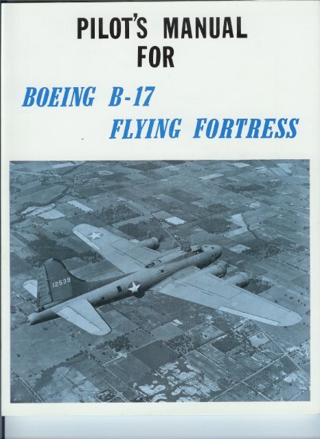
PILOT'SMANUALFORBOEINCB-<strong>17</strong>. . FLYINCFORTRESS- ~ .. = .. =..
,-,-- .----~ .. -~c - SECTION~~IDESCRIPTION-Figure'~)::-~1 - B-<strong>17</strong>F in Flight-1. AIRPLANE.a. Model B-<strong>17</strong>F and G bombardment airplanes arefour-engine-midwing monoplanes. The approximateover-all dimensions are: length, 74 feet 9 inches;height, taxying position, 19 feet 1 inch; span, 103 feet9 inches.Q. ElectricallY operated landing gear, tail gear,wing flaps, bomb bay doors, and hydraulically operatedbrakes and cowl flaps are provided.c. The crew includes pilot, copilot, navig:J.tor, bombaraier,upper turret gunner, lower turret gunner, radiooperator,sidegunner(s),and tail gunner. The airplanecan be entered either through the main entrancedoor on the right side of the airplane justforward of thehorizontal stabilizer, or through the front hatch in theIbottom of the fuselage below the pilot's compartment.d. Defensive armament of the B-<strong>17</strong>F consists ofthree turrets, each mounting two .50 calibre machineguns, and five single flexibly mounted .50 mounted. 50calibre machine gunS, The B-<strong>17</strong>G has an additionalpower turret just below the nose of the airplane and controlledfrom the. bombardier's compartment.e. Provisions are made for loading 2000-pound orsmaller bombs on racks within the bomb bay, and onebomb, up to 4000 pounds may be carried under eachwing.~ Automatic flight control equipment is provided.2. POWER PLANT.~'. ENGINES. - The Wright model R-1820-97 engiIwsare air-cooled, nine-cylinder radial aircraftengines, equipped with integral reduction gears throughwhich the propellers are driven.Q. TURBOSUPERCHARGERS. -A type B-2 GeneralElectric turbosupercharger is provided for each engineto boost manifold pressure for take-off and highaltitudeflight. Superchargers are controlled by automatichydraulic regulators adjusted from the pilot'scontrol pedestal.Figure 3 - Power Plant.!;.. PROPELLERS. - The Hamilton standard threebladepropeller's are hydromatically controlled withconstant-speed and full feathering provisions.g. AUTOMATICENGINE CONTROL. - Should en.-gine control cables be shot away, four of the controlswill automatically assume predetermined positions:throttles, wide open; superchargers, 65 percent power;intercoolers, cold; and propellers, 1850 rpm. Functioningof the automatic control at one unit will notaffect placement of controls at other units, or ofsimilar controls on other engines.Figure 2Three-quarterRear View1
.....,''3. HYDRAULIC SYSTEM control panel is in the "AUTO" position, pressure isautomatically regulated by a pressure cut-out switch,starting the pump when pressure drops to 600 pounds~. SERVICE SYSTEM. - Hydraulic pressure foroperating brakes and cowl flaps is supplied by 1melectric motor-driven pump, or by an accumulatorwhile the pump is not operating.(1) When the hydraulic pump switch on the pilot's'UPPlYTANK'DRAIN -':~HAND'UM',"CUMULATOR,,F VENT!!I ~I,,-~«,L'J'_-"'_."""""""RE"RlCTION FITTING ~ /PRE55URE GAGE ~"mURE 'WITCH~mF "ALING COU' lIN G I,and stopping the pump when the pressure builds up to800 pounds. In case the automatic pressure switchfails, pressure may be maintained by holding the hydraulicpump switch in the "MANUAL" position. Arelief valve opens if pressure in the system reaches900 pounds.,~
WARNINGShould leakage occur in the hydraulic system,the pump must be stopped to prevent loss offluid. Remove the hydraulic pump switch fuse,in the station 4 fuse panel, or disconnect theelectrical receptacle at the pressure switch.(2) In some airplanes the hydraulic pump is controlledby an "ON-OFF" switch on the pilot's controlpanel. This switch must be "ON" to maintain pressureautomatically.b. EMERGENCYBRAKE SYSTEM.- A spare accumulatorand auxiliary metering valves provide emergencybrake operation. A red warning lamp on thepilot's instrument panel lights when pressure in theemergency system falls to approximately 700 poundsper square inch. To charge the emergency accumulator,open the manual shut-off valve. If a selective checkvalve is installed, place it in "SERVICING" position,unless it is lockwired in "NORMAL" position. (Theseunits are located on the right side wall at the rear of'the control cabin. See figure 5.) Build up 800 poundspressure in the system, then return the selective checkvalve to "NORMAL" position and close the manualshut-off valve.NOTEThe emergency brake system has been eliminatedfrom the later model airplanes.c. PRESSURE GAGES. - Pressure in the serviceana emergency brake systems is indicated by, twogages on the pilot's instrument panel.d. HANDPUMP. - A hand pump on the side wallat flie right of the copilot is used to supply pressurefor ground service operations, and to recharge theaccumulators if the electric pump fails.RETURN.LINE"'"METERINGVALVE :::::-
4. rUEL SYSTEM.The fuel system consists of four independent singleenginesystems as shown in figure 7. The fuel supplyfor one engine can be used for another engine only bytransferring fuel from one engine tank to anotherthrough the fuel transfer system. All fuel tanks arethe r-eU:"sealing type.~. FUEL BOOST PUMPS. - Electrically drivenfuel boost pumps, controlled by toggle switches on thecentral control panel, supply pressure required forengine starting, and supplement the engine-drivenfuel pumps for take-off and for high-altitude flight.The boost pumps are normally turned off after theclimb from take-off is well under way and startedagain at 15,000 to 18,000 feet to prevent vaporizationin the fuel lines to the engihe-driven pumps. Boosterpump pressure at engine No.3 fuel strainer is usedto supply the cylinder head primer.Q. FUEL SHUT-OFF VALVES. - Fuel shut-offvalves, controlled by switches on the central controlpanel, are installed in the fuel lines between eachbooster pump and fuel strainer, providing immediatestoppage of flow to an engine in case a line is severed.t~I,Figure7 - Fuel Flow D;agram~ ;;... '"0"" > -., ..,"" '"""" "".. 1:;:- "'..0~ 0 .~~~ ~ ~ """' ~..,.,~... - ..> .. -"' > ~ .."'.... >~~~ ~~~ ~ ~ I:~;:~" ~~~~~~~-,... ~",,~""..> ""~""XUJ~0'"~~0","'>~"'UJUJ"x"",,~o ...~~ .. 0""0.."'...>..~ "'-""~~... o~ ""-0" -.....~::~~~~~3~~ffi~ ~E~~~8~=~~>- -NUJ'"""UJ"'UJ~-""I.. "'~ "'m""->~""'""" ",..0"'"..""='"UJ """ m""..mXI-"""" -=0 ""> ~ffi5~3~::;"" 0>""-=x..o""=-""00""UJe~1(~zUJ-" ""..-........-~j !;1:->""""I--"'~~ ",,=-x"""""'-o>-u>< ..~ffi~~~;:!~~=;:!"">"""'~co"""'e.::.I I ! ! !1I ,. . .~ I ~II I !.,;.m"" 0~ '" ~ ao-0"""'" "'" -'" ..,0>......m N N0.. ....... 0 ~o""'o .'"~ao""'"."'NN"~ o =~ .,o 0N '"~~"!"-",""",,,,-NN ...~ 3~";"'--NN "...~ ~""u:~!!~~~... ~"'NN"NN'"~ =0- ~>< ....z: o>~ b\;9 :!~ ~ ~ t:.t:.ffi fd~..~~'"!!s~!>
IglepplybyIlherareivenI theforliven19ht.thertedtionsterlsed-offtrol~achiate'ed.c. PRIMER. - The cylinder head primer has positiOitScorresponding to each of the four engines, andan "OFF" position in which the primer handle islocked. To operate, push the handle down, turn thevalve to the engine position required, and then withdrawthe handle and pump the charge to the engine.IMPORTANTPressure from No.3 fuel booster pump is onthe suction side of the primer and overprimingwill result, if the handle is left in the withdrawnposition. Therefore, each priming operationmust terminate with the handle returned to thelocked position.Q. FUEL TRANSFER SYSTEM.(1) Fuel is transferred by means of an electricmotor-driven pump and two selector valves. Themotor switch and selector valve handles are in therear of the control cabin below the door leading to thebomb bay. Direct transfer can only be made acrossthe center line of the airplane. (See figure 8 for fueltransfer procedure.)WARNINGDo not use bomb bay valve position when bombbay tanks are not installed. It is recommendedthat a 6-inch length of hose, plugged at theouter end, be attached to tne bomb bay valveports.(2) An emergency hand-operated fuel pump,mounted on the rear bulkhead of the bomb bay, can besubstituted for the electric-driven transfer pump bydisconnecting the electric pump lines from the fueltransfer selector valves at the forward end of thebomb bay and connecting the hand pump lines. Thehand pump can also be used as a refueling pump.(See figure 60.)(3) Airplanes equipped with auxiliary wing fuelcells have shut-off valves in the iines leading fromeach group of cells. These valves are controlled byhandles in the radio compartment or in the bomb baynear bulkhead No.5. (See figure 59.) Keep auxiliarycell shut-off valves "CLOSED" (handles out) at alltimes except when transferring fuel from auxiliary tomain tanks. Transfer fuel onlvwhen fuel level of maintanks has dropped to 100 I{allons per enl{ine. Aftertransfer, return valve to "CLOSED " (handle out)position.DESIREDTRANSFERFLOWPATTERNLEFT HAND TO RIGHT HAND TAN'EXAMPLEHAND BOMB FROM LEFT BAYTO ENGINE NO.' TANKLEFT HAND TO LEFT HAND TANK( TWO TRANSFERS REOUIRED)~~0-~EXAMPLE.FROM LEFT HAND BOMB BA'TO ENGINE NO. I TAN' BYWAY OF RIGHT HAND BOMB BAYTANK I::;:;;RIGHT HAND TO LEFT HANO TAN'EXAMPLE.RIGHT HAND BOMB FROM BAYTO 'NGINE NO 2 TANKRIGHT HANO TORIGHT HAHO TANK'TWO TRANSFERS REOUIRED 1~FROM ENGINE NO 3 TOENGIN' NO.' TANK BY WA
6. ELECTRICAL SYSTEM the ground to provide auxiliary electric power forrecharging batteries and for limited radio operation.a. A 24-volt d-c system distributes power fromfour engine-driven generators and from three storagebatteries in the leading edges of the wing, just outboardofthe fuselage. Three solenoid-operated batteryswitches are controlled by toggle switches on thepilot's control panel.b. A gasoline engine-driven generator unit stowedin tlie rear fuselage compartment may be operated on~. Alternating current for the Autosyn instruments,drift meter, radio compass, and warning signals transformeris furnished by two inverters under the pilot'sand copilot's seats. A double-throw switch on thepilot's control panel selects the inverter to be used:in "NORMAL" position the left inverter is on; in,"ALTERNATE" position the right inverter is on. Bothinverters are off when the switch is centered.SHIELD NO 30..-9313-2SHIELD NO 79~LOWER SIDE WALLSTA..A L.H.SHIELD NO.U'LEn FRONT5'DESTAT'ON .SHIELD NO. 78( "","" CO", lOA)CQ:::::::CD~."T. -, ,. L - (""."Ln' "'-'OA''-I..SO"'- '.'8983-37'-7.3'""-"""'" ,SHIELD NO.3STA. 3 R. C.RECEIVER SUPT.NOTE:FUSES FOR 100'REPLACEMENTCARRIEDINSIDE OF SHIELDS,
7. HEATING~. GLYCOL HEATING SYSTEM. - Cabin heat issupplied by a hot air system in which heat is transferredto the ventilating air from a glycol system inthe No.2 nacelle. Flow of heated air to the cabin iscontrolled by a damper at the pilot's left. Defrosterair is controlled by a red knob in the "v" of the pilot'swindshield and by a control near the outlet in thebombardier's air duct. Fill glycol tank with approvedmixture only; do not dilute with water.CAUTIONDuring starting and ground operation of engines,the cabin heat control must be in the "OFF"or "COLD" position to prevent glycol in thesystem from boiling away.b. AUXILIARY HEATING SYS-TEM. - A similar glycolsystem,installed in the No.3 nacelle ofsome airplanes, supplies eightradiator-fan heating and defrostingunits in various locations inthe airplane. Fan motors arethermostatically controlled andthe flow of heating air is regulatedby a damper at each unit.c. SUIT HEATER OUTLET. -Tenreceptacles for plugging in elec- .tric suit heaters are provided atvarious crew stations. The heatoutput of each suit is controlledby a rheostat on the receptaclebox. .Figure 12 - SUit Heater Recep tac Ie8.::" Heat ing & Vent i h.t ingSystem DuctsG1yco1 System LinesVentCONTROL SETTING VANE POSITIONSCONDITIONWHEN ODNTROLHANDL.POSiTIDNS ARE AS SHOWNBY SOLIO UNES.* I. FULL OUTPUT OF HEATING SYSTE..ENTERSCABIN.2. COLD AIR INLET a.OSED.3. HOT AIR GIRCULATION IN CABIN.HOT* I. FULL OUTPUT OF HEATINGSYSTE"SPILLS OVERBOARD.2. FULL VOLU"E OF COLD AIR ENTERSCABIN.COLD3. COLD AIR cuiCULATION IN CABIN.* ,. FULL OUTPUT 'OF HEATING SYSTE"SPILLSOVERBOARD.2. COLe AIR INLET a.OSED.OFFCABIN AI.3. NO C'RCULATION IN CABIN.*TM£ G\.YCQI. SYST... """ATES COOTINUOUSLYR",RIX.US OF THE POSIYlON OF HEAT'NG CONTROLS. THE FLOW OF HOT AIR IIIIST THEREFORE BE UN-RESTRIOTED TO PRE-_T DAMAGETO THE GLYCOLSYST"'.Figure11 - Heating System Diagram8------------------
~ /8. VACUUM AND DE-ICING SYSTEMVACUUMWARNING---SWITCH 0/WING DE-ICER VALVE/po~ o~"9C", \ /K 0", / /(00~Jl/E,--- 0;~_m ~_~-- ~~/-:-:;:::;i O, DO" /' "6/ H FE \, : TO '-TO CRANKCA" . DE-ICER VALVE CONTRO'I~::' ""-ICER PRESSUR "N"I" ' ' EGAGE",,/ : TO PUMPSY I i ~ ' TO SE, ' ' A I ' LECTOR VALVEI TO BATTERY 'y' 1" "'-1 ~r-oTO I!Jr°BATTERY/9 STA.4~ PANEL . - - ~ - -- -.. "'N --'f~'~-r:""""" .~ ~ """'I1".Ii,",IIII:"- BY PASS OVERBOARO/1"- DE-ICERS "OFF" ~RAINI\')~I,---~-- :'." -~ ~::~- -"_..... ,'-- ---"! I: I I.':II II II I II \ IFICVACUUMPUMPVACUUMPUMPL.~ R.G~INSTRUMENTSVACUUM SELECTORVALVEOK"VACUUMLINES PRESSURELINES " ELECTRICALWIRINGFigure 13 - Vacuum and De-leer Flow DiagramA - SUCT I ON GAGEI - OIL SEPARATORB - DE-ICERPRESSURE GAGEC - SUCTIONRELIEF VALVED - CHECKVALVEE - OIL SEPARATORF - PRESSURERELIEF VALVEG-ROTARYDISTRIBUTINGVALVEH- TESTCONNECTIONKEY TO fiGURE 13J - MANIFOLD(INSTR. TUBIN~K - SELECTORVALVEL - VACUUMPUMPM - SHUT-OFFVALVEN - DE-ICER CONTROLVALVE0 - PRESSURE -RELIEF VALVEP - SHUT-OFFVALVEQ - VALVE:",- NO'-B~-~; ~I~~~,_.. --)OE -ICERS ON- DE-ICERS"ON"-Vacuum pumps are driven by engines Nos. 2 and 3.The selector valve on the side wall at the left of thepilot permits selection of either pump for deflation ofde-icer shoes and at the same time provides the useof the other pump for all other vacuum-operated equipment.When the de-icer control valve is "ON," itdirects the discharge of both vacuum pumps to the deicerdistributor valve and also starts the distributorvalve motors. When it is "OFF" the exhaust fromboth pumps is bypassed overboard, and the distributormotor is stopped.9
9. OXYGEN SYSTEMuBOMBARDIERCO-PILOT ..........TOPGUNNERNAVIGATOR-. IPILOTI,:I.I '---" .J: \ ;~ -t--_L L___--_-----BRITISH ADAPTER'iI-TAILGUNNERID- CYLINDER$AT LEFTSIDE OF COCKPIT(1)- CYLINDERSAT RIGHT SIDE OF COCKPIT~- CYLINDERSUNDERPILOT'S FLOORCQ) - CYLINDERSUNDER RADIOCOMPARTMENT FLOOR(]I) - TURRET CYLINDERS.~REGULATOR,TYPE A-12REGULATOR,TYPE A-9ADI STRIBUTI ON LINEFI LLERSYSTEMFLEXIBLEFILLERSYSTEMFigurea. SUPPLY SYSTEM. - Breathingoxygen is storedin fS type G-l cylinders and is distributed by fourself-contained systems, each serving two or more crewstations, which prevent complete loss of supply shoulda distribution line be severed. A check valve at eachcylinder prevents loss of system pressure through apunctured cylinder. Each fully charged G-l cylinderwill supply one man with oxygen for 5 hours at 30,000feet. The main system is filled to 400 pounds persquare inch pressure through a filler valve just aft ofthe forward entrance hatch. On some airplanes aseparate type F-l cylinder at each power turret provides2-1/2 hours of oxygen for one man at 30,000feet and is refilled from the main system through avalve on a flexible hose. (See figure 15) Portableoxygen units provided for each crew member may befilled at the recharging valve at any demand regulator.14 - Oxygen Flow DiagramNOTEIn some airplanes 15 constant-flow type A-9Aregulators are provided. This installation hasa relief valve in the filler system, and doesnot have the indicator panels or the portableunits, but is essentially the same as the demandsystem.Q. REGULATORS. - Atype A-12 demand regulatorand an indicator panel are located at each crew station.(See figure 16 for operation.) Power turrets areequipped with A-9A constant-flow regulators in airplaneshaving separate turret cylinders.c. INDICATOR PANELS. - When oxygen flowsfrom the regulator, the ball in the indicator bouncesup in the glass tube; when flow stops, the ball falls.Do not be surprised if the indicator shows no oxygenflowing when the airplane is on the ground and theauto-mix is "ON," as the regulator is not necessarilysupposed to add oxygen at ground level. The gageshows the pressure in the supply cylinders for thatstation. The warning signal lights when that pressurefalls below 100 pounds per square inch.10Figure 15 - Refilling Turret Oxygen Cylinder 1.fi12.pc
IIiTEM'ILLER9Aas,es)le,e-USB OXYGBNFor normal operation the" Auto-Mix"should always be turned to "ON"position as shown here. This assuresa proper mixture of oxygen with theoutside air. When" Auto.Mix" is"OFF" the regulator will furnish pureoxygen on demand.INTB..LIGBNT..'YU,.p'op."y fitt.d mall o..clfa, '.oh byholding,humbov.,mo.1 ho..; dl,conn.,' Rtt'n.ond ,.hol. .ormolly.< .~S~.y~'~/P,'o,'0 tnoh'.Iw.y. chod'hi. burl.dcoli..,I'm'"b. TIGHT.To get oxygen, place the endconnection of mask hose into thefitting, on end of feede, hosecoming from the DemandRegulator.3. Check to see that there is a portable "walk-around"unit at each station, filled to 400 pounds, and in workingorder.4. Check system pressure before flight; it should be400 pounds.5. Check function of demand regulator in both "ON"and "OFF" positions. Flow gage should function whenauto-mix is "OFF."6. Check knurled collar on elbow connecting mask,hose to regulator for tightness.7. Open emergency valve to check flow; then close.This valve should not be open except in case of emergency.8. Turn regulator to auto-mix "ON" position.9. Use auto-mix "OFF" only -When oxygen officer advises the use of pure oxygenbefore take-off, in which case, use it all theway up as protection against "bends."When treating men for shock, loss of blood, or asprotection against poisonous gas.10. Start using oxygen at 10,000 feet. At night useoxygen from ground up, with auto-mix in "ON" position.11. In flight above 10,000 feet, always use "walkaround"unit when moving from one station to another.If Regulator fails to function, tu,n onEmergency Valve. This allows a constantflow of oxygen to the mask.di,ect from the supply line. Flow in.dicato, will not operate under thiscondition, ond oxygen will flow fromthe supply line at a higher ,ate.Watch your p,essu,e gage.!)~Figure 16 -Use of OxygenCAUTIONEXERCISE EXTREMECAUTION TO INSURE THAT OXYGENEQUIPMENT DOES NOT BECOME CON-TAMINATED WITH OIL OR GREASE.FIRE OR EXPLOSION MAY RESULTWHEN EVEN SLIGHT TRACES OF OILOR GREASE COME IN CONTACT WITHOXYGENUNDER PRESSURE.1. Have your own mask which has been checked forfit by the oxygen officer.2. Carry your bail-out cylinder charged to 1800pounds.To use portable unit;first: Check pressuregage of portable unit;2nd: Inha Ie deeply,then disconnect maskfrom regular hose andquickly open springcover of regulator connectionand snap inmale fitting on end ofmask hose. Clamp port~able unit to clothing.DON'1 DELAY-When pointer on pressuregage reaches redarea refill cylinder.Figure <strong>17</strong> - Portable Oxygen Unit in Use11
I.L--MAN HOURS OF AVAILADLE OXYGENBLACK FIGURES INDICATE AUTO-MIX "ON" RED FIGURES INDICATE AUTO-MIX "OFF"CAUTION- The autO-mix in the off position rapidly diminishes theavailable oxygen supply. Do not use this position unless it is necessaryto get pure oxygen!AIRCOREGULA TORSTYPE A-12A, (PIONEER REGULATORSTYPE A-12A....~---~"'ẉ......"'0""C ::I:::1-'0.Uo-I-
MAN HOURS OF A V AILABLE OXYGENBLACK FIGURES INDICATE AUTO-MIX "ON"RED FIGURES INDICATE AUTO-MIX "OFF"NOTE: Each turret cylinder, Type F-I, will supply one man for approximately2 hours at 30,000 feet, 2 Y2hours at 25,000 feet, 3 hours at 20,000feet.IAIRCOREGULA TORSTYPE A-12A"OS ~ 4.8 4.1 3.4 2.7 2.1 1.4 0.710,000 29.1 25.0 20.5 16.6 12.3 8.4 4.0NGagePres.Alt..400 350 300 250 200 150 100 50Ft...: "49.8 42.8 35.4 28.4 21.4 14.4 7.0'"c~:I="E40,000 49.8 42.8 35.4 28.4 21.2 14.4 6.9:,,~35.4 30.4 25.0 20.2 15.2 10.2 5.0""...-C-c " 35,000 35.4 30.4 25.0 20.1 15.1 10.2 4.9M.S(jjt:":I25.8 22.2 18.2 15.6 11.0 7.4 2.8U"'f-
"'.,'"....-..-10. COMMUNICATIONS EQUIPMENT~. GENERAL. -, A radio and interphone systemprovides for communications between crew memberswithin the airplane; between the airplane and groundstations or other airplanes; reception of weather,range, and marker beacon signals; and ground andinterphone identification.Q. INTERPHONE SYSTEM. - Interphone jack boxesare installed at 11 locations in the airplane. With!!!!yselector switch in "CALL" position, that station maybe heard at all other stations regardless of the positionof their selector switches. With all switches adjustedto "INTER," any station may be heard at all otherstations. Any station may listen to the liaison, command,or radio compass receiver by adjusting theselector switch to those positions. Any station canmodulate the command radio transmitter; however,modulation of the liaison transmitter is provided forpilot, copilot, navigator, and radio operator. All stationsare provided with throat microphones, which,with the exception of thosefor the pilot and copilot,"ire controlled by "PUSH-TO-TALK" switches onthe cords. They are connectedto the jack boxesby extension cords.£. OTHER COMMU-NICATIONS EQUIPMENT.Instructionother comfor operatingm u n i cat ionequipment will be found inthe section covering thecompartment in which theequipment is located.~,..e .......Figure 18InterphoneJack BoxIII-~~ \)~~ - - - - \!C "3/I I/ I~ ~ ""'""'~ , I(- ~ ~ ' ~C- /' '-~u;iT 6 ,1/ /"- ""- y' ""-6C\ (" "', />/ "8)0/ --- "'\. ' "'-:6 ~,~~""- /=~ ~.>-- / , ,., . - W /' ~~ :;;;-, ~ ~ ""'"// / _/ . ,/ ","",' ~r( ,-:-- T-' ~\ ,"'' // / ~' ",,'."," '" 0-000' '" .-, " / / ~ ""~.. ~:' ,.,.., '- , ::" """oi.. ' .,INTERPHONE R' 3 a 4 RESPFigure 19 - Communications Equipment14
I. RESTRICTIONSWARNINGSome airplanes are restricted.DON'Tlower flaps at speeds in.xcess of 147 mph!DON'T dive in excess of 270mph (with modifled elevatorsl.to 220-mph maximum divingspeed, pending modiflcation ofthe elevators. See warningplacard in airplane.DON'T exceed 46 inches Hgmanifold pressure!DON'T exceed 30 inches Hgbelow 2100 rpm!DON'T roll!CAUTION. ..All power seHings given in thisseclion are for use with 100oclane fuel only. See appendixIII for restridions to b. ob-DON'Tloop!DON'T aHempt inverted Right!DON'T fly the airplane at maximumgro55 weight 164,500pounds! UNLESSauxiliary wingtanks are full!served when using 91 oclanefuel.RESTRICTED15
,';.~,..--2. OPERATIONAL EQUIPMENT~. CENTRAL CONTROL PANEL AND PEDESTAL.(1) WING FLAP AND LANDING GEAR CON-TROLS. - The wing flap motor is controlled by atoggle switch. The time required to lower the flapsat 147 mph is between 15 and 30 seconds.WARNINGIn returning the flap control switches from"DOWN" to "OFF," be sure the toggle switchis not allowed to snap to "UP," resulting inimmediate retraction of the flaps.(2) The main landing wheels and tail wheel areoperated simultaneously by a toggle switch. A hingedguard prevents accidental moving of the switch to the"Up" position. Warning that the landing gear is notfully extended is given by a green indicator lamp failingto light, and by a horn which sounds if any throttleis closed.(3) COWL FLAP VALVES. - Cowl flaps are operatedby four valves, each valve controlling the flapson one nacelle. The valve must be turned to "LOCKED"when the desired position of the' flaps is reached.Slight "cracking" of the control valve will result inrelatively slow travel of the flaps when close adjustmentis desired.(4) FUEL BOOST CONTROLS. - The fuel boostpumps, operated by four toggle switches, provide fuel@KEY TO FIGURE21I. IG"ITION SWITCHES2. FUELBOOST PUMPSWITCHES3. FUEL SHUT-OFFVALVESWITCHES~. COWLFLAP CONTROLVALVES5. LANDINGGEARSWITCH6. WINGFLAP SWITCH8. TURROA"D MIXTURECONTROLLOCK9. THROTTLE CONTROLLOCK10. PROPELLERPITCHCONTROLSII. PROPELLERPITCHCONTROL LOCK12. THROTTLE CONTROLS7. TURBOSUPERCHARGER13. MIXTURECONTROLSCONTROLSFigure 21 - Control Panel and Pedestalpressure for starting engines and for maximum power,and also prevent vaporization in the lines to enginedrivenpumps due to hot fuel or high altitudes. Booster.pressure at the No.3 nacelle fuel strainer also suppliesfuel to the priming system.16
BLOCKe- COMPASSr£\ CA~-'" ~~ AI~Cli'l~PARK 1.0 BBm c'o
.-. ~Ir--Figure 22 - Controls at Pilot's Left,II,,I KEY TO- fIGURE 22I'II. PANELLIGHT2. PANELLIGHTSWITCH3. PILOT'S SEATq. FILTER SELECTORSWITCH5. PROPELLERANTI-ICERSWITCH6. I NTERPHONEJACKBOX7. OXYGENREGULATOR8. WINDSHIELDWIPERCONTROLS9. PORTABLEOXYGENUNIT RECHARGER10. WINDSHIELDANTI-II.ICER SWITCHWINDSHIELDANTI-ICERFLOWCONTROL12. PROPELLERANTI-ICERRHEOSTATS13. SURFACEDE-ICERCONTROLIq. AILERONTRIM TABCONTROL15. PILOT.'S SEATADJUST-MENTLEVER16. AilERON TRIM TABINDICATOR<strong>17</strong>. CABIN AIR CONTROL18. SUIT HEATEROUTLET19. VACUUMSELECTORVALVE20. EMERGENCYBOMBRELEASEserve this precaution may cause detonation and eventualengine failure or sufficient overspeeding of theturbo wheel to cause serious damage.@ Filters must be "ON" before landing, sincethe supercharger control levers were adjusted for amaximum manifold pressure at take-off with the filters"ON." If emergency power is attempted with thefilters "OFF," manifold pressures above the recommendedmaximum of 46 inches will be obtained.(2) OIL DILUTION SWITCHES.~ Four momentary contact toggle switches onthe side of the copilot's auxiliarynoid valves in the correspondingpanel operate so\e-nacelle, admittingfuel to the engine oil in line. This operation is performedAFTER an engine run, immediately prior toshutting it off.(Q) Do not dilute oil over 4 minutes. The superchargercontrols should be operated continuouslyduring this period to cause diluted oil to flow to theregulators. The propeller control should be moved18
IF'from extreme increase to extreme decrease rpmslowly several times to fIll the propeller dome withdiluted oil and prevent sluggish response of the propellerwhen starting the engine.(3) STARTER SWITCHES. - Two START and twoMESH switches control the engine starters. TheSTART sWItch energizes the starter motor, rotatmgthe mertia flywheel. The MESH sWItch engages thestarter and engine jaws while the START switch isheld on.NOTESome airplanes have a "START-OFF-MESH"switch for each engine starter.(4) PARKING BRAKE. - The pull handle at thebottom of the instrument panel sets the copilot's brakemetering valves when the foot pedals are depressed.This utilizes the regular braking system; therefore,hydraulic system pressure must be available whenthe parking brake is required for any length of time.When necessary, set the parking brake handle andpump the system pressure to at least 400 pounds persquare inch (minimum pressure for full braking control).WARNINGDo not set parking brake while brake drumsare hot.(5) FUEL INDICATOR. - A liquidometer indicator,on the extreme right side of the instrument panel,shows the available fuel supply in anyone of the sixmain fuel tanks. A six-position switch directly belowthe indicating dial, selects the tank to be checked.(6) INSTRUMENT LIGHTING.(a) Three spot lamps light the instrument paneland a fourth on the ceiling lights the compass panel.Two types of light are available: for flood lightingwith visible fluorescent light, rotate the shutter to theleft; for ultra-violet activation of the luminous painton the instrument dials, rotate the shutter in the oppositedirection approximately one-quarter turn.(b) The spot lights are controlled by switches,two on-the pilot's instrument panel, and one on thecopilot's auxiliary panel. To operate, hold the switchin the "START" position for approximately 2 seconds;then, release the switch allowing it to spring back tothe "ON" position.c. CONTROLSAT PILOT'S LEFT.(1) CABIN Am CONTROL. - Heat and ventilationare controlled by a lever on the side wall. (See figure11 for operation.)CAUTIONBe sure the heater control is "OFF" or"COLD" for all startmg and ground operations.(2) VACUUM PUMP CONTROL. - The' 'GYROINSTRUMENTS" selector valve on the side wall permitsuse of eIther vacuum pump for the gyro instruments,suction from (Ii(' other pump bemg connectedto the surface de-Icer syst('m. (See figure 13.)(3) DE-ICER CONTROL. - The de-icer valve onthe floor panel controls the operatIon of the surfacede-icer shoes. In the "ON" position It starts the deicerdistributor and connects the exhaust pressurefrom both vacuum pumps, and the suction from onevacuum pump to the distributor valve. In the "OFF"position the distributor motor is turned off and thepressure from the vacuum pumps is bypassed overboard.Suction reniams connected to the distributorvalve in order to keep the de-icer shoes deflated.(4) PROPELLER ANTI-ICER CONTROL. - Atoggle switch on the side wall controls the two propelleranti-icer pumps. Two rheostats on the floorpanel control the speed of the pump motors and maybe used to turn the motors off if desired. Normallythe rheostats should be left adjusted to a predeterminedrate of flow and the pump motors turned on or off bymeans of the toggle switch.(5) WINDSHIELD WIPER AND ANTI-ICER. -Windshield wiper and anti-icer controls are on apanel at the pilot's left.(a) A toggle switch controls the operation ofthe wiper motor, "OFF," "SLOW," or "FAST," anda circuit breaker is provided to protect motor in caseof an overload.(b) An "ON -OFF" switch controls the alcoholpump, and flow is regulated by a needle valve.CAUTIONDo not operate wipers on dry glass!(6) EMERGENCY BOMB RELEASE. - An emergencybGmb release handle is at the pilot's left. Pullingthe handle immediately releases bomb door latches,and continued pulling will release all bombs SALVOthe instant the doors are fully open. Bomb bay fueltanks may be dropped by the release handle.d. PILOT'S CONTROL PANEL.(1) ALARM BELL CONTROL. - A toggle switchoperates three alarm bells: one under the navigator'stable, one above the radio operator's table, and onein the tail wheel compartment inside the dorsal fin.(2) PHONE CALL. - Another toggle switch operatesfour amber phone call signal lamps: three ad-19
."'r-INVERTERNORMALr~~AL TERNATEi§)PITOT L.GEARONWARN.~FF II ~FH~ATWARNINGIn case of leakage stop the pump to preventloss of fluid. Remove switch fuse at station4 fuse panel or disconnect receptable at switch.In some airplanes the hydraulic pump is controlledby an "ON -OFF" switch.(7) CARBURETOR ANTI-ICER.(a) Carburetor icing may occur in outside airtemperatures up to 500F (1 OOC), with humidity greaterthan 50 percenC Ice formation in the carburetoradaptor or at the fuel nozzle, indicated by engineroughness and a drop in manifold pressure, may beeliminated by moving the intercooler shutters to"HOT," or by setting the turbos "FULL ON" andadjusting power with the throttles. Apply full powerand climb above icing condition if possible. Below15,000 feet the air filters may be opened to providea further increase of carburetor air temperature.WARNINGBATTERY~ ON OFF~4"" "~""CO",.,," """'"',' eo",'"'"0,'"" .. '"" """', ,.",",WJOFF ON( POSmON LIGHTS)Figure 23"- Pilot's Control Paneljacent to the alarm bells, and the fourth at the tailgunner's right.(3) BOMBARDIER CALL. - A toggle switch onthe pilot's control panel operates an amber call lampon the bombardier's control panel; and a toggle switchon the bombardier's panel operates an amber calllamp on the pilot's instrument panel.(4) LANDING GEAR WARNING HORN RESET. -A switch on the control panel permits the silencingof the landing gear warning horn when it is desiredto continue flight with one or more throttles closed.Operation of this switch does not prevent repetitionof the warning for subsequent closing of any throttlewhile the landing gear is up. The switch is reset whenthe throttles are opened.eDO NOT EXCEED ALLOWABLE LIMITS FORMANIFOLD PRESSURE, ENGINE RPM, ANDCYLINDER HEAD TEMPERATURE.(b) Some airplanes are equipped with carburetoranti-icers consisting of pumps controlled by toggleswitches on the pilot's control panel. One suppliesinboard engines; the other, outboard engines. Approximately4 gallons of isopropyl alcohol per hourare sprayed into the pressure duct of each carburetor,the entire system sustaining a total of 2 hours operation.This equipment should be used as follows:1. To start an engine after severe carburetoricing or-engine stoppage.2. Todetermine cause of power loss or engineroughness; if adjustment of engine controls and use of-.ARMOR PLATESUPPORT(5) INVERTER SWITCH. - A double-throw switchselects which of two inverters is to be used: in"NORMAL" position the left inverter is on; in "AL-TERNATE" position the right inverter is on.(6) HYDRAULIC PUMP SWITCH. - With thisswitch in the "AUTO" position, pressure is automaticallyregulated between 600 and 800 pounds. Incase of failure of the automatic pressure, cut-outpressure may be maintained by holding the switch inthe "MANUAL" position.Figure 24 - Pilot's Seat Adjustment20
eair~ater'etorIgineIYbe5 toandJwerelow)Vide'etorggleJliesAphouretor,era-'etorIginese ofalcohol system does not relieve condition, it can beassumed the trouble is not caused by icing.3. To clear out engines quickly after a glideat low power through icing conditions.!. To obtain full power under icing conditions.5. As an alternate method of ice elimination ifuse of fuel turbo or carburetor air filter is prohibited.f. TRIM TAB CONTROLS.e. DEFROSTERCONTROL. -Hot airfor defrosting thepilot's and copilot'swindshields is controlledby a red buttonin the vee of thewindshield.(1) Complete aileron tab travel requires about3-3/4 turns of the knob located on the pilot's floorpaneL(2) Complete rudder tab travel requires abouts~ven turns of the wheel located on the floor in fronto~the control pedestal.(3) The elevator trim tab wheel on the left sideof the control pedestal requires about six turns forcomplete travel. It has a friction brake to preventcreeping.~. LOCKS.(1) AILERON LOCK. - The aileron is locked inneutral position by a pin which is manually insertedin a hole in the left control column, holding the centerspoke of that wheel in a padded slot. The pin is clippedto the pilot's control column when not in use.(2) RUDDER AND ELEVATOR LOCK. - Therudder and elevator locking lever operates by cablecontrol to place a pin in a socket on a segment ateach of the control quadrants. The locking lever,which is recess'ed into the floor aft of the enginecontrol pedestal, is locked in either the "Up" or"DOWN"position. The lever may be moved to the"Up" or "LOCKED" position, regardless of theattitude of the control surfaces. Under this condition,the control surfaces will automatically lockwhen the rudder is in the "NEUTRAL" position andthe elevator is in the "DOWN" position.(3) TAIL WHEEL' LOCK. - The tail wheel lockingleveroperates a single cable to retrace a springloadedlockingpin from a socket in the treadle. Thelocking lever which is recessed into the floor aft ofthe control pedestal, latches in the "Up" positiononly and may be moved into the "DOWN" positionregardless of the attitude of the tail wheel, whichwill lock when centered. To release the locking handle,press the knob on the end of it. A .red signallight on the pilot's instrument panel is "OFF" whenthe tail wheel is locked.h. AUTOMATIC FLIGHT CONTROL EQUIPMENT.The automatic flight control panel is located on thefront of the control pedestal. To engage A.F.C.E.:(1) Throw "ON" master and stabilizer switches.(2) CAREFULLY TRIM AIRPLANE FORSTRAIGHT AND LEVEL FLIGHT.(3) Turn "ON" tell-tale lights.(4) After master and stabilizer switches havebeen "ON" for 10 minutes, throw "ON" PDI and servoswitches.(5) Center PDI by turning plane and resumingstraight and level flight.Figure 25 - Lower Control Pedestal21
ARHOR PROTECTS PILOTSfROHU.S. .30. GERH".312.IT'"", J"-"ESE .303 (7.7 HH,C'II BER FI RE O" G-INATINGWITHIN W"[TEAREAS.--Figure 26 - Pilot's Armor Protection(6) With PDI on "ZERO," adjust rudder centeringknob until both rudder tell-tale lights go "OUT."Immediately throw rudder switch "ON.'"(7) With wings level, adjust aileron centeringknob until both aileron tell-tale lights go "OUT."Immediately throw aileron switch "ON."(8) With airplane flying level, adjust elevatorcentering knob until both elevator tell-tale lights go"OUT." Immediately throw elevator switch "ON.", (9) Observe PDI, artificial horizon, and rate-ofclimbor altimeter instruments. Then carefully retrimall centering knobs, until ship is flying as straightand level as possible, with PDI on "CENTER."(10) With autopilot engaged, all course correctionsmust be made with turn control ONLY. Always turnknob with a slow steady movement.WARNINGDo not engage A.F.C.E. motors until all "telltale"lights are off.Figure 27 - Controls at Copilot's RightI. HYDRAULIC HAND PUMP2. CHECKLI ST3. INTERPHONESELECTORSWITCH~. INTERPHONEJACKBOX5. FILTERSELECTORSWITCHKEY TO FIGURE276. COPILOT' SEAT7. RUDDERPEDALADJUSTMENT8. COPILOT'SCONTROLWHEEL9. INTERCOOLERCONTROLS10. SUIT HEATEROUTLETII.ENGINEPRIMER22
.,b CONTROLS AT COPILOT'S IDGHT.(1) PRIMER. - The cylinder head primer hasfour positions corresponding to the four engines, andan "OFF" position. The primer handle is lockedonly in "the "OFF" position. To operate, push thehandle down, turn the valve to the engine positionrequired, and then withdraw the handle and pump thecharge to the cylinder.IMPORTANTOverpriming will result if the handle is leftin the withdrawn position. Therefore, eachpriming operation must terminate with thehandle returned to the locked position.(2) CARBURETORTEMPERATURE CONTROLS.The intercooler shutters are controlled from a standin front of the copilot. Each cable is operated by aslide latching in any desired position. To releasethe latch, pull handle out.(3) HYDRAULIC HAND PUMP. - The hydraulichand pump is manually operated to furnish pressurein case of failure of the electric punip.(4) KEY CASE. - A key case on the side wallcontains two keys which fit all door locks in the airplane.i.. RUDDER PEDAL ADJUSTMENT. -Rudder pedaltilt may be varied to any of five positions by a lockingpin and sector at the outside corner of each pedal.~. PILOT'S COMMUNICATIONSCONTROLS.(1) GENERAL.@) All communications equipment may be operatedto some extent from the pilot's compartment.Receiver and transmitter frequency selection may becontrolled with the exception of the liaison equipmentwhich must have ~oth its transmitter and receiverfrequencies set by the radio operator.CAUTIONFor normal operation of all communicationsequipment, the filter selector switch should beset at "BOTH." To receive the radio rangewithout possibility of voice interference, setthe selector switch to "RANGE." To receivevoice without range interference, set selectorswitch to "VOICE."NOTEThe head set extension cord should be pluggedinto the filter selector control box as shownin'figure 28 and not into the interphone jackboxor the receiver control box.NICROPHOME PLUGHEADPHONESPLUGFigure 28 - Microphone and Headset PlugsIMPORTANTWhen the throat microphone is being used foreither interphone or-radio communication, itmust be adjusted so that its two circular elementsare held snugly against each side of thethroat just above the "Adam's apple." SPEAKSLOWLY, DISTINCTLY, AND IN A NORMALTONE OF VOICE. Shouting will seriously distortthe voice signal.(Q) A possible means of limiting noise level inall radio equipment, caused by adverse conditions suchas rain, snow, ice, or sand, is to direct the radio operatorto proceed as follows:1. Place the antenna change-over. switch to thefixed antenna position.~. Release approximately 50 feet of the trailingwire antenna.~. Ground the trailing wire antenna post directlyto. the airplane structure (for instance, themetal support for the transmitter tuning units).Do not extend retractablegreater than 240 mph.CAUTIONrod antenna at speeds(2) INTERPHONE EQUIPMENT RC-36. - An interphonejack box is provided for both pilot and copilot.Refer to section I, paragraph 10.(3) COMMAND SET SCR-274-N. - The commandset is designed for short-range operation and is usedfor communicating with nearby aircraft for tacticalpurposes and with ground stations for navigational andtraffic control purposes.(!0 RECEIVING. - The interphone jack box (figure22) switch must first be placed in the "COMMAND"position. The" receiver control box (figure 29) isdivided into three sections, each controlling the par-23
:dKEY TO FIGURE 29I. COMMANDRECEIVERCONTROLUNIT2. LOOPCO"TROLSWITCH3. LIGHT CONTROLSWITCHq. VOLUMECONTROL5. CONTROLINDICATORLAMP6. BANDSELECTORKNOB7. POWERSWITCH8. TUNINGCRANK9. CONTROLPUSHBUTTON'10. TRANSMITTINGKEYI I.TRANSMISSIONSELECTORSWITCH(TONE-CW-VOICE)12. TRANSMITTERPOWERSWITCH13. CHANNELSELECTORSWITCHIq. A-B CHANNELSWITCH15. SIGNALSELECTORSWITCH16. VOLUMECONTROL<strong>17</strong>. TUNINGCRANKtfFigure 29 - Radio Controls,Pilot's Compartment Ceilingticular receiver to which it is connected. Receptionof a signal.of a specific frequency as indicated on thedial is accomplished by the use of the section of thereceiver control box which controls the particular receiverinvolved. The desired receiver is turned onand off by a switch in the left forward corner of thecontrol box section used. This switch, in addition tohaving an "OFF" position, has two selective positionsmarked "cw" and "MCW," which indicate thetype of signal which is to be received. The "A-B"switch should be left in the "A" position at all timesand need not be turned off when the receivers areturned off.NOTEWhen tuning receiver for a definite frequency,always turn dial a little to each side of the frequencycalibration mark to find the point wherethe signal is the strongest. .(Q) TRANSMITTING.1. Before transmitting, adjust radio receiverto the same frequency as the station with which youdesire to talk, and listen in to be sure that the operatoris not talking to someone else. If the station is transmitting,take advantage of the opportunity to moreaccurately set the airplane receiver on the assignedfrequency, and when the other operator is finished,proceed with your transmission.!. Throw the "OFF-ON" switch ~figtire 29)on the transmitter control box to the "ON' position.Select type of transmission desired with switch marked"TONE -CW -VOICE." With the switch in the "VOICE"position, the microphone from any interphone jack boxswitched to "COMMAND" position. will be operativeand voice will be transmitted when the push-to-talkbutton on the control wheel is pressed. With theswitch turned to the "cw" position, a continuouswave, or unmodulated signal, will be transmitted andwith the switch in the "TONE" position, a modulatedtone signal is transmitted. Greatest effective rangecan be obtained on "CW." Range is most limitedwhen operating on "VOICE."3. On both the "cw" and "TONE" positions,the microphones are' inoperative, and signalling bycode is accomplished by a key which is located on theforward end of the transmitter control box.NOTETo reduce battery drain and to increase dynamotorlife, the "TONE-CW-VOICE" switchshould be left on "VOICE" unless continueduse on "cw" or "TONE" is expected.(4) RADIO COMPASS SCR-269.@) Set the interphone jack box switch (figure 22)to the "COMP" position, if aural reception of the24
adio compass receiver is desired. If only visual indicationis desired, the switch does not have to be setin the "COMP"'position.(Q) The radio compass equipment is designedto perform the following functions:1. Aural reception from the fixed antenna orfrom the rotatable loop. For signal reception duringinterference caused by prec ipitation static or proxim ~ity of signals, the loop will prove superior.~. Aural..null directional indication of an incomingsignal with the loop only in use.~. Visual unidirectional indication of an incomingsignal.(0 The receiving unit is turned on or off by aswitch on the face of the remote control box, which,in addition to having an "OFF" position, has threeother positions: "COMP," "ANT," and "LOOP."1. With the switch in the "COMP" position,both the rotatable loop and the fixed antenna are in use.~. In the position marked "ANT" only the fixedantenna is in use.~. With the switch turned to the "LOOP" position,only the rotatable loop is in use.(Q) If the green indicator ,on the face of the controlboxdoes not light, depress button marked "CON-TRoL" to establish control of the set at this unit.Select frequency band desired as indicated in kilocy~cles on the face of control box and tune by use of thecrank to the desired frequency. The loop may be rotatedtoany positionas indicated on the radio compassazimuth indicator by use of switch marked "LOOPL-R." (See figure 29.) This particular operation ispossible only when operating on "LOOP" position ofthe selector switch. During periods of severe precipitationstatic, operate on "LOOP." For best auralreception rotate the loop by means of the "LOOPL-R" switch until a maximum signal is obtained.Proper volume may be obtained by use of knob marked"AUDIO."(5) MARKER BEACON EQUIPMENT RC-43. ,~Since the operation of the marker beacon equipmentis fully automatic, no manual operation is necessary.As the ship passes over a fixed point from which amarker beacon signal is being transmitted; the signalis picked up by the receiver, causing the indicator toflash on, showing the pilot that he has passed over amarked beacon. The marker beacon equipment issimultaneously turned on when the radio compass isput into operation. The position of the interphone jackbox switch does not affect the operation of the markerbeacon equipment.(6) LIAISON SET SCR-287.(;0 The liaison equipment is to be used for long..range communication. Limited control is available tothe pilot. The type of reception and transmission de"sired must be forwarded to the radio operator, whowill in turn put the radio equipment in operating condition.(Q) Set the interphone jack box switch in "LIAI>SON" position to receive or transmit with the liaisonequipment.(0 It is possible for all crew members to receiveon this equipment, but only the pilot, copilot, andradio operator may transmit.(7) RADIO SET SCR-535 (IFF). - The remote"OFF -ON" switch for this equipment is located on thetop of the instrument panel hood. The two destroyerpush~button switches are located to the left of the"OFF -ON" switch. The destroyer switches shouldbe used only when it is contemplated abandoning theairplane over enemy territory. When both destroyerpush buttons are pressed simultaneously, a detonatoris set off in the receiver which is located in the radiocompartment. The explosion of the detonator willdestroy the receiver internally. No damage should bedone to either the airplane or personnel at the time ofdestruction of the set, but bodily contact with the receiverat the time of detonation should be avoided.NOTERegeneration adjustment of the IFF set mustbe made on the ground prior to flight in orderto insure correct operation of the equipment.,-~-- --~-- --- .,~'--' ~.~~ - -~~~ n_~--= ~-~-- -_.,-" -----------' -'--- -- ---,.~------ ,, - ,--:,,-~~ ,C c- --' .," . '. .~. ~-~-~
,..", .3. FLIGHT IN~rRUCTIONS.;!.. BEFORE ENTERING PILOTS' COU'PARTMENT.(1) Check weight and balance data, form F, AN 01-1-40.(2) Check forms 1 and lA and sign exceptional release if necessary.(3) Check flight engineer's report of preflight inspection.h. ON ENTERING PILOTS' COMPARTMENT. - Check for all flights:PILOTCOPILOT(1) Emergency ignition switch "ON,"(2) Check each battery switch separately witheither inverter on.(3) Master battery switches "ON."(4) Turn hydraulic pump switch "ON." If it ismomentary "AUTO-MANUAL" type, it shouldremain in "AUTO" unless the pump fails tooperate.(5) Landing gear control switch in neutral.(6) Flap control switch in n~utral.(7) Have copilot set parking brake. (7) Set parking brake at command of pilot.(8) A scertain free movement of flight controlcolumn, wheel and rudder pedals to the extremitiesof their operating range.~. SPECIAL CHEC"K FOR NIGHT FLIGHTS.(1) Master battery switches "ON." WARNING(2) Turn control panel lights "ON." Do not permit lights to burn more than 5 secondsduring test.(3) Turn side control panel lights "ON,"(6) Test operate the identification lights.(4) Test operate the instrument panel lights.(7) Test operate the passing lights.(5) Test operate the landing lights.(8) Test operate the position lights.*26
!!. STARTING ENGINES.PILOTCOPILOT(1) If the engines have stood for over 2 hours,have the propellers turned over three completerevolutions by hand. Be sure ignition switchesare "OFF."(2) Order flight engineer to open manual shutoffvalve and set selective check valve to"SERVICING" position.(4) Cabin heat control in "OFF" or "COLD"position.(3) Check hydraulic pressure, both gages (600 to800 pounds per square inch). Order flightengineer to close manual shut-off valve. Setselective fheck valve to "NORMAL" position.(4) Open cowl flaps and"LOCKED" position.return valves to(5) Move turbo controls to "OFF." (5) Fuel transfer valves and pump switch shouldbe "OFF." Have flight engineer check them.(6) Post fire guard. (6) Set fire extinguisher selector valve (if installed)to engine being started.(7) Open all fuel shut-off valves. (7) Move intercooler controls to "COLD."(8) Crack throttles (approximately 1000 rpm). (8) Turn carburetor air filters "ON" when directedby pilot.(9) Direct copilot to open carburetor air filters. (9) Move mixture controls to "ENGINE OFF."(10) Set propeller controls for high rpm. (10) Set primer to "OFF" position.(11) Turn magneto switch for engine affected to"BOTH. "(11) Start No.3 fuel booster pump for primerpressure. It should be 6 to 8 pounds persquare inch.(12) Start fuel booster pump fOr engine affected.(13) Direct copilot to start engines. Recommendedstarting order is 1-2-3-4.(13) Start engines when directed by pilot.@) OLD-TYPESTARTER.1. Move starter switch of engine affectedto "START" position and hold for approximately30 seconds..2.. While starter switch is in "START" position,unlock primer, set to engine affected,and expel air from line by pumping until asolid charge of fuel is obtained..:i. When directed by pilot, move starter switchto "MESH" position.(W NEW-TYPE STARTER.1. Throw "START" switch to engine affectedand energize for 12 seconds.27
.PI LOT(14) When the engine fires, move the mixture controlto"AUTOMATIC RICH."CAUTIONDo not advance the throttles as lean mixtureand backfire hazard will result.COPILOT.f.. Throw "MESH" switch while "START"switch is held on.(14) When the starter is meshed, prime withquick strokes (to atomize the primer charge)until the engine fires.(15) If necessary to prevent engine from quittingdue to lack of fuel, pump primer with severalslow strokes.(18) If no oil pressure is indicated within 1/2minute after starting, direct copilot to stopengine with mixture control. Cut ignitionand investigate.(19) In case of fire' in the exhaust system, runup the engine in an attempt to blowout thefire. If this fails, direct copilot to stop theengine.(20) Close cowl flaps if the fire is in nacelle 1 or 2.(21) If fire is not smothered by closing the cowlflaps, close fuel shut-off valve, stop boosterpump, and direct copilot to pull fire extinguisher,both charges if necessary.(22) Before resuming operations after fire, besure that CO2 cylinders are replaced.CAUTIONReturn primer to "OFF" position.(16) Shut off booster pump if fuel pressure fromengine pump remains steady.(<strong>17</strong>) If engine stops, return mixture control to"ENGINE OFF" immediately, cut ignitionswitch and repeat the starting procedure.(18) After engine starts, check for indication ofoil pressure. If no pressure is indicatedwithin 1/2 minute, notify pilot; move mixturecontrol to "ENGINE OFF" when directedby pilot.(19) When directed by pilot, stop engine by moyingmixture control to "ENGINE OFF."(20) Close cowl flaps if the fire is in nacelle 3 or 4.(21) Pull fire extinguisher charges (if available)at command from pilot.NOTEIf engine accessory cowling is not installed, itis unlikely that the fire can be extinguished bythe CO2 system. External fire extinguishersmust, therefore, .be used.*28
ART"e withharge)uittingeveral~. ENGINEWARM-UP.PILOT(1) When oil temperature begins to rise and oilpressure is 50 pounds per square inch, openthrottles 1000 to 1250 rpm.(2) When engines are thoroughly warmed, therpm may be increased for instrument check.CAUTION2500 rpm must not be maintained for more than1/2 minute and the following values must not beexceeded:COPILOT(1) Notify pilot when oil temperature begins torise and oil pressure is 50 pounds per squareinch. .(2) Notify pilot when maximum temperature andpressure values are reached.e fromFuel pressureOil pressureOil temperatureCylinder temperature16 lb/ sq in.80 lb/ sq in.880C (190.4°F)2050C (4010F)trol toiignitionlure.!. EMERGENCY TAKE-OFF.(1) If the airplane has been on the "alert," the engines will have beenstarted, and will be warm and ready for take-off by the time the flight crewgets within the airplane. The pilot will proceed with a routine take-off, beingcareful not to exceed 46 inches Hg manifold pressure.tion oficatedmixendi- (2) If an emergency take-off is necessary with cold engines, due to thelack of a ground crew, the following procedure should be followed:mov-"@) Start engines, using oil dilution as soon as engines fire in order toget minimum oil pressure of 70 pounds per square inch,(Q) Fuel pressure should be at least 12 pounds per square inch.or 4. ~ Set wing flaps f9Jr take-off, leave cowl flaps less than 1/3 open toexpedite warm-up. Proceed with take-off. Do not exceed 46 inches Hg manifoldilable)pressure.itbyrsg. ENGINE AND ACCESSORIES GROUND TEST.PILOT(1) Direct gunner to secure lower turret withguns pointing rearward.(2) Set altimeter.(3) A.F.C.E. switches "OFF ," all knobs on controlpanel, "POINTERS-UP," turn control,"CENTERED."COPILOT(1) See that all doors and hatches are closed.(2) Hydraulic pressure should be 600 to 800 poundsper square inch on each gage.(3) With ignition and battery switches "ON,"hydraulic switch in "AUTO," warning andindicator lights should be:Tail wheel unlocked - On (red)Landing gear - On (green)Hydraulic pressure: Service - Off.Emergency - Off.Vacuum - Off.(4) Set propeller controls for high rpm and lock. (4) Check all fuel quantities.29
PILOTCOPILOT(5) Turn command radio on. (5) Set intercooler controls to "COLD" unlessicing conditions exist.(6) Flight controls unlocked. Move them to thelimits of their ranges to insure free operation.(6) Covil flaps should be open. Check visually.(7) Wing flaps up. Switch in neutral.(8) Tail wheel unlocked. Locking handle shouldbe in up position.(9) Contact control tower for clearance.(10) Signal ground crew to remove wheel chocks.(11) With mixture controls in the "AUTOMATICRICH," check ignition at 1900 to 2000 rpm.NOTE(11) Check the following during ignition check:Fuel Pressur~: Desired - 12 to 16 lb/ sq lD.Maximum - 16 lb/sq in.Minimum - 12 lb/sq in.The rpm drop should not exceed 100 whenswitching from two magnetos to one. Oil Pr~Ssux~: Desired - 75 lb/ sq in.80 lb/ sq in.70 lb/ sq in.(12) Check propeller governor at 1500 rpm bymoving control to low rpm. When rpm decreasesto approximately 1100, return controlto high rpm position and lock.Oil Temperature: Desired - 700C (1580F)Maximum88oC (1900F)Minimum - 60oC (1400F)Cvlinder Temperature: 2050C (4010F)Maximum(13) Run up each engine individually and adjustsupercharger regulator control stops for46 inches Hg manifold pressure at full throttleand 2500 rpm.(13) Notify pilot if any temperature or pressurereading is not satisfactory.IMPORT ANTThis adjustment must be made as quickly aspossible and must not exceed 1/2 minute foreach engine.(14) Set trim tabs in neutral.(15) Check flight controls. (15) Turn all fuel boost pumps "ON."WARNINGOperate to full extent of their ranges to insurefree and proper movement.(16) Close window. (16) Close window.30--- ----
h. TAXYING.PILOTCOPILOT(1) Inboard throttles may be locked for taxyingwith outboard engines.(1) Notify pilot if:Cylinder temperature exceeds 2050C (401°F).Oil pressure exceeds 75 pounds per squareinch or is less than 15 pounds per squareinch for idling engines.Oil inlettemDerature exceeds 700C (1580F).Fuel pressure is over 16 pounds per squareinch or under 12 pounds per square inch.(2) Lock tail wheel (warning lamps off) after airplanehas taxied to take-off position.1. TAKE-OFF.PI LOTCOPILOT(1) Refer to the Take-Off Chart, Appendix II.(2) Turn generator switches "ON."(3) Open throttles slowly to FULL THROTTLE(3 to 5 seconds). Hold three-point. positionuntil airplane leaves ground.(4) With a runaway turbo or propeller, follow thefollowing instructions:@) THROTTLEBACK FIRST.(Iv Move turbo control to "OFF."~. If necessary, set propeller controls (figure40-3) in "LOW RPM." There is small likelihoodof a runaway turbo, but the danger isgreat if it occurs during a take-off. The pilotMUST be ale rt during the take-off to note immediatelyand correct any excessive manifoldpressure.(5) When airplane is clear of the ground, directcopilot to retract the landing gear.(5) Retract landing gear at command from pilot.(6) Accelerate to speed for cruising climb. \6) Cylinder head temperatures must not exceed2600C (5000F) (5 minutes maximum).Oil pressure - desired - 80 lb/ sq in.Oil Temp - desired - 700C (1580F)Fuel Pressure - 12 to 16 lb/sq in.(7) Adjust intercooler control to "COLD" unlessicing conditions prevail.31
.- aI"""'"1. ENGINE FAILURE DURING TAKE-OFF.PILOT(1) Failure of an engine during take-off may notbe noticeable immediately except for a resultantswing. If, therefore, a swing develops,and there is room to close the throttles andpull up, this should be done.COPILOT(1) Press proper propeller feathering switchwhen ordered by pilot.(2) If it is necessary to continue with the take-off,even though one engine has failed, hold the airplanestraight by immediate application of rudder.Gain speed as rapidly as possible. Seethat the landing gear is up, or coming up, andfeather the propeller of the dead engine. Retrimas necessary.k. CLIMB. (Refer to climb chart, Appendix 11.)PILOTCOPILOT(1) Reduce manifold pressure with superchargercontrols.(2) Reduce rpm as required for climb. (2) Adjust cowl flaps as required to maintainproper cylinder head temperature.(3) Make a visual check of engines 1 and 2. (3) Make a visual check of engines 3 and 4.(4) Adjust trim tabs as required.(5) Order copilot to set carburetor air filterswitch to "FILTER OFF" at 8000 feet unlessdust conditions are found above that altitude.(5) When ordered by pilot, move switch to "FIL-TER OFF."1 LEVEL FLIGHT.WARNINGSwitch must never be left in the "FILTER ON" position above 15,000 feet.PILOTCOPILOT(1) Refer to Cruising Control Charts, Appendix II.(2) Use full throttle and set power with turboregulators at all altitudes,(2) Set mixture controls to "AUTOMATIC LEAN,"below 2100 rpm, 30 inches Hg manifold pressure.CAUTIONDo not exceed 30 inches Hg manifold pressurebelow 2100 rpm.CAUTIONInstantaneous load factors above the allowable can be reached very easily withrough elevator control movements. In turbulent air or in combat maneuvering,corrections should be made very smoothly.32
PI LOTCOPILOTIch (3) Adjust cowl flaps as required to maintainproper cylinder head temperatures.(4) Stop booster pumps until needed (which willbe above 15,000 feet).m. PROPELLER FEATHERING.PILOT(5) Begin flight performance log and made entriesin Form I as required.COPILOT(1) TO FEATHER A PROPELLER.@) Notify copilot to stop engine affected. @) Move mixture control of affected engine to"ENGINE OFF."(Q) Turn automatic flight control equipmentswitches "OFF."(Q) Stop the boosterpump if running.n (£) Notify copilot to press proper featheringswitch.(g) When propeller stops, turn proper ignitionswitch to "ENGINE OFF."(£.J Press proper feathering switch.(g) Close cowl flaps of engine affected.~liD Closethrottle.(f) Adjust trimtabs as required.(g) Turn automatic flight control equipmentswitches "ON."(h) If the engine is not to be restarted, orderengine fuel transferred to other tanks asrequired.(h) Assist aerial engineer to transfer fuel fromthe dead engine tank.ill When No.2engine is affected:1. The glycol pump is inoperative. If coldair is not desired in the cabins, shut offheating and ventilating system by movingcontrol handle fully aft..2.. When one vacuum pump is inoperative, (engineNo.2 or 3): Set vacuum pump selector("GYRO INSTR.") valve to the othervacuum pump. (De-icerbe reduced and de-icerpressurevacuumwill thuswill not beavailable. De-icer system will, therefore,operate inefficiently.)(2)TO UNFEATHERA PROPELLER.PILOT@) Notify copilot which engine is to be restarted.(Q) Turn automatic flight control equipmentswitches "OFF."COPILOT@) Set propeller control to "LOW" rpm.(Q) Set intercooler control to "HOT" position.33
-JPILOTCOPILOTU;j Closecowl flaps.@ Crack proper throttle to 1000 rpm approximately.W Turn ignition switch to "BOTH."(f) Press proper feathering switch and hold itclosed until engine speed reaches 1000 rpm.@ Start proper booster pump (if above 15,000feet),W Check fuel quantity in proper tank.(f) When engine speed reaches 1000 rpm, movemixture control from "ENGINE OFF" to"AUTOMATIC RICH."(g) Open throttle slowly to 1200 rpm.(h) Adjust trim tabs as desired.ill Maintain 1200 rpm until notified by copilotthat oil temperature is 700C (1580F).ill Notify pilot when oil temperature reaches700C (158°F).ill When cylinder head temperature reaches2050C (4010F), open cowl flaps as requiredfor continuous operation.au Synchronize manifold pressure and rpmwith other engines.au Adjust intercooler control as required.CAUTIONAbove 15,000 feet, power must be adjustedwith turbo control - full throttles.OJ Adjust-trimtabs as required.(m) Turn automatic flight control equipmentswitches "ON."NOTEWhen No.2 propeller is unfeathered, the pilotmay turn on the heating and ventilating systemby moving the control to any position betweenone-half and fully forward.n. GENERAL FLYING CHARACTERISTICS.(1) GENERAL STABILITY.@) Increasing the power on the inboard enginescauses the airplane to become slightly tail heavy,while a change of power on the outboard engines hasno appreciable effect upon the trim.(Q) Closing the cowl flaps on the inboard enginescauses a similar tail heaviness, but cowl flaps onthe outboard engines have a negligible effect upon thetrim.U;j With the airplane properly trimmed for alanding with power off and flaps down, the pilot mayapply power, throw the flap switch into the up positionand go around with no change in trim tab settingif a second approach is necessary. The flaps retractat a satisfactorily slow rate.(2) TAKE-OFF. - During the take-off run, directionalcontrol should be maintained with ruddermovement and throttles, differential throttling 'beingdone with the outboard engines as much as possible.(3) CLIMB. - The airplane will require very littleelevator trim and the elevator control pressure willbuild up rapidly as the climbing speed is reduced belownormal.(4) LEVEL FLIGHT. - In normal flight, turns canbe made very smoothly with aileron control only. Ininstru~nt flight, the pilot should pay special attention34
to holding the wing level, because the directional stabilityproduces a noticeable turning tendency with onewing down.WARNINGCare should be taken to avoid excessivethe ailerons.(5) ROUGH AIR OPERATION.use ofW The ailerons and rudder can be used withoutconcern regarding excessive loads. It is almost impossibleto damage the system without a deliberateattempt to do so. The forces required are smallenough and the resultant responses large enough tomaintain ample control of the airplane.(Q) In the case of the elevators, however, caremust be exercised to assure smooth operation. Inthunderstorms, squalls, and in or near extremelyturbulent cumulous clouds, it is possible to developexcessive load factors with the elevators unless propercare is exercised.(.0 Operation in rough air should be made onthe basis of holding constant the air speed with theelevator. Corrections for changes in altitude mustbe done with power, and for very rapidly rising aircurrents, it may be necessary to lower the landinggear.(g) The airplane should not be dived through acloud layer or through rough air at the maximumdiving speed, nor should high-speed flight be attemptedin rough air.(6) OBTAINING MAXIMUM PERFORMANCE.(!D The ceiling and climb at 35,000 feet are asgreat or greater than that of many fighter airplanes,but the high speed is not as great as most fighters atnormal altitudes; therefore, in order to outperformany enemy at 35,000 feet it will be necessary to outclimbhim rather than to outdistance him.(Q) The increase of speed obtained by nosingthe airplane down below the horizontal at rated powerand at any high power condition is smaller than thatobtained by fighters.(g) In order to obtain maximum climb, the followingtechnique should be used:1. Maintain the proper climbing air speed(135 mph indicated).~. In any emergency whatever, such as beingpursued by the enemy, engine speed should be increasedto 2500 rpm. The increase in rpm has a veryappreciable effect on increasing propeller efficiencyand rate of climb under conditions of climbing speedand high altitude, and, in addition, is not detrimentalto the engine. The pilot should avoid the use of lessthan 2500 rpm when primarily interested in a highrate of climb at high altitudes.~. 21,300 rpm has been determined to be themaximum operating turbo speed with a 5 percent overspeedallowance in emergencies. This would providean emergency rating of 22,400 rpm. At any altitudegreater than 30,000 feet and at any power obtained inautomatic rich (with 2300 rpm or 2500 rpm, full throttleand turbos set for manifold pressures indicated in thefollowing table), the exhaust gas temperatures aredropping rapidly and it is very unlikely that criticaltemperatures will be approached. The following tentativelydetermined manifold pressures will permitsafe operation of the turbo under the given conditions:Manifold Pressures giving Manifold Pressures givingrated power at 2300 engine military power at 2500 engineAltitude rpm and 21,300 turbo rpm rpm and 21,300 turbo rpmS.L. 39.0 I>,°.....47 in. I""""°I-
NOTEThis table is based on the best present availableinformation for maximum performance at55,000-pound gross weight with carburetor airfilters closed. All four turbo installations arenot identica,l and hence, operation accordingto the above table will not result in identicalturbo rpm for all engines.i. The outboard engines have higher criticalaltitudes than the inboards by approximately 2000to 3000 feet, and the inboard engine without boilers inthe stack has a 1500-foot higher critical altitude thanthe engine with the boilers in the stack. The criticalaltitude ofthe outboard engines as far as limiting turborpm is concerned is 31,000 feet.Q. The above table actually applies only to theoutboard engines. However, the differences betweenthe inboard and outboard engines are covered by themargin of safety incorporated in the design of theturbo itself. Even though 22,400 rpm are allowablefor military power operation, the right-hand columnof the above table, is made for only 21,300 rpm.(7) LANDING. - During the approach for landingvery little change in elevator trim will be required.As the flaps are lowered the airplane becomes slightlytail heavy, but if it is trimmed slightly nose heavy at147 mph with flaps up, it will be properly trimmedat 120 mph with flaps down. This is a satisfactoryapproach speed for gross weights below 50,000 pounds.Q.. STALLS.(1) Stalling characteristics are very satisfactory.Under no condition is there any sharp tendency to roll.Yawing is sufficiently suppressed to make any rollingat the stall of a very mild nature. Under all conditionsa stall warning of several miles per hour is indicatedby buffeting of the elevators.(2) A pitching motion started by the elevatorsshould be damped slowly. It will easily reduce theair speed well below the stall unless it'is deliberatelystopped.(3) Full flap reduces the stalling speed about15 mph for gross weights between 40,000 and 45,000pounds, but full military power for the same loadingconditions may reduce the stalling speed another 15mph. Accidental or deliberate yawing will increasethe stalling speed and increase any tendency to rollat the stall.(4) The ailerons have a tendency to overbalanceand reverse effectiveness at the stall. For example,if the left wing tends to drop at the stall and rightaileron control is applied in an attempt to raise theleft wing, the aileron operating forces will tend todecrease and cause full aileron deflection, but theresponse will be an increase in the roll to the left.THE PROCEDURE IN RECOVERING FROM A STALLIS TO HOLD THE AILERONS NEUTRAL AND RE-FRAIN ENTIRELY FROM THEIR USE.(5) Procedure for r-ecoveringfrom a stall is normal.The air speed for normal flight must first be regainedby smooth operatiort of the elevators. Thismay put the airplane into a dive of 30 degrees or less.During the process of regaining air speed the ruddermay be used to maintain laterally level flight fol' lateralcontrol, but not until the air speed is regained.RECOVERY FROM THE DIVE MUST BE DONE IN ASMOOTH MANNER. Failure to make a smooth recoverymay be a restalling of the airplane or a structuralfailure, both due to excessive load factors.(6) Air -speed increase necessary to regain normalflight need not generally be more than 20 mph, andpossibly, after practice, even less.Q.. SPINS. - Inadvertent spinning is very unlikely,as stability and damping are very high. The airplaneis not designed for spinning, and this maneuver shouldnever be attempted.g,. DIVES. - Airplanes having modified elevatorsare limited to a maximum diving speed of 2'70 mph.Those airplanes whose elevators have not been modifiedare restricted to 220 mph maximum diving speed.See Warning Placard!When diving, it is essential that the sensitivity ofthe elevator trim tab be kept constantly in mind. Inmaking dives the elevator trim tabs must be set duringthe dive to maintain zero elevator force and must beused with great care during recovery.!:,. PRECAUTIONS.(1) MAXIMUM LOAD.(l!,) B-<strong>17</strong>F airplanes, with modified landing gearand added chord-wise wing tip tanks, can be flown up toand including a gross weight of 64,500 pounds, withthe following restrictions:(Q) At 64,500 pounds, the extra wing tip tanksmust be full to obtain the effect of a relieving load onthe wings in flight. Care must be exercised in taxyingavoiding rough ground. Take-offs, above a grossweight of 56,000 pounds may be made only on smoothfields or prepared runways. All pivot turns on onewheel, while taxying, will be avoided.(£) All B-<strong>17</strong> type airplanes, equipped with extrawingtipchord-wise tanks, mustbe operated in accordancewith (Q) preceding, whenever the wing tiptanks are more than half full. Maximum permissibleindicated air speed of B-<strong>17</strong>F airplanes, with extrawing tip tanks full, must be limited to 230 mph, whenloaded to 64,500 pounds. Maximum maneuver permissible'at 64,500 pounds; positive, 2.056; negative,1.22; landing gear, 2.1.36
I(2) 1600-POUND BOMBS. -SomeB-<strong>17</strong>Fairplanesdo not have a complete set of B-10 bomb shackles.1600-pound bombs may be carried on the B-7 bombshackle with these restrictions: If an airplane returnsto base with 1600-pound bombs remaining on the rack~§.. APPROACH AND LANDING.PILOT(1) Check center of gravity location for landingby means of the load adjuster.lLLRE-lor-re-~his~ss.Iderlatled.NAreuc-(2) Set altimeter to airport pressure altitude.they shall be released, in the safe condition, over wateror the safest available area. The maximum permissiblegross weight of the airplane will not be exceededwhen carrying 1600-pound bombs. The pilot will guardagainst any severe maneuvering of airplane.COPILOT(1) SELECTIVE CHECK VALVE MUST BE IN"NORMAL" position.(2) Set mixture controls in "AUTOMA TIC RICH."maland~ly,ane'uldr ofInngbe!ar, toith!ksonLngISSothIne(3) Notify radio operator to retract trailing antenna.(4) Turn automatic flight control equipmentswitches "OFF."(5) Direct copilot to adjust carburetor air to"FILTERS ON."(6) Move supercharger controls to full "ON,"and propeller controls to "MAX. CRUISE."(2100 rpm).(7) Shut off de-icer system, if operating.(8) Order copilot to extend landing gear.(9) Check position of ball turret. Guns should behorizontal and pointing rearward.(10) Check hydraulic pressure; .it should be 600to 800 pounds per square inch on both gages.(11) Operate brakes. Hydraulic pressure shouldremain above 600 pounds per square inch. Ifmain brakes are inoperative, prepare foremergency landing.(13) After speed has dropped below 147 mph,order copilot to lower wing flaps.(14) Adjust trim tabs as required.(15) Order copilot to call off air speed as required.(3) Set intercooler controls in "COLD," unlessicing conditions exist.(4) Radio control tower or landing clearance.(5) When directed by pilot, throw carburetor airfilter switch to "FILTER ON."(7) Check instruments.(8) Extend landing gear when directed by pilot(green signal light on).(9) Tail wheel should be locked (warning lightoff), locking lever flush with floor.(12) Check cowl flap valves. They must be in"LOCKED" position to guard against lossof oil supply through leaks in cowl flap actuatingmechanisms.(13) Lower wing flaps when directed by pilot.(15) Call off air speeds when directed by pilot.!x- t, EMERGENCY TAKE-OFF IFLANDING IS NOT COMPLETED.orsph.died..ctipole:ralen'rve,(1) Open throttle wide.CAUTIONDo not exceed 46 inches Hg manifold pressure.37l
J:PILarCOPILar(2) Increase propeller speed to 2500 rpm.(3) Order copilot to raise landing gear and proceedwith a normal take -off.(4) Order copilot to raise wing flaps after 500 feetaltitude has been reached.(3) Raise landing gear when directed by pilot.(4) Raise wing flaps when directed by pilot.y.. AFTERLANDING.(1) Move supercharger controls to "OFF" position.(2) Generator switches "OFF."(3) Order tail wheel unlocked after taxi speedrulS dropped below 30 mph.(1) Raise wing flaps.(2) Check cowl flaps "OPEN."(3) Unlock tail wheel when directed by pilot (leveras nearly vertical as possible).y. STOPPING OF ENGINES.(1) If parking brakes are set, do not permit themto remain so for very long if the brake drumsare hot..J(2) Idle engines at approximately 800 rpm untilcylinder temperature gages show temperaturesare <strong>17</strong>00C (3380F).(3) If the airplane is to remain outside overnight,or if an engine start is anticipated in temperaturesbelow 00 C (32~), order copilot to diluteoil for 4 minutes maximum: During oil dilutionperiod, operate supercharger controlscontinuously full open to fully closed in cyclesof approximately 10 seconds, to dilute oil insupercharger regulator system.(3) Close oil dilution switches when ordered bypilot.(4) Set propeller controls in "IllGH RPM."(5) Before stopping engines, run at 1200 rpm for30 seconds. Direct copilot to stop engineswith mixture control.(5) When directed by pilot, stop engines by movingmixture controls to "ENGINE OFF."Yi. BEFOREPILar'SLEAVING THECOMPARTMENT.Cut off all radio, de-icer, compartment, centralcontrol panel, and pilot's side control panel switches.Complete Form 1.Moor the airplane with the nose into the wind, set theparking brakes and lock the rudder and elevators.When attaching the mooring lines at the rope wells inthe wings, allow approximately 16 inches slack in theline. This will prevent damage to the structure orloss of mooring control in case a tire goes flat withresult and elevation of the opposite wing. Rudder andelevator locks will withstand gust loads from anydirection up to 60 mph velocity.38
Hot.It.,-.SECTIONIIIEMERGENCYINSTRUCTIONS(lever1. HAND CRANKS.Cranks for manual operation of landing gear, wingflaps, and bomb bay doors, and for hand starting ofengines, are stowed on the aft.bulkhead of the radiocompartment. Crank extensions for use when operatingengine starters, bomb doors, and wing flaps arestowed adjacent to the cranks.2. EMERGENCYOPERATION OF LANDINGGEAR.red byFigure 30 - Hand Cranks StowedEach main landing gear may be operated'separatelyby means of a hand crank connection in the bomb bay,one to the left of the door in the forward bulkhead,and one to the right. To raise one of the landing wheels,insert the crank into the connection and rotate clockwise.Turn the crank counterclockwise to lower thewheel.mov-"et the!.tors.~llsinin the,re ort with!r andany,,---\ .-"" I" '" ""' /" ",," I" ,,', I" """ ""' ,,' /"" "" "..,'\ I" .'>>/"/-.:~-;.."../../ ~~//;// ~.//~/....~//~../"//\ , " , , " , , , , ", ", , """" ", "I II II II II II'I II / ~~ ~~ ,)/Figure 31 - EmergencyLandingGearOperation< ---v" ", "" ,,,, ,""" , ,",",""" "" , "" ," , ,"--'""""" , j'',,"../ I,./ I39
~DANGERBe sure the landing gear electric switch is"OFF" before you attempt hand cranking.3. EMERGENCYOPERATIONOF THE TAIL WHEEL.The crank used for manual operation of the landingwheels is also used for manual operation of the tailwheel. Insert the crank into the connection in the tailwheel compartment and rotate as desired.4. EMERGENCYOPERATION OF WINGFLAPS.Lift the camera pit door in the floor of the radiocompartment and insert the hand crank into the torqueconnection at the forward end of the pit. Rotate thecrank clockwise to lower the flaps and counterclockwiseto raise them.Figure 33 - Emergency Bomb Bay DoorOperation'the bomb door latches, permitting the doors to openindependently of the retracting screw, as shown infigure A. The latter portion of the stroke releasesall external and internal bombs salvo and unarmed.,Q. DOOR RETRACTION AFTER EMERGENCYRELEASE. - If the spring in the emergency releasemechanism under the hinged door beneath the pilot'scompartment floor has not entirely retrieved thelinkage as shown in B, reset by pushing at the hingeof the link as shown in C. Operate the retractingscrews electrically (or manually) to the fully extendedposition. This will engage the latches betweenthe screws and door fittings as shown in D.The doors may now be retracted in the normal manner.Figure 32 - EmergencyOperationWing FlapIN BOMB BAY5. EMERGENCY OPERATION OF BOMB BAY DOORS.Insert the hand crank into the torque connection inthe step at the forward end of the catwalk in the bombbay and rotate clockWise to close the doors and counterclockwiseto open them.6. EMERGENCYBOMB RELEASE.~. An emergency release handle is located at thepilot's left and another at the forward end of the catwalkin the bomb bay. Pull either handle through itsfull travel. The first portion of the stroke releasesFigure 34 -Emergency Bomb Release Handles40
I'I''. !I"'. 'S.:J."... \~ r).c;" . ",}, jFigure 35 - Emergency Bomb Release Procedure7. FffiE IN FLIGHT.Incase of engine or wing fires, open the emergencyexits; signal stand by to abandon: one long ring (approximately6 seconds). In case of a cabin fire, exitsshouldNOT be open; signal stand by to abandon, exitsclosed: one long ring (approximately 6 seconds), andoneshort ring (approximately 2 seconds).A. FUSELAGE FffiES.(1) Three carbon dioxide fire ext~ishers arelocated, one on the aft bulkhead of the navigator'scompartment, one on the right rear bulkhead of thepilots' compartment, and one on the forward face ofbulkheadof the radio compartment.~) To use; stand close to fire, raise horn, anddirect gas to base of fire, holding on to rubber -insulatedtubing.WARNINGDo not grasp metal horn on top of cylinder.White discharge is "dry ice"; avoid frost bite.~) To shut off flowof gas, return horn to clip qnside of cylinder. Extinguisher must be recharged aftereach use.(2) Two carbon tetrachloride fire extinguishersare located one at the copilot'sleft, and one aft of thFmain entrance door.@) Stand as far as possible from the fire whenusing a carbon tetrachloride extinguisher; effectiverange is 20 to 30 feet.~) To operate, turn handle and pump plunger.Keep stream full and steady. To shut off, push handlein and turn until sealing plunger is depressed.41d
WARNINGWhen sprayed on a fire, carbon tetrachlorideproduces phosgene, an extremely poisonousgas, which can be harmful even in smallamounts; and if inhaled in excessive quantitiesmay prove fatal. Do not use in a confined areaand do not stand near fire. OPEN WINDOWSAND VENTILATORS immediately after fireis extinguished.~. ENGINEFIRES DURINGFLIGHT.(1) If caused by fuel or oil leakage:@) Close fuel shut-offvalve of engine affected.~) Feather propeller immediately. This stopsthe pumping of oil to the flames, and should be donebefore so much oil is lost that the propeller cannotbe feathered and additional d~mage is caused by windmUling.~) Slow the air speed as much as possible.(g) Close the cowl flaps.Figure 36 - EmergencyBrakeCA UTIONHandle!!10.Fcate.stor:gatothe 1on tJlot' fbulklow.11.~) Pull CO2 charge (if available).CAUTIONLeave propeller feathered. Do not attempt torestart engine while hot.(2) Fire in exhaust due to overrich mixture:@) Move mixture control to lean.~) Attempt to blowout fire by engine run-up.~) Close cowl flaps.(g) Close fuel shut-off valve to engine affected.Do not attempt to raise the accumulator pressurewith the hand pump.,Q. Pilot:Operate throttle and rudder.~. Copilot: Operate emergencybrake control.WARNINGDO NOT "PUMP" EMERGENCY BRAKES.The pressure supply is limited and repeatedapplications may result in complete loss ofemergency braking control.~) Pull CO2 charge (if available).8. EMERGENCYBRAKE OPERATION.The emergency system operates the brake only.Pressure is applied through two hand-operated meteringvalves on the pilots' compartment ceiling~the leftlever ;'AAntrols the left wheel, and the right levercontrols the right wheel. If it is impossible to rebuildthe pressure in the service system, use of thefollowing procedure is recommended:~. Manua.l shut-off valve "CLOSED."~. Selective check valve "NORMAL."~. Check pressure in emergency accumulator: 650to 800 pounds.9. WARNING SIGNALS.The pilot can communicate with the crew by meansof the interphone system, phone call lamps, and thealarm bell system. For emergency purposes, thealarm bell should be used according to prearrangedsignals which are thoroughly understood by the crew.A toggle switch on the pilotrs electrical control paneloperatesthreebellslocated, one under the navigator'stable, one on the wall above. the radio operator'stable, and one in the tail compartment above the tailwheel boot."42
II10. FIRST -AID KITS.First-aid kits are locatedon the bomb-sightstora~ box in the navigators compartment, onthe wiring diagram boxonthe back of the copilot'sseat, and on thebulkhead forward of thelower turret.11. ABANDONINGAIRPLANE IN FLIGHT.a. ESCAPE DOORS AND HATCHES. - All doorsand-hatches are quickly releasable. The side gunner'swindows slide forward to open. Bomb doors may beopenedby either of two emergency release handles,one at the left of the pilot and the other at the forwardend of the catwalk in the bomb bay.Q.. SIGNAL.(1) Stand by to abandon: one long ring (approximately6 seconds).(2) Abandon airplane: three short rings (approximately2 seconds each).£.. SWITCHES. - The situation will determinewhether fuel and electrical systems should be turnedoff prior to abandoning the airplane. Under normalconditions outside of combat zones, the master ignitionswitchbattery switches and fue I shut-off valve switchesshouldbe turned off.12. CRASH LANDING.!!.. SIGNAL.(1) Stand by for crash landing; by interphone.(2) Abandon: four short rings (approximately1/2 second each).(3) Pilot should:@) Cut engines.(Q) Turn master switch "OFF."C!;) Turn battery switches "OFF."@ Turn fuel shut-off valve switches "OFF."Q.. EGRESS.(1) All crew members will take proper stations,remove parachutes, and fasten safety belts upon receivinginterphone warning.(2) At the signal to abandon, all crew memberswill leave the plane through the most practicable exit.(See figure 3'7.)(3) In addition to the seven standard exits, thetwo side windows in the pilot's compartment are possibleexits.(4) In case some of the exits are blocked by fire,damage, or congestion, it may be best to make exitthrough a rupture in the fuselage, if any have occurred.Caution is required in this process to avoid fatalcuts from metal or broken glass.(5) If there is imminent danger of fire, all personnelshould disperse at least 50 feet from the airplane.t_.ALCItE.~ CIt'. .oSlTIO.''ATHO' ......frr. ALTE..An 011 AOOITIO.'LALTE..ATE 'ATH Of' EG.E".. ..u"...T .OU.TEDO.AFT SID' O' SULAHUDFigure 3'7 - Emergency Escape Routes43
p-13. rORCED DESCENT AT SEA14.As complete evacuation of the airplane should not takeover 30 seconds, preflight practice drills should be participatedin by all crews who are to make a flight overwater, or whose operations are generally over water.Each crew member will acknowledge the commandover the interphone.2. I"~ ~- I",,~..'.."./"--~~=-; :.~~THEN PULL THE.BLUELIFE RAFT HANDLESIN ,.HE RADIOCOMPARTMENTA complete and careful inspection of emergency equipmentshou Id be made before each long over waterflight. Check life rafts, emergency kit bags (provisionsl,and emergency radio equipment. The kit bags andradio are stored aft of the radio compartment.'The bombardier after acknowledging the command,will jettison bombs, or bomb bay tanks if more thanhalf full, and close the bomb bay doors. If there is notsufficient time to release the bombs and close the bombbay doors, ascertain that the bombs are "SAFE" andleave the doors closed.36When it becomes evident that the airplane is to beforced down at sea due to lack of fuel, or that an altitudeof at least 1,000 feet cannot be maintained, thepilot gives warning over the interphone.WARNING!This command must, if possible, be given while thefuel supply is still sufficient for 15 minutes of flight.The chances for a successful landing are much greater,if power is used.~/.-/;~~The navigator will determine the position and informboth the pilot and the radio operator. He will takewith him the instruments necessary to make simplecomputation while on life rafts.44
--FORCED DESCENTAT SEA7~10],I:1:The radio °l'erator will jettison the hatch cover. Then,when directed by the pilot, he will send an appropriatedistress signal and position. After completing thisduty, he will bring the emergency radio set into theradio compartment.After completing his individual duties, each membergoes to the radio compartment which is the crashstation for all but the pilot and copilot.8I-'L~..II, II ;:I .::::::?The side g~ will jettison the side guns as theymake very dangerous battering rams. If there are noside gunners, this duty should be given to other crewmembers before flight.The pilat will direct the copilot to cut the two inboardengines, if the two outboard engines are functioningsatisfactorily, and to feather their propellers.il:'12A crew member appointed before flight will take theemerqency kit bags to the radio compartment.Both the pilot and the copilot will strap themselves intheir seats. If the side windows are to be used as exits,slide windows open, then close, insuring freedom ofoperation. leave them closed until after the impact.CAUTION! Place axe handy in event of jamming.45III
....I'ORCED DESCENT AT SEA16-- ---==- --~Be sure all emergency equipment is in the radio compartment.Throw overboard any equipment thatmight come loose.The pilot should aHempt to set the airplane down ina trough, which is usually cross wind. The two outboardengines are used for control and to flatten theapproach. The landing gear should be up, the flapslowered medium, and the ignition switches cut a footor so above the water.14<strong>17</strong>~~ IF TAIL IS DOWNFUSELAGEIS LlK£LYTO 8R'E~~ HERERemove cushions from seats for head protection andtake crash positions. Do not take a position in thecenter of the compartment as ball tu rret upper structuremakes this unsafe. Brace head against solid structure,if possible. Do not leave these positions until planehas come to rest as there will probably be more thanone shock.The water should be touched at about 90 mph. Comein as level as possible.1518liFERAFTHANDLESAll members should have life vests on, parachutesremoved, and should have on all extra clothing to beworn on rafts. At night, turn off all bright internallights and use only the amber lamps.As soon as the airplane has come to rest the predesignatedmember will pull the life raft handles.46
'r IFORCED DESCENTAT SEA19During preflight drill, men should be assigned toevacuation duties. Each man should be familiar withthese so that in case of accident alternate men cancarry on.Each man should know his order.~~ ----------~ 418'. \\22 Cltx(~ /~""~~" ~~~ ~'? "=--.r. -~--1--- -~-. .'--- -~---
14. EMERGENCY OPERATIONOF RADIO EQUIPMENT.a. PORT ABLE EMERGENCY RADIO- TRANSMITTER (Type SCR-578-A).(1) GENERAL.@) A complete self-contained portable emergencytransmitter is stowed on the right rear side ofbulkhead 6, and is provided for operation anywhereaway from the airplane. It is primarily designed foruse in a small boat or life raft, but it may be placedin operation anywhere a kite can be flown or wherewater may be found.(Q) When operated, the transmitter emits anMCW signal and is pretuned to the international distressfrequency of 500 kilocycles. Automatic transmissionof a predetermined signal is provided. Anysearching party can "home" on the signal with the aidof a radio compass.(£) No receiver is provided.(2) REMOVAL FROM AIRPLANE.@) If the airplane has made an emergencylanding on water, the emergency set should be removedat the same time that the life raft is removed.The set is waterproof and will float, and it is notnecessary to take any precautions in keeping theequipment out of the water; however, be sure thatit does not float out of reach.(Q) The emergency set may be dropped fromthe airplane by use of the parachute attached. Thealtitude of the airplane when dropping the equipmentshould be between 300 and 500 feet. To drop theequipment, the following steps should be observed:1. Tie the loose end of the parachute staticline to any solid metal structure of the airplane.CAUTIONBe sure that the static line is in the clear andwill not foul.~. Throw the emergency set out through aconvenient opening in the airplane. Parachute willbe opened by the static line.CAUTIONDo not attach static line to any part of one'sclothing or body when throwing the equipmentthrough the opening.(3) OPERATION. - Complete operating instructionsare contained in one of the bags which containthe equipment. Complete instructions for the u'se ofthe transmitter are also located on the transmitteritself.Q. INTER PHONE EQUIPMENT FAILURE. - In theevent of interphone equipment failure, the audio frequencysection of the command transmitter may besubstituted for the regular interphone amplifier. Tomake this connection, the pilot should place his commandtransmitter control box channel selector switchin either channel No.3 or 4 position. Set the interphonejack-box selector switch on the "COMMAND"to place the interphone equipment in operation.NOTEWhen the command transmitter control boxchannel selector switch is set in either theNo.3 or 4 position for emergency operationof the interphone equipment, it is not possibleto establish communication with any stationor any other airplane. It is possible at alltimes to resume normal command set operationby placing the channel selector switch ofthe command transmitter control box in eitherthe No.1 or 2 position..£. SUBSTITUTION OF RADIO COMPASS RECEIV-ER FOR LOW FREQUENCY COMMAND SET RE-CEIVER. - If the low frequency receiver of the commandset fails, the radio compass receiver may besubstituted, with the pilot having direct control overthe compass receiver. To complete this emergencyhook-up, the pilot must set his interphone jack-boxselector switch in the "COMP" position and then placethe radio compass selector switch in the" ANT"position.The radio compass can then be tuned as desired.d. SUBSTITUTION OF LIAISON RECEIVER FORLOW, MEDIUM, AND/OR HIGH FREQUENCY COM-MAND RECEIVER. - In case of the failure of the low,medium, and/or high frequency receiver of the commandradio equipment, the liaison receiver may besubstituted, but the pilot will have only limited controlover it. The pilot should first call the radio operatoron the interphone system and tell him what frequencyhe desires to receive, that he is switching the interphoneselector switch to the "LIAISON" position, andfor him (the radio operator) to tune in this frequencyand maintain the setting until further advised.~. COMMAND SET TRANSMITTER FAILURE.-Incase of failure of the command set transmitter, theliaison transmitter may be substituted. The pilotshould first call the radio operator on the interphoneand have him adjust the liaison transmitter to the frequencyhe desires to use. He should then set hisinterphone selector switch to the "LIAISON" positionand operate his microphone button in the samemanner that he did when the command set was inoperation. When he is through using the liaison transmitter,the pilot should place the interphone selectorswitch in the "INTER" position and tell the radio operatorto cut the liaison transmitter off, so as to reducethe load on the electrical system.48
In the:0freaybe~. Tocorn-;witch'.nter-ND"NOTEWhen substituting one receiver for another,such as the compass receiver for the commandreceiver, the pilot must move his interphoneselector switch to the "COMMAND" or "LIAI-SON" position, as the case may be, in orderto transmit. At the end of the transmission,he must switch back to the position of therecei ver being used. This will have to be doneevery time that the pilot desires to hold a twowayconversation.r:EIV-REcornybeoverency-box)lacelosiired.FOROMlow,orn-.y beIntroIatorencylter-, andency. -IntheHotonefrehisosiamesinLnSctorop-re-49
~- . f.
. - - -- :;>::---: ~-=--~~SICTION IV~A=-BOMBA.RDIER'SCOMPA.RTMENT--t~ \ --- -=- ~~~ ~-A...'ZJ~.=-=-= S 4~ '-d~=- "~ ~ \.4~.:===- c::::: -~-=
i!IIOI. AIR SPEEDINDICATOR2. BOMBRELEASEWARNI NG LAMP3. ALTIMETERSCALEERRORCARDIl. BOMBDOORWARNINGLAMP5. ALTIMETER6. PI LOTCALL SWITCH7. PANELLI GHT8. PHONE CALL LAMP9. WARNINGLAMPRHEOSTAr10. EXTENSIONLIGHT SWITCHII. EXTENSIONLIGHTKEY TO FIGURE 3912. ULTRA-VIOLETSPOTLIGHT13. CLOCKI~. ASHRECEIVER15. FHEEAI R THERMO~1ETER16. BOMBRACKSELECTORSWITCHESFigure 39 - Bombardier's Control Panel<strong>17</strong>. BOMBINTERVALSWITCH18. ULTRA-VIOLETSPOTLIGHTCONTROLSWITCH19. BOMBINDICATOR20. BOMBINDICATORCONTROLKNOBthe respective selector switch on the bombardier'scontrol panel.d. A bomb arming solenoid in each external rackis controlled by a switch on the bombardier's panel.A red indicator lamp beside the switch is on when thebombs are armed.NOTESome B-<strong>17</strong>F airplanes not equipped for externalracks have only two rack selector switchesand no bomb arming switch on the bombardier'spanel. A few airplanes have no rack selectorswitches on the bombardier's panel but havea three-position switch in the bomb bay to turnoff either internal rack.~. The bomb door control handle is at the left ofthe bombardier, forward of the control panel, andoperates a double-throw toggle switch controlling thesolenoid switches for the bomb door retracting motor.A lug on the side of the handle is located so that whenthe door handle is in the "CLOSED" position, thebomb release lever cannot be moved out of the "LOCK"position.CAUTIONIf bombs are carried above the 2000-poundbomb, they MUST NOT be released until theD-6 shackle and adapter have been removed.This definitely requires "SELECTIVE" releasecontrol for the 2000-pound bomb.52
j-~----//(-~-BOMB STATIONS~( '000 1600.000 )~OO~L.H. EXTERNALBOM B LOAD (INDICATORSrI~o300@le/100 @/500 f.:\1600 \!.!.J'DOf4\300 \3J100 0ggglCD100 CD'00 00,:~~ ~9 300 300 Q~ ~OOOOO~ '600 .600 ~G\ 9'°0 100 0. 9 100\.!.v 300 300 ~ \2::'J@ '00 500 @ @\\ 300@ 100 100 @ D 100300 300 @f,6\ 1000 1000 .9~ \600 1600 'C:.) r;:;.. 500 Ic;,. 13' 1600I@ 100 100 ~r.;:, '00 500 D\!.Sf 2000 2000 I(Yr;:-, 100 100 Q ,~ \ '000 300 300 0Ji ~ 300{;;\ 1000 1000 r:;;;:.~ 1600 1600 ~ @ 1,00{;\ .00 100 Q\!..J 500 500 ~ r;:;:.. \300 ~ 500(0 300 JOO @@ ,~BOMB RACKSREARVIEWj~~3"OO\--/--...( . 1000 1600 \,I 2000 '\~O~R.H. EXTERNALLEFTHANDON ~ OFFRiGItT HANDON @:1QJINTERNALRACKLEFTHANDON ~ OFF @ I INDICATORRIGHT HAND 1>-::LIGHTSOFF ON ~ OFF @.I EXT.RACKSEXTERNALSELECTORBOMB RACK SELECTOR SWITCHESBOMBARDIER'SPANELNOTE: ANY UNLOADED OR UNCOCKEO STATION WILL BE AUTOMATICALLY SK'PPED- IN THE RELEASE SEQUENCE AND THE REMAINING STATIONS RELEASEOACCORDING TO THE NORMAL SEQUENCE.BOMB BAY ODORS MUST BE OPEN TO DROP ANY BOMBSCAUTION: CLOSING THE BOMB DOORS, RETURNING THE BOMB RELEAS~ LEVER TOLOCK, OR TURNING OFF ANY RACK SELECTOR SWITCH MAY CAUSE THE RE'LEASE SEQUENCE TO RESUME AT SOME STATION OTHER THAN THE NOXT 'NTHE NORMAL SEQUENCE DUE TO THE ACTION OF THE RACK SELECTORRELAYS.EXAMPLESNQ,JINTERNAL RACKS ONEXTERNAL RACKS ONSEQ. STA. SEQ. STA.I I 12 ..r A.H. 13 93 .. .4 304 LH. .11 '25 3 III 338 24 <strong>17</strong> 147 4 18 358 U '9 15. 7 20 36.Q U 2' '7II . 22 38NO.4 ..v.-L.H. INT. OFfR.H. INT. ONEXT. RACKS ONSEQ. STA.I R.H. EXT.2 L.H. EXT.3 29NO. III~. RACKS OFFEXT. RACKS ONSEQ. STA.I R.H. [XT.2 L.H. EX]I RELEASE TWO 2000 LBBOMBS SELECT OR TRA.NOF 2.* LARGE TYPE 0-6 SHACKLENUST BE REMOvED BEFORERELEASING BOMBS ABOvE.Nv..m. 'NT. RACKSON lUT. RACKS OFF ' ;SEQ. I STA.2345678"32'233'531<strong>17</strong>38Figure 40 - Bomb Release Sequence Diagram (Sheet 1)53
I\JANY BOMB LOAD WILL BE RELEASED ACCORDING TO ONEOF THESE SEQUENCES. COMBINATIONS OF RELEASE SEQUENCESFOR A PARTICULAR BOMB LOAD ARE POSSIBLE BY OPERATION OFNO.1'INTERNAL RACICS ONEXTERNAL RACICS ONSeCJ'1ence Bomb 3t.. 3equence Bomb 3t..1 1 23 112 R.H. Ext. 24 323 22 25 12II L.H. Ext. 26 335 2 136 23 343 29 14i 24 30 359 4 31 1510 25 32 3611 5 33 1612 26 34 3713 6 35 <strong>17</strong>14 27 36 3815 71816 28 5 39<strong>17</strong> 8 39 1918 29 40 4019 9 41 2020 30 42 4121 10 43 2122 31 44 42NO.2INTERNALRACKSONEXTERNALRACKSOFFSequence Bomb 3t.. 3equence Bomb 3t..1 1 22 322 22 23 123 2 24 334 23 25 135 3 26 346 24 27 147 4 28 358 25 29 159 5 30 3610 26 31 1611 6 32 3712 27 33 <strong>17</strong>13 7 34 3814 28 35 1815 8 36 3916 29 37 19<strong>17</strong> 9 38 4018 30 39 2019 10 40 4120 31 41 2121 11 42 42THE RACK SELECTOR SWITCHES BETWEEN "STICKS:'(SEE CAUTION ON SHEET NO.1)NO.3L.H. INT. ONR.H. INT. OFFEXT. RACKSON3equenceBomb3ta.1 12 R.H. Ext.34L.H. Ext.256347 58 69 710 8111291013 1114 1215161314<strong>17</strong>1815161920<strong>17</strong>182122192023 21NO.4L.H. INT. OFFR.H. INT. ONEXT. RACKSONSequenceBomb St..12.R.H. 'Ext.223 L.H. Ext.4 235 246 2526279 2810 2911 3012 311314323315163435<strong>17</strong>18361920521622 4123 42NOSBOTH INTERNALRACKSONL.H. EXTERNALRACKOFFR.H. EXTERNALRACKON3equence Bomb St.. Sequence Bomb 3t..121R.H. Ext.232432123 22 25 334 2 26 13562332728341478244293035159 25 31 3610 5 32 1611 26 33 3712 6 ,4 <strong>17</strong>13 27 35 3814 7 36 1815 28 37 3916 8 38 19<strong>17</strong> 29 39 4018 9 40 2019 30 41 4120 10 42 2121 3) 43 4222 11NO.6BOTH INTERNALRAC!(SONL.H. EXTERNALRACKONR .H. EXTERNALRACKOFFSequence Bomb St.. 3equence Bomb 3ta.121222324321234L.R. Ext.2252633135 23 27 346 3 28 147 24 29 358 4 30 159 25 31 3610 5 32 1611 26 33 3712 6 3413 27 35 514, 7 36 1815 28 37 3916 8 38 19<strong>17</strong> 29 39 4018 9 40 2019 30 41 In20 10 42 ' 2121 31 43 4222 11NO.7L.H. INT. ONR.H. INT. OFFEXT. RAC!(SOFF3equenceBomb 3ta.1 12 2343456569 910 1011 1112 121314131415 1516 16<strong>17</strong>18 i1920192021 21NO.8L.H. INT. OFFR.H. INT. OJ!EXT. RACKSOFFSequenceBomb Sta.1 222 2324255 266299 3010 3111 3212 3313143435151636<strong>17</strong>518 3919 4020 4121 42NO.9NO.lONO.IINO.l4NO.l5L.H. INT. ONL.H. EXT. ONOTHERSOFFSequenceBomb St..1 12 L.H. Ext.3 24 35 46 57 68910 911 1012 1113 121415 i16 15<strong>17</strong> 1518 <strong>17</strong>19 182021192022 21R.H. INT. ONR.H. EXT. ONOTHERSOFFSequenceBomb St..1 R.R. Ext.2 22342324g25267827289 2910 3011 3112 3213 3314 3415 3516 36<strong>17</strong>1837381920394021 4122 42!NT. RACICS OFFEXT. RAC!(S ON3equence Bomb 3 ta.1NO.l2NO.l3 'R.H. Ext.1 L.H. Ext.,INT. RACKSOFFL.H. EXT. ONR.H. EXT. OFF3equnce I Bomb3ta1I L.H. ExtINT. RACKSOFFL.H. EXT. OFFR.H. EXT. ONSequence [Bomb Sta.1 I R.H. Ext.L.H. INT. .oNR.H. EXT. ONOTHER3OFF3equenceBomb3ta.1 12 R.H. Ext.3 245346 5.7 68 79 810 911 1012 1113 1214 1315 1416 15<strong>17</strong> 161819 i2021192022 21R.H. INT. ONL.H. EXT. ONOTHERSOFF3equenceBomb Sta.1 222 L.H. Ext.3423245625269 2910 3011 3112 321314333415163536<strong>17</strong> 3718 381920394021 4122 42Figure 40 - Bomb Release Sequence Diagram (Sheet 2)54
MAXIMUMAIRPLANEGLIDE & CLIMB ANGLESFORBOMBRELEASE,I,t,t.IIITH IIHEEU AIIDFLAPS'UP: MAXIMUMALLOWABLEINDICATEDAIR SPEED,. 210 MPHSAH GLIDE ANGLEIS 15-IN°.IIITH !IIIEELSANDFLAPSDOIIII: MAXIMUMALLOIIABLE. INDICA-TED AIR SPEED IS 11<strong>17</strong>MPHSAFEGLIDEANGLEIS 13-1}2°.NOTE: THE SAFEGLIDEANGLESARE BASEDON AN AIRPLANEGROSSIIEIGHT OF '10,000 LBS IIITH POIIEROFF AND NIND-MILLING PROPELLERS.!III/LE THEMAJORITYOF BOMBSTATIONSIII LL PERMITRE-LE~SE OF BOMBSAT AN ANGLEIIHI CH"' LL PRODUCEAN I N-DICATEDAI R SPEEDGREATERTHANTHATDESIGUTED FORTHESAFEGLIDEANGLEOF THE AIRPLANE,UNDERNOCONDITIONSSHALLTHEMAXIMUMALLOIIABLEINDICATEDAI R SPEEDBE EX-CEEDED. .ANGLESSHOIIIIALLOII10° FORSAFETY.HOIIEYER,UNDERPER-FECTLYSMOOTHFLYINGCONDITIONS,IF IN THEAIRPLANEANGLESMAYBECOfoIIANDER'SOPINIONEXCEEDEDBYCONDITIONSWARRANTNOTMORETHAN5IT/).THESEGIYENTHE GLIDEORCLIMBANGLEI S THE ANGLEINCLUDEDBETWEENTHE EARTH'SSURFACEANDTHE FUSELAGECENTERLINE.THE ANGLESLISTED IN THE TABULATIONARETHEMAXIMUMATIIHICH BOMBSMAYBE RELEASEDIIITH A 10° CLEARANCEANGLEMAINTAINEDTHEBOMBAY.RACK NO.100 lB. M-38A2RACK NO., a 42 a 3RACK NO.1842 a 31100 lB. M-33GLIDE CLIMB5To4.ANGLE ANGLE29818 26 15283 378116 II 6.'8I2C 5 2300 lB. MK.I- MK.I MIGLIDE CLIMBRACK NO. 5TA. ANGLE ANGLE2823 31 3331..18 4 4825 23% 2213834 1..".. 152186 44 4028 33089 27 2531816 11'4 16'440819 11M. II If.4282..J 8 8100LS. M- 30RACKI aNO.42813600lS. M-32GLIDE CLIMBRACK NO. 5TA.AN GLE ANGLEI a 4 2623 3214 292861 3411t 29 'It2 a 331610 18 1'1 \/239618 10 1042621 5 IAt 6600LS. MKIMI-MK.lMIlRACK NO.GLIDE CLIMB5TA.ANGLE ANGLE2861 33 233161C 18 12 'Iv2 81339618 9'1. 614428121 5 214300 lS. M- 31RACK NO.GLIDE CLIMB5TA. ANGLE ANGLE2623 38 381hI 814 4625 24 261/213634 16 1821&6 45 4431..3089 271/.. 29 Y,2 a 3 37616 11 'k 2040819 I I 3f4 I" 'It42621 8 !I.. 10'12RACK NO.I 842 63500lS. M-43RACK NO. 5TA.GLIDE CLIMBANGLE ANGLE2823 33 33'"I a 4 11832 <strong>17</strong> 191/..28tH 3411. 342831I00lS.RACK NO. 5TA.31610 18 'J. 2139618 10 12 'At42821 51,. 8MK. IIIGliOE CLIMeANGLE ANGLE12988 23 'k 9283 31616 10 II41820 4 01000 lB. M-44RACK NO.GLIDE CLIMB5TA.ANGLE ANGLE2968 25 11283 31616 II 84162C 5 3100lS. M -39RACK NO. 5TA.GLIDE CLIMBANGLE ANGLE1822 46 V.. 45I a 43824 34 If2 3431..4825 26 Y.. 2712833 20 \1.0 2 I II\,14835 16 162685 54112 521,-12881 40"" 40 v..3089 29 30283 36815 22 238811 11 V.. 19/.(40819 131ft 141ft42821 10 10"4Figure 41 - Bomb Release Angles Chart55
==Figure 42 -Bombardier'sGun -Left SideKEY TO FIGURE !ISI. INTERPHONE JACKBOX ~. WINDSHIELDANTI-ICER2. GLIDEBOMBINGATTACH- PUMPSWITCHMENTSTATIC PRESSURE 5. ANTI-ICER ALCOHOLSELECTORSWITCHFLOWVALVE3. WINDSHIELDWIPER CONTROLS 6. OXYGENiNDICATORSFigure 43 -Bombardier's Compartment -Right Side2. BOMBARDIER'S GUNS.a. Most airplanes have two .50-caliber machine guninsfallations, one mounted through a window on eitherside of the bombardier's compartment. A .50-calibergun is also mounted in the center Plexiglas nose ofsome airplanes. In some airplanes ball and socketmounts are incorporated in the nose, side, and topwindows for insertion of a .30-caliber machine gun.b. On B-<strong>17</strong>G airplanes a type A-16 chin turretwith two .50 calibre machine guns is mounted below,and is remotely controlled from, the bombardier'scompartment.'3. INTERPHONE.Two interphone jack boxes are on the right side ofthe compartment. Operatingin section I, paragraph 10.instructions are given4. OXYGEN.The oxygen regulator and indicator panel are onthe right wall of the compartment. Operating instructionsare given in section I, paragraph 9.5. BOMB-SIGHTWINDOWDEFROSTER.-A control knob in the floorin front of the bombardier'sseat controls the flow of airto the bomb-sight window.Push forward to shut off theflow of air; pull aft to allowair to reach the bomb-sightwindow. Selection of hot andcold air is made by the pilot.6. WINDSHIELDWIPER ANDANTI-ICER.Anti-icer and wiper controls for the bomb-sightwindow are on a panel at the bombardier's right.!:. A toggle switch regulates the wiper motor"OFF," .. SLOW," or "FAST." A circuit breakerprotects the circuit in ca'se of an overload.~. An uON-OFF" switch controls the alcohol andflow is regulated by a needle valve.CAUTIONDo not operate the wiper on dry glass.7. BOMB-SIGHTHEATING PAD.Most airplanes are equipped with an eU!ctricalbomb-sight heating pad which may be plugged iDtothebombardier's suit heater receptacle.Figure 44Bombardier's SeatAdjustment66
SECTION VNAVIGATOR'SCOMPARTMENT--4. OXYGEN.ICERILThe oxygen regulator is on the wall above the navigator'stable. Refer to section I, paragraph 9.5. HEATING AND VENTILATING INLET.The inlet beneath the bomb-sight storage box isequipped with a push-pull knob for -regulating the flowiideight.otor:erandKEY TO FIGURE~5I. DRIFTMETER 5. APERIODICOMPASS2. FUSEBOX 6. PANELIGHT3. HEATINGANDVENTILATING7. PANE LIGHTSWITCHOUTLET8. FIREEXTINGUISHERII. BOMBSIGHTSTOWAGE BOX 9. SlIlT HEATEROUTLETtealthe1. LIGHTING.Figure 45 - Navigator's CompartmentRight Rear CornerA dome light and switch are in the ceiling of thecompartment. A panel light and switch are above thenavigator's table on the aft wall. The navigator's lightis on the wall directly over his table; the switch is onthe base of the lamp.2. FIRE EXTINGUISHER.A hand CO2 fire extinguisher is clipped to the aftwall of the compartment to the right of the door.3. INTERPHONE.The interphone jack box is between the radio compasscontrol box and the map case. Operating instructionsare given in section I, paragraph 10.KEY TO FIGURE 46I. NAVIGATOR'S TABLE2. DR1FT METERMASTERSWITCH3. RADIO COMPASSINDICATORII. ASH RECEIVER5. DR1FT METERFigure 46 - Navigator's Equipment57
.]"IIIIrKEY TOFIGURE~7I. TUNI NGCRANK2. CONTROLINDICATORLAMP3. BANDSELECTORSWITCH~. RADIO COMPASSCONTROLUNIT5. VOLUMECONTROL6. LIGHT CONTROLSWITCH7. TUNING METER8. LOOP CONTROLSWITCH9. RADIO COMPASSPOWERSWITCH10. INTERPHONEII.JACKBOXCONTROLPUSHBUTTON12. MAPCASE'13. PANELLIGHTSWITCHI~. PANEL LI GHT15. RADIOCOMPASSRECEIVER16. NAVIGATOR'STABLEFigure 47 - Navigator's Communications Controlsof air. Push 'to open and pull to close. The selectionof hot or cold air is made by the pilot.6. DRIFT METER MASTER SWITCH.A master switch for the drift meter is below the'edge of the navigator's table near the ash receiver onthe front forward corner.7. RADIO COMPASSRECEIVER.a. The radio compass receiver is above the navigator'stable and may be remotely controlled eitherfrom the pilot's compartment ceiling or from the controlunit on the navigator's table. Operation .of theradio compass receiver is the same for the navigatoras for the pilot. Refer to section II, paragraph 2.b. The bearing indicator is mounted beneath theforward inboard corner of the navigator's table andits dial may be seen by lifting the cover on the table.The loop antenna is remotely controlled from theradio compass receiver.8. APERIODIC COMPASS.The navigation compass is on the right side of thecompartment, below the bomb-sight storage box.UNSCREWTO "ADJ, BACK REST",-II""'IIISAFETYSTRAP BRACKET-j\UNSCREW TO"'--ADJ. BACK RESTSUPPORT.-3 SPINDLESET SCREWS~FLOORJI/DJUSTMENT PLUNGER4-112' ADJUSTMENTS<strong>17</strong> 1/2' TO191/2'I1--Figure 48 - Navigator's Seat Adjustment58
,.....I' IIII~ SIC~ TION VI~ TU RRET-==-~ UPPE R ~~ .~..ac ~-.~~. --- .. ..,...~."" ~~,'~~"/~~ - /.//7~/' .;:/;_o.'l-~ - //", '" /:~/ I f"/ jl --?:':/ ~.k. //.:'
switches are connected in parallel so that eitherswitch can be used to fire the guns. Deadman switches,one on each grip, are connected in parallel so that thegunner can operate the turret when either hand restson a grip. The deadman switch is provided so that thepower circuits of the turret will be opened and all turretmotion and firing of guns will be stopped when thegunner's hands are removed from the grips.!., Place sight switch in "ON" position.g. Close deadman switches on handgrips.!!.. Check response of azimuth and elevation mechanismsby manipulating the handgrips.1 Turn range knob and observe that reticles movein response.1 Adjust reticle light to approximately the desiredbrilliance.3. TURRET OPERATION.~. Charge guns by pulling each handle twice.g. Turn on gun selector switches.~. When target is sighted, set in target dimensionon sight.Q. Turn hand controls so that reticles frame thetarget..!!.. Adjust range knob until reticles frame the target.f. Press either firing switch.g. After ammunition has been used, charge gunsat least twice to clear out live shells.KEY TO FIGURE 51I. RANGEKNOB 5.2. TROUBLELIGHTSWITCH6.3. TROUBLELIGHT 7.ij. HANDGRIP 8.DEADMANSWITCHOXYGENFLOW CONTROLOXYGENMASK FITTINGELEVATION HANDCRANK!!.. When the turret is not being used, turn it so that ithe guns point aft and are parallel to the center line ofthe airplane.1 In event of power failure, the turret may be controlledby the azimuth and elevation hand cranks. Itis not possible to track a target with the hand cranks,but they may be used for approximate positioning pfthe turret and guns.İ1 To use the hand cranks:Figure 51 - Upper Turret Interior2. PREFLIGHT CHECK.~~~I Gun'M.ster .JSWItcha. Allow hydraulic units and sight to warm up atleast 5 minutes before take-off.g. Engage power clutches.c. See that hand cranks are disengaged. (Do notdisengage until after power clutches have been engaged.)~. Feed ammunition just up to the guns..!!,. Move main gun switch to "ON" position.Figure 52 - Upper Turret Switches60
,~ "'(1) Engage azimuth and elevation hand cranks.(2) Disengage power clutches.(3) Move turret and guns into desired position.~. HYDRAULIC EQUIPMENT. - The hydraulicpump. panel, accumulators, fluid tank, and servicingvalves are at the right side of the compartment. Referto section I, paragraph 3.(4) When finished, reengage power clutches.(5) Be sure to disengage hand cranks before operatingpower motor again.4. ADJACENTEQUIPMENT.a. LIGHTING. - A panel light and switch. are onthe-wall of the compartment to the left of thetur.ret.A trouble light and switch are inside of the turret; onthe right side looking aft.b. INTERPHONE. - An interphone jack box is onthe-wall of the compartment to the left of the turret.Operating instructions are given in section I, paragraph10.£. OXYGEN.(1) An A-12 demand oxygen regulator on the rightwall of the compartment is part of the main oxygensystem and is operated as instructed in section I,paragraph9. A continuous flow regulator, type A-9 is insidethe turret, on the right side looking aft, and isconnected to a separate supply cylinder attached tothe turret.Figure 54 - Hydraulic Servicing ValvesSID'VI"Figure 53 - Fuel Transfer Controls(2) To use A-9A regulator, attach mask hose toregulator and open the manually operated val ve untilindicator points to altitude at which airplane is flying.If valve vibrates off setting, tighten packing nut.(3) The turret supply cylinder can be refilledfrom the main supply system.d. FUEL TRANSFER CONTROLS. -Two fueltransfer valves and the transfer pump switch are belowthe door leading to the bomb bay. Refer to section I,paragraph 4., for operating instructions."HOR PROTECTS TOPTURRET GU",ER FROHu.s. .30.G"HA'."'.IT"IA' . JA"'",.'0' <strong>17</strong>.7H" C" ""FIRE ORiGIN"INGNlTHIN "'rE 'REAS.Figure 55 - Top Gunner's Armor ProtectionIiII61
~{,o. - - --~~ --~ ~~~~- -~7 ~SECTIONVIIBOMB BAY- c="=-- - '----1. LIGHTING.~. The step light at the forward end of the catwalkis operated by a switch on the forward wall of the radiocompartment, to the right of the door.b. Two dome lights, one on either side of aft endof the bay, are operated by switches on the aft bulkheadto the right of the door.2. OXYGEN.The oxygen regulator is on the aft wall of the bombbay to the left of the door.3. EMERGENCYEQUIPMENT.~. A hand crank connection for manual operationof each main landing wheel is on the forward wall ofthe bomb bay.Q. A hand crank connection for manual operationof the bomb bay doors is on the step at the forwardend of the catwalk.£. An emergency bomb release handle is also onthe step at the forward end of the catwalk and is protectedby a hinged guard.KEY TO FIGURE 56I. EMERGENCY BOMBRELEASE 2. BOMBDOORHANDCRANKCONNECTION3. HOSETOFUELTRANSFERPUMP q. STEPLIGHT 5. CATWALKFigure 56 - Forward End of Catwalk - Bomb BayFigure 57 - Bomb Rack Selector Switch - Left Side62
:i IQ.. For use of emergency equipment, refer to sectionm.4. BOMBRACK SELECTOR SWITCHES.Two switches, one on each side of the bomb bay,are used in conjunction with the rack selector switchesonthe bombardier's control panel. When either switchis "OFF," electrical release of bombs or fuel tanksfrom that rack is impossible.5. HANDTRANSFER OR REFUELING PUMP.A hand pump mounted on the aft bulkhead of thebomb bay may be used to transfer fuel in case of electricalpower failure or may be attached to a mainlanding gear shock strut and used as a refuelingpump. (See figure 60.)6. AUXILIARYWINGFUEL CELLSHUT-OFF VALVES.Remote control handles, operating shut-off valvesin the lines from each group of outer wing fuel cells,are mounted below the door at the aft end of the bombbay. Refer to section I, paragraph 4., for operatinginstructions.NOTEIn some installations these valve controls arein the radio compartment.7. RELIEF TUBE.A relief tube is located behind. the dome light inthe left bomb bay.Figure 59 - Auxiliary Fuel TankShut-Off Valves..KEY TO FIGURE 58I. OXYGEN INDICATORPANEL2. OXYGENREGULATOR3. RELIEF TUBE.~. PORTABLE OXYGENUNIT RECHARGER5. PORTABLEOXYGENUNIT STORAGE6.BRACKETOXYGENMASKCONNECTION7. HANDFUEL PUMPFigure 58 - Bomb Bay - Left Side, Aft63Ii
t',u"I23q56SELECTORVALVEBOMB RACKSCATWALKTRUSSPUMP HOSEEMERGENCYHAND TRANSFEROR REFUELING PUMPPINII..IIIIII~~/-~ \I ~I( ~ ~\\\TO NO. I TANK~~ALTERNATE MOUNTING OF PUMPFOR GROUND USEINSTRUCTIONSDETAILII-IITO ELECTRICTRANSFER PUMP ORHAND TRANSFER PUMPTO TRANSFER FUEL FROM RIGHT TO LEFT, REMOVE ELECTRIC PUMPHOSE FROM SELECTOR VALVE AND CONNECT HAND PUMP HOSE AS SHOWN.REVERSE THE HOSES FOR OPPOSITE TRANSFER.NOTE:- TURN HAND PUMP HANDLE CLOCKWISE ONLY. FUEL FLOW ISIN AT BOTTOM AND OUT AT TOP.TO REFUEL WITH PUMP IN THE BOMB BAY POSITION, CONNECT THETOP HAND PUMP HOSE TO THE SELECTOR VALVE, SET TO DESIRED TANKPOSITION. LEAD BOTTOM HOSE TO AUXILIARY SUPPLY.TO REFUEL WITH PUMP MOUNTED ON LANDING GEAR, CONNECT BOT-TOM HOSE TO AUXILIARY SUPPLY AND LEAD TOP HOSE TO FUEL TANKFILLER NECK. (USE GOVT. SUPPLIED HOSE).Figure60 - Hand Fuel Pump Operation64
SBCTION VIIIRADIOCOMPARTMENT"':l' .'~\ "" '..," I'~'~i ~J~ ..I iare in the aft end of the compartment above the liaisontransmitter. Another lamp and switch are on the sidewall to the left of the radio operator's seat.2. EMERGENCYEQUIPMENT.~. A fire extinguisher is on the forward wall of thecompartment to the right of the door.Q. Two life raft release handles are on the ceilingof the compartment, just aft of the top hatch on theright side.£. Four red emergency release handles are locatedalong the edge of the top hatch.d. An alarm bell is on the forward wall of the compartmentabove the radio operator's table.~. Two hand cranks and two crank extensions formanual operation of the wing flaps, bomb bay doors,landing gear, tail gear, and engine starters are clippedto the aft wall of the compartment, above the transmittertuning units. For use of hand cranks refer tosection Ill.KEY TO FIGURE61I. RADIOOPERATOR'SLIGHT2. RADIOOPERATOR'STABLE3. II GHTSWITCHq. LIAISON SET RECEIVER5. ALARMBELL6. PHONECALL LAMP7. TRANSMITTINGKEY8. ASH RECEIVER9. LIAISON TRANSMIT-TER MASTER SWITCH10. LOCAL "OFF-ON"SWITCH SCR-535II.RADIO SET SCR-535CONTROLBOXFigure 61 - Radio Operator's Table and Controls1. LIGHTING.A lamp above the radio operator's table is operatedby an adjacent switch. A. similar lamp and switch3. OXYGEN CONTROLS.Oxygen outlets are provided for the radio operatorand for each of the two auxiliary crew members. Referto section I, paragraph 9., for instructions.4. HEATINGANDVENTILATINGINLET.The inlet is on the floor of the compartment, to theleft and aft of the radio operator's seat. Push the knobto close; pull, to open. Selection of hot or cold air iscontrolled by the pilot.5. INTERPHONE CONTROLS.The radio operator's interphone jack box is on theleft side wall. Two additional jack boxes are providedin the compartment for other crew members. Referto section I, paragraph 10., for instructions.65
l,6. COMMUNICATIONS EQillPMENT.~. The communications equipment consists of thefollowing:Command set SCR-274-NLiaison set SCR-287 -ARadio compass set SCR-269-GInterphone equipment RC-36Marker beacon equipment RC-43Radio altimeterSCR-518-AIFF radio set SCR-535-A';KEY TO FIGURE 63I. LIAISONANTENNATUNINGUNIT2.3.LIAISOMTRANSMITTERTRANSMITTER TUNINGUNITKEY TO FIGURE 62I. COMMANDTRANSMITTERS2. COMMANDRECEIVERS3. ANTENNARELAYCONTROLBOXFigure 62 - Command Radio Installationb. COMMAND RADIO. - Two command radio transmittersand three receivers are mounted on the rightside of the compartment on the forward bulkhead.They are controlled by remote control units on theceiling of the pilot's compartment. The transmitters'dynamotor and modulator are on the floor in the forwardright corner of the compartment. The receiver'sdynamotors are mounted on supports behind therecei versoFigure 63 - Liaison Radio Installationc. LIAISON RADIO. - The liason transmitter isinstalled on the left side of the aft bulkhead. Thereceiver is on the radio operator's table. The dynamotoris on the left rear side of the aft bulkhead, inthe ball turret compartment. Two antennas are availablefor use with the liaison set. One employs theskin of the airplane, with the lead-in attached to thechange-over switch on the left side wall. The otheris the trailing antenna which is also attached to thechange-over switch. The trailing antenna reel is operatedelectrically from a control box to the right of thechange-over switch.d. RADIO SET, SCR-518-A (HIGH-ALTITUDEALTIMETER). - Radio set SCR-518-A consists of a66I
complete set of apparatus for determining the heightof the airplane above the ground. It is operative overan altitude range of 0 to 20,000 feet, 3.Qdit will worksatisfactorily up to 30,000 feet, before. the indicationsbecome erroneous. Operation of the set does not dependupon barometric pressure. It indicates altitudeof the aircraft above the terrain below the airplane,and has no reference to sea level. If the aircraft isflying over broken country, more than one peak willappear on the indicator, the highest one representingthe object closest to the airplane.(1) Place the power switch in the "ON" position.This energizes all parts of the set except the automaticvolume control which is controlled by a separateswitch. A pilot lamp at the lower center of the controlpanel ~hould light, indicating that the power is on.(2) As the tubes reach their operating conditions,the circle traces, and indicating lobes appear on thescreen of the indicator. During the first few minutesof operations the indications will be unsteady.KEY TO FIGURE65I. SEAT FOR AUXILIARY CREW2. FREOUENCY METER3. TRANSMITTER TUNINGUNITS~. STARTER CRANK EXTENSION5. HAND CRANKS6. CRANK EXTENSION FORBOMB DOORS AND FLAPS7. DOOR TO BALL TURRETCOMPARTMENTFigure 65 - Transmitter Tuning Units0KEY TO FIGURE 64I. LIAISONTRANSMITTER2. ANTENNA CHANGE-OVER SWITCH3. TRAILING ANTENNA REEL CONTROLFigure 64 - Radio Compartment - Left Side(3) Turn the "CIRCLE SIZE" control knob untilthe two circle traces on the indicator screen are adjustedto the required diameter for readings. Theproper size occurs when each circle is just visible asa luminous green ring on the gray background, justbeyond the outer circumference of its dark calibratedscale ring.(4) Turn the "RECEIVER GAIN" control to adjustthe lobe readings for clearest legibility on theindicator screen. Maximum receiver sensitivity maybe used at the higher altitudes and less than maximumsensitivity may be required at the lower altitudes.The receiver gain control must be adjusted in conjunctionwith the automatic volume control switch formaximum lobe legibility on the altimeter scale inaccordance with the following paragraphs.67
[}j .(5) USE OF AUTOMATIC VOLUMECONTROL AT LOWER ALTITUDES.@) The automatic volume control improves theperformance of the radio set at altitudes below 2000feet and should only be used for reading up to 2000feet. With the AVC switch on, receiver sensitivity isreduced but is automatically increased with altitudeup to about 2000 feet. Overloading of the receiver isthus prevented at the lower altitudes.7. FREQUENCYMETER.A portable frequency meter for use with any radiois carried in each airplane. No provision is made forstowage, so the unit is usually strapped to the supportof the rear auxiliary seat in the radio compartment.feet:switch(Q) For operation when descending below 20001. At any altitude above 1000 feet, throw AVCOn.2. Adjust "RECEIVER GAIN" control untilthe initW lobe appearing at zero on the 2000-footscale is the proper height.3. The reception lobe giving the altitude readingon the 2000-foot scale should now remain approximatelyconstantin size as the ground is approached.(6) USE OF AVC AT HIGHER ALTITUDES. - TheAVC switch must be turned off, when the equipment isoperating at altitudes above 2000 feet, as the AVCwould otherwise impair the receiver sensitivity incertain sections of the higher-altitude ranges.(7) Starting from zero and reading in a clockwisedirection, read the counterclockwise edge of each lobeon each circle trace. (If the lobe is on the top of thedial, read to the left edge, and if it is at the bottom ofthe dial, read the right edge.) The first lobe (or indexlobe) appears at the zero calibration on each scale.The second lobe (reflection lobe) indicates the altitudeabove terrain.@) On each scale (inner and outer), the indexlobe will appear at the zero calibration. The second(reflection lobe) on each scale indicates the absolutealtitude of the aircraft.(Q) The inner circle is merely a vernier on theouter circle. On the outer circle, it is possible toread to within 250 feet. If greater accuracy is required,the inner scale reading must be taken into con...;side ration, as follows: Read the outer scale to thenext lower even thousand (4000, for instance). Readthe inner scale. If the reading of the inner scaleshould be 750 feet, the actual altitude of the aircraftis then obtained by adding the' readings of the twoscales: 4750 feet. The inner scale can, with practice,be read to within 25 feet.(£) If the zero lobes have shifted away fromzero, correct readings may be obtained by adding theamount of zero shift, if the shift is to the left of zero,and by subtracting the amount of zero shift, if the shiftis to the right, from the reading of altitude which wasobtained by following the procedure outlined in the precedingparagraph.Figure 66 - Radio Compartment Gun8. RADIO COMPARTMENT GUN.In some airplanes a single .50-caliber flexiblemachine gun is mounted on a yoke in top of the radiocompartment to fire through the top hatch opening.The yoke slides on rails from stowed tofiring position.9. CAMERAPIT.!. Camera equipment is installed in the pit underthe floor of the radio compartment accessible door.68
1IProvision is made for three alternate installations asfollows:Type T-3A Inl;itallation:CameraCamera mountView finderFilterShutter induction coilType K-3B Installation:CameraCamera mountView finderIntervalometerMagazineFilterType T-3AA-5AA-2A-3Type K-3BA-8A-2A-IAA-2AType K-7C Installation:CameraCamera mountView finderFilterType K-7CA-8A-2A-4Q. The type A-2 view finder may be installed forwardof the camera. The bracket assembly used tosupport the intervalometer is stowed on the right sideof the camera pit. The intervalometer is stowed onthe right side. A direct current power receptacle forthe intervalometer is installed on the right side of thepit and a connection to the vacuum system is providedon the left side.£. The double camera doors (figure 67) and theview finder door are hinged in the bottom of the fuselageand are operated by a lever located on the floorat the operator's seat.".OR PROTECTSRO" aOPERUOR fRO. U.S..30. G'R..' .312,ITALI.' '.JAP."S,.303 (7,7 MO) CALI BERFIR' ORIGINATING"THIN WHITE AR'.S,igure 68 - RadioOperator'sArmorProte ctionKEY TO FIGURE 67I. WINGFLAPHANDCRANK q. VIEWFINDER APERTURECONNECT ION5. CAMERAOPERA TOR'SSEAT2. PROPELLER ANTI-ICER 6. CAMERADOORPUMPS 7. INTERVALLMETER POWER3. CAMERADOORCONTROLHANDLE RECEPTACLEFigure 67 - Camera PitFigure 69-RadioOperator's SeatAdjustmentG q 'p69ill !I.1I"..II
Ii,---- --.-- _...=--"~----SECTIONIXBA.LL TURRET-.- .-------"--- ~-_._-- ---..--.----- ---~.---- --~~.-~~~-------m__- . ------'--='"~.=~=!::.. The hand control and limit unit controls the outputsof the azimuth and elevation hydraulic systems.A pair of handgrips controls the motion of the turretin azimuth and elevation. Each handgrip has a firingswitch on the top end.d. The switch box controls distribution of the electricpower to the various units in the turret. Theterminal block in the .top left end of the box has convenientposts for connecting the leads of the gunner'shead set and microphone. \2. ENTERING THE TURRET.CAUTIONDo not attempt to rotate the turret in elevationwhile the airplane is on the ground. No crewmember shall be in the turret during landingor take-off and the guns of the turret shallbe in the horizontal position pointing aft.KEY TO FIGURE 70I. ELEVATIONHANDCRANK6. SPOT LIGHT2. HANDCONTROLGRIP 7. ELECTRICALSWITCHBOX3. FIRING SWITCHES 8. SPOT LIGHT CONTROLSWITCHq. OXYGENREGULATOR 9. GUNSELECTORSWITCHES5. AZIMUTHHANDCRANK 10. ELEVATIONPOWERCLUTCHFigure 70 - Interior of Ball Turret1. GENERAL.a. A Sperry ball-type power turret, equipped withtwin .50-caliber machine guns,is installed in the bottomof the fuselage aft of the radio compartment.g. A hydraulic unit provides power for driving theturret in azimuth and elevation.Figure 71 - Loading Ball TurretAmmunitionBoxes70
II~. Remove ammunition box cover and load. Pushammunition down to the guns.Q.. Remove elevation hand crank from its clip andattach it to shaft. Be sure that the hand brake (figure72) is locked.~. Move elevation hand clutch to "IN" position. Itmay be necessary to loosen hand brake and rock handcrank back and forth before hand clutch can be movedto "IN" position.Q. Move elevation power clutch to "OUT" positionusing clutch handle; then, replace handle in its clip.~. Loosen elevation brake slowly while holdingelevation hand crank firmly.!, Turn elevation hand crank .in down direction untilturret revol ves to low limit of elevation (-90 degrees).g. While holding elevation hand crank, open turretdoor, reach inside, and move elevation power clutchto "IN" position.KEY TO FIGURE72I - ELEVATIONHANDCRANK3 - ELEVATIONHANDBRAKE2 - LUGWRENCH q - ELEVATIONHANDCLUTCHg. Move elevation hand clutch to "OUT" position,remove hand crank, and replace it in its clip.i. Enter turret. Close door securely. Be suredoor handles are pushed all the way up and that theFigure 72 - External <strong>Manual</strong> ControlsKEY TO FIGURE 73~I. ELECTRICAL SWITCHBOX2. SPOTLIGHTSWITCH3. GUNNER'SEATq. RANGE FOOT PEDAL5. HEADSETANDMICROPHONELEADS6. TURRETFRONTWINDOW7. FOOTREST8. CHARGINGHANDLf9. TURRETHANDCONTROLANDLIMIT UNITfO.ELEVATORPOWERCLUTCHFigure 73Ball Turret, Top View71
lu4. OPERATION.~. Load ammunition boxes. (See figure 71.) Enterturret.~. Turn on power switch.!:. Turn on sight switch.Q. Charge guns by pulling charging handles twice.~. Turn on fire selector switches.!: By means of hand controls track the target.Figure 74 - Inside Ball Turretturret door is locked before turning main power andsight switches "ON. "3. PREFLIGHT CHECK.~. Turn power switch "ON."~. Turn sight switch "ON."c. Check response of azimuth and elevation mechanismsby manipulating the hand controls.WARNINGBe sure that the guns are not driven down intothe ground.d. Adjust reticle light on sight to desired brilliance(approximately).~. Work range foot pedal and observe if reticlesmove in response.!: Lift each gun cover plate and pull ammunitiondown, feeding first shell by hand into magazine of gun;then, close gun cover plates.g. Operate range foot pedal until reticles framethe target.h. Close either firing key.1, When ammunition is used up, charge guns atleast twice to be sure that no live shells are left inthe guns.5. INTERPHONE.A press-to-talk switch for inter-communication islocated just in front of the gunner's right footrest.6. SUIT HEATER.A rheostat control is provided for use with the gunner'sheated suit. It is located on the underneath sideof the seat and is adjusted to obtain the desired temperaturein the suit.7. OXYGEN.An oxygen regulator is provided on the inside of theball turret on the right side. Refer to section VI, paragraph4.!:., for operation. Oxygen is supplied from theauxiliary cylinder above the turret. When the supplyof this auxilia-ry cylinder is exhausted, it can be renewedfrom the airplane's main supply system.8. ADJACENTEQUIPMENT.~. LIGHTING.- A dome light in the ceiling justaft of the turret support is operated by a switch to theright of the door to the radio compartment.Q. EMERGENCY RADIO - SCR 578. - Some airplanesare provided with a completelY independentemergency radio which is carried on the right rearside of bulkhead 6 beside the ball turret. Refer tosection III, paragraph 14., for further ins~ructions.!:. FffiST-AID KIT. - A first-aid kit is clipped tothe aft side of the bulkhead between the ball turretcompartment and the radio compartment to the left ofthe door.72
~'LANY!lW~~SIDE YIEWARMORPROTECTSBAllrURRET GUNNER FROMU.S. .30. GERMAN.312.IULIAN & JAPANESE.303 <strong>17</strong>.7 "'" CAliBERFIRE ORIGINATINGWITHIN WHITE AREAS.Figure 75Ball Turret Gunner'sArmor Protection73
l."1. LIGHTING.The dome light switch is aft of the entrance door.2. INTERPHONE CONTROLS.Interphone jack boxes are provided for both gunners.Refer to section I, paragraph 10.; for operation.3. SUIT HEATER OUTLET.Rheostats control the temperature of the gunners'heated suits. They are adjusted to obtain the desiredtemperature in the suits.4. OXYGEN.Oxygen regulators and portable oxygen units areprovided for each side gunner. Refer to section I,paragraph 9., for instructions.5. EMERGENCY EQUIPMENT.~. FIRE EXTINGUISHER.- A carbon tetrachloridefire extinguisher is attached to the forward side ofthe bulkhead aft of the main entrance.Q.. EMERGENCY RELEASES. - Each side windowhas an emergency release bar on the forward side ofeach window. To open the window, jerk the bar forward.There are no catches to be released. The mainentrance door also has an emergency release handle.6. GUNOPERATION.To prepare the machine guns for action, removethe straps (figures 76 and 77) and swing the guns intoposition.---~~L ""._~"""""";.'.:::m , ?:;::.:::::~:~:::! *' ""~:::"~'"J~__~l r' '"~L. --.J:~ ~FigureL5.....KEY TO FIGURE 76", ,......--I. PORTABLEOXYGENUNIT 2. OXYGENINDICATORPANEL 3. MACHINEGUN,STOWED~. ARMORPLATE 5. AMHUN IT! ON BOX76 - Right Side Gun Stowed\~Figure 77 - Side Gunner'sArmor Protection74
1. ENTRANCE.There are two ways of entering the tail gunner'scompartment: one from the tail wheel compartmentthrough a small door in the bulkhead, and one fromthe outside through a side door. The latter is usedfor emergency exit, and is equipped with an emergencyrelease handle.2. LIGHTING.A dome light and switch are located above the gunhandles behind the armor plate.3. INTERPHONE.The jack box is on the right side of the compartmentlooking aft above the aft end of the ammunitionbox. Refe'r to section I, paragraph 10.4. OXYGEN.Two oxygen regulators are provided, one on eachside wall. Refer to section I, paragraph 9.5. SUIT HEATER OUTLET.A rheostat control, provided for use with the gunner'sheated suit is adjusted to obtain the desiredtemperature.in the suit.Figure 78 - Tail Gunner'sCompartment.Figure 79 - Tail Gunner'sCompartment DoorI.3.5.KEY TO FIGURE 78AMMUNITION BOXES 2. ARMORPLATEKNEE PADS ~. TAIL GUNNER'S SEATINTERPHONE JACKBOX75
QFigure 80 - Tail Gunner'sArmor Protection'A.OA PROTECTSTAIlGUAAEAfROMU.S. .30,'EA." .312, ITAlI". JAP..ESE .303 (7,7.., CAliOEAFIRE OAIG-'AnIA' AIT"A AMmAREAS.0Figure 81 - Tail Gunner's~ Seat AdjustmentPULL HANDLE TOTILT SEAT.(3 POSITIONS)~PULL HAN DLE TOMOVE SEAT FORE a AFT.(6 POSITIONS)'UAVIER76