B-17 Pilots Manual.pdf
B-17 Pilots Manual.pdf
B-17 Pilots Manual.pdf

You also want an ePaper? Increase the reach of your titles
YUMPU automatically turns print PDFs into web optimized ePapers that Google loves.
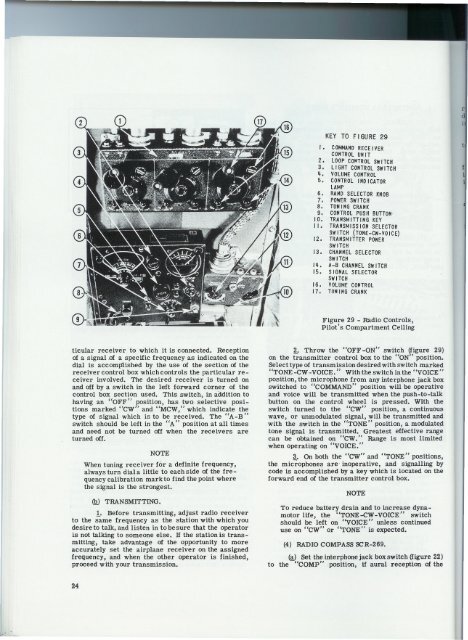
:dKEY TO FIGURE 29I. COMMANDRECEIVERCONTROLUNIT2. LOOPCO"TROLSWITCH3. LIGHT CONTROLSWITCHq. VOLUMECONTROL5. CONTROLINDICATORLAMP6. BANDSELECTORKNOB7. POWERSWITCH8. TUNINGCRANK9. CONTROLPUSHBUTTON'10. TRANSMITTINGKEYI I.TRANSMISSIONSELECTORSWITCH(TONE-CW-VOICE)12. TRANSMITTERPOWERSWITCH13. CHANNELSELECTORSWITCHIq. A-B CHANNELSWITCH15. SIGNALSELECTORSWITCH16. VOLUMECONTROL<strong>17</strong>. TUNINGCRANKtfFigure 29 - Radio Controls,Pilot's Compartment Ceilingticular receiver to which it is connected. Receptionof a signal.of a specific frequency as indicated on thedial is accomplished by the use of the section of thereceiver control box which controls the particular receiverinvolved. The desired receiver is turned onand off by a switch in the left forward corner of thecontrol box section used. This switch, in addition tohaving an "OFF" position, has two selective positionsmarked "cw" and "MCW," which indicate thetype of signal which is to be received. The "A-B"switch should be left in the "A" position at all timesand need not be turned off when the receivers areturned off.NOTEWhen tuning receiver for a definite frequency,always turn dial a little to each side of the frequencycalibration mark to find the point wherethe signal is the strongest. .(Q) TRANSMITTING.1. Before transmitting, adjust radio receiverto the same frequency as the station with which youdesire to talk, and listen in to be sure that the operatoris not talking to someone else. If the station is transmitting,take advantage of the opportunity to moreaccurately set the airplane receiver on the assignedfrequency, and when the other operator is finished,proceed with your transmission.!. Throw the "OFF-ON" switch ~figtire 29)on the transmitter control box to the "ON' position.Select type of transmission desired with switch marked"TONE -CW -VOICE." With the switch in the "VOICE"position, the microphone from any interphone jack boxswitched to "COMMAND" position. will be operativeand voice will be transmitted when the push-to-talkbutton on the control wheel is pressed. With theswitch turned to the "cw" position, a continuouswave, or unmodulated signal, will be transmitted andwith the switch in the "TONE" position, a modulatedtone signal is transmitted. Greatest effective rangecan be obtained on "CW." Range is most limitedwhen operating on "VOICE."3. On both the "cw" and "TONE" positions,the microphones are' inoperative, and signalling bycode is accomplished by a key which is located on theforward end of the transmitter control box.NOTETo reduce battery drain and to increase dynamotorlife, the "TONE-CW-VOICE" switchshould be left on "VOICE" unless continueduse on "cw" or "TONE" is expected.(4) RADIO COMPASS SCR-269.@) Set the interphone jack box switch (figure 22)to the "COMP" position, if aural reception of the24