HEAVY DUTY FLAP GATES SPEC SHEET: - Armtec
HEAVY DUTY FLAP GATES SPEC SHEET: - Armtec
HEAVY DUTY FLAP GATES SPEC SHEET: - Armtec

Create successful ePaper yourself
Turn your PDF publications into a flip-book with our unique Google optimized e-Paper software.
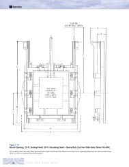
<strong>HEAVY</strong> <strong>DUTY</strong> <strong>FLAP</strong> <strong>GATES</strong> <strong>SPEC</strong> <strong>SHEET</strong>:GeneralFlap gates and accessories shall be of the size, material and construction shown on the drawings andspecified herein. They shall by Hydro Gate heavy-duty flap gates or approved equal, with circular, square orrectangular openings. Similar installations shall have operated successfully for five years or more. Allcomponent parts shall be of the type material shown in the “Materials” section of this specification. TheMaterial Combination Number applicable to each gate shall be shown in the “Gate Schedule.”SeatThe seat shall be flat back and shall be cast in one piece with a raised section around the perimeter of thewaterway opening to mount the seating faces. The raised section shall provide a seating plane diverging topto bottom from the plane of the mounting flange to assist in positive closure of the cover. The seat shall beshaped to provide two bosses extended above the top of the waterway opening for mounting the pivot lugs.Pivot lug bosses shall be drilled and tapped for mounting studs. The back of the seat shall be machined to aplane and drilled to mate the anchor or stud layout. Gates attached to concrete shall be mounted on anchorbolts and grouted in place.CoverThe cover shall be cast in one piece with necessary reinforcing ribs, a lifting eye for manual operation, andwith bosses to provide a pivot point connection with the links. Bosses shall be designed to place the hingepins in double shear when the gate is assembled.Seating FacesA full-width, dovetail slot shall be machined around the perimeter of the cover and the seat. Corrosionresistantdovetail seating faces shall be mounted in the slot and held securely without use of screws or otherfasteners. The seating faces shall be machined to a plane with a minimum 63 micro-inch finish.Flap gates subjected to mild slamming action shall have a rubber seating face on the seat. Rubber seatingfaces shall be mounted in a dovetail slot and held securely without use of pins or screws. The seating faceon the cover shall be as specified in the previous section.Pivot LugsEach pivot lug shall be cast in one piece. Lugs shall have double bosses to place the top hinge pins in doubleshear when they are assembled through the link. The lugs shall be adjustable in the horizontal plane withoutremoval of the cover from the gate links. The adjustment shall allow the top pivot point to be moved towardthe gate seat for reduced sensitivity of the cover, or moved away from the gate seat to provide opening withminimum differential head. Two corrosion-resistant studs shall be used to connect each pivot lug to the gateseat.LinksThe links connecting the cover and pivot lugs shall be heavy duty and cast in one piece. Each link shall beprovided with commercial grade, corrosion-resistant bushings at each pivot point. The bottom of the linksshall be provided with an adjusting screw to properly align seating faces on the cover with respect to theseat. The links shall be designed to limit the double hinge action, preventing the cover from rotatingsufficiently to become wedged in the open position.FastenersAll anchor bolts, assembly bolts, screws, studs and nuts shall be of ample size to safely withstand the forcescreated by operation of the gate under the heads shown in the “Gate Schedule”. Quantity and size of thefasteners shall be of recommended by the manufacturer. Anchor bolts shall be furnished with two nuts eachto facilitate installation and alignment of the gates when attached to concrete.
PaintingMachined surfaces shall be coated with a water-resistant, rust-preventive compound. All cast iron parts shallbe shop cleaned and painted in accordance with the manufacturer’s standard practice.Drawings for ApprovalDrawings showing the dimensions and details required to locate and install the component assemblies shallbe submitted for the engineer’s approval prior to fabrication.InstallationInstallation of all parts shall be done by the contractor in a workmanlike manner and in accordance with themanufacturer’s instructions. It shall be the contractor’s responsibility to handle, store and install the gate instrict accord with the manufacturer’s drawings and recommendations.MaterialsThe “Material Combination Number” included in the “Gate Schedule” and shown below defines the type ofmaterial for the component parts of the gates and accessories included in this specification. Materials shallconform to the requirements of the following ASTM standards. When more than one alloy, type or grade ofmaterial is shown, the exact alloy furnished must be at the manufacturer’s option.Cast IronASTM A126, Class BAustenitic Gray Iron Casting(Ni-Resist) ASTM A436, Type 2Stainless Steel (Faces & Anchors)ASTM A276, Type 302 or 304Stainless Steel (Fasteners)ASTM F593 (Bolts), Alloy Group 1Monel (Seating Faces and Fasteners)ASTM B164, Class A or BNaval Bronze (Seating Faces)ASTM B21, Alloy 482Silicon Bronze (Seating Faces)ASTM B98, Alloy 651Rubber (Seating Faces)ASTM D2000, Grade 1BE625Bronze (Bushings)ASTM B584, Alloy 932Stainless Steel (Bushings and Pins)ASTM A582, Type 303