missouri risk-based corrective action (mrbca) process for petroleum ...
missouri risk-based corrective action (mrbca) process for petroleum ...
missouri risk-based corrective action (mrbca) process for petroleum ...

You also want an ePaper? Increase the reach of your titles
YUMPU automatically turns print PDFs into web optimized ePapers that Google loves.
Missouri Department of Natural ResourcesMISSOURI RISK-BASED CORRECTIVEACTION (MRBCA) PROCESS FORPETROLEUM STORAGE TANKSJanuary 2004
ACKNOWLEDGEMENTSThe Missouri Department of Natural Resources acknowledges the help provided by thestakeholders of the Groundwater Remediation Rule in the development of this <strong>process</strong>.These stakeholders, too many to individually list here, participated in numerous meetings,small subgroups, and conference calls. Their untiring ef<strong>for</strong>ts and support of the <strong>process</strong>are highly appreciated.MRBCA Guidance Document iFebruary 24, 2004Final Draft
FOREWORDThis guidance document describes the <strong>risk</strong>-<strong>based</strong> <strong>process</strong> that will be used by the TanksSection of the Missouri Department of Natural Resources (MDNR) to manage <strong>petroleum</strong>releases at <strong>petroleum</strong> storage tank sites. This <strong>process</strong> is consistent with the policies andprocedures discussed by the Groundwater Remediation Rule stakeholders group anddocumented in their June 2003 Process Document.A draft of this guidance document was distributed to a large number of interestedstakeholders in November 2003 <strong>for</strong> comment. The department reviewed all of thecomments submitted and, as appropriate, revised the guidance document accordingly. Asummary of the comments is available at http://www.dnr.mo.gov/alpd/hwp/rbca-04-comments.pdf.This final document is a result of:• Policies agreed upon, and input received from, the stakeholders group,• MDNR’s experience in the management of <strong>petroleum</strong> impacted sites in Missouri,• Assistance provided by MDNR’s outside consultant, and• Review of comments received on the draft document.IMPLEMENTATION OF MISSOURI’S RISK-BASED CORRECTIVE ACTION(MRBCA) PROCESSThe MRBCA Process <strong>for</strong> Petroleum Storage Tanks is available <strong>for</strong> immediate use on any<strong>petroleum</strong> storage tank site. Persons conducting site investigations of newly discoveredreleases are encouraged to use this new guidance.The MRBCA Process <strong>for</strong> Petroleum Storage Tanks replaces the following existingguidance of the Department of Natural Resources: Underground Storage Tank SiteCharacterization Guidance Document, February 1992; the Underground Storage TankCorrective Action Guidance Document, February 1992; and the Underground StorageTank Closure Guidance Document, March 1996.DEPARTMENT WEBSITE FOR IMPLEMENTATION OF MRBCAThis document and supporting <strong>for</strong>ms are available on the web at:http://www.dnr.mo.gov/alpd/hwpDISCLAIMERNOTE: This document represents a final draft of a stakeholder workgroup that isattempting to <strong>for</strong>mulate guidance <strong>for</strong> the implementation of Missouri's <strong>risk</strong>-<strong>based</strong><strong>corrective</strong> <strong>action</strong> program <strong>for</strong> <strong>petroleum</strong> storage tank sites consistent both with themandate of SB 231 and various MDNR communications regarding the implementation of<strong>risk</strong>-<strong>based</strong> <strong>corrective</strong> <strong>action</strong>. While this document has been prepared in a consensusMRBCA Guidance Document iiFebruary 24, 2004Final Draft
workgroup manner, all parties recognize that it is subject to additional revision <strong>based</strong> onexperience. There<strong>for</strong>e, while it is to be used generally as guidance, it is not yet aregulation of the State of Missouri. It is anticipated that this document will continue toevolve <strong>based</strong> on experience. A separate stakeholder group has been <strong>for</strong>med to monitorboth the positive and negative experiences associated with ef<strong>for</strong>ts to implement thisguidance in the context of actual Missouri sites. For further in<strong>for</strong>mation on this GuidanceDocument and its application, contact MDNR.MRBCA Guidance Document iiiFebruary 24, 2004Final Draft
ABBREVIATIONSAPI American Petroleum InstituteAST Aboveground Storage TankASTM American Society <strong>for</strong> Testing and MaterialsAUL Activity Use and LimitationsBTEX Benzene, Toluene, Ethylbenzene, and Xylenes (total)bgs Below Ground Surfacecfs Cubic Feet per SecondCAP Corrective Action PlanCOC Chemicals of ConcernCERCLA Comprehensive Environmental Response, Compensation, and LiabilityActCFR Code of Federal RegulationsCSR Code of State RegulationsDAF Dilution Attenuation FactorDOT Department of TransportationDTL Default Target LevelEDB Ethylene DibromideEDC Ethylene DichlorideEER Environmental Emergency ResponseEM Exposure ModelEPA Environmental Protection AgencyftFeetGSRAD Geological Survey and Resource Assessment DivisionHWP Hazardous Waste ProgramIELCR Individual Excess Lifetime Cancer RiskIRIS Integrated Risk In<strong>for</strong>mation SystemLNAPL Light Non-Aqueous Phase LiquidLEL Lower Explosive LimitMCL Maximum Contaminant LevelMDNRMissouri Department of Natural ResourcesMEGA Missouri Environmental Geology AtlasMLWL Mean Low Water LevelMNA Monitored Natural AttenuationMRBCA Missouri’s Risk-Based Corrective ActionMSDS Material Safety Data SheetMTBE Methyl tert-Butyl EtherNAPL Non-Aqueous Phase LiquidNELAP National Environmental Laboratory Accreditation ProgramNFA No Further ActionOAC Outreach and Assistance CenterOVM Organic Vapor MonitorPAH Polynuclear Aromatic HydrocarbonsPID Photoionization DetectorMRBCA Guidance Document ivFebruary 24, 2004Final Draft
PNAPODPOEPOTWPSTIFQA/QCRBCARBTLRCRARMRMPRRLRSMoSCMSSTLsSWMPTCTDSTPH-DROTPH-GROTPH-OROTSPUELUSDAUSGSUSTVOAVOCWPPPoly Nuclear AromaticsPoint of DemonstrationPoint of ExposurePublicly Owned Treatment WorksPetroleum Storage Tank Insurance FundQuality Assurance/Quality ControlRisk-Based Corrective ActionRisk-Based Target LevelResource Conservation and Recovery ActRisk ManagementRisk Management PlanRequired Reporting LimitRevised Statues of the State of MissouriSite Conceptual ModelSite-Specific Target LevelsSolid Waste Management ProgramToxicity CharacteristicTotal Dissolved SolidTotal Petroleum Hydrocarbon-Diesel Range OrganicTotal Petroleum Hydrocarbon-Gasoline Range OrganicTotal Petroleum Hydrocarbon-Oil Range OrganicTrisodium Phosphate DodecahydrateUpper Explosive LimitUnited States Department of AgricultureUnited States Geological SurveyUnderground Storage TankVolatile Organic AnalysisVolatile Organic CompoundsWater Protection ProgramMRBCA Guidance Document vFebruary 24, 2004Final Draft
TABLE OF CONTENTSCOVER PAGEACKNOWLEDGEMENTSFOREWARDABBREVIATIONSPageiiiiv1.0 INTRODUCTION AND BACKGROUND 1-11.1 INTRODUCTION 1-11.2 APPLICABILITY AND PURPOSE 1-11.3 SPILL REPORTING 1-22.0 OVERVIEW OF MRBCA PROCESS 2-12.1 INTRODUCTION 2-12.2 RISK-BASED CORRECTIVE ACTION PROCESS 2-12.2.1 Site Discovery 2-12.2.2 Comparison with Default Target Levels 2-22.2.3 Development and Validation of Site Conceptual Model 2-22.2.4 Tier 1 Risk Assessment 2-32.2.5 Tier 2 Risk Assessment 2-42.2.6 Tier 3 Risk Assessment 2-42.2.7 Development and Implementation of Risk Management Plan 2-52.2.8 No Further Action under the MRBCA Program 2-52.3 RISK-BASED TARGET LEVELS WITHIN THE MRBCA PROCESS 2-52.4 ANTICIPATED IMPACT ON SITE COSTS 2-62.5 DOCUMENTATION OF THE MRBCA PROCESS 2-73.0 SITE DISCOVERY AND INITIAL RESPONSE 3-13.1 INTRODUCTION 3-13.2 INVESTIGATION OF IMMINENT THREAT 3-13.3 INVESTIGATION OF SUSPECTED RELEASE 3-23.4 INVESTIGATION OF CONFIRMED RELEASE 3-33.5 REPORTING AND CLEAN-UP OF SPILLS AND OVERFILLS 3-33.6 INITIAL SITE CHARACTERIZATION 3-33.7 REMOVAL OF LIGHT NON-AQUEOUS PHASE LIQUID (LNAPL) 3-33.8 COLLECTION AND EVALUATION OF DATA 3-43.9 NO FURTHER ACTION BASED ON DEFAULT TARGET LEVELS 3-44.0 UST CLOSURE GUIDANCE 4-14.1 INTRODUCTION 4-14.2 SUBMISSION OF UST CLOSURE NOTICE 4-1MRBCA Guidance Document viFebruary 24, 2004Final Draft
4.3 CLOSURE OF TANKS BY EXCAVATION OR CLOSURE INPLACE 4-24.4 SOIL SAMPLING DURING UST CLOSURES 4-24.4.1 Collection of Soil Samples 4-24.4.2 Number and Location of Soil Samples 4-34.4.2.1 Soil Sampling <strong>for</strong> UST Removals with No PhysicalEncumbrances 4-34.4.2.2 Soil Sampling Requirements if Groundwater isEncountered During UST Removal 4-34.4.2.3 Soil Sampling Requirements <strong>for</strong> USTs Resting onConcrete 4-44.4.2.4 Sampling Requirements When Bedrock is Found in theExcavation 4-44.4.2.5 Soil Sampling Requirements <strong>for</strong> In-place UST Closure4-64.4.2.6 Additional Soil Sampling Requirements <strong>for</strong> All USTClosures 4-64.4.3 Groundwater Sampling Requirements <strong>for</strong> UST Closures 4-84.4.3.1 Sampling of Groundwater Encountered During USTExcavation and Removal 4-94.4.3.2 Groundwater Sampling if Encountered During in-PlaceClosure 4-94.4.3.3 Groundwater Sampling if Not Encountered During USTExcavation and Removal 4-94.4.4 Sampling Sites after Excavation of Contamination 4-104.4.4.1 Excavation Walls 4-104.4.4.2 Excavation Floor 4-114.4.4.3 Sampling near Potential Pathways 4-114.4.4.4 Groundwater Sampling 4-114.4.4.5 Location of Wells 4-114.5 WASTE DISPOSAL AND TREATMENT 4-114.5.1 On-site Storage of Excavated Soil 4-124.5.2 Recovered Product 4-124.5.3 Disposal of Petroleum Contaminated Pit Water 4-134.5.3.1 Disposal at a Municipal Wastewater TreatmentFacility 4-134.5.3.2 Discharge Under a General Permit 4-144.5.3.3 Disposal at a Waste Disposal Facility 4-144.5.4 Disposal of UST Wastes 4-144.5.5 UST Disposal/Recycling 4-154.5.6 Recording of USTs Closed In-Place 4-154.5.7 Disposal of Petroleum Contaminated Soil 4-164.5.8 Treatment of Petroleum Contaminated Soil 4-164.5.9 Reusing Excavated Soil as Fill 4-164.5.10 Applicability of the Toxicity Characteristic Rule 4-174.6 SUBMISSION OF THE CLOSURE REPORT 4-17MRBCA Guidance Document viiFebruary 24, 2004Final Draft
5.0 SITE CHARACTERIZATION AND OTHER DATA REQUIREMENTSFOR MRBCA PROCESS 5-15.1 INTRODUCTION 5-15.2 CHRONOLOGY OF SITE EVENTS 5-25.3 NATURE, MAGNITUDE, AND LOCATION OF RELEASE 5-25.3.1 Location and Date of Release 5-35.3.2 Quantity of Release 5-35.3.3 Product Released and Chemicals of Concern 5-35.3.4 Interim Corrective Actions 5-55.4 SITE INFORMATION 5-55.4.1 Site and Site Area Maps 5-55.4.2 Ground Surface Conditions 5-65.4.3 Location of Utilities On and Adjacent to the Site 5-65.4.4 On-site Groundwater Use 5-75.4.5 Regional Hydrogeology and Aquifer Characteristics 5-75.5 ON-SITE AND OFF-SITE LAND USE AND RECEPTORINFORMATION 5-85.5.1 Current Land Use 5-85.5.2 Future Land Use 5-95.5.3 Leased Property and Existing Restrictions 5-95.5.4 Water Well Survey 5-95.5.5 Ecological Receptor Survey 5-105.6 VADOSE ZONE SOIL CHARACTERISTICS 5-105.6.1 Thickness of Vadose Zone and Depth to Groundwater 5-115.6.2 Dry Bulk Density (g/cc) 5-115.6.3 Porosity (cc/cc-soil) 5-125.6.4 Volumetric Water Content/Moisture Content (cc/cc) 5-125.6.5 Fr<strong>action</strong>al Organic Carbon Content in Soil (g-C/g-soil) 5-135.7 SATURATED ZONE CHARACTERISTICS 5-145.7.1 Hydraulic Conductivity (cm/sec) 5-145.7.2 Hydraulic Gradient (cm/cm) 5-145.7.3 Thickness of Capillary Fringe (cm) 5-155.7.4 Saturated Zone Soil Characteristics 5-155.7.5 Occurrence and Rate of Biodegradation 5-155.8 DISTRIBUTION OF COCs IN SOIL 5-165.8.1 Delineation Criteria, Area of Release, and Point of Release 5-175.8.2 Determining Area of Release 5-185.9 DISTRIBUTION OF COCs IN GROUNDWATER 5-215.9.1 Delineation of Groundwater Contamination 5-215.9.2 Groundwater Sampling 5-215.9.3 Determination of Plume Stability 5-235.10 SURFACE WATER AND SEDIMENT SAMPLING 5-235.11 SOIL VAPOR SAMPLING 5-245.12 LABORATORY QA/QC 5-24MRBCA Guidance Document viiiFebruary 24, 2004Final Draft
6.0 GENERAL CONSIDERATIONS FOR RISK ASSESSMENT 6-16.1 DEVELOPMENT OF AN EXPOSURE MODEL 6-16.1.1 Land Use 6-26.1.1.1 Determine Current Land Use 6-26.1.1.2 Determine Most Likely Future Land Use 6-26.1.1.3 On-site and Off-site Receptors 6-36.1.2 Receptors 6-36.1.2.1 Human Receptors 6-36.1.2.2 Ecological Receptors 6-46.1.2.3 Utilities 6-46.1.3 Human Exposure Pathways and Routes of Exposure 6-56.1.3.1 Pathways <strong>for</strong> Inhalation 6-56.1.3.2 Pathways <strong>for</strong> Surficial Soils (0-3 feet bgs) 6-66.1.3.3 Pathways <strong>for</strong> Subsurface Soils (>3 feet bgs to the watertable) 6-66.1.3.4 Pathways <strong>for</strong> Groundwater 6-76.1.3.5 Pathways <strong>for</strong> Surface Water and Sediments 6-76.1.3.6 Other Pathways 6-76.1.4 Exposure Domain 6-76.2 CALCULATION OF RISK-BASED TARGET LEVELS 6-86.2.1 Target Risk Level 6-86.2.2 Quantitative Toxicity Factors 6-96.2.3 Exposure Factors 6-96.2.4 Fate and Transport Parameters 6-96.2.5 Physical and Chemical Properties 6-96.2.6 Mathematical Models 6-106.3 EVALUATION OF GROUNDWATER USE 6-116.3.1 Current Conditions 6-116.3.2 Future Conditions 6-126.3.3 Evaluation of Complete Pathway 6-146.4 SURFACE WATER AND STREAM PROTECTION 6-146.4.1 Protection of Streams 6-156.4.2 Protection of Lakes 6-176.5 ESTIMATION OF REPRESENTATIVE CONCENTRATION 6-176.6 ECOLOGICAL RISK EVALUATION 6-186.7 CONSIDERATION OF NUISANCE CONDITIONS 6-196.8 EVALUATION OF LIGHT NON-AQUEOUS PHASE LIQUID(LNAPL) 6-196.8.1 Protection against Explosive Risk 6-206.8.2 LNAPL Plume Shall be Fully Delineated 6-206.8.3 LNAPL Tiered Risk Assessment 6-206.8.4 Plume Stability 6-216.8.5 Practicability of LNAPL Removal 6-216.9 ACTIVITY AND USE LIMITATIONS 6-21MRBCA Guidance Document ixFebruary 24, 2004Final Draft
7.0 TIER 1 RISK ASSESSMENT 7-17.1 STEP 1: COMPILATION OF DATA AND IDENTIFICATION OFDATA GAPS 7-17.2 STEP 2: DEVELOPMENT OF EXPOSURE MODEL 7-27.3 STEP 3: COLLECTION OF DATA TO FILL DATA GAPS 7-27.4 STEP 4: CALCULATION OF EXPOSURE PATHWAY-SPECIFICREPRESENTATIVE CONCENTRATIONS 7-27.5 STEP 5: COMPARISON OF TIER 1 RBTLs WITH SITE-SPECIFICREPRESENTATIVE CONCENTRATIONS 7-37.6 STEP 6: RECOMMENDATIONS FOR THE NEXT COURSE OFACTION 7-47.7 STEP 7: DOCUMENTATION OF TIER 1 RISK ASSESSMENT 7-58.0 TIER 2 RISK ASSESSMENT 8-18.1 STEP 1: COMPILATION OF SITE-SPECIFIC FATE ANDTRANSPORT PARAMETERS 8-18.1.1 Soil Parameters 8-18.1.2 Groundwater Parameters 8-48.2 STEP 2: DEVELOPMENT OF TIER 2 SSTLs 8-68.3 STEP 3: COMPARISON OF TIER 2 SSTLs WITH SITE-SPECIFICREPRESENTATIVE CONCENTRATIONS 8-68.4 STEP 4: RECOMMENDATIONS FOR THE NEXT COURSE OFACTION 8-68.5 STEP 5: DOCUMENTATION OF TIER 2 RISK ASSESSMENT 8-79.0 TIER 3 RISK ASSESSMENT 9-19.1 STEP 1: DEVELOPMENT OF A TIER 3 WORK PLAN 9-19.2 STEP 2: COLLECTION OF ADDITIONAL DATA, IF NECESSARY 9-29.3 STEP 3: DEVELOPMENT OF TIER 3 TARGET LEVELS 9-29.3.1 Forward Mode 9-29.3.2 Backward Mode 9-39.4 STEP 4: COMPARISON OF TIER 3 TARGET LEVELS WITHREPRESENTATIVE CONCENTRATIONS 9-39.5 STEP 5: RECOMMENDATIONS FOR THE NEXT COURSE OFACTION 9-39.6 STEP 6: DOCUMENTATION OF TIER 3 RISK ASSESSMENT 9-410.0 RISK MANAGEMENT PLAN 10-110.1 NEED FOR A RISK MANAGEMENT PLAN 10-110.2 CONTENTS OF RISK MANAGEMENT PLAN 10-110.3 COMPLETION OF RISK MANAGEMENT ACTIVITIES 10-310.4 NO FURTHER ACTION PROCEDURE 10-4MRBCA Guidance Document xFebruary 24, 2004Final Draft
11.0 ACTIVITY AND USE LIMITATION POLICY 11-111.1 APPLICATION OF POLICY 11-111.2 ACTIVITY AND USE LIMITATION POLICY FOR PETROLEUMSTORAGE TANK SITES 11-111.2.1 Introduction 11-111.2.2 Definitions 11-111.2.3 Application of Policy at Operating Tank Facilities 11-311.2.4 Application of Policy at Sites That Are No Longer Operating TankFacilities 11-312.0 REPORTING 12-112.1 TANK CLOSURE 12-112.1.1 Closure Notice 12-112.1.2 Closure Report 12-112.2 SITE DISCOVERY 12-212.2.1 Release/Suspected Release Report 12-212.2.2 Initial Hazard Abatement Measures Report 12-212.2.3 Site Check Report 12-312.2.4 System Test Report 12-412.3 SITE CHARACTERIZATION 12-412.3.1 Work Plans <strong>for</strong> Site Characterization & Monitoring 12-412.3.2 Periodic Monitoring Reports 12-512.3.3 Site Characterization Report 12-712.3.4 Soil Vapor Measurement Work Plan 12-812.3.5 Soil Vapor Monitoring Report 12-812.4 TIERED RISK ASSESSMENT 12-912.4.1 Tier 1 Risk Assessment Report 12-912.4.2 Tier 2 Risk Assessment Report 12-1012.4.3 Tier 3 Work Plan 12-1212.4.4 Tier 3 Risk Assessment Report 12-1212.5 RISK MANAGEMENT PLAN (RMP) 12-1312.5.1 Risk Management Plan 12-1312.5.2 Interim Corrective Action Work Plan 12-1412.5.3 LNAPL Removal Work Plan 12-1412.5.4 Activity and Use Limitations Work Plan 12-1512.5.5 Corrective Action Plan 12-1612.5.6 RMP Per<strong>for</strong>mance Monitoring Plan 12-1712.6 RMP COMPLETION AND PERFORMANCE MONITORINGREPORT 12-1712.6.1 Interim Corrective Action Report 12-1812.6.2 LNAPL Removal Report 12-1912.6.3 Activity and Use Limitations Report 12-2012.6.4 Corrective Action Report 12-21MRBCA Guidance Document xiFebruary 24, 2004Final Draft
13.0 REFERENCES 13-1MRBCA Guidance Document xiiFebruary 24, 2004Final Draft
LIST OF TABLESTable 2-1 Comparison of Risk Assessment OptionsTable 2-2 Comprehensive List of Reports to be Submitted to MDNRTable 3-1 Default Target LevelsTable 4-1 Soil Concentration Levels to Determine the Need <strong>for</strong> GroundwaterEvaluation During Tank ClosureTable 5-1 Chemicals of Concern <strong>for</strong> Different Product ReleasesTable 5-2 Weight Percents <strong>for</strong> COCs in Different ProductsTable 5-3 Required Reporting LimitsTable 6-1 Allowable COC Concentrations in Surface WaterTable 6-2 Calculation of Representative ConcentrationsTable 6-3 Vapor Concentrations Protective of Explosive HazardsTable 7-1(a) Tier 1 Risk-Based Target Levels <strong>for</strong> Residential Land UseTable 7-1(b) Tier 1 Risk-Based Target Levels <strong>for</strong> Non-residential Land UseTable 7-1(c) Tier 1 Risk-Based Target Levels <strong>for</strong> Construction WorkerTable 7-1(d) Soil Concentration Protective of Groundwater <strong>for</strong> Different Distances toPOE: Distance to Groundwater 50 ftFigure 2-1Figure 2-2Figure 4-1LIST OF FIGURESKey Activities Conducted under the MRBCA ProgramMRBCA Process FlowchartFlowchart to Determine Need <strong>for</strong> Groundwater Investigation During TankClosure ActivitiesFigure 4-1(a) Tank Floor Sampling Where No Physical Encumbrances Exist <strong>for</strong> Tanks1,000 Gallons or LessFigure 4-1(b) Tank Floor Sampling Where No Physical Encumbrances Exist <strong>for</strong> TanksGreater than 1,000 GallonsFigure 4-1(c) Hydraulic Downgradient Wall Sampling, 20 Feet of Wall or LessFigure 4-1(d) Hydraulic Downgradient Wall Sampling, Greater than 20 Feet of WallFigure 4-2(a) Tank Excavation Sampling if Groundwater is Encountered <strong>for</strong> SingleTanks 8,000 Gallons or LessFigure 4-2(b) Tank Excavation Sampling if Groundwater is Encountered <strong>for</strong> SingleTanks Greater Than 8,000 GallonsFigure 4-2(c) Tank Excavation Sampling if Groundwater is Encountered <strong>for</strong> MultipleTanks 8,000 Gallons or LessFigure 4-2(d) Tank Excavation Sampling if Groundwater is Encountered <strong>for</strong> MultipleTanks Greater Than 8,000 GallonsFigure 4-3(a) Tank Excavation Sampling <strong>for</strong> Single Tanks 8,000 Gallons or LessResting on a Concrete PadMRBCA Guidance Document xiiiFebruary 24, 2004Final Draft
Figure 4-3(b) Tank Excavation Sampling <strong>for</strong> a Single Tank Greater Than 8,000 GallonsResting on a Concrete PadFigure 4-3(c) Tank Excavation Sampling <strong>for</strong> Multiple Tanks 8,000 Gallons or LessResting on a Concrete PadFigure 4-3(d) Tank Excavation Sampling <strong>for</strong> Multiple Tanks Greater Than 8,000Gallons Resting on a Concrete PadFigure 4-4(a) Sampling <strong>for</strong> a Single Tank 8,000 Gallons or Less Resting on BedrockFigure 4-4(b) Sampling <strong>for</strong> a Single Tank Greater Than 8,000 Gallons Resting onBedrockFigure 4-4(c) Sampling <strong>for</strong> Multiple Tanks 8,000 Gallons or Less Resting on BedrockFigure 4-4(d) Sampling <strong>for</strong> Multiple Tanks Greater Than 8,000 Gallons Resting onBedrockFigure 4-5(a) In-Place Closure of a Single Tank 8,000 Gallons or LessFigure 4-5(b) In-Place Closure of a Single Tank Greater Than 8,000 GallonsFigure 4-5(c) In-Place Closure of Multiple Tanks 8,000 Gallons or LessFigure 4-5(d) In-Place Closure of Multiple Tanks Greater Than 8,000 GallonsFigure 4-6(a) Wall Sampling After Excavation of ContaminationFigure 4-6(b) Floor Sampling After Excavation of ContaminationFigure 5-1 Chemical of Concern Selection and AnalysisFigure 5-2 An Example of a Land Use MapFigure 5-3(a) Blank Form of Soil Boring LogFigure 5-3(b) Sample Form of Soil Boring LogFigure 5-4(a) Blank Form of Monitoring Well Installation DiagramFigure 5-4(b) Sample Form of Monitoring Well Installation DiagramFigure 6-1 Flowchart <strong>for</strong> Indoor InhalationFigure 6-2 Site Conceptual Model <strong>for</strong> Domestic Consumption of GroundwaterExposure Pathway AnalysisFigure 6-3 Determination of Groundwater Target Concentration at POEFigure 6-4 Schematic of Leachate Migration from Soil to a StreamFigure 6-5 Procedure <strong>for</strong> Protection of Stream BodyFigure 8-1 Schematic Description of Domenico’s ModelLIST OF APPENDICESAppendix AAppendix BAppendix CAppendix DAppendix EAppendix FAppendix GThis Appendix has been Intentionally Left BlankDevelopment of Risk-Based Target LevelsEvaluation of Indoor Inhalation PathwayA Method <strong>for</strong> Determining if a Water Bearing Unit Should be Consideredan AquiferEstimation of Representative Soil and Groundwater ConcentrationsConsideration of Total Petroleum Hydrocarbons within the MRBCAProcessMRBCA Report FormsMRBCA Guidance Document xivFebruary 24, 2004Final Draft
LIST OF ATTACHMENTSAttachment A Ecological Risk Assessment Tier 1 Screening Checklist <strong>for</strong> PotentialReceptors and Habitat Checklist #1Attachment B Ecological Risk Assessment Tier 1 Screening Checklist <strong>for</strong> PotentialReceptors and Habitat Checklist #2(These attachments are found at the end of Chapter 5.0)MRBCA Guidance Document xvFebruary 24, 2004Final Draft
IMPORTANT CONTACT INFORMATIONAmerican Petroleum Institute (API) (202) 682-8000MDNR (800) 334-6946Air Pollution Control Program (573) 751-4817Regional Offices:Kansas City Regional Office (816) 622-7000Northeast Regional Office (660) 385-2129Southeast Regional Office (573) 840-9750Southwest Regional Office (417) 891-4300St. Louis Regional Office (314) 416-2960Geological Survey and Resource Assessment Division (573) 368-2100Wellhead Protection Section (573) 368-2165Environmental Services Program (573) 526-3315Environmental Emergency Response Unit (573) 634-2436Hazardous Waste Program (573) 751-3176Tanks Section (573) 751-6822Tanks Section (fax) (573) 526-8922Brownfields/Voluntary Cleanup Program (573) 526-8913Technical Assistance Program (800) 361-4827Solid Waste Management Program (573) 751-5401Water Protection Program (573) 751-1300Permits Section (573) 751-6825Missouri Department of Transportation (888) 275-6636Missouri One Call System (800) 344-7483OSHA Technical Data Center (202) 219-7500Petroleum Equipment Institute (PEI) (918) 494-9696Petroleum Storage Tank Insurance Fund (PSTIF) (800) 765-2765RCRA Hotline (800) 424-9346MRBCA Guidance Document xviFebruary 24, 2004Final Draft
USEFUL INTERNET WEB SITESAmerican Petroleum Institute (API)Missouri Department of Natural Resources (MDNR)Missouri Department of Transportation (MoDot)Missouri One Call SystemOSHA Technical Data CenterPetroleum Equipment Institute (PEI)Petroleum Storage Tank Insurance Fund (PSTIF)RCRA Hotlinewww.api.orgwww.dnr.state.mo.us/homednrwww.modot.state.mo.uswww.mo1call.orgwww.osha.govwww.pei.orgwww.pstif.orgwww.epa.gov/epaoswer/hotlineMRBCA Guidance Document xviiFebruary 24, 2004Final Draft
MRBCA Guidance Document xviiiFebruary 24, 2004Final Draft
1.0INTRODUCTION AND BACKGROUND1.1 INTRODUCTIONThe Tanks Section of the Missouri Department of Natural Resources’ (MDNR) HazardousWaste Program is charged with the task of overseeing response <strong>action</strong>s at regulated<strong>petroleum</strong> storage tank sites (both underground and aboveground) having <strong>petroleum</strong>hydrocarbon contamination. The primary objective and responsibility of the Tanks Sectionis to protect human health and the environment. Because the science and state of practicerelated to the investigation and remediation of contamination at tank sites has advanced inrecent years, MDNR, with the help of a stakeholder group1, undertook an ef<strong>for</strong>t to reviewand revise the <strong>process</strong> by which tank sites are investigated and remediated. That ef<strong>for</strong>t led tothe development of a <strong>process</strong> that focuses on the actual and potential <strong>risk</strong>s <strong>petroleum</strong>contamination poses to human health and the environment. The Tanks Section’s ef<strong>for</strong>ts areconsistent with, and a part of, MDNR’s agency-wide ef<strong>for</strong>t to establish a consistent <strong>risk</strong><strong>based</strong>approach <strong>for</strong> the management of contaminated sites in Missouri.The approach presented in this guidance document is intended to result in a more consistentand predictable regulatory <strong>process</strong> <strong>for</strong> property owners and developers who are managingissues related to releases from <strong>petroleum</strong> storage tanks. In addition, the approach presentedherein will likely result in a reduction in the overall cost of remediating <strong>petroleum</strong> storagetank sites while maintaining acceptable <strong>risk</strong> levels. Although MDNR will not allow costconsiderations to compromise public health or the environment, it recognizes the need topromote cost-effective site activities (characterization as well as remediation) that areprotective of human health and the environment.This integrated <strong>risk</strong>-<strong>based</strong> decision-making framework <strong>for</strong> the investigation and remediationof <strong>petroleum</strong> impacted sites is subsequently referred to as the Missouri Risk-BasedCorrective Action (MRBCA) <strong>process</strong>. This customized <strong>process</strong> builds on the genericframework developed by the American Society <strong>for</strong> Testing and Materials (ASTM) in theirstandard E1739-95.1.2 APPLICABILITY AND PURPOSEThe MRBCA <strong>process</strong> is applicable to all media and all regulated <strong>petroleum</strong> storage tank sites(both aboveground and underground). Neither the entity responsible <strong>for</strong> the tanks nor theMDNR have the choice of picking or choosing the media or sites to which this <strong>process</strong> willapply, except during the transition period when sites that are close to receiving a “No FurtherAction” (NFA) letter from MDNR will be managed under MDNR’s existing guidance.MDNR will not require that sites previously granted a NFA letter be reevaluated under theMRBCA <strong>process</strong> unless new in<strong>for</strong>mation related to previously addressed or newhydrocarbon releases at the site becomes available.1 Refer to the June 2003 MDNR Preliminary Draft Process Document <strong>for</strong> a list of group members.MRBCA Guidance Document Page 1-1February 24, 2004Final Draft
This document does not in any way replace or supercede MDNR’s en<strong>for</strong>cement orpermitting authority, notification requirements, or other applicable requirements, nor does itreduce any of the responsible party’s obligations under state or federal laws or regulations.The intent of the MRBCA <strong>process</strong> <strong>for</strong> tank sites is to ensure sites are adequatelycharacterized and to provide a means by which site-specific target levels can be developed.These levels are protective of human health and the environment under current andreasonably anticipated future conditions. This document provides a technically defensibleprocedure <strong>for</strong> developing site-specific <strong>risk</strong>-<strong>based</strong> target levels and investigating releases at<strong>petroleum</strong> storage tank sites.This document has been developed <strong>for</strong> environmental professionals having experience in,and a working knowledge of, site assessment and investigation, <strong>risk</strong> assessment, andremedial <strong>action</strong>s. Technical in<strong>for</strong>mation is included that describes the MRBCA <strong>process</strong> andits elements, including site assessment, <strong>risk</strong> assessment, <strong>risk</strong> management, and the tankclosure <strong>process</strong> as developed by MDNR. Since the development of <strong>risk</strong>-<strong>based</strong> target levelsis an integral part of the overall <strong>process</strong> of <strong>risk</strong> management and has not been describedearlier in Missouri’s guidance documents, the calculation of <strong>risk</strong>-<strong>based</strong> target levels isdescribed at length in this manual. However, this manual is not intended to be a generalguide to every aspect of the practice of <strong>risk</strong> assessment. Prior experience or training isnecessary <strong>for</strong> an individual to correctly implement the MRBCA <strong>process</strong> and, by that, ensureefficient site management.Note that this guidance document replaces the following MDNR documents pertaining to<strong>petroleum</strong> storage tanks and tank sites:• March 1996. Underground Storage Tank Closure Guidance Document,• February 1992. Underground Storage Tank Site Characterization GuidanceDocument, and• February 1992. Petroleum Storage Tank Corrective Action Guidance Document.1.3 SPILL REPORTINGReport <strong>petroleum</strong> releases at the earliest practical moment to MDNR at (573) 634-2436.The purpose and intent of this guidance is to provide a <strong>process</strong> <strong>for</strong> addressing <strong>petroleum</strong>releases in a manner that is protective of human health and the environment. This guidancedoes not relieve persons from the requirements of Section 260.500 to 260.550 RSMo,commonly referred to as the "Spill Bill," or the regulations promulgated thereunder. For anygiven site, various measures may be required by MDNR to address a hazardous substanceemergency. At a minimum, all releases of <strong>petroleum</strong> greater than 50 gallons (25 gallons <strong>for</strong>underground storage tank (UST) sites) shall be reported at the earliest practical moment toMDNR at (573) 634-2436.2.0MRBCA Guidance Document Page 1-2February 24, 2004Final Draft
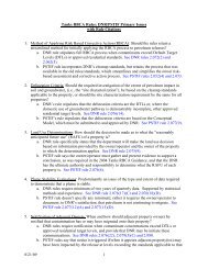
OVERVIEW OF MRBCA PROCESS2.1 INTRODUCTIONThis section presents an overview of the MRBCA <strong>process</strong> as it applies to <strong>petroleum</strong>underground and above ground storage tanks (UST/ASTs). The MRBCA <strong>process</strong> beginswhen a <strong>petroleum</strong> release is suspected or discovered and includes all subsequent activities(except those conducted under 260.500 through 260.550 RSMo and the regulationspromulgated thereunder, as discussed at Section 1.3 of this document) until MDNR issues a“No Further Action” (NFA) letter <strong>for</strong> the release. Subsequent to site discovery and thecontrol of any imminent hazards, the MRBCA <strong>process</strong> requires the following types ofactivities:• Site Characterization and delineation of impacts in soil, groundwater, surface water,sediments and soil vapor, as applicable. The activities culminate in the developmentof a site conceptual model, which includes an exposure model;• Risk assessment activities at the Tier 1, Tier 2, and Tier 3 level, as applicable. AtTiers 1 and 2, these activities culminate in the development of clean-up levels and, atall tiers, a determination of the nature and extent of necessary <strong>risk</strong> managementactivities; and• Risk management activities that ensure human health and the environment areadequately protected from site-specific impacts under both current and reasonablyanticipated future activities on and near the site.Figure 2-1 illustrates the activities discussed above. Although these activities arefundamentally technical and rely on a variety of different scientific disciplines (geology,hydrology, engineering, chemistry, toxicology, land use planning, etc), they also entailmaking assumptions and policy choices that must be consistent with the policies andregulations established by MDNR. These policy choices and the specific steps of theMRBCA <strong>process</strong> are described in this section. Subsequent sections of this documentdescribe the details of each step.2.2 RISK-BASED CORRECTIVE ACTION PROCESSThe overall RBCA <strong>process</strong> <strong>for</strong> a site where a release of <strong>petroleum</strong> from an UST/ASTsystem(s) is suspected or confirmed is illustrated in the flowchart at Figure 2-2 and isdiscussed below.2.2.1 Site DiscoveryThe MRBCA <strong>process</strong> begins with the discovery of a contaminated or potentiallycontaminated UST/AST site. A site might be discovered and reported to the MDNR under avariety of circumstances including, but not limited to, (i) system closure, (ii) a site checkMRBCA Guidance Document Page 2-2February 24, 2004Final Draft
investigation resulting in confirmation of a release, and (iii) identification of an imminenthazard (e.g., vapors in sewers or buildings, etc.). Sites might also be identified duringinvestigations conducted as a part of real estate trans<strong>action</strong>s, investigations conducted inanticipation of land development, and the occurrence of accidents and spills.The site discovery <strong>process</strong> should generally result in the identification of, and generation ofanalytical data <strong>for</strong>, affected media at a site. This initial data should, ideally, represent thepoint or points of release, the chemicals of concern (COCs), and the maximumconcentrations of the COCs.The <strong>process</strong> of site discovery and reporting is discussed in further detail in Section 3.0 ofthis document.2.2.2 Comparison with Default Target LevelsThis step involves the comparison of maximum site concentrations with the default targetlevels (DTLs – found at Table 3-1 of this document) and occurs after a release has beenconfirmed and affected media have been identified and sampled. If the maximum mediaspecificconcentrations at a site are less than the DTLs, and provided the site poses noobvious <strong>risk</strong> to ecological receptors, MDNR will issue a NFA letter pertaining to the site. Insuch case, an ecological screening assessment as per subsections 5.5.5 and 6.6 of thisguidance will not be required.If the maximum soil or groundwater concentrations exceed the DTLs, the person per<strong>for</strong>mingthe evaluation may either adopt DTLs as the cleanup levels and develop a <strong>risk</strong> managementplan (RMP) to achieve those levels, or per<strong>for</strong>m a tiered <strong>risk</strong> assessment.Since MDNR may issue a NFA letter <strong>for</strong> the release <strong>based</strong> on a comparison ofconcentrations of COCs found on the site with the DTLs, the data available <strong>for</strong> thecomparison must accurately represent the maximum media-specific COC concentrations. ANFA determination at this step means that the concentrations of COCs present at the site donot pose an unacceptable <strong>risk</strong> to human health or the environment, regardless of how the sitemay be used or developed in the future.Note that “maximum concentration” refers to the current maximum concentration of a COC.At sites where remedial activities or additional releases may have occurred since the timesamples were collected, new data will be necessary to represent current conditions.2.2.3 Development and Validation of Site Conceptual ModelIf the relevant maximum concentrations of COCs exceed the DTLs and the DTLs are notselected as the cleanup levels, a site conceptual model (SCM) must be developed andvalidated. A SCM provides the framework <strong>for</strong> the overall management of a site and shouldhelp guide data collection and, subsequently, <strong>risk</strong> management activities at the site. TheSCM is conceptual rather than tangible, though the evaluator might find written notes,diagrams, and flow charts beneficial in developing the SCM. While the SCM will not beMRBCA Guidance Document Page 2-3February 24, 2004Final Draft
submitted to MDNR, the data resulting from SCM validation will be.Key elements of the SCM include (i) release scenario, contaminant source, and COCs, (ii) anexposure model (EM) that focuses on the receptors, pathways and routes of exposure undercurrent and reasonably anticipated future land use conditions, (iii) site stratigraphy andhydrogeology, and (iv) spatial and temporal distribution of COCs. An important part of thisstep is the validation of the SCM through the collection of site-specific data. The validation<strong>process</strong> is similar to the traditional site investigation step in that it may involve, <strong>for</strong> instance,installation and sampling of monitoring wells and collection of soil data both on-site and offsite.Additionally, validation involves the determination of land use and the development ofan EM. At sites that are currently undergoing investigation or <strong>corrective</strong> <strong>action</strong>, this stepmay involve the compilation of relevant historic data, identification of data gaps, and thecollection of missing data so that a tiered <strong>risk</strong> assessment can be completed.Data needs <strong>for</strong> a tiered <strong>risk</strong> assessment are presented in Section 5.0.2.2.4 Tier 1 Risk AssessmentA Tier 1 <strong>risk</strong> assessment requires the (i) selection of relevant Tier 1 <strong>risk</strong>-<strong>based</strong> target levels(RBTLs) from lookup tables developed by MDNR, and (ii) comparison of these levels withrepresentative concentrations (note that, at Tier 1, representative rather than maximumconcentrations are compared to the target levels, except <strong>for</strong> surficial soil in a residentialsetting, <strong>for</strong> which maximum concentrations are used). Tier 1 RBTLs will be selected <strong>for</strong>each COC, each complete pathway, and each media of concern identified in the EM. TheTier 1 RBTLs can be found in Tables 7-1(a) through (f) in Section 7.0 of this document.Based on the comparison of representative concentrations and Tier 1 RBTLs, one of thefollowing three decisions is possible:• Request a NFA letter from MDNR if the representative concentrations (or, <strong>for</strong>surficial soil in a residential setting, maximum concentrations) do not exceed theRBTLs and other conditions <strong>for</strong> issuance of a NFA have been met (e.g., necessaryactivity and use limitations (AULs) in place, no ecological concerns, etc.),• Adopt Tier 1 RBTLs as the cleanup levels and prepare and submit a RMP to achievethese levels, or• Per<strong>for</strong>m a Tier 2 <strong>risk</strong> assessment.The specific decision made must be documented and provided to MDNR. Upon completionof the Tier 1 <strong>risk</strong> assessment, the person who conducted the evaluation or who is responsible<strong>for</strong> the site shall provide their recommendations to MDNR. Note, however, that if a Tier 2evaluation immediately follows the Tier 1 assessment, the evaluator need not submit a reportpertaining solely to the Tier 1 assessment. Rather, the Tier 1 and Tier 2 assessments may becombined into a single report that is submitted at the conclusion of the Tier 2 assessment.MRBCA Guidance Document Page 2-4February 24, 2004Final Draft
Details of Tier 1 <strong>risk</strong> assessment are provided in Section 7.0.2.2.5 Tier 2 Risk AssessmentDepending on site-specific conditions and the availability of data, conducting a Tier 2 <strong>risk</strong>assessment might depend on the collection of additional site-specific data. In preparation <strong>for</strong>a Tier 2 <strong>risk</strong> assessment, the EM should be revised, if necessary, and, as appropriate,additional data collected. This data would be used to develop Tier 2 site-specific targetlevels (SSTLs) in accordance with the provisions of Section 8.0 of this guidance.After the Tier 2 SSTLs have been developed, they will be compared with representativeCOC concentration data from the site. Depending on the comparison, the following threeoptions are possible:• Request a NFA letter from MDNR if the representative concentrations (or, <strong>for</strong>surficial soil in a residential setting, maximum concentrations) do not exceed the Tier2 SSTLs <strong>for</strong> all complete routes of exposure and other conditions <strong>for</strong> issuance of aNFA have been met (e.g., AULs in place, no ecological concerns, etc.),• Adopt Tier 2 SSTLs as cleanup levels and develop a RMP to achieve these levels, or• Develop a work plan to per<strong>for</strong>m a Tier 3 <strong>risk</strong> assessment.Details of Tier 2 <strong>risk</strong> assessment are presented in Section 8.0.2.2.6 Tier 3 Risk AssessmentA Tier 3 <strong>risk</strong> assessment allows considerable flexibility to the person conducting theevaluation. Because of the myriad options available at Tier 3, MDNR requires that a workplan be prepared <strong>for</strong> MDNR’s review and approval prior to a Tier 3 <strong>risk</strong> assessment.Once Tier 3 SSTLs have been developed, they are compared to representative COCconcentrations from the site. This comparison will result in one of the following twooptions:• Request a NFA letter from MDNR if the representative concentrations (or, <strong>for</strong>surficial soil in a residential setting, maximum concentrations) do not exceed the Tier3 SSTLs and other conditions <strong>for</strong> NFA have been met (e.g., AULs in place, noecological concerns, etc.), or• Adopt Tier 3 SSTLs as cleanup levels and develop and implement a RMP.Details of Tier 3 <strong>risk</strong> assessment are presented in Section 9.0.2.2.7 Development and Implementation of Risk Management PlanMRBCA Guidance Document Page 2-5February 24, 2004Final Draft
This step involves the development and implementation of a RMP to achieve the cleanuplevels approved by MDNR. Typically, a RMP will be developed after media-specificcleanup levels have been approved by MDNR. The RMP may include a combination ofactive and passive remedial options and/or AULs and a description of what reports will besubmitted and when. As appropriate, the plan should include (i) the type of technology to beused, (ii) an explanation of AULs being proposed, if any, and justification of their use, (iii)an estimate of the time needed to implement the RMP, (iv) data that will be collected tomonitor the effectiveness of the RMP, (v) the manner in which the data will be evaluated,and (vi) steps that will be taken if the RMP is not effective. During implementation of theRMP, sufficient data must be collected and analyzed to allow <strong>for</strong> an appropriate evaluationof the per<strong>for</strong>mance of the plan so that modifications can be made as appropriate. The RMPshould not be implemented without the approval of MDNR.The data collected during implementation of the RMP should be carefully evaluated and adetermination made whether the RMP is progressing as anticipated. The data and theevaluation shall be submitted to MDNR. If the RMP is not progressing as anticipated and aspredicted in the work plan, a proposal <strong>for</strong> modifying the RMP should be developed andsubmitted to MDNR. Modifications of the RMP shall not be implemented without theconcurrence of MDNR.RMP details are presented in Section 10.0.2.2.8 No Further Action under the MRBCA ProgramThe overall objective of all RMPs is to ensure protection of human health and theenvironment under current and reasonably anticipated future conditions. When MDNR issatisfied that cleanup levels have been met or <strong>risk</strong>s have been otherwise managed, MDNRwill issue a NFA letter <strong>for</strong> the site. MDNR’s issuance of a NFA letter indicates that, <strong>based</strong> onthe MRBCA evaluation submitted and the in<strong>for</strong>mation available to MDNR at the time, nofurther <strong>action</strong> is necessary to protect human health and the environment. However, if in thefuture additional in<strong>for</strong>mation becomes available that indicates that the site posesunacceptable <strong>risk</strong> to human health or the environment, MDNR may rescind their decisionand require further <strong>action</strong> at the site.2.3 RISK-BASED TARGET LEVELS WITHIN THE MRBCA PROCESSUnder the MRBCA <strong>process</strong>, any of the following four RBTLs may be accepted as thecleanup levels:DTLs are the most conservative chemical and medium-specific concentrations that allowunrestricted (residential) use of the property. For each COC and each medium, the DTL isthe lowest of the Tier 1 RBTLs. Since DTLs are the most conservative levels, theirapplication does not require evaluation of site-specific exposure pathways, the developmentof a site conceptual model, any activity and use limitations, or the determination of whethergroundwater is used, or is likely to be used, as a water supply source.MRBCA Guidance Document Page 2-6February 24, 2004Final Draft
Tier 1 RBTLs are generic target levels developed by MDNR using conservative defaultparameters that depend on the receptor, media, pathway, route of exposure, and whetherimpacted or threatened groundwater is used, or is likely to be used, as a water supply source.Use of RBTLs may require AULs.Tier 2 SSTLs are site-specific target levels that are calculated using site-specific data andthe guidelines included in this document. Tier 2 SSTLs differ from Tier 1 RBTLs in that theTier 2 SSTLs are <strong>based</strong> on site-specific fate and transport parameter values whereas the Tier1 RBTLs use default, generic fate and transport parameters. Typically but not always Tier 2SSTLs will be higher than Tier 1 RBTLs. As with the Tier 1 RBTLs, depending on thecircumstances, AULs may be required when SSTLs apply.Tier 3 SSTLs are site-specific target levels that are calculated using data collected at the siteand the guidelines included in this document. Compared with Tier 2 SSTLs, Tier 3 SSTLsmay be <strong>based</strong> on the application of fate and transport models other than those used tocalculate the Tier 1 RBTLs and Tier 2 SSTLs. The application of Tier 3 SSTLs might alsorequire the use of AULs, depending on the specific circumstances.Table 2-1 presents the differences between the different target levels within this framework.2.4 ANTICIPATED IMPACT ON SITE COSTSAs a site moves through this tiered <strong>process</strong>, the following can be anticipated:• Higher tiers will require the collection of additional site-specific data, which willincrease data collection, data analysis, and labor costs. Simultaneously, there will bea reduction in the overall uncertainty about the site.• In general, the calculated Tier 2 SSTLs will be higher than the Tier 1 RBTLs becauselower tier levels are designed to be more conservative than higher tier levels. Thus,the cost of <strong>risk</strong> management activities at higher tiers should generally be lower.• The need <strong>for</strong>, and the extent of, regulatory oversight and review will increase.• The level of uncertainty and conservatism will decrease due to the availability ofmore site-specific data.Despite the above differences, there is one very significant similarity: each tier will result incleanup target levels that provide an acceptable level of protection to human health and theenvironment.2.5 DOCUMENTATION OF THE MRBCA PROCESSTo facilitate and allow decisions to be made that are protective of human health and theenvironment, the MRBCA <strong>process</strong> requires the collection and analysis of a considerableamount of data. The outcome of the MRBCA <strong>process</strong> is of considerable interest to a varietyMRBCA Guidance Document Page 2-7February 24, 2004Final Draft
of stakeholders, including but not limited to, MDNR, land owners, developers, lendingagencies, and cities and municipalities. There<strong>for</strong>e, the <strong>process</strong> by which data is collectedand analyzed and important decisions potentially affecting human health and theenvironment are made must be as transparent as possible via adequate and clearcommunication between the person responsible <strong>for</strong> a site and the MDNR. Suchcommunication must occur throughout the MRBCA <strong>process</strong>, from site discovery to issuanceof a NFA letter, so that interested parties can determine if decisions made and activitiesundertaken during the MRBCA <strong>process</strong> at a site were sufficient to adequately protect humanhealth and the environment.The method and <strong>for</strong>mat by which the owner/operator reports data developed under theMRBCA <strong>process</strong> must be consistent (across the state) and unambiguous so that interestedparties can readily understand the:• Nature and extent of the problem at a site,• Sequence of <strong>action</strong>s taken to address the problem,• Data collected to quantify and analyze the problem,• Process used to develop a plan of <strong>action</strong> to address the problem,• Results of the <strong>action</strong>s taken, and• Finally, whether the <strong>action</strong>s taken are adequately protective of human health and theenvironment under current and reasonably anticipated future conditions.To facilitate this type of reporting, Table 2-2 was developed. Table 2-2 presents acomprehensive list of reports that would typically be submitted to MDNR, an approximateschedule <strong>for</strong> submittal of the various reports, and a description of the <strong>for</strong>mat in which thesereports would be submitted. Detailed discussions of these reports are presented in Section12.0 of this document. Section 12.0 identifies:• The specific reports that must be submitted to MDNR,• Data that must be included in each report,• The required reporting <strong>for</strong>mat <strong>for</strong> each report, and• A schedule <strong>for</strong> submission of the reports to MDNR.MRBCA Guidance Document Page 2-8February 24, 2004Final Draft
Site CharacterizationRegulatory Policiesand ProceduresRisk AssessmentRisk ManagementFigure 2-1. Key Activities Conducted under the MRBCA ProgramMRBCA Guidance Document Final Draft February 24, 2004
Closure NoticeSuspected Release10.052Imminent HazardIdentifiedTank Closure andSamplingSystem Test and/orSite CheckReport Results toMDNRHazard AbatementActivities Report IfApplicableConcentration < DTL?YesNoSubmit Closur eReportRelease Confirmed?YesNoStopNoHazardAbatementActivities **Completed?YesSubmit Closur eReportClean up to DTLs?YesBNO FURTHERACTIONDevelopment & Validation of Site Conceptual Model (Include GWConsideration)NoTier 1 EvaluationAFigure 2- 2. MRBCA Proc ess Flowchart (Page 1 of 3)MRBCA Guidance Document Final Draft February 24, 2004
ANoConcentrationsExceed Tier 1Levels?YesCleanup toTier 1 Levels Feasible& Cost-effective?YesNoYesData Available toCalculate Tier 2Levels?NoCollect Relevant DataDevelop Tier 2 LevelsNoConcentrationsExceed Tier 2Levels?YesCleanup toTier 2 Levels Feasibleand Cost-effective?YesDCNoBFigure 2-2. MRBCA Process Flowchart (Page 2 of 3)MRBCA Guidance Document Final Draft February 24, 2004
DCBWork Plan & Data Collection <strong>for</strong> Tier 3Development of Tier 3 LevelsNoSite ConcentrationsExceed Tier 3Levels?Complete AdditionalMonitoringYesDevelopment and Implementation of Risk ManagementPlan (RMP)RMP Completed?NoRe-evaluate and Modify RMP ifnecessaryAdditionalMonitoringRequired?YesYesNoNO FURTHERACTION** Assuming ecological and nuisance conditions if any have been addressed.Figure 2-2. MRBCA Process Flowchart (Page 3 of 3)MRBCA Guidance Document Final DraftFebruary 24, 2004
Table 2-1Comparison of Risk Assessment OptionsFactors DTL Tier 1 Tier 2 Tier 3ExposureFactors 1 Default Default Default Site-specificToxicity Factors 1 Default Default Default Most currentPhysical andChemicalDefault Default Default Most currentProperties 1Fate andTransportParameters 1 Default Default Site-specific Site-specificUnsaturated ZoneAttenuationFate andTransport ModelsComparativeConcentrationsDepth to watertable dependentDepth to watertable dependentDepth to watertable dependentSite-specificmodelDefault Default Default AlternativeMaximumRepresentativeConcentrations-See AppendixERepresentativeConcentrations-See AppendixERepresentativeConcentrations-See AppendixEIELCR 1 x 10 -5 1 x 10 -5 1 x 10 -5 1 x 10 -5Hazard Quotient 1 1 1 1CumulativeEffectsNot considered Not considered Not considered Not consideredGroundwaterIngestionPathwayMCL orequivalentMCL orequivalentMCL orequivalentMCL orequivalentCompleteEcological Risk NA Evaluate Evaluate EvaluateOutcome of NFA, Tier 1, NFA, Tier 2, NFA, Tier 3,EvaluationRMPRMPRMPNFA, RMPLand Use No Yes Yes YesActivity and UseDepend on land use, groundwater use, andNoneLimitationsassumption in <strong>risk</strong> assessmentDTL: Default Target LevelIELCR: Individual Excess Lifetime Cancer RiskMCL: Maximum Contaminant LevelNFA: No Further ActionRMP: Risk Management Plan1 Refer to Appendix BMRBCA Guidance Document February 24, 2004Final Draft
Table 2-2Comprehensive List of Reports to be Submitted to MDNR*REPORT SCHEDULE FORMAT1 Closure Notice As requested by the owner/operator, no less than 30 days prior to closure Forms2 Closure Report Within 60 days of closure Forms3 Release/Suspected Release As soon as practical but no later than 24 hours of discovery Narrative4 Initial Hazard Abatement Measures 20 days from release confirmation Narrative5 Site CheckTo be per<strong>for</strong>med within 7 days from suspected release, report within 60 daysof completion of site checkNarrative and Forms6 System TestsTo be per<strong>for</strong>med within 7 days from suspected release, report within 20 daysof the testNarrative7 Work Plans <strong>for</strong> Site Characterization & Monitoringas requested and agreed to by MDNR or as requested by MDNR (typically 30days of request)Narrative8 Periodic Monitoring Reports As stipulated by MDNR or as requested and agreed to by MDNR Narrative and Forms9 Site Characterization Report(s) As per the schedule in the work plan or stipulated by MDNR Narrative and Forms10 Soil Vapor Measurement Work Plan and Reports As per the schedule in the work plan or stipulated by MDNR Narrative and Forms11 Tier 1 Risk Assessment Report As stipulated by MDNR Narrative and Forms12 Tire 2 Risk Assessment Report As stipulated by MDNR Narrative and Forms13 Tier 3 Work Plan As stipulated by MDNR or as proposed by evaluator and agreed to by MDNR Narrative14 Tier 3 Risk Assessment Report As per the schedule in the work plan or stipulated by MDNR Narrative and Forms15 Risk Management Plan (RMP) As stipulated by MDNR Narrative16 Interim Corrective Action Work Plan and Report As stipulated by MDNR Narrative and Forms17LNAPL (light non-aqueous phase liquid) RemovalWork Plan and ReportAs stipulated by MDNRNarrative and Forms18 Activity and Use Limitations Work Plan and Report As stipulated by MDNR Narrative19 Corrective Action Plans and Report(s) As stipulated by MDNR Narrative and Forms20 RMP Per<strong>for</strong>mance Monitoring Plans and Report As stipulated by MDNR Narrative and Forms* Reports requiring submission to MDNR dependent on site conditions.MRBCA Guidance DocumentFinal Draft February 24, 2004
3.0SITE DISCOVERY AND INITIAL RESPONSE3.1 INTRODUCTIONThe MRBCA <strong>process</strong> starts with the initial suspicion of release followed by activities thateither confirm or refute the release. If the release is confirmed, the MRBCA <strong>process</strong>continues until MDNR issues a “No Further Action” (NFA) letter <strong>for</strong> the release. Note,however, as previously stated, the MRBCA <strong>process</strong> does not include emergency responseactivities conducted under 260.500 through 260.550 RSMo and the regulations promulgatedthereunder.A number of different events may trigger site-specific activities that may ultimately lead tosite discovery. These include but are not limited to:• Observation of <strong>petroleum</strong> products on or near a site, e.g., in utilities, on or adjacentto surface water bodies, in observation wells, etc.,• Unusual underground storage tank (UST) system operating conditions, e.g., suddenloss of product in tanks, erratic behavior of product dispensing equipment, etc.,• Monitoring results from a leak detection system,• Phase I or phase II investigations associated with real estate trans<strong>action</strong>s,• Accidental release, e.g., during refueling of UST’s by tankers, and• Complaints of odors at or adjacent to a site.In each of the above cases, the owner/operator of the UST system must report in writing toMDNR within 24 hours of suspicion and/or confirmation of release (10 Code of StateRegulations (CSR) 20-10.050 Reporting of Suspected Releases), as directed at 3.2 below.Once a release has been confirmed, a site characterization will be necessary to collectrelevant data to per<strong>for</strong>m a <strong>risk</strong>-<strong>based</strong> evaluation (also refer to Section 5.0). Note, however,that MRBCA data collection activities are secondary to addressing all imminent threats andhazardous conditions posed by a release.3.2 INVESTIGATION OF IMMINENT THREATIn all of the above cases the first step upon suspicion and/or confirmation of a release is toreport the release to MDNR at the earliest practical moment.The following points briefly summarize the requirements of Sections 260.500 through260.550, Revised Statues of Missouri (RSMo). Note that MDNR’s Environmental ServicesProgram (ESP) administers the referenced requirements.• Any release of <strong>petroleum</strong> in excess of 50 gallons (25 gallons <strong>for</strong> USTs), constitutes ahazardous substance emergency,• Releases shall be reported to the MDNR at (573) 634-2436 at the earliest practicalmoment,MRBCA Guidance Document Page 3-1February 24, 2004Final Draft
• MDNR will evaluate whether an imminent threat exists,• MDNR may require a person having control over a hazardous substance emergencyto clean up the release and take any reasonable <strong>action</strong>s to end the hazardoussubstance emergency,• MDNR may require such persons to take such <strong>action</strong>s as may be reasonably requiredto prevent recurrence of the hazardous substance emergency, and• In the event such persons fail to act, MDNR may take <strong>action</strong> and pursue recovery ofits costs.Upon completion and documentation of the emergency response activities, and if the releaseof <strong>petroleum</strong> hydrocarbon is confirmed, additional data may have to be collected to per<strong>for</strong>ma <strong>risk</strong>-<strong>based</strong> evaluation.In no case will MDNR approve a <strong>risk</strong> assessment or <strong>risk</strong> management plan if a hazardoussubstance emergency exists or is likely to occur, unless such conditions are specificallyaddressed either through interim <strong>corrective</strong> <strong>action</strong>s or through measures contained in thefinal Risk Management Plan (RMP).3.3 INVESTIGATION OF SUSPECTED RELEASEAs indicated in 10 CSR 20-10.052, the owner/operator must immediately investigate andconfirm all suspected releases of regulated substances within 7 days or as directed byMDNR. Investigation may include, but is not necessarily limited to, a system tightness testand a site check.If a system check reveals a leak, the owner/operator must repair the leak or replace relevantcomponents of the system. Upon repair of the leak, a site investigation may be necessary todetermine the extent of contamination resulting from the release and to per<strong>for</strong>m a <strong>risk</strong>-<strong>based</strong>evaluation.If a system check does not reveal any leaks and the suspicion of release was not <strong>based</strong> on anenvironmental condition (i.e., <strong>petroleum</strong> in the environment), no further investigation wouldbe necessary. However, if the suspicion of release is <strong>based</strong> on an environmental condition,the owner/operator must conduct a site check that involves collection of soil and orgroundwater samples (refer to 10 CSR 20-10.052 1(B)) or other measurements to determinewhether a release has occurred. If a release is confirmed, additional data shall be collectedand a <strong>risk</strong>-<strong>based</strong> evaluation per<strong>for</strong>med.In all of the above cases, in addition to the notification discussed at subsection 3.2 above, theowner/operator must report to MDNR, within 7 days of the suspicion of release, theactivities conducted and whether the suspected release has been confirmed.MRBCA Guidance Document Page 3-2February 24, 2004Final Draft
3.4 INVESTIGATION OF CONFIRMED RELEASEWhen a release is confirmed, the owner/operator must take immediate steps to (i) preventany additional release to the environment, and (ii) mitigate any fire, safety or otherimmediate hazards to human health or the environment.Within 20 days after release confirmation, the owner/operator must submit a report toMDNR summarizing the initial abatement steps (10 CSR 20-10.062).3.5 REPORTING AND CLEAN-UP OF SPILLS AND OVERFILLSThe owner/operator must contain and immediately clean up a spill or overfill. If the spillresults in a release of more than 25 gallons of <strong>petroleum</strong> product to the environment (or lessthan 25 gallons if clean-up cannot be accomplished in 24 hours), the spill must be reported toMDNR within 24 hours by calling (573) 634-2436 and The National Response Center at(800) 424-8802. If the spill/overfill has not been cleaned up, additional data shall becollected and a <strong>risk</strong>-<strong>based</strong> evaluation per<strong>for</strong>med.3.6 INITIAL SITE CHARACTERIZATIONAfter all initial emergency and hazard abatement steps have been completed, no imminentthreats exist at the site, and a release is confirmed, the owner/operator must proceed tocollect data necessary to per<strong>for</strong>m a <strong>risk</strong>-<strong>based</strong> evaluation. Specifics of the type and quantityof data required are presented in Section 5.0 of this document.3.7 REMOVAL OF LIGHT NON-AQUEOUS PHASE LIQUID (LNAPL)At sites where investigation reveals the presence of LNAPL, also called free product, in theenvironment (including the tank pit), the entity per<strong>for</strong>ming the investigation shall remove asmuch LNAPL as practicable <strong>based</strong> on current state-of-the-practice as determined andapproved by MDNR. The primary objective of LNAPL removal is to (i) prevent <strong>risk</strong> of fireand explosion, (ii) reduce <strong>risk</strong> to human health and the environment to an acceptable level,and (iii) prevent further expansion of the dissolved and LNAPL plume.MDNR shall evaluate the practicability of LNAPL removal by evaluating the methodscommonly available <strong>for</strong> such removal, removal rates over time using removal methodsappropriate to a particular site given physical site conditions, the geology associated with thesite of LNAPL, the characteristics of the LNAPL and its constituent parts, the extent towhich remaining LNAPL is contributing to the expansion of a dissolved phase contaminantplume in groundwater, and the fate and consequence of the dissolved phase plume. Anevaluation of the practicability of LNAPL removal shall be undertaken only after reasonableattempts have been made to remove the LNAPL from the environment.At any given site being evaluated under the MRBCA <strong>process</strong>, when LNAPL removalactivities mandated by 10 CSR 25-10.064 have reached asymptotic recovery rates or LNAPLremoval is demonstrably impracticable, and data shows that the remaining LNAPL does notMRBCA Guidance Document Page 3-3February 24, 2004Final Draft
pose an unacceptable <strong>risk</strong> to human health or the environment, the groundwater plume isdemonstrably stable or shrinking, and the LNAPL poses no <strong>risk</strong> of explosion, furtherLNAPL removal might not be required.The evaluator must prepare and submit to MDNR a LNAPL removal report within 45 daysof confirmation of a release as per 10 CSR 20-10.064. Refer to Section 6.8 of this document<strong>for</strong> further in<strong>for</strong>mation regarding the evaluation of LNAPL.3.8 COLLECTION AND EVALUATION OF DATAGeologic data collected as a part of a MRBCA evaluation must be collected by or underthe direct supervision of a geologist or qualified professional engineer registered by theState of Missouri, as such data will be used in a manner that affects or has the potential toaffect public health, safety and welfare. Also, the interpretation of geologic data thataffects or has the potential to affect public health, safety and welfare, must also beconducted by or under the supervision of a Missouri-registered geologist or qualifiedprofessional engineer.All work so per<strong>for</strong>med shall be signed and sealed by the registered geologist inresponsible charge or qualified professional engineer. If the work is not properly signedand sealed, the department will not provide final acceptance or approval of such work.3.9 NO FURTHER ACTION BASED ON DEFAULT TARGET LEVELSAt tank sites impacted by <strong>petroleum</strong> product release(s), soil and groundwatercharacterization typically starts at the point or area of release where the concentrations ofCOCs are the highest. Upon collection of this data, the maximum COC concentrations maybe compared with the default target levels (DTLs) (refer to Table 3-1). If the maximum soiland groundwater concentrations do not exceed the DTLs and the site does not pose anobvious threat to ecological receptors, remediation is not warranted and the entityper<strong>for</strong>ming the evaluation may request a NFA without activity and use limitations (AULs).Further, if these conditions are met, an ecological screening assessment as per Section 6.6 ofthis guidance will not be required.MRBCA Guidance Document Page 3-4February 24, 2004Final Draft
Table 3-1Default Target LevelsChemicals of ConcernSoilGroundwater(mg/kg)(mg/L)Benzene 4.24E-02 Inh 5.00E-03 IngToluene 6.97E+00 Inh 1.00E+00 IngEthylbenzene 3.20E+01 Inh 7.00E-01 IngXylenes (mixed) 2.86E+01 Inh 1.00E+01 IngEthylene Dibromide (EDB) 5.31E-04 Gwp 5.00E-05 IngEthylene Dichloride (EDC) 1.30E-02 Gwp 1.56E-03 IngMethyl-tert-butyl-ether(MTBE) 6.21E-01 Gwp 1.46E-01 IngAcenaphthene 7.70E+01 Gwp 7.28E-02 IngAnthracene 1.60E+03 Gwp 3.64E-01 IngBenzo(a)anthracene 1.84E+00 DC 9.21E-04 IngBenzo(a)pyrene 1.90E-01 DC 2.00E-04 IngBenzo(b)fluoranthene 1.84E+00 DC 9.21E-04 IngBenzo(k)fluoranthene 1.84E+01 DC 9.21E-03 IngChrysene 1.83E+02 DC 9.21E-02 IngDibenzo(a,h)anthracene 1.84E-01 DC 9.21E-05 IngFluoranthene 1.19E+03 DC 6.26E-01 IngFluorene 9.99E+01 Gwp 4.86E-02 IngNapthalene 3.93E-01 Gwp 1.31E-03 IngPyrene 7.51E+02 DC 4.69E-01 IngTPH-GRO 2.76E+01 Inh 2.33E+00 IngTPH-DRO 1.04E+03 Inh 2.86E+01 InhTPH-ORO 5.08E+04 DC 3.18E+01 Ing>C6 - C8 (Aliphatics) 1.17E+01 Inh 9.69E-01 Inh>C8 - C10 (Aliphatics) 2.55E+00 Inh 3.43E-02 Inh>C10 - C12 (Aliphatics) 1.27E+01 Inh 2.29E-02 Inh>C12 - C16 (Aliphatics) 5.77E+02 Inh 5.28E-02 Inh>C16 - C35 (Aliphatics) 5.02E+04 DC 3.13E+01 Ing>C8 - C10 (Aromatics) 1.33E+01 Inh 6.36E-02 Ing>C10 - C12 (Aromatics) 2.40E+01 Gwp 6.36E-02 Ing>C12 - C16 (Aromatics) 4.76E+01 Gwp 6.36E-02 Ing>C16 - C21 (Aromatics) 4.08E+02 Gwp 1.73E-01 Ing>C21 - C35 (Aromatics) 6.25E+02 DC 4.69E-01 IngTertiary-amyl-methyl-ether (TAME) 2.14E+00 Gwp 2.31E-01 IngTertiary-butyl- alcohol (TBA) 3.26E-01 Gwp 1.04E-01 IngEthyl-tert-butyl-ether ( ETBE) 4.68E-02 Gwp 5.52E-03 IngDiisopropyl ether ( DIPE) 5.63E-03 Gwp 4.38E-04 IngEthanol 1.54E+00 Gwp 5.80E-01 IngMethanol 4.18E-01 Gwp 1.09E-01 IngArsenic 4.35E+00 DC 1.00E-02 IngBarium 4.50E+03 DC 2.00E+00 IngCadmium 3.23E+01 DC 5.00E-03 IngChromium 3.76E+04 DC 8.64E+00 IngLead 2.60E+02 NA 1.50E-02 NASelenium 1.34E+02 DC 2.88E-02 IngNotes:DC : Direct contact pathwayNA: Not ApplicableGwp: Protection of domestic groundwater use pathwayIng: Ingestion of waterInh: Indoor inhalation pathwayMRBCA Guidance Document - Final Draft February 24, 2004
4.0UST CLOSURE GUIDANCE4.1 INTRODUCTIONThis section presents requirements <strong>for</strong> tank closures that are regulated under Chapter 319RSMo and 10 CSR 20-10.071-074. Closure of an underground storage tank (UST)means that the tank has been removed or filled with an inert solid material and has had alltank openings (e.g., tank tubes, vent pipes, pipelines) permanently sealed or cappedaccording to the requirements of this section. This guidance may also be used to closeabove ground storage tanks (ASTs) that contain <strong>petroleum</strong> products. Owners ofhazardous substance tanks must submit a plan <strong>for</strong> approval prior to conducting closure.Implementation of the guidance presented in this document will fulfill the requirementsof 10 CSR 20-10-071(4). However, the entity per<strong>for</strong>ming tank closure may presentalternative written procedures to MDNR that may be more appropriate <strong>based</strong> on siteconditions. Similarly, procedures presented in this document may not address all <strong>action</strong>sthat MDNR may determine are necessary. MDNR may require additional <strong>action</strong>s toachieve compliance with applicable laws and regulations.The tank closure <strong>process</strong> generally includes the following activities:• Submission of Storage Tank Closure Notice;• Removal of tank(s) and piping or in-place tank closure;• Collection and analysis of soil and groundwater samples;• Disposal of any waste streams (tank, soil, tank contents, and water) generated;and,• Submission of a tank closure report.The closure of tanks is the responsibility of the owner/operator of the tank and allcorrespondence from MDNR shall be addressed to the owner/operator. However, uponwritten request of the owner, MDNR will facilitate the closure <strong>process</strong> by working withthe company hired by the owner/operator to close the tank.4.2 SUBMISSION OF UST CLOSURE NOTICEThe <strong>process</strong> of tank closure begins when an entity submits a “Storage Tank ClosureNotice” to MDNR. This notice must be submitted at least 30 days prior to initiatingclosure activities, unless tank removal is necessary to abate an emergency. In this case,the tank closure notice shall be submitted at the earliest possible time after abatement ofthe emergency. A blank copy of the <strong>for</strong>m can be found at Appendix G of this documentand can be downloaded from http://www.dnr.state.mo.us/oac/<strong>for</strong>ms/780-1782.pdf.MDNR will review the tank closure notice and return a signed copy to the owner toacknowledge receipt.MRBCA Guidance Document Page 4-1February 24, 2004Final Draft
4.3 CLOSURE OF TANKS BY EXCAVATION OR CLOSURE IN PLACETanks may be closed either by excavation and removal or closed in-place, the latter byfilling the tank(s) with an inert material. In either case, MDNR requires that storagetanks be cleaned, removed or filled, and disposed in accordance with recommendedindustry practices developed by organizations such as US EPA or American PetroleumInstitute (API). For tanks closed in-place, a property deed notice must be executed toprovide notice to future purchasers and lessees of the details (location, size, date ofclosure etc.) of the tanks closed on site.For in-place closures, all vents, pipelines, and fill tubes must be sealed with cement orconcrete grout. The tanks must be cleaned and emptied of all hydrocarbon liquids orsludges be<strong>for</strong>e they are filled with an inert material with properties similar to those ofrock and soil. If fly ash is used to fill tanks, a beneficial use request must be submitted toMDNR’s Solid Waste Management Program (SWMP) in accordance with 10 CSR 80-2.020(9)(B) <strong>for</strong> review and approval, unless a general use exemption has been approved.For the latter, the fly ash must be handled in accordance with the terms and conditions ofthe exemption.4.4 SOIL SAMPLING DURING UST CLOSURESThis section presents the sampling and analysis requirements <strong>for</strong> the tank removal andclosure <strong>process</strong>. The number and location of samples to be collected as part of a USTclosure depends on the (i) volume of the UST, (ii) layout of the UST system, and (iii) thepresence of physical encumbrances in the tank excavation. Physical encumbrancesinclude (i) groundwater that rapidly fills a tank pit and prevents soil sampling, (ii)concrete pads beneath the tanks, and (iii) bedrock in the tank excavation. The numberand locations of soil samples to be collected is presented in Section 4.4.2.The analytical data package resulting from closure sampling must include the qualitycontrol data as outlined in Section 5.12. In addition, the analytical detection limits <strong>for</strong>testing must meet those specified in Table 5-3.4.4.1 Collection of Soil SamplesAll soil samples must be collected from undisturbed native soils, generally about a footbelow the fill material. To collect the required samples, removal of all backfill from thetank pit might be necessary. Color photographs of the sidewalls and floor of the tankexcavation must be submitted to document site conditions. Note: borings and monitoringwells more than 10 feet deep are subject to the Missouri Well Driller Law and regulation.All soil and ground water samples sent <strong>for</strong> laboratory analysis must be analyzed <strong>for</strong> theappropriate chemicals of concern (COCs) using the laboratory methods listed in Table5-1. The appropriate COCs <strong>for</strong> closure sampling are determined using Figure 5-1. Note:Method 5035, as modified by MDNR, must be used <strong>for</strong> soil sample collection andanalysis when Volatile Organic Compounds are to be analyzed. MDNR’s modificationMRBCA Guidance Document Page 4-2February 24, 2004Final Draft
of Method 5035 requires that soil samples to be analyzed <strong>for</strong> VOCs be preserved by theaddition of trisodium phosphate dodecahydrate (TSP) to the sample rather than sodiumbisulfate.During the tank closure <strong>process</strong>, sufficient color photographs shall be collected todocument the condition of tanks, excavation, pads, etc. and submitted with the closurereport.If the sampling requirements presented in this section cannot be met due to site-specificconditions, an alternative plan must be submitted to MDNR and approved.4.4.2 Number and Location of Soil SamplesThis section presents sampling requirements <strong>for</strong> projects where fewer than 200 cubicyards of native soil (not including the backfill material) are excavated. For sites wheremore than 200 cubic yards of native soil have been contaminated, refer to Section 4.4.4<strong>for</strong> proper sampling requirements.4.4.2.1 Soil Sampling <strong>for</strong> UST Removals with No Physical EncumbrancesSamples have to be collected from beneath the tank (tank pit floor) and along the tank pitwall in the direction COCs or <strong>petroleum</strong> product is most likely to migrate. Exhibit 4-1presents the number of samples and Figures 4-1(a) to 4-1(d) present the locations wherethe samples shall be collected.Exhibit 4-1Tank Excavation Sampling <strong>for</strong> UST Removals with No Physical EncumbrancesSample LocationBeneath a UST that is 110 to 1,000gallons capacityBeneath a UST that is greater than1,000 gallons capacityDowngradient WallSample RequirementOne grab sample required under each tank. Samplebeneath the center of the UST or its <strong>for</strong>mer location[Figure 4-1(a)].Two grab samples required under each tank. One samplebeneath each end of the tank or its <strong>for</strong>mer location[Figure 4-1(b)]. One sample should be from beneath thefill port.One grab sample from each 20-foot section required.Collect the sample from the hydraulic downgradient wallof the excavation pit at the point of greatest visiblecontamination. If no contamination is visible, collect thesample from the wall at a level 12" below the bottom ofthe UST or its <strong>for</strong>mer location [Figures 4-1(c) and 4-1(d)].MRBCA Guidance Document Page 4-3February 24, 2004Final Draft
4.4.2.2 Soil Sampling Requirements if Groundwater is Encountered During USTRemovalIf the pit recharges with water so quickly that it is not possible to obtain the sampleslisted above (Section 4.4.2.1), soil samples must be collected from native soil adjacent toeach of the four sides of the UST at the mean low water level (MLWL). As shown inExhibit 4-2 and Figures 4-2(a) to 4-2(d), the number and location of samples depend onthe size of the tank and whether the pit has single or multiple USTs. Note the grabsample must be collected 12" below the bottom of the UST or its <strong>for</strong>mer location if theMLWL is not discernible.Exhibit 4-2Required Soil Sampling <strong>for</strong> Tank Excavation Filled with GroundwaterClosure Removal ScenarioSingle UST < 8,000 GallonsSingle UST > 8,000 GallonsMultiple USTs < 8,000 GallonsMultiple USTs > 8,000 GallonsSampling RequirementsOne grab sample from each wall of the tank excavation atthe mean low water level [Figure 4-2(a)].One grab sample from each wall of the tank excavationalong the end of the tank and two grab samples from eachwall along each side of the tank at the mean low water level[Figure 4-2(b)].One grab sample from each wall of the tank excavationalong each side and end of a tank at the mean low waterlevel [Figure 4-2(c)].One grab sample from each wall of the tank excavationalong each end of the tank and two grab samples from eachwall along each side of the tank at the mean low water level[Figure 4-2(d)].4.4.2.3 Soil Sampling Requirements <strong>for</strong> USTs Resting on ConcreteIf the UST is resting on a concrete pad and the pad is to be left in the ground, the padmust be cleaned and examined <strong>for</strong> cracks and <strong>petroleum</strong> staining. Soil samples must betaken from all sides of the pad. The number of samples will depend on the size andnumber of tanks, as presented in Exhibit 4-3 and Figures 4-3(a) to 4-3(d). If the pad iscracked, a soil sample must be taken beneath the cracked area.4.4.2.4 Sampling Requirements when Bedrock is found in the excavationIf bedrock is encountered in the tank excavation and soil samples cannot be collected inaccordance with Section 4.4.2.1, one grab sample must be collected from along each sideof the tank at the interface of the bedrock and the native soil of the walls of the tank pit.Exhibit 4-4 and Figures 4-4(a) to 4-4(d) present the number and location of the samples.MRBCA Guidance Document Page 4-4February 24, 2004Final Draft
Exhibit 4-3Required Soil Sampling <strong>for</strong> Tanks Resting on Concrete PadClosure RemovalScenarioSingle UST < 8,000 GallonsSingle UST > 8,000 GallonsMultiple USTs < 8,000GallonsMultiple USTs > 8,000GallonsSampling RequirementsOne grab sample from along each side of the pad [Figure 4-3(a)].One grab sample from each end of the tank and two grabsamples from each side of the tank along the concrete pad[Figure 4-3(b)].One grab sample from each side of the pad at the ends andsides of each tank [Figure 4-3(c)].One grab sample from each side of the pad at the ends ofeach tank and two grab samples from each side of the padalong the sides of each tank [Figure 4-3(d)].Exhibit 4-4Required Soil Sampling <strong>for</strong> Tanks Resting on BedrockClosure RemovalScenarioSingle UST < 8,000 GallonsSingle UST > 8,000 GallonsMultiple USTs < 8,000GallonsMultiple USTs > 8,000GallonsSampling RequirementsOne grab sample from each wall of the tank excavation atthe bedrock soil interface [Figure 4-4(a)].One grab sample from each wall of the tank excavationalong the end of the tank and two grab samples from eachwall of the tank excavation from each side of the tank at thebedrock soil interface [Figure 4-4(b)].One grab sample from each wall of the tank excavationalong each side and end of a tank at the bedrock soilinterface [Figure 4-4(c)].One grab sample from each wall of the tank excavationalong each end of the tank and two grab samples from eachwall of the tank excavation along each side of a tank at thebedrock soil interface [Figure 4-4(d)].MRBCA Guidance Document Page 4-5February 24, 2004Final Draft
The samples must be collected from native soil exhibiting the heaviest staining at a depthat or beneath the bottom of the tank. If bedrock or coarse gravel prevents collection ofsoil samples from native soil at a depth beneath or equivalent to the bottom of the tank(i.e. tanks blasted into bedrock) or if contamination extends into bedrock, a geologist or aqualified professional engineer registered in the State of Missouri must per<strong>for</strong>m ageologic assessment to determine the potential <strong>for</strong> product migration and groundwatercontamination.At a minimum the geologic assessment should include the following in<strong>for</strong>mation:• The type of bedrock and <strong>for</strong>mation;• Soil type and soil morphological features;• The competence of bedrock (i.e., weathered zone, degree of fracturing, etc.);• A description of potential karst development at the site;• The potential <strong>for</strong> perched groundwater within or on top of bedrock;• The presence or absence of water in the tank pit and the water source;• The depth to groundwater;• The direction of groundwater flow;• Downgradient receptors within 1/4 mile;• The construction, depth, and static water level <strong>for</strong> all monitoring wells on site, anyprivate wells within 1/4 mile radius of the site, and any public water supply wellswithin one mile of the site;• The highest levels of soil contamination near the bedrock surface;• A professional opinion regarding the potential <strong>for</strong> product migration andgroundwater contamination;• High resolution color photographs of bedrock surface exposed during assessmentand areas which were exposed to excessive contamination; and,• A description of the stratigraphy present in the areas of question, i.e. knownregional aquifers, confining layers, etc.4.4.2.5 Soil Sampling Requirements <strong>for</strong> in-place UST ClosuresSoil samples <strong>for</strong> in-place UST closures must be collected along the center of each sideand end of the UST. Field screening must be used on a continuous core to the total depth.Any interval above the target depth which shows contamination must be sampled as aseparate grab sample. Exhibit 4-5 and Figures 4-5(a) to 4-5(d) show the number andlocation of the samples that depend on the size and number of tanks.If the tank(s) are on a concrete pad, these samples shall be collected as close to the pad aspossible.4.4.2.6 Additional Soil Sampling Requirements <strong>for</strong> All UST ClosuresIn addition to sampling the tank excavation described above, samples must also becollected from (i) the product piping, (ii) dispensers, (iii) any remote fill ports associatedwith the tank system, and (iv) soil excavated from the tank pit that is to be used to refillMRBCA Guidance Document Page 4-6February 24, 2004Final Draft
the tank pit or as clean fill. If a waste oil tank is being closed, site background conditionsmust be determined. Exhibit 4-6 shows the number and location of the additionalsamples.Exhibit 4-5Required Tank Excavation Soil Sampling <strong>for</strong> In-Place ClosuresIn-place Closure ScenarioSingle UST < 8,000 GallonsSingle UST > 8,000 GallonsMultiple USTs < 8,000 GallonsMultiple USTs > 8,000 GallonsSampling RequirementsOne grab sample from each side and end of thetank [Figure 4-5(a)].One grab sample from each end of the tank andtwo grab samples from each side of the tank[Figure 4-5(b)].One grab sample from each end and side of a tank[Figure 4-5(c)].One grab sample from each end of a tank and twograb samples from each side of a tank [Figure 4-5(d)].Sampling of Excavated Soil: All backfill material and native soil that is removed ordisturbed during excavation is excavated soil <strong>for</strong> the purposes of this document. Allexcavated soil must be sampled and analyzed to (i) determine if the material can beplaced back into the excavation or (ii) characterize it <strong>for</strong> disposal. Field screening maybe used as a tool <strong>for</strong> separating contaminated soil from non-contaminated soil. However,field screening may not be used to document that soil can be placed back into theexcavation.If excavated soil is to be placed back into the excavation, samples of the soil must beanalyzed <strong>for</strong> all applicable COCs listed in Table 5-1. A minimum of one compositesample must be collected from each 100 cubic yards. The composite sample should becomposed of soil from no more than 4 separate locations collected from at least 2 feetinto the pile.If the excavated soil is to be placed back into the excavation, the soil must meet thecleanup target levels applicable to the site. Excavated soil that does not meet the cleanuptarget levels may not be returned to the excavation. Such soil must either be disposedoff-site at an approved disposal facility or otherwise managed in accordance with statelaws and regulations.If the soil is disposed at an approved sanitary landfill, the landfill should be contacted todetermine their requirements <strong>for</strong> sampling.MRBCA Guidance Document Page 4-7February 24, 2004Final Draft
Sampling Background Conditions: If heavy metals, volatile organic compounds(VOCs), or polynuclear aromatic hydrocarbons (PAHs) are detected at a waste oil tankexcavation, a sample must be collected upgradient of the excavation at a location notaffected by the contamination to verify naturally occurring background conditions. If anupgradient sample is not provided, MDNR will assume any elevated levels are due to arelease from the waste oil tank.Exhibit 4-6Additional Sampling Required <strong>for</strong> All ClosuresSample LocationsAll Product LinesAll DispensersRemote Fill PortsSampling Requirements*One grab sample per piping trench from eachtwenty-foot section. In doing so, samplepreferentially under joints, flex connectors andpipe elbows. If piping trench is less than fivefeet in length, no sample is required. Pipingsample is required even if the piping is to remainin use.One grab sample from beneath each dispenser isrequired, unless the dispenser is directly abovethe UST. Soil must be sampled even if thedispenser is to remain in use.One grab sample at connection and an additionalgrab sample <strong>for</strong> each twenty-foot section ofpipe.Excavated Soil One composite sample required from each 100cubic yards.Site Background Conditions – UsedOil Only* The samples must be collected 12" into native soil.One grab sample collected upgradient of thetank excavation, if metals contamination isdetected in the tank excavation4.4.3 Groundwater Sampling Requirements <strong>for</strong> UST ClosuresImpact to groundwater must also be evaluated as a part of the closure activities. Thenumber and location of samples will depend on whether or not water is encountered inthe tank excavation during the tank closure activities. The sampling requirements underthese conditions are presented below. For UST closures, groundwater is defined as waterfrom the first saturated zone or water-bearing unit capable of measurable recharge within12 hours.MRBCA Guidance Document Page 4-8February 24, 2004Final Draft
4.4.3.1 Sampling Groundwater Encountered During UST Excavation and RemovalIf water is encountered in the pit, it is assumed to be groundwater unless it is removed todetermine whether it is groundwater or trapped surface water. If the water is notremoved from the tank excavation or the pit recharges with groundwater within 12 hours,a grab sample of the water in the excavation must be collected and analyzed. If thegroundwater shows COC (refer to Table 5-1) concentrations above the DTLs in Table 3-1, additional site characterization may be required.4.4.3.2 Groundwater Sampling if Encountered During in-Place ClosureGroundwater must be analyzed if it is encountered during an in-place closure. If theconcentrations of COCs in the groundwater are above the DTLs listed in Table 3-1, aminimum of three groundwater monitoring wells or properly constructed piezometersmust be installed as described below:(i)(ii)(iii)(iv)One monitoring well or properly constructed piezometer must be installedimmediately adjacent to the UST pit on the hydraulic downgradient side. Thewell or piezometer should be installed topographically downgradient if thehydraulic downgradient is unknown. The monitoring well must be screenedacross the first saturated zone. The others should be placed in such a manner as todetermine groundwater flow and elevation.Regulations require that the wells be drilled and constructed in accordance withthe Geological Survey and Resources Assessment Division (GSRAD) MonitoringWell Construction Rules (10 CSR 23-4.010-4.080). Contact the GSRADWellhead Protection Section at (573) 368-2165 <strong>for</strong> more in<strong>for</strong>mation.Following well development and purging, representative groundwater samplesmust be collected and analyzed <strong>for</strong> COCs per Table 5-1. The boring log, chain ofcustody, and analytical results must be included as part of the closuredocumentation. All auger flight cuttings must be properly disposed.Contact the Tanks Section if groundwater sampling is not possible.4.4.3.3 Groundwater Sampling if Not Encountered During UST Excavation andRemovalThis section discusses the circumstances under which groundwater sampling is requiredeven though groundwater was not encountered in the tank pit. For the purposes of thissection, the volume of materials in the original tank excavation zone or pit and in thepiping trench is not considered in determining the volume of soil excavated due tocontamination. Further, soils that exist beyond that original tank pit and piping trench areconsidered excavated soils regardless of whether the material is a naturally developed soilor the material is a fill that was used to elevate or level the site surface.MRBCA Guidance Document Page 4-9February 24, 2004Final Draft
A groundwater investigation is required <strong>for</strong> any site where the volume of excavated soils,ignoring the tank pit and piping trench, exceeds 200 cubic yards, regardless of final soilsample results. In this situation, the department assumes the excavated soils to becontaminated and believes that a volume exceeding 200 cubic yards is indicative of asignificant <strong>petroleum</strong> release and a heightened threat of groundwater contamination.A groundwater investigation is not required where the excavation is less than 200 cubicyards and the final soil sample results do not exceed the values are listed on Table 4-1,Column A.The values in Table 4-1, Column B may be substituted <strong>for</strong> the default target levelsprovided that a registered geologist or qualified professional engineer has determined thatthe groundwater use pathway is incomplete. This determination is documented using the<strong>process</strong> described at Section 6.3. Again, provided that soil excavation, beyond the tankpit and line trench, does not exceed 200 cubic yards, no groundwater investigation isrequired.If the groundwater use pathway is determined to be complete, then the values in Table 4-1, Column A shall be used.If the values in Table 4-1 cannot be met, then a groundwater investigation is required. Inall other instances, a groundwater investigation is required.4.4.4 Sampling Sites after Excavation of ContaminationThis section applies to sites where more than 200 cubic yards of contaminated native soilhave been removed, or further excavation is necessary to remove the affected soil. These200 cubic yards of native soil do not include backfill material that must be removed priorto closure sampling. The sampling specified in this section may be used to verify thatexcavation of the contaminated areas has been successfully completed.The following sampling plan applies any time contaminated native soil is removed fromthe tank pit, piping run and underneath dispensers. Samples must be taken from (i) eachexcavation wall; (ii) the floor of the excavation; and, (iii) areas where a potentialmigratory pathway exists (e.g. utility conduits). If the sampling requirements presentedin this section cannot be met due to site-specific conditions, an alternative plan must besubmitted to MDNR and approved prior to implementation.4.4.4.1 Excavation WallsSamples must be taken from each wall of the excavation. If the wall is less than twentyfeet in length one grab sample is required. If the wall is more than twenty feet long, itmust be divided into equal sections of no more than twenty feet with one grab samplecollected from each section. If contamination is present, take the sample in the area ofgreatest staining. If contamination is not obvious, the sample must be taken from theMRBCA Guidance Document Page 4-10February 24, 2004Final Draft
wall within one foot of the excavation floor in the center of the section [Figure 4-5(a)].4.4.4.2 Excavation FloorDivide the excavation floor into thirty-foot grid sections (a square with thirty-foot sides).Take one grab sample from each grid square. The sample should be taken from the areaof the grid section with the greatest staining. If there is no obvious staining, take thesample from the center of the grid section [Figure 4-6(b)].4.4.4.3 Sampling near Potential PathwaysSamples must be taken at all potential pathways, including, but not necessarily limited to,buried pipelines, sewers, water lines or other utility conduits.4.4.4.4 Groundwater SamplingIn addition to the requirements of Section 4.4.3 above, groundwater must be assessed atthe site if more than 200 cubic yards of native soil (or other fill materials outside thetank/piping excavation zone) were contaminated above the DTLs. If water is not presentin the pit, then the assessment must be completed in accordance with Section 4.4.3.3.4.4.4.5 Location of WellsIf more than 100 cubic yards of native soil (or fill material outside the tank/pipingexcavation zone) were contaminated above the DTLs, a land use map must be submittedshowing any drinking water wells located within one thousand feet (1,000’) of the site.4.5 WASTE DISPOSAL AND TREATMENTDuring UST closure activities, several types of waste might be generated (e.g. sludge andrinsate, contaminated soil, contaminated water, unusable product, etc.). These wastesrequire proper management to ensure that human health and the environment areprotected.For all activities that result in generation of waste, MDNR prefers to utilize pollutionprevention technologies to reduce the amount of waste generated. However, pollutionprevention methods cannot eliminate all wastes generated during UST closure. MDNRrecommends that, whenever possible, wastes be recycled rather than disposed.The owner/operator of the UST bears the responsibility of ensuring that wastes generatedduring UST closure activities are properly managed. Wastes must be properlycharacterized be<strong>for</strong>e being shipped off-site to a facility that is approved/permitted toaccept the wastes. Waste transporters must possess all applicable licenses required totransport the waste. In addition, the UST owner/operator must ensure that all relevantand applicable OSHA and NIOSH safety standards are followed during UST closureactivities.MRBCA Guidance Document Page 4-11February 24, 2004Final Draft
4.5.1 On-site Storage of Excavated SoilExcavated soil must be placed on and covered with plastic or a similar impermeablematerial. A permit to stockpile contaminated soil on site is required if these requirementscannot be met. On-site storage should be <strong>for</strong> the minimum period necessary to arrange<strong>for</strong> appropriate management of the soil.4.5.2 Recovered ProductProduct recovered from a UST may be managed by using or selling the material <strong>for</strong> itsintended use, returning the material to the distribution system (e.g. pipeline or terminal),or sending the material off-site <strong>for</strong> fuel blending or disposal. Recovered product sent <strong>for</strong>disposal is assumed to be a hazardous waste and is subject to the testing requirements of40 CFR Part 261 and 10 CSR 25-4.010 (see Exhibit 4-7). In order to demonstrate thatrecovered product has been properly managed, the closure report must includedocumentation signed by a representative of the facility to which the material was sentattesting to the use, recycle or disposal of the material. Please direct questions regardingproper waste characterization to MDNR’s Hazardous Waste Program (HWP) at (573)751-3176.MRBCA Guidance Document Page 4-12February 24, 2004Final Draft
Exhibit 4-7Requirements <strong>for</strong> Proper Management of Hazardous Waste Based on theQuantity Generated or AccumulatedAmount of Hazardous WasteGenerated per Month orAccumulated at Any One TimeActions Required< 100 kg (220 lbs.) Responsible party is a "conditionally exemptsmall quantity generator."a) characterize the wasteb) dispose of the waste at a permitted disposalfacility100 to 1000 kg(220 to 2200 lbs.)Responsible party must comply with all standardsset <strong>for</strong>th <strong>for</strong> small quantity generators:a) characterize the wasteb) complete Notification of Regulated WasteActivity <strong>for</strong>m to obtain generator identificationnumbers*c) meet all applicable storage requirementsd) send the waste <strong>for</strong> disposal within the requiredtime frames (180 days, 270 days if transportedgreater than 200 miles)e) properly manifest the wastef) dispose of waste at a permitted disposalfacilityg) report the waste disposed on the Generator’sHazardous Waste Summary Report*> 1000 kg (2200 lbs.) Responsible party must comply with all standardsset <strong>for</strong>th <strong>for</strong> large quantity generators:a) characterize the wasteb) complete Notification of Regulated WasteActivity <strong>for</strong>m to obtain generator identificationnumbers*c) meet all applicable storage requirementsd) send the waste <strong>for</strong> disposal within the requiredtime frames (90 days)e) use the manifest systemf) dispose of waste at a permitted disposalfacilityg) report the waste disposed on the Generator’sHazardous Waste Summary Report*• Contact the MDNR’s Hazardous Waste Program at (573) 751-3176 <strong>for</strong> furtherin<strong>for</strong>mation.MRBCA Guidance Document Page 4-13February 24, 2004Final Draft
4.5.3 Disposal of Petroleum Contaminated Pit WaterPetroleum contaminated water that accumulates in the UST excavation pit but that hasnot come in contact with the interior of the UST is deferred from hazardous wastemanagement <strong>for</strong> the toxicity characteristics represented by the waste codes D018 throughD043 (refer to 40 CFR 261 <strong>for</strong> a list of the toxicity characteristic waste codes). However,the pit water must still be assessed <strong>for</strong> toxicity characteristics represented by the wastecodes D001-D017. After the hazardous waste determination has been made, disposaloptions include: i) disposal at a municipal wastewater treatment facility; ii) directdischarge under a general permit; and, iii) disposal at a permitted hazardous wastedisposal facility. These three options are further discussed below.4.5.3.1 Disposal at a Municipal Wastewater Treatment FacilityA municipal wastewater treatment facility, otherwise known as a Publicly OwnedTreatment Works (POTW), may accept <strong>petroleum</strong>-contaminated water, but is notrequired to do so. Permission to discharge wastewater to the POTW must be obtainedfrom the POTW be<strong>for</strong>e the water may be discharged. The closure report must includeappropriate documentation demonstrating that the water was accepted by the POTW.If an on-site connection to a sanitary sewer is present and written permission from thePOTW has been obtained to place the wastewater into the sanitary sewer, the wastewateris exempt from solid and hazardous waste regulations. However, if the wastewater isdetermined to be hazardous prior to discharge to the sanitary sewer, it must be managedaccording to all applicable hazardous waste rules and regulations.If the POTW will not accept untreated wastewater, the POTW might agree to accept thewastewater after it has been treated on-site to minimize contaminant concentrations. Ifthe wastewater is to be treated on-site, a hazardous waste treatment permit must first beobtained from MDNR’s HWP. Note, however, that a hazardous waste treatment permitis not required if the wastewater is treated on-site solely via gravity separation, simplefiltration, or the use of an oil/water separator. (Note: the separated product and filtermedia may be a hazardous waste after the on-site treatment is completed and, if so, mustbe managed appropriately.)4.5.3.2 Discharge Under a General PermitWastewater cannot be discharged to the environment except under a General Permit <strong>for</strong>Fuel Spill Cleanup (MO-G940000) issued by MDNR’s Water Protection Program(WPP). The generator does not need to obtain a permit if wastewater is dischargeddirectly into a sanitary sewer in accordance with 40 CFR 261.4(a)(1)(ii) (as above, priorapproval from the municipal wastewater treatment facility is required), or if thewastewater is hauled directly to a treatment facility. However, to document properdisposal, MDNR requires that a signed statement from the receiving facility be includedin the closure report.MRBCA Guidance Document Page 4-14February 24, 2004Final Draft
4.5.3.3 Disposal at a Waste Disposal FacilityIf the discharge limits of the general permit or the POTW cannot be met, then wastewaterthat is hazardous (see Exhibit 4-7) must be sent to a permitted disposal facility. Thewastewater must be transported to the facility under manifest by a licensed hazardouswaste transporter. A list of licensed hazardous waste transporters may be obtained fromMDNR’s HWP at (573) 751-3176.Non-hazardous wastewater that does not meet the discharge limits of the general permitor the POTW may be sent to a disposal facility that is permitted to accept it. Iftransported, the wastewater must be managed according to all applicable Department ofTransportation (DOT) regulations.4.5.4 Disposal of UST WastesAll waste from the interior of an UST is assumed to be hazardous waste and is subject toa hazardous waste determination. In addition, any media or debris that comes in contactwith the interior of the UST or with waste removed from the interior of the UST isassumed to be hazardous, unless laboratory analyses indicate otherwise (see Exhibit 4-8).If UST wastes are managed under an exemption, appropriate documentation must besubmitted to MDNR to verify proper disposal. For more in<strong>for</strong>mation regarding theproper management of UST wastes, contact the MDNR’s HWP at (573) 751-3176. For acopy of MDNR’s technical bulletin “Management of Petroleum Storage Tank Wastes,”contact the Outreach and Assistance Center (OAC) at (800) 361-4827.4.5.5 UST Disposal/RecyclingBe<strong>for</strong>e being transported off-site, USTs must be emptied, cleaned and purged inaccordance with all applicable industry practices. Once emptied, cleaned and purged, theUST may be disposed as solid waste or recycled (e.g. scrapped or salvaged). The closurereport must include a signed statement from the owner of the UST(s) or the receivingfacility attesting to the fate of the UST.4.5.6 Recording of USTs Closed In-PlaceThe existence of an UST closed in place must be recorded on the property deed pursuantto 10 CSR 80-2.030(2). A "Statement of Closure" <strong>for</strong>m may be used to comply with thisrequirement (contact MDNR’s OAC at (800) 361-4827 <strong>for</strong> a copy of the “Statement ofClosure” <strong>for</strong>m). During any potential property trans<strong>action</strong>, it is the property owner’sresponsibility, under Missouri Solid Waste Management Law (260.213 RSMo), to in<strong>for</strong>ma potential buyer that a solid waste is located on the property and that the potential buyermay incur liability <strong>for</strong> that waste under State and Federal laws.MRBCA Guidance Document Page 4-15February 24, 2004Final Draft
Exhibit 4-8Toxicity Characteristic In<strong>for</strong>mation SheetMedia and Debris that are Deferred from the RCRA Toxicity CharacteristicsRule <strong>for</strong> Analysis <strong>for</strong> the Hazardous Waste Codes D018 – D043*Deferred**Not DeferredMaterials outside of an UST:• Soil (be<strong>for</strong>e & after treatment)• Groundwater (be<strong>for</strong>e and aftertreatment)• Floating Plume• Surface Water• Rock, Grass and Stumps• Empty USTs• Empty PipingMaterials from inside the UST:• Sludge• Water• Unusable Product• Waste Materials/Rinsate fromUST Cleaning• Spent Carbon or Waste fromTreatmentExhibit 4-9Minimum Waste Characterization RequirementsMinimal Sampling Required to Properly Characterize Petroleum-ContaminatedWaste <strong>for</strong> Disposal***Deferred**Not Deferred• Ignitability• Lead• Ignitability• Lead• Benzene* Refer to 40 CFR 261 <strong>for</strong> hazardous waste codes.** The deferral only applies to media and debris that are contaminated by <strong>petroleum</strong> fromUSTs subject to <strong>corrective</strong> <strong>action</strong> under 40 CFR Part 280.*** Laboratory analytical data must be submitted to document that the waste is not a hazardouswaste under the Toxicity Characteristic Rule. Additional analyses may apply dependenton the waste generated and site specific conditions.4.5.7 Disposal of Petroleum Contaminated SoilSoil contaminated with <strong>petroleum</strong>, provided that it is not a hazardous waste and does notcontain free liquid, may be taken to a permitted sanitary landfill as a special waste,provided the landfill is willing to accept it. Prior to disposal, a "Special Waste DisposalMRBCA Guidance Document Page 4-16February 24, 2004Final Draft
Request" (contact the MDNR’s OAC <strong>for</strong> a copy of the “Special Waste Disposal Request”<strong>for</strong>m) must be submitted to and approved by the landfill. A copy of the <strong>for</strong>m andanalytical data <strong>for</strong> the soil must also be included in the closure report. The closure reportmust also include a copy of the shipping papers or the landfill disposal receipts todocument the landfill’s receipt of the material. Questions regarding proper disposal of<strong>petroleum</strong> contaminated soil should be directed to MDNR’s SWMP at (573) 751-5401.Also, a copy of the MDNR’s technical bulletin “Disposal of Soil Contaminated withVirgin Gasoline or Virgin Fuel Oil,” can be obtained from MDNR’s OAC.4.5.8 Treatment of Petroleum Contaminated SoilPrior to implementation of an alternative or on-site soil treatment option (e.g.,landfarming, in-situ biological treatment, thermal treatment, etc.), a Corrective ActionPlan (CAP) must be submitted to MDNR’s Tanks Section <strong>for</strong> review and approval. Iftreatment will be via on-site landfarming, a permit must be obtained from MDNR’s WPPbe<strong>for</strong>e landfarming begins. For in<strong>for</strong>mation concerning landfarming permits, contactMDNR’s WPP at (573) 751-1300.4.5.9 Reusing Excavated Soil as FillExcavated soil intended <strong>for</strong> placement back into the UST excavation pit must meet thecleanup target levels applicable to the site. Excavated soil that does not meet the cleanuptarget levels may not be returned to the excavation. Such soil must either be disposedoff-site at an approved disposal facility or otherwise managed in accordance with statelaws and regulations. Refer to Section 4.4.2.6 <strong>for</strong> further in<strong>for</strong>mation.Excavated soil intended <strong>for</strong> use as fill material other than via replacement into theexcavation pit must be managed in accordance with all applicable state solid andhazardous waste laws and regulations. Soil used as fill (except when replaced in theexcavation pit) must meet the SWMP’s clean fill criteria or be managed under abeneficial reuse request. Contact MDNR’s SWMP at (573) 751-5401 prior to usingexcavated soil as fill material.4.5.10 Applicability of the Toxicity Characteristic RuleUnder the Toxicity Characteristic (TC) Rule, media and debris from closure or cleanup ofa <strong>petroleum</strong> UST that is subject to <strong>corrective</strong> <strong>action</strong> under 40 CFR Part 280 are deferredfrom being managed as hazardous waste <strong>for</strong> the toxicity characteristic <strong>for</strong> the hazardouswaste codes D018 through D043 (refer to 40 CFR 261 <strong>for</strong> a list of the toxicitycharacteristic waste codes). The term “media” includes naturally occurring materialssuch as soil, groundwater, surface water, and air that are contaminated with substancesreleased from USTs. The term “debris” refers to solid material that is a manufacturedobject, plant or animal matter, or natural geologic material.MRBCA Guidance Document Page 4-17February 24, 2004Final Draft
To properly characterize deferred media and debris, the applicability of the hazardouswaste characteristics designated by the hazardous waste codes D001 through D017 mustbe determined. In most cases, deferred <strong>petroleum</strong> contaminated media and debris shouldbe analyzed <strong>for</strong> the characteristic of ignitability. Where the USTs contained leadedgasoline, analysis should also be per<strong>for</strong>med <strong>for</strong> the toxicity characteristic of lead. Ifcontaminated media and debris do not exhibit any of the applicable hazardouscharacteristics, the wastes may be managed as non-hazardous solid waste.Wastes that come in contact with the interior of the UST are not deferred from thetoxicity characteristics <strong>for</strong> the hazardous waste codes D018 through D043. These wastes(e.g. rinsate, cleaning materials, sludge, scale, water, unusable product, etc.) arehazardous when disposed, unless analytical testing indicates otherwise or they aremanaged according to an exemption. These wastes must be characterized to ensuredisposal in accordance with hazardous waste laws and regulations. Documentationindicating that the waste is non-hazardous should include laboratory analytical data <strong>for</strong>the hazardous characteristics of ignitability, benzene and lead.4.6 SUBMISSION OF THE CLOSURE REPORTA closure report must be submitted to MDNR within 60 days of completion of closureactivities, unless otherwise approved in writing by MDNR, using the “Closure ReportFormat” developed by MDNR and included in Appendix G.MRBCA Guidance Document Page 4-18February 24, 2004Final Draft
More than 200yd 3 of soil excavated?YesNoNoSoil concentration exceedslevel protective of groundwater <strong>for</strong>domestic use pathway?YesDomestic consumptionof groundwater pathwaycomplete?YesNoNoSoil concentration exceedslevel protective of groundwaterindoor inhalationpathway?YesNo groundwater investigationnecessary.Per<strong>for</strong>m groundwaterinvestigation.Figure 4-1: Flowchart to Determine Need <strong>for</strong> Groundwater InvestigationDuring Tank Closure Activities.MRBCA Guidance Document - Final DraftFebruary 24, 2004
Figure 4-1(a). Tank Floor Sampling Where No Physical Encumbrances Exist <strong>for</strong>Tanks 1,000 Gallons or Less.Figure 4-1(b). Tank Floor Sampling Where No Physical Encumbrances Exist <strong>for</strong>Tanks Greater than 1,000 Gallons.MRBCA Guidance Document February 24, 2004Final Draft
Figure 4-1(c). Hydraulic Downgradient Wall Sampling, 20 Feet of Wall or Less.Figure 4-1(d). Hydraulic Downgradient Wall Sampling, Greater than 20 Feet ofWall.MRBCA Guidance Document February 24, 2004Final Draft
Figure 4-2(a). Tank Excavation Sampling if Groundwater is Encountered <strong>for</strong> SingleTanks 8,000 Gallons or Less.Figure 4-2(b). Tank Excavation Sampling if Groundwater is Encountered <strong>for</strong>Single Tanks Greater Than 8,000 Gallons.MRBCA Guidance Document February 24, 2004Final Draft
Figure 4-2(c). Tank Excavation Sampling if Groundwater is Encountered <strong>for</strong>Multiple Tanks 8,000 Gallons or Less.Figure 4-2(d). Tank Excavation Sampling if Groundwater is Encountered <strong>for</strong>Multiple Tanks Greater Than 8,000 Gallons.MRBCA Guidance Document February 24, 2004Final Draft
Figure 4-3(a). Tank Excavation Sampling <strong>for</strong> Single Tanks 8,000 Gallons or LessResting on a Concrete Pad.Figure 4-3(b). Tank Excavation Sampling <strong>for</strong> a Single Tank Greater Than 8,000Gallons Resting on a Concrete Pad.MRBCA Guidance Document February 24, 2004Final Draft
Figure 4-3(c). Tank Excavation Sampling <strong>for</strong> Multiple Tanks 8,000 Gallons or LessResting on a Concrete Pad.Figure 4-3(d). Tank Excavation Sampling <strong>for</strong> Multiple Tanks Greater Than 8,000Gallons Resting on a Concrete Pad.MRBCA Guidance Document February 24, 2004Final Draft
Figure 4-4(a). Sampling <strong>for</strong> a Single Tank 8,000 Gallons or Less Resting onBedrock.Figure 4-4(b). Sampling <strong>for</strong> a Single Tank Greater Than 8,000Gallons Resting onBedrock.MRBCA Guidance Document February 24, 2004Final Draft
Figure 4-4(c). Sampling <strong>for</strong> Multiple Tanks 8,000 Gallons or Less Resting onBedrock.Figure 4-4(d). Sampling <strong>for</strong> Multiple Tanks Greater Than 8,000 Gallons Resting onBedrock.MRBCA Guidance Document February 24, 2004Final Draft
Figure 4-5(a). In-Place Closure of a Single Tank 8,000 Gallons or Less.Figure 4-5(b). In-Place Closure of a Single Tank Greater Than 8,000 Gallons.MRBCA Guidance Document February 24, 2004Final Draft
Figure 4-5(c). In-Place Closure of Multiple Tanks 8,000 Gallons or Less.Figure 4-5(d). In-Place Closure of Multiple Tanks Greater Than 8,000 Gallons.MRBCA Guidance Document February 24, 2004Final Draft
Figure 4-6(a). Wall Sampling After Excavation of Contamination.30’Staining30’30’30’30’Figure 4-6(b). Floor Sampling After Excavation of Contamination.MRBCA Guidance Document February 24, 2004Final Draft
Table 4-1Soil Concentration Levels to Determine the Need <strong>for</strong> Groundwater Evaluation During Tank ClosureChemicalsDomestic Consumption of Groundwater PathwayCompleteIncompleteBenzene 6.16E-02 2.18E+00Toluene 3.09E+01 # 3.78E+02 #Ethylbenzene 4.06E+01 # 1.77E+03 #Xylenes (mixed) 6.45E+02 # 1.55E+03 #Ethylene Dibromide (EDB) 5.31E-04 1.25E+00Ethylene Dichloride (EDC) 1.30E-02 1.27E+00Methyl-tert-butyl-ether(MTBE) 6.21E-01 4.14E+02Acenaphthene 7.70E+01 3.19E+05Anthracene 1.60E+03 # 2.00E+06 #Benzo(a)anthracene 5.46E+01 # 1.33E+06 #Benzo(a)pyrene 3.04E+01 # 4.57E+05 #Benzo(b)fluoranthene 1.69E+02 # 3.26E+05 #Benzo(k)fluoranthene 1.69E+03 # 2.32E+08 #Chrysene 5.46E+03 # 1.12E+07 #Dibenzo(a,h)anthracene 5.21E+01 1.63E+07Fluoranthene 9.97E+03 # 4.04E+07 #Fluorene 9.99E+01 # 1.14E+06 #Napthalene 3.93E-01 # 3.28E+02 #Pyrene 7.34E+03 # 4.68E+07 #TPH-GRO 2.36E+03 4.34E+03TPH-DRO 2.94E+09 # 2.47E+09 #TPH-ORO 2.94E+09 # NA>C6 - C8 (Aliphatics) 1.80E+03 8.09E+02>C8 - C10 (Aliphatics) 5.46E+02 1.75E+02>C10 - C12 (Aliphatics) 4.07E+03 8.68E+02>C12 - C16 (Aliphatics) 1.17E+06 # 3.95E+04>C16 - C35 (Aliphatics) 2.94E+09 # NA>C8 - C10 (Aromatics) 1.53E+01 7.86E+02>C10 - C12 (Aromatics) 2.40E+01 3.42E+03>C12 - C16 (Aromatics) 4.76E+01 1.45E+04>C16 - C21 (Aromatics) 4.08E+02 NA>C21 - C35 (Aromatics) 8.79E+03 NATertiary-amyl-methyl-ether (TAME) 2.14E+00 NATertiary-butyl- alcohol (TBA) 3.26E-01 1.39E+03Ethyl-tert-butyl-ether ( ETBE) 4.68E-02 2.12E+02Diisopropyl ether ( DIPE) 5.63E-03 7.50E-01Ethanol 1.54E+00 5.68E+04Methanol 4.18E-01 1.24E+04Arsenic NA NABarium NA NACadmium NA NAChromium NA NALead NA NASelenium NA NANotes:All concentrations are in mg/kg.NA: Not Available#: Concentrations greater then effective soil saturation concentration.MRBCA Guidance Document - Final Draft February 24, 2004
5.0SITE CHARACTERIZATION AND OTHER DATAREQUIREMENTS FOR MRBCA PROCESS5.1 INTRODUCTIONThis section presents:• An explanation of the data necessary to implement the MRBCA <strong>process</strong> <strong>for</strong><strong>petroleum</strong> underground and above ground storage tank (UST/AST) sites,• A brief discussion of the techniques used to collect the data, and• A description of the manner in which the data should be documented and reportedto MDNR.The data discussed herein will typically be collected subsequent to the confirmation of arelease as part of the initial and comprehensive site characterization ef<strong>for</strong>ts. Theobjective of the data collection ef<strong>for</strong>t is to ensure that data of sufficient quality andquantity are available to:• Develop a site conceptual model,• Compare maximum site concentrations with the default target levels (DTLs, seeTable 3-1),• Compare representative concentrations or, <strong>for</strong> surficial soil under residential use,maximum concentrations, with Tier 1 <strong>risk</strong>-<strong>based</strong> target levels (RBTLs, see Tables7-1(a) through (f)),• Develop Tier 2 and Tier 3 site-specific target levels (SSTLs), if necessary,• Compare the SSTLs with representative (or maximum, as discussed above)chemical of concern (COC) concentrations, and• Develop a <strong>risk</strong> management plan (RMP), if necessary.The <strong>risk</strong> assessment should be completed only after all relevant data has been collectedand a site conceptual model has been developed.To accomplish the above objectives, the following in<strong>for</strong>mation is required:• Chronology of site events,• Nature, magnitude, and location of spill or release (including identification ofCOCs),• Site in<strong>for</strong>mation (e.g., physical features, land use, etc.),• Adjacent land use and receptor in<strong>for</strong>mation,• Vadose zone soil characteristics,• Saturated zone and groundwater characteristics,• Characteristics of nearby surface water bodies,• Distribution of the COCs in soil,• Distribution of the COCs in groundwater, andMRBCA Guidance Document Page 5-1February 24, 2004Final Draft
• In<strong>for</strong>mation about <strong>corrective</strong> <strong>action</strong> measures or <strong>risk</strong> management activities thathave been conducted and are planned.Note: Additional data beyond that discussed herein might be required to develop a RMPor to complete a Tier 3 <strong>risk</strong> assessment. For instance, the collection of natural attenuationparameters or data from vapor extr<strong>action</strong> or pump and treat pilot tests might be requiredto design an active remediation system. Due to the variability in the type of data thatmight be needed, the collection of this type of data is not discussed here. Rather,requirements <strong>for</strong> and collection of such data will be determined on a site-specific basis.5.2 CHRONOLOGY OF SITE EVENTSAt some UST/AST sites, numerous site investigations, monitoring events, systemremoval activities, and remediation activities might have been conducted. Theseactivities would typically have occurred over an extended period of time, perhaps severalyears. As part of the MRBCA evaluation, the person undertaking the evaluation mustcarefully review all existing data and identify any data gaps. As appropriate, a work-planto fill-in the data gaps shall be prepared and submitted to MDNR <strong>for</strong> approval prior toimplementation. Only after all the necessary data have been collected and full sitecharacterization is complete should the person undertaking the evaluation proceed withthe development of target levels.The first step in the MRBCA evaluation is to develop a comprehensive chronology ofevents related to the a<strong>for</strong>ementioned activities. A chronology of events will help create acomprehensive picture of the activities conducted at the site and identify gaps in thoseactivities. The chronology shall include in<strong>for</strong>mation regarding events such as:• The date tanks were installed, removed and/or upgraded,• Whether any contaminated soil was excavated and disposed of off-site,• Date(s) when monitoring wells were drilled, sampled and gauged,• Date(s) when soil samples were collected, and• Dates when remedial activities were conducted.Note that the intent of this exercise is to develop a clear understanding of historic siteactivities as they may impact current and potential future <strong>risk</strong>. Development of thechronology is not the “end in itself,” but rather a means to understand site conditions.5.3 NATURE, MAGNITUDE, AND LOCATION OF RELEASEKnowledge about the nature, location, and magnitude of a release(s) is necessary to (i)identify the soil and/or the groundwater source(s) at the site, and (ii) identify the COCs.The person per<strong>for</strong>ming the work shall collect as much of the following in<strong>for</strong>mation as isavailable <strong>for</strong> each release that has occurred at the site:• Location and date of the release,• Quantity of the release,MRBCA Guidance Document Page 5-2February 24, 2004Final Draft
• Type of product released, and• Any interim <strong>corrective</strong> <strong>action</strong> measures already per<strong>for</strong>med with respect to eachrelease.Release-related in<strong>for</strong>mation can be obtained by a variety of means, including (i)reviewing inventory records, (ii) interviewing past and current on-site employees, and(iii) reviewing historic spill incident reports filed with MDNR.5.3.1 Location and Date of ReleaseIdentifying the location of a release helps define the soil and groundwater source area(s).Likely release locations at <strong>petroleum</strong> UST sites include (i) corroded or damaged tanks,(ii) piping, especially at pipe bends and joints, (iii) dispenser islands, and (iv) accidentalreleases while filling the USTs/ASTs. A release may occur within the surficial soil (0-3feet below the ground surface (bgs)), subsurface soil (from 3 feet bgs to the water table),or, if the groundwater is shallow (less than about 15 feet bgs), below the water table.Identifying the date of a release is necessary to identify the COCs, as discussed in Section5.3.3 (the COCs are listed in Table 5-1). Based on the chronology, the entity per<strong>for</strong>mingthe work shall review the operational history of the site to determine the location and dateof the release(s). Often the exact location and date of the release will not be known. Insuch cases, soil and groundwater sampling (including field screening using aphotoionization detector (PID) and visual observations) shall be used to identify thelikely location and extent (vertical and horizontal) of the soil and groundwater sources.The exact number and location of samples to be collected will be determined on a caseby-casebasis using professional judgement. Sampling plans must be approved byMDNR prior to implementation.The location of soil and ground water sources shall be marked on a site map andincluded as an attachment to Form No. Tier 1-2.5.3.2 Quantity of ReleaseThe MRBCA <strong>process</strong> does not necessarily require knowledge of the exact quantity of thereleased <strong>petroleum</strong>. Often this in<strong>for</strong>mation is not known. However, having a generalidea of the amount released can assist in evaluating the severity of soil and groundwatercontamination and the extent of the residual source. In<strong>for</strong>mation regarding the amountreleased is typically <strong>based</strong> on inventory records.In<strong>for</strong>mation about the magnitude of the spill shall be reported on MRBCA ReportForm No. Tier 1-3.5.3.3 Product Released and Chemicals of ConcernMDNR’s Tanks Section regulates releases of “regulated substances” from USTs andASTs used <strong>for</strong> the sale of <strong>petroleum</strong> products. “Regulated substances” are defined asMRBCA Guidance Document Page 5-3February 24, 2004Final Draft
“<strong>petroleum</strong>, including crude oil or any fr<strong>action</strong> thereof, which is liquid at standardconditions of temperature and pressure, sixty degrees Fahrenheit and fourteen and sevententhspounds per square inch absolute, respective.” (Section 319.00 RSMo). This mayinclude:• Gasoline,• Diesel/Light Fuel Oils,• Jet Fuel,• Kerosene, or• Used Oil.Knowing what was released can simplify the <strong>process</strong> of identifying relevant COCs.Each of the products listed above is a mixture of numerous hydrocarbon compounds andadditives whose physical and chemical properties and percent composition vary. Theenvironmental behavior (mobility, persistence, and inter-media transport) of theseproducts and any adverse environmental and human health effects depend on (i) theproperties of the individual compounds, (ii) their concentration in the product, and (iii)their degradation by-products and analogous compounds. Table 5-2 presents the rangeand average weight percent of a few of the constituents of different products.The MRBCA <strong>process</strong> focuses on a limited set of chemicals specific to various <strong>petroleum</strong>products that pose the greatest <strong>risk</strong>s to human health and the environment. These areknown as the chemicals of concern (COCs). Table 5-1 lists the major products and thecorresponding COCs <strong>for</strong> which the impacted soil and groundwater shall be sampled and<strong>for</strong> which target levels shall be developed. Figure 5-1 is a flowchart that can be used toidentify COCs. Depending on the <strong>petroleum</strong> product released, soil and groundwatersamples at a site must be sampled <strong>for</strong> the COCs indicated in Figure 5-1 using theanalytical methods listed in Table 5-1. Excluding COCs or using analytical methodsother than those specified in Table 5-1 is allowed only with prior approval of MDNR.For releases other than gasoline, samples with detectable levels of total <strong>petroleum</strong>hydrocarbon-diesel range organic (TPH-DRO) or total <strong>petroleum</strong> hydrocarbon-oil rangeorganic (TPH-ORO) shall also be analyzed <strong>for</strong> the polynuclear aromatic hydrocarbons(PAHs) listed on Table 5-1. The intent here is to identify site-related PAHs, henceadditional sampling may be necessary to distinguish between site-related and backgroundPAHs.If the release at a site can be identified as consisting of a single product <strong>based</strong> on releasereports, free product analysis, or location of impacts (e.g. the bottom of a particularproduct tank), COCs <strong>for</strong> that product only need be analyzed. If the product spilled orreleased cannot be conclusively identified <strong>based</strong> on these methods, then COCscorresponding to all products known or suspected to have been stored at the site shall beincluded in the initial analysis. Once the product or the COCs have been identified, thelist of parameters <strong>for</strong> which samples are analyzed may be modified accordingly.MRBCA Guidance Document Page 5-4February 24, 2004Final Draft
If data collected in the past does not include all the suspected COCs at a site, additionalsampling might be necessary to quantitatively evaluate the missing COCs. The need todo so will be determined on a case-by-case basis.5.3.4 Interim Corrective ActionsTypical interim <strong>corrective</strong> <strong>action</strong>s include the excavation and off-site disposal ofcontaminated soil, removal of free product, soil vapor extr<strong>action</strong>, and pump and treat.Interim <strong>corrective</strong> <strong>action</strong>s per<strong>for</strong>med at a site could have removed all or part of theproduct spilled or released. There<strong>for</strong>e, soil and groundwater data collected prior to thecompletion of such activities might not be representative of current conditions and shallnot be used in the site <strong>risk</strong> assessment. At such sites, additional soil and groundwaterconcentration data representative of current conditions shall be collected after thecompletion of the interim <strong>corrective</strong> <strong>action</strong>. Data collected prior to the completion ofinterim <strong>corrective</strong> <strong>action</strong> may be used to determine where additional data shall becollected.The nature and magnitude of the spill or release shall be reported in MRBCAReport Form No. Tier 1-3.5.4 SITE INFORMATIONThe following in<strong>for</strong>mation is necessary to complete the MRBCA evaluation:• A site map,• An understanding of ground surface conditions,• Location of utilities on and adjacent to the site,• On-site and nearby off-site groundwater use, and• Regional hydrogeology and aquifer characteristics.A brief discussion of each of the above items is presented below. Note that relevant sitein<strong>for</strong>mation can be obtained by various means, including (i) a site visit, (ii) review ofengineering drawings showing the layout of the site, (iii) review of regional in<strong>for</strong>mation,and (iv) review of files at MDNR related to the site or adjacent sites.5.4.1 Site and Site Area MapsA detailed site map of the facility showing property boundaries and the layout of past andcurrent site features such as USTs, ASTs, piping, dispenser islands, sumps, paved andunpaved areas, canopy, station building, etc. shall be prepared. The map shall show, atleast, the locations of (i) on-site monitoring wells (including those that have beenabandoned, lost or destroyed), (ii) water wells (public and private), (iii) soil borings, (iv)soil vapor extr<strong>action</strong> wells, (v) soil excavation areas, and (vi) area of release (refer toSection 5.8). As appropriate, multiple maps showing these features may be prepared.MRBCA Guidance Document Page 5-5February 24, 2004Final Draft
A site area map shall be prepared using United States Geological Survey (USGS) 7 ½minute topographic maps as a base. The site location should be centered on thetopographic map (cropping the maps as necessary to center the site), with the site’slocation clearly marked. Contour lines on the topographic map must be legible upondelivery to MDNR.Site maps shall be made to scale, with a bar scale, and a north arrow. MDNR will rejectmaps that are not to scale or without a north arrow. Note that, in addition to the sitemap(s) discussed here, a land use map is also required (refer to Section 5.5.1).These site maps are included as attachments to MRBCA Report Form No. Tier 1-1.5.4.2 Ground Surface ConditionsDetermine the portion of the site that is paved, unpaved, or landscaped. Note the type,extent, and general condition of the pavement, and describe the unpaved areas (e.g.,vegetated, gravel, bare soil, etc.). Determine the direction in which the surface is slopingand note relevant topographic site features (e.g., swales, drainage ditches, etc.).Ground surface conditions shall be reported in MRBCA Report Form No. Tier 1-2.5.4.3 Location of Utilities On and Adjacent to the SiteDue to the potential <strong>for</strong> preferential flow of impacted groundwater and vapors intounderground utility lines/conduits, a thorough assessment of potential and actualmigration and impact of COCs to underground utilities must be per<strong>for</strong>med. Utilitiesinclude, but are not limited to, phone lines, water lines, sanitary sewers, storm sewers,and natural gas lines. A combination of site observations, knowledge of buried utilities,and discussions with utility representatives and the site owner shall be used to determinethe locations of site utilities. At a minimum, per<strong>for</strong>m the following:• Locate all underground utility lines and conduits within the area of known orlikely soil and groundwater impact, both on-site and off-site, where the releasemay have migrated or may migrate in the future.• Determine the direction of flow in the utilities (water, storm water, and sewage).• Identify the utility lines/conduits on a base map that also shows the extent andthickness of free product, if any, and soil and groundwater contamination.• Determine depth of the utility lines/conduits relative to the depth of groundwater.Seasonal fluctuations of the groundwater levels (relative to the depth of utilities)shall be carefully evaluated. Where such would assist in the evaluation andunderstanding of site conditions, a cross-sectional diagram shall be providedillustrating the depth to groundwater and the locations and depths of the utilitylines/conduits. At a minimum, a cross-section diagram would be required at siteswhere deeper water bearing zones are used <strong>for</strong> drinking water and where utilitiesmay be preferential pathways.MRBCA Guidance Document Page 5-6February 24, 2004Final Draft
• Determine the types of materials used <strong>for</strong> lines/conduits (i.e., PVC, terra cotta,concrete, steel, etc.) and backfill around the utilities.• Determine any past impacts to utilities and whether any complaints have beenpreviously filed with MDNR or the property owner.• As appropriate, sample the utilities and vaults using an explosimeter, PID, ororganic vapor monitor (OVM) or by taking air samples. If explosive conditionsare encountered, immediately in<strong>for</strong>m the local fire department and MDNR(contact MDNR at (573) 634-2436).• Where a utility is threatened, or where the possibility of an explosion exists,appropriate measures to eliminate fire, explosive, and vapor hazards must beundertaken immediately.In<strong>for</strong>mation about utilities shall be reported in MRBCA Report Form No. Tier 1-2.5.4.4 On-site Groundwater UseCurrent and <strong>for</strong>mer site owners and operators should be interviewed to determine whethera water well is or was located on site. If a water well is identified, well constructiondetails shall be obtained to the extent such are available. At a minimum, the total depthof the well, screen (if present) interval, and the use of water from the well shall bedetermined. If a well is identified that is not currently used or likely to be used in thefuture, it shall be abandoned in accordance with MDNR requirements, unless it is to beused <strong>for</strong> future sampling as part of a <strong>risk</strong> management plan <strong>for</strong> the site. In addition towater wells, dewatering wells on or adjacent to the site shall also be identified.Groundwater use and well construction details shall be reported in the narrativeportion of the site check and site characterization reports (with well constructionlogs included as an appendix) and, as appropriate, on Form No. Tier 1-8.5.4.5 Regional Hydrogeology and Aquifer CharacteristicsPublished literature, especially USGS publications and United States Department ofAgriculture (USDA) soil surveys, and reports <strong>for</strong> any investigations conducted atadjacent or nearby release sites, shall be reviewed to determine regional hydrogeology,soil types, and aquifer characteristics. This evaluation shall be used to determine the typeand depth of aquifers in the area and whether they are confined, semi-confined, orunconfined. General aquifer characteristics such as yield and total dissolved solids willhelp determine whether the groundwater ingestion exposure pathway is a concern.Regional in<strong>for</strong>mation will assist the entity conducting the work to better understand sitespecificsoil and groundwater conditions.A valuable source of regional hydrogeology and aquifer characteristic in<strong>for</strong>mation is theMissouri Environmental Geology Atlas (MEGA) developed by MDNR in associationwith the Missouri Petroleum Storage Tank Insurance Fund (PSTIF). Data can beobtained from MDNR’s Geological Survey & Resource Assessment Division at(573) 368-2101; the cost is $25 <strong>for</strong> software only, or $40 <strong>for</strong> software and training.MRBCA Guidance Document Page 5-7February 24, 2004Final Draft
The review discussed above shall also locate surface water bodies (e.g., creeks, lakes,rivers, etc.), seeps, and springs within 500 feet of the site (unless MDNR requires adifferent distance <strong>based</strong> on site conditions) that could be or are affected by the siterelease. If a surface water body is identified and it is determined that it may be impactedby site-specific COCs, collect in<strong>for</strong>mation regarding the type (perennial vs. intermittent),flow rate, flow direction, depth, width, and use of the surface water body. The water bodymust be identified on the area map discussed at 5.4.1. In karst areas, MDNR may requirethat the minimum search area radius be increased and the identification of springs, seeps,sinkholes, and other karst features be included.Hydrogeologic data shall be reported in MRBCA Report Form No. Tier 1-5.5.5 ON-SITE AND OFF-SITE LAND USE AND RECEPTOR INFORMATIONLand use in<strong>for</strong>mation is used to identify the (i) location and type of receptors, (ii) routesof exposure by which the receptors might be exposed to the COCs, and (iii) presence ofany activity and use limitations (AULs) pertaining to the site. This in<strong>for</strong>mation is criticalin developing a site exposure model as discussed in Section 6.1. The followingin<strong>for</strong>mation shall be collected:• Current land use,• Potential future land use,• Local ordinances and restrictions that affect land use and/or groundwater use,• Water well survey, and• Ecological receptor survey.A land use and receptor survey covering a radius of 500 feet from the area of release willgenerally be adequate. At sites where the plume might be much longer due to themagnitude of the spill or other site-specific conditions, MDNR may require that theminimum survey radius be increased and will require submittal of a land use mapcovering the entire impacted and potentially impacted area.5.5.1 Current Land UseIdentification of the use of the site and nearby properties is used to define potential onsiteand off-site receptors that might be exposed to the COCs. There shall be noambiguity about the current land use. A visual, on-site land use survey within a 500-footradius (unless MDNR requires a different distance <strong>based</strong> on site condition) of the siteshall be conducted. The survey shall clearly identify the following: schools, hospitals,residences (apartments, single-family homes), buildings with basements, day carecenters, churches, nursing homes, and types of businesses. The map shall also identifysurface water bodies, parks, recreational areas, wildlife sanctuaries, wetlands, andagricultural areas. The results of the survey shall be accurately documented on a land usemap. Figure 5-2 is a sample land use map.MRBCA Guidance Document Page 5-8February 24, 2004Final Draft
The land use map need not be drawn to an exact scale; an approximate scale will sufficein most cases. However, a north arrow is required on the land use map.Land use shall be reported in MRBCA Report Form No. Tier 1-2 and the land usemap as an attachment to the <strong>for</strong>m.5.5.2 Future Land UseWhile it is a simple matter to determine the current land use and receptors, future landuse and receptors might not be certain. Unless future land use is known and can bedocumented (e.g., via development plans, building permits, etc.), predictions of future useshall be <strong>based</strong> on local zoning laws and surrounding land use patterns. As appropriate,zone atlas and maps, aerial photographs, local planning offices, the US Bureau of theCensus, community master plans, changing land use patterns, and interviews with currentproperty owners can provide in<strong>for</strong>mation with which future land use can be predicted.Proximity to wetlands, critical habitat, and other environmentally sensitive areas shouldalso be considered in predicting future land uses.5.5.3 Leased Property and Existing RestrictionsIf a property being evaluated is leased, the current or immediate future owner of theproperty, in consultation with the entity leasing the property must confirm the future landuse. This would then be a basis <strong>for</strong> determining the reasonable future land use to be usedin the RBCA evaluation. In<strong>for</strong>mation submitted to MDNR pertaining to future land usethat is not attributable to the current or immediate future property owner and is notaccompanied by confirmation from this person will not be accepted.Evaluations of current and future use of a site should include a determination as towhether existing activity and use restrictions (i.e., AULs) apply to the site. If existingrestrictions are in place, these should be taken into account in evaluating current andreasonably anticipated future exposure pathways at the site.When the future land use cannot be reasonably predicted, assume future land use isresidential. Note that, when the future land use cannot be reasonably predicted orsupported by appropriate and adequate documentation, MDNR may require that thefuture land use be designated residential if more than 50% of adjacent properties arecurrently residential.Land use shall be reported in MRBCA Report Form No. Tier 1-2.5.5.4 Water Well SurveyA water well survey shall be conducted to locate all public water supply wells within anapproximately one-mile radius of the site and all private water wells within anapproximately quarter-mile radius of the site. In<strong>for</strong>mation sources include the USGS, theMissouri Environmental Geology Atlas (available from GSRAD), water systemMRBCA Guidance Document Page 5-9February 24, 2004Final Draft
operators, and interviews with local residents. In areas where private water use wells arelikely, MDNR may require that a door-to-door survey of businesses and residents withina quarter-mile radius of the site be conducted. To the extent such in<strong>for</strong>mation isavailable, well characteristics including age, depth to water and total well depth, wateruse, screen (if present) interval, construction, depth of casing(s), and mode of operation(continuous vs. intermittent) shall be documented.Groundwater use and well construction details shall be reported in the narrativeportion of the site check or site characterization report and, as appropriate, onRBCA Report Form No. Tier 1-8.5.5.5 Ecological Receptor SurveyEcological receptors include both specific species and general populations of flora andfauna and their habitats, including, but not limited to, wetlands, surface water bodies,sensitive habitats, and endangered species. The checklist included as Attachment A tothis section must be completed <strong>for</strong> each site, except those where initial sampling indicatesconcentrations of COCs are below the DTLs and the site poses no obvious threat toecological receptors. If the answer to any of the questions on the checklist at AttachmentA is yes, then the Attachment B checklist must also be completed. These checklists arelocated at the end of this chapter. Completion of either checklist might require that thearea within an approximately 500-foot radius of the site be visually surveyed <strong>for</strong> specificecological receptor criteria as identified on the checklists. MDNR will require that such asurvey be conducted if the checklists cannot be completed <strong>based</strong> on existing in<strong>for</strong>mation.For any site where ecological receptors might be affected by contamination from a sitebeing evaluated under this guidance, as determined by completion of the checklists inAttachments A and B, consultation with MDNR will be required.Refer to Section 6.6 <strong>for</strong> further in<strong>for</strong>mation regarding ecological receptor evaluations.5.6 VADOSE ZONE SOIL CHARACTERISTICSVadose zone soil is the media through which COCs migrate to groundwater and vaporsmove upward to the ambient air or into an enclosed space. The following vadose zoneparameters and their variability across the impacted area significantly affect themovement of chemicals through vadose zone soil:• Thickness of vadose zone and depth to groundwater,• Porosity,• Water content,• Fr<strong>action</strong>al organic carbon content, and• Bulk density.In developing the DTLs and Tier 1 RBTLs, MDNR assigned conservative values to theseparameters as shown in Table B-4. For Tier 2 and Tier 3 <strong>risk</strong> assessments, theseparameters may be assigned site-specific values <strong>based</strong> on data collected from the site.MRBCA Guidance Document Page 5-10February 24, 2004Final Draft
In the event that circumstances at a site are such that the geotechnical propertiesdiscussed below cannot be determined because of sampling limitations, the evaluatorshall use appropriate, justifiable literature values. Where such literature values cannot befound or do not exist, the evaluator shall contact MDNR’s Tanks Section.5.6.1 Thickness of Vadose Zone and Depth to GroundwaterThe thickness of the vadose zone can be determined <strong>based</strong> on in<strong>for</strong>mation presented onboring logs <strong>for</strong> the site and is representative of the distance from the ground surface to thedepth at which the water table is encountered, not including the thickness of the capillaryfringe. Depth to groundwater is used in estimating the vapor emissions fromgroundwater and to determine the vadose zone dilution attenuation factor.For sites where the water table fluctuates considerably, the available data shall beevaluated to determine whether the fluctuations are seasonal or represent a consistentupward or downward regional trend. For sites with seasonal fluctuations, the averagedepth to groundwater and the average thickness of the vadose zone will be used (asdetermined by groundwater level measurements obtained on at least a quarterly basisover one year). At sites with a consistent upward or downward water level trend, themost recent data will be used to estimate the depth to groundwater.Generally, collection of samples <strong>for</strong> the four parameters discussed below will require theadvancement of more than one boring or probe, depending on site conditions andrecovery volumes. Ultimately the number of borings or probes advanced in attempting toobtain adequate samples <strong>for</strong> these parameters will be a site-specific decision of the drillerand environmental consultant <strong>based</strong> on professional experience and judgement. Ifsamples cannot be collected, literature values (including values from samples collected inthe field at nearby sites having very similar lithologic and geologic characteristics) maybe used with adequate documentation and justification.Note that in situations where undisturbed samples cannot practically be collected butdisturbed samples can be, samples should be collected <strong>for</strong> those parameters not requiringan undisturbed sample (i.e., fr<strong>action</strong>al organic carbon, gravimetric water content, andparticle density [a value required <strong>for</strong> determining porosity]).5.6.2 Dry Bulk Density (g/cc)Dry bulk density is the dry weight of a soil sample divided by its field volume. Anaccurate measurement of bulk density requires determining the dry weight and volume ofan undisturbed sample. An undisturbed soil core sample may be collected using a Shelbytube, a thin-walled sampler, or an equivalent method. The sample must not be disturbedprior to laboratory analysis.Dry bulk density is estimated using the American Society <strong>for</strong> Testing and Materials(ASTM) Method D2937-94, “Standard Test Method <strong>for</strong> Density of Soil in Place by theDrive-Cylinder Method.” At sites where multiple, widely differing soil types occur in theMRBCA Guidance Document Page 5-11February 24, 2004Final Draft
vadose zone, one sample must be collected from each distinct, predominant soil type. Atsuch sites, the percentage of each soil type relative to the overall volume of the vadosezone should be considered in collecting samples <strong>for</strong> bulk density. Where soil at a site ishomogenous or nearly so, a single sample <strong>for</strong> bulk density analysis will generally suffice.5.6.3 Porosity (cc/cc-soil)Porosity is the ratio of the volume of voids to the volume of the soil sample. Manylaboratories use dry bulk density and specific gravity to calculate porosity using thefollowing:n = 1 - ρ b /ρ s (5-1)where,n = porosity (cc/cc)ρ b = dry bulk density (g/cc)ρ s = specific gravity or particle density (g/cc).Thus, specific gravity and dry soil bulk density are needed to estimate porosity.The “Standard Test Method <strong>for</strong> Specific Gravity of Soil,” ASTM Method D854, may beused to determine specific gravity. If specific gravity or particle density is not available,then 2.65 g/cc can be assumed <strong>for</strong> most mineral soils. Note, however, that use of thisvalue must be justified.If a site-specific porosity value cannot be determined, literature values consistent with thesite lithology may be used, provided the source(s) of the value(s) is cited andappropriately justified. Where the total and effective porosities differ, the effectiveporosity value must be used.5.6.4 Volumetric Water Content/Moisture Content (cc/cc)Volumetric water content is the ratio of the volume of water to the volume of soil.ASTM Method D2216-92, “Standard Test Method <strong>for</strong> Laboratory Determination ofWater [Moisture] Content of Soil and Rock,” is a gravimetric oven drying method thatmay be used to measure the water content of vadose zone soils. However, the watercontent value used in most models is the volumetric water content. Hence, if agravimetric method is used to measure water content, the following conversion equationshould be used to obtain the volumetric value:ρbθwv= θwg×(5-2)ρlwhere,θ wv =θ wg =volumetric water content (cc water / cc soil)gravimetric water content, typically reported by the laboratory(g of water / g of soil)ρ b = dry bulk density (g of dry soil/cc of soil)ρ l = density of water (g/cc).MRBCA Guidance Document Page 5-12February 24, 2004Final Draft
Multiple samples from across the site and at varying depths should be analyzed <strong>for</strong> watercontent to estimate a representative water content value <strong>for</strong> the vadose zone. Each soilsample analyzed <strong>for</strong> one or more of the applicable COCs must also be analyzed <strong>for</strong> watercontent (at sites where multiple samples from multiple depths are analyzed <strong>for</strong> COCs on adry weight basis, additional samples solely <strong>for</strong> analysis of water content might not benecessary). In addition, water content values representative of each of the lithologic unitsthat comprise the vadose zone shall be determined. Note all soil COC concentration datamust be reported on a dry weight basis.5.6.5 Fr<strong>action</strong>al Organic Carbon Content in Soil (g-C/g-soil)Fr<strong>action</strong>al organic carbon content is the weight of organic carbon in the soil divided bythe weight of the soil and is expressed either as a ratio or as a percent. Organic carboncontent must be determined using soil samples not impacted by <strong>petroleum</strong> or otheranthropogenic chemicals. There<strong>for</strong>e, a soil boring away from the impacted area butwithin soil that is the same as, or very similar to, that found at the site will have to bedrilled to collect fr<strong>action</strong>al organic carbon content. Prior to collecting the sample, a PIDreading shall be taken and observations made to confirm that the sample has not beenimpacted by <strong>petroleum</strong> products or other anthropogenic contaminants.At a minimum, samples representative of the vadose and saturated zones shall becollected <strong>for</strong> fr<strong>action</strong>al organic carbon content analysis. At sites where the vadose zoneconsists of several different soil types, each predominant soil type must be sampled.Vadose zone samples to be analyzed <strong>for</strong> fr<strong>action</strong>al organic carbon content should becollected from a boring/probe by combining subsamples from at least three separatepoints between a depth of at least three feet below the ground surface and the top of thewater table and combining the subsamples to create one composite sample <strong>for</strong> laboratoryanalysis. An additional composite sample should be collected to represent fr<strong>action</strong>alorganic carbon content in the saturated zone, with the sample comprised of at least twosubsamples, one collected immediately below the top of the saturated zone and thesecond collected at least three feet below the top of the groundwater table.For sites where subsurface soil types vary significantly from one part of the site toanother, soil samples from the vadose and saturated zones should be collected at two ormore boring or probe points located to represent the differing soil types. As appropriate,the resulting fr<strong>action</strong>al organic carbon content can then be averaged to establish afr<strong>action</strong>al organic carbon content <strong>for</strong> the site as a whole.Fr<strong>action</strong>al organic carbon content may be estimated using the Walkley Black Method(Page et al., 1982). However, some labs may not be familiar with this method. Analternative, though less preferred, method is ASTM Method 2974 (Standard Test Method<strong>for</strong> Moisture, Ash, and Organic Matter of Peat and Other Organic Soils) that measures theorganic matter content of a sample. When using Method 2974, the result must be dividedby 1.724 to get fr<strong>action</strong>al organic carbon content. If the laboratory results are reported asa percent, fr<strong>action</strong>al organic carbon content may be obtained by dividing by 100.MRBCA Guidance Document Page 5-13February 24, 2004Final Draft
The vadose zone characteristics shall be reported in MRBCA Report Form No. Tier1-10.5.7 SATURATED ZONE CHARACTERISTICSCOCs that reach the water table primarily travel horizontally in the saturated zone.Vertical transport is also possible when a vertical gradient exists between shallow anddeeper saturated zones. Saturated zone characteristics that determine the travel time <strong>for</strong>the COCs as well as the travel direction include:• Horizontal hydraulic conductivity,• Hydraulic gradients (magnitude and direction),• Saturated zone soil characteristics (fr<strong>action</strong>al organic carbon content, porosity,and bulk density), and• Occurrence and rate of biodegradation.Of the four characteristics mentioned above, the most important aquifer properties arehorizontal hydraulic conductivity and hydraulic gradient. Each of these is discussedbelow, along with a brief discussion regarding the capillary fringe.Note that quantification of the above characteristics will be required only at sites where itis necessary to quantify the movement of water or the COCs by using a model. If aquantitative evaluation is not necessary, a qualitative understanding of these parameters issufficient.5.7.1 Hydraulic Conductivity (cm/sec)Hydraulic conductivity is the discharge of water per unit area per unit hydraulic gradientin a subsurface <strong>for</strong>mation. Reliable estimates of site-specific hydraulic conductivity canbe obtained by pump tests or slug tests. In the absence of these tests, literature valuescorresponding to the type of soil in the saturated zone may be used. When a literaturevalue is used, adequate reference and justification <strong>for</strong> the value chosen must be provided.When using literature values, all predominant soil types composing the saturated zonemust be considered. Hydraulic conductivity may also be estimated <strong>based</strong> on the grainsize distribution of the porous <strong>for</strong>mation.5.7.2 Hydraulic Gradient (cm/cm)The magnitude and direction of the hydraulic gradient is estimated by comparing waterlevels measured in monitoring wells across a site. A contour map shall be prepared,either manually or using a computer program, using field measured water level data.These contour maps can be used to estimate both the direction and magnitude of thehydraulic gradient. When drawing the contour maps, care shall be taken to ensure thatmeasurements from monitoring wells screened in the same interval or hydrologic unit areused. For sites where wells are screened in multiple zones, a contour map <strong>for</strong> each zoneshall be developed. For sites that have seasonal variation in hydraulic gradient and/orMRBCA Guidance Document Page 5-14February 24, 2004Final Draft
predominant flow direction, estimate the average hydraulic gradient <strong>for</strong> each season andeach flow direction.At sites where a “deeper” groundwater zone is used as a water supply, vertical gradientsmust also be determined via a comparison of water levels in adjacent wells screened indifferent intervals. MDNR will consider exceptions to this requirement on a site-specificbasis.Hydraulic conductivity and gradient shall be reported on MRBCA Form No. Tier 1-5.5.7.3 Thickness of Capillary Fringe (cm)The capillary fringe is the zone immediately above the saturated zone where capillaryattr<strong>action</strong> causes upward movement of water molecules from the saturated zone into thesoil above. This zone is distinct in that it has characteristics of both the vadose andsaturated zones. For purposes of the MRBCA <strong>process</strong>, the thickness or height of thecapillary fringe must be measured or a default value used. Because accurate fieldmeasurement of the thickness of the capillary fringe can be difficult, literature values<strong>based</strong> on the soil type immediately above the water table may be used to assign a sitespecificvalue <strong>for</strong> the capillary fringe thickness.5.7.4 Saturated Zone Soil CharacteristicsThe saturated zone soil characteristics include fr<strong>action</strong>al organic carbon content, porosity,and bulk density. These parameters are required to estimate the retardation factor that“slows” the movement of chemicals within the saturated zone and are also useful whenestimating future concentrations using models that include a finite source and/orbiodecay. The laboratory methods to measure these parameters have been discussed inSection 5.6.Saturated zone soil characteristics shall be reported in MRBCA Report Form No.Tier 1-10.5.7.5 Occurrence and Rate of BiodegradationBy measuring several indicators (chemical concentrations, geo-chemical indicators,electron acceptors, microorganisms, carbon dioxide, etc.), the occurrence of naturalattenuation can be measured at a site. These indicators can be broadly classified intothree groups: (i) primary, (ii) secondary, and (iii) tertiary lines of evidence. The collectionof biodegradation data need not occur at every site. Generally, this data will be requiredonly when biodegradation is a principal element of the RMP. Data collected under eachline of evidence is used to qualitatively evaluate the occurrence of biodegradation.• The primary line of evidence is developed by demonstrating that reductions inchemical concentrations are occurring at a site via the evaluation of COCconcentrations in groundwater. The primary line of evidence is best determinedMRBCA Guidance Document Page 5-15February 24, 2004Final Draft
y (i) plotting concentrations of COCs as a function of distance along the plumecenter line, (ii) plotting concentrations of COCs in each well as a function of time,and (iii) comparing COC concentration contour maps at various times.• The secondary line of evidence involves measuring geo-chemical indicatorsincluding (i) dissolved oxygen, (ii) dissolved nitrates, (iii) manganese, (iv) ferrousiron, (v) sulfate, and (vi) methane. These indicators shall be measured in at leastthree wells located along the plume flow line. The wells must be located torepresent conditions at (i) a background or upgradient location, (ii) an area withinthe plume near the source, and (iii) an area within the plume downgradient of thesource. Developing a secondary line of evidence is necessary when the primaryline of evidence is inconclusive, or when such in<strong>for</strong>mation is necessary to designa remedial system (e.g., the addition of oxygen).• Developing a tertiary line of evidence involves identifying and quantifyingmicroorganisms within and near the plume via the per<strong>for</strong>mance ofmicrobiological studies. A tertiary line of evidence is seldom developed at<strong>petroleum</strong> hydrocarbon impacted sites. MDNR has found that, in most cases,microbial populations at sites having <strong>petroleum</strong> contamination are adequate.The commonly used methods to estimate biodegradation include (i) mass balanceanalysis <strong>for</strong> expanding, stable, or shrinking plumes and (ii) plume concentration vs.distance plots.At most UST/AST sites, the development of secondary and tertiary lines of evidence isusually not necessary. However, at most sites, groundwater sampling data should beplotted to evaluate temporal trends. These trends can be used to determine whether theplume is expanding, stable, or decreasing. MDNR will require that the groundwaterplume be stable or decreasing prior to issuing a No Further Action (NFA).Secondary line of evidence natural attenuation data shall be reported in MRBCAReport Form No. Tier 1-9.5.8 DISTRIBUTION OF COCs IN SOILThe objective of soil characterization is to (i) delineate the extent of site-related COCs,(ii) compare representative concentrations, or, <strong>for</strong> surficial soil at a residential site,maximum concentrations, <strong>for</strong> each complete pathway to the target levels, and (iii) definethe area of release in the event that fate and transport modeling is necessary.Within the MRBCA program, distinction is made between surficial soil and subsurfacesoil. Surficial soil is defined as soil extending from the surface to 3 feet below theground surface (bgs). Subsurface soil is defined as soil that extends from 3 ft bgs to thetop of the water table. A key difference between surface and subsurface soil is that, <strong>for</strong>surficial soil, the direct contact pathway (ingestion, dermal contact, and inhalation ofvapors and particulates) is considered complete <strong>for</strong> both the residential and non-MRBCA Guidance Document Page 5-16February 24, 2004Final Draft
esidential receptors. For the subsurface soil, this pathway is considered incomplete <strong>for</strong>the subsurface soil except <strong>for</strong> the construction worker who may be involved in excavationactivities below the surficial zone and hence come in direct contact with subsurface soil.In fact, <strong>for</strong> the construction worker, no distinction is made between the surface andsubsurface soil.Because of the differences in exposure pathways <strong>for</strong> surface and subsurface soils, anadequate number of soil samples from each zone has to be collected to meet the soilcharacterization objectives listed above. Surficial soil (as well as subsurface soil) mayinclude fill material - the distinction between surface and subsurface soil is one of depthrather than composition.Note that, when volatile organic compounds (VOCs) are COCs at a site, soil samples <strong>for</strong>VOC analysis must be collected and analyzed in accordance with SW-846 Method 5035.The following discussion is intended to assist the person conducting the work indetermining where soil samples shall be collected.5.8.1 Delineation Criteria, Area of Release, and Point of ReleaseThe underlying basis of delineation is that chemical impacts at a site should be delineatedto levels that are protective of human health and the environment. To the extent thatCOC concentrations protective of human health and the environment depend on thecomplete routes of exposure, the delineation criteria depend on land use. Becausedelineation is necessary to develop <strong>risk</strong>-<strong>based</strong> target levels, some iteration in delineationsampling may be necessary.The delineation criteria are the lowest MRBCA Tier 1 RBTLs <strong>for</strong> each media. For soilsthese levels depend on the land use (residential vs. non-residential). Note that targetlevels <strong>for</strong> surface soils (0-3 ft bgs) are different than target levels <strong>for</strong> subsurface soils (>3ft bgs). Note also that, when delineation criteria are lower than the Required ReportingLimits (RRLs) listed in Table 5-3, the RRLs or, if lower, the detection limits of thelaboratory conducting the analysis, shall be considered as the delineation criteria.As applicable, the Tier 1 values in Table 7-1(a), 7-1(b), 7-1(d), or 3-1 may be used asdelineation criteria. If the Tier 1 target levels change, MDNR may adjust the delineationcriteria.To determine the applicable delineation criteria at a site the following three steps arenecessary:Step 1: Develop a land use map and determine what land uses (residential or nonresidential)apply to on and off-site properties (refer to Sections 5.5.1 and 5.5.2, andFigure 5-2).Step 2: Determine whether the groundwater ingestion pathway is complete (under bothMRBCA Guidance Document Page 5-17February 24, 2004Final Draft
current and reasonably anticipated future use of the property) <strong>for</strong> the zones wheregroundwater is or will be impacted (refer to Section 6.3).Step 3: Based on the above steps, select soil delineation levels <strong>for</strong> the COCs listed inTable 5-1 that are applicable to the site.As discussed in Section 5.3.3, COCs depend on the product released. While, typicallybenzene, methyl tert-butyl ether (MTBE), and total <strong>petroleum</strong> hydrocarbon-gasolinerange organic (TPH-GRO) will be the primary drivers, delineation is required <strong>for</strong> allapplicable COCs.A few examples <strong>for</strong> determining delineation criteria are presented below:• If the land use both on-site and off-site is non-residential, use non-residentialdelineation criteria.• If the land use both on-site and off-site is residential, use residential delineation.• If either the on-site or the adjacent off-site land use is residential, use residentialdelineation criteria.Once the delineation criteria have been established, the number of samples to be collectedhorizontally and vertically depends on the area of release and the point of release. Theseterms are defined below:Area of Release: The vadose zone area through which <strong>petroleum</strong> product migrated fromthe point of release to the capillary fringe and the water table below. In the area ofrelease, COC concentrations are elevated in the vadose zone below the point of releaseand laterally where the <strong>petroleum</strong> migrated through the soil.Point of Release: This is the specific location within the area of release at which<strong>petroleum</strong> product was released to the environment. Typical points of release includeholes in USTs, pipe joints or connections, pump island connections, AST spill drains, andfill ports.Professional judgment is frequently required in determining the point of release.5.8.2 Determining Area of ReleaseStep 1: Initially, review site in<strong>for</strong>mation and site history to make reasonable judgmentsabout the area(s) of release. Within each area of release, identify the point of release andlocate a boring at this point. If the point of release within an area cannot be determined,locate the boring near the center of the release area. If the point of release is an activetank or piping run, locating a boring immediately adjacent to the tank or piping might notbe practical <strong>for</strong> safety reasons. In such cases, locate the point of release boring as closeto the tank or piping run as is safely possible.MRBCA Guidance Document Page 5-18February 24, 2004Final Draft
Step 2: From the point of release identified in Step 1, step out 25 feet in four opposingdirections (e.g., south, north, east, west or southeast, northwest, northeast, southwest,etc.) and install 4 more borings. While installing each boring, screen soil samplescontinuously with a PID to determine whether or not the boring is within the area ofrelease. This step will require professional judgment of field screening results (e.g., PIDreadings, evidence of soil staining, perception of odors, etc). If the results of fieldscreening indicate that one or more of the borings are still within the area of release, stepout in the same direction another 25 feet from the point of release boring (i.e. it will notbe necessary to step out in all directions) and install another boring, screening the coresamples as the boring is advanced. Continue to step out in this manner until borings areoutside the release area in all directions. Using this protocol, some borings will be withinthe area of release and some will not. Note that, depending on the distance from the pointof release to the edge of the area of release, additional borings might be needed toprovide data <strong>for</strong> the areas between the step-out borings. The number of soil samplescollected in each boring shall be determined as follows.Soil Sampling at the Point of ReleaseTo determine the vertical extent of COCs at each boring or probe advanced at a point ofrelease, four soil samples shall be collected <strong>for</strong> laboratory analysis as follows:• In each boring or probe, continuously conduct field screening (using a PID <strong>for</strong>releases of gasoline and PID and sight and smell <strong>for</strong> heavier <strong>petroleum</strong> products).Continue field screening, below the water table if necessary, until PID readings attwo consecutive intervals are at or below background levels.• Collect one soil sample from the 0 to 3’ interval (at the point of release, thissample is collected regardless of field screening results).• Collect one sample from the interval between 3’ and the top of the water table,choosing the sample from the interval where field screening indicates COC levelsare at their maximum.• Collect one sample at the interface of the vadose and saturated zones i.e., withinthe capillary fringe.• Collect one sample below the water table from the interval where field screeningindicates COC levels are at their maximum.At sites where bedrock is encountered be<strong>for</strong>e reaching the water table, collect a sample atthe soil/bedrock interface.Borings Away from Point of Release but within Area of ReleaseBorings or probes advanced away from the point of release but within the area of releaseshould be sampled as discussed above <strong>for</strong> the point of release, except that a sample neednot be collected from the 0 to 3’ interval unless field screening indicates COC levels areelevated in the interval.MRBCA Guidance Document Page 5-19February 24, 2004Final Draft
Borings Outside the Area of ReleaseSoil samples <strong>for</strong> laboratory analysis will be collected from soil borings and boringsadvanced <strong>for</strong> monitoring wells outside of the area of release as follows:• Collect one sample at the interface of the vadose and saturated zones.• Collect one sample below the water table from the interval where field screeningindicates COC levels are at their maximum.• Collect one sample from the interval between 3’ and the top of the water tableonly if field screening indicates that elevated COC levels exist in the interval(contamination detected in this zone generally means the boring remains withinan area of release).At sites where bedrock is encountered be<strong>for</strong>e reaching the water table, collect a sample atthe soil/bedrock interface.Surficial soil data shall be reported in MRBCA Report Form No. Tier 1-6.Subsurface soil data shall be reported in MRBCA Report Form No. Tier 1-7.All soil sampling must be per<strong>for</strong>med in accordance with the following guidelines andprocedures:• Soil borings must be extended to the water table or to a specified depth, not lessthan 20-ft bgs, if water is not encountered and impacts are not observed; thisassumes one does not encounter refusal at a shallower depth.• Samples shall be collected at either 2 ft or 5 ft intervals (no more than 5 ft) andfield screened (this refers to continuous soil sampling and the length of thesamples).• Soil borings shall be logged and samples <strong>for</strong> laboratory evaluation collected inaccordance with the methods approved by MDNR (see Figures 5-3(a) and (b) <strong>for</strong>boring logs).• All samples must be adequately preserved according to the requirements of thelaboratory analyses and extracted within the holding times of each particularanalysis.• Sample analyses must be conducted in accordance with current MDNRrecommended analytical requirements and U.S. EPA Office of Solid Waste andEmergency Response SW846 Methods.• Adequate quality assurance/quality control (QA/QC) procedures must be utilizedto ensure sample quality and integrity. QA/QC samples shall include surrogateand spike recovery and trip blanks whenever possible. The samples must not becross-contaminated by drilling fluid or by the drilling and sampling procedures.All sampling equipment must be decontaminated utilizing U.S. EPA and standardindustry protocols.MRBCA Guidance Document Page 5-20February 24, 2004Final Draft
All boreholes and probes greater than ten (10) feet in depth must be abandoned inaccordance with 10 CSR 23-4.080(6), as follows:• Remove any temporary pipe (as in the case of a piezometer or temporarymonitoring well) and fill the bore hole (or probe hole, auger hole, etc.) from totaldepth to at least ten (10) feet from the surface using approved grout. Theremainder of the bore hole (i.e. top ten feet) must be filled with uncontaminatedcompacted native material or grout.5.9 DISTRIBUTION OF COCs IN GROUNDWATERAn adequate number of groundwater samples shall be collected to definitively delineatethe extent of dissolved contaminant plumes in all directions and to allow representativeCOC concentrations to be calculated <strong>based</strong> on the exposure model. Soil sourcedelineation should serve as a guide in choosing the location of monitoring wells.5.9.1 Delineation of Groundwater ContaminationThe delineation criteria <strong>for</strong> groundwater depend on whether the groundwater pathway <strong>for</strong>ingestion is complete or incomplete <strong>based</strong> on consideration of current and potential futureingestion of the groundwater. Where the groundwater pathway <strong>for</strong> ingestion is complete,delineation criteria will be the lower of (i) the maximum contaminant levels (MCLs) (inthe absence of MCLs, <strong>risk</strong>-<strong>based</strong> concentrations that assume ingestion of groundwaterand inhalation of vapors due to indoor water use), and (ii) land use-dependentconcentrations protective of indoor inhalation.For groundwater where the groundwater ingestion pathway is incomplete, the delineationcriteria are <strong>based</strong> on the protection of indoor inhalation. The indoor inhalation-protectivevalues depend on whether the land use is residential or non-residential.Delineation of groundwater contamination should be in accordance with the following:• At sites where groundwater is, or is reasonably likely to be, used as a source ofdrinking water, investigations must delineate the extent of groundwatercontamination to the applicable MCLs or other relevant standards protective ofdrinking water or the standards protective of indoor inhalation of vapors,whichever are lower• If the groundwater ingestion pathway is incomplete, at both residential and nonresidentialsites, investigations must delineate groundwater contamination to thegroundwater target levels protective of land use-specific indoor inhalation.5.9.2 Groundwater SamplingIf groundwater has been contaminated by COCs, temporary sampling points may be usedto screen <strong>for</strong> groundwater contamination and to assist in determining the optimal locationMRBCA Guidance Document Page 5-21February 24, 2004Final Draft
of monitoring wells. A sufficient number of monitoring wells shall be installed to fullydefine the groundwater plume and allow the direction of groundwater flow to bedetermined. Monitoring wells must be installed in accordance with state laws, 10 CSR23-4.010 through 10 CSR 23-4.080, and the following guidelines and procedures:• An adequate number of monitoring wells must be installed to sufficientlydelineate the horizontal and vertical extents of the groundwater plume and thedirection of groundwater flow. At a minimum, one monitoring well must beinstalled in the source area, one upgradient of the source area, and anotherdowngradient of the source area.• Well placement and design shall consider the concentration of COCs in the sourcearea and the occurrence of non-aqueous phase liquids (NAPLs) at the site.• Well casing and screen materials must be properly selected. The top of thescreened interval must be set at least 2-3 feet (preferably 5 feet) above the watertable, unless the water table is within 3 feet of the ground surface.• Wells must be properly developed and gauged after installation.• A site survey must be conducted to establish well elevations and, by that,groundwater elevations. Based on the groundwater elevations, groundwater flowdirection and gradient shall be determined and plotted on a map of the site.Groundwater samples must be collected in accordance with the following guidelines andprocedures:• Monitoring wells must be purged an adequate number of well volumes prior tocollecting a sample. The use of no-purge or low purge sampling techniquesrequires the pre-approval of MDNR.• Samples must be collected utilizing US EPA approved methods and equipment.• Samples must be adequately preserved according to the requirements of thelaboratory analyses and extracted within the holding times of each particularanalysis. Water samples to be analyzed <strong>for</strong> MTBE or the other oxygenates listedin Table 5-1 must be preserved with trisodium phosphate dodecahydrate (TSP).• Sample analyses must be conducted in accordance with current MDNR analyticalrequirements and US EPA Office of Solid Waste and Emergency ResponseSW846 Methods. Refer to Table 5-1 <strong>for</strong> a list of the required analytical methods.• For samples requiring preservation by refrigeration, the chain of custody <strong>for</strong>m <strong>for</strong>the samples must indicate the temperature at which the samples were received bythe laboratory. MDNR may reject data <strong>for</strong> samples received by the laboratory attemperatures above 4˚C (+/- 2˚C).MRBCA Guidance Document Page 5-22February 24, 2004Final Draft
• Adequate QA/QC procedures must be utilized to ensure sample quality andintegrity. QA/QC samples shall include surrogate, spike recovery, field blanks,and trip blanks. All sampling equipment must be decontaminated using US EPAand industry standard protocols.• A chain of custody <strong>for</strong>m must accompany all samples. A copy of the completedchain of custody must be submitted with all laboratory analytical reports. MDNRwill not accept laboratory data that is not accompanied by a corresponding chainof custody.• In most cases, <strong>for</strong> the first year after well installation, quarterly samples will berequired. Subsequent monitoring should be designed by the consultant andproposed to MDNR as part of a site characterization or <strong>risk</strong> management plan,with a defined objective and timeframe. Sampling frequency may be reducedonly with prior MDNR approval.5.9.3 Determination of Plume StabilityTo assess plume stability, groundwater monitoring must be conducted <strong>for</strong> a period oftime sufficient to show a reliably consistent trend in contaminant concentrations. For theMRBCA <strong>process</strong>, such trend must be apparent over a monitoring period of one to threeyears, with samples collected on at least a quarterly basis. The default assumption is thattwo years of data will be necessary to make a determination of plume stability, however,in cases where one year of monitoring is sufficient to demonstrate a clearly declining orstable plume, no further monitoring will be required. In some cases where two years ofmonitoring does not clearly show a stable or declining plume, additional data may berequired. Greater than three years of monitoring without a conclusion of stability wouldindicate that the plume is not stable.Groundwater monitoring <strong>for</strong> the purpose of evaluating plume stability must be conductedunder a work plan approved by MDNR.Groundwater data shall be summarized in MRBCA Report Form No. Tier 1-8.5.10 SURFACE WATER AND SEDIMENT SAMPLINGMDNR may request the collection of surface water samples when site investigation datashows or suggests that COCs have migrated to a surface water body. Such samplingmust consider the representativeness of the samples with regard to the flow conditions.Water samples shall be collected both upstream and downstream of each groundwaterdischarge point. If one or more discrete discharge points cannot be identified eventhough the data indicates that contaminated groundwater is discharging to surface water,the point of discharge shall be determined <strong>based</strong> on data pertaining to groundwater flowdirection and the horizontal, lateral, and vertical extent of the plume.MRBCA Guidance Document Page 5-23February 24, 2004Final Draft
In addition, the collection of sediment samples may be required by MDNR if warrantedby site conditions. If site investigation data shows or suggests that contaminatedgroundwater is discharging to a surface water body, sediment samples must be collectedfrom the affected surface water body. The evaluator shall compare the sediment sampledata with sediment standards protective of human health and ecological receptors that canbe obtained from literature (refer Section 6.6) or develop site-specific levels. The latterwould be considered a Tier 3 activity and would require a pre-approved work plan. Referto Section 6.4 <strong>for</strong> further guidance regarding the evaluation of surface water.5.11 SOIL VAPOR SAMPLINGFor sites where soil and/or groundwater concentrations exceed the Tier 1 RBTLs <strong>for</strong> thevapor migration to indoor air pathway, soil vapor monitoring can be conducted at Tier 2to quantify COC concentrations in the vapor phase in soil. To do so, Tier 2 soil vaporSSTLs must be generated as discussed in Appendix C. The measured concentrations arethen compared to the SSTLs. If these levels are exceeded, <strong>risk</strong> management can beconducted to meet the SSTLs or a Tier 3 evaluation may be conducted. Refer toAppendix C <strong>for</strong> in<strong>for</strong>mation regarding soil vapor monitoring and development of Tier 2SSTLs <strong>for</strong> soil vapor.5.12 LABORATORY QA/QCLaboratory analytical data must be accompanied by QA/QC sample results. The requiredQA/QC samples include a method blank, a laboratory control sample, a matrix spike, anda duplicate/spike duplicate. Instrument per<strong>for</strong>mance samples such as internal standardand surrogate recovery samples must be included in the data package. Laboratorieshaving National Environmental Laboratory Accreditation Program (NELAP)accreditation need not submit full internal QA/QC data packages with their analyticaldata, however the above mentioned QA/QC sample data must be submitted.The laboratory must ensure that the portions of the chain of custody <strong>for</strong>m relevant to thelaboratory are completed and that the completed chain of custody <strong>for</strong>m accompanies alldata packages.MRBCA Guidance Document Page 5-24February 24, 2004Final Draft
Type ofProductReleasedKnown?NoAYesGasolineDiesel / LightFuel Oils**Product JetFuel**Kerosene**Heavy FuelOils**Waste / UsedOil**YesAge ofspillbe<strong>for</strong>e1980*?NoAnalyze <strong>for</strong>BTEXN,TPH-DROAnalyze <strong>for</strong>BTEXN,TPH-DRO,TPH-OROAnalyze <strong>for</strong>BTEXN,TPH-DRO,TPH-OROAnalyze <strong>for</strong>TPH-DRO,TPH-OROAnalyze <strong>for</strong>BTEXN,RCRA metals,TPH-GROTPH-DRO,TPH-OROAnalyze <strong>for</strong>BTEXN, Lead,EDB, EDC,andTPH-GROAnalyze <strong>for</strong>BTEXN,Oxygenates,TPH-GROIf TPH-DRO or TPH-ORO detected, analyzesamples containing TPH-DRO or TPH-ORO<strong>for</strong> PAHs.Figure 5-1. Chemicals of Concern Selection and Analysis (Page 1 of 2)Notes:*: If the age of the spill is unknown it should be assumed that the spill was prior to 1980, unless site in<strong>for</strong>mation suggests otherwise (i.e. station operationbegan only in 1990).**: Sufficient sample volume should be collected <strong>for</strong> these products to allow <strong>for</strong> the possibility of PAH analysis.MRBCA Guidance Document Final Draft February 24, 2004
APlan to sample <strong>for</strong> all COCs (with the exception of carbon fr<strong>action</strong>s (i.e. collect sufficient soil andgroundwater samples <strong>for</strong> all possible parameters to be measured)Select laboratory soil analytical methodsCollect samplesAnalyze all samples <strong>for</strong> BTEXN*, Oxygenates, TPH-GRO, TPH-DRO and TPH-OROOne or moreCOCs presentabove detectionlimits?NoYesNoTPH-DROand/or TPH -OROdetected?YesAnalyze samples containing TPH-DRO orTPH-ORO concentration <strong>for</strong> PAHsIs the age ofthe spillknown?YesSpill occurredbe<strong>for</strong>e 1980?NoNoYesAnalyze <strong>for</strong> EDB,EDC, and LeadStop* Benzene, toluene, ethylbenzene, xylenes, and naphthaleneFigure 5-1. Chemical of Concern Selection and Analysis (Page 2 of 2)MRBCA Guidance Document Final Draft February 24, 2004
NFigure 5-2. An Example ofa Land Use MapLEGENDGaragAPARTMENTSGrasseResidential BuildingScale: 1” = 80’EL EMENTARY SCHOOLIndustrialandMarineSupplySt oreGarageAuto PartSt oreStorageAPARTMENTSRestaurantVacantComme rcia lBuildingVacantCommercialBuildingSiding &Wi ndowsSalesSITEShrine r’sLodgeSingle FamilyHome (withbasement)Parking LotParking LotUndeveloped AreaSingleFamilyHome(nobasement)FencedAsphaltParking LotSingleFamilyHome(withbasement)
Figure 5-3(a)ST #SOIL BORING LOGBORING NUMBERR # OVERSEEING GEOLOGIST DRILLERSITE NAME DRILLING METHOD SAMPLING METHODSITE ADDRESS BOREHOLE DIAMETER SAMPLING INTERVALDATE OF BORING TOTAL BORING DEPTH STATIC WATER LEVELWELL CONSTRUCTION DETAILSAPPROX.DEPTH INFEETLITHOLOGIC DESCRIPTION AND REMARKSPID READING(PPM)SAMPLEIDENTIFICATION012345678910111213141516171819202122232425COMMENTS:NOTES:INDICATES SAND SCREENINDICATES MONITORING WELL SCREENINDICATES OBSERVED WATER LEVELMRBCA Guidance DocumentFinal DraftFebruary 24, 2004
Figure 5-3(b)ST #SOIL BORING LOGBORING NUMBERMW-1R #OVERSEEING GEOLOGISTDRILLERSITE NAMESITE ADDRESSDATE OF BORINGDRILLING METHODDIRECT PUSHBOREHOLE DIAMETER4 INCHESSAMPLING METHODSAMPLING INTERVALSPLIT SPOONCONTINUOUSTOTAL BORING DEPTHSTATIC WATER LEVEL25.0 ft 17.0 ftWELL CONSTRUCTION DETAILSAPPROX.DEPTH INFEETLITHOLOGIC DESCRIPTION AND REMARKSPID READING(PPM)SAMPLEIDENTIFICATIONCap01Asphalt0SS-1234Sand5Gray clay (CL)50 SS-2678910Silty sand, Slight <strong>petroleum</strong> odors350SS-3111213Screened Interval- 0.01 pore size1415Silty clay, No <strong>petroleum</strong> odors, moist100SS-41617181920Silty sand, slight <strong>petroleum</strong> odors, wet200SS-521222324Bottom of well25Silty sand, slight <strong>petroleum</strong> odors, wet150SS-6COMMENTS:Samples sent <strong>for</strong> laboratory analysis: SS-3, and SS-4.NOTES:INDICATES SAND SCREENINDICATES MONITORING WELL SCREENINDICATES OBSERVED WATER LEVELMRBCA Guidance DocumentFinal Draft February 24, 2004
Figure 5-4(a)MONITORING WELL INSTALLATION DIAGRAMBORING/MONITORING WELL NUMBER:ST # OVERSEEING GEOLOGIST DRILLERR # DRILLING METHOD SAMPLING METHODSITE NAME BOREHOLE DIAMETER SAMPLING INTERVALSITE ADDRESS TOTAL BORING DEPTH STATIC WATER LEVELDATE OF CONSTRUCTION TOP OF CASING ELEVATION GROUND SURFACE ELEVATIONWELL CONSTRUCTION DETAILSLITHOLOGIC DESCRIPTION AND REMARKSPID SAMPLEREADING IDENTIFICATIO(PPM) NTYPE OF PROTECTIVE CASING 1TYPE OF SEAL5TYPE OF RISER10TYPE OF SEAL15TYPE AND SIZE OF SCREEN20TYPE OF FILTER25TYPE OF SEAL30COMMENTS:MRBCA Guidance DocumentFinal Draft February 24, 2004
Figure 5-4(b)ST #MONITORING WELL INSTALLATION DIAGRAMOVERSEEING GEOLOGISTBORING/MONITORING WELL NUMBER:MW-1DRILLERR #DRILLING METHODDIRECT PUSHSAMPLING METHODSPLIT SPOONSITE NAMESITE ADDRESSDATE OF CONSTRUCTIONBOREHOLE DIAMETERTOTAL BORING DEPTHTOP OF CASING ELEVATIONSAMPLING INTERVAL4 INCHES CONTINUOUSSTATIC WATER LEVEL31.0 ft 22.0 ftGROUND SURFACE ELEVATIONWELL CONSTRUCTION DETAILSLITHOLOGIC DESCRIPTION AND REMARKSPID SAMPLEREADING IDENTIFICATIO(PPM) NManhole coverTYPE OF PROTECTIVE CASING 1 Asphalt 0 SS-1Concrete 5 Gray clay (CL) 50 SS-2TYPE OF SEAL1518Sch 40, 2'' ID PVC 10 Silty sand, Slight <strong>petroleum</strong> odors 350 SS-3TYPE OF RISER31293Bentonite 15 Silty clay, No <strong>petroleum</strong> odors, moist 100 SS-4TYPE OF SEALSch 40 .001PVC 2'' I D 20 Silty sand, slight <strong>petroleum</strong> ordors, wet 200 SS-5TYPE AND SIZE OF SCREEN40-20TYPE OF FILTER25 Silty sand, slight <strong>petroleum</strong> odors, wet 150 SS-66'' 30 Silty sand, slight <strong>petroleum</strong> odors, wet 100 SS-7TYPE OF SEALCOMMENTS:Samples sent <strong>for</strong> laboratory analysis: SS-3, and SS-4.MRBCA Guidance DocumentFinal Draft February 24, 2004
Table 5-1 (Page 1 of 3)Chemicals of Concern <strong>for</strong> Different Product ReleasesContaminant Gasoline Diesel/Light FuelOilsProduct JetFuelKeroseneHeavy FuelOilsWaste/ UsedOilAnalytical MethodsVOLATILES Groundwater SoilBenzene a X X X X NC X 8260B 8260BToluene n X X X X NC X 8260B 8260BEthylbenzene n X X X X NC X 8260B 8260BXylenes (total) n X X X X NC X 8260B 8260B1,2-Dibromoethane /Ethylene dibromide (EDB)1,2-Dichloroethane /Ethylene dichloride (EDC)OXYGENATESb X 1 NC NC NC NC NC 8260B 8260Bb X 1 NC NC NC NC NC 8260B 8260BMethyl-tert-butyl-ether (MTBE) n X NC NC NC NC NC 8260B 8260BTertiary amyl methyl ether(TAME)X NC NC NC NC NC 8260B 8260BTertiary butyl alcohol (TBA) X NC NC NC NC NC 8260B 8260BEthyl-tert-butyl-ether (ETBE) X NC NC NC NC NC 8260B 8260BDiisopropyl ether (DIPE) X NC NC NC NC NC 8260B 8260BEthanol X NC NC NC NC NC Direct injection GC NAMethanol X NC NC NC NC NC Direct injection GC NATPHTPH-GRO X NC NC NC NC X 8260B 8260BTPH-DRO NC X X X X X 8270C 8270CTPH-ORO NC NC X X X X 8270C 8270CMRBCA Guidance Document February 24, 2004Final Draft
Table 5-1 (Page 2 of 3)Chemicals of Concern <strong>for</strong> Different Product ReleasesContaminant Gasoline Diesel/Light FuelOilsProduct JetFuelKeroseneHeavy FuelOilsWaste/ UsedOilAnalytical MethodsPAHs 4 Groundwater SoilAcenaphthene n NC X X X X X 8270C 3 8270C 3Anthracene n NC X X X X X 8270C 3 8270C 3Benzo(a)anthracene b NC X X X X X 8270C 3 8270C 3Benzo(a)pyrene b NC X X X X X 8270C 3 8270C 3Benzo(b)fluoranthene b NC X X X X X 8270C 3 8270C 3Benzo(k)fluoranthene b NC X X X X X 8270C 3 8270C 3Chrysene b NC X X X X X 8270C 3 8270C 3Dibenzo(a,h)anthracene b NC X X X X X 8270C 3 8270C 3Fluoranthene n NC X X X X X 8270C 3 8270C 3Fluorene n NC X X X X X 8270C 3 8270C 3Naphthalene n X X X X X X 8260B 2 , 8270C 3 8260B 2 , 8270C 3Pyrene n NC X X X X X 8270C 3 8270C 3METALS Soil and GroundwaterArsenic NC NC NC NC NC X 6010B, 6020Barium NC NC NC NC NC X 6010B, 6020Cadmium NC NC NC NC NC X 6010B, 6020Chromium NC NC NC NC NC X 6010B, 6020Lead b X 1 NC NC NC NC X 6010B, 6020Selenium NC NC NC NC NC X 6010B, 6020MRBCA Guidance Document February 24, 2004Final Draft
Table 5-1 (Page 3 of 3)Chemicals of Concern <strong>for</strong> Different Product ReleasesNote: X Chemical of concern to be analyzedNC Not a chemical of concern1 Chemical of concern <strong>for</strong> leaded gasoline2 When gasoline was the only product released, naphthalene should be analyzed by Method 8260B; if the <strong>petroleum</strong> released was other than or inaddition to gasoline, naphthalene should be analyzed by Method 8270C3 For 8270 where a detection limit lower than the Estimated Quantitation Limit is required, measures to increase the sensitivity of the methodshould be taken.a Human carcinogen (Group A under EPA weight of evidence classification system <strong>for</strong> carcinogenicity)b Probable human carcinogen (Group B1 or B2 under EPA weight of evidence classification system <strong>for</strong> carcinogenicity)n Non-carcinogenNA Not Applicable – soil samples need not be analyzed <strong>for</strong> ethanol or methanol4 Samples must be analyzed <strong>for</strong> PAHs when TPH-DRO or TPH-ORO are detected in soil at a concentration at or above the RRLs in Table 5-3Sources:• U. S. Environmental Protection Agency, November 1986, Test Methods <strong>for</strong> Evaluating Solid Waste, SW-846, Third Edition. Office of Solid Wasteand Emergency Response, Washington D.C.• U.S. Environmental Protection Agency, March 1983, Methods <strong>for</strong> Chemical Analysis of Water and Wastes, Environmental Monitoring and SupportLaboratory, Cincinnati, OH 45263.• Methods In<strong>for</strong>mation Communication Exchange, Office of Solid Waste, (703) 821-4690.• U.S. Environmental Protection Agency, July 1982, Methods <strong>for</strong> Organic Chemical Analysis of Municipal and Industrial Wastewater, EPA-600/4-82-057. Environmental Monitoring and Support Laboratory, Cincinnati, OH 45263.MRBCA Guidance Document February 24, 2004Final Draft
Table 5-2Weight Percents <strong>for</strong> COCs in Different ProductsWeight Percent (%)Gasoline Diesel Jet Fuel (JP-4 & JP-5) Kerosene Fuel Oil No. 6Range Average Range Average Range Average Range Average Range AverageVOLATILESBenzene 1.6-2.3 1.90 0.0026-0.1 0.029 0.47-0.5 0.47 --- --- --- ---Toluene 6.4-10 8.10 0.0069-0.7 0.180 1.3-1.6 1.6 --- --- --- ---Ethylbenzene 1.4-2 1.70 0.007-0.2 0.068 0.37-0.69 0.66 --- --- --- ---o-Xylene 2.1-3.1 2.50 0.0012-0.085 0.043 --- 0.545 --- --- --- ---m-Xylene 3.9-5.4 4.60 0.009-0.255 0.110 --- 0.545 --- --- --- ---p-Xylene 1.6-2.3 1.90 0.009-0.255 0.110 --- 0.35 --- --- --- ---Xylenes (total) --- --- --- 0.5 --- --- --- --- --- ---1,2-Dibromoethane/Ethylene--- --- --- --- --- --- --- --- --- ---dibromide (EDB)1,2-Dichloroethane/Ethylene--- --- --- --- --- --- --- --- --- ---dichloride (EDC)PAHsAcenaphthene --- --- --- --- --- --- --- 0.0047Anthracene --- --- 3.0E6 -0.02 5.80E-03 --- --- --- 0.00012 0.005Benzo(a)anthracene --- --- 2.0E-6 - 6.7E-4 9.60E-05 --- --- --- --- 0.0029-0.15 0.055Benzo(a)pyrene 5.0E-6 - 8.4E-4 2.20E-04 --- --- --- --- 0.0044Benzo(b)fluoranthene --- --- 1.55E-07 - 9.5E-05 1.55E-04 --- --- --- --- 0.022Benzo(k)fluoranthene --- --- 1.55E-07 - 9.5E-06 1.55E-04 --- --- --- --- 0.022Chrysene --- --- 4.50E-05 --- --- --- --- 0.0029-0.31 0.069Dibenz(a,h)anthracene --- --- --- --- --- --- --- ---Fluoranthene --- --- 6.8E-7 - 0.02 0.0059 --- --- --- 0.00086 0.024Fluorene --- --- 0.034-0.15 0.086 --- --- --- ---Naphthalene 0.15-0.36 0.25 0.01-0.8 0.26 0.25-0.5 0.41 0.15-0.46 0.31 0.00021-0.015 0.0042Pyrene --- --- 0.000018-0.015 0.0046 --- --- --- 0.00024 0.0023Notes:Data from Total Petroleum Hydrocarbon Criteria Working Group (TPHCWG), May 1998. TPHCWG Series Volume 2: Composition of Petroleum Mixtures.1. ---: Not available. For these COCs pure product solubilites and saturated vapor concentrations were used.See discussion at 6.8.3 and Section B.82. Jet Fuel: Average values of JP-4 and JP-5 are taken.3. Diesel: Values were available <strong>for</strong> m+p-Xylene. Each was considered 50% composition.4. Diesel and Fuel Oil No. 6: Values were available <strong>for</strong> Benzo(b+k)fluoranthene. Each was considered 50% composition.MRBCA Guidance Document - Final Draft February 24, 2004
Table 5-3Required Reporting LimitsListed below are the required reporting limits (RRLs) <strong>for</strong> the methods specified in theMRBCA guidance document. All listed RRL’s should be viewed as conservativenumbers and do not represent the absolute lowest quantitation levels achievable. Mostlaboratories should be able to obtain RRL’s at or below the listed values.VOLATILESCompound Method Water PQL Soil PQLBenzene 8260B 5 μg/L 25 μg/KgToluene 8260B 5 μg/L 25 μg/KgEthylbenzene 8260B 5 μg/L 25 μg/KgTotal Xylenes 8260B 10 μg/L 50 μg/KgEthylene Dichloride (EDC) 8260B 5 μg/L 25 μg/KgEthylene Dibromide (EDB) 8260B 5 μg/L 25 μg/KgOXYGENATESCompound Method Water PQL Soil PQLMTBE 8260B 5 μg/L 25 μg/KgTAME 8260B 50 μg /L 250 μg/KgTBA 8260B 50 μg/L 250 μg/KgETBE 8260B 5 μg/L 25 μg/KgDIPE 8260B 50 μg/L 250 μg/KgEthanol (1) 8015 1 mg/L (2)Methanol (1) 8015 1 mg/L (2)TPHCompound Method Water PQL Soil PQLTPH-GRO 8260B 1 mg/L 20 mg/KgTPH-DRO 8270C 1 mg/L 20 mg/KgTPH-ORO 8270C 1 mg/L 20 mg/KgMRBCA Document 1February 24, 2004Final Draft
PAH’SCompound Method Water PQL Soil PQLAcenaphthene 8270C 10 μg/L 660 μg/KgAnthracene 8270C 10 μg/L 660 μg/KgBenzo(a)anthracene 8270C 10 μg/L 660 μg/KgBenzo(a)pyrene 8270C 10 μg/L 660 μg/KgBenzo(b)fluoranthene 8270C 10 μg/L 660 μg/KgBenzo(k)fluoranthene 8270C 10 μg/L 660 μg/KgChrysene 8270C 10 μg/L 660 μg/KgDibenzo(a,h)anthracene 8270C 10 μg/L 660 μg/KgFluoranthene 8270C 10 μg/L 660 μg/KgFluorene 8270C 10 μg/L 660 μg/KgNaphthalene 8270C 10 μg/L 660 μg/KgPyrene 8270C 10 μg/L 660 μg/KgMETALSMetals Method Water PQL Soil PQLArsenic 6010B 50 μg/L 2500 μg/KgBarium 6010B 5 μg/L 500 μg/KgCadmium 6010B 5 μg/L 500 μg/KgChromium 6010B 5 μg/L 500 μg/KgLead 6020 5 μg/L 500 μg/KgSelenium 6010B 50 μg/L 2500 μg/Kg(1) These compounds are to be analyzed by direct injection and not purge and trap.(2) Soil samples will not be analyzed <strong>for</strong> Ethanol or Methanol.MRBCA Document 2February 24, 2004Final Draft
LABORATORY ANALYSIS FACT SHEETTPH-DRO and TPH-ORO by Method 8270CThe Missouri DNR has adopted SW-846 method 8270C as the method of choice <strong>for</strong> thedetection and quantitation of TPD-DRO and TPH-ORO. The following items representexceptions or clarifications to the method as written.Sample Preparation1. Samples are extracted by the appropriate matrix defined SW-846 extr<strong>action</strong> methodsspecified by Method 8270C.2. Surrogates specified by method 8270C are added to water and soil samples prior toextr<strong>action</strong>. Only the Base Neutral surrogates need to be added.3. Internal standards specified by method 8270C are added to sample extractsimmediately prior to extract analysis. Only the internal standards specified by 8270C<strong>for</strong> the PAH compounds are required <strong>for</strong> analysis and must meet the acceptancecriteria.Sample Analysis1. The GC/MS system is tuned to DFTPP tune criteria listed in method 8270C, at thefrequency specified in method 8270C. Alternative tuning criteria as specified insection 7.3.1.2 of method 8270C is also acceptable, as long as method per<strong>for</strong>mance isnot adversely affected.2. The DFTPP tuning standard is not required to contain 4,4’-DDT, pentachlorophenol,and benzidine to monitor injection port inertness and GC column per<strong>for</strong>mance.3. The GC/MS operating conditions specified as guidance in Section 7.3 of Method8270C are acceptable with the exception of mass range. Mass range should bechanged from 35-500 amu to 35-550 amu. This is required in order to quantitate anddetect C35.4. A 5 point standard curve is used to quantitate TPH-DRO and TPH-ORO.Quantitation is by external standard.5. The stock standard solution used to prepare calibration standards is a mixture ofunleaded gasoline and Number 2 diesel fuel. The stock standard and all calibrationstandards use Methylene Chloride as the solvent. Each component should be at aconcentration of 1000 mg/L in the stock standard.6. The lowest calibration standard should be at the reporting limit <strong>for</strong> the method. Thehighest calibration standard must not exceed the linear range of the system.MRBCA Guidance Document 1February 24, 2004Final Draft
MRBCA LABORATORY REQUIREMENTSI. REQUIREMENTS FOR ALL ANALYSESA. Percent moisture determinations must be per<strong>for</strong>med on all soil samples usingeither the ASTM oven drying method or the Karl Fisher method.B. Method 5035 must be used <strong>for</strong> soil sample collection and analysis whenVolatile Organic Compounds are to be analyzed.C. Appropriate standards must be analyzed by the instrumental conditions ofMethod 8260B to allow the laboratory to complete the Gasoline RangeOrganics (GRO) quantitations and Method 8270C to complete the DieselRange Organics (DRO) and Oil Range Organics (ORO) quantitations.D. Specific quantitation ranges <strong>for</strong> the GRO, DRO, and ORO determinations aredefined in Table F-1 of the guidance document Missouri Risk-BasedCorrective Action Process <strong>for</strong> Petroleum Storage Tanks, October 2003. Thequantitation ranges are C6 through C10 <strong>for</strong> GRO, C10 through C21 <strong>for</strong> DRO,and C21 through C35 <strong>for</strong> ORO.II.ADDITIONAL REQUIREMENTS FOR SOURCE DETERMINATIONA. At the direction of MDNR, in addition to the retention time fr<strong>action</strong>determination, additional whole fr<strong>action</strong> standards must be analyzed witheither GC/MS or GC analyses to allow <strong>for</strong> both qualitative and quantitativeidentification of the specific type of <strong>petroleum</strong> product present. Additionalstandards include: gasoline, #1-#5 diesel, mineral spirits, kerosene, JP4, jetfuel, motor oil, and hydraulic fluid.B. Quantitation must be accomplished by summing areas of all compounds fromthe retention time window of each standard that include the fr<strong>action</strong> pattern ofeach <strong>petroleum</strong> product.C. Results must be reported as ### μg/L as gasoline, ### μg/L as diesel, etc.III.REPORTING REQUIREMENTSA. All soil results must be reported as dry weights and clearly identified as such.B. The method of moisture determination must be clearly identified and reportedalong with the actual percent moisture result.C. Source determination results must be reported as indicated in II.C. above.D. All other results must be reported as specified in the appropriate analyticalmethod.MRBCA Guidance Document February 24, 2004Final Draft
LABORATORY ANALYSIS FACT SHEETTPH-GRO by Method 8260BThe Missouri DNR has adopted SW-846 method 8260B as the method of choice <strong>for</strong> thedetection and quantitation of TPD-GRO. The following items represent exceptions orclarifications to the method as written.Sample Introduction1. Samples are purged onto the GC/MS system using all protocols specified in SW-846method 5035 or 5035A.2. Surrogates and internal standards specified by method 8260B are added to water andsoil samples prior to purging. Since the surrogate Dibromofluoromethane is notrelated to compounds detected by this method, it does not have to be reported nordoes it have to meet any acceptance criteria.Sample Analysis1. The GC/MS system is tuned to BFB tune criteria listed in method 8260B, at thefrequency specified in method 8260B. Alternative tuning criteria as specified insection 7.3 of method 8260B is also acceptable, as long as method per<strong>for</strong>mance is notadversely affected.2. The GC/MS operating conditions specified as guidance in Section 7.3 of Method8260B are acceptable.3. A 5 point standard curve is used to quantitate TPH-GRO. Quantitation is by externalstandard.4. The stock standard solution used to prepare calibration standards is a mixture ofunleaded gasoline and Number 2 diesel fuel. The stock solution and all calibrationstandards use Methanol as the solvent. Each component should be at a concentrationof 1000 mg/L in the stock standard.5. The lowest calibration standard should be at the reporting limit <strong>for</strong> the method. Thehighest calibration standard must not exceed the linear range of the system.6. Retention time windows are defined <strong>for</strong> TPH-GRO by analyzing a standardcontaining C6 and C10. The retention time window <strong>for</strong> TPH-GRO is defined asbeginning 0.1 minutes be<strong>for</strong>e C6 to 0.1 minutes after C10. The standard containingC6 and C10 must be analyzed every day samples are analyzed in order to verify thatthe retention time windows are constant.7. Because the retention time window will be several minutes wide <strong>for</strong> TPH-GRO, theGC/MS data system may not accurately or appropriately establish the proper baselineMRBCA Guidance Document 1February 24, 2004Final Draft
<strong>for</strong> calibration or quantitation. The analyst must visually examine the computergeneratedbaseline <strong>for</strong> every analytical run, and manually adjust the baseline whenneeded. A properly drawn baseline must extend over the entire retention timewindow and include the area under the entire TPH-GRO series of peaks. It is notappropriate to draw the baseline “peak to peak.”8. Individual quantitation ions are not appropriate <strong>for</strong> TPH-GRO calibration andquantitation. The Total Ion Chromatogram (TIC) must be used to calculate the areaunder the peak <strong>for</strong> TPH-GRO calibration and quantitation determinations over theentire retention time window.9. Area counts <strong>for</strong> the internal standards and surrogates added during sample preparationmust be subtracted from the total area count <strong>for</strong> TPH-GRO. This is accomplished bysubtracting the area count of the method blank from all subsequent calibration andanalytical runs.10. The %RSD <strong>for</strong> the calibration curve <strong>for</strong> TPH-GRO must be less than or equal to 20percent, so that linearity through the origin can be assumed and an average calibrationfactor used <strong>for</strong> calculations.11. A continuing calibration check verification standard (CCV) must be analyzed every12 hours of sample analysis. The CCV must contain all analytes reported by thismethod. The standard concentration should be at the mid-point of the calibrationcurve. If the percent difference (%D) <strong>for</strong> the CCV is less than or equal to 20%, theinitial calibration is assumed to be valid. If the %D is greater than 20%, <strong>corrective</strong><strong>action</strong> must be taken prior to sample analysis.12. A method blank must be analyzed <strong>for</strong> every 20 samples analyzed. Additionallyminimum quality control samples per every 20 samples include a Laboratory ControlSample (LCS) and Matrix Spike/Matrix Spike Duplicate (MS/MSD). Ideally, thespiking solution(s) <strong>for</strong> the LCS and MS/MSD would contain TPH-GRO, BETX,chlorinated compounds, and oxygenates. It may not be possible however to haveevery component in the spiking solution(s) <strong>for</strong> the LCS and MS/MSD samples. It isacceptable to spike the LCS and MS/MSD with different components, as long asTPH-GRO, BETX, chlorinated compounds, and oxygenates are present in either theLCS or the MS/MSD samples.13. All of the BTEX, chlorinated compounds and oxyenates analyzed by 8260B are byinternal standard, using all criteria specified in 8260B. This includes the RSDrequirement of 15% <strong>for</strong> the compounds. If 15% RSD is not achieved, additionalcalibration options specified in Method 8000B may be employed.MRBCA Guidance Document 2February 24, 2004Final Draft
Should questions arise concerning TPH analysis by Method 8270C, feel free to contacteither of the following people:Primary Contact:Curt LueckenhoffOrganic Chemistry UnitEnvironmental Services ProgramMissouri Department of Natural ResourcesPhone: (573) 526-6972E-Mail: curt.lueckenhoff@dnr.mo.govSecondary Contact:Connie GiesingLaboratory ManagerEnvironmental Services ProgramMissouri Department of Natural ResourcesPhone: (573) 526-3328E-Mail: connie.giesing@dnr.mo.govMRBCA Guidance Document 3February 24, 2004Final Draft
7. Retention time windows are defined <strong>for</strong> TPH-DRO and TPH-ORO by analyzing astandard containing C10, C21, and C35. The retention time window <strong>for</strong> TPH-DRO isdefined as beginning 0.1 minutes after C10 to 0.1 minutes after C21. The window <strong>for</strong>TPH-ORO is defined as beginning 0.1 minutes after C21 to 0.1 minutes after C35.The standard containing C10, C21, and C35 must be analyzed every day samples areanalyzed in order to verify that the retention time windows are constant.8. Because the retention time window will be several minutes wide <strong>for</strong> both TPH-DROand TPH-ORO, the GC/MS data system may not accurately or appropriately establishthe proper baseline <strong>for</strong> calibration or quantitation. The analyst must visually examinethe computer-generated baseline <strong>for</strong> every analytical run, and manually adjust thebaseline when needed. A properly drawn baseline must extend over the entireretention time window and include the area under the entire TPH-DRO or TPH-OROseries of peaks. It is not appropriate to draw the baseline “peak to peak.”9. Individual quantitation ions are not appropriate <strong>for</strong> TPH-DRO and TPH-OROcalibration and quantitation. The Total Ion Chromatogram (TIC) must be used tocalculate the area under the peak <strong>for</strong> TPH-DRO and TPH-ORO calibration andquatitation determinations over the entire retention time window.10. It is highly likely that the calibration standards used <strong>for</strong> this method will have littlepresence in the C21 to C35 window. The response factor calculated <strong>for</strong> the C10 toC21 window must be used <strong>for</strong> the C21 to C35 window.11. Area counts <strong>for</strong> the internal standards and surrogates added during sample preparationmust be subtracted from the total area count <strong>for</strong> TPH-DRO and TPH-ORO. This isaccomplished by subtracting the area count of the method blank from all subsequentcalibration and analytical runs.12. The %RSD <strong>for</strong> the calibration curve <strong>for</strong> TPH-DRO and TPH-ORO must be less thanor equal to 20 percent, so that linearity through the origin can be assumed and anaverage calibration factor used <strong>for</strong> calculations.13. A continuing calibration verification standard (CCV) must be analyzed every 12hours of sample analysis. The CCV must contain all analytes reported by thismethod. The standard concentration should be at the mid-point of the calibrationcurve. If the percent difference (%D) <strong>for</strong> all CCV compounds is less than or equal to20%, then the initial calibration is assume to be valid. If the %D is greater than 20%,<strong>corrective</strong> <strong>action</strong> must be taken prior to sample analysis.14. A method blank must be analyzed <strong>for</strong> every extr<strong>action</strong> group, with each extr<strong>action</strong>group not to exceed 20 samples. Additionally minimum quality control samples perextr<strong>action</strong> group include a Laboratory Control Sample (LCS) and MatrixSpike/Matrix Spike Duplicate (MS/MSD). Ideally, the spiking solution(s) <strong>for</strong> theLCS and MS/MSD would contain TPH-DRO, TPH-ORO, and the PAH’s quantitatedby this method. It may not be possible however to have every component in theMRBCA Guidance Document 2February 24, 2004Final Draft
spiking solution(s) <strong>for</strong> the LCS and MS/MSD samples. It is acceptable to spike theLCS and MS/MSD with different components, as long as TPH-DRO, TPH-ORO, andthe PAH’s are present in either the LCS or the MS/MSD samples.15. If a sample has a sufficient TPH-DRO or TPH-ORO concentration to require PAHanalysis, the same analytical run can be <strong>process</strong>ed against a standard 8270C methodcontaining the PAH’s of interest.16. All calibration and quantitation data <strong>for</strong> PAH analysis is by internal standard, usingall criteria specified in 8270C. This includes the RSD requirement of 15% <strong>for</strong> thePAH compounds. If 15% RSD is not achieved, additional calibration optionsspecified in Method 8000B may be employed.Should questions arise concerning TPH analysis by Method 8270C, feel free to contacteither of the following people:Primary Contact:Curt LueckenhoffOrganic Chemistry UnitEnvironmental Services ProgramMissouri Department of Natural ResourcesPhone: (573) 526-6972E-Mail: curt.lueckenhoff@dnr.mo.govSecondary Contact:Connie GiesingLaboratory ManagerEnvironmental Services ProgramMissouri Department of Natural ResourcesPhone: (573) 526-3328E-Mail: connie.giesing@dnr.mo.govMRBCA Guidance Document 3February 24, 2004Final Draft
ATTACHMENT AEcological Risk AssessmentTier 1 Screening Checklist <strong>for</strong> Potential Receptors and HabitatChecklist #11. Is the site less than (
ATTACHMENT BEcological Risk AssessmentTier 1 Screening Checklist <strong>for</strong> Potential Receptors and HabitatChecklist #21.a.) Can contaminants associated with the site leach, dissolve, or otherwise migrate togroundwater?1.b.) Are contaminants associated with the site mobile in groundwater?1.c.) Does groundwater from the site discharge to ecological receptor habitat?Question 1: Could contaminants associated with the site reach ecological receptors viagroundwater?2.a.) Is Non-Aqueous Phase Liquid (NAPL) present at the site?2.b.) Is NAPL migrating?2.c.) Could NAPL discharge occur where ecological receptors are found?Question 2: Could contaminants from the site reach ecological receptors via migration ofNAPL?3.a.) Are contaminants present in surface soils?3.b.) Can contaminants be leached from or be transported by erosion of surface soils?Question 3: Could contaminants reach ecological receptors via erosional transport ofcontaminated soils or via precipitation runoff?4.a.) Are contaminants present in surface soil or on the surface of the ground?4.b.) Are potential ecological receptors on the site?Question 4: Could contaminants reach ecological receptors via direct contact?5.a.) Are contaminants present on the site volatile?5.b.) Could contaminants on the site be transported in air as dust or particulate matter?Question 5: Could contaminants reach ecological receptors via inhalation of volatilizedcontaminants or contaminants adhered to dust in ambient air or in subsurface burrows?6.a.) Are contaminants present in surface and shallow subsurface soils or on the surfaceof the ground?6.b.) Are contaminants found in soil on the site taken up by plants growing on the site?6.c.) Do potential ecological receptors on or near the site feed on plants (e.g., grasses,shrubs, <strong>for</strong>bs, trees, etc.) found on the site?6.d.) Do contaminants found on the site bioaccumulate?Question 6: Could contaminants reach ecological receptors via ingestion of soil, plants,animals, or contaminants directly?7.a.) Are there karstic features (see Ecological Risk Assessment Figure #2 <strong>for</strong>definition) on or within a ½ mile radius of the site?MRBCA Guidance Document February 24, 2004Final Draft
7.b.) Is there a hydrogeological connection between the site and karstic features such asseeps, springs, streams or other surface water bodies?Question 7: Could contaminants reach ecological receptors via transport through a Karstsystem?Note: A professional opinion may be necessary to answer 7.a, 7.b, and Question 7. TheMissouri Environmental Geology Atlas (MEGA), published recently by the MDNR,Geological Survey and Resource Assessment Division (GSRAD), provides several statewide,karst-related data sets, as well as others related to geology and hydrology, in ageographic in<strong>for</strong>mation system <strong>for</strong>mat, that can assist in answering these questions. TheMEGA, and software to view it, can be obtained from GSRAD by calling (573) 368-2125.If the answer to one or more of the seven above questions is yes, MDNR may requirefurther assessment to determine whether the site poses an unacceptable <strong>risk</strong> to ecologicalreceptors.MRBCA Guidance Document February 24, 2004Final Draft
Ecological Risk AssessmentFigure #1: Environmentally Sensitive AreasEnvironmentally Sensitive Areas are areas of special significance due to the flora orfauna found on the area, the sensitive nature of natural features found on the area,historical considerations, or <strong>for</strong> other reasons associated with the environment of the area.Examples of environmentally sensitive areas include, but are not necessarily limited to,the following:• National and state parks,• Designated and proposed federal and state wilderness and natural areas,• Endangered, rare, and threatened species habitat as designated by the U.S.Department of the Interior or the Missouri Department of Conservation,• National monuments,• National and state historic sites,• National and state lakeshore and river recreational areas,• Federal or state designated scenic or wild rivers,• Habitat of federal or state designated or proposed endangered, rare, or threatenedspecies, and species under review as to their endangered, rare, or threatenedstatus,• National and state preserves and <strong>for</strong>ests,• National and state wildlife refuges,• Critical fish and shellfish spawning areas,• Critical migratory pathways and feeding areas <strong>for</strong> anadromous fish species withinriver reaches or areas in lakes where such species spend extended periods of time,• Terrestrial areas used <strong>for</strong> breeding by large or dense aggregations of faunalspecies,• State lands designated by the Missouri Department of Conservation <strong>for</strong> wildlife orgame management,• Wetlands, and• Outstanding state resource waters as designated by the Missouri Clean WaterCommission.Ecological Risk AssessmentFigure #2: Karst FeaturesKarst: A distinctive set of geomorphic land<strong>for</strong>ms resulting from the development ofextensive subsurface solution channels and caves in carbonate rocks (Boulding, 1995).MRBCA Guidance Document February 24, 2004Final Draft
6.0GENERAL CONSIDERATIONS FOR RISK ASSESSMENTA <strong>risk</strong>-<strong>based</strong> evaluation requires the consideration and understanding of several factorscommon to Tiers 1, 2 and 3. These factors include, but are not limited to:• Development of an exposure model (EM),• Calculation of <strong>risk</strong>-<strong>based</strong> target levels,• Evaluation of groundwater use,• Protection of surface water bodies,• Estimation of representative chemical of concern (COC) concentrations,• Ecological <strong>risk</strong> evaluation,• Consideration of nuisance conditions,• Evaluation of free product, and• Activity and use limitations (AULs).This section briefly discusses each of these factors and their application to themanagement of releases from UST/AST sites. Several of these factors include policydecisions made by the Groundwater Rule Stakeholders Group and documented in thedraft <strong>process</strong> document (MDNR, 2003).6.1 DEVELOPMENT OF AN EXPOSURE MODELThe objective of an EM is to define the exposure pathways that are complete or mayreasonably be expected to become complete under current or reasonably anticipatedfuture conditions.An EM identifies the (i) media of concern, (ii) receptors of concern, (iii) exposurepathways from the impacted media to the receptor, and (iv) routes of exposure. The EMpresents a working hypothesis of the manner by which COCs migrate from the source tothe points of exposure (POEs) where COCs come in contact with the receptors andexposure occurs. For each complete combination of source-pathway-route of exposureidentified in the EM, <strong>risk</strong>-<strong>based</strong> levels must be developed <strong>for</strong> each COC (see Table 5-1<strong>for</strong> a list of COCs). If migration of the COCs from the source to the receptors (i.e. thepathway) is not possible under current or reasonably anticipated future site use (e.g., dueto engineering controls or AULs), the COCs will not cause any exposure. Withoutexposure there can be no <strong>risk</strong>. Thus <strong>for</strong> <strong>risk</strong> to be present at a site, at least one exposurepathway must be complete (or have a reasonable chance of becoming complete).An EM is a qualitative evaluation <strong>based</strong> on in<strong>for</strong>mation collected during siteinvestigations (refer to Section 5.0). Typically, EMs <strong>for</strong> three time periods will bedeveloped <strong>for</strong> each site: (i) current land use, (ii) short-term future land use, such as aperiod of construction, and (iii) long-term future land use. Consideration of current andfuture land use ensures that site-specific decisions will be protective of both. At siteswhere the current and future land use will be the same, EMs <strong>for</strong> current and future usewould be identical.MRBCA Guidance Document Page 6-1February 24, 2004Final Draft
Development of an EM requires knowledge of (i) land use, (ii) receptors, (iii) pathwaysand routes of exposure, and (v) exposure domain(s). Each of these elements is discussedin the following sections.6.1.1 Land UseWithin the MRBCA <strong>process</strong>, land use is categorized as (i) residential or (ii) nonresidential.Accurately identifying land use is important because target levels depend onthe land use. Residential land use results in lower target levels and cleanup to these levelsgenerally allows <strong>for</strong> unrestricted land use. Prior to issuing a No Further Action (NFA)letter, MDNR will require that certain sites cleaned to non-residential standards havesome <strong>for</strong>m of AUL. AULs are further discussed in Section 6.9 and Section 11.Examples of residential and non-residential land use are presented below:• Residential or unrestricted land use – Includes land uses where persons can beexpected to reside <strong>for</strong> more than 8 hours a day, 7 days a week, such as homes,apartments, hospitals, nursing homes, schools, childcare centers, etc.• Non-Residential – Includes land uses where persons can be expected to be on siteless than 10 hours a day and absent on weekends and holidays. Examples includeretail facilities, industrial and manufacturing operations, fleet operations, hotelsand motels, offices, etc.(Note: When a planned development includes a multi-story building, or mixed use, thepresence of, <strong>for</strong> example, a daycare facility or apartments on an upper floor does notnecessarily mean that the applicable land use is “residential.” Reasonable assumptionsconcerning exposures on the ground floor of the building (and subsurface floors, if suchexist) should be used to develop cleanup levels.)While it is not possible to identify every scenario in this document, the followingguidelines are intended to assist in making land use determinations:6.1.1.1 Determine Current Land UseCurrent land use and associated activities must be identified. Current land use refers toland use as it exists today and can be readily determined by a site visit. Thus there shouldbe no ambiguity about current land use.6.1.1.2 Determine Most Likely Future Land UseFuture land use is always uncertain and its determination should be <strong>based</strong> on availablein<strong>for</strong>mation and good professional judgment. In the absence of definitive long-termdevelopment plans, the following factors may be used to determine reasonablyanticipated future use:MRBCA Guidance Document Page 6-2February 24, 2004Final Draft
• Local Zoning Ordinance(s),• City/County development plans,• Current use of adjacent property,• Known future use of adjacent property,• Type and size of streets/highways adjacent to the property,• Existing deed instruments or similar instruments affecting the site and/or adjacentproperties,• Building permits,• Financing Plans/Restrictions, and• Community acceptance of proposed site development plans.If the entity per<strong>for</strong>ming the clean up is aware of definitive near-term development plans,these shall be considered in determining the reasonably anticipated future use.If an undeveloped parcel is located in a predominantly commercial/industrial area, thenconsideration of the parcel’s future use as non-residential might be appropriate.However, if the setting is more rural or the land use is mixed, absent reliable evidence tothe contrary, the undeveloped land should be considered residential.6.1.1.3 On-site and Off-site ReceptorsMRBCA evaluations must consider the impact of COCs to both on-site and off-sitereceptors. A plume moving off-site might impact multiple land uses and multiplereceptors. For example, a plume may have migrated off-site below a residential and anon-residential area. In this case, both land uses have to be considered when developingthe EM. For simplification, the following definitions should be used:• On-site: The property located within the legal property boundaries within whichthe source of the release is located. This includes soil, groundwater, surfacewater, and air within those boundaries.• Off-site: Property (ies) located outside the boundaries of the onsite property andon to which COCs associated with the release have or are likely to migrate. Thisincludes soil, groundwater, surface water, and air located off-site.6.1.2 ReceptorsThe MRBCA <strong>process</strong> requires consideration of both human and ecological receptors asdiscussed below:6.1.2.1 Human ReceptorsAll current and future human receptors should be considered. At a minimum, thefollowing human receptors are considered:• Residential – Child, adult, and age-adjusted individualMRBCA Guidance Document Page 6-3February 24, 2004Final Draft
• Non-residential Worker – Adult• Construction Worker – AdultThe age-adjusted individual is one who lives at a site continuously from birth to age 30(also refer to equations presented in Appendix B).For residential land use, the lowest of the three target levels <strong>for</strong> child, age-adjusted, andadult are applicable.Other human receptors such as visitors or maintenance workers will generally have lessexposure than those listed above (due to lower exposure frequency and duration) and,there<strong>for</strong>e, their exposure and <strong>risk</strong> need not be quantified. However, if these or other suchreceptors will be or are known to be on the site <strong>for</strong> periods exceeding those considered<strong>for</strong> resident, non-resident worker, or construction worker, such receptors must beevaluated.6.1.2.2 Ecological ReceptorsAll sites evaluated under MRBCA must be screened <strong>for</strong> the presence of ecologicalreceptors and/or their habitats, except <strong>for</strong> those sites where initial sampling data indicatesthat COC concentrations are below the default target levels (DTLs) and the site poses noobvious threat to ecological receptors. At certain sites where exposure to wetlands,sensitive environments, wildlife, threatened and/or endangered species, or otherecological receptors is complete, a quantitative ecological <strong>risk</strong> evaluation may have to becompleted. The level of cleanup at such sites should be <strong>based</strong> on the lower of the targetlevels <strong>for</strong> human and ecological receptors. The MRBCA tiered ecological <strong>risk</strong> evaluation<strong>process</strong> is further discussed in Section 6.6.As appropriate, surface water bodies should be evaluated to determine potential impactsof discharging groundwater or surface runoff from the release site. Such an evaluationmight require in<strong>for</strong>mation on the location, flow rates, depth, flow direction, anddesignated beneficial uses of specific surface water bodies. Refer to Section 5.10 and 6.4<strong>for</strong> further in<strong>for</strong>mation.6.1.2.3 UtilitiesOn-site and off-site underground utilities and, specifically, their ability to serve as<strong>petroleum</strong> contamination conduits, must be evaluated. Adverse impacts to utilities mightinclude degradation of water and sewer lines; vapors in storm and sanitary sewers;damage to outer coatings of gas lines; damage to plastic lines, and damage to buriedphone and electrical lines due to contact with chemicals. Utility evaluations are ofparticular importance at sites where utilities may come in contact with free product <strong>for</strong> anextended period of time. Refer to Section 5.4.3 <strong>for</strong> further in<strong>for</strong>mation regarding theevaluation of utilities.MRBCA Guidance Document Page 6-4February 24, 2004Final Draft
6.1.3 Human Exposure Pathways and Routes of ExposureA receptor comes in contact with COCs if a complete exposure pathway exists undercurrent or future land use conditions. For a pathway to be complete, there must be a (i)chemical source, (ii) mechanism by which the chemical is released, (iii) medium throughwhich the chemical travels from the point of release to the receptor location, and (iv) aroute of exposure by which the chemical enters the receptor’s body and potentially causesadverse health effects.Commonly encountered exposure pathways that must be considered are discussed below.For each complete pathway, the MRBCA <strong>process</strong> requires (i) collection of sufficient datato estimate the representative concentrations of COCs <strong>for</strong> each pathway (except <strong>for</strong>surficial soil in a residential setting where the maximum COC concentrations are used),and (ii) the comparison of representative (or maximum) concentrations with target levels<strong>for</strong> the corresponding pathway.6.1.3.1 Pathways <strong>for</strong> InhalationFor the inhalation pathway, chemical intake occurs indoors and outdoors at a site via theinhalation of vapors. As discussed in Section 5.4.3, the potential <strong>for</strong> utilities to act as aconduit <strong>for</strong> vapors shall also be evaluated. Depending on the toxicity of the chemical,unacceptable exposures via the inhalation pathway might occur at concentrations belowthe odor threshold levels (i.e., receptors might be unaware of their exposure). If thesource of these vapors is volatile chemicals in soil and/or groundwater, their migrationthrough the capillary fringe, unsaturated zone, and cracks in the floor/foundation toindoor or outdoor air must be evaluated. Relative to outdoor inhalation, indoor inhalationis the “<strong>risk</strong> driver,” hence outdoor inhalation is not quantitatively evaluated except whenthere is or could be direct contact with soil (e.g., construction worker).To quantitatively evaluate the indoor inhalation pathway, use the following approach(also refer to Figure 6-1 and Appendix C <strong>for</strong> a description of the recommendedprogression):• Tier 1 <strong>risk</strong> assessment: Compare representative soil and groundwaterconcentrations to soil and groundwater target levels tabulated in Tables 7-1(a)through (f).• Tier 2 <strong>risk</strong> assessment: Can involve the following two steps:Step 1: Compare representative soil and groundwater concentrations with Tier 2soil and groundwater target levels protective of indoor air.Step 2: Calculate Tier 2 soil vapor SSTLs, conduct soil vapor monitoring, andcompare the representative measured soil vapor concentrations to the Tier 2 soilvapor SSTLs.MRBCA Guidance Document Page 6-5February 24, 2004Final Draft
• Tier 3 several options are available, each of which requires the development of awork plan and its approval by MDNR prior to implementation. Two examples arepresented below:- Option 1: Use of measured soil, groundwater, or soil vapor concentrationswith alternative models to estimate target <strong>risk</strong> due to indoor inhalation,- Option 2: Indoor air concentrations may be measured and compared withindoor air target levels. However, due to several difficulties associated withaccurately determining whether and to what extent COCs detected in indoorair are attributable to soil and/or groundwater impacts, direct measurementof indoor air is seldom conducted.In all the above cases, mathematical models are used to estimate the soil, groundwater, orsoil vapor concentrations protective of indoor inhalation or to estimate the <strong>risk</strong> frommeasured soil, groundwater or soil vapor concentrations. Refer to Appendix C <strong>for</strong> adiscussion of soil vapor monitoring and development of SSTLs <strong>for</strong> soil vapor.6.1.3.2 Pathways <strong>for</strong> Surficial Soils (0 - 3 feet bgs)Surficial soils are defined as soils extending from the surface to three feet below groundsurface. The exposure pathways associated with impacted surficial soil include:• Leaching to groundwater and potential use of groundwater,• Leaching to groundwater and subsequent migration to a surface water body, and• Ingestion of soil, dermal contact with soil, and outdoor inhalation of vapors andparticulates emitted by surficial soils.6.1.3.3 Pathways <strong>for</strong> Subsurface Soils (>3 feet bgs to the water table)Subsurface soils are defined as soils from three feet below ground surface to the watertable or to bedrock, whichever occurs first. Exposure pathways associated withsubsurface soils include:• Indoor inhalation of vapor emissions,• Leaching to groundwater and potential use of groundwater, and• Leaching to groundwater and subsequent migration to a surface water body.It is important to note that no distinction is made between the surface and subsurface soil<strong>for</strong> the construction worker. Instead, dermal contact, accidental ingestion, and outdoorinhalation of soil vapors and particulates from soils are considered complete pathways upto the typical depth of construction.MRBCA Guidance Document Page 6-6February 24, 2004Final Draft
6.1.3.4 Pathways <strong>for</strong> GroundwaterPotentially complete exposure pathways <strong>for</strong> impacted groundwater include:• Volatilization and upward migration of vapors from groundwater and potentialindoor inhalation of vapor emissions,• Ingestion of water if the groundwater is a current or future source of drinkingwater,• Dermal contact with groundwater, and• Migration to a surface water body and potential impacts to surface waters.6.1.3.5 Pathways <strong>for</strong> Surface Water and SedimentsDepending on the use designation of the surface waters, potentially complete routes ofexposure <strong>for</strong> surface water include:• Ingestion of surface water,• Contact with surface water during recreational activities (ingestion, inhalation ofvapors, and dermal contact),• Ingestion of fish, and• Contact with (accidental ingestion and dermal contact with) sediments.In addition, ecological effects must be considered if surface water impacts are present.Each of the above routes of exposure <strong>for</strong> surface water and sediments must be consideredas part of the exposure assessment. If all of these routes of exposure are consideredincomplete, no quantitative evaluation is necessary. Refer to Section 6.4 <strong>for</strong> in<strong>for</strong>mationregarding the quantitative evaluation of these pathways.6.1.3.6 Other PathwaysAt some sites, other routes of exposure might be significant. These include, but are notlimited to, exposure due to (i) ingestion of produce grown in impacted soils, (ii)exposures associated with use of groundwater <strong>for</strong> irrigation purposes, or (iii) use ofgroundwater <strong>for</strong> industrial purposes.At UST/AST sites, these routes of exposure are likely to be significant only in rare casesand will be evaluated at Tier 3.6.1.4 Exposure DomainA key part in the development of an EM is the determination of the size and location ofthe exposure domain <strong>for</strong> each pathway, route of exposure, and receptor. The exposuredomain is the portion of the total impacted area that contributes to the receptor’s exposurevia a specific pathway and route of exposure. The exposure domain can vary with thereceptor and the route of exposure.MRBCA Guidance Document Page 6-7February 24, 2004Final Draft
The following three examples may help clarify the concept of the exposure domain:Example 1: For exposures within an existing building by indoor inhalation of vaporsfrom subsurface soil, the exposure domain would be the volume of soil within thefootprint of the building that contributes vapors to the indoor air.Example 2: For direct contact with surficial soil, the exposure domain would be thearea of impacted surficial soil that the receptor might come in contact with.Example 3: For the protection of groundwater, the domain would be the volume of soilthat could contribute chemicals to the groundwater plume via leaching and infiltration.For each receptor and each complete route of exposure, the exposure domain must bedetermined. Concentrations measured within each exposure domain must be used toestimate the representative concentrations <strong>for</strong> each complete pathway, as discussed inSection 6.5 (except, as noted above, maximum COC concentrations are used <strong>for</strong> theevaluation of surficial soil in a residential setting).6.2 CALCULATION OF RISK-BASED TARGET LEVELSWithin the MRBCA <strong>process</strong>, <strong>risk</strong>-<strong>based</strong> target levels include:• Default target levels (DTLs),• Tier 1 <strong>risk</strong>-<strong>based</strong> target levels (RBTLs),• Tier 2 site-specific target levels (SSTLs), and• Tier 3 SSTLs.Note that the DTLs are the lowest of the Tier 1 RBTLs <strong>for</strong> soil and groundwater.Also refer to Appendix B (Sections B.8 and B.9) <strong>for</strong> a discussion of the target levels <strong>for</strong>lead and target levels when LNAPL is present on groundwater.Calculation of the above target levels requires quantitative values of (i) target <strong>risk</strong>, (ii)chemical-specific toxicological factors, (iii) receptor-specific exposure factors, (iv) fateand transport parameters, (v) physical and chemical properties of the COCs, and (vi)mathematical models. Each of these is discussed below (also refer to Appendix B):6.2.1 Target Risk LevelFor carcinogenic effects, <strong>risk</strong> is quantified using individual excess lifetime cancer <strong>risk</strong>(IELCR), a value that represents an increase in the probability of an individualdeveloping cancer due to exposure to a chemical via a specific route of exposure. For<strong>petroleum</strong> tank sites, the target IELCR <strong>for</strong> each COC and route of exposure is 1 x 10 -5 .For non-carcinogenic effects, <strong>risk</strong> is quantified using a hazard quotient (HQ) thatrepresents the ratio of the estimated dose <strong>for</strong> a chemical via a specific route of exposureto the reference or allowable dose. At <strong>petroleum</strong> UST/AST sites, the target HQ <strong>for</strong> eachCOC and each route of exposure is 1.0.MRBCA Guidance Document Page 6-8February 24, 2004Final Draft
Due to the limited number of COCs at typical <strong>petroleum</strong> UST/AST sites, the additivity of<strong>risk</strong> due to multiple chemicals and multiple routes of exposure is not considered.6.2.2 Quantitative Toxicity FactorsThe toxicity of chemicals is quantified using slope factors <strong>for</strong> chemicals withcarcinogenic adverse health effects and reference doses <strong>for</strong> chemicals that cause noncarcinogenicadverse health effects. Toxicity values may differ <strong>for</strong> the inhalation andingestion pathways. If toxicity values <strong>for</strong> dermal absorption are not available, oral valuesare substituted.Toxicity values <strong>for</strong> the COCs are presented in Appendix B. MDNR requires that themost recent toxicity values recommended by the US EPA be used. For a Tier 3 <strong>risk</strong>assessment, values other than those presented in Appendix B may be used if their use canbe adequately justified and the values are approved by MDNR.6.2.3 Exposure FactorsExposure factors describe the physiological and behavioral characteristics of the receptorand are typically estimated <strong>based</strong> on literature rather than site-specific measurements.Default exposure factors <strong>for</strong> calculating Tier 1 and Tier 2 target levels are presented inAppendix B. For a Tier 3 <strong>risk</strong> assessment, a combination of site-specific and defaultexposure values may be used if their use can be adequately justified and the values areapproved by MDNR.6.2.4 Fate and Transport ParametersFate and transport parameters are necessary to estimate the target levels <strong>for</strong> the indirectroutes of exposure. These factors characterize the physical site properties (such as depthto groundwater, soil porosity, and infiltration rate) and building characteristics (such asthe height of a building and the air exchange rate). For calculating DTLs and Tier 1RBTLs, MDNR has selected the conservative default fate and transport values presentedin Appendix B. For Tier 2, a combination of site-specific and default values may beused. However, all the values used must be justified <strong>based</strong> on site-specificconsiderations.6.2.5 Physical and Chemical PropertiesThe development of target levels requires the physical and chemical properties of theCOCs that are listed in Appendix B. Several of the physical and chemical properties areexperimentally determined; hence their values are not exact and include a certain amountof variability. MDNR requires the use of values presented in Appendix B <strong>for</strong> all tiers,unless there are justifiable reasons to modify these values. The use of different valueswould be allowed only under a Tier 3 <strong>risk</strong> assessment and upon MDNR’s approval of awork plan.MRBCA Guidance Document Page 6-9February 24, 2004Final Draft
6.2.6 Mathematical ModelsTwo types of models, or equations, namely the (i) uptake equations, and (ii) fate andtransport models, are required to calculate the target levels. For the calculation of DTLs,Tier 1, and Tier 2 target levels, MDNR has selected the following fate and transportmodels:Indoor Inhalation of Volatile Emissions from Soil and Water: This pathway requires(i) an emission model and (ii) an indoor air mixing model. These models are combinedtogether and included in the Johnson and Ettinger Model (US EPA, 2001) and are used inthe MRBCA <strong>process</strong>. Note that the model used in the MRBCA <strong>process</strong> does not includeadvective transport of vapors.Surficial Soil Outdoor Inhalation (construction worker only): This pathway requires(i) an emission model <strong>for</strong> vapors, (ii) an emission model <strong>for</strong> particulates, and (iii) anoutdoor air mixing model. The vapor emission model used is <strong>based</strong> on the volatilizationmodel developed by Jury et al. (1984) <strong>for</strong> an infinite source. The particulate emissionsmodel is <strong>based</strong> on Cowherd’s model, and the outdoor air mixing model is a simplified<strong>for</strong>m of the Gaussian Dispersion model. These models are presented in the SoilScreening Guidance Document (US EPA, 1996).Leaching to Groundwater: This pathway requires (i) equilibrium conversion to convertsoil concentrations to leachate concentration, and (ii) mix the leachate with the regionalgroundwater. The equilibrium conversion model is that found in EPA’s Soil ScreeningGuidance Document (US EPA, 1996). Summer’s model is used <strong>for</strong> mixing of theleachate with the groundwater.Horizontal Migration in Groundwater: Domenico’s steady-state infinite source modelis used to quantify the downgradient migration of chemicals. For Tier 2 <strong>risk</strong> assessments,a biodegradation rate may be used if it can be justified <strong>based</strong> on site-specific conditionsand has the prior approval of MDNR.Unsaturated Zone Transport: For the calculation of Tier 2 values, the followingdilution attenuation factors (DAF) will be used:Depth to groundwater of less than 20 feet, DAF = 1Depth to groundwater 20-50 feet, DAF = 2Depth to groundwater > 50 feet, DAF = 4DAF represents the reduction in the concentration, due to the combined influence ofnatural attenuation <strong>process</strong>es, of the leachate as it migrates from the “source” to thebottom of the unsaturated zone (typically the water table). A DAF of 1 indicates thatthere is no reduction in concentration. A DAF of 2 implies that the concentration of theleachate reduces by a factor of 2 as the leachate migrates from the “point of generation”to the water table. The DAF factors presented above are empirical. For a Tier 3 <strong>risk</strong>assessment, unsaturated zone fate and transport models may be used to estimate theunsaturated DAF, with the approval of MDNR.MRBCA Guidance Document Page 6-10February 24, 2004Final Draft
6.3 EVALUATION OF GROUNDWATER USEWithin the MRBCA <strong>process</strong>, all current and reasonably anticipated future use ofgroundwater must be protected. Impacts to groundwater and potential exposures via thegroundwater ingestion pathway are of significant concern in Missouri since several areasof the state obtain their drinking water from groundwater sources. The evaluation<strong>process</strong> and groundwater protection measures are intended to be used in cases wheregroundwater has been impacted or is likely to be impacted by a site-specific <strong>petroleum</strong>release. This <strong>process</strong> has the following objectives:• To protect all current and reasonably likely future domestic use of groundwater,• To provide a rational basis <strong>for</strong> incorporating site-specific characteristics into thedetermination of groundwater target levels, and• To facilitate the development of properties <strong>based</strong> on reasonable expectations <strong>for</strong>groundwater cleanup.A key consideration in developing <strong>risk</strong>-<strong>based</strong> groundwater target levels is whether thegroundwater use pathway is complete under current or future conditions. The <strong>process</strong>used to make this determination is shown in Figure 6-2 and discussed below. Note thatthis determination is required <strong>for</strong> all groundwater zones at and in the vicinity of a siteregardless of whether the site is under residential or non-residential use.Figure 6-2 focuses on the domestic use of groundwater. As a part of this step, othergroundwater uses (e.g., cooling water, industrial <strong>process</strong> water, etc.) must also beidentified.6.3.1 Current ConditionsThe current groundwater use pathway is considered complete if (i) there are existingwells near the site, and (ii) the wells are reasonably likely to be impacted by COCsarising at the site.The existence of wells near the site is determined <strong>based</strong> on a water well search that mightrange, at a minimum, from a search of the State of Missouri well database to a door-todoorsurvey. The level of ef<strong>for</strong>t to be expended in a well search would depend on sitespecificconsiderations. For example, in urban areas having a municipal water supply, adoor-to-door survey might not be necessary whereas in rural areas where groundwater isthe primary source of water, a door-to-door survey might be necessary.Whether the wells have a reasonable probability of impact depends on thehydrogeological conditions at the site including, but not limited to: (i) groundwater flowdirection, (ii) distance to well, (iii) the zone where the wells are screened, (iv) casing ofthe well, and (v) biodegradability and other physical/chemical properties of the COCs.Depending on site-specific conditions, a fate and transport model may be used to evaluatethe potential impacts (generally, such modeling would be a Tier 3 activity).MRBCA Guidance Document Page 6-11February 24, 2004Final Draft
6.3.2 Future ConditionsAll groundwater zones beneath and/or in the vicinity of the site that could potentially betargeted in the future <strong>for</strong> the installation of domestic water wells must be identified. Forthe purposes of this analysis, the saturated zone can be divided into multiple “layers”, butall layers within the saturated zone must be considered.For each zone, determining whether the future groundwater use pathway is complete orlikely to be complete is <strong>based</strong> on consideration of the following factors:Determination of Sufficient Activity and Use Limitations (AUL): If there is an AULin place that essentially eliminates any reasonable probability that a groundwater zoneunder consideration will ever serve as a future source of domestic water, no furtherevaluation of the groundwater use (domestic consumption) pathway is required <strong>for</strong> thatgroundwater zone.Suitability <strong>for</strong> Use Determination: For groundwater to be considered a viable watersupply source, total dissolved solids (TDS) and yield criteria must be met.Groundwater containing less than 10,000 mg/L total dissolved solids shall be consideredas having sufficient natural quality to serve as a potential source of domestic water.Groundwater zones capable of producing a minimum of 1/4 gallon per minute or 360gallons per day on a sustained basis shall be considered as having sufficient yield to serveas a potential source of domestic water. The yield of a bedrock aquifer should be <strong>based</strong>on the measured or calculated production of a 6-inch drilled well that penetrates the lesserof either the full saturated thickness of the aquifer or the uppermost 200 feet of thesaturated zone. The yield of a low yield unconsolidated (glacial drift or alluvial) aquifershould be <strong>based</strong> on the measured or calculated production of a 3-ft diameter augered orbored well that penetrates the lesser of either the entire saturated thickness of the aquiferor the uppermost 50 feet of the saturated zone. Refer to Appendix D <strong>for</strong> further guidanceon determining whether a particular zone should be considered as a potential domesticwater source.Groundwater zones meeting both TDS and yield criteria shall be considered as suitable<strong>for</strong> domestic use.Sole Source Determination: If the groundwater zone being considered is the only viablesource of water at or in the vicinity of the site (groundwater or surface water), then onemust assume that future domestic use is reasonable (irrespective of TDS or yieldconsiderations), and evaluate whether the zone is likely to be impacted by COCs from thesite. Determining the availability of alternative water supplies must include considerationof other groundwater zones, municipal water supply systems, and surface water sources.Probability of Future Use Determination: The probability that a groundwater zonecould be used as a future source of water <strong>for</strong> domestic consumption shall be evaluatedMRBCA Guidance Document Page 6-12February 24, 2004Final Draft
ased on consideration of the following factors:• Current groundwater use patterns in the vicinity of the site under evaluation,• Suitability of use (e.g., TDS, yield),• Availability of alternative water supplies,• AULs,• Urban development considerations <strong>for</strong> sites in areas:o of intensive historic industrial/commercial activity,o located within metropolitan areas that had a population of at least 70,000 ino1970, andhaving groundwater zones in hydraulic communication with suchindustrial/commercial surface activity.• Aquifer capacity limitations (ability to support a given density of productionwells).The above factors will be evaluated on a “weight of evidence” basis: the weight that asingle factor will be given in determining the probability of future use will vary <strong>based</strong> onsite-specific considerations, including the durability of the AUL.The degree to which AULs will affect the determination will depend on the attributes ofthe specific AUL. If the attributes of the AUL are not appropriate, the groundwater zonemight remain a reasonably likely future domestic water source, despite the existence ofthe AUL. If the AUL does not explicitly apply to a specific water bearing zone thatmeets each of the following criteria, that groundwater zone will generally be determinedas having a reasonable probability of future use:(i)(ii)(iii)The zone is the highest quality groundwater resource (considering both yield andnatural quality) in the hydrostratigraphic column.The zone has sufficient quantity and yield to serve as a primary component of theregional water supply.The zone has no widespread groundwater impacts associated with historic humanactivity in the vicinity of the site (excluding groundwater impacts associated withthe specific site).The above is only one set of circumstances that would result in a determination that thegroundwater zone has a reasonable probability of future use as a domestic water supply.Other circumstances might result in the same determination.Each groundwater zone that has a reasonable probability of future use as a domesticwater supply shall be carried <strong>for</strong>ward to the “probability of impact” determinationdiscussed below.Probability of Impact Determination: The probability that the site could impact thewater quality in a groundwater zone having a reasonable probability of serving as a futuresource of domestic water shall be evaluated. The evaluation shall consider the nature andextent of contamination at the site, site hydrogeology including the potential presence ofMRBCA Guidance Document Page 6-13February 24, 2004Final Draft
karst features, contaminant fate and transport factors and mechanisms, and other pertinentvariables. For the purpose of evaluating potential site impacts to groundwater zones thatcould serve as future water supply sources, the potential impact shall be evaluated at thenearest down-gradient location that could reasonably be considered <strong>for</strong> installation of agroundwater supply well. In the absence of durable AULs, the nearest location might beon the site itself.6.3.3 Evaluation of Complete PathwayIf the groundwater use pathway is deemed to be complete under current or futureconditions, regardless of whether the property use is residential or non-residential, thegroundwater use pathway must be quantitatively evaluated as follows:Step 1: Identification of the critical POE. The POE shall be the nearest down-gradientthree-dimensional location that could reasonably be considered <strong>for</strong> installation of agroundwater supply well. Note that the POE need not necessarily be an actual existingwell; the POE could be a hypothetical well.Step 2: Determination of target levels at the POE. For chemicals that have maximumcontaminant levels (MCLs), the target level at the POE will be the MCLs. For chemicalsthat do not have MCLs, the target levels will be the <strong>risk</strong>-<strong>based</strong> calculated value thatassumes groundwater ingestion and indoor inhalation of vapors <strong>based</strong> on water use. Notethat the indoor inhalation of vapors <strong>based</strong> on water use pathway will be considered only<strong>for</strong> volatile COCs (refer to Figure 6-3).Step 3: Identification of point of demonstration (POD) wells and calculation of targetlevels at the POD. POD wells are located between the source and the POE <strong>for</strong> thepurpose of monitoring COC concentrations in groundwater as a means of protectingagainst exceedances at the POE. Risk-<strong>based</strong> target concentrations will be developed <strong>for</strong>the POD using appropriate fate and transport models and site-specific parameters asexplained in Appendix B.Step 4: Calculation of soil COC concentrations in the area of release. Risk-<strong>based</strong> targetlevels <strong>for</strong> soil should also be calculated <strong>for</strong> the area of release as indicated in AppendixB.Thus the quantitative evaluation of this pathway requires the calculation of target levelsat the (i) POE, (ii) POD, and (iii) soil point and area of release. These concentrationsmust be compared with representative concentrations at the site.6.4 SURFACE WATER AND STREAM PROTECTIONPotential impacts to streams and other surface water bodies from a release must beevaluated and surface water quality protected as per 10 CSR 20-7.031. Sampling <strong>for</strong>COCs in surface water bodies will be necessary when COC migration is known orsuspected to adversely affect a surface water body.MRBCA Guidance Document Page 6-14February 24, 2004Final Draft
6.4.1 Protection of StreamsProtection of streams requires the determination of (i) stream classification, (ii)identification of the use designations of the stream, (iii) estimation of allowable COCconcentrations in the stream, (iv) determination of stream 7Q10, and (v) calculation ofallowable COC concentrations at various locations within the stream and the groundwaterplume. The latter include:• Instream COC concentrations at the downstream edge (and beyond) of a mixingzone (C sw ),• Instream COC concentrations at the downstream edge (and beyond) of the zone ofinitial dilution, if applicable (C zid ),• Groundwater COC concentrations at the point of discharge of the groundwaterplume to the surface water body (C gw ),• Groundwater COC concentrations at points of demonstration at different distancesbetween the source and the point of discharge ( C pod ), and• Soil COC concentrations at the source area soils (C soil ).The locations of these various points are schematically shown in Figure 6-4. Dependingon site-specific conditions, sampling <strong>for</strong> COC concentrations at one or more of theselocations may be necessary.The procedure <strong>for</strong> protection of streams and surface waters is shown in Figure 6-5 anddiscussed below:Step 1: Determine stream classification: As per 10 CSR 20-7.031(1)(F), streams inMissouri are classified as Class C, Class P, or P1 waters. Stream classification applies tospecific reaches of a stream and not necessarily to the entire stream length. Classificationof streams and the length of the classified segment can be found in Table H of 10 CSR20-7.031. Streams not included in Table H are unclassified (Class U) and have noassigned designated uses.Step 2: Determine the beneficial use designation(s) of the stream: As per 10 CSR20-7.031(1)(C), beneficial uses of a stream include one or more of the following:• Irrigation (IRR),• Livestock & wildlife watering (LWW),• Protection of warm water aquatic life and human health – fish consumption(AQL),• Cool water fishery (CLF),• Cold water fishery (CDF),• Whole body contact recreation (WBC),• Boating and canoeing (BTG),• Drinking water supply (DWS), andMRBCA Guidance Document Page 6-15February 24, 2004Final Draft
• Industrial (IND).Beneficial use designations <strong>for</strong> classified streams are tabulated in Table H of 10 CSR 20-7.031. A stream may have multiple beneficial use designations, in which case allbeneficial uses must be identified.Step 3: Determine stream water quality criteria: Stream water quality criteria dependon the beneficial use designation(s) of the stream and can be found in Table A of 10 CSR20-7.031. For the COCs relevant to <strong>petroleum</strong> storage tank sites, the criteria are alsopresented in Table 6-1. For streams with multiple beneficial uses, select the mostprotective applicable criteria. For metals, the criteria <strong>for</strong> the protection of aquatic lifedepend on the hardness of water. For specific water quality criteria values, refer to 10CSR 20-7.031, Table A.If chemicals <strong>for</strong> which water quality criteria are not available are present at a site, contactMDNR’s Water Protection Program (WPP) <strong>for</strong> further guidance.For Class C and Class P or P1 streams, water quality criteria must be met at thedownstream edge of the mixing zone. For unclassified streams, applicable water qualitycriteria must be met at the point of groundwater discharge to the stream.Step 4: Determine 7Q10 and groundwater discharge: The 7Q10 low-flow of astream is the average minimum flow <strong>for</strong> seven consecutive days that has a probablerecurrence interval of once-in-ten years. Estimation of 7Q10 shall follow currentindustry practices as included in USGS and USEPA literature. The lowest value of 7Q10that can be used as a default value <strong>for</strong> a Tier 1 <strong>risk</strong> assessment that includes Class C andClass P or P1 streams is 0.1 cubic feet per second (cfs). Unclassified streams have adefault 7Q10 value of 0.0 cfs. Also, the volume of impacted groundwater discharginginto the stream must be determined. This determination is <strong>based</strong> on the dimensions of theplume at the point of discharge and an average Darcy velocity at the point of discharge.Specific equations are included in Appendix B. For flow-regulated streams, contactMDNR’s WPP <strong>for</strong> the estimation of 7Q10.Step 5: Estimate concentrations at the point of discharge: The concentrations at thepoint of discharge can be estimated using mass balance considerations. For streams witha 7Q10 of 0.1 cfs or greater, the stream flow to be used in the calculation is 0.25 of the7Q10 flow calculated in Step 4. The specific equations are included in Appendix B.Step 6: Estimate groundwater and soil concentrations: Applicable COCconcentrations <strong>for</strong> soil and groundwater can be back-calculated using the concept ofDAFs. The specific equations, a combination of the Summer’s Model and theDomenico’s model, are presented in Appendix B.The soil and groundwater COC concentrations discussed above apply to the protection ofsurface water. Other routes of exposure from groundwater, such as inhalation of volatilesand ingestion of groundwater, must also be evaluated as part of the <strong>process</strong>. CleanupMRBCA Guidance Document Page 6-16February 24, 2004Final Draft
criteria <strong>based</strong> on these routes of exposure may result in allowable COC concentrationslower than those protective of a surface water body.Step 7: Other considerations: In addition to specific water quality criteria, generalwater quality criteria must be met in waters of the state at all times, including mixingzones. General water quality criteria are discussed in 10 CSR 20-7.031(3).In addition to meeting chronic water quality criteria at the downstream edge of themixing zone, acute water quality criteria must be met as per the following:• For Class C and unclassified streams, the acute criteria must be met at the point ofdischarge.• For Class P and P1 streams, the acute criteria must be met at the edge of the zoneof initial dilution and throughout the mixing zone.• For an unclassified stream that flows into a classified stream or becomes aclassified stream downstream of the point of discharge, the acute criteria must bemet at the point of groundwater discharge to the unclassified stream.6.4.2 Protection of LakesFor lakes the above considerations also apply. Note that the mixing zone shall notexceed one-quarter (¼) of the lake width at the discharge point or one hundred feet (100ft) from the point of discharge, whichever is less. Also, a zone of initial dilution is notallowed in lakes.6.5 ESTIMATION OF REPRESENTATIVE CONCENTRATIONSApplication of the MRBCA <strong>process</strong> results in target levels <strong>for</strong> each complete pathwayidentified in the EM and each associated COC. For site-specific <strong>risk</strong> managementdecisions, these target concentrations must be compared with appropriate representativeconcentrations. Note, however, that <strong>for</strong> the direct contact with surficial soil pathway at aresidential site, the target levels are compared with the maximum surficial soil COCconcentrations. In addition, representative concentrations are not determined whencomparing COC concentrations to the DTLs. Rather, maximum COC concentrations areused in this comparison.Note that representative concentrations must be calculated <strong>for</strong> each complete route ofexposure. Since there may be several complete pathways at a site, several representativeconcentrations, one <strong>for</strong> each complete pathway, must be calculated. If the maximummedia-specific concentration of a COC <strong>for</strong> a specific pathway does not exceed the targetlevel <strong>for</strong> that pathway, a representative concentration need not be calculated <strong>for</strong> thatpathway.Calculation of representative concentrations is further discussed at Appendix E. A briefsummary is presented in Table 6-2.MRBCA Guidance Document Page 6-17February 24, 2004Final Draft
6.6 ECOLOGICAL RISK EVALUATIONA key objective of the MRBCA <strong>process</strong> is to manage sites so that they are protective ofboth human health and the environment, the latter including all non-human organismsand their habitat (i.e., ecological receptors). Exposures to ecological receptors must beevaluated to ensure such receptors are adequately protected.A three tiered <strong>process</strong> has been developed to incorporate ecological protection into theMRBCA <strong>process</strong>. The ecological protection <strong>process</strong> includes the following:Except at sites where initial investigations indicate that COC concentrations are belowthe DTLs and the site poses no obvious threat to ecological receptors, a Tier 1 ecologicalevaluation must be per<strong>for</strong>med at every site to identify whether any ecological receptors orhabitat exist at, adjacent to, or near the site. This evaluation is accomplished throughcompletion of Ecological Risk Assessment Checklist #1 (Attachment A located at the endof Section 5), consisting of eight questions. MDNR intends <strong>for</strong> this checklist to be aqualitative evaluation that can be completed by an experienced environmentalprofessional who is not necessarily a trained biologist or ecologist. The checklist isdesigned such that, if the answer to all the questions is negative, no further ecologicalevaluation is necessary and there are no ecological concerns at the site.A positive answer to any one of the eight questions in the checklist implies that a receptoror a habitat exists on or near the site and, there<strong>for</strong>e, further evaluation is warranted. Ifany of the questions in checklist 1 are answered in the affirmative, a second checklist,Checklist #2 (Attachment B located at the end of Section 5), consisting of sevenquestions, must be completed. The intent of this checklist is to determine whether anycomplete pathways to the receptor(s) identified in Checklist #1 exist. If the answer to allthe questions is negative, the implication is that, even though a receptor exists on or nearthe site, a complete pathway to the receptor(s) does not exist and, there<strong>for</strong>e, there are noecological concerns at the site. If the answer to one or more of the seven questions ispositive, a Tier 2 <strong>risk</strong> assessment may be necessary to determine whether contaminationat the site being evaluated poses an unacceptable <strong>risk</strong> to ecological receptors.A Tier 2 ecological evaluation will include comparison of site-specific COCconcentrations that might reach an environmental receptor to existing literature values.Examples of existing sources of these values include, but are not limited to, thefollowing:• Oklahoma’s Water Quality Standards as presented in Title 785: Oklahoma WaterResources Board, Chapter 45. Oklahoma’s Water Quality Standards. Subchapter5. Surface Water Quality Standards. Part 3. Beneficial Uses and Criteria toProtect Uses. Acquired from the Oklahoma Water Resources websitehttp://www.state.ok.us/~owrb/wq/StandardsNew_final.htm.MRBCA Guidance Document Page 6-18February 24, 2004Final Draft
• Ecotox Thresholds (ETs) as presented in ECO Update, US EPA, Office of SolidWaste and Emergency Response. Publication 9354.0-12FSI, EPA 540/F-95/038,PB95-963324. January 1996. Officer of Emergency and Remedial ResponseIntermittent Bulletin Volume 3, Number 2.• ORNL Values as presented in Toxicological Benchmarks <strong>for</strong> Screening PotentialContaminants of Concern <strong>for</strong> Effects on Aquatic Biota: 1996 Revision. ES/R/Tm-96/R2. Suter II and C.L. Tsao. June.If comparison of site-specific soil, groundwater, surface water, or sediment valuesindicates that applicable values are exceeded, available options include: (i) per<strong>for</strong>manceof a Tier 3 ecological evaluation or (ii) use of the applicable literature values as cleanupgoals. If the latter option is chosen, a <strong>risk</strong> management plan (RMP) must be submitted,approved by MDNR, and implemented in a timely manner.A Tier 3 ecological evaluation will include a detailed site-specific evaluation as per thecurrent U.S. EPA guidance on per<strong>for</strong>ming <strong>risk</strong> evaluation (<strong>for</strong> instance, EPA’s April1998, Guidelines <strong>for</strong> Ecological Risk Assessment, EPA/630/R-95/002F). A Tier 3 <strong>risk</strong>assessment will require the development of a site-specific, detailed work plan andapproval of MDNR prior to its implementation.6.7 CONSIDERATION OF NUISANCE CONDITIONSIn addition to the evaluation of human health and ecological <strong>risk</strong>s, any nuisanceconditions that exist, such as objectionable taste or odor in groundwater, aestheticproblems with resurfacing groundwater, and odor from soils remaining in place, must bedocumented and reported to MDNR.6.8 EVALUATION OF LIGHT NON-AQUEOUS PHASE LIQUID (LNAPL)The detection of LNAPL, also known as free product, at a site must trigger a responsesufficient to achieve the following objectives:1. LNAPL should not be present at levels that would cause explosive conditions tooccur at or near the site,2. The LNAPL plume shall be fully delineated,3. Dissolution of and volatilization from LNAPL should not generate dissolvedphase or vapor phase concentrations that result in unacceptable human orecological <strong>risk</strong>,4. Both the LNAPL and its associated dissolved phase plume shall be stable orshrinking, and5. LNAPL shall be removed to the maximum extent practicable.When data collected under the MRBCA <strong>process</strong> shows that these goals have beenachieved, no further evaluation or removal of LNAPL will be required. In some cases,provided all other site conditions are acceptable, MDNR may issue a NFA letter <strong>for</strong> a siteMRBCA Guidance Document Page 6-19February 24, 2004Final Draft
even though LNAPL remains.A brief discussion of each of these objectives is presented below.6.8.1 Protection against Explosive RiskIn certain circumstances, the presence of LNAPL can pose a <strong>risk</strong> of explosion due tovapor migration and accumulation. At sites where LNAPL is present, vapor monitoringmust be conducted in the area immediately above and within 100 feet of the knownextent of LNAPL. Such monitoring must use monitoring equipment capable of detectingcontaminants associated with the specific type of LNAPL found at a site atconcentrations equal to or less than 10 percent of the lower explosive limit (LEL) of eachvolatile component of the LNAPL. Vapor concentrations must be monitored at allutilities, subsurface and surface structures, and any other enclosed spaces foundimmediately above and within 100 feet of the known extent of the LNAPL plume. Thedetection of vapors at concentrations equal to or greater than 10 percent of the LEL ofany one of the volatile components of the LNAPL shall constitute a potential explosionhazard and shall require abatement. Refer to Table 6-3 <strong>for</strong> a listing of the LELs and 10%LELs of various volatile <strong>petroleum</strong> components.6.8.2 LNAPL Plume Shall be Fully DelineatedThe occurrence of LNAPL <strong>petroleum</strong> must be documented and investigations must beconducted to determine the extent of the LNAPL and whether and to what extent thematerial is migrating, either as LNAPL or via dissolution into groundwater. Thisdetermination will require the installation of a number of monitoring wells sufficient tofully define the LNAPL and dissolved-phase plume and periodic measurement ofLNAPL and dissolved-phase contamination in these wells. The resulting data must besufficient to demonstrate spatial and temporal trends in LNAPL thickness and dissolvedphase concentrations. Note that LNAPL thickness is critically affected by water tablefluctuations. There<strong>for</strong>e, the collection of sufficient data, especially at sites where thereare strong seasonal and long-term water table fluctuations, is very important to ensuringaccurate LNAPL delineation and characterization.6.8.3 LNAPL Tiered Risk AssessmentLNAPL can pose a direct <strong>risk</strong> to human health via, <strong>for</strong> instance, vapor migration andcontact with groundwater containing LNAPL. LNAPL also poses indirect <strong>risk</strong>s to humanhealth and the environment via, <strong>for</strong> instance, contaminant dissolution into groundwater.The <strong>risk</strong> LNAPL poses to human health and the environment depends, in part, on thedissolved and vapor phase concentrations associated with the LNAPL. Theseconcentrations, in turn, depend on the composition of the LNAPL. For a Tier 1 <strong>risk</strong>assessment, the default LNAPL composition values shown in Table 5-2 are used toestimate the dissolved and vapor phase concentrations associated with LNAPL at a site.To accurately evaluate LNAPL at Tier 1 requires that the evaluator know the specifictype of LNAPL present at his or her site (e.g., gasoline, diesel fuel, etc.). If the LNAPLis composed of more than one type of <strong>petroleum</strong>, all applicable values from Table 5-2MRBCA Guidance Document Page 6-20February 24, 2004Final Draft
must be used. The specific equations used to calculate the values in Table 5-2 arepresented in Appendix B.For a Tier 2 <strong>risk</strong> assessment, the evaluator may sample the LNAPL at his or her site todetermine the mole fr<strong>action</strong> of the various COCs comprising the LNAPL and use thesesite-specific values to evaluate the <strong>risk</strong> associated with the LNAPL. In the absence ofsuch site-specific values, default values from Table 5-2 may be used at Tier 2 withadequate justification. At Tier 3, alternate technically defensible methods and models toevaluate LNAPL, whether as to composition, fate and transport, or plume stability, maybe proposed in the work plan and used upon approval by MDNR.6.8.4 Plume StabilityAs mentioned in Section 6.8.2, sufficient data shall be collected to delineate the extent ofthe LNAPL plume. In addition, the stability of the LNAPL plume and its associateddissolved-phase plume must be evaluated. The outcome of such an evaluation will, inpart, dictate whether and to what extent continued LNAPL recovery is required. Refer toSection 5.9.3 of this document <strong>for</strong> in<strong>for</strong>mation regarding demonstrations of plumestability.6.8.5 Practicability of LNAPL RemovalLNAPL must be removed from the environment to the maximum extent practicable. Thedegree of removal constituting the “maximum extent practicable” is a site-specificdetermination and does not equate to a generic “LNAPL thickness in well” measurementthat can be uni<strong>for</strong>mly applied to all sites regardless of site and LNAPL characteristics.Refer to Section 3.7 of this document <strong>for</strong> a discussion of LNAPL removal and thepracticability of such removal.6.9 ACTIVITY AND USE LIMITATIONSAULs can be used, when appropriate, in conjunction with, or instead of, activeremediation methods in managing <strong>risk</strong> at UST/AST sites. AULs will generally be usedwhen residual COCs will remain on a site following an evaluation of <strong>risk</strong>. AULs areapplied <strong>for</strong> a variety of reasons that include (ASTM, 2000):• To eliminate certain pathways of exposure, e.g. an AUL that prevents theconstruction of a structure on a portion of a site may eliminate the need toevaluate the indoor inhalation exposure pathway;• To ensure that in<strong>for</strong>mation about past <strong>risk</strong> management activities and the presenceof residual chemicals on the property is readily available to all current and futureinterested parties (e.g. owners, tenants, lenders, etc.);• To identify, <strong>for</strong> the benefit of all current and future interested parties, anyrestrictions on the use of the property, e.g., if the property has been cleaned <strong>for</strong>non-residential use, AULs shall specify that residential development of the site berestricted;MRBCA Guidance Document Page 6-21February 24, 2004Final Draft
• To identify <strong>for</strong> the benefit of current and future interested parties the types ofactivities that may be conducted without resulting in unacceptable <strong>risk</strong>;• Identify any long term operation and maintenance obligations, e.g. if a vaporbarrier or ventilation system has been constructed under a building, an AULmight identify periodic maintenance and operation requirements. In such cases,the AUL will identify the entity responsible <strong>for</strong> these obligations.• AULs may provide a right of entry to MDNR or others to allow <strong>for</strong>, <strong>for</strong> instance,inspection of AUL provisions or the per<strong>for</strong>mance of any future on-site activitiesthat may be necessary, e.g. access to monitoring wells and the ability to installadditional wells, if necessary.MDNR’s AUL policy <strong>for</strong> the MRBCA <strong>process</strong> is found at Section 11 of this document.MRBCA Guidance Document Page 6-22February 24, 2004Final Draft
Pathway complete?NoYesTier 1 evaluationTier 1 target levels exceeded?No (Tier 1, Alternative 1)Yes (Tier 1, Alternative 2)RMP (Option 1)RMP or Tier 2 evaluationTier 2 evaluation (Option 2)Development of Soil and groundwaterTier 2 SSTLsTier 2 SSTLs exceeded?No (Tier 2, Alternative 1)Yes (Tier 2, Alternative 2)RMP (Option 1)RMP or soil-vapor measurement?YesSoil-vapor measurement(Option 2)Tier 2 soil-vapor SSTLs exceeded?NoYesRMP (Option 1)RMP or Tier 3 evaluation?Develop Tier 3 work planRMPRMP: Risk management planSSTL: Site-specific target levelNo further evaluation of pathwayFigure 6-1. Flowchart <strong>for</strong> Indoor InhalationMRBCA Guidance Document Final Draft February 24, 2004
Site Specific Data CollectionIdentify Groundw ater Zone sIdentify ExistingWellsAUL That EliminatesReasonableProbability of FutureUse?Ye sNoYe sSuitable <strong>for</strong>Use?Ye sNoOnly Sourc e?NoReasonableProbability ofFuture Use?NoYe sReasonableProbability ofImpact by SiteCOCs?Ye sCarry Groundwater Use PathwayForwardNoNo FurtherEvaluation ofGroundw ater UsePathway RequiredNOTE:1. In this chart, “use” refers to domestic consumption.2. The analysis embodied in the chart is per<strong>for</strong>med <strong>for</strong> each groundwater zone of interest. The conclusion of the analysis (thegroundwater use pathway is either carried <strong>for</strong>ward <strong>for</strong> additional consideration, or no further evaluation of the pathway is required)applies to the individual groundwater zone under analysis. Different conclusions may apply to different groundwater zones at a givensite.3. The attributes of an AUL must be sufficient to “eliminate reasonable probability of future use”, and, by that, allow a conclusion that“no further evaluation of groundwater use pathway required.”Figure 6-2. Site Conceptual Model <strong>for</strong> Domestic Consumption of Groundwater Exposure PathwayAnalysisMRBCA Guidance Document Final Draft February 24, 2004
MCL Exists?YesUse MCLNoChemicalVolatile*?YesLowest of child, adult, andage-adjusted <strong>for</strong> <strong>risk</strong>-<strong>based</strong>inhalation from domesticwater use and ingestionvaluesNoLowest ofchild, adult,and ageadjusted<strong>risk</strong><strong>based</strong>ingestionvalue* Chemical is volatile if MW < 200 and H (dimensionless) > 2.2 x 10 -7 .Figure 6-3. Determination of Groundwater Target Concentration at POEMRBCA Guidance Document Final Draft February 24, 2004
Groundwater PlumeQ sw , C suZone of Initial DilutionC soilDirection of groundwater flowGroundwaterSource (C gws )X sC gwQ gw L pD pMixing ZoneZone ofPassageSurface WaterPLAN VIEWQ gw +Q swC swGround SurfacePoint of Demonstration WellC soilSoil Source Vadose Zone StreamWater TableDirection of groundwater flowC gwsGroundwater PlumeCROSS-SECTIONAL VIEWQ gwGW DischargeC gwFigure 6-4. Schematic of Leachate Migration From the Soil to a StreamExplanation of SymbolsQ sw = Stream flow upstream of the point of groundwater discharge[ft 3 /day]C su = Concentration upstream of the groundwater discharge [mg/L]Q gw = Impacted groundwater discharge into the stream [ft 3 /day]C sw = Allowable downstream concentration, i.e., specific water quality criteria to be met beyond the mixing [mg/LC gw = Allowable concentration in the groundwater discharge to the stream [mg/L]C gws = Allowable concentration in the groundwater at the edge of the soil source [mg/L]C soil = Allowable soil concentration at the source [mg/kg]L p = Width of groundwater plume discharging to the stream [ft]D p = Thickness of groundwater plume discharging to the stream [ft]X s = Distance from the downgradient edge of the groundwater source to the stream [ft]MRBCA Guidance DocumentFinal Draft February 24, 2004
Identify Stream Classification10 CSR 20-7.031, Table HClass CClass P or P1Class UIdentifyUse Designations andApplicable CriteriaDetermine 7Q10IdentifyUse Designations andApplicable CriteriaDetermine 7Q10Compare COCConcentrations atPoint of Dischargewith Acute andChronic CriteriaEstimate GWDischarge to StreamDetermine ZID*Estimate AllowableCOC Concentrations at- Point of Seepage- End of Mixing ZoneCompare AllowableCOC Concentrationswith Acute andChronic CriteriaEstimate GWDischarge to StreamEstimate AllowableCOC Concentrations at- Point of Seepage- ZID- End of Mixing ZoneCompare AllowableCOC Concentrationswith Acute andChronic Criteria* ZID: Zone of Initial DilutionFigure 6-5. Procedure <strong>for</strong> Protection of Stream BodyMRBCA Guidance Document Final Draft February 24, 2004
Table 6-1Allowable COC Concentrations in Surface WaterChemical of ConcernsProtection ofAquatic LifeTarget Concentrations in Surface Water (mg/L)HumanHealthProtection –FishConsumptionDrinkingWater SupplyIrrigationLivestock andWildlifeWateringWhole-bodyContactRecreationBenzene --- 0.071 0.005 --- --- ---Toluene --- 200 1 --- --- ---Ethylbenzene 0.32 --- 0.70 --- --- ---Xylenes (mixed) --- --- 10 --- --- ---Ethylene Dibromide (EDB) --- --- 0.00005 --- --- ---Ethylene Dichloride (EDC) --- 0.099 0.005 --- --- ---Methyl-tert-butyl-ether (MTBE) --- --- --- --- --- ---Acenaphthene --- 2.7 1.2 --- --- ---Anthracene --- 110 9.6 --- --- ---Benzo(a)anthracene --- 0.000049 0.0000044 --- --- ---Benzo(a)pyrene --- 0.000049 0.0002 --- --- ---Benzo(b)fluoranthene --- 0.000049 0.0000044 --- --- ---Benzo(k)fluoranthene --- 0.000049 0.0000044 --- --- ---Chrysene --- 0.000049 0.0000044 --- --- ---Dibenzo(a,h)anthracene --- 0.000049 0.0000044 --- --- ---Fluoranthene --- 0.37 0.30 --- --- ---Fluorene --- 14 1.3 --- --- ---Naphthalene --- --- 0.02 --- --- ---Pyrene --- 11 0.96 --- --- ---TPH-GRO --- --- --- --- --- ---TPH-DRO --- --- --- --- --- ---TPH-ORO --- --- --- --- --- ---Tertiary-amyl-methyl-ether (TAME) --- --- --- --- --- ---Tertiary-butyl- alcohol (TBA) --- --- --- --- --- ---Ethyl-tert-butyl-ether (ETBE) --- --- --- --- --- ---Diisopropyl ether (DIPE) --- --- --- --- --- ---Ethanol --- --- --- --- --- ---Methanol --- --- --- --- --- ------: Not availableNote that target concentrations <strong>for</strong> metals are hardness dependent; refer to 10 CSR 20-7, Table A <strong>for</strong> allowable concentrations.MRBCA Guidance DocumentFinal Draft February 24, 2004
Table 6-2Calculation of Representative ConcentrationsRoute of ExposureCalculation of RepresentativeConcentrationSurficial Soil (0-3 ft bgs)Soil concentration protective ofleaching to groundwater or surfacewater bodyDirect contact with soil includingingestion of soil, dermal contact withsoil, and the outdoor inhalation ofvapors and particulates emitted bysurficial soilsAverage of the surface soil concentrationscollected within the area of release.Average of the surface soil concentrationswithin exposure domain <strong>for</strong> non-residentialreceptor. Maximum concentration <strong>for</strong>residential receptor.Subsurface Soil (> 3 ft bgs)Indoor inhalation of vapor emissionsSoil concentration protective ofleaching to groundwaterGroundwaterIndoor inhalation of vapor emissionsDermal contact with groundwaterGroundwater domestic use pathway• Concentration at POEAverage of the subsurface soil concentrationscollected below or within 10 ft of the real orhypothetical footprint of the building(Excluding concentrations below water tableand capillary fringe).Average of the subsurface soil concentrationwithin the area of release (Excludingconcentrations below water table andcapillary fringe).Average of the groundwater concentrationsaround the footprint of the real orhypothetical buildingAverage of the groundwater concentrationsthat a receptor may come in contact withAverage of the groundwater concentrations*• Concentration at PODAverage of the groundwater concentrations** If the measured concentrations are stable, the representative concentration is the arithmetic average ofthe most recent eight consecutive measurements, of which no two shall be less than three monthsapart. If the measured concentrations are decreasing, the representative concentration is the arithmeticaverage of the most recent six consecutive measurements, of which no two shall be less than threemonths apart.MRBCA Guidance Document February 24, 2004Final Draft
Table 6-3Vapor Concentrations Protective of Explosive HazardsCompound LEL (%) UEL (%) Action Levels (%)*Gasoline 1.2 7.6 0.12 (1,200 ppm)JP-4 1.3 8.0 0.13 (1,300 ppm)Diesel Fuel 1.3 7.5 0.13 (1,300 ppm)Fuel Oils 0.6 7.5 0.06 (600 ppm)Kerosene 0.7 5.0 0.07 (700 ppm)Benzene 1.3 7.9 0.13 (1,300 ppm)Ethylbenzene 1.0 6.7 0.10 (1,000 ppm)Toluene 1.2 7.1 0.12 (1,200 ppm)Xylenes 1.0 7.0 0.10 (1,000 ppm)* Action levels are equal to 10 % of the LEL.MRBCA Guidance Document February 24, 2004Final Draft
•••••
•••
Tables detailing the March 2005 soil type Risk-Based Target Levels are available on theDepartment’s Web site at: http://www.dnr.mo.gov/env/hwp/tanks/docs/soiltypedep.pdf.
8.0TIER 2 RISK ASSESSMENTWhen conducted, a Tier 2 <strong>risk</strong> assessment follows a Tier 1 <strong>risk</strong> assessment and includes:Step 1:Step 2:Step 3:Step 4:Step 5:Compilation of site-specific fate and transport parameters,Development of Tier 2 site-specific target levels (SSTLs); this step willtypically be done with the computational software available through MDNR,Comparison of the Tier 2 SSTLs with exposure pathway-specificrepresentative concentrations,Recommend a course of <strong>action</strong>, andDocumentation of the Tier 2 <strong>risk</strong> assessment.For a Tier 2 <strong>risk</strong> assessment, all of the complete and potentially complete routes ofexposure identified in the exposure model (EM) developed <strong>for</strong> the Tier 1 <strong>risk</strong> assessmentand all applicable chemicals of concern (COCs) must be considered, to include exposurepathways <strong>for</strong> which representative concentrations did not exceed Tier 1 levels.Details of each of these steps are presented below.8.1 STEP 1: COMPILATION OF SITE-SPECIFIC FATE AND TRANSPORTPARAMETERSThe objective of this step is to select fate and transport parameters to be used <strong>for</strong> thedevelopment of Tier 2 SSTLs. Values will be considered site-specific if (i) correctlymeasured on site, (ii) literature values are representative of site conditions, or (iii) use ofdefault values can be justified or shown to be conservative <strong>based</strong> on site conditions.Note that a work plan <strong>for</strong> the collection of site-specific fate and transport data need not besubmitted to MDNR <strong>for</strong> approval.The fate and transport parameters that may be modified <strong>for</strong> a Tier 2 <strong>risk</strong> assessment arepresented below. The evaluator shall review the site in<strong>for</strong>mation and select values <strong>for</strong>each of these parameters, providing justification <strong>for</strong> the selection of each specific value.For a few of the fate and transport parameters (e.g., the thickness of the capillary fringe),literature values consistent with the site stratigraphy may be used in lieu of fieldmeasurements. Note that the use of any default parameters will also require justification.8.1.1 Soil ParametersLength of Area of Release Parallel to Wind (W a ) (Tier 1 default value = 1500 cm)Since the wind direction is variable, and the exact dimensions of the area of release aregenerally not known, W a should represent the longest dimension of the area of release(e.g. diagonal if the soil source is roughly rectangular, diameter if the area of release isroughly circular.)MRBCA Guidance Document Page 8-1February 24, 2004Final Draft
Depth to Subsurface Soil Sources (d ts ) (Tier 1 default value = 91.44 cm)Tier 2 allows <strong>for</strong> the actual measured depth of contaminated soils to be used indeveloping Tier 2 SSTLs. Conservatively, the measured depth to subsurface soil may bethe shallowest detected contamination or an average depth of the shallowest detectedcontamination from several borings. Either way, the measurements should reflect thedistance from the surface to the top of the first zone of contaminated soil.Thickness of Capillary Fringe (h c ) (Tier 1 default value = 5 cm)The value used at Tier 2 to represent the capillary fringe thickness must be representativeof the site soils/sediments and is dependent on soil grain size. Typically, the thickness ofthe capillary fringe should be <strong>based</strong> on literature values since direct measurement will begenerally impractical. Note that the sum of the thickness of the capillary fringe and thethickness of the vadose zone should equal the depth to groundwater (i.e., h c + h v = L gw ).Thickness of Vadose Zone (h v ) (Tier 1 default value = 295 cm)At Tier 2, the thickness of the vadose zone is calculated by subtracting the capillaryfringe thickness from the depth to groundwater (i.e., L gw – h c = h v ).Vadose Zone Dry Soil Bulk Density (ρ s ) (Tier 1 default value = 1.5 g/cm 3 )See Section 5.6.2 <strong>for</strong> a discussion related to the determination of soil bulk density. Ifmultiple measurements from the vadose zone are available or when multiple values arenecessary to represent different soil types, use the average value.Fr<strong>action</strong>al Organic Carbon Content in Vadose Zone (f ocv ) (Tier 1 default value =0.006)See Section 5.6.5 <strong>for</strong> a discussion of sample collection and laboratory methods. Ifmeasurements of fr<strong>action</strong>al organic matter (not the same as fr<strong>action</strong>al organic carbon) areavailable, the value must be corrected as discussed in Section 5.6.5. If multiple valuesare available (as is recommended), the average value should be used. Where soillithology is significantly heterogeneous, samples should be collected at each change inlithology and composited into one sample <strong>for</strong> fr<strong>action</strong>al organic carbon content analysis.Porosity in the Vadose Zone (θ T ) (Tier 1 default value = 0.434 cm 3 /cm 3 )In both Tier 1 and Tier 2, the assumption is made that the porosity of vadose zone,capillary fringe, and soil that fills the foundation or wall cracks is identical. Thisassumption is necessary, as, generally, measuring porosity in the capillary fringe and infoundation and wall cracks is not practical. See Section 5.6.3 <strong>for</strong> a discussion oflaboratory methods. If multiple porosity values are available, an average value should beused. Where total and effective porosity differ or are expected to differ, the effectiveporosity value must be used.MRBCA Guidance Document Page 8-2February 24, 2004Final Draft
Volumetric Water Content in Vadose Zone (θ ws ) (Tier 1 default value = 0.15 cm 3 /cm 3 )The Tier 2 value is typically measured as discussed in Section 5.6.4. When using a sitespecificvalue, the value is measured on a weight basis (gravimetric: grams ofwater/grams of dry soil) and must be converted to a volumetric value (cm 3 of water/cm 3of soil) as discussed in Section 5.6.4. An average value <strong>based</strong> on multiple samplesshould be used. Note that moisture content values may be obtained from soil samples tobe analyzed <strong>for</strong> COCs (COCs must be reported by laboratories on a dry weight basis;there<strong>for</strong>e, the moisture content of each sample must be determined).Volumetric Air Content in Vadose Zone (θ as ) (Tier 1 default value = 0.284 cm 3 /cm 3 )This parameter is the difference between the total soil porosity in the vadose zone and thevolumetric water content in the vadose zone (i.e., θ T – θ WS = θ as ).Volumetric Water Content in Capillary Fringe (θ wcap ) (Tier 1 default value = 0.39cm 3 /cm 3 )This value is typically estimated as 90% of the total vadose zone soil porosity (i.e.,0.9θ T ). Total soil porosity in the capillary fringe is typically assumed to be equal to thetotal vadose zone porosity.Volumetric Air Content in Capillary Fringe (θ acap ) (Tier 1 default value = 0.0434cm 3 /cm 3 )Tier 2 assumes that the volumetric air content in the capillary fringe is 10% of the totalporosity in the vadose zone (i.e., 0.1θ T ).Volumetric Water Content in Foundation or Wall Cracks (θ wcrack ) (Tier 1 defaultvalue = 0.15 cm 3 /cm 3 )Tier 2 assumes that the volumetric water content in soil that fills foundation or wallcracks is the same as the volumetric water content of the soil in the vadose zone.Volumetric Air Content in Foundation or Wall Cracks (θ acrack ) (Tier 1 default value =0.284 cm 3 /cm 3 )The volumetric air content in foundation wall/cracks is assumed to be the same as thevolumetric air content of the soil in the vadose zone. The latter is determined asmentioned above.MRBCA Guidance Document Page 8-3February 24, 2004Final Draft
8.1.2 Groundwater ParametersDepth to Groundwater (L gw ) (Tier 1 default value = 300 cm)Since the depth to groundwater fluctuates, an average depth to groundwater using data nomore than 2 years old should be used. However, calculating an average depth togroundwater using data collected from several monitoring events over an extended periodof time (such as one year of quarterly measurements or six months of monthlymeasurements) is preferable. If such data are available, the average should be calculatedusing the average depth to groundwater <strong>for</strong> each quarter (the average <strong>for</strong> all wells <strong>for</strong>each event should be used to calculate an overall average depth to groundwater <strong>for</strong> theentire site).For consistency, static water levels should be used unless justification can be provided <strong>for</strong>the use of the depth to the “first water encountered while drilling.” If data collected overan extended period of time is not available, the site-specific average depth to groundwatershould be calculated by determining the depth to groundwater in each well and thenaveraging the single well water depths. However, where significant differences in staticwater levels occur across the site, the shallowest average depth to groundwater should beused (i.e., a single well average using data from the well showing the shallowest depth togroundwater).Width of Groundwater Source Area Perpendicular to Groundwater Flow Direction(Y) (Tier 1 default value = 1500 cm)Figure 8-1 shows a schematic of the groundwater source that is considered byDomenico’s groundwater model. The model assumes that COCs migrate verticallydownward from the area of release to groundwater. By projecting the area of release tothe water table, Y can be estimated. Domenico’s model is used to simulate migration inthe saturated zone and will be necessary only in cases where the groundwater usepathway is complete.Length of Groundwater Source Area Parallel to Groundwater Flow Direction (W ga )(Tier 1 default value = 1500 cm)Figure 8-1 shows a schematic of the groundwater source that is considered byDomenico’s groundwater model. The model assumes that COCs migrate verticallydownward from the area of release to groundwater. By projecting the area of release tothe water table, W ga can be estimated.Porosity in Saturated Zone (θ TS ) (Tier 1 default value = 0.434 cm 3 /cm 3 )An accurate estimate of the total soil porosity in the saturated zone is essential whenbiodecay is considered. If the unsaturated and saturated zone stratigraphies are similar,the saturated zone porosity may be set equal to the vadose zone porosity. If multiplevalues are available, an average should be used. If the vadose and saturated zone soilMRBCA Guidance Document Page 8-4February 24, 2004Final Draft
stratigraphies are significantly dissimilar, the porosity of the saturated zone must bemeasured in the field or an appropriate literature value used. Where total and effectiveporosity differ or are expected to differ, the effective porosity value must be used.Saturated Zone Dry Soil Bulk Density (ρ ss ) (Tier 1 default value = 1.5 g/cm 3 )An accurate estimate of the total soil bulk density in the saturated zone is essential whenbiodecay is considered. If the unsaturated and saturated zone stratigraphies are similar,the saturated zone dry soil bulk density may be set equal to the vadose zone dry soil bulkdensity. If multiple values are available, an average should be used. If the vadose andsaturated zone stratigraphies are significantly dissimilar, the dry soil bulk density of thesaturated zone must be measured in the field or an appropriate literature value used.Fr<strong>action</strong>al Organic Carbon Content in Saturated Zone (f ocs ) (Tier 1 default value =0.006)An accurate estimate of the fr<strong>action</strong>al organic carbon content in the saturated zone isessential when biodecay is considered. Refer to Section 5.6.5 <strong>for</strong> discussion of thisparameter. If a site-specific value <strong>for</strong> saturated zone fr<strong>action</strong>al organic carbon content isto be used at Tier 2, the value must be determined <strong>based</strong> on field samples collected belowthe water table or by choosing an appropriate, justifiable literature value.Groundwater Mixing Zone Thickness (δ gw ) (Tier 1 default value = 200 cm)The groundwater mixing zone thickness is a measure of the thickness over which COCsmix within the saturated zone, primarily due to water table fluctuations. While difficultto estimate accurately, the mixing zone thickness may be approximated <strong>based</strong> onphotoionization detector (PID) readings or soil concentrations measured in borings. The200 cm Tier 1 default value should be considered a minimum. EPA’s Soil ScreeningGuidance (1996, page 45, equation 45) contains an equation to calculate the groundwatermixing zone thickness that may be used at Tier 2. Other procedures <strong>for</strong> determining themixing zone thickness may be utilized with the prior approval of MDNR.Groundwater Darcy Velocity (U gw ) (Tier 1 default value = 2500 cm/yr)At Tier 2, the groundwater Darcy velocity must be a site-specific value. The value is theproduct of the saturated zone hydraulic conductivity and the hydraulic gradient.Site-specific hydraulic conductivity can be estimated <strong>based</strong> on the results of site-specificpump tests, if available, or using literature values <strong>based</strong> on site-specific lithology. Thehydraulic gradient should be estimated (as the average gradient) using groundwaterelevation data not more than two years old. At sites where the groundwater flowdirection shows marked variations, the hydraulic gradient and, hence, the Darcy velocitymight have to be estimated <strong>for</strong> more than one direction.MRBCA Guidance Document Page 8-5February 24, 2004Final Draft
Infiltration Rate (I) (Tier 1 default value = 14 cm/yr)The infiltration rate may be estimated as 10% of the average annual rainfall at the site.Annual rainfall values are <strong>based</strong> on a 30-year average and may be obtained fromliterature.Fate and transport values are recorded on MRBCA Report Form No. Tier 1-10.8.2 STEP 2: DEVELOPMENT OF TIER 2 SSTLsThe evaluator shall use the parameter values compiled in Step 1 of Section 8.1 to developTier 2 SSTLs. These levels can be developed by the use of the MRBCA software or byequivalent methods. The values compiled in Step 1 are entered on the Fate and TransportParameters page of the software.The Tier 2 SSTLs shall be recorded on MRBCA Forms Nos. Tier 2-2(1) through(10).8.3 STEP 3: COMPARISON OF TIER 2 SSTLs WITH SITE-SPECIFICREPRESENTATIVE CONCENTRATIONSIn this step, the Tier 2 SSTLs calculated in Step 2 are compared with the representativeconcentrations (or, <strong>for</strong> surficial soil in a residential setting, maximum COCconcentrations) previously calculated <strong>for</strong> the Tier 1 <strong>risk</strong> assessment (unless there isreason to modify the calculation). This comparison is facilitated by the use ofstandardized report <strong>for</strong>ms. Based on the results of this comparison, the entity doing thecleanup shall recommend the path <strong>for</strong>ward as discussed in Step 4 below.Comparison of representative concentrations with Tier 2 SSTLs must bedocumented in MRBCA Report Forms Nos. Tier 2-2(1) through (10).8.4 STEP 4: RECOMMENDATIONS FOR THE NEXT COURSE OFACTIONDepending on the results of the comparison, one of the following alternatives is available:Alternative 1: If the representative concentrations (or maximum COC concentrations<strong>for</strong> surficial soil in a residential setting) of the COCs do not exceed the Tier 2 SSTLs <strong>for</strong>any of the complete pathways and all the following conditions are met, the evaluator mayrequest that MDNR issue a no further <strong>action</strong> (NFA) letter <strong>for</strong> the release.Condition 1: Confirmation that the plume is stable or decreasing (see Section5.9.3 <strong>for</strong> definition). If this condition is not met, the evaluatorshall recommend continued groundwater monitoring until theplume stabilizes and/or take <strong>action</strong>s to hasten stabilization.MRBCA Guidance Document Page 8-6February 24, 2004Final Draft
Condition 2: The maximum concentration of any COC does not exceed 10 timesthe representative concentration of that COC, <strong>for</strong> each completeroute of exposure. This condition should be documented andMDNR will stipulate what <strong>action</strong>s, if any, must be taken.Condition 3: If current site use is non-residential and exposure pathways areincomplete because of non-residential use (i.e., residential usewould result in a complete pathway), or non-residential Tier 2SSTLs are met but residential <strong>risk</strong>-<strong>based</strong> target levels (RBTLs) orSSTLs are not, future non-residential use of the site must beassured through an AUL (see Section 11) or other adequatedocumentation. If this condition is not met, the evaluator mustreport this to MDNR, and MDNR will specify what <strong>action</strong>s, if any,must be taken.Condition 4: Absence of ecological concerns at the site. If this condition is notmet, the entity conducting the cleanup shall providerecommendations to MDNR to address the condition.Alternative 2: If one or more representative concentrations exceed the Tier 2 SSTLs,the evaluator shall determine whether to per<strong>for</strong>m <strong>risk</strong> management activities to achieveTier 2 SSTLs or per<strong>for</strong>m a Tier 3 <strong>risk</strong> assessment. MDNR will review the Tier 2 RiskAssessment Report and the recommendations and provide comments to the evaluator.Recommendations <strong>for</strong> path <strong>for</strong>ward must be documented in the narrative portion ofthe Tier 2 Risk Assessment Report (refer to Section 12).8.5 STEP 5: DOCUMENTATION OF TIER 2 RISK ASSESSMENTTo facilitate documentation and review of the Tier 2 <strong>risk</strong> assessment, MDNR hasdeveloped standardized report <strong>for</strong>ms. The Tier 2 <strong>risk</strong> assessment shall be documentedusing these report <strong>for</strong>ms and narrative text, as described in Section 12, and submitted toMDNR.Tier 2 <strong>risk</strong> assessment must be documented in MRBCA Report Forms Nos. Tier 2-1through Tier 2-5 and in narrative text as discussed in Section 12.MRBCA Guidance Document Page 8-7February 24, 2004Final Draft
Impacted AreayLeachatexzYW gaU gwZC oSource Area(Mixing Zone in Groundwater)SECTIONSource Area(Mixing Zone in Groundwater)U gwYCoW gaPLANFigure 8-1. Schematic Description of Domenico’s ModelMRBCA Guidance Document Page 8-8February 24, 2004Final Draft
9.0TIER 3 RISK ASSESSMENTA Tier 3 <strong>risk</strong> assessment is a detailed, site-specific evaluation that may be conductedwhen Tier 2 site-specific target levels (SSTLs) are exceeded and it is not cost-effective toremediate the site to Tier 2 SSTLs. A Tier 3 <strong>risk</strong> assessment may be per<strong>for</strong>med only afterreceiving approval of a Tier 3 work plan from MDNR. The Tier 3 <strong>risk</strong> assessmentprovides the most flexibility in developing SSTLs and requires the following steps:Step 1:Step 2:Step 3:Step 4:Step 5:Step 6:Development of a Tier 3 work plan,Collection of additional data, if necessary,Development of Tier 3 SSTLs,Comparison of Tier 3 SSTLs with representative concentrations,Recommendations <strong>for</strong> the next course of <strong>action</strong>, andDocumentation of the Tier 3 <strong>risk</strong> assessment.Note: A Tier 3 <strong>risk</strong> assessment should focus only on the complete and potentiallycomplete routes of exposure <strong>for</strong> which COCs exceed the Tier 2 SSTLs.9.1 STEP 1: DEVELOPMENT OF A TIER 3 WORK PLANSince a Tier 3 <strong>risk</strong> assessment provides considerable flexibility to the evaluator (i.e., itallows the use of methods and models other than those presented in this guidance),MDNR will require the development and submittal of a detailed technical work plan.The technical portion of the work plan shall, at a minimum, include the following:• An explanation of the COCs and the complete and potentially complete routes ofexposure to be evaluated at Tier 3. As mentioned above, only those routes ofexposure where COCs exceeded the Tier 2 SSTLs, and the specific COCs thatexceeded the Tier 2 SSTLs, need to be considered in a Tier 3 <strong>risk</strong> assessment.Thus the Tier 3 investigation will generally focus on a limited set of pathways,receptors, and COCs.• An explanation of the fate and transport models to be used <strong>for</strong> the evaluation ofthe complete and potentially complete routes of exposure. The entity per<strong>for</strong>mingthe work may propose use of a model(s) different than that used to develop Tier 1<strong>risk</strong>-<strong>based</strong> target levels (RBTLs) and Tier 2 SSTLs. At a minimum, the proposedmodel must be (i) peer reviewed, (ii) publicly available, (iii) have a history of useon similar projects, and (iv) be technically defensible.• An explanation of the input parameters required to compute the Tier 3 SSTLs.These would typically include (i) chemical-specific physical properties, (ii)chemical-specific toxicological properties, (iii) site-specific or other alternateexposure factors, and (iv) media and site-specific parameters required by theselected fate and transport models. For each of these parameters, the evaluatormust provide justification <strong>for</strong> using the selected value.MRBCA Guidance Document Page 9-1February 24, 2004Final Draft
• An explanation of data gaps that require additional fieldwork. At Tier 3, theevaluator must provide a detailed scope of work <strong>for</strong> the collection of this data toMDNR.9.2 STEP 2: COLLECTION OF ADDITIONAL DATA, IF NECESSARYUpon approval of the work plan, the evaluator shall implement the approved scope ofwork. Any changes in the work plan made subsequent to MDNR’s approval shall bebrought to the attention of MDNR. Such changes must be pre-approved by MDNR andthe changes documented.9.3 STEP 3: DEVELOPMENT OF TIER 3 TARGET LEVELSThe Tier 3 <strong>risk</strong> assessment may be per<strong>for</strong>med in the <strong>for</strong>ward or the backward mode asexplained below.9.3.1 Forward ModeIn the <strong>for</strong>ward mode, the end result of the <strong>risk</strong> assessment will be (i) the site-specific <strong>risk</strong>values (individual excess lifetime cancer <strong>risk</strong> (IELCR calculated ) <strong>for</strong> carcinogens and hazardquotient (HQ calculated ) <strong>for</strong> non-carcinogens) and (ii) the estimated COC concentrations atthe nearest current or reasonably anticipated future groundwater receptor (C POE ). In the<strong>for</strong>ward mode, <strong>risk</strong> is first estimated <strong>based</strong> on representative COC concentrations. Theestimated IELCR and HQ values are then compared with the target IELCR (1x10 -5 ) andHQ (1). In addition, the actual or projected concentrations in the nearest drinking waterwell shall be compared with the maximum contaminant levels (MCLs), health advisories,or other applicable groundwater protection levels. If the calculated <strong>risk</strong> is acceptable, theentity conducting the evaluation should request that MDNR issue a no further <strong>action</strong>(NFA) letter (assuming other conditions <strong>for</strong> NFA issuance have been met).If the calculated <strong>risk</strong> exceeds the acceptable levels, Tier 3 SSTLs can be established byusing the following relationship <strong>for</strong> each COC and each route of exposure:Ct arg et1×10IELCR−5= Ccalculated×(9-1)calculatedwhere,C1.0= (9-2)HQt arg etCcalculated×calculatedC target = Tier 3 SSTLs,C calculated = Representative COC concentration used to estimate sitespecific<strong>risk</strong> (obtained from sampling data),IELCR calculated = Site-specific calculated <strong>risk</strong>,HQ calculated = Site-specific calculated hazard quotient.MRBCA Guidance Document Page 9-2February 24, 2004Final Draft
9.3.2 Backward ModeAlternatively, the evaluator may calculate Tier 3 SSTLs directly using the backwardmode as explained in Appendix B.9.4 STEP 4: COMPARISON OF TIER 3 TARGET LEVELS WITHREPRESENTATIVE CONCENTRATIONSIn this step the Tier 3 SSTLs are compared with the representative concentrations (or, <strong>for</strong>surficial soil at a residential setting, the maximum COC concentrations). Note thatrepresentative concentrations used at Tier 2 may be used at Tier 3 unless additional datarequires that these be modified (i.e., a new average or representative concentration mustbe calculated). Based on the comparison, the evaluator shall recommend the next courseof <strong>action</strong>.9.5 STEP 5: RECOMMENDATIONS FOR THE NEXT COURSE OFACTIONFollowing the Tier 3 <strong>risk</strong> assessment, one of the following two alternatives is available:Alternative 1: If the representative (or, <strong>for</strong> surficial soil in a residential setting, themaximum) concentrations <strong>for</strong> the complete exposure pathways do not exceed the Tier 3SSTLs, or the calculated <strong>risk</strong>s do not exceed the target <strong>risk</strong> levels, and the following fourconditions are met, the evaluator may request that MDNR issue a NFA letter <strong>for</strong> therelease. These conditions include:Condition 1: Confirmation that the plume is stable or decreasing (see definitionat Section 5.9.3). If this condition is not satisfied, the evaluatorshall recommend additional monitoring and/or source removal, asappropriate, to MDNR to achieve plume stability.Condition 2: The maximum concentration of a COC does not exceed 10 timesthe representative concentration of that COC. If the maximumconcentration <strong>for</strong> any COC exceeds 10 times the representativeconcentration, MDNR will stipulate what <strong>action</strong>s, if any, must betaken.Condition 3: If current site use is non-residential and exposure pathways areincomplete because of the non-residential use (i.e., residential usewould result in additional complete pathways), or non-residentialTier 3 SSTLs are met but residential SSTLs are exceeded, futurenon-residential use of the site must be assured through adequatedocumentation. If this condition is not met, MDNR may requirethat an activity and use limitation (AUL) apply to the site be<strong>for</strong>e aNFA letter is issued.MRBCA Guidance Document Page 9-3February 24, 2004Final Draft
Condition 4: Absence of ecological concerns at the site. If this condition is notmet, the evaluator shall provide recommendations to MDNR toaddress the condition.Alternative 2: If one or more representative concentrations exceed the Tier 3 SSTLs, orthe estimated <strong>risk</strong>s exceed the target <strong>risk</strong> levels, the evaluator shall propose remedial<strong>action</strong>s to MDNR in a Risk Management Plan (RMP).9. 6 STEP 6: DOCUMENTATION OF TIER 3 RISK ASSESSMENTSince a Tier 3 <strong>risk</strong> assessment is very site-specific, MDNR has not developed anystandardized reporting <strong>for</strong>ms <strong>for</strong> documenting a Tier 3 <strong>risk</strong> assessment. Rather, the entityper<strong>for</strong>ming the work shall submit a report clearly describing the data used, themethodology and key assumptions, the results, and recommendations regarding the path<strong>for</strong>ward. Any deviation from the approved scope of work and the rationale <strong>for</strong> thedeviation shall be clearly documented in the report. Refer to Section 12 of this document<strong>for</strong> further in<strong>for</strong>mation regarding the expected content of the Tier 3 Risk AssessmentReport.MRBCA Guidance Document Page 9-4February 24, 2004Final Draft
10.0RISK MANAGEMENT PLANA <strong>risk</strong> management plan (RMP) encompasses all activities necessary to manage humanhealth and environmental <strong>risk</strong> so that they do not exceed the acceptable <strong>risk</strong> levels undereither current or reasonably anticipated future land use conditions. RMP activities mayinclude, but are not limited to, (i) <strong>corrective</strong> <strong>action</strong> plans, (ii) activity use limitations(AULs), and (iii) monitoring to verify assumptions made in the <strong>risk</strong> assessment.10.1 NEED FOR A RISK MANAGEMENT PLANA site-specific RMP is required if either of the following two conditions is met:• representative chemical of concern (COC) concentrations <strong>for</strong> one or morecomplete or potentially complete routes of exposure exceed the appropriate tierspecific<strong>risk</strong>-<strong>based</strong> target levels, or• representative COC concentrations <strong>for</strong> each complete or potentially completeroute of exposure do not exceed the appropriate tier-specific target levels, but thetiered <strong>risk</strong> assessment was <strong>based</strong> on certain site-specific assumptions that must bepreserved via a RMP.The overall objective of a RMP is to ensure that:• Site conditions are protective of human health and the environment under currentand reasonably anticipated future conditions,• Assumptions made in the development of target levels are not violated and/orremain applicable in the future, and• Recoverable light non-aqueous phase hydrocarbons (LNAPL) are not present inthe soil or groundwater in volumes that will result in any of the followingconditions: (i) an expanding LNAPL plume in soil or groundwater, (ii) anexpanding dissolved plume, (iii) unacceptable <strong>risk</strong> to human health or theenvironment, and (iv) explosive or fire hazard.Note that adequate protection of human health and the environment is af<strong>for</strong>ded byachieving any of the tiered target levels discussed in Section 2.3. Successfulimplementation of the RMP will result in the issuance of a no further <strong>action</strong> (NFA) letterby MDNR.The following sections provide general in<strong>for</strong>mation regarding the preparation of a RMP.10.2 CONTENTS OF RISK MANAGEMENT PLANOnce it is determined that a RMP is necessary <strong>for</strong> a site, the evaluator should prepare andsubmit a RMP to MDNR. A RMP may include one or a combination of:MRBCA Guidance Document Page 10-1February 24, 2004Final Draft
• Active remedial <strong>action</strong>s to reduce COC concentrations to meet applicable targetlevels. Examples include, but are not limited to, soil excavation and off-sitetreatment or disposal, groundwater pump and treat, soil or groundwater vaporextr<strong>action</strong>, and enhanced in-situ attenuation;• Application of AULs to eliminate certain exposure pathways. Examples include,but are not limited to, conditions imposed on the property that prevent theinstallation of wells, thereby eliminating the groundwater use pathway; conditionsimposed to prevent future residential land use, etc., or• Use of monitored natural attenuation to reduce COC concentrations.Prior to implementation of the RMP, the evaluator must submit the plan to MDNR <strong>for</strong>approval. A RMP has to be tailored to meet site-specific conditions. However, at aminimum, it should include:• The reasons why a RMP is being prepared and the specific objectives of the plan.As mentioned above, reasons <strong>for</strong> preparing the plan include:- Exceedance of target levels. The RMP should very clearly indicate thepathway, COC, and media that exceed the target level.- Need <strong>for</strong> AULs. The RMP should very clearly identify the specificreasons why AULs are necessary and the area to which they apply.- Presence of recoverable non-aqueous phase liquid. The RMP should veryclearly indicate the wells where this condition exists and the extent of theLNAPL.• A description of the specific activities that will be conducted as a part of theRMP. Examples include soil vapor extr<strong>action</strong> until the representative soilconcentrations achieve a specified numerical value, or semi-annual monitoring ofspecified wells until concentrations show a clear decreasing trend. For the latter,the RMP shall indicate the method used to confirm plume stability (plots, contourmaps or statistical evaluation of data). Note that, <strong>for</strong> active remedial <strong>action</strong>s, a<strong>corrective</strong> <strong>action</strong> plan must be prepared <strong>for</strong> submittal to, and approval by, MDNR.• The RMP shall include specific criteria that will be used to demonstrate that theRM activities have been successfully completed. Generally, this demonstrationwill require the collection of samples from the medium or media of concern.Note that a RMP Per<strong>for</strong>mance Monitoring Plan must be submitted to, andapproved by, MDNR <strong>for</strong> such activities.• An explanation of the data that will be collected and the manner in which it willbe analyzed during implementation of the RMP. An example of data that mightMRBCA Guidance Document Page 10-2February 24, 2004Final Draft
e collected would be confirmatory soil or groundwater sampling data todemonstrate the effectiveness of the remedial measures.• Details of how and when the data will be evaluated and presented to MDNR.Examples include trend maps, concentration contours, concentration vs. distanceplots, calculations related to mass removal rates, etc.• If AULs are a part of the RMP, sufficient documentation must be provided toMDNR demonstrating the existence, execution, and long term viability of theAULs. Note that an AUL Work Plan is required when AULs are proposed toaddress a specific <strong>risk</strong> or <strong>risk</strong>s.• As appropriate, the RMP shall also include contingency plans that will beimplemented should the selected remedy fail to meet the overall objectives of theRMP in a timely manner or the remedy is not as effective as anticipated.• A schedule <strong>for</strong> implementation of the plan. Where the duration of the proposedactivities is expected to exceed a few months, a detailed project time line shall bedeveloped. This should include all major milestones as well all as deliverables toMDNR.MDNR will review the RMP and either approve the plan as submitted, approve the planwith comments, disapprove the plan, or disapprove the plan with comments. The personwho prepared the plan shall then revise the RMP to include MDNR’s comments andresubmit the plan <strong>for</strong> approval. Upon receipt of approval, the entity per<strong>for</strong>ming the RMPshould begin implementing the plan as per the approved schedule.Note that Section 12 of this document provides further in<strong>for</strong>mation regarding the contentof a RMP and related work plans. This section and Section 12 should be carefullyreviewed prior to developing a RMP.10.3 COMPLETION OF RISK MANAGEMENT ACTIVITIESUpon successful completion of the approved RMP, the entity per<strong>for</strong>ming the work willsubmit a RMP Completion and Per<strong>for</strong>mance Monitoring Report that will include (i)confirmation of the successful completion of all elements of the RMP, (ii) a request <strong>for</strong>site closure, and (iii) a request to plug and abandon monitoring wells related to theenvironmental activities at the site. Refer to Section 2.5 and Section 12 <strong>for</strong> furtherin<strong>for</strong>mation regarding final reporting.Upon review of the final report, MDNR will either issue a NFA letter <strong>for</strong> the site orprovide comments back to the submitter explaining why a NFA letter cannot be issuedand what additional activities are necessary. RMP activities must continue until MDNRissues a NFA letter or provides written authorization to terminate RMP activities.MRBCA Guidance Document Page 10-3February 24, 2004Final Draft
10.4 NO FURTHER ACTION PROCEDUREWhen the MRBCA evaluation has been per<strong>for</strong>med, the evaluation has been approved byMDNR, and the approved RMP has been successfully implemented, the evaluator maysubmit a request <strong>for</strong> issuance of a NFA letter to MDNR. The NFA request should be apart of the RMP Completion and Per<strong>for</strong>mance Monitoring Report discussed above and inSection 12.Typically, the RMP Completion and Per<strong>for</strong>mance Monitoring Report, including the NFArequest, would be the last report submitted to the MDNR prior to receiving a NFA letter.MDNR will review the report and request and issue a NFA letter if all applicablerequirements have been met.MRBCA Guidance Document Page 10-4February 24, 2004Final Draft
11.1 APPLICATION OF POLICY11.0ACTIVITY AND USE LIMITATION POLICYThe activity and use limitation (AUL) policy presented below explains the circumstancesunder which one or more specific AULs may or must be used to manage <strong>risk</strong>s associatedwith a site. The policy includes an explanation of the various AULs that may be used tomanage <strong>risk</strong>s.Note that Section 6.9 of this document includes a discussion of the reasons why an AULmight be used.11.2 ACTIVITY AND USE LIMITATION POLICY FOR PETROLEUMSTORAGE TANK SITES11.2.1 IntroductionThis policy has been developed, in cooperation with interested stakeholders, as anintegral component of Missouri’s Risk Based Corrective Action (MRBCA) guidancedocument. This policy was developed to ensure adequate protection of human health andthe environment and to facilitate safe, cost-effective, and sustainable future land use.[Note that the applicability of the MRBCA <strong>process</strong> to environmental emergency responseincidents and sites involving imminent threats to human health or the environment isaddressed at Section 1.3 of the MRBCA Process <strong>for</strong> Petroleum Storage Tanks GuidanceManual, January 2004.]11.2.2 DefinitionsA. Activity and Use Limitations (AULs) are legal or physical restrictions orlimitations on the use of, or access to, a site or facility to eliminate or minimizepotential exposures to chemicals of concern or to prevent activities that couldinterfere with the effectiveness of a response <strong>action</strong>. AULs ensure maintenanceof a condition of “acceptable <strong>risk</strong>” or “no significant <strong>risk</strong>” to human health andthe environment.B. For the purposes of this policy, “reasonably anticipated future use” means“future use of a site or facility that can be predicted with a reasonably high degreeof certainty given historical use, current use, development or use plans, localgovernment planning and zoning, regional trends and community acceptance.”The actual plan shall be the primary consideration in determining “reasonablyanticipated future use” when there is a sufficiently high degree of certainty thatthe plan will be implemented.MRBCA Guidance Document Page 11-1February 24, 2004Final Draft
C. A Deed Notice is an in<strong>for</strong>mational document filed in public land records(pertaining to a specific property) that alerts anyone searching the records toimportant in<strong>for</strong>mation about the property. 1A Deed Notice shall:(1) Be recorded in the chain of title of the real property to which the deednotice pertains;(2) Be written in language a lay person can understand;(3) Be legally precise;(4) Adequately in<strong>for</strong>m interested persons of the type, concentration, andlocation of contamination left on the property;(5) Adequately in<strong>for</strong>m interested persons what exposure pathway is aconcern;(6) Provide in<strong>for</strong>mation on where the environmental data about the site islocated; and(7) Contain a reference to, include, or describe the ‘No Further Action Letter’issued by the Department and conditions contained therein.D. A Restrictive Covenant shall be a legally en<strong>for</strong>ceable agreement included in thechain of title to real property that subjects all future owners to the limitations ofthe future use of the property. Generally, a covenant is a promise by the holder ofthe possessory interest in property to use or refrain from using the property in acertain manner. This covenant will run with the land. 2E. A tank facility is a facility that has or had one or more <strong>petroleum</strong> storage tanks, asdefined at Section 319.100 RSMo.F. An underground storage tank (UST) facility is a facility that has or had one ormore <strong>petroleum</strong> underground storage tanks, as defined at Section 319.100 RSMo.G. A Risk Management Plan (RMP) encompasses all activities necessary to managehuman health and environmental <strong>risk</strong>s so that they do not exceed acceptable <strong>risk</strong>levels under current and reasonably anticipated future land use conditions. RMPsmight include, but not necessarily be limited to, <strong>corrective</strong> <strong>action</strong> (remediation ofchemicals of concern via physical or chemical <strong>process</strong>es), activity and uselimitations, and monitoring. 31 US EPA, September 2000. Institutional Controls: A Site Manager’s Guide to Identifying, Evaluating andSelecting Institutional Controls at Superfund and RCRA Corrective Action Cleanups. OSWER. EPA 540-F-00-005.2 Ibid. Definition <strong>based</strong> on definition of “covenant.”3 MDNR, 2004. Missouri Risk-Based Corrective Action (MRBCA) Process <strong>for</strong> Petroleum Storage TanksGuidance Manual. Section 10, pg. 10-1.MRBCA Guidance Document Page 11-2February 24, 2004Final Draft
11.2.3 Application of Policy at Operating Tank FacilitiesA. No AUL is required at an operating UST facility where a <strong>petroleum</strong> release iscleaned up to non-residential standards.B. Instead of removing or remediating the chemicals of concern at an operating tankfacility, the owner/operator may, as part of a RMP approved by the department,use one or more AULs listed in 11.2.4.D to mitigate a <strong>risk</strong>.11.2.4 Application of Policy at Sites That Are No Longer Operating Tank FacilitiesA. One or more AULs may be proposed in the RMP to mitigate the <strong>risk</strong> of exposureto chemicals of concern. The AULs may be used to address current exposurepathways or exposure pathways arising from the reasonably anticipated future useof the property, as identified in the site conceptual model (SCM). The RMP issubject to the approval of the department.B. If the current or reasonably anticipated future use of the property is residential, theSCM identifies one or more exposure pathways to be addressed to allow <strong>for</strong>residential land use, and the RMP does not include cleanup to residentialstandards, one or more AULs is required.C. If the current or reasonably anticipated future use of the property is nonresidential,the SCM identifies exposure pathways <strong>for</strong> a non-residential use, andthe RMP does not include cleanup to non-residential or stricter standards, one ormore AULs is required.D. To address the groundwater ingestion pathway, one or more of the following mustbe used, upon department approval, as part of the RMP:(1) a deed notice;(2) a restrictive covenant;(3) a viable local ordinance requiring all future developments, includingresidences, to utilize public water supplies, or similarly minimizing thelikelihood of a future private well being installed into the impactedgroundwater zone;(4) a substantial and reasonably durable “engineering control,” such as ahighway, durable commercial building, etc., that is expected to remain inplace and functional <strong>for</strong> at least as long as the residual contaminationposes an elevated <strong>risk</strong> through the identified pathway(s). This option willgenerally require notice to current and future owners by means of the AULmechanism at D. (1) or (2) above or other means acceptable to thedepartment;MRBCA Guidance Document Page 11-3February 24, 2004Final Draft
(5) a state regulation prohibiting installation of wells into the affectedgroundwater zone;(6) a financial assurance mechanism that will fund additional cleanup if theland is converted to residential use or used <strong>for</strong> any other purpose that willor could result in a complete groundwater ingestion pathway. This optionrequires notice to current and future owners by means of the AULmechanism at D. (1) or (2) above or other means acceptable to thedepartment;(7) any other method approved by the department (this assumes the owner ofa specific site may propose another option as part of the RMP).E. To address the vapor exposure pathway, one or more of the following must beused, upon department approval, as part of the RMP:(1) a deed notice;(2) a restrictive covenant;(3) a substantial and reasonably durable “engineering control,” such as ahighway, durable commercial building, etc, that is expected to remain inplace and functional <strong>for</strong> at least as long as the residual contaminationposes an elevated <strong>risk</strong> through the identified pathway(s). This option willgenerally require notice to current and future owners by means of the AULmechanism at D. (1) or (2) above or other means acceptable to thedepartment;(4) a financial assurance mechanism which will fund additional cleanup if theland is converted to residential use or used <strong>for</strong> any other purpose that willresult in a complete vapor exposure pathway. This option requires noticeto current and future owners by means of the AUL mechanism at D. (1) or(2) above or other means acceptable to the department;(5) any other method approved by the department (this assumes the owner ofa specific site may propose another option as part of the RMP).F. To address any other complete or potentially complete exposure pathway that isidentified as a result of current or reasonably anticipated future use in the SCM,methods similar to those listed above shall be used, subject to approval by thedepartment during review of the RMP.MRBCA Guidance Document Page 11-4February 24, 2004Final Draft
12.0REPORTINGThis section presents the reports that would typically be submitted to MDNR todocument each of the MRBCA activities. In the following discussion, “<strong>for</strong>ms” refers tothe <strong>for</strong>ms at Appendix G of this document. The term “narrative report” refers toconventional, written reports and can include text, figures, tables, and attachments.Please note that the narrative content descriptions below might not be inclusive of allelements needed to fully explain events and <strong>action</strong>s at a site. There<strong>for</strong>e, the personpreparing the report may include in the narrative sections any additional in<strong>for</strong>mation theybelieve necessary.As above, the MRBCA <strong>for</strong>ms referenced below can be found at Appendix G of thisdocument. Note that many of the <strong>for</strong>ms list attachments that must be submitted as part ofthe report. Reports that do not include the applicable attachments will be consideredincomplete.Note that submitting in<strong>for</strong>mation to MDNR more than once is not necessary, except aspart of the Tier 1, 2, and 3 Risk Assessment Reports, as more fully discussed below. Forinstance, in<strong>for</strong>mation submitted with the Tank Closure Report need not be resubmitted aspart of a Site Characterization Report and in<strong>for</strong>mation from the Initial Hazard AbatementMeasures Report need not be submitted as part of the Risk Management Plan. Manyother examples exist; however, the point is that providing the same in<strong>for</strong>mation toMDNR on more than one occasion, except as part of the Tier 1, 2, or 3 Risk AssessmentReports, is not necessary.12.1 TANK CLOSURE12.1.1 Closure Notice (<strong>for</strong>ms)• Schedule: Closure schedule as requested by the owner/operator; closurenotice <strong>for</strong>m must be submitted to MDNR no less than 30 days prior to closure• Intent of report: To notify MDNR of tank closure• Contents: As per <strong>for</strong>ms CN-1 and CN-2.12.1.2 Closure Report (<strong>for</strong>ms)• Schedule: Within 60 days of closure• Intent of report: To document tank closure.• Contents: As per <strong>for</strong>ms CR-1, CR-2, and CR-3.MRBCA Guidance Document Page 12-1February 24, 2004Final Draft
12.2 SITE DISCOVERY12.2.1 Release/Suspected Release Report (narrative)• Schedule: As soon as practical but no later than 24 hours of discovery• Intent of report: The Release/Suspected Release report is intended to provideMDNR with sufficient in<strong>for</strong>mation to identify the time, place, and source ofthe release and hazards and contamination resulting from the release.• Contents to include, but not necessarily be limited to, the following(unless previously submitted):o Identification of site (name, location, owner, contact in<strong>for</strong>mation, ST andR numbers, if applicable),o Description of release and identification of source of release,o Steps taken to confirm release and address immediate hazards,o Site map with source of release and known extent of resulting impactidentified,o Laboratory analytical data sheets, Quality Assurance/Quality Control(QA/QC) data, and chain of custody <strong>for</strong>ms (must be submitted as receivedfrom the laboratory),o Documentation of release reporting,o Explanation of need <strong>for</strong> further <strong>action</strong>, ando Further <strong>action</strong>s planned and schedule <strong>for</strong> such <strong>action</strong>s.12.2.2 Initial Hazard Abatement Measures Report (narrative)• Schedule: 20 days from release confirmation, subsequent reports as stipulatedby MDNR• Intent of report: The Initial Hazard Abatement Measures report shalldocument the release and the responsible party’s response to the release.• Contents to include, but not necessarily be limited to, the following(unless previously submitted):o Site identification (location, site name, owner, contact in<strong>for</strong>mation, STand/or R numbers (if applicable),o Identification and description of tank systems and their status (i.e., closed,inactive, active),o An explanation of the release and <strong>action</strong>s taken to identify and abatehazards associated with the release,o If applicable, laboratory analytical data sheets, QA/QC data, and chain ofcustody <strong>for</strong>ms (must be submitted as received from the laboratory),o An explanation of the need <strong>for</strong> future <strong>action</strong>s (investigative, monitoring,remedial, etc.),o Site map showing general location,o Site map showing specific site features (e.g., tanks, dispensers, piping,utilities, release points, etc.),o A discussion of planned <strong>action</strong>s and a schedule <strong>for</strong> such <strong>action</strong>s, ando Tables, figures, and other maps shall be included as warranted.MRBCA Guidance Document Page 12-2February 24, 2004Final Draft
12.2.3 Site Check Report (narrative and <strong>for</strong>ms)• Schedule: to be per<strong>for</strong>med within 7 days from suspected release, report within60 days of completion of site check• Intent of report: The Site Check Report is intended to document theresponsible party’s ef<strong>for</strong>ts to determine whether a release has occurred and, ifso, the <strong>action</strong>s taken to define the general extent of contamination, in allmedia of concern, resulting from the release.• Contents to include, but not necessarily be limited to, the following:o Narrative portion of report to include (unless previously submitted):- An explanation of the reason <strong>for</strong>, and the scope and purpose of, theSite Check,- A narrative chronology of events resulting in the Site Check,- A map showing general site location and specific sampling locations,- The rationale <strong>for</strong> sample locations chosen,- An explanation of the field and laboratory methods and proceduresutilized,- As applicable, monitoring well construction diagrams as per theexamples at 5-4(a) and (b) of Section 5.0 of this document,- Boring logs <strong>for</strong> all borings (a log must be submitted regardless ofwhether the boring was converted to a monitoring well) as per theexamples at 5-3(a) and (b) of Section 5.0,- As appropriate, maps showing isoconcentration lines <strong>for</strong> benzene,TPH-GRO or DRO, MTBE, and any other COCs detected at highconcentrations and/or over a broad area,- Laboratory analytical data sheets, QA/QC data, and chain of custody<strong>for</strong>ms (must be submitted as received from the laboratory),- An analysis of the findings of the investigation,- A discussion of response or remedial <strong>action</strong>s taken, if applicable,- A discussion of the need <strong>for</strong> subsequent <strong>action</strong> (investigative,monitoring, remedial, etc.) and identification of planned <strong>action</strong>,- A schedule <strong>for</strong> future <strong>action</strong>s, and- Figures, tables, other maps, etc. shall be included as warrantedo Forms associated with the Site Check report include:- Form No. Tier 1-1: Facility In<strong>for</strong>mation,- Form No. Tier 1-2: Site Description,- Form No. Tier 1-3: Release Characterization,- Form No. Tier 1-4 (if applicable): LNAPL In<strong>for</strong>mation,- Form No. Tier 1-5: Site Hydrogeology,- Form No. Tier 1-6: Analytical Data Summary <strong>for</strong> Surficial Soil,- Form No. Tier 1-7: Analytical Data Summary <strong>for</strong> Subsurface Soil, and- Form No. Tier 1-8: Analytical Data Summary <strong>for</strong> Groundwater.MRBCA Guidance Document Page 12-3February 24, 2004Final Draft
12.2.4 System Test Report (narrative)• Schedule: to be per<strong>for</strong>med within 7 days from suspected release, report within20 days of the test• Intent of report: The System Test Report is intended to providedocumentation of tests conducted on a tank system in response to a release orsuspected release <strong>for</strong> the purpose of determining whether a leak exists in thetank(s) and/or any portion of the tank system.• Contents to include, but not necessarily be limited to, the following(unless previously submitted):o Identification of site (location, site name, owner, contact in<strong>for</strong>mation, STand/or R numbers (if applicable),o Identification and description of tank systems and their status (i.e., closed,inactive, active),o A chronology of events leading up to the system test,o The rationale <strong>for</strong> conducting the specific type of test used,o A description of how the test was conducted,o An explanation of the system test results and, as appropriate, an analysisof the results,o A discussion of the need <strong>for</strong> subsequent testing and/or other <strong>action</strong>s,o Identification of planned <strong>action</strong>s and a schedule <strong>for</strong> conducting such<strong>action</strong>s,o As appropriate, documentation of repairs made to the tank system <strong>based</strong>on the results of the system test, ando Maps, figures, tables, etc. shall be included as warranted.12.3 SITE CHARACTERIZATION12.3.1 Work plans <strong>for</strong> Site Characterization & Monitoring (narrative)• Schedule: as requested by the entity conducting the work and approved byMDNR or at the request of MDNR; if requested by MDNR, a work plan musttypically be submitted within 30 days of the request• Intent of work plan: Work plans <strong>for</strong> site characterization shall explain indetail how full site characterization will occur. Work plans <strong>for</strong> monitoringshall explain why and how monitoring will be conducted.• Contents to include, but not necessarily be limited to, the following(unless previously submitted):o Site Characterization Work Plan- Identification of site (location, site name, owner, contact in<strong>for</strong>mation,ST and/or R numbers (if applicable),- Identification and description of tank systems and their status (i.e.,closed, inactive, active),- Brief history of the site and any previous investigations,- A brief explanation of the scope and intended purpose of the proposedwork,MRBCA Guidance Document Page 12-4February 24, 2004Final Draft
- A description of the work planned, including field and laboratorymethods and procedures to be utilized,- Site map showing general location of the site,- Site map showing specific site features (e.g., release points; tanks;dispensers; piping; utilities; existing and proposed borings,piezometers, monitoring wells, etc.),- Quality assurance/quality control provisions,- A schedule <strong>for</strong> implementation of the work plan and submittal of theinvestigation report, and- Tables, figures, and other maps as warranted shall be included.o Monitoring Work Plan- Identification of site (location, site name, owner, contact in<strong>for</strong>mation,ST and/or R numbers (if applicable),- Brief history of site including releases and previous investigations andmonitoring events,- Identification and description of tank systems and their status (i.e.,closed, inactive, active),- A brief explanation of the scope and intended purpose of themonitoring,- Identification of monitoring points and rationale <strong>for</strong> their use,- A description of the work planned, including field and laboratorymethods and procedures to be utilized,- Site map showing general location of the site,- Site map showing specific site features (e.g., release points; tanks;dispensers; piping; utilities; existing and proposed borings,piezometers, monitoring wells, etc.; ensure borings and monitoringwells are identified on each map),- Quality assurance/quality control provisions,- Tables, figures, and other maps shall be included as warranted.12.3.2 Periodic Monitoring ReportsCharacterization of a site with groundwater contamination frequently entailsmonitoring contaminant concentrations in groundwater on a regular basis (e.g.,monthly, quarterly, etc.) over an extended period of time. Such monitoring isnecessary to characterize the physical extent of the groundwater plume, identifypotentially affected receptors, and evaluate the plume’s stability. For sites wheregroundwater monitoring is occurring on a regular basis over an extended period oftime, groundwater monitoring reports must be submitted subsequent to eachmonitoring event. Under the MRBCA <strong>process</strong>, MDNR requires that groundwatermonitoring reports include, at a minimum, the in<strong>for</strong>mation specified below.Periodic Monitoring Reports (Combination of narrative and <strong>for</strong>ms)• Schedule: As proposed by the entity conducting monitoring and approved byMDNR or as stipulated by MDNRMRBCA Guidance Document Page 12-5February 24, 2004Final Draft
• Intent of report: To provide recent monitoring data and, overall, to allow <strong>for</strong>the tracking of contaminant concentrations at a site.• Contents to include, but not necessarily be limited to, the following(unless previously submitted):o Narrative portion of report shall include:- A brief history of the site,- An explanation of the reason <strong>for</strong>, and scope and intended purpose of,monitoring,- Identification of the monitoring points used and the rationale <strong>for</strong> theirselection,- A site map showing the locations of the monitoring points (ensureeach is appropriately identified),- A description of monitoring conducted, including field and laboratorymethods and procedures utilized,- If not previously submitted, or if monitoring wells have been addedsubsequent to the previous groundwater monitoring report, monitoringwell installation diagrams (as per the examples at Figures 5-4(a) and(b) of Section 5.0 of this document) and boring logs (as per theexamples at Figures 5-3(a) and (b) of Section 5.0),- A site map visually depicting the direction of groundwater flow,- As appropriate, maps showing isoconcentration lines <strong>for</strong> benzene, total<strong>petroleum</strong> hydrocarbon-gasoline range organic (TPH-GRO) or dieselrange organic (DRO), methyl tert-butyl ether (MTBE), and any otherchemicals of concern (COCs) detected at high concentrations and/orover a broad area,- As appropriate, graphs showing COC concentrations in groundwater ateach well over time,- Laboratory analytical data sheets, QA/QC data, and chain of custody<strong>for</strong>ms (must be submitted as received from the laboratory),- A discussion of the monitoring results and monitoring end point,- Recommendations or plans <strong>for</strong> future monitoring,- A schedule <strong>for</strong> future monitoring, and- Tables, figures, and other maps shall be included as warranted.o Forms to be included in report (if not previously submitted or if revised):- Form No. Tier 1-1: Facility In<strong>for</strong>mation,- Form No. Tier 1-2: Site Description,- Form No. Tier 1-4 (if applicable): LNAPL In<strong>for</strong>mation,- Form No. Tier 1-5: Site Hydrogeology,- Form No. Tier 1-6: Analytical Data Summary <strong>for</strong> Surficial Soil,- Form No. Tier 1-7: Analytical Data Summary <strong>for</strong> Subsurface Soil,- Form No. Tier 1-8: Analytical Data Summary <strong>for</strong> Groundwater, and- Form No. Tier 1-9 (if applicable): Natural Attenuation Parameters,MRBCA Guidance Document Page 12-6February 24, 2004Final Draft
12.3.3 Site Characterization Report (Forms and narrative)• Schedule: As per the schedule in the work plan or as stipulated by MDNR• Intent of report: Site Characterization Reports shall describe and present theresults of <strong>action</strong>s taken to define the full extent of a release and documentcurrent and future land use.• Contents to include, but not necessarily be limited to, the following(unless previously submitted):o Narrative portion of report shall include:- An explanation of the reason <strong>for</strong>, and the scope and purpose of, theSite Characterization,- A map showing general site location and specific sampling locations,- Brief discussion of the rationale <strong>for</strong> sample locations chosen,- An explanation of the field and laboratory methods and proceduresutilized,- Monitoring well construction diagrams as per the examples at 5-4(a)and (b) of Section 5.0 of this document,- Boring logs <strong>for</strong> all borings (a log must be submitted regardless ofwhether the boring was converted to a monitoring well) as per theexamples at 5-3(a) and (b) of Section 5.0,- As appropriate, maps showing isoconcentration lines <strong>for</strong> benzene,TPH-GRO or DRO, MTBE, and any other COCs detected at highconcentrations and/or over a broad area,- Laboratory analytical data sheets, QA/QC data, and chain of custody<strong>for</strong>ms (must be submitted as received from the laboratory),- An explanation of any deviations from the approved work plan,- An analysis of the findings of the investigation,- A discussion of response or remedial <strong>action</strong>s taken, if applicable,- A discussion of the need <strong>for</strong> subsequent <strong>action</strong> (investigative,monitoring, remedial, etc.) and identification of planned <strong>action</strong>,- A schedule <strong>for</strong> future <strong>action</strong>s, and- Figures, tables, other maps, etc. shall be included as warranted.o Forms to be included in report (if not previously submitted or if revised):- Form No. Tier 1-1: Facility In<strong>for</strong>mation,- Form No. Tier 1-2: Site Description,- Form No. Tier 1-4 (if applicable): LNAPL In<strong>for</strong>mation,- Form No. Tier 1-5 (if not previously submitted): Site Hydrogeology,- Form No. Tier 1-6: Analytical Data Summary <strong>for</strong> Surficial Soil,- Form No. Tier 1-7: Analytical Data Summary <strong>for</strong> Subsurface Soil,- Form No. Tier 1-8: Analytical Data Summary <strong>for</strong> Groundwater,- Form No. Tier 1-9 (if applicable): Natural Attenuation Parameters, and- Form No. Tier 1-10 (if applicable): Soil Geotechnical Parameters.MRBCA Guidance Document Page 12-7February 24, 2004Final Draft
12.3.4 Soil Vapor Measurement Work Plan (narrative)• Schedule: As requested by the entity conducting monitoring and approved byMDNR or as stipulated by MDNR• Intent of work plan: To present in<strong>for</strong>mation pertaining to the purpose andmethods of soil vapor sampling.• Contents to include, but not necessarily be limited to, the following:o Background in<strong>for</strong>mation describing why soil vapor monitoring is beingproposed, focusing on potentially affected structures,o An explanation of how the monitoring will be conducted, including anaccounting of both field and laboratory methods and procedures,o An explanation of where the monitoring will be conducted, includingjustification <strong>for</strong> the proposed soil vapor monitoring points,o A map of the site specifically showing the soil vapor monitoring pointsand all relevant site features (i.e., potentially affected structures),o Schematics or other drawings showing the construction of the soil vapormonitoring points and associated sampling equipment,o A proposed schedule <strong>for</strong> monitoring; if more than one monitoring event isbeing proposed, specify schedule <strong>for</strong> all events, ando Relevant site maps.12.3.5 Soil Vapor Monitoring Report (narrative and <strong>for</strong>ms)• Schedule: As proposed in the work plan and agreed to by MDNR or asstipulated by MDNR• Intent of report: The Soil Vapor Monitoring Report shall fully document soilvapor monitoring activities and results.• Contents of report to include, but not necessarily be limited to, thefollowing:o Narrative portion of the report to include:- A brief site description and history (focusing on potentially affectedstructures),- The purpose and scope of monitoring,- The location of monitoring,- Site maps showing monitoring points and all relevant site features,- If not submitted with work plan, schematics or other drawingsillustrating the construction of the monitoring points and samplingequipment,- An explanation of any deviations from the approved work plan,- Field and laboratory methods and procedures utilized,- Laboratory analytical data sheets, QA/QC data, and chain of custody<strong>for</strong>ms (must be submitted as received from the laboratory),- An explanation of the monitoring results, including, as appropriate,interpretation of the results,- Recommendations <strong>for</strong> future activities (e.g., additional monitoring,other investigation, remedial <strong>action</strong>, etc.),MRBCA Guidance Document Page 12-8February 24, 2004Final Draft
- Schedule of future activities, and- Other in<strong>for</strong>mation, maps, tables, graphs, etc., as warranted.o Forms to be included in report (if not previously submitted or if revised):- Form No. Tier 1-1: Facility In<strong>for</strong>mation,- Form No. Tier 1-2: Site Description,- Form No. Tier 1-6: Analytical Data Summary <strong>for</strong> Surficial Soil,- Form No. Tier 1-7: Analytical Data Summary <strong>for</strong> Subsurface Soil, and- Form No. Tier 2-5: Analytical Data Summary <strong>for</strong> Soil VaporMeasurements.12.4 TIERED RISK ASSESSMENT12.4.1 Tier 1 Risk Assessment Report (narrative and <strong>for</strong>ms)• Schedule: As stipulated by MDNR• Intent of report: The Tier 1 Risk Assessment Report is to be a stand alone,comprehensive document that presents all of the data necessary to characterizethe site and contamination and to evaluate the <strong>risk</strong>s posed by thecontamination.Note: A Tier 1 Risk Assessment Report by itself need not be submitted <strong>for</strong> a siteevaluated under Tier 2. See discussion below at 12.4.2, Tier 2 Risk AssessmentReport.• Contents to include, but not necessarily be limited to, the following:o Narrative portion of the report to include:- A brief site history,- In<strong>for</strong>mation pertaining to release discovery, hazard abatement, andinitial response,- An explanation of investigations conducted,- An explanation of the distribution of COCs in all affected media,- All applicable boring logs and well construction sheets,- All applicable laboratory analytical data sheets, QA/QC data, andchain of custody <strong>for</strong>ms (must be submitted as received from thelaboratory),- A discussion of how geologic and hydrogeologic conditions haveaffected COC distribution,- An exposure model and explanation of how the model was developed(include both on and off-site complete and potentially completepathways),- A discussion of applicable Tier 1 standards corresponding to theexposure model,- A discussion of how representative COC concentrations weredeveloped,- A discussion of the results of comparing site-specific representativeCOC concentrations to applicable target levels,- Completed ecological exposure checklists,MRBCA Guidance Document Page 12-9February 24, 2004Final Draft
- A discussion of ecological exposure concerns and the need, ifapplicable, <strong>for</strong> further evaluation of ecological exposure concerns- A discussion of <strong>action</strong>s, if any, needed to move site toward issuance ofa No Further Action letter,- A schedule <strong>for</strong> proposed <strong>action</strong>s,- Site maps showing the site, site features, area(s) and extent ofcontamination, sampling and monitoring points, surrounding land use,COC isoconcentration lines, and other in<strong>for</strong>mation as warranted, and- Other maps, figures, tables, graphs, diagrams, etc. as warranted.o Forms to be included in report (if not previously submitted or if revised):- Form No. Tier 1-1: Facility In<strong>for</strong>mation,- Form No. Tier 1-2: Site Description,- Form No. Tier 1-3: Release Characterization,- Form No. Tier 1-4 (if applicable): LNAPL In<strong>for</strong>mation,- Form No. Tier 1-5: Site Hydrogeology,- Form No. Tier 1-6: Analytical Data Summary <strong>for</strong> Surficial Soil,- Form No. Tier 1-7: Analytical Data Summary <strong>for</strong> Subsurface Soil,- Form No. Tier 1-8: Analytical Data Summary <strong>for</strong> Groundwater,- Form No. Tier 1-9 (if applicable): Natural Attenuation Parameters,- Form No. Tier 1-10 (if applicable): Soil Geotechnical Parameters,- Form No. Tier 1-11: Exposure Model,- Form No. Tier 1-12: Comparison of Representative Concentrations toTier 1 RBTLs,- Form No. Tier 1-13 (if applicable): Comparison of RepresentativeConcentrations to Tier 1 Stream Protection RBTLs,- Form No. Tier 1-14: Comparison of Representative Concentrations toTier 1 Groundwater Use RBTLs, and- Form No. Tier 1-15: Tier 1 Applicable Target Levels <strong>for</strong> VariousMedia.12.4.2 Tier 2 Risk Assessment ReportA Tier 2 Risk Assessment Report includes all in<strong>for</strong>mation collected <strong>for</strong> the Tier 1<strong>risk</strong> assessment (and that would be submitted in a Tier 1 Risk Assessment Reportif evaluations stopped at Tier 1), plus the additional data from Tier 2 <strong>risk</strong>assessments. Generally, if a site is evaluated under Tier 2, only one report, theTier 2 Risk Assessment Report, will be submitted to cover both the Tier 1 andTier 2 <strong>risk</strong> assessments.Tier 2 Risk Assessment Report (narrative and <strong>for</strong>ms)• Schedule: As stipulated by MDNR• Intent of report: The Tier 2 Risk Assessment Report is to be a stand alone,comprehensive document that presents all of the data necessary to characterizethe site and contamination and to evaluate the <strong>risk</strong>s posed by theMRBCA Guidance Document Page 12-10February 24, 2004Final Draft
contamination in consideration of site-specific conditions. The report shallpresent the findings of both the Tier 1 and Tier 2 <strong>risk</strong> assessments but shall doso as to differentiate between the findings.• Content of report to include, but not necessarily be limited to, thefollowing:o Narrative portion of the report to include:- Identification of Tier 2 activities,- An explanation of the purpose and scope of Tier 2 activities,- An explanation of the field and laboratory methods and proceduresutilized at Tier 2,- All boring logs and well construction sheets (if not previouslysubmitted),- All applicable laboratory analytical data sheets, QA/QC data, andchain of custody <strong>for</strong>ms (must be submitted as received from thelaboratory),- If revised or not previously submitted, an exposure model andexplanation of how the model was developed (include both on and offsitecomplete and potentially complete pathways),- A discussion of applicable Tier 2 standards corresponding to theexposure model,- A discussion of how the Tier 2 standards were developed (e.g., fateand transport parameters and their selection, rationale <strong>for</strong> selections,etc.),- A discussion of how representative COC concentrations weredeveloped,- A discussion of the results of comparing site-specific COCconcentrations to applicable Tier 2 target levels,- Completed ecological exposure checklists,- A discussion of ecological exposure concerns and the need, ifapplicable, <strong>for</strong> further evaluation of ecological exposure concerns,- A discussion of <strong>action</strong>s, if any, needed to move site toward issuance ofa No Further Action letter,- A schedule <strong>for</strong> proposed <strong>action</strong>s,- Site maps showing the site, site features, area(s) and extent ofcontamination, sampling and monitoring points, surrounding land use,COC isoconcentration lines, and other in<strong>for</strong>mation as warranted, and- Other maps, figures, tables, graphs, diagrams, etc. as warranted.o Forms to be included in report (if not previously submitted or if revised):- all Tier 1 reports (as specified above),- Form No. Tier 2-1: Tier 2 Fate and Transport Parameters,- Form No. Tier 2-2: Comparison of Representative Concentrations toTier 2 SSTLs,- Form No. Tier 2-3: Comparison of Representative Concentrations toTier 2 Groundwater Use SSTLs, and- Form No. Tier 2-4: Tier 2 Applicable Target Levels <strong>for</strong> Various Media.MRBCA Guidance Document Page 12-11February 24, 2004Final Draft
12.4.3 Tier 3 Work PlanThe content of a Tier 3 Work Plan is beyond the scope of this guidance document,though some guidance regarding the content is provided below. The reader isreferred to the guidance document developed under MDNR’s <strong>risk</strong>-<strong>based</strong>remediation rule. Note, however, that the <strong>risk</strong>-<strong>based</strong> remediation rule guidancedocument is not expected to be available until the fall of 2004.Tier 3 Work Plan (narrative)• Schedule: As stipulated by MDNR• Intent of work plan: The intent of a Tier 3 work plan is to clearly explainwhat specific activities are to be conducted at Tier 3, the purpose of suchactivities, how they will be conducted, and their intended scope. Allalternative methods and models used at Tier 3 must be clearly identified andtheir use fully explained.• Contents of work plan to include, but not necessarily be limited to, thefollowing:o A brief discussion of the results of Tier 1 and 2 <strong>risk</strong> assessments,o Proposed activities to be conducted at Tier 3,o An explanation of the purpose, scope, and intent of the Tier 3 activities,o A detailed explanation of methods and models to be used at Tier 3,o A schedule <strong>for</strong> conducting the proposed Tier 3 activities, ando Site maps necessary to identify and characterize site and areas to whichTier 3 activities will apply.12.4.4 Tier 3 Risk Assessment Report (narrative and <strong>for</strong>ms)• Schedule: As per the schedule in the approved work plan or as stipulated byMDNR• Intent of report: The Tier 3 Risk Assessment Report must fully and clearlyexplain the purpose, scope, and intent of activities conducted at Tier 3 andpresent the results of such activities.• Contents to include, but not necessarily be limited to, the following:o Narrative portion of the report to include:- An explanation of the Tier 3 activities, their purpose, scope, and intent,- The field, office, and laboratory methods and procedures used,- Identification and application of the methods and models used at Tier3 to develop site-specific target levels,- A discussion of the exposure model and, in particular, anymodifications made to the exposure model between Tiers 1, 2, and 3,- A presentation and discussion of the Tier 3 target levels that weredeveloped,MRBCA Guidance Document Page 12-12February 24, 2004Final Draft
- All applicable laboratory analytical data sheets, QA/QC data, andchain of custody <strong>for</strong>ms (must be submitted as received from thelaboratory),- An explanation of additional data (COC data, geotechnical data,exposure factors, physical and chemical properties of COCs, toxicitydata, etc.) gathered and used at Tier 3,- A discussion of the comparison of site-specific representative COCconcentrations to Tier 3 site-specific target levels (SSTLs),- An explanation of the <strong>action</strong>s warranted, if any, due to the comparisonof site-specific representative COC concentrations to Tier 3 SSTLs,- A schedule <strong>for</strong> conducting additional activities,- Site maps showing the site, site features, area(s) and extent ofcontamination, sampling and monitoring points, surrounding land use,COC isoconcentration lines, and other in<strong>for</strong>mation as warranted, and- Other maps, figures, tables, graphs, diagrams, etc. as warranted.o Forms to be included in report (if not previously submitted or if revised):(Note: Because Tier 3 activities will vary from site to site, the <strong>for</strong>ms thatneed to be a part of the report will also vary. One or more of the following<strong>for</strong>ms should be used, as appropriate, to present Tier 3 data.)- Form No. Tier 1-1: Facility In<strong>for</strong>mation,- Form No. Tier 1-2: Site Description,- Form No. Tier 1-3: Release Characterization,- Form No. Tier 1-4: LNAPL In<strong>for</strong>mation,- Form No. Tier 1-5: Site Hydrogeology,- Form No. Tier 1-6: Analytical Data Summary <strong>for</strong> Surficial Soil,- Form No. Tier 1-7: Analytical Data Summary <strong>for</strong> Subsurface Soil,- Form No. Tier 1-8: Analytical Data Summary <strong>for</strong> Groundwater,- Form No. Tier 1-9: Natural Attenuation Parameters,- Form No. Tier 1-10: Soil Geotechnical Parameters, and- Form No. Tier 1-11: Exposure Model.12.5 RISK MANAGEMENT PLAN (RMP)12.5.1 Risk Management Plan (narrative)• Schedule: As stipulated by MDNR• Intent of plan: The RMP is intended to explain methods to be used to addressexcess <strong>risk</strong>s posed by contaminants at a site. The RMP may include one ormore of the following: <strong>corrective</strong> <strong>action</strong>, activity and use limitations (AULs),monitoring (per<strong>for</strong>mance, verification, stability, etc.), etc.• Contents to include, but not necessarily be limited to, the following:o A discussion of the results of the tier analysis,o Identification of the reason why <strong>risk</strong> management activities are needed,o An explanation of the purpose, scope, and intent of <strong>risk</strong> managementactivities,MRBCA Guidance Document Page 12-13February 24, 2004Final Draft
o A description of the <strong>risk</strong> management activities to be used and how theywill be applied,o An explanation of the field and laboratory methods and procedures to beused,o An explanation of monitoring necessary during implementation of theRMP (such activities might require an additional work plan, see below),o An explanation of the activities necessary to demonstrate RMP efficacy,o A schedule <strong>for</strong> implementation of the RMP,o An explanation of the anticipated duration of <strong>risk</strong> management activities,o A discussion of the potential need <strong>for</strong> activities beyond those outlined inthe work plan,o An explanation of how and why implementation of the RMP will result inMDNR’s issuance of a No Further Action letter,o Site maps identifying the site, the area(s) of contamination, all relevantsampling and monitoring points, surrounding land use, and the proposedlocation and extent of <strong>risk</strong> management activities, ando Other in<strong>for</strong>mation as warranted.12.5.2 Interim Corrective Action Work Plan (narrative)• Schedule: As stipulated by MDNR• Intent of Work Plan: The Interim Corrective Action Work Plan is acomponent of the RMP and shall propose specific <strong>corrective</strong> <strong>action</strong>s toaddress excessive <strong>risk</strong> posed by contamination at a site. An Interim CorrectiveAction Work Plan must be submitted when <strong>corrective</strong> (or <strong>risk</strong> management)<strong>action</strong>s will be conducted as part of the overall RMP.• Contents to include, but not necessarily be limited to, the following:o A brief history of the site, including a chronology of events,o An explanation of the <strong>corrective</strong> <strong>action</strong>s proposed, how they will beimplemented, and what particular <strong>risk</strong>s they are intended to address,o A discussion of the time needed to complete the <strong>corrective</strong> <strong>action</strong>s,including a schedule covering implementation through completion,o An explanation regarding how the interim <strong>corrective</strong> <strong>action</strong>s relate to thefinal remedy <strong>for</strong> the site,o If applicable, a description of monitoring necessary to evaluate the effectsof the interim <strong>action</strong>s,o A site map showing the specific areas of the site to which the interim<strong>action</strong>s will apply, ando Other in<strong>for</strong>mation, maps, tables, graphs, etc. as warranted.12.5.3 LNAPL Removal Work PlanAt sites where light non-aqueous phase liquid (LNAPL) is discovered such that,in accordance with 10 CSR 20-10.064, LNAPL removal is warranted, the reportsubmitted within 45 days of the discovery of the LNAPL must include all of thein<strong>for</strong>mation required by 10 CSR 20-10.064. If LNAPL removal activities are toMRBCA Guidance Document Page 12-14February 24, 2004Final Draft
e conducted on an ongoing basis, a LNAPL removal report must be submitted toMDNR every 30 days unless a different reporting schedule is approved by MDNR.LNAPL removal activities that are conducted to address <strong>risk</strong>s identified in thetiered <strong>risk</strong> assessments (as opposed to those conducted as part of initial hazardabatement activities) fall under the Risk Management Plan. Refer to thefollowing <strong>for</strong> guidance on the content of LNAPL removal work plan and reports.LNAPL Removal Work Plan (narrative)• Schedule: As stipulated by MDNR• Intent of work plan: The LNAPL Removal Work Plan is a component of theRMP and should propose one or more methods to remove LNAPL from theenvironment to the extent warranted to adequately address excess <strong>risk</strong>sassociated with the LNAPL.• Contents to include, but not necessarily be limited to, the following:o A brief history of the site and the occurrence of LNAPL on the site,o An explanation of the methods to be used to remove LNAPL from theenvironment and to manage LNAPL once removed,o As necessary, schematics or diagrams showing the proposed LNAPLrecovery method or system,o An explanation of the intended scope and duration of the removalactivities,o A proposal <strong>for</strong> monitoring to track LNAPL occurrence and distribution atthe site,o A discussion of the proposed endpoint <strong>for</strong> removal activities,o A site map identifying the extent of LNAPL and identifying all LNAPLremoval points,o A schedule <strong>for</strong> LNAPL removal activities, ando Other in<strong>for</strong>mation, tables, graphs, maps, etc. as warranted.12.5.4 Activity and Use Limitation Work PlanFor the purposes of the MRBCA <strong>process</strong>, AULs are differentiated from <strong>corrective</strong><strong>action</strong>s to indicate that AULs are <strong>risk</strong> management mechanisms that have nodirect effect on COCs found at a site. Rather, AULs are mechanisms that preventcompletion of an exposure pathway or reduce the likelihood that a pathway willbecome complete by providing in<strong>for</strong>mation regarding the concentrations anddistribution of COCs to users of the site and/or by restricting certain uses oractivities that may occur at a site. Refer to Section 6.9 and Section 11 of thisguidance <strong>for</strong> further in<strong>for</strong>mation regarding AULs.When AULs are intended to serve as a means of addressing excess <strong>risk</strong>s posed bycontaminants at a site, an AUL Work Plan must first be submitted to, andapproved by, MDNR, as discussed below.Activity and Use Limitation Work Plan (narrative)• Schedule: As stipulated by MDNRMRBCA Guidance Document Page 12-15February 24, 2004Final Draft
• Intent of work plan: The AUL Work Plan is a component of the RMP and isintended to describe how AULs will be used to address excess <strong>risk</strong>s posed bycontaminants at a site.• Contents to include, but not necessarily be limited to, the following:o A brief history of the site, focusing on those aspects to which AULs willapply,o An explanation of the specific type or types of AULs being proposed toaddress excess <strong>risk</strong>,o Justification <strong>for</strong> the use of the AUL(s),o If AULs are one of two or more one <strong>risk</strong> management methods beingproposed <strong>for</strong> a site, explain what other methods are proposed and refer tothe applicable work plan in which such methods are discussed,o An explanation of how the AULs will be implemented and maintained; <strong>for</strong>a physical AUL, this includes plans showing the design and intendedconstruction of the AUL,o A schedule <strong>for</strong> implementation of the AULs,o If a legal AUL is proposed (e.g., Deed Notice, Restrictive Covenant, etc.),a general copy of the proposed legal AUL shall be included,o A site map clearly depicting that portion of the site to which the AUL(s)will apply, ando Other in<strong>for</strong>mation, maps, tables, graphs, etc. as warranted.12.5.5 Corrective Action Plan (narrative)• Schedule: As stipulated by MDNR• Intent of plan: A Corrective Action Plan is a component of the RMP and isintended to describe <strong>action</strong>s that are being proposed to address excess <strong>risk</strong>sposed by contamination at a site, as identified in the <strong>risk</strong> assessment report.• Contents to include, but not necessarily be limited to, the following:o Identification of the reason why <strong>corrective</strong> <strong>action</strong> is needed,o An explanation of the purpose, scope, and intent of <strong>corrective</strong> <strong>action</strong>s,o A description of the <strong>corrective</strong> <strong>action</strong>s to be used and how they will beapplied,o An explanation of monitoring necessary during implementation of the<strong>corrective</strong> <strong>action</strong>s (such monitoring might require an additional work plan,see below),o An explanation of the field and laboratory methods and procedures to beused,o An explanation of the activities necessary to demonstrate <strong>corrective</strong> <strong>action</strong>efficacy,o A schedule <strong>for</strong> implementation of the Corrective Action Plan,o An explanation of the anticipated duration of <strong>corrective</strong> <strong>action</strong>s,o A discussion of the potential need <strong>for</strong> <strong>action</strong>s beyond those outlined in theplan,o An explanation of how and why implementation of the Corrective ActionPlan will move the site toward No Further Action status,MRBCA Guidance Document Page 12-16February 24, 2004Final Draft
o Site maps identifying the site, the area(s) of contamination, all relevantsampling and monitoring points, surrounding land use, and the proposedlocation and extent of <strong>corrective</strong> <strong>action</strong>s, ando Maps, tables, figures, and other in<strong>for</strong>mation, as warranted.12.5.6 RMP Per<strong>for</strong>mance Monitoring Plan (narrative)• Schedule: As stipulated by MDNR• Intent of report: A RMP Per<strong>for</strong>mance Monitoring Plan is a component of theRMP and describes the monitoring activities necessary to determine theeffectiveness and completeness of <strong>risk</strong> management activities.• Contents to include, but not necessarily be limited to, the following:o A site description, including a discussion of known contamination,o An explanation of the <strong>risk</strong> management activities to be conducted and whyper<strong>for</strong>mance monitoring is needed,o A description of the type of per<strong>for</strong>mance monitoring to be conducted,o An explanation of the field and laboratory methods and procedures to beused as part of monitoring activities,o An explanation of the defined end point of monitoring,o If applicable, an explanation of the defined monitoring point at whichalternate <strong>action</strong>s are warranted,o A schedule explaining the frequency and duration of proposed monitoringactivities,o Site maps identifying the location of monitoring points, areas ofcontamination, relevant site features, and surrounding land use, ando Other in<strong>for</strong>mation, maps, figures, tables, etc. as warranted.12.6 RMP COMPLETION AND PERFORMANCE MONITORING REPORT(narrative and <strong>for</strong>ms)• Schedule: As proposed in the work plan and agreed to by MDNR or asstipulated by MDNR• Intent of report: A RMP Completion and Per<strong>for</strong>mance Monitoring Reportpresents in<strong>for</strong>mation to document the successful completion of all elements ofthe RMP and all monitoring data collected at a site to determine theeffectiveness and completeness of <strong>risk</strong> management activities.• Contents to include, but not necessarily be limited to, the following:o Narrative portion of the report to include:- A description of all <strong>risk</strong> management activities conducted, the purposeof each, and the results of implementation of each- A description of the monitoring activities conducted, to include theirpurpose and scope,- If different from the work plan, a description of the field andlaboratory methods and procedures used during monitoring,- Interpretation of the monitoring data, including an assessment ofwhether monitoring is complete or indicates that additional <strong>action</strong>sMRBCA Guidance Document Page 12-17February 24, 2004Final Draft
(investigative, remedial, or monitoring) are needed,- If an AUL is proposed or warranted, documentation that the AUL is inplace or has otherwise been appropriately implemented must beincluded in the report- Recommendations <strong>for</strong> further <strong>action</strong>s,- A schedule <strong>for</strong> future <strong>action</strong>s,- All applicable laboratory analytical data sheets, QA/QC data, andchain of custody <strong>for</strong>ms (must be submitted as received from thelaboratory),- Site maps needed to illustrate monitoring results,- Other in<strong>for</strong>mation, maps, figures, tables, etc. as warranted, and- A request <strong>for</strong> issuance of a NFA letter.o Forms to be included in report (if not previously submitted or if revised):- Form No. Tier 1-1: Facility In<strong>for</strong>mation,- Form No. Tier 1-2: Site Description,- Form No. Tier 1-3: Release Characterization,- Form No. Tier 1-6: Analytical Data Summary <strong>for</strong> Surficial Soil,- Form No. Tier 1-7: Analytical Data Summary <strong>for</strong> Subsurface Soil,- Form No. Tier 1-8: Analytical Data Summary <strong>for</strong> Groundwater,- Form No. Tier 1- 9 – Natural Attenuation Parameters,- Form No. Tier 1- 15 (as appropriate) – Tier 1 Applicable TargetLevels <strong>for</strong> Various Media,- Form No. Tier 1- 19 (as appropriate) – Tier 2 Applicable TargetLevels <strong>for</strong> Various Media, and- Form No. Tier 2-5: Analytical Data Summary <strong>for</strong> Soil VaporMeasurements12.6.1 Interim Corrective Action Report (narrative and <strong>for</strong>ms)• Schedule: As stipulated by MDNR• Intent of report: An Interim Corrective Action Report is a component of theRMP Completion and Per<strong>for</strong>mance Monitoring Report and is intended todocument interim <strong>corrective</strong> <strong>action</strong>s and provide in<strong>for</strong>mation regarding theresults of the <strong>action</strong>s taken.• Contents to include, but not necessarily be limited to, the following:o Narrative portion of the report to include:- Identification of the site,- Release characterization,- An explanation of the interim <strong>corrective</strong> <strong>action</strong>s conducted,- An explanation of when the <strong>action</strong>s were conducted and their purpose,scope, and intent,- A description of the methods and procedures used to conduct theinterim <strong>action</strong>s,- A presentation and discussion of data collected to determine theefficacy of the interim <strong>action</strong>s,MRBCA Guidance Document Page 12-18February 24, 2004Final Draft
- All applicable laboratory analytical data sheets, QA/QC data, andchain of custody <strong>for</strong>ms (must be submitted as received from thelaboratory),- A discussion of the effect of interim <strong>action</strong>s on the site as a whole,- Identification of post-interim <strong>corrective</strong> <strong>action</strong> activities required,- Maps identifying the site, the area in which interim <strong>action</strong>s occurred,the extent of interim <strong>action</strong>s, pre and post-interim <strong>action</strong> sampling andmonitoring points, known extent of contamination in all affectedmedia both be<strong>for</strong>e and after interim <strong>action</strong>s, land use surrounding thesite, and- Other maps, figures, tables, graphs, diagrams, etc. as warranted.o Forms to be included in report, as applicable (if not previously submittedor if revised):- Form No. Tier 1-1: Facility In<strong>for</strong>mation,- Form No. Tier 1-2: Site Description,- Form No. Tier 1-3: Release Characterization,- Form No. Tier 1-4: LNAPL In<strong>for</strong>mation,- Form No. Tier 1-6: Analytical Data Summary <strong>for</strong> Surficial Soil,- Form No. Tier 1-7: Analytical Data Summary <strong>for</strong> Subsurface Soil,- Form No. Tier 1-8: Analytical Data Summary <strong>for</strong> Groundwater,- Form No. Tier 1-9: Natural Attenuation Parameters,- Form No. Tier 1-15 (as appropriate): Tier 1 Applicable Target Levels<strong>for</strong> various media,- Form No. Tier 2-4 (as appropriate): Tier 2 Applicable Target Levels<strong>for</strong> various media, and- Form No. Tier 2-5: Analytical Data Summary of Soil VaporMeasurements.12.6.2 LNAPL Removal Report (narrative/ <strong>for</strong>ms)• Schedule: First report within 45 days of confirmed release, subsequentreports as proposed in the work plan and agreed to by MDNR or as stipulatedby MDNR• Intent of report: A LNAPL Removal Report can both be a component of theRMP Completion and Per<strong>for</strong>mance Monitoring Report and stand alone as partof release response reporting. Either way, the report is intended to documentthe LNAPL removal activities conducted at a site to address excess <strong>risk</strong>sassociated with the LNAPL, as identified in the tiered <strong>risk</strong> assessments.• Contents to include, but not necessarily be limited to, the following:o Narrative portion of the report to include:- Site history, including release discovery and initial abatementactivities (including initial LNAPL removal activities),- A discussion of LNAPL location and extent, including mapsillustrating location and extent and identifying existing and historicalmonitoring points,MRBCA Guidance Document Page 12-19February 24, 2004Final Draft
- A discussion of the composition of the LNAPL (e.g., gasoline, diesel,etc.),- All applicable laboratory analytical data sheets, QA/QC data, andchain of custody <strong>for</strong>ms (must be submitted as received from thelaboratory),- A discussion of removal activities conducted and the practicability offurther removal given consideration of all available removal methods,- A table listing each LNAPL removal event, the method of removalused, the volume of LNAPL removed during each event, and the totalvolume of LNAPL removed (the volume of LNAPL removed shouldbe differentiated from the total volume of fluid removed),- Text describing the expected duration of LNAPL recovery activitiesand whether any changes have or will occur in the method orfrequency of LNAPL recovery or monitoring,- A discussion of planned future removal activities and a correspondingschedule, and- Other maps, figures, tables, graphs, diagrams, etc. as warranted.o Forms to be included in report (if not previously submitted or if revised):- Form No. Tier 1-1: Facility Description,- Form No. Tier 1-2: Site Description,- Form No. Tier 1-3: Release Characterization,- Form No. Tier 1-4: LNAPL In<strong>for</strong>mation,- Form No. Tier 1-5 (if applicable): Site Hydrogeology, and- Form No. Tier 1-8 (if applicable): Analytical Data Summary <strong>for</strong>Groundwater.12.6.3 Activity and Use Limitations Report (narrative)• Schedule: As stipulated by MDNR• Intent of report: This report is a component of the RMP Completion andPer<strong>for</strong>mance Monitoring Report and documents that proposed AULs are inplace.• Contents to include, but not necessarily be limited to, the following:o A site description, focusing on that portion of the site to which the AUL(s)applies,o An explanation of the <strong>risk</strong>(s) to be managed via an AUL(s),o Identification of the AUL(s) used, its purpose, and how each AUL appliesto the site,o For legal AULs, documentation that the AUL has been appropriatelyrecorded in the property chain of title (i.e., property deed); <strong>for</strong> pre-existingAULs, the effective or established date of the AUL must be provided); acopy of the AUL, as recorded and documented as recorded, must beincluded in the report,o For physical AULs, documentation of the AUL’s existence or constructionand its effective placement or location relative to the exposure pathway(s)MRBCA Guidance Document Page 12-20February 24, 2004Final Draft
to which it applies (Note: this in<strong>for</strong>mation shall also be conveyed via a sitemap on which the location of the contaminants and the AUL(s) are shown),o If an AUL(s) is one of two or more <strong>risk</strong> management methods used or tobe used to address excess <strong>risk</strong> at a site, the report must include adiscussion of the other method(s) to be used and refer to the applicablework plan or report, ando Maps, tables, figures, and other in<strong>for</strong>mation, as warranted.12.6.4 Corrective Action Report (narrative and <strong>for</strong>ms)• Schedule: As stipulated in the work plan and agreed to by MDNR or asstipulated by MDNR• Intent of report: The Corrective Action Report is a component of the RMPCompletion and Per<strong>for</strong>mance Monitoring Report that provides documentationof <strong>corrective</strong> <strong>action</strong>s conducted at a site to address specific <strong>risk</strong>s identified inthe <strong>risk</strong> assessment report.• Contents to include, but not necessarily be limited to, the following:o Narrative portion of the report to include:- A description of why <strong>corrective</strong> <strong>action</strong>s were warranted and each<strong>corrective</strong> <strong>action</strong> chosen,- A description of the purpose and scope of <strong>corrective</strong> <strong>action</strong>s,- A discussion of the methods and procedures used in implementing the<strong>corrective</strong> <strong>action</strong>s,- Efficacy monitoring or verification sampling results,- All applicable laboratory analytical data sheets, QA/QC data, andchain of custody <strong>for</strong>ms (must be submitted as received from thelaboratory),- A discussion of the effect of <strong>corrective</strong> <strong>action</strong>s,- Identification of post-<strong>corrective</strong> <strong>action</strong> activities required (e.g.,monitoring, further <strong>corrective</strong> <strong>action</strong>, etc.),- A schedule <strong>for</strong> conducting follow up activities,- Maps identifying the site, the area in which <strong>corrective</strong> <strong>action</strong>s occurred,the extent of <strong>corrective</strong> <strong>action</strong>s, pre and post-<strong>corrective</strong> <strong>action</strong>sampling and monitoring points, known extent of contamination in allaffected media both be<strong>for</strong>e and after <strong>corrective</strong> <strong>action</strong>, land usesurrounding the site, and- Other in<strong>for</strong>mation, maps, figures, tables, etc. as warranted.o Forms to be included in the report, as appropriate (if not previouslysubmitted or if revised):- Form No. Tier 1-1: Facility In<strong>for</strong>mation,- Form No. Tier 1-2: Site Description,- Form No. Tier 1-3: Release Characterization,- Form No. Tier 1-4: LNAPL In<strong>for</strong>mation,- Form No. Tier 1-5: Site Hydrogeology,- Form No. Tier 1-6: Analytical Data Summary <strong>for</strong> Surficial Soil,MRBCA Guidance Document Page 12-21February 24, 2004Final Draft
- Form No. Tier 1-7: Analytical Data Summary <strong>for</strong> Subsurface Soil,- Form No. Tier 1-8: Analytical Data Summary <strong>for</strong> Groundwater,- Form No. Tier 1-9: Natural Attenuation Parameters,- Form No. Tier 1-15 (as appropriate): Tier 1 Applicable Target Levels<strong>for</strong> Various Media,- Form No. Tier 2-4 (as appropriate): Tier 2 Applicable Target Levels<strong>for</strong> Various Media, and- Form No. Tier 2-5: Analytical Data Summary of Soil VaporMeasurements.MRBCA Guidance Document Page 12-22February 24, 2004Final Draft
13.0REFERENCESAmerican Petroleum Institute (API), December 1998. Assessing the Significance ofSubsurface Contaminant Vapor Migration to Enclosed Spaces. Health and EnvironmentalSciences Department. Pub. No. 4674.API, May 2003. Soil and Groundwater Research Bulletin Number 18.ASTM, 1995. Standard Guide <strong>for</strong> Risk-Based Corrective Action Applied at PetroleumRelease Sites: E1739-95.Jury, W.A., Farmer, W.J., and Spencer, W.F., 1984. Behavior Assessment Model <strong>for</strong>Trace Organics in Soil: II. Chemical Classification and Parameter Sensitivity. J. Environ.Qual. 13(4): 567-572.Mace, R.E., Fisher, R.S., Welch, D.M., and Parra, S.P., 1997. Extent, Mass, and Durationof Hydrocarbon Plumes from Leaking Petroleum Storage Tank Sites in Texas.Missouri Department of Natural Resources, September 2001. Cleanup levels <strong>for</strong> Missouri(CALM) Document.MDNR, 2003. MDNR Preliminary Draft Process Document.Page et al., 1982. Method of Soil Analysis, Part 2. Chemical and MicrobiologicalProperties, pp. 570-571, Second Edition.Rice, D.W., Grose, R.D., Michaelsen, J.C., Dooher, B.P., MacQueen, D.H., Cullen, S.J.,Kastenberg, W.E., Everett, L.G., and Marino, M.A., November 16, 1995. Cali<strong>for</strong>niaLeaking Underground Fuel Tank (LUFT) Historical Case Analyses.Texas Commission on Environmental Quality, June 2000. Total Petroleum HydrocarbonsTNRCC Method 1005, Revision 03. http://www.tnrcc.state.tx.us/en<strong>for</strong>cement/csd/qa/1005_final.pdf.Texas Commission on Environmental Quality, Draft TNRCC Method 1006.http://www.tnrcc.state.tx.us/permitting/remed/techsupp/1006.pdf.Texas Commission on Environmental Quality, March 31, 2003. Chemical/PhysicalProperties Table <strong>for</strong> Texas Risk Reduction Program Rule. http://www.tnrcc.state.tx.us/permitting/trrp.htm.Total Petroleum Hydrocarbon Criteria Working Group (TPHCWG), 1998. TPHCWGSeries Volume 1: Analysis of Petroleum Hydrocarbons in Environmental Media.MRBCA Guidance Document Page 13-1February 24, 2004Final Draft
Total Petroleum Hydrocarbon Criteria Working Group (TPHCWG), May 1998.TPHCWG Series Volume 2: Composition of Petroleum Mixtures.Total Petroleum Hydrocarbon Criteria Working Group (TPHCWG), July 1997.TPHCWG Series Volume 3: Selection of Representative TPH Fr<strong>action</strong>s Based on Fateand Transport Considerations.Total Petroleum Hydrocarbon Criteria Working Group (TPHCWG), 1997. TPHCWGSeries Volume 4: Development of Fr<strong>action</strong> Specific Reference Doses (RfDs) andReference Concentration (RfCs) <strong>for</strong> Total Petroleum Hydrocarbons (TPH).Total Petroleum Hydrocarbon Criteria Working Group (TPHCWG), June 1999.TPHCWG Series Volume 5: Human Health Risk-Based Evaluation of PetroleumContaminated Sites: Implementation of the Working Group Approach.US EPA, 1996. Soil Screening Guidance: User’s Guide.US EPA, August 1997. Exposure Factors Handbook Volume 1 – General Factors.US EPA, April 1998. Guidelines <strong>for</strong> Ecological Risk Assessment, EPA/630/R-95/002F.US EPA, September 2000. Institutional Controls: A Site Manager’s Guide to Identifying,Evaluating and Selecting Institutional Controls at Superfund and RCRA CorrectiveAction Cleanups. OSWER. EPA 540-F-00-005.US EPA, 2001. Johnson and Ettinger Model <strong>for</strong> Subsurface Vapor Intrusion intoBuildings.US EPA, September 1996. How to Effectively Recover Free Product at LeakingUnderground Storage Tank Sites. Office of Underground Storage Tanks, OSWERNational Risk Management Research Laboratory, ORD.US EPA, March 1997. Expedited Site Assessment Tools For Underground Storage TankSites. Office of Underground Storage Tanks, OSWER.US EPA. (1999). Overview of the IEUBK Model <strong>for</strong> Lead in Children. OSWER 92857-31. Office of Emergency and Remedial Response. EPA 540-R-99-015. PB99-963508.August 1999.US EPA. (1996b). Recommendations of the Technical Review Workgroup <strong>for</strong> Lead <strong>for</strong>an Interim Approach to Assessing Risks Associated with Adult Exposure to Lead in Soil.U.S. Environmental Protection Agency Technical Review Workgroup <strong>for</strong> Lead.December 1996.US EPA. (2001). Review of Adult Lead Models. Evaluation of Models <strong>for</strong> AssessingHuman Health Risks Associated with Lead Exposure at Non-Residential Areas ofMRBCA Guidance Document Page 13-2February 24, 2004Final Draft
Superfund and Other Hazardous Waste Sites. Final Draft. Adult Lead Risk AssessmentCommittee of the Technical Review Workgroup <strong>for</strong> Lead. Office of Emergency andRemedial Response. EPA 9285.7-46. August 2001.US EPA. (1994b). Revised Interim Soil Lead Guidance <strong>for</strong> CERCLA sites and RCRACorrective Action Facilities. OSWER Directive No. 9355.44-12. Office of Emergencyand Remedial Response, Washington, D.C. EPA/540/f-94/053. PB94-963505. August1994.US EPA. (1996b). Recommendations of the Technical Review Workgroup <strong>for</strong> Lead <strong>for</strong>an Interim Approach to Assessing Risks Associated with Adult Exposures to Lead in Soil.U.S. Environmental Protection Agency Technical Review Workgroup <strong>for</strong> Lead.December 1996.US EPA. 1989. Risk Assessment Guidance <strong>for</strong> Superfund: Volume I, Human HealthEvaluation Manual (RAGS, Part A). Office of Emergency and Remedial Response,Washington, D.C., pp. 6-35 & pp. 6-44.United States Environmental Protection Agency. 1991. Risk Assessment Guidance <strong>for</strong>Superfund: Volume I - Human Health Evaluation Manual (Part B, Development of Risk<strong>based</strong>Preliminary Remediation Goals). OSWER Directive 9285.7-01B. Office ofEmergency and Remedial Response, Washington, D.C.US EPA. 2002. Draft Guidance <strong>for</strong> Evaluating the Vapor Intrusion to Indoor Air Pathwayfrom Groundwater and Soils. EPA/540/1-89/002.MRBCA Guidance Document Page 13-3February 24, 2004Final Draft
APPENDIX AThis appendix has been intentionally left blank.MRBCA Guidance Document Page A-1February 24, 2004Final Draft
APPENDIX BDEVELOPMENT OF RISK-BASED TARGET LEVELSPageB.1 TARGET RISK LEVELS B-2B.2 QUANTITATIVE TOXICITY FACTORS B-2B.3 PHYSICAL AND CHEMICAL PROPERTIES OF THE COCs B-3B.4 EXPOSURE FACTORS B-3B.5 FATE AND TRANSPORT PARAMETERS B-3B.6 MATHEMATICAL MODELS B-4B.7 RISK-BASED TARGET LEVELS B-4B.8 TARGET LEVELS FOR LEAD B-4B.9 TARGET LEVEL CALCULATION FOR LNAPL B-5B.10 MODELS/EQUATIONS FOR ESTIMATING DTLs, TIER 1 AND TIER2 TARGET LEVELS WITHIN THE MRBCA PROCESS B-7Table B-1Table B-2Table B-3Table B-4Toxicological Properties of Chemicals of ConcernPhysical and Chemical Properties of Chemicals of ConcernExposure FactorsFate and Transport ParametersMRBCA Guidance Document Page B-1February 24, 2004Final Draft
The procedure used to calculate Tier 1 <strong>risk</strong>-<strong>based</strong> target levels (RBTLs) and Tier 2 sitespecifictarget levels (SSTLs) is presented in this appendix. This procedure requiresquantitative values of:• Target <strong>risk</strong> levels,• Chemical-specific toxicological factors,• Physical and chemical properties of the chemicals of concern (COCs),• Receptor-specific exposure factors,• Fate and transport parameters, and• Mathematical models.Each of these factors is discussed below. Additionally, this Appendix discusses the (i)target levels <strong>for</strong> lead (Section B.8), and (ii) estimation of <strong>risk</strong> and target levels whenLNAPL is present on the groundwater surface (Section B.9).For Tier 1 <strong>risk</strong> assessments, the RBTLs have been calculated by MDNR <strong>for</strong> each of theCOCs (refer to Section 5.3.3), the receptors (refer to Section 6.1.2), and the commonlyencountered routes of exposure (refer to Section 6.1.3) using conservative assumptionsapplicable to most Missouri sites. The resultant Tier 1 RBTLs are presented in Tables 7-1(a) through (f).For Tier 2 and Tier 3 <strong>risk</strong> assessments, the <strong>risk</strong> evaluator will calculate the SSTLs usingtechnically justifiable site-specific data and, <strong>for</strong> Tier 3, pathway-specific models. ForTier 2 <strong>risk</strong> assessments, the models used <strong>for</strong> developing the Tier 1 RBTLs must be used.A Tier 3 <strong>risk</strong> assessment may include different models, if approved by MDNR.B.1 TARGET RISK LEVELSA <strong>risk</strong>-<strong>based</strong> decision making <strong>process</strong> requires the specification of a target <strong>risk</strong> level <strong>for</strong>both carcinogenic and non-carcinogenic adverse health effects. For carcinogenic effects,MDNR will use an individual excess lifetime cancer <strong>risk</strong> (IELCR) of 1 x 10 -5 as thetarget <strong>risk</strong> <strong>for</strong> both current and future receptors. For non-carcinogenic effects, theacceptable level is a hazard quotient of one (1) <strong>for</strong> current and future receptors. Due tothe limited number of COCs, additivity of <strong>risk</strong> is not considered.For evaluating the ingestion of groundwater and protection of groundwater resourcepathways, Maximum Contaminant Levels (MCLs) or, where MCLs are not available,health advisories were used as the target concentrations at the point of exposure. Forchemicals that do not have such levels, the target concentration at the point of exposure(POE) was estimated assuming ingestion of groundwater under residential conditions.Potential impacts to streams and other surface water bodies from a release must beevaluated and surface water quality protected as per 10 CSR 20-7.031. Allowableconcentrations in surface water <strong>for</strong> COCs are presented in Table 6-1.MRBCA Guidance Document Page B-2February 24, 2004Final Draft
B.2 QUANTITATIVE TOXICITY FACTORSToxicity values <strong>for</strong> the COCs are presented in Table B-1. MDNR may update the data inTable B-1 as new in<strong>for</strong>mation becomes available.Typically, these toxicity values will also be used <strong>for</strong> Tier 3 <strong>risk</strong> assessments, althoughalternate values may be used at Tier 3 with adequate justification and the approval ofMDNR. Current toxicity values may be obtained by consulting the following sources inthe order listed:• State recommended values,• Integrated Risk In<strong>for</strong>mation System (IRIS),• Direct communication with appropriate US EPA personnel, and• Review of literature produced by qualified professionals to develop toxicity factors.Consult the appropriate Regional US EPA Office and MDNR <strong>for</strong> specificrecommendations.Note that the use of different values in a Tier 3 <strong>risk</strong> assessment will require a work-planapproved by MDNR.B.3 PHYSICAL AND CHEMICAL PROPERTIES OF THE COCsPhysical and chemical properties of the COCs are listed in Table B-2. These values mustbe used <strong>for</strong> all MRBCA evaluations unless there are justifiable reasons to modify thesevalues and MDNR concurs. The use of different values would be allowed only under aTier 3 <strong>risk</strong> assessment.B.4 EXPOSURE FACTORSA list of the exposure factors and their values that were used to develop Tier 1 RBTLvalues is presented in Table B-3. The exposure factors are typically estimated <strong>based</strong> onliterature rather than site-specific measurements. The values listed in Table B-3 areconservative values that are exceeded by about 5% of the population, i.e. they are theupper 95 th percentile values. For a Tier 3 <strong>risk</strong> assessment, site-specific exposure factorvalues may be used with thorough justification and MDNR approval.A source of exposure factor in<strong>for</strong>mation is U.S. EPA’s Exposure Factors HandbookVolume 1 – General Factors (August 1997). Other sources of exposure factor data maybe used <strong>for</strong> Tier 3 <strong>risk</strong> assessment with approval of MDNR.B.5 FATE AND TRANSPORT PARAMETERSFate and transport parameters are necessary to estimate the target levels <strong>for</strong> the indirectroutes of exposure. These factors characterize the physical site properties such as depthto groundwater, soil porosity, and infiltration rate at a site. For a Tier 1 <strong>risk</strong> assessment,MDNR has selected typical and conservative default values that are listed in Table B-4.MRBCA Guidance Document Page B-3February 24, 2004Final Draft
For a Tier 2 <strong>risk</strong> assessment, a combination of site-specific and default fate and transportvalues may be used. However, the value of each parameter used, whether site-specific ordefault, must be justified <strong>based</strong> on site-specific conditions. Where site- specificconditions are significantly different from the Tier 1 assumptions, site-specific valuesshould be used.For a Tier 3 <strong>risk</strong> assessment, the specific fate and transport parameters required tocalculate the target levels will depend on the model used.B.6 MATHEMATICAL MODELSThe input parameters mentioned above are used in two types of models, or equations, tocalculate the <strong>risk</strong>-<strong>based</strong> target levels. These are the (i) uptake equations and (ii) fate andtransport models. For Tier 1 and Tier 2 <strong>risk</strong> assessments, MDNR has selected the modelsand equations included in this appendix. These models have been programmed in theMRBCA Computational Software and were used to develop the Tier 1 target levelspresented in Section 7.0.For Tier 2 <strong>risk</strong> assessments, MDNR requires the use of the same equations and models.With the prior approval of MDNR through the submittal of a Tier 3 work plan, a differentset of models may be used <strong>for</strong> Tier 3 <strong>risk</strong> assessments.B.7 RISK-BASED TARGET LEVELSThe input parameters and models mentioned above are used to estimate <strong>risk</strong>-<strong>based</strong> targetlevels <strong>for</strong> each chemical and each route-of-exposure. For certain chemicals, the targetlevels developed <strong>for</strong> groundwater may exceed the solubility of a chemical. In such cases,the software indicates the actual calculated value with an aste<strong>risk</strong> that indicates that thecalculated values exceed solubility. Similarly, <strong>for</strong> certain chemicals and pathways, soiltarget levels may exceed levels at which the soil is saturated by the chemical. In thiscase, the software presents the actual value with an aste<strong>risk</strong> that indicates that thecalculated value exceeds the soil saturation value.For both the above cases, the results can be interpreted to mean that the chemical and thepathway do not need any further evaluation and that the site-specific concentrations areprotective of the pathway. Further, if concentrations above the solubility level ingroundwater and above the soil saturation level are measured in a sample, the implicationis that the sample had some free product in it.B.8 TARGET LEVELS FOR LEADLead has a number of toxic effects, but the main target <strong>for</strong> lead toxicity is the nervoussystem. Young children are especially vulnerable from the standpoints of both exposureand toxicity. Certain behaviors, such as crawling and playing on the floor or ground,result in increased exposure, and the central nervous system of a young child isparticularly susceptible because it is still developing. Chronic exposure to even lowMRBCA Guidance Document Page B-4February 24, 2004Final Draft
levels of lead that are not overly toxic can result in impaired mental development.U.S. EPA has developed a model (Integrated Exposure Uptake Biokinetic [IEUBK]Model) to predict the <strong>risk</strong> of elevated blood lead (PbB) in children under the age of seventhat are exposed to environmental lead from various sources. The model predicts theprobability that a child exposed to lead concentrations in a specified media will have aPbB level greater than 10 micrograms per deciliter (ug/dL), the level associated withadverse health effects (EPA, 1999).Because of the greater vulnerability of children to exposure and toxicity, the primaryconcern in a residential setting is <strong>risk</strong> to children. In the non-residential scenario,children are not directly exposed, but fetuses carried by female workers can be exposed.The EPA has developed an adult lead methodology (ALM) to assess <strong>risk</strong> in this scenario(EPA, 1996b). The methodology is limited in terms of exposure media (soil/dust).Specifically, the methodology estimates the PbB concentrations in fetuses carried bywomen exposed to lead contaminated soils. Research is ongoing to develop a modelcapable of simulating multimedia exposures over the entire human lifetime. Until thismodel is developed, MDNR will require the use of IEUBK <strong>for</strong> residential and ALM <strong>for</strong>non-residential scenarios.At <strong>petroleum</strong> impacted sites it is not necessary to use the IEUBK or ALM to assess lead<strong>risk</strong> and determine cleanup goals. Based on the above discussion, MDNR will use thefollowing Tier 1 levels <strong>for</strong> lead (MDNR, 2001):Residential land use soil (direct contact with soil)Non-residential land use soil (direct contact with soil)260 mg/kg660 mg/kgThe groundwater target level where domestic use of groundwater is a complete pathwayis 0.015 mg/l.The above soil concentrations do not account <strong>for</strong> leaching to groundwater. At sites wherethis pathway is complete or potentially complete, MDNR may require a site-specificanalysis.B.9 TARGET LEVEL CALCULATION FOR LNAPLAs discussed in Sections 3.3 and 6.8, the MRBCA <strong>process</strong> allows <strong>for</strong> the calculation of<strong>risk</strong> and target levels when LNAPL is present. Under this condition, the primary routesof exposure are (i) indoor inhalation <strong>for</strong> a residential or a non-residential receptor, and, ifthe domestic use of groundwater pathway is complete or potentially complete, (ii) theprotection of a current or potential future point of exposure (POE) groundwater well. Forthese pathways, the key step is the calculation of the vapor concentration and thedissolved concentration emanating from the LNAPL. Once these concentrations havebeen estimated, <strong>risk</strong> and target levels can be determined using the procedures presented inSection B.1 to B.7 above.MRBCA Guidance Document Page B-5February 24, 2004Final Draft
Soil Vapor Concentration: The soil vapor concentration in equilibrium with LNAPL isthe effective soil vapor concentration. This concentration depends on (i) the chemicalspecificsaturated soil vapor concentration, and (ii) the mole fr<strong>action</strong> of the chemical inthe LNAPL <strong>for</strong> which the soil vapor concentration is being calculated. If the molefr<strong>action</strong> of a COC is not known, default mole fr<strong>action</strong>s, calculated using the weightfr<strong>action</strong> of a specific COC in the LNAPL (refer to Table 5-2), may be used.Alternatively, the evaluator may sample the LNAPL <strong>for</strong> laboratory analysis to determinesite-specific values <strong>for</strong> the weight and mole fr<strong>action</strong>s. The specific equations used tocalculate the effective soil vapor or effective dissolved concentrations are presented inSection B.10.In the <strong>for</strong>ward model of <strong>risk</strong> assessment, the effective soil vapor and dissolvedconcentrations can be used to calculate the <strong>risk</strong> due to indoor inhalation or to estimate theconcentration in the POD and POE wells. In the backward mode of <strong>risk</strong> assessment, theTier 1 RBTLs and Tier 2 and 3 SSTLs must be compared with the effectiveconcentrations. The models and equations to be used are presented in Section B.10.MRBCA Guidance Document Page B-6February 24, 2004Final Draft
B.10 MODELS/EQUATIONS FOR ESTIMATING DTLs, TIER 1 AND TIER 2TARGET LEVELS WITHIN THE MRBCA PROCESSPage1. Indoor Inhalation of Vapors (Child and Adult Resident, Non-residential Worker,and Construction Worker) B-82. Outdoor Inhalation of Vapors (Child and Adult Resident, Non-residential Worker, andConstruction Worker) B-93. Ingestion and Inhalation of Groundwater from Potable Use (Child and Adult Resident) B-104. Dermal Contact with Chemicals in Water (Child and Adult Resident) B-115. Dermal Contact with Chemicals in Surficial Soil (Child and Adult Resident, NonresidentialWorker, and Construction Worker) B-126. Ingestion of Chemicals in Surficial Soil (Child and Adult Resident, Non-residentialWorker, and Construction Worker) B-137. Inhalation of Vapors and Particulates of Chemicals in Surficial Soil (Child and AdultResident, Non-residential Worker, and Construction Worker) B-148. Inhalation of Vapors and Particulates, Dermal Contact with and Ingestion of Chemicalsin Surficial Soil (Child and Adult Resident, Non-residential Worker, andConstruction Worker) B-159. Indoor Inhalation of Vapors (Age-Adjusted Resident) B-1710. Outdoor Inhalation of Vapors (Age-Adjusted Resident) B-1911. Direct Ingestion and Inhalation of Groundwater from Potable Use (Age-AdjustedResident) B-2112. Direct Contact with Chemicals in Groundwater (Age-Adjusted Resident) B-2313. Dermal Contact with Surficial Soil (Age-Adjusted Resident) B-2514. Direct Ingestion of Surficial Soil (Age-Adjusted Resident) B-2715. Outdoor Inhalation of Vapors and Particulates from Surficial Soil (Age-AdjustedResident) B-2916. Inhalation of Vapors and Particulates, Dermal Contact and Ingestion of Chemicals inSurficial Soil (Age-Adjusted Resident) B-3117. Subsurface Soil Vapor Concentrations Protective of Indoor Vapor Inhalation B-3218. Subsurface Soil Concentrations Protective of Indoor Vapor Inhalation B-3319. Groundwater Concentrations Protective of Indoor Vapor Inhalation B-3420. Volatilization Factors B-3521. Effective Diffusion Coefficients B-4022. Subsurface Soil Concentrations Protective of Leaching to Groundwater B-4123. Leaching Factor from Subsurface Soil to Groundwater B-4224. Soil Concentration at Which Dissolved Pore Water and Vapor PhasesBecome Saturated B-4325. Soil Vapor Concentration at Which Vapor Phase Becomes Saturated B-4426. Domenico Model: Dilution Attenuation Factor (DAF) in the Saturated Zone B-4527. Allowable Soil and Groundwater Concentration <strong>for</strong> Groundwater ResourceProtection B-4628. Stream Protection: Allowable Groundwater Concentration at the Point of Discharge B-4729. Stream Protection: Allowable Soil and Groundwater Concentration at the Source andPoint of Compliance B-48MRBCA Guidance Document Page B-7February 24, 2004Final Draft
INDOOR INHALATION OF VAPORS(CHILD AND ADULT RESIDENT; AND NON-RESIDENTIAL WORKER)Carcinogenic effectsRBTLaiTR × BW × ATc× 365=IR × ET × ED × EF × SFaiNon-carcinogenic effectsRBTLaiinTHQ × BW × ATnc× 365 × RfDi=IR × ET × ED × EFSource: RAGS, Vol. I, Part A, 1989, p. 6-44aiiniwhere:RBTL ai = Risk-<strong>based</strong> target level in indoor air [mg/m 3 ]TR = Target <strong>risk</strong> or the increased chance of developing cancer over a lifetime due toexposure to a chemical [-]THQ = Target hazard quotient <strong>for</strong> individual constituents [-]BW = Body weight [kg]AT c = Averaging time <strong>for</strong> carcinogens[year]AT nc = Averaging time <strong>for</strong> non-carcinogens[year]IR ai = Indoor inhalation rate [m 3 /hr]ET in = Indoor Exposure time [hr/day]ED = Exposure duration [year]EF = Exposure frequency [day/year]RfD i = Chemical-specific inhalation reference dose [mg/kg-day]SF i = Chemical-specific inhalation cancer slope or potency factor[(mg/kg-day) -1 ]365 = Converts AT c , AT nc in years to days [day/year]MRBCA Guidance Document Page B-8February 24, 2004Final Draft
OUTDOOR INHALATION OF VAPORS(CHILD AND ADULT RESIDENT; NON-RESIDENTIAL WORKER; AND CONSTRUCTION WORKER)Carcinogenic effectsRBTLaoTR × BW × ATc× 365=IR × ET × ED × EF × SFaoNon-carcinogenic effectsRBTLaooutTHQ × BW × ATnc× 365 × RfDi=IR × ET × ED × EFSource: RAGS, Vol. I, Part A, 1989, p. 6-44aooutiwhere:RBTL ao = Risk-<strong>based</strong> target level in outdoor air [mg/m 3 ]TR = Target <strong>risk</strong> or the increased chance of developing cancer over a lifetime due toexposure to a chemical [-]THQ = Target hazard quotient <strong>for</strong> individual constituents [-]BW = Body weight [kg]AT c = Averaging time <strong>for</strong> carcinogens[year]AT nc = Averaging time <strong>for</strong> non-carcinogens[year]IR ao = Outdoor inhalation rate [m 3 /hr]ET out = Outdoor Exposure time [hr/day]ED = Exposure duration [year]EF = Exposure frequency [day/year]RfD i = Chemical-specific inhalation reference dose [mg/kg-day]SF i = Chemical-specific inhalation cancer slope or potency factor[(mg/kg-day) -1 ]365 = Converts AT c , AT nc in years to days [day/year]MRBCA Guidance Document Page B-9February 24, 2004Final Draft
INGESTION AND INHALATION OF GROUNDWATER FROM POTABLE USE (CHILD AND ADULT RESIDENT)(ONLY FOR CHEMICALS WITHOUT MO WATER QUALITY STANDARDS)Carcinogenic effectsRBTLw=Non-carcinogenic effectsRBTLw=ED × EF ×⎡⎛ED × EF × ⎢⎜⎣⎝TR × BW × AT × 365[( SF × IR ) + ( SF × ET × K × IR )]1RfDo× IRwTHQ × BW × ATSource: RAGS, Vol. I, Part B, 1991, p. 21owcnci× 365⎞ ⎛ 1⎞⎤⎟ +⎜ × K × ET × IRa⎥RfD⎟⎠ ⎝ i⎠⎦awhere:RBTL w = Risk-<strong>based</strong> target level <strong>for</strong> ingestion of groundwater [mg/L-H 2 O]TR = Target <strong>risk</strong> or the increased chance of developing cancer over alifetime due to exposure to a chemical [-]THQ = Target hazard quotient <strong>for</strong> individual constituents [-]BW = Body weight [kg]AT c = Averaging time <strong>for</strong> carcinogens[year]AT nc = Averaging time <strong>for</strong> non-carcinogens[year]IR w = Water ingestion rate [L/day]IR a = Indoor inhalation rate [m 3 /hr]ED = Exposure duration [year]EF = Exposure frequency [day/year]K = Volatilization factor [L/m 3 ]ET = Exposure time [hr/day]RfD o = Chemical-specific oral reference dose [mg/kg-day]SF o = Chemical-specific oral cancer slope or potency factor [mg/(kgday)]SF i = Chemical-specific inhalation cancer slope or potencyfactor [(mg/kg-day) -1 ]365 = Converts AT c , AT nc in years to days [day/year]MRBCA Guidance Document Page B-10February 24, 2004Final Draft
DERMAL CONTACT WITH CHEMICALS IN WATER (CHILD AND ADULT RESIDENT)Carcinogenic effectsRBTLdwNon-carcinogenic effectsRBTLdwTR × BW × ATc× 365 × 1000=SF × SA×PC × ET × EF × EDoTHQ × BW × ATnc× 365 × 1000 × RfDo=SA×PC × ET × EF × EDSource: RAGS, Vol. I, Part A, 1989, p. 6-37where:RBTL dw = Risk-<strong>based</strong> target level <strong>for</strong> dermal contact with groundwater [mg/L-H 2 O]TR = Target <strong>risk</strong> or the increased chance of developing cancer over a lifetime due toexposure to a chemical [-]THQ = Target hazard quotient <strong>for</strong> individual constituents [-]BW = Body weight [kg]AT c = Averaging time <strong>for</strong> carcinogens[year]AT nc = Averaging time <strong>for</strong> non-carcinogens[year]SA = Skin surface area available <strong>for</strong> contact [cm 2 ]PC = Chemical-specific dermal permeability constant [cm/hr]ET = Exposure time [hour/day]ED = Exposure duration [year]EF = Exposure frequency [day/year]RfD o = Chemical-specific oral reference dose [mg/kg-day]SF o = Chemical-specific oral cancer slope or potency factor[mg/(kg-day)] -1365 = Converts AT c , AT nc in years to days [day/year]1000 = Conversion factor from cm 3 to L [cm 3 /L]Note: Dermal slope factor and dermal reference dose are generally not available, instead as anapproximation oral slope factor and oral reference dose are used to estimate <strong>risk</strong> from dermalexposure.MRBCA Guidance Document Page B-11February 24, 2004Final Draft
DERMAL CONTACT WITH CHEMICALS IN SURFICIAL SOIL(CHILD AND ADULT RESIDENT; NON-RESIDENTIAL WORKER; AND CONSTRUCTION WORKER)Carcinogenic effectsRBTLTR×BW × AT c×3656EF×ED×SF o×10 × SA×M × RAFdcss= −Non-carcinogenic effectsRBTLTHQ×BW × AT nc×365 × RfDoEF × ED×10 × SA×M × RAFdcss=−6ddwhere:RBTL dcss = Risk-<strong>based</strong> target level <strong>for</strong> dermal contact of chemicals in surficial soil [mg/kg]TR = Target <strong>risk</strong> or the increased chance of developing cancer over a lifetime due toexposure to a chemical [-]THQ = Target hazard quotient <strong>for</strong> individual constituents [-]BW = Body weight [kg]AT c = Averaging time <strong>for</strong> carcinogens [year]AT nc = Averaging time <strong>for</strong> non-carcinogens [year]ED = Exposure duration [year]EF = Exposure frequency [day/year]SA = Skin surface area [cm 2 /day]M = Soil to skin adherence factor [mg/cm 2 ]RAF d = Chemical-specific dermal relative absorption factor [-]SF o = Oral cancer slope factor [(mg/kg-day) -1 ]RfD o = Chemical-specific oral reference dose [mg/kg-day]365 = Converts AT c , AT nc in years to days [day/year]Note: Dermal slope factor and dermal reference dose are generally not available, instead as anapproximation oral slope factor and oral reference dose are used to estimate <strong>risk</strong> from dermalexposure.MRBCA Guidance Document Page B-12February 24, 2004Final Draft
INGESTION OF CHEMICALS IN SURFICIAL SOIL(CHILD AND ADULT RESIDENT; NON-RESIDENTIAL WORKER; AND CONSTRUCTION WORKER)Carcinogenic effectsRBTLTR×BW×ATc×3656EF×ED×SFo×10 × IR × RAFingss= −Non-carcinogenic effectsRBTLsoilTHQ×BW×AT nc×365 × RfD6EF×ED×10 × IR × RAFingss=−soilooowhere:RBTL ingss = Risk-<strong>based</strong> target level <strong>for</strong> ingestion of chemicals in surficial soil [mg/kg]TR = Target <strong>risk</strong> or the increased chance of developing cancer over a lifetime due toexposure to a chemical [-]THQ = Target hazard quotient <strong>for</strong> individual constituents [-]BW = Body weight [kg]AT c = Averaging time <strong>for</strong> carcinogens [year]AT nc = Averaging time <strong>for</strong> non-carcinogens [year]ED = Exposure duration [year]EF = Exposure frequency [day/year]IR soil = Soil ingestion rate [mg/day]RAF o = Oral relative absorption factor [-]SF o = Oral cancer slope factor [(mg/kg-day) -1 ]365 = Converts AT c , AT nc in years to days [day/year]MRBCA Guidance Document Page B-13February 24, 2004Final Draft
INHALATION OF VAPORS AND PARTICULATES OF CHEMICALS IN SURFICIAL SOIL(CHILD AND ADULT RESIDENT; NON-RESIDENTIAL WORKER; AND CONSTRUCTION WORKER)Carcinogenic effectsRBTLinhssTR×BW×ATc×365=EF×ED×SF×IR × ET × ( VFNon-carcinogenic effectsRBTLinhssiaooutSS+ VFTHQ×BW × AT nc×365 × RfDi=EF×ED×ET × IR ao×( VF ss+VFoutpp))where:RBTL inhss = Risk-<strong>based</strong> target level of inhalation of chemicals in surficial soil [mg/kg]TR = Target <strong>risk</strong> or the increased chance of developing cancer over a lifetime due toexposure to a chemical [-]THQ = Target hazard quotient <strong>for</strong> individual constituents [-]BW = Body weight [kg]AT c = Averaging time <strong>for</strong> carcinogens [year]AT nc = Averaging time <strong>for</strong> non-carcinogens [year]ED = Exposure duration [year]EF = Exposure frequency [day/year]IR ao = Outdoor inhalation rate [m 3 /hr]ET out = Outdoor Exposure time [hr/day]SF i = Inhalation cancer slope factor [(mg/kg-day) -1 ]RfD i = The chemical-specific inhalation reference dose [mg/kg-day]VF p = Volatilization factor <strong>for</strong> particulate emissions from surficial soil [(mg/m 3 -air)/(mg/kg-soil)]VF ss = Volatilization factor <strong>for</strong> vapor emissions from surficial soil [(mg/m 3 -air)/(mg/kgsoil)]365 = Converts AT c , AT nc in years to days [day/year]Note: The depth to surficial soil <strong>for</strong> a construction worker is up to the typical construction depth.MRBCA Guidance Document Page B-14February 24, 2004Final Draft
INHALATION OF VAPORS AND PARTICULATES, DERMAL CONTACT AND INGESTION OFCHEMICALS IN SURFICIAL SOIL(CHILD AND ADULT RESIDENT; NON-RESIDENTIAL WORKER; AND CONSTRUCTION WORKER)Carcinogenic effectsRBTLss=−6EF × ED ×oc[( SF × 10 × ( IR × RAF + SA×M × RAF )) + ( SF × IR × ET × ( VF + VF)]soilTR × BW × AT × 365odiaooutsspNon-carcinogenic effectsRBTLss=THQ × BW × AT× 365nc( IR × RAF + SA×M × RAF ) ETout× IRao× ( VFssVFp)−6⎡ 10 ×+soil odEF × ED × ⎢+⎣RfDoRfDi⎤⎥⎦MRBCA Guidance Document Page B-15February 24, 2004Final Draft
Where:RBTL ss = Risk-<strong>based</strong> target level of surficial soil [mg/kg]TR = Target <strong>risk</strong> or the increased chance of developing cancer over a lifetime due to exposure to a chemical [-]THQ = Target hazard quotient <strong>for</strong> individual constituents [-]BW = Body weight [kg]AT c = Averaging time <strong>for</strong> carcinogens [year]AT nc = Averaging time <strong>for</strong> non-carcinogens [year]ED = Exposure duration [year]EF = Exposure frequency [day/year]IR soil = Soil ingestion rate [mg/day]RAF o = Oral relative absorption factor [-]SA = Skin surface area [cm 2 /day]M = Soil to skin adherence factor [mg/cm 2 ]RAF d = Dermal relative adsorption factor [-]IR ao = Outdoor inhalation rate [m 3 /hr]ET out = Outdoor Exposure time [hr/day]SF o = Oral cancer slope factor [(mg/kg-day) -1 ]SF i = Inhalation cancer slope factor [(mg/kg-day) -1 ]RfD o = The chemical-specific oral reference dose [mg/kg-day]RfD i = The chemical-specific inhalation reference dose [mg/kg-day]VF p = Volatilization factor <strong>for</strong> particulate emissions from surficial soil [(mg/m 3 -air)/(mg/kg-soil)]VF ss = Volatilization factor <strong>for</strong> vapor emissions from surficial soil [(mg/m 3 -air)/(mg/kg-soil)]365 = Converts AT c , AT nc in years to days [day/year]MRBCA Guidance Document Page B-16February 24, 2004Final Draft
INDOOR INHALATION OF VAPORS (AGE-ADJUSTED RESIDENT)Carcinogenic effectsRBTLai-adjTR × ATc× 365=IR × SFai−aaiNon-carcinogenic effectswhereRBTLai-adjTHQ × ATnc× 365×RfDi=IRai−aaIRai−aa=IRai−c× EDc× EFBWcc× ETi−c+IRai−a× EDa× EFBWaa× ETi−aSource: Modified from RAGS, Vol. I, Part B, 1991MRBCA Guidance Document Page B-17February 24, 2004Final Draft
Where:RBTL ai-adj = Age-adjusted <strong>risk</strong>-<strong>based</strong> target level in indoor air [mg/m 3 ]TR = Target <strong>risk</strong> or the increased chance of developing cancer over a lifetime due to exposure to a chemical [-]THQ = Target hazard quotient <strong>for</strong> individual constituents [-]AT c = Averaging time <strong>for</strong> carcinogens [year]AT nc = Averaging time <strong>for</strong> non-carcinogens [year]IR ai-aa = Age-adjusted indoor inhalation rate [m 3 / kg]IR ai-c = Resident Child indoor inhalation rate [m 3 /hr]IR ai-a = Resident Adult indoor inhalation rate [m 3 /hr]ED c = Exposure duration <strong>for</strong> child [year]ED a = Exposure duration <strong>for</strong> an adult [year]EF c = Exposure frequency <strong>for</strong> a child [day/year]EF a = Exposure frequency <strong>for</strong> an adult [day/year]ET i-c = Indoor exposure time <strong>for</strong> a child [hour/day]ET i-a = Indoor exposure time <strong>for</strong> an adult [hour/day]BW c = Resident Child body weight [kg]BW a = Resident Adult body weight [kg]RfD i = Chemical-specific inhalation reference dose [mg/kg-day]SF i = Chemical-specific inhalation cancer slope factor [mg/kg-day] -1365 = Conversion factor [day/year]MRBCA Guidance Document Page B-18February 24, 2004Final Draft
OUTDOOR INHALATION OF VAPORS (AGE-ADJUSTED RESIDENT)Carcinogenic effectsRBTLao-adjTR × ATc× 365=IR × SFao−aaiNon-carcinogenic effectsRBTLao-adjTHQ × ATnc=IR× 365 × RfDao-aaiwhereIRao−aa=IRao−c× EDc× EFBWcc× ETo−cIR+ao−a× EDa× EFBWaa× ETo−aSource: Modified from RAGS, Vol. I, Part B 1991MRBCA Guidance Document Page B-19February 24, 2004Final Draft
Where:RBTL ao-adj = Age-adjusted <strong>risk</strong>-<strong>based</strong> target level in outdoor air [mg/m 3 ]TR = Target <strong>risk</strong> or the increased chance of developing cancer over a lifetime due to exposure to a chemical [-]THQ = Target hazard quotient <strong>for</strong> individual constituents [-]AT c = Averaging time <strong>for</strong> carcinogens [year]AT nc = Averaging time <strong>for</strong> non-carcinogens [year]EF c = Exposure frequency <strong>for</strong> a child [day/year]EF a = Exposure frequency <strong>for</strong> an adult [day/year]RfD i = Chemical-specific inhalation reference dose [mg/kg-day]SF i = Chemical-specific inhalation cancer slope factor [(mg/kg-day) -1 ]365 = Conversion factor [day/year]IR ao-aa = Age-adjusted outdoor inhalation rate [m 3 /kg]IR ao-c = Resident Child outdoor inhalation rate [m 3 /hr]IR ao-a = Resident Adult outdoor inhalation rate [m 3 /hr]BW c = Resident Child body weight [kg]BW a = Resident Adult body weight [kg]ED c = Resident Child exposure duration [year]ED a = Resident Adult exposure duration [year]ET o-c = Outdoor exposure time <strong>for</strong> a child [hour/day]ET o-a = Outdoor exposure time <strong>for</strong> an adult [hour/day]MRBCA Guidance Document Page B-20February 24, 2004Final Draft
DIRECT INGESTION AND INHALATION OF GROUNDWATER FROM POTABLE USE (AGE-ADJUSTED RESIDENT)Carcinogenic effectsRBTLw-adj=[( SF × IR ) + ( SF × K × IR )]oTR × AT × 365w-aacia-aaNon-carcinogenic effectsRBTLw-adj=⎡⎛⎢⎜⎣⎝1RfDo× IRTHQ × ATw−aanc× 365⎞ ⎛ 1⎟ +⎜ × K × IR⎠ ⎝ RfDia−aa⎞⎤⎟⎥⎠⎦where:IRIRw-aaa-aaEDc× EFc× IR=BWccED+EDc× EFc× ETc× IR=BWEFw− c a×a×BWaIRw−aa− cEDa× EFa× ETa×+BWaIRa−aSource: Modified from RAGS, Vol. I, Part B, 1991, p. 21MRBCA Guidance Document Page B-21February 24, 2004Final Draft
Where:RBTL w-adj = Age-adjusted <strong>risk</strong>-<strong>based</strong> target level <strong>for</strong> ingestion of groundwater [mg/L-H 2 O]TR = Target <strong>risk</strong> or the increased chance of developing cancer over a lifetime due to exposure to a chemical [-]THQ = Target hazard quotient <strong>for</strong> individual constituents [-]AT c = Averaging time <strong>for</strong> carcinogens [year]AT nc = Averaging time <strong>for</strong> non-carcinogens [year]RfD o = Chemical-specific oral reference dose [mg/kg-day]SF o = Chemical-specific oral cancer slope or potency factor [(mg/kg-day) -1 ]IR w-aa = Age-adjusted groundwater ingestion rate [L/kg]IR w-c = Resident Child groundwater ingestion rate [L/day]IR a-c = Resident Child inhalation rate [m 3 /hr]IR w-a = Resident Adult groundwater ingestion rate [L/day]IR a-a = Resident Adult inhalation rate [m 3 /hr]BW c = Resident Child body weight [kg]BW a = Resident Adult body weight [kg]ED c = Resident Child exposure duration [year]ET c = Resident Child exposure time [hr/day]ET a = Resident Adult exposure time [hr/day]ED a = Resident Adult exposure duration [year]EF c = Exposure frequency <strong>for</strong> a child [day/year]EF a = Exposure frequency <strong>for</strong> an adult [day/year]365 = Conversion factor [day/year]SF i = Chemical-specific inhalation cancer slope or potency factor [(mg/kg-day) -1 ]MRBCA Guidance Document Page B-22February 24, 2004Final Draft
DIRECT CONTACT WITH CHEMICALS IN GROUNDWATER (AGE-ADJUSTED RESIDENT)Carcinogenic effectsRBTLdcw-adjTR × ATc× 365 × 1000=SF × PC × DCow−aaNon-carcinogenic effectsRBTLdcw-adjTHQ × ATnc× 365 × 1000 × RfDo=PC × DCw−aawhereDCw-aaEDc× EFc× ETc× SAc=BWcEDa× EFa× ETa× SAa+BWaSource: Modified from RAGS, Vol. I, Part A, 1989, p. 6-35MRBCA Guidance Document Page B-23February 24, 2004Final Draft
Where:RBTL dcw-adj = Age-adjusted <strong>risk</strong>-<strong>based</strong> target level <strong>for</strong> dermal contact with chemicals in groundwater [mg/L-H 2 O]TR = Target <strong>risk</strong> or the increased chance of developing cancer over a lifetime due to exposure to a chemical [-]THQ = Target hazard quotient <strong>for</strong> individual constituents [-]AT c = Averaging time <strong>for</strong> carcinogens [year]AT nc = Averaging time <strong>for</strong> non-carcinogens [year]RfD o = Chemical-specific oral reference dose [mg/kg-day]SF o = Chemical-specific oral cancer slope or potency factor [(mg/kg-day) -1 ]PC = Chemical-specific dermal permeability constant [cm/hr]DC w-aa = Age-adjusted dermal contact rate with groundwater [hr-cm 2 /kg]SA c = Resident child skin surface area available <strong>for</strong> contact [cm 2 ]SA a = Resident adult skin surface area available <strong>for</strong> contact [cm 2 ]365 = Converts AT c , AT nc in years to days [day/year]1000 = Conversion factor from cm 3 to L [cm 3 /L]BW c = Resident Child body weight [kg]BW a = Resident Adult body weight [kg]ED c = Resident Child exposure duration [year]ED a = Resident Adult exposure duration [year]EF c = Exposure frequency <strong>for</strong> a child [day/year]EF a = Exposure frequency <strong>for</strong> an adult [day/year]ET c = Exposure time <strong>for</strong> a child [hr/day]ET a = Exposure time <strong>for</strong> an adult [hr/day]MRBCA Guidance Document Page B-24February 24, 2004Final Draft
DERMAL CONTACT WITH SURFICIAL SOIL (AGE-ADJUSTED RESIDENT)Carcinogenic effectsRBTLdcss-adj=SFOTR × AT× SAaac× 365× RAFd× 10−6Non-carcinogenic effectsRBTLdcss -adjTHQ × ATnc× 365 × RfD=−6SA × RAF d × 10aaowhereSAaa=EDc× EFc× MBWcc× SAc+EDa× EFa× MBWaa× SAaSource: Modified from RAGS, Vol. I, Part A, 1989MRBCA Guidance Document Page B-25February 24, 2004Final Draft
Where:RBTL dcss-adj = Age-adjusted <strong>risk</strong>-<strong>based</strong> target level <strong>for</strong> dermal contact with soil [mg/kg-wet soil]TR = Target <strong>risk</strong> or the increased chance of developing cancer over a lifetime due to exposure to a chemical [-]THQ = Target hazard quotient <strong>for</strong> individual constituents [-]AT c = Averaging time <strong>for</strong> carcinogens [year]AT nc = Averaging time <strong>for</strong> non-carcinogens [year]EF c = Exposure frequency <strong>for</strong> a child [day/year]EF a = Exposure frequency <strong>for</strong> an adult [day/year]RAF d = Dermal relative absorption factor [-]M c = Resident Child soil to skin adherence factor [mg/cm 2 ]M a = Resident Adult soil to skin adherence factor [mg/cm 2 ]RfD o = Chemical-specific oral reference dose [(mg/kg-day)]SF o = Chemical-specific oral cancer slope or potency factor [(mg/kg-day) -1 ]SA aa = Age-adjusted skin surface area [mg/ kg]BW c = Resident Child body weight [kg]BW a = Resident Adult body weight [kg]ED c = Resident Child exposure duration [year]ED a = Resident Adult exposure duration [year]SA c = Resident Child skin surface area [cm 2 /day]SA a = Resident Adult skin surface area [cm 2 /day]365 = Conversion factor [day/year]10 -6 = Conversion factor [kg/mg]MRBCA Guidance Document Page B-26February 24, 2004Final Draft
DIRECT INGESTION OF SURFICIAL SOIL (AGE-ADJUSTED RESIDENT)Carcinogenic effectsRBTLingss −adj=SFOTR × ATc× 365× IR × RAF × 10s−aaO−6Non-carcinogenic effectswhereRBTLingss−adj=THQ × ATIRs−aanc× 365 × RfD× RAFO× 10O−6IRs−aa=EDc× EF × IRcBWcs−c+EDa× EFaBWa× IRs−aSource: Modified from RAGS, Vol. I, Part A, 1989MRBCA Guidance Document Page B-27February 24, 2004Final Draft
Where:RBTL ingss-adj = Risk-<strong>based</strong> target level <strong>for</strong> ingestion of soil [mg/kg-wet soil]TR = Target <strong>risk</strong> or the increased chance of developing cancer over a lifetime due to exposure to a chemical [-]THQ = Target hazard quotient <strong>for</strong> individual constituents [-]AT c = Averaging time <strong>for</strong> carcinogens [year]AT nc = Averaging time <strong>for</strong> non-carcinogens [year]RAF o = Oral relative absorption factor [-]RfD o = Chemical-specific oral reference dose [mg/kg-day]SF o = Chemical-specific oral cancer slope or potency factor [(mg/kg-day) -1 ]IR s -aa = Age-adjusted soil ingestion rate [mg/kg]IR s-c = Resident child soil ingestion rate [mg/day]IR s-a = Resident adult soil ingestion rate [mg/day]BW c = Resident child body weight [kg]BW a = Resident adult body weight [kg]ED c = Resident child exposure duration [year]ED a = Resident adult exposure duration [year]EF c = Exposure frequency <strong>for</strong> a child [day/year]EF a = Exposure frequency <strong>for</strong> an adult [day/year]365 = Conversion factor [day/year]10 -6 = Conversion factor [kg/mg]MRBCA Guidance Document Page B-28February 24, 2004Final Draft
OUTDOOR INHALATION OF VAPORS AND PARTICULATES FROM SURFICIAL SOIL(AGE-ADJUSTED RESIDENT)Carcinogenic effectsRBTLss−adj=IRao−aaTR × ATic× SF ×× 365( VF + VF )sspNon-carcinogenic effectsRBTLss−adj=THQ × ATIRao−aa×nc× 365×RfDi( VF + VF )sspwhereIRao−aa=IRao−c× EDc× EF × ETBWcco−c+IRao−a× EDa× EFBWaa× ETo−aSource: Modified from RAGS, Vol. I, Part B, 1991MRBCA Guidance Document Page B-29February 24, 2004Final Draft
Where:RBTL ss-adj = Age-adjusted <strong>risk</strong>-<strong>based</strong> target level in surficial soil [mg/kg]TR = Target <strong>risk</strong> or the increased chance of developing cancer over a lifetime due to exposure to a chemical [-]THQ = Target hazard quotient <strong>for</strong> individual constituents [-]VF ss = Volatilization factor <strong>for</strong> vapor emissions from surficial soil[kg-soil/m 3 -air]VF p = Volatilization factor <strong>for</strong> particulate emissions from surficial soil [kg-soil/m 3 -air]IR ao-aa = Age-adjusted outdoor inhalation rate [m 3 /kg]IR ao-c = Resident Child outdoor inhalation rate [m 3 /hr]IR ao-a = Resident Adult outdoor inhalation rate [m 3 /hr]AT c = Averaging time <strong>for</strong> carcinogens [year]AT nc = Averaging time <strong>for</strong> non-carcinogens [year]ED c = Exposure duration <strong>for</strong> child [year]ED a = Exposure duration <strong>for</strong> an adult [year]EF c = Exposure frequency <strong>for</strong> a child [day/year]EF a = Exposure frequency <strong>for</strong> an adult [day/year]ET o-c = Outdoor exposure time <strong>for</strong> a child [hour/day]ET o-a = Outdoor exposure time <strong>for</strong> an adult [hour/day]RfD i = Chemical-specific inhalation reference dose [mg/kg-day]SF i = Chemical-specific inhalation cancer slope factor [(mg/kg-day) -1 ]365 = Conversion factor [day/year]MRBCA Guidance Document Page B-30February 24, 2004Final Draft
INHALATION OF VAPORS AND PARTICULATES, DERMAL CONTACT WITH, AND INGESTION OF.CHEMICALS IN SURFICIAL SOIL (AGE-ADJUSTED RESIDENT)Carcinogenic effectsRBTL=ss−combined−6SFo× 10×( IR × RAF + SA × RAF ) + SF × IR × ( VF + VF )s−aaoTR × AT × 365aacdiao−aasspNon-carcinogenic effectsRBTLss−combined=1RfDo× 10−6×1( IR × RAF + SA × RAF ) + × IR × ( VF + VF )s−aaoTHQ × ATaanc× 365dRfDiao−aasspNote: All parameters are defined under the individual pathway equations.MRBCA Guidance Document Page B-31February 24, 2004Final Draft
SUBSURFACE SOIL VAPOR CONCENTRATIONS PROTECTIVE OF INDOOR VAPOR INHALATIONLBERGround surfacewhere:RBTLsvi=RBTLVF svaiEnclosed SpaceFoundation CracksVadose zoneDiffusing vaporsRBTL svi = Risk-<strong>based</strong> target level <strong>for</strong> indoor inhalation of vapors fromsubsurface [mg/m 3 -air]RBTL ai = Risk-<strong>based</strong> target level <strong>for</strong> indoor inhalation of air [mg/m 3 -air]VF sv = Volatilization factor from subsurface soil vapor to indoor(enclosed space) air [-]Subsurface impacted soilsWater TableSource: ASTM E1739-95Dissolved contaminantsMRBCA Guidance Document Page B-32February 24, 2004Final Draft
SUBSURFACE SOIL CONCENTRATIONS PROTECTIVE OF INDOOR VAPOR INHALATIONRBTLsi=RBTLVFsespaiwhere:L BERGround surfaceRBTL si = Risk-<strong>based</strong> target level <strong>for</strong> indoor inhalation of vapors fromsubsurface soils [mg/kg-soil]RBTL ai = Risk-<strong>based</strong> target level <strong>for</strong> indoor inhalation of air [mg/m 3 -air]VF sesp = Volatilization factor from subsurface soil to indoor (enclosedspace) air [(mg/m 3 -air)/(mg/kg-soil)]dtsEnclosed SpaceFoundation CracksVadose zoneDiffusing vaporsSource: ASTM E1739-95Subsurface impacted soilsWater tableMRBCA Guidance Document Page B-33February 24, 2004Final Draft
GROUNDWATER CONCENTRATIONS PROTECTIVE OF INDOOR VAPOR INHALATIONRBTL =wiRBTLVFwespaiwhere:RBTL wi = Risk-<strong>based</strong> target level <strong>for</strong> indoor inhalation of vapors fromgroundwater [mg/l-H 2 O]RBTL ai = Risk-<strong>based</strong> target level <strong>for</strong> indoor inhalation of air (mg/m 3 -air)VF wesp = Volatilization factor from groundwater to indoor (enclosedspace) air[(mg/m 3 -air)/(mg/l-H 2 O)]L GWh vLBEnclosed SpaceFoundation CracksERGround surfaceVadose zoneDiffusing vaporsSource: ASTM E1739-95h cCapillary zoneWater TableDissolved contaminantsMRBCA Guidance Document Page B-34February 24, 2004Final Draft
VOLATILIZATION FACTORS(SURFICIAL SOIL TO OUTDOOR AIR)VFsswhere:orDA⎡= ⎢Q⎢⎣=C ×( 3.14 × D A × τ )( 2 × ρ × )sDA1 210 3 a10 3 w( × × H + × )θasDρ × KVFssssvW=UUse smaller of the two VF ss .aθ ws+ θ ws + θas× ρs× ds×10× δ × τma× 10−42D θ T× H3⎤⎥⎥⎦−1where:VF ss = Volatilization factor from surficial soil to outdoor (ambient) air[kg-soil/m 3 -air]Q/C = Inverse of the mean concentration at the center of square source[(g/m 2 -s)/(kg/m 3 )]D A = Apparent diffusivity [cm 2 /s]τ = Averaging time <strong>for</strong> vapor flux [s]ρ s = Vadose zone dry soil bulk density of surficial soil [g-soil/cm 3 -soil]K sv = Chemical-specific solid-water sorption coefficient [cm 3 -H 2 O/g-soil]D a = Chemical-specific diffusion coefficient in air [cm 2 /s]D w = Chemical-specific diffusion coefficient in water [cm 2 /s]θ T = Total soil porosity in the surficial soils [cm 3 /cm 3 -soil]θ as = Volumetric air content in the surficial soils [cm 3 -air/cm 3 -soil]θ ws = Volumetric water content in the surficial soils [cm 3 -H 2 O/cm 3 -soil]H = Chemical-specific Henry's Law constant [(L-H 2 O)/(L-air)]10 -4 = Conversion factor [m 2 /cm 2 ]W a = Dimension of soil source area parallel to wind direction [cm]d s = Depth to base of surficial soil zone [cm]U m = Mean annual wind speed [m/s]δ a = Breathing zone height [cm]10 3 = Conversion factor [(cm 3 -kg)/(m 3 -g)]Note: Surficial soil properties are assumed same as the vadose zone properties.Source: Soil Screening Guidance, 1996MRBCA Guidance Document Page B-35February 24, 2004Final Draft
VOLATILIZATION FACTORS(PARTICULAR EMISSIONS FROM SURFICIAL SOIL)where:VF p⎡= ⎢Q⎢⎢⎣C ×0.036 ×36003( 1−V ) × ( U m U t)⎤⎥× F ( x)⎥⎥⎦−1VF p = Volatilization factor <strong>for</strong> particulate emissions from surficial soil [kg-soil/m 3 -air]Q/C = Inverse of the mean concentration at the center of square source [(g/m 2 -s)/(kg/m 3 )]V = Fr<strong>action</strong> of vegetative cover [-]U m = Mean annual wind speed [m/s]U t = Equivalent threshold value of wind speed at 7 m [m/s]F(x) = Function dependent on U m /U t derived using Cowherd et al. 1985 [-]0.036 = Empirical constant [g/m 2 -hr]Source: Soil Screening Guidance, 1996MRBCA Guidance Document Page B-36February 24, 2004Final Draft
VOLATILIZATION FACTORS(SUBSURFACE SOIL VAPOR TO INDOOR AIR)VFsv=eff⎡ Ds/ d1+⎢⎣ ER × LBeff⎡ Ds/ d⎢⎣ ER × L⎤ ⎡⎥ + ⎢⎦ ⎣svSource: ASTM E1739-95svB⎤⎥⎦D/ ds sveff( D / L )crackeffcrack⎤⎥× η ⎦where:VF sv = Volatilization factor from subsurface soil vapor to indoor (enclosed space)air [-]θ ws = Volumetric water content in vadose zone soils [cm 3 -H 2 O/cm 3 -soil]θ as = Volumetric air content in vadose zone soils [cm 3 -air/cm 3 -soild sv = Depth to subsurface soil vapor samples taken [cm]L B = Enclosed space volume/infiltration area ratio [cm]L crack = Enclosed space foundation or wall thickness [cm]ER = Enclosed space air exchange rate [1/s]effD s = Effective diffusion coefficient in soil <strong>based</strong> on vapor-phase concentration[cm 2 /s]D crackeff= Effective diffusion coefficient through foundation cracks [cm 2 /s]η = Area fr<strong>action</strong> of cracks in foundation and/or walls[cm 2 -cracks/ cm 2 -total area]MRBCA Guidance Document Page B-37February 24, 2004Final Draft
VOLATILIZATION FACTORS(SUBSURFACE SOIL TO INDOOR AIR)VFH × ρs[ θws+sv s=eff⎡ Ds/ d ⎤ ⎡ts1+⎢ ⎥ + ⎢⎣ ER × LB⎦ ⎣( K × ρ ) + ( H × )eff⎡ Ds/ d× ⎢θ as ] ⎣ ER × LeffD / d ⎤⎥crack crack× η ⎦Bsesp ×Source: ASTM E1739-95s tseff( D / L )ts⎤⎥⎦103where:VF sesp = Volatilization factor from subsurface soil to indoor (enclosed space) air[m 3 -air/(mg/kg-soil)]H = Chemical-specific Henry's Law constant [L-H 2 O/L-air]ρ s = Dry soil bulk density [g-soil/cm 3 -soil]θ ws = Volumetric water content in vadose zone soils [cm 3 -H 2 O/cm 3 -soil]K sv = f ocv × K oc= Chemical-specific soil-water sorption coefficient in vadose zone [cm 3 -H 2 O/g-soil]θ as = Volumetric air content in vadose zone soils [cm 3 -air/cm 3 -soild ts = Depth to subsurface soil sources [cm]L B = Enclosed space volume/infiltration area ratio [cm]L crack = Enclosed space foundation or wall thickness [cm]ER = Enclosed space air exchange rate [1/s]effD s = Effective diffusion coefficient in soil <strong>based</strong> on vapor-phase concentration[cm 2 /s]D crackeff= Effective diffusion coefficient through foundation cracks [cm 2 /s]η = Area fr<strong>action</strong> of cracks in foundation and/or walls[cm 2 -cracks/ cm 2 -total area]10 3 = Conversion factor [(cm 3 -kg)/(m 3 -g)]MRBCA Guidance Document Page B-38February 24, 2004Final Draft
VOLATILIZATION FACTORS(GROUNDWATER TO INDOOR AIR)VFeff⎡ Dws/ LGWH × ⎢ER L=⎣ ×Beff⎡ Dws/ L ⎤ ⎡GWD1+⎢ ⎥ + ⎢⎣ ER × LB⎦ ⎣ crack⎤⎥⎦/ Lwesp ×effSource: ASTM E1739-95ws GWeff( D / L )crack⎤⎥× η ⎦103where:VF wesp = Volatilization factor from groundwater to indoor (enclosed space) air [(mg/m 3 -air)/(mg/L-H 2 O)]H = Vadose zone chemical specific Henry's Law constant[(L-H 2 O)/(L-air)]L GW = Depth to groundwater [cm]L B = Enclosed space volume/infiltration area ratio [cm]L crack = Enclosed space foundation or wall thickness [cm]ER = Enclosed space air exchange rate [1/s]effD ws = Effective diffusion coefficient between groundwater and soil surface [cm 2 /s]effD crack = Effective diffusion coefficient through foundation cracks [cm 2 /s]η = Area fr<strong>action</strong> of cracks in foundation and/or walls[cm 2 -cracks/ cm 2 -total area]10 3 = Conversion factor [L/m 3 ]MRBCA Guidance Document Page B-39February 24, 2004Final Draft
EFFECTIVE DIFFUSION COEFFICIENTSeffD s : effective diffusion coefficient in soil <strong>based</strong> on vapor-phase concentration[cm 2 /s]3.333.33eff a θ as w1 θ wsD s = D × +2.0D × ×2.0θ T H θ Twhere:D a = Chemical-specific diffusion coefficient in air [cm 2 /s]D w = Chemical-specific diffusion coefficient in water [cm 2 /s]θ as = Volumetric air content in capillary fringe soils [cm 3 -air/cm 3 -soil]θ ws = Volumetric water content in capillary fringe soils[cm 3 -H2O/cm 3 -soil]θ T = Total soil porosity in the impacted zone [cm 3 /cm 3 -soil]H = Chemical-specific Henry's Law constant [L-H 2 O/L-air]D eff ws : effective diffusion coefficient between groundwater and surface soil[cm 2 /s]-1⎡ ⎤effhcaphvDws=( hc+ hv) × ⎢ +eff eff ⎥⎣ DcapDs⎦where:h c = Thickness of capillary fringe [cm]h v = Thickness of vadose zone [cm]= Effective diffusion coefficient through capillary fringe [cm 2 /s]= Effective diffusion coefficient in soil <strong>based</strong> on vapor-phaseconcentration [cm 2 /s]L GW = Depth to groundwater (h c + h v ) [cm]effD capeffD sD cap eff : effective diffusion coefficient <strong>for</strong> the capillary fringe [cm 2 /s]3.33eff a θ acap w1 θD cap = D × +2.0D × ×θ T H θ T3.33wcapwhere:D a = Chemical-specific diffusion coefficient in air [cm 2 /s]D w = Chemical-specific diffusion coefficient in water [cm 2 /s]θ acap = Volumetric air content in capillary fringe soils [cm 3 -air/cm 3 -soil]θ wcap = Volumetric water content in capillary fringe soils[cm 3 -H2O/cm 3 -soil]θ T = Total soil porosity [cm 3 /cm 3 -soil]H = Chemical-specific Henry's Law constant [L-H 2 O/L-air]2.0D crack eff : effective diffusion coeff. through foundation cracks [cm 2 /s]where:3.33eff a θ acrack w1 θD crack = D × +2.0D × ×θ T H θ T3.33wcrack2.0D a = Chemical-specific diffusion coefficient in air [cm 2 /s]D w = Chemical-specific diffusion coefficient in water [cm 2 /s]θ acrack = Volumetric air content in foundation/wall cracks[cm 3 -air/cm 3 -total volume]θ wcrack = Volumetric water content in foundation/wall cracks[cm 3 -H 2 O/cm 3 -total volume]θ T = Total soil porosity [cm 3 /cm 3 -soil]H = Chemical-specific Henry's Law constant [L-H 2 O/L-air]Source: ASTM E1739-95MRBCA Guidance Document Page B-40February 24, 2004Final Draft
SUBSURFACE SOIL CONCENTRATIONS PROTECTIVE OF LEACHING TO GROUNDWATERGround surfaceInfiltration (I)Vadose zonewhere:RBTLSL=RBTLLF SWwSubsurface impacted soilsLeachateRBTL SL = Risk-<strong>based</strong> target level <strong>for</strong> leaching to groundwater fromsubsurface soil [mg/kg-soil]RBTL w = Risk-<strong>based</strong> target level <strong>for</strong> ingestion of groundwater[mg/L-H 2 O]LF SW = Leaching Factor (from subsurface soil to groundwater)[(mg/L-H2O)/(mg/kg-soil)]Water TableUgwDissolved contaminantsδ gwSource: ASTM E1739-95WgaMRBCA Guidance Document Page B-41February 24, 2004Final Draft
LEACHING FACTOR FROM SUBSURFACE SOIL TO GROUNDWATERwhere:LFSW=[ θ ws+Ksvρs⎛⎜U gw×δρs+H×θ as]× 1+⎝ I × Wgagw⎞⎟⎠LF SW = Leaching factor from subsurface soil to groundwater [(mg/L-H 2 O)/(mg/kg-soil)]ρ s = Vadose zone dry soil bulk density [g-soil/cm 3 -soil]θ ws = Volumetric water content in vadose zone soils [cm 3 -H 2 O/cm 3 - soil]K sv = f ocv × K oc = Chemical-specific soil-water sorption coefficient in vadose zone [cm 3 -H 2 O/g-soil]H = Chemical-specific Henry's Law constant [L-H 2 O/L-air]θ as = Volumetric air content in the vadose zone soils [cm 3 -air/cm 3 -soil]U gw = Ki = Groundwater Darcy Velocity [cm/yr]K = Hydraulic conductivity of the saturated zone [cm/year]i = Hydraulic gradient in the saturated zone [-]δ gw = Groundwater mixing zone thickness [cm]I = Infiltration rate of water through vadose zone [cm/year]W ga = Groundwater dimension parallel to groundwater flow direction [cm]This equation consists of two parts (i) the Summer’s model and (ii) equilibrium conversion of the leachate concentration to a soil concentration on a dry weight basis.Source: ASTM E1739-95MRBCA Guidance Document Page B-42February 24, 2004Final Draft
SOIL CONCENTRATION AT WHICH DISSOLVED PORE WATER AND VAPOR PHASES BECOME SATURATEDSingle ComponentSATSC s = × [ H×θ as+θ ws+K svρs]ρsMultiple ComponentsSATSeiC s = × [ H×θ as+θ ws+K svρ]ρsswhere:SATC s = Soil concentration at which dissolved pore water and vapor phases become saturated [(mg/kg-soil)]S = Pure component solubility in water [mg/L-H 2 O]S ei = Effective solubility of component i in water = x i × S [mg/L-H 2 O]x i = Mole fr<strong>action</strong> of component i = (w i × MW avg )/MW i [-]w i = Weight fr<strong>action</strong> of component i [-]MW avg = Average molecular weight of mixture [g/mole]MW i = Molecular weight of component i [g/mole]ρ s = Vadose zone dry soil bulk density [g-soil/cm 3 -soil]H = Chemical-specific Henry's Law constant [L-H 2 O/L-air]θ as = Volumetric air content in the vadose zone soils [cm 3 -air/cm 3 -soil]θ ws = Volumetric water content in vadose zone soils [cm 3 -H 2 O/cm 3 - soil]K sv = f ocv × K oc = Chemical-specific soil-water sorption coefficient in vadose zone [cm 3 -H 2 O/g-soil]f ocv = Fr<strong>action</strong> organic carbon in vadose zone [g-C/g-soil]Source: ASTM E1739-95MRBCA Guidance Document Page B-43February 24, 2004Final Draft
SOIL VAPOR CONCENTRATION AT WHICH VAPOR PHASE BECOMES SATURATEDSingle ComponentCSATv=Ps× MWR × T6×10Multiple ComponentsCSATv=x × PisiR × T× MWi6×10where:SATC v = Soil vapor concentration at which vapor phase become saturated [mg/m 3 -air]P s = Saturate vapor pressure [atm]sP i = Effective vapor pressure of component i in water = x i × P s [atm]R = Ideal gas constant [0.08206 atm•L/mol•K]T = Temperature [K]S ei = Effective solubility of component i in water = x i × S [mg/L-H 2 O]x i = Mole fr<strong>action</strong> of component i = (w i × MW avg )/MW i [-]w i = Weight fr<strong>action</strong> of component i [-]MW avg = Average molecular weight of mixture [g/mole]MW i = Molecular weight of component i [g/mole]ρ s = Vadose zone dry soil bulk density [g-soil/cm 3 -soil]10 6 = Conversion factor [(g/L)/(mg/m 3 )]Source: ASTM E1739-95MRBCA Guidance Document Page B-44February 24, 2004Final Draft
DOMENICO MODEL: DILUTION ATTENUATION FACTOR (DAF) IN THE SATURATED ZONEDomenico model <strong>for</strong> multi-dimensional transport with decay and continuoussource:⎡⎡4 λ α ⎤ ⎤x⎢⎢( x − vt)1+ ⎥ ⎥C(x,y,z,t)⎡ x ⎡ 4 λ α ⎤⎤⎢⎣vx⎥= (1/ 8) exp⎦⎢ ⎢1-1+ ⎥⎥× erfc×C⎢⎥o⎢⎣2αx ⎣ v ⎦⎥⎦⎢2 α x × v × t⎥⎢⎣⎥⎦⎡ ⎡( y +Y/2) ⎤ ⎡( y - Y/2) ⎤⎤⎡ ⎡ ( z + Z ) ⎤ ⎡ ( z - Z ) ⎤⎤⎢ erf ⎢ ⎥ - erf ⎢ ⎥⎥× ⎢erf⎢ ⎥ - erf ⎢ ⎥⎥⎢⎣⎢⎣2 α y x ⎥⎦⎢⎣2 α y x ⎥⎦⎥⎦ ⎢⎣⎢⎣2 α z x ⎥⎦⎢⎣2 α z x ⎥⎦⎥⎦where:C = Dissolved-phase concentration [mg/L]C o = Dissolved-phase concentration at the source (at x=y=z=0) [mg/L]v = Retarded seepage velocity [m/sec]λ = Overall first order bio-decay rate [1/day]α x = Longitudinal dispersivity [m]α y = Lateral dispersivity [m]α z = Vertical dispersivity [m]x, y, z = Spatial coordinates [m]t = Time [day]x = Distance along the centerline measured from the downgradient edge of thegroundwater source [m]Y = GW source dimension perpendicular to GW flow direction [m]Z = GW source (mixing zone) thickness [m]DA F = C o /C(x)At the centerline, <strong>for</strong> steady-state (after a long time) theconcentration can be obtained by setting y = 0, z = 0, and x
ALLOWABLE SOIL AND GROUNDWATER CONCENTRATION FOR GROUNDWATER RESOURCE PROTECTIONDAFAllowable soil concentration at the source [mg/kg] = Target groundwater concentration at the POE ×LFDAFAllowable groundwater concentration at the POC [mg/L] = Target groundwater concentration at the POE ×DAFwhere:POE =POD =DAF POE =DAF POD =LF SW =Point of exposurePoint of demonstrationDilution attenuation factor between the point of exposure and source estimated using Domenico’s equationDilution attenuation factor between the point of demonstration and source estimated using Domenico’s equationDry soil leaching factor [(mg/L-H 2 O)/(mg/kg-soil)]Concentration at POE is expressed in mg/L-H 2 OAdditional relationships used in the calculation of allowable soil and groundwater concentration with chemical degradation:0.693 KiFirst order decay rate [1/day] =Half;Lifev =θTSR s⎛ ρ ×Retardation factor <strong>for</strong> organics in the saturated zone (R s ) = 1 +⎜⎝ θTSwhere:v =K =i =ρ ss =K ss =K oc =θ TS =f ocs =ssK ss⎞⎟⎠,ss ocs ocPOESWPOEPODK = f × K (<strong>for</strong> organics only)Regarded seepage velocity [cm/year]Hydraulic conductivity in saturated zone [cm/year]Hydraulic gradient in saturated zone [-]Saturated zone dry soil bulk density [g-soil/cm 3 -soil]Chemical-specific soil-water sorption coefficient in the saturated zone [cm 3 -H 2 O/g-soil]Chemical-specific normalized partition coefficient [cm 3 /g-C]Total porosity in the saturated zone [cm 3 /g-C]Fr<strong>action</strong>al organic carbon content in the saturated zone [g-C/g-soil]MRBCA Guidance Document Page B-46February 24, 2004Final Draft
STREAM PROTECTION: ALLOWABLE GROUNDWATER CONCENTRATION AT THE POINT OF DISCHARGECgwC=sw( Q + Q )gwQgwsw− Csu⎛⎜Q⎝ Qswgw⎞⎟⎠where:Q gw =C gw =Q sw =C sw =C su=Impacted groundwater discharge into the stream [ft 3 /day]Allowable concentration in groundwater at the point of discharge into the stream [mg/L]Stream flow upstream of the point of groundwater discharge (stream flow rate) [ft 3 /day]Allowable concentration at the downstream edge of the stream’s mixing zone, i.e., the applicable stream water qualitycriteria [mg/L]The COCs’ concentration upstream of the groundwater plume discharge [mg/L]MRBCA Guidance Document Page B-47February 24, 2004Final Draft
STREAM PROTECTION: ALLOWABLE SOIL AND GROUNDWATER CONCENTRATION AT THE SOURCE & POCDAFAllowable soil concentration at the source [mg/kg] = Target concentration [mg/L] at the POE ×LFDAFAllowable groundwater concentration at the POC [mg/L] = Target concentration [mg/L] at the POE ×DAFwhere:POE =POD =DAF POE =DAF POD =LF SW =Point of exposurePoint of demonstrationDilution attenuation factor between the point of exposure and source estimated using Domenico’s equationDilution attenuation factor between the point of demonstration and the source estimated using Domenico’s equationDry soil leaching factor [(mg/L-H 2 O)/(mg/kg-soil)]For calculation of DAF POE and DAF POD , please refer to Domenico’s model.POESWPOEPODMRBCA Guidance Document Page B-48February 24, 2004Final Draft
Table B-1Toxicological Properties of Chemicals of ConcernSlope FactorReference Dose Oral RA Dermal RA Dermal Perm.Chemicals of Concern Oral (SF o ) Inh. (SF i ) Oral (R f D o ) Inh. (R f D i ) Factor Factor Constant(PC)[kg-day/mg] [kg-day/mg] (mg/kg-day) (mg/kg-day) (RAF o ) (RAFd) (cm/hr)Benzene 2.90E-02 2.91E-02 3.00E-03 1.71E-03 1 0.3 0.021Toluene NA NA 2.00E-01 1.14E-01 1 0.03 0.045Ethylbenzene NA NA 1.00E-01 2.86E-01 0.92 0.3 0.074Xylenes (mixed) NA NA 2.00E+00 2.00E-01 0.92 0.3 NAEthylene Dibromide (EDB) 8.50E+01 7.70E-01 5.70E-05 5.70E-05 1 0.1 NAEthylene Dichloride (EDC) 9.10E-02 9.10E-02 3.00E-02 1.40E-03 1 0.1 NAMethyl-tert-butyl-ether(MTBE) 3.30E-03 3.50E-04 8.60E-01 8.57E-01 1 0.3 NAAcenaphthene NA NA 6.00E-02 6.00E-02 1 0.3 NAAnthracene NA NA 3.00E-01 3.00E-01 1 0.3 NABenzo(a)anthracene 7.30E-01 3.10E-01 NA NA 1 0.13 0.81Benzo(a)pyrene 7.30E+00 6.09E+00 NA NA 0.85 0.13 1.2Benzo(b)fluoranthene 7.30E-01 3.10E-01 NA NA 1 0.13 1.2Benzo(k)fluoranthene 7.30E-02 3.10E-02 NA NA 1 0.13 NAChrysene 7.30E-03 3.10E-03 NA NA 1 0.13 0.81Dibenzo(a,h)anthracene 7.30E+00 3.10E+00 NA NA 1 0.13 NAFluoranthene NA NA 4.00E-02 4.00E-02 0.5 0.1 0.36Fluorene NA NA 4.00E-02 4.00E-02 1 0.3 NANaphthalene NA NA 2.00E-02 8.60E-04 1 0.3 0.069Pyrene NA NA 3.00E-02 3.00E-02 1 0.1 NATPH-GRO N/A N/A N/A N/A N/A N/A N/ATPH-DRO N/A N/A N/A N/A N/A N/A N/ATPH-ORO N/A N/A N/A N/A N/A N/A N/A>C6 - C8 (Aliphatics) NA NA 5.00E+00 1.51E+00 1 0.1 NA>C8 - C10 (Aliphatics) NA NA 1.00E-01 8.57E-02 1 0.1 NA>C10 - C12 (Aliphatics) NA NA 1.00E-01 8.57E-02 1 0.1 NA>C12 - C16 (Aliphatics) NA NA 1.00E-01 8.57E-01 1 0.1 NA>C16 - C21 (Aliphatics) NA NA 2.00E+00 NA 1 0.1 NA>C21 - C35 (Aliphatics) NA NA 2.00E+00 NA 1 0.1 NA>C8 - C10 (Aromatics) NA NA 4.00E-02 5.71E-02 1 0.13 NA>C10 - C12 (Aromatics) NA NA 4.00E-02 5.71E-02 1 0.13 NA>C12 - C16 (Aromatics) NA NA 4.00E-02 5.71E-02 1 0.12 NA>C16 - C21 (Aromatics) NA NA 3.00E-02 NA 1 0.13 NA>C21 - C35 (Aromatics) NA NA 3.00E-02 NA 1 0.13 NATertiary-amyl-methyl-ether (TAME) NA NA 4.00E-02 NA 1 0.13 NATertiary-butyl- alcohol (TBA) NA NA 9.00E-02 8.50E-02 1 0.13 NAEthyl-tert-butyl-ether ( ETBE) NA NA 1.00E-03 8.50E-02 1 0.13 NADiisopropyl ether ( DIPE) NA NA 1.00E-01 2.85E-04 1 0.13 NAEthanol NA NA 3.30E-01 5.42E-01 1 0.13 NAMethanol NA NA 5.00E-01 7.40E-02 1 0.1 NAArsenic 1.50E+00 1.50E+01 3.00E-04 NA 0.95 0.001 NABarium NA NA 7.00E-02 1.40E-04 1 0.01 NACadmium NA 6.30E+00 5.00E-04 NA 1 0.01 NAChromium III NA NA 1.50E+00 2.86E-05 1 0.1 NAChromium VI NA 2.90E+02 3.00E-03 2.20E-06 0.025 0.01 NASelenium NA NA 5.00E-03 NA 0.8 0.1 NANotes:N/A: Not ApplicableNA: Not AvailableMRBCA Guidance DocumentFinal Draft September 2, 2004
Table B-2Physical and Chemical Properties of Chemicals of ConcernChemicals of ConcernMolecularWeightWaterSolubilityHenry's LawConstantOrg. CarbonAdsorptionCoeff.Soil-WaterSorptionCoeff.Vadose ZoneSoil-WaterSorptionCoeff.SaturatedzoneMolecular DiffusionCoefficientSaturatedVaporPressure(MW) (S) (H) (K oc ) (K sv ) (K ss ) in air (Da) in water (Dw) (P s )(g/mol) (mg/L) (cm 3 /g) (cm 3 /g) (cm 3 /g) (cm 2 /s) (cm 2 /s) (mm Hg)Benzene 78.11 1.75E+03 2.28E-01 5.89E+01 3.53E-01 3.53E-01 8.80E-02 9.80E-06 9.50E+01Toluene 92 5.26E+02 2.72E-01 1.82E+02 1.09E+00 1.09E+00 8.70E-02 8.60E-06 2.82E+01Ethylbenzene 106.17 1.69E+02 3.23E-01 3.63E+02 2.18E+00 2.18E+00 7.50E-02 7.80E-06 9.60E+00Xylenes (mixed) 106.16 1.61E+02 3.01E-01 4.07E+02 2.44E+00 2.44E+00 7.00E-02 7.80E-06 8.06E+00Ethylene Dibromide (EDB) 188 4.32E+03 2.93E-02 5.37E+01 3.22E-01 3.22E-01 2.17E-02 1.90E-05 1.10E+01Ethylene Dichloride (EDC) 99 8.50E+03 4.00E-02 3.80E+01 2.28E-01 2.28E-01 1.00E-01 6.50E-04 8.13E+01Methyl-tert-butyl-ether(MTBE) 88.15 5.10E+04 2.41E-02 1.12E+01 6.72E-02 6.72E-02 8.00E-02 1.00E-05 2.49E+02Acenaphthene 154.21 4.24E+00 6.36E-03 7.08E+03 4.25E+01 4.25E+01 4.21E-02 7.69E-06 3.75E-03Anthracene 178.24 4.34E-02 2.95E-02 2.95E+04 1.77E+02 1.77E+02 3.24E-02 7.74E-06 2.55E-05Benzo(a)anthracene 228.3 9.40E-03 1.37E-04 3.98E+05 2.39E+03 2.39E+03 5.10E-02 9.00E-06 1.50E-07Benzo(a)pyrene 252.32 1.62E-03 4.63E-05 1.02E+06 6.12E+03 6.12E+03 4.30E-02 9.00E-06 4.89E-09Benzo(b)fluoranthene 252.32 1.50E-03 4.55E-03 1.23E+06 7.38E+03 7.38E+03 2.26E-02 5.56E-06 8.06E-08Benzo(k)fluoranthene 252.32 8.00E-04 3.40E-05 1.23E+06 7.38E+03 7.38E+03 2.26E-02 5.56E-06 9.59E-11Chrysene 228.3 1.60E-03 3.88E-03 3.98E+05 2.39E+03 2.39E+03 2.48E-02 6.21E-06 2.80E-09Dibenzo(a,h)anthracene 278.4 2.49E-03 6.03E-07 3.80E+06 2.28E+04 2.28E+04 2.02E-02 5.18E-06 3.79E-13Fluoranthene 202.26 2.06E-01 6.60E-04 1.07E+05 6.42E+02 6.42E+02 3.02E-02 6.35E-06 8.13E-06Fluorene 166.22 1.98E+00 2.61E-03 1.38E+04 8.28E+01 8.28E+01 3.63E-02 7.88E-06 3.24E-03Naphthalene 128.18 3.10E+01 1.98E-02 2.00E+03 1.20E+01 1.20E+01 5.90E-02 7.50E-06 8.89E-02Pyrene 202.26 1.35E-01 4.51E-04 1.05E+05 6.30E+02 6.30E+02 2.72E-02 7.24E-06 4.25E-06TPH-GRO N/A N/A N/A N/A N/A N/A N/A N/A N/ATPH-DRO N/A N/A N/A N/A N/A N/A N/A N/A N/ATPH-ORO N/A N/A N/A N/A N/A N/A N/A N/A N/A>C6 - C8 (Aliphatics) 100 5.40E+00 5.10E+01 3.98E+03 2.39E+01 2.39E+01 1.00E-01 1.00E-05 4.79E+01>C8 - C10 (Aliphatics) 130 4.30E-01 8.20E+01 3.16E+04 1.90E+02 1.90E+02 1.00E-01 1.00E-05 4.79E+00>C10 - C12 (Aliphatics) 160 3.40E-02 1.20E+02 2.51E+05 1.51E+03 1.51E+03 1.00E-01 1.00E-05 4.79E-01>C12 - C16 (Aliphatics) 200 7.60E-04 5.20E+02 5.01E+06 3.01E+04 3.01E+04 1.00E-01 1.00E-05 3.65E-02>C16 - C21 (Aliphatics) 270 1.30E-06 4.90E+03 6.31E+08 3.79E+06 3.79E+06 1.00E-01 1.00E-05 8.40E-04>C21 - C35 (Aliphatics) 270 1.30E-06 4.90E+03 6.31E+08 3.79E+06 3.79E+06 1.00E-01 1.00E-05 8.40E-04>C8 - C10 (Aromatics) 120 6.50E+01 4.80E-01 1.58E+03 9.48E+00 9.48E+00 1.00E-01 1.00E-05 4.79E+00>C10 - C12 (Aromatics) 130 2.50E+01 1.40E-01 2.51E+03 1.51E+01 1.51E+01 1.00E-01 1.00E-05 4.79E-01>C12 - C16 (Aromatics) 150 5.80E+00 5.30E-02 5.01E+03 3.01E+01 3.01E+01 1.00E-01 1.00E-05 3.65E-02>C16 - C21 (Aromatics) 190 6.50E-01 1.30E-02 1.58E+04 9.50E+01 9.50E+01 1.00E-01 1.00E-05 8.40E-04>C21 - C35 (Aromatics) 240 6.60E-03 6.70E-04 1.26E+05 7.55E+02 7.55E+02 1.00E-01 1.00E-05 3.34E-07Tertiary-amyl-methyl-ether (TAME) 102 4.29E+03 1.30E-01 4.17E+01 2.50E-01 2.50E-01 6.99E-02 7.37E-06 9.97E+01Tertiary-butyl- alcohol (TBA) 74.1 2.35E+05 3.00E-03 4.22E+00 2.53E-02 2.53E-02 8.52E-02 9.11E-06 3.14E+01Ethyl-tert-butyl-ether ( ETBE) 102 5.03E+03 9.99E-02 3.72E+01 2.23E-01 2.23E-01 6.95E-02 7.34E-06 9.00E+01Diisopropyl ether ( DIPE) 102 2.67E+03 1.63E-01 6.46E+01 3.87E-01 3.87E-01 6.81E-02 7.15E-06 3.80E+01Ethanol 46.1 2.96E+05 2.77E-04 1.19E+00 7.16E-03 7.16E-03 1.15E-01 1.22E-05 3.26E+01Methanol 32.04 1.00E+06 1.87E-04 9.00E+00 5.40E-02 5.40E-02 1.50E-01 1.64E-05 1.22E+02Arsenic 74.9 NA NA N/A 2.51E+01 2.51E+01 N/A N/A NABarium 137 NA NA N/A 1.10E+01 1.10E+01 N/A N/A NACadmium 112.4 NA NA N/A 1.51E+01 1.51E+01 N/A N/A NAChromium III 52 NA NA N/A 1.20E+03 1.20E+03 N/A N/A NAChromium VI 52 NA NA N/A 1.90E+01 1.90E+01 N/A N/A NASelenium 78.96 NA NA N/A 2.20E+00 2.20E+00 N/A N/A NANotes:N/A: Not ApplicableNA: Not AvailableMRBCA Guidance DocumentFinal Draft September 2, 2004
Table B-3 (Page 1 of 2)Exposure FactorsParameter Symbol Unit DefaultAveraging Time <strong>for</strong> Carcinogen AT c year 70Averaging Time <strong>for</strong> Non-Carcinogen AT nc year =EDBody Weight:Resident Child BW kg 15Resident Adult BW kg 70Non-Residential Worker BW kg 70Construction Worker BW kg 70Exposure Duration:Resident Child ED year 6Resident Adult ED year 24Non-Residential Worker ED year 25Construction Worker ED year 1Exposure Time <strong>for</strong> Dermal Contact with GroundwaterResident Child ETd hours/day 1Resident Adult ETd hours/day 1Non-Residential Worker ETd hours/day 1Construction Worker ETd hours/day 1Exposure Frequency:Resident Child EF day/year 350Resident Adult EF day/year 350Non-Residential Worker EF day/year 250Construction Worker EF day/year 90Soil Ingestion Rate:Resident Child IR soil mg/day 200Resident Adult IR soil mg/day 100Non-Residential Worker IR soil mg/day 100Construction Worker IR soil mg/day 100Groundwater Ingestion Rate:Resident Child IR w L/day 1Resident Adult IR w L/day 2Non-Residential Worker IR w L/day 2Indoor Inhalation Rate (hourly):Resident Child IR ai m 3 /hr 0.416Resident Adult IR ai m 3 /hr 0.833Non-Residential Worker IR ai m 3 /hr 0.833MRBCA Guidance DocumentFinal Draft February 24, 2004
Table B-3 (Page 2 of 2)Exposure FactorsParameter Symbol Unit DefaultExposure Time <strong>for</strong> Indoor Inhalation:Resident Child ET in hr/day 18Resident Adult ET in hr/day 18Non-Residential Worker ET in hr/day 18Construction Worker ET in hr/day 10Indoor Inhalation Rate (daily):Resident Child IRa m 3 /day 7.5Resident Adult IRa m 3 /day 15.0Non-Residential Worker IRa m 3 /day 15.0Outdoor Inhalation Rate (hourly):Resident Child IR ao m 3 /hr 0.416Resident Adult IR ao m 3 /hr 0.833Non-Residential Worker IR ao m 3 /hr 0.833Construction Worker IR ao m 3 /hr 0.833Exposure Time <strong>for</strong> Outdoor Inhalation:Resident Child ET out hr/day 6Resident Adult ET out hr/day 6Non-Residential Worker ET out hr/day 6Construction Worker ET out hr/day 12Outdoor Inhalation Rate (daily):Resident Child IRa m 3 /day 2.5Resident Adult IRa m 3 /day 5.0Non-Residential Worker IRa m 3 /day 5.0Construction Worker IRa m 3 /day 10.0Skin Surface Area:Resident Child SA cm 2 /day 4236Resident Adult SA cm 2 /day 4714Non-Residential Worker SA cm 2 /day 4714Construction Worker SA cm 2 /day 4714Soil to Skin Adherence Factor:Resident Child M mg/cm 2 1Resident Adult M mg/cm 2 1Non-Residential Worker M mg/cm 3 1Construction Worker M mg/cm 2 1Target Risk Level TR -- 1.00E-05Target Hazard Quotient THQ -- 1Note:Defalut values are used to calculate DTLs and Tier 1 RBTLs.MRBCA Guidance DocumentFinal Draft February 24, 2004
Table B-4 (Page 1 of 2)Fate and Transport ParametersParameter Symbol Unit DefaultSOIL PARAMETERS:Soil Source Dimension Parallel to Wind Direction W a cm 1500Depth to Subsurface Soil Sources d ts cm 91.44Depth of Surficial Soil Zone d s cm 91.44Depth to Soil Vapor Measurement d sv cm 91.44VADOSE ZONE:Total Soil Porosity q T cm 3 /cm 3 -soil 0.434Volumetric Water Content q ws cm 3 /cm 3 0.15Volumetric Air Content q as cm 3 /cm 3 0.284Thickness h v cm 295Dry Soil Bulk Density r s g/cm 3 1.5Fr<strong>action</strong>al Organic Carbon Content f ocv g-C/g-soil 0.006SOIL IN CRACKS:Total Soil Porosity (set equal to q T ) q Tcrack cm 3 /cm 3 -soil 0.434Volumetric Water Content q wcrack cm 3 /cm 3 0.15Volumetric Air Content q acrack cm 3 /cm 3 0.284CAPILLARY FRINGE:Total Soil Porosity (set equal to q T ) q Tcap cm 3 /cm 3 -soil 0.434Volumetric Water Content q wcap cm 3 /cm 3 0.3906Volumetric Air Content q acap cm 3 /cm 3 0.0434Thickness h c cm 5GROUNDWATER PARAMETERS:Depth to Groundwater L gw cm 300GW Source Dimension Perpendicular to GW Flow Direction Y cm 1500GW Source Dimension Parallel to GW Flow Direction W ga cm 1500Total Porosity in the Saturated Zone q TS cm 3 /cm 3 N/ADry Soil Bulk Density (Saturated Zone) r ss g/cm 3 N/AFr<strong>action</strong>al Organic Carbon Content in the Saturated Zone f ocs g-C/g-soil N/AGroundwater Mixing Zone Thickness d gw cm 200Hydraulic Conductivity in the Saturated Zone K cm/year 625000Hydraulic Gradient in the Saturated Zone i cm/cm 0.004Groundwater Darcy Velocity U gw cm/year 2500.00Infiltration Rate of water through vadose zone I cm/year 14AMBIENT AIR PARAMETERS:Breathing Zone Height d a cm 200Inverse of Mean Concentration at Center of Square Source Q/C (g/m 2 -s)/(kg/m 3 ) 81.64Fr<strong>action</strong> of Vegetative Cover V m 2 /m 2 0.5Mean Annual Wind Speed U m m/s 4.69Equivalent Threshold Value of Windspeed U t m/s 11.32Windspeed Distribution Function from Cowherd et. al, 1985 F(x) unitless 0.194MRBCA Guidance DocumentFinal Draft February 24, 2004
Table B-4 (Page 2 of 2)Fate and Transport ParametersParameter Symbol Unit DefaultENCLOSED SPACE PARAMETERS:Enclosed Space Air Exchange Rate:Residential Structure ER 1/24 hrs 12.096Non-Residential Structure ER 1/24 hrs 19.872Enclosed Space Volume/Infiltration Area Ratio:Residential Structure L B cm 200Non-Residential Structure L B cm 300Enclosed Space Foundation or Wall Thickness:Residential Structure L crack cm 15Non-Residential Structure L crack cm 15Area Fr<strong>action</strong> of Cracks in Foundation/Walls:Residential Structure h cm 2 /cm 2 0.01Non-Residential Structure h cm 2 /cm 2 0.01PARTICULATE EMISSION RATEResidential and Non-Residential P e g/cm 2 sec 6.90E-14Construction Worker P e g/cm 2 sec 6.90E-09AVERAGING TIME FOR VAPOR FLUX:Resident Child t sec 1.89E+08Age-Adjusted Individual t sec 9.46E+08Resident Adult t sec 7.57E+08Non-Residential Worker t sec 7.88E+08Construction Worker t sec 3.15E+07Notes:Defalut values are used to calculate DTLs, Tier 1 RBTLs, and Tier 2 SSTLs.N/A: Not ApplicableMRBCA Guidance DocumentFinal Draft February 24, 2004
APPENDIX CEVALUATION OF INDOOR INHALATION PATHWAYPageC.1 STEP 1: EVALUATE WHETHER THE PATHWAY IS COMPLETE C-2C.2 STEP 2: PERFORM A TIER 1 RISK ASSESSMENT C-3C.3 STEP 3: DETERMINE THE NEXT STEP: TIER 2 RISK ASSESSMENTOR RISK MANAGEMENT PLAN C-3C.4 STEP 4: DEVELOP SOIL AND GROUNDWATER SSTLs C-3C.5 STEP 5: DETERMINE THE NEXT STEP: NO FURTHER ACTION ORSOIL VAPOR MEASUREMENT C-3C.6 STEP 6: TIER 2 SOIL VAPOR TARGET LEVEL DEVELOPMENT ANDSOIL VAPOR MEASUREMENTS C-4C.7 PROTOCOL FOR THE MEASUREMENT OF SOIL VAPOR LEVELS C-4C.7.1 Location Where Samples will be Collected C-5C.7.2 Sampling Depth C-6C.7.3 Number of Samples to be Collected C-6C.7.4 Soil Gas Measurement Technique and Analysis C-6Figure C-1Figure C-2Flowchart <strong>for</strong> Indoor InhalationLocation of Nested Soil Gas ProbesMRBCA Guidance Document C-1February 24, 2004Final Draft
The procedure used to quantitatively evaluate the indoor inhalation pathway is presentedin this appendix. Figure C-1, same as Figure 6-1, shows the step-by-step approach toevaluate the indoor inhalation pathway. Each of the steps illustrated in the flowchart isdescribed below.C.1 STEP 1: EVALUATE WHETHER THE PATHWAY IS COMPLETEThe objective of this step is to determine whether any of the following indoor inhalationrelated pathways are complete:• Indoor inhalation of volatile emissions from sub-surface soils, and• Indoor inhalation of volatile emissions from groundwater,Determining whether the indoor inhalation pathway is complete typically occurs duringthe development of the exposure model, (refer to Section 6.1) and is <strong>based</strong> on acombination of site-specific in<strong>for</strong>mation and professional judgment. A few conditionsunder which these pathways would not be complete include:• All chemicals of concern (COCs) at the site are non-volatile. Chemicals with adimensionless Henry’s Law constant of 1 x 10 -4 or less and a molecular weightgreater than 200 are generally considered non-volatile (US EPA, 1996). Ifvolatile chemicals were not present, the indoor inhalation pathway <strong>for</strong> bothcurrent and future conditions would be incomplete.• For current conditions, if the soil and groundwater within a horizontal distance of25 feet of a structure are not affected by volatile COCs, the pathway would beconsidered incomplete. Such a condition would be expected to occur where therelease occurred away from existing buildings in a hydraulically down gradientdirection and groundwater below the building was not otherwise affected.• For future conditions, anticipated site-specific land use and development must beconsidered in determining whether a building might be built on-site. The indoorinhalation pathway would be incomplete if such conditions prevent or prohibit theconstruction of a building on-site. An example of such a condition would be aspill over a pipeline right-of-way.• If all affected and potentially affected existing and planned future buildingsinclude a vapor barrier that prevents the intrusion of vapors into a building or apassive or active venting system that prevents the buildup of vapors into abuilding, the indoor inhalation pathway shall be considered incomplete. Note,however, that the use of barrier or venting systems will be approved by MDNRonly in combination with an appropriate activity and use limitation (AUL) thatwill ensure the long term operation and maintenance of the system.MRBCA Guidance Document C-2February 24, 2004Final Draft
C.2 STEP 2: PERFORM A TIER 1 RISK ASSESSMENTIf the indoor inhalation pathway is or will be complete under current or reasonablyanticipated future conditions, the evaluator must per<strong>for</strong>m a Tier 1 <strong>risk</strong> assessment. ATier 1 <strong>risk</strong> assessment requires that the representative soil or groundwater concentrationsbe compared with the relevant Tier 1 <strong>risk</strong>-<strong>based</strong> target levels (RBTLs). The RBTLs <strong>for</strong>various receptors are tabulated in Tables 7-1(a) through (f).C.3 STEP 3: DETERMINE THE NEXT STEP: TIER 2 RISK ASSESSMENTOR RISK MANAGEMENT PLANBased on the comparison in Step 2, one of the following two alternatives is possible:• Tier 1, Alternative 1: Representative soil and groundwater concentrations are belowTier 1 RBTLs, in which case no further evaluation of the indoor inhalation pathway isnecessary.• Tier 1, Alternative 2: Representative soil and groundwater concentrations exceedthe Tier 1 RBTLs, in which case one of the following two options must be selected:- Tier 1, Option 1: Adopt Tier 1 RBTLs as the cleanup levels and develop a <strong>risk</strong>management plan (RMP) to achieve these levels.- Tier 1, Option 2: Per<strong>for</strong>m a Tier 2 <strong>risk</strong> assessment (Step 4).C.4 STEP 4: DEVELOP SOIL AND GROUNDWATER SSTLsUsing the procedures described in Section 8.2, Tier 2 Site-Specific Target Levels(SSTLs) <strong>for</strong> soil and groundwater must be developed <strong>for</strong> each volatile COC and completeroute of exposure. The SSTLs should be compared with representative concentrations,and the path <strong>for</strong>ward determined as discussed in Step 5.C.5 STEP 5: DETERMINE THE NEXT STEP: NO FURTHER ACTION ORSOIL VAPOR MEASUREMENTSoil and groundwater SSTLs developed in Step 4 should be compared with the sitespecificrepresentative concentrations to determine the next step. Based on thecomparison, one of the following two alternatives is possible:• Tier 2, Alternative 1: Representative soil and groundwater concentrations do notexceed the Tier 2 soil or groundwater SSTLs. In this case, provided MDNRdetermines that the data used in the evaluation was adequate and appropriate, nofurther evaluation of the indoor inhalation pathway will be necessary.MRBCA Guidance Document C-3February 24, 2004Final Draft
• Tier 2, Alternative 2: The soil or groundwater representative concentrations exceedthe SSTLs, in which case one of the following two options is available. Please notethat, nationwide, considerable developments are currently underway in thedevelopment of soil vapor measurements. The entity per<strong>for</strong>ming the work isrequested to familiarize themselves with the current-state-of the practice and not relysolely on the guidance provided below:- Tier 2, Option 1: Adopt the Tier 2 soil and groundwater SSTLs as thecleanup levels and develop a RMP to meet the cleanup levels.- Tier 2, Option 2: Develop and implement (upon MDNR approval) a workplanto conduct a comprehensive soil vapor survey (Step 6).C.6 STEP 6: SOIL VAPOR TARGET LEVEL DEVELOPMENT AND SOILVAPOR MEASUREMENTSDevelop a work plan to per<strong>for</strong>m a soil vapor survey as per the brief guidelines providedin Section C.7. The work plan should be implemented in a timely manner upon receivingapproval from MDNR. Upon completion of the field measurements, representative soilvapor concentrations shall be compared with the Tier 2 soil vapor target levels developedusing the computational software. Specific equations used to estimate the soil vaportarget levels are presented in Appendix B.• Tier 2 Soil Vapor, Alternative 1: If the soil vapor measured concentrations do notexceed the Tier 2 soil vapor target levels, no further evaluation of the pathway isnecessary. This assumes that sufficient soil vapor data is available.• Tier 2 Soil Vapor, Alternative 2: If the soil vapor measured concentrations exceedthe Tier 2 soil vapor target concentrations, one of three options is available:- Tier 2 Soil Vapor, Option 1: Develop a RMP work plan to meet the soilvapor target levels. Upon completion of the RMP, confirmatory soil vapormeasurements shall be required.- Tier 2 Soil Vapor, Option 2: Develop a work plan to per<strong>for</strong>m a Tier 3<strong>risk</strong> assessment. A Tier 3 <strong>risk</strong> assessment may include several options.These include re-analysis of soil vapor data using an alternative model orper<strong>for</strong>ming indoor air sampling.C.7 PROTOCOL FOR THE MEASUREMENT OF SOIL VAPOR LEVELSThe intent of measuring COC concentrations in soil gas is to obtain spatially andtemporally representative values that can be used to estimate receptor <strong>risk</strong>. Soil vaporconcentrations at a site are affected by a number of factors, including (i) atmosphericconditions (temperature, pressure, moisture content etc.), (ii) soil stratigraphy, (iii)MRBCA Guidance Document C-4February 24, 2004Final Draft
heterogeneity of soil, (iv) location of source, (v) age of the spill, and (vi) biodegradabilitycharacteristics of the soil-chemical “system.”To the extent that these factors cause spatial and temporal variations, soil vaporconcentrations can be highly variable. Thus the MDNR does not consider a single soilvapor sampling event to be adequate <strong>for</strong> the characterization of COC vapors.Measurements must be made over time to represent the range of possible site conditions.Thus MDNR will require that a minimum of two sampling events be conducted atdifferent times of the year (e.g., winter and summer). At sites where seasonal water tablefluctuations are significant (> 5ft.), measurements must be made both when the watertable is high and low.The evaluator must develop a work plan to satisfy the above objectives, submit the workplan to MDNR, and implement the fieldwork only upon written receipt of MDNR’sapproval of the work-plan. The work-plan shall include, but not necessarily be limitedto, the following:• The location where samples will be collected,• The depth where samples will be collected,• The number of samples to be collected,• The frequency of sampling,• Soil gas measurement techniques and laboratory analysis procedures, and• QA/QC procedures.Each of these is discussed below.C.7.1 Location Where Samples will be CollectedThe evaluator shall consider the following when siting soil gas borings:• The locations of the point and area of release,• The location of the highest concentrations of volatile COCs in ground water,• The location(s) of existing on-site building(s),• The location(s) of potential future on-site building(s),• The location(s) of existing off-site buildings, and• The location(s) of potential future off-site building(s).Samples should be collected around the footprint of all existing or potential futurebuildings potentially affected by the release. In all cases, at least one soil vaporboring/implant shall be located in the source area or areas (i.e., the area of most impactedsoil and the area above the most impacted groundwater). Sampling at off-site locationswill only be required if COCs have migrated, or are likely to migrate, off-site in soil orgroundwater. Except in the smear zone, soil is typically not impacted off-site.MRBCA Guidance Document C-5February 24, 2004Final Draft
The entity per<strong>for</strong>ming the work shall very clearly indicate the proposed locations of soilvapor borings/implants on a site map and explain the rationale <strong>for</strong> each location.C.7.2 Sampling DepthThe depth at which samples will be collected depends on the depth to soil contaminationand the depth to groundwater (the latter only if vapors emanate from groundwater). Thesampling system should consist of nested soil gas implants. Unless the depth tocontamination (soil or groundwater) is very shallow (e.g., < 3 ft), a minimum of two soilgas samples at varying depths shall be collected. In all cases, one sample should becollected no more than 3 feet below the foundation of the enclosed space or potentialfuture enclosed space. For structures having basements, soil gas samples should becollected below and adjacent to the basement wall. Possible locations of sampling pointsare shown in Figure C-2. If COCs exist under an existing building, the collection ofsamples below the building might be necessary, in which case boring through thefoundation slab or drilling horizontal borings might be necessary to access soil below theslab.C.7.3 Number of Samples to be CollectedAs in the case of site characterization, the number of soil gas samples to be collected willdepend on site-specific conditions. For existing buildings with soil or groundwatercontamination below them, four borings, one on each side of the building, are required.Additionally, locating one or more borings within the source area might be necessary. Asmentioned in C.7.2, samples should be collected at multiple depths within each boring.C.7.4 Soil Gas Measurement Technique and AnalysisAs mentioned above, soil vapor data must be collected on multiple occasions. Hence,soil implants used <strong>for</strong> soil vapor sampling should be sturdy and their location clearlyidentifiable so that they can be reliably used over an extended period of time. Soilimplants may be installed using either direct push technology or (2”diameter) hollowstem augers. Care should be taken to install the implants in a manner that minimizes soildisturbance.Soil vapor samples should be collected in a tedlar bag or an evacuated Summa canisterand analyzed <strong>for</strong> the volatiles of concern. The decision whether to use a tedlar bag or aSumma canister should be <strong>based</strong> on the detection limits associated with the sampling andcorresponding analytical methods. The method that results in detection limits equal to orless than the target levels must be used.Prior to collecting the sample, the implants and tubing should be thoroughly purged toensure that the sample sent <strong>for</strong> analysis is truly representative of the <strong>for</strong>mation beingsampled. For <strong>petroleum</strong> product spills, COCs include benzene, toluene, xylenes,ethylbenzene, MTBE, and naphthalene. The entity per<strong>for</strong>ming the work may alsoMRBCA Guidance Document C-6February 24, 2004Final Draft
analyze the vapor samples <strong>for</strong> oxygen, carbon dioxide, nitrogen, methane and otherindicators of the biodegradation of hydrocarbon vapors, though these analyses are notrequired. Measurements of these compounds may be used to demonstrate the occurrenceof natural attenuation.In addition to the above, soil samples should be collected as close to the vapor samplingimplants as practical. Ideally, soil samples should be collected during installation of theimplants. Soil samples shall be analyzed <strong>for</strong> soil geotechnical properties (refer tosubsection 5.6 of this document) and the volatile COCs. If groundwater is the anticipatedsource of vapors, a groundwater sample shall be collected below the point where soilvapor samples are collected.MRBCA Guidance Document C-7February 24, 2004Final Draft
Pathway complete?NoYesTier 1 evaluationTier 1 target levels exceeded?No (Tier 1, Alternative 1)Yes (Tier 1, Alternative 2)RMP (Option 1)RMP or Tier 2 evaluationTier 2 evaluation (Option 2)Development of Soil and groundwaterTier 2 SSTLsTier 2 SSTLs exceeded?No (Tier 2, Alternative 1)Yes (Tier 2, Alternative 2)RMP (Option 1)RMP or soil-vapor measurement?YesSoil-vapor measurement(Option 2)Tier 2 soil-vapor SSTLs exceeded?NoYesRMP (Option 1)RMP or Tier 3 evaluate?Develop Tier 3 work planRMPRMP: Risk management planSSTL: Site-specific target levelNo further evaluation of pathwayFigure C-1. Flowchart <strong>for</strong> Indoor InhalationMRBCA Guidance Document January 23, 2004
Building PlanNested Probes (withscreens at varying depthsas shown below)BuildingSampling PumpField Gas AnalyzerTedlar BagBasementCapillary FringeFigure C-2. Location of Nested Soil Gas ProbesMRBCA Guidance Document January 23, 2004
APPENDIX DA METHOD FOR DETERMINING IF A WATER BEARING UNITSHOULD BE CONSIDERED AN AQUIFERMRBCA Guidance Document D-1Revised 10/22/2009Final Draft
A METHOD FOR DETERMINING IF A WATERBEARING UNIT SHOULD BE CONSIDERED AN AQUIFERSeveral criteria must be met <strong>for</strong> a water-bearing zone to be considered a potentiallyusable aquifer. First, the water quality must be such that consuming the water does notpose an immediate or long-term <strong>risk</strong> to human health. Second, the water-bearingmaterials must yield at least enough water to serve a useful purpose. Realistically, if thewater-bearing materials cannot adequately supply a single household then it is doubtful ifthey would be considered an aquifer. Two factors controlling the volume of groundwaterthat can be produced from water-bearing materials are the hydraulic conductivity and thesaturated thickness of the potential aquifer. It is necessary <strong>for</strong> both of these factors to beconsidered. The greater the hydraulic conductivity of the water-bearing materials, thegreater the yield potential. However, a thick sequence of low hydraulic conductivitymaterials may actually yield more water than a thinner unit having a much higherhydraulic conductivity.The technique described below was developed to aid in determining if a water-bearingunit should be considered an aquifer. A series of calculations were made <strong>based</strong> onseveral assumptions. It was assumed that to be considered a viable water supply, a wellwould need to be able to produce a minimum of 0.25 gallons of water per minute (360gallons per day) <strong>for</strong> a period of 10 days. The calculated drawdown at the well at the endof this period could not exceed one-third of the saturated thickness of the water-bearingunit. A storage coefficient of 0.001 was assumed. The well was assumed have anefficiency of 100 percent. The Theis nonequilibrium well equation (AKA nonleakyartesian <strong>for</strong>mula) was used to calculate the aquifer transmissivity necessary to meet theseparameters <strong>for</strong> aquifer thickness between 10 to 200 feet. Hydraulic conductivity valueswere determined by dividing the calculated transmissivity values by the full saturatedthickness.The calculated hydraulic conductivity values were plotted against the saturated thicknessof the aquifer (see attached graph). The data plotted as a power function. A curvefittingprogram was applied to derive an empirical equation that best fits the line. Theequation is:K = b -2.04 x 1447 (equation 1)Where: K = hydraulic conductivity (gpd/ft 2 )b = aquifer saturated thickness (feet)If the saturated thickness of the water-bearing zone under consideration is known, thenthe equation can be used to calculate the average hydraulic conductivity that will benecessary to meet the minimum aquifer requirements listed above. Conversely, if aMRBCA Guidance Document D-2Revised 10/22/2009Final Draft
epresentative value <strong>for</strong> the hydraulic conductivity has been determined, then theequation can be re-written to determine the minimum saturated thickness that will beneeded to meet the minimum aquifer requirements shown above. That equation is:b = K -0.496 X 35.33 (equation 2)Where: K = hydraulic conductivity (gpd/ft 2 )b = aquifer saturated thickness (feet)Hydraulic conductivity values in units of gpd/ft 2 and ft/day are commonly used in thewater supply field but are not widely used in environmental work where hydraulicconductivity values are typically reported in units of cm/sec. To convert a hydraulicconductivity value measured in gpd/ft 2 to cm/sec, multiply it by 4.72 x 10 -5 .Below are two examples:Test drilling and slug tests show that a water-saturated sandy silt has a hydraulicconductivity of 2.5 x 10 -4 cm/sec. A thick clay unit underlies the materials, and thesaturated thickness of the sandy silt unit is 23 feet. Does it meet the criteria necessary tobe considered a potentially usable aquifer?We will assume the water quality meets minimum requirements <strong>for</strong> potability. Ahydraulic conductivity of 2.5 x 10 -4 cm/sec is equal to 5.3 gpd/ft. With this hydraulicconductivity, the minimum saturated thickness needed is:5.3 -0.496 x 35.33 or 15.4 feetBased on the above, the zone would be considered a potentially usable aquifer.Test drilling below a site shows 80 feet of fairly uni<strong>for</strong>m sandy clay till. What would bethe minimum average hydraulic conductivity necessary <strong>for</strong> this material to comprise anaquifer?K = 80 -2.04 x 1447K = 0.19 gpd/ft 2 or 8.96 x 10 -6 cm/secBased on this technique, 80 feet of sandy clay till having an average hydraulicconductivity of 8.96 x 10 -6 cm/sec (or 0.19 gpd/ft 2 ) would be considered a usable aquifer.Changing any of the aquifer parameters and yield assumptions listed above would, ofcourse, change equations 1 and 2 on the previous page. Some argument could be madeas to the assumed pumping period of 10 days. Perhaps a pumping period of 1 day mightseem more appropriate. However, it must be remembered that the Theis nonequilibriumequation assumes confined (artesian) conditions. For it to be entirely valid, the saturatedthickness of the aquifer must remain essentially unchanged. The drawdown must notMRBCA Guidance Document D-3Revised 10/22/2009Final Draft
lower the potentiometric surface an appreciable distance below the top of the aquifer.Most shallow aquifers that will be considered under this rule will likely be unconfined.As drawdown occurs in an unconfined aquifer, the saturated thickness of the aquiferwithin the drawdown cone decreases. Thus, the transmissivity (which is the product ofthe hydraulic conductivity and the saturated thickness) also decreases. Reducing thesaturated thickness of an unconfined aquifer by one-third will reduce its transmissivityproportionally. Because of this, the assumed drawdown of one-third the aquiferthickness is probably optimistic <strong>for</strong> an unconfined aquifer. The actual drawdown will besomewhat larger if the well is actually pumped 0.25 gpm <strong>for</strong> 10 days. If a shorterpumping period is selected <strong>for</strong> consideration, then the allowable drawdown should bechanged from one-third the saturated thickness of the aquifer to a more conservativevalue, such as 10 percent of the saturated thickness of the aquifer.Jim VandikeMRBCA Guidance Document D-4Revised 10/22/2009Final Draft
15Hydraulic Conductivity, gpd/ft 2105Assumptions:Pumping rate = 0.25 gpmPumping period = 10 daysDrawdown = 1/3 the aquifer saturated thicknessStorage coefficient (or specific yield) = 0.001K = b -2.04 x 1447K = hydraulic conductivity, gpd/ft 2b = aquifer saturated thickness, feet00 10 20 30 40 50 60 70 80 90 100 110 120 130 140 150 160 170 180 190 200Aquifer Thickness, FeetMRBCA Guidance Document D-5Revised 10/22/2009Final Draft
Errata NoticeMissouri Department of Natural ResourcesMissouri Risk-Based Corrective Action Process<strong>for</strong> Petroleum Storage Tanks, January 2004Issue Date: November 6, 2009Applicability: Errata Notice applicable to Appendix D, A Method <strong>for</strong> Determining if aWater Bearing Unit Should be Considered an Aquifer, of the January2004, Missouri Risk-Based Corrective Action Process <strong>for</strong> PetroleumStorage Tanks guidance document.In the January 2004 version of Appendix D, an erroneous conversion factor appeared inthe second paragraph on page D-3, specifically, “To convert a hydraulic conductivityvalue measured in gpd/ft 2 to cm/sec, multiply it by 7.75 x 10 -5 .” The 7.75 x 10 -5conversion factor is incorrect. Use of the incorrect conversion factor carried into theexamples given in Appendix D.The correct conversion factor, which has been incorporated into an October 22, 2009,update of Appendix D, is 4.72 x 10 -5 . The examples have also been corrected.1
APPENDIX EESTIMATION OF REPRESENTATIVESOIL AND GROUNDWATER CONCENTRATIONSPageE.1 BACKGROUND E-2E.2 CALCULATION OF REPRESENTATIVE CONCENTRATIONS E-2E.2.1 Surficial Soil (0-3 feet below ground surface) E-2E.2.1.1 Representative Surficial Soil Concentration <strong>for</strong> Protection ofGroundwater E-2E.2.1.2 Representative Concentrations <strong>for</strong> Direct Contact Pathway E-2E.2.2 Subsurface Soil (greater than 3 feet below ground surface) E-3E.2.2.1 Representative Subsurface Soil Concentration <strong>for</strong> Protection ofGroundwater E-3E.2.2.2 Representative Subsurface Soil Concentration <strong>for</strong> Protection ofIndoor Inhalation E-3E.2.3 Representative Concentration <strong>for</strong> Construction Worker E-4E.2.3.1 Representative Soil Concentration E-4E.2.3.2 Representative Groundwater Concentration E-4E.2.4 Groundwater E-5E.2.4.1 Representative Demonstration Well Concentration <strong>for</strong> Protectionof Groundwater E-5E.2.4.2 Representative Groundwater Concentration <strong>for</strong> Protection ofIndoor Inhalation E-5E.2.4.3 Representative Groundwater Concentration <strong>for</strong> Dermal ContactE-6E.3 GENERAL CONSIDERATIONS FOR CALCULATINGREPRESENTATIVE CONCENTRATIONS E-6TABLE E-1 CALCULATION OF REPRESENTATIVE CONCENTRATIONS E-8MRBCA Guidance Document Page E-1February 24, 2004Final Draft
E.1 BACKGROUNDApplication of the MRBCA <strong>process</strong> results in the calculation of target levels <strong>for</strong> eachcomplete pathway identified in the exposure model (EM) and each chemical of concern(COC). Risk management decisions require these target concentrations to be comparedwith appropriate representative concentrations <strong>for</strong> the site.The calculation of representative concentrations is complicated by several factors. Theseinclude (i) spatial variability in the concentrations, (ii) temporal variability in theconcentrations, and (iii) lack of sufficient site-specific concentration data. This appendixdiscusses the methodology used to estimate the representative concentrations <strong>for</strong> eachcomplete route of exposure.E.2 CALCULATION OF REPRESENTATIVE CONCENTRATIONSE.2.1Surficial Soil (0-3 feet below ground surface)The MRBCA <strong>process</strong> requires the evaluation of two routes of exposure associated withsurficial soil. These are (i) the ingestion of chemicals in groundwater due to leaching ofresidual chemicals present in the surficial soil, and (ii) accidental ingestion of soil,outdoor inhalation of vapors and particulate from surficial soil emissions, and dermalcontact with surficial soil. These pathways are referred to as the protection ofgroundwater and the direct contact pathway, respectively. Thus two different surficialsoil representative concentrations are required. Note, however, that, depending on use ofthe site and characteristics of the area of release, a single representative concentrationmight suffice <strong>for</strong> both pathways.E.2.1.1 Representative Surficial Soil Concentration <strong>for</strong> Protection of GroundwaterThe representative surficial soil concentration should be calculated using the surficial soildata collected within the release area. Thus, prior to calculating the representativeconcentration, it is necessary to (i) clearly locate the horizontal dimensions of the releasearea, and (ii) identify the surficial soil data available within the release area. Refer toSection 5.8.1 <strong>for</strong> a definition of the release area.E.2.1.2Representative Concentrations <strong>for</strong> Direct Contact PathwayThe representative surficial soil concentration has to be <strong>based</strong> on the receptor’s exposuredomain, that is, the area of the site over which the receptor might be exposed to thesurficial soil. The exact domain of the receptor is difficult to estimate especially sincethe domain has to be representative of a period of time equal to the receptor’s exposureduration. However, in the absence of specific in<strong>for</strong>mation about the receptor’s activities,the unpaved portion of a site should be considered as the receptor’s domain. Forpotential future exposures, assume that the pavement will be removed and exposure tosurficial soil will occur. In such a case, the entire site should be considered as thereceptor’s domain.MRBCA Guidance Document Page E-2February 24, 2004Final Draft
To calculate the representative concentration <strong>for</strong> the direct contact pathway, one must (i)estimate the receptor’s domain(s), and (ii) determine the number of soil samples availablewithin this domain or the number of samples necessary to represent the domain. For anon-resident or a construction worker, the average concentration over the domain may beused. For a child receptor, the maximum concentration must be used and, there<strong>for</strong>e, arepresentative concentration need not be calculated if a child is an actual or potentialreceptor.E.2.2Subsurface Soil (greater than 3 feet below ground surface)The MRBCA <strong>process</strong> includes the following two routes of exposure associated withsubsurface soil: (i) leaching of residual COC concentrations in the subsurface soil togroundwater, and (ii) indoor inhalation of vapor emissions. Thus, a representativeconcentration must be calculated <strong>for</strong> each complete pathway. Additional representativeconcentrations are required if the receptor’s domain differs under current and futureconditions.E.2.2.1 Representative Subsurface Soil Concentration <strong>for</strong> Protection ofGroundwaterThe representative concentration <strong>for</strong> this pathway should be the average concentration insubsurface soil measured within the area of release.E.2.2.2 Representative Subsurface Soil Concentration <strong>for</strong> Protection of IndoorInhalationSubsurface soil concentrations protective of indoor inhalation are estimated using theJohnson and Ettinger (2001) model, excluding the advection component. This modelassumes that chemicals volatilize from the subsurface soil source, travel verticallyupwards without any lateral or transverse spreading, and enter the building throughcracks in the foundation and floor. To ensure consistency with the model, therepresentative concentration <strong>for</strong> this pathway should be <strong>based</strong> on soil concentrationsmeasured directly below the footprint of the enclosed space.To evaluate the potential future indoor inhalation pathway, (i.e., an enclosed structure isconstructed over contaminated soil), the size (footprint) and location of a hypotheticalstructure must be estimated. In the absence of site-specific in<strong>for</strong>mation regardingplanned structures, the future location and size of the structure must be approximated<strong>based</strong> on the evaluator’s professional judgement. A conservative option is to locate thehypothetical structure over the area or release (i.e., the area of maximum COCconcentrations). For tank sites, the default size of this structure is 30 ft by 30 ft. For siteswhere the footprint of a current on-site structure is or might be different from that of astructure erected in the future, a representative subsurface soil concentration must becalculated <strong>for</strong> both the current and potential future structure.To estimate the representative subsurface soil concentration <strong>for</strong> the indoor inhalationMRBCA Guidance Document Page E-3February 24, 2004Final Draft
pathway, the evaluator must: (i) identify the footprint of the structure within which thereceptor is located, (ii) identify the footprint of the potential future enclosed structure,(iii) identify the soil concentration data available within each of these two footprints, and(iv) calculate the average of these concentrations. If sufficient data are not availablewithin the footprint, data collected within 10 ft of the footprint may be used. In no casemay data collected more than 10 ft away from the footprint be used.If several samples within and adjacent to the footprint are available, more weight shouldbe given to the samples collected within and close to the footprint. Two scenarios arepossible: (i) the building footprint is located entirely within the contaminated area, and(ii) the building footprint is partially located within the contaminated area. For bothscenarios, the representative soil concentration should be <strong>based</strong> on data collected withinand no more than 10 ft. from the footprint of the building. In the second scenario, therepresentative concentration is effectively reduced because a portion of the structure liesover unimpacted soil.E.2.3Representative Concentration <strong>for</strong> Construction WorkerThe MRBCA <strong>process</strong> requires the evaluation of the following three routes of exposure<strong>for</strong> the construction worker: (i) accidental ingestion, dermal contact, and outdoorinhalation of vapors and particulates from soil, (ii) outdoor inhalation of vapors fromgroundwater, and (iii) dermal contact with groundwater. Thus three representativeconcentrations are required. Each of these is discussed below.E.2.3.1Representative Soil ConcentrationFor the construction worker, no distinction is made between surficial and subsurface soilbecause, during construction, the construction worker might be exposed to both. Toestimate the representative concentration <strong>for</strong> the construction worker, it is necessary toidentify the (i) depth of construction, (ii) areal extent of construction, and (iii) the numberof samples within the zone of construction. The potential future depth of constructionshould be estimated <strong>based</strong> on the likely type of structure that might be built and byidentifying the typical depth of utilities on and adjacent to the site. If the areal extent ofthe construction area is not known, assume that the zone will be within the area ofrelease. The representative concentration would be the averaged concentration withinthis zone of construction.E.2.3.2 Representative Groundwater ConcentrationAs in the case of estimating representative groundwater concentrations, it is necessary toestimate the areal extent of the construction zone and identify the groundwater dataavailable <strong>for</strong> this zone. The representative concentration would then be calculated as theaverage concentration within this zone. Temporal variations in groundwaterconcentrations should be evaluated as discussed in Section E.2.4.1.E.2.4 GroundwaterMRBCA Guidance Document Page E-4February 24, 2004Final Draft
The MRBCA <strong>process</strong> requires the evaluation of the following three routes of exposureassociated with shallow groundwater: (i) ingestion of groundwater, (ii) dermal contactwith groundwater, and (iii) indoor inhalation of vapor emissions from groundwater.Where multiple aquifers are present, the shallowest aquifer would be considered <strong>for</strong> thevolatilization pathway. The specific aquifers that are or might be used <strong>for</strong> domestic useor in another manner in which dermal contact could occur must be considered <strong>for</strong> theingestion and dermal contact pathways. Representative concentrations must becalculated <strong>for</strong> each aquifer this is or is reasonably likely to be used <strong>for</strong> domesticpurposes. Thus, at least three different groundwater representative concentrations, one<strong>for</strong> each compete pathway, must be calculated.E.2.4.1 Representative Demonstration Well Concentration <strong>for</strong> Protection ofGroundwater Ingestion (Drinking Water Pathway)For the ingestion of groundwater pathway, maximum contaminant levels (MCLs) or,where MCLs are lacking, other literature or calculated <strong>risk</strong>-<strong>based</strong> concentrations must bemet at the point of exposure (POE) well. Often the point of exposure well is hypotheticaland, there<strong>for</strong>e, data <strong>for</strong> the POE might not be available. In addition, one or more point ofdemonstration (POD) wells must be identified and target concentrations must becalculated <strong>for</strong> these wells.The representative concentration at the POD or POE should be calculated <strong>based</strong> onmeasured COC concentrations, as discussed below:• If COC concentrations in groundwater are stable, the representative concentrationis the arithmetic average of the most recent data collected over a period of at leasttwo years on at least a quarterly basis.• If COC concentrations are decreasing, the representative concentration is thearithmetic average of the most recent data collected over a period of at least oneand one-half years (6 months) on at least a quarterly basis.E.2.4.2 Representative Groundwater Concentration <strong>for</strong> Protection of IndoorInhalationGroundwater concentrations protective of indoor inhalation are estimated using theJohnson and Ettinger (2001) model (without the advection component). This modelassumes no lateral or transverse spreading of the vapors as they migrate upward from thewater table through the capillary fringe and the vadose zone and into the enclosed space.Thus, representative concentrations <strong>for</strong> this pathway should be <strong>based</strong> on groundwaterconcentrations measured within the footprint of the building. Refer to Section E.2.2.2 <strong>for</strong>a discussion of the evaluation of future structures and their relationship to the impactedarea.For the groundwater to indoor air pathway, multiple representative concentrations mightbe needed if the plume has migrated below several current or potential future buildings.For example, if a plume has migrated or is likely to migrate below two differentMRBCA Guidance Document Page E-5February 24, 2004Final Draft
uildings, one on-site and one off-site, representative concentrations would have to becalculated <strong>for</strong> each.Since the target groundwater concentrations <strong>for</strong> this pathway are <strong>based</strong> on the assumptionof no lateral or transverse spreading of the vapors as they diffuse upwards to the building,the representative concentrations should be <strong>based</strong> on data collected within the footprint(s)of the structure(s). After identifying the location of the building footprints (whether realor hypothetical) and the available groundwater monitoring data within or adjacent to eachfootprint, the average concentration within each footprint must be estimated, as discussedin Section E.2.2.2. However groundwater data might not be available <strong>for</strong> each footprint,in which case it would be reasonable to install additional monitoring wells within thefootprint lacking data, interpolate data between existing wells, or, as a conservativeapproach, use data from upgradient wells. (Note: In the case where the plume originatesunder a building, extrapolated data gathered from areas adjacent to the footprint mightnot be adequate.)E.2.4.3 Representative Groundwater Concentration <strong>for</strong> Dermal ContactThe average concentration of COCs in the groundwater that a receptor might come incontact with is used as the representative concentration. Note that temporal variations inCOC concentrations will be considered as discussed in Section E.3. More than onerepresentative concentration might be needed where a receptor might contactgroundwater from more than one aquifer or saturated zone.E.3 GENERAL CONSIDERATIONS FOR CALCULATINGREPRESENTATIVE CONCENTRATIONSCalculating representative concentrations requires considerable professional judgement.Prior to per<strong>for</strong>ming the computations identified in Section E.2, the following should beconsidered:• Evaluate whether the spatial resolution of the data is sufficient. While an exactnumber of samples cannot be specified herein due to the variability in conditionsfrom site to site, data should be available from known or likely release areas and thevarious receptors’ exposure domains.• If the data are “old” (> 4 years old) and the COC concentrations exceed the Tier 1<strong>risk</strong>-<strong>based</strong> target levels (RBTLs), or if a new spill has been documented or issuspected, new data should be collected. If sufficient new data are collected, thenew data may be used <strong>for</strong> <strong>risk</strong> evaluation and the old data disregarded. A newrelease will always require the collection of additional data.• Non-detect soil samples located at the periphery of the exposure domain of interestshall not be used.• Non-detect samples located within the exposure domain of interest shall be replacedby half the detection limit.• If multiple surficial soil samples and/or multiple subsurface soil samples areavailable from the same borehole within the domain of interest, the averageMRBCA Guidance Document Page E-6February 24, 2004Final Draft
concentration of these samples may be used.• The maximum concentration of any COC may not exceed ten times therepresentative concentration. If this situation occurs, further evaluation and,potentially, remediation, will be required by MDNR.The following considerations are necessary to evaluate representative groundwaterconcentrations:• To account <strong>for</strong> temporal variations in groundwater concentrations, therepresentative concentration in a well may be estimated as:ooFor a demonstration well where the plume is stable or shrinking, therepresentative concentration is the arithmetic average of the most recent oneto three year's measurements, provided that the measurements account <strong>for</strong>seasonal variation. When calculating the arithmetic average, anyconcentration below detection limits shall be replaced by half the detectionlimit.Data from wells on the periphery of the exposure domain having COCconcentrations consistently below detection limits shall not be used.• For wells that contain or have contained free product within the most recent twoyears, the concentration representative of the well should be the effective solubilityof the various chemicals representing the free product in the well. Table D-1 liststhe effective solubility of selected chemicals in gasoline, diesel, and jet fuel.MRBCA Guidance Document Page E-7February 24, 2004Final Draft
Table E-1Calculation of Representative ConcentrationsRoute of ExposureCalculation of Representative ConcentrationSurficial Soil (0-3 ft bgs)Soil concentration protective of leachingto groundwater or surface water bodyDirect contact with soil includingingestion of soil, dermal contact withsoil, and the outdoor inhalation of vaporsand particulates emitted by surficial soilsAverage of the surface soil concentrationscollected within the area of release.Average of the surface soil concentrationswithin exposure domain <strong>for</strong> non-residentialreceptor. Maximum concentration <strong>for</strong>residential receptor.Subsurface Soil (> 3 ft bgs)Indoor inhalation of vapor emissionsSoil concentration protective of leachingto groundwaterGroundwaterIndoor inhalation of vapor emissionsDermal contact with groundwaterGroundwater domestic use pathway• Concentration at POEAverage of the subsurface soil concentrationscollected below or within 10 ft of the real orhypothetical footprint of the building(Excluding concentrations below water tableand capillary fringe).Average of the subsurface soil concentrationwithin the area of release (Excludingconcentrations below water table and capillaryfringe).Average of the groundwater concentrationsaround the footprint of the real or hypotheticalbuildingAverage of the groundwater concentrations thata receptor may come in contact withAverage of the groundwater concentrations*• Concentration at PODAverage of the groundwater concentrations** If the measured concentrations are stable, the representative concentration is the arithmetic averageof the most recent eight consecutive measurements, of which no two shall be less than three monthsapart. If the measured concentrations are decreasing, the representative concentration is thearithmetic average of the most recent six consecutive measurements, of which no two shall be lessthan three months apart.MRBCA Guidance Document Page E-8February 24, 2004Final Draft
APPENDIX FCONSIDERATION OF TOTAL PETROLEUM HYDROCARBONSWITHIN THE MRBCA PROCESSPageF.1 INTRODUCTION F-2F.2 DEVELOPMENT OF TARGET LEVELS FOR TPH-GRO, TPH-DRO,AND TPH-ORO F-3F.2.1 Toxicological Properties of Various Fr<strong>action</strong>s F-3F.2.2 Physical and Chemical Properties of Various Fr<strong>action</strong>s F-4F.2.3 Development of Target Levels F-4F.3 SITE-SPECIFIC IMPLEMENTATION OF THIS APPROACH F-4Table F-1Constituent Fr<strong>action</strong> of TPH GroupsMRBCA Guidance Document Page F-1February 24, 2004Final Draft
F.1 INTRODUCTIONMDNR is responsible <strong>for</strong> overseeing the characterization, <strong>risk</strong> evaluation, and <strong>risk</strong>management of sites at which various <strong>petroleum</strong> products might have been released.These products include gasoline, diesel, heating oils, aviation fuel, and others. Theseproducts contain a mixture of several hundred chemicals ranging from light, volatile,short chained organic compounds to heavy, long chained, branched compounds. Thesevarious compounds exhibit a range of physical, chemical, and toxicological properties.However, the properties of several of these compounds are not known and, there<strong>for</strong>e,calculating <strong>risk</strong>-<strong>based</strong> target levels <strong>for</strong> them is not possible. Further, analyzing theconcentration of each of these compounds in the environmental media affected by a<strong>petroleum</strong> release is not practical. Thus a variety of methods have been developed toidentify key constituents of the products and to estimate media-specific target levels <strong>for</strong>these constituents <strong>for</strong> use in the management of <strong>petroleum</strong> contaminated sites. Thesemethods include:1. Development of target levels <strong>for</strong> total <strong>petroleum</strong> hydrocarbons (TPH),2. Development of target levels <strong>for</strong> specified ranges of <strong>petroleum</strong> hydrocarbons, e.g.TPH-GRO (gasoline range organics), TPH-DRO (diesel range organics), andTPH-ORO (oil range organics),3. Development of target levels <strong>for</strong> a few constituents (those considered most toxicand <strong>for</strong> which sufficient data is available), e.g. benzene, toluene, ethylbenzene,xylenes, naphthalene, and polynuclear aromatic hydrocarbons (PAHs),4. Development of target levels <strong>for</strong> a specified size range of aromatic and aliphaticfr<strong>action</strong>s, e.g. aliphatics >C6-C8, aliphatics >C8-C10, aromatics >C10-C12, etc.,and5. A combination of the above approaches.Each of the above methods results in target levels that approximately represent the <strong>risk</strong>sof the various <strong>petroleum</strong> products. However, in each case, the field sampling andlaboratory analysis method should be consistent with the method used to develop thetarget levels being considered. For example, if target levels are developed <strong>for</strong> specificaromatic and aliphatic fr<strong>action</strong>s (method 4 above), soil and groundwater samples shouldbe analyzed <strong>for</strong> the corresponding fr<strong>action</strong>s. Note that the laboratory analysis costs <strong>for</strong>measuring TPH concentrations are significantly lower than <strong>for</strong> measuring individual<strong>petroleum</strong> fr<strong>action</strong>s. There<strong>for</strong>e, the selection of a particular method can have significantcost implications. If cost were not an issue, measurement of individual fr<strong>action</strong>s(approach 4) would be the most appropriate method <strong>for</strong> developing target levels.Within the MRBCA <strong>process</strong>, <strong>petroleum</strong> hydrocarbon impacts will be evaluated using thefollowing approach:• Depending on the product released, indicator chemicals (i.e., chemicals ofconcern or COCs) will be selected from Table 5-1 and analyzed using the methodindicated in Table 5-1,MRBCA Guidance Document Page F-2February 24, 2004Final Draft
• All soil and groundwater samples will be analyzed <strong>for</strong> TPH-GRO using SW-846Method 8260 and <strong>for</strong> TPH-DRO and TPH-ORO using SW-846 Method 8270.• If the product released is not known, the relative concentrations of TPH-GRO,TPH-DRO, and TPH-ORO can be used to identify the product that has beenreleased and to select the relevant COCs from Table 5-1.As appropriate on a case-by-case basis, selected samples may also be analyzed <strong>for</strong>specified <strong>petroleum</strong> fr<strong>action</strong>s. Site-specific application of this method will require awork plan pre-approved by MDNR.The remaining portion of this appendix describes the data used to develop target levels<strong>for</strong> TPH-GRO, TPH-DRO, TPH-ORO, and individual <strong>petroleum</strong> fr<strong>action</strong>s.F.2 DEVELOPMENT OF TARGET LEVELS FOR TPH-GRO, TPH-DRO,AND TPH-OROAs mentioned in Section 6.2, development of target levels requires the followingin<strong>for</strong>mation:• Target <strong>risk</strong> level <strong>for</strong> carcinogenic and non-carcinogenic adverse health effects.For specific discussion, refer to Section 6.2.1 and Appendix B.1. Note that,currently, TPH-GRO, TPH-DRO, and TPH-ORO fr<strong>action</strong>s are evaluated <strong>for</strong> noncarcinogeniceffects only.• Quantitative toxicity values <strong>for</strong> each fr<strong>action</strong> range. These are presented in TableB-1 and discussed in Section 6.2.2 and at B.2 of Appendix B.• Fr<strong>action</strong>-specific physical and chemical properties. These are presented in TableB-2 and discussed in Section 6.2.5 and at B.3 of Appendix B.• Receptor-specific exposure factors. These are presented in Table B-3 anddiscussed in Section 6.2.3 and at B.4 of Appendix B.• Fate and transport parameters. These are presented in Table B-4 and discussed inSection 6.2.4 and at B.5 of Appendix B.• Intake equations and fate and transport models. For specific discussion, refer toSection 6.2.6 and at B. 6 of Appendix B.The overall approach <strong>for</strong> developing target levels <strong>for</strong> each <strong>petroleum</strong> fr<strong>action</strong> is the sameas that described in Appendix B, except <strong>for</strong> the chemical-specific properties discussedbelow.F.2.1 Toxicological Properties of Various Fr<strong>action</strong>sTable B-1 lists the toxicological properties of the <strong>petroleum</strong> fr<strong>action</strong>s that are necessaryto develop target levels <strong>for</strong> TPH-GRO, TPH-DRO, and TPH-ORO. These values havebeen obtained from Toxicity Factors Table <strong>for</strong> Texas Risk Reduction Program Rule(March 31, 2003) which can be downloaded fromhttp://www.tnrcc.state.tx.us/permitting/trrp.htm.MRBCA Guidance Document Page F-3February 24, 2004Final Draft
F.2.2 Physical and Chemical Properties of Various Fr<strong>action</strong>sTable B-2 lists the chemical-specific properties of the <strong>petroleum</strong> fr<strong>action</strong>s that arenecessary to develop target levels <strong>for</strong> TPH-GRO, TPH-DRO, and TPH-ORO. Thesevalues have been obtained from Chemical/Physical Properties Table <strong>for</strong> Texas RiskReduction Program Rule (March 31, 2003) which can be downloaded fromhttp://www.tnrcc.state.tx.us/permitting/trrp.htm.F.2.3 Development of Target LevelsTable F-1 lists the aromatic and aliphatic fr<strong>action</strong>s included in the TPH groups TPH-GRO, TPH-DRO, and TPH-ORO. These fr<strong>action</strong>s are consistent with the chosenanalytical methods, though they may not be consistent with other methods used toanalyze TPH-GRO, TPH-DRO, and TPH-ORO. There<strong>for</strong>e, <strong>for</strong> TPH analyses,consultants and laboratories should use Methods 8260 and 8270 and the ranges specifiedin this document.Risk-<strong>based</strong> target levels <strong>for</strong> TPH-GRO, TPH-DRO, and TPH-ORO are developed usingthe following steps:Step 1: Calculate target levels <strong>for</strong> individual TPH fr<strong>action</strong>s within the group. Thesefr<strong>action</strong>s are listed in Table F-1. (Each TPH fr<strong>action</strong> is treated as an individualchemical and the computation software is set up to calculate target levels <strong>for</strong>each fr<strong>action</strong>.)Step 2: Add the target levels calculated at Step 1 <strong>for</strong> each fr<strong>action</strong> within a TPH groupto obtain the target level <strong>for</strong> that particular TPH group.Step 3: In Step 1, if the target levels <strong>for</strong> all the fr<strong>action</strong>s within a particular TPH groupexceeded the theoretical maximum concentration (soil saturation <strong>for</strong> soil andsolubility <strong>for</strong> groundwater), the target level calculated in Step 2 <strong>for</strong> thatparticular group is assumed to exceed the theoretical maximum concentration.The computation software per<strong>for</strong>ms the above steps so that TPH-GRO, TPH-DRO, andTPH-ORO target levels as well as the levels <strong>for</strong> individual fr<strong>action</strong>s will be generated anddisplayed. The calculated Tier 1 target levels are tabulated in Tables 7-1(a) through (f).F.3 SITE-SPECIFIC IMPLEMENTATION OF THIS APPROACHFor Tier 1 and Tier 2 evaluations, the evaluator should collect and analyze soil andgroundwater samples to determine the concentrations of the three TPH groups usingMethod 8260 <strong>for</strong> TPH-GRO and Method 8270 <strong>for</strong> TPH-DRO and TPH-ORO. Samplesshould be analyzed using the methods indicated in Table 5-1. Since the measured valueof TPH-GRO includes the concentration of BTEX, the total BTEX concentration shouldbe subtracted from the TPH-GRO concentration prior to comparing the TPH-GRO valueMRBCA Guidance Document Page F-4February 24, 2004Final Draft
with Tier 1 and Tier 2 target levels. This correction will ensure that comparison of themeasured and target values are consistent with the assumptions used to estimate the Tier1 and Tier 2 target levels. The measurement of TPH-GRO, TPH-DRO, and TPH-OROmay also be affected by the presence of polar compounds naturally present in thesubsurface (e.g. leafwax and biodegradation products such as carboxylic acids). Ifpossible, these polar compounds should be removed prior to analysis using a silica gel oralumina column.For Tier 3 <strong>risk</strong> assessment, the person per<strong>for</strong>ming the MRBCA evaluation may eithercompute target levels <strong>for</strong> (i) the three TPH fr<strong>action</strong>s, or (ii) individual aromatic andaliphatic carbon fr<strong>action</strong>s listed in Table F-1. If the latter approach is used, soil andgroundwater concentrations shall be analyzed using Methods 8260 and/or 8270.MRBCA Guidance Document Page F-5February 24, 2004Final Draft
Table F-1Constituent Fr<strong>action</strong> of TPH GroupsTPH GroupTPH-GROTPH-DROTPH-OROAliphaticsC6>C6-C8>C8-C10Aromatics>C7-C8>C8-C10Aliphatics>C10-C12>C12-C16>C16-C35Aromatics>C10-C12>C12-C16>C16-C21Aromatics>C21-C35TPH Fr<strong>action</strong>sMRBCA Guidance Document February 24, 2004
APPENDIX GMRBCA REPORT FORMSForm No.CNCN-1CN-2CRCR-1CR-2CR-3Tier 1-1Tier 1-2Tier 1-3Tier 1-4Tier 1-5Tier 1-6Tier 1-7Tier 1-8Tier 1-9Tier 1-10Tier 1-11Tier 1-12Tier 1-13Tier 1-14DescriptionUnderground Storage Tank Sites (MRBCA Closure Notice)Underground Storage Tank Closure NoticeUnderground Storage Tank Closure NoticeUnderground Storage Tank Sites (MRBCA Closure Report)Underground Storage Tank Closure ReportResults of Soil AnalysisResults of Groundwater AnalysisFacility In<strong>for</strong>mationSite DescriptionRelease CharacterizationLNAPL (Light Non-aqueous Phase Liquid) In<strong>for</strong>mationSite HydrogeologyAnalytical Data Summary <strong>for</strong> Surficial SoilAnalytical Data Summary <strong>for</strong> Subsurface SoilAnalytical Data Summary <strong>for</strong> GroundwaterNatural Attenuation ParametersSoil Geotechnical ParametersExposure Model (Current and Future Conditions)• On-site Resident (Child, Adult & Age-Adjusted)• On-site Non-Resident• On-site Construction Worker• Off-site Resident (Child, Adult & Age-Adjusted)• Off-site Non-Resident• Off-site Construction WorkerComparison of Representative Concentrations to Tier 1 RBTLs• On-site Resident : Current Conditions• On-site Non-Resident : Current Conditions• On-site Construction Worker : Current Conditions• On-site Resident : Future Conditions• On-site Non-Resident : Future Conditions• Off-site Resident : Current Conditions• Off-site Non-Resident : Current Conditions• Off-site Construction Worker : Current Conditions• Off-site Resident : Future Conditions• Off-site Non-Resident : Future ConditionsComparison of Representative Concentrations to Tier 1 Stream ProtectionRBTLsComparison of Representative Concentrations to Tier 1 Groundwater UseMRBCA Guidance Document Page G-1February 24, 2004Final Draft
Tier 1-15Tier 2-1Tier 2-2Tier 2-3Tier 2-4Tier 2-5RBTLsTier 1 Applicable Target Levels <strong>for</strong> Various MediaTier 2 Fate and Transport ParametersComparison of Representative Concentrations to Tier 2 SSTLs• On-site Resident Child• On-site Resident Adult• On-site Non-Resident• On-site Construction Worker• Off-site Resident Child• Off-site Resident Adult• Off-site Non-Resident• Off-site Construction WorkerComparison of Representative Concentrations to Tier 2 SSTLs <strong>for</strong>Groundwater UseTier 2 Applicable Target Levels <strong>for</strong> Various MediaAnalytical Data Summary of Soil Vapor MeasurementsMRBCA Guidance Document Page G-2February 24, 2004Final Draft
CLOSURE NOTICE FOR PETROLEUM RELEASES ATUNDERGROUND STORAGE TANK SITESConsiderable care was exercised in developing this software. Howeverneither Missouri Department of Natural Resources or RAM Group, Inc. makeany warranty regarding the accuracy of this software and shall not be heldliable <strong>for</strong> any damages resulting from its use.CONTINUEVersion 2.0, June 2005EXITDeveloped <strong>for</strong>:Missouri Department of Natural ResourcesHazardous Waste ProgramDeveloped by:Risk Assessment and Management Group, Inc.5433 Westheimer, Suite 725, Houston, TX 77056Phone: (713) 784-5151Email: asalhotra@ramgp.com
Risk-Based CorrectiveAction For PetroleumReleases AtUnderground StorageTank Sites(MRBCA CLOSURE NOTICE)SITE:ADDRESS:SITE NO.:RELEASE NO.:SUBMITTAL DATE:PREPARED BY:REVIEWED BY:
UNDERGROUND STORAGE TANK CLOSURE NOTICESITE NO.: SUBMITTAL DATE: PREPARED BY:Facility In<strong>for</strong>mationName:Address:FORM CN-1County:Phone number (if applicable):UST Owner In<strong>for</strong>mationName:Address:Phone number:Email:Party per<strong>for</strong>ming ClosureName:Address:Phone number:Email:Contact Person:CERTIFICATION OF PROPER CLOSUREI certify that API RP-1604 and Missouri DNR procedures will be followed <strong>for</strong> safety, excavation, handling and disposalof soils and/or other materials; and that soils from beneath the tanks, distribution lines and pump islands will beanalyzed in accordance with the requirements outlined in the UST Closure Guidance Document.Signature of Party Per<strong>for</strong>ming Closure / OwnerDateDNR REVIEWClosure activities may begin three days after contacting the Tanks Section at (573) 751-6822.A final closure report shall be submitted to MDNR within 60 days of tank closure.Signature of Authorized DNR RepresentativeDateRETURN TO:Missouri Department of Natural Resources, Hazardous Waste Program, Tanks Section, P. O. Box 176, Jefferson City, MO 65102.
UNDERGROUND STORAGE TANK CLOSURE NOTICESITE NO.: SUBMITTAL DATE: PREPARED BY:USTs CLOSEDFORM CN-2Tank IDProductStoredCapacity(gallons)Installation DateUSTConstructionMaterialActiveDate Removed fromService (Use)Proposed Method ofClosure*Yes NoYes NoYes NoYes NoYes NoYes NoYes NoYes NoYes NoYes No* R = Removal, I = In-place.USER REGISTRATIONAre USTs registered?YES NOAre closed USTs going to be replaced with new USTs?YES NOMandatory Attachments: A site map showing current and <strong>for</strong>mer tank (ASTs and USTs) location, piping, and dispensers.RETURN TO:Missouri Department of Natural Resources, Hazardous Waste Program, Tanks Section, P. O. Box 176, Jefferson City, MO 65102.
CHOOSE THE AREA BASED ON YOUR COUNTY THEN RETURN TO FORM CN-1NORTHEAST AREAAdair Clark Lewis Moniteau RandolphAudrain Cole Linn Monroe SalineBoone Cooper Livingston Osage SchuylerCallaway Grundy Macon Pike ScotlandCarroll Howard Marion Putnam ShelbyChariton Knox Mercer Ralls SullivanKANSAS CITY AREAAndrew Cass Harrison NodawayAtchison Clay Henry PettisBates Clinton Holt PlatteBenton Daviess Jackson RayBuchanan DeKalb Johnson WorthCaldwell Gentry LafayetteSOUTHWEST AREABarry Dallas Lawrence Polk WrightBarton Douglas McDonald St. ClairCamden Greene Miller StoneCedar Hickory Morgan TaneyChristian Jasper Newton VernonDade Laclede Ozark WebsterST. LOUIS AREAFranklinGasconadeJeffersonLincolnMontgomerySt. CharlesSt. LouisWarrenSt. Louis CitySOUTHEAST AREABollinger Dunklin New Madrid Reynolds StoddardButler Howell Oregon Ripley TexasCape Girardeau Iron Pemiscot Ste. Genevieve WashingtonCarter Madison Perry St. Francois WayneCraw<strong>for</strong>d Maries Phelps ScottDent Mississippi Pulaski Shannon
CLOSURE REPORT FOR PETROLEUM RELEASES ATUNDERGROUND STORAGE TANK SITESConsiderable care was exercised in developing this software. Howeverneither Missouri Department of Natural Resources or RAM Group, Inc. makeany warranty regarding the accuracy of this software and shall not be heldliable <strong>for</strong> any damages resulting from its use.CONTINUEVersion 1.0, April 16, 2004EXITDeveloped <strong>for</strong>:Missouri Department of Natural ResourcesHazardous Waste ProgramDeveloped by:Risk Assessment and Management Group, Inc.7457 Harwin Dr., Suite 238, Houston, TX 77036Phone: (713) 784-5151Email: asalhotra@RAMGP.com
Risk-Based CorrectiveAction For PetroleumReleases AtUnderground StorageTank Sites(MRBCA CLOSURE REPORT)SITE:ADDRESS:SITE NO.:RELEASE NO.:SUBMITTAL DATE:PREPARED BY:REVIEWED BY:
UNDERGROUND STORAGE TANK CLOSURE REPORT (Page 1 of 3) FORM CR-1 (1 of 3)SITE NO.: SUBMITTAL DATE: PREPARED BY:Facility In<strong>for</strong>mationName:Address:Phone number (if applicable):Date of Project Initiation:Date of Project Completion:UST Owner In<strong>for</strong>mationName:Address:Phone number:Email:Contact Person:Party per<strong>for</strong>ming ClosureName:Address:Phone number:Email:Contact Person:CERTIFICATION OF COMPLETE CLOSUREI certify that the in<strong>for</strong>mation in this report is true and complete.Party per<strong>for</strong>ming closure:SignatureDateOwner/Operator:SignatureDateRETURN TO:Missouri Department of Natural Resources, Hazardous Waste Program, Tanks Section, P. O. Box 176, Jefferson City, MO 65102.
UNDERGROUND STORAGE TANK CLOSURE REPORT (Page 2 of 3) FORM CR-1 (2 of 3)SITE NO.: SUBMITTAL DATE: PREPARED BY:Tank Disposal In<strong>for</strong>mation:Fate of tanks:Recycle SalvageLandfillUnregulated (explain)Final destination of tanks:Address:Soil Disposal In<strong>for</strong>mationCubic yards of soil excavated (total):Cubic yards of non-contaminated soil returned to pit:Cubic yards of contaminated soil disposed or treated:Disposal of Petroleum Contaminated Water and SludgeGallons of wastewater generated:Method of disposal:Hazardous waste disposal firmOn-site discharge under general permit limitsDischarge to wastewater treatment plantGallons of sludge/rinsate disposed:Hazardous waste disposal firm:Address:Mandatory Attachments:1. Attach a map or multiple maps of the site which includes: a) the size and contents of all USTs; b) the locations and lengths of all fuel lines;c) the locations of all pump islands; d) the location of the excavation pit boundaries; e) the locations of all required samples using thespecified labeling <strong>for</strong>mat; f) the location of all above ground tanks and associated piping, plus the size and contents of each; g) the depth tothe bottom of each tank and depth of all excavations; h) the direction and degree of slope on the site; i) the scale of the sketch in feet; and j)all properties immediately adjacent to the site.2. Attach color photographs of the following: a) all sides of the removed UST(s); b) each wall and floor of the excavation pit, if USTs areremoved; c) all sealed vent or pipe lines (if applicable); d) the sealed UST(s), if closed in-place; and e) the site be<strong>for</strong>e the initiation of theclosure and after the completion of the closure.3. Attach appropriate documentation of soil disposal or treatment.4. Attach copy of "Virgin Product Disposal Form" or "Special Waste Form" if applicable5. Attach bills of sale/certificate of disposal.
UNDERGROUND STORAGE TANK CLOSURE REPORT (Page 3 of 3) FORM CR-1 (3 of 3)SITE NO.: SUBMITTAL DATE: PREPARED BY:USTs CLOSEDTank #Capacity(gallons)Year InstalledDate Removed fromService (Use)USTConstructionMaterialProductStoredMethod of Closure* R = Removal, I = In-place.USER REGISTRATIONAre USTs registered? YES NOAre closed USTs going to be replaced with new USTs? YES NORETURN TO:Missouri Department of Natural Resources, Hazardous Waste Program, Tanks Section, P. O. Box 176, Jefferson City, MO 65102.
RESULTS OF SOIL ANALYSISFORM CR-2SITE NO.: SUBMITTAL DATE: PREPARED BY:On-site On-site On-site On-site On-site On-site On-site On-site On-site On-site On-site On-siteOff-site Off-site Off-site Off-site Off-site Off-site Off-site Off-site Off-site Off-site Off-site Off-siteMW / SB No.Sampling DateSample Depth (ft)Only <strong>for</strong> review purposes, not necessarily used asREFRESHrepresentative concentrations.ORGANICS (all concentrations must be in mg/kg)Benzene NA NA NA NAToluene NA NA NA NAEthylbenzene NA NA NA NAXylenes (mixed) NA NA NA NAEthylene Dibromide (EDB) NA NA NA NAEthylene Dichloride (EDC) NA NA NA NAMethyl-tert-butyl-ether(MTBE) NA NA NA NAAcenaphthene NA NA NA NAAnthracene NA NA NA NABenzo(a)anthracene NA NA NA NABenzo(a)pyrene NA NA NA NABenzo(b)fluoranthene NA NA NA NABenzo(k)fluoranthene NA NA NA NAChrysene NA NA NA NADibenzo(a,h)anthracene NA NA NA NAFluoranthene NA NA NA NAFluorene NA NA NA NANaphthalene NA NA NA NAPyrene NA NA NA NATPH-GRO NA NA NA NATPH-DRO NA NA NA NATPH-ORO NA NA NA NATertiary-amyl-methyl-ether (TAME) NA NA NA NATertiary-butyl- alcohol (TBA) NA NA NA NAEthyl-tert-butyl-ether ( ETBE) NA NA NA NADi-isopropyl ether ( DIPE) NA NA NA NAEthanol NA NA NA NAMethanol NA NA NA NAMETALS (all concentrations must be in mg/kg)Arsenic NA NA NA NABarium NA NA NA NACadmium NA NA NA NAChromium (III) NA NA NA NAChromium (VI) NA NA NA NALead NA NA NA NASelenium
RESULTS OF GROUNDWATER ANALYSISFORM CR-3SITE NO.: SUBMITTAL DATE: PREPARED BY:MW / SB No.ArithmeticSampling DateAverageMaximumSample Depth* (ft)Only <strong>for</strong> review purposes, notnecessarily used as representativeORGANICS (all concentrations must be in ug/L)concentrations.Benzene NA NAToluene NA NAEthylbenzene NA NAXylenes (mixed) NA NAEthylene Dibromide (EDB) NA NAEthylene Dichloride (EDC) NA NAMethyl-tert-butyl-ether(MTBE) NA NAAcenaphthene NA NAAnthracene NA NABenzo(a)anthracene NA NABenzo(a)pyrene NA NABenzo(b)fluoranthene NA NABenzo(k)fluoranthene NA NAChrysene NA NADibenzo(a,h)anthracene NA NAFluoranthene NA NAFluorene NA NANaphthalene NA NAPyrene NA NATPH-GRO NA NATPH-DRO NA NATPH-ORO NA NATertiary-amyl-methyl-ether (TAME) NA NATertiary-butyl- alcohol (TBA) NA NAEthyl-tert-butyl-ether ( ETBE) NA NADi-isopropyl ether ( DIPE) NA NAEthanol NA NAMethanol NA NAMETALS (all concentrations must be in ug/L)Arsenic NA NABarium NA NACadmium NA NAChromium (III) NA NAChromium (VI) NA NALead NA NASelenium NA NANOTE:Page 1 ofNon-detects must be entered as
TIER 1 AND TIER 2 RISK ASSESSMENT REPORT FOR PETROLEUMRELEASES AT UNDERGROUND STORAGE TANK SITESConsiderable care was exercised in developing this reports software. Howeverneither the Missouri Department of Natural Resources nor RAM Group, Inc. makeany warranty regarding the accuracy of this software and shall not be held liable<strong>for</strong> any damages resulting from its use.CONTINUEVersion 1.0, April 16, 2004EXITDeveloped <strong>for</strong>:Missouri Department of Natural ResourcesHazardous Waste ProgramTanks SectionDeveloped by:Risk Assessment and Management Group, Inc.7457 Harwin Dr., Suite 238, Houston, TX 77036Phone: (713) 784-5151Email: asalhotra@ramgp.com
Risk-Based CorrectiveAction For PetroleumReleases AtPetroleum StorageTank Sites(MRBCA TIER 1 REPORT FORMS)SITE:ADDRESS:SITE NO.:RELEASE NO.:SUBMITTAL DATE:PREPARED BY:REVIEWED BY:
MAINMRBCACOVER PAGETABLE OF CONTENTSTIER 1 FORMSTier 1-1 - FACILITY INFORMATIONTier 1-3 - RELEASE CHARACTERIZATIONTier 1-5 - SITE HYDROGEOLOGYTier 1-7 - ANALYTICAL DATA SUMMARYFOR SUBSURFACE SOILTier 1-9 - NATURAL ATTENUATIONPARAMETERSTier 1-2 - SITE DESCRIPTIONTier 1-4 - LNAPL INFORMATIONTier 1-6 - ANALYTICAL DATA SUMMARYFOR SURFICIAL SOILTier 1-8 - ANALYTICAL DATA SUMMARYFOR GROUNDWATERTier 1-10 - SOIL GEOTECHNICALPARAMETERSTier 1-11 - SITE CONCEPTUAL EXPOSURE MODEL (CURRENT AND FUTURE CONDITIONS)ON-SITE RECEPTORSOFF-SITE RECEPTORSRESIDENT (CHILD, ADULT, & AGE-ADJUSTED)NON-RESIDENTCONSTRUCTION WORKERRESIDENT (CHILD, ADULT, & AGE-ADJUSTED)NON-RESIDENTCONSTRUCTION WORKERTier 1-12 TIER 1 COMPARISON (CURRENT AND FUTURE CONDITIONS)ON-SITE RECEPTORSOFF-SITE RECEPTORSRESIDENT: CURRENT CONDITIONSRESIDENT: CURRENT CONDITIONSNON-RESIDENT: CURRENT CONDITIONSCONSTRUCTION WORKERRESIDENT: FUTURE CONDITIONSNON-RESIDENT: CURRENT CONDITIONSCONSTRUCTION WORKERRESIDENT: FUTURE CONDITIONSNON-RESIDENT: FUTURE CONDITIONSNON-RESIDENT: FUTURE CONDITIONSTier 1-13 STREAM PROTECTION TARGETCONCENTRATIONSTier 1-14 GROUNDWATER PATHWAYTier 1-15 APPLICABLE TARGET LEVELS
TABLE OF CONTENTSSITE NO.: SUBMITTAL DATE: PREPARED BY:Form No.DescriptionTier 1 FormsTier 1-1 Facility In<strong>for</strong>mationTier 1-2 Site DescriptionTier 1-3 Release CharacterizationTier 1-4 LNAPL [Light Non Aqueous Phase Liquid] In<strong>for</strong>mationTier 1-5 Site HydrogeologyTier 1-6 Analytical Data Summary <strong>for</strong> Surficial SoilTier 1-7 Analytical Data Summary <strong>for</strong> Subsurface SoilTier 1-8 Analytical Data Summary <strong>for</strong> GroundwaterTier 1-9 Natural Attenuation Parameters (IF APPLICABLE)Tier 1-10 Soil Geotechnical ParametersTier 1-11 Exposure ModelOn-site Resident (Child, Adult & Age Adjusted)On-site Non-ResidentOn-site Construction WorkerOff-site Resident (Child, Adult & Age-Adjusted)Off-site Non-ResidentOff-site Construction WorkerTier 1-12 Comparison of Representative Concentrations to Tier 1 RBTLsOn-site Resident : Current ConditionsOn-site Non-Resident : Current ConditionsOn-site Construction Worker : Current ConditionsOn-site Resident : Future ConditionsOn-site Non-Resident : Future ConditionsOff-site Resident : Current ConditionsOff-site Non-Resident : Current ConditionsOff-site Construction Worker : Current ConditionsOff-site Resident : Future ConditionsOff-site Non-Resident : Future ConditionsTier 1-13 Comparison of Representative Concentrations to Tier 1 Stream Protection RBTLsTier 1-14 Comparison of Representative Concentrations to Tier 1 Domestic Groundwater Use RBTLsTier 1-15 Tier 1 Applicable Target Levels <strong>for</strong> Various MediaCheck boxif included
TABLE OF CONTENTSSITE NO.: SUBMITTAL DATE: PREPARED BY:Form No.Tier 2-1Tier 2-2Tier 2-3Tier 2-4Tier 2-5Tier 2-6DescriptionTIER 2 FORMSTier 2 Fate and Transport ParametersComparison of Representative Concentrations with Tier 2 SSTLsOn-site Resident : Current ConditionsOn-site Non-Resident : Current ConditionsOn-site Construction Worker : Current ConditionsOn-site Resident : Future ConditionsOn-site Non-Resident : Future ConditionsOff-site Resident : Current ConditionsOff-site Non-Resident : Current ConditionsOff-site Construction Worker : Current ConditionsOff-site Resident : Future ConditionsOff-site Non-Resident : Future ConditionsComparison of Representative Concentrations to Tier 2 Stream Protection SSTLsComparison of Representative Concentrations to Tier 2 Domestic Groundwater Use SSTLs.Tier 2 Applicable Target Levels <strong>for</strong> Various MediaAnalytical Data Summary of Soil Vapor MeasurementsCheck boxif included
ATTACHMENTSSITE NO.: SUBMITTAL DATE: PREPARED BY:1234567891011121314Topographic MapSite map showing location of utilites, current & <strong>for</strong>mer UST(s), AST(s) and excavation areas.Documentation of all utility monitoring.Map showing the current extent of LNAPL.Table showing thickness of LNAPL and the corresponding date <strong>for</strong> each well.Site location map.Site features map.Area geologic map/relevant cross-sections and soil boring logs.Relevant cross sections.Soil boring logs.Pump test/slug test analysis if not previously submitted to MDNR.Site map showing location(s) of surficial soil sample(s), and chemical concentration maps. Any laboratory analyticaldatasheets not previously submitted to the MDNR.Site map showing location(s) of sub-surface soil sample(s).Any laboratory analytical datasheets and chain of custody <strong>for</strong>ms not previously submitted to the MDNR.151617181920Benzene, TPH-GRO/TPH-DRO Concentration Maps.Historical GW data and site map showing location(s) of monitoring well(s), and chemical concentrationBenzene and MTBE..Laboratory analytical datasheets not previously submitted to the MDNRSite map showing geotechnical sampling pointsSite map showing location(s) of monitoring well(s), and chemical concentration maps.Any laboratory analytical datasheets not previously submitted to the MDNR.maps <strong>for</strong>212223242526A map showing the location(s) of the soil source(s), location of stream (s), and location(s) of POD.Calculation of representative concentrations.A map showing the location(s) of the soil source(s), location of POE, and location(s) of POD. Calculation ofrepresentative concentrations.Justification and documentation of fate and transport parameters used, even if Tier 1 default value used.Output tables from the MRBCA Computational SoftwareA map showing the location(s) of the soil source(s), location of stream(s), and location(s) of POD. Calculation ofrepresentative concentrations.NOTE:All maps submitted to the MDNR must include a bar scale, legend, north arrow, location of all known soil borings and monitoring wells,and date of map, where appropriate.
FACILITY INFORMATION Tier 1-1SITE NO.: SUBMITTAL DATE: PREPARED BY:Facility name:Facility address:Facility phone number (if applicable):Party responsible <strong>for</strong> site cleanup (not the consultant/contractor):Name:Address:Phone number:Email:Current property owner's name:Current property owner's address:Property owner's phone number:REPORT PREPARED BYI certify that the MRBCA evaluation as stated in this report was prepared under my supervision. I am experienced inthe concepts and procedures of <strong>risk</strong> assessment and <strong>risk</strong> management as they relate to the MRBCA evaluation.MRBCA Evaluator SignatureDatePreparer's in<strong>for</strong>mation:Name:Address:Telephone Number:Fax Number:Email:ADDITIONAL NOTESMandatory attachments: 1. Topographic map. 2. Site location map. 3. Site features map.
SITE DESCRIPTION Tier 1-2SITE NO.: SUBMITTAL DATE: PREPARED BY:Current Site Status:Operating with: USTs YES NO ASTs YES NOUSTs/ASTs in place, temporarily out of service since:Permanently out of service. Tanks permanently closed on:Current site use:Existing Ground Surface Condition:UnpavedPaved % area paved (approximate) MaterialsSubsurface Utilities:In the space provided <strong>for</strong> additional notes, please indicate the location and distance to the nearest utility access point (manhole).Have the utilities been screened <strong>for</strong> vapor levels? YES NO If YES, attach documentation of vapor monitoring results.Indicate which of the following utilities currently act as conduits, or are likely to become conduits, under the columns entitled "Impacted by release," and "Potentially Impactedby Release," respectively.Depth Type of utility material Flow direction Impacted by Potentially impactedSanitary sewerCovered storm sewerOpen ditchWater lineGas lineElectric lineTelephone lineOtherCurrent Status of Excavated Soil:To be completed <strong>for</strong> sites where any excavation occurred within recent 12 months.DateStockpiled On-siteDisposed Off-siteLand FarmOtherQuantityLocationADDITIONAL NOTES (add additional sheets if necessary)Mandatory attachments:1. Site map showing location of utilites, current and <strong>for</strong>mer <strong>petroleum</strong> storage tank (s), dispensers, piping and excavation areas.2. Documentation of all utility monitoring, if applicable
RELEASE CHARACTERIZATION Tier 1-3SITE NO.: SUBMITTAL DATE: PREPARED BY:Release discovered during/by:Tank Closure by RemovalFailed Line Tightness TestFailed Tank Tightness TestRelease Detection SystemSpill Incident/Other (describe)Facility Remodeling/Construction ActivityClosure in PlaceEnvironmental AssessmentCitizen ComplaintSOURCE(S) OF RELEASESpills/OverfillsPipingDispenser IslandsTanksUnknownOther (specify)SUBSTANCE(S) RELEASEDGasolineDieselUsed OilAviation GasJet FuelHydraulic FluidKeroseneOther (specify)SUMMARY OF RELEASEHas the source of release been identified? YES NOHas the release been stopped? YES NOIs soil outside the tank pit impacted? YES NOIs groundwater impacted? YES NOIs surface water impacted? YES NODETAILS OF KNOWN RELEASES (if any)Date of ReleaseLocationQuantity/TypeADDITIONAL NOTESAttachments: None.
LNAPL [Light Non Aqueous Phase Liquid] INFORMATION Tier 1-4SITE NO.: SUBMITTAL DATE: PREPARED BY:Has LNAPL been found at the site?(Note if No, proceed to the next report <strong>for</strong>m)Date LNAPL was discovered:Type of LNAPL discovered (if known):Number of monitoring wells/points currently at the site:Number of monitoring wells/points containing LNAPL:YESNOACTIONSHas LNAPL removal started? YES NOIf No, cite reason:If Yes, specify method of removal (bailer, pump, etc.)?Removal points (MW #, Boring #, etc.):Frequency of removal (weekly, monthly, etc.):Total number of recovery events to date:Total amount of purge-water recovered:Total amount of LNAPL recovered:Date of latest LNAPL removal report submittal:ADDITIONAL NOTESMandatory attachments:1. Map showing the current extent of LNAPL.2. Table showing thickness of LNAPL and the corresponding date <strong>for</strong> each monitoring point.3. Laboratory analytical data sheets and chain of custody <strong>for</strong>ms not previously submitted to MDNR, as applicable.
SITE HYDROGEOLOGY Tier 1-5SITE NO.: SUBMITTAL DATE: PREPARED BY:Type of aquifer? Confined Unconfined Perched UnknownUnderlying predominant aquifer name:Average depth to water table/static water level:Range of depth to water table [ft]: Maximum: Minimum:Flow direction (describe temporal variations):Hydraulic gradient (i) [ft/ft]*:Describe any temporal/ spatial variations in hydraulic gradient:Hydraulic conductivity (K) [cm/year]*:Hydraulic conductivity test method (Select from below)*:Grain size/Sieve analysis Slug test Pump test Duration (hrs):Other (specify and attach literature )Darcy velocity (K x i) [cm/year - calculated]*:Annual precipitation (average <strong>for</strong> last 30 years) [inches/year]:ADDITIONAL NOTESNote:* This value is not required at Tier 1. However, if values are available, they may be entered here. Note this in<strong>for</strong>mation will not affect the Tier 1 target levelsapplicable to the site but will be used to calculate Tier 2 levels.Mandatory Attachments : 1. Soil boring logs. 2. Area geologic map. 3. Relevant cross sections when applicable. 4. Pump test/slug test analysis if not previously submitted toMDNR.
ANALYTICAL DATA SUMMARY FOR SURFICIAL SOIL (0-3 ft bgs) Tier 1-6 (1)SITE NO.: SUBMITTAL DATE: PREPARED BY:On-site On-site On-site On-site On-site On-site On-site On-site On-site On-site On-site On-siteOff-site Off-site Off-site Off-site Off-site Off-site Off-site Off-site Off-site Off-site Off-site Off-siteMW / SB No.Sampling DateSample Depth (ft)REFRESHORGANICS (all concentrations must be in mg/kg)Benzene NA NA NA NAToluene NA NA NA NAEthylbenzene NA NA NA NAXylenes (mixed) NA NA NA NAEthylene Dibromide (EDB) NA NA NA NAEthylene Dichloride (EDC) NA NA NA NAMethyl-tert-butyl-ether(MTBE) NA NA NA NAAcenaphthene NA NA NA NAAnthracene NA NA NA NABenzo(a)anthracene NA NA NA NABenzo(a)pyrene NA NA NA NABenzo(b)fluoranthene NA NA NA NABenzo(k)fluoranthene NA NA NA NAChrysene NA NA NA NADibenzo(a,h)anthracene NA NA NA NAFluoranthene NA NA NA NAFluorene NA NA NA NANaphthalene NA NA NA NAPyrene NA NA NA NATPH-GRO NA NA NA NATPH-DRO NA NA NA NATPH-ORO NA NA NA NATertiary-amyl-methyl-ether (TAME) NA NA NA NATertiary-butyl- alcohol (TBA) NA NA NA NAEthyl-tert-butyl-ether ( ETBE) NA NA NA NADi-isopropyl ether ( DIPE) NA NA NA NAEthanol NA NA NA NAMethanol NA NA NA NAMETALS (all concentrations must be in mg/kg)Arsenic NA NA NA NABarium NA NA NA NACadmium NA NA NA NAChromium (III) NA NA NA NAChromium (VI) NA NA NA NALead NA NA NA NASelenium NA NA NA NANOTE:Page 1 ofNon-detects must be entered as
ANALYTICAL DATA SUMMARY FOR SURFICIAL SOIL (0-3 ft bgs) Tier 1-6 (2)SITE NO.: SUBMITTAL DATE: PREPARED BY:On-site On-site On-site On-site On-site On-site On-site On-site On-site On-site On-site On-siteOff-site Off-site Off-site Off-site Off-site Off-site Off-site Off-site Off-site Off-site Off-site Off-siteMW / SB No.Sampling DateSample Depth (ft)REFRESHORGANICS (all concentrations must be in mg/kg)Benzene NA NA NA NAToluene NA NA NA NAEthylbenzene NA NA NA NAXylenes (mixed) NA NA NA NAEthylene Dibromide (EDB) NA NA NA NAEthylene Dichloride (EDC) NA NA NA NAMethyl-tert-butyl-ether(MTBE) NA NA NA NAAcenaphthene NA NA NA NAAnthracene NA NA NA NABenzo(a)anthracene NA NA NA NABenzo(a)pyrene NA NA NA NABenzo(b)fluoranthene NA NA NA NABenzo(k)fluoranthene NA NA NA NAChrysene NA NA NA NADibenzo(a,h)anthracene NA NA NA NAFluoranthene NA NA NA NAFluorene NA NA NA NANaphthalene NA NA NA NAPyrene NA NA NA NATPH-GRO NA NA NA NATPH-DRO NA NA NA NATPH-ORO NA NA NA NATertiary-amyl-methyl-ether (TAME) NA NA NA NATertiary-butyl- alcohol (TBA) NA NA NA NAEthyl-tert-butyl-ether ( ETBE) NA NA NA NADi-isopropyl ether ( DIPE) NA NA NA NAEthanol NA NA NA NAMethanol NA NA NA NAMETALS (all concentrations must be in mg/kg)Arsenic NA NA NA NABarium NA NA NA NACadmium NA NA NA NAChromium (III) NA NA NA NAChromium (VI) NA NA NA NALead NA NA NA NASelenium NA NA NA NANOTE:Page 2 ofNon-detects must be entered as
ANALYTICAL DATA SUMMARY FOR SUBSURFACE SOIL (> 3 ft bgs) Tier 1-7 (1)SITE NO.: SUBMITTAL DATE: PREPARED BY:On-site On-site On-site On-site On-site On-site On-site On-site On-site On-site On-site On-siteOff-site Off-site Off-site Off-site Off-site Off-site Off-site Off-site Off-site Off-site Off-site Off-siteMW / SB No.Sampling DateSample Depth (ft)REFRESHORGANICS (all concentrations must be in mg/kg)Benzene NA NA NA NAToluene NA NA NA NAEthylbenzene NA NA NA NAXylenes (mixed) NA NA NA NAEthylene Dibromide (EDB) NA NA NA NAEthylene Dichloride (EDC) NA NA NA NAMethyl-tert-butyl-ether(MTBE) NA NA NA NAAcenaphthene NA NA NA NAAnthracene NA NA NA NABenzo(a)anthracene NA NA NA NABenzo(a)pyrene NA NA NA NABenzo(b)fluoranthene NA NA NA NABenzo(k)fluoranthene NA NA NA NAChrysene NA NA NA NADibenzo(a,h)anthracene NA NA NA NAFluoranthene NA NA NA NAFluorene NA NA NA NANaphthalene NA NA NA NAPyrene NA NA NA NATPH-GRO NA NA NA NATPH-DRO NA NA NA NATPH-ORO NA NA NA NATertiary-amyl-methyl-ether (TAME) NA NA NA NATertiary-butyl- alcohol (TBA) NA NA NA NAEthyl-tert-butyl-ether ( ETBE) NA NA NA NADi-isopropyl ether ( DIPE) NA NA NA NAEthanol NA NA NA NAMethanol NA NA NA NAMETALS (all concentrations must be in mg/kg)Arsenic NA NA NA NABarium NA NA NA NACadmium NA NA NA NAChromium (III) NA NA NA NAChromium (VI) NA NA NA NALead NA NA NA NASelenium NA NA NA NANOTE:Page 1 ofNon-detects must be entered as
ANALYTICAL DATA SUMMARY FOR SUBSURFACE SOIL (> 3 ft bgs) Tier 1-7 (2)SITE NO.: SUBMITTAL DATE: PREPARED BY:On-site On-site On-site On-site On-site On-site On-site On-site On-site On-site On-site On-siteOff-site Off-site Off-site Off-site Off-site Off-site Off-site Off-site Off-site Off-site Off-site Off-siteON-SITEMW / SB No.ArithmeticSampling DateAverageMaximumSample Depth (ft)REFRESHORGANICS (all concentrations must be in mg/kg)Benzene NA NA NA NAToluene NA NA NA NAEthylbenzene NA NA NA NAXylenes (mixed) NA NA NA NAEthylene Dibromide (EDB) NA NA NA NAEthylene Dichloride (EDC) NA NA NA NAMethyl-tert-butyl-ether(MTBE) NA NA NA NAAcenaphthene NA NA NA NAAnthracene NA NA NA NABenzo(a)anthracene NA NA NA NABenzo(a)pyrene NA NA NA NABenzo(b)fluoranthene NA NA NA NABenzo(k)fluoranthene NA NA NA NAChrysene NA NA NA NADibenzo(a,h)anthracene NA NA NA NAFluoranthene NA NA NA NAFluorene NA NA NA NANaphthalene NA NA NA NAPyrene NA NA NA NATPH-GRO NA NA NA NATPH-DRO NA NA NA NATPH-ORO NA NA NA NATertiary-amyl-methyl-ether (TAME) NA NA NA NATertiary-butyl- alcohol (TBA) NA NA NA NAEthyl-tert-butyl-ether ( ETBE) NA NA NA NADi-isopropyl ether ( DIPE) NA NA NA NAEthanol NA NA NA NAMethanol NA NA NA NAMETALS (all concentrations must be in mg/kg)Arsenic NA NA NA NABarium NA NA NA NACadmium NA NA NA NAChromium (III) NA NA NA NAChromium (VI) NA NA NA NALead NA NA NA NASelenium NA NA NA NANOTE:Page 2 ofNon-detects must be entered as
ANALYTICAL DATA SUMMARY FOR GROUNDWATER (μg/L)-ON-SITE Tier 1-8 (1)SITE NO.: SUBMITTAL DATE: PREPARED BY:Monitoring Well # MW-1 MW-2 MW-3 MW-4 MW-5 MW-6 MW-7 MW-8 MW-9Screen Interval (ft. below TOC)Water Level-recent average* (ft. below TOC)Installation Date (month/year)Number of times sampledChemical: BenzeneNumber of DetectsMCL/Equivalent = 5 μg/LRange (μg/L)Recent Max(μg/L)Recent Avg (μg/L)Historic TrendChemical: MTBENumber of DetectsMCL/Equivalent = 10,000 μg/L Range (μg/L)Recent Max(μg/L)Recent Avg (μg/L)Historic TrendChemical: TPH-GRONumber of DetectsMCL/Equivalent =Range (μg/L)Recent Max(μg/L)Recent Avg (μg/L)Historic TrendChemical:Number of DetectsMCL/Equivalent =Range (μg/L)Recent Max(μg/L)Recent Avg (μg/L)Historic TrendChemical:Number of DetectsMCL/Equivalent =Range (μg/L)Recent Max(μg/L)Recent Avg (μg/L)Historic TrendChemical:Number of DetectsMCL/Equivalent =Range (μg/L)Recent Max(μg/L)Recent Avg (μg/L)Historic TrendChemical:Number of DetectsMCL/Equivalent =Range (μg/L)Recent Max(μg/L)Recent Avg (μg/L)Historic TrendNOTE: Provide any laboratory analytical datasheets and chain of custody <strong>for</strong>ms not previously submitted to the MDNR. Add additional sheets as needed.Page* Average must include at least 3 events not less than 1 month apart.Recent refers to recent 24 month period.Mandatory Attachments: 1. Historical GW data not previously submitted. 2. A site map identifying monitoring well(s). 3. Any laboratory analytical datasheets and chain of custody <strong>for</strong>ms not previously submitted to the MDNR.Recommended Attachments: 1. Chemical concentration maps <strong>for</strong> Benzene and MTBE.
ANALYTICAL DATA SUMMARY FOR GROUNDWATER (μg/L)-OFF-SITETier 1-8 (1-a)SITE NO.: SUBMITTAL DATE: PREPARED BY:Monitoring Well # MW-1 MW-2 MW-3 MW-4 MW-5 MW-6 MW-7 MW-8 MW-9Screen Interval (ft. below TOC)Water Level-recent average* (ft. below TOC)Installation Date (month/year)Number of times sampledChemical: BenzeneNumber of DetectsMCL/Equivalent = 5 μg/LRange (μg/L)Recent Max(μg/L)Recent Avg (μg/L)Historic TrendChemical: MTBENumber of DetectsMCL/Equivalent = 10, 000 μg/L Range (μg/L)Recent Max(μg/L)Recent Avg (μg/L)Historic TrendChemical: TPH-GRONumber of DetectsMCL/Equivalent =Range (μg/L)Recent Max(μg/L)Recent Avg (μg/L)Historic TrendChemical:Number of DetectsMCL/Equivalent =Range (μg/L)Recent Max(μg/L)Recent Avg (μg/L)Historic TrendChemical:Number of DetectsMCL/Equivalent =Range (μg/L)Recent Max(μg/L)Recent Avg (μg/L)Historic TrendChemical:Number of DetectsMCL/Equivalent =Range (μg/L)Recent Max(μg/L)Recent Avg (μg/L)Historic TrendChemical:Number of DetectsMCL/Equivalent =Range (μg/L)Recent Max(μg/L)Recent Avg (μg/L)Historic TrendNOTE: Provide any laboratory analytical datasheets and chain of custody <strong>for</strong>ms not previously submitted to the MDNR. Add additional sheets as needed.Page* Average must include at least 3 events not less than 1 month apartRecent refers to recent 24 month period.Mandatory Attachments: 1. Historical GW data not previously submitted. 2. A site map identifying monitoring well(s). 3. Any laboratory analytical datasheets and chain of custody <strong>for</strong>ms not previously submitted to the MDNRRecommended Attachments: 1. Chemical concentration maps <strong>for</strong> Benzene and MTBE.
ANALYTICAL DATA SUMMARY FOR GROUNDWATER (μg/L)-ON-SITE Tier 1-8 (2)SITE NO.: SUBMITTAL DATE: PREPARED BY:Monitoring Well # MW-10 MW-11 MW-12 MW-13 MW-14 MW-15 MW-16 MW-17 MW-18Screen Interval (ft. below TOC)Water Level-recent average* (ft. below TOC)Installation Date (month/year)Number of times sampledChemical:Number of DetectsMCL/Equivalent =Range (μg/L)Recent Max(μg/L)Recent Avg (μg/L)Historic TrendChemical:Number of DetectsMCL/Equivalent =Range (μg/L)Recent Max(μg/L)Recent Avg (μg/L)Historic TrendChemical:Number of DetectsMCL/Equivalent =Range (μg/L)Recent Max(μg/L)Recent Avg (μg/L)Historic TrendChemical:Number of DetectsMCL/Equivalent =Range (μg/L)Recent Max(μg/L)Recent Avg (μg/L)Historic TrendChemical:Number of DetectsMCL/Equivalent =Range (μg/L)Recent Max(μg/L)Recent Avg (μg/L)Historic TrendChemical:Number of DetectsMCL/Equivalent =Range (μg/L)Recent Max(μg/L)Recent Avg (μg/L)Historic TrendChemical:Number of DetectsMCL/Equivalent =Range (μg/L)Recent Max(μg/L)Recent Avg (μg/L)Historic TrendNOTE: Provide any laboratory analytical datasheets and chain of custody <strong>for</strong>ms not previously submitted to the MDNR. Add additional sheets as needed.Page* Average must include at least 3 events not less than 1 month apartRecent refers to recent 24 month period.Mandatory Attachments: 1. Historical GW data not previously submitted. 2. A site map identifying monitoring well(s). 3. Any laboratory analytical datasheets and chain of custody <strong>for</strong>ms not previously submitted to the MDNRRecommended Attachments: 1. Chemical concentration maps <strong>for</strong> Benzene and MTBE.
ANALYTICAL DATA SUMMARY FOR GROUNDWATER (μg/L)-OFF-SITETier 1-8 (2-a)SITE NO.: SUBMITTAL DATE: PREPARED BY:Monitoring Well # MW-10 MW-11 MW-12 MW-13 MW-14 MW-15 MW-16 MW-17 MW-18Screen Interval (ft. below TOC)Water Level-recent average* (ft. below TOC)Installation Date (month/year)Number of times sampledChemical:Number of DetectsMCL/Equivalent =Range (μg/L)Recent Max(μg/L)Recent Avg (μg/L)Historic TrendChemical:Number of DetectsMCL/Equivalent =Range (μg/L)Recent Max(μg/L)Recent Avg (μg/L)Historic TrendChemical:Number of DetectsMCL/Equivalent =Range (μg/L)Recent Max(μg/L)Recent Avg (μg/L)Historic TrendChemical:Number of DetectsMCL/Equivalent =Range (μg/L)Recent Max(μg/L)Recent Avg (μg/L)Historic TrendChemical:Number of DetectsMCL/Equivalent =Range (μg/L)Recent Max(μg/L)Recent Avg (μg/L)Historic TrendChemical:Number of DetectsMCL/Equivalent =Range (μg/L)Recent Max(μg/L)Recent Avg (μg/L)Historic TrendChemical:Number of DetectsMCL/Equivalent =Range (μg/L)Recent Max(μg/L)Recent Avg (μg/L)Historic TrendNOTE: Provide any laboratory analytical datasheets and chain of custody <strong>for</strong>ms not previously submitted to the MDNR. Add additional sheets as needed.Page* Average must include at least 3 events not less than 1 month apartRecent refers to recent 24 monthperiod.Mandatory Attachments: 1. Historical GW data not previously submitted. 2. A site map identifying monitoring well(s). 3. Any laboratory analytical datasheets and chain of custody <strong>for</strong>ms not previously submitted to the MDNRRecommended Attachments: 1. Chemical concentration maps <strong>for</strong> Benzene and MTBE.
NATURAL ATTENUATION PARAMETERS Tier 1-9SITE NO.: SUBMITTAL DATE: PREPARED BY:MW / SB No.Sampling Date(s)PARAMETERSDissolved OxygenNitrateSulfateManganeseMethaneFerrous IronCarbon dioxideOxidation Reduction PotentialOTHER PARAMETERSUnitsNOTE:Add additional sheets if data <strong>for</strong> more than 3 samples per boring and/or 5 monitoring wells are available.Non-detects can be expressed as ND, BDL, etc.Mandatory Attachment: 1. Site map showing location(s) of monitoring well(s). 2. Any laboratory analytical datasheets and chain of custody <strong>for</strong>ms not previously submitted to the MDNR.Recommended Attachment: 1. Chemical concentration maps.
SOIL GEOTECHNICAL PARAMETERS* Tier 1-10SITE NO.: SUBMITTAL DATE: PREPARED BY:Boring No.Sampling DateSample and DepthPARAMETERS (Unsaturated Zone) Units MethodBulk Densityg/ccPorositycc/ccGravimetric Water Contentg/gVolumetric Water Contentcc/ccFr<strong>action</strong>al Organic Carbon Content g/gFr<strong>action</strong>al Organic Matter Content g/gPARAMETERS (Saturated Zone) Units MethodBulk Densityg/ccPorositycc/ccGravimetric Water Contentg/gVolumetric Water Contentcc/ccFr<strong>action</strong>al Organic Carbon Content g/gFr<strong>action</strong>al Organic Matter Content g/gJUSTIFY THE GEOTECHNICAL PARAMETER VALUES USED IN RISK ASSESSMENTNOTE:See MRBCA guidance document to convert (i) Frational organic matter content to fr<strong>action</strong>al organic carbon content and (ii) Gravimetric water content to volumetric water content.* This <strong>for</strong>m is not required at Tier 1. However, if values are available, they may be entered here. Note this in<strong>for</strong>mation will not affect the Tier 1 target levels applicable to the site but will be used to calculate Tier 2 levels.Add additional sheets if data <strong>for</strong> more than 3 samples per boring and 5 borings are available.Non-detects can be expressed as ND, BDL, etc.Mandatory Attachment: 1. Site map showing location(s) of geotechnical sampling points. 2. Any laboratory datasheets and chain of custody <strong>for</strong>ms not previously submitted to the MDNR
EXPOSURE MODEL - ON-SITE RESIDENT (CHILD, ADULT AND AGE-ADJUSTED INDIVIDUAL) Tier 1-11 (1)SITE NO.: SUBMITTAL DATE: PREPARED BY:CURRENT CONDITIONSFUTURE CONDITIONSROUTES OF EXPOSUREC/NC*JUSTIFICATION FOR C/NC(MANDATORY)REPRESENTATIVECONCENTRATIONBASED ON(List borings/ wells)C/NC*JUSTIFICATION FOR C/NC(MANDATORY)REPRESENTATIVECONCENTRATIONBASED ON(List borings/ wells)SURFICIAL SOILOutdoor inhalation of vaporsand particulate matter,ingestion, and dermal contactwith surficial soilCCSUBSURFACE SOILIndoor inhalation of vaporsCCGROUNDWATERIndoor inhalation of vaporsCCDermal Contact with waterCCCurrent Drinking Water WellCCNOTE:* C : Complete Pathway; NC : Not Complete Page 1 of 6
EXPOSURE MODEL - OFF-SITE RESIDENT (CHILD, ADULT AND AGE-ADJUSTED INDIVIDUAL) Tier 1-11 (2)SITE NO.: SUBMITTAL DATE: PREPARED BY:CURRENT CONDITIONSFUTURE CONDITIONSROUTES OF EXPOSUREC/NC*JUSTIFICATION FOR C/NC(MANDATORY)REPRESENTATIVECONCENTRATIONBASED ON(List borings/ wells)C/NC*JUSTIFICATION FOR C/NC(MANDATORY)REPRESENTATIVECONCENTRATIONBASED ON(List borings/ wells)SURFICIAL SOILOutdoor inhalation of vaporsand particulate matter,ingestion, and dermal contactwith surficial soilCCSUBSURFACE SOILIndoor inhalation of vaporsCCGROUNDWATERIndoor inhalation of vaporsCCDermal Contact with waterCCCurrent Drinking Water WellCCNOTE:* C : Complete Pathway; NC : Not Complete Page 2 of 6
EXPOSURE MODEL - ON-SITE NON-RESIDENT Tier 1-11 (3)SITE NO.: SUBMITTAL DATE: PREPARED BY:CURRENT CONDITIONSFUTURE CONDITIONSROUTES OF EXPOSUREC/NC*JUSTIFICATION FOR C/NC(MANDATORY)REPRESENTATIVECONCENTRATIONBASED ON(List borings/ wells)C/NC*JUSTIFICATION FOR C/NC(MANDATORY)REPRESENTATIVECONCENTRATIONBASED ON(List borings/ wells)SURFICIAL SOILOutdoor inhalation of vaporsand particulate matter,ingestion, and dermal contactwith surficial soilCCSUBSURFACE SOILIndoor inhalation of vaporsCCGROUNDWATERIndoor inhalation of vaporsCCDermal Contact with waterCCCurrent Drinking Water WellCCNOTE:* C : Complete Pathway; NC : Not Complete Page 3 of 6
EXPOSURE MODEL - OFF-SITE NON-RESIDENT Tier 1-11 (4)SITE NO.: SUBMITTAL DATE: PREPARED BY:CURRENT CONDITIONSFUTURE CONDITIONSROUTES OF EXPOSUREC/NC*JUSTIFICATION FOR C/NC(MANDATORY)REPRESENTATIVECONCENTRATIONBASED ON(List borings/ wells)C/NC*JUSTIFICATION FOR C/NC(MANDATORY)REPRESENTATIVECONCENTRATIONBASED ON(List borings/ wells)SURFICIAL SOILOutdoor inhalation of vaporsand particulate matter,ingestion, and dermal contactwith surficial soilCCSUBSURFACE SOILIndoor inhalation of vaporsCCGROUNDWATERIndoor inhalation of vaporsCCDermal Contact with waterCCIngestion at POECCNOTE:* C : Complete Pathway; NC : Not Complete Page 4 of 6
EXPOSURE MODEL - ON-SITE CONSTRUCTION WORKER Tier 1-11 (5)SITE NO.: SUBMITTAL DATE: PREPARED BY:ROUTES OF EXPOSUREC/NC*JUSTIFICATION FOR C/NC(MANDATORY)REPRESENTATIVECONCENTRATIONBASED ON(List borings/ wells)SOIL TO DEPTH OF CONSTRUCTIONOutdoor inhalation of vaporsand particulate matter,ingestion, and dermal contactwith soilCGROUNDWATERDermal Contact with waterCNOTE:* C : Complete Pathway; NC : Not Complete Page 5 of 6
EXPOSURE MODEL - OFF-SITE CONSTRUCTION WORKER Tier 1-11 (6)SITE NO.: SUBMITTAL DATE: PREPARED BY:ROUTES OF EXPOSUREC/NC*JUSTIFICATION FOR C/NC(MANDATORY)REPRESENTATIVECONCENTRATIONBASED ON(List borings/ wells)SOIL TO DEPTH OF CONSTRUCTIONOutdoor inhalation of vaporsand particulate matter,ingestion, and dermal contactwith soilCGROUNDWATERDermal Contact with waterCNOTE:* C : Complete Pathway; NC : Not Complete Page 6 of 6
COMPARISON OF REPRESENTATIVE CONCENTRATIONS TO TIER 1 RBTLs ON-SITE RESIDENT: CURRENT CONDITIONS Tier 1-12 (1)SITE NO.: SUBMITTAL DATE: PREPARED BY:CHEMICALS OF CONCERNSURFICIAL SOIL SUBSURFACE SOIL GROUNDWATEROutdoor Inhalation, Ingestion, &Dermal ContactC Indoor Inhalation C Indoor Inhalation C Dermal Contact with Water C Ingestion at POE CEnter the representative concentration (Rep.Conc.) <strong>for</strong> each medium.Rep. Conc. Target Level E/NE Rep. Conc. Target Level E/NE Rep. Conc. Target Level E/NE Rep. Conc. Target Level E/NE Rep. Conc. Target Level E/NE[mg/kg] [mg/kg] [mg/kg] [mg/kg] [mg/L] [mg/L] [mg/L] [mg/L] [mg/L] [mg/L]ORGANICSBenzeneTolueneEthylbenzeneXylenes (mixed)Ethylene Dibromide (EDB)Ethylene Dichloride (EDC)Methyl-tert-butyl-ether(MTBE)AcenaphtheneAnthraceneBenzo(a)anthraceneBenzo(a)pyreneBenzo(b)fluorantheneBenzo(k)fluorantheneChryseneDibenzo(a,h)anthraceneFluorantheneFluoreneNaphthalenePyreneTPH-GROTPH-DROTPH-OROTertiary-amyl-methyl-ether (TAME)Tertiary-butyl- alcohol (TBA)Ethyl-tert-butyl-ether ( ETBE)Di-isopropyl ether ( DIPE)EthanolMethanolMETALSArsenicBariumCadmiumChromium (III)Chromium (VI)LeadSeleniumNOTE: A comparative evaluation is per<strong>for</strong>med automatically after the user has (i) completed exposure model and (ii) entered the representative concentrations on this <strong>for</strong>m. Page 1 of 10E: Representative concentration exceeds the Tier 1 RBTLNE: Representative concentration does not exceed the Tier 1 RBTLMandatory Attachment: Representative concentration calculations, unless maximum concentration used
COMPARISON OF REPRESENTATIVE CONCENTRATIONS TO TIER 1 RBTLs ON-SITE NON-RESIDENT: CURRENT CONDITIONS Tier 1-12 (2)SITE NO.: SUBMITTAL DATE: PREPARED BY:CHEMICALS OF CONCERNSURFICIAL SOILSUBSURFACE SOILGROUNDWATEREnter the representative concentration (Rep.Conc.) <strong>for</strong> each medium.Outdoor Inhalation, Ingestion, &Dermal ContactC Indoor Inhalation C Indoor Inhalation C Dermal Contact with Water CRep. Conc. Target Level E/NE Rep. Conc. Target Level E/NE Rep. Conc. Target Level E/NE Rep. Conc. Target Level E/NE[mg/kg] [mg/kg] [mg/kg] [mg/kg] [mg/L] [mg/L] [mg/L] [mg/L]ORGANICSBenzeneTolueneEthylbenzeneXylenes (mixed)Ethylene Dibromide (EDB)Ethylene Dichloride (EDC)Methyl-tert-butyl-ether(MTBE)AcenaphtheneAnthraceneBenzo(a)anthraceneBenzo(a)pyreneBenzo(b)fluorantheneBenzo(k)fluorantheneChryseneDibenzo(a,h)anthraceneFluorantheneFluoreneNaphthalenePyreneTPH-GROTPH-DROTPH-OROTertiary-amyl-methyl-ether (TAME)Tertiary-butyl- alcohol (TBA)Ethyl-tert-butyl-ether ( ETBE)Di-isopropyl ether ( DIPE)EthanolMethanolMETALSArsenicBariumCadmiumChromium (III)Chromium (VI)LeadSeleniumNOTE: A comparative evaluation is per<strong>for</strong>med automatically after the user has (i) completed exposure model and (ii) entered the representative concentrations on this <strong>for</strong>m.E: Representative concentration exceeds the Tier 1 RBTL.NE: Representative concentration does not exceed the Tier 1 RBTL.Mandatory Attachment: Representative concentration calculations, unless maximum concentration used.
COMPARISON OF REPRESENTATIVE CONCENTRATIONS TO TIER 1 RBTLsON-SITE CONSTRUCTION WORKERTier 1-12 (3)SITE NO.: SUBMITTAL DATE: PREPARED BY:CHEMICALS OF CONCERNEnter the representative concentration (Rep.Conc.) <strong>for</strong> each medium.SOIL TO DEPTH OF CONSTRUCTIONGROUNDWATEROutdoor Inhalation, Ingestion, &Dermal ContactC Dermal Contact with water CRep. Conc. Target Level E/NE Rep. Conc. Target Level E/NE[mg/kg] [mg/kg] [mg/L] [mg/L]ORGANICSBenzeneTolueneEthylbenzeneXylenes (mixed)Ethylene Dibromide (EDB)Ethylene Dichloride (EDC)Methyl-tert-butyl-ether(MTBE)AcenaphtheneAnthraceneBenzo(a)anthraceneBenzo(a)pyreneBenzo(b)fluorantheneBenzo(k)fluorantheneChryseneDibenzo(a,h)anthraceneFluorantheneFluoreneNaphthalenePyreneTPH-GROTPH-DROTPH-OROTertiary-amyl-methyl-ether (TAME)Tertiary-butyl- alcohol (TBA)Ethyl-tert-butyl-ether ( ETBE)Di-isopropyl ether ( DIPE)EthanolMethanolMETALSArsenicBariumCadmiumChromium (III)Chromium (VI)LeadSeleniumNOTE: A comparative evaluation is per<strong>for</strong>med automatically after the user has (i) completed exposure model and(ii) entered the representative concentrations on this <strong>for</strong>m.E: Representative concentration exceeds the Tier 1 RBTL.NE: Representative concentration does not exceed the Tier 1 RBTL.Mandatory Attachment: Representative concentration calculations, unless maximum concentration used.Page 3 of 10
COMPARISON OF REPRESENTATIVE CONCENTRATIONS TO TIER 1 RBTLs ON-SITE RESIDENT: FUTURE CONDITIONS Tier 1-12 (4)SITE NO.: SUBMITTAL DATE: PREPARED BY:CHEMICALS OF CONCERNSURFICIAL SOIL SUBSURFACE SOIL GROUNDWATEREnter the representative concentration (Rep.Conc.) <strong>for</strong> each medium.Outdoor Inhalation, Ingestion, &Dermal ContactC Indoor Inhalation C Indoor Inhalation C Dermal Contact with Water C Ingestion at POE CRep. Conc. Target Level E/NE Rep. Conc. Target Level E/NE Rep. Conc. Target Level E/NE Rep. Conc. Target Level E/NE Rep. Conc. Target Level E/NE[mg/kg] [mg/kg] [mg/kg] [mg/kg] [mg/L] [mg/L] [mg/L] [mg/L] [mg/L] [mg/L]ORGANICSBenzeneTolueneEthylbenzeneXylenes (mixed)Ethylene Dibromide (EDB)Ethylene Dichloride (EDC)Methyl-tert-butyl-ether(MTBE)AcenaphtheneAnthraceneBenzo(a)anthraceneBenzo(a)pyreneBenzo(b)fluorantheneBenzo(k)fluorantheneChryseneDibenzo(a,h)anthraceneFluorantheneFluoreneNaphthalenePyreneTPH-GROTPH-DROTPH-OROTertiary-amyl-methyl-ether (TAME)Tertiary-butyl- alcohol (TBA)Ethyl-tert-butyl-ether ( ETBE)Di-isopropyl ether ( DIPE)EthanolMethanolMETALSArsenicBariumCadmiumChromium (III)Chromium (VI)LeadSeleniumNOTE: A comparative evaluation is per<strong>for</strong>med automatically after the user has (i) completed exposure model and (ii) entered the representative concentrations on this <strong>for</strong>m. Page 4 of 10E: Representative concentration exceeds the Tier 1 RBTL.NE: Representative concentration does not exceed the Tier 1 RBTL.Mandatory Attachment: Representative concentration calculations, unless maximum concentration used.
COMPARISON OF REPRESENTATIVE CONCENTRATIONS TO TIER 1 RBTLs ON-SITE NON-RESIDENT: FUTURE CONDITIONS Tier 1-12 (5)SITE NO.: SUBMITTAL DATE: PREPARED BY:CHEMICALS OF CONCERNSURFICIAL SOIL SUBSURFACE SOIL GROUNDWATEREnter the representative concentration (Rep.Conc.) <strong>for</strong> each medium.Outdoor Inhalation, Ingestion, &Dermal ContactC Indoor Inhalation C Indoor Inhalation C Dermal Contact with Water CRep. Conc. Target Level E/NE Rep. Conc. Target Level E/NE Rep. Conc. Target Level E/NE Rep. Conc. Target Level E/NE[mg/kg] [mg/kg] [mg/kg] [mg/kg] [mg/L] [mg/L] [mg/L] [mg/L]ORGANICSBenzeneTolueneEthylbenzeneXylenes (mixed)Ethylene Dibromide (EDB)Ethylene Dichloride (EDC)Methyl-tert-butyl-ether(MTBE)AcenaphtheneAnthraceneBenzo(a)anthraceneBenzo(a)pyreneBenzo(b)fluorantheneBenzo(k)fluorantheneChryseneDibenzo(a,h)anthraceneFluorantheneFluoreneNaphthalenePyreneTPH-GROTPH-DROTPH-OROTertiary-amyl-methyl-ether (TAME)Tertiary-butyl- alcohol (TBA)Ethyl-tert-butyl-ether ( ETBE)Di-isopropyl ether ( DIPE)EthanolMethanolMETALSArsenicBariumCadmiumChromium (III)Chromium (VI)LeadSeleniumNOTE: A comparative evaluation is per<strong>for</strong>med automatically after the user has (i) completed exposure model and (ii) entered the representative concentrations on this <strong>for</strong>m.E: Representative concentration exceeds the Tier 1 RBTL.NE: Representative concentration does not exceed the Tier 1 RBTL.Mandatory Attachment: Representative concentration calculations, unless maximum concentration used.
COMPARISON OF REPRESENTATIVE CONCENTRATIONS TO TIER 1 RBTLs OFF-SITE RESIDENT: CURRENT CONDITIONS Tier 1-12 (6)SITE NO.: SUBMITTAL DATE: PREPARED BY:CHEMICALS OF CONCERNEnter the representative concentration (Rep.Conc.) <strong>for</strong> each medium.SURFICIAL SOIL SUBSURFACE SOIL GROUNDWATEROutdoor Inhalation, Ingestion, &Dermal ContactC Indoor Inhalation C Indoor Inhalation C Dermal Contact with Water C Ingestion at POE CRep. Conc. Target Level E/NE Rep. Conc. Target Level E/NE Rep. Conc. Target Level E/NE Rep. Conc. Target Level E/NE Rep. Conc. Target Level E/NE[mg/kg] [mg/kg] [mg/kg] [mg/kg] [mg/L] [mg/L] [mg/L] [mg/L] [mg/L] [mg/L]ORGANICSBenzeneTolueneEthylbenzeneXylenes (mixed)Ethylene Dibromide (EDB)Ethylene Dichloride (EDC)Methyl-tert-butyl-ether(MTBE)AcenaphtheneAnthraceneBenzo(a)anthraceneBenzo(a)pyreneBenzo(b)fluorantheneBenzo(k)fluorantheneChryseneDibenzo(a,h)anthraceneFluorantheneFluoreneNaphthalenePyreneTPH-GROTPH-DROTPH-OROTertiary-amyl-methyl-ether (TAME)Tertiary-butyl- alcohol (TBA)Ethyl-tert-butyl-ether ( ETBE)Di-isopropyl ether ( DIPE)EthanolMethanolMETALSArsenicBariumCadmiumChromium (III)Chromium (VI)LeadSeleniumNOTE: A comparative evaluation is per<strong>for</strong>med automatically after the user has (i) completed exposure model and (ii) entered the representative concentrations on this <strong>for</strong>m. Page 6 of 10E: Representative concentration exceeds the Tier 1 RBTL.NE: Representative concentration does not exceed the Tier 1 RBTL.Mandatory Attachment: Representative concentration calculations, unless maximum concentration used.
COMPARISON OF REPRESENTATIVE CONCENTRATIONS TO TIER 1 RBTLs OFF-SITE NON-RESIDENT: CURRENT CONDITIONS Tier 1-12 (7)SITE NO.: SUBMITTAL DATE: PREPARED BY:CHEMICALS OF CONCERNEnter the representative concentration (Rep.Conc.) <strong>for</strong> each medium.SURFICIAL SOIL SUBSURFACE SOIL GROUNDWATEROutdoor Inhalation, Ingestion, &Dermal ContactC Indoor Inhalation C Indoor Inhalation C Dermal Contact with Water CRep. Conc. Target Level Rep. Conc. Target Level Rep. Conc. Target Level Rep. Conc. Target Level[mg/kg] [mg/kg] [mg/kg] [mg/kg] [mg/L] [mg/L] [mg/L] [mg/L]E/NE E/NE E/NE E/NEORGANICSBenzeneTolueneEthylbenzeneXylenes (mixed)Ethylene Dibromide (EDB)Ethylene Dichloride (EDC)Methyl-tert-butyl-ether(MTBE)AcenaphtheneAnthraceneBenzo(a)anthraceneBenzo(a)pyreneBenzo(b)fluorantheneBenzo(k)fluorantheneChryseneDibenzo(a,h)anthraceneFluorantheneFluoreneNaphthalenePyreneTPH-GROTPH-DROTPH-OROTertiary-amyl-methyl-ether (TAME)Tertiary-butyl- alcohol (TBA)Ethyl-tert-butyl-ether ( ETBE)Di-isopropyl ether ( DIPE)EthanolMethanolMETALSArsenicBariumCadmiumChromium (III)Chromium (VI)LeadSeleniumNOTE: A comparative evaluation is per<strong>for</strong>med automatically after the user has (i) completed exposure model and (ii) entered the representative concentrations on this <strong>for</strong>m.E: Representative concentration exceeds the Tier 1 RBTL.NE: Representative concentration does not exceed the Tier 1 RBTL.Mandatory Attachment: Representative concentration calculations, unless maximum concentration used.
COMPARISON OF REPRESENTATIVE CONCENTRATIONS TO TIER 1 RBTLsOFF-SITE CONSTRUCTION WORKERTier 1-12 (8)SITE NO.: SUBMITTAL DATE: PREPARED BY:CHEMICALS OF CONCERNSOIL TO DEPTH OF CONSTRUCTIONGROUNDWATEROutdoor Inhalation, Ingestion, &Dermal ContactC Dermal Contact with Water CEnter the representative concentration (Rep.Conc.) <strong>for</strong> each medium. Rep. Conc. Target Level E/NE Rep. Conc. Target Level E/NE[mg/kg] [mg/kg] [mg/L] [mg/L]ORGANICSBenzeneTolueneEthylbenzeneXylenes (mixed)Ethylene Dibromide (EDB)Ethylene Dichloride (EDC)Methyl-tert-butyl-ether(MTBE)AcenaphtheneAnthraceneBenzo(a)anthraceneBenzo(a)pyreneBenzo(b)fluorantheneBenzo(k)fluorantheneChryseneDibenzo(a,h)anthraceneFluorantheneFluoreneNaphthalenePyreneTPH-GROTPH-DROTPH-OROTertiary-amyl-methyl-ether (TAME)Tertiary-butyl- alcohol (TBA)Ethyl-tert-butyl-ether ( ETBE)Di-isopropyl ether ( DIPE)EthanolMethanolMETALSArsenicBariumCadmiumChromium (III)Chromium (VI)LeadSeleniumNOTE: A comparative evaluation is per<strong>for</strong>med automatically after the user has (i) completed exposure model and(ii) entered the representative concentrations on this <strong>for</strong>m.Page 8 of 10E: Representative concentration exceeds the Tier 1 RBTL.NE: Representative concentration does not exceed the Tier 1 RBTL.Mandatory Attachment: Representative concentration calculations, unless maximum concentration used.
COMPARISON OF REPRESENTATIVE CONCENTRATIONS TO TIER 1 RBTLs OFF-SITE RESIDENT: FUTURE CONDITIONS Tier 1-12 (9)SITE NO.: SUBMITTAL DATE: PREPARED BY:CHEMICALS OF CONCERNSURFICIAL SOIL SUBSURFACE SOIL GROUNDWATEREnter the representative concentration (Rep.Conc.) <strong>for</strong> each medium.Outdoor Inhalation, Ingestion, &Dermal ContactC Indoor Inhalation C Indoor Inhalation C Dermal Contact with Water C Ingestion at POE CRep. Conc. Target Level E/NE Rep. Conc. Target Level E/NE Rep. Conc. Target Level E/NE Rep. Conc. Target Level E/NE Rep. Conc. Target Level E/NE[mg/kg] [mg/kg] [mg/kg] [mg/kg] [mg/L] [mg/L] [mg/L] [mg/L] [mg/L] [mg/L]ORGANICSBenzeneTolueneEthylbenzeneXylenes (mixed)Ethylene Dibromide (EDB)Ethylene Dichloride (EDC)Methyl-tert-butyl-ether(MTBE)AcenaphtheneAnthraceneBenzo(a)anthraceneBenzo(a)pyreneBenzo(b)fluorantheneBenzo(k)fluorantheneChryseneDibenzo(a,h)anthraceneFluorantheneFluoreneNaphthalenePyreneTPH-GROTPH-DROTPH-OROTertiary-amyl-methyl-ether (TAME)Tertiary-butyl- alcohol (TBA)Ethyl-tert-butyl-ether ( ETBE)Di-isopropyl ether ( DIPE)EthanolMethanolMETALSArsenicBariumCadmiumChromium (III)Chromium (VI)LeadSeleniumNOTE: A comparative evaluation is per<strong>for</strong>med automatically after the user has (i) completed exposure model and (ii) entered the representative concentrations on this <strong>for</strong>m. Page 9 of 10E: Representative concentration exceeds the Tier 1 RBTL.NE: Representative concentration does not exceed the Tier 1 RBTL.Mandatory Attachment: Representative concentration calculations, unless maximum concentration used.
COMPARISON OF REPRESENTATIVE CONCENTRATIONS TO TIER 1 RBTLs OFF-SITE NON-RESIDENT: FUTURE CONDITIONS Tier 1-12 (10)SITE NO.: SUBMITTAL DATE: PREPARED BY:CHEMICALS OF CONCERNEnter the representative concentration (Rep.Conc.) <strong>for</strong> each medium.SURFICIAL SOIL SUBSURFACE SOIL GROUNDWATEROutdoor Inhalation, Ingestion, &Dermal ContactC Indoor Inhalation C Indoor Inhalation C Dermal Contact with Water CRep. Conc. Target Level Rep. Conc. Target Level Rep. Conc. Target Level Rep. Conc. Target Level[mg/kg] [mg/kg] [mg/kg] [mg/kg] [mg/L] [mg/L] [mg/L] [mg/L]E/NE E/NE E/NE E/NEORGANICSBenzeneTolueneEthylbenzeneXylenes (mixed)Ethylene Dibromide (EDB)Ethylene Dichloride (EDC)Methyl-tert-butyl-ether(MTBE)AcenaphtheneAnthraceneBenzo(a)anthraceneBenzo(a)pyreneBenzo(b)fluorantheneBenzo(k)fluorantheneChryseneDibenzo(a,h)anthraceneFluorantheneFluoreneNaphthalenePyreneTPH-GROTPH-DROTPH-OROTertiary-amyl-methyl-ether (TAME)Tertiary-butyl- alcohol (TBA)Ethyl-tert-butyl-ether ( ETBE)Di-isopropyl ether ( DIPE)EthanolMethanolMETALSArsenicBariumCadmiumChromium (III)Chromium (VI)LeadSeleniumNOTE: A comparative evaluation is per<strong>for</strong>med automatically after the user has (i) completed exposure model and (ii) entered the representative concentrations on this <strong>for</strong>m.E: Representative concentration exceeds the Tier 1 RBTL.NE: Representative concentration does not exceed the Tier 1 RBTL.Mandatory Attachment: Representative concentration calculations, unless maximum concentration used.
COMPARISON OF REPRESENTATIVE CONCENTRATION TO TIER 1 STREAM PROTECTION RBTLs Tier 1-13 (1)SITE NO.: SUBMITTAL DATE: PREPARED BY:Distance from source to the stream:COMPARISON FOR SOURCE SOIL COMPARISON FOR SOURCE COMPARISON FOR DEMONSTRATION WELLS BETWEEN THE SOURCEGROUNDWATERAND THE STREAM BANKCOMPARISON FORDEMONSTRATION WELL AT THESTREAM BANKCHEMICALS OF CONCERNDEMONSTRATION WELL NO.DISTANCE FROM SOURCERECENT TRENDORGANICSBenzeneTolueneEthylbenzeneXylenes (mixed)Ethylene Dibromide (EDB)Ethylene Dichloride (EDC)Methyl-tert-butyl-ether(MTBE)AcenaphtheneAnthraceneBenzo(a)anthraceneBenzo(a)pyreneBenzo(b)fluorantheneBenzo(k)fluorantheneChryseneDibenzo(a,h)anthraceneFluorantheneFluoreneNaphthalenePyreneTPH-GROTPH-DROTPH-OROTertiary-amyl-methyl-ether (TAME)Tertiary-butyl- alcohol (TBA)Ethyl-tert-butyl-ether ( ETBE)Diisopropyl ether ( DIPE)EthanolMethanolMETALSArsenicBariumCadmiumChromium (III)Chromium (VI)LeadSeleniumSoil Source Rep.Conc. 1Allowable SoilConc. 2E/NEGW Source Rep.Conc. 3Allowable GWConc. at theSource 4POD Well Rep.Conc. 5Allowable GWConc. at a POD 6POD Well Rep.Conc. 5Allowable GWConc. at a POD 6POD Well Rep.Conc.Allowable GWConc. at a POD[mg/kg] [mg/kg] [ug/L] [ug/L] [ug/L] [ug/L] [ug/L] [ug/L] [ug/L] [ug/L]NANANOTE: Use the MRBCA pgm.xls Computational Software to calculate the (i) soil source concentrations. (ii) GW source concentration, and (iii) the point of demonstration well concentration.1: The soil source representative concentration has to be entered here. 2: Allowable soil concentrations at the source protective of stream.3: The groundwater source representative concentration has to be entered here. 4: Allowable groundwater concentrations at the source protective of stream.5: The representative concentration in the POD well has to be entered here. 6: Represents the allowable groundwater concentrations at a point of discharge (POD) protective of stream.E: Representative on-site concentration exceeds calculated target level. NE: Representative concentration does not exceed calcualted target level.Mandatory Attachment: (i) A map showing the location(s) of the soil source(s), location of stream, and location(s) of POD. (ii) Representative concentration calculations.E/NEE/NEE/NEPage 1 ofE/NE
COMPARISON OF REPRESENTATIVE CONCENTRATION TO TIER 1 STREAM PROTECTION RBTLs Tier 1-13 (2)SITE NO.: SUBMITTAL DATE: PREPARED BY:Distance from source to the stream:COMPARISON FOR SOURCE SOIL COMPARISON FOR SOURCE COMPARISON FOR DEMONSTRATION WELLS BETWEEN THE SOURCEGROUNDWATERAND THE STREAM BANKCOMPARISON FORDEMONSTRATION WELL AT THESTREAM BANKCHEMICALS OF CONCERNSoil Source Rep.Conc. 1Allowable Soil GW Source Rep. Allowable GW POD Well Rep. Allowable GW POD Well Rep. Allowable GW POD Well Rep.Conc. 2 E/Conc. 3 Conc. at the E/Conc. 5 Conc. at a POD E/Conc. 5 Conc. at a POD E/ Conc.NESource 4 NE6 NE6 NE[mg/kg] [mg/kg] [ug/L] [ug/L] [ug/L] [ug/L] [ug/L] [ug/L] [ug/L] [ug/L]DEMONSTRATION WELL NO.DISTANCE FROM SOURCERECENT TRENDORGANICSBenzeneTolueneEthylbenzeneXylenes (mixed)Ethylene Dibromide (EDB)Ethylene Dichloride (EDC)Methyl-tert-butyl-ether(MTBE)AcenaphtheneAnthraceneBenzo(a)anthraceneBenzo(a)pyreneBenzo(b)fluorantheneBenzo(k)fluorantheneChryseneDibenzo(a,h)anthraceneFluorantheneFluoreneNaphthalenePyreneTPH-GROTPH-DROTPH-OROTertiary-amyl-methyl-ether (TAME)Tertiary-butyl- alcohol (TBA)Ethyl-tert-butyl-ether ( ETBE)Diisopropyl ether ( DIPE)EthanolMethanolMETALSArsenicBariumCadmiumChromium (III)Chromium (VI)LeadSeleniumNANANOTE: Use the MRBCA pgm.xls Computational Software to calculate the (i) soil source concentrations. (ii) GW source concentration, and (iii) the point of demonstration well concentration.1: The soil source representative concentration has to be entered here. 2: Allowable soil concentrations at the source protective of stream.3: The groundwater source representative concentration has to be entered here. 4: Allowable groundwater concentrations at the source protective of stream.5: The representative concentration in the POD well has to be entered here. 6: Represents the allowable groundwater concentrations at a point of discharge (POD) protective of stream.E: Representative on-site concentration exceeds calculated target level. NE: Representative concentration does not exceed calcualted target level.Mandatory Attachment: (i) A map showing the location(s) of the soil source(s), location of stream, and location(s) of POD. (ii) Representative concentration calculations.Allowable GWConc. at a PODPage 2 ofE/NE
COMPARISON OF REPRESENTATIVE CONCENTRATIONS TO TIER 1 DOMESTIC GROUNDWATER USE RBTLs Tier 1-14 (1)SITE NO.: SUBMITTAL DATE: PREPARED BY:Distance from source to the point of exposure (POE):COMPARISON FOR SOURCE COMPARISON FOR SOURCESOILGROUNDWATERCOMPARISON FOR DEMONSTRATION WELLSCHEMICALS OF CONCERNDEMONSTRATION WELL NO.DISTANCE FROM SOURCERECENT BENZENE TREND IN WELLORGANICSBenzeneTolueneEthylbenzeneXylenes (mixed)Ethylene Dibromide (EDB)Ethylene Dichloride (EDC)Methyl-tert-butyl-ether(MTBE)AcenaphtheneAnthraceneBenzo(a)anthraceneBenzo(a)pyreneBenzo(b)fluorantheneBenzo(k)fluorantheneChryseneDibenzo(a,h)anthraceneFluorantheneFluoreneNaphthalenePyreneTPH-GROTPH-DROTPH-OROTertiary-amyl-methyl-ether (TAME)Tertiary-butyl- alcohol (TBA)Ethyl-tert-butyl-ether ( ETBE)Diisopropyl ether ( DIPE)EthanolMethanolMETALSArsenicBariumCadmiumChromium (III)Chromium (VI)LeadSeleniumSoil SourceRep. Conc. 1Allowable SoilConc. 2E/NEGW SourceRep. Conc. 3Allowable GWConc. at theSource 4POD WellRep. Conc. 5Allowable GWConc. at aPOD 6POD WellRep. Conc. 5Allowable GWConc. at aPOD 6POD WellRep. Conc. 5Allowable GWConc. at aPOD 6[mg/kg] [mg/kg] [ug/L] [ug/L] [ug/L] [ug/L] [ug/L] [ug/L] [ug/L] [ug/L]NANANOTE: Use the MRBCA pgm.xls Computational Software to calculate the (i) soil source conc., (ii) GW source conc., and (iii) the point of demonstration well concentrations.1: The soil source representative concentration has to be entered here. 2: Allowable soil concentration at the source protective of domestic use of groundwater3: The groundwater source representative concentration has to be entered here. 4: Allowable groundwater concentration at the source protective of domestic use of groundwater5: Representative concentration in the demonstration well has to be entered here. 6: Allowable groundwater concentration at a point of discharge (POD)E: Representative on-site concentration exceeds calculated target levels. NE: Representative concentration does not exceed calculated target levels.Mandatory Attachment: (i) A map showing the location(s) of the soil source(s), location of POE, and location(s) of POD. (ii) Representative concentration calculations.E/NEE/NEE/NEPage 1 ofE/NE
COMPARISON OF REPRESENTATIVE CONCENTRATIONS TO TIER 1 DOMESTIC GROUNDWATER USE RBTLs Tier 1-14 (2)SITE NO.: SUBMITTAL DATE: PREPARED BY:Distance from source to the point of exposure (POE):COMPARISON FOR SOURCE COMPARISON FOR SOURCESOILGROUNDWATERCOMPARISON FOR DEMONSTRATION WELLSCHEMICALS OF CONCERNDEMONSTRATION WELL NO.DISTANCE FROM SOURCERECENT BENZENE TREND IN WELLORGANICSBenzeneTolueneEthylbenzeneXylenes (mixed)Ethylene Dibromide (EDB)Ethylene Dichloride (EDC)Methyl-tert-butyl-ether(MTBE)AcenaphtheneAnthraceneBenzo(a)anthraceneBenzo(a)pyreneBenzo(b)fluorantheneBenzo(k)fluorantheneChryseneDibenzo(a,h)anthraceneFluorantheneFluoreneNaphthalenePyreneTPH-GROTPH-DROTPH-OROTertiary-amyl-methyl-ether (TAME)Tertiary-butyl- alcohol (TBA)Ethyl-tert-butyl-ether ( ETBE)Diisopropyl ether ( DIPE)EthanolMethanolMETALSArsenicBariumCadmiumChromium (III)Chromium (VI)LeadSeleniumSoil SourceRep. Conc. 1Allowable SoilConc. 2E/NEGW SourceRep. Conc. 3Allowable GWConc. at theSource 4POD WellRep. Conc. 5Allowable GWConc. at aPOD 6POD WellRep. Conc. 5Allowable GWConc. at aPOD 6POD WellRep. Conc. 5Allowable GWConc. at aPOD 6[mg/kg] [mg/kg] [ug/L] [ug/L] [ug/L] [ug/L] [ug/L] [ug/L] [ug/L] [ug/L]NANANOTE: Use the MRBCA pgm.xls Computational Software to calculate the (i) soil source conc., (ii) GW source conc., and (iii) the point of demonstration well concentrations.1: The soil source representative concentration has to be entered here. 2: Allowable soil concentration at the source protective of domestic use of groundwater3: The groundwater source representative concentration has to be entered here. 4: Allowable groundwater concentration at the source protective of domestic use of groundwater5: Representative concentration in the demonstration well has to be entered here. 6: Allowable groundwater concentration at a point of discharge (POD)E: Representative on-site concentration exceeds calculated target levels. NE: Representative concentration does not exceed calculated target levels.Mandatory Attachment: (i) A map showing the location(s) of the soil source(s), location of POE, and location(s) of POD. (ii) Representative concentration calculations.E/NEE/NEE/NEPage 2 ofE/NE
TIER 1 APPLICABLE TARGET LEVELS FOR VARIOUS MEDIA Tier 1-15SITE NO.: SUBMITTAL DATE: PREPARED BY:NOTE: The RBTLs listed <strong>for</strong> each route of exposure are the minimum RBTL <strong>for</strong> all the receptors <strong>for</strong> that particular route of exposure. The applicable target levels are the minimumRBTLs of all the routes of exposures within each media.SURFICIAL SOIL SUBSURFACE SOIL GROUNDWATERCHEMICALS OF CONCERNIngestion, outdoor Inhalationof vapors and particulates,and dermal contactIndoor InhalationIndoor InhalationSoil ConcentrationsProtective ofGroundwaterSoil ConcentrationsProtective of StreamORGANICSBenzeneTolueneEthylbenzeneXylenes (mixed)Ethylene Dibromide (EDB)Ethylene Dichloride (EDC)Methyl-tert-butyl-ether(MTBE)AcenaphtheneAnthraceneBenzo(a)anthraceneBenzo(a)pyreneBenzo(b)fluorantheneBenzo(k)fluorantheneChryseneDibenzo(a,h)anthraceneFluorantheneFluoreneNaphthalenePyreneTPH-GROTPH-DROTPH-OROTertiary-amyl-methyl-ether (TAME)Tertiary-butyl- alcohol (TBA)Ethyl-tert-butyl-ether ( ETBE)Diisopropyl ether ( DIPE)EthanolMethanolMETALSArsenicBariumCadmiumChromium (III)Chromium (VI)LeadSeleniumNOTE:N/A: Not Applicable[mg/kg] [mg/kg] [ug/L] [mg/kg] [mg/kg]
Risk-Based CorrectiveAction For PetroleumReleases AtPetroleum StorageTank Sites(MRBCA TIER 2 REPORT FORMS)SITE:ADDRESS:SITE NO.:RELEASE NO.:SUBMITTAL DATE:PREPARED BY:REVIEWED BY:
MAINMRBCACOVER PAGETABLE OF CONTENTSTIER 2 FORMSTier 2-1 - FATE AND TRANSPORT PARAMETERSTier 2-2 - TIER 2 COMPARISON (CURRENT AND FUTURE CONDITIONS)ON-SITE RECEPTORSRESIDENT :CURRENT CONDITIONSNON-RESIDENT: CURRENT CONDITIONSCONSTRUCTION WORKERRESIDENT :FUTURE CONDITIONSNON-RESIDENT :FUTURE CONDITIONSOFF-SITE RECEPTORSRESIDENT : CURRENT CONDITIONSNON-RESIDENT : CURRENT CONDITIONSCONSTRUCTION WORKERRESIDENT : FUTURE CONDITIONSNON-RESIDENT : FUTURE CONDITIONSTier 2-3 - STREAM PROTECTION TARGETCONCENTRATIONSTier 2-5 - APPLICABLE TARGET LEVELSTier 2-4 - GROUNDWATER PATHWAYTier 2-6 - SOIL VAPOR MEASUREMENTS
TIER 2 FATE AND TRANSPORT PARAMETERS (Page 1 of 2) Tier 2-1 (1)SITE NO.: SUBMITTAL DATE: PREPARED BY:Parameter Symbol UnitTier 1DefaultValueTier 2ValueCommentSOIL PARAMETERS:Soil Source Length Parallel to Wind DirectionDepth to Subsurface Soil SourceLower Depth of Surficial Soil ZoneThickness of Capillary FringeThickness of Vadose ZoneUnsaturated Zone Dry Soil Bulk DensityFr<strong>action</strong>al Organic Carbon Content in Vadose ZoneTotal Soil Porosity in Vadose ZoneVolumetric Water Content in Capillary FringeVolumetric Water Content in Vadose ZoneVolumetric Water Content in Foundation/Wall CracksWa cm 1500dts cm 91.44d s cm 91.44hcap cm 5hv cm 295ρs g/cm 3 1.5focv g-C/g-soil 0.006θ Tcm 3 /cm 3 -soil 0.434θwcap cm 3 /cm 3 0.39θws cm 3 /cm 3 0.15θwcrack cm 3 /cm 3 0.15Volumetric Air Content in Capillary Fringeθacap cm 3 /cm 3 0.0434Volumetric Air Content in Vadose Zoneθas cm 3 /cm 3 0.284Volumetric Air Content in Foundation/Wall Cracksθacrack cm 3 /cm 3 0.284GROUNDWATER PARAMETERS:Depth to GroundwaterLgw cm 300Length of Groundwater Source Area Parallel to GW Flow Direction.Wga cm 1500Width of GW Source Perpendicular to the GW Flow DirectionY cm 1500Total Porosity in the Saturated Zoneθ TScm 3 /cm 3 -soil N/ASaturated Zone Dry Soil Bulk Densityρ ssg/cm 3 N/AFr<strong>action</strong>al Organic Carbon Content in the Saturated Zonefoc s g/g N/AGroundwater Mixing Zone Thicknessδgw cm 200Hydraulic Conductivity in the Saturated ZoneK cm/year 625000Hydraulic Gradienti cm/cm 0.004Groundwater Darcy VelocityUgw cm/year 2500Infiltration RateI cm/year 14AMBIENT AIR PARAMETERS:Breathing Zone Heightδa cm 200Wind Speed within the Breathing ZoneUm m/s 4.69Mandatory Attachment: Justification and documentation of fate and transport parameters used, even if Tier 1 default value used.
TIER 2 FATE AND TRANSPORT PARAMETERS (Page 2 of 2) Tier 2-1 (2)SITE NO.: SUBMITTAL DATE: PREPARED BY:ParameterSymbolUnitTier 1 DefaultValueTier 2 ValueCommentENCLOSED SPACE PARAMETERS:Enclosed Space Air Exchange Rate:Residential ER 1/sec 0.00014Commercial/Construction Worker ER 1/sec 0.00023Enclosed Space Volume/Infiltration Area Ratio:ResidentialLb cm 200Commercial/Construction Worker Lb cm 300Enclosed Space Foundation or Wall Thickness:ResidentialLcrack cm 15Commercial/Construction Worker Lcrack cm 15Areal Fr<strong>action</strong> of Cracks in Foundation/Walls:Residentialη cm 2 /cm 2 0.01Commercial/Construction Workerη cm 2 /cm 2 0.01OTHER PARAMETERS:Mandatory Attachment: Justification and documentation of fate and transport parameters used, even if Tier 1 default value used.
COMPARISON OF REPRESENTATIVE CONCENTRATIONS TO TIER 2 SSTLs ON-SITE RESIDENT: CURRENT CONDITIONS Tier 2-2 (1)SITE NO.: SUBMITTAL DATE: PREPARED BY:CHEMICALS OF CONCERNSURFICIAL SOIL SUBSURFACE SOIL GROUNDWATEROutdoor Inhalation, Ingestion, &Dermal ContactIndoor Inhalation Indoor Inhalation Dermal Contact with Water Ingestion at POESelect the representative concentration (Rep.Conc.) <strong>for</strong> each medium.Rep. Conc. Target Level E/NE Rep. Conc. Target Level E/NE Rep. Conc. Target Level E/NE Rep. Conc. Target Level E/NE Rep. Conc. Target Level E/NE[mg/kg] [mg/kg] [mg/kg] [mg/kg] [mg/L] [mg/L] [mg/L] [mg/L] [mg/L] [mg/L]ORGANICSBenzeneTolueneEthylbenzeneXylenes (mixed)Ethylene Dibromide (EDB)Ethylene Dichloride (EDC)Methyl-tert-butyl-ether(MTBE)AcenaphtheneAnthraceneBenzo(a)anthraceneBenzo(a)pyreneBenzo(b)fluorantheneBenzo(k)fluorantheneChryseneDibenzo(a,h)anthraceneFluorantheneFluoreneNaphthalenePyreneTPH-GROTPH-DROTPH-OROTertiary-amyl-methyl-ether (TAME)Tertiary-butyl- alcohol (TBA)Ethyl-tert-butyl-ether ( ETBE)Diisopropyl ether ( DIPE)EthanolMethanolMETALSArsenicBariumCadmiumChromium (III)Chromium (VI)LeadSeleniumNOTE: A comparative evaluation is per<strong>for</strong>med automatically after the user has (i) completed exposure model and (ii) entered the representative concentrations on this <strong>for</strong>m. Page 1 of 10E: Representative concentration exceeds the Tier 2 SSTL.NE: Representative concentration does not exceed the Tier 2 SSTL.Mandatory attachment: Representative concentration calculations, unless maximum concentration is used.
COMPARISON OF REPRESENTATIVE CONCENTRATIONS TO TIER 2 SSTLs ON-SITE NON-RESIDENT: CURRENT CONDITIONS Tier 2-2 (2)SITE NO.: SUBMITTAL DATE: PREPARED BY:CHEMICALS OF CONCERNSURFICIAL SOIL SUBSURFACE SOIL GROUNDWATERSelect the representative concentration (Rep.Conc.) <strong>for</strong> each medium.Outdoor Inhalation, Ingestion, &Dermal ContactIndoor Inhalation Indoor Inhalation Dermal Contact with WaterRep. Conc. Target Level E/NE Rep. Conc. Target Level E/NE Rep. Conc. Target Level E/NE Rep. Conc. Target Level E/NE[mg/kg] [mg/kg] [mg/kg] [mg/kg] [mg/L] [mg/L] [mg/L] [mg/L]ORGANICSBenzeneTolueneEthylbenzeneXylenes (mixed)Ethylene Dibromide (EDB)Ethylene Dichloride (EDC)Methyl-tert-butyl-ether(MTBE)AcenaphtheneAnthraceneBenzo(a)anthraceneBenzo(a)pyreneBenzo(b)fluorantheneBenzo(k)fluorantheneChryseneDibenzo(a,h)anthraceneFluorantheneFluoreneNaphthalenePyreneTPH-GROTPH-DROTPH-OROTertiary-amyl-methyl-ether (TAME)Tertiary-butyl- alcohol (TBA)Ethyl-tert-butyl-ether ( ETBE)Diisopropyl ether ( DIPE)EthanolMethanolMETALSArsenicBariumCadmiumChromium (III)Chromium (VI)LeadSeleniumNOTE: A comparative evaluation is per<strong>for</strong>med automatically after the user has (i) completed exposure model and (ii) entered the representative concentrations on this <strong>for</strong>m.E: Representative concentration exceeds the Tier 2 SSTL.NE: Representative concentration does not exceed the Tier 2 SSTL.Mandatory attachment: Representative concentration calculations, unless maximum concentration is used.
COMPARISON OF REPRESENTATIVE CONCENTRATIONS TO TIER 2 SSTLsON-SITE CONSTRUCTION WORKERTier 2-2 (3)SITE NO.: SUBMITTAL DATE: PREPARED BY:CHEMICALS OF CONCERNSelect the representative concentration (Rep.Conc.) <strong>for</strong> each medium.SOIL TO THE DEPTH OF CONSTRUCTIONGROUNDWATEROutdoor Inhalation, Ingestion, &Dermal ContactDermal Contact with waterRep. Conc. Target Level E/NE Rep. Conc. Target Level[mg/kg] [mg/kg] [mg/L] [mg/L]ORGANICSBenzeneTolueneEthylbenzeneXylenes (mixed)Ethylene Dibromide (EDB)Ethylene Dichloride (EDC)Methyl-tert-butyl-ether(MTBE)AcenaphtheneAnthraceneBenzo(a)anthraceneBenzo(a)pyreneBenzo(b)fluorantheneBenzo(k)fluorantheneChryseneDibenzo(a,h)anthraceneFluorantheneFluoreneNaphthalenePyreneTPH-GROTPH-DROTPH-OROTertiary-amyl-methyl-ether (TAME)Tertiary-butyl- alcohol (TBA)Ethyl-tert-butyl-ether ( ETBE)Diisopropyl ether ( DIPE)EthanolMethanolMETALSArsenicBariumCadmiumChromium (III)Chromium (VI)LeadSeleniumNOTE: A comparative evaluation is per<strong>for</strong>med automatically after the user has (i) completed exposure modeland (ii) entered the representative concentrations on this <strong>for</strong>m.E: Representative concentration exceeds the Tier 2 SSTL.NE: Representative concentration does not exceed the Tier 2 SSTL.Mandatory attachment: Representative concentration calculations, unless maximum concentration is used.Page 3 of 10E/NE
COMPARISON OF REPRESENTATIVE CONCENTRATIONS TO TIER 2 SSTLs ON-SITE RESIDENT: FUTURE CONDITIONS Tier 2-2 (4)SITE NO.: SUBMITTAL DATE: PREPARED BY:CHEMICALS OF CONCERNSURFICIAL SOIL SUBSURFACE SOIL GROUNDWATERSelect the representative concentration (Rep.Conc.) <strong>for</strong> each medium.Outdoor Inhalation, Ingestion, &Dermal ContactIndoor Inhalation Indoor Inhalation Dermal Contact with Water Ingestion at POERep. Conc.* Target Level E/NE Rep. Conc. Target Level E/NE Rep. Conc. Target Level E/NE Rep. Conc. Target Level E/NE Rep. Conc. Target Level E/NE[mg/kg] [mg/kg] [mg/kg] [mg/kg] [mg/L] [mg/L] [mg/L] [mg/L] [mg/L] [mg/L]ORGANICSBenzeneTolueneEthylbenzeneXylenes (mixed)Ethylene Dibromide (EDB)Ethylene Dichloride (EDC)Methyl-tert-butyl-ether(MTBE)AcenaphtheneAnthraceneBenzo(a)anthraceneBenzo(a)pyreneBenzo(b)fluorantheneBenzo(k)fluorantheneChryseneDibenzo(a,h)anthraceneFluorantheneFluoreneNaphthalenePyreneTPH-GROTPH-DROTPH-OROTertiary-amyl-methyl-ether (TAME)Tertiary-butyl- alcohol (TBA)Ethyl-tert-butyl-ether ( ETBE)Diisopropyl ether ( DIPE)EthanolMethanolMETALSArsenicBariumCadmiumChromium (III)Chromium (VI)LeadSeleniumNOTE: A comparative evaluation is per<strong>for</strong>med automatically after the user has (i) completed exposure model and (ii) entered the representative concentrations on this <strong>for</strong>m. Page 4 of 10E: Representative concentration exceeds the Tier 2 SSTL. N/A: Not applicableNE: Representative concentration does not exceed the Tier 2 SSTL.Mandatory attachment: Representative concentration calculations, unless maximum concentration is used.
COMPARISON OF REPRESENTATIVE CONCENTRATIONS TO TIER 2 SSTLs ON-SITE NON-RESIDENT: FUTURE CONDITIONS Tier 2-2 (5)SITE NO.: SUBMITTAL DATE: PREPARED BY:CHEMICALS OF CONCERNSURFICIAL SOIL SUBSURFACE SOIL GROUNDWATERSelect the representative concentration (Rep.Conc.) <strong>for</strong> each medium.Outdoor Inhalation, Ingestion, &Dermal ContactIndoor Inhalation Indoor Inhalation Dermal Contact with WaterRep. Conc. Target Level E/NE Rep. Conc. Target Level E/NE Rep. Conc. Target Level E/NE Rep. Conc. Target Level E/NE[mg/kg] [mg/kg] [mg/kg] [mg/kg] [mg/L] [mg/L] [mg/L] [mg/L]ORGANICSBenzeneTolueneEthylbenzeneXylenes (mixed)Ethylene Dibromide (EDB)Ethylene Dichloride (EDC)Methyl-tert-butyl-ether(MTBE)AcenaphtheneAnthraceneBenzo(a)anthraceneBenzo(a)pyreneBenzo(b)fluorantheneBenzo(k)fluorantheneChryseneDibenzo(a,h)anthraceneFluorantheneFluoreneNaphthalenePyreneTPH-GROTPH-DROTPH-OROTertiary-amyl-methyl-ether (TAME)Tertiary-butyl- alcohol (TBA)Ethyl-tert-butyl-ether ( ETBE)Diisopropyl ether ( DIPE)EthanolMethanolMETALSArsenicBariumCadmiumChromium (III)Chromium (VI)LeadSeleniumNOTE: A comparative evaluation is per<strong>for</strong>med automatically after the user has (i) completed exposure model and (ii) entered the representative concentrations on this <strong>for</strong>m.E: Representative concentration exceeds the Tier 2 SSTL.NE: Representative concentration does not exceed the Tier 2 SSTL.Mandatory attachment: Representative concentration calculations, unless maximum concentration is used.
COMPARISON OF REPRESENTATIVE CONCENTRATIONS TO TIER 2 SSTLs OFF-SITE RESIDENT: CURRENT CONDITIONS Tier 2-2 (6)SITE NO.: SUBMITTAL DATE: PREPARED BY:CHEMICALS OF CONCERNSURFICIAL SOIL SUBSURFACE SOIL GROUNDWATERSelect the representative concentration (Rep.Conc.) <strong>for</strong> each medium.Outdoor Inhalation, Ingestion, &Dermal ContactIndoor Inhalation Indoor Inhalation Dermal Contact with Water Ingestion at POERep. Conc. Target Level E/NE Rep. Conc. Target Level E/NE Rep. Conc. Target Level E/NE Rep. Conc. Target Level E/NE Rep. Conc. Target Level E/[mg/kg] [mg/kg] [mg/kg] [mg/kg] [mg/L] [mg/L] [mg/L] [mg/L] [mg/L] [mg/L] NEORGANICSBenzeneTolueneEthylbenzeneXylenes (mixed)Ethylene Dibromide (EDB)Ethylene Dichloride (EDC)Methyl-tert-butyl-ether(MTBE)AcenaphtheneAnthraceneBenzo(a)anthraceneBenzo(a)pyreneBenzo(b)fluorantheneBenzo(k)fluorantheneChryseneDibenzo(a,h)anthraceneFluorantheneFluoreneNaphthalenePyreneTPH-GROTPH-DROTPH-OROTertiary-amyl-methyl-ether (TAME)Tertiary-butyl- alcohol (TBA)Ethyl-tert-butyl-ether ( ETBE)Diisopropyl ether ( DIPE)EthanolMethanolMETALSArsenicBariumCadmiumChromium (III)Chromium (VI)LeadSeleniumNOTE: A comparative evaluation is per<strong>for</strong>med automatically after the user has (i) completed exposure model and (ii) entered the representative concentrations on this <strong>for</strong>m. Page 6 of 10E: Representative concentration exceeds the Tier 2 SSTL.NE: Representative concentration does not exceed the Tier 2 SSTL.Mandatory attachment: Representative concentration calculations, unless maximum concentration is used.
COMPARISON OF REPRESENTATIVE CONCENTRATIONS TO TIER 2 SSTLs OFF-SITE NON-RESIDENT: CURRENT CONDITIONS Tier 2-2 (7)SITE NO.: SUBMITTAL DATE: PREPARED BY:CHEMICALS OF CONCERNSelect the representative concentration (Rep.Conc.) <strong>for</strong> each medium.SURFICIAL SOIL SUBSURFACE SOIL GROUNDWATEROutdoor Inhalation, Ingestion, &Dermal ContactIndoor Inhalation Indoor Inhalation Dermal Contact with WaterRep. Conc. Target Level Rep. Conc. Target Level Rep. Conc. Target Level Rep. Conc. Target Level[mg/kg] [mg/kg] [mg/kg] [mg/kg] [mg/L] [mg/L] [mg/L] [mg/L]E/NE E/NE E/NE E/NEORGANICSBenzeneTolueneEthylbenzeneXylenes (mixed)Ethylene Dibromide (EDB)Ethylene Dichloride (EDC)Methyl-tert-butyl-ether(MTBE)AcenaphtheneAnthraceneBenzo(a)anthraceneBenzo(a)pyreneBenzo(b)fluorantheneBenzo(k)fluorantheneChryseneDibenzo(a,h)anthraceneFluorantheneFluoreneNaphthalenePyreneTPH-GROTPH-DROTPH-OROTertiary-amyl-methyl-ether (TAME)Tertiary-butyl- alcohol (TBA)Ethyl-tert-butyl-ether ( ETBE)Diisopropyl ether ( DIPE)EthanolMethanolMETALSArsenicBariumCadmiumChromium (III)Chromium (VI)LeadSeleniumNOTE: A comparative evaluation is per<strong>for</strong>med automatically after the user has (i) completed exposure model and (ii) entered the representative concentrations on this <strong>for</strong>m.E: Representative concentration exceeds the Tier 2 SSTL.NE: Representative concentration does not exceed the Tier 2 SSTL.Mandatory attachment: Representative concentration calculations, unless maximum concentration is used.
COMPARISON OF REPRESENTATIVE CONCENTRATIONS TO TIER 2 SSTLsOFF-SITE CONSTRUCTION WORKERTier 2-2 (8)SITE NO.: SUBMITTAL DATE: PREPARED BY:CHEMICALS OF CONCERNSURFICIAL SOILGROUNDWATERSelect the representative concentration (Rep.Conc.) <strong>for</strong> each medium.Outdoor Inhalation, Ingestion, &Dermal ContactDermal Contact with WaterRep. Conc. Target Level E/NE Rep. Conc. Target Level[mg/kg] [mg/kg] [mg/L] [mg/L]ORGANICSBenzeneTolueneEthylbenzeneXylenes (mixed)Ethylene Dibromide (EDB)Ethylene Dichloride (EDC)Methyl-tert-butyl-ether(MTBE)AcenaphtheneAnthraceneBenzo(a)anthraceneBenzo(a)pyreneBenzo(b)fluorantheneBenzo(k)fluorantheneChryseneDibenzo(a,h)anthraceneFluorantheneFluoreneNaphthalenePyreneTPH-GROTPH-DROTPH-OROTertiary-amyl-methyl-ether (TAME)Tertiary-butyl- alcohol (TBA)Ethyl-tert-butyl-ether ( ETBE)Diisopropyl ether ( DIPE)EthanolMethanolMETALSArsenicBariumCadmiumChromium (III)Chromium (VI)LeadSeleniumNOTE: A comparative evaluation is per<strong>for</strong>med automatically after the user has (i) completed exposure modeland (ii) entered the representative concentrations on this <strong>for</strong>m.E: Representative concentration exceeds the Tier 2 SSTL.NE: Representative concentration does not exceed the Tier 2 SSTL.Mandatory attachment: Representative concentration calculations, unless maximum concentration is used.Page 8 of 10E/NE
COMPARISON OF REPRESENTATIVE CONCENTRATIONS TO TIER 2 SSTLs OFF-SITE RESIDENT: FUTURE CONDITIONS Tier 2-2 (9)SITE NO.: SUBMITTAL DATE: PREPARED BY:CHEMICALS OF CONCERNSURFICIAL SOIL SUBSURFACE SOIL GROUNDWATERSelect the representative concentration (Rep.Conc.) <strong>for</strong> each medium.Outdoor Inhalation, Ingestion, &Dermal ContactIndoor Inhalation Indoor Inhalation Dermal Contact with Water Ingestion at POERep. Conc. Target Level E/NE Rep. Conc. Target Level E/NE Rep. Conc. Target Level E/NE Rep. Conc. Target Level E/NE Rep. Conc. Target Level E/NE[mg/kg] [mg/kg] [mg/kg] [mg/kg] [mg/L] [mg/L] [mg/L] [mg/L] [mg/L] [mg/L]ORGANICSBenzeneTolueneEthylbenzeneXylenes (mixed)Ethylene Dibromide (EDB)Ethylene Dichloride (EDC)Methyl-tert-butyl-ether(MTBE)AcenaphtheneAnthraceneBenzo(a)anthraceneBenzo(a)pyreneBenzo(b)fluorantheneBenzo(k)fluorantheneChryseneDibenzo(a,h)anthraceneFluorantheneFluoreneNaphthalenePyreneTPH-GROTPH-DROTPH-OROTertiary-amyl-methyl-ether (TAME)Tertiary-butyl- alcohol (TBA)Ethyl-tert-butyl-ether ( ETBE)Diisopropyl ether ( DIPE)EthanolMethanolMETALSArsenicBariumCadmiumChromium (III)Chromium (VI)LeadSeleniumNOTE: A comparative evaluation is per<strong>for</strong>med automatically after the user has (i) completed exposure model and (ii) entered the representative concentrations on this <strong>for</strong>m. Page 9 of 10E: Representative concentration exceeds the Tier 2 SSTL.NE: Representative concentration does not exceed the Tier 2 SSTL.Mandatory attachment: Representative concentration calculations, unless maximum concentration is used.
COMPARISON OF REPRESENTATIVE CONCENTRATIONS TO TIER 2 SSTLs OFF-SITE NON-RESIDENT: FUTURE CONDITIONS Tier 2-2 (10)SITE NO.: SUBMITTAL DATE: PREPARED BY:CHEMICALS OF CONCERNSelect the representative concentration (Rep.Conc.) <strong>for</strong> each medium.SURFICIAL SOIL SUBSURFACE SOIL GROUNDWATEROutdoor Inhalation, Ingestion, &Dermal ContactIndoor Inhalation Indoor Inhalation Dermal Contact with WaterRep. Conc. Target Level Rep. Conc. Target Level Rep. Conc. Target Level Rep. Conc. Target Level[mg/kg] [mg/kg] [mg/kg] [mg/kg] [mg/L] [mg/L] [mg/L] [mg/L]E/NE E/NE E/NE E/NEORGANICSBenzeneTolueneEthylbenzeneXylenes (mixed)Ethylene Dibromide (EDB)Ethylene Dichloride (EDC)Methyl-tert-butyl-ether(MTBE)AcenaphtheneAnthraceneBenzo(a)anthraceneBenzo(a)pyreneBenzo(b)fluorantheneBenzo(k)fluorantheneChryseneDibenzo(a,h)anthraceneFluorantheneFluoreneNaphthalenePyreneTPH-GROTPH-DROTPH-OROTertiary-amyl-methyl-ether (TAME)Tertiary-butyl- alcohol (TBA)Ethyl-tert-butyl-ether ( ETBE)Diisopropyl ether ( DIPE)EthanolMethanolMETALSArsenicBariumCadmiumChromium (III)Chromium (VI)LeadSeleniumNOTE: A comparative evaluation is per<strong>for</strong>med automatically after the user has (i) completed exposure model and (ii) entered the representative concentrations on this <strong>for</strong>m.E: Representative concentration exceeds the Tier 2 SSTL.NE: Representative concentration does not exceed the Tier 2 SSTL.Mandatory attachment: Representative concentration calculations, unless maximum concentration is used.
COMPARISON OF REPRESENTATIVE CONCENTRATION TO TIER 2 STREAM PROTECTION SSTLs Tier 2-3SITE NO.: SUBMITTAL DATE: PREPARED BY:Distance from source to the stream:COMPARISON FOR SOURCE SOIL COMPARISON FOR SOURCE COMPARISON FOR DEMONSTRATION WELLS BETWEEN THE SOURCEGROUNDWATERAND THE STREAM BANKCOMPARISON FORDEMONSTRATION WELL AT THESTREAM BANKCHEMICALS OF CONCERNSoil Source Rep.Conc. 1Allowable SoilConc. 2E/NEGW Source Rep.Conc. 3Allowable GWConc. at theSource 4POD Well Rep.Conc. 5Allowable GWConc. at a POD 6POD Well Rep.Conc. 5Allowable GWConc. at a POD 6POD Well Rep.Conc.Allowable GWConc. at a POD[mg/kg] [mg/kg] [ug/L] [ug/L] [ug/L] [ug/L] [ug/L] [ug/L] [ug/L] [ug/L]DEMONSTRATION WELL NO.DISTANCE FROM SOURCERECENT TRENDORGANICSBenzeneTolueneEthylbenzeneXylenes (mixed)Ethylene Dibromide (EDB)Ethylene Dichloride (EDC)Methyl-tert-butyl-ether(MTBE)AcenaphtheneAnthraceneBenzo(a)anthraceneBenzo(a)pyreneBenzo(b)fluorantheneBenzo(k)fluorantheneChryseneDibenzo(a,h)anthraceneFluorantheneFluoreneNaphthalenePyreneTPH-GROTPH-DROTPH-OROTertiary-amyl-methyl-ether (TAME)Tertiary-butyl- alcohol (TBA)Ethyl-tert-butyl-ether ( ETBE)Diisopropyl ether ( DIPE)EthanolMethanolMETALSArsenicBariumCadmiumChromium (III)Chromium (VI)LeadSeleniumNOTE: Use the MRBCA pgm.xls Computational Software to calculate the (i) soil source concentrations. (ii) GW source concentration, and (iii) the point of demonstration well concentration.Page 1 of1: The soil source representative concentration has to be entered here. 2: Allowable soil concentrations at the source protective of stream.3: The groundwater source representative concentration has to be entered here. 4: Allowable groundwater concentrations at the source protective of stream.5: The representative concentration in the POD well has to be entered here. 6: Represents the allowable groundwater concentrations at a point of discharge (POD) protective of stream.E: Representative on-site concentration exceeds calculated target level. NE: Representative concentration does not exceed calcualted target level.Mandatory Attachment: (i) A map showing the location(s) of the soil source(s), location of stream, and location(s) of POD. (ii) Representative concentration calculations.E/NEE/NEE/NEE/NE
COMPARISON OF REPRESENTATIVE CONCENTRATIONS TO TIER 2 DOMESTIC GROUNDWATER USE SSTLs Tier 2-4SITE NO.: SUBMITTAL DATE: PREPARED BY:Distance from source to the point of exposure (POE):COMPARISON FOR SOURCE COMPARISON FOR SOURCESOILGROUNDWATERCOMPARISON FOR DEMONSTRATION WELLSCHEMICALS OF CONCERNSoil SourceRep. Conc. 1Allowable SoilConc. 2E/NEGW SourceRep. Conc. 3Allowable GWConc. at theSource 4POD WellRep. Conc. 5Allowable GWConc. at aPOD 6POD WellRep. Conc. 5Allowable GWConc. at aPOD 6POD WellRep. Conc. 5Allowable GWConc. at aPOD 6[mg/kg] [mg/kg] [ug/L] [ug/L] [ug/L] [ug/L] [ug/L] [ug/L] [ug/L] [ug/L]DEMONSTRATION WELL NO.DISTANCE FROM SOURCERECENT BENZENE TREND IN WELLORGANICSBenzeneTolueneEthylbenzeneXylenes (mixed)Ethylene Dibromide (EDB)Ethylene Dichloride (EDC)Methyl-tert-butyl-ether(MTBE)AcenaphtheneAnthraceneBenzo(a)anthraceneBenzo(a)pyreneBenzo(b)fluorantheneBenzo(k)fluorantheneChryseneDibenzo(a,h)anthraceneFluorantheneFluoreneNaphthalenePyreneTPH-GROTPH-DROTPH-OROTertiary-amyl-methyl-ether (TAME)Tertiary-butyl- alcohol (TBA)Ethyl-tert-butyl-ether ( ETBE)Diisopropyl ether ( DIPE)EthanolMethanolMETALSArsenicBariumCadmiumChromium (III)Chromium (VI)LeadSeleniumNOTE: Use the MRBCA pgm.xls Computational Software to calculate the (i) soil source conc., (ii) GW source conc., and (iii) the point of demonstration well concentrations.1: The soil source representative concentration has to be entered here. 2: Allowable soil concentration at the source protective of domestic use of groundwater3: The groundwater source representative concentration has to be entered here. 4: Allowable groundwater concentration at the source protective of domestic use of groundwater5: Representative concentration in the demonstration well has to be entered here. 6: Allowable groundwater concentration at a point of discharge (POD)E: Representative on-site concentration exceeds calculated target levels. NE: Representative concentration does not exceed calculated target levels.Mandatory Attachment: (i) A map showing the location(s) of the soil source(s), location of POE, and location(s) of POD. (ii) Representative concentration calculations.E/NEE/NEE/NEPage 1 ofE/NE
TIER 2 APPLICABLE TARGET LEVELS FOR VARIOUS MEDIA Tier 2-5SITE NO.: SUBMITTAL DATE: PREPARED BY:NOTE: The SSTLs listed <strong>for</strong> each route of exposure are the minimum SSTL <strong>for</strong> all the receptors <strong>for</strong> that particular route of exposure.The applicable target levels are the minimum SSTLs of all the routes of exposures within each media.SURFICIAL SOIL SUBSURFACE SOIL GROUNDWATERCHEMICALS OF CONCERNIngestion, outdoorInhalation of vapors andparticulates, and dermalcontactIndoor InhalationIndoor InhalationSoil ConcentrationsProtective ofGroundwaterSoil ConcentrationsProtective of StreamORGANICSBenzeneTolueneEthylbenzeneXylenes (mixed)Ethylene Dibromide (EDB)Ethylene Dichloride (EDC)Methyl-tert-butyl-ether(MTBE)AcenaphtheneAnthraceneBenzo(a)anthraceneBenzo(a)pyreneBenzo(b)fluorantheneBenzo(k)fluorantheneChryseneDibenzo(a,h)anthraceneFluorantheneFluoreneNapthalenePyreneTPH-GROTPH-DROTPH-OROTertiary-amyl-methyl-ether (TAME)Tertiary-butyl- alcohol (TBA)Ethyl-tert-butyl-ether ( ETBE)Diisopropyl ether ( DIPE)EthanolMethanolMETALSArsenicBariumCadmiumChromium (III)Chromium (VI)LeadSeleniumNOTE:N/A: Not Applicable[mg/kg] [mg/kg] [μg/L] [mg/kg] [mg/kg]
ANALYTICAL DATA SUMMARY OF SOIL VAPOR MEASUREMENTS Tier 2-6SITE NO.: SUBMITTAL DATE: PREPARED BY:Boring or Well No.Sampling DateSample and DepthChemical of Concern Units MethodBenzeneppbvTolueneppbvEthylbenzeneppbvMTBEppbvNaphthaleneppbvJUSTIFY THE SOIL VAPOR VALUES USED IN THE RISK ASSESSMENTNOTE:Add additional sheets if data <strong>for</strong> more than 3 samples per boring and 5 borings are available.Non-detects can be expressed as ND, BDL, etc.Convert ppmv to ppbv if applicable.Mandatory Attachment: 1. Site map showing location(s) of sample points. 2. Boring logs <strong>for</strong> soil vapor measurements. 3. Attachment with conversion from ppmv to ppbv if applicable. 4. Plainview showing proximity of borings to relevant structures. 5. Constructiondiagrams <strong>for</strong> sampling points. 6. laboratory analytical sheets and chain of custody <strong>for</strong>ms not previously submitted to MDNR.