Di-LOG
DL6780 Instructions 300Kb pdf - TLC Electrical Supplies
DL6780 Instructions 300Kb pdf - TLC Electrical Supplies
- No tags were found...

Create successful ePaper yourself
Turn your PDF publications into a flip-book with our unique Google optimized e-Paper software.
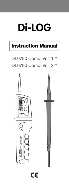
<strong>Di</strong>-<strong>LOG</strong>Instruction ManualDL6780 Combi Volt 1DL6790 Combi Volt 2
DL6780/DL6790 Instruction ManualContents1) Introduction2) Safety notices3) Instrument layoutCarrying out Measurements4) Voltage test AC/DC5) Single pole voltage indication6) Continuity test7) Phase rotation test8) Maintenance9) Specification1) IntroductionThank you for purchasing a <strong>Di</strong>-Log voltage continuitytester. This tester has been designed in accordancewith the latest international safety standards.The combivolt testers are fully automatic voltageindicators capable of measuring AC/DC voltage up to690 V. Both units have visual and acoustic continuityindicationConstructed in accordance with IEC 61010 and IEC 61243-3.• Single pole phase indication• 2 pole phase rotation indication• LED& LCD display (DL6790)2) Safety noticesThis manual contains information that must be followedfor operating the meter safely and maintaining themeter in a safe operating condition. If this meter is notused in the manner specified, the protection providedmay be impaired.Warning! Warns of potential danger, refer to theinstruction manual to avoid personal injury ordamage to the meter.
Caution! Dangerous voltage. Danger of electricalshockContinuous double or reinforced insulationcomplies with IEC536, class 11CE Symbol of conformity, confirms conformity withrelevant EU directives. The meter complies with EMCdirectives (89/336/EEC). Specifically standards EN50081-1 and EN 50082-1 as well as the Low Voltage<strong>Di</strong>rective (73/23/EEC) described in the standard EN61010-1.The meter has been designed in accordance with thesafety regulations for electronic measuringinstruments, EN 61010-1, IEC 61010Voltages above 75V DC or 50V AC may constitute aserious shock hazard.Before using the meter check for physical damage tothe casing in particular around the connectors. If thecase is damaged do not use the meter.Check the test probes for damaged insulation orexposed metal. Check the leads for continuity.Do not apply more than the rated voltage, as markedon the meter between the terminals or between anyterminal and ground.Do not use or store the meter in an environment of hightemperature, humidity, fumes, vapour, gaseous,inflammable and strong magnetic field. Theperformance and safety of the instrument and the usermay be compromised in such circumstances.<strong>Di</strong>sconnect circuit power and discharge all highvoltage capacitors before testing resistance, continuityand diodes.Remove the batteries if the meter is not in use for a longperiod. Constantly check the battery as it may haveleaked. A leaking battery will damage the meter.The meter may only be opened by a qualified servicetechnician for calibration and repair.
3) Instrument Layout1) Test Probe ( - ) L12) Test Probe (+) L23) LED’s for voltage indication4) LED for single - pole test5) Right & Left LED, phase rotation indication6) LED for continuity7) LCD for voltage display (only DL6790)8) Contact electrode for double-pole test of phaserotation and single-pole test9) Torch button on the back10) Positive LED11) Negative LED12) Battery CompartmentCarrying out measurementsPerform a self test of the unit. Connect the two test probesL1 and L2. The continuity LED (6) will be lit and an audibletone should be heard.Before any test check the unit on a known voltage source.If the unit is defective it should be put out of service andreturned to <strong>Di</strong>-Log for repair.
4) Voltage testAlways hold the test probes by the handles behind thefinger guards.. Observe the safety notices at all times.An audible tone is present when an AC voltage and anegative DC voltage are indicated.The maximum switch on time is 30 s. When this time haselapsed you must wait 10 minutes before retesting.Connect probes to voltage source observing polarity of thetest probes L2 is positive probe, L1 is the negative probe.For AC voltage the value is indicated on the LEDs (3) andon the LCD display (DL6790 only). The + and – LEDs areilluminated and buzzer is audible.For DC voltage connect probe L2 to the positive terminaland L1 to the negative terminal. The voltage is displayed onthe LEDs and the LCD display (DL6790 only). The positiveLED (10) is illuminated. If the polarity is reversed the buzzerwill sound. The negative LED (11) will be illuminated.
5) Single pole voltage detectionPerform a function test prior to this test.This unit can be used as a single pole voltage detectorwhen batteries are inserted.The single pole test is intended only as a quick check. Thecircuit must be checked again for the presence of voltageusing the two pole method.Connect test probe L2 to the voltage source and keepfinger on the contact electrode (8). If an AC voltage above100 V is present the LED (4) is illuminated and the buzzersounds.The single pole test can be negatively affected byunfavourable conditions such as electrostatic field, goodinsulation etc.6) Continuity testThe continuity test is only possible when batteries areinserted and in good condition.Ensure the circuit under test is not live.Connect test probes L1 and L2 to the circuit. The continuityLED (6) will illuminate and the buzzer will sound.The unit will indicate continuity below 400 Kohm
7) Phase rotation testPerform a function test prior to this test.This unit can determine the phase rotation within a threephase supply.Connect test probe L2 to the supposed phase 2 and thetest probe L1 to the supposed phase 1. If the R LE<strong>Di</strong>lluminates the phases are in the correct sequence 1 to 2.
Connect test probe L2 to the supposed phase 3 and testprobe L1 to the supposed phase 2. If the R LE<strong>Di</strong>lluminates the phases are in the correct sequence 2 to 3.Connect test probe L2 to the supposed phase 1 and thetest probe L1 to the supposed phase 3. If the R LE<strong>Di</strong>lluminates the phases are in the correct sequence 3 to 1.During phase rotation test touch the contact electrode.If the L LED illuminates then the phase sequence is anticlockwise.8) MaintenanceDo not attempt to repair this unit . There are no userserviceable items in this unit. Never attempt to open thecasing apart from the battery cover.Do not use the instrument if there is any physical damageto the case or test leads.The outside of the unit can be cleaned with a soft damp clothonly. Do not use abrasive or chemical cleaning agents.Changing batteriesTurn the battery cover by 90 degrees anti clockwise.Remove the cover and take out spent batteries. Replace with2 off 1.5 V AAA (LR03) batteries, checking the correct polarity.Replace the battery cover and turn by 90 0 clockwise.Spent batteries should be disposed of responsibly and withcompliance with current recycling and disposal regulations.CalibrationThe recommended calibration interval for the DL6780/DL6790is 12 months.
9) SpecificationsVoltage DL6780 DL6790Voltage display 12 – 690 V AC/DC 6 – 690 V AC/DCLED Resolution 12, 24, 50, 120, 230, 12, 24, 50, 120, 230,400, 690 400, 690LCD Resolution1 V +/- 3 % + 8 digitsVoltage detection automatic automaticAcoustic signal AC voltage – DC AC voltage – DC voltagevoltagePolarity detection Full range Full rangeResponse time LED < 0.1s LED