Centro-Matic Automated Lubrication Systems
Centro-Matic® Automated Lubrication Systems System ... - Unimaq
Centro-Matic® Automated Lubrication Systems System ... - Unimaq
- No tags were found...

Create successful ePaper yourself
Turn your PDF publications into a flip-book with our unique Google optimized e-Paper software.
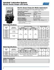
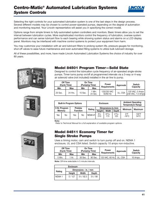
<strong>Centro</strong>-<strong>Matic</strong> ® <strong>Automated</strong> <strong>Lubrication</strong> <strong>Systems</strong>System ControlsSelecting the right controls for your automated lubrication system is one of the last steps in the design process.Several different models may be chosen to control power-operated pumps, depending on the degree of automationand monitoring required. Your Lincoln representative will assist you in specifying the correct model.Options range from simple timers to fully-automated system controllers and monitors. Basic timers allow you to set theinterval between lubrication cycles. More sophisticated monitors control the frequency of lubrication, oversee systemperformance and can sense lubricant flow to each bearing while showing system status and alarms on a LCD displaypanel. Monitors may be interfaced with machine control systems to protect your equipment from harm.You may customize your installation with air and lubricant filters to prolong system life, pressure gauges for monitoring,shut-off valves to ease future maintenance and even automated filling systems to utilize bulk lubricant storage.All of these possibilities, and more, have made Lincoln <strong>Automated</strong> <strong>Lubrication</strong> <strong>Systems</strong> the choice of industry for over80 years.Model 84501 Program Timer—Solid StateDesigned to control the lubrication cycle frequency of air-operated single-strokepumps. Timer turns pump on/off at programmed intervals via a 3-way or 4-wayair solenoid valve (not included) installed in the air line to pump.Off TimeOn Time(Cycle Time) (Pumping Time) PowerApprovals SwitchRequirementsCapacityMin Max Min Max1 Min. 120/230 VAC120 VAC, 5 Amps20 Sec. 24 Hrs. 10 Sec.24 Sec. 50/60 HzUL, CSA230 VAC, 1.5 AmpsBuilt-In Program OptionsEnclosureAmbient OperatingTemperature Range3 Hr. Program PrelubeDimensions-in./mmRatingMinimum MaximumMemory Function Height Width DepthYes No Yes No NEMA #18¹⁄₄ 6¹³⁄₁₆ 4¹⁵⁄₁₆ 0°F 130°F210 173 125 -18°C 54°CNote:Refer to Technical Manual for a full explanation of available program options.Model 84511 Economy Timer forSingle Stroke PumpsUses a timing motor, cam and switch to turn pump off and on. NEMA 1enclosure, UL and CSA listed. Switch capacity 10 amps non-inductive.Off TimeOn Time(Cycle Time) (Pumping Time) PowerApprovals SwitchRequirementsCapacityMin Max Min Max5 Min. 1 Hr. 30 Sec. 90 Sec. 120 VAC, 60 Hz UL, CSA 10 AmpsNote: Off-time selectable in 5 minute intervals.EnclosureDimensions - in. / mmRatingHeight Width DepthNEMA 1 5 / 127 3¹⁄₄ / 82.5 3¹⁄₂ / 8941
<strong>Centro</strong>-<strong>Matic</strong> ® <strong>Automated</strong> <strong>Lubrication</strong> <strong>Systems</strong>System ControlsModel 84015 Timer—12-24V DCSolid-state microprocessor-based controller for automated lubrication systems onmobile equipment or where AC power is not available. Rugged construction withliquid- and dust-tight enclosure. Includes manual push-button for remote initiationof a lube cycle.Off Time**(Cycle Time)Fixed On Time Power Switch(Pumping Time) Requirements CapacityMin.Max.10-30 VDC2.5 Min. 80 Min. 75 Sec.5 Amps25 MA** Less load. ** Available selections are 2.5, 5, 10, 20, 40 or 80 minutes.RatingNEMA 12EnclosureAmbient Operating Temperature RangeDimensions-in. / mmMinimumMaximumHeight Width Depth5¹⁄₄ / 133 3¹⁄₈ / 79 3 / 76 0°F / -18°C 131°F / 55°CModel 85520 Programmable ControllerMicroprocessor-controlled, 120 volt AC unit is fully programmable. Controller hasa wider off-time range than timers and a memory switch to turn pre-lube option onor off.Off Time On Time (Pumping/Switch Capacity(Cycle Time)Alarm Time)Power Inductive Load at 120VACRequirementsMin. Max. Min. Max. Load Relay Alarm Relay30 300 120 VAC 2 230 Sec. 30 HoursSec. Sec. 50/60 Hz Amps AmpsEnclosureAmbient Operating Temperature RangeDimensions-in. / mmRatingMinimumMaximumHeight Width DepthNEMA 12 7¹⁄₂ / 191 4¹⁵⁄₁₆ / 125 3¹⁄₂ / 89 0°F / -18°C 130°F / 55°C* Less load.Model 85525 Programmable ControllerSame as Model 85520 except includes pressure switch and mounting brackets.Model 85535 System Controller—24V DCSame as Model 85520 except is a 24-volt DC.42
<strong>Centro</strong>-<strong>Matic</strong> ® <strong>Automated</strong> <strong>Lubrication</strong> <strong>Systems</strong>System ControlsModel 85530 <strong>Lubrication</strong> System ControllerControls lubrication frequency and monitors supply line pressure. The LCD displaysoperating status.Lube CycleTimer ModeCounter ModeOff-TimeOff-CountsMin. Max. Min. Max.1 . 9,900 1 99,000Minute Minutes Count Counts* Minimum duration of count signal is 33 milliseconds.Max.CountRate*30/Sec.@ 50%DutyCyclePumping TimeBefore AlarmMin. Max.1 99Minute MinutesPower Requirements (less load) Pump, Ambient EnclosureSolenoid, Temperature Dimensions-in. / mmVoltage Current or Alarm Range RatingHeight Width DepthCapacity120 VAC, 50/60 Hz 85 MA230 VAC, 50/60 HZ 45 MA360 VA 32° to 122°F NEMA 9¹⁄₂ 8¹⁵⁄₁₆ 4¹⁄₈0° to +50° C 12 241 227 10524 VDC 250 MA 5 AmpsNote: Model 85530 is CSA/NRTL approved.Model 85209 Panel MountedPneumatic Control SystemPanel mounted units control lubrication frequency and monitor supply line pressure.Includes Model 85530 Controller (specifications above), Model 69630 PressureSwitch and solenoid-operated air valve.Lube CyclePumpingTimer Counter Max. TimeMode Mode Count Before ConnectionsOff Time Off Counts Rate AlarmMin. Max. Min. Max. Min. Max. Air Lube1 9,900 1 99,000 30/ 1 99 ³⁄₈" ³⁄₄"Minute Minutes Count Counts Sec. Minute Minutes NPTF(F) NPTF(F)Power Requirements External Ambient PanelCurrent Alarm Temperature DimensionsVoltage (less load) Load Range in. / mmCapacity Height Width120 VAC, 60 Hz32° to 122°F 12 18¹⁄₄110 VAC, 50 Hz 47 VA 360 VA0° to +50°C 305 464Model 85208Same as Model 85209 except 220 VAC, 50-60 Hz power.43
<strong>Centro</strong>-<strong>Matic</strong> ® <strong>Automated</strong> <strong>Lubrication</strong> <strong>Systems</strong>System ControlsModel 85500 System Sentry IIThe ultimate automated lubrication system controller/monitor now features greatermonitoring accuracy with less sensitivity to lubricant flow rates, feed line length, orbearing back pressure. System Sentry II is always on the job, making sure that everylube point is lubricated when it’s supposed to be.• Solid-state controller with LCD status display and 16-button keypad forsystem programming• Controls up to two pumps with as many as two lube zones per pump• Fully programmable monitoring and alarm functions• Be set up to monitor every lube point for lubricant flow during each lubricationevent• Easy to understand prompts reported by simple English language messages inreal timeSome functions require optional accessories. Use a maximum of 48 sensors andthree accessory Sensor Boards (order separately—16 sensors per board) to monitorlube points.Lube CycleMax. Pumping TimeTimer ModeCounter ModeOff-Time Off-CountsCount Before AlarmNetMin. Max. Min. Max.Rate*Min. Max. Wt.1 9,900 1 99,00030/Sec.1 99 18 lbs.Second Minutes Count Counts@ 50% Second Minutes 8.1 kgDuty Cycle* Minimum duration of count signal is 33 milliseconds.Power Requirements (less load) Pump, Ambient EnclosureSolenoid, Temperature Dimensions-in. / mmVoltage Current or Alarm Range RatingHeight Width DepthCapacity120 VAC, 50/60 Hz 250 MA*230 VAC, 50/60 HZ 125 MA*360 VA 32° to 122°F NEMA 11 14 4⁷⁄₈0° to +50° C 12 241 227 10524 VDC 600 MA* 5 AmpsNote: Model 85500 is CSA/NRTL approved.* No external load, no sensors.44
<strong>Centro</strong>-<strong>Matic</strong> ® <strong>Automated</strong> <strong>Lubrication</strong> <strong>Systems</strong>System ControlsModel 247333 Pressure TransducerPressure Transducer signals actual system pressure via LCD display of SystemSentry II. Comes with 72 inch (1.8m) shielded 24-gauge connecting wire.Maximum length of wire between transducer and monitor is 30 (9.1m) feet.Range Accuracy ProofPressure Ambient VoltageConnection Temp. Input Output OffsetEnclosureNEMA 4X0 to7500 psig ¹⁄₄" NPT -20° to 180° F 10 to 1-6 1 Rating4000 psi±1%517 bar Male Thread -29° to 82° C 30 VDC VDC 300 Series276 bar VDC StainlessSteelModel 250365 Sensor BoardPlug-in accessory board used with Model 85500 that allows the attachment of upto 16 lube flow sensors. (Model 85500 comes without boards installed and canhold up to a total of three.)Sensor AssembliesSensor assemblies consist of a check body and lube sensor with attached 30'cable. Cables are epoxy potted into the sensors for a watertight seal. Sensorshave a 3 ⁄8" pipe thread for conduit connection and a Viton ® O-ring seal. Checkbodies terminate in a 1 ⁄8" NPTF male thread for attachment to a bearing or otherlubricant inlet. Maximum working pressure 6,000 psi (414 bar). Maximum wirerun from sensor to monitor is 500 feet (152m).Min. IntervalLubricant Min. Flow Inlet/Model Description Construction Between LubeTemp. Range Per Event OutletFlow Event250400250490250500250590Straight SensorAssembly90° SensorAssemblyBrass Sensor& Plated SteelCheck BodyStraight Sensor 316Assembly Stainless Steel90° Sensor Sensor &Assembly Check Body32° to 145° F0° to 63° C.004 cu.in./.066 cc@ 32°F / 0° C to125°F / 52°C.008 in 3 / .131cc@ 126ºF / 53ºC to145ºF / 63ºC1/8" 30 SecondsModel 243100 Sensor Wire100 foot (30.5 meters) coil of two conductor 22-gauge wire for connecting sensorsto monitor. Maximum length of wire between sensor and monitor is 500 feet(152 meters).45
<strong>Centro</strong>-<strong>Matic</strong> ® <strong>Automated</strong> <strong>Lubrication</strong> <strong>Systems</strong>System ControlsUse This Guide to Select Accessories forModel 85500 System Sentry IIPressure Pressure Sensor Sensor WireFunction Switch Transducer Board Sensors #243100 (100')#69630 #247333 #250365 Note 2 Note 3Lube Controller1 Pump, 1 Zone Optional 1 Optional 1 — — —Note 1Lube Controller,Required1 Pump, 1 per Zone Required 1 — — —Up to 3 Zones(3 Max.)Lube Controller, Required 22 Pumps, 1 Zone No (1 per Pump) — — —Per PumpLube Controller, Required Required 22 Pumps, Up to 2 1 per Zone (1 per Pump) — — —Zones Per Pump(4 Max.)Lube Point Required Required RequiredMonitoring — — 1 per each 1 per Quantity≤ 48 Points 16 Sensors Lube Point As NeededNote 1: Controller may be operated without a pressure switch or pressure transducer but will not beable to monitor and alarm for lube system pressure failures.Note 2: Sensors include 30' (9.1m) cable pigtail. Select brass/plated steel or stainless steel sensors instraight or 90° configuration as required.Note 3: Maximum distance between monitor and sensor is 500' (152 meters).46
<strong>Centro</strong>-<strong>Matic</strong> ® <strong>Automated</strong> <strong>Lubrication</strong> <strong>Systems</strong>System ControlsElectric Solenoid-Operated Air ValvesElectrical CharacteristicsModel TypePower Inrush Holding Air Ambient Cv Max. ConduitRequirements Current Current Inlet/ Temperature Factor Pressure ConnectionAmps Amps Outlet Range psi / bar110 VAC, 50 Hz350244 120 VAC, 60 Hz .11 .074-Way8.4 VA 0° to 120°F220 VAC, 50 Hz -18° to 49°C1.2350245 240 VAC, 60 Hz .055 .0358.4 VA 1⁄4" 1⁄2" NPS(F)110 VAC, 50 Hz NPT(F)350241 120 VAC, 60 Hz .11 .078.4 VA 150220 VAC, 50 Hz 10.3350242 240 VAC, 60 Hz .055 .035 .183-Way 8.4 VA12 VDC 0° to 140°F3502826 Watts1⁄8" -18° to 60°CN/A N/A24 VDC NPT(F)3502836 WattsN/A68586 2-Way120V, 60 Hz3⁄8"12 VA.2 .1 NPT(F)2.4 1⁄2" NPT(F)274398 3-Way24 VDC1N/A N/A⁄4"8.5 Watts NPT(F).5 N/A244727 3-Way110 VAC, 50 Hz 3⁄8"0° to 120°F120 VAC, 60 Hz .12 .09 NPT(F)-18° to 49°C11 VA4.4 1⁄2" NPT(F)Model 249605 Sealed Cycle TimerSealed timer attaches to Lincoln 16:1 Hydraulic Pumps and generates timed pulsesignal to control pump reciprocating cycle rate.PowerCycle Rate/MinuteRequirement Min. Max.24 VDC 6 6047
<strong>Centro</strong>-<strong>Matic</strong> ® <strong>Automated</strong> <strong>Lubrication</strong> <strong>Systems</strong>System ControlsEnd-of-Line MonitorsDesigned to detect system pressure utilizing normally open or normally closedswitch.Switch Operating Range - psig / bar Lube Dimensions - in / mm ConduitModelRating Min. Max. Inlet Height Width Connection83898 125, 250 1200 / 83 2500 / 172 ¹⁄₄"480 VAC, NPTF(F) 5³⁄₄ / 146 2¹⁄₄ / 57 ¹⁄₂" NPSM83899 15 Amps 700 / 48 1150 / 79Model 83354 Signal MonitorDesigned to provide visual and audible indication of system operation and failure.Utilizes signal from system controller. Includes Model 69606 Alarm Horn mountedon enclosure door.Indicator LampsPowerRequirementPower Lube SystemOn System On Failure115 VAC50/60 Hz Green Amber Red35 VANote: Lamps and horn are U.L. listed.AudibleDimensions - in / mmAlarm Height Width Depth69606 Horn 10 8 6(included) 254 203 152Model 69630 Pressure SwitchSenses supply line pressure rise/fall to signal system operation to controller orsystem alarm.Switch Capacity Adjustable Range - psig / bar ConnectionsType Decreasing IncreasingACDCLube ElectricalMin. Max. Min. Max.15 Amps @ 6 VDC ²⁷⁄₃₂" hole10 Amps atSingle5 Amps @ 24 VDC 250 2775 280 3000for ¹⁄₂"Contact125, 250 or.03 Amps @ 17 191 19 207 ¹⁄₄" NPT(F) conduit480 VDC250 VDC connectorNote: Pressure switch has a NEMA 3 housing and UL listed switching elements.48