technical documentation - Hinrichs Electronic
technical documentation - Hinrichs Electronic
technical documentation - Hinrichs Electronic

Create successful ePaper yourself
Turn your PDF publications into a flip-book with our unique Google optimized e-Paper software.
TECHNICAL DOCUMENTATION<br />
for the<br />
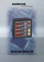
PROGRAMMABLE INTERVAL TIMER<br />
I 3<br />
<strong>Hinrichs</strong> <strong>Electronic</strong> GmbH<br />
Creidlitzer Straße 68<br />
D-96450 Coburg<br />
Phone: + 49 / (0)9561 / 18400<br />
Fax: + 49 / (0)9561 / 28522<br />
Email: info@hinrichs-electronic.de
Note for the user<br />
We should like to make it clear from the outset that these devices are used in<br />
many different machines. Because we mainly supply the control to machine<br />
manufacturers and like to maintain intensive customer service, we are only<br />
too happy for customers to request program adaptations and circuit changes<br />
requiered for the different types of machine from us. In this way, is can be ensured<br />
that user-friendly operation is provided for the user.<br />
If certain features that are important for the user, such as modified operation,<br />
or additional functions are integrated into the control, these are described in<br />
the Section "Options and Modifications".<br />
The functions marked * in the Operating Instructions are optional and not integrated<br />
into every control.<br />
2
TABLE OF CONTENTS<br />
1. SYSTEM DESCRIPTION<br />
1.1 FEATURES ............................................................................................5<br />
1.2 FUNCTIONS OF THE DISPLAY AND THE KEYBOARD.......................5<br />
2. OPERATING INSTRUCTIONS<br />
2.1 START-UP............................................................................................ 10<br />
2.2 PROGRAMMING.................................................................................. 10<br />
2.2.1 Programming program numbers 01 to 49.................................................................... 10<br />
2.2.2 Programming program numbers 50 to 99................................................................... 11<br />
2.2.3 Programming program number 00............................................................................... 12<br />
2.3 STARTING / STOPPING THE PROGRAM .......................................... 13<br />
2.3.1 Starting the program .................................................................................................... 13<br />
2.3.2 Stopping the program................................................................................................... 14<br />
2.4 OPERATION AFTER FAILURE OF THE POWER SUPPLY................ 15<br />
3. TECHNICAL DATA<br />
3.1 SUPPLY VOLTAGE ............................................................................. 16<br />
3.2 AMBIENT CONDITIONS ...................................................................... 17<br />
3.3 HOUSING AND DIMENSIONS............................................................. 18<br />
3.4 MOUNTING NOTES............................................................................. 18<br />
3.5 CONNECTION ASSIGNMENT............................................................. 19<br />
3.5.1 Block diagram .............................................................................................................. 19<br />
3.5.2 Outputs......................................................................................................................... 19<br />
3.5.3 Rear view ..................................................................................................................... 20<br />
3
4. GENERAL INFORMATION<br />
4.1 MAINTENANCE ................................................................................... 21<br />
4.1.1 Cleaning ....................................................................................................................... 21<br />
4.1.2 Battery back-up ............................................................................................................ 21<br />
4.2 WARRANTY CONDITIONS ................................................................. 22<br />
4.3 REPAIR AND COMPONENT REPLACEMENT SERVICE................... 22<br />
4.4 TRANSPORT DAMAGE....................................................................... 22<br />
4.5 SAFETY INFORMATION...................................................................... 23<br />
5. OPTIONS AND MODIFICATIONS<br />
4
1. SYSTEM DESCRIPTION<br />
The I3 Interval Timing System switches connected machines (tumblers) on and off at programmed<br />
intervals for a set time.<br />
1.1 Features<br />
- Up to 99 programs can be programmed, stored and called up.<br />
The user can store the following data under a program number:<br />
- Total time<br />
- Massage time<br />
- Pause time<br />
* - Vacuum time<br />
* - Aeration time<br />
• Depending on the software version, the vacuum, aeration interval ist activated<br />
either<br />
during the total time<br />
or<br />
only during the pause time<br />
- Another special feature of this timer ist that several consecutive programs can be chained.<br />
1.2 FUNCTION OF THE DISPLAY AND THE KEYBOARD<br />
5
The display with large high-luminosity display elements informs the user about all important data during<br />
the execution phase. All input keys are located on the clearly laid out membrane keypad.<br />
The front panel is subdivided into the following function blocks:<br />
PROGRAM<br />
Display field<br />
6<br />
The display field "PROGRAM" is used to<br />
locate the requiered program.<br />
During the execution phase, the number of the program currently being executed is displayed.<br />
In programming mode, the number of the program whose data are being entered or changed is<br />
displayed.<br />
Key<br />
PROGRAM<br />
Nr.<br />
If you press the key, the program number on the display is incremented.
MASSAGE TIME<br />
Display field<br />
7<br />
This is used to set the massage time. This<br />
is the time during which the drum is in motion.<br />
Times from 1 minute to 99 minutes<br />
can be set.<br />
During the execution phase, the current massage time to go is displayed. If the pause time is active<br />
during execution, this display remains off.<br />
In programming mode, the required massage time (setpoint) is displayed.<br />
Key<br />
In programming mode, the key is used to set the massage time. If you press the key, the time is<br />
incremented.<br />
PAUSE TIME<br />
Display field<br />
This is used to set the pause time. This is<br />
the time during which the drum is motionless.<br />
Times from 1 minute to 99 minutes<br />
can be set.<br />
During the execution phase, the current pause time to go (actual value) is displayed. If the massage<br />
time is active during execution, this display remains off.<br />
In programming mode, the required pause time (setpoint) is displayed.<br />
Key<br />
MASSAGE TIME<br />
PAUSE TIME<br />
min<br />
min<br />
In programming mode, the key is used to set the pause time. If you press the key, the time is incremented.
* VACUUM TIME<br />
Display field<br />
During the execution phase, the vacuum time<br />
8<br />
There is no separate function field for this<br />
function. The vacuum time is set in the function<br />
field for massage time.<br />
This is the time during which a connected<br />
vacuum pump creates a vacuum in the<br />
drum. Times from 1 minute to 99 minutes<br />
can be set.<br />
In programming mode, the required vacuum time (setpoint) is displayed in the massage time display<br />
field.<br />
Key<br />
In programming mode, the massage time key is used to set the vacuum time. If you press the key,<br />
the time is incremented.<br />
• AERATION TIME<br />
Display field<br />
During the execution phase, the aeration time (actual value) is not displayed.<br />
There is no separate function field for this<br />
function. The aeration time is set in the function<br />
field for pause time.<br />
This is the time during which a connected<br />
valve is opened to equalize the pressure in<br />
the drum. Times from 1 minute to 99 minutes<br />
can be set.<br />
In programming mode, the required aeration time (setpoint) is displayed in the pause time display<br />
field.<br />
Key<br />
MASSAGE TIME<br />
PAUSENZEIT<br />
min<br />
min<br />
In programming mode, the pause time key is used to set the aeration time. If you press the key, the<br />
time is incremented.
TOTAL TIME<br />
Display field<br />
During the execution phase, the current time to go is displayed.<br />
In programming mode, the requiered execution time is set.<br />
Key<br />
TOTAL TIME<br />
9<br />
This field is used to set the execution time.<br />
Times between 1 hour and 99 hours or<br />
between 1 minute and 99 hours can be<br />
set depending on the software version.<br />
In programming mode, the key is used to set the execution time in hours. * or in hours and minutes<br />
with certain software versions.<br />
FUNCTION KEYS<br />
C<br />
PROG<br />
START<br />
STOP<br />
h min<br />
Correction key „C“<br />
This key is used during programming to correct values that have<br />
been entered incorrectly.<br />
Programming key „PROG“<br />
This key is used to select and exit the programming mode.<br />
„START“ key<br />
This key is used to start a selected program.<br />
„STOP“ key<br />
This key is used to stop or interrupt a running program.
2. OPERATING INSTRUCTIONS<br />
2.1 START-UP<br />
The program control is activated when the supply voltage for the connected machine is switched on.<br />
Normally the value 0 will be shown in the display fields after a delay of approximately 2 seconds.<br />
2.2 PROGRAMMING<br />
Programs can be programmed and stored under the numbers 01 to 99.<br />
2.2.1 PROGRAMMING PROGRAM NUMBERS 01 TO 49<br />
PROGRAM<br />
Note:<br />
Nr<br />
10<br />
To do this, select the program number that<br />
is to be programmed or changed using the<br />
„program number“ key.<br />
If you habe to correct a value while entering data, you can do this using the „C“ key. Press the „C“ key<br />
briefly and then the key of the function block where you want to correct the value. The value 0 appears<br />
in the display. You can now enter the new value.<br />
When the decimal point at the units position of the program number lights up, this indicates that values<br />
have been entered or changed in that program.
MASSAGE TIME<br />
PAUSE TIME<br />
TOTAL TIME<br />
The required massage time is entered using the<br />
„PROG“ and the „MASSAGE TIME“ keys. Hold the<br />
„PROG“ key down and press the „MASSAGE<br />
TIME“ key.<br />
The required pause time is entered using the<br />
„PROG“ and the „PAUSE TIME“ keys. Hold the<br />
„PROG“ key down and press the „TOTAL TIME“<br />
key.<br />
The required total time is entered using the „PROG“<br />
and the „TOTAL TIME“ keys. Hold the „PROG“ key<br />
down and press the „TOTAL TIME“ key.<br />
* On units with vacuum control, the values for vacuum and aeration time must also be entered.<br />
This is done as follows.<br />
PROGRAM<br />
min<br />
min<br />
MASSAGE TIME<br />
PAUSE TIME<br />
h min<br />
Nr<br />
min<br />
min<br />
PROG<br />
PROG<br />
PROG<br />
PROG<br />
PROG<br />
2.2.2 PROGRAMMING PROGRAM NUMBERS 50 TO 99<br />
Press the program number key briefly.<br />
Once the key has been pressed, the „program number“<br />
concerned is still shown in the program number<br />
display. The display fields „massage time“ and<br />
„pause time“ normally show 0, unless values have already<br />
been programmed under this number.<br />
The function field „massage time“ is now used to enter<br />
the vacuum time.<br />
To enter the time hold the „PROG“ key down and<br />
press the „MASSAGE TIME“ key.<br />
The function field „massage time“ is now used to enter<br />
the aeration time.<br />
To enter the time hold the „PROG“ key down and<br />
press the „PAUSE TIME“ key.<br />
11
Using these program numbers it is possible to chain up to ten programs. This has the advantage that<br />
several programs can be executed one after the other. The following program numbers can be<br />
chained:<br />
Program numbers 50 to 59<br />
Program numbers 60 to 69<br />
Program numbers 70 to 79<br />
Program numbers 80 to 89<br />
Program numbers 90 to 99<br />
Each program number is programmed as described in Section 2.2.1.<br />
But please heed the following points:<br />
- The program numbers must be adjacent<br />
e.g. program number 52,53,54<br />
- Several program blocks can be chained in one program number block.<br />
e.g. in program number block 80 to 89<br />
Program 80, 81<br />
Program 83, 84, 85<br />
Program 87, 88, 89<br />
- A chained program must be terminated by writing the value 0000 into the total time of the<br />
next program number.<br />
e.g. program numbers 70, 71, 72, 73 are chained if the value 0000 is stored in the total value of<br />
the following program number – i.e. program number 74.<br />
No terminating program number is required if the last program number is also the last program<br />
number of the block.<br />
e.g. program numbers 77, 78, 79 – the program number 79 can be used for a program. 0000 does<br />
not have to be stored in the total time of program number 79.<br />
2.2.3 PROGRAMMING PROGRAM NUMBER 00<br />
If the program number is 00, data entry is possible without pressing the PROG key. This is used to<br />
test programs.<br />
Note:<br />
The values entered only remain stored until the machine is switched off or another program is executed.<br />
12
2.3 STARTING / STOPPING THE PROGRAM<br />
PROGRAM<br />
2.3.1 STARTING THE PROGRAM<br />
During the execution phase, the time currently being executed is displayed.<br />
To do this, select the number of the program you<br />
want to start by pressing the „program number“<br />
key.<br />
Press the „START“ key to start the program.<br />
The decimal point in the display field „Total time“<br />
starts to blink at one-second intervals.<br />
* On certain versions of the unit it is possible to have the program start after a certain time.<br />
* STARTING THE PROGRAM WITH LEAD TIME<br />
PROGRAM<br />
TOTAL TIME<br />
Nr.<br />
START<br />
Nr.<br />
h min<br />
START<br />
To do this, select the number of the program you<br />
want to start by pressing the „program number“<br />
key.<br />
Set the required lead time in the display field „total<br />
time“ using the „total time“ key.<br />
If you press the „total time“ key, the two display fields<br />
„massage time“ and „pause time“ are unlit. The program<br />
number display remains visible and you can<br />
now set the required lead time in the display field „total<br />
time“.<br />
Depending on the software version, times between 1<br />
hour and 99 hours or 1 minute and 99 minutes<br />
can be entered.<br />
Press the „START“ key to start the program.<br />
Once the lead time has elapsed, the actual execution<br />
cycle of the set program number is started.<br />
Lead times are not stored and must therefore be entered before every program start.<br />
13
2.3.2 STOPPING THE PROGRAM<br />
STOP<br />
START<br />
STOP<br />
14<br />
You can stop a program before the end with the<br />
„STOP“ key. After you have pressed the key, the<br />
displays start to blink.<br />
You can restart the program from the point where<br />
it was interrupted with the „START“ key.<br />
If you want to stop the program altogether, you<br />
can do this with the STOP"“key.<br />
Caution !<br />
During programs with vacuum control there<br />
might still be an underpressure in the drum!
2.4 OPERATION AFTER FAILURE OF THE POWER SUPPLY<br />
The program control is equipped with a protective circuit. The values are also saved if the unit has<br />
failed during program execution as the result of a power failure (including program number 0).<br />
After voltage recovery, the function of the program control depends on the position of the slide switch<br />
on the rear of the housing.<br />
In switch position "1" ...<br />
After a power failure all values in the displays start blinking.<br />
In switch position "2" ...<br />
15<br />
If you want the program to be executed without<br />
change, press the „START“ key.<br />
If you want the program to be stopped press the<br />
"„STOP" key.<br />
The program control automatically continues to execute the working cycle after power recovery.<br />
Caution!<br />
START<br />
STOP<br />
With the functions „automatic start after power recovery“ and * “execution with lead time“ the<br />
machine is switched on automatically.<br />
In both cases, the relevant regulations of the VDE and the Statutory Industrial Accident Insurance<br />
Institution or equivalent national institutions must be observed!
3. TECHNICAL DATA<br />
3.1 SUPPLY VOLTAGE<br />
The units can be supplied in different versions with different operating voltages.<br />
Caution!<br />
Before connecting the control, compare the supply voltage for the unit with the rating plate!<br />
The rating plate is located on the rear of the unit.<br />
The unit is equipped with an electronic voltage-monitoring function. When the unit is switched on the<br />
circuit checks the magnitude of the operating voltage. If it is 10% higher than that stated on the rating<br />
plate the unit cannot be switched on.<br />
Electrical connection values:<br />
Voltage: 24V AC +/-10%<br />
or<br />
220V AC +/-10%<br />
Power consumption: max. 10VA<br />
Frequency: 49,5Hz to 60,5Hz<br />
The operating voltage is connected at the 3-way connector of the unit.<br />
16
3.2 AMBIENT CONDITIONS<br />
Temperature:<br />
Operation: -10 to +45 C<br />
Storage: -25 to +70 C<br />
Relative air humidity:<br />
Operation: 10% to 80% without condensation<br />
Storage: 5% to 85% without condensation<br />
Shock resistance:<br />
Operation: up to 0.5 G within 1 ms<br />
Storage: up to 1.0 G within 1 ms<br />
Vibration resistance:<br />
Operation: up to 0,25 G at max. 55 Hz<br />
Storage: up to 0,5 G at max. 55 Hz<br />
Weight: 1,5 kg<br />
17
3.3 HOUSING AND DIMENSIONS<br />
The unit is supplied as a complete unit in a mounting housing ready for connection.<br />
Housing material: Acc. To DIN 4370 out of heat-resistant Noryl SE 1<br />
Colour: Black<br />
Mounting: Using screw clamps<br />
Dimensions: Length: 144 mm<br />
Width: 144 mm<br />
Depth: 85 mm<br />
3.4 MOUNTING NOTES<br />
When mounting the program control there are some important points to observe. We therefore request<br />
you to read this section through before performing any mounting work and to observe the<br />
points stated in it.<br />
Check the mounting conditions before mounting the unit. If the operating part (switching cubicle) in<br />
which the unit is to be mounted is installed immediately on the machine, ensure that no vibration or<br />
shocks can affect the unit.<br />
The size of the cut-out required to mount the unit is 136.5 mm x 136.5 mm. These dimensions must<br />
be observed precisely to ensure that the unit is seated firmly.<br />
Concave front doors must be straightened.<br />
Before mounting the unit insert the seal provided between the front door and the unit. Fix the unit<br />
using fixing clamps.<br />
After mounting, check that the seal between the unit housing and the front door is good.<br />
The ventilation slots on the left and right side walls and on the bottom of the housing must not be<br />
covered!<br />
18
3.5 CONNECTION ASSIGNMENT<br />
3.5.1 Block diagram<br />
9 5 3 1<br />
Interval End of program *Vacuum time *Aeration time<br />
7 8 6 4 2<br />
Drive motor End of program *Vacuum pump *Aeration valve<br />
3.5.2 Outputs<br />
Isolated relay outputs (changeover contacts)<br />
Contact material: Silver – gold-flashed<br />
Contact load:<br />
Max. switching voltage: 300V DC / 250V AC<br />
Max.switching current: 1 A<br />
Max.switching power: 200W / 200 VA<br />
19
Note:<br />
The standard version of the unit is equipped with one interval relay (changeover contact) and one<br />
end-of-program relay (NO contact).<br />
* On the version with vacuum control, the unit is also fitted with a vacuum relay (NO contact)<br />
and an aeration relay (NO contact).<br />
Due to the plant-specific differences of individual machine manufacturing companies, there are also a<br />
large number of other variations.<br />
A label is stuck over the 9-way terminal block on the rear of the unit in the factory to indicate contact<br />
assignments which deviate from the standard.<br />
Any additional or changed functions are indicated in Section “Options and Modifications” where necessary.<br />
Standard assignment of the 9-way terminal block without and with * vacuum control<br />
3.5.3 Rear view<br />
*Vacuum *Aeration End of program Interval<br />
1 2 3 4 5 6 7 8 9<br />
20
4. GENERAL INFORMATION<br />
4.1 MAINTENANCE<br />
Note: The membrane keyboard consists of a high-quality, non-reflective polyester<br />
membrane. If the membrane is damaged by improper use, the unit<br />
must be sent for repair.<br />
4.1.1 Cleaning<br />
The only preventive maintenance required is to clean the membrane keyboard.<br />
Before you do this, disconnect the system from the mains power supply to ensure that you<br />
cannot start the machine unintentionally.<br />
You can now clean the front membrane using a mild cleaning agent. Make sure that no liquid enters<br />
the unit.<br />
Caution! Do not use coarse cloth or volatile solvents such as alcohol or paint thinners.<br />
4.1.2 Battery back-up<br />
High quality memory components with an integrated lithium battery are used in production. The<br />
manufacturer of these components guarantees continuous data storage for at least 10 years.<br />
To prevent loss of data, we recommend sending the unit in for inspection after an operating time of<br />
approx. 8 years.<br />
21
4.2 WARRANTY CONDITIONS<br />
Every unit undergoes a stringent quality test before leaving production. Nearly all early failures are<br />
detected in intermittent operation. However, it is possible that a component might fail only after a long<br />
period of operation. In accordance with the General Conditions of Supply for Products and Services<br />
of the German Electrical Industry, we grant a 12 month warranty on condition that the unit is not<br />
modified in any way. In repairs of all types we make every effort not to change or delete the programs<br />
entered by the user but we do not guarantee this. The user must therefore check that the programs<br />
are correct before starting up the unit. Faults due to improper installation or mounting<br />
are not covered by the warranty!<br />
4.3 REPAIR AND COMPONENT REPLACEMENT SERVICE<br />
For warranty claims, repair and component replacement service, we recommend our in-house facilities.<br />
We provide first-hand service with short delivery times. If you have a claim, attach a note to the<br />
housing of the unit with a brief description of the fault. Then add your name and telephone number<br />
and we will be able to deal with your claim quickly. We recommend use of the original packaging<br />
when sending units be post, rail or road.<br />
4.4 TRANSPORT DAMAGE<br />
It is advisable to inspect the unit for mechanical damage and loose parts inside immediately after<br />
unpacking it. If transport damage is found, inform the carrier immediately. In case of doubt, ask the<br />
supplier.<br />
22
4.5 SAFETY INFORMATION<br />
Please read the information in the instructions and mounting notes carefully before starting<br />
up the unit. This information is important for the installation, operation and maintenance of<br />
the unit.<br />
Keep the operating instructions in a safe place for possible subsequent owners.<br />
The manufacturer accepts no liability if the following instructions are not observed.<br />
Packaging Dispose of the packaging material in a proper manner.<br />
Use Only use the unit for its specified purpose.<br />
Mounting Observe the installation instructions - see the description Section<br />
3.3. If the unit has to be remounted after repair or inspection,<br />
make sure that the seal between the housing of the unit and the front<br />
door of the switchgear cubicle is good. Worn or porous rubber<br />
seals must be replaced.<br />
Electrical connection The electrical connection conditions and specifications must<br />
match those on the rating plate.<br />
Electrical connection, start-up, possible measurements during<br />
repair and fuse replacement must only be performed by a<br />
trained electrician who is aware of the dangers involved.<br />
Caution!<br />
Before opening and closing the housing, the unit must be disconnected<br />
from all voltage sources.<br />
Unit fuse Before replacing or checking the fuse element, disconnect the<br />
unit from the mains power.<br />
Do not on any account use fuse elements with a higher current<br />
rating than that specified!<br />
Ventilation slots To avoid heat accumulation in the unit, ensure that the ventilation<br />
slots in the right-hand and left-hand side walls and in the bottom of<br />
the housing are never covered.<br />
Humidity All the printed circuit boards in the unit are covered with protective<br />
paint in the factory. This affords them better protection from humidity<br />
than conventional boards.<br />
However, despite this preventive measure, we strongly advise you<br />
not to allow liquid of any kind to enter the housing through the ventilation<br />
slots of the unit.<br />
Used units Units taken out of service must be rendered unusable immediately ....<br />
Disposal and disposed of in the proper manner.<br />
23
Subject to changes due to <strong>technical</strong> advance without prior notice.<br />
This description is for information only and is not binding unless expressly confirmed by us<br />
in writing.<br />
We reserve the right to change the specification, version, price and delivery time of the product<br />
described at any time.<br />
Our contribution to the protection of the environment - we use recycled paper.<br />
24
5. Options and Modifications<br />
25
View of display<br />
26