Ransburg
Turbodisk2 Applicator (Serv. Man. LN-9240-02.1) - Ransburg
Turbodisk2 Applicator (Serv. Man. LN-9240-02.1) - Ransburg

Create successful ePaper yourself
Turn your PDF publications into a flip-book with our unique Google optimized e-Paper software.
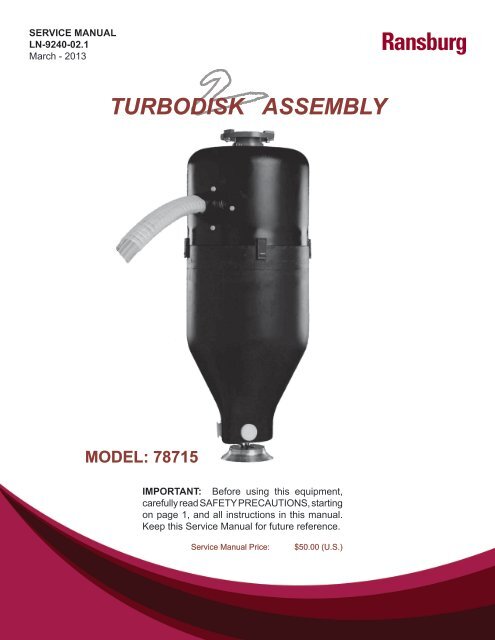
SERVICE MANUALLN-9240-02.1March - 2013<strong>Ransburg</strong>TURBODISK ASSEMBLYMODEL: 78715IMPORTANT: Before using this equipment,carefully read SAFETY PRECAUTIONS, startingon page 1, and all instructions in this manual.Keep this Service Manual for future reference.Service Manual Price:$50.00 (U.S.)
Turbodisk 2 - Contents<strong>Ransburg</strong>CONTENTSSAFETY: 1-4SAFETY PRECAUTIONS .......................................................................................................1HAZARDS / SAFEGUARDS ..................................................................................................2-4GENERAL SAFETY GUIDELINES .........................................................................................5-7INTRODUCTION: 8-11PAGEFEATURES..............................................................................................................................8GENERAL DESCRIPTION .....................................................................................................8SPECIFICATIONS ..................................................................................................................9TYPICAL SPEED CHART (RPM’S) ........................................................................................10-11INSTALLATION: 12-15EQUIPMENT ..........................................................................................................................12AIR CONTROL .......................................................................................................................12MOUNTING ............................................................................................................................12INTERLOCKS ........................................................................................................................12TYPICAL TURBODISK 2 DRIVE AIR SYSTEM & AIR LOGIC CONTROL PANEL ................13UPPER TURBODISK 2 BULKHEAD PLATE ..........................................................................14TURBODISK 2 SIGNAL / PORT IDENTIFICATION TABLE ...................................................15OPERATION: 16-19COATING MATERIALS ..........................................................................................................16FLUID FLOW CONTROL .......................................................................................................16FLUID VALVE CONTROL .......................................................................................................17FLUID & AIR PRESSURE REQUIREMENTS ........................................................................17TURBINE SPEED ..................................................................................................................18ELECTROSTATIC VOLTAGE .................................................................................................19TARGET DISTANCE ..............................................................................................................19MAINTENANCE: 20-31GENERAL ..............................................................................................................................20CLEANING PROCEDURES ...................................................................................................20-21VIBRATION NOISE ................................................................................................................22TURBINE REPAIR & REBUILD ..............................................................................................22VALVES & REGULATORS .....................................................................................................22PREVENTIVE MAINTENANCE .............................................................................................22DISASSEMBLY PROCEDURES ............................................................................................23-26TROUBLESHOOTING GUIDE ...............................................................................................27NO VALVE APPLICATION SCHEMATIC ................................................................................283-WAY VALVE APPLICATION SCHEMATIC ..........................................................................29TRIGGER / DUMP w/REGULATOR SCHEMATIC .................................................................30TRIGGER / DUMP w/REGULATOR (DR-1) SCHEMATIC .....................................................31(CONTINUED ON NEXT PAGE)LN-9240-02.1
<strong>Ransburg</strong>Turbodisk 2 - ContentsCONTENTS (Cont.)PAGEPARTS IDENTIFICATION: 32-69TURBODISK 2 ASSY MODEL IDENTIFICATION ................................................................. 32-35TURBODISK 2 ASSY, NO VALVES / PARTS LIST. ............................................................... 36-37TURBODISK 2 ASSY, 3-WAY VALVE / PARTS LIST ............................................................ 38-39TURBODISK 2 ASSY, TRIGGER & DUMP VALVE W/FLUID REGULATOR / PARTS LIST ........ 40-41TURBODISK 2 ASSY, TRIGGER & DUMP VALVE W/DR-1 FLUID REGULATOR / PARTS LIST ...... 42-43LOWER TURBODISK 2 FLUID CONTROL ASSEMBLY / PARTS LIST ............................... 44-45UPPER TURBODISK 2 BULKHEAD PLATE & FAIRING MOUNTING / PARTS LIST .......... 46-47FLUID SUPPLY LINE PACKAGE / PARTS LIST ................................................................... 48-493-WAY VALVE ASSY / PARTS LIST ...................................................................................... 50-51HIGH FLOW FLUID REGULATOR ASSY / PARTS LIST ...................................................... 52-53DR-1 FLUID REGULATOR ASSY / PARTS LIST .................................................................. 54-55DR-1 FLUID REGULATOR ASSY / PARTS LIST .................................................................. 56-57TURBODISK 2 AIR HEATER / PARTS LIST ......................................................................... 58-59TURBODISK 2 QUICK RELEASE FAIRING ASSY / PARTS LIST ........................................ 60-61TRIGGER & DUMP VALVE ASSY / PARTS LIST .................................................................. 62-63BULKHEAD PLATE FITTING LAYOUT / PARTS LIST .......................................................... 64-65TURBODISK 2 AIR TURBINE ASSY / PARTS LIST ............................................................. 66-69WARRANTY POLICIES: 70LIMITED WARRANTY ............................................................................................................70APPENDIX: 71-74PAINT AND SOLVENT SPECIFICATIONS .............................................................................71VISCOSITY CONVERSION CHART ......................................................................................72-73VOLUMETRIC CONTENT OF HOSE OR TUBE ...................................................................74LN-9240-02.1
Turbodisk 2 - Safety<strong>Ransburg</strong>SAFETYSAFETY PRECAUTIONSBefore operating, maintaining or servicing any<strong>Ransburg</strong> electrostatic coating system, readand understand all of the technical and safetyliterature for your <strong>Ransburg</strong> products. Thismanual contains information that is important foryou to know and understand. This informationrelates to USER SAFETY and PREVENTINGEQUIPMENT PROBLEMS. To help you recognizethis information, we use the following symbols.Please pay particular attention to these sections.A WARNING! states information to alert youto a situation that might cause serious injuryif instructions are not followed.A CAUTION! states information that tells howto prevent damage to equipment or how toavoid a situation that might cause minor injury.A NOTE is information relevant to theprocedure in progress.While this manual lists standard specificationsand service procedures, some minor deviationsmay be found between this literature and yourequipment. Differences in local codes and plantrequirements, material delivery requirements, etc.,make such variations inevitable. Compare thismanual with your system installation drawingsand appropriate <strong>Ransburg</strong> equipment manualsto reconcile such differences.!W A R N I N GThe user MUST read and be familiar withthe Safety Section in this manual and the<strong>Ransburg</strong> safety literature therein identified.This manual MUST be read and thoroughlyunderstood by ALL personnel whooperate, clean or maintain this equipment!Special care should be taken to ensure thatthe WARNINGS and safety requirementsfor operating and servicing the equipmentare followed. The user should be aware ofand adhere to ALL local building and firecodes and ordinances as well as NFPA 33SAFETY STANDARD, 2000 EDITION, priorto installing, operating, and/or servicing thisequipment.!W A R N I N GThe hazards shown on the followingpage may occur during the normal use ofthis equipment. Please read the hazardchart beginning on page 2.Careful study and continued use of this manual willprovide a better understanding of the equipmentand process, resulting in more efficient operation,longer trouble-free service and faster, easiertroubleshooting. If you do not have the manualsand safety literature for your <strong>Ransburg</strong> system,contact your local <strong>Ransburg</strong> representative or<strong>Ransburg</strong>.1LN-9240-02.1
<strong>Ransburg</strong>Turbodisk 2 - SafetyAREATells where hazardsmay occur.Spray AreaGeneral Use andMaintenanceHAZARDTells what the hazard is.Fire HazardImproper or inadequate operationand maintenance procedureswill cause a fire hazard.Protection against inadvertentarcing that is capable of causingfire or explosion is lost if any safetyinterlocks are disabled duringoperation. Frequent power supplyshutdown indicates a problem inthe system requiring correction.Improper operation ormaintenance may create ahazard.Personnel must be properlytrained in the use of thisequipment.SAFEGUARDSTells how to avoid the hazard.Fire extinguishing equipment must be present inthe spray area and tested periodically.Spray areas must be kept clean to prevent theaccumulation of combustible residues.Smoking must never be allowed in the spray area.The high voltage supplied to the atomizer must beturned off prior to cleaning, flushing or maintenance.When using solvents for cleaning:Those used for equipment flushing should haveflash points equal to or higher than those of thecoating material.Those used for general cleaning must have flashpoints above 100 o F (37.8 o C).Spray booth ventilation must be kept at the ratesrequired by NFPA 33, 2000 Edition, OSHA and localcodes. In addition, ventilation must be maintainedduring cleaning operations using flammable orcombustible solvents.Electrostatic arcing must be prevented.Test only in areas free of combustible material.Testing may require high voltage to be on, but onlyas instructed.Non-factory replacement parts or unauthorizedequipment modifications may cause fire or injury.If used, the key switch bypass is intended for useonly during setup operations. Production shouldnever be done with safety interlocks disabled.Never use equipment intended for use in waterborneinstallations to spray solvent based materials.Personnel must be given training in accordancewith the requirements of NFPA 33, Chapter 16,2000 edition.Instructions and safety precautions must be readand understood prior to using this equipment.Comply with appropriate local, state, and nationalcodes governing ventilation, fire protection,operation maintenance, and housekeeping. OSHAreferences are Sections 1910.94 and 1910.107.Also refer to NFPA 33, 2000 edition and yourinsurance company requirements.LN-9240-02.12
Turbodisk 2 - Safety<strong>Ransburg</strong>AREATells where hazardsmay occur.ElectricalEquipmentHAZARDTells what the hazard is.High voltage equipment is utilized.Arcing in areas of flammable orcombustible materials may occur.Personnel are exposed to highvoltage during operation andmaintenance.Protection against inadvertentarcing that may cause a fire orexplosion is lost if safety circuitsare disabled during operation.Frequent power supply shutdownindicates a problem in the systemwhich requires correction.An electrical arc can ignitecoating materials and cause afire or explosion.SAFEGUARDSTells how to avoid the hazard.The power supply, optional remote control cabinet,and all other electrical equipment must be locatedoutside Class I or II, Division 1 and 2 hazardousareas. Refer to NFPA No. 33, 2000 Edition.Turn the power supply OFF before working onthe equipment.Test only in areas free of flammable or combustiblematerial.Testing may require high voltage to be on, butonly as instructed.Production should never be done with the safetycircuits disabled.Before turning the high voltage on, make sure noobjects are within the sparking distance.ExplosionHazard /IncompatibleMaterialsHalogenated hydrocarbonsolvents for example: methylenechloride and 1,1,1,-Trichloroethaneare not chemicallycompatible with the aluminumthat might be used in manysystem components. Thechemical reaction caused bythese solvents reacting withaluminum can become violentand lead to an equipmentexplosion.Aluminum is widely used in other spray applicationequipment - such as material pumps, regulators,triggering valves, etc. Halogenated hydrocarbonsolvents must never be used with aluminumequipment during spraying, flushing, or cleaning.Read the label or data sheet for the material youintend to spray. If in doubt as to whether or not acoating or cleaning material is compatible, contactyour material supplier. Any other type of solventmay be used with aluminum equipment.ToxicSubstancesCertain material may be harmfulif inhaled, or if there is contactwith the skin.Follow the requirements of the Material Safety DataSheet supplied by coating material manufacturer.Adequate exhaust must be provided to keep theair free of accumulations of toxic materials.Use a mask or respirator whenever there is achance of inhaling sprayed materials. The maskmust be compatible with the material being sprayedand its concentration. Equipment must be asprescribed by an industrial hygienist or safetyexpert, and be NIOSH approved.3LN-9240-02.1
<strong>Ransburg</strong>Turbodisk 2 - SafetyAREATells where hazardsmay occur.Spray Area /High VoltageEquipmentHAZARDTells what the hazard is.There is a high voltage devicethat can induce an electricalcharge on ungrounded objectswhich is capable of ignitingcoating materials.Inadequate grounding will causea spark hazard. A spark canignite many coating materialsand cause a fire or explosion.SAFEGUARDSTells how to avoid the hazard.Parts being sprayed must be supported onconveyors or hangers and be grounded. Theresistance between the part and ground must notexceed 1 megohm.All electrically conductive objects in the spray area,with the exception of those objects required by theprocess to be at high voltage, must be grounded.Any person working in the spray area must begrounded.Unless specifically approved for use in hazardouslocations, the power supply and other electricalcontrol equipment must not be used in Class 1,Division 1 or 2 locations.PersonnelSafety /MechanicalHazardsThe disk atomizer can rotate atspeeds up to 40,000 RPM. Atthese speeds, the edge of theapplicator can easily cut into skin.Loose articles can also be caughtby the rotating disk.Personnel must stay clear of the disk wheneverit is rotating.Before touching the disk, the turbine air must beshut off.If the disk has been rotating, allow at least threeminutes for it to come to a complete stop beforetouching it.LN-9240-02.14
Turbodisk 2 - SafetyGENERAL SAFETYGUIDELINES!W A R N I N GThe simple safety measures outlinedhere are vital. Failure to observe them couldcause a spark capable of starting a fire.• The articles being coated MUST be groundedat all times.• All components of the applicator system (exceptthe atomizing head) MUST be grounded at alltimes.• All contact points MUST be free of any accumulationof nonconductive residue.• All electrically conductive objects, especiallysolvent containers within the spray area, MUSTbe either removed or grounded.Any tool, if used improperly, can be dangerous.Safety is ultimately the responsibility of those usinga tool. In like manner, safe operation of electrostaticcoating processes is the responsibility of thosewho use such processes and those who operateelectrostatic coating equipment. Procedures tobe followed on conducting electrostatic coatingoperations safely are outlined in the <strong>Ransburg</strong>brochure IL-247: "Operating Your ElectrostaticCoating System Safely". Additional copies areavailable from <strong>Ransburg</strong> upon request. All personnelconnected with coating operations shouldread and understand this brochure. It is mostimportant that the equipment operators and supervisorypersonnel understand the requirementsfor safe operation.!W A R N I N GIf ANY symptom of improper operationoccurs, suspend use of the unit until theproblem has been diagnosed and corrected.See the appropriate "TroubleshootingGuide" or contact your <strong>Ransburg</strong> representative.<strong>Ransburg</strong>Additional cards summarizing these safety requirementsare available from <strong>Ransburg</strong> on request.These cards should be posted in the sprayingarea so that they can be readily referred to andserve as a reminder to personnel in that area ofresponsibility. Additional copies of the sign SL-00-07: "Cleaning Safety Requirements" are availableupon request.Each user should examine his own coating operation,develop his own safety program, andensure that his workers follow correct procedures.<strong>Ransburg</strong> hopes that the information it provides ishelpful to the user in establishing such a program.In addition to the available cards, labels, brochures,and service manuals, the user should consult otherstandards and recognized safety authorities. Section1910.107 of the regulations established underthe Occupational Safety and Health Act [OSHA]apply to spray finishing operations. Paragraph (i)specifically applies to electrostatic hand sprayingequipment. NFPA No. 33 "Spray Application", isanother standard for spray painting operations.Chapters 9, 10, and 13 are specifically applicableto electrostatic coating. Copies of NFPA No. 33are available from the National Fire ProtectionAssociation, Batterymarch Park, Quincy, Mass.02269 (at nominal cost).The National Fire Protection Association alsopublishes standards other than NFPA No. 33 relatingto the control of fire hazards. NFPA No. 33specifically refers to the following bulletins of theNational Fire Protection Association as applicableto coating operations:NFPA No.63: Dust Explosion, Industrial PlantsNFPA No.70: National Electrical CodeNFPA No.86A: Ovens and FurnacesNFPA No.91: Blower and Exhaust SystemsNFPA No.654: Dust Explosions, Plastics IndustryNFPA No.77: Static Electricity, also contains muchuseful information. Copies of these brochureswill be helpful in arriving at a program for safeoperation.5LN-9240-02.1
<strong>Ransburg</strong>Turbodisk 2 - SafetyLocal codes and authorities also have standardsto be followed in the operation of your sprayequipment. Your insurance carrier will be helpfulin answering questions that arise in your developmentof spray coating procedures.All personnel MUST read and understand thefollowing <strong>Ransburg</strong> Safety Publications:IL-247: Operating Your Electrostatic CoatingSystem Safely SL-77-01: Personnel Grounding<strong>Ransburg</strong> also suggests that all personnel readthe HEW publication "Spray Painting: GoodPractices for Employees", number (NIOSH) 78-178 available from the regional NIOSH office orthe U.S. Government Printing Office.NIOSH and OSHA regional offices can provideinformation on OCCUPATIONAL SAFETY ANDHEALTH ACT, including questions on standardsinterpretations, voluntary compliance information,copies of the OSHA Standards, OSHA Act,Employee Rights Posting Notice and Publications.Personnel!W A R N I N GALWAYS turn power supply OFF prior tocleaning or working on equipment.ENSURE that the grounding hook hasbeen properly secured to the motor housing.• All personnel should read and understand localcodes, appropriate NFPA bulletins, OSHA Actof 1970, and this service manual.• Personnel working in the spray area MUST beadequately grounded. Insulated shoes such asrubber, composition, or cork soles should NOTbe worn unless an alternate grounding methodis provided. (See <strong>Ransburg</strong> Bulletin SL-77-01,"Personnel Grounding".)• Personnel working on applicators MUST alwaysbe sure that the high voltage is off, the rotatorhas stopped and that the grounding hook hasbeen properly secured to the motor housing.Parts• Articles being painted MUST be grounded atALL times. Paint MUST NEVER be permittedto accumulate on workholders, particularly onpoints where workholders touch conveyor.Hooks MUST be clean to ensure proper contact.It is advisable to have extra sets of workholdersto enable cleaning of the sets not being usedat regular intervals. Areas of hanger contactshould be sharp points or edges where possible.• All electrically conductive objects within thespray area (including spray booth, paint tank,and conveyor) MUST BE GROUNDED. Thisrequirement applies to the solvent safetycontainer, paint containers, wash cans, and allother objects in the area.VentilationWe recommend interlocking the ventilation with thespraying equipment to ensure proper ventilationwhen equipment is in operation. See NFPABulletin No. 33.Housekeeping• Good housekeeping is essential to safe operation.Clean-up and maintenance schedules should beestablished by the user, based on observationsof the initial production operations. Maintenanceand safety cards should be posted in clear viewof the operator.• Normal fire protection measures are required.These include proper storage of paints, solvents,and waste, plus ready access to fire extinguishingequipment. For details, consult NFPA BulletinsNo. 30, 33, 70 and 77, your local fire codes, localpaint equipment standards, OSHA Act of 1970,and your insurance carrier’s recommendations.LN-9240-02.16
Turbodisk 2 - Safety<strong>Ransburg</strong>Floor Covering and MaskingIf it is necessary to cover booth flooring, <strong>Ransburg</strong>suggests that the user employ a material whichwill NOT support combustion, such as Spark GardGrade BWA-100.NOTES:Halogenated Hydrocarbons!W A R N I N GA chemical reaction, resulting in thepossibility of a pressure EXPLOSION, mayoccur if 1,1,1-Trichloroehtane, MethyleneChloride, or other Halogenated Hydrocarbonsolvents are used in PRESSURIZABLEFLUID SYSTEMS having ALUMINUM orGALVANIZED WETTED PARTS. Such anexplosion could cause DEATH, seriousBODILY INJURY, and/or substantial propertydamage. See <strong>Ransburg</strong> Bulletins:SL-81-05: HHC Explosion Hazard DangerSignSL-81-08: HHC Explosion Hazard SafetyBulletinConsult your fluid supplier to determine thechemical content of your solvents.7LN-9240-02.1
<strong>Ransburg</strong>Turbodisk 2 - IntroductionINTRODUCTIONFEATURESFeatures which make the Turbodisk TM 2 Applicatoradvantageous for use in electrostatic applicationsinclude:• Proven turbine motor reliability.• Serrated edge conical disk provides excellentatomization quality at minimal rotational speeds.• Aerodynamic fairing design for ease of cleaningof external surfaces.• Speed readout (or control) uses reliable magneticpickup for fiber-optic transmission of rotationalspeed data. (optional)• A majority of all assembly components whichcome in contact with the fluid material are madeof either stainless steel or, which is imperviousto most fluids.• Negligible maintenance down time. With thequick disconnect feature, the lower Turbodisk 2fluid section can be exchanged in minimal timefor off line maintenance.• Quick disconnect feature allows for other fluidcontrol assemblies to be incorporated whendesired.• The easily removable lower fairing, turbine airmotor assembly, and the externally mountedregulators and fluid valves, make off linemaintenance more efficient and economical.• Control air lines are color coded for ease ofidentification.• Higher fluid delivery rates can be achieved usinga dual feed fluid system.• High flow regulators and fluid valves providefor simultaneous paint push out while solventwashes the feed tube and disk.GENERAL DESCRIPTIONThe Turbodisk 2 Applicator, because of it's highrotational speed, produces finer atomization,improved quality, and higher transfer efficiency withany of the wide variety of coating materials (suchas waterborne and high solids) used in productionfinishing operations. It's speed is controlled byvarying the drive air. The applicator assembly isdesigned for use on vertical overhead mountedreciprocators.Quick Disconnect-REFER TO FIGURES 16, 17, & 26The Turbodisk 2 Applicator is a quick disconnectdesign that allows the lower fluid section that carriesall the fluid/ air controls to be separated from theupper section carrying the tubing supply lines. Theincoming air lines, fluid lines, high voltage cable,and fiber optic cable are connected to the fittingsprovided on the upper fixed bulkhead plate. Eachbulkhead plate (upper and lower) utilizes specialmale and female fittings with o-rings that seal thefluid and air line passages when both sections areassembled together. Two latching mechanismshave been incorporated into the design allowingthe lower section to be supported while theoperator tightens or loosens the retaining screwsthat hold the upper and lower sections together.Alignment arrows engraved into the side of thebulkhead plates provide for quick visual assemblyorientation.Conical Disk AssemblyThe Turbodisk 2 Applicator uses conical diskassemblies that are made from high gradealuminum construction and are force balanced to.10 grams•in or better. With the serrated edge,these disks come in sizes of 6, 9, and 12 inchdiameters.LN-9240-02.18
Turbodisk 2 - IntroductionTurbodisk 2 Fairing-REFER TO FIGURE 24The Turbodisk 2 Applicator fairing is required forsafe operation. The two piece fairing provides highvoltage isolation from the metal rotator assemblyand valve components, as well as ease of cleaningand maintenance. Provided on the fairing are (4)draw latches which allow for easy on/off removalof the lower fairing.!W A R N I N GBoth sections of the fairing to be in placewhen the Turbodisk 2 is in operation or whenhigh voltage is supplied to the applicator.Paint Valve OptionsFour paint valve options in single or dual feedapplications are available:• No Valves (refer to Figures 7,12,18)• 3-Way On/Off Valve (refer to Figures 8,13,19)• Trigger and Dump Valve with High Flow Regulator(refer to Figures 9,14,20,25)• Trigger and Dump Valve with Low FlowRegulator (refer to Figures 10,15,21,22,25)Power Supply and ControlsIn the system, the high voltage is supplied to theTurbodisk 2 by either the MicroPak Industrialpower supply system or a Voltage Master seriespower supply.The MicroPak Industrial power supply usesproven high voltage generator technology thatis microprocessor controlled for diagnostics andcommunication. The controller is packaged instandard rack mounted Eurocard format for easyaccess and system integration.The Voltage Master power supplies are generalpurpose heavy duty power supplies with yearsof proven reliability. They have variable voltagecontrol, many safety features, and remote analogvoltage control capabilities.SPECIFICATIONSMechanicalTurbine Speed:Turbine Type:Weight:Length:Diameter:Turbine Air:<strong>Ransburg</strong>Variable to 40,000 rpmmax. (6" conical disk)Ball Bearing57 lbs. (approximately)36 in.13.25 in.At max. speed (40krpm),requires 103.1 psi and61.1 scfm, unloaded(see Figure 1)Fluid PressureInlet: See Figure 4Single Fluid Flow Range:Waterborne: To 1,200 cc/min.Solvent Base: To 1,500 cc/min.High Solids: To 1,000 cc/min. (80%+)Air Inlet Trigger/Dump:70-100 psiAir Pilot for FluidPressure: See Figure 4ElectricalPower Supply Type: MicroPak TM Industrialor Voltage Master TMCharging Method:Input Voltage:Direct0-100 kVTurbine SpeedControl or Monitor: PulseTrack TM (Optional)9LN-9240-02.1
<strong>Ransburg</strong>Turbodisk 2 - IntroductionNOTES:TYPICAL SPEED CHART(RPM's)-REFER TO FIGURES 1 & 23The following represents data collected under labconditions. Flow meters were installed on eachof the two 3/8 I.D. heated air lines used to supplythe Turbodisk 2 turbine motor. The airflow througheach flow meter was recorded and added togetherto obtain the total air flow through the system.The speed of the disk was monitored through themeans of a PulseTrack system. The air heaterwas set at 120 degrees during all data collection.Rotational speeds are unloaded and can beexpected to drop 20 to 30% when under a fluid loadcondition. Heated turbine air increases efficiencyof motor up to 10%. This chart should be usedas a guide ONLY. Speeds will vary due to rotatorwear, tubing size or lengths, etc.NOTENever run disk over it's maximum safeoperating speed.LN-9240-02.110
Turbodisk 2 - Introduction<strong>Ransburg</strong>TYPICAL SPEED CHART - 10 HOLE ORIFICE PLATE6" Conical DiskDisk Speed(RPM)Supply AirPressure (PSI)Air Flow #1(SLPM)Air Flow #2(SLPM)Total Air Flow(SLPM)Total Air Flow(SCFM)5,0006.61401002408.510,00010.519014033011.715,00018.226020046016.220,00027.834026060021.225,00040.444035079027.930,00056.35604601,02036.035,00076.47306101,34047.340,000103.19308001,73061.19" Conical DiskDisk Speed(RPM)Supply AirPressure (PSI)Air Flow #1(SLPM)Air Flow #2(SLPM)Total Air Flow(SLPM)Total Air Flow(SCFM)5,00011.320014034012.010,0002633025058020.513,00039.543034077027.216,00055.45604601,02036.019,00079.87606401,40049.422,0001029308001,73061.112" Conical DiskDisk Speed(RPM)Supply AirPressure (PSI)Air Flow #1(SLPM)Air Flow #2(SLPM)Total Air Flow(SLPM)Total Air Flow(SCFM)2,0008.717012029010.24,00018.627020047016.66,00031.037029066023.38,00048.350040090031.810,00068.56705601,23043.412,00095.88807501,63057.612,500102.09307801,71060.4Figure 1: Typical Speed Chart - 10 Hole Orifice Plate11LN-9240-02.1
<strong>Ransburg</strong>Turbodisk 2 - InstallationINSTALLATIONEQUIPMENTThis system should be installed by, or underthe supervision of an <strong>Ransburg</strong> representative.Should the need arise to replace any componentassembly within the system, contact your <strong>Ransburg</strong>representative.This manual concerns normal operation,maintenance, and service of the specifiedapplicator assemblies. The air and fluidconnections vary with different models andinstallations. This manual deals primarily withthose at, or within the assembly.AIR CONTROL-REFER TO FIGURE 2Air control of the applicator is from a standard<strong>Ransburg</strong> air logic panel, which includes two filters(one 40 micron filter located at the air logic stationand one 5 micron filter located at the inlet of thein-line air heater panel). Clean, dry factory airmust be provided to the inlet filter of the air logicstation via a minimum 1/4-inch I.D. pipe and tothe inlet filter of the heater panel via a minimum3/4-inch I.D. pipe.MOUNTING-REFER TO FIGURE 17 & 24The Turbodisk 2 assembly is mounted on thereciprocator using (4) 5/16-18 screws providedon the ram flange. Loosening (2) 1/4-20 screwson the same ram flange will allow the assemblyto rotate. Position the Turbodisk 2 assembly sothat the strain relief boot is positioned toward theincoming fluid and air lines and retighten.Remove lower fairing by releasing the (4) quickrelease draw latches. Thread all the required air,high voltage, fiber optic, and fluid service linesthrough the strain relief boot. The strain reliefboot may have to be cut larger in order to feed allthe lines through. Refer to the 78718 assembly/schematic diagram for connection reference toupper bulkhead plate.Reinstall lower fairing. Install conical disk andtorque to 50-60 lb•in.INTERLOCKSFlow of coating material should be locked outunless all of the following conditions are met:1. Booth exhaust is turned on.2. The turbine is spinning.3. High voltage is on or in the bypass mode.LN-9240-02.112
Turbodisk 2 - Installation<strong>Ransburg</strong>Figure 2: Typical Turbodisk 2 Drive Air System and Air Logic Control PanelTYPICAL TURBODISK 2 DRIVE AIR SYSTEM & AIR LOGIC CONTROLPANEL - PARTS LIST (Figure 2)Item # Part # Description Qty1 78170-00 Regulator Assembly, Turbodisk 2 Drive Air (Includes the Following:) 1SSP-6439 Elbow, 1/4 O.D. Tube x 1/4 NPT Male Swivel 2SSV-8221 Regulator, 1/2 NPT Ported, Air Piloted 17819-16 Nipple, 1/2 NPT x 1.5 Long, Brass Pipe 1LS0147 Regulator, 1" Ported, Manual Adj. Air, 0-125 psi, 250 CFM 17596-12 Bushing, 1" NPT x 1/2 NPT, Brass 1GA-316 Gauge, 0-160 psig, 1/4 NPT, Air 141-FP-1021 Nipple, 1" NPT x 3/4 NPT, Hex Reducing 1HAF-503 Air Filter, 3/4 NPT 12 78166-00 Hose Assembly, Compressed Air (Includes the Following:) 178164-00 Hose, 3/4" I.D., Push-Loc Air 5 ft.78165-00 Fitting, Female SAE 45 o Swivel x 3/4" I.D. Hose 23 20222-00 Air Heater Assembly 14 78176-01 Tubing, 1/2" O.D. x .375" I.D., Green Nylon To Suit5 SSM-5805 Air Filter, 1/4 NPT 113LN-9240-02.1
<strong>Ransburg</strong>Turbodisk 2 - InstallationFigure 3a: Upper Turbodisk 2 Bulkhead Plate (Reference Figure 26)LN-9240-02.114
Turbodisk 2 - Installation<strong>Ransburg</strong>TURBODISK 2 SIGNAL/PORT IDENTIFICATION TABLE(Figure 3b)Designation asMarked on BulkheadDescriptionTubing ColorF.OHVP1DP1DLR1HR1LP1SP1RP1TP2DP2DLR2HR2LP2SP2RP2TS1.INS2.INT.A1T.A2Fiber Optic CableHigh Voltage CablePaint #1 DumpPaint #1 Dump LineRegulator #1 HighRegulator #1 LowPaint #1 Supply LinePaint #1 Return LinePaint #1 TriggerPaint #2 DumpPaint #2 Dump LineRegulator #2 HighRegulator #2 LowPaint #2 Supply LinePaint #2 Return LinePaint #2 TriggerSolvent #1 SupplySolvent #2 SupplyTurbine Air #1Turbine Air #2NaturalNaturalRedNaturalOrangeYellowNaturalNaturalGreenBlackNaturalSilverBlueNaturalNaturalNaturalNaturalNaturalGreenGreenFigure 3b: Turbodisk 2 Signal/Port Identification Table15LN-9240-02.1
<strong>Ransburg</strong>Turbodisk 2 - OperationOPERATION!!As with any spray finishing system, operationof the Turbodisk 2 involves properly setting theoperating parameters to obtain the best finishquality for the coating material being sprayed,while maintaining correct operation and reliabilityof the equipment used. Adjustments to operatingparameters, which cover spraying, cleaning andon/off control, include:• Fluid Type• Fluid Flow Rate• Turbine Speed• Electrostatic Voltage• Target DistanceC A U T I O NFluids and lubricants used in this systemmust contain NO silicones!Do NOT operate the unit without an atomizerdisk! Without a disk, overspeed, resultingin premature bearing failure, is possible.The air supplied to the motor must bedry, clean and free of oil or moisture. The atmosphericdew point should be 10 o F or less.The air heater used should be adjusted onlyhigh enough to prevent condensation fromforming on the motor housing or at the exhaustport.W A R N I N GOperators must be fully trained in safeoperation of electrostatic equipment. Operatorsmust read all instructions and safetyprecautions prior to using this equipment(See NFPA 33, Chapter 16).COATING MATERIALSThe Turbodisk 2 can be used with a broad rangeof coating material conductivities. However, withwaterborne paints, it may be necessary to isolatethe paint supply from ground.!W A R N I N GIsolated fluid supplies using either waterborneor highly conductive solvent basecoatings can produce hazardous high voltagedischarges which can cause fires or injuryto personnel.FLUID FLOW CONTROL-REFER TO FIGURES 19-22Fluid flow control is dependent on the valveconfiguration of the Turbodisk 2. If the Turbodisk 2is configured with no valves or a 3-way valve, fluidflow is controlled externally at the paint source.If the Turbodisk 2 is equipped with a regulator,fluid flow can be controlled via the air pilot signal.The high flow and low flow regulators each haveprocedures on how to control and deliver consistentfluid flows. For more information on controllingthe fluid delivery using regulators, refer to thatspecific manual which is included with the system.To check fluid flow rates, the disk must beremoved. See the maintenance section forremoval procedure. The fluid can then be manuallytriggered to measure actual flow in a graduatedbeaker over a specified time period.!W A R N I N GDanger of shock and/or personal injurycan occur. Proper grounding procedures,which are outlined in the <strong>Ransburg</strong> safetybulletins, must be followed. Personnel mustnever work near or perform work on the turbinewhen the turbine is spinning or whenhigh voltage is on.LN-9240-02.116
Turbodisk 2 - Operation<strong>Ransburg</strong>FLUID VALVE CONTROLTrigger and Dump-REFER TO FIGURES 4 & 25The fluid valves in the Turbodisk 2 are actuatedby an air signal. The air pressure must exceed70 psi to assure proper actuation of the valve.Applying air to the valve actuator turns on the fluidflow for that valve.The trigger valve controls the paint flow to the disk.When actuated, paint flows through the valve tothe fluid tube. The disk should be spinning at aRPM speed that is fast enough, (that when fluidis turned on) to enable the fluid to flow throughthe disk paint passage holes and be atomized.The dump valve controls the paint flow through thedump line. When actuated, paint flow is directedto the dump return line. This provides a methodof rapidly removing paint from the incoming linefor cleaning and/or color change. Normally, thedump valve is not actuated at the same time asthe paint trigger valve since the trigger valve isintended to cause the fluid flow to the disk at theprescribed input pressure.FLUID & AIR PRESSUREREQUIREMENTS-REFER TO FIGURE 4Fluid and air pressure requirements are dependenton the fluid trigger valve configuration.No Valves3-Way ON/OFF(18283)Trigger/Dumpw/High Flow(70171-04)RegulatorTrigger/Dumpw/Low FlowDR-1 (74151)Regulator78718-01 thru -1078718-11 thru -2078718-21 thru -3078718-31 thru -xxAir Pilot FluidRegulator------------------------------------100 psi max.100 psiAir Inlet Trig/Dump Valve------------------120 psi max.70-100 psi70-100 psiFluid InletPressure------------------300 psi max.80-100 psi max.80-100 psi max.Solvent Inlet------------------30-60 psi max.30-60 psi max.30-60 psi max.Note: Trigger/dump valves (CCV-403-SS) are rated to 300 psi maximum inlet fluid pressure but are limitedto the lower pressure limit of the fluid regulators.Figure 4: Turbodisk 2 Fluid & Air Pressure Requirements17LN-9240-02.1
<strong>Ransburg</strong>TURBINE SPEEDTurbine speed is determined by the drive airpressure at the rotary atomizer and fluid flow rate.Turbine speed can be closed loop controlledusing the fiber optic speed transmitter mountedat the back of the turbine rotator assembly as aspeed input to remote speed controls such as thePulseTrack.NOTEThe disk rotational speed determinesthe quality of atomization and canbe varied for different flow rates and viscosities.For optimum transfer efficiencyand spray pattern control, the disk rotationalspeed should be set at the minimumrequired speed to achieve properatomization. Excessive speed reducestransfer efficiency!!W A R N I N GDo not exceed the maximum rated speedof 40,000 RPM for the 6 inch conical diskand 27,000 RPM for the 6 inch uni-disk.Atomizers-REFER TO FIGURE 5!Turbodisk 2 - OperationW A R N I N GNever operate any disk atomizer in excessof it's maximum rated speed ("K"number) as listed in the service manual.Excessive speed may cause the disk to disintegrate,causing serious damage and/orinjury.All atomizers manufactured after April 6, 1982,bear a “K” number. That number indicates themaximum safe rotation speed for that series intens of thousands. For example:9K = 9,000 RPM maximum safe speed,40K = 40,000 RPM, etc.If you have an atomizer that does not have a “K”number, contact your <strong>Ransburg</strong> representative forits maximum safe operating speed.TYPICAL MAXIMUM SAFE OPERATING SPEEDSAtomizer Disk6" Uni-Disk8" Uni-Disk10" Uni-Disk12" Uni-Disk6" Conical9" Conical12" ConicalPart Number19830-0619830-0819830-1019830-1220485-6220485-9220485-12xFigure 5: Typical Maximum Safe Operating SpeedsMax. RPM27,00023,00015,00015,00040,00025,00020,000LN-9240-02.118
Turbodisk 2 - Operation<strong>Ransburg</strong>ELECTROSTATIC VOLTAGENOTES:In the system, the high voltage is supplied to theTurbodisk 2 by either the MicroPak Industrialpower supply system or Voltage Master seriespower supplies.The MicroPak Industrial power supply usesproven high voltage generator technology thatis microprocessor controlled for diagnostics andcommunication. The controller is packaged instandard rack mounted Eurocard format for easyaccess and system integration.The Voltage Master power supplies are generalpurpose heavy duty power supplies with yearsof proven reliability. They have variable voltagecontrol, many safety features, and remote analogvoltage control capabilities.TARGET DISTANCEThe distance between the Turbodisk 2 and thetarget will affect the finish quality, penetration andefficiency. Closer distances give wetter finishesand greater efficiency, while greater distancesgive drier finishes. The recommended normaldisk edge to target range is 12 inches minimumfor optimum performance.19LN-9240-02.1
<strong>Ransburg</strong>Turbodisk 2 - MaintenanceMAINTENANCEGENERALVerify daily that the operating parameters havenot varied dramatically. A sudden change or evena gradual decay in performance could be earlyindications of component failure.Normal maintenance procedures should beestablished and recorded at the initial startup.All maintenance schedules are subject tovariation based on use. Periodically review thesemaintenance schedules as equipment ages andneeds change.CLEANING PROCEDURES!W A R N I N GElectrical shock and fire hazards can existduring maintenance. The power supplymust be turned off before entering the sprayarea. Spray booth fans should remain onwhile cleaning with solvents.Never touch the disk atomizer while it isspinning. The edge of the disk can easilycut into human skin, gloves or other materials.Be sure the disk atomizer has completelystopped spinning before attemptingto touch it. Approximate time for the disk tostop spinning after turning off the drive air isabout three minutes.!C A U T I O NDo not immerse the Turbodisk 2 assemblyin solvent or other liquids. Turbine componentswill be damaged.Do not soak the disk in solvent longerthan 24 hours.Internal Fluid Path CleaningWith the high voltage turned off and the diskspinning, flush cleaning solvent through theincoming paint line or through the solvent inlet line.If it is desired to clean just the face of the disk off,flush solvent through the solvent inlet. If a colorchange is required, flush the entire system. Thespinning disk will atomize the solvent and clean outthe disk passages. If equipped, trigger the dumpvalve to catch the wasted paint from the incomingline, then flush the disk with solvent after closingthe dump valve.NOTESolvent flushing of the system (exceptduring color change) should be done withthe disk dismounted and with waste solventcollected in a grounded container.In addition to the above Warning, which relates topotential safety hazards, the following informationmust be observed to prevent damage to theequipment.LN-9240-02.120
Turbodisk 2 - Maintenance<strong>Ransburg</strong>External Atomizer SurfaceCleaning!W A R N I N GTo reduce the risk of fire or explosion,OSHA and NFPA 33 require that solvents usedfor exterior cleaning, including disk cleaningand soaking, be nonflammable (flash pointshigher than 100 o F/37.8 o C). Since electrostaticequipment is involved, these solventsshould also be nonpolar. Examples of nonflammable,nonpolar solvents for cleaningare: Amyl acetate, methyl amyl acetate, highflash naphtha and mineral spirits.Do not use conductive solvents such asMEK to clean the external surfaces of theTurbodisk 2.Never lower the Turbodisk 2 assemblyinto a drum for flushing or color changing.Disk CleaningNormally, the internal cleaning instructions willsuffice to clean the disk. If flushing the disk does notremove all the residue, the disk may be removedfor hand cleaning. Unscrew mounting nut andremove the disk by using the supplied disk puller.Inspection of the disk is required to determine ifwear to the serrated edge or damage has occurred.Wear can cause a reduction in transfer efficiencyand excessive paint wrap on the atomizer fairing.NOTEThe turbine shaft must be held with a7/16” open end wrench while using thedisk puller.Clean the disk by soaking in an appropriate solventto loosen paint residue. Do not soak for morethan a 24 hour period. Use a soft cloth to removethe paint from the surface and a soft bristle brushto remove paint from the well area. The splashplate may need to be removed to clean the paintwell. The screws must be retorqued to 24 lb•inafter cleaning.Reinstall the disk and torque the mounting nut to50-60 lb•in.!W A R N I N GDo not attempt to clean the disk edgewhile it is rotating. Do not attempt to slowdown or stop the disk by holding a rag or agloved hand against the edge. This couldcause physical harm and/or damage to thedisk.!C A U T I O NDo not use abrasive materials which willscratch or damage the disk. Cleaning padsshould not be used.Using an atomizer disk with paint buildupmay cause an imbalance. This may resultin bearing damage and turbine failure. Thiscondition may also stress the disk when operatingat high speeds.Before reinstalling the disk onto the shaft,check and clean the tapered mating surfacefor paint residue.Care must be taken when mountingthe disk assembly to the motor shaft. Themounting nut should turn freely for severalturns until it fully bottoms on the disk assembly.! W A R N I N GDo not hold disk edge during removal.This could result in injury.21LN-9240-02.1
<strong>Ransburg</strong>VIBRATION NOISETurbodisk 2 - MaintenancePREVENTIVE MAINTENANCEIf the Turbodisk 2 is vibrating or making an unusualloud noise, it may mean that there is an unbalancedsituation or a bearing failure. The disk could havedried paint or could be damaged. This situationshould be corrected immediately. Do not continueto operate a noisy turbine.!W A R N I N GIf a disk has been mishandled or thereappears to be damage on the face, DO NOTUSE. Serious injury can result from rotatinga defective disk. If there is a concern aboutthe condition of a disk, please return it to<strong>Ransburg</strong> for evaluation.TURBINE REPAIR &REBUILD-REFER TO FIGURE 27Turbine field repair or rebuild only after factorywarranty expires. Any attempt to disassembleturbine during warranty period will void thewarranty.VALVES & REGULATORS-REFER TO FIGURES 19, 20, 21, & 22No maintenance is normally required on thevalves or regulator other than flushing with solventdaily. Visual inspections should be made on thevalves and regulator on a weekly basis. Shouldthe valve or regulator not function properly, referto the individual manuals for troubleshooting andrepair procedures.Before any shutdown or maintenance, the fluidsystem should be thoroughly flushed. All cleaningshould be done with a minimum of the appropriateclean solvent and clean, soft, lint free rags or softbrushes where indicated.W A R N I N GDo not stop disk rotation by using a ragor gloved hand.Make sure high voltage is off before approachingapplicator.!Follow proper grounding procedures.!C A U T I O NBecause of the hazard of bearing penetration,solvents should be used sparingly.They should never be hosed directly ontothe atomizer, motor housing or fiber opticjuncture.Daily Maintenance!W A R N I N GPersonnel working on applicators MUSTalways be sure that the high voltage is off,the fluid system is flushed and off, the rotatorhas stopped, and that the groundinghook has been properly secured to the motorhousing.• Clean the atomizer disk, motor housing, fairing,and as needed, the peripheral equipmentwith nonpolar high flash point solvents.• To prevent solvent penetration beyond the slinger,a minimal air pressure of 5 to 10 psi should beapplied to the motor in order to maintain a positivepressure. The motor should be run at operatingspeed for several minutes after cleaning to keepany solvent that has accumulated at the sealsfrom penetrating into the motor housing.LN-9240-02.122
Turbodisk 2 - Maintenance<strong>Ransburg</strong>• Inspect the disk edge and face. If damageexists, DO NOT USE. Return it to <strong>Ransburg</strong> forevaluation.• Check the fluid feed tube to make sure it is notrubbing the disk.Weekly Maintenance• Follow the normal daily maintenance schedule,then:• Monitor rotational speed at the control and verifyit is within 5% of target speed.• Monitor high voltage output indicated on thepower supply display. Verify with high voltageprobe and meter.• Remove fairing and clean all internal components:valves, regulators, and tubing. Check tubing forevidence of pin-holes, kinks, and abrasions.• If the muffler needs to cleaned (item is to besolvent cleaned) remove it from the motor. Cleanand dry the muffler before reinstalling it.• Check fluid flows by removing the disk andmanually triggering the paint valve. Measurethe amount of fluid in a graduated beaker overa specific time to determine flow rate.• Clean and inspect the disk face. Look for wear,which can cause poor transfer efficiency andexcessive paint wrap on the atomizer fairing.Disk removal, cleaning and inspection may bedone more or less frequently, depending upon use.DISASSEMBLYPROCEDURESPrior to disassembly, verify the following:• The atomizer disk, valves and regulator havebeen flushed with solvent and purged dry with air.• The disk has stopped rotating.• The air supply to the trigger valves and regulatorhave been turned off.• The fluid and solvent supply have been turnedoff and the pressure has been relieved.• The high voltage has been turned off and themotor housing grounded.Turbine Cartridge Exchange-REFER TO FIGURE 27Removal1. Remove disk mounting nut by holding the rotatorshaft above the disk with a 7/16" open endwrench and unscrewing the mounting nut witha 3/8-inch wrench.2. Install the <strong>Ransburg</strong> 19850-00 disk puller intodisk to remove it.3. Unlatch the four fairing draw latches and carefullyremove lower fairing.!W A R N I N GHandle the disk with caution. The sharpedge can cut even though it is not rotating.4. The lower fluid section of the Turbodisk 2Applicator, containing the turbine cartridge,may now be disconnected for continued offline removal procedures through means of the“quick disconnect” feature incorporated intothe unit.With a 5/16-inch wrench, loosen the six captiveretaining screws used to hold the upper andlower sections together. Note: As the lastscrew releases, the lower unit will drop onlyenough to allow for the bulkhead plates to beseparated. The two latching mechanisms onthe bulkhead plates will hold the unit in placeuntil the operator is ready to move the lowersection to a proper work place.23LN-9240-02.1
<strong>Ransburg</strong>Turbodisk 2 - Maintenance4. The lower fluid section of the Turbodisk 25. Once the lower fluid section is placed in astationary condition, the removal of the cartridgecan be continued.6. Next remove screws holding the fluid tubeassembly.7. With a 7/64-inch wrench, remove six sockethead cap screws, which secures the turbinecartridge to the motor housing.8. Using a 1/16-inch wrench, turn each of the threejack screws, located next to socket head capscrew, clockwise not more than one half turn ata time in sequence to separate the motor fromthe housing.!C A U T I O NFailure to perform this step correctly mayresult in misalignment and possible damage.Use caution in removing cartridge to preventit from falling out of the housing.InstallationAlways check the inside of the motor housingand clean, if required, with a minimum amount ofan appropriate cleaning solvent and a soft cloth.1. Using a 1/16-inch wrench, retract the three jackscrews.2. With o-rings in place on the nozzle plate andhousing, insert the turbine cartridge into motorhousing.!C A U T I O NLightly lubricate o-rings with petroleumjelly before assembly. Fit parts with o-ringsvery carefully. They must not be allowed todistort, unseat or break.3. Secure the rotator assembly to the housing withsix socket head cap screws. Tighten the screwsin sequence until the cartridge is fully engagedinto the housing to prevent misalignment andpossible damage. Torque to 10 lb•in.4. To avoid losing the jack screws during normaloperation, torque to 2-3 lb•in.Turbine Cartridge ServiceThis cartridge is a precision instrument and shouldbe handled with care. The bearings are preloadedto 30 pounds and dynamically balanced to 0.01grams•in or better.NOTEBearings used in this cartridge containspecial grease that is available exclusivelyto <strong>Ransburg</strong>. The purchase ofreplacement bearings from sources otherthan <strong>Ransburg</strong> is not recommended.Turbine field repair or rebuild ONLY after factorywarranty expires. Any attempt to disassembleturbine during the warranty period will void thewarranty.Disassembly-REFER TO FIGURE 281. After turbine cartridge has been removedfrom housing, secure the rotating assemblyby inserting a 1/4-inch wrench, which may besecured in a vise for this procedure, in the hexsocket at the rear end of shaft and removeslinger with a spanner wrench.2. With the 1/4-inch wrench still inserted in the hexsocket at the rear end of shaft, remove hex nutusing a 15/16-inch box end wrench.3. Secure a wheel puller tool to turbine rotator.Rotate the center screw of the tool until therotor is free of the shaft. Remove key.LN-9240-02.124
Turbodisk 2 - Maintenance<strong>Ransburg</strong>4. Using a 5/64-inch wrench, remove the six flathead socket screws which secure bearingretainer to bearing housing. Remove theretainer.5. Support bearing housing, front face down, ontwo parallel supports on the arbor press table.Press shaft from the housing. Remove spacerfrom the shaft.!C A U T I O NThe space between the supports mustbe greater than the outside diameter of frontbearing.6. On the arbor press table, support the assembledshaft/bearing, front end down, on the two parallelsupports. With the bearing faces resting on thesupports, press the shaft free of the bearing.7. Remove rear bearing, spring, spring retainer(wave spring washer, and shims in some oldermodels instead of spring and spring retainer),and bearing spacer from bearing housing. Itmay be necessary to press the bearing fromthe housing using a wood or plastic rod or toolhandle inserted through the bore from the front.!Never use a tool that is harder than thepart it is used on.8. With a 5/64-inch wrench, remove the six flathead socket screws from nozzle plate. Removethe nozzle plate.9. Remove all o-rings.Inspection and Preparation!C A U T I O NC A U T I O NFailure to observe the following cautionswill result in diminished performance andpremature motor failure.• Never use any silicone compound in this system!• Never use any lubrication on the bearings!• Never use any solvent on the bearings!• Never exert force on one race of a bearingassembly that may be transmitted to the otherrace through the bearings! Force and resistancemust always be on the same race in order toprevent damage.• Do not enlarge the nozzle passages duringcleaning, as it will effect performance.• Always observe the specified torque in tighteningfasteners.• Clean all parts thoroughly with an appropriate,clean solvent. Inspect them for wear or damageand replace as required.• Check all flow passages for obstruction,particularly the nozzle plate. Clear as required.• Discard all bearings and o-rings and replace withnew. Lightly lubricate o-rings with petroleumjelly before assembly. Fit parts with o-rings verycarefully. They must not be allowed to distort,unseat, or break.AssemblyNOTETorque the screws to 10 lb•in. Do NOTlubricate o-ring.1. With o-ring in its groove on the rear faceof bearing housing, secure nozzle plate inplace with the six screws.2. Using a press tool device on the arborpress table, place front bearing over therear end of shaft. Insert the shaft into thepress tool rear end down and press theshaft through the bearing until the bearingseats against the shoulder on the shaft.25LN-9240-02.1
<strong>Ransburg</strong>Turbodisk 2 - Maintenance3. Place bearing housing on the arbor presstable, front face up, resting on two parallelsupports.4. Insert the bearing/shaft into the bore ofthe bearing housing. With o-ring in placeagainst it, place bearing retainer over theshaft so that it rests on the bearing. Placethe press tool, large end down, over theshaft so that it rests against the bearingretainer. Press until the bearing seats inthe housing.5. Remove the assembly from the press andsecure the retainer with the six screws.NOTETorque the screws to 10 lb•in.6. From the rear of the assembly, placebearing spacer over the shaft and intothe bore so that it seats against the frontbearing.7. From the rear of the assembly, place springand spring retainer over the shaft and intothe bore over the bearing spacer. In someolder models, shims and a wave springwasher are used in place of the spring andretainer. In those models, place shims andwave spring washer over the shaft and intothe bore.!C A U T I O NThe same number of shims that were removedfrom the assembly MUST be placedinto it or the bearing preload will NOT becorrect! Each unit is individually preloaded.The number of shims used for this purposemay vary from unit to unit. It is therefore necessarythat the same number of shims beinstalled in a repaired unit as were removed.If more than one unit is serviced at one time,be SURE that the shims removed from eachunit are returned to that same unit!8. With the housing assembly, front facedown, resting on two parallel supports onthe arbor table, place the rear bearing overshaft. Be sure that o-ring is in place inits groove in the housing bore. Place thesmall end of the press tool over the end ofthe shaft so that it rests against the innerface of the bearing. CAREFULLY pressthe bearing onto the shaft.!C A U T I O NThe outer face of the bearing should be aslip fit into the bore of the housing. Be carefulthat the bearing does not hang up on theouter edge of the bore during the pressing.9. With the assembly still on the press table,place the turbine rotor, flanged side up, overthe shaft. Insert key into the key slot in theshaft, align it with the key slot in the rotor,and press the rotor down until the key isengaged. With the small end of the presstool against the rotor flange, press it ontothe shaft until it seats.!C A U T I O NIf the key is not secure or is missing, theunit will malfunction!10. Place hex nut and the 15/16-inch box endwrench on the rear end of the shaft. Securethe rotating assembly by inserting a 1/4-inch wrench, which may be secured in avise for this procedure, in the hex socketat the rear end of the shaft. Secure thenut using the box end wrench.11. With the shaft still secured from rotation,screw slinger onto the front end of the shaftand secure it using a spanner wrench.NOTETorque the nut to 350 lb•in.LN-9240-02.126
Turbodisk 2 - Maintenance<strong>Ransburg</strong>TROUBLESHOOTING GUIDEGeneral Problem Cause SolutionFluctuating PatternNot enough back pressureon regulator.See regulator manual for diagnosis.Light Coverage onSome PartsPoor TransferEfficiencyLow CurrentReadingsHigh CurrentReadings / PowerSupply OverloadsPart hangers, hooks, arenot clean.Low voltage.Disk RPM to high.Booth flow to high.Disk edge to part distanceto great.Dirty H.V. contacts.Target distance to close.Conductive paint.Fairing dirty.H.V. cable breakdown.Fluid tube pinholed toground on conductivepaint systems.Isolation mounting roddirty or carbon tracked.a. Clean hangers.b. Check ground continuity. (Must be lessthan 1 Megohm.)Check disk voltage with H.V. probe.Slow disk speed.Reduce booth air flow.Decrease conveyor loop diameter.Clean and/or replace.Check target distance. Ideal target distance is12 inches minimum.Solvent base paint conductivity should be between.05 and 20 megohms on <strong>Ransburg</strong> paint test meter.Clean with nonpolar solvent.Replace cable.Check tubing routing for areas where fluid tubecomes near a ground.Clean with nonpolar solvent or replace.Low VoltagePower SupplyFaulty H.V. switch orjunction tank.H.V. cable.Use following procedure to isolate problem:- Verify power supply output. Refer to powersupply manual for procedure.- Remove the fairing and measure input voltageto the rotator assembly by removing the H.V.cable from the connector fitting and insertingit into the H.V. probe. If voltage is low, replaceH.V. cable with a known good one and retest.- If voltage is still low, check for bad connectionsin the H.V. Junction or Switch Tank. Refer toprocedures in the proper manual.- Reinstall the H.V. cable. Check voltage at therotator housing.Figure 6: Troubleshooting Guide27LN-9240-02.1
<strong>Ransburg</strong>Turbodisk 2 - MaintenanceFigure 7: Typical No Valve Application Schematic - Dual Fluid Supply Option(Reference Figure 12)LN-9240-02.128
Turbodisk 2 - Maintenance<strong>Ransburg</strong>Figure 8: Typical 3-Way Valve Application Schematic - Dual Fluid Supply Option(Reference Figure 13)29LN-9240-02.1
<strong>Ransburg</strong>Turbodisk 2 - MaintenanceFigure 9: Typical Trigger and Dump Valve Application with (High Flow) Fluid Regulator Schematic -Dual Fluid Supply Option (Reference Figure 14)LN-9240-02.130
Turbodisk 2 - Maintenance<strong>Ransburg</strong>Figure 10: Typical Trigger and Dump Valve Application with DR-1 Fluid Regulator Schematic - DualFluid Supply with Recirculating Option (Reference Figure 15)31LN-9240-02.1
<strong>Ransburg</strong>Turbodisk 2 - Parts IdentificationPARTS IDENTIFICATION78715 TURBODISK 2 ASSEMBLYMODEL IDENTIFICATIONTurbodisk 2 Assemblies are available with the various options as follows:Model No. 78715 -xx xxDR-1 Fluid Regulator Ratio Option (See Table B)(Dash # required only when applicable) 4 5Upper & Lower Turbodisk 2 Sections, Fluid ControlParts, and Air Motor (See Table A)Basic Part NumberFigure 11: Turbodisk 2 Assembly Standard Model IdentificationTABLE "A" (Figure 11)Dash #0102030405060708212223BasicTurbodisk 2Assy78718-0178718-0278718-0378718-0478718-0178718-0278718-0378718-0478718-1178718-1278718-13TurbineAir MotorAssy78175-0178175-0178175-0178175-0178175-1178175-1178175-1178175-1178175-0178175-0178175-02Air Heater &Filter/Reg.Assy78781-0078781-0078781-0078781-0078781-0078781-0078781-0078781-0078781-0078781-0078781-00* See "Parts List Bullet Definition Table" on page 37.DiskMountingNut 319836-0119836-0119836-0119836-0119836-0219836-0219836-0219836-0219836-0119836-0119836-01DescriptionNo valves, Down Feed CW, Single Fluid System,3/8 ID Tubing OptionNo valves, Down Feed CW, Single Fluid System,1/4 ID Tubing OptionNo valves, Down Feed CW, Dual Fluid System,3/8 ID Tubing OptionNo valves, Down Feed CW, Dual Fluid System,1/4 ID Tubing OptionNo valves, Down Feed CCW, Single Fluid System,3/8 ID Tubing OptionNo valves, Down Feed CCW, Single Fluid System,1/4 ID Tubing OptionNo valves, Down Feed CCW, Dual Fluid System,3/8 ID Tubing OptionNo valves, Down Feed CCW, Dual Fluid System,1/4 ID Tubing Option3-Way On/Off, Down Feed CW, Single Fluid System,3/8 ID Tubing Option3-Way On/Off, Down Feed CW, Single Fluid System,1/4 ID Tubing Option3-Way On/Off, Down Feed CW, Dual Fluid System,3/8 ID Tubing OptionLN-9240-02.132
Turbodisk 2 - Parts Identification<strong>Ransburg</strong>TABLE "A" (Figure 11) - (Continued)Dash #BasicTurbodisk2 AssyTurbineAir MotorAssyAir Heater &Filter/Reg.AssyDiskMountingNut 3Description111111112242526272841424344454647486178718-1478718-1178718-1278718-1378718-1478718-2178718-2278718-2378718-2478718-2178718-2278718-2378718-2478718-3178175-0278175-1178175-1178175-1278175-1278175-0278175-0278175-0278175-0278175-1278175-1278175-1278175-1278175-0278781-0078781-0078781-0078781-0078781-0078781-0078781-0078781-0078781-0078781-0078781-0078781-0078781-0078781-0019836-0119836-0219836-0219836-0219836-0219836-0119836-0119836-0119836-0119836-0219836-0219836-0219836-0219836-013-Way On/Off, Down Feed CW, Dual Fluid System,1/4 ID Tubing Option3-Way On/Off, Down Feed CCW, Single Fluid System,3/8 ID Tubing Option3-Way On/Off, Down Feed CCW, Single Fluid System,1/4 ID Tubing Option3-Way On/Off, Down Feed CCW, Dual Fluid System,3/8 ID Tubing Option3-Way On/Off, Down Feed CCW, Dual Fluid System,1/4 ID Tubing OptionTrigger & Dump Valve w/Fluid Reg. (High Flow), DownFeed CW, Single Fluid System, 3/8 ID Tubing OptionTrigger & Dump Valve w/Fluid Reg. (High Flow), DownFeed CW, Single Fluid System, 1/4 ID Tubing OptionTrigger & Dump Valve w/Fluid Reg. (High Flow), DownFeed CW, Dual Fluid System, 3/8 ID Tubing OptionTrigger & Dump Valve w/Fluid Reg. (High Flow), DownFeed CW, Dual Fluid System, 1/4 ID Tubing OptionTrigger & Dump Valve w/Fluid Reg. (High Flow), DownFeed CCW, Single Fluid System, 3/8 ID Tubing OptionTrigger & Dump Valve w/Fluid Reg. (High Flow), DownFeed CCW, Single Fluid System, 1/4 ID Tubing OptionTrigger & Dump Valve w/Fluid Reg. (High Flow), DownFeed CCW, Dual Fluid System, 3/8 ID Tubing OptionTrigger & Dump Valve w/Fluid Reg. (High Flow), DownFeed CCW, Dual Fluid System, 1/4 ID Tubing OptionTrigger & Dump Valve w/DR-1 Fluid Reg. (Low Flow),Down Feed CW, Single Fluid System, Non-CirculatingFluid Return, 3/8 ID Tubing Option26278718-3278175-0278781-0019836-01Trigger & Dump Valve w/DR-1 Fluid Reg. (Low Flow),Down Feed CW, Single Fluid System, Non-CirculatingFluid Return, 1/4 ID Tubing Option26378718-3378175-0278781-0019836-01Trigger & Dump Valve w/DR-1 Fluid Reg. (Low Flow),Down Feed CW, Dual Fluid System, Non-CirculatingFluid Return, 3/8 ID Tubing Option26478718-3478175-0278781-0019836-01Trigger & Dump Valve w/DR-1 Fluid Reg. (Low Flow),Down Feed CW, Dual Fluid System, Non-CirculatingFluid Return, 1/4 ID Tubing Option26578718-3578175-0278781-0019836-01Trigger & Dump Valve w/DR-1 Fluid Reg. (Low Flow),Down Feed CW, Single Fluid System, RecirculatingFluid Return, 3/8 ID Tubing Option26678718-3678175-0278781-0019836-01Trigger & Dump Valve w/DR-1 Fluid Reg. (Low Flow),Down Feed CW, Single Fluid System, RecirculatingFluid Return, 1/4 ID Tubing Option26778718-3778175-0278781-0019836-01Trigger & Dump Valve w/DR-1 Fluid Reg. (Low Flow),Down Feed CW, Dual Fluid System, RecirculatingFluid Return, 3/8 ID Tubing Option* See "Parts List Bullet Definition Table" on page 37.33LN-9240-02.1
<strong>Ransburg</strong>Turbodisk 2 - Parts IdentificationTABLE "A" (Figure 11) - (Continued)Dash #BasicTurbodisk2 AssyTurbineAir MotorAssyAir Heater &Filter/Reg.AssyDiskMountingNut 3Description26878718-3878175-0278781-0019836-01Trigger & Dump Valve w/DR-1 Fluid Reg. (Low Flow),Down Feed CW, Dual Fluid System, Recirculating FluidReturn, 1/4 ID Tubing Option26978718-3178175-1278781-0019836-02Trigger & Dump Valve w/DR-1 Fluid Reg. (Low Flow),Down Feed CCW, Single Fluid System, Non-CirculatingFluid Return, 3/8 ID Tubing Option27078718-3278175-1278781-0019836-02Trigger & Dump Valve w/DR-1 Fluid Reg. (Low Flow),Down Feed CCW, Single Fluid System, Non-CirculatingFluid Return, 1/4 ID Tubing Option27178718-3378175-1278781-0019836-02Trigger & Dump Valve w/DR-1 Fluid Reg. (Low Flow),Down Feed CCW, Dual Fluid System, Non-CirculatingFluid Return, 3/8 ID Tubing Option27278718-3478175-1278781-0019836-02Trigger & Dump Valve w/DR-1 Fluid Reg. (Low Flow),Down Feed CCW, Dual Fluid System, Non-CirculatingFluid Return, 1/4 ID Tubing Option27378718-3578175-1278781-0019836-02Trigger & Dump Valve w/DR-1 Fluid Reg. (Low Flow),Down Feed CCW, Single Fluid System, RecirculatingFluid Return, 3/8 ID Tubing Option27478718-3678175-1278781-0019836-02Trigger & Dump Valve w/DR-1 Fluid Reg. (Low Flow),Down Feed CCW, Single Fluid System, RecirculatingFluid Return, 1/4 ID Tubing Option27578718-3778175-1278781-0019836-02Trigger & Dump Valve w/DR-1 Fluid Reg. (Low Flow),Down Feed CCW, Dual Fluid System, RecirculatingFluid Return, 3/8 ID Tubing Option27678718-3878175-1278781-0019836-02Trigger & Dump Valve w/DR-1 Fluid Reg. (Low Flow),Down Feed CCW, Dual Fluid System, RecirculatingFluid Return, 1/4 ID Tubing Option* See "Parts List Bullet Definition Table" on page 37.LN-9240-02.134
Turbodisk 2 - Parts Identification<strong>Ransburg</strong>TABLE "B" (Figure 11)Dash # Description Ratio Ref.Regulator Assy01020304050607080910111213142122232425262728293031323334Non-Circulating Fluid Return DR-1, Single Fluid SystemNon-Circulating Fluid Return DR-1, Dual Fluid SystemNon-Circulating Fluid Return DR-1, Single Fluid SystemNon-Circulating Fluid Return DR-1, Dual Fluid SystemNon-Circulating Fluid Return DR-1, Single Fluid SystemNon-Circulating Fluid Return DR-1, Dual Fluid SystemNon-Circulating Fluid Return DR-1, Single Fluid SystemNon-Circulating Fluid Return DR-1, Dual Fluid SystemNon-Circulating Fluid Return DR-1, Single Fluid SystemNon-Circulating Fluid Return DR-1, Dual Fluid SystemNon-Circulating Fluid Return DR-1, Single Fluid SystemNon-Circulating Fluid Return DR-1, Dual Fluid SystemNon-Circulating Fluid Return DR-1, Single Fluid SystemNon-Circulating Fluid Return DR-1, Dual Fluid SystemRecirculating Fluid Return DR-1, Single Fluid SystemRecirculating Fluid Return DR-1, Dual Fluid SystemRecirculating Fluid Return DR-1, Single Fluid SystemRecirculating Fluid Return DR-1, Dual Fluid SystemRecirculating Fluid Return DR-1, Single Fluid SystemRecirculating Fluid Return DR-1, Dual Fluid SystemRecirculating Fluid Return DR-1, Single Fluid SystemRecirculating Fluid Return DR-1, Dual Fluid SystemRecirculating Fluid Return DR-1, Single Fluid SystemRecirculating Fluid Return DR-1, Dual Fluid SystemRecirculating Fluid Return DR-1, Single Fluid SystemRecirculating Fluid Return DR-1, Dual Fluid SystemRecirculating Fluid Return DR-1, Single Fluid SystemRecirculating Fluid Return DR-1, Dual Fluid System1:21:21:41:41:61:61:81:81:101:101:31:31:11:11:21:21:41:41:61:61:81:81:101:101:31:31:11:178719-0178719-01 & -2178719-0278719-02 & -2278719-0378719-03 & -2378719-0478719-04 & -2478719-0578719-05 & -2578719-0678719-06 & -2678719-1178719-11 & -3178719-4178719-41 & -6178719-4278719-42 & -6278719-4378719-43 & -6378719-4478719-44 & -6478719-4578719-45 & 6578719-4678719-46 & -6678719-5178719-51 & -71* PARTS LIST BULLET DEFINITION TABLE (Figure 11)12345General Application Guideline: Use for fluid flow rates above 750 ml/min.General Guideline: Use for fluid flow rates from 25 to 1500 ml/min.Note: Assemblies using DR-1 fluid regulators (part number 74151-xx)(1) Disk mounting nut (see Table "A") is included with this assembly. When installing disk (not included),torque mounting nut to 50 - 60 lb•in. (Recommended: 3/8" hex bit socket with square drive torquewrench.)DR-1 Non-circulating fluid return applies (see Table "B").DR-1 Recirculating fluid return applies (see Table "B").35LN-9240-02.1
<strong>Ransburg</strong>Turbodisk 2 - Parts IdentificationFigure 12: 78718-04 Turbodisk 2 Assembly, No Valves,Dual Fluid Supply System, 1/4 I.D. Tubing OptionLN-9240-02.136
Turbodisk 2 - Parts Identification<strong>Ransburg</strong>78718-04 TURBODISK 2 ASSEMBLY - PARTS LIST (Figure 12)Item # DescriptionPart #Qty1 Assembly, Basic Lower Turbodisk 2 Fluid Section 78733-02 12 Assembly, Basic Upper Turbodisk 2 Bulkhead and Fairing 78731-01 13 Fitting Package, Upper Turbodisk 2 Bulkhead, 1/4 I.D. 78729-04 14 Fluid Supply Line Package, Lower Turbodisk 2 (No Valves) 78732-01 25 Hook Assembly, Grounding (Not Shown) 15946-00 16 Puller Assembly, Disk (Not Shown) 19850-00 137LN-9240-02.1
<strong>Ransburg</strong>Turbodisk 2 - Parts IdentificationFigure 13: 78718-14 Turbodisk 2 Assembly, 3-Way Valve (On/Off),Dual Fluid Supply System, 1/4 I.D. Tubing OptionLN-9240-02.138
Turbodisk 2 - Parts Identification<strong>Ransburg</strong>78718-14 TURBODISK 2 ASSEMBLY - PARTS LIST (Figure 13)Item # DescriptionPart #1 Assembly, Basic Lower Turbodisk 2 Fluid Section 78733-02 12 Assembly, Basic Upper Turbodisk 2 Bulkhead and Fairing 78731-01 13 Fitting Package, Upper Turbodisk 2 Bulkhead, 1/4 I.D. 78729-08 14 Assembly, 3-Way Valve w/Fluid Line Package, #1 Feed 78723-01 15 Assembly, 3-Way Valve w/Fluid Line Package, #2 Feed 78723-02 16 Hook Assembly, Grounding (Not Shown) 15946-00 17 Puller Assembly, Disk (Not Shown) 19850-00 1Qty39LN-9240-02.1
<strong>Ransburg</strong>Turbodisk 2 - Parts IdentificationFigure 14: 78718-24 Turbodisk 2 Assembly, Trigger & Dump Valve w/Fluid Regulator(High Flow), Dual Fluid Supply System, 1/4 I.D. Tubing OptionLN-9240-02.140
Turbodisk 2 - Parts Identification<strong>Ransburg</strong>78718-24 TURBODISK 2 ASSEMBLY - PARTS LIST (Figure 14)Item # DescriptionPart #Qty1 Assembly, Basic Lower Turbodisk 2 Fluid Section 78733-02 12 Assembly, Basic Upper Turbodisk 2 Bulkhead and Fairing 78731-01 13 Fitting Package, Upper Turbodisk 2 Bulkhead, 1/4 I.D. 78729-12 14 #1 Trigger and Dump Valve Assembly w/Fluid Line Package 78722-01 15 #2 Trigger and Dump Valve Assembly w/Fluid Line Package 78722-02 16 #1 Fluid Regulator Assembly, High Flow, w/Fluid Line Package 78714-03 17 #2 Fluid Regulator Assembly, High Flow, w/Fluid Line Package 78714-04 18 Hook Assembly, Grounding (Not Shown) 15946-00 19 Puller Assembly, Disk (Not Shown) 19850-00 141LN-9240-02.1
<strong>Ransburg</strong>Turbodisk 2 - Parts IdentificationFigure 15: 78718-38 Turbodisk 2 Assembly, Trigger & Dump Valve w/DR-1 Fluid Regulator(Low Flow) Recirculating Fluid Return, Dual Fluid Supply System, 1/4 I.D. Tubing OptionLN-9240-02.142
Turbodisk 2 - Parts Identification<strong>Ransburg</strong>78718-38 TURBODISK 2 ASSEMBLY - PARTS LIST (Figure 15)Item # DescriptionPart #1 Assembly, Basic Lower Turbodisk 2 Fluid Section 78733-02 12 Assembly, Basic Upper Turbodisk 2 Bulkhead and Fairing 78731-01 13 Fitting Package, Upper Turbodisk 2 Bulkhead, 1/4 I.D. 78729-20 14 #1 Trigger and Dump Valve Assembly w/Fluid Line Package 78722-01 15 #2 Trigger and Dump Valve Assembly w/Fluid Line Package 78722-02 16 Hook Assembly, Grounding (Not Shown) 15946-00 17 Puller Assembly, Disk (Not Shown) 19850-00 1Qty43LN-9240-02.1
<strong>Ransburg</strong>Turbodisk 2 - Parts IdentificationFigure 16: 78733 Basic Lower Turbodisk 2 Fluid Control Assembly (Dual Feed)LN-9240-02.144
Turbodisk 2 - Parts Identification<strong>Ransburg</strong>78733 LOWER TURBODISK 2 FLUID CONTROL ASSEMBLY -PARTS LIST (Figure 16)Item # DescriptionPart #Qty1 Bulkhead, Lower, Turbodisk 2 Quick Disconnect 78700-00 12 Assembly, Latching, Bulkhead, Turbodisk 2 Fluid Section 78724-00 2(Includes the Following): (Note: Qty is per each assembly)Latch, Machined, Turbodisk 2 Fluid Section 78706-00 1Bracket, Machined, Latch Mounting 78707-00 1Sleeve, Machined, Turbodisk 2 78708-00 2Screw, Socket Head, 1/4 Shoulder x 1" Long, SST 78725-32F 1Locknut, Hex Thin (Jam) Nylon-Insert, #10-32, SST 78726-05 1Spring, Torsion, Latch 78728-00 2Washer, Flat, #10, SST 78405-03 13 Screw, Socket Head Cap, 1/4-20 x 3/8 Long 7959-12C 44 Washer, Lock, 1/4, Standard Helical Spring 7734-06 45 Screw, Socket Head Cap, 3/8-24 x 1" Long 8471-32F 26 Washer, Lock, 3/8, Standard Helical Spring 7734-12 27 Screw, Socket Head Cap, 5/16-24 x 1" Long 8532-32F 68 Washer, Lock, 5/16", Standard Helical Spring 7734-07 69 Extension, Turbodisk 2 Assembly 78709-00 110 Tube, Feed, Overhead Installation (Down Feed) 70976-01 211 Transmitter, Fiber Optic, RPM SMC-29 112 Assembly, Fiber Optic Cable 78713-00 113 Screw, Set, #10-24 x 3/8 Long, SST w/Nylon Tip SSF-2052 114 O-Ring, Solvent Proof, .250 I.D. x .062 Cross Section SSG-8128 915 Stud, Air, Small 77507-00 816 Stud, Air, Extra Large 78705-00 217 O-Ring, Solvent Proof, .562 I.D. x .062 Cross Section SSG-8165 218 Fitting, Male Connector, 3/8" NPT, 1/2" O.D. Tube Size 78168-00 219 Cap, Identification, Green, 1/2" O.D. Tube Size 78169-00 220 Tubing, Nylon, Green, 1/2" O.D. x 3/8" I.D. x 13" Long 78176-01 245LN-9240-02.1
<strong>Ransburg</strong>Turbodisk 2 - Parts IdentificationFigure 17: 78731 Upper Turbodisk 2 Bulkhead Plate and Fairing MountingLN-9240-02.146
Turbodisk 2 - Parts Identification<strong>Ransburg</strong>78731 UPPER TURBODISK 2 BULKHEAD PLATE & FAIRINGMOUNTING - PARTS LIST (Figure 17)Item # DescriptionPart #Qty1 Plate, Bulkhead, Upper, Turbodisk 2 78699-00 12 Screw, Socket Head Cap, 3/8-24 x 1" Long 8471-32F 23 Washer, Lock, 3/8, Standard Spring 7734-12 24 Insulator 78710-00 15 Screw, Retaining, Flange Mount, 3/8-16 78703-01 66 Screw, Set, Hex Socket, #10-24 x 3/8 Long, SST SSF-2052 17 Fitting, High Voltage, Turbodisk 2 Bulkhead 78704-02 18 Nut, Ferrule, Nylon, 5/8-20 13521-03 19 Flange, Support, Turbodisk 2 Assembly (Includes the Following): 70381-00 1Flange, Support 70380-00 1Bulkhead 70379-00 1Clamp, Toe 70378-00 2Screw, 5/16-18 x 1-1/2 Long, Hex Head Cap 8156-48C 4Washer, Lock, Spring, 5/16 7734-07 4Screw, 1/4-20 x 1-1/2 Long, Hex Head Cap 7958-48C 2Washer, Lock, Spring, 1/4 7734-06 210 Kit, Disposable Cover, Turbodisk 2 Fairing (Not Shown) 78143-00 147LN-9240-02.1
<strong>Ransburg</strong>Turbodisk 2 - Parts IdentificationFigure 18: 78732 Fluid Supply Line Package - Basic (No Valves)LN-9240-02.148
Turbodisk 2 - Parts Identification<strong>Ransburg</strong>78732 FLUID SUPPLY LINE PACKAGE - PARTS LIST (Figure 18)Item # DescriptionPart #Qty1 Fitting, Fluid, Female, 3/8 O.D. Tube, Quick Disconnect 78702-02 12 Nut, Hex, 11/16, 3/8 O.D. Tube, SST 70591-03 13 Ferrule, Back, Tube, 3/8 70606-03 14 Ferrule, Front, Tube, 3/8 70607-03 15 Tubing, 3/8 O.D. x 1/4 I.D., (FEP) SSP-5020 7"6 Fitting, Male Connector, 3/8 O.D. Tube x 1/4 NPT, SST 41-FTC-1002 17 Fitting, Street Tee, 1/4 NPT (M) x 1/4 NPT (F), SST LSFI0004-01 18 Valve, Check, 1/4 NPT (M) x 1/4 NPT (M) SSV-809 19 Fitting, Elbow, 1/4 O.D. Tube x 1/4 NPT (F), SST LSFI0006-01 110 Tubing, 1/4 O.D. x .170 I.D., (FEP) 76698-01 8"11 Nut, Hex, 9/16, 1/4 O.D. Tube, SST 70591-01 112 Ferrule, Back, Tube, 1/4 70606-01 113 Ferrule, Front, Tube, 1/4 70607-01 114 Fitting, Fluid, Female, 1/4 O.D. Tube, Quick Disconnect 78702-01 149LN-9240-02.1
<strong>Ransburg</strong>Turbodisk 2 - Parts IdentificationFigure 19: 78723-xx 3-Way Valve Assembly w/Fluid & Air Line PackageLN-9240-02.150
Turbodisk 2 - Parts Identification<strong>Ransburg</strong>78723-xx 3-WAY VALVE ASSY W/FLUID & AIR LINE PACKAGE -PARTS LIST (Figure 19)Item # DescriptionPart #Qty1 Assembly, Fluid Valve, 3-Way, Rectangular Base 18283-02 12 Fitting, Street Tee, 1/4 NPT (Male) x 1/4 NPT (Female), SST LSFI0004-01 13 Valve, Check, 1/4 NPT (Male) x 1/4 NPT (Male) SSV-809 14 Fitting, Female Elbow, 1/4 O.D. Tube x 1/4 NPT, SST LSFI0006-01 15 Tubing, 1/4 O.D. x .170 I.D., (FEP) 76698-01 13"6 Fitting, Male Connector, 1/4 O.D. Tube x 1/4 NPT, SST 70590-01 27 Tubing, 1/4 O.D. x .170 I.D., (FEP) 76698-01 11"8 Fitting, Male Elbow, 3/8 O.D. Tube x 1/8 NPT, SST LSFI0007-06 29 Fitting, Male Elbow, Swivel, 5/32 O.D. Tube x 1/8 NPT, Brass 41-FTP-1006 110 Tubing, 5/32 O.D. x .106 I.D.:Green Nylon (For 78723-01) 77536-03 6.5"Natural Nylon (For 78723-02) 77536-05 6.5"11 Cap, 5/32 O.D. Tube:Green Identification (For 78723-01) 77545-03 2Natural Identification (For 78723-02) 77545-04 212 Fitting, Male Connector, 5/32 O.D. Tube x 1/16 NPT 78716-01 113 Tubing, 3/8 O.D. x 1/4 I.D., (FEP) SSP-5020 10"14 Nut, Hex, 11/16, 3/8 O.D. Tube, SST 70591-03 215 Ferrule, Back, Tube, 3/8 70606-03 216 Ferrule, Front, Tube, 3/8 70607-03 217 Fitting, Fluid, Female, 3/8 O.D. Tube, Quick Disconnect 78702-02 218 Tubing, 3/8 O.D. x 1/4 I.D., (FEP) SSP-5020 7"19 Nut, Hex, 9/16, 1/4 O.D. Tube, SST 70591-01 120 Ferrule, Back, Tube, 1/4 70606-01 121 Ferrule, Front, Tube, 1/4 70607-01 122 Fitting, Fluid, Female, 1/4 O.D. Tube, Quick Disconnect 78702-01 151LN-9240-02.1
<strong>Ransburg</strong>Turbodisk 2 - Parts IdentificationFigure 20: 78714-xx High Flow Fluid Regulator Assembly w/Fluid & Air Line PackageLN-9240-02.152
Turbodisk 2 - Parts Identification<strong>Ransburg</strong>78714-xx HIGH FLOW FLUID REGULATOR ASSY W/FLUID & AIRLINE PACKAGE - PARTS LIST (Figure 20)Item # DescriptionPart #1 Fluid Regulator Assembly, High Flow 70171-04 12 Fitting, Male Elbow:1/2 O.D. Tube x 1/2 NPT (For 78714-01 & -02) 77767-04 13/8 O.D. Tube x 1/2 NPT (For 78714-03 & -04) 77767-02 13 Fitting, Male Adapter:1/2 NPT x 1/2 O.D. Stem (For 78714-01 & -02) 77768-03 11/2 NPT x 3/8 O.D. Stem (For 78714-03 & -04) 77768-02 14 Fitting, Swivel Male Elbow, 5/32 O.D. Tube x 1/4 NPT 72070-10 15 Cap, 5/32 O.D. Tube:Yellow Identification (For 78714-01 & -03) 77545-12 2Blue Identification (For 78714-02 & -04) 77545-01 26 Fitting, Male Connector, 5/32 O.D. Tube x 1/16 NPT 78716-01 17 Tubing, 5/32 O.D. x .106 I.D.:Yellow Nylon (For 78714-01 & -03) 77536-07 6"Blue Nylon (For 78714-02 & -04) 77536-04 6"8 Fitting, Fluid, Female, Quick Disconnect:1/2 O.D. Tube (For 78714-01 & -02) 78702-03 23/8 O.D. Tube (For 78714-03 & -04) 78702-02 29 Nut, Hex:7/8, 1/2 O.D. Tube, SST (For 78714-01 & -02) 70591-05 211/16, 3/8 O.D. Tube, SST (For 78714-03 & -04) 70591-03 210 Ferrule, Back, Tube:1/2 (For 78714-01 & -02) 70606-05 23/8 (For 78714-03 & -04) 70606-03 211 Ferrule, Front, Tube:1/2 (For 78714-01 & -02) 70607-05 23/8 (For 78714-03 & -04) 70607-03 212 Tubing, (FEP) :1/2 O.D. x 3/8 I.D. (For 78714-01 & -02) 55994-26 7.5"3/8 O.D. x 1/4 I.D. (For 78714-03 & -04) SSP-5020 7.5"13 Fitting, Male Connector, 1/4 O.D. Tube x 1/4 NPT 70590-01 1Qty53LN-9240-02.1
<strong>Ransburg</strong>Turbodisk 2 - Parts IdentificationFigure 21: 78719-xx DR-1 FLUID Low Flow,w/Fluid & Air Line Package (Non-Circulating Fluid Return)LN-9240-02.154
Turbodisk 2 - Parts Identification<strong>Ransburg</strong>78719-xx FLUID REGULATOR ASSY, LOW FLOW, W/FLUID &AIR LINE PACKAGE (Non-Circulating) - PARTS LIST (Figure 21)Item # DescriptionPart #Qty1 DR-1 Fluid Regulator Assembly, Low Flow, 2-Stage See Table "A" 12 Adapter, Swivel, 1/4 NPSF x 1/4 NPTM, SST 101-9120 13 Fitting, Female Connector, 3/8 O.D. Tube x 1/4 NPT 41-FTC-1005 14 Tube, Fluid Supply, 3/8" O.D. x .035 (Wall) 78720-00 15 Fitting, Paint, 1/4" O.D. Tube x 1/8 NPSM 70589-05 16 Fitting, Swivel Male Elbow, 5/32" O.D. Tube x 10-32 Thread 72070-11 27 Cap, 5/32" O.D. Tube:Yellow Identification (For 78719-01 thru -11) 77545-12 2Blue Identification (For 78719-21 thru -31) 77545-01 28 Tubing, 5/32" O.D. x .106" I.D.:Yellow Nylon (For 78719-01 thru -11) 77536-07 8.5"Blue Nylon (For 78719-21 thru -31) 77536-04 8.5"9 Cap, 5/32" O.D. Tube:Orange Identification (For 78719-01 thru -11) 77545-13 2Gray Identification (For 78719-21 thru -31) 77545-11 210 Tubing, 5/32" O.D. x .106" I.D.:Orange Nylon (For 78719-01 thru -11) 77536-08 6.25"Silver Nylon (For 78719-21 thru -31) 77536-06 6.25"11 Fitting, Male Connector, 5/32 O.D. Tube x 1/16 NPT 78716-01 212 Tubing, 1/4" O.D. x .156 I.D., (FEP) 55994-23 7"13 Nut, Hex, 11/16, 3/8 O.D. Tube, SST 70591-03 114 Ferrule, Back, Tube, 3/8 70606-03 115 Ferrule, Front, Tube, 3/8 70607-03 116 Fitting, Fluid, Female, 3/8 O.D. Tube, Quick Disconnect 78702-02 1TABLE "A" (Figure 21)Assembly # Regulator # Regulator Ratio78719-01 74151-01 1:278719-02 74151-02 1:478719-03 74151-03 1:678719-04 74151-04 1:878719-05 74151-05 1:1078719-06 74151-06 1:378719-11 74151-11 1:178719-21 74151-01 1:278719-22 74151-02 1:478719-23 74151-03 1:678719-24 74151-04 1:878719-25 74151-05 1:1078719-26 74151-06 1:378719-31 74151-11 1:155LN-9240-02.1
<strong>Ransburg</strong>Turbodisk 2 - Parts IdentificationFigure 22: 78719-xx Fluid Regulator Assembly, Low Flow,w/Fluid & Air Line Package (Recirculating Fluid Return)LN-9240-02.156
Turbodisk 2 - Parts Identification<strong>Ransburg</strong>78719-xx FLUID REGULATOR ASSY, LOW FLOW, W/FLUID &AIR LINE PACKAGE (Recirculating) - PARTS LIST (Figure 22)Item # DescriptionPart #1 DR-1 Fluid Regulator Assembly, Low Flow, 2-Stage See Table "A" 12 Adapter, Swivel, 1/4 NPSF x 1/4 NPTM, SST 101-9120 13 Fitting, Female Run Tee, 3/8 O.D. Tube x 1/4 NPT 78721-06 14 Tube, Fluid Supply, 3/8" O.D. x .035 (Wall) 78720-00 15 Fitting, Paint, 1/4" O.D. Tube x 1/8 NPSM 70589-05 16 Fitting, Swivel Male Elbow, 5/32" O.D. Tube x 10-32 Thread 72070-11 27 Cap, 5/32" O.D. Tube:Yellow Identification (For 78719-41 thru -51) 77545-12 2Blue Identification (For 78719-61 thru -71) 77545-01 28 Tubing, 5/32" O.D. x .106" I.D.:Yellow Nylon (For 78719-41 thru -51) 77536-07 8.5"Blue Nylon (For 78719-61 thru -71) 77536-04 8.5"9 Cap, 5/32" O.D. Tube:Orange Identification (For 78719-41 thru -51) 77545-13 2Gray Identification (For 78719-61 thru -71) 77545-11 210 Tubing, 5/32" O.D. x .106" I.D.:Orange Nylon (For 78719-41 thru -51) 77536-08 6.25"Silver Nylon (For 78719-61 thru -71) 77536-06 6.25"11 Fitting, Male Connector, 5/32 O.D. Tube x 1/16 NPT 78716-01 212 Tubing, 3/8" O.D. x 1/4" I.D., (FEP) SSP-5020 8"13 Nut, Hex, 11/16, 3/8 O.D. Tube, SST 70591-03 214 Ferrule, Back, Tube, 3/8 70606-03 215 Ferrule, Front, Tube, 3/8 70607-03 216 Fitting, Fluid, Female, 3/8 O.D. Tube, Quick Disconnect 78702-02 217 Tubing, 1/4" O.D. x .156 I.D., (FEP) 55994-23 7"QtyTABLE "A" (Figure 22)Assembly # Regulator # Regulator Ratio78719-41 74151-01 1:278719-42 74151-02 1:478719-43 74151-03 1:678719-44 74151-04 1:878719-45 74151-05 1:1078719-46 74151-06 1:378719-51 74151-11 1:178719-61 74151-01 1:278719-62 74151-02 1:478719-63 74151-03 1:678719-64 74151-04 1:878719-65 74151-05 1:1078719-66 74151-06 1:378719-71 74151-11 1:157LN-9240-02.1
<strong>Ransburg</strong>Turbodisk 2 - Parts IdentificationFigure 23: 78781 Turbodisk 2 Air Heater and Filter/Regulator AssemblyLN-9240-02.158
Turbodisk 2 - Parts Identification<strong>Ransburg</strong>78781 TURBODISK 2 AIR HEATER & FILTER/REGULATORASSEMBLY - PARTS LIST (Figure 23)Item # DescriptionPart #Qty1 Regulator Assembly, Turbodisk 2 Drive Air 78170-00 12 Hose Assembly, Compressed Air 78166-00 13 Air Heater Assembly 20222-00 14 Tubing, 1/2" O.D. x .375" I.D., Green Nylon 78176-01 (Ref)59LN-9240-02.1
<strong>Ransburg</strong>Turbodisk 2 - Parts IdentificationFigure 24: 78189 Turbodisk 2 Quick Release Fairing AssemblyLN-9240-02.160
Turbodisk 2 - Parts Identification<strong>Ransburg</strong>78189 TURBODISK 2 QUICK RELEASE FAIRING ASSEMBLY -PARTS LIST (Figure 24)Item # DescriptionPart #Qty1 Bulkhead, Machined, Turbodisk 2 78185-00 12 Flange, Machined, Turbodisk 2 Support 70147-00 13 Flange, Machined, Nylon Support 70148-00 14 Screw, 1/4-20 x 3/4 Long, Nylon Hex Head 4322-24C 65 Screw, 5/16-24 x 1" Long, Hex Head 8156-32F 26 Lock Washer, 5/16 Helical Spring 7734-07 27 Screw, 1/4-20 x 1/2" Long, Hex Head 7958-16C 68 Lock Washer, 1/4 Internal Tooth 7776-06 69 Flat Washer, 1/4 Nylon 72471-01 410 Nut, 1/4-20 Nylon Hex 72472-09 411 Boot, Strain Relief 72128-00 112 Plug, Machined, Feed Tube Adjustment 70909-00 213 Shroud, Machined 78186-00 114 Latch, Machined, Shroud 78184-00 415 Screw, #6-32 x 1/2 Long, Nylon Flat Heat 78188-00 1616 Nut, #6-32 Nylon, Hex 8351-08 1617 Kit, Turbodisk 2 Shroud Disposable Cover (Not Shown) 78143-00 161LN-9240-02.1
<strong>Ransburg</strong>Turbodisk 2 - Parts IdentificationFigure 25: 78722-xx (2) Valve Assembly - Trigger & DumpLN-9240-02.162
Turbodisk 2 - Parts Identification<strong>Ransburg</strong>78722-xx (2) VALVE ASSEMBLY - TRIGGER & DUMP -PARTS LIST (Figure 25)Item # DescriptionPart #Qty1 Bracket, Fluid Valve Mounting 78712-00 12 Fitting, Male Elbow, 1/2 O.D. Tube x 1/4 NPT, SST 77767-03 13 Adapter, Turbodisk 2 Dump Valve 78711-00 14 Fluid Valve Assembly CCV-403-SS 25 Pipe Nipple, 1/4-18 NPT x 7/8 Long SSP-440 16 Fitting, Male Connector, 5/32 O.D. Tube x 1/8 NPT 41-FTP-1018 27 Cap, 5/32 O.D. Tube:Red Identification (For 78722-01) 77545-05 2Black Identification (For 78722-02) 77545-02 28 Tubing, 5/32 O.D. x .106 I.D.:Red Nylon (For 78722-01) 77536-02 9.5"Black Nylon (For 78722-02) 77536-01 9.5"9 Fitting, Male Connector, 5/32 O.D. Tube x 1/16 NPT 78716-01 210 Cap, 5/32 O.D. Tube:Green Identification (For 78722-01) 77545-03 2Natural Identification (For 78722-02) 77545-04 211 Tubing, 5/32 O.D. x .106 I.D.:Green Nylon (For 78722-01) 77536-03 9.5"Natural Nylon (For 78722-02) 77536-05 9.5"12 Tubing, 1/4 O.D. x .170 I.D., (FEP) 76698-01 7"13 Fitting, Female Elbow, 1/4 O.D. Tube x 1/4 NPT, SST LSFI0006-01 114 Valve, Check, 1/4 NPT (Male) x 1/4 NPT (Male) SSV-809 115 Fitting, Male Branch Tee, 1/4 NPT 76462-00 116 Fitting, Male Connector, 1/4 O.D. Tube x 1/4 NPT, SST 70590-01 117 Tubing, 1/4 O.D. x .170 I.D., (FEP) 76698-01 11.5"18 Fitting, Reducing Adapter, 1/8 NPT(M) x 1/4 NPT(F), SST SSP-39 119 Nut, Hex Jam, 5/8-18 UNF, SST SSF-8125 120 Adapter, Trigger Valve CCV-12-SS 121 Tubing, 1/2 O.D. x 3/8 I.D., (FEP) 55994-26 7.5"22 Fitting, Male Elbow, 1/4 O.D. Tube x 1/4 NPT, SST LSFI0007-01 223 Tubing, 1/4 O.D. x .170 I.D., (FEP) 76698-01 6.75"24 Nut, Hex, 7/8, 1/2 O.D. Tube, SST 70591-05 125 Ferrule, Back, Tube, 1/2 70606-05 126 Ferrule, Front, Tube, 1/2 70607-05 127 Fitting, Fluid, Female, 1/2 O.D. Tube, Quick Disconnect 78702-03 128 Fitting, Fluid, Female, 1/4 O.D. Tube, Quick Disconnect 78702-01 129 Nut, Hex, 9/16, 1/4 O.D. Tube, SST 70591-01 130 Ferrule, Back, Tube, 1/4 70606-01 131 Ferrule, Front, Tube, 1/4 70607-01 132 Tool, Valve (Not Shown) CCV-7 163LN-9240-02.1
<strong>Ransburg</strong>Turbodisk 2 - Parts IdentificationFigure 26: 78729 Upper Turbodisk 2 Bulkhead Plate Fitting Layout(Reference Figures 3a & 3b)LN-9240-02.164
Turbodisk 2 - Parts Identification<strong>Ransburg</strong>78729 UPPER TURBODISK 2 BULKHEAD PLATE FITTING -PARTS LIST (Figure 26)Item # DescriptionPart #Qty1 P1D Fitting Subassembly 78730-01 12 P1DL Fitting Subassembly 78730-02 13 R1H Fitting Subassembly 78730-03 14 R1L Fitting Subassembly 78730-04 15 P1S Fitting Subassembly: Select Option3/8 I.D. 78730-05 11/4 I.D. 78730-06 16 P1R Fitting Subassembly: Select Option3/8 I.D. 78730-07 11/4 I.D. 78730-08 17 P1T Fitting Subassembly 78730-09 18 P2D Fitting Subassembly 78730-10 19 P2DL Fitting Subassembly 78730-11 110 R2H Fitting Subassembly 78730-12 111 R2L Fitting Subassembly 78730-13 112 P2S Fitting Subassembly: Select Option3/8 I.D. 78730-14 11/4 I.D. 78730-15 113 P2R Fitting Subassembly: Select Option3/8 I.D. 78730-16 11/4 I.D. 78730-17 114 P2T Fitting Subassembly 78730-18 115 S1.IN Fitting Subassembly 78730-19 116 S2.IN Fitting Subassembly 78730-20 117 T.A1 Fitting Subassembly 78730-21 118 T.A2 Fitting Subassembly 78730-22 1Note: Reference Figure 3B for fitting identification designation.65LN-9240-02.1
<strong>Ransburg</strong>Turbodisk 2 - Parts IdentificationFigure 27: 78175-xx Turbodisk 2 Air Turbine AssemblyLN-9240-02.166
Turbodisk 2 - Parts Identification<strong>Ransburg</strong>78175-xx TURBODISK 2 AIR TURBINE ASSEMBLY -PARTS LIST (Figure 27)Item #DescriptionPart #Qty1 Housing Assembly, Machined, Turbodisk 2 Upgrade 78174-00 12 Screw, #8-32 x 5/16 Long, Slotted Round Head 7735-10C 83 Lock Washer, #8 Helical Spring 7734-03 84 Plug, Protective LS0135 15 Muffler, 1" NPT Polyethylene Exhaust 78163-00 16 Fitting, Machined, Exhaust Muffler Adapter 78173-00 A*7 Identification Cap, 1/2" O.D. Tube, Green 78169-00 28 Fitting, 1/2" NPT x 1/2" O.D. Tube 78168-00 29 O-Ring, 4.239 I.D. x .070 c/s, Solvent Resistant 7554-74 210 Screw, #8-32 x 3/8 Long, Socket Head Set 7716-12C 311 Air Motor Assembly, Turbodisk 2 B* 112 Screw, #6-32 x 1/2 Long, Socket Head Cap 10773-16C 613 Nameplate, Turbodisk 2 70870-00 114 Drive Screw 7612-43 4* See corresponding column in Table "A"TABLE "A" (Figure 27)Part # Description ABNotes**78175-01 Air Motor Assembly, CW Rotation, w/o Exhaust Adapter 0 70879-40678175-02 Air Motor Assembly, CW Rotation, w/Exhaust Adapter 1 70879-40678175-11 Air Motor Assembly, CCW Rotation, w/o Exhaust Adapter 0 70879-45678175-12 Air Motor Assembly, CCW Rotation, w/Exhaust Adapter 1 70879-456** See "Parts List Bullet Definition Table"11** PARTS LIST BULLET DEFINITION TABLE (Figure 27)1The exhaust adapter is required only when the orientation of the fluid valving will not allow the exhaustmuffler to be installed directly into the turbine housing. If the installed system provides an interference,then it may be possible to re-orient the fluid valving so that the exhaust adapter is not required.67LN-9240-02.1
<strong>Ransburg</strong>Turbodisk 2 - Parts IdentificationFigure 28: 70879-xxx Turbodisk 2 Turbine Cartridge AssemblyLN-9240-02.168
Turbodisk 2 - Parts Identification<strong>Ransburg</strong>70879-xxx TURBODISK 2 TURBINE CARTRIDGE ASSEMBLY -PARTS LIST (Figure 28)Item #DescriptionPart #Qty1 Retainer, Bearing 70873-00 12 Screw, #6-32 x 3/8 Long, Hex Socket, Flat Head 78232-12C 123 Slinger 70876-00 14 Spacer, Bearing 20298-00 15 Bearing, Ball 70896-00 26 O-Ring, 1.614 I.D., Solvent Resistant 7554-77 17 O-Ring, 3.489 I.D., Solvent Resistant 7554-73 18 Decal, 20292-xx Turbodisk 73180-02 19 Key, Woodruff, 1/2 Dia. 8310-01 110 Nut, Self-Lock, 5/8-18, UNF 7729-10 111 Seat, Spring 20966-00 112 Spring, Compression 70868-00 113 Screw, Set, Special 70871-00 114 Housing, Bearing, Machined 70875-00 115 O-Ring, 2.239 I.D., Solvent Resistant 7554-17 116 Plate, Nozzle A* 117 Rotor, Turbine B* 118 Shaft, Air Motor C* 1* See corresponding column in Table "A"TABLE "A" (Figure 28)Part # Description A70879-20670879-25670879-40670879-456Motor, Turbodisk 2, CW RotationMotor, Turbodisk 2, CCW RotationMotor, Turbodisk 2, CW RotationMotor, Turbodisk 2, CCW Rotation20291-0620291-5620291-1020291-60B20292-3120292-3220292-3120292-32C70897-0170897-0270897-0170897-0269LN-9240-02.1
<strong>Ransburg</strong>Turbodisk 2 - Warranty PoliciesWARRANTY POLICIESLIMITED WARRANTY<strong>Ransburg</strong> will replace or repair without chargeany part and/or equipment that falls within thespecified time (see below) because of faultyworkmanship or material, provided that theequipment has been used and maintained inaccordance with <strong>Ransburg</strong>'s written safety andoperating instructions, and has been used undernormal operating conditions. Normal wear itemsare excluded.THE USE OF OTHER THAN RANSBURGAPPROVED PARTS, VOID ALL WARRANTIES.SPARE PARTS: One hundred and eighty (180)days from date of purchase, except for rebuiltparts (any part number ending in "R") for whichthe warranty period is ninety (90) days.EQUIPMENT: When purchased as a complete unit,(i.e., guns, power supplies, control units, etc.), isone (1) year from date of purchase. WRAPPINGTHE APPLICATOR, ASSOCIATED VALVES ANDTUBING, AND SUPPORTING HARDWARE INPLASTIC, SHRINK-WRAP, OR ANY OTHERNON-APPROVED COVERING, WILL VOID THISWARRANTY.RANSBURG'S ONLY OBLIGATION UNDERTHIS WARRANTY IS TO REPLACE PARTSTHAT HAVE FAILED BECAUSE OF FAULTYWORKMANSHIP OR MATERIALS. THEREARE NO IMPLIED WARRANTIES NORWARRANTIES OF EITHER MERCHANTABILITYOR FITNESS FOR A PARTICULAR PURPOSE.RANSBURG ASSUMES NO LIABILITY FORINJURY, DAMAGE TO PROPERTY OR FORCONSEQUENTIAL DAMAGES FOR LOSS OFGOODWILL OR PRODUCTION OR INCOME,WHICH RESULT FROM USE OR MISUSEOF THE EQUIPMENT BY PURCHASER OROTHERS.EXCLUSIONS:If, in <strong>Ransburg</strong>'s opinion the warranty item inquestion, or other items damaged by this partwas improperly installed, operated or maintained,<strong>Ransburg</strong> will assume no responsibility for repair orreplacement of the item or items. The purchaser,therefore will assume all responsibility for anycost of repair or replacement and service relatedcosts if applicable.FLUID HANDLING: One (1) year from date ofpurchase (i.e., Totalizer, CCV Valves, etc.).AIR BEARING ROTATORS: Fifteen thousand(15,000) hours or three (3) years, whicheveroccurs first. Warranty period begins on the dateof purchase.LN-9240-02.170
Turbodisk 2 - Appendix<strong>Ransburg</strong>APPENDIXPAINT AND SOLVENT SPECIFICATIONSRECOMMENDED VISCOSITY USING A ZAHN NO. 2PAINT ELECTRICAL RESISTANCE**RECOMMENDED DELIVERY (UP TO)REA TM / EFM TM18 TO 30 SEC.1 MWTO ∞REM TM / M90 TM18 TO 30 SEC.1 MWTO ∞NO. 2 HAND GUN20 TO 60 SEC.1 TO 1 MW1000 cc/min 1500 cc/min 180 cc/minTURBODISK TM20 TO 60 SEC.1 MW TO ∞AEROBELL ® II***AEROBELL ®AEROBELL ® 33RMA-101 TM20 TO 60 SEC.1 MW TO ∞1000 cc/min 500 cc/minGUIDE TO USABLE SOLVENT SELECTIONCHEMICAL NAME COMMON NAME CATEGORY*CASNUMBEREVAP. RATE †ELECTRICALRESISTANCE**71DICHLOROMETHANEMETHYL ACETATEVM & P NAPHTHAACETONEBENZENEETHYL ACETATE2-BUTANONEISO-PROPYL ACETATEISOPROPYL ALCOHOL2-PENTANONEMETHANOLPROPYL ACETATETOLUOLMETHYL ISOBUTYL KETONEISOBUTYL ACETATEETHANOLBUTYL ACETATEETHYLBENZENE1-PROPANOL2-BUTANOLXYLOLAMYL ACETATE2-METHYLPROPANOLMETHYL AMYL ACETATE5-METHYL-2-HEXANONE1-BUTANOL2-ETHOXYETHANOL2-HEPTANONECYCLOHEXANONEAROMATIC-100DIISOBUTYL KETONE1-PENTANOLDIACETONE ALCOHOL2-BUTOXYETHANOLCYCLOHEXANOLAROMATIC-150AROMATIC-200Methylene ChlorideNapthaMEKIPAMPKMethyl Alcoholn-Propyl AcetateTolueneMIBKEthyl Alcoholn-Propyl Alcoholsec.-Butyl AlcoholXyleneiso-Butyl AlcoholMIAKn-Butyl AlcoholMAKSC#100DIBKAmyl AlcoholButyl CellosolveSC#150Chlorinated SolventsEstersAliphatic HydrocarbonsKetonesAromatic HydrocarbonsEstersKetonesEstersAlcoholsKetonesAlcoholsEstersAromatic HydrocarbonsKetonesEstersAlcoholsEstersAromatic HydrocarbonsAlcoholsAlcoholsAromatic HydrocarbonsEstersAlcoholsEstersKetonesAlcoholsGlycol EthersKetonesKetonesAromatic HydrocarbonsKetonesAlcoholsKetonesGlycol EthersAlcoholsAromatic HydrocarbonsAromatic Hydrocarbons* CAS Number: Chemical Abstract Service Number.** Using the <strong>Ransburg</strong> Meter.*** Solvent Base Configuration Only.†Information Obtained From: http://solvdb.ncms.orgEvaporation Rate is Based Upon Butyl Acetate Having a Rate of 1.075-09-279-20-9803-232-467-64-171-43-2141-78-678-93-3108-21-467-63-0107-87-967-56-1109-60-4108-88-3108-10-1110-19-064-17-5123-86-4100-41-471-23-878-92-2133-02-07628-63-778-83-1108-84-9110-12-371-36-3110-80-5110-43-0108-94-1108-83-871-41-0123-42-2111-76-2108-93-0©2000, <strong>Ransburg</strong>NOTE: This page provides resistivity determination and control information that we feel is necessary when using ourelectrostatic equipment.14.511.8105.65.13.93.83.42.52.52.12.11.91.61.51.41.0.89.86.81.80.67.62.50.50.43.38.40.29.20.19.15.12.07.05.004.003FASTERSLOWERHIGHLOWHIGHLOWHIGHMEDIUMMEDIUMLOWLOWMEDIUMLOWLOWHIGHMEDIUMLOWLOWLOWHIGHLOWLOWHIGHMEDIUMLOWLOWMEDIUMLOWLOWMEDIUMMEDIUMHIGHMEDIUMLOWLOWLOWLOWHIGHHIGHLN-9240-02.1
72Turbodisk 2 - AppendixLN-9240-02.1<strong>Ransburg</strong>VISCOSITY CONVERSION CHARTPoise.1.15.2.25.3.4.5.6.7.8.91.01.21.41.61.82.02.22.42.62.83.03.23.43.63.84.04.24.44.64.85.05.56.07.08.09.010.011.012.0CentipoiseParlin 7Parlin 10Fisher 1Fisher 2Ford Cup 3Ford Cup 4Gardner -Holdt BubbleGardner -LithographicKrebs UnitKUSayboltUniversal SSUZahn 1Zahn 2Zahn 3Zahn 4Zahn 5Sears CraftsmanCupDin Cup 41015202530405060708090100120140160180200220240260280300320340360380400420440460480500550600700800900100011001200273032374350576411121314151617182022232530323741452025303539501517182124293339445062121519252933364145505866581012141822252831323441455054586265687074A-4A-3A-2A-1ABCDEFGHIJKLMNOPQRSTUVW0000003033353738404346485052545658596062646667686971747781858892608010013016021026032037043048053058069079090010001100120012801380147515301630173018501950205021602270238024802660290033753380430046005200562030343741445260681617181920222427303437414958667482101214161820232527303234363941434648505254576368101113141617182021222425262829303233343637404451586410111213141516171819202122232425273035404549555919202123242627313438404410111213141516182123252731343843465155586368727682869095100104109112124135160172195218
Turbodisk 2 - Appendix<strong>Ransburg</strong>VISCOSITY CONVERSION CHART (Continued)PoiseCentipoiseParlin 7Parlin 10Fisher 1Fisher 2Ford Cup 3Ford Cup 4Gardner -Holdt BubbleGardner -LithographicKrebs UnitKUSayboltUniversal SSUZahn 1Zahn 2Zahn 3Zahn 4Zahn 5Sears CraftsmanCupDin Cup 4Note:130014001500160017001800190020002100220023002400250030003500400045005000550060006500700075008000850090009500100001100012000130001400015000160001700018000190002000030000XYZZ-1Z-2Z-3Z-4Z-5Z-612345959698100101103105109114121129133136610064807000750080008500900094009850103001075011200116001450016500185002100023500260002800300003250035000370003950041000430004650051000550056000065000675007400083500835008800093000140000All viscosity comparisons are as accurate as possible with existing information.Comparisons are made with a material having a specific gravity of 1.0.6473LN-9240-02.1
<strong>Ransburg</strong>Turbodisk 2 - AppendixVOLUMETRIC CONTENT OF HOSE OR TUBE(English Units)I.D. (in)cc/ft.CrossSection(in 2 )5ft. (60")Length10ft. (120") 15ft. (180") 25ft. (300") 50ft. (600")1/83/161/45/163/81/22.45.49.715.121.738.6.012.028.049.077.110.196.003 gal..4 fl. oz..007 gal..9 fl. oz..013 gal.1.6 fl. oz..020 gal.2.5 fl. oz..029 gal.3.7 fl. oz..051 gal.6.5 fl. oz..006 gal..8 fl. oz..014 gal.1.8 fl. oz..025 gal.3.3 fl. oz..040 gal.5.1 fl. oz..057 gal.7.3 fl. oz..102 gal.13.1 fl. oz..010 gal.1.2 fl. oz..022 gal.2.8 fl. oz..038 gal.4.9 fl. oz..060 gal.7.6 fl. oz..086 gal.11.0 fl. oz..153 gal.19.6 fl. oz..016 gal.2.0 fl. oz..036 gal.4.6 fl. oz..064 gal.8.2 fl. oz..100 gal.12.7 fl. oz..143 gal.18.4 fl. oz..255 gal.32.6 fl. oz..032 gal.4.1 fl. oz..072 gal.9.2 fl. oz..127 gal.16.3 fl. oz..199 gal.25.5 fl. oz..287 gal.36.7 fl. oz..510 gal.65.3 fl. oz.VOLUMETRIC CONTENT OF HOSE OR TUBE(Metric Units)I.D. (mm)cc/mCrossSection(mm 2 )1.5mLength3.0m 4.5m 6.0m 7.5m3.610.210.215.3 cc30.5 cc45.8 cc61.1 cc76.3 cc5.624.624.636.9 cc73.9 cc110.8 cc147.8 cc184.7 cc6.836.336.354.5 cc109.0 cc163.4 cc217.9 cc272.4 cc8.860.860.891.2 cc182.5 cc273.7 cc364.9 cc456.2 ccLN-9240-02.174
<strong>Ransburg</strong>Manufacturing1910 North Wayne StreetAngola, Indiana 46703-9100Telephone: 260-665-8800Fax: 260-665-8516Technical Service — Assistance320 Philips Ave.Toledo, Ohio 43612-1493Telephone (toll free): 800-233-3366Fax: 419-470-2233Technical Support Representative will direct you to the appropriatetelephone number for ordering Spare Parts.© 2013 <strong>Ransburg</strong>. All rights reserved.Models and specifications subject to change without notice.Form No. LN-9240-02.1Litho in U.S.A.3/13