Installation Operation and Maintenance Manual
Installation Operation and Maintenance Manual (IOM) - Goulds Pumps
Installation Operation and Maintenance Manual (IOM) - Goulds Pumps

You also want an ePaper? Increase the reach of your titles
YUMPU automatically turns print PDFs into web optimized ePapers that Google loves.
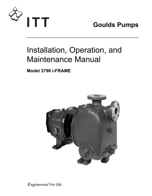
Goulds Pumps<strong>Installation</strong>, <strong>Operation</strong>, <strong>and</strong><strong>Maintenance</strong> <strong>Manual</strong>Model 3796 i-FRAME
Table of ContentsTable of ContentsIntroduction <strong>and</strong> Safety...................................................................................................................................................4Introduction.......................................................................................................................................................................4Requesting other information......................................................................................................................................4Inspect the package........................................................................................................................................................4Inspect the unit...............................................................................................................................................................4Product warranty............................................................................................................................................................4Safety...................................................................................................................................................................................5Safety terminology <strong>and</strong> symbols..................................................................................................................................5Environmental safety.....................................................................................................................................................6User health <strong>and</strong> safety...................................................................................................................................................7Safety regulations for Ex-approved products in potentially explosive atmospheres...........................................8Product approval st<strong>and</strong>ards...........................................................................................................................................10Certificates of conformance..........................................................................................................................................11Transportation <strong>and</strong> Storage..........................................................................................................................................17Pump h<strong>and</strong>ling.................................................................................................................................................................17Lifting methods............................................................................................................................................................17Pump storage requirements...........................................................................................................................................19Frostproofing...................................................................................................................................................................19Product Description........................................................................................................................................................20General description 3796...............................................................................................................................................20Part description 3796...................................................................................................................................................21General description i-ALERT Condition Monitor................................................................................................22Nameplate information..................................................................................................................................................23<strong>Installation</strong>.........................................................................................................................................................................26Preinstallation...................................................................................................................................................................26Pump location guidelines............................................................................................................................................26Foundation requirements............................................................................................................................................27Piping checklists...........................................................................................................................................................28Baseplate-mounting procedures....................................................................................................................................32Prepare the baseplate for mounting..........................................................................................................................32Install the baseplate using shims or wedges.............................................................................................................32Install the baseplate using jackscrews.......................................................................................................................33Install the baseplate using spring mounting.............................................................................................................35Install the baseplate using stilt mounting.................................................................................................................36Baseplate-leveling worksheet......................................................................................................................................38Install the pump, driver, <strong>and</strong> coupling.........................................................................................................................39Pump-to-driver alignment..............................................................................................................................................39Alignment checks.........................................................................................................................................................39Permitted indicator values for alignment checks....................................................................................................40Alignment measurement guidelines..........................................................................................................................40Attach the dial indicators for alignment...................................................................................................................40Pump-to-driver alignment instructions....................................................................................................................41C-face adapter...............................................................................................................................................................44Grout the baseplate.........................................................................................................................................................44Commissioning, Startup, <strong>Operation</strong>, <strong>and</strong> Shutdown............................................................................................46Preparation for startup...................................................................................................................................................46Remove the coupling guard...........................................................................................................................................46Check the rotation...........................................................................................................................................................49Model 3796 i-FRAME <strong>Installation</strong>, <strong>Operation</strong>, <strong>and</strong> <strong>Maintenance</strong> <strong>Manual</strong> 1
Table of ContentsImpeller-clearance check................................................................................................................................................49Impeller clearances (3796)..........................................................................................................................................49Impeller-clearance setting..............................................................................................................................................50Set the impeller clearance - dial indicator method (all except CV 3196) ............................................................50Set the impeller clearance - feeler gauge method (all except CV 3196) .............................................................51Couple the pump <strong>and</strong> driver..........................................................................................................................................51Install the coupling guard...........................................................................................................................................52Bearing lubrication.......................................................................................................................................................56Shaft-sealing options.......................................................................................................................................................58Mechanical seal options..............................................................................................................................................58Connection of sealing liquid for mechanical seals..................................................................................................58Packed stuffing box option.........................................................................................................................................58Connection of sealing liquid for a packed stuffing box.........................................................................................58Pump priming..................................................................................................................................................................59Pump priming with the suction supply below the pump (3796)..........................................................................59Start the pump.................................................................................................................................................................60Activate the i-ALERT Condition Monitor..............................................................................................................60i-ALERT Condition Monitor routine operation....................................................................................................61Pump operation precautions.........................................................................................................................................62Shut down the pump......................................................................................................................................................62Deactivate the i-ALERT Condition Monitor..........................................................................................................63Reset the i-ALERT Condition Monitor...................................................................................................................63Make the final alignment of the pump <strong>and</strong> driver......................................................................................................63<strong>Maintenance</strong>......................................................................................................................................................................64<strong>Maintenance</strong> schedule.....................................................................................................................................................64Bearing maintenance.......................................................................................................................................................65Lubricating-oil requirements......................................................................................................................................65Regrease the grease-lubricated bearings ..................................................................................................................66Lubricate the bearings after a shutdown period......................................................................................................67Shaft seal maintenance...................................................................................................................................................67Mechanical-seal maintenance.....................................................................................................................................67Packed stuffing-box maintenance..............................................................................................................................68Disassembly......................................................................................................................................................................68Disassembly precautions.............................................................................................................................................68Tools required...............................................................................................................................................................68Drain the pump............................................................................................................................................................69Remove the coupling...................................................................................................................................................69Remove the back pull-out assembly..........................................................................................................................69Remove the coupling hub...........................................................................................................................................72Impeller removal..........................................................................................................................................................72Seal-chamber cover removal.......................................................................................................................................73Remove the seal-chamber cover (3196, CV 3196, HT 3196, LF 3196, 3796) ...................................................73Remove the stuffing-box cover (3196, CV 3196, HT 3196, LF 3196, 3796) ....................................................74Remove the frame adapter (MTi, LTi) .....................................................................................................................75Remove the inboard labyrinth oil seal.......................................................................................................................75Power-end disassembly...............................................................................................................................................75Disassemble the bearing frame..................................................................................................................................80Guidelines for i-ALERT Condition Monitor disposal.......................................................................................81Disassemble the C-face adapter.................................................................................................................................81Pre-assembly inspections...............................................................................................................................................82Replacement guidelines...............................................................................................................................................82Shaft <strong>and</strong> sleeve replacement guidelines...................................................................................................................83Bearing-frame inspection............................................................................................................................................83C-face adapter inspection...........................................................................................................................................84Seal chamber <strong>and</strong> stuffing box cover inspection.....................................................................................................85Bearings inspection......................................................................................................................................................862 Model 3796 i-FRAME <strong>Installation</strong>, <strong>Operation</strong>, <strong>and</strong> <strong>Maintenance</strong> <strong>Manual</strong>
Table of ContentsBearing-housing inspection........................................................................................................................................87Bearing fits <strong>and</strong> tolerances..........................................................................................................................................88Reassembly.......................................................................................................................................................................88Assemble the rotating element <strong>and</strong> the bearing frame ( STi <strong>and</strong> MTi ) .............................................................88Assemble the rotating element <strong>and</strong> the bearing frame ( STi <strong>and</strong> MTi with duplex bearings).........................91Assemble the rotating element <strong>and</strong> the bearing frame ( LTi )..............................................................................94Assemble the frame.....................................................................................................................................................97INPRO labyrinth oil seal description.....................................................................................................................100Assemble the INPRO labyrinth oil seal.................................................................................................................100Assemble the C-face adapter....................................................................................................................................101Shaft sealing................................................................................................................................................................101Install the impeller.....................................................................................................................................................106Attach the i-ALERT Condition Monitor to the pump....................................................................................108Post-assembly checks................................................................................................................................................109Install the back pull-out assembly (except HT 3196) ..........................................................................................109Assembly references..................................................................................................................................................111Spare parts...................................................................................................................................................................112Interchangeability drawings.........................................................................................................................................1133796 interchangeability..............................................................................................................................................113Lubrication conversion.................................................................................................................................................113Frame lubrication conversion..................................................................................................................................113Convert from greased-for-life or regreaseable to oil-lubricated bearings.........................................................114Conversion from flood-oil to pure-oil mist...........................................................................................................115Convert from flood oil to regreaseable..................................................................................................................115Troubleshooting.............................................................................................................................................................116<strong>Operation</strong> troubleshooting..........................................................................................................................................116Alignment troubleshooting..........................................................................................................................................117Assembly troubleshooting...........................................................................................................................................117i-ALERT Condition Monitor troubleshooting.....................................................................................................118Parts Listings <strong>and</strong> Cross-Sectional Drawings.......................................................................................................119Parts list..........................................................................................................................................................................119Other Relevant Documentation or <strong>Manual</strong>s.........................................................................................................130For additional documentation.....................................................................................................................................130Model 3796 i-FRAME <strong>Installation</strong>, <strong>Operation</strong>, <strong>and</strong> <strong>Maintenance</strong> <strong>Manual</strong> 3
Introduction <strong>and</strong> SafetyIntroduction <strong>and</strong> SafetyIntroductionPurpose of this manualThe purpose of this manual is to provide necessary information for:• <strong>Installation</strong>• <strong>Operation</strong>• <strong>Maintenance</strong>CAUTION:Read this manual carefully before installing <strong>and</strong> using the product. Improper use of the product can causepersonal injury <strong>and</strong> damage to property, <strong>and</strong> may void the warranty.NOTICE:Save this manual for future reference, <strong>and</strong> keep it readily available at the location of the unit.Requesting other informationSpecial versions can be supplied with supplementary instruction leaflets. See the sales contract for anymodifications or special version characteristics. For instructions, situations, or events that are notconsidered in this manual or in the sales documents, please contact the nearest ITT representative.Always specify the exact product type <strong>and</strong> identification code when requesting technical information orspare parts.Inspect the package1. Inspect the package for damaged or missing items upon delivery.2. Note any damaged or missing items on the receipt <strong>and</strong> freight bill.3. File a claim with the shipping company if anything is out of order.If the product has been picked up at a distributor, make a claim directly to the distributor.Inspect the unit1. Remove packing materials from the product.Product warrantyDispose of all packing materials in accordance with local regulations.2. Inspect the product to determine if any parts have been damaged or are missing.3. If applicable, unfasten the product by removing any screws, bolts, or straps.For your personal safety, be careful when you h<strong>and</strong>le nails <strong>and</strong> straps.4. Contact your sales representative if anything is out of order.CoverageITT undertakes to remedy faults in products from ITT under these conditions:• The faults are due to defects in design, materials, or workmanship.• The faults are reported to an ITT representative within the warranty period.• The product is used only under the conditions described in this manual.• The monitoring equipment incorporated in the product is correctly connected <strong>and</strong> in use.• All service <strong>and</strong> repair work is done by ITT-authorized personnel.• Genuine ITT parts are used.• Only Ex-approved spare parts <strong>and</strong> accessories authorized by ITT are used in Ex-approved products.4 Model 3796 i-FRAME <strong>Installation</strong>, <strong>Operation</strong>, <strong>and</strong> <strong>Maintenance</strong> <strong>Manual</strong>
Introduction <strong>and</strong> Safety (Continued)LimitationsWarranty claimThe warranty does not cover faults caused by these situations:• Deficient maintenance• Improper installation• Modifications or changes to the product <strong>and</strong> installation made without consulting ITT• Incorrectly executed repair work• Normal wear <strong>and</strong> tearITT assumes no liability for these situations:• Bodily injuries• Material damages• Economic lossesITT products are high-quality products with expected reliable operation <strong>and</strong> long life. However, should theneed arise for a warranty claim, then contact your ITT representative.SafetyWARNING:• The operator must be aware of safety precautions to prevent physical injury.• Any pressure-containing device can explode, rupture, or discharge its contents if it is over-pressurized.Take all necessary measures to avoid over-pressurization.• Operating, installing, or maintaining the unit in any way that is not covered in this manual could causedeath, serious personal injury, or damage to the equipment. This includes any modification to theequipment or use of parts not provided by ITT. If there is a question regarding the intended use ofthe equipment, please contact an ITT representative before proceeding.• <strong>Installation</strong>, <strong>Operation</strong>, <strong>and</strong> <strong>Maintenance</strong> manuals clearly identify accepted methods for disassemblingunits. These methods must be adhered to. Trapped liquid can rapidly exp<strong>and</strong> <strong>and</strong> result in a violentexplosion <strong>and</strong> injury. Never apply heat to impellers, propellers, or their retaining devices to aid in theirremoval.• Do not change the service application without the approval of an authorized ITT representative.• Never operate the pump below the minimum rated flow, when dry, or without prime.• Never operate the pump without safety devices installed.• Never operate the pump with the discharge valve closed.• Never operate the pump with the suction valve closed.Safety terminology <strong>and</strong> symbolsAbout safety messagesIt is extremely important that you read, underst<strong>and</strong>, <strong>and</strong> follow the safety messages <strong>and</strong> regulationscarefully before h<strong>and</strong>ling the product. They are published to help prevent these hazards:• Personal accidents <strong>and</strong> health problems• Damage to the product• Product malfunctionModel 3796 i-FRAME <strong>Installation</strong>, <strong>Operation</strong>, <strong>and</strong> <strong>Maintenance</strong> <strong>Manual</strong> 5
Introduction <strong>and</strong> Safety (Continued)Hazard levelsHazard levelDANGER:IndicationA hazardous situation which, if not avoided, willresult in death or serious injuryWARNING:A hazardous situation which, if not avoided, couldresult in death or serious injuryCAUTION:A hazardous situation which, if not avoided, couldresult in minor or moderate injuryNOTICE:• A potential situation which, if not avoided,could result in undesirable conditions• A practice not related to personal injuryHazard categoriesHazard categories can either fall under hazard levels or let specific symbols replace the ordinary hazardlevel symbols.Electrical hazards are indicated by the following specific symbol:Electrical Hazard:Environmental safetyThese are examples of other categories that can occur. They fall under the ordinary hazard levels <strong>and</strong> mayuse complementing symbols:• Crush hazard• Cutting hazard• Arc flash hazardThe work areaAlways keep the pump station clean to avoid <strong>and</strong>/or discover emissions.Recycling guidelinesWaste <strong>and</strong> emissions regulationsAlways recycle according to these guidelines:1. If the unit or parts are accepted by an authorized recycling company, then follow local recycling laws<strong>and</strong> regulations.2. If the unit or parts are not accepted by an authorized recycling company, then return them to thenearest ITT representative.Observe these safety regulations regarding waste <strong>and</strong> emissions:• Dispose appropriately of all waste.• H<strong>and</strong>le <strong>and</strong> dispose of the pumped fluid in compliance with applicable environmental regulations.• Clean up all spills in accordance with safety <strong>and</strong> environmental procedures.• Report all environmental emissions to the appropriate authorities.6 Model 3796 i-FRAME <strong>Installation</strong>, <strong>Operation</strong>, <strong>and</strong> <strong>Maintenance</strong> <strong>Manual</strong>
Introduction <strong>and</strong> Safety (Continued)Reference for electrical installationFor electrical installation requirements, consult your local electric utility.User health <strong>and</strong> safetySafety equipmentThe work areaUse safety equipment according to the company regulations. Use this safety equipment within the workarea:• Helmet• Safety goggles (with side shields)• Protective shoes• Protective gloves• Gas mask• Hearing protectionObserve these regulations <strong>and</strong> warnings in the work area:• Always keep the work area clean.• Pay attention to the risks presented by gas <strong>and</strong> vapors in the work area.• Avoid all electrical dangers. Pay attention to the risks of electric shock or arc flash hazards.Product <strong>and</strong> product positioning requirementsElectrical connections regulationsEarthing (grounding)Observe these requirements for the product <strong>and</strong> the product positioning:WARNING:• Only use fasteners of the proper size <strong>and</strong> material.• Replace all corroded fasteners.• Make sure that all fasteners are properly tightened <strong>and</strong> that there are no missing fasteners.• Never operate a pump unless safety devices are installed.• Never operate a pump unless a coupling guard is installed.• Never force the piping in order to make a connection with a pump.• Never start a pump without the proper priming.• Never start a pump without the proper liquid level in self-priming pumps.• Never run a pump below the minimum rated flow or with any suction or discharge valve closed.Electrical connections must be made by certified electricians in compliance with all international, national,state, <strong>and</strong> local regulations.Observe these guidelines <strong>and</strong> warnings for electrical connections:• Make sure that the product is isolated from the power supply <strong>and</strong> cannot be energized by mistake.This guideline also applies to the control circuit.• Make sure that the thermal contacts are connected to a protection circuit according to the productapprovals, <strong>and</strong> that they are in use.All electric equipment must be earthed (grounded). This rule applies to pumps <strong>and</strong> mixers as well asmonitoring equipment.Precautions before workObserve these safety precautions before you work with the product or are in connection with the product:• Provide a suitable barrier around the work area, for example, a guard rail.• Make sure that all safety guards are in place <strong>and</strong> secure.• Make sure that the equipment is properly insulated when it operates at extreme temperatures.• Allow all system <strong>and</strong> pump components to cool before you h<strong>and</strong>le them.Model 3796 i-FRAME <strong>Installation</strong>, <strong>Operation</strong>, <strong>and</strong> <strong>Maintenance</strong> <strong>Manual</strong> 7
Introduction <strong>and</strong> Safety (Continued)Precautions during work• Make sure that you have a clear path of retreat.• Make sure that the product cannot roll or fall over <strong>and</strong> injure people or damage property.• Make sure that the lifting equipment is in good condition.• Use a lifting harness, a safety line, <strong>and</strong> a breathing device as required.• Make sure that the product is thoroughly clean.• Make sure that there are no poisonous gases within the work area.• Make sure that you have quick access to a first-aid kit.• Disconnect <strong>and</strong> lock out power before servicing.• Check the explosion risk before you weld or use electric h<strong>and</strong> tools.Observe these safety precautions when you work with the product or are in connection with the product:• Never work alone.• Always wear protective clothing <strong>and</strong> h<strong>and</strong> protection.• Stay clear of suspended loads.• Always lift the product by its lifting device.• Beware of the risk of a sudden start if the product is used with an automatic level control.• Beware of the starting jerk, which can be powerful.• Rinse the components in water after you disassemble the pump.• Do not exceed the maximum working pressure of the pump.• Do not open any vent or drain valve or remove any plugs while the system is pressurized. Make surethat the pump is isolated from the system <strong>and</strong> that pressure is relieved before you disassemble thepump, remove plugs, or disconnect piping.• Never operate a pump without a properly installed coupling guard.• Always bear in mind the risk of drowning, electrical accidents, <strong>and</strong> burn injuries.• Never heat the condition monitor to temperatures in excess of 300°F (149°C).• Never expose the condition monitor to open flames.• Do not use the condition monitor in atmospheres containing acetic acid.• Always wear protective gloves. The pump <strong>and</strong> condition monitor can be hot.Clean chemicals from the eyes1. Hold your eyelids apart forcibly with your fingers.2. Rinse the eyes for at least 15 minutes.Use an eyewash or running water.3. Seek medical attention.Clean chemicals from the body1. Remove contaminated clothing.2. Wash the skin with soap <strong>and</strong> water for at least one minute.3. Seek medical attention, if required.Safety regulations for Ex-approved products in potentially explosiveatmospheresDescription of ATEXThe ATEX directives are a specification enforced in Europe for electrical <strong>and</strong> non-electrical equipment.ATEX deals with the control of potentially explosive atmospheres <strong>and</strong> the st<strong>and</strong>ards of equipment <strong>and</strong>protective systems used within these atmospheres. The relevance of the ATEX requirements is not limitedto Europe. You can apply these guidelines to equipment installed in any potentially explosive atmosphere.8 Model 3796 i-FRAME <strong>Installation</strong>, <strong>Operation</strong>, <strong>and</strong> <strong>Maintenance</strong> <strong>Manual</strong>
Introduction <strong>and</strong> Safety (Continued)General guidelinesATEX compliance is only fulfilled when the pump is operated within its intended use, for example withinits intended hydraulic range. The conditions of the service must not be changed without approval of anauthorized ITT representative. When installing or maintaining ATEX-compliant pumps, follow theseguidelines:• Always install ATEX-approved equipment in compliance with the directive <strong>and</strong> applicable st<strong>and</strong>ards(IEC/EN 60079–14).• Do not install FM-approved products in locations that are classified as hazardous in the nationalelectric code, ANSI/NFPA 70–2005.Personnel requirementsWARNING:<strong>Installation</strong>, <strong>Operation</strong>, <strong>and</strong> <strong>Maintenance</strong> manuals clearly identify accepted methods for disassemblingunits. These methods must be adhered to. Trapped liquid can rapidly exp<strong>and</strong> <strong>and</strong> result in a violentexplosion <strong>and</strong> injury. Never apply heat to impellers, propellers, or their retaining devices to aid in theirremoval.If there are any questions regarding these requirements, the intended use, or if the equipment requiresmodification, contact an ITT representative before you proceed.ITT disclaims all responsibility for work done by untrained <strong>and</strong> unauthorized personnel.These are the personnel requirements for Ex-approved products in potentially explosive atmospheres:Product <strong>and</strong> product h<strong>and</strong>ling requirements• All work on the product must be carried out by certified electricians <strong>and</strong> ITT-authorized mechanics.Special rules apply to installations in explosive atmospheres.• All users must know about the risks of electric current <strong>and</strong> the chemical <strong>and</strong> physical characteristics ofthe gas <strong>and</strong>/or vapor present in hazardous areas.• The maintenance operation for Ex-approved products must be made in conformity to theinternational or national st<strong>and</strong>ards (IEC/EN 60079-17).These are the product <strong>and</strong> product h<strong>and</strong>ling requirements for Ex-approved products in potentiallyexplosive atmospheres:• Only use the product in accordance with the approved motor data stated on the nameplates.• The Ex-approved product must never run dry during normal operation. Dry running during service<strong>and</strong> inspection is only permitted outside the classified area.• Never start a pump without the proper priming.• Before you start working with the product, make sure that the product <strong>and</strong> the control panel areisolated from the power supply <strong>and</strong> the control circuit, so they cannot be energized.• Do not open the product while it is energized or in an explosive gas atmosphere.• Make sure that thermal contacts are connected to a protection circuit according to the approvalclassification of the product.• Intrinsically safe circuits are normally required for the automatic level-control system by the levelregulator if mounted in zone 0.• The yield stress of fasteners must be in accordance with the approval drawing <strong>and</strong> the productspecification.• Make sure that the equipment is properly maintained:• Monitor the pump components <strong>and</strong> the end temperature of the liquid.• Maintain proper bearing lubrication.• Do not modify the equipment without approval from an authorized ITT representative.• Only use parts that have been provided by an authorized ITT representative.Model 3796 i-FRAME <strong>Installation</strong>, <strong>Operation</strong>, <strong>and</strong> <strong>Maintenance</strong> <strong>Manual</strong> 9
Introduction <strong>and</strong> Safety (Continued)Equipment for monitoringFor additional safety, use condition-monitoring devices. Condition-monitoring devices include but are notlimited to these devices:• Pressure gauges• Flow meters• Level indicators• Motor load readings• Temperature detectors• Bearing monitors• Leak detectors• PumpSmart control systemProduct approval st<strong>and</strong>ardsRegular st<strong>and</strong>ardsAll st<strong>and</strong>ard products are approved according to CSA st<strong>and</strong>ards in Canada <strong>and</strong> UL st<strong>and</strong>ards in USA. Thedrive unit degree of protection follows IP68. See the nameplate for maximum submersion, according tost<strong>and</strong>ard IEC 60529.All electrical ratings <strong>and</strong> performance of the motors comply with IEC 600341.Explosion-proofing st<strong>and</strong>ardsAll explosion-proof products for use in explosive atmospheres are designed in compliance with one ormore of the following approvals:• EN, ATEX Directive 94/9/EC• FM According to NEC• Class 1 Div 1 Groups “C”, <strong>and</strong> “D”• Class 2 Div 1 Groups “E”, “F”, <strong>and</strong> “G”• Class 3 Div 1 Hazardous LocationsATEX/IECEx:• Group: IIC• Category: Ex ia• Temperature Class: T4 (for ambients up to 100ºC)• ATEX Marking: Ex II 1 G2D Barcode HereCSA certificationIntrinsically safe for:• Class I, Div. 1, Groups A, B, C, D• Class II, Div. 1, Groups E, F, G• Class III• Certified to Canadian <strong>and</strong> US requirementsSERIAL NO. & YEAR OFMANUFACTURE HERE.10 Model 3796 i-FRAME <strong>Installation</strong>, <strong>Operation</strong>, <strong>and</strong> <strong>Maintenance</strong> <strong>Manual</strong>
Introduction <strong>and</strong> Safety (Continued)Certificates of conformanceCSA CertificateModel 3796 i-FRAME <strong>Installation</strong>, <strong>Operation</strong>, <strong>and</strong> <strong>Maintenance</strong> <strong>Manual</strong> 11
Introduction <strong>and</strong> Safety (Continued)12 Model 3796 i-FRAME <strong>Installation</strong>, <strong>Operation</strong>, <strong>and</strong> <strong>Maintenance</strong> <strong>Manual</strong>
Introduction <strong>and</strong> Safety (Continued)ATEX notificationModel 3796 i-FRAME <strong>Installation</strong>, <strong>Operation</strong>, <strong>and</strong> <strong>Maintenance</strong> <strong>Manual</strong> 13
Introduction <strong>and</strong> Safety (Continued)IECEx Certificate of Conformity14 Model 3796 i-FRAME <strong>Installation</strong>, <strong>Operation</strong>, <strong>and</strong> <strong>Maintenance</strong> <strong>Manual</strong>
Introduction <strong>and</strong> Safety (Continued)Model 3796 i-FRAME <strong>Installation</strong>, <strong>Operation</strong>, <strong>and</strong> <strong>Maintenance</strong> <strong>Manual</strong> 15
Introduction <strong>and</strong> Safety (Continued)Chinese Certificate of Conformity16 Model 3796 i-FRAME <strong>Installation</strong>, <strong>Operation</strong>, <strong>and</strong> <strong>Maintenance</strong> <strong>Manual</strong>
Transportation <strong>and</strong> StorageTransportation <strong>and</strong> StoragePump h<strong>and</strong>lingWARNING:• Make sure that the pump cannot roll or fall over <strong>and</strong> injure people or damage property.• These pumps might use carbon or ceramic silicon carbide components. Do not drop the pump orsubject it to shock loads as this can damage the internal ceramic components.Lifting methodsNOTICE: Use a forklift truck or an overhead crane with sufficient capacity to move the pallet with thepump unit on top. Failure to do so can result in equipment damage.WARNING:• Assembled units <strong>and</strong> their components are heavy. Failure to properly lift <strong>and</strong> support this equipmentcan result in serious physical injury <strong>and</strong>/or equipment damage. Lift equipment only at the specificallyidentified lifting points. Lifting devices such as eyebolts, slings, <strong>and</strong> spreaders must be rated, selected,<strong>and</strong> used for the entire load being lifted.• Crush hazard. The unit <strong>and</strong> the components can be heavy. Use proper lifting methods <strong>and</strong> wear steeltoedshoes at all times.• Do not attach sling ropes to shaft ends.ExamplesTable 1: MethodsPump typeA bare pump without liftingh<strong>and</strong>lesLifting methodA bare pump with lifting h<strong>and</strong>les Lift the pump by the h<strong>and</strong>les.A base-mounted pumpMounted on top of a PolyshieldANSI ComboUse a suitable sling attached properly to solid points like the casing, theflanges, or the frames.Use slings under the pump casing <strong>and</strong> the drive unit, or under the baserails.See separate information regarding the Polyshield ANSI Combo.Figure 1: Example of a proper lifting methodModel 3796 i-FRAME <strong>Installation</strong>, <strong>Operation</strong>, <strong>and</strong> <strong>Maintenance</strong> <strong>Manual</strong> 17
Transportation <strong>and</strong> Storage (Continued)NOTICE: Do not use this lifting method to lift a Polyshield ANSI Combo with the pump <strong>and</strong> motormounted. Doing so may result in equipment damage.Figure 2: Example of a proper lifting methodNOTICE: Do not use this lifting method to lift a Polyshield ANSI Combo with the pump <strong>and</strong> motormounted. Doing so may result in equipment damage.Figure 3: Example of a proper lifting methodNOTICE: When lifting a unit that does not have a way to secure the strap on the suction flange, you mustsecure the strap around the frame adapter. Failure to do so may result in equipment damage.Figure 4: Example of a proper lifting method with a strap secured around the frame adapter18 Model 3796 i-FRAME <strong>Installation</strong>, <strong>Operation</strong>, <strong>and</strong> <strong>Maintenance</strong> <strong>Manual</strong>
Transportation <strong>and</strong> Storage (Continued)Pump storage requirementsStorage requirements depend on the amount of time that you store the pump. The normal packaging isdesigned only to protect the pump during shipping.Length of time in storageUpon receipt/short-term (less than six months)Long-term (more than six months)Storage requirements• Store in a covered <strong>and</strong> dry location.• Store the unit free from dirt <strong>and</strong> vibrations.• Store in a covered <strong>and</strong> dry location.• Store the unit free from heat, dirt, <strong>and</strong>vibrations.• Rotate the shaft by h<strong>and</strong> several times at leastevery three months.Treat bearing <strong>and</strong> machined surfaces so that they are well preserved. Refer to drive unit <strong>and</strong> couplingmanufacturers for their long-term storage procedures.FrostproofingTable 2: Situations when the pump is or is not frostproofWhen the pump is...Then...OperatingImmersed in a liquidLifted out of a liquid into a temperature belowfreezingThe pump is frostproof.The pump is frostproof.The impeller might freeze.Model 3796 i-FRAME <strong>Installation</strong>, <strong>Operation</strong>, <strong>and</strong> <strong>Maintenance</strong> <strong>Manual</strong> 19
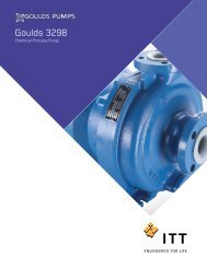
Product DescriptionProduct DescriptionGeneral description 3796The 3796 is a horizontal overhung, self-priming, open impeller, centrifugal pump.This model is based on 3 power ends <strong>and</strong> 8 hydraulic pump sizes.Figure 5: 3796 pumpThis table shows the number of hydraulic sizes available for each drive-unit size group.Pump size groupNumber of hydraulic sizesSTi 2MTi 6LTi 620 Model 3796 i-FRAME <strong>Installation</strong>, <strong>Operation</strong>, <strong>and</strong> <strong>Maintenance</strong> <strong>Manual</strong>
Product Description (Continued)Part description 3796Casing Impeller Cover Power end31963796HT 3196CV 3196LF 3196NM 31963198Figure 6: 3796 part descriptionThis table describes the pump casing parts.Table 3: CasingPartDischargeCasing ventilationPriming chamberGasketMounting methodSt<strong>and</strong>ard flangeOptional heaterDescriptionTop-centerlineSelf-ventingintegrally cast allowing the pump to evacuate air to prime itselffully confinedIntegral foot support for maximum resistance to misalignment <strong>and</strong> distortion dueto piping loadsANSI class 150 raised-face serrated flangeImmersion heater to prevent the liquid in the priming chamber from freezing inoutdoor applicationsImpellerThe impeller is• fully open• screwed onto the shaftThe threads are sealed from the pumped liquid by a Teflon O-ring.Model 3796 i-FRAME <strong>Installation</strong>, <strong>Operation</strong>, <strong>and</strong> <strong>Maintenance</strong> <strong>Manual</strong> 21
Product Description (Continued)CoverSt<strong>and</strong>ard seal• The 3796 is available with a stuffing-box cover designed for a packing <strong>and</strong> a BigBore or a TaperBorePLUS seal chamber.Optional seal• a dynamic seal is available which uses a repeller to pump liquid out of the stuffing box while the pumpoperates. A static seal prevents leakage when the pump is shut down.This table describes the main parts of the power end.Table 4: Power endPartFrame adapterPower endShaftBearingsDescriptionThe ductile iron frame adapter has• a machined rabbet fitted to the seal chamber/ stuffing box cover• a precision dowel pin fitted to the bearing frame.• Flood-oil lubrication is st<strong>and</strong>ard.• No machining is required to convert from oil to grease or oil-mist lubrication.Regreasable bearings <strong>and</strong> oil-mist lubrication are optional.• The oil level is checked through a sight glass.• The power end is sealed with labyrinth seals.• The power end is made in the following sizes:• STi• MTi• LTiThe shaft is available with or without a sleeve.The inboard bearing• carries only radial loads.• is free to float axially in the frame.• is a single-row deep-groove ball bearingThe outboard bearing• is shouldered <strong>and</strong> locked to the shaft <strong>and</strong> housing to enable it to carry radial<strong>and</strong> thrust loads.• is a double-row angular-contact bearing, except for the LTi which uses a pair ofsingle-row angular-contact ball bearings mounted back-to-back.General description i-ALERT Condition MonitorDescriptionAlarm modeThe i-ALERT Condition Monitor is a compact, battery-operated monitoring device that continuouslymeasures the vibration <strong>and</strong> temperature of the pump power end. The condition monitor uses blinking redLEDs to alert the pump operator when the pump exceeds pre-set vibration <strong>and</strong> temperature limits. Thisallows the pump operator to make changes to the process or the pump before a catastrophic failureoccurs. The condition monitor is also equipped with a single green LED to indicate when it is operational<strong>and</strong> has sufficient battery life.The condition monitor enters alarm mode when either vibration or temperature limits are exceeded overtwo consecutive readings within a ten minute period. Alarm mode is indicated with two red flashing LEDswithin two second intervals.Temperature <strong>and</strong> vibration limitsVariableTemperatureLimit195°F (91°C)22 Model 3796 i-FRAME <strong>Installation</strong>, <strong>Operation</strong>, <strong>and</strong> <strong>Maintenance</strong> <strong>Manual</strong>
Product Description (Continued)VariableVibrationLimit100% increase over the baseline levelBattery lifeThe i-ALERT Condition Monitor battery is not replaceable. You must replace the entire unit oncethe battery runs out of power.The battery life is not covered as part of the st<strong>and</strong>ard five-year pump warranty.This table shows the average condition monitor battery life under normal <strong>and</strong> alarm-mode operatingconditions.Condition monitor operational stateBattery lifeNormal operating <strong>and</strong> environmental conditionsAlarm modeThree to five yearsOne yearNameplate informationImportant information for orderingNameplate typesEvery pump has nameplates that provide information about the pump. The nameplates are located on thecasing <strong>and</strong> the bearing frame.When you order spare parts, identify this pump information:• Model• Size• Serial number• Item numbers of the required partsRefer to the nameplate on the pump casing for most of the information. See Parts List for item numbers.NameplatePump casingBearing frameATEXIECExDescriptionNameplate on the pump casing using English unitsProvides information about the hydraulic characteristics of the pump.The formula for the pump size is: Discharge x Suction - Nominal Maximum ImpellerDiameter in inches.(Example: 2x3-8)Provides information about the lubrication system used.If applicable, your pump unit might have an ATEX nameplate affixed to the pump, thebaseplate, or the discharge head. The nameplate provides information about the ATEXspecifications of this pump.If applicable, your pump unit might have the following IECEx nameplate affixed to thepump <strong>and</strong>/or baseplate. The nameplate provides information about the IECExspecifications of this pump.Model 3796 i-FRAME <strong>Installation</strong>, <strong>Operation</strong>, <strong>and</strong> <strong>Maintenance</strong> <strong>Manual</strong> 23
Product Description (Continued)Table 5: Explanation of nameplate on the pump casingNameplate field ExplanationIMPLR. DIA.MAX. DIA.GPMFT HDRPMMOD.SIZESTD. NO.Impeller diameter, in inchesMaximum impeller diameter, in inchesRated pump flow, in gallons per minuteRated pump head, in feetRated pump speed, revolutions per minutePump modelSize of the pumpANSI st<strong>and</strong>ard designationMAT L. CONST. Material of which the pump is constructedSER. NO.MAX DSGN PSI@ 100FSerial number of the pumpMaximum pressure at 100ºF according to the pump designNameplate on the pump casing using metric unitsTable 6: Explanation of the nameplate on the pump casingNameplate field ExplanationIMPLR. DIA.MAX. DIA.M 3 /HRM HDRPMMOD.SIZESTD. NO.MAT L. CONSTSER. NO.MAX. DSGN KG/CM 3 @20°CImpeller diameterMaximum impeller diameterRated pump flow, in cubic meters per hourRated pump head, in metersRated pump speed, in revolutions per minutePump modelSize of the pumpANSI st<strong>and</strong>ard designationMaterial of which the pump is constructedSerial number of the pumpKilograms per cubic centimeter at 20°C24 Model 3796 i-FRAME <strong>Installation</strong>, <strong>Operation</strong>, <strong>and</strong> <strong>Maintenance</strong> <strong>Manual</strong>
Product Description (Continued)Nameplate on the bearing frameATEX nameplateTable 7: Explanation of the nameplate on the bearing frameNameplate field ExplanationMOD.SIZESER. NO.LUBEPump modelSize of the pumpSerial number of the pumpLubricant, oil or greaseNameplate fieldExplanationII Group 22 Category 2G/DPump can be used when gas <strong>and</strong> dust are presentT4Temperature classNOTICE: Make sure that the code classifications on the pump are compatible with the specificenvironment in which you plan to install the equipment. If they are not compatible, do not operate theequipment <strong>and</strong> contact your ITT representative before you proceed.Model 3796 i-FRAME <strong>Installation</strong>, <strong>Operation</strong>, <strong>and</strong> <strong>Maintenance</strong> <strong>Manual</strong> 25
<strong>Installation</strong><strong>Installation</strong>PreinstallationPrecautionsWARNING:• When installing in a potentially explosive environment, make sure that the motor is properly certified.• You must earth (ground) all electrical equipment. This applies to the pump equipment, the driver, <strong>and</strong>any monitoring equipment. Test the earth (ground) lead to verify that it is connected correctly.Pump location guidelinesNOTICE: Supervision by an authorized ITT representative is recommended to ensure proper installation.Failure to do so may result in equipment damage or decreased performance.WARNING:Assembled units <strong>and</strong> their components are heavy. Failure to properly lift <strong>and</strong> support this equipment canresult in serious physical injury <strong>and</strong>/or equipment damage. Lift equipment only at the specifically identifiedlifting points. Lifting devices such as eyebolts, slings, <strong>and</strong> spreaders must be rated, selected, <strong>and</strong> used forthe entire load being lifted.GuidelineKeep the pump as close to the liquid source aspractically possible.Make sure that the space around the pump issufficient.If you require lifting equipment such as a hoist ortackle, make sure that there is enough space abovethe pump.Protect the unit from weather <strong>and</strong> water damagedue to rain, flooding, <strong>and</strong> freezing temperatures.Do not install <strong>and</strong> operate the equipment in closedsystems unless the system is constructed withproperly-sized safety devices <strong>and</strong> control devices.Explanation/commentThis minimizes the friction loss <strong>and</strong> keeps thesuction piping as short as possible.This facilitates ventilation, inspection, maintenance,<strong>and</strong> service.This makes it easier to properly use the liftingequipment.This is applicable if nothing else is specified.Acceptable devices:• Pressure relief valves• Compression tanks• Pressure controls• Temperature controls• Flow controlsIf the system does not include these devices, consultthe engineer or architect in charge before youoperate the pump.Take into consideration the occurrence of unwanted The best pump location for noise <strong>and</strong> vibrationnoise <strong>and</strong> vibration.absorption is on a concrete floor with subsoilunderneath.If the pump location is overhead, undertake specialprecautions to reduce possible noise transmission.Consider a consultation with a noise specialist.26 Model 3796 i-FRAME <strong>Installation</strong>, <strong>Operation</strong>, <strong>and</strong> <strong>Maintenance</strong> <strong>Manual</strong>
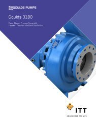
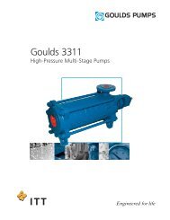
<strong>Installation</strong> (Continued)Foundation requirementsRequirementsSleeve-type bolts• The foundation must be able to absorb any type of vibration <strong>and</strong> form a permanent, rigid support forthe pump unit.• The location <strong>and</strong> size of the foundation bolt holes must match those shown on the assembly drawingprovided with the pump data package.• The foundation must weigh between two <strong>and</strong> three times the weight of the pump.• Provide a flat, substantial concrete foundation in order to prevent strain <strong>and</strong> distortion when youtighten the foundation bolts.• Sleeve-type <strong>and</strong> J-type foundation bolts are most commonly used. Both designs allow movement forthe final bolt adjustment.156234J-type bolts1. Baseplate2. Shims or wedges3. Foundation4. Sleeve5. Dam6. Bolt154231. Baseplate2. Shims or wedges3. Foundation4. Dam5. BoltModel 3796 i-FRAME <strong>Installation</strong>, <strong>Operation</strong>, <strong>and</strong> <strong>Maintenance</strong> <strong>Manual</strong> 27
<strong>Installation</strong> (Continued)Piping checklistsGeneral piping checklistPrecautionsCAUTION:• Never draw piping into place by using force at the flanged connections of the pump. This can imposedangerous strains on the unit <strong>and</strong> cause misalignment between the pump <strong>and</strong> driver. Pipe strainadversely affects the operation of the pump, which results in physical injury <strong>and</strong> damage to theequipment.• Vary the capacity with the regulating valve in the discharge line. Never throttle the flow from thesuction side. This action can result in decreased performance, unexpected heat generation, <strong>and</strong>equipment damage.Piping guidelinesGuidelines for piping are given in the Hydraulic Institute St<strong>and</strong>ards available from the Hydraulic Instituteat 9 Sylvan Way, Parsippany, NJ 07054-3802. You must review this document before you install the pump.ChecklistCheck Explanation/comment CheckedCheck that all piping is supportedindependently of, <strong>and</strong> lined upnaturally with, the pump flange.Keep the piping as short aspossible.Check that only necessary fittingsare used.Do not connect the piping to thepump until:• The grout for the baseplate orsub-base becomes hard.• The hold-down bolts for thepump <strong>and</strong> the driver aretightened.Make sure that all the pipingjoints <strong>and</strong> fittings are airtight.If the pump h<strong>and</strong>les corrosivefluids, make sure that the pipingallows you to flush out the liquidbefore you remove the pump.If the pump h<strong>and</strong>les liquids atelevated temperatures, make surethat the expansion loops <strong>and</strong>joints are properly installed.This helps to prevent:• Strain on the pump• Misalignment between the pump <strong>and</strong> the drive unit• Wear on the pump bearings <strong>and</strong> the coupling• Wear on the pump bearings, seal, <strong>and</strong> shaftingThis helps to minimize friction losses.This helps to minimize friction losses.—This prevents air from entering the piping system orleaks that occur during operation.—This helps to prevent misalignment due to linearexpansion of the piping.28 Model 3796 i-FRAME <strong>Installation</strong>, <strong>Operation</strong>, <strong>and</strong> <strong>Maintenance</strong> <strong>Manual</strong>
<strong>Installation</strong> (Continued)Example: <strong>Installation</strong> for expansionCorrectIncorrect11. Expansion loop/jointSuction-piping checklistPerformance curve referenceSuction-piping checksCheck Explanation/comment CheckedCheck that the distance between the inlet flange ofthe pump <strong>and</strong> the closest elbow is at least five pipediameters.Check that elbows in general do not have sharpbends.Check that the suction piping is one or two sizeslarger than the suction inlet of the pump.Install an eccentric reducer between the pump inlet<strong>and</strong> the suction piping.Check that the eccentric reducer at the suction flangeof the pump has the following properties:• Sloping side down• Horizontal side at the topIf suction strainers or suction bells are used, checkthat they are at least three times the area of thesuction piping.If more than one pump operates from the sameliquid source, check that separate suction-piping linesare used for each pump.If necessary, make sure that the suction pipingincludes a drain valve <strong>and</strong> that it is correctly installed.This minimizes the risk of cavitation inthe suction inlet of the pump due toturbulence.See the Example sections forillustrations.See the Example sections forillustrations.The suction piping must never have asmaller diameter than the suction inlet ofthe pump.See the Example sections forillustrations.See the example illustrations.Suction strainers help to preventclogging.Mesh holes with a minimum diameter of1/16 in. (1.6 mm) are recommended.This recommendation helps you toachieve a higher pump performance.—Model 3796 i-FRAME <strong>Installation</strong>, <strong>Operation</strong>, <strong>and</strong> <strong>Maintenance</strong> <strong>Manual</strong> 29
<strong>Installation</strong> (Continued)Liquid source below the pumpCheck Explanation/comment CheckedMake sure that the suction piping is free fromair pockets.This helps to prevent the occurrence of air<strong>and</strong> cavitation in the pump inlet.Check that the suction piping slopes upwardsfrom the liquid source to the pump inlet.If the pump is not self-priming, check that adevice for priming the pump is installed.—Use a foot valve with a diameter that is at leastequivalent to the diameter of the suctionpiping.Liquid source above the pumpCheck Explanation/comment CheckedCheck that an isolation valve is installed in the This permits you to close the line duringsuction piping at a distance of at least two times pump inspection <strong>and</strong> maintenance.the pipe diameter from the suction inlet. Do not use the isolation valve to throttle thepump. Throttling can cause these problems:• Loss of priming• Excessive temperatures• Damage to the pump• Voiding the warrantyMake sure that the suction piping is free fromair pockets.Check that the piping is level or slopesdownward from the liquid source.Make sure that no part of the suction pipingextends below the suction flange of the pump.Make sure that the suction piping is adequatelysubmerged below the surface of the liquidsource.Example: Elbow close to the pump suction inletThis helps to prevent the occurrence of air<strong>and</strong> cavitation in the pump inlet.——This prevents air from entering the pumpthrough a suction vortex.CorrectThe correct distance between the inlet flange of the pump <strong>and</strong>the closest elbow must be at least five pipe diameters.Incorrect121. Enough distance to prevent cavitation2. Eccentric reducer with a level top30 Model 3796 i-FRAME <strong>Installation</strong>, <strong>Operation</strong>, <strong>and</strong> <strong>Maintenance</strong> <strong>Manual</strong>
<strong>Installation</strong> (Continued)Example: Suction piping equipmentCorrectIncorrect112541. Suction pipe sloping upwards from liquid source2. Long-radius elbow3. Strainer4. Foot valve5. Eccentric reducer with a level top31. Air pocket, because the eccentric reducer is notused <strong>and</strong> because the suction piping does not slopegradually upward from the liquid sourceDischarge piping checklistChecklistCheck Explanation/comment CheckedCheck that an isolation valve isinstalled in the discharge line.Check that a check valve is installed inthe discharge line, between theisolation valve <strong>and</strong> the pump dischargeoutlet.The isolation valve is required for:• Priming• Regulation of flow• Inspection <strong>and</strong> maintenance of the pumpSee Example: Discharge piping equipment forillustrations.The location between the isolation valve <strong>and</strong> thepump allows inspection of the check valve.The check valve prevents damage to the pump <strong>and</strong>seal due to the back flow through the pump, whenthe drive unit is shut off. It is also used to restrainthe liquid flow.See Example: Discharge piping equipment forillustrations.If increasers are used, check that they See Example: Discharge piping equipment forare installed between the pump <strong>and</strong> the illustrations.check valve.If quick-closing valves are installed inthe system, check that cushioningdevices are used.This protects the pump from surges <strong>and</strong> waterhammer.Model 3796 i-FRAME <strong>Installation</strong>, <strong>Operation</strong>, <strong>and</strong> <strong>Maintenance</strong> <strong>Manual</strong> 31
<strong>Installation</strong> (Continued)Example: Discharge piping equipmentCorrectIncorrect4312211. Bypass line2. Shut-off valve3. Check valve4. Discharge isolation valve1. Check valve (incorrect position)2. The isolation valve should not be positionedbetween the check valve <strong>and</strong> the pump.Baseplate-mounting proceduresPrepare the baseplate for mounting1. Remove all the attached equipment from the baseplate.2. Clean the underside of the baseplate completely.3. If applicable, coat the underside of the baseplate with an epoxy primer.Use an epoxy primer only if you used an epoxy-based grout.4. Remove the rust-proofing coat from the machined mounting pads using an appropriate solvent.5. Remove water <strong>and</strong> debris from the foundation-bolt holes.Install the baseplate using shims or wedgesRequired tools:• Two sets of shims or wedges for each foundation bolt• Two machinist's levels• Baseplate-leveling worksheetThis procedure is applicable to cast iron <strong>and</strong> fabricated steel baseplates.1. If you use sleeve-type bolts, fill the bolt sleeves with packing material or rags to prevent grout fromentering the bolt holes.2. Put the sets of wedges or shims on each side of each foundation bolt.The sets of wedges should have a height of between 0.75 in. (19 mm) <strong>and</strong> 1.50 in. (38 mm).32 Model 3796 i-FRAME <strong>Installation</strong>, <strong>Operation</strong>, <strong>and</strong> <strong>Maintenance</strong> <strong>Manual</strong>
<strong>Installation</strong> (Continued)11. Shims or wedgesFigure 7: Top view11. Shims or wedgesFigure 8: Side view3. Lower the baseplate carefully onto the foundation bolts.4. Put the machinist's levels across the mounting pads of the driver <strong>and</strong> the mounting pads of the pump.NOTICE: Remove all dirt from the mounting pads in order to make sure that you achieve thecorrect leveling. Failure to do so can result in equipment damage or decreased performance.5. Level the baseplate both lengthwise <strong>and</strong> across by adding or removing shims or moving the wedges.These are the leveling tolerances:• A maximum difference of 0.125 in. (3.2 mm) lengthwise• A maximum difference of 0.059 in. (1.5 mm) acrossYou can use the baseplate-leveling worksheet when you take the readings.6. H<strong>and</strong>-tighten the nuts for the foundation.Install the baseplate using jackscrewsTools required:• Anti-seize compound• Jackscrews• Bar stock• Two machinist's levels• Baseplate-leveling worksheetThis procedure is applicable to the feature-fabricated steel baseplate <strong>and</strong> the advantage base baseplate.1. Apply an anti-seize compound on the jackscrews.The compound makes it easier to remove the screws after you grout.2. Lower the baseplate carefully onto the foundation bolts <strong>and</strong> perform these steps:a) Cut the plates from the bar stock <strong>and</strong> chamfer the edges of the plates in order to reduce stressconcentrations.b) Put the plates between the jackscrews <strong>and</strong> the foundation surface.c) Use the four jackscrews in the corners in order to raise the baseplate above the foundation.Make sure that the distance between the baseplate <strong>and</strong> the foundation surface is between 0.75 in.(19 mm) <strong>and</strong> 1.50 in. (38 mm).Model 3796 i-FRAME <strong>Installation</strong>, <strong>Operation</strong>, <strong>and</strong> <strong>Maintenance</strong> <strong>Manual</strong> 33
<strong>Installation</strong> (Continued)d) Make sure that the center jackscrews do not touch the foundation surface yet.12431. Jackscrew2. Baseplate3. Foundation4. Plate3. Level the driver mounting pads:NOTICE: Remove all dirt from the mounting pads in order to make sure that you achieve thecorrect leveling. Failure to do so can result in equipment damage or decreased performance.a) Put one machinist's level lengthwise on one of the two pads.b) Put the other machinist's level across the ends of the two pads.c) Level the pads by adjusting the four jackscrews in the corners.Make sure that the machinist's level readings are as close to zero as possible, both lengthwise <strong>and</strong>across.Use the baseplate-leveling worksheet when you take the readings.12345 61. Machinist's levels2. Driver's mounting pads3. Foundation bolts4. Jackscrews5. Grout hole6. Pump's mounting pads4. Turn the center jackscrews down so that they rest on their plates on the foundation surface.5. Level the pump mounting pads:NOTICE: Remove all dirt from the mounting pads in order to make sure that you achieve thecorrect leveling. Failure to do so can result in equipment damage or decreased performance.a) Put one machinist's level lengthwise on one of the two pads.b) Put the other level across the center of the two pads.c) Level the pads by adjusting the four jackscrews in the corners.Make sure that the machinist's level readings are as close to zero as possible, both lengthwise <strong>and</strong>across.34 Model 3796 i-FRAME <strong>Installation</strong>, <strong>Operation</strong>, <strong>and</strong> <strong>Maintenance</strong> <strong>Manual</strong>
<strong>Installation</strong> (Continued)12345 61. Driver's mounting pads2. Machinist's levels3. Foundation bolts4. Jackscrews5. Grout hole6. Pump's mounting pads6. H<strong>and</strong>-tighten the nuts for the foundation bolts.7. Check that the driver's mounting pads are level <strong>and</strong> adjust the jackscrews <strong>and</strong> the foundation bolts ifnecessary.The correct level measurement is a maximum of 0.002 in./ft (0.0167 mm/m).Install the baseplate using spring mountingNOTICE: The spring-mounted baseplate is designed only to support piping loads from thermalexpansion. You must support the suction <strong>and</strong> discharge piping individually. Failure to do so may result inequipment damage.The foundation pads are not provided with the baseplate. Make sure that the foundation pads are 316stainless-steel plates, which have a 16-20 micro-inch surface finish.Before you start this procedure, make sure that the foundation pads are correctly installed on thefoundation/floor (see the manufacturer's instructions).1. Put the baseplate on a support above the foundation/floor.Make sure that there is enough space between the baseplate <strong>and</strong> the foundation/floor in order toinstall the spring assemblies.2. Install the lower part of the spring assembly:a) Screw the lower jam nut onto the spring stud.b) Screw the lower adjusting nut onto the spring-stud, on top of the jam nut.c) Set the lower adjusting nut to the correct height.The correct height depends on the required distance between the foundation/floor <strong>and</strong> thebaseplate.d) Put a washer, a follower, a spring, <strong>and</strong> one more follower onto the lower adjusting nut.3. Install the spring assembly on the baseplate:a) Insert the spring assembly into the baseplate's anchorage hole from below.b) Put a follower, a spring, another follower, <strong>and</strong> a washer onto the spring stud.c) Fasten the spring assembly with the upper adjusting nut by h<strong>and</strong>.4. Thread the upper jam nut onto the spring stud by h<strong>and</strong>.5. Repeat steps 2 through 4 for all the spring assemblies.6. Lower the baseplate so that the spring assemblies fit into the foundation pads.7. Level the baseplate <strong>and</strong> make the final height adjustments:a) Loosen the upper jam nuts <strong>and</strong> adjusting nuts.b) Adjust the height <strong>and</strong> level the baseplate by moving the lower adjusting nuts.c) When the baseplate is level, tighten the top adjusting nuts so that the top springs are not loose intheir followers.8. Fasten the lower <strong>and</strong> upper jam nuts on each spring assembly.Model 3796 i-FRAME <strong>Installation</strong>, <strong>Operation</strong>, <strong>and</strong> <strong>Maintenance</strong> <strong>Manual</strong> 35
<strong>Installation</strong> (Continued)76152341. Upper jam nut2. Follower3. Washer4. Foundation pads5. Spring6. Upper adjusting nut7. Spring studFigure 9: Example of an installed spring assemblyInstall the baseplate using stilt mountingNOTICE: The stilt-mounted baseplate is not designed to support static piping loads. Make sure toindividually support the suction <strong>and</strong> discharge piping. Failure to do so may result in equipment damage.1. Put the baseplate on a support above the foundation/floor.Make sure that there is enough space between the baseplate <strong>and</strong> the foundation/floor to install thestilts.2. Install the lower part of the stilt assembly:a) Screw the lower jam nut <strong>and</strong> adjusting nut onto the stilt.b) Set the lower adjusting nut to the correct height.The correct height depends on the required distance between the foundation/floor <strong>and</strong> thebaseplate.c) Put a washer onto the lower adjusting- nut.3. Install the stilt assembly on the baseplate:a) Insert the stilt assembly into the baseplate's anchorage hole from below.b) Put a washer onto the stilt.c) Fasten the stilt assembly with the upper adjusting nut by h<strong>and</strong>.4. Screw the upper jam nut onto the stilt by h<strong>and</strong>.5. Repeat steps 2 through 4 for all the stilt assemblies.6. Lower the baseplate so that the stilts fit into the foundation cups.7. Level the baseplate <strong>and</strong> make the final height adjustments:a) Loosen the upper jam nuts <strong>and</strong> adjusting nuts.b) Adjust the height <strong>and</strong> level the baseplate by moving the lower adjusting nuts.c) When the baseplate is level, tighten the top adjusting nuts.8. Fasten the lower <strong>and</strong> upper jam nuts on each stilt.36 Model 3796 i-FRAME <strong>Installation</strong>, <strong>Operation</strong>, <strong>and</strong> <strong>Maintenance</strong> <strong>Manual</strong>
<strong>Installation</strong> (Continued)678514231. Mounting plate2. Mounting nut3. Stilt bolt4. Foundation cups5. Washer6. Upper adjustment nut7. Mounting washer8. Mounting boltFigure 10: Example of an installed stilt assemblyModel 3796 i-FRAME <strong>Installation</strong>, <strong>Operation</strong>, <strong>and</strong> <strong>Maintenance</strong> <strong>Manual</strong> 37
<strong>Installation</strong> (Continued)Baseplate-leveling worksheetLevel measurements1)____________________3578 922)____________________3)____________________4)____________________5)____________________4166)____________________7)____________________8)____________________9)____________________10)___________________111314121015 1617 1811)___________________12)___________________13)___________________14)___________________15)___________________16)___________________17)___________________18)___________________38 Model 3796 i-FRAME <strong>Installation</strong>, <strong>Operation</strong>, <strong>and</strong> <strong>Maintenance</strong> <strong>Manual</strong>
<strong>Installation</strong> (Continued)Install the pump, driver, <strong>and</strong> coupling1. Mount <strong>and</strong> fasten the pump on the baseplate. Use applicable bolts.2. Mount the driver on the baseplate. Use applicable bolts <strong>and</strong> h<strong>and</strong> tighten.3. Install the coupling.Pump-to-driver alignmentPrecautionsSee the installation instructions from the coupling manufacturer.WARNING:• Follow shaft alignment procedures in order to prevent catastrophic failure of drive components orunintended contact of rotating parts. Follow the coupling installation <strong>and</strong> operation procedures fromthe coupling manufacturer.• Always disconnect <strong>and</strong> lock out power to the driver before you perform any installation ormaintenance tasks. Failure to disconnect <strong>and</strong> lock out driver power will result in serious physicalinjury.Alignment checksWhen to perform alignment checksTypes of alignment checksNOTICE: Proper alignment is the responsibility of the installer <strong>and</strong> the user of the unit. Check thealignment of frame-mounted units before you operate the unit. Failure to do so can result in equipmentdamage or decreased performance.You must perform alignment checks under these circumstances:• The process temperature changes.• The piping changes.• The pump has been serviced.Type of checkInitial alignment (cold alignment)checkFinal alignment (hot alignment)checkWhen it is usedPrior to operation when the pump <strong>and</strong> the driver are at ambienttemperature.After operation when the pump <strong>and</strong> the driver are at operatingtemperature.Initial alignment (cold alignment) checksWhenBefore you grout the baseplateAfter you grout the baseplateAfter you connect the pipingWhyThis ensures that alignment can be accomplished.This ensures that no changes have occurred during the groutingprocess.This ensures that pipe strains have not altered the alignment.If changes have occurred, you must alter the piping to remove pipestrains on the pump flanges.Final alignment (hot alignment) checksWhenAfter the first runWhyThis ensures correct alignment when both the pump <strong>and</strong> the driverare at operating temperature.Model 3796 i-FRAME <strong>Installation</strong>, <strong>Operation</strong>, <strong>and</strong> <strong>Maintenance</strong> <strong>Manual</strong> 39
<strong>Installation</strong> (Continued)WhenPeriodicallyWhyThis follows the plant operating procedures.Permitted indicator values for alignment checksNOTICE: The specified permitted reading values are valid only at operating temperature. For coldsettings, other values are permitted. You must use the correct tolerances. Failure to do so can result inmisalignment <strong>and</strong> reduced pump reliability.When dial indicators are used to check the final alignment, the pump <strong>and</strong> drive unit are correctly alignedwhen these conditions are true:• The total indicator runout is a maximum of 0.002 in. (0.05 mm) at operating temperature.• The tolerance of the indicator is 0.0005 in./in. (0.0127 mm/mm) of indicator separation at operatingtemperature.Cold settings for parallel vertical alignmentIntroductionThis section shows the recommended preliminary (cold) settings for electric motor-driven pumps based ondifferent temperatures of pumped fluid. Consult driver manufacturers for recommended cold settings forother types of drivers such as steam turbines <strong>and</strong> engines.Recommended settings for model 3796Pump temperatureRecommended setting50°F (10°C) 0.002 in. (0.05 mm), low150°F (65°C) 0.001 in. (0.03 mm), high250°F (120°C) 0.005 in. (0.12 mm), high350°F (175°C) 0.009 in. (0.23 mm), high450°F (218°C) 0.013 in. (0.33 mm), high550°F (228°C) 0.017 in. (0.43 mm), high650°F (343°C) Not applicable700°F (371°C) Not applicableAlignment measurement guidelinesGuidelineRotate the pump coupling half <strong>and</strong> the driver coupling halftogether so that the indicator rods have contact with the samepoints on the driver coupling half.Move or shim only the driver in order to make adjustments.Make sure that the hold-down bolts for the driver feet are tightwhen you take indicator measurements.Make sure that the hold-down bolts for the driver feet are loosebefore you make alignment corrections.Check the alignment again after any mechanical adjustments.Attach the dial indicators for alignmentYou must have two dial indicators in order to complete this procedure.1. Attach two dial indicators on the pump coupling half (X):ExplanationThis prevents incorrect measurement.This prevents strain on the pipinginstallations.This keeps the driver stationary sincemovement causes incorrectmeasurement.This makes it possible to move the driverwhen you make alignment corrections.This corrects any misalignments that anadjustment may have caused.40 Model 3796 i-FRAME <strong>Installation</strong>, <strong>Operation</strong>, <strong>and</strong> <strong>Maintenance</strong> <strong>Manual</strong>
a) Attach one indicator (P) so that the indicator rod comes into contact with the perimeter of thedriver coupling half (Y).This indicator is used to measure parallel misalignment.b) Attach the other indicator (A) so that the indicator rod comes into contact with the inner end ofthe driver coupling half.This indicator is used to measure angular misalignment.P<strong>Installation</strong> (Continued)AYX2. Rotate the pump coupling half (X) in order to check that the indicators are in contact with the drivercoupling half (Y) but do not bottom out.3. Adjust the indicators if necessary.Pump-to-driver alignment instructionsPerform angular alignment for a vertical correction1. Set the angular alignment indicator to zero at the top-center position (12 o’clock) of the drivercoupling half (Y).2. Rotate the indicator to the bottom-center position (6 o’clock).3. Record the indicator reading.When thereadingvalue is...NegativePositiveThen...The coupling halves are farther apart at the bottom than at the top. Perform one ofthese steps:• Add shims in order to raise the feet of the driver at the shaft end.• Remove shims in order to lower the feet of the driver at the other end.The coupling halves are closer at the bottom than at the top. Perform one of thesesteps:• Remove shims in order to lower the feet of the driver at the shaft end.• Add shims in order to raise the feet of the driver at the other end.X YShimsFigure 11: Side view of an incorrect vertical alignment4. Repeat the previous steps until the permitted reading value is achieved.Perform angular alignment for a horizontal correctionModel 3796 i-FRAME <strong>Installation</strong>, <strong>Operation</strong>, <strong>and</strong> <strong>Maintenance</strong> <strong>Manual</strong> 41
<strong>Installation</strong> (Continued)1. Set the angular alignment indicator (A) to zero on left side of the driver coupling half (Y), 90° fromthe top-center position (9 o’clock).2. Rotate the indicator through the top-center position to the right side, 180° from the start position(3 o’clock).3. Record the indicator reading.When the reading value is...NegativePositiveThen...The coupling halves are farther apart on the right side thanthe left. Perform one of these steps:• Slide the shaft end of the driver to the left.• Slide the opposite end to the right.The coupling halves are closer together on the right sidethan the left. Perform one of these steps:• Slide the shaft end of the driver to the right.• Slide the opposite end to the left.YXFigure 12: Top view of an incorrect horizontal alignment4. Repeat the previous steps until the permitted reading value is achieved.Perform parallel alignment for a vertical correctionBefore you start this procedure, make sure that the dial indicators are correctly set up.A unit is in parallel alignment when the parallel indicator (P) does not vary by more than 0.002 in.(0.05 mm) as measured at four points 90° apart at the operating temperature.1. Set the parallel alignment indicator to zero at the top-center position (12 o’clock) of the drivercoupling half.2. Rotate the indicator to the bottom-center position (6 o’clock).3. Record the indicator reading.When thereading valueis...NegativePositiveThen...The pump coupling half (X) is lower than the driver coupling half (Y). Removeshims of a thickness equal to half of the indicator reading value under each driverfoot.The pump coupling half (X) is higher than the driver coupling half. Add shims ofa thickness equal to half of the indicator reading value to each driver foot.NOTICE:You must use an equal amount of shims with each driver foot to prevent misalignment. Failure to doso can result in equipment damage or decreased performance.42 Model 3796 i-FRAME <strong>Installation</strong>, <strong>Operation</strong>, <strong>and</strong> <strong>Maintenance</strong> <strong>Manual</strong>
<strong>Installation</strong> (Continued)Y XShimsFigure 13: Side view of an incorrect vertical alignment4. Repeat the previous steps until the permitted reading value is achieved.Perform parallel alignment for a horizontal correctionA unit is in parallel alignment when the parallel indicator (P) does not vary by more than 0.002 in.(0.05 mm) as measured at four points 90° apart at the operating temperature.1. Set the parallel alignment indicator to zero on the left side of the driver coupling half (Y), 90° fromthe top-center position (9 o’clock).2. Rotate the indicator through the top-center position to the right side, 180° from the start position(3 o’clock).3. Record the indicator reading.When the reading value is...NegativePositiveThen...4. Slide the driver carefully in the appropriate direction.The driver coupling half is to the left of the pump coupling half.The driver coupling half is to the right of the pump coupling half.NOTICE: Make sure to slide the driver evenly. Failure to do so can negatively affect horizontalangular correction.YXFigure 14: Top view of an incorrect horizontal alignment5. Repeat the previous steps until the permitted reading value is achieved.Perform complete alignment for a vertical correctionA unit is in complete alignment when both the angular indicator (A) <strong>and</strong> the parallel indicator (P) do notvary by more than 0.002 in. (0.05 mm) as measured at four points 90° apart.1. Set the angular <strong>and</strong> parallel dial indicators to zero at the top-center position (12 o’clock) of the drivercoupling half (Y).2. Rotate the indicators to the bottom-center position (6 o’clock).3. Record the indicator readings.4. Make corrections according to the separate instructions for angular <strong>and</strong> parallel alignment until youobtain the permitted reading values.Perform complete alignment for a horizontal correctionA unit is in complete alignment when both the angular indicator (A) <strong>and</strong> the parallel indicator (P) do notvary by more than 0.002 in. (0.05 mm) as measured at four points 90° apart.1. Set the angular <strong>and</strong> parallel dial indicators to zero at the left side of the driver coupling half (Y), 90°from the top-center position (9 o’clock).Model 3796 i-FRAME <strong>Installation</strong>, <strong>Operation</strong>, <strong>and</strong> <strong>Maintenance</strong> <strong>Manual</strong> 43
<strong>Installation</strong> (Continued)C-face adapter2. Rotate the indicators through the top-center position to the right side, 180° from the start position(3 o’clock).3. Record the indicator readings.4. Make corrections according to the separate instructions for angular <strong>and</strong> parallel alignment until youobtain the permitted reading values.Intended useThe C-face adapter is a device that attaches the pump to the drive unit to minimize the axial <strong>and</strong> radial playbetween the two coupling halves.Illustration100340351418Alignment requirementsFigure 15: Example of the C-face adapter (340)When you use a C-face adapter, you do not have to align the shaft. The rabbeted fittings of the drive unitto the adapter <strong>and</strong> the adapter to the bearing frame automatically align the shaft to within the specifiedlimits.Specified limitsA C-face adapter can attain a nominal alignment of 0.007 in. Total Indicated Runout (T.I.R.). However,because of the stack-up of the machining tolerances of the various parts, the alignment can be as high as0.015 inches TIR.If high reliability (with shaft alignments of less than 0.002 in. (0.05mm)) is required for the pump, use afoot-mounted drive unit on a precision-machined baseplate <strong>and</strong> perform a conventional alignment.Grout the baseplateRequired equipment:• Cleaners: Do not use an oil-based cleaner because the grout will not bond to it. See the instructionsprovided by the grout manufacturer.• Grout: Non-shrink grout is recommended.1. Clean all the areas of the baseplate that will come into contact with the grout.2. Build a dam around the foundation.3. Thoroughly wet the foundation that will come into contact with the grout.4. Pour grout through the grout hole into the baseplate up to the level of the dam.44 Model 3796 i-FRAME <strong>Installation</strong>, <strong>Operation</strong>, <strong>and</strong> <strong>Maintenance</strong> <strong>Manual</strong>
When you pour the grout, remove air bubbles from it by using one of these methods:• Puddle with a vibrator.• Pump the grout into place.5. Allow the grout to set.1<strong>Installation</strong> (Continued)6724351. Baseplate2. Shims or wedges3. Grout4. Foundation5. Sleeve6. Dam7. Bolt6. Fill the remainder of the baseplate with grout, <strong>and</strong> allow the grout to set for at least 48 hours.54 2131. Baseplate2. Grout3. Foundation4. Dam5. Bolt7. Tighten the foundation bolts.Model 3796 i-FRAME <strong>Installation</strong>, <strong>Operation</strong>, <strong>and</strong> <strong>Maintenance</strong> <strong>Manual</strong> 45
Commissioning, Startup, <strong>Operation</strong>, <strong>and</strong> ShutdownCommissioning, Startup, <strong>Operation</strong>, <strong>and</strong>ShutdownPreparation for startupPrecautionsWARNING:• Failure to follow these precautions before you start the pump will lead to serious personal injury <strong>and</strong>equipment failure.• Do not operate the pump below the minimum rated flows or with the suction or discharge valvesclosed. These conditions can create an explosive hazard due to vaporization of pumped fluid <strong>and</strong> canquickly lead to pump failure <strong>and</strong> physical injury.• Never operate the pump without the coupling guard correctly installed.• Always disconnect <strong>and</strong> lock out power to the driver before you perform any installation ormaintenance tasks. Failure to disconnect <strong>and</strong> lock out driver power will result in serious physicalinjury.• Operating the pump in reverse rotation can result in the contact of metal parts, heat generation, <strong>and</strong>breach of containment.NOTICE:• Verify the driver settings before you start the pump.• Make sure that the warm-up rate does not exceed 2.5°F (1.4°C) per minute.You must follow these precautions before you start the pump:• Flush <strong>and</strong> clean the system thoroughly to remove dirt or debris in the pipe system in order to preventpremature failure at initial startup.• Bring variable-speed drivers to the rated speed as quickly as possible.• Run a new or rebuilt pump at a speed that provides enough flow to flush <strong>and</strong> cool the close-runningsurfaces of the stuffing-box bushing.• If temperatures of the pumped fluid will exceed 200°F (93°C), then warm up the pump prior tooperation. Circulate a small amount of fluid through the pump until the casing temperature is within100°F (38°C) of the fluid temperature.At initial startup, do not adjust the variable-speed drivers or check for speed governor or over-speed tripsettings while the variable-speed driver is coupled to the pump. If the settings have not been verified, thenuncouple the unit <strong>and</strong> refer to instructions supplied by the driver manufacturer.Remove the coupling guard1. Remove the nut, bolt, <strong>and</strong> washers from the slotted hole in the center of the coupling guard.2. Slide the driver half of the coupling guard toward the pump.46 Model 3796 i-FRAME <strong>Installation</strong>, <strong>Operation</strong>, <strong>and</strong> <strong>Maintenance</strong> <strong>Manual</strong>
Commissioning, Startup, <strong>Operation</strong>, <strong>and</strong> Shutdown (Continued)Driver3. Remove the nut, bolt, <strong>and</strong> washers from the driver half of the coupling guard.4. Remove the driver-side end plate.DriverDriver-side end plate5. Remove the driver half of the coupling guard:a) Slightly spread the bottom apart.b) Lift upwards.Model 3796 i-FRAME <strong>Installation</strong>, <strong>Operation</strong>, <strong>and</strong> <strong>Maintenance</strong> <strong>Manual</strong> 47
Commissioning, Startup, <strong>Operation</strong>, <strong>and</strong> Shutdown (Continued)AnnulargrooveDriver-side coupling guardDriver6. Remove the remaining nut, bolt, <strong>and</strong> washers from the pump half of the coupling guard.It is not necessary to remove the end plate from the pump side of the bearing housing. You can accessthe bearing-housing tap bolts without removing this end plate if maintenance of internal pump partsis necessary.7. Remove the pump half of the coupling guard:a) Slightly spread the bottom apart.b) Lift upwards.4131. Annular groove2. Pump-side end plate3. Driver4. Pump half of the coupling guard248 Model 3796 i-FRAME <strong>Installation</strong>, <strong>Operation</strong>, <strong>and</strong> <strong>Maintenance</strong> <strong>Manual</strong>
Commissioning, Startup, <strong>Operation</strong>, <strong>and</strong> Shutdown (Continued)Check the rotationWARNING:• Operating the pump in reverse rotation can result in the contact of metal parts, heat generation, <strong>and</strong>breach of containment.• Always disconnect <strong>and</strong> lock out power to the driver before you perform any installation ormaintenance tasks. Failure to disconnect <strong>and</strong> lock out driver power will result in serious physicalinjury.1. Lock out power to the driver.2. Make sure that the coupling hubs are fastened securely to the shafts.3. Make sure that the coupling spacer is removed.The pump ships with the coupling spacer removed.4. Unlock power to the driver.5. Make sure that everyone is clear, <strong>and</strong> then jog the driver long enough to determine that the directionof rotation corresponds to the arrow on the bearing housing, or close-coupled frame.6. Lock out power to the driver.Impeller-clearance checkThe impeller-clearance check ensures the following:Impeller clearances (3796)• The pump turns freely.• The pump operates at optimal efficiency for long equipment life <strong>and</strong> low energy consumption.NOTICE: Do not set the maximum impeller setting to more than 0.005 in. (0.13 mm) greater than thevalues in this table. Doing so may result in a significant decrease in performance.WARNING: For pumpage temperatures greater than 200°F (93°C), you must increase the cold (ambient)setting according to this table. Doing so prevents the impeller from contacting the casing due todifferential expansion from the higher operating temperatures. Failure to do so may result in sparks,unexpected heat generation, <strong>and</strong> equipment damage.The 3796 requires the impeller clearances in the following table.Table 8: 3796 impeller clearancesService temperatureSTi, MTi, LTiin. (mm)-20 to 200°F (-29 to 93C) 0.015 (0.38)Up to 250°F (121°C) 0.016 (0.41)Up to 300°F (149°C) 0.017 (0.43)Up to 350°F (177°C) 0.019 (0.48)Up to 400°F (204°C) 0.020 (0.51)Up to 450°F (232°C) 0.021 (0.53)Up to 500°F (260°C) 0.022 (0.56)Model 3796 i-FRAME <strong>Installation</strong>, <strong>Operation</strong>, <strong>and</strong> <strong>Maintenance</strong> <strong>Manual</strong> 49
Commissioning, Startup, <strong>Operation</strong>, <strong>and</strong> Shutdown (Continued)Impeller-clearance settingImportance of a proper impeller clearanceImpeller clearance methodsA proper impeller clearance ensures that the pump runs at high performance.WARNING:• The impeller clearance setting procedure must be followed. Improperly setting the clearance or notfollowing any of the proper procedures can result in sparks, unexpected heat generation, <strong>and</strong>equipment damage.• If you use a cartridge mechanical seal, you must install the centering clips <strong>and</strong> loosen the set screwsbefore you set the impeller clearance. Failure to do so could result in sparks, heat generation, <strong>and</strong>mechanical seal damage.You can set the impeller clearance with either of these methods:• Dial indicator method• Feeler gauge methodSet the impeller clearance - dial indicator method (all except CV 3196)WARNING:Always disconnect <strong>and</strong> lock out power to the driver before you perform any installation or maintenancetasks. Failure to disconnect <strong>and</strong> lock out driver power will result in serious physical injury.1. Remove the coupling guard.2. Set the indicator so that the button contacts either the shaft end or the face of the coupling.370C134A228423370D3. Loosen the jam nuts (423) on the jack bolts (370D) , <strong>and</strong> then back the bolts out about two turns.4. Tighten the locking bolts evenly (370C), bringing the bearing housing (134A) towards the frame (228)until the impeller contacts the casing.5. Turn the shaft to ensure that there is contact between the impeller <strong>and</strong> the casing.6. Set the indicator to zero <strong>and</strong> loosen the locking bolt (370C) about one turn.7. Thread in the jack bolts (370D) until the jack bolts evenly contact the bearing frame.8. Tighten the jack bolts evenly about one flat at a time, moving the bearing housing (134A) away fromthe bearing frame until the indicator shows the correct clearance.50 Model 3796 i-FRAME <strong>Installation</strong>, <strong>Operation</strong>, <strong>and</strong> <strong>Maintenance</strong> <strong>Manual</strong>
Refer to the impeller clearance table to determine the correct clearance.9. Tighten the bolts evenly in this order:a) Tighten the locking bolts (370C).b) Tighten the jack bolts (370D).Make sure to keep the indicator reading at the proper setting.10. Make sure the shaft turns freely.Set the impeller clearance - feeler gauge method (all except CV 3196)WARNING:Commissioning, Startup, <strong>Operation</strong>, <strong>and</strong> Shutdown (Continued)Always disconnect <strong>and</strong> lock out power to the driver before you perform any installation or maintenancetasks. Failure to disconnect <strong>and</strong> lock out driver power will result in serious physical injury.1. Lock out the driver power <strong>and</strong> remove the coupling guard.2. Loosen the jam nuts (423B) on the jack bolts (371A), <strong>and</strong> then back the bolts out about two turns.370C.015371A423B134A2283. Evenly tighten the locking bolts (370C), bringing the bearing housing (134A) towards the frame (228)until the impeller contacts the casing.4. Turn the shaft to ensure that there is contact between the impeller <strong>and</strong> the casing.5. Use a feeler gauge to set the gap between the three locking bolts (370C) <strong>and</strong> the bearing housing(134A) to the correct impeller clearance.Refer to the impeller clearance table to determine the correct clearance.6. Use the three jack bolts (370D) to evenly loosen the bearing housing (134A) until it contacts thelocking bolts (370C).7. Evenly tighten the jam nuts (423B).8. Set the indicator to zero <strong>and</strong> turn back the locking bolt (370C) one turn.9. Thread the adjuster bolts (371A) in until they evenly contact the bearing frame.10. Tighten the adjuster bolts evenly (about one flat at a time) <strong>and</strong> back the bearing housing (134A) awayfrom the bearing frame until the indicator shows the proper clearance per the Cold temperature axialclearance (open <strong>and</strong> closed impeller) table.11. Evenly tighten the locking bolts (370C) <strong>and</strong> then the adjuster bolts (371A) while keeping the indicatorreading at the proper setting.12. Make sure the shaft turns freely.Couple the pump <strong>and</strong> driverWARNING:Always disconnect <strong>and</strong> lock out power to the driver before you perform any installation or maintenancetasks. Failure to disconnect <strong>and</strong> lock out driver power will result in serious physical injury.Model 3796 i-FRAME <strong>Installation</strong>, <strong>Operation</strong>, <strong>and</strong> <strong>Maintenance</strong> <strong>Manual</strong> 51
Commissioning, Startup, <strong>Operation</strong>, <strong>and</strong> Shutdown (Continued)Install the coupling guardCouplings must have proper certification to be used in an ATEX classified environment. Use theinstructions from the coupling manufacturer in order to lubricate <strong>and</strong> install the coupling.WARNING:• Never operate the pump without the coupling guard correctly installed.• Always disconnect <strong>and</strong> lock out power to the driver before you perform any installation ormaintenance tasks. Failure to disconnect <strong>and</strong> lock out driver power will result in serious physicalinjury.• The coupling used in an Ex-classified environment must be properly certified <strong>and</strong> must beconstructed from a non-sparking material.Required parts:1 2 34 561. End plate, drive end2. End plate, pump end3. Guard half, 2 required4. 3/8-16 nut, 3 required5. 3/8 in. washer6. 3/8-16 x 2 in. hex head bolt, 3 required1. De-energize the motor, place the motor in a locked-out position, <strong>and</strong> place a caution tag at the starterthat indicates the disconnect.2. Put the pump-side end plate in place.If the pump-side end plate is already in place, make any necessary coupling adjustments <strong>and</strong> thenproceed to the next step.If the pump size is...STi, MTi, LTiThen...Align the pump-side end plate to the bearing frame. You do not need toadjust the impeller.1. Align the end plate on the pump side to the bearing housing so thatyou meet these conditions:a. The large slots on the end plate do not touch the bearing housingtap bolts.b. The small slots align with the impeller adjusting bolts.2. Fasten the end plate to the bearing housing using the jam nuts on theimpeller adjusting bolts.3. Check the impeller clearance. Refer to the impeller clearance table forthe correct impeller clearance.52 Model 3796 i-FRAME <strong>Installation</strong>, <strong>Operation</strong>, <strong>and</strong> <strong>Maintenance</strong> <strong>Manual</strong>
Commissioning, Startup, <strong>Operation</strong>, <strong>and</strong> Shutdown (Continued)2131. Driver2. Pump end plate3. Bearing housing4. Jam nut3. Put the pump-half of the coupling guard in place:4a) Slightly spread the bottom apart.b) Place the coupling guard half over the pump-side end plate.Model 3796 i-FRAME <strong>Installation</strong>, <strong>Operation</strong>, <strong>and</strong> <strong>Maintenance</strong> <strong>Manual</strong> 53
Commissioning, Startup, <strong>Operation</strong>, <strong>and</strong> Shutdown (Continued)4131. Annular groove2. Pump-side end plate3. Driver4. Pump half of the coupling guard2The annular groove in the coupling guard half must fit around the end plate.1231. Annular groove2. End plate (pump end)3. Guard half4. Use a bolt, a nut, <strong>and</strong> two washers to secure the coupling guard half to the end plate. Tighten securely.1 2 31. Nut2. Washer3. Bolt5. Put the driver half of the coupling guard in place:a) Slightly spread the bottom apart.b) Place the driver half of the coupling guard over the pump half of the coupling guard.54 Model 3796 i-FRAME <strong>Installation</strong>, <strong>Operation</strong>, <strong>and</strong> <strong>Maintenance</strong> <strong>Manual</strong>
Commissioning, Startup, <strong>Operation</strong>, <strong>and</strong> Shutdown (Continued)The annular groove in the coupling guard half must face the motor.AnnulargrooveGuard halfDriver6. Place the driver-side end plate over the motor shaft.DriverEnd plate7. Place the driver-side end plate in the annular groove of the driver-half of the coupling guard.8. Use a bolt, a nut, <strong>and</strong> two washers to secure the coupling guard half to the end plate. H<strong>and</strong>-tightenonly.The hole is located on the driver-side of the coupling guard half.9. Slide the driver-half of the coupling guard towards the motor so that the coupling guard completelycovers the shafts <strong>and</strong> coupling.Model 3796 i-FRAME <strong>Installation</strong>, <strong>Operation</strong>, <strong>and</strong> <strong>Maintenance</strong> <strong>Manual</strong> 55
Commissioning, Startup, <strong>Operation</strong>, <strong>and</strong> Shutdown (Continued)DriverSlide to fit10. Use a nut, a bolt, <strong>and</strong> two washers to secure the coupling guard halves together.11. Tighten all nuts on the guard assembly.WARNING:Never operate the pump without the coupling guard correctly installed.Bearing lubricationWARNING:Make sure to properly lubricate the bearings. Failure to do so can result in excess heat generation, sparks,<strong>and</strong> premature failure.Oil volumesOil volume requirementsLubricating-oil requirementsNOTICE: Be certain to check the greasing on a pump that has been out of service for a long period oftime <strong>and</strong> re-grease if necessary.Pumps are shipped without oil. You must lubricate oil-lubricated bearings at the job site.Grease-lubricated bearings are lubricated at the factory.The bearing manufacturer fills greased-for-life bearings with grease <strong>and</strong> seals them at the factory. You donot need to lubricate or seal these bearings.This table shows the required amount of oil for oil-lubricated bearings.Frame Qts. Oz. mlSTi 0.5 16 400MTi 1.5 47 1400LTi 1.5 48 1400Oil requirements based on temperatureFor the majority of operating conditions, bearing temperatures run between 120°F (49°C) <strong>and</strong> 180°F(82°C), <strong>and</strong> you can use an oil of ISO viscosity grade 68 at 100°F (38°C). If temperatures exceed 180°F(82°C), refer to the table for temperature requirements.56 Model 3796 i-FRAME <strong>Installation</strong>, <strong>Operation</strong>, <strong>and</strong> <strong>Maintenance</strong> <strong>Manual</strong>
Commissioning, Startup, <strong>Operation</strong>, <strong>and</strong> Shutdown (Continued)TemperatureBearing temperatures exceed 180°F (82°C)Pumped-fluid temperatures exceed 350°F (177°C)Oil requirementUse ISO viscosity grade 100 with bearing-framecooling or finned-tube oil cooler. The finned-tubeoil cooler is st<strong>and</strong>ard with the HT 3196 model <strong>and</strong>optional for all other models.Use synthetic lubrication.Acceptable oil for lubricating bearingsAcceptable lubricantsBr<strong>and</strong>Lubricant typeChevron GTS Oil 68Exxon Teresstic EP 68MobilPhilips Mangus Oil 315Shell Tellus Oil 68Sunoco Sunvis 968Royal PurpleDTE 26 300 SSU @ 100°F (38°C)SYNFILM ISO VG 68 Synthetic LubeLubricate the bearings with oilUse a high-quality turbine oil with rust <strong>and</strong> oxidation inhibitors.1. Remove the fill plug.2. Fill the bearing frame with oil through the filler connection, which is located on top of the bearingframe.Fill the bearing frame with oil until the oil level reaches the middle of the sight glass (319).Oil lubricatedbearings113ACorrectlevel3193. Replace the fill plug.Lubricate the bearings with pure oil mistOil mist is an optional feature for this pump.• To lubricate bearings with pure oil mist, follow the instructions provided by the manufacturer of theoil-mist generator.The inlet connections are on the top of the bearing frame.Greased-for-life bearing lubricationThe bearing manufacturer fills greased-for-life bearings with grease <strong>and</strong> seals them at the factory. You donot need to lubricate or seal these bearings. Refer to the <strong>Maintenance</strong> chapter for re-greasing <strong>and</strong>maintenance procedures for these bearings.Model 3796 i-FRAME <strong>Installation</strong>, <strong>Operation</strong>, <strong>and</strong> <strong>Maintenance</strong> <strong>Manual</strong> 57
Commissioning, Startup, <strong>Operation</strong>, <strong>and</strong> Shutdown (Continued)Shaft-sealing optionsIn most cases, the manufacturer seals the shaft before shipping the pump. If your pump does not have asealed shaft, see the Shaft-seal maintenance section in the <strong>Maintenance</strong> chapter.This model uses these types of shaft seals:• Cartridge mechanical seal• Conventional inside-component mechanical seal• Conventional outside-component mechanical seal• Packed-stuffing-box optionMechanical seal optionsPumps are usually shipped with mechanical seals installed. If they are not, then refer to the mechanical sealmanufacturer's installation instructions.These are the mechanical seal options for this pump:• Cartridge mechanical seal• Conventional inside component mechanical seal• Conventional outside component mechanical sealConnection of sealing liquid for mechanical sealsSeal lubrication is requiredSeal faces must have liquid film between them for proper lubrication. Locate the taps using the illustrationsshipped with the seal.Seal flushing methodsYou can use these methods in order to flush or cool the seal:MethodDescriptionProduct flushExternal flushOtherPacked stuffing box optionWARNING:Run the piping so that the pump pushes the pumped fluid from the casing <strong>and</strong>injects it into the seal gl<strong>and</strong>. If necessary, an external heat exchanger cools thepumped fluid before it enters the seal gl<strong>and</strong>.Run the piping so that the pump injects a clean, cool, compatible liquid directlyinto the seal gl<strong>and</strong>. The pressure of the flushing liquid must be 5 to 15 psi (0.35 to1.01 kg/cm 2 ) greater than the seal chamber pressure. The injection rate must be 0.5to 2 gpm (2 to 8 lpm).You can use other methods that employ multiple gl<strong>and</strong> or seal chamberconnections. Refer to the mechanical seal reference drawing <strong>and</strong> piping diagrams.Packed stuffing boxes are not allowed in an ATEX-classified environment.The factory does not install the packing, lantern ring, or split gl<strong>and</strong>.These parts are included with the pump in the box of fittings. Before you start the pump, you must installthe packing, lantern ring, <strong>and</strong> split gl<strong>and</strong> according to the Packed stuffing box maintenance section in the<strong>Maintenance</strong> chapter.Connection of sealing liquid for a packed stuffing boxWARNING:Packed stuffing boxes are not allowed in an ATEX-classified environment.58 Model 3796 i-FRAME <strong>Installation</strong>, <strong>Operation</strong>, <strong>and</strong> <strong>Maintenance</strong> <strong>Manual</strong>
Commissioning, Startup, <strong>Operation</strong>, <strong>and</strong> Shutdown (Continued)NOTICE:Make sure to lubricate the packing. Failure to do so may result in shortening the life of the packing <strong>and</strong> thepump.You must use an external sealing liquid under these conditions:• The pumped fluid includes abrasive particles.• The stuffing-box pressure is below atmospheric pressure when the pump is running with a suction liftor when the suction source is in a vacuum. Under these conditions, packing is not cooled <strong>and</strong>lubricated <strong>and</strong> air is drawn into pump.Conditions for application of an external liquidIf...The stuffing box pressure is above atmosphericpressure <strong>and</strong> the pumped fluid is clean.The stuffing box pressure is below atmosphericpressure or the pumped fluid is not clean.An outside source of clean compatible liquid isrequired.Then...Normal gl<strong>and</strong> leaks of 40 to 60 drops per minute isusually sufficient to lubricate <strong>and</strong> cool the packing.You do not need sealing liquid.An outside source of clean compatible liquid isrequired.You must connect the piping to the lantern ringconnection with a 40 to 60 drops-per-minute leakrate. The pressure must be 15 psi (1.01 kg/cm 2 )above the stuffing box pressure.Pump primingPump priming with the suction supply below the pump (3796)Model 3796 is self-priming <strong>and</strong> does not require a foot valve in the suction line or manual priming prior tostartup (except for the initial charge). However, in a pressurized system, the pump requires an air vent or apermanent bypass line in the discharge piping to vent the evacuated air.This illustration is an example of priming a 3796 pump in a pressurized system.3796 Priming in aPressurized System71234651. By-pass line2. Concentric reducer3. Long radius elbow4. Shutoff valve5. Strainer6. Foot valve (if used)7. Discharge isolation valveFigure 16: Priming a 3796 pumpModel 3796 i-FRAME <strong>Installation</strong>, <strong>Operation</strong>, <strong>and</strong> <strong>Maintenance</strong> <strong>Manual</strong> 59
Commissioning, Startup, <strong>Operation</strong>, <strong>and</strong> Shutdown (Continued)Start the pumpCAUTION:• Immediately observe the pressure gauges. If discharge pressure is not quickly attained, stop the driver,reprime, <strong>and</strong> attempt to restart the pump.• Observe the pump for vibration levels, bearing temperature, <strong>and</strong> excessive noise. If normal levels areexceeded, shut down the pump <strong>and</strong> resolve the issue.Before you start the pump, you must perform these tasks:• Open the suction valve.• Open any recirculation or cooling lines.1. Fully close or partially open the discharge valve, depending on system conditions.2. Start the driver.3. Slowly open the discharge valve until the pump reaches the desired flow.4. Immediately check the pressure gauge to ensure that the pump quickly reaches the correct dischargepressure.5. If the pump fails to reach the correct pressure, perform these steps:a) Stop the driver.b) Prime the pump again.c) Restart the driver.6. Monitor the pump while it is operating:a) Check the pump for bearing temperature, excessive vibration, <strong>and</strong> noise.b) If the pump exceeds normal levels, then shut down the pump immediately <strong>and</strong> correct theproblem.A pump can exceed normal levels for several reasons. See Troubleshooting for information aboutpossible solutions to this problem.7. Repeat steps 5 <strong>and</strong> 6 until the pump runs properly.Activate the i-ALERT Condition MonitorWARNING:Never heat the condition monitor to temperatures in excess of 300°F (149°C). Heating to thesetemperatures could result in death or serious injury.CAUTION:Always wear protective gloves. The pump <strong>and</strong> condition monitor can be hot.NOTICE:Do not use the condition monitor in atmospheres containing acetic acid.The condition monitor is ready for activation when the pump is running <strong>and</strong> has reached a steady flow,pressure, <strong>and</strong> temperature. This process only takes a few minutes.Place a small magnet on the condition monitor over the ITT logo <strong>and</strong> then remove it, as this exampleshows.60 Model 3796 i-FRAME <strong>Installation</strong>, <strong>Operation</strong>, <strong>and</strong> <strong>Maintenance</strong> <strong>Manual</strong>
Commissioning, Startup, <strong>Operation</strong>, <strong>and</strong> Shutdown (Continued)Magnet761BWhen the condition monitor is activated it:1. Displays a series of red LEDs followed by a solid green LED.2. Collects eight samples that are spaced one second apart.3. Averages these readings to establish the baseline vibration level.4. Flashes a green LED after approximately twelve seconds.For the first ten minutes, the green LED flashes every second for five consecutive flashes <strong>and</strong> thenpauses to take a vibration reading. More frequent measurements (every six seconds) are taken in thisstartup period so that an alarm can be immediately detected.i-ALERT Condition Monitor routine operationMeasurement intervalThis table shows the measurement intervals for the condition monitor during normal operation <strong>and</strong> whenthe monitor is in alarm mode.ModeMeasurement intervalAlarm modeNormal operating modeAlarm modeMagnetic device considerationsFive minutesTwo minutesWhen the condition monitor measures a reading beyond the specified temperature <strong>and</strong> vibration limits, theappropriate red LED flashes. After the process or pump condition that causes the alarm is corrected, thecondition monitor returns to normal mode after one normal-level measurement.When the condition monitor is in alarm mode, you should investigate the cause of the condition <strong>and</strong> makenecessary corrections in a timely manner.Be careful when you use magnetic devices in close proximity of the condition monitor, such as magneticvibration-monitoring probes or dial indicators. These magnetic devices can accidentally activate ordeactivate the condition monitor resulting in improper alarm levels or loss of monitoring.Model 3796 i-FRAME <strong>Installation</strong>, <strong>Operation</strong>, <strong>and</strong> <strong>Maintenance</strong> <strong>Manual</strong> 61
Commissioning, Startup, <strong>Operation</strong>, <strong>and</strong> Shutdown (Continued)Pump operation precautionsGeneral considerations<strong>Operation</strong> at reduced capacityCAUTION:• Vary the capacity with the regulating valve in the discharge line. Never throttle the flow from thesuction side since this can result in decreased performance, unexpected heat generation, <strong>and</strong>equipment damage.• Do not overload the driver. Driver overload can result in unexpected heat generation <strong>and</strong> equipmentdamage. The driver can overload in these circumstances:• The specific gravity of the pumped fluid is greater than expected.• The pumped fluid exceeds the rated flow rate.• Make sure to operate the pump at or near the rated conditions. Failure to do so can result in pumpdamage from cavitation or recirculation.WARNING:Never operate any pumping system with a blocked suction <strong>and</strong> discharge. <strong>Operation</strong>, even for a briefperiod under these conditions, can cause confined pumped fluid to overheat, which results in a violentexplosion. You must take all necessary measures to avoid this condition.<strong>Operation</strong> under freezing conditionsCAUTION:• Avoid excessive vibration levels. Excessive vibration levels can damage the bearings, stuffing box orseal chamber, <strong>and</strong> the mechanical seal, which can result in decreased performance.• Avoid increased radial load. Failure to do so can cause stress on the shaft <strong>and</strong> bearings.• Avoid heat build-up. Failure to do so can cause rotating parts to score or seize.• Avoid cavitation. Failure to do so can cause damage to the internal surfaces of the pump.NOTICE:Do not expose an idle pump to freezing conditions. Drain all liquid that is inside the pump <strong>and</strong> the coolingcoils. Failure to do so can cause liquid to freeze <strong>and</strong> damage the pump.Shut down the pumpWARNING:The pump can h<strong>and</strong>le hazardous <strong>and</strong> toxic fluids. Identify the contents of the pump <strong>and</strong> observe properdecontamination procedures in order to eliminate the possible exposure to any hazardous or toxic fluids.Wear the proper personal protective equipment. Potential hazards include, but are not limited to, hightemperature, flammable, acidic, caustic, explosive, <strong>and</strong> other risks. You must h<strong>and</strong>le <strong>and</strong> dispose ofpumped fluid in compliance with the applicable environmental regulations.1. Slowly close the discharge valve.2. Shut down <strong>and</strong> lock the driver to prevent accidental rotation.62 Model 3796 i-FRAME <strong>Installation</strong>, <strong>Operation</strong>, <strong>and</strong> <strong>Maintenance</strong> <strong>Manual</strong>
Commissioning, Startup, <strong>Operation</strong>, <strong>and</strong> Shutdown (Continued)Deactivate the i-ALERT Condition MonitorNOTICE: Always deactivate the condition monitor when the pump is going to be shut down for anextended period of time. Failure to do so will result in reduced battery life.1. Touch <strong>and</strong> hold a small magnet to the condition monitor over the ITT logo until the red LEDs blinkthree times.This should take 10-15 seconds if the condition monitor is in normal operating mode <strong>and</strong>approximately five seconds if the condition monitor is in alarm mode.2. Remove the magnet.If the deactivation is successful, solid red LEDs will be displayed.Reset the i-ALERT Condition MonitorNOTICE: Always reset the condition monitor when the pump is started after maintenance, systemchange, or down-time. Failure to do so may result in false baseline levels that could cause the conditionmonitor to alert in error.Touch a magnet to the condition monitor over the ITT logo to turn the power on.The condition monitor begins to establish a new baseline vibration level.Make the final alignment of the pump <strong>and</strong> driverWARNING:• Always disconnect <strong>and</strong> lock out power to the driver before you perform any installation ormaintenance tasks. Failure to disconnect <strong>and</strong> lock out driver power will result in serious physicalinjury.• Follow shaft alignment procedures in order to prevent catastrophic failure of drive components orunintended contact of rotating parts. Follow the coupling installation <strong>and</strong> operation procedures fromthe coupling manufacturer.You must check the final alignment after the pump <strong>and</strong> driver are at operating temperature. For initialalignment instructions, see the <strong>Installation</strong> chapter.1. Run the unit under actual operating conditions for enough time to bring the pump, driver, <strong>and</strong>associated system to operating temperature.2. Shut down the pump <strong>and</strong> the driver.3. Remove the coupling guard.See Remove the coupling guard in the <strong>Maintenance</strong> chapter.4. Check the alignment while the unit is still hot.See Pump-to-driver alignment in the <strong>Installation</strong> chapter.5. Reinstall the coupling guard.6. Restart the pump <strong>and</strong> driver.Model 3796 i-FRAME <strong>Installation</strong>, <strong>Operation</strong>, <strong>and</strong> <strong>Maintenance</strong> <strong>Manual</strong> 63
<strong>Maintenance</strong><strong>Maintenance</strong><strong>Maintenance</strong> schedule<strong>Maintenance</strong> inspectionsRoutine maintenanceA maintenance schedule includes these types of inspections:• Routine maintenance• Routine inspections• Three-month inspections• Annual inspectionsShorten the inspection intervals appropriately if the pumped fluid is abrasive or corrosive or if theenvironment is classified as potentially explosive.Perform these tasks whenever you perform routine maintenance:• Lubricate the bearings.• Inspect the seal.Routine inspectionsPerform these tasks whenever you check the pump during routine inspections:• Check the level <strong>and</strong> condition of the oil through the sight glass on the bearing frame.• Check for unusual noise, vibration, <strong>and</strong> bearing temperatures.• Check the pump <strong>and</strong> piping for leaks.• Analyze the vibration.• Inspect the discharge pressure.• Inspect the temperature.• Check the seal chamber <strong>and</strong> stuffing box for leaks.• Ensure that there are no leaks from the mechanical seal.• Adjust or replace the packing in the stuffing box if you notice excessive leaking.Three-month inspectionsPerform these tasks every three months:• Check that the foundation <strong>and</strong> the hold-down bolts are tight.• Check the packing if the pump has been left idle, <strong>and</strong> replace as required.• Change the oil every three months (2000 operating hours) at minimum.• Change the oil more often if there are adverse atmospheric or other conditions that mightcontaminate or break down the oil.• Check the shaft alignment, <strong>and</strong> realign as required.Annual inspectionsPerform these inspections one time each year:• Check the pump capacity.• Check the pump pressure.• Check the pump power.If the pump performance does not satisfy your process requirements, <strong>and</strong> the process requirements havenot changed, then perform these steps:1. Disassemble the pump.2. Inspect it.3. Replace worn parts.64 Model 3796 i-FRAME <strong>Installation</strong>, <strong>Operation</strong>, <strong>and</strong> <strong>Maintenance</strong> <strong>Manual</strong>
<strong>Maintenance</strong> (Continued)Bearing maintenanceThese bearing lubrication sections list different temperatures of the pumped fluid. If the pump is ATEXcertified<strong>and</strong> the temperature of the pumped fluid exceeds the permitted temperature values, then consultyour ITT representative.Bearing lubrication scheduleType of bearing First lubrication Lubrication intervalsOil-lubricated bearingsGrease-lubricated bearingsLubricating-oil requirementsAdd oil before you install <strong>and</strong> start After the first 200 hours, changethe pump. Change the oil after 200 the oil every 2000 operating hourshours for new bearings. or every three months.Grease-lubricated bearings areinitially lubricated at the factory.Regrease bearings every 2000operating hours or every threemonths.Oil requirements based on temperatureFor the majority of operating conditions, bearing temperatures run between 120°F (49°C) <strong>and</strong> 180°F(82°C), <strong>and</strong> you can use an oil of ISO viscosity grade 68 at 100°F (38°C). If temperatures exceed 180°F(82°C), refer to the table for temperature requirements.TemperatureOil requirementOil volumesOil volume requirementsBearing temperatures exceed 180°F (82°C)Pumped-fluid temperatures exceed 350°F (177°C)Use ISO viscosity grade 100 with bearing-framecooling or finned-tube oil cooler. The finned-tubeoil cooler is st<strong>and</strong>ard with the HT 3196 model <strong>and</strong>optional for all other models.Use synthetic lubrication.This table shows the required amount of oil for oil-lubricated bearings.Frame Qts. Oz. mlSTi 0.5 16 400MTi 1.5 47 1400LTi 1.5 48 1400Acceptable oil for lubricating bearingsAcceptable lubricantsBr<strong>and</strong>Lubricant typeChevron GTS Oil 68Exxon Teresstic EP 68MobilPhilips Mangus Oil 315Shell Tellus Oil 68Sunoco Sunvis 968Royal PurpleDTE 26 300 SSU @ 100°F (38°C)SYNFILM ISO VG 68 Synthetic LubeModel 3796 i-FRAME <strong>Installation</strong>, <strong>Operation</strong>, <strong>and</strong> <strong>Maintenance</strong> <strong>Manual</strong> 65
<strong>Maintenance</strong> (Continued)Regrease the grease-lubricated bearingsNOTICE:Make sure that the grease container, the greasing device, <strong>and</strong> the fittings are clean. Failure to do this canresult in impurities entering the bearing housing when you regrease the bearings.1931131. Wipe dirt from the grease fittings.2. Remove the two grease-relief plugs from the bottom of the frame.3. Fill both of the grease cavities through the fittings with a recommended grease until the fresh greasecomes out of the relief holes.4. Make sure that the frame seals are seated in the bearing housing.If they are not, press them in place with the drains located at the bottom.5. Reinstall the grease-relief plugs.6. Wipe off any excess grease.7. Recheck the alignment.The bearing temperature usually rises after you regrease due to an excess supply of grease. Temperaturesreturn to normal in about two to four operating hours as the pump runs <strong>and</strong> purges the excess greasefrom the bearings.Lubricating-grease requirementsPrecautionsNOTICE:• Never mix greases of different consistencies (NLGI 1 or 3 with NLGI 2) or with different thickeners.For example, never mix a lithium-based grease with a polyurea-based grease. Doing so may result indecreased performance.• Remove the bearings <strong>and</strong> old grease if you need to change the grease type or consistency. Failure todo so may result in equipment damage or decreased performance.Bearing temperatureBearing temperatures are generally about 20°F (18°C) greater than bearing-housing outer surfacetemperatures.This table shows the type of grease required for the operating temperature of the pump.Bearing temperatureType of grease5°F to 230°F (-15°C to 110°C) Use a lithium-based mineral-oil grease with aconsistency of NLGI 2.66 Model 3796 i-FRAME <strong>Installation</strong>, <strong>Operation</strong>, <strong>and</strong> <strong>Maintenance</strong> <strong>Manual</strong>
<strong>Maintenance</strong> (Continued)Bearing temperatureExceed 350°F (177°C)Type of greaseUse a high-temperature grease. Mineral-oil greasesshould have oxidation stabilizers <strong>and</strong> a consistencyof NGLI 3.Grease recommendations based on temperatureMost pumps use Sunoco 2EP grease. High temperature units that can pump fluids with a temperaturegreater than 350° F (177°C) use Mobil SCH32.This table shows which br<strong>and</strong> of grease to use when lubricating the pump.Br<strong>and</strong>When temperature of pumped When temperature of pumpedfluid is less than 350°F (177°C) - fluid is greater than350°FNLGI consistency 2(177°C) - NLGI consistency 3Mobil Mobilux EP2 SCH32Exxon Unirex N2 Unirex N3Sunoco Mutipurpose 2EP N/ASKF LGMT 2 LGMT 3Lubricate the bearings after a shutdown period1. Flush out the bearings <strong>and</strong> bearing frame with a light oil to remove contaminants.During flushing, make sure to rotate the shaft slowly by h<strong>and</strong>.2. Flush the bearing housing with the proper lubricating oil to ensure oil quality after cleaning.Shaft seal maintenanceMechanical-seal maintenanceWARNING:The mechanical seal used in an Ex-classified environment must be properly certified. Prior to startup,make sure that all areas that could leak pumped fluid to the work environment are closed.CAUTION:Never operate the pump without liquid supplied to mechanical seal. If you run a mechanical seal dry, evenfor a few seconds, this can cause seal damage. Physical injury can occur if a mechanical seal fails.Reference drawingThe manufacturer supplies a reference drawing with the data package. Keep this drawing for future usewhen you perform maintenance <strong>and</strong> seal adjustments. The seal drawing specifies the required flush fluid<strong>and</strong> attachment points.Before you start the pumpCheck the seal <strong>and</strong> all flush piping.Mechanical seal lifeThe life of a mechanical seal depends on the cleanliness of the pumped fluid. Due to the diversity ofoperating conditions, it is not possible to give definite indications as to the life of a mechanical seal.Model 3796 i-FRAME <strong>Installation</strong>, <strong>Operation</strong>, <strong>and</strong> <strong>Maintenance</strong> <strong>Manual</strong> 67
<strong>Maintenance</strong> (Continued)Packed stuffing-box maintenanceAccepted leakage rateAdjustment of gl<strong>and</strong>Tightening of packingWARNING:• Packed stuffing boxes are not allowed in an ATEX-classified environment.• Never attempt to replace the packing until the driver is properly locked out <strong>and</strong> the coupling spacer isremoved.It is not necessary to shut down or disassemble the pump to inspect the packing operation. During normaloperation, the packing should leak approximately one drop per minute.Adjust the gl<strong>and</strong> if the leakage rate is greater than or less than the specified rate.Evenly adjust each of the two gl<strong>and</strong> bolts with a one-quarter (1/4) turn until the desired leakage rate isobtained. Tighten the bolts to decrease the rate. Loosen the bolts to increase the rate.NOTICE: Never over-tighten packing to the point where less than one drop per minute is observed.Over-tightening can cause excessive wear <strong>and</strong> power consumption during operation.If you cannot tighten the packing to obtain less than the specified leakage rate, then replace the packing.DisassemblyDisassembly precautionsWARNING:• Make sure that the pump is isolated from the system <strong>and</strong> that pressure is relieved before youdisassemble the pump, remove plugs, open vent or drain valves, or disconnect the piping.• Always disconnect <strong>and</strong> lock out power to the driver before you perform any installation ormaintenance tasks. Failure to disconnect <strong>and</strong> lock out driver power will result in serious physicalinjury.• Crush hazard. The unit <strong>and</strong> the components can be heavy. Use proper lifting methods <strong>and</strong> wear steeltoedshoes at all times.• The pump can h<strong>and</strong>le hazardous <strong>and</strong> toxic fluids. Identify the contents of the pump <strong>and</strong> observeproper decontamination procedures in order to eliminate the possible exposure to any hazardous ortoxic fluids. Wear the proper personal protective equipment. Potential hazards include, but are notlimited to, high temperature, flammable, acidic, caustic, explosive, <strong>and</strong> other risks. You must h<strong>and</strong>le<strong>and</strong> dispose of pumped fluid in compliance with the applicable environmental regulations.NOTICE:Make sure that all replacement parts are available before you disassemble the pump for overhaul.Tools requiredIn order to disassemble the pump, you need these tools:• Bearing puller• Brass drift punch• Cleaning agents <strong>and</strong> solvents• Dial indicators• Feeler gauges• Hex wrenches• Hydraulic press68 Model 3796 i-FRAME <strong>Installation</strong>, <strong>Operation</strong>, <strong>and</strong> <strong>Maintenance</strong> <strong>Manual</strong>
<strong>Maintenance</strong> (Continued)Drain the pumpRemove the coupling• Induction heater• Leveling blocks <strong>and</strong> shims• Lifting sling• Micrometer• Rubber mallet• Screwdriver• Snap-ring pliers• Torque wrench with sockets• WrenchesCAUTION:• Allow all system <strong>and</strong> pump components to cool before you h<strong>and</strong>le them to prevent physical injury.• If your pump is a Model NM3171, NM3196, 3198, 3298, 3700, V3298, SP3298, 4150, 4550, 3107 or3296 EZMAG, there is a possible risk of static electric discharge from plastic parts that are notproperly grounded. If the pumped fluid is non-conductive, drain <strong>and</strong> flush the pump with aconductive fluid under conditions that will not allow for a spark to be released to the atmosphere.1. Close the isolation valves on the suction <strong>and</strong> discharge sides of the pump.You must drain the system if no valves are installed.2. Open the drain valve.Do not proceed until liquid stops coming out of the drain valve. If liquid continues to flow from thedrain valve, the isolation valves are not sealing properly <strong>and</strong> you must repair them before you proceed.3. Leave the drain valve open <strong>and</strong> remove the drain plug located on the bottom of the pump housing.Do not reinstall the plug or close the drain valve until the reassembly is complete.4. Drain the liquid from the piping <strong>and</strong> flush the pump if it is necessary.5. Disconnect all auxiliary piping <strong>and</strong> tubing.6. Remove the coupling guard.1. Disconnect the coupling.2. Remove the C-face adapter.3. Remove the coupling-guard pump end-plate.Remove the back pull-out assemblyCAUTION:Never remove the back pull-out assembly without assistance.Model 3796 i-FRAME <strong>Installation</strong>, <strong>Operation</strong>, <strong>and</strong> <strong>Maintenance</strong> <strong>Manual</strong> 69
<strong>Maintenance</strong> (Continued)1. Is your bearing frame oil lubricated?• If No: Proceed to step 2.• If Yes:1. Remove the bearing-frame drain plug (408A) in order to drain oil from the bearing frame.2. Replace the plug after the oil is drained.3. Remove the oil reservoir, if equipped.408ANOTICE:Oil analysis should be part of a preventive maintenance program that determines the cause of afailure. Save the oil in a clean container for inspection.70 Model 3796 i-FRAME <strong>Installation</strong>, <strong>Operation</strong>, <strong>and</strong> <strong>Maintenance</strong> <strong>Manual</strong>
<strong>Maintenance</strong> (Continued)2. Does your pump use a C-face adapter?• If Yes: Place one sling from the hoist through the frame adapter (108) or frame (228A) for the STi<strong>and</strong> a second sling from the hoist through the C-face adapter.• If No: Place a sling from the hoist through the frame adapter (108) or the frame (228A) for theSTi.370108370F1003403514183. Remove the hold-down bolts of the bearing frame foot.4. Remove the casing bolts.WARNING:• Never use heat to disassemble the pump due to the risk of an explosion from trapped liquid.5. Tighten the jackscrews evenly, using an alternating pattern, in order to remove the back pull-outassembly.You can use penetrating oil if the adapter to the casing joint is corroded.6. Remove the back pull-out assembly from the casing (100).7. Mark <strong>and</strong> remove the shims from under the frame foot <strong>and</strong> save them for reassembly.8. Remove <strong>and</strong> discard the casing gasket.You will insert a new casing gasket during reassembly.9. Remove the jackscrews.10. Clean all gasket surfaces.Model 3796 i-FRAME <strong>Installation</strong>, <strong>Operation</strong>, <strong>and</strong> <strong>Maintenance</strong> <strong>Manual</strong> 71
<strong>Maintenance</strong> (Continued)Clean surfaces prevent the casing gasket from partially adhering to the casing due to binders <strong>and</strong>adhesives in the gasket material.Remove the coupling hub1. Clamp the frame adapter securely to the workbench.2. Remove the coupling hub.Mark the shaft for relocation of the coupling hub during reassembly.Impeller removalRemove the impeller ( STi , MTi , <strong>and</strong> LTi )WARNING:Never apply heat to remove an impeller. The use of heat may cause an explosion due to trapped liquid,resulting in severe physical injury <strong>and</strong> property damage.CAUTION:Wear heavy work gloves when you h<strong>and</strong>le impellers. The sharp edges can cause physical injury.1. Slide the shaft wrench (A05107A or A01676A) over the shaft (122) <strong>and</strong> key.2. Rotate the impeller (101) clockwise (viewed from the impeller end of the shaft) <strong>and</strong> raise the wrenchoff of the work surface.3. To loosen the impeller, quickly turn it counter-clockwise (viewed from the impeller end of the shaft)while impacting the wrench h<strong>and</strong>le on the workbench or a solid block.Shaft Wrench10172 Model 3796 i-FRAME <strong>Installation</strong>, <strong>Operation</strong>, <strong>and</strong> <strong>Maintenance</strong> <strong>Manual</strong>
<strong>Maintenance</strong> (Continued)4. Repeat step 3 until the impeller becomes loose.5. Remove <strong>and</strong> discard the impeller O-ring (412A).You will insert a new O-ring during reassembly.412AFigure 17: O-ring for models 3196, HT 3196, NM 3196, 3198, <strong>and</strong> 3796If the impeller cannot be removed by the previous methods, cut the shaft between the gl<strong>and</strong> <strong>and</strong> theframe, remove the impeller, stuffing-box cover, gl<strong>and</strong>, sleeve, <strong>and</strong> shaft end as a unit. Do not apply heat.Seal-chamber cover removalSeal-chamber removal proceduresChoose from one of these procedures to remove the seal-chamber cover.Table 9: Procedures for seal-chamber cover removal by modelModelProcedure3196, CV 3196, HT 3196, LF 3196, 3796 Remove the seal-chamber cover.NM 3196, 3198Remove the seal-chamber cover <strong>and</strong>/or backplate.Remove the seal-chamber cover (3196, CV 3196, HT 3196, LF 3196, 3796)1. Remove the gl<strong>and</strong> stud nuts (355).2. Remove the seal-chamber stud nuts (370H).3. Remove the seal chamber (184).184370H3552504. Remove the shaft sleeve (126) if it is used.The mechanical seal is attached to the sleeve.NOTICE: Be careful with the stationary portion of the mechanical seal that is either clampedbetween the backplate <strong>and</strong> the gl<strong>and</strong> or seated in the seal-chamber bore. Failure to do so may result inequipment damage.Model 3796 i-FRAME <strong>Installation</strong>, <strong>Operation</strong>, <strong>and</strong> <strong>Maintenance</strong> <strong>Manual</strong> 73
<strong>Maintenance</strong> (Continued)5. Remove the rotary portion of the seal from the sleeve by loosening the setscrews <strong>and</strong> sliding it off thesleeve.Refer to the mechanical-seal instructions for more information.6. Remove the gl<strong>and</strong> (250), the stationary portion of the seal, <strong>and</strong> the O-ring (360Q).383360Q383250126Remove the stuffing-box cover (3196, CV 3196, HT 3196, LF 3196, 3796)1. Remove the gl<strong>and</strong> nuts (355) <strong>and</strong> the gl<strong>and</strong> (107).2. Remove the stuffing-box-cover nuts (370H).3. Remove the stuffing-box cover (184).107184355370H184370H3551074. Remove the shaft sleeve (126).74 Model 3796 i-FRAME <strong>Installation</strong>, <strong>Operation</strong>, <strong>and</strong> <strong>Maintenance</strong> <strong>Manual</strong>
<strong>Maintenance</strong> (Continued)106105 1845. Remove the packing (106) <strong>and</strong> lantern ring (105) from the stuffing-box cover (184).A lantern ring does not come with self-lubricating graphite packing.106105 184Remove the frame adapter (MTi, LTi)The 3198 frame adapter is not interchangeable with the adapter of any other model.1. Remove the dowel pins (469B) <strong>and</strong> the bolts (370B).2. Remove the frame adapter (108).3. Remove <strong>and</strong> discard the gasket (360D).You will install a new gasket during reassembly.Remove the inboard labyrinth oil sealLabyrinth oil-seal O-rings are part of the 3196 maintenance kits, <strong>and</strong> they are sold separately.1. Determine the fit of your labyrinth oil seal.Table 10: Labyrinth oil-seal fitModelSTiMTi, LTiType of fit2. Remove the O-rings (497H <strong>and</strong> 497J) <strong>and</strong> the seal (333A).O-ring fit into the bearing-frame adapter (228A)O-ring fit into the frame adapter497H497J333A108Power-end disassemblyDisassemble the power end ( STi , MTi )1. Remove the clamp screws (370C) <strong>and</strong> back off the jam nuts (423).2. Tighten the jack screws (370D) evenly to move the bearing housing (134) out of the bearing frame(228A).Model 3796 i-FRAME <strong>Installation</strong>, <strong>Operation</strong>, <strong>and</strong> <strong>Maintenance</strong> <strong>Manual</strong> 75
<strong>Maintenance</strong> (Continued)3. Remove the shaft assembly from the bearing frame (228A).370D423134228A370C4. Remove the jack screws (370D) with nuts (423).5. Remove the bearing housing O-ring (496) <strong>and</strong> the bearings.6. Remove the outboard bearing retaining snap ring (361A).370D 423134361A168A4967. Remove the bearing housing (134) <strong>and</strong> bearings (112A <strong>and</strong> 168A) from the shaft (122).134112361A168A1228. Remove the bearing locknut (136) <strong>and</strong> bearing lock washer (382).9. Remove the inboard bearing (168A).10. Remove the outboard bearing (112A).76 Model 3796 i-FRAME <strong>Installation</strong>, <strong>Operation</strong>, <strong>and</strong> <strong>Maintenance</strong> <strong>Manual</strong>
<strong>Maintenance</strong> (Continued)NOTICE: Use force only on the inner race when you press bearings off the shaft. Do not use forcein situations in which you might break a part. Doing so may result in equipment damage.NOTICE:Save the bearings for inspection. Do not reuse the bearings. Doing so may result in decreasedperformance.122361A168382112136Disassemble the power end ( STi <strong>and</strong> MTi with duplex bearings)1. Remove the clamp screws (370C) <strong>and</strong> back off the jam nuts (423).2. Tighten the jack screws (370D) evenly to move the bearing housing (134) out of the bearing frame(228A).3. Remove the shaft assembly from the bearing frame (228A).370D423134228A370C4. Remove the jack screws (370D) with the nuts (423).Model 3796 i-FRAME <strong>Installation</strong>, <strong>Operation</strong>, <strong>and</strong> <strong>Maintenance</strong> <strong>Manual</strong> 77
<strong>Maintenance</strong> (Continued)134236A370D496253B4235. Remove the bearing housing O-ring (496).6. Remove the clamp ring screws (236A) <strong>and</strong> separate the clamp ring (253B) from the bearing housing(134).You must remove the bearings before you can remove the clamp ring from the shaft.7. Remove the bearing housing (134) <strong>and</strong> the bearings (112A <strong>and</strong> 168A) from the shaft (122).250355370H1848. Remove the inboard bearing (168A).122168A382136253B112A9. Remove the bearing locknut (136) <strong>and</strong> bearing lockwasher (382).10. Remove the outboard bearings (112A).NOTICE: Use force only on the inner race when you press bearings off the shaft. Do not use forcein situations in which you might break a part. Doing so may result in equipment damage.NOTICE:Save the bearings for inspection. Do not reuse the bearings. Doing so may result in decreasedperformance.78 Model 3796 i-FRAME <strong>Installation</strong>, <strong>Operation</strong>, <strong>and</strong> <strong>Maintenance</strong> <strong>Manual</strong>
11. Remove the outboard labyrinth oil seal (332A) from the bearing housing (134).<strong>Maintenance</strong> (Continued)Remove the O-rings (497F <strong>and</strong> 497G) if it is necessary. Labyrinth oil seal O-rings are part of the 3196maintenance kits <strong>and</strong> they are sold separately.497F497G332ADisassemble the power end ( LTi )1. Remove the clamp screws (370C) <strong>and</strong> back off the jam nuts (423).2. Evenly tighten the jack screws (370D) to move the bearing housing (134) out of the bearing frame(228A).3. Remove the shaft assembly from the bearing frame (228A).370D423134228A370C4. Remove the jack screws (370D) with the nuts (423).5. Remove the clamp-ring screws (236A) <strong>and</strong> separate the clamp ring (253B) from the bearing housing(134).You must remove the bearings before you can remove the clamp ring from the shaft.112A370D423236A253B1346. Remove the bearing housing (134) <strong>and</strong> the bearings (112A <strong>and</strong> 168A) from the shaft (122).Model 3796 i-FRAME <strong>Installation</strong>, <strong>Operation</strong>, <strong>and</strong> <strong>Maintenance</strong> <strong>Manual</strong> 79
<strong>Maintenance</strong> (Continued)253B168A496112A1347. Remove the bearing housing O-ring (496) <strong>and</strong> the inboard bearing (168A).122253B168A136382248A112A8. Remove the bearing locknut (136) <strong>and</strong> the bearing lockwasher (382).9. Remove the outboard bearings (112A) <strong>and</strong> the clamp ring (253B).NOTICE: Do not remove the oil flinger unless it is damaged. Doing so may result in unnecessaryshutdown time or equipment damage.NOTICE: Use force only on the inner race when you press bearings off the shaft. Do not use forcein situations in which you might break a part. Doing so may result in equipment damage.NOTICE:Save the bearings for inspection. Do not reuse the bearings. Doing so may result in decreasedperformance.10. Remove the outboard labyrinth oil seal (332A) from the bearing housing (134).11. Remove the O-rings (497F <strong>and</strong> 497G) if it is necessary.Labyrinth oil-seal O-rings are part of the 3196 maintenance kits, <strong>and</strong> they are sold separately.497G134497F332ADisassemble the bearing frame1. Remove these plugs from the bearing frame (228A).80 Model 3796 i-FRAME <strong>Installation</strong>, <strong>Operation</strong>, <strong>and</strong> <strong>Maintenance</strong> <strong>Manual</strong>
<strong>Maintenance</strong> (Continued)• oil-fill plug (113A)• oil-drain plug (408A)• sight-oiler plug (408J)• four oil mist/grease connection plugs (408H)• oil-cooler inlet <strong>and</strong> outlet plugs (408L <strong>and</strong> 408M) or oil cooler2. For the MTi <strong>and</strong> LTi models, remove the bearing frame foot-to-frame bolts (370F) <strong>and</strong> the frame foot(241).408W761B372T 113A 408W408N319408M408N408A370F241Guidelines for i-ALERT Condition Monitor disposalPrecautionsWARNING:• Never heat the condition monitor to temperatures in excess of 300°F (149°C). Heating to thesetemperatures could result in death or serious injury.• Never dispose of the condition monitor in a fire. This could result in death or serious injury.GuidelinesThe battery contained in the condition monitor does not contain enough lithium to qualify as reactivehazardous waste. Use these guidelines when disposing of the condition monitor.• The condition monitor is safe for disposal in the normal municipal waste stream.• Adhere to local laws when you dispose of the condition monitor.Disassemble the C-face adapterNOTICE: You must properly support the motor with a clean, uncorroded eye bolt or a strap under bothend bells. Failure to do so may result in equipment damage.1. Loosen the motor-mounting bolts <strong>and</strong> remove the motor.This table shows the number of motor-mounting bolts.Table 11: Required number of motor-mounting boltsPump frame Motor frame Number of boltsSTi All 4MTi <strong>and</strong> LTi 143-286 4324-365 8Model 3796 i-FRAME <strong>Installation</strong>, <strong>Operation</strong>, <strong>and</strong> <strong>Maintenance</strong> <strong>Manual</strong> 81
<strong>Maintenance</strong> (Continued)2. Loosen the bolts attached to the bearing-frame flange <strong>and</strong> remove the C-face adapter from thebearing frame.Pre-assembly inspectionsGuidelinesBefore you assemble the pump parts, make sure you follow these guidelines:• Inspect the pump parts according to the information in these pre-assembly topics before youreassemble your pump. Replace any part that does not meet the required criteria.• Make sure that the parts are clean. Clean the pump parts in solvent in order to remove oil, grease, <strong>and</strong>dirt.NOTICE: Protect machined surfaces while you clean the parts. Failure to do so may result inequipment damage.Replacement guidelinesCasing check <strong>and</strong> replacementImpeller replacementImpeller areas to inspectInspect the casing for cracks <strong>and</strong> excessive wear or pitting. Thoroughly clean gasket surfaces <strong>and</strong> alignmentfits in order to remove rust <strong>and</strong> debris.Repair or replace the casing if you notice any of these conditions:• Localized wear or grooving that is greater than 1/8 in. (3.2 mm) deep• Pitting that is greater than 1/8 in. (3.2 mm) deep• Irregularities in the casing-gasket seat surfaceThis table shows the criteria for replacing the impeller:Impeller partsWhen to replaceImpeller vanesPumpout vanesVane edges• When grooved deeper than 1/16 in. (1.6 mm),or• When worn evenly more than 1/32 in. (0.8 mm)When worn or bent more than 1/32 in. (0.8 mm)When you see cracks, pitting, or corrosion damagecbac101Figure 18: Areas to inspect for wear on the 3196 impeller.Frame adapter check <strong>and</strong> replacement• Replace the frame adapter if it has cracks or excessive corrosion damage.• Make sure the gasket surface is clean.82 Model 3796 i-FRAME <strong>Installation</strong>, <strong>Operation</strong>, <strong>and</strong> <strong>Maintenance</strong> <strong>Manual</strong>
Gaskets, O-rings, <strong>and</strong> seats replacement• Replace all gaskets <strong>and</strong> O-rings at each overhaul <strong>and</strong> disassembly.• Inspect the seats. They must be smooth <strong>and</strong> free of physical defects.In order to repair worn seats, skin cut them in a lathe while you maintain dimensional relationshipswith other surfaces.• Replace parts if the seats are defective.Shaft <strong>and</strong> sleeve replacement guidelinesTwo types of sleevesShaft measurements check<strong>Maintenance</strong> (Continued)The 3198 is offered with either a metallic sleeve that uses the st<strong>and</strong>ard 3196 shaft or a Teflon sleeve. TheTeflon sleeve requires a special shaft <strong>and</strong> a different inboard labyrinth oil seal.Replace the shaft (122) if any measurements exceed acceptable values. See Bearing fits <strong>and</strong> tolerances.122Straightness checkReplace the shaft (122) if runout exceeds the values in this table:Shaft <strong>and</strong> sleeve checkTable 12: Shaft runout tolerances for sleeve fit <strong>and</strong> coupling fitSleeve fit in inches(millimeters)With sleeve 0.001 (0.025) 0.001 (0.025)Without sleeve 0.002 (0.051) 0.001 (0.025)Coupling fit in inches(millimeters)126Bearing-frame inspection• Check the shaft <strong>and</strong> sleeve (126) surface for grooves <strong>and</strong> pitting.• Replace the shaft <strong>and</strong> sleeve if any grooves or pits are found.ChecklistCheck the bearing frame for these conditions:• Visually inspect the bearing frame <strong>and</strong> frame foot for cracks.• Check the inside surfaces of the frame for rust, scale, or debris. Remove all loose <strong>and</strong> foreign material.• Make sure that all lubrication passages are clear.• If the frame has been exposed to pumped fluid, inspect the frame for corrosion or pitting.• Inspect the inboard-bearing bores.If any bores are outside the measurements in the Bearing fits <strong>and</strong> tolerances table, replace the bearingframe.Model 3796 i-FRAME <strong>Installation</strong>, <strong>Operation</strong>, <strong>and</strong> <strong>Maintenance</strong> <strong>Manual</strong> 83
<strong>Maintenance</strong> (Continued)Surface inspection locationsThis figure shows the areas to inspect for wear on the bearing frame outside surface.228Figure 19: Outside surface inspection locationsThis figure shows the areas to inspect for wear on the bearing frame inside surface.241C-face adapter inspectionChecklistFigure 20: Inside surface inspection locations• Visually inspect the C-face adapter (340) for cracks.• Check all surfaces for rust, scale, or debris <strong>and</strong> remove all loose <strong>and</strong> foreign material.• Check for corrosion or pitting.This figure shows the areas to inspect for cracks on the C-face adapter.Figure 21: C-face adapter inspection locations84 Model 3796 i-FRAME <strong>Installation</strong>, <strong>Operation</strong>, <strong>and</strong> <strong>Maintenance</strong> <strong>Manual</strong>
<strong>Maintenance</strong> (Continued)Seal chamber <strong>and</strong> stuffing box cover inspectionChecklistPerform these checks when you inspect the seal chamber <strong>and</strong> stuffing box cover:• Make sure that these surfaces are clean:• Seal chamber <strong>and</strong> stuffing box cover• Mounting• Make sure there is no pitting or wear greater than 1/8 in. (3.2 mm) deep.Replace the seal chamber <strong>and</strong> stuffing box cover if pitting or wear exceeds this measurement.• Inspect the machined surfaces <strong>and</strong> mating faces noted in the figures.These images point to the areas to inspect on the seal chambers, stuffing box covers, <strong>and</strong> backplates:184Figure 22: BigBore TM chamber184Figure 23: Stuffing box coverModel 3796 i-FRAME <strong>Installation</strong>, <strong>Operation</strong>, <strong>and</strong> <strong>Maintenance</strong> <strong>Manual</strong> 85
<strong>Maintenance</strong> (Continued)444Figure 24: Dynamic-seal backplate184Bearings inspectionCondition of bearingsFigure 25: TaperBore TM PlusDo not reuse bearings. The condition of the bearings provides useful information on operating conditionsin the bearing frame.ChecklistPerform these checks when you inspect the bearings:• Inspect the bearings for contamination <strong>and</strong> damage.• Note any lubricant condition <strong>and</strong> residue.• Inspect the ball bearings to see if they are loose, rough, or noisy when you rotate them.• Investigate any bearing damage to determine the cause. If the cause is not normal wear, correct theissue before you return the pump to service.86 Model 3796 i-FRAME <strong>Installation</strong>, <strong>Operation</strong>, <strong>and</strong> <strong>Maintenance</strong> <strong>Manual</strong>
<strong>Maintenance</strong> (Continued)Bearing-housing inspectionChecklist• Inspect the bearing-housing (134) bore according to the bearing fits <strong>and</strong> tolerances table.• Replace the bearing housing if the dimensions exceed acceptable values. Reference: see Bearings fits<strong>and</strong> tolerances.• Visually inspect the bearing housing for cracks <strong>and</strong> pits.Checklist for specific modelsThis table shows bearing-housing checks that are required for specific models of pump.FrameBearing-housing checkSTi <strong>and</strong> MTiLTiEnsure that the snap-ring groove is not cracked.Clear all grooves <strong>and</strong> holes.Inspection locationsThe following images point to the areas to inspect on the bearing housing.134Figure 26: STi <strong>and</strong> MTi bearing housing134Figure 27: LTi bearing housingModel 3796 i-FRAME <strong>Installation</strong>, <strong>Operation</strong>, <strong>and</strong> <strong>Maintenance</strong> <strong>Manual</strong> 87
<strong>Maintenance</strong> (Continued)Bearing fits <strong>and</strong> tolerancesThis table references the bearing fits <strong>and</strong> tolerances according to the ABEC I st<strong>and</strong>ard.ReassemblyTable 13: Bearing fits <strong>and</strong> tolerances tableSTi inches MTi inches(millimeters) (millimeters)Shaft ODInboardClearanceBearing IDInboardFrame IDInboardClearanceBearing ODInboardShaft ODOutboardClearanceBearing ODOutboardHousing ODOutboardClearanceBearing ODOutboard1.3785 (35.014)1.3781 (35.004)0.0010 (0.025) tight0.0001 (0.003) tight1.3780 (35.001)1.3775 (34.989)2.8346 (72.000)2.8353 (72.017)0.0012 (0.031) loose0.0000 (0.000) loose2.8346 (72.000)2.8341 (71.986)1.1815 (30.010)1.1812 (30.002)0.0008 (0.020) tight0.0001 (0.003) tight1.1811 (30.000)1.1807 (29.990)2.8346 (72.000)2.8353 (72.017)0.0012 (0.031) loose0.0000 (0.000) loose2.8346 (72.000)2.8341 (71.986)1.7722 (45.014)1.7718 (45.004)0.0010 (0.025) tight0.0001 (0.003) tight1.7717 (45.001)1.7712 (44.988)3.9370 (100.000)3.9379 (100.023)0.0015 (0.038) loose0.0000 (0.000) loose3.9370 (100.000)3.9364 (99.985)1.7722 (45.014)1.7718 (45.004)0.0010 (0.025) tight0.0001 (0.003) tight1.7717 (45.001)1.7712 (44.988)3.9370 (100.000)3.9379 (100.022)0.0015 (0.038) loose0.0000 (0.000) loose3.9370 (100.000)3.9364 (99.985)LTi inches(millimeters)2.1660 (55.016)2.1655 (55.004)0.0012 (0.030) tight0.0001 (0.003) tight2.1654 (55.001)2.1648 (54.986)4.7244 (120.000)4.7253 (120.023)0.0015 (0.038) loose0.0000 (0.000) loose4.7244 (120.000)4.7238 (119.985)1.9690 (50.013)1.9686 (50.003)0.0010 (0.025) tight0.0001 (0.003) tight1.9685 (50.000)1.9680 (49.987)4.3307 (110.000)4.3316 (110.023)0.0015 (0.038) loose0.0000 (0.000) loose4.3307 (110.000)4.3301 (109.985)XLT-i, i-17 inches(millimeters)2.5597 (65.016)2.5592 (65.004)0.0012 (0.030) tight0.0001 (0.003) tight2.5591 (65.001)2.5585 (64.986)5.5118 (140.000)5.5128 (140.025)0.0017 (0.043) loose0.0000 (0.000) loose5.5118 (140.000)5.5111 (139.982)2.5597 (65.016)2.5592 (65.004)0.0012 (0.030) tight0.0001 (0.003) tight2.5591 (65.001)2.5585 (64.986)Assemble the rotating element <strong>and</strong> the bearing frame ( STi <strong>and</strong> MTi )CAUTION:5.5118 (140.000)5.5128 (140.025)0.0017 (0.043) loose0.0000 (0.000) loose5.5118 (140.000)5.5111 (139.982)Wear insulated gloves when you use a bearing heater. Bearings get hot <strong>and</strong> can cause physical injury.NOTICE: Make sure that the pipe threads are clean, <strong>and</strong> that you apply thread sealant to the plugs <strong>and</strong>fittings. Failure to do so may result in equipment damage or decreased performance.NOTICE: Use an induction heater that heats as well as demagnetizes the bearings when you installbearings. Failure to do so may result in decreased performance.1. Prepare the bearing frame (228) as follows (see the illustration):a) Install the oil-fill plug (113A).b) Install the oil-drain plug (408A).c) Install the sight glass (319).88 Model 3796 i-FRAME <strong>Installation</strong>, <strong>Operation</strong>, <strong>and</strong> <strong>Maintenance</strong> <strong>Manual</strong>
d) Install the sight oiler plug (408J).e) Install the plug for the oil-cooler inlet (408L).f) Install the plug for the oil-cooler outlet (408M).g) Install four oil-mist connection plugs (408H).Or: Install two grease fittings (193) <strong>and</strong> two grease-relief plugs (113).h) Attach the bearing-frame foot (241) <strong>and</strong> fasten the bolts (370F) by h<strong>and</strong>.<strong>Maintenance</strong> (Continued)408W761B372T 113A 408W408N319408M408N408A370F2412. Install the outboard bearing (112A) on the shaft (122).The regreaseable bearing has a single shield. The outboard bearing is installed with the shield towardthe impeller.a) Inspect the shaft (122) to ensure that it is clean, dimensionally correct, <strong>and</strong> is free of nicks <strong>and</strong>burrs.b) Lightly coat the bearing seating with a thin film of oil.c) Remove the bearing (112) from its packaging.d) Wipe the preservative from the bearing (112) bore <strong>and</strong> outer diameter.e) Use an induction heater with a demagnetizing cycle to heat the bearing (112) to an inner ringtemperature of 230 °F (110 °C).f) Position the bearing (112) on the shaft (122) against the shoulder <strong>and</strong> snug the locknut (136)against the bearing until it is cool.The locknut prevents the bearing from moving away from the shaft shoulder as it cools.g) Remove the bearing locknut (136) after the bearing (112) cools.3. Put the lockwasher (382) onto the shaft (122).4. Thread the locknut (136) onto the shaft (122) <strong>and</strong> tighten it until it is snug.5. Bend the tangs of the lockwasher into the slots of the locknut.6. Put the bearing-retaining ring (361A) onto the shaft (122).Make sure that the flat side of the ring is towards the bearing.7. Coat the inner surfaces of the bearings with lubricant.8. Put the inboard bearing (168) onto the shaft (122).The regreasable bearing has a single shield. Make sure that the bearing is installed with the shield awayfrom the impeller.Model 3796 i-FRAME <strong>Installation</strong>, <strong>Operation</strong>, <strong>and</strong> <strong>Maintenance</strong> <strong>Manual</strong> 89
<strong>Maintenance</strong> (Continued)168361A1223821121369. Prepare the shaft for assembly as follows (see the illustration):a) Install a new O-ring (496).b) Coat the outside of the outboard bearing (112A) with oil.c) Coat the bore of the bearing housing (134) with oil.d) Put the bearing housing (134) onto the shaft.Do not use force.e) Insert the bearing-retaining ring (361A) into the bore groove of the bearing housing (134).NOTICE: Ensure that the space between the ends of the retaining ring are located in the oilreturngroove. Failure to do so may result in oil-flow obstruction.Make sure that the shaft rotates freely.f) Install the outboard labyrinth oil-seal (332A) into the bearing housing (134).Place the drain slots of the oil seal at the bottom position (6 o’clock).Make sure that the edges of the keyway are free from burrs. To protect the O-ring, cover thekeyway lengthwise with a piece of electrical tape before you install the oil seal.332A134112361A168A49610. Install the shaft assembly into the bearing frame as follows (see the illustration):a) Coat the outside of the bearing housing (134) with oil.b) Coat all the internal surfaces of the bearing frame (228) with oil.c) Install the shaft assembly into the bearing frame (228).Make sure that the shaft rotates freely.d) Install the clamp bolts (370C) in the bearing housing (134) <strong>and</strong> tighten by h<strong>and</strong>.e) Install the jack bolts (370D) with the locknuts (423) in the bearing housing (134) <strong>and</strong> tighten byh<strong>and</strong>.90 Model 3796 i-FRAME <strong>Installation</strong>, <strong>Operation</strong>, <strong>and</strong> <strong>Maintenance</strong> <strong>Manual</strong>
<strong>Maintenance</strong> (Continued)228A370C370D423134Assemble the rotating element <strong>and</strong> the bearing frame ( STi <strong>and</strong> MTi withduplex bearings)CAUTION:• Wear insulated gloves when you use a bearing heater. Bearings get hot <strong>and</strong> can cause physical injury.• Use care when you h<strong>and</strong>le the shaft because it can be heavy. Failure to do so could result in personalinjury.NOTICE: Make sure that the pipe threads are clean, <strong>and</strong> that you apply thread sealant to the plugs <strong>and</strong>fittings. Failure to do so may result in equipment damage or decreased performance.NOTICE: Use an induction heater that heats as well as demagnetizes the bearings when you installbearings. Failure to do so may result in decreased performance.1. Prepare the bearing frame (228) as follows (see the illustration):a) Install the oil-fill plug (113A).b) Install the oil-drain plug (408A).c) Install the sight glass (319).d) Install the sight oiler plug (408J).e) Install the plug for the oil-cooler inlet (408L).f) Install the plug for the oil-cooler outlet (408M).g) Install four oil-mist connection plugs (408H).Or: Install two grease fittings (193) <strong>and</strong> two grease-relief plugs (113).h) Attach the bearing-frame foot (241) <strong>and</strong> fasten the bolts (370F) by h<strong>and</strong>.Model 3796 i-FRAME <strong>Installation</strong>, <strong>Operation</strong>, <strong>and</strong> <strong>Maintenance</strong> <strong>Manual</strong> 91
<strong>Maintenance</strong> (Continued)372T 113A 408W408W761B408N319408M408N408A370F2412. Install the outboard bearings (112A) on the shaft (122).The regreasable bearing has a single shield. Make sure that the bearing is installed with the shield awayfrom the impeller.The duplex bearings are mounted back-to-back. Make sure that the orientation of the bearings arecorrect.a) Inspect the shaft (122) to ensure that it is clean, dimensionally correct, <strong>and</strong> is free of nicks <strong>and</strong>burrs.122 112136b) Lightly coat the bearing seating with a thin film of oil.c) Remove the bearings (112) from their packaging.d) Wipe the preservative from the bearing (112) bore <strong>and</strong> outer diameter.e) Use an induction heater with a demagnetizing cycle to heat both bearings (112) to an inner ringtemperature of 230 °F (110 °C).f) Place both bearings (112) on the shaft (122) with the large outer races together (back-to-back).g) Position the bearings (112) on the shaft (122) against the shoulder <strong>and</strong> snug the locknut (136)against the bearings until they are cool.The locknut prevents the bearings from moving away from the shaft shoulder as they cool. Rotatethe outer bearing rings relative to each other as they are placed on the shaft to assure goodalignment.h) Remove the bearing locknut (136) after the bearings (112) are cool.3. Put the lockwasher (382) onto the shaft (122).4. Thread the locknut (136) onto the shaft (122) <strong>and</strong> tighten it until it is snug.5. Bend the tangs of the lockwasher into the slots of the locknut.6. Place the bearing-clamp ring (253B) onto the shaft (122).Make sure that the orientation of the bearing-clamp ring is correct.7. Coat the inner surfaces of the bearings with lubricant.8. Put the inboard bearing (168) onto the shaft (122).92 Model 3796 i-FRAME <strong>Installation</strong>, <strong>Operation</strong>, <strong>and</strong> <strong>Maintenance</strong> <strong>Manual</strong>
<strong>Maintenance</strong> (Continued)122168A382136253B112A9. Install the bearing housing as follows (see the illustration):a) Coat the outside of the outboard bearing (112A) with oil.b) Coat the bore of the bearing housing (134) with oil.c) Put the bearing housing (134) onto the shaft.Do not use force.253B122134112A168A10. Prepare the shaft for assembly as follows (see the illustration):a) Place the bearing-clamp ring (253B) onto the shaft (122).b) Fasten the clamp-ring bolts (236A) crosswise.See the specified torque values.Make sure that the shaft rotates freely.c) Install a new O-ring (496).d) Install the outboard labyrinth oil-seal (332A) into the bearing housing (134).Place the drain slots of the oil seal at the bottom position (6 o’clock).Make sure that the edges of the keyway are free from burrs. To protect the O-ring, cover thekeyway lengthwise with a piece of electrical tape before you install the oil seal.134253B236A332A49611. Install the shaft assembly into the bearing frame as follows (see the illustration):Model 3796 i-FRAME <strong>Installation</strong>, <strong>Operation</strong>, <strong>and</strong> <strong>Maintenance</strong> <strong>Manual</strong> 93
<strong>Maintenance</strong> (Continued)a) Coat the outside of the bearing housing (134) with oil.b) Coat all the internal surfaces of the bearing frame (228) with oil.c) Install the shaft assembly into the bearing frame (228).Make sure that the shaft rotates freely.d) Install the clamp bolts (370C) in the bearing housing (134) <strong>and</strong> tighten by h<strong>and</strong>.e) Install the jack bolts (370D) with the locknuts (423) in the bearing housing (134) <strong>and</strong> tighten byh<strong>and</strong>.Assemble the rotating element <strong>and</strong> the bearing frame ( LTi )CAUTION:Wear insulated gloves when you use a bearing heater. Bearings get hot <strong>and</strong> can cause physical injury.NOTICE: Make sure that the pipe threads are clean, <strong>and</strong> that you apply thread sealant to the plugs <strong>and</strong>fittings. Failure to do so may result in equipment damage or decreased performance.NOTICE: Use an induction heater that heats as well as demagnetizes the bearings when you installbearings. Failure to do so may result in decreased performance.1. Prepare the bearing frame (228) as follows (see the illustration):a) Install the oil-fill plug (113A).b) Install the oil-drain plug (408A).c) Install the sight glass (319).d) Install the sight oiler plug (408J).e) Install the plug for the oil-cooler inlet (408L).f) Install the plug for the oil-cooler outlet (408M).g) Install four oil-mist connection plugs (408H).Or: Install two grease fittings (193) <strong>and</strong> two grease-relief plugs (113).h) Attach the bearing-frame foot (241) <strong>and</strong> fasten the bolts (370F) by h<strong>and</strong>.372T761B113A408W408N408W228A408M319408L370F241408A2. Install the oil flinger (248A) onto the shaft (122).NOTICE: The oil flinger is press fitted onto the shaft. Use a properly sized driver. Failure to do somay result in damage to the oil flinger.3. Place the bearing-clamp ring (253B) onto the shaft (122).94 Model 3796 i-FRAME <strong>Installation</strong>, <strong>Operation</strong>, <strong>and</strong> <strong>Maintenance</strong> <strong>Manual</strong>
Make sure that the orientation of the bearing-clamp ring is correct.4. Install outboard bearings (112A) on shaft (122).<strong>Maintenance</strong> (Continued)The regreasable bearing has a single shield. Make sure that the bearing is installed with the shield awayfrom the impeller.The duplex bearings are mounted back-to-back. Make sure that the orientation of the bearings arecorrect.a) Inspect the shaft (122) to ensure that it is clean, dimensionally correct, <strong>and</strong> is free of nicks <strong>and</strong>burrs.122 112136b) Lightly coat the bearing seating with a thin film of oil.c) Remove the bearings (112) from their packaging.d) Wipe the preservative from the bearing (112) bore <strong>and</strong> outer diameter.e) Use an induction heater with a demagnetizing cycle to heat both bearings (112) to an inner ringtemperature of 230 °F (110 °C).f) Place both bearings (112) on the shaft (122) with the large outer races together (back-to-back).g) Position the bearings (112) on the shaft (122) against the shoulder <strong>and</strong> snug the locknut (136)against the bearings until they are cool.The locknut prevents the bearings from moving away from the shaft shoulder as they cool. Rotatethe outer bearing rings relative to each other as they are placed on the shaft to assure goodalignment.h) Remove the bearing locknut (136) after the bearings (112) are cool.5. Put the lockwasher (382) onto the shaft (122).6. Thread the locknut (136) onto the shaft (122) <strong>and</strong> tighten it until it is snug.7. Bend the tangs of the lockwasher into the slots of the locknut.8. Coat the inner surfaces of the bearings with lubricant.9. Put the inboard bearing (168) onto the shaft (122).122253B168A136382248A112A10. Install the bearing housing as follows (see the illustration):a) Coat the outside of the outboard bearing (112A) with oil.b) Coat the bore of the bearing housing (134) with oil.c) Put the bearing housing (134) onto the shaft.Do not use force.Model 3796 i-FRAME <strong>Installation</strong>, <strong>Operation</strong>, <strong>and</strong> <strong>Maintenance</strong> <strong>Manual</strong> 95
<strong>Maintenance</strong> (Continued)13411. Prepare the shaft for assembly as follows (see the illustration):a) Fasten the clamp-ring bolts (236A) crosswise.See the specified torque values.Make sure that the shaft rotates freely.b) Install a new O-ring (496).c) Install the outboard labyrinth oil-seal (332A) into the bearing housing (134).Place the drain slots of the oil seal at the bottom position (6 o’clock).Make sure that the edges of the keyway are free from burrs. To protect the O-ring, cover thekeyway lengthwise with a piece of electrical tape before you install the oil seal.236A134253B332A49612. Install the shaft assembly into the bearing frame as follows (see the illustration):a) Coat the outside of the bearing housing (134) with oil.b) Coat all the internal surfaces of the bearing frame (228) with oil.c) Install the shaft assembly into the bearing frame (228).Make sure that the shaft rotates freely.d) Install the clamp bolts (370C) in the bearing housing (134) <strong>and</strong> tighten by h<strong>and</strong>.e) Install the jack bolts (370D) with the locknuts (423) in the bearing housing (134) <strong>and</strong> tighten byh<strong>and</strong>.370D423134228A370C96 Model 3796 i-FRAME <strong>Installation</strong>, <strong>Operation</strong>, <strong>and</strong> <strong>Maintenance</strong> <strong>Manual</strong>
<strong>Maintenance</strong> (Continued)Assemble the frame1. Support the frame assembly in a horizontal position.2. Check the shaft-end play by moving the shaft forward <strong>and</strong> backward by h<strong>and</strong>, <strong>and</strong> note any indicatormovement.If the total indicator reading is greater than the values in this table, then disassemble the shaft <strong>and</strong>determine the cause.Use this table as a reference for shaft-end play values.Table 14: Shaft-end playFrame Double row bearing Duplex bearingSTi inches (millimeters)MTi inches (millimeters)LTi inches (millimeters)0.0011 (0.028)0.0019 (0.048)0.0013 (0.033)0.0021 (0.053)0.0007 (0.018)0.0010 (0.025)0.0009 (0.023)0.0012 (0.030)Not applicable 0.0010 (0.025)0.0015 (0.038)3. Check the shaft-sleeve (126) runout.a) Install the shaft sleeve.b) Thread the impeller on the shaft until h<strong>and</strong> tight.c) Rotate the shaft 360º.d) If the total indicator reading is greater than 0.002 in. (0.051 mm), then disassemble the shaft sleeve<strong>and</strong> determine the cause.e) Remove the impeller <strong>and</strong> shaft sleeve.Model 3796 i-FRAME <strong>Installation</strong>, <strong>Operation</strong>, <strong>and</strong> <strong>Maintenance</strong> <strong>Manual</strong> 97
<strong>Maintenance</strong> (Continued)4. Check the frame-face runout by rotating the shaft so that the indicator measures the fit for 360º.If the total indicator reading is greater than 0.001 in. (0.025 mm), then disassemble <strong>and</strong> determine thecause.SCALE 0.1505. Place the manila gasket (360D) on the frame (228), <strong>and</strong> hold the gasket in place by inserting the dowelpins (469B) in their holes.The gasket is designed to fit only one way.6. Install the frame adapter.a) Place the frame adapter (108) onto the frame assembly.b) Align the bolt holes <strong>and</strong> dowel locations on the frame adapter with the bolt holes <strong>and</strong> dowellocations on the frame.98 Model 3796 i-FRAME <strong>Installation</strong>, <strong>Operation</strong>, <strong>and</strong> <strong>Maintenance</strong> <strong>Manual</strong>
<strong>Maintenance</strong> (Continued)360D108496B370Bc) Install the dowel pins (469B) <strong>and</strong> bolts (370B). Tighten the bolts in a criss-cross pattern accordingto the specifications in the bolt torque values table.d) Rotate the shaft 360º to check the adapter fit.If the total indicator reading is greater than 0.005 in. (0.13 mm), then determine the cause <strong>and</strong>correct it before you proceed.7. Install the labyrinth oil-seal (333A) into the adapter (108) <strong>and</strong> the bearing frame (228).The labyrinth oil seal is an O-ring fit.8. Position the labyrinth oil-seal drain slots at the bottom (6 o’clock) position.Refer to Assemble the INPRO labyrinth oil-seal for more information on the labyrinth oil-sealinstallation.Model 3796 i-FRAME <strong>Installation</strong>, <strong>Operation</strong>, <strong>and</strong> <strong>Maintenance</strong> <strong>Manual</strong> 99
<strong>Maintenance</strong> (Continued)333AINPRO labyrinth oil seal descriptionDescriptionThe INPRO VBXX-D Labyrinth Oil Seal consists of the rotor (1), the stator (2), <strong>and</strong> the VBX Ring (3).The rotor (1) fits over the shaft <strong>and</strong> is held in place by an elastomeric drive ring (4). The drive ring causesthe rotor to turn with the shaft <strong>and</strong> provides a positive, static seal against the shaft. Since there is no metalto-metalcontact, there are no friction or wear concerns.NOTICE: The INPRO VBX is a one-piece design. Do not attempt to separate the rotor from the statorbefore or during installation. Doing so may result in equipment damage.BACA"VBX" O-ring actionBStaticCDynamic1 Rotor2 Stator3 "VBX" ring4 Rotor drive ring5 Stator gasket6 Expulsion port7 D groove8 Lube return9 Location shoulderAssemble the INPRO labyrinth oil seal1. Wrap electrical tape around the coupling end of the shaft to cover the keyway.100 Model 3796 i-FRAME <strong>Installation</strong>, <strong>Operation</strong>, <strong>and</strong> <strong>Maintenance</strong> <strong>Manual</strong>
<strong>Maintenance</strong> (Continued)NOTICE: The edges of the keyway can be sharp. Make sure to cover the keyway with tape. Failure todo so may result in cutting the O-ring <strong>and</strong> damaging the seal.2. Lightly lube the shaft <strong>and</strong> the drive ring (4) with lubricant.Lubricant helps in the installation process. Be sure that the lubricant is compatible with the O-ringmaterial <strong>and</strong> the pump-system st<strong>and</strong>ards.3. Use an arbor press to install the outboard INPRO VBXX-D into the bearing cover with the expulsionport (6) at the 6 o'clock position.Press the outboard INPRO VBXX-D down to where the stator location ramp (9) starts to avoidangular misalignment. There is a nominal 0.002 in. (0.051 mm) interference fit.4. Discard any residual material from the stator gasket (5).5. Complete the applicable step in this table depending on the model of your pump.Pump modelSTiActionPress the inboard seal along the shaft into the bearing frame.All other models After you install the frame adapter on the bearing frame, press the inboard seal overthe shaft <strong>and</strong> into the adapter.Assemble the C-face adapter1. Mount the pump <strong>and</strong> the motor-coupling hubs if they are not already mounted.2. Slide the C-face adapter over the pump shaft <strong>and</strong> mount it against the bearing-frame flange using fourbolts.3. Mount the motor to the C-face adapter using either four or eight motor bolts.Shaft sealingThis table contains the motor-bolt torque values for assembling the C-face adapter to a frame.Table 15: Motor-bolt torque values for C-face adapter to frameFrame Lubricated threads Dry threadsSTi 20 ft-lb (27 Nm) 30 ft-lb (41 Nm)MTi 20 ft-lb (27 Nm) 30 ft-lb (41 Nm)LTi 20 ft-lb (27 Nm) 30 ft-lb (41 Nm)This table contains the motor-bolt torque values for assembling the C-face adapter to a motor.Table 16: Motor-bolt torque values for C-face adapter to motorFrame Lubricated threads Dry threads143TC-145TC 8 ft-lb (11 Nm) 12 ft-lb (16 Nm)182TC-286TC 20 ft-lb (27 Nm) 30 ft-lb (41 Nm)324TC-365TC 39 ft-lb (53 Nm) 59 ft-lb (80 Nm)WARNING:The mechanical seal used in an Ex-classified environment must be properly certified. Prior to startup,make sure that all areas that could leak pumped fluid to the work environment are closed.Methods for sealing the shaftThese sections discuss the methods that you can use to seal the shaft.• Seal the shaft with a dynamic seal.• Seal the shaft with a cartridge-mechanical seal.• Seal the shaft with a conventional inside-component mechanical seal.• Seal the shaft with a conventional outside-component mechanical seal.• Seal the shaft with a packed stuffing box.Model 3796 i-FRAME <strong>Installation</strong>, <strong>Operation</strong>, <strong>and</strong> <strong>Maintenance</strong> <strong>Manual</strong> 101
<strong>Maintenance</strong> (Continued)Seal the shaft with a packed stuffing boxWARNING:Packed stuffing boxes are not allowed in an ATEX-classified environment.Pumps are shipped without the packing, lantern ring, or split gl<strong>and</strong> installed. These parts are included withthe box of fittings shipped with each pump <strong>and</strong> must be installed before startup.1. Carefully clean the stuffing-box bore.2. Twist the packing enough to get it around the shaft.Packing RingsCorrectIncorrectLantern RingsCorrectIncorrect3. Insert the packing <strong>and</strong> stagger the joints in each ring by 90°.Install the stuffing-box parts in this order:a) Two packing ringsb) One lantern ring (two-piece)c) Three packing ringsNOTICE:Make sure that the lantern ring is located at the flushing connection to ensure that flush is obtained.Failure to do so may result in decreased performance.4. Install the gl<strong>and</strong> halves <strong>and</strong> evenly h<strong>and</strong>-tighten the nuts.Seal the shaft with a cartridge mechanical sealWARNING:The mechanical seal used in an Ex-classified environment must be properly certified. Prior to startup,make sure that all areas that could leak pumped fluid to the work environment are closed.NOTICE:The mechanical seal must have an appropriate seal-flush system. Otherwise, excess heat generation <strong>and</strong>seal failure can occur.1. Slide the cartridge seal onto the shaft or sleeve until it contacts the inboard labyrinth oil seal.2. Assemble the seal chamber.3. Slide the cartridge seal into the seal chamber <strong>and</strong> secure using the four studs <strong>and</strong> nuts.4. Continue with the pump reassembly.5. Set the impeller clearance.102 Model 3796 i-FRAME <strong>Installation</strong>, <strong>Operation</strong>, <strong>and</strong> <strong>Maintenance</strong> <strong>Manual</strong>
Refer to the Impeller clearance setting topic for more information.6. Tighten the setscrews in the seal locking ring in order to secure the seal to the shaft.7. Remove the centering clips from the seal.Seal the shaft with a conventional inside-component mechanical sealWARNING:<strong>Maintenance</strong> (Continued)The mechanical seal used in an Ex-classified environment must be properly certified. Prior to startup,make sure that all areas that could leak pumped fluid to the work environment are closed.NOTICE:The mechanical seal must have an appropriate seal-flush system. Otherwise, excess heat generation <strong>and</strong>seal failure can occur.1. Assemble the seal chamber:a) Install a seal-chamber cover or a backplate (184) <strong>and</strong> fasten with nuts (370H).184370Hb) Check the seal-chamber cover runout.Rotate the indicator through 360º. If the total indicator reading is greater than 0.005 inches (0.13mm), determine the cause <strong>and</strong> correct the issue before you proceed.Model 3796 i-FRAME <strong>Installation</strong>, <strong>Operation</strong>, <strong>and</strong> <strong>Maintenance</strong> <strong>Manual</strong> 103
<strong>Maintenance</strong> (Continued)c) Install the shaft sleeve (126).126412A1012. Mark the shaft <strong>and</strong> sleeve at the face of the seal chamber.3. Continue the complete reassembly of the pump, except for the mechanical seal.4. Set the impeller clearance.Refer to the Impeller Clearance Setting section for more information.5. Scribe a line on the marked shaft <strong>and</strong> sleeve at the face of the seal chamber.6. Remove the casing, the impeller, <strong>and</strong> the seal chamber.7. Slide the gl<strong>and</strong>, with the stationary seat <strong>and</strong> gl<strong>and</strong> gasket installed, onto the shaft until it contacts theinboard labyrinth oil seal.8. Install the mechanical-seal rotary unit according to the manufacturer's instructions.Use the scribed line <strong>and</strong> the seal-reference dimension.9. Reinstall the seal chamber.10. Slide the gl<strong>and</strong> on the seal-chamber studs <strong>and</strong> secure them with the gl<strong>and</strong> nuts.Tighten the nuts evenly so that the gl<strong>and</strong> is seated on the seal-chamber pilot <strong>and</strong> is perpendicular tothe shaft.11. Complete the reassembly of the pump.Seal the shaft with a conventional outside-component mechanical sealWARNING:The mechanical seal used in an Ex-classified environment must be properly certified. Prior to startup,make sure that all areas that could leak pumped fluid to the work environment are closed.NOTICE:The mechanical seal must have an appropriate seal-flush system. Otherwise, excess heat generation <strong>and</strong>seal failure can occur.1. Assemble the seal chamber.a) Install the seal-chamber cover or backplate (184) <strong>and</strong> fasten with nuts (370H).104 Model 3796 i-FRAME <strong>Installation</strong>, <strong>Operation</strong>, <strong>and</strong> <strong>Maintenance</strong> <strong>Manual</strong>
<strong>Maintenance</strong> (Continued)184370Hb) Check the seal-chamber cover runout.Rotate the indicator through 360 degrees. If the total indicator reading is greater than 0.005 in.(0.13 mm), determine the cause <strong>and</strong> correct the issue before you proceed.c) Install the shaft sleeve (126).Model 3796 i-FRAME <strong>Installation</strong>, <strong>Operation</strong>, <strong>and</strong> <strong>Maintenance</strong> <strong>Manual</strong> 105
<strong>Maintenance</strong> (Continued)126412A101Install the impeller2. Mark the shaft <strong>and</strong> sleeve at the face of the seal chamber.3. Continue the complete reassembly of the pump, except for the mechanical seal.4. Set the impeller clearance.Refer to the Impeller clearance setting section for more information.5. Scribe a line on the marked shaft <strong>and</strong> sleeve at the face of the seal chamber.6. Remove the casing, the impeller, <strong>and</strong> the seal chamber.7. Install the mechanical-seal rotary unit per the manufacturer's instructions.Use the scribed line as the seal-reference dimension. Be sure to secure the rotary unit in place usingthe set screws in the locking ring.8. Install the gl<strong>and</strong>, with the stationary seat <strong>and</strong> gl<strong>and</strong> gaskets installed, on the seal chamber.9. Reinstall the seal chamber.10. Complete the reassembly of the pump.CAUTION:Wear heavy work gloves when you h<strong>and</strong>le impellers. The sharp edges can cause physical injury.1. Install the impeller.Pump sizeSTi, MTi, <strong>and</strong> LTiActionInstall the impeller (101) with an O-ring (412A).2. Attach a shaft wrench <strong>and</strong> a coupling key on the shaft.a) When the impeller (101) makes firm contact with the sleeve (126), raise the shaft wrench(counterclockwise, viewed from the impeller end of the shaft) off of the bench <strong>and</strong> slam it down(clockwise, viewed from the impeller end of shaft).b) Apply a few sharp raps to tighten the impeller (101).106 Model 3796 i-FRAME <strong>Installation</strong>, <strong>Operation</strong>, <strong>and</strong> <strong>Maintenance</strong> <strong>Manual</strong>
<strong>Maintenance</strong> (Continued)1013. Loosen the clamp bolts (370C) <strong>and</strong> the jack bolts (370D).4. Measure the gap between the impeller (101) <strong>and</strong> the seal chamber <strong>and</strong> stuffing-box cover (184) with afeeler gauge.423370C370D5. When you reach a 0.030 in. (0.76 mm) clearance, tighten the clamp bolts (370C), jack bolts (370D),<strong>and</strong> lock nuts (423).This approximates the impeller position when it is set to 0.015 in. (0.38 mm) from the casing. Performa final impeller adjustment after you install the impeller into the casing.6. Check the impeller (101) runout.Check vane tip to vane tip. If the total indicator reading is greater than 0.005 in. (0.13 mm), determinethe cause <strong>and</strong> correct the issue before you proceed.Model 3796 i-FRAME <strong>Installation</strong>, <strong>Operation</strong>, <strong>and</strong> <strong>Maintenance</strong> <strong>Manual</strong> 107
<strong>Maintenance</strong> (Continued).030101For more information on how to set the impeller clearances, refer to the Impeller-clearance checks <strong>and</strong>Impeller-clearance setting sections in Commissioning, Startup, <strong>Operation</strong>, <strong>and</strong> Shutdown.Attach the i-ALERT Condition Monitor to the pumpCAUTION:Always wear protective gloves. The pump <strong>and</strong> condition monitor can be hot.Tools required:• 5/32 inch hex wrench1. Attach the condition monitor (761B) to the bearing frame (228A) using the hex-head screw (372T)provided.761B372T228A2. Tighten the hex-head screw with a 5/32 inch hex wrench to 6 ft-lbs (8 Nm).108 Model 3796 i-FRAME <strong>Installation</strong>, <strong>Operation</strong>, <strong>and</strong> <strong>Maintenance</strong> <strong>Manual</strong>
<strong>Maintenance</strong> (Continued)Post-assembly checksPerform these checks after you assemble the pump, then continue with pump startup:• Rotate the shaft by h<strong>and</strong> in order to make sure that it rotates easily <strong>and</strong> smoothly <strong>and</strong> that there is norubbing.• Open the isolation valves <strong>and</strong> check the pump for leaks.Install the back pull-out assembly (except HT 3196)CAUTION:Never remove the back pull-out assembly without assistance.1. Clean the casing fit <strong>and</strong> install the casing gasket (351) on the seal chamber <strong>and</strong> stuffing-box cover.2. Loosen the clamping bolts (370C) <strong>and</strong> jack bolts (370D) on the bearing housing.423370C370D3. Install the back pull-out assembly in the casing.Model 3796 i-FRAME <strong>Installation</strong>, <strong>Operation</strong>, <strong>and</strong> <strong>Maintenance</strong> <strong>Manual</strong> 109
<strong>Maintenance</strong> (Continued)1003514181003403514184. Install <strong>and</strong> then h<strong>and</strong>-tighten the casing bolts (370).Refer to the bolt torque values for information on how to tighten the casing bolts.5. Install <strong>and</strong> tighten the casing jackscrews (418).NOTICE: Do not overtighten the casing jackscrews. Doing so may result in equipment damage.370108370F110 Model 3796 i-FRAME <strong>Installation</strong>, <strong>Operation</strong>, <strong>and</strong> <strong>Maintenance</strong> <strong>Manual</strong>
Assembly referencesBolt torque values6. Reinstall the shims under the frame foot <strong>and</strong> tighten the frame foot to the baseplate.Make sure that you use the proper shim. Mount a dial indicator in order to measure the distancebetween the top of the frame <strong>and</strong> the baseplate. Make sure that the distance does not change as youtighten the frame-foot bolts.7. Check the total clearance of the impeller in the casing.With new parts, an acceptable range is 0.030 in. (0.76 mm) to 0.065 in. (1.65 mm). If the impellerclearance is outside of this range, you either have the incorrect parts, an improper installation, or toomuch pipe strain. Determine the cause <strong>and</strong> correct the problem before you proceed.8. Adjust the impeller clearance.Refer to the Impeller clearance setting section for more information.9. Replace the auxiliary piping.10. Fill the pump with the proper lubricant. See Lubricating-oil requirements.11. Reinstall the coupling guard.See Install the coupling guard for more information.This table provides the bolt torque values.Table 17: Bolt torque, lb-ft (Nm)Location Frame 3196, CV 3196, LF NM 3196 31983196, 3796Lube Dry Lube Dry Lube DryCasing bolts (370) orcasing nuts (425)6-in. STi27 (36) 40 (53) N/A N/A8-in. STiRefer to themaximum torque20 (27) 30 (40) 35 (47) 53 (71)MTi, LTi values in lb-ft (Nm) 27 (36) 40 (53) 35 (47) 53 (71)for casing bolts table.XLT-i, i17 N/A N/A N/A N/AFrame-to-adapter bolts All 20 (27) 30 (40) 20 (27) 30 (40) 20 (27) 30 (40)Bearing-clamp ringbolts (236A) - duplexbearing onlyBearing end cover bolts(371C)Dynamic seal capscrews(265)* Values are in lb-in.(Nm)STi, MTi 10* (1.1) 17* (1.9) 10* (1.1) 17* (1.9) 10* (1.1) 17* (1.9)LTi 55* (6.2) 83* (9.4) 55* (6.2) 83* (9.4) 55* (6.2) 83* (9.4)XLT-i, i17 9 (12) 12 (16) N/A N/A N/A N/ASTi, MTi,LTi55* (6.2) 83* (9.4) N/A N/A N/A N/AXLT-i, i17 9 (12) 12 (16) N/A N/A N/A N/AThis table provides the maximum torque values for casing bolts.<strong>Maintenance</strong> (Continued)Model 3796 i-FRAME <strong>Installation</strong>, <strong>Operation</strong>, <strong>and</strong> <strong>Maintenance</strong> <strong>Manual</strong> 111
<strong>Maintenance</strong> (Continued)Table 18: Maximum torque values in lb-ft (Nm) for casing boltsModels 3196, CV 3196 LF 3196, 3796 with 150 lb(68 kg) casing flangesFrameCasing boltdiameter(in.)Material specificationDuctile iron casingwith A307 Grade Bcasing boltsModel HT 3196 <strong>and</strong> allmodels with 300 lb (136kg) casing flangesAlloy casing with Ductile iron <strong>and</strong> alloy(304SS) F593 Grade 1 or casings with A193(316SS F593) Grade 2 grade B7 casing boltscasing boltsLube Dry Lube Dry Lube Dry8 in. STi 0.50 20 (27) 30 (41) 35 (47) 54 (73) 58 (79) 87 (118)6 in. STi 0.625 39 (53) 59 (80) 71 (96) 107 (145) 115 (156) 173 (235)MTi 0.625 39 (53) 59 (80) 71 (96) 107 (145) 115 (156) 173 (235)LTi 0.625 39 (53) 59 (80) 71 (96) 107 (145) 115 (156) 173 (235)Shaft-end playUse this table as a reference for shaft-end play values.Table 19: Shaft-end playFrame Double row bearing Duplex bearingSTi inches (millimeters)MTi inches (millimeters)LTi inches (millimeters)0.0011 (0.028)0.0019 (0.048)0.0013 (0.033)0.0021 (0.053)0.0007 (0.018)0.0010 (0.025)0.0009 (0.023)0.0012 (0.030)Not applicable 0.0010 (0.025)0.0015 (0.038)Bearing typesTable 20: Bearing typesFrameInboard bearingOutboard bearingDouble rowDuplexSTi 6207 3306 7306MTi 6309 3309 7309LTi 6311 Not applicable 7310Spare partsAlways state the serial number <strong>and</strong> indicate the part name <strong>and</strong> item number from the relevant sectionaldrawing when you order spare parts. It is imperative for service reliability to have a sufficient stock ofreadily available spare parts.• Impeller (101)• Shaft (122A)• Shaft sleeve (126)• Outboard bearing (112A)• Inboard bearing (168A)• Casing gasket (351)• Frame-to-adapter gasket (360D)• Bearing-housing retaining ring (361A)• Bearing lockwasher (382)• Bearing locknut (136)112 Model 3796 i-FRAME <strong>Installation</strong>, <strong>Operation</strong>, <strong>and</strong> <strong>Maintenance</strong> <strong>Manual</strong>
<strong>Maintenance</strong> (Continued)• Impeller O-ring (412A)• Bearing-housing O-ring (496)• Outboard labyrinth-seal rotary O-ring (497F)• Outboard labyrinth-seal stationary O-ring (497G)• Inboard labyrinth-seal rotary O-ring (497H)• Inboard labyrinth-seal stationary O-ring (497J)• Lantern ring half (105) (packed stuffing box)• Stuffing box packing (106) (packed stuffing box)• Packing gl<strong>and</strong> (107) (packed stuffing box)• Impeller gasket (428D) (XLT-i <strong>and</strong> i17 only)Interchangeability drawings3796 interchangeabilityTable 21: 3796 interchangeability drawingDescriptionShaft <strong>and</strong> BearingFrame AssemblyAdapter Seal Chamber Impeller Casing SizeModel 3796 STi1–3/8 in. ShaftDia. MaxBHP-40 HPModel 3796MTi 1–3/4 in.Shaft Dia. MaxBHP-122 HPModel 3796 LTi2–1/8 in. ShaftDia. MaxBHP-200 HP1x1.5-61.5x1.5-82x2-103x3-104x4-103x3-134x4-136x6-132x2-103x3-104x4-103x3-134x4-136x6-13Lubrication conversionFrame lubrication conversionNOTICE:• Never mix greases of different consistencies (NLGI 1 or 3 with NLGI 2) or with different thickeners.For example, never mix a lithium-based grease with a polyurea-based grease. Doing so may result indecreased performance.• Remove the bearings <strong>and</strong> old grease if you need to change the grease type or consistency. Failure todo so may result in equipment damage or decreased performance.Use a grease that is suitable for high temperatures when you have frame pumpage temperatures greaterthan 350°F (177°C). Ensure that mineral-oil greases have oxidation stabilizers <strong>and</strong> a consistency of NLGI3.Most pumps use Sunoco 2EP grease. High temperature units with a pumpage temperature greater than350° F (177°C) use Mobil SCH32.This table shows which br<strong>and</strong> of grease to use when lubricating the pump.Model 3796 i-FRAME <strong>Installation</strong>, <strong>Operation</strong>, <strong>and</strong> <strong>Maintenance</strong> <strong>Manual</strong> 113
<strong>Maintenance</strong> (Continued)Table 22: Lubricating-grease requirementsPumpage temperature less than Pumpage temperature greater350°F (177°C)than 350°F (177°C)NGLI consistency 2 3Mobil Mobilux EP2 SCH32Exxon Unirex N2 Unirex N3Sunoco Mutipurpose 2EP N/ASKF LGMT 2 LGMT 3Convert from greased-for-life or regreaseable to oil-lubricated bearings1. Remove the plug from the oil-return slot in the frame located under the radial bearing. Use this tableas a guide.Pump modelSTiMTi, LTiActionRemove the epoxy from the return slot.Remove the set screw installed in the oil-return hole.2. Remove the plug from the oil-return hole in the bearing housing (134).NOTICE: For the LTi, the bearing housing (134) <strong>and</strong> clamp ring (253B) require replacement. Failureto do so may result in decreased performance.3. Replace both bearings with unshielded, oil-lubricated bearings.Table 23: Bearing typesFrameInboard bearingOutboard bearingDouble rowDuplexSTi 6207 3306 7306MTi 6309 3309 7309LTi 6311 Not applicable 73104. Remove the grease fittings (193) to prevent accidental greasing.Two plugs (408H) are required to replace the two grease fittings.761B372T408W113A408W408N228A408M319408L529408A370F241114 Model 3796 i-FRAME <strong>Installation</strong>, <strong>Operation</strong>, <strong>and</strong> <strong>Maintenance</strong> <strong>Manual</strong>
Item Number Size Description Quantity113 1/4"-18 NPT External hex/square headpipe plug113A 1/2"-14 NPT External hex/square headpipe plug193 1/4"-18 NPT Grease fitting 2228 - - - - Bearing frame 1241 - - - - Frame foot 1370F 1/2" Hex cap screw 2408A 3/8"-18 NPT External square head pipeplug (magnetic)408J 1/4"-18 NPT External hex/square headpipe plug408L 1/2"-14 NPT Square countersunkheadless pipe plug408M 1" 11-1/2" NPT Square countersunkheadless pipe plug529 1/2" Light helical spring lockwasher<strong>Maintenance</strong> (Continued)2111112Conversion from flood-oil to pure-oil mistConsult your local ITT representative for further information on this topic.Convert from flood oil to regreaseableConsult your local ITT representative for further information on this topic.Model 3796 i-FRAME <strong>Installation</strong>, <strong>Operation</strong>, <strong>and</strong> <strong>Maintenance</strong> <strong>Manual</strong> 115
TroubleshootingTroubleshooting<strong>Operation</strong> troubleshootingSymptom Cause RemedyThe pump is not deliveringliquid.The pump is not producingthe rated flow or head.The pump starts <strong>and</strong> thenstops pumping.The bearings are runninghot.The pump is noisy orvibrates.The pump is not primed.The suction line is clogged.The impeller is clogged.The shaft is rotating in the wrong direction.The foot valve or suction pipe opening is notsubmerged enough.The suction lift is too high.The vent line is not connected.The gasket or O-ring has an air leak.The stuffing box has an air leak.The impeller is partly clogged.The clearance between the impeller <strong>and</strong> thepump casing is excessive.The suction head is not sufficient.The impeller is worn or broken.The pump was not primed properly.The suction line has air or vapor pockets.The suction line has an air leak.The pump <strong>and</strong> driver are not aligned properly.The lubrication has not been applied properly.The lubrication is not cooled properly.The pump <strong>and</strong> driver are not aligned properly.The impeller is partly clogged.The impeller or shaft is broken or bent.The foundation is not rigid.The bearings are worn.The suction or discharge piping is not anchoredor properly supported.The pump is cavitating.Re-prime the pump <strong>and</strong> check that the pump <strong>and</strong>suction line are full of liquid.Remove the obstructions.Back-flush the pump in order to clean the impeller.Change the rotation. The rotation must match thearrow on the bearing housing or pump casing.Consult an ITT representative for the propersubmersion depth. Use a baffle in order toeliminate vortices.Shorten the suction pipe.Connect the vent line to expel air.Replace the gasket or O-ring.Replace or readjust the packing or the mechanicalseal.Back-flush the pump in order to clean the impeller.Adjust the impeller clearance.Make sure that the suction-line shutoff valve isfully open <strong>and</strong> that the line is unobstructed.Inspect <strong>and</strong> replace the impeller if necessary.Re-prime the pump <strong>and</strong> check that the pump <strong>and</strong>suction line are full of liquid.Rearrange the piping in order to eliminate airpockets.Repair the leak.Realign the pump <strong>and</strong> driver.Check the lubricant for suitability <strong>and</strong> level.Check the cooling system.Realign the pump <strong>and</strong> driver.Back-flush the pump to clean the impeller.Replace the impeller or shaft as necessary.Tighten the hold-down bolts of the pump <strong>and</strong>motor or adjust the stilts.Replace the bearings.Anchor the suction or discharge piping asnecessary according to recommendations in theHydraulic Institute St<strong>and</strong>ards <strong>Manual</strong>.Locate <strong>and</strong> correct the system problem.116 Model 3796 i-FRAME <strong>Installation</strong>, <strong>Operation</strong>, <strong>and</strong> <strong>Maintenance</strong> <strong>Manual</strong>
Symptom Cause RemedyThere is excessive leakage The packing gl<strong>and</strong> is not adjusted properly. Tighten the gl<strong>and</strong> nuts.from the stuffing box.The stuffing box is not packed properly. Check the packing <strong>and</strong> repack the box.The motor requiresexcessive power.The mechanical-seal parts are worn.The mechanical seal is overheating.The shaft sleeve is scored.The discharge head has dropped below therated point <strong>and</strong> is pumping too much liquid.The liquid is heavier than expected.The stuffing-box packing is too tight.Rotating parts are rubbing against each other.The impeller clearance is too tight.Replace the worn parts.Check the lubrication <strong>and</strong> cooling lines.Machine or replace the shaft sleeve as necessary.Install a throttle valve. If it does not help, then trimthe impeller diameter.If this does not help, then consult an ITTrepresentative.Check the specific gravity <strong>and</strong> viscosity.Readjust the packing. If the packing is worn, thenreplace the packing.Check the parts that are wearing for properclearances.Adjust the impeller clearance.Troubleshooting (Continued)Alignment troubleshootingSymptom Cause RemedyHorizontal (side-to-side) alignment cannotbe obtained (angular or parallel).The driver feet are bolt-bound.The baseplate is not leveled properly <strong>and</strong>is probably twisted.Assembly troubleshootingSymptom Cause RemedyThere is excessive shaft end play.The internal clearance of the bearingsexceeds the recommended amount.The snap ring is loose in the bearinghousinggroove.Loosen the pump's hold-down bolts, <strong>and</strong>slide the pump <strong>and</strong> driver until youachieve horizontal alignment.1. Determine which corners of thebaseplate are high or low.2. Remove or add shims at theappropriate corners.3. Realign the pump <strong>and</strong> driver.Replace the bearings with a bearing ofthe correct type.Re-seat the snap ring.There is excessive shaft <strong>and</strong> sleeve runout. The sleeve is worn. Replace the sleeve.There is excessive bearing-frame flangerunout.The shaft is bent.The shaft is bent.Replace the shaft.Replace the shaft.The flange of the bearing frame is distorted. Replace the bearing-frame flange.There is excessive frame-adapter runout. There is corrosion on the frame adapter. Replace the frame adapter.There is excessive seal chamber or stuffingboxcover runout.There is excessive vane-tip runout of theimpeller.The adapter-to-frame gasket is not seatedproperly.The seal chamber or the stuffing-box coveris not properly seated in the frame adapter.There is corrosion or wear on the sealchamber or stuffing-box cover.The vane is bent.Re-seat the frame adapter <strong>and</strong> makesure that the adapter-to-frame gasketis seated properly.Re-seat the seal chamber or stuffingboxcover.Replace the seal chamber or stuffingboxcover.Replace the impeller.Model 3796 i-FRAME <strong>Installation</strong>, <strong>Operation</strong>, <strong>and</strong> <strong>Maintenance</strong> <strong>Manual</strong> 117
Troubleshooting (Continued)i-ALERT Condition Monitor troubleshootingSymptom Cause RemedyThere are no green or red flashing LEDs. The battery is dead. Replace the condition monitor.The red LEDs are flashing, but the temperature <strong>and</strong>vibration are at acceptable levels.The unit is deactivated.The unit is malfunctioning.The baseline is bad.The unit is malfunctioning.Activate the condition monitor.Consult your ITT representativefor a warranty replacement.Check the temperature <strong>and</strong>vibration levels <strong>and</strong> reset thecondition monitor.Consult your ITT representativefor a warranty replacement.118 Model 3796 i-FRAME <strong>Installation</strong>, <strong>Operation</strong>, <strong>and</strong> <strong>Maintenance</strong> <strong>Manual</strong>
Parts Listings <strong>and</strong> Cross-SectionalDrawingsParts listTable 24: Construction material <strong>and</strong> quantityItem Quantity Part name Pump MaterialAll D.I. D.I. With316 SSimpellerAll 316SSAllCD4MCu100 1 Casing 1012 1012 1203 1216 1204101 1 Impeller 1013 1203 1203 1216 1204105 1 Lantern Ring Teflon106 1 set Stuffing Box Packing Non-asbestos braid107 1 Gl<strong>and</strong>—Packed Box 1203 1204108 1 Frame Adapter 1013109C 1*** Outboard Bearing End Cover 1001112A 1 Outboard Bearing Double row angular contact (duplex pair for LTi)113 2 Plug—Grease Relief 2210113B 1 Plug—Oil Fill 2210122 1 Shaft—Without Sleeve 2229 2230122 1 Shaft—With Sleeve 2238126 1 Shaft Sleeve 2229 2230134 1 Bearing Housing 1001136 1 Bearing Locknut Steel168A 1 Radial Bearing Single row ball184 1 Seal Chamber/Stuffing Box Cover 1012 1012 1203 1216 1204193 2 Grease Fitting Steel228 1 Bearing Frame STi 1013, All others - 1001236A 10 Cap Screw—Bearing Clamp Ring 2210239 1 Support, Casing – – 2201* 2201* 2201*241 1 Frame Foot 1001248 1 Oil Thrower 2210250 1 Gl<strong>and</strong>—Mechanical Seal Material varies253B 1 Bearing Clamp Ring 2210319 1 Sight Glass Glass/steel332A 1 Outboard Labyrinth Seal w/O-rings Brass ASTM B505-96333A 1 Inboard Labyrinth Seal w/O-rings Brass ASTM B505-96351 1 Casing Gasket Aramid fiber w/EPDM353 4 Gl<strong>and</strong> Stud 2228355 4 Gl<strong>and</strong> Stud Nut 2228358 1 Plug—Casing Drain 2210 2229 2230358Y 1 *** Plug, Impeller 2229 2230Parts Listings <strong>and</strong> Cross-Sectional DrawingsAll Alloy 20Model 3796 i-FRAME <strong>Installation</strong>, <strong>Operation</strong>, <strong>and</strong> <strong>Maintenance</strong> <strong>Manual</strong> 119
Parts Listings <strong>and</strong> Cross-Sectional Drawings (Continued)Item Quantity Part name Pump MaterialAll D.I. D.I. With316 SSimpeller360C 1 *** Gasket—Thrust End Cover Buna360D 1 Gasket—Frame-to-Adapter Buna360Q 1 Gasket—Gl<strong>and</strong>-to-Stuffing BoxCover361A 1 Retaining Ring SteelMaterial variesAll 316SS370 **** Bolt—Adapter to Case 2210 2228370B 4 Bolt—Frame-to-Adapter 2210370C ** Clamp Bolt —Bearing Housing 2210370D ** Jack Bolt—Bearing Housing 2210370F 2 Bolt—Frame Foot to Frame 2210370H 2 Stud—Stuffing Box Cover-to-Adapter 2228370Y 2 Bolt—Cap Casing to Support – – 2210*371C 6 *** Cap Screw-End Cover to BearingHousing2210382 1 Bearing Lockwasher Steel383 1 Mechanical Seal Material varies400 1 Coupling Key 2210408A 1 Plug—Oil Drane 2210408H 4 Plug—Oil Mist Connection 2210408J 1 Plug—Oiler 2210408L 1 Plug—Oil Cooler Inlet 2210408M 1 Plug—Oil Cooler Outlet 2210408N 1 Plug—Sight Glass 2210412A 1 O-Ring, Graphoil Impeller – – *418 3 Jack Bolt—Adapter-to-Case 2228423 3 Jam Nut—Bearing Housing Jack Bolt 2210423B 2 Hex Nut—Stuffing Box Cover toAdapter2228428 1 Gasket, Plug Teflon437 1 Lockwasher, Casing to Support – – 2210*458Y 1 *** Plug, Impeller 2229 2230469B 2 Dowel Pin—Frame-to-Adapter Steel494 1 Tube Element, Finned Cooled 304SS / Copper496 1 O-Ring Bearing Housing Buna N412A 1 O-Ring—Impeller Viton497F 1 O-Ring—Outboard Labyrinth Rotor Viton497G 1 O-Ring—Outboard Labyrinth Stator Viton497H 1 O-Ring—Inboard Labyrinth Rotor Viton497J 1 O-Ring—Inboard Laybrinth Stator Viton497L 1 O-Ring Internal (inboard) VitonAllCD4MCuAll Alloy 20120 Model 3796 i-FRAME <strong>Installation</strong>, <strong>Operation</strong>, <strong>and</strong> <strong>Maintenance</strong> <strong>Manual</strong>
Parts Listings <strong>and</strong> Cross-Sectional Drawings (Continued)Item Quantity Part name Pump MaterialAll D.I. D.I. With316 SSimpeller497N 1 O-Ring Internal (outboard) VitonAll 316SSAllCD4MCuAll Alloy 20503 1 Adapter Ring 1013529 1 Lockwasher—Frame Foot-to-BearingFrameSteel555 1 Tube, Finned Cooling Assembly 304AA / Copper555A 1 Tube, Ftg Male (Frame Cooling) Brass555B 2 Connector, Thermocouple (FrameCooling)Brass555C 2 Elbow, Female (Frame Cooling) Brass555D 1 Conn TC Sealed PWR Cast iron761B 1 i-ALERT Condition Monitor Stainless steel/epoxyTable 25: Construction material <strong>and</strong> quantity (continued)Item Quantity Part name Pump MaterialAll 317SS All Monel All Nickel AllHastelloy C AllHastelloy B100 1 Casing 1209 1119 1601 1215 1217101 1 Impeller 1209 1119 1601 1215 1217105 1 Lantern Ring Teflon106 1 set Stuffing Box Packing Non-asbestos braid107 1 Gl<strong>and</strong>—Packed Box 1209 1119 1601 1215 1217108 1 Frame Adapter 1013109C 1*** Outboard Bearing End Cover 1001112A 1 Outboard Bearing Double row angular contact (duplex pair for LTi)113 2 Plug—Grease Relief 2210113B 1 Plug—Oil Fill 2210122 1 Shaft—Less Sleeve 2232 2150 2155 2248 2247122 1 Shaft—With Sleeve 2229126 1 Shaft Sleeve 2232 2150 2155 2248 2247134 1 Bearing Housing 1001136 1 Bearing Locknut Steel168A 1 Radial Bearing Single row ball184 1 Seal Chamber/Stuffing Box Cover 1209 1119 1601 1215 1217193 2 Grease Fitting Steel228 1 Bearing Frame STi-1013, All others - 1001236A 10 Cap Screw—Bearing Clamp Ring 2210239 1 Support, Casing – – – 2201* –241 1 Frame Foot 1001248 1 Oil Thrower 2210250 1 Gl<strong>and</strong>—Mechanical Seal Material varies253B 1 Bearing Clamp Ring 2210319 1 Sight Glass Glass/steelModel 3796 i-FRAME <strong>Installation</strong>, <strong>Operation</strong>, <strong>and</strong> <strong>Maintenance</strong> <strong>Manual</strong> 121
Parts Listings <strong>and</strong> Cross-Sectional Drawings (Continued)Item Quantity Part name Pump MaterialAll 317SS All Monel All Nickel AllHastelloy C AllHastelloy B332A 1 Outboard Labyrinth Seal w/O-rings Brass ASTM B505-96333A 1 Inboard Labyrinth Seal w/O-rings Brass ASTM B505-96351 1 Casing Gasket Aramid fiber w/EPDM353 4 Gl<strong>and</strong> Stud 2232 2150 2155 2248 2247355 4 Gl<strong>and</strong> Stud Nut 2232 2150 2155 2248 2247358 1 Plug—Casing Drain 2232 2150 2156 2248 2247358Y 1 *** Plug, Impeller 2232 2150 2156 2248 2156360C 1 *** Gasket—Thrust End Cover Buna360D 1 Gasket—Frame-to-Adapter Buna360Q 1 Gasket—Gl<strong>and</strong>-to-Stuffing Box Cover Material varies361A 1 Retaining Ring Steel370 **** Bolt—Adapter to Case 2228370B 4 Bolt—Frame-to-Adapter 2210370C ** Clamp Bolt —Bearing Housing 2210370D ** Jack Bolt—Bearing Housing 2210370F 2 Bolt—Frame Foot to Frame 2210370H 2 Stud—Stuffing Box Cover-to-Adapter 2228370H 2 Bolt—Cap Casing to Support – – – 2210* –371C 6 *** Cap Screw-End Cover to BearingHousing2210382 1 Bearing Lockwasher Steel383 1 Mechanical Seal Material varies400 1 Coupling Key 2210408A 1 Plug—Oil Drane 2210408H 4 Plug—Oil Mist Connection 2210408J 1 Plug—Oiler 2210408L 1 Plug—Oil Cooler Inlet 2210408M 1 Plug—Oil Cooler Outlet 2210408N 1 Plug—Sight Glass 2210412A 1 O-Ring, Graphoil Impeller – – – * –418 3 Jack Bolt—Adapter-to-Case 2228423 3 Jam Nut—Bearing Housing Jack Bolt 2210423B 2 Hex Nut—Stuffing Box Cover toAdapter2228428 1 Gasket, Plug Teflon437 1 Lockwasher, Casing to Support – – – 2210* –458Y 1*** Plug, Impeller 2232 2150 2155 2248 2247469B 2 Dowel Pin—Frame-to-Adapter Steel494 1 Tube Element, Finned Cooled 304SS / Copper496 1 O-Ring Bearing Housing Buna N412A 1 O-Ring—Impeller Viton122 Model 3796 i-FRAME <strong>Installation</strong>, <strong>Operation</strong>, <strong>and</strong> <strong>Maintenance</strong> <strong>Manual</strong>
Item Quantity Part name Pump MaterialAll 317SS All Monel All Nickel AllHastelloy C AllHastelloy B497F 1 O-Ring—Outboard Labyrinth Rotor Viton497G 1 O-Ring—Outboard Labyrinth Stator Viton497H 1 O-Ring—Inboard Labyrinth Rotor Viton497J 1 O-Ring—Inboard Laybrinth Stator Viton497L 1 O-Ring Internal (inboard) Viton497N 1 O-Ring Internal (outboard) Viton503 1 Adapter Ring 1013529 1 Lockwasher—Frame Foot-to-BearingFrameSteel555 1 Tube, Finned Cooling Assembly 304AA / Copper555A 1 Tube, Ftg Male (Frame Cooling) Brass555B 2 Connector, Thermocouple (FrameCooling)Brass555C 2 Elbow, Female (Frame Cooling) Brass555D 1 Conn TC Sealed PWR Cast iron761B 1 i-ALERT Condition Monitor Stainless steel/epoxyTable 26: Construction material <strong>and</strong> quantity (continued)Item Quantity Part name Pump Material (3196, Pump Material (NMHT 3196, CV 3196, 3196)3796)Pump Material(3198)All Titanium Vinylester D.I./Teflon100 1 Casing 1220 6929 9639101 1 Impeller 1220 6929 6944105 1 Lantern Ring Teflon – –106 1 set Stuffing Box Packing Non-asbestos braid – –107 1 Gl<strong>and</strong>—Packed Box 1220 – –108 1 Frame Adapter 1013109C 1*** Outboard Bearing End Cover 1001112A 1 Outboard Bearing Double row angluar contact (duplex pair for LTi)113 2 Plug—Grease Relief 2210113B 1 Plug—Oil Fill 2210122 1 Shaft—Less Sleeve 2156 2229 –122 1 Shaft—With Sleeve 2229 6947126 1 Shaft Sleeve 2156 2229 –134 1 Bearing Housing 1001136 1 Bearing Locknut Steel168A 1 Radial Bearing Single row ball184 1 Seal Chamber/Stuffing Box Cover 1220 6929 9639193 2 Grease Fitting Steel228 1 Bearing Frame236A 10 Cap Screw—Bearing Clamp Ring 2210Parts Listings <strong>and</strong> Cross-Sectional Drawings (Continued)239 1 Support, Casing – – –Model 3796 i-FRAME <strong>Installation</strong>, <strong>Operation</strong>, <strong>and</strong> <strong>Maintenance</strong> <strong>Manual</strong> 123
Parts Listings <strong>and</strong> Cross-Sectional Drawings (Continued)Item Quantity Part name Pump Material (3196, Pump Material (NMHT 3196, CV 3196, 3196)3796)Pump Material(3198)All Titanium Vinylester D.I./Teflon241 1 Frame Foot 1001248 1 Oil Thrower 2210250 1 Gl<strong>and</strong>—Mechanical Seal Material varies253B 1 Bearing Clamp Ring 2210319 1 Sight Glass Glass/steel332A 1 Outboard Labyrinth Seal w/O-rings Brass ASTM B505-96333A 1 Inboard Labyrinth Seal w/O-rings Brass ASTM B505-96351 1 Casing Gasket Aramid fiber w/EPDM353 4 Gl<strong>and</strong> Stud 2156 2229 2229355 4 Gl<strong>and</strong> Stud Nut 2156 2229 2229358 1 Plug—Casing Drain 2156 – –358Y 1 *** Plug, Impeller 2156 – –360C 1 *** Gasket—Thrust End Cover Buna360D 1 Gasket—Frame-to-Adapter Buna360Q 1Gasket—Gl<strong>and</strong>-to-Stuffing BoxCover361A 1 Retaining Ring Steel370 **** Bolt—Adapter to Case 2228370B 4 Bolt—Frame-to-Adapter 2210370C ** Clamp Bolt —Bearing Housing 2210370D **l Jack Bolt—Bearing Housing 2210370F 2 Bolt—Frame Foot to Frame 2210370H 2 Stud—Stuffing Box Cover-to-Adapter 2228Material varies370Y 2 Bolt—Cap Casing to Support – – –371C 6 *** Cap Screw-End Cover to BearingHousing2210382 1 Bearing Lockwasher Steel383 1 Mechanical Seal Material varies400 1 Coupling Key 2210408A 1 Plug—Oil Drane 2210408H 4 Plug—Oil Mist Connection 2210408J 1 Plug—Oiler 2210408L 1 Plug—Oil Cooler Inlet 2210408M 1 Plug—Oil Cooler Outlet 2210408N 1 Plug—Sight Glass 2210412A 1 O-Ring, Graphoil Impeller – – –418 3 Jack Bolt—Adapter-to-Case 2228423 3 Jam Nut—Bearing Housing Jack Bolt 2210423B 2 Hex Nut—Stuffing Box Cover toAdapter2228124 Model 3796 i-FRAME <strong>Installation</strong>, <strong>Operation</strong>, <strong>and</strong> <strong>Maintenance</strong> <strong>Manual</strong>
Item Quantity Part name Pump Material (3196, Pump Material (NMHT 3196, CV 3196, 3196)3796)Pump Material(3198)All Titanium Vinylester D.I./Teflon428 1 Gasket, Plug Teflon437 1 Lockwasher, Casing to Support – – –458Y 1 *** Plug, Impeller 2156 – –469B 2 Dowel Pin—Frame-to-Adapter Steel494 1 Tube Element, Finned Cooled 304SS / Copper496 1 O-Ring Bearing Housing Buna N412A 1 O-Ring—Impeller Viton497F 1 O-Ring—Outboard Labyrinth Rotor Viton497G 1 O-Ring—Outboard Labyrinth Stator Viton497H 1 O-Ring—Inboard Labyrinth Rotor Viton497J 1 O-Ring—Inboard Laybrinth Stator Viton497L 1 O-Ring Internal (inboard) Viton497N 1 O-Ring Internal (outboard) Viton503 1 Adapter Ring 1013529 1 Lockwasher—Frame Foot-to-BearingFrameSteel555 1 Tube, Finned Cooling Assembly 304AA / Copper555A 1 Tube, Ftg Male (Frame Cooling) Brass555B 2 Connector, Thermocouple (FrameCooling)Brass555C 2 Elbow, Female (Frame Cooling) Brass555D 1 Conn TC Sealed PWR Cast iron761B 1 i-ALERT Condition Monitor Stainless steel/epoxyTable 27: Key to table symbols– Not applicable* Only applicable for HT 3196** 3 for STi, MTi, LTi**** 4 for 6 in. STi8 for 8 in. STi <strong>and</strong> MTi16 for 13 in. MTi, LTi12 for 10 in. MTi, LTiTable 28: Material-code referenceMaterial Goulds materialcodeCast Iron 1001 A48 CLASS 20Ductile Iron 1012 A395 Gr60-40-18Ductile Iron 1013 A536 Gr60-42-10CD4MCu 1041 A744 CD4MCUMonel 1119 A494 GrM-35-1ASTM Din ISO JIS316SS 1203 A744 CF-8M 1.4408 G5121 (SC514)Alloy 20 1204 A744CN-7M 1.4500Parts Listings <strong>and</strong> Cross-Sectional Drawings (Continued)Model 3796 i-FRAME <strong>Installation</strong>, <strong>Operation</strong>, <strong>and</strong> <strong>Maintenance</strong> <strong>Manual</strong> 125
Parts Listings <strong>and</strong> Cross-Sectional Drawings (Continued)Material Goulds material ASTM Din ISO JIScode317SS 1209 A744CG-8M 1.4448Hastelloy C 1215 A494 CW-6MCD4MCu 1216 A744CD4MCU 9.4460Hastelloy B 1217 A494 N-7MTitanium 1220 B367 GrC-3Nickel 1601 A494 GrCZ100Monel 2150 B164 UNS N04400Nickel 2155 B160 UNS N02200Titanium 2156 B348 Gr2Carbon Steel 2201 A576 Gr. 1018 <strong>and</strong>1020Carbon Steel 2210 A108Gr1211304SS 2228 A276 Type 304316SS 2229 A276 Type 316Alloy 20 2230 B473 (N08020)317SS 2232 A2764150 Steel 2237 A322Gr41504140 Steel 2238 A434Gr41404140 Steel 2239 A193 Gr. B7Alloy B-2 2247 B335 (N10665)Alloy C-276 2248 B574 (N10276)GMP-2000 6929 N/APFA Lined Steel 6944 N/APFA Lined 316SS 6947 N/APFA Lined DuctileIron9639 N/A126 Model 3796 i-FRAME <strong>Installation</strong>, <strong>Operation</strong>, <strong>and</strong> <strong>Maintenance</strong> <strong>Manual</strong>
Parts Listings <strong>and</strong> Cross-Sectional Drawings (Continued)408W372T761B361A228A113A370B360D497J370108351112496370C382136497F400122332A497G370D423B134Eitherside100101412A370H184408319408L241408A469B168497H333A418126Figure 28: 3796 cross-sectional drawing408W372T761B408W408N113A423496382361A408L333A370D332A497H497J497F497G370C134136112A400122408L319Figure 29: STi bearing-frame exploded viewModel 3796 i-FRAME <strong>Installation</strong>, <strong>Operation</strong>, <strong>and</strong> <strong>Maintenance</strong> <strong>Manual</strong> 127
Parts Listings <strong>and</strong> Cross-Sectional Drawings (Continued)408W761B372T113A408N408W408M168A319497F370D 423496370B408L332A 497G 370C134136400361A112A382122370E241408AFigure 30: MTi bearing-frame exploded view423136253B248408N408M168A400408W761B372T113A408W228A319370D317B497G497F332A370C 134 496382112A236A122370F241408A408LFigure 31: LTi bearing-frame exploded viewThe finned-tube oil cooler is st<strong>and</strong>ard on HT 3196 <strong>and</strong> optional on all other models.128 Model 3796 i-FRAME <strong>Installation</strong>, <strong>Operation</strong>, <strong>and</strong> <strong>Maintenance</strong> <strong>Manual</strong>
Parts Listings <strong>and</strong> Cross-Sectional Drawings (Continued)555C555B551D494555B555CFigure 32: Finned-tube oil cooler exploded viewModel 3796 i-FRAME <strong>Installation</strong>, <strong>Operation</strong>, <strong>and</strong> <strong>Maintenance</strong> <strong>Manual</strong> 129
Other Relevant Documentation or <strong>Manual</strong>sOther Relevant Documentation or <strong>Manual</strong>sFor additional documentationFor any other relevant documentation or manuals, contact your ITT representative.130 Model 3796 i-FRAME <strong>Installation</strong>, <strong>Operation</strong>, <strong>and</strong> <strong>Maintenance</strong> <strong>Manual</strong>
How did we measure up?It is our sincere intention to exceed our customer’s expectations on every order. Tellus if we achieved our goal on your order. Please take our customer satisfactionsurvey online at:www.ittindustrialproducts.com/feedbacksurvey.htmlWe appreciate you taking the time to provide your feedback. Thank you for buyingITT pumps, parts, <strong>and</strong> controls.Contact UsGoulds Pumps has offices, warehouses <strong>and</strong> manufacturing facilities worldwide,while doing business in over 100 countries in the Americas, Europe, the Middle East<strong>and</strong> Asia Pacific. To find your nearest distributor, use our convenient Sales <strong>and</strong>Service Locator found on our Web site.Visit our Web site for the latest version of this document <strong>and</strong> more informationhttp://www.gouldspumps.com240 Fall StreetSeneca Falls, NY 13148USATel. 1–800–446–8537Fax (315) 568–2418© 2010 ITT Corporation. The original instruction is in English. All non-English instructions are translations of the originalinstruction. en-EN.2010-02.IOM.3796.i-FRAME