WILLKOMMEN IM SENSOR KOSMOS WELCOME TO THE SENSOR COSMOS
WILLKOMMEN IM SENSOR KOSMOS WELCOME TO ... - Sensitec
WILLKOMMEN IM SENSOR KOSMOS WELCOME TO ... - Sensitec
- No tags were found...

You also want an ePaper? Increase the reach of your titles
YUMPU automatically turns print PDFs into web optimized ePapers that Google loves.
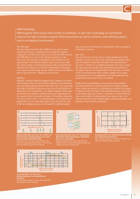
GMR TechnologyGMR magnetic field sensors from Sensitec in multilayer- or spin valve technology are particularlysuited to the high resolution magnetic field measurement as well as reference- and switching applicationsin an industrial environment.The GMR effectThe giant magnetoresistive effect (GMR) occurs in special stackscomprising thin layers of magnetic and non-magnetic materials.Compared to the AMR effect, which occurs in the bulk AMR material,the GMR effect occurs only at the interlayer boundaries of thelayer stacks. The resistance is dependent on the orientation of themagnetization of the different magnetic layers towards each other.The relative change in resistivity between parallel and perpendicularorientation lies between 10 % and 40 % depending on the specificsensor layout and technology. Sensitec GMR sensors use two differenttypes of layer structures – Multilayer and Spin valve.Multilayer:Magnetic coupling of adjacent magnetic layers, leading to an antiparallelorientation when no external field is applied, can be achieved byusing well-defined spacing between these layers (Fig. 1). By using long,thin strips of multilayer structures an easy axis and well-defined sensitivityaxis can be created (Fig. 1). An applied magnetic field in planecan overcome the magnetic coupling and turn the magnetization ofthe magnetic layers to a parallel orientation. The resulting characteristiccurve is shown in Fig. 2. It is only dependent on the magnitude ofapplied field, not on its sign with respect to the sensitivity axis. Dueto this fact multilayer sensors are well suited for switching applicationsas well as for the detection of end positions. Their sensitivity forsmall fields is very low.Spin valve:Spin valve structures can be seen as a logical development of themultilayer structure. In a layer stack comprising two magnetic layersthat are coupled in antiparallel orientation, the magnetization inone layer is “pinned” by an additional magnetic layer (Fig. 3). Usingthin long strips of spin valve stacks and pinning perpendicular tothe stripes’ long axis, the magnetization of the free layer is orientedat 90° to the pinned layer when no field is applied, due to shapeanisotropy (Fig. 4). For an applied field in the pinning direction thecharacteristic curve shown in Fig. 5 is obtained.Bridge circuits using multilayer and spin valve sensor elements:Four sensor elements are typically combined in a bridge assembly,where usually two resistors are shielded by an additional soft magneticlayer and only the change of the unshielded resistors is measuredas the bridge output. Fig. 6 shows a schematic of a half shielded spinvalve sensor bridge. The characteristic curves shown in Fig. 7 andFig.8 are obtained for half shielded bridges comprising multilayer andspinvalve sensor elements respectively.510080604020067Widerstandsänderung in %Change of resistance in %Magnetfeld Magnetic fieldAusgangsspannungOutput voltageVout-40 B sat -20 B Lin 0 B Lin 20 B sat 40Magnetische FlussdichteMagnetic flux densityV peakV offWiderstandskennlinie einer Spin valve Struktur mitFormanisotropie (Pinningrichtung: rot, free layer:blau und äußeres Magnetfeld: grün)Resistance curve of a spin-valve structure withshape anisotropy (pinning direction: red, free layer:blue and external magnetic field: green)Brückenanordung Spin valve mit 2 abgeschirmtenWiderständen (Pinningrichtung:rot, empfindlicheAchse: blau, Schirm: grün)Bridge arrangement for a spin-valve with twoshielded resistor elements (pinning direction: red,sensitive axis: blue, shield: green)Ausgangskennline einer Multilayer-Brückenschaltungmit 2 abgeschirmten ElementenTypical output voltage of a multilayer bridge circuitwith two shielded resistor elements8-B OPB switchB OPAusgangsspannungOutput voltageV rangeMagnetische FlussdichteMagnetic flux densityV ULV LL71Ausgangskennline einer Spin valve-Brückenschaltung mit zwei abgeschirmtenElementenTypical output voltage of a spin valve circuit withtwo shielded resistor elements