ODU MINI-SNAP® PC
ODU MINI-SNAP PC - Garam Elektronik AB
ODU MINI-SNAP PC - Garam Elektronik AB
- No tags were found...

Create successful ePaper yourself
Turn your PDF publications into a flip-book with our unique Google optimized e-Paper software.
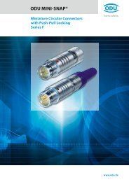
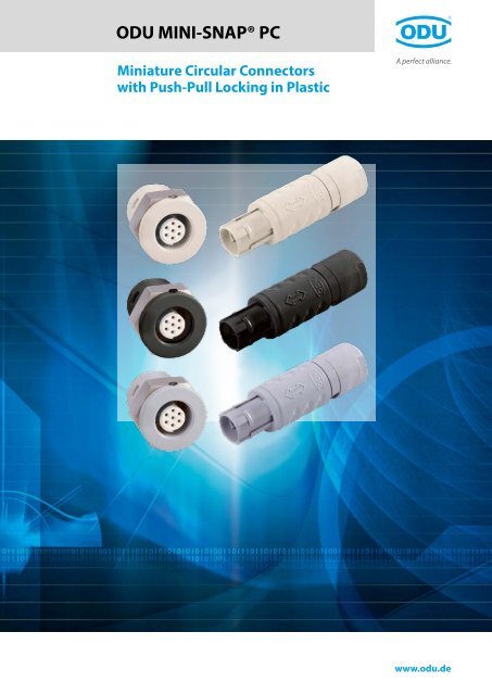
<strong>ODU</strong> <strong>MINI</strong>-<strong>SNAP®</strong> <strong>PC</strong>Miniature Circular Connectorswith Push-Pull Locking in Plasticwww.odu.de
<strong>ODU</strong> <strong>MINI</strong>-<strong>SNAP®</strong> <strong>PC</strong>Miniature Circular Connectorswith Push-Pull Locking in PlasticApplications:––Medical––Industrial––Measurement and testing––Military and security––Energy––AutomotiveProperties:––Fast and easy mating and demating––Blind mating and demating inhard-to-access places easily possible––Low space requirements on the devices––Clear and reliable locking states––IP 50 and IP 67––Shielded model available––100 % protection against contact––Easy cleaning of the housing possibleAll shown connectors are connectors withoutbreaking capacity (COC) in accordance with DINEN 61984:2009.All dimensions are in mm. Some of the pictures areillustrations. Product data and specifications aresubject to change without notice.<strong>ODU</strong> <strong>MINI</strong> SNAP connectors are UL-listed under FileE110586 00RT03566.Tested to MIL (see page 77).Issue 2013-12Page 2www.odu.de
<strong>ODU</strong> <strong>MINI</strong>-<strong>SNAP®</strong> <strong>PC</strong>Table of Contents (Part I)Kapitelab Seite1 Product description <strong>ODU</strong> <strong>MINI</strong>-<strong>SNAP®</strong> <strong>PC</strong> 5The <strong>ODU</strong> <strong>MINI</strong>-SNAP family of miniaturecircular connectors features Push-PulllockingImportant issues at a glance,turned contactsContact technologyCompatibility67892 Series IP 50 113 Series IP 50, EMC protection 174 Series IP 67 235 Series IP 67, EMC protection 296 Inserts 357 Accessories 57Cable band relief made of silicon,protective caps588 Tools 61Crimping tools for stamped contactCrimping tool and contacting forturned contactsCrimp accessories and processinginformation for turned contactsSpanner wrench626465669 Assembly instruction 66Available assembly instruction 66www.odu.dePage 3
<strong>ODU</strong> <strong>MINI</strong>-<strong>SNAP®</strong> <strong>PC</strong>Table of Contents (Part II)Kapitelab Seite10 Technical information 67International protection (IP) classesDIN EN 60 529Housing materials / surfaces,insulation body materialTermination technologyConversions AWL – cross sectionCurrent load of stamped contactsCurrent load of turned contactsOperating voltage acc. toSAE AS 13441-method 3001.1Electromagnetic compatibility (EMC)Autoclaving of <strong>ODU</strong> <strong>MINI</strong>-SNAP <strong>PC</strong>connectorsTest standardTechnical information / definitions / terms686970717273747576777811 Company information 81Quality managementYour partner in many application areasOverview – all Push-Pull connector seriesfrom <strong>ODU</strong>The complete <strong>ODU</strong> product rangeEverything from one source:<strong>ODU</strong> – the system supplierApplication specific connectors82838485868712 Telefax inquiry 8913 The part number key 90Page 4www.odu.de
<strong>ODU</strong> <strong>MINI</strong>-<strong>SNAP®</strong> <strong>PC</strong>Product Description<strong>ODU</strong> <strong>MINI</strong>-<strong>SNAP®</strong> <strong>PC</strong>ProductDescriptionwww.odu.dePage 5
<strong>ODU</strong> <strong>MINI</strong>-<strong>SNAP®</strong> <strong>PC</strong>Product DescriptionThe <strong>ODU</strong> <strong>MINI</strong>-<strong>SNAP®</strong> Family of Miniature CircularConnectors Features Push-Pull LockingCircular connectors are generally available with severallocking mechanisms.The most frequently used are––Threaded-locking sleeve––Bayonet-locking––Push-Pull lockingPush-Pull connectors have a verysimple locking mechanism––As the plug is pushed into the receptacle, lockingfingers on the plug snap into the receptacle creating areliable connection between plug and receptacle.––Pulling on the cable or the rear of plug causes thelocking fingers to grab harder and a separation of plugand receptacle is almost impossible. Pulling on theouter plug housing causes the locking fingers toretract and the plug and receptacle separate easily.Page 6www.odu.de
<strong>ODU</strong> <strong>MINI</strong>-<strong>SNAP®</strong> <strong>PC</strong>Important Issues at a GlanceTurned ContactProduct DescriptionProductDescriptionCertificationThe series is certified acc and .3 sizesPlastic housing available in 3 sizes. Outside diameterbetween 12.5 mm and 19 mm. Number of contactpositions: 2 to 27 positions.Extensive range of termination possibilitiesContacts with solder, crimp and print (<strong>PC</strong>B) termination.Degree of protection IP 50 and IP 67 availableKeying using half-shellsPlug compatible with the <strong>ODU</strong> <strong>MINI</strong>-<strong>SNAP®</strong>Series F metal versionHigh profitability because––Contacts can be assembled automatically––Easy crimp contact assembly using clip technique––Easy plug assembly––Economical pricesFurther advantages:––Housing with 100 % protection against contact––Light––Low mating forces––Housing A-magnetic––Very high chemical resistance––Shielded version availableApplicationsTurned contacts are available in the diameters 0.5 to 4.0 mm.The contacts are available with following terminations:Solder, crimp and print (<strong>PC</strong>B).Mating cycles > 5,000MaterialBrassTreatment processing Ni; Au on the mating areaFor information regarding diameter, termination styleand current load please see the contact configurationsection.Termination standard pin contactsSolder Crimp clip Print (<strong>PC</strong>B)General application requirements(– 40° C to +120° C)Connectors which are autoclavable(+134° C, see page 76)Termination styleInsulation body materialPEEK●●Insulation body materialPEEKContactmaterialMs●●ContactmaterialMsCrimp termination ● ●Solder termination ● ●Printed circuit board (<strong>PC</strong>B) termination ● ●www.odu.dePage 7
<strong>ODU</strong> <strong>MINI</strong>-<strong>SNAP®</strong> <strong>PC</strong>Product DescriptionContact TechnologyIt is possible to use stamped or turned contacts in theinsulator with the <strong>ODU</strong> <strong>MINI</strong>-<strong>SNAP®</strong> <strong>PC</strong>. Stamped contactsoffer primarily economic advantages with regard to boththe part price and the total costs for assembly. Stampedcontacts are delivered as coiled stamped strips and so canbe economically, semi-automatically assembled.The advantages of the turned contacts are seen in theprocessing of small quantities (e. g. , by soldering) andthe higher current-carrying capacity of the individualcontacts. Subsequent extrusion of the connector isalso possible with solid contacts only. The diagrams showa comparison of the contact technologies.Mating cyclesStamped contactSolid contactStamped contactSolid contactTurned contactPriceCurrent-carrying capacityStamped contactSolid contactStamped contactAssembly costsStamped contactcrimpSolid contactcrimp clipSolid contactsolderPage 8www.odu.de
<strong>ODU</strong> <strong>MINI</strong>-<strong>SNAP®</strong> <strong>PC</strong>CompatibilityProduct DescriptionProductDescriptionConnection compatibilityThe <strong>ODU</strong> <strong>MINI</strong>-<strong>SNAP®</strong> <strong>PC</strong> is plug-compatible withthe metal version in the F series. Tightness between<strong>MINI</strong>-SNAP <strong>PC</strong> Version IP 67 and <strong>MINI</strong>-SNAP F seriesVersion IP 68 is not ensured, however.Insert exchangeabilityThe <strong>ODU</strong> <strong>MINI</strong>-SNAP <strong>PC</strong> is an enhancement andsupplement of the <strong>ODU</strong> <strong>MINI</strong>-SNAP metal version, andso all inserts from the metal version's F and B series insizes 1, 2 and 3 can be used in the <strong>ODU</strong> <strong>MINI</strong>-SNAP <strong>PC</strong>.There are currently roughly 100 different contactarrangements available.<strong>ODU</strong> <strong>MINI</strong>-SNAP <strong>PC</strong>: Available versions––IP 50––IP 50 + EMC protection––IP 67––IP 67 + EMC protectionInner sleeve metalized = EMC protectionwww.odu.dePage 9
<strong>ODU</strong> <strong>MINI</strong>-<strong>SNAP®</strong> <strong>PC</strong>For your NotesPage 10www.odu.de
<strong>ODU</strong> <strong>MINI</strong>-<strong>SNAP®</strong> <strong>PC</strong>Protection Class IP 50Series IP 50www.odu.dePage 11
<strong>ODU</strong> <strong>MINI</strong>-<strong>SNAP®</strong> <strong>PC</strong>Protection Class IP 50Straight Plug – IP 50Connector type1 2 3 4 5 6 7 8 9 10 11 12 13 14 15 16 17 18 19A – – 0S 1 0 Style 1: IP 50, with standard back nutL1SW-BDSW-AL2S 2 S Style 2: IP 50, with back nut for cable bend relief 1) L1SW-BDSW-AL2Dimensions in mmSize L1 L2 D SW A SW B1 1 ~ 46 ~ 35 12.5 11 112 2 ~ 52 ~ 40 15.7 14 143 3 ~ 60 ~ 45 18.7 16 17Technical data––Contact configuration see page 381)Cable bend reliefs have to be ordered separately(see page 58)Page 12www.odu.de
<strong>ODU</strong> <strong>MINI</strong>-<strong>SNAP®</strong> <strong>PC</strong>Protection Class IP 50ReceptacleConnector type1 2 3 4 5 6 7 8 9 10 11 12 13 14 15 16 17 18 19A – – 0 0 0 0Series IP 50G 1 Receptacle IP 50, installation from front of panelBlueprint panel cut-outLCSWDM2SizeDimensions in mmPanel cut-outL D C M2 SW SW ∅1 1 18.5 16.5 2.0 5.5 16.0 12.6 13.62 2 20.5 21.0 2.0 5.5 19.0 15.6 16.63 3 25.0 24.5 2.0 5.5 24.0 19.1 21.1Technical data––IP50 in mated condition––Anti-rotation feature––Contact configuration see page 38––Minimum housing wall thickness:1 mmwww.odu.dePage 13
<strong>ODU</strong> <strong>MINI</strong>-<strong>SNAP®</strong> <strong>PC</strong>Protection Class IP 50ReceptacleConnector type1 2 3 4 5 6 7 8 9 10 11 12 13 14 15 16 17 18 19A – – 0 0 0G 5 0 Style 5: IP 50, continuous thread, installation from rear orfront of panel. Front extension adjustable.LM1Blueprint panel cut-outSWDM2SW123Dimensions in mmPanel cut-outSize L D M1 M2 SW SW ∅1 18.5 19.0 5.0 5.5 16.0 12.6 13.62 20.5 21.5 5.0 5.5 19.0 15.6 16.63 25.0 28.0 5.0 5.5 24.0 19.1 21.1Technical data––IP 50 with respect to the seal of theend device––Anti-rotation feature––Contact configuration see page 38––Only for receptaclestyle 5––Only for turnedcontactsARight-AngledPrint ContactsPage 14www.odu.de
<strong>ODU</strong> <strong>MINI</strong>-<strong>SNAP®</strong> <strong>PC</strong>Protection Class IP 50In-line Receptacle – IP 50Connector type1 2 3 4 5 6 7 8 9 10 11 12 13 14 15 16 17 18 19A – – 0Series IP 50K 1 0 Style 1: IP 50, with standard – back nut 2)L1DSW-ASW-BK 2 S Style 2: IP 50, with back nut for cable bend relief 1) 2) SW-BL1DSW-ADimensions in mm1)Cable bend relief order separately (see page 58)2)Availabe with black housing onlySize L1 D SW A SW B1 1 ~ 45 12.5 11 112 2 ~ 50 15.7 14 143 3 ~ 58 18.7 16 17www.odu.dePage 15
<strong>ODU</strong> <strong>MINI</strong>-<strong>SNAP®</strong> <strong>PC</strong>Protection Class IP 50Keying PossibilitiesHousing Materials1 2 3 4 5 6 7 8 9 10 11 12 13 14 15 16 17 18 19– –1 2 3 4 5 6 7 8 9 10 11 12 13 14 15 16 17 18 19– –KeyingReceptaclefront viewSize1 2 3RemarkHousing materialsHousing material1 ● ● ●G Plastic, grey (similar to 7035)2 ● ● ●S Plastic, black (similar to 9004)9 ● ● 1)W Plastic, white (similar to 9002)1) not compatible with <strong>ODU</strong> <strong>MINI</strong>-<strong>SNAP®</strong> F seriesPlastic Cable Collet for Connector and In-line ReceptacleCollet system1 2 3 4 5 6 7 8 9 10 11 12 13 14 15 16 17 18 19– –Cable diameterin mmSize1 2 3Cable collet systemCable collet system> 1.5 – 2.5 ● 2 5> 2.5 – 3.7 ● 3 7> 3.1 – 4.5 ● 4 5> 3.7 – 4.9 ● 4 9> 4.6 – 6.0 ● ● 6 0> 4.9 – 6.0 ● 6 0> 6.1 – 7.5 ● ● 7 5> 7.6 – 9.0 ● ● 9 0> 9.1 – 10.5 ● 0 2Cable colletAnti-rotation featureCable diameterApplications:Cable collet for strain reliefProtecting the connection points when there are pulls onthe cablePage 16www.odu.de
<strong>ODU</strong> <strong>MINI</strong>-<strong>SNAP®</strong> <strong>PC</strong>Protection Class IP 50,EMC ProtectionSeries IP 50EMC Protectionwww.odu.dePage 17
<strong>ODU</strong> <strong>MINI</strong>-<strong>SNAP®</strong> <strong>PC</strong>Protection Class IP 50, EMC ProtectionStraight Plug – IP50EMC ProtectionConnector type1 2 3 4 5 6 7 8 9 10 11 12 13 14 15 16 17 18 19C – – 0Type EMCS 1 0 Style 1: IP 50, with standard – back nutL1SW-BDSW-AL2S 2 S Style 2: IP 50, with back nut for cable bend relief 1)L1SW-BDSW-AL2Dimensions in mmSize L1 L2 D SW A SW B1 1 ~ 46 ~ 35 12.5 11 112 2 ~ 52 ~ 40 15.7 14 143 3 ~ 60 ~ 45 18.7 16 17Technical data––Contact configuration see page 381)Cable bend reliefs have to be ordered separately(see page 58)Page 18www.odu.de
<strong>ODU</strong> <strong>MINI</strong>-<strong>SNAP®</strong> <strong>PC</strong>Protection Class IP 50, EMC ProtectionReceptacle – IP50EMC ProtectionConnector type1 2 3 4 5 6 7 8 9 10 11 12 13 14 15 16 17 18 19C – – 0 0 0 0Type EMCG 1 Style 1: IP 50, installation from front of panelBlueprint panel cut-outSeries IP 50EMC ProtectionLCSWDM2SizeDimensions in mmPanel cut-outL D C M2 SW SW ∅1 1 18.5 16.5 2.0 5.5 16.0 12.6 13.62 2 20.5 21.0 2.0 5.5 19.0 15.6 16.63 3 25.0 24.5 2.0 5.5 24.0 19.1 21.1Technical data––IP 50 in mated condition––Anti-rotation feature––Contact configuration see page 38––Minimum housing wall thickness:1 mm––ouch-proof when matedG 5 Style 5: IP 50, continuous thread, installation from rear orfront of panel. Front extension adjustable.LM1Blueprint panel cut-outSWDM2SWDimensions in mmPanel cut-outSize L D M1 M2 SW SW ∅Technical data––IP 50 in mated condition––Anti-rotation feature––Contact configuration see page 381 1 18.5 19.0 5.0 5.5 16.0 12.6 7.12 2 20.5 21.5 5.0 5.5 19.0 15.6 16.63 3 25.0 28.0 5.0 5.5 24.0 19.1 21.1www.odu.dePage 19
<strong>ODU</strong> <strong>MINI</strong>-<strong>SNAP®</strong> <strong>PC</strong>Protection Class IP 50, EMC ProtectionKeying PossibilitiesHousing1 2 3 4 5 6 7 8 9 10 11 12 13 14 15 16 17 18 19– –1 2 3 4 5 6 7 8 9 10 11 12 13 14 15 16 17 18 19– –KeyingReceptaclefront viewSize1 2 3RemarkHousing materialsHousing materials1 ● ● ●G Plastic, grey (similar to 7035)2 ● ● ●9 ● ● 1)1) not compatible with <strong>ODU</strong> <strong>MINI</strong>-<strong>SNAP®</strong> F seriesPage 20www.odu.de
<strong>ODU</strong> <strong>MINI</strong>-<strong>SNAP®</strong> <strong>PC</strong>Protection Class IP 50, EMC ProtectionPlastic Cable Collet for PlugsCollet system1 2 3 4 5 6 7 8 9 10 11 12 13 14 15 16 17 18 19– –Cable diameterin mmSize1 2 3Cable collet systemCable collet systemCable colletSeries IP 50EMC Protection> 1.5 – 2.5 ● 2 5> 2.5 – 3.7 ● 3 7> 3.1 – 4.5 ● 4 5Cable diameter> 3.7 – 4.9 ● 4 9> 4.6 – 6.0 ● ● 6 0> 4.9 – 6.0 ● 6 0> 6.1 – 7.5 ● ● 7 5> 7.6 – 9.0 ● ● 9 0Anti-rotation feature> 9.1 – 10.5 ● 0 2Applications:––Cable collet for strain relief––Protecting the connection points when there are pullson the cablewww.odu.dePage 21
<strong>ODU</strong> <strong>MINI</strong>-<strong>SNAP®</strong> <strong>PC</strong>For your NotesPage 22www.odu.de
<strong>ODU</strong> <strong>MINI</strong>-<strong>SNAP®</strong> <strong>PC</strong>Protection Class IP 67(when Mated)Series IP 67www.odu.dePage 23
<strong>ODU</strong> <strong>MINI</strong>-<strong>SNAP®</strong> <strong>PC</strong>Protection Class IP 67Straight Plug – IP67Connector type1 2 3 4 5 6 7 8 9 10 11 12 13 14 15 16 17 18 19A – – 0S 3 0 Style 3: IP 67, with standard – back nutL1SW-BDSW-AL2S 4 S Style 4: IP 67, with back nut for cable bend relief 1)L1SW-BDSW-AL2Dimensions in mm1)cable bend relief order separately (see page 58)SizeL1 L2 D SW-A SW-B1 1 ~ 46 ~35 12.5 11 112 2 ~ 52 ~ 40 15.7 14 143 3 ~ 60 ~45 18.7 16 17Page 24www.odu.de
<strong>ODU</strong> <strong>MINI</strong>-<strong>SNAP®</strong> <strong>PC</strong>Protection Class IP 67Receptacle – IP 67 – Style EConnector type1 2 3 4 5 6 7 8 9 10 11 12 13 14 15 16 17 18 19A – – 0 0 0 0G E Style E: IP 67, installation from front of panel Blueprint panel cut-outLCSWMDSeries IP 67Dimensions in mmPanel cut-outSize L D C M SW SW ∅1 1 22.0 18.5 ~ 6.0 5.5 16.0 12.6 13.62 2 24.0 22.5 ~ 6.0 5.5 19.0 15.6 16.63 3 28.5 26.5 ~ 6.0 5.5 24.0 19.1 21.1Technical data––IP 67 in mated condition––IP 50 in unmated condition––Contact configuration see page 38www.odu.dePage 25
<strong>ODU</strong> <strong>MINI</strong>-<strong>SNAP®</strong> <strong>PC</strong>Protection Class IP 67In-line Receptacle – IP 67Connector type1 2 3 4 5 6 7 8 9 10 11 12 13 14 15 16 17 18 19A – – 0K 3 0 Style 1: IP 67, with standard-back nutL1DSW-ASW-BK 4 S Style 2: IP 67, with back nut for cable bend relief 1)L1DSW-ASW-BSizeDimensions in mmL1 D SW-A SW-B1)cable bend relief order separately (see page 58)––Only available with black housing––Only available in coding 11 1 ~ 48 16.2 11 112 2 ~ 53 19.8 14 143 3 ~ 62 23 16 17Page 26www.odu.de
<strong>ODU</strong> <strong>MINI</strong>-<strong>SNAP®</strong> <strong>PC</strong>Protection Class IP 67Keying PossibilitiesHousing Material1 2 3 4 5 6 7 8 9 10 11 12 13 14 15 16 17 18 19– –1 2 3 4 5 6 7 8 9 10 11 12 13 14 15 16 17 18 19– –KeyingReceptaclefront viewSize1 2 3RemarkHousing materialsHousing materials1 ● ● ●2 ● ● ●G Plastic, grey (similar to RAL 7035)S Plastic, black (similar to RAL 9004)Series IP 679 ● ● 1)W Plastic, white (similar to RAL 9002)1) Not compatible to <strong>ODU</strong> <strong>MINI</strong>-SNAP ® Series Fwww.odu.dePage 27
<strong>ODU</strong> <strong>MINI</strong>-<strong>SNAP®</strong> <strong>PC</strong>Protection Class IP 67Plastic Cable Collet for PlugsCollet system1 2 3 4 5 6 7 8 9 10 11 12 13 14 15 16 17 18 19– –Cable diameterin mmSize1 2 3Collet systemCollet systemCable collet> 1.5 – 2.5 ● 2 5> 2.5 – 3.7 ● 3 7> 3.1 – 4.5 ● 4 5Cable diameter> 3.7 – 4.9 ● 4 9> 4.6 – 6.0 ● ● 6 0> 4.9 – 6.0 ● 6 0> 6.1 – 7.5 ● ● 7 5> 7.6 – 9.0 ● ● 9 0Anti-rotation feature> 9.1 – 10.5 ● 0 2Application:––Cable collet for strain relief––Protecting the connection points when there arepulls on the cable––Seal between cable and connector housingPage 28www.odu.de
<strong>ODU</strong> <strong>MINI</strong>-<strong>SNAP®</strong> <strong>PC</strong>Protection Class IP 67,(in Mated Condition)EMC ProtectionSeries IP 67EMC Protectionwww.odu.dePage 29
<strong>ODU</strong> <strong>MINI</strong>-<strong>SNAP®</strong> <strong>PC</strong>Protection Class IP 67, EMC ProtectionReceptacle – IP 67EMC Protection – Style EConnector type1 2 3 4 5 6 7 8 9 10 11 12 13 14 15 16 17 18 19C – – 0 0 0 0G E Style 1: receptacle IP 60, installation from front of panel Blueprint panel cut-outLCSWDMDimensions in mmPanel cut-outSize L D C M SW SW ∅1 1 22.0 18.5 ~ 6.0 5.5 16.0 12.6 13.62 2 24.0 22.5 ~ 6.0 5.5 19.0 15.6 16.63 3 28.5 26.5 ~ 6.0 5.5 24.0 19.1 21.1Technical data––IP 67 in mated condition––IP 50 to the panel in unmatedcondition––Contact configuration see page 38Series IP 67EMC Protectionwww.odu.dePage 31
<strong>ODU</strong> <strong>MINI</strong>-<strong>SNAP®</strong> <strong>PC</strong>Protection Class IP 67, EMC ProtectionKeying PossibilitiesHousing Material1 2 3 4 5 6 7 8 9 10 11 12 13 14 15 16 17 18 19– –1 2 3 4 5 6 7 8 9 10 11 12 13 14 15 16 17 18 19– –KeyingReceptaclefront viewSize1 2 3RemarkHousing materialsHousing materials1 ● ● ●G Plastic, grey (similar to RAL 7035)2 ● ● ●9 ● ● 1)1) Not compatible to <strong>ODU</strong> <strong>MINI</strong>-SNAP ® Series FPage 32www.odu.de
<strong>ODU</strong> <strong>MINI</strong>-<strong>SNAP®</strong> <strong>PC</strong>Protection Class IP 67, EMC ProtectionPlastic Cable Collet for PlugsCable collet1 2 3 4 5 6 7 8 9 10 11 12 13 14 15 16 17 18 19– –Cable diameterin mmSize1 2 3Collet systemCollet systemCable collet> 1.5 – 2.5 ● 2 5> 2.5 – 3.7 ● 3 7> 3.1 – 4.5 ● 4 5Cable diameter> 3.7 – 4.9 ● 4 9> 4.6 – 6.0 ● ● 6 0> 4.9 – 6.0 ● 6 0> 6.1 – 7.5 ● ● 7 5> 7.6 – 9.0 ● ● 9 0Anti-rotation featureSeries IP 67EMC Protection> 9.1 – 10.5 ● 0 2Application:––Cable collet for strain relief––Protecting the connection points when there arepulls on the cable––Seal between cable and connector housingwww.odu.dePage 33
<strong>ODU</strong> <strong>MINI</strong>-<strong>SNAP®</strong> <strong>PC</strong>For your NotesPage 34www.odu.de
<strong>ODU</strong> <strong>MINI</strong>-<strong>SNAP®</strong> <strong>PC</strong>InsertsInsertswww.odu.dePage 35
<strong>ODU</strong> <strong>MINI</strong>-<strong>SNAP®</strong> <strong>PC</strong>InsertsInsulation Body Material1 2 3 4 5 6 7 8 9 10 11 12 13 14 15 16 17 18 19– –Insulation body materialInsulation body materialPPEEKTurned contactsTermination PEEK RemarkSolder ● Contacts pre-assembledCrimp with clip●Contacts are includedin the delivery separatelyPrint (<strong>PC</strong>B) ● Contacts pre-assembledStamped contactsTermination PEEK RemarkSolderCrimp with clip●●Contactspre-assembledContacts are included in thedelivery separatelyPrint (<strong>PC</strong>B) ● Contacts pre-assembled● = Possible combinationsPage 36www.odu.de
<strong>ODU</strong> <strong>MINI</strong>-<strong>SNAP®</strong> <strong>PC</strong>For your NotesInsertswww.odu.dePage 37
<strong>ODU</strong> <strong>MINI</strong>-<strong>SNAP®</strong> <strong>PC</strong>InsertsInserts for Stamped ContactsSize, number of contacts1 2 3 4 5 6 7 8 9 10 11 12 13 14 15 16 17 18 191 – –SizeInsulation bodyNumber of contactsAlignmentin useContactdiameter Nominalcurrentload percontact 1)mmAClearance andcreepagedistanceContact tocontact in mmContact tohousing in mmRated Termination View on theTest voltage134412 2)acc. SAE voltage 5) termination sidekVeffkVrmsSolderCrimp 3)Print 4)Malecontact sideFemalecontact side1 P 0 6 0 0.7 4 0.5 0.8 1.000 0.333 ● ● ●1 P 0 7 0 0.7 4 0.5 0.8 1.000 0.333 ● ● ●1 P 0 8 9 0.7 4 0.3 0.7 0.600 0.300 ● ● ●1)Derating factor see page 73.2)SAE AS13441:1998 method 3001.1 (kVeff).3)Tools for assembling see page61.4)<strong>PC</strong>B layout see page 42.5) Maximal operating voltage at sea levelup to 2.000 m acc. to SAE 13441.More information on page 74.Termination Cable cross-section Contact type Packaging unit Part number RemarkAWGmm²Crimp*SolderPrint (<strong>PC</strong>B)22/24 0.38 / 0.25 Stift 500 186.080.103.535.25126/28 0.14 / 0.08 Stift 500 186.080.103.535.15122/24 0.38 / 0.25 Buchse 500 176.082.103.535.25126/28 0.14 / 0.08 Buchse 500 176.082.103.535.151Please ordercontacts separately,not included indeliveryIncluded in insertIncluded in insert* Contacts are delivered on a spool. Larger packaging units are available.Page 38www.odu.de
<strong>ODU</strong> <strong>MINI</strong>-<strong>SNAP®</strong> <strong>PC</strong>InsertsInserts for Stamped ContactsContact type, contact surface and contact diameter1 2 3 4 5 6 7 8 9 10 11 12 13 14 15 16 17 18 19– –1 2 3 4 5 6 7 8 9 10 11 12 13 14 15 16 17 18 19– –Crimp contactsTerminationSolderContact typeContact surfaceSurfaceSocket 1 Galv. AuPin 2 Galv. AuSizeNumber ofcontactsKontakt‐ ContactdurchmesserdiameterContact diameterTerm. cross sectionTerminationcross sectionmm AWG mm 21 0.7 mm F 0 0 Order AWG contact separately mm 2Socket 3 Galv. AuCrimpPin 4 Galv. AuPrint (<strong>PC</strong>B) Socket 5 Galv. AuSolder contactsContactdiameterAnschlussdurchmesserTerminationdiameterContact diameterTerm. cross sectionTerminationcross sectionmm mm AWG mm 2mm 0.7 mm1.0 F G 0 AWG 22 0.38 mm 2Print (<strong>PC</strong>B) contactsInserts0.7 0.7 F 0 0www.odu.dePage 39
<strong>ODU</strong> <strong>MINI</strong>-<strong>SNAP®</strong> <strong>PC</strong>InsertsInserts, Turned ContactsSize 1Size, number of contacts1 2 3 4 5 6 7 8 9 10 11 12 13 14 15 16 17 18 191 – –SizeInsulation bodyNumber of contactsAlignmentin useContactdiameter Nominalcurrentload percontact 1)mmAClearanceand creepagedistanceContact tocontact in mmContact tohousing in mmRated Termination View on the termination sideTest voltage13441 2)acc. SAE voltage 5)kVeffkVrmsSolderCrimp 3)Print 4)Malecontact sideFemalecontact side1 P 0 2 0 1.3 14 1.3 0.9 1.650 0.550 ● ●1 P 0 3 0 1.3 14 1.1 0.8 1.500 0.500 ● ●1 P 0 4 0 0.9 10 1.2 0.8 1.500 0.500 ● ● ●1 P 0 5 0 0.9 10 0.8 0.8 1.200 0.400 ● ● ●1 P 0 6 0 0.7 7 0.8 0.8 1.200 0.400 ● ● ●1 P 0 7 0 0.7 7 0.8 0.8 1.200 0.400 ● ● ●1 P 0 8 9 0.7 7 0.6 0.7 1.000 0.333 ● ● ●1 P 1 0 9 0.5 5 0.5 0.8 1.000 0.333 ● ●1 P 1 2 0 0.5 5 0.5 0.6 1.000 0.333 ● ●1 P 1 4 9 0.5 5 0.5 0.5 0.900 0.300 ● ●1)Derating factor see page 73.2)SAE AS13441:1998 method 3001.1 (kVeff).3)Tools for assembling see page61.4)<strong>PC</strong>B layout see page 42.5) Maximal operating voltage at sea levelup to 2.000 m acc. to SAE 13441.More information on page 74.Page 40www.odu.de
<strong>ODU</strong> <strong>MINI</strong>-<strong>SNAP®</strong> <strong>PC</strong>InsertsInserts, Turned ContactsSize 1Contact type, contact surface and contact diameter1 2 3 4 5 6 7 8 9 10 11 12 13 14 15 16 17 18 19– –1 2 3 4 5 6 7 8 9 10 11 12 13 14 15 16 17 18 19– –Crimp contactsTerminationSolderContact typeContact surfaceSurfaceSocket L Galv. AuPin M Galv. AuSize1Number ofcontactsContactdiameterContact diameterTerm. cross sectionTerminationcross sectionmm AWG mm 26 – 7 0.7F C 0 28 – 32 0.09 / 0.04F G 0 22 – 26 0.38 / 0.154 – 5 0.9J G 0 22 – 26 0.38 / 0.15J H 0 20 – 24 0.50 / 0.25Socket N Galv. AuCrimpPin P Galv. AuPrint (<strong>PC</strong>B)Socket Q Galv. AuPin R Galv. AuSolder contactsContactdiameterTerminationdiameterContact diameterTerm. cross sectionTerminationcross sectionmm mm AWG mm 20.5 0.4 C C 0 28 0.080.7 0.6 F D 0 26 0.150.7 0.85 F G 0 22 0.380.9 0.85 J G 0 22 0.381.3 1.1 P H 0 20 0.50InsertsPrint (<strong>PC</strong>B) contacts0.5 0.5 C 0 00.7 0.5 F 0 00.9 0.7 F 0 01.3 0.7 J 0 0www.odu.dePage 41
<strong>ODU</strong> <strong>MINI</strong>-<strong>SNAP®</strong> <strong>PC</strong>Inserts<strong>PC</strong>B Layout for Print Contacts:Size 1Größe 1 GeradeKreis: 2,5 mmStrichstärke 0,5 mmGröße 1 GeradeKreis: 2,5 mmStrichstärke 0,5 mmGröße 1 GeradeKreis:Größe2,5 Größe mm1 Gerade 1 GeradeStrichstärkeKreis: Kreis: 2,5 2,5 0,5mm mmStrichstärke 0,5 0,5 mm mmStraight90° right-angledStraight90° right-angledSize 1Drill: 0,8 mmGröße 1, abgewinkeltKreise: Drill: 2,50,9 mmGröße 1, abgewinkeltKreise: 2,5 mm2-wayGröße 1, abgewinkeltKreise: 2,5 mmDrill: 0,8 mmGröße 1 GeradeKreis: 2,5 mmStrichstärke 0,5 mmGrößeDrill:1,0,9abgewinkeltmmKreisdurchmesserDrill: 0,6 mm2,5 mm Strichstärke 0,5pt Neu: 2009-02-20Größe 1, abgewinkeltKreise: 2,5 mmGerademmrke 0,5 mm3-wayGerade5 mmärkeGerade0,5 mmmmrke 0,5 mmGerademmrke 0,5 mm4-wayDrill: 0,8 mmDrill: 0,7 mmDrill: 0,8 mmDrill: 0,7 mm5-waySize 1Drill: 0,6 mmDrill: 0,7 mm7-way8-wayOn request10-wayDrill: 0,6 mmOn requestDrill: 0,6 mmDrill: 0,7 mm12-wayDrill: 0,6 mmDrill: 0,7 mmDrill: 0,6 mm6-way14-wayOn requestPage 42www.odu.de
<strong>ODU</strong> <strong>MINI</strong>-<strong>SNAP®</strong> <strong>PC</strong>For your NotesInsertswww.odu.dePage 43
<strong>ODU</strong> <strong>MINI</strong>-<strong>SNAP®</strong> <strong>PC</strong>InsertsInserts, Stamped Contacts,Size 2Size, number of contacts1 2 3 4 5 6 7 8 9 10 11 12 13 14 15 16 17 18 192 – –SizeInsulation bodyNumber of contactsAlignmentin useContactdiameter Nominalcurrentload percontact 1)mmAClearance andcreepagedistanceContact tocontact in mmKontakt zuGehäuse in mmRated Termination View on the termination sideTest voltage13441 2)acc. SAE voltage 5)kVeffkVrmsSolderCrimp 3)Print 4)Malecontact sideFemalecontact side2 P 1 2 9 0.7 4 0.6 0.9 1.000 0.333 ● ● ●2 P 1 4 9 0.7 4 0.5 0.9 1.000 0.333 ● ● ●2 P 1 6 0 0.7 4 0.5 0.8 1.000 0.333 ● ● ●1)Derating factor see page 73.2)SAE AS13441:1998 method 3001.1 (kVeff).3)Tools for assembling see page61.4)<strong>PC</strong>B layout see page 42.5) Maximal operating voltage at sea levelup to 2.000 m acc. to SAE 13441.More information on page 74.TerminationCable cross-section Contact type Packaging unit Part number RemarkAWGmm²Crimp*SolderPrint (<strong>PC</strong>B)22 / 24 0.38 / 0.25 Pin 500 186.080.103.535.25126 / 28 0.14 / 0.08 Pin 500 186.080.103.535.15122 / 24 0.38 / 0.25 Socket 500 176.081.103.535.25126 / 28 0.14 / 0.08 Socket 500 176.081.103.535.151Please ordercontacts separately,not included indeliveryIncluded in insertIncluded in insert* Contacts are delivered on a spool. Larger packaging units are available.Page 44www.odu.de
<strong>ODU</strong> <strong>MINI</strong>-<strong>SNAP®</strong> <strong>PC</strong>InsertsInserts, Stamped Contacts,Size 2Contact type, contact surface and Inserts1 2 3 4 5 6 7 8 9 10 11 12 13 14 15 16 17 18 19– –1 2 3 4 5 6 7 8 9 10 11 12 13 14 15 16 17 18 19– –Crimp contactsTerminationSolderContact typeContact surfaceSurfaceSocket 1 Galv. AuPin 2 Galv. AuSizeNumber ofcontactsContactdiameterContact diameterTerm. cross sectionTerminationcross sectionmm AWG mm 22 0.7 F 0 0 Order contact separatelySocket 3 Galv. AuCrimpPin 4 Galv. AuPrint (<strong>PC</strong>B) Socket 5 Galv. AuSolder contactsContactdiameterTerminationdiameterContact diameterTerm. cross sectionTerminationcross sectionmm mm AWG mm 20.7 1.0 F G 0 22 0.38Print (<strong>PC</strong>B) contactsInserts0.7 0.7 F 0 0www.odu.dePage 45
<strong>ODU</strong> <strong>MINI</strong>-<strong>SNAP®</strong> <strong>PC</strong>InsertsInserts, Stamped Contacts,Size 2Contact type, contact surface and contact diameter1 2 3 4 5 6 7 8 9 10 11 12 13 14 15 16 17 18 19– –1 2 3 4 5 6 7 8 9 10 11 12 13 14 15 16 17 18 19– –Crimp contactsTerminationContact typeContact surfaceSurfaceSizeNumber ofcontactsContactdiameterContact diameterTerm. cross sectionTerminationcross sectionmm AWG mm 2SolderSocket L Galv. AuPin M Galv. Au216 – 19 0.75 1.3F C 0 28 – 32 0.09 / 0.04F G 0 22 – 26 0.38 / 0.15P H 0 20 – 24 0.50 / 0.25P L 0 18 – 20 1.00 / 0.50Socket N Galv. AuCrimpPin P Galv. AuSolder contactsSocket Q Galv. AuPrint (<strong>PC</strong>B)Pin R Galv. AuContactdiameterTerminationdiameterContact diameterTerm. cross sectionTerminationcross sectionmm mm AWG mm 20.7 0.6 F D 0 26 0.150.7 0.85 F G 0 22 0.38Inserts0.9 0.85 J G 0 22 0.381.3 1.1 P H 0 20 0.501.6 1.4 S N 0 18 1.00Print (<strong>PC</strong>B) contacts0.7 0.5 F 0 00.9 0.7 J 0 01.3 0.7 P 0 01.6 0.7 S 0 0www.odu.dePage 47
<strong>ODU</strong> <strong>MINI</strong>-<strong>SNAP®</strong> <strong>PC</strong>For your NotesInsertswww.odu.dePage 49
<strong>ODU</strong> <strong>MINI</strong>-<strong>SNAP®</strong> <strong>PC</strong>InsertsInserts, Stamped Contacts,Size 3Size, number of contacts1 2 3 4 5 6 7 8 9 10 11 12 13 14 15 16 17 18 193 – –SizeInsulation bodyNumber of contactsAlignmentin useContactdiameter Nominalcurrentload percontact 1)mmAClearance andcreepagedistanceContact tocontact in mmContact tohousing in mmRated Termination View on the termination sideTest voltage13441 2)acc. SAE voltage 5)kVeffkVrmsSolderCrimp 3)Print 4)Malecontact sideFemalecontact side3 P 2 0 9 0.7 4 0.6 0.7 1.000 0.333 ● ● ●3 P 2 2 9 0.7 4 0.6 0.7 1.000 0.333 ● ● ●3 P 2 4 0 0.7 4 0.4 1.2 0.900 0.300 ● ● ●3 P 2 6 9 0.7 4 0.4 0.6 0.900 0.300 ●3 P 2 7 0 0.7 4 0.4 0.7 0.900 0.300 ● ● ●1)Derating factor see page 73.2)SAE AS13441:1998 method 3001.1 (kVeff).3)Tools for assembling see page61.4)<strong>PC</strong>B layout see page 42.5) Maximal operating voltage at sea levelup to 2.000 m acc. to SAE 13441.More information on page 74.Termination Cable cross-section Contact type Packaging unit Part number RemarkAWGmm²Crimp*SolderPrint (<strong>PC</strong>B)22/24 0.38 / 0.25 Pin 500 186.080.103.535.25126/28 0.14 / 0.08 Pin 500 186.080.103.535.15122/24 0.38 / 0.25 Socket 500 176.080.103.535.25126/28 0.14 / 0.08 Socket 500 176.080.103.535.151Please ordercontacts separately.Not included indelivery.Included in insertIncluded in insert* Contacts are delivered on a spool. Larger packaging units are available.Page 50www.odu.de
<strong>ODU</strong> <strong>MINI</strong>-<strong>SNAP®</strong> <strong>PC</strong>InsertsInserts, Stamped Contacts,Size 3Contact type, contact surface and contact diameter1 2 3 4 5 6 7 8 9 10 11 12 13 14 15 16 17 18 19– –1 2 3 4 5 6 7 8 9 10 11 12 13 14 15 16 17 18 19– –Crimp contactsTerminationSolderContact typeContact surfaceSurfaceSocket 1 Galv. AuPin 2 Galv. AuSizeNumber ofcontactsContactdiameterContact diameterTerm. cross sectionTerminationcross sectionmm AWG mm 23 0.7 F 0 0 Order contact separatelySocket 3 Galv. AuCrimpPin 4 Galv. AuPrint (<strong>PC</strong>B) Socket 5 Galv. AuSolder contactsContactdiameterTerminationdiameterContact diameterTerm. cross sectionTerminationcross sectionmm mm AWG mm 20.7 1.0 F G 0 22 0.38Print (<strong>PC</strong>B) contactsInserts0.7 0.7 F 0 0www.odu.dePage 51
<strong>ODU</strong> <strong>MINI</strong>-<strong>SNAP®</strong> <strong>PC</strong>InsertsInserts, Turned Contacts,Size 3 (Part 1)Size, number of contacts1 2 3 4 5 6 7 8 9 10 11 12 13 14 15 16 17 18 193 – –SizeInsulation bodyNumber of contactsAlignmentin useContactdiameter Nominalcurrentload percontact 1)mmAClearance andcreepagedistanceContact tocontact in mmContact tohousing in mmRated Termination View on the termination sideTest voltage13441 2)acc. SAE voltage 5)kVeffkVrmsSolderCrimp 3)Print 4)Malecontact sideFemalecontact side3 P 0 2 0 3.0 25 1.7 1.4 1.800 0.600 ●3 P 0 4 9 2.0 22 2.0 1.4 1.650 0.550 ● ●3 P 0 7 9 1.6 17 1.5 1.2 1.800 0.600 ● ● ●3 P 0 8 9 1.3 14 1.4 1.1 1.650 0.550 ● ● ●3 P 1 0 0 1.3 14 1.2 0.9 1.350 0.450 ● ●3 P 1 2 0 1.3 14 1.0 0.9 1.350 0.450 ● ●3 P 1 4 9 0.9 10 1.2 1.0 1.350 0.450 ● ● ●1)Derating factor see page 73.2)SAE AS13441:1998 method 3001.1 (kVeff).3)Tools for assembling see page61.4)<strong>PC</strong>B layout see page 42.5) Maximal operating voltage at sea levelup to 2.000 m acc. to SAE 13441.More information on page 74.Page 52www.odu.de
<strong>ODU</strong> <strong>MINI</strong>-<strong>SNAP®</strong> <strong>PC</strong>InsertsInserts, Turned Contacts,Size 3 (Part 2)Size, number of contacts1 2 3 4 5 6 7 8 9 10 11 12 13 14 15 16 17 18 192 – –SizeInsulation bodyNumber of contactsAlignmentin useContactdiameter Nominalcurrentload percontact 1)mmAClearance andcreepagedistanceContact tocontact in mmContact tohousing in mmRated Termination View on the termination sideTest voltage13441 2)acc. SAE voltage 5)kVeffkVrmsSolderCrimp 3)Print 4)Malecontact sideFemalecontact side3 P 1 5 0 0.9 10 0.9 0.8 1.100 0.366 ● ● ●3 P 1 8 0 0.9 10 0.9 0.8 1.100 0.366 ● ● ●3 P 2 0 9 0.7 7 0.9 0.8 1.100 0.366 ● ● ●3 P 2 2 9 0.7 7 0.9 0.7 1.100 0.366 ● ● ●Inserts3 P 2 4 0 0.7 7 0.7 1.2 1.000 0.333 ● ●3 P 2 6 9 0.7 7 0.7 0.6 1.000 0.333 ● ● ●3 P 2 7 0 0.7 7 0.7 0.7 1.000 0.333 ● ● ●1)Derating factor see page 73.2)SAE AS13441:1998 method 3001.1 (kVeff).3)Tools for assembling see page61.4)<strong>PC</strong>B layout see page 42.5) Maximal operating voltage at sea levelup to 2.000 m acc. to SAE 13441.More information on page 74.www.odu.dePage 53
<strong>ODU</strong> <strong>MINI</strong>-<strong>SNAP®</strong> <strong>PC</strong>InsertsInserts, Turned Contacts,Size 3Contact type, contact surface and contact diameter1 2 3 4 5 6 7 8 9 10 11 12 13 14 15 16 17 18 19– –1 2 3 4 5 6 7 8 9 10 11 12 13 14 15 16 17 18 19– –Crimp contactsTerminationContact typeContact surfaceSurfaceSizeNumber ofcontactsContactdiameterContact diameterTerm. cross sectionTerminationcross sectionmm AWG mm 2SolderSocket L Galv. AuPin M Galv. Au324 – 27 0.7 F C 0 22 – 26 0.38 / 0.15J G 0 22 – 26 0.38 / 0.1515 – 18 0.9J H 0 22 – 24 0.50 / 0.25CrimpSocket N Galv. AuPin P Galv. AuSolder contactsPrint (<strong>PC</strong>B)Socket Q Galv. AuPin R Galv. AuContactdiameterTerminationdiameterContact diameterTerm. cross sectionTerminationcross sectionmm mm AWG mm 20.7 0.6 F D 0 26 0.150.7 0.85 F G 0 22 0.380.9 0.85 J G 0 22 0.381.3 1.1 P H 0 20 0.501.6 1.4 S N 0 18 1.002.0 1.85 T Q 0 14 1.502.0 2.4 T S 0 12 2.503.0 2.7 V T 0 10 4.00Print (<strong>PC</strong>B) contacts0.5 0.5 C 0 00.7 0.5 F 0 00.9 0.7 J 0 01.3 0.7 P 0 01.6 0.7 S 0 02.0 0.7 T 0 0Page 54www.odu.de
<strong>ODU</strong> <strong>MINI</strong>-<strong>SNAP®</strong> <strong>PC</strong>Größe 3, gerade Kreisdurchmesser 2,5 mmStrichstärke 0,5ptInserts<strong>PC</strong>B Layout for Print Contacts:Size 3Straight90° right-angledStraight90° right-angledSize 3Size 32-way4-wayOn Größe request 3, gerade Kreisdurchmesser 2,5 mmGröße 3, gerade Kreisdurchmesser 2,5 mmStrichstärke 0,5ptStrichstärke 0,5ptGröße Größe 3, gerade Kreisdurchmesser 2,5 mmGröße 3, gerade 3, gerade Kreisdurchmesser Kreisdurchmesser 2,5 2,5 mm mmStrichstärke Strichstärke OnGrößerequest3, gerade 0,5pt Kreisdurchmesser 2,5 mmStrichstärke 0,5pt 0,5ptStrichstärke 0,5ptOn requestDrill:0.8 mmDrill:0.8 mmDrill:0.6 mm20-wayDrill:0.6 mmOn requestGröße 3, abgewinkelt KreStrichstärke 0,5pt7-wayDrill:0.8 mmOn request22-wayGröße 3, abgewinkelt KreisStrichstärke On request 0,5pt8-wayOn requestDrill:0.8 mmDrill:0.6 mmDrill:0.7 mmInsertsGröße 3, gerade Kreisdurchmesser 2,5 mmStrichstärke 0,5pt Neu: 2009-02-1912-wayDrill:0.8 mmOn request24-way14-wayOn requestDrill:0.6 mmDrill:0.8 mm26-wayOn request15-wayOn requestDrill:0.8 mmDrill:0.6 mmDrill:0.8 mm18-wayOn request27-waywww.odu.dePage 55
<strong>ODU</strong> <strong>MINI</strong>-<strong>SNAP®</strong> <strong>PC</strong>For your NotesPage 56www.odu.de
<strong>ODU</strong> <strong>MINI</strong>-<strong>SNAP®</strong> <strong>PC</strong>AccessoriesAccessorieswww.odu.dePage 57
<strong>ODU</strong> <strong>MINI</strong>-<strong>SNAP®</strong> <strong>PC</strong>AccessoriesCable Band Relief made of SiliconeSize Part number Dim. L Cable(outer diameter)min. max.123Colours701.023._.965.025 2.5 3.0701.023._.965.030 3.0 3.5701.023._.965.0353.5 4.0701.023._.965.040 4.0 5.0701.023._.965.050 305.0 6.0701.023._.965.060 6.0 6.5701.023._.965.070 6.5 7.5702.023._.965.0252.5 3.0702.023._.965.030 3.0 3.5702.023._.965.035 3.5 4.0702.023._.965.040 4.0 5.036702.023._.965.050 5.0 6.0702.023._.965.060 6.0 7.0702.023._.965.070 7.0 8.0702.023._.965.080 8.0 9.0703.023._.965.0404.0 5.0703.023._.965.050 5.0 6.0703.023._.965.060 6.0 7.0703.023._.965.070 7.0 8.042703.023._.965.080 8.0 9.0703.023._.965.090 9.0 10.0703.023._.965.100 10.0 11.0703.023._.965.110 11.0 12.0Please indicate colour code.Temperature rangeSilicone: – 50° C up to + 200° C, short-term up to + 230° C,autoclavableLColour code Colour RAL-no. 1)(similar)... 202 ... Red 3020... 203 ... White 9010... 204 ... Yellow 1016... 205 ... Green 6029... 206 ... Blue 5002... 207 ... Grey 7005... 208 ... Black 90051)Because of different raw materials the colours mayslightly differ from RAL numbers.Page 58www.odu.de
<strong>ODU</strong> <strong>MINI</strong>-<strong>SNAP®</strong> <strong>PC</strong>AccessoriesCap (attaches with Loop)In combination with style E ⇒ Degree of protection IP 67In combination with styles 1 and 5 ⇒ Degree of protection IP 50Size 1: IP 50, IP67, with receptacle style EABC∅B∅ EDSize Part number 1) Dimensions in mmA B C D ∅ B ∅ E1 K01 097 006 933 _ 7.80 18.80 15.10 75 17 102 K02 097 006 933 _ 8.10 19.05 15.10 85 20 133 K03 097 006 933 _ 10.30 19.7 16.00 100 25 161)With _ please, register desired lanyard material003 = White and Polyamide lanyard008 = Black and Polyamide lanyard103 = White and Polyamide lanyard108 = Black and Polyamide lanyardCap (attaches with Loop)In combination with style E ⇒ Degree of protection IP 67In combination with styles 1 and 5 ⇒ Degree of protection IP 50Size 1: IP 50, IP67, with receptacle style EABCAccessories∅B∅ 3.2DSize Part number 1) Dimensions in mmA B C D ∅ B1 K01 097 006 933_ 7.80 18.80 15.10 75 172 K02 097 006 933_ 8.10 19.05 15.10 85 203 K03 097 006 933_ 10.30 19.7 16.00 100 251)With _ please, register desired lanyard material203 = White and Polyamide lanyard208 = Black and Polyamide lanyard303 = White and Polyamide lanyard308 = Black and Polyamide lanyardwww.odu.dePage 59
<strong>ODU</strong> <strong>MINI</strong>-<strong>SNAP®</strong> <strong>PC</strong>For your NotesPage 60www.odu.de
<strong>ODU</strong> <strong>MINI</strong>-<strong>SNAP®</strong> <strong>PC</strong>ToolsToolswww.odu.dePage 61
<strong>ODU</strong> <strong>MINI</strong>-<strong>SNAP®</strong> <strong>PC</strong>ToolsCrimpThe processing of contacts by crimping in order toproduce connection lines results in a permanent,corrosion-free and securely contacted connection.It can also be executed by non-experts, and it istime-saving. The cold pressing (crimping) compressesthe conductor and contact material at the compressionpoints so that a gas-tight connection results thatcorresponds to the conductor material and cannotbe pulled apart. There is no need to reinforce theconductor material at the joint such as is the case withsoldering. Crimping is possible on the smallest andlargest cross-sections.Crimping Tools for Stamped Contacts (Part I)The contacts are supplied on a spool for the terminationcross-sections AWG 24 / 22 and AWG 28 / 26. Whenassembled, the contact can be slid into the insulatorwithout further tools with a very low force; it thensnaps into place in this insulator. Manual crimping toolfor single crimp contacts.The F crimp results in a well-defined, clean pinch.Manual crimping tool for single crimp contacts.Here single contacts are manually positioned in the tooland then crimped.Part number:080 000 040 000 000Instructions for use as PDF:003 069 001 000 000Page 62www.odu.de
<strong>ODU</strong> <strong>MINI</strong>-<strong>SNAP®</strong> <strong>PC</strong>ToolsCrimping Tools for Stamped Contacts (Part II)Manual crimp tool with roll-holder for spool goodsWith the manual crimp tool, the contact is fed on atape and automatically separated during crimping.The feed is done manually.Part number:080 000 041 000 000Instructions for use as PDF:003 068 001 000 000For further technical data please request the appropriate data sheet.Stripper crimper for automatic processingThe automatic crimping tools can process extremelyshort stripping lengths for the cable sheath, makingthem ideal for the <strong>ODU</strong> <strong>MINI</strong>-<strong>SNAP®</strong> <strong>PC</strong>.Can be ordered from:Fa. Schäfer Werkzeug undSondermaschinen GmbHwww.schaefer-werkzeugbau.cominfo@schaefer-werkzeugbau.comToolswww.odu.dePage 63
<strong>ODU</strong> <strong>MINI</strong>-<strong>SNAP®</strong> <strong>PC</strong>ToolsCrimping Tool and Contacting for Turned ContactsCrimping instructionsThe correct crimp position is reached by using the variouspositioners. You can select the correct crimp diameter byturning the adjusting screw to the selected number.The tool has a blocking system, which prevents themfrom opening before the pressing has been completed.Part number crimping tools 080.000.051.000.000Part number positionersee tableInstructions for use as PDF 003 089 001 000 000Page 64www.odu.de
<strong>ODU</strong> <strong>MINI</strong>-<strong>SNAP®</strong> <strong>PC</strong>ToolsCrimp Accessories and Processing Information for Turned ContactsSizeNumber ofcontactsContactdiameterCross section Adjustment Positioner Position Removal toolAWG mm² Pin Socket8 0.7 28 – 32 0.09 / 0.04 0.57 080.000.051.108.000 1 4 087.7CC.070.001.0008 0.7 22 – 26 0.38 / 0.15 0.57 080.000.051.108.000 1 4 087.7CC.070.001.0001236 – 7 0.7 28 – 32 0.09 / 0.04 0.57 080.000.051.108.000 3 4 087.7CC.070.001.0006 – 7 0.70.67 080.000.051.108.000 3 4 087.7CC.070.001.00022 – 26 0.38 / 0.154 – 5 0.9 0.67 080.000.051.108.000 5 6 087.7CC.090.001.0004 – 5 0.9 20 – 24 0.50 / 0.25 0.67 080.000.051.108.000 5 6 087.7CC.090.001.00016 – 19 0.7 28 – 32 0.09 / 0.04 0.57 080.000.051.110.000 1 2 087.7CC.070.001.00016 – 19 0.7 22 – 26 0.38 / 0.15 0.67 080.000.051.110.000 1 2 087.7CC.070.001.00012 0.7 28 – 32 0.09 / 0.04 0.57 080.000.051.110.000 1 2 087.7CC.070.001.00012 0.70.67 080.000.051.110.000 1 2 087.7CC.070.001.00022 – 26 0.38 / 0.1510 0.9 0.67 080.000.051.108.000 5 – 087.7CC.090.001.00010 0.9 20 – 24 0.50 / 0.25 0.67 080.000.051.108.000 5 – 087.7CC.090.001.00010 0.9 22 – 26 0.38 / 0.15 0.67 080.000.051.110.000 – 8 087.7CC.090.001.00010 0.90.67 080.000.051.110.000 – 8 087.7CC.090.001.00020 – 24 0.50 / 0.255 1.3 0.67 080.000.051.110.000 3 4 087.7CC.130.001.0005 1.3 18 – 20 1.00 / 0.50 1.12 080.000.051.110.000 3 4 087.7CC.130.001.00024 – 27 0.70.67 080.000.051.110.000 1 6 087.7CC.070.001.00022 – 26 0.38 / 0.1515 – 18 0.9 0.67 080.000.051.110.000 7 8 087.7CC.090.001.00015 – 18 0.9 20 – 24 0.50 / 0.25 0.67 080.000.051.110.000 7 8 087.7CC.090.001.000Toolswww.odu.dePage 65
<strong>ODU</strong> <strong>MINI</strong>-<strong>SNAP®</strong> <strong>PC</strong>ToolsSpanner WrenchPart number SW t B L bL598.700.001.003.000 12 2.5 24.5 115 10.0598.700.001.004.000 13 2.5 30.5 98 16.5BbSW598.700.001.005.000 14 2.5 30.5 98 16.5598.700.001.007.000 16 3.0 35.5 145 15.0t = thickness598.700.001.008.000 17 3.0 35.5 145 15.0598.700.001.013.000 19 3.0 42.0 172 16.0598.700.001.014.000 24 3.0 54.0 119 23.5Assembly InstructionAssembly instructions are available fordownload on our website:www.odu.de/downloadcenter.htmlThe following instruction sheets for assembly are availablefor download:<strong>MINI</strong>-SNAP <strong>PC</strong>(IP 50 + IP 67 identical)Page 66www.odu.de
<strong>ODU</strong> <strong>MINI</strong>-<strong>SNAP®</strong> <strong>PC</strong>Technical Information1201101009080706050403020100 1 2 3 4 5 6 7 8 9 10 11 12 13 14 15 16 17 18 19 20 21 22TechnicalInformationwww.odu.dePage 67
<strong>ODU</strong> <strong>MINI</strong>-<strong>SNAP®</strong> <strong>PC</strong>Technical InformationInternational Protection (IP) Classes DIN EN 60 529(respectively IEC 529/VDE 0470 T1)Code letters(International Protection)IPFirst code number(Protection against solid foreign bodies)6Second code number(Protection against water)5Code number Extent of protection Code number Extent of protection0 No protectionNo protection against contact,no protection against solidforeign bodies0No protection againstwaterNo protection against water1Protection againstlarge foreign bodiesProtection against large-surfacecontact with the back of thehand, protection against foreignbodies ≥ 50 mm1Protection againstdripping waterProtection against verticallyfalling water drops2Protection againstmedium-sizedforeign bodiesProtection against contact withthe fingers, protection againstforeign bodies. ≥ 12 mm2Protection againstdripping water whentiltedProtection against fallingwater drops when tilted(any angle up to 15° fromthe vertical)3Protection againstsmall foreign bodiesProtection against contact withtools, wires, or the like with≥ 2,5 mm,protection against foreign bodies≥2,5 mm3Protected againstspraying waterProtection against waterspraying at any angle up to60° from the vertical4Protection againstgranularforeign bodiesThe same as 3,except ≥ 1 mm 4Protection againstsplashing waterProtection against splashingwater from all directions5Protection againstdust depositsProtection against contact,protection against harmful dustdeposit in the interior5Protection againstwater jetProtection againstwater jet (nozzle) fromany angle6Protection againstdust ingressProtection against foreign bodies≥ 1 mm, protection againstdust ingress6Protection againstpowerfulwater jetProtection againstpowerful water jetfrom any angle7Protection againstimmersionProtection againstwater ingress duringtemporary immersion8Protection againstcontinuousimmersionProtection againstpressurized waterduring continuousimmersion9k 1)Protection againsthigh pressureProtection against waterfrom high-pressure/ steam jetcleaners1)IP ×9k is not included in EN 60529 or IEC 60529, but is included in DIN 40 050-9.Page 68www.odu.de
<strong>ODU</strong> <strong>MINI</strong>-<strong>SNAP®</strong> <strong>PC</strong>Technical InformationHousing Material and Surface FinishComponent Material SurfaceHousingHousing: shieldedBack nutSleeveCable colletNut / receptacle plasticPEIPEIPEIPEIPA/PSUPEIPartialCuNiNut / receptacle shielded Cu alloy NiStamped contactsTurned contactCu alloyCu alloyNiAu(Contact area)Sn(Connection area)NiAuInsulation Body Material (approved)Standard Unit PEEKDielectric strengthDIN 53481ASTM D-149kV / mm 19Operating temperature – ° C − 50 / +250Fire class UL – 94 – V – 0Comparative figure of the creepage pathformation CIT.IEC 60 112 V 175TechnicalInformationwww.odu.dePage 69
<strong>ODU</strong> <strong>MINI</strong>-<strong>SNAP®</strong> <strong>PC</strong>Technical InformationTermination TechnologiesContact blocks (insulation bodies with contacts) areinterchangeable between receptacle and plug. The sameapplies to the insulator with the socket contacts.As a rule the socket contact blocks are mounted in thepart under power (because touch-proof).With respect to the termination technologies, the type ofmounting used for the contacts in the insulator isimportant. <strong>ODU</strong> offers the following contact terminationstyles:––Solder––Crimp––Print (<strong>PC</strong>B)Termination styles for turned contactsSolder terminationThe contacts come mounted by the factory. The insulationbody and the pre-assembled contacts are called a contactblock.Crimp terminationA single contact is crimped to a single conductor.Subsequently, the crimped contact is pushed intothe insulation body. Crimp contacts and insulationbodies are shipped separately.Crimping creates a reliable, corrosion-free and durableconnection between the contact and the conductor.Crimping causes the crimp barrel of the contact and theconductor material to cold flow. It creates a gas-tightconnection between contact and conductor.The <strong>ODU</strong> <strong>MINI</strong>-SNAP generally requires the industrystandard 8-point crimping tool.Printed circuit board (<strong>PC</strong>B) termination<strong>PC</strong>B pins are used only for receptacles which are mounteddirectly to the <strong>PC</strong>B (Further information upon request).Solder terminationCrimp termination (Crimp-clip-contact for PEEK Insulator)Printed circuit board (<strong>PC</strong>B) terminationPage 70www.odu.de
<strong>ODU</strong> <strong>MINI</strong>-<strong>SNAP®</strong> <strong>PC</strong>Technical InformationConversions AWL – Cross Section(AWG = American Wire Gauge)The AWG system describes the cross section of a wireusing a gauge number for every 26 % increase inconductor cross section. With larger wire diameters,the AWG gauge numbers decrease; as the wire sizesincrease, the AWG gauge numbers decrease. This is onlyvalid for solid conductors.Most wires are made with stranded conductors .Compared to solid conductors stranded wires offer higherdurability, higher flexibility and better performance underbending and vibration.Stranded wires are made from wires with smaller gaugesizes (higher AWG gauge number). The AWG gaugenumber of the stranded wire is equal to that of a solidconductor of the same size wire. The cross section ofthe stranded conductor is the sum of cross sections of thesingle conductors.For example, an AWG-20 stranded wire of 7 AWG-28conductors has a cross section of 0.563 mm 2 ;an AWG-20 stranded wire with 19 AWG-32 conductorshas a cross section of 0.616 mm 2 .Source: Gore & Associates, PleinfeldConversion table: AWG-mm²Circular wireAWG Diameter CrosssectionWeight Max.resistanceInch mm mm² kg/km Ω/km10 (1) 0.1020 2.5900 5.2700 47.000 3.4510 (37/26) 1.1090 2.7500 4.5300 43.600 4.1312 (1) 0.0808 2.0500 3.3100 29.500 5.4512 (19/25) 0.0895 2.2500 3.0800 28.600 6.1412 (37/28) 0.0858 2.1800 2.9700 26.300 6.3614 (1) 0.0641 1.6300 2.0800 18.500 8.7914 (19/27) 0.0670 1.7000 1.9400 18.000 9.9414 (37/30) 0.0673 1.7100 1.8700 17.400 10.5016 (1) 0.0508 1.2900 1.3100 11.600 13.9416 (19/29) 0.0551 1.4000 1.2300 11.000 15.7018 (1) 0.0403 1.0200 0.8200 7.320 22.1818 (19/30) 0.0480 1.2200 0.9600 8.840 20.4020 (1) 0.0320 0.8130 0.5200 4.610 35.1020 (7/28) 0.0366 0.9300 0.5600 5.150 34.1020 (19/32) 0.0384 0.9800 0.6200 5.450 32.0022 (1) 0.0252 0.6400 0.3240 2.890 57.7022 (7/30) 0.0288 0.7310 0.3540 3.240 54.8022 (19/34) 0.0307 0.7800 0.3820 3.410 51.8024 (1) 0.0197 0.5000 0.1960 1.830 91.2024 (7/32) 0.0230 0.5850 0.2270 2.080 86.0024 (19/36) 0.0252 0.6400 0.2400 2.160 83.3026 (1) 0.1570 0.4000 0.1220 1.140 147.0026 (7/34) 0.0189 0.4800 0.1400 1.290 140.0026 (19/38) 0.0192 0.4870 0.1500 1.400 131.0028 (1) 0.0126 0.3200 0.0800 0.716 231.0028 (7/36) 0.0150 0.3810 0.0890 0.813 224.0028 (19/40) 0.0151 0.3850 0.0950 0.931 207.0030 (1) 0.0098 0.2500 0.0506 0.451 374.0030 (7/38) 0.0115 0.2930 0.0550 0.519 354.0030 (19/42) 0.0123 0.3120 0.0720 0.622 310.0032 (1) 0.0080 0.2030 0.0320 0.289 561.0032 (7/40) 0.0094 0.2400 0.0350 0.340 597.1032 (19/44) 0.0100 0.2540 0.0440 0.356 492.0034 (1) 0.0063 0.1600 0.0201 0.179 951.0034 (7/42) 0.0083 0.2110 0.0266 0.113 1.491.0036 (1) 0.0050 0.1270 0.0127 0.072 1.519.0036 (7/44) 0.0064 0.1630 0.0161 0.130 1.322.0038 (1) 0.0040 0.1000 0.0078 0.072 2.402.0040 (1) 0.0031 0.0800 0.0050 0.043 3.878.6042 (1) 0.0028 0.0700 0.0038 0.028 5.964.0044 (1) 0.0021 0.0540 0.0023 0.018 8.660.00TechnicalInformationwww.odu.dePage 71
<strong>ODU</strong> <strong>MINI</strong>-<strong>SNAP®</strong> <strong>PC</strong>Technical InformationCurrent Load of Stamped ContactsNominal single contact current load for pin / slotted socket (nominal diameter 0.7)12011010090AWG 28 AWG 268070Measured temperature on test sample in °C6050403020100 1 2 3 4 5 6 7 8Test current in ampereMating force:Demating force:..0.35.. N..0.33.. NConclusion:As can be seen in the diagram, for example, with a currentload of 4 A, the connection.– heats to a temperature of approx. 70° C with terminationAWG 26– heats to a temperature of approx. 79° C with connectionAWG 28Derating factorNumber of Derating factorloaded wires5 0.757 0.6510 0.5514 0.5019 0.4524 0.40Page 72www.odu.de
<strong>ODU</strong> <strong>MINI</strong>-<strong>SNAP®</strong> <strong>PC</strong>Technical InformationCurrent Load of Turned ContactsNominal single contact current load for pin / slotted socket (nominal diameter 0.5 mm – 1.6 mm)12011010090∅ 0.5 mm ∅ 0.7 mm ∅ 0.9 mm ∅ 1.3 mm ∅ 1.6 mm807060Measured temperature in °C50403020100 1 2 3 4 5 6 7 8 9 10 11 12 13 14 15 16 17 18 19 20 21 22Load current in ampereMaximum operating temperature for standard contacts:+120° CTest contact was terminated to largest possibleconductor.Connectors or cables with more than one contactor conductor generate a higher heat than a singlecontact. Therefore, a derating factor must be applied.For connectors the derating factor is applied accordingto DIN 57 298 Part 4 / VDE 0298 Part 2. The deratingfactor is used starting with 5 loaded wires (DIN 41 640 T3).Derating factorNumber of Derating factorloaded wires5 0.757 0.6510 0.5514 0.5019 0.4524 0.40TechnicalInformationwww.odu.dePage 73
<strong>ODU</strong> <strong>MINI</strong>-<strong>SNAP®</strong> <strong>PC</strong>Technical InformationOperating Voltage acc. to SAE AS 13441-Method 3001.1The values acc. to SAE AS 13441-method 3001.1 complywith MIL-Std. 1344 – method 3001. The chart valuesresults are acc. to IEC 60512-2; Test 4. The inserts havebeen tested in mated condition and the test voltagewas applied to the pin insert.75 % of the measured break-down voltage is the basicfor the further calculation. 1⁄3 of this value is thecorresponding operating voltage.CautionElectrical appliances: for various applications thesafety requirements regarding the operating voltageis even more severe! The relevant data in suchcases for the operating voltage are the creepageand clearance distances. For advice on how to choosethe proper connector please consult us and indicatethe safety standard which your product has to meet.All tests were performed at standard environmentconditions (room temperature) and can be appliedup to an altitude of 2,000 m. For any deviationsone has to consider the reduction factor acc. to therelevant standards.Test voltage: Break-down voltage × 0.75Operating voltage: Break-down voltage × 0.75 × 0.33Page 74www.odu.de
<strong>ODU</strong> <strong>MINI</strong>-<strong>SNAP®</strong> <strong>PC</strong>Technical InformationElectromagnetic Compatibility (EMC)When discussing electromagnetic compatibility (EMC)one should not only consider the device or the circuit,but also include the network and the entire datacommunication link. This involves all connectingelements such as conductors and connectors.Electromagnetic interference from the outside into theconnector can lead to system malfunctioning. The bestway to prevent this is by providing a high-qualityshield between the cable and the connector. In orderto provide reliable EMC data to our customers weengaged the services of a certified test laboratory toinvestigate the EMC characteristics of the <strong>ODU</strong> <strong>MINI</strong>-SNAP.They tested for us size 00, 0, 1, 2 and 3 <strong>MINI</strong>-SNAPconnectors.Measurements were conducted using the inductive wireor parallel wire method in accordance with test procedureVG 55214-6-2. In this set-up, the mated connector isconnected on one end to a network analyzer andterminated on the other end with a suitable impedance.The inductive wire is then mounted in close proximityalong the mated connector pair. The induction wire is aribbon cable which permits to vary the level of inductionby using more or less of the ribbon conductors.Next, a signal with a frequency range of 10 kHz to 3 GHz isconnected to the ribbon cable. The network analyzer isused to measure the amount of signal induced into theNetwork AnalyzerAttenuator 20 dBPower dividerCouplerTermination impedanceTermination impedanceInductive wireTape CouplerObject under testconnector circuit. The result is shown as the shieldingattenuation AT in dB. It is essential that all leads to theconnector are shielded so that no signal can be inducedinto the circuit at any other place except the connector.The various attenuation values are plotted on alogarithmic scale as attenuation in dB vs. frequency.An attenuation of better than – 55 dB is generallyrequired for reliable connector and system operation.It can be shown that our connectors will meet thisrequirement in all applications.The following diagram is valid for all series and standardsizes.Frequency in GHz0.01 0.10 1.00 10.000Attenuation in dB−10−20−30−40−50−60−70TechnicalInformation−80www.odu.dePage 75
<strong>ODU</strong> <strong>MINI</strong>-<strong>SNAP®</strong> <strong>PC</strong>Technical InformationAutoclaving of <strong>ODU</strong> <strong>MINI</strong>-<strong>SNAP®</strong> <strong>PC</strong> ConnectorsIf required <strong>ODU</strong> can deliver <strong>MINI</strong>-SNAP connectors for the following sterilization process: Steam-sterilization withpre-vacuum or gravitation process.Connectors were tested with autoclave equipment with reference to DIN EN 13060 at 134° C and 500 cycles.For other sterilization-processes please contact our technical support team.Sterilization curve:pressure inmbar abs.time1. Pre-vacuum1. Pressure increase1. Pressure decrease2. Pre-vacuum2. Pressure increaseTemperature increasein transitionInfluence5 min. at 134° C15 min. at 121° CPressure decreaseAfter-vacuumDrying timeVentilationVentilationIncrease of pressureSterilization CurveSterilizationDryingPlease contact our technical team for additional sterilization methods.Page 76www.odu.de
<strong>ODU</strong> <strong>MINI</strong>-<strong>SNAP®</strong> <strong>PC</strong>Technical InformationTest StandardIn the scope of quality approval the sizes 0 and 3 havebeen submitted to environmental and mechanical testsacc. to MIL. All tests have been passed.Test carried outDefinitionStandardHigh temperature MIL-STD 810 F / PV 501Low temperature MIL-STD 810 F / PV 502Temperature shock MIL-STD 810 F / PV 503Humidity MIL-STD 810 F / PV 507Salt fog MIL-STD 810 F / PV 509 and MIL-STD 1344 A / Method 1001.1Shock MIL-STD 810 F / PV 516VibrationMIL-STD 1344 A / Method 2005.1 / IVWater tightness IP 68 IEC 60529TechnicalInformationwww.odu.dePage 77
<strong>ODU</strong> <strong>MINI</strong>-<strong>SNAP®</strong> <strong>PC</strong>Technical InformationTechnical Information / Definitions / TermsAir gapShortest distance between two conductive elementsthrough the air.AutoclavabilitySee page 76.AWGSee page 71.Creepage distanceThe distance measured across the surface of a dielectricbetween two contacts or a contact and a metal part.The longer the distance, the lesser the risk of damage ortracking. Minimum creepage distances are specifiedaccording to the operating voltage and the applicableisolation group.Crimping areaThe part of a crimp barrel at which the crimp connectionis achieved by pressure deformation or by reshaping thebarrel around the conductor.Crimp barrelA hollow part of a contact which accepts one or moreconductors and which may be crimped through theapplication of a crimping tool.Crimp connectionThe permanent attachment of a contact to a conductorby pressure deformation or by reshaping the crimp barrelaround the conductor so that a good electrical andmechanical connection is established. (See page 70).ConnectorA component which terminates conductors for thepurpose of providing connection and disconnection to asuitable mating component. Depending on the fasteningto a cabinet, panel, rack etc. or a cable, they areclassification.DeliveryDelivery of the connectors usually as components(that means not assembled). Exception: Solder contactsare factory-installed in the insulation body.Fixed connectorA connector for attachment to a rigid surface (panel).Free connectorA connector for attachment to the free end of a wireor cable. Also called free hanging connector or in-linereceptacle.Insertion or withdrawal forceThe force required to fully mate or unmate a set ofconnectors without the effect of coupling, locking orsimilar devices. The insertion force is usually greaterthan the withdrawal force. Also called mating andunmating force.Insulation bodyNon-conductive part of a connector, to electrically andmechanically separate live parts and to protect againstaccidental touch.Insulation groupClassification of connectors according to the operatingand working conditions (insulation groups accordingDIN VDE 0110).KeyingSystem of projections and grooves on mating connectorswhich prevent otherwise identical connectors from beingmated. This is useful when several connectors of the samestyle are used in the same application.Lower limit temperatureThe lowest permissible temperature which a connectoror a plug-in device is allowed to be operated.At <strong>ODU</strong> <strong>MINI</strong>-SNAP -40° C.MaterialsThe contacts are made of Cu-alloy and gold-plated.The standard housings are made of Cu-alloy with amatt-chromate surface finish. All other materials andsurfaces on special request (see page 69).Mating cyclesMechanical operation of connectors and plug-in devicesby insertion and withdrawal. One mating cycle comprisesone insertion and one withdrawal operation.Nominal single contact current load Current load, whichcan load every single contact (see page 73).Nominal voltageNominal voltage characterizes a component.Operating temperature of the <strong>ODU</strong> <strong>MINI</strong>-SNAPRange between upper and lower temperature limits. −40° C to +120° C (see page 7).Print (<strong>PC</strong>B) connection(see page 70).Printed circuit boardBoards, typically made of epoxy-filled glass fibber fabric,with conductive pattern on one or both sides, or in caseof multilayer boards, also imbedded inside the board.They feature metalized holes for soldering wire-mountedcomponents or for the insertion of insertion of resilient orrigid press-in pins or instead, pads for attachingcomponents using surface mount technology (SMT).Reference currentThe current at which a connector can be operatedpermanently simultaneously through all contacts withoutreaching maximum temperature.Page 78www.odu.de
<strong>ODU</strong> <strong>MINI</strong>-<strong>SNAP®</strong> <strong>PC</strong>Technical InformationReference voltageNormal voltage (VDE 0110) for a connector.Solder termination(See page 70 termination styles)Termination cross-sectionThe indicated cross-sections correspond to a flexibleconductor design in accordance with EN 60228:2005class 5 or to a flexible conductor design (7/19 strands) inaccordance with AWG (ASTM B258-02).Termination techniquesMethods for connecting a wire to an electro-mechanicalcomponent, e. g. solderless connection according toIEC 60352: respectively such as crimp, press-in etc. orsolder connections.Test voltageThe voltage the connectors are tested, and are beingreferred on definite characteristics.Upper limit temperatureHighest permissible temperature at which a connector ora plug-in device is allowed to operate. This temperatureincludes the self-heating and the ambient temperature.At <strong>ODU</strong> <strong>MINI</strong>-SNAP +120° C (see page 73).WireWires may be provided with an insulation cover, anelectrical shielding. Cables or conductors may consist ofone or more wires.Connectors shown in this catalogue are designed tooperate at high voltages and high frequencies.Care must be taken to assure that no person can comein contact with live conductors during installationor operation of the connectors.<strong>ODU</strong> reserves the right to change design andperformance of any product to meet changingtechnical developments without prior notice. <strong>ODU</strong>reserves the right to discontinue any part in thiscatalogue without prior notice and without obligationto continue production after the change.TechnicalInformationwww.odu.dePage 79
<strong>ODU</strong> <strong>MINI</strong>-<strong>SNAP®</strong> <strong>PC</strong>For your NotesPage 80www.odu.de
<strong>ODU</strong> <strong>MINI</strong>-<strong>SNAP®</strong> <strong>PC</strong>Company Informationwww.odu.de Page 81CompanyInformation
<strong>ODU</strong> <strong>MINI</strong>-<strong>SNAP®</strong> <strong>PC</strong>Company InformationQuality Management<strong>ODU</strong> has had a powerful quality management systemin place for years. <strong>ODU</strong> has been successfully certifiedto ISO 9001 since 1994. In addition, the automotivesector of the company is certified to ISO TS 16949. Thecertification process was carried out by the internationallyactive BVQI (Bureau Veritas Quality International company.<strong>ODU</strong> is also certified according to the medical standardISO 13485: 2003 + AC: 2007.In addition, <strong>ODU</strong> is certificated to DIN EN ISO 14001:2009as well as to different certifications: VDE, UL, UL wiringharness, SCA, VG and ML.Page 82www.odu.de
<strong>ODU</strong> <strong>MINI</strong>-<strong>SNAP®</strong> <strong>PC</strong>Company InformationYour Partner in Many Application AreasMedical<strong>ODU</strong> stands for quality, flexibility and reliability. This iswhy customers working in many application areas rely on<strong>ODU</strong> products in markets such as the following:Industrial––Medical––Industrial––Measurement and testing––Military and security––Energy––AutomotiveMeasuring and testingMilitary and securityEnergyAutomotivewww.odu.dePage 83CompanyInformation
<strong>ODU</strong> <strong>MINI</strong>-<strong>SNAP®</strong> <strong>PC</strong>Company InformationOverview – All Push-Pull Connector Series from <strong>ODU</strong>Push pull locking Coding SizesNo. ofmechanicalcodingDiameterplug (mm)Max cable∅ (mm)Max no. ofcontactsSolderCrimpprintIOProtectionClass A 1)IPProtectionClass B 2)00 4 6.5 3.5 040 6 9.5 5.6 10<strong>ODU</strong><strong>MINI</strong>-SNAP L<strong>ODU</strong><strong>MINI</strong>-SNAP K<strong>ODU</strong><strong>MINI</strong>-SNAP BPin andgroovePin andgroovePin andgroove1 7 12.0 7.7 162 8 15.0 9.9 263 7 18.0 11.9 304 1 25.0 16.0 40011.0 5.0 101 4 13.0 7.0 162 16.0 9.0 263 1 19.0 10.5 304 1 25.0 14.0 400 6 9.4 5.0 101 8 12.0 7.0 162 8 15.0 9.0 263 10 18.0 10.5 30● ● ● IP 50● ● ● IP 68● ● ● IP 68toIP 68toIP 68bisIP 68<strong>ODU</strong><strong>MINI</strong>-SNAP S<strong>ODU</strong><strong>MINI</strong>-SNAP F<strong>ODU</strong> AMC<strong>ODU</strong><strong>MINI</strong>-SNAP <strong>PC</strong>InsulationbodyHalf shellPin andgrooveHalf shell01 19.412.05.07.004052 15.0 9.0 100 2 9.4 5.0 091 2 12.0 7.5 121.5 2 13.0 7.5 192 2 15.0 9.5 193 3 18.0 11.5 27014.0 5.5 101 15.9 6.5 161.5 16.5 8.0 1942 19.6 10.0 263 23.9 11.5 374 33.0 17.5 55112.5 6.0 142 3 15.7 9.0 193 18.7 10.5 27● ●● ● ●● ●● ● ●toIP 68toIP 68toIP 69KtoIP 67toIP 68toIP 68IP 68IP 50<strong>ODU</strong>MEDI-SNAPPin andgroove1 6 13.7 6.5 142 1 18.5 9.2 19● ● ●toIP 64IP 501)IP Protection Class in mated condition.2)IP Protection Class in unmated condition to the end device.Page 84www.odu.de
<strong>ODU</strong> <strong>MINI</strong>-<strong>SNAP®</strong> <strong>PC</strong>Company InformationThe Complete <strong>ODU</strong> Product RangeSingle contacts(round or flat)High current connectorsCircular connectorswith Push-Pull lockingModular rectangularconnectors<strong>PC</strong>B connectorsRobust connectorsDisposable systemsApplication specificsolutionsAMC - AdvancedMilitary ConnectorCable assemblywww.odu.dePage 85CompanyInformation
<strong>ODU</strong> <strong>MINI</strong>-<strong>SNAP®</strong> <strong>PC</strong>Company InformationEverything from one Source: <strong>ODU</strong> – the System SupplierEach connection needs its individual cable. Makeno compromises when it comes to the quality of thecomplete connection system. <strong>ODU</strong> gives you thecomplete system solution from one source, with nointermediary suppliers.Cable assembly is a very complex subject. It requiresequal measures of expertise in the areas of connectors,cables and assembly. <strong>ODU</strong> meets all these requirementsin full.Our competent assembly team tests the completesystem according to your specifications. Our assemblyservice promises you the same quality found in ourconnectors – without compromises.<strong>ODU</strong> offers you everything from one source––100 % final inspections––Production in clean room according to EN ISO14644-1possible––Automated processes (cutting, stripping, attaching)––Extrusion possible with a hot-melt and highpressure / temperature process––Ultrasound welding––EMC-compatible assembly––Application specific labelling––Widest range of potting possibilities for sealed systems––Extruded cable crossoversAdvantages for the customer––Modern manufacturing facilities in Mühldorf (Germany),Shanghai (China), and Sibiu (Romania)––Reliability thanks to our company-wide quality strategy––Products with durability and functional reliability––Production according to UL (file: E333666) possible––Inspections, such as crimp force monitoring, duringproductionPage 86www.odu.de
<strong>ODU</strong> <strong>MINI</strong>-<strong>SNAP®</strong> <strong>PC</strong>Company InformationApplication Specific ConnectorsInnovative, dynamic markets call for innovativeconnectors.“As an expert for special applications and requirements,we develop forward-looking, appropriate connectorsattuned to your needs!”In spite of the global trend toward standardizedconnectors, there are always applications that call for anapplication-specific solution.We accept this challenge and develop innovativeproducts for our customers based on our many years ofextensive know-how, our creativity and, not least, ourhigh level of vertical integration.Technology access and technology mastery, combinedwith intensive cooperation with the user, form the basisfor achieving success together. Design-to-cost is joined bydesign-for-application for the customer´s benefit.www.odu.dePage 87CompanyInformation
<strong>ODU</strong> <strong>MINI</strong>-<strong>SNAP®</strong> <strong>PC</strong>For your NotesPage 88www.odu.de
<strong>ODU</strong> <strong>MINI</strong>-<strong>SNAP®</strong> <strong>PC</strong>Fax InquiryFax-No.: +49 86 31 61 56 – 49<strong>ODU</strong> GmbH & Co. KGVertrieb <strong>ODU</strong> <strong>MINI</strong>-<strong>SNAP®</strong> <strong>PC</strong>Pregelstr. 1184453 Mühldorf am InnGERMANYCompany: __________________________________________Name: __________________________________________Department: __________________________________________Street: __________________________________________City: __________________________________________Phone: __________________________________________We require the following <strong>ODU</strong> <strong>MINI</strong>-<strong>SNAP®</strong> <strong>PC</strong> miniature circular connectors1) Connector applicationDate:2) Environment3) Connector type4) Special versionPlug Receptacle In-line receptacle5) Style6) Size7) Type8) Coding9) Colour10) Number of positions1 2 3A C1 2 9GreyBlackWhite (On request)11) Termination12) Contact type13) Cross section of wire14) Cable diameter15) Cable bend relief (colour)Solder Crimp <strong>PC</strong>BStamped contactmm²mmTurned contactAWG16) Protection class acc. DIN EN 60 52917) Operating temperature18) Electrical specs:Operating voltageOperating current19) Chemical resistance againstIP 50 (standard) IP 67 other°C max °C minV ACV DCContinuous A Short-term A seconds20) Other requirements21) Autoclavable, 134 °CYesNoRequired quantityProduction quantitywww.odu.dePage 89
<strong>ODU</strong> <strong>MINI</strong>-<strong>SNAP®</strong> <strong>PC</strong>The Part Number Key1 2 3 4 5 6 7 8 9 10 11 12 13 14 15 16 17 18 19– – 0No. Description Coding1 Connector type S = Straight plugG = ReceptacleK = In-line receptacle2 Style 1 – 9 undA – Z3 Size 1, 2, 34 Type A, C5 Coding6 Housing material / Colour8 Material insulator910Contact configuration(2 positions)11 Contact type / surface12 Contact diameter13 Termination cross section14 (2 positions)e. g. 27 = 27-wayfor special contact configurations= 0916 Collet system17 (2 positions)18 Straight plug: Back nut typeReceptacle: Type of attachment nutOrdering example for receptacle1 2 3 4 5 6 7 8 9 10 11 12 13 14 15 16 17 18 19G E 1 A 1 G – P 0 7 1 F G 0 – 0 0 0 01 = Receptacle2 = Style E = IP 673 = Size 14 = Type A5 = Coding 16 = Housing made of plastic, grey PEI8 = Insulator PEEK9 and 10 = 7-way11 = Stamped socket in solder execution12 = Contact diameter 0.7 mm13 and 14 = AWG 2216 = Version <strong>PC</strong>B termination17, 18, 19 = freePage 90Ordering example for plug1 2 3 4 5 6 7 8 9 10 11 12 13 14 15 16 17 18 19S 4 1 A 1 G – P 0 7 4 F Z 0 – 4 5 0 S1 = Straight plug2 = Style 4 = IP 673 = Size 14 = Type A5 = Coding 16 = Housing made of plastic, grey PEI8 = Insulator PEEK9 and 10 = 7-way11 = Stamped pin in crimp execution12 = Contact diameter 0.7 mm13 and 14 = AWG 28 – 2616 and 17 = Cable diameter 3.1 – 4.5 mm18 and 19 = for silicone cable bend relief(to order separately)www.odu.de
<strong>ODU</strong> <strong>MINI</strong>-<strong>SNAP®</strong> <strong>PC</strong>Please openwww.odu.dePage 91
<strong>ODU</strong> Worldwide<strong>ODU</strong> GmbH & Co. KGPregelstr. 1184453 Mühldorf a. InnGermanyTelefon: +49 8631 6156-0Telefax: +49 8631 6156-49E-Mail: zentral@odu.de<strong>ODU</strong> FranceTelefon: +33 1 3935-4690E-Mail: odu@odu.fr<strong>ODU</strong> ScandinaviaTelefon: +46 176 18261E-Mail: sales@odu.se<strong>ODU</strong> UKTelefon: +44 1509-266-433E-Mail: sales@odu-uk.co.uk<strong>ODU</strong> USATelefon: +1 805 4840540E-Mail: sales@odu-usa.com<strong>ODU</strong> Shanghai TradingTelefon: +86 21 58347828-106E-Mail: oduchina@odu.com.cnYou can find more qualifiedrepresentatives list on our web page:www.odu.de/salesStand: 2013 / 12· Catalogue – <strong>MINI</strong>-Snap <strong>PC</strong> · production:Agentur SYNEKTAR GmbH · www.synektar.de