CERAMIC COAXIAL RESONATORS
CERAMIC COAXIAL RESONATORS - Temex Ceramics
CERAMIC COAXIAL RESONATORS - Temex Ceramics
- No tags were found...

Create successful ePaper yourself
Turn your PDF publications into a flip-book with our unique Google optimized e-Paper software.
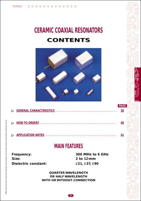
TEMEX<strong>CERAMIC</strong> <strong>COAXIAL</strong> <strong>RESONATORS</strong>CONTENTSPAGEGENERAL CHARACTERISTICS . . . . . . . . . . . . . . . . . . . . . . . . . . . . . . . . . . . . . . . . . . . . . . . . . . . . . . . . . . . 38TEMEX reserves the right to modify herein specifications and information at any time when necessary to provide optimum performance and cost.HOW TO ORDER? . . . . . . . . . . . . . . . . . . . . . . . . . . . . . . . . . . . . . . . . . . . . . . . . . . . . . . . . . . . . . . . . . . . . . . . . . . 40APPLICATION NOTES . . . . . . . . . . . . . . . . . . . . . . . . . . . . . . . . . . . . . . . . . . . . . . . . . . . . . . . . . . . . . . . . . . . . . 41Frequency:Size:Dielectric constant:MAIN FEATURES37300 MHz to 6 GHz2 to 12mmε21, ε37, ε90QUARTER WAVELENGTHOR HALF WAVELENGTHWITH OR WITHOUT CONNECTION
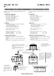
<strong>CERAMIC</strong> <strong>COAXIAL</strong> <strong>RESONATORS</strong>General characteristicsTEMEXGENERAL CHARACTERISTICSDIMENSIONS AND CONFIGURATIONSThe TEMEX coaxial resonators are available over a frequency range of 300 MHz to 6 GHz with four preferredsquare cross section sizes, having side length of 2, 4, 6 and 12 mm.Other square section dimensions 3, 8 and 10 mm (S) information can be obtained upon request.Table 1 summarizes the choice of sizes and dielectric materials available.The length of the component (L) can be determined from the chosen frequency (F) and dielectric constant(εr) as follows:(λ/4 application)(λ/2 application)L =λo4 √ εrL =λo2 √ εrλo in mmL in mmF in GHzwith λo =300FA simplified formula for λ /4 applications:IMPEDANCE Zεr = 21 L =εr = 37 L =εr = 9038L =16.37F12.3FThe coaxial resonator impedance used in TEM mode is a direct function of its dimensionsand of the dielectric material permittivity.Table 2 indicates for each standard side length, and for each dielectric constant, the impedance value,independent of the resonator length7.9FTEMEX reserves the right to modify herein specifications and information at any time when necessary to provide optimum performance and cost.
TEMEX<strong>CERAMIC</strong> <strong>COAXIAL</strong> <strong>RESONATORS</strong>General characteristicsAPPLICATIONSTEMEX coaxial ceramic resonators provide the users with “High Q” higher parallel resonantimpedance and better temperature characteristics than inductor coils and associated lumped constantelements used in RF amplifiers and oscillators circuits.These coaxial resonators are perfectly suitable for:• DRO/VCO oscillators• Cellular telephone• UHF (LC) coupled amplifiers• Global Positioning Systems (GPS)• Cordless telephone• Tuned oscillators• Narrow band filters• DuplexersTable 1: DimensionsSection S 2.0 3.0 4.0 4.0 6.0 6.0 8.0 10.0 12.0 12.0(mm) ± 0.2 ± 0.2 ± 0.2 ± 0.2 ± 0.2 ± 0.2 ± 0.2 ± 0.2 ± 0.2 ± 0.2Hole d 0.65 0.95 1.5 2.0 2.0 2.5 2.7 3.3 3.55 4.0(mm) ± 0.1 ± 0.1 ± 0.1 ± 0.1 ± 0.1 ± 0.1 ± 0.2 ± 0.2 ± 0.2 ± 0.5TEMEX Ref. CRS02 CRS03 CRS04 CRS24 CRS06 CRS26 CRS08 CRS10 CRS12 CRS412Note:(λ/4 application): all faces but (1) are metallized(λ/2 application): all faces but (1) and (2) are metallizedTEMEX reserves the right to modify herein specifications and information at any time when necessary to provide optimum performance and cost.eL1 L2Table 2: ImpedanceLTEMEX Ref. εr =21 εr = 37 εr = 90CRS02 16.5 12.5 8.0CRS03 16.0 12.0 7.5CRS04 14.0 10.5 6.5CRS24 10.0 7.5 5.0CRS06 15.5 11.5 7.5CRS26 12.5 9.5 6.0CRS08 15.0 11.5 7.0CRS10 15.5 11.5 7.5CRS12 17.0 12.5 8.0CRS412 15.5 11.5 7.5dSSection(mm)2 3 4 6 8 12L1 (mm) 0.5 0.8 0.8 1.5 1.5 2.0L2 (mm) 1.0 1.2 1.3 1.7 2.0 2.5e (mm) 0.5 0.5 0.5 0.5 0.7 1.0Table 3: General characteristicsCross section square39StandardS = 2, 3, 4, 6, 8, 12mmDielectric constant εr 21 ± 2 37 ± 1 90 ± 2Temperature coefficient21: 5 ± 5 ppmof the dielectric τf 37: 0 ± 3 ppm(Standard values)90: 0 ± 10 ppmResonant freq. range Fo See tablesFrequency toleranceStandard: ± 1 % (F)± 0.5 % (D) and otheron requestQuality factor Q See curvesImpedance Z See table 2MetallizationStandard: Silver
<strong>CERAMIC</strong> <strong>COAXIAL</strong> <strong>RESONATORS</strong>How to order?TEMEXTable 4: Standard frequency range λ/4 in MHz2 mm 3 mm 4 mm 6 mm 12 mmε21 2000 - 4000 1500 - 4000 1000 - 4000 600 - 2500 600 - 1250ε37 1500 - 3000 1500 - 3000 800 - 3000 500 - 2000 450 - 1000ε90 900 - 2000 650 - 2000 450 - 2000 450 - 1000 300 - 650For special request, please consult your local Sales Office.HOW TO ORDER?CR S 06 T Q 1500 F S 1 ECoaxial Shape Size Material Application Resonant Frequency Metallization Connection TapeResonator S: Square N: εr = 90 Q: λ / 4 frequency tolerance S: silver 1: one &T: εr = 37 H: λ / 2 (MHz) F = ± 1 % 0: none reelV: εr = 21 D = ± 0.5 % X: special5 = ± 5 MHz1 = ± 1 MHz40TEMEX reserves the right to modify herein specifications and information at any time when necessary to provide optimum performance and cost.
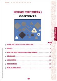
TEMEX<strong>CERAMIC</strong> <strong>COAXIAL</strong> <strong>RESONATORS</strong>Application notesAPPLICATION NOTESSOLDERING RECOMMENDATIONSBefore any soldering operation is implemented, the coaxial resonator must be preheated in orderto avoid a thermal shock and a subsequent mechanical stress liable to initiate failure mechanism.TEMEX recommends a minimum preheating time of 2 minutes at 120° C with a maximum heating rateof 2° C / sec.FREQUENCY ADJUSTMENTWhen the frequency tuning adjustment is needed, two solutions can be adopted:a) Mechanical lapping of the ceramic, or mechanical grinding of metallization, depending wheremetallization will be grinded off.b) Using a TEMEX air or sapphire dielectric tuning capacitor (“Air trimmer” or“Gigatrim”):in this case, the frequency will decrease when capacitance will increase.This provides an additional advantage of mounting / terminating resonator to the assemblyby utilizing the leg configuration of the tuning capacitor.QUALITY FACTOR QTEMEX reserves the right to modify herein specifications and information at any time when necessary to provide optimum performance and cost.The Q factor of a coaxial resonator is essentially determined by the metallization.The dielectric material, having low losses, does not have a direct effect on the “Q” (secondary influence).The curves show the range of “Q” factor versus resonator size and frequency range.Curves show that Q min. increases as frequency increases (proportionally to √Fo).41
TEMEX<strong>CERAMIC</strong> <strong>COAXIAL</strong> <strong>RESONATORS</strong>Application notes2 500Dielectric Constant = 21Q Factor2 0001 5001 00050012x126x64x43x32x200 500 1 000 1 500 2 000 2 500 3 000Frequency (MHz)Q FactorQ Factor1 8001 6001 4001 2001 00080060040020001 6001 4001 2001 000Dielectric Constant = 370 500 1 000 1 500 2 000 2 500 3 000Frequency (MHz)4212x12Dielectric Constant = 9012x12Frequency (MHz)6x64x43x38006x66004x44003x32002x200 500 1 000 1 500 2 000 2 500 3 0002x2TEMEX reserves the right to modify herein specifications and information at any time when necessary to provide optimum performance and cost.