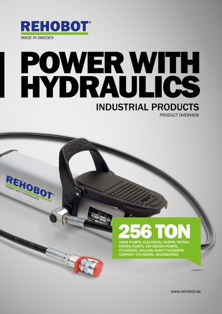
ABOUT REHOBOT HYDRAULICS
Industrial - DC Hydraulics.com
Industrial - DC Hydraulics.com

Create successful ePaper yourself
Turn your PDF publications into a flip-book with our unique Google optimized e-Paper software.
PUMPS – CREATING POWER!<strong>REHOBOT</strong> pumps have a functional design to withstand rough handling in harshenvironments. The use can be found in many different applications & industries. Thepumps can be used with all hydraulic tools and cylinders in the <strong>REHOBOT</strong>’s productrange.<strong>REHOBOT</strong> pumps are used worldwide and every possibleenvironment. Some examples can be found withinthe engineering, automotive, mining and petrochemicalindustries.We are happy to tailor the pumps to our customers'needs, thus providing flexible and cost effective solutions.Our designs are based on long experience within the fieldof hydraulics. The results are pumps that are easy to operate,repair & service - saving time and money for our customers!The usable life of <strong>REHOBOT</strong> products is extremelylong. Our pumps provide power that last for generations!Hand powered pumps – Are lightweight, portable and donot require an external power source. These pumps arecost effective, easy to use, and are ideal for workshop orfield use applications.Air powered pumps – A cost effective option for fasterand more efficient operations. No manual effort requiredby the operator. Portable and ideal for workshop use, onlystandard air-line supply required. Field use is feasible ifaccess to a compressor is available.Electrically powered pumps– The best option wherelarge capacities of oil is required: e.g. multiple cylinderoperations. By the addition of different valve types, thesepumps can easily operate multiple tools. The electricpumps are suitable in stationary installations.Petrol powered pumps – An excellent alternative where,field operations are required: e.g. construction sites andshipyards. No external power source is required.Should you be unable to find a pump to suit your requirementin the following series and table, please contact<strong>REHOBOT</strong> to discuss your application in detail.<strong>REHOBOT</strong> PUMPS ARE• Cost effective• High quality• Reliable• Ergonomically designed• Simple to usePUMP SERIES• PH - series - Single stage hand pump• PHS - series - Two stage hand pump• PME - series - Electrical powered pumps• PMP - series - Petrol powered pumps• PP - series - Air powered pumps4
Hydraulic pumpsPH - SINGLE STAGE HAND PUMPSThe single stage PH series of hand pumps are available in 700 & 800 bar workingpressures and with the option of 600 & 1000cc useable reservoir capacities.The 700 bar version are also available fully assembled with 2m long hose (LS201ES),swivel coupling (ASE10) & female half coupling AQI7. The order code for these: PH70-600/LS201 & PH70-1000/LS201.Technical tip: To ensure complete operator safety at all times we recommend thefitting of a pressure gauge (AMT801) with gauge adaptor (AVM204) to this series ofpumps.PRESSURE GAUGESPump PH70-600 equippedwith pressure gauge AMT801& gauge adaptor AVM204,used for display of thehydraulic pressure.SHUT-OFF VALVEVAD22 shot off valve increaseand improve the usage of thehand pump. Shut-off valves forhose- or direct assembly ontothe pump is included in therange of accessoriesName Part number Working Eff. oil Capacity Pump force Length Width Height Weightpressure volumeMPa cm³ cm³/stroke N mm mm mm kgPH70A-600 49100 70 600 2.9 450 590 90 170 4.5PH70A-600/LS201 49108 70 600 2.9 450 590 90 170 4.7PH70A-1000 49101 70 1000 2.9 450 590 110 170 5.2PH70A-1000/LS201 49109 70 1000 2.9 450 590 110 170 5.4PH80A-600 49102 80 600 2.9 515 590 90 170 4.5PH80A-1000 49103 80 1000 2.9 515 590 110 170 5.2Note: The hydraulic connection interface on all PH-pumps is constitued by a G1/4” threaded port.Technical tip: When fitting hoses & accessories to any hydraulic equipment, please ensure that the workingpressure rating matches or exceeds that of the pump supplying the system. Also ensure the effective oil volume ofthe pump exceeds the total oil volume of the hydraulic system.5
Hydraulic pumpsPHS - TWO STAGE HAND PUMPSThe <strong>REHOBOT</strong> Two-stage PHS hand pump comes with a pressure gauge asstandard. This gives the user a precise and safe control over the work carriedout. The gauge is directly mounted onto the pump and well protectedby the specially designed pump lever. The 2-stage function makes the pumpsimple to operate permitting the cylinder or hydraulic tool to reach its workingposition much faster compared with 1-stage pumps.• Hydraulic return connection port standard on all pumps• Robust aluminium tank with low weight and simple oil filling• Needle hold/release valve - ensures precise control over lowering operation• Mounting holes for fixed installations & handle locking system for easy carryingThe PHS-pumps with 70MPa pumps are also available fully assembled with hose including a quick coupling AQI7 andswivel coupling ASE10. Please contact <strong>REHOBOT</strong> to obtain further details and ordering information.NamePartnumberWorkingpressureEff. oilvolumeCapacitycm³/strokePumpforcePressuregaugeLength Width Height WeightMPa cm³ High-pressure Low-pressure N Type mm mm mm kgPHS70-300 44411 70 300 1 20 350 AMT801 320 110 170 6PHS70-1000 44400 70 1000 2 20 320 AMT801 620 110 170 8.1PHS70-2400 44405 70 2400 2 20 320 AMT801 620 110 170 9.9PHS70-4000 44875 70 4000 2 20 320 AMT801 620 185 170 13.7PHS80-300 44412 80 300 1 20 400 AMT801 320 110 170 6PHS80-1000 44401 80 1000 2 20 360 AMT801 620 110 170 8.1PHS80-2400 44406 80 2400 2 20 360 AMT801 620 110 170 9.9PHS80-4000 44876 80 4000 2 20 360 AMT801 620 185 170 13.7PHS100-1000 44402 100 1000 1 20 230 TX104 620 110 170 8.3PHS100-2400 44407 100 2400 1 20 230 TX104 620 110 170 10.1PHS150-1000 44403 150 1000 1 20 370 TX104 620 110 170 8.3PHS150-2400 44408 150 2400 1 20 370 TX104 620 110 170 10.1PHS150-1000L 44899 150 1000 1 20 370 AMT151 620 110 170 8.5PHS150-2400L 44903 150 2400 1 20 370 AMT151 620 110 170 10.3PHS240-2400L *) 44910 240 2400 0.7 20 460 AMT301 620 110 170 10.3*) PHS240 is ultra high pressure. All components & accessories needs to be selected for use with ultra high pressures.The hydraulic port connection interface on PHS240-2400L are 9/16” - 18UNF threaded ports with 60º Internal cone.Note: The hydraulic pressure & return connection interface on all other PHS-pumps are constituted by two G1/4” threaded ports.Technical tip: When fitting hoses & accessories to any hydraulic equipment, please ensure that the working pressurerating matches or exceeds that of the pump supplying the system. Also ensure the effective oil volume of the pumpexceeds the total oil volume of the hydraulic system.PRESSURE GAUGEAll pumps in the PHS-seriescomes with a pressure gauge asstandard. Different units for therepresentation of pressure orload can be offered.PRESSURE VALVESEach PHS-pump in the pressurerange of 70-80 MPa can beequipped with a directionalvalve. This enable operationof double acting cylinders orhydraulic tools.6
Hydraulic pumpsPME - ELECTRICALLY POWERED PUMPS<strong>REHOBOT</strong>’s electrically powered hydraulic pumps are reliable,versatile and easy to use. All pumps has a double-speed operationwith automatic switching between high and low pressureat 2 MPa - 6 MPa depending on the pump type.The low-pressure unit is a gear pump that gives a high flow up to the switchingpressure. The high-pressure unit is a single or double-piston pump.Description of the valve alternatives:ADV - Automatic release valve. Oil returns to tank whenmotor is switched off. The pressure built up in thetool then drops and the tool returns automatically.For crimping, cutting or press tools that are usedin high-frequency applications. Not for lifting applications!MRV - Manual release valve. Suitable when you want tomaintain the pressure in the tool for an extendedperiod and have a controlled release. Recommendedusage with tools for cable crimping or cutting.PME70-2030ADV and PME70-2030MRV are equipped with foot actuated pedalfor on/off control. All other models have a start/stop button placed on the motor.AP - Adapter plate. This pump has no valve, but simplya connecting plate with G1/4” pressure & returnports.MLS - With lever valve for single-acting tool/cylinder.MLD - With lever valve for double-acting tool/cylinder.SS - With solenoid valve for single-acting tool/cylinder (24 V DC). Remote control TRC230-24 or external input control is needed.SD - With solenoid valve for double-acting tool/cylinder (24 V DC). Remote control TRC230-24 or external input control is needed.Name Part number Working Eff. oilCapacityMotor Length Width Height Weightpressure volymecm³/strokeMPa cm³ Low pressure High pressure V/kW mm mm mm kgPME70-2030ADV 43005 70 3200 2700 300 230/0.55 285 285 520 23PME70-2030MRV 43006 70 3200 2700 300 230/0.55 335 285 520 23PME70-2030AP 43000 70 3200 2700 300 230/0.55 285 285 520 23PME70-2030MLS 43001 70 3200 2700 300 230/0.55 330 285 520 24PME70-2030MLD 43002 70 3200 2700 300 230/0.55 330 285 520 24PME70-2030SS 43003 70 3200 2700 300 230/0.55 380 300 520 27PME70-2030SD 43004 70 3200 2700 300 230/0.55 380 300 520 27PME70A-4100AP 43007 70 10000 7500 1600 400/2.2 335 370 575 45PME70A-4100MLS 43008 70 10000 7500 1600 400/2.2 375 370 575 46PME70A-4100MLD 43009 70 10000 7500 1600 400/2.2 375 370 575 46PME70A-4100SS 43010 70 10000 7500 1600 400/2.2 430 370 575 49PME70A-4100SD 43011 70 10000 7500 1600 400/2.2 430 370 575 49PME70A-4200AP 43012 70 20000 7500 1600 400/2.2 460 525 525 62PME70A-4200MLS 43013 70 20000 7500 1600 400/2.2 480 525 525 63PME70A-4200MLD 43014 70 20000 7500 1600 400/2.2 480 525 525 63PME70A-4200SS 43015 70 20000 7500 1600 400/2.2 460 525 525 66PME70A-4200SD 43043 70 20000 7500 1600 400/2.2 460 525 525 66Note: The hydraulic pressure & return connection interface on all PME-pumps are constituted by two G1/4” threaded ports.Technical tip! To ensure complete operator safety at all times we recommend the fitting of a pressure gauge(AMT801) with gauge adaptor (AAM14) to this series of pumps7
Hydraulic pumpsPMP - PETROL POWERED PUMPSHydraulic petrol-driven pumps with a high oil flow rate. Petrol-driven pumps are agood alternative when you need a mobile pump that does not require an externalpower source. Examples are on building sites, shipyards and in rescue situations• Double-speed pumps with automatic switchingbetween low and high pressure.• Supplied with protective frame and rubber feet.• Open design for effective cooling during operation.• Can be equipped with hose reel and other accessories.MLS - version is suitable for single acting tools.MLD - version is suitable for double acting tools.Name Part number Working Eff. oilCapacityMotor Length Width Height Weightpressure volymecm³/strokeMPa cm³ Low pressure High pressure V/kW mm mm mm kgPMP70-2100MLS 46248 70 2100 2350 550 1 cyl, 4-takt, 337 280 397 15.41.3 kWPMP70-2100MLD 46249 70 2100 2350 550 1 cyl, 4-takt,1.3 kW337 280 397 16.9Note: The hydraulic pressure & return connection interface on all PME-pumps are constituted by two G1/4” threaded ports.Technical tip! The PMP pump can be equipped with a pressure gauge for instance pressure gauge AMT801.PP - AIR HYDRAULIC PUMPS (1000-SERIES)PP-1000 air hydraulic pumps are compact pumps that operate in any position,horizontally or vertically. The pumps can easily be operated by hand or foot.• High oil flow.• Easy fill and oil level check port.• Over pressure safety valve prevents overfilling of the tank during releaseoperation which minimizes risk of injury!• Return oil hose can easily be connected to oil reservoir filler hole.Technical tip! For PP - pump series we recommend pressure gauge AMT801 & gauge adaptor AVM204.PP70-1000 - the pumps can be supplied with pre-mounted hose 2 m or 2,5 m, quick coupling(AQI7) and swivel coupling (ASE10). The product designation in such case isPP70-1000/LS201 (2m) with part nr: 45193 or PP70-1000/LS250 (2,5m) with part nr: .45192NamePart Working Eff. oilCapacityAir pressure Length Width Height Weightnumber pressure volymecm³/strokeMPaMPa cm³ Low-pressure High-perssure min max mm mm mm kgPP70B-1000 49300 70 1000 750 170 0.6 1.2 439 100 174 5.9PP80B-1000 49301 80 1000 600 160 0.6 1.2 439 100 174 5.9PP100B-1000 49302 100 1000 600 120 0.6 1.2 439 100 174 5.9Note: The hydraulic connection interface on all PP - pumps is constituted by a G1/4” threaded port.8
Hydraulic pumpsPP - AIR HYDRAULIC PUMPS (2100-SERIES)The PP-2100 series incorporates the following features:• FP, RC and MRV models have built-in releasevalve that return oil to the tank.• Sight glass allows monitoring of pump oil level.• All pumps are equipped with silencers. for quieter operation.PP-2100 series pumps are available in several different versions:FP -RC -MLD -MRV -with foot pedal for controlling start/stop and releasing.with 2,5 m remote control. Pump is controlled by two buttons onthe control unit (start/stop and release).with lever control valve for double acting hydraulic operation.with ports for pressure and return connections. Lever valve formanual release. For use with tools that have their own valve orwith a separate external valve.For PP70-2100RC/MLD/MRV pumps we recommend gauge AMT801. No adapter is needed!For PP70-2100FP pumps, we recommend gauge AMT801 and gauge adapter ATM214 for attaching the gauge to thepump.NamePart Working Eff. oilCapacityAir pressure Length Width Height Weightnumber pressure volymecm³/strokeMPaMPa cm³ Low-pressure High-pressure min max mm mm mm kgPP70-2100FP 43529 70 2100 1000 200 0.7 1.2 324 154 215 9.6PP70-2100RC 43532 70 2100 1000 200 0.7 1.2 324 154 203 10.4PP70-2100MLD 43538 70 2100 1000 200 0.7 1.2 324 154 242 10PP70-2100MRV 43544 70 2100 1000 200 0.7 1.2 324 154 199 9.3PP80-2100FP 43534 80 2100 700 150 0.6 1.2 324 154 215 9.6PP80-2100RC 43535 80 2100 700 150 0.6 1.2 324 154 203 10.4PP80-2100MLD 43536 80 2100 700 150 0.6 1.2 324 154 242 10PP80-2100MRV 43537 80 2100 700 150 0.6 1.2 324 154 199 9.3PP100-2100FP 43530 100 2100 700 100 0.7 1.2 324 154 215 10.6PP100-2100RC 43533 100 2100 700 100 0.7 1.2 324 154 203 11.2Note: The hydraulic connection interface on all PP - pumps is constituted by a G1/4” threaded port.HYDRAULIC HOSESOur original hoses are a blackpolyamide / polyurethane hosewith steel reinforcement. Thecase provides good abrasionresistance and long life.See accessories catalogue formore information on the hoses.and other accessories.QUICK COUPLINGSSwivel couplings can beinstalled on the pump,cylinders or the hydraulic tool.When using the swivel avariable (360º) couplingbetween the pump and hose isachieved.9
Hydraulic pumpsPP - AIR HYDRAULIC PUMPS (9000-SERIES)PP-9000 series pumps are delivered with remote control. Pump is controlledby two buttons on the control unit (start/stop and release).• Large tank capacity (9 liter).• 2.5m remote lead & handle controls.• Operating air pressure 6 to 12 bar• Separate pressure gauge connection.• Can easily be equipped with manifold blocks and valves ideal formulti cylinder operations.• Internal safety relief valve for overload protectionName Part number Working Eff. oilCapacityAir pressure Length Width Height Weightpressure volymecm³/strokeMPaMPa cm³ Low-pressure High-pressure min max mm mm mm kgPP70-9000RC 46545 70 9000 1000 200 0.6 1.2 340 247 311 18.4PP80-9000RC 46549 80 9000 700 150 0.6 1.2 340 247 311 18Note: The hydraulic pressure connection interface on all PP-pumps is constituted by a G1/4” threaded port.Technical tip! To ensure complete operator safety at all times we recommend the fitting of a pressure gauge.When fitting hoses & accessories to any hydraulic equipment, please ensure that the working pressure ratingmatches or exceeds that of the pump supplying the system. Also ensure the effective oil volume of the pumpexceeds the total oil volume of the hydraulic system.10
Hydraulic pumpsPower withhydraulicsHYDRAULIC CYLINDERSPRODUCT OVERVIEW256 tonPUSH CYLINDERS, PULL CYLINDERS, HOLLOWSHAFT CYLINDERS, LOW WEIGHT CYLINDERS,STAINLESS CYLINDERS, COMPACT CYLINDERSwww.rehobot.se11
CYLINDERS – HIGH POWERAT A LIMITED SPACE!<strong>REHOBOT</strong>’S cylinders are designed to withstand rough handling in harshenvironments. Their use are highly varied. The cylinders can be used whereverthere is something which needs to be pulled, pushed or lifted.<strong>REHOBOT</strong>'s cylinders are used worldwide and inall possible environments. Some examples can befound within the engineering, automotive, mining andpetrochemical industries.The standard range of products is rich with cylinders ofdifferent strokes and capacity. We also provide a widerange of accessories extending the use of the cylinders.We are happy to tailor the cylinders to our customers'needs. Something that enables flexible and cost effectivesolutions with virtually unlimited lifting capacity. Thecylinders are an effective tool for all use ranging fromsmall precision work to lifting of 500-ton bridge sections.Our designs are based on a very long experience withinthe field of hydraulics. The results are cylinders which areeasy to repair and service - saving time and money, thus<strong>REHOBOT</strong> - CYLINDERS HAS• Hard chromed pistons, making themresistant to wear and free of rust.• Galvanised cylinders for increaed corrosion resistance.• Mechnical stop for the piston movementproviding a low total cost of ownership for the user. Thepistons on our cylinders are hard chromed, making themresistant to wear and free of rust. The life of <strong>REHOBOT</strong>'sproducts is extremely long. - Our cylinders simply last forgenerations!The choice of the cylinder is normally selected by theworking operation, pressure range, stroke and boundarydimensions of the cylinder. Considerations when selectingthe cylinder for a specific application should also be givento the available range various accessories like extensiontubes, pressure heads etc. All to make the most out of thehydraulic solution.When an existing hydraulic equipment is available, theselection of cylinder preferably become based on theexisting equipment's pressure range. All to generatethegreatest flexibility and overall economy.QUICK COUPLING ON ALL CYLINDERS• AQU8 quick coupling is normally mountedon all cylinders up on delivery.• AQI24 quick coupling (female) can be equipped duringmanufacturing. In such cases shall a ’’P’’ be addedtop the product designation, e.g. CF104P.12
Hydraulic cylindersCF/CFU - SINGLE ACTING PUSH CYLINDER WITHSPRING RETURNCF cylinders are workhorses in <strong>REHOBOT</strong>’s cylinder range. They can be used for avariety of purposes. The cylinders are prepared for accessories to be connected at thepiston top or at the bottom of the cylinder. The CF - cylinders can easily be mounted inthe application by the collar mounting threads.• High strength alloy steel design for multi purpose use.• 5 to 25 capacities with 127mm - 300 stroke length.• Removable grooved piston cap & chrome piston rods.CFU - series have an extended piston pin. Used for instance for clevis fitting etc.Name Part Pressure Capacity Stroke Stroke volume Piston rod Piston area Diameter Height Weightnumber MPa kN (t) mm cm³ ø mm cm² mm mm kgCF104 27485 70 49 (5) 127 90 26.5 7.1 37.5 266 1.7CF204 27486 70 49 (5) 200 142 26.5 7.1 37.5 339 2.4CF110 43829 70 111 (11) 150 239 38 15.9 56.5 321 4.7CF210 43830 70 111 (11) 200 318 38 15.9 56.5 372 5.5CF310 43831 70 111 (11) 300 477 38 15.9 56.5 474 7CF120 24178 70 232 (24) 127 422 60 33.2 84 337 10.2CF220 24973 70 232 (24) 200 664 60 33.2 84 410 12.4CF320 24974 70 232 (24) 300 996 60 33.2 84 510 16CFU2010 43837 70 111 (11) 200 318 38 15.9 56.5 387 5.3CFU2510 43838 70 111 (11) 250 398 38 15.9 56.5 437 6CFA - ALUMINIUM PUSH CYLINDERS WITHSPRING RETURN<strong>REHOBOT</strong> push cylinders in the CFA series has a capacity between 23 & 50 ton.Aluminium material provide superior performance in the relation between capacityand weight (about 50% more power per kilo compared with similar cylinders madeof steel). The cylinders are made out of high strength aluminium which gives it amuch longer life compared with similar products on the market.• 23 to 100 ton capacity.• 100mm to 200mm stroke length.• Anodised cylinder & piston for increased wear & corrosion protection.CFA cylinders are delivered with a top lip and a protective bottom plate of steel. Allto warrant proper function even if the base and lifting points are rough.NOTE! These cylinders are designed for general service and maintenance applications. Should yourapplication require high cycle repetitive use, please contact <strong>REHOBOT</strong> to discuss your application.Name Part Pressure Capacity Stroke Stroke volume Piston Piston area Diameter Height Weightnumber MPa kN (t) mm cm³ ø mm cm² mm mm kgCFA250-100 48978 70 230 (23) 100 332 60 33.2 100 212 4.4CFA250-200 48980 70 230 (23) 200 664 60 33.2 100 312 5.9CFA500-100 47153 70 500 (51) 100 709 85 70.9 140 224 9.2CFA500-200 47160 70 500 (51) 200 1418 85 70.9 140 324 12.7CFA750-100 47187 70 730 (74) 100 1039 100 103.9 170 235.5 14CFA750-200 47188 70 730 (74) 200 2078 100 103.9 170 335.5 18.3CFA1000-100 47163 70 930 (95) 100 1327 110 132.7 190 243 18.4CFA1000-200 47171 70 930 (95) 200 2655 110 132.7 190 343 24.713
Hydraulic cylindersCFC - COMPACT SINGLE ACTING, PUSH CYLINDERSWITH SPRING RETURNCFC cylinders are real all-round cylinders. The design allows small dimensions and built inmeasurements. The cylinders are fitted with scrapers to keep the piston clean from dirt, alwaysensuring proper function in harsh environments.• Wiper polyurethane, positioned so that dirt can not penetratebetween the piston rod and cylinder• Corrosion protection - plated piston rod and electroplated cylinder• Collar mounting threads as standard.• Optional base mounting holes at the bottom of the cylinder.CFC cylinders are available in capacities between 5 to 100 tons. Models with 5 t, 10 t, 15 tand 25 tons capacity can be fitted with adapters for mounting of accessories such as pressureheads or chains, extending the use of the cylinder.Name Part Pressure Capacity Stroke Stroke volume Piston Piston area Diameter Height Weightnumber MPa kN (t) mm cm³ ø mm cm² mm mm kgCFC51 40184 70 49 (5) 27 19 25 7 38 110 0.8CFC53 40186 70 49 (5) 77 55 25 7 38 165 1.2CFC55 40188 70 49 (5) 127 90 25 7 38 216 1.5CFC57 40190 70 49 (5) 181 128 25 7 38 273 1.9CFC59 40192 70 49 (5) 232 165 25 7 38 324 2.2CFC101 40235 70 111 (11) 25 40 38 16 57 90 1.5CFC102 40237 70 111 (11) 54 86 38 16 57 121 2CFC104 40239 70 111 (11) 105 167 38 16 57 171 2.7CFC106 39849 70 111 (11) 155 247 38 16 57 247 4CFC108 39850 70 111 (11) 206 328 38 16 57 298 4.6CFC1010 39851 70 111 (11) 257 409 38 16 57 349 5.3CFC1012 39852 70 111 (11) 305 485 38 16 57 400 6CFC1014 39853 70 111 (11) 356 566 38 16 57 451 6.8CFC151 40264 70 166 (17) 25 59 48 24 70 124 3CFC152 40266 70 166 (17) 51 121 48 24 70 149 3.5CFC154 40268 70 166 (17) 101 240 48 24 70 200 4.5CFC156 39881 70 166 (17) 152 361 48 24 70 272 6.5CFC158 39882 70 166 (17) 203 482 48 24 70 322 7.5CFC1510 39883 70 166 (17) 254 603 48 24 70 373 8.5CFC1512 39884 70 166 (17) 305 725 48 24 70 424 9.5CFC1514 39885 70 166 (17) 356 846 48 24 70 475 10.9CFC251 39940 70 232 (24) 25 83 60 33 85 140 5.1CFC252 39941 70 232 (24) 51 169 60 33 85 165 5.9CFC254 39942 70 232 (24) 101 335 60 33 85 216 7.7CFC256 39943 70 232 (24) 159 528 60 33 85 273 9.7CFC258 39944 70 232 (24) 209 694 60 33 85 324 11.5CFC2510 39945 70 232 (24) 260 863 60 33 85 375 13.3CFC2512 39946 70 232 (24) 311 1032 60 33 85 426 15CFC2514 39947 70 232 (24) 362 1201 60 33 85 476 17CFC502 40292 70 496 (51) 53 376 80 71 127 176 16CFC504 40294 70 496 (51) 104 737 80 71 127 227 19CFC506 40296 70 496 (51) 159 1127 80 71 127 282 23CFC5013 40298 70 496 (51) 337 2389 80 71 127 460 35CFC756 40344 70 727 (74) 155 1610 100 104 146 282 30CFC7513 40345 70 727 (74) 333 3459 100 104 146 492 48CFC1006 40388 70 929 (95) 168 2230 100 133 175 359 54CFC10010 40389 70 929 (95) 260 3451 100 133 175 450 6514
Hydraulic cylindersCL - LOW PUSH CYLINDERS, GRAVITY RETURN• Compact design for limited space applications.• Prepared with mounting holes at bottom for fastening.• Replaceable reinforced pressure cap.CL-cylinders are ideal for those who need a compact installation dimensions.Holes in cylinder bottom makes them easy to integrate into the application.Name Part Pressure Capavity Stroke Stroke volume Piston Piston area Diameter Height Weightnumber MPa kN (t) mm cm³ ø mm cm² mm mm kgCL50-25 35680 70 49 (5) 25 18 26 7.1 39 60 0.7CLF - LOW PUSH CYLINDERSWITH SPRING RETURNCLF cylinders are the right choice for those who need flexible cylinderswith small dimensions. With capacities ranging from 5 tons to 200tons makes them suitable for lifting and other for purposes. Threadedmounting holes make them easy to integrate into various applications.The CLF series are <strong>REHOBOT</strong>’s smallest cylinder series - CLF50-10reach an height of only 37 mm, but with an incredible 5-ton liftingcapacity. Cylinders CLF670-45 and CLF1100-40 are equipped with aremovable handles to facilitate their handling.Name Part Pressure Capacity Stroke Stroke volume Piston Piston area Diameter Height WeightNumber MPa kN (t) mm cm³ ø mm cm² mm mm kgCLF50-10 35132 70 50 (5) 10 7.1 24 7.1 60 37 0.6CLF110-10 35133 70 111 (11) 10 15.9 35 15.9 80 43 1.5CLF110-30 47067 70 111 (11) 28 44.5 35 15.9 65 75 1.8CLF220-13 35320 70 218 (22) 13.5 42.1 50 31.2 100 50 2.6CLF220-50 37553 70 218 (22) 50 156 50 31.2 85 107 3.9CLF450-15 35305 70 445 (45) 15 95.4 60 63.6 134 68 6.4CLF450-40 47071 70 445 (45) 40 254.4 60 63.6 120 120 8.8CLF670-15 35413 70 665 (68) 15 142.5 80 95 146 78 9.2CLF670-45 47075 70 665 (68) 45 427.5 80 95 146 130 14.3CLF1100-15 35166 70 1078 (110) 15 231 100 154 180 90 17CLF1100-40 47079 70 1078 (110) 40 616 100 154 180 140 23.7CLF1500-15 35485 70 1498 (153) 15 321 125 214 220 100 28CLF2000-16 35490 70 1985 (202) 16 454 140 284 250 110 40HYDRAULIC HOSESOur original hose is a blackpolyamide / polyurethane hosewith steel reinforcement. Thesurface provides good abrasionresistance and long life.See accessories catalogue formore information on the hosesand other accessories.QUICK COUPLINGSSwivel couplings can beinstalled on either pump,cylinders or on the hydraulictools.When using the swivel avariable (360 º) couplingbetween the pump and hose isachieved.15
Hydraulic cylindersCX - SINGLE ACTING PUSH CYLINDERSFOR HIGH LOADSCX-series cylinders reach up to 250 ton lifting capacity. They are specially designed tocope with off-set loads. The CX-cylinder is also equipped with special piston guidance,a cylinder design which eliminate the risk of damage to the piston during movement.CX250-100 may upon request be manufactured in double-action designs and withother strokes. Please contact your <strong>REHOBOT</strong> dealer or us directly.CX series are approved for pressures up to 80 MPa (800 bar).Name Part Pressure Capacity Stroke Stroke vol. Piston Piston area Diameter Height Weightnummer MPa kN (t) mm cm³ ø mm cm² mm mm kgCX250-100 49460 80 2513 (256) 100 3140 180 314 250 285 79CSF - STAINLESS STEEL SINGLE ACTING PUSHCYLINDERS WITH SPRING RETURN• CSF-cylinders are available with 11 ton (13*) to 88 (100*)tons capacity and with 50 to 200 mm stroke length.• Designed to compensate oblique loads better than conventional cylinders.• Manufactured in stainless steel with hard chromatid piston.• Collar mounting threads as standard.All CSF - cylinders are equipped with spring return, wiper and quick coupling. ModelCSF350 has also a carrying handle mounted on the cylinder frame.*CSF-series are approved for working pressures up to 80 MPa (800 bar).NamePart Pressure Capacity Capacity Stroke Stroke vol. Piston Piston Diameter Height WeightnumberkN (t) kN (t)areaMPa at 70MPa at 80MPa mm cm³ ø mm cm² mm mm kgCSF110-50 45092 80 111 (11) 127 (13) 50 80 45 15,9 58 134 2,3CSF110-100 45094 80 111 (11) 127 (13) 100 159 45 15,9 58 184 3,0CSF110-150 45096 80 111 (11) 127 (13) 150 238 45 15,9 58 234 3,7CSF220-25 45098 80 218 (22) 249 (25) 25 78 63 31,2 80 115 3,7CSF220-50 45100 80 218 (22) 249 (25) 50 156 63 31,2 80 140 4,4CSF220-100 45102 80 218 (22) 249 (25) 100 312 63 31,2 80 190 5,9CSF220-150 45104 80 218 (22) 249 (25) 150 467 63 31,2 80 240 7,3CSF220-200 45106 80 218 (22) 249 (25) 200 623 63 31,2 80 290 8,7CSF350-50 45108 80 352 (36) 402 (41) 50 241 80 50,2 105 146 8,5CSF350-100 45110 80 352 (36) 402 (41) 100 502 80 50,2 105 196 11,0CSF350-200 45112 80 352 (36) 402 (41) 200 1005 80 50,2 105 296 15,6CSF550-50 45114 80 550 (56) 628 (64) 50 393 100 78,5 130 160 14,0CSF550-100 45116 80 550 (56) 628 (64) 100 785 100 78,5 130 210 17,7CSF550-200 45118 80 550 (56) 628 (64) 200 1570 100 78,5 130 310 24,9CSF860-50 45120 80 859 (88) 982 (100) 50 613 125 122,6 160 183 23,7CSF860-100 45122 80 859 (88) 982 (100) 100 1227 125 122,6 160 233 28,9CSF860-200 45124 80 859 (88) 982 (100) 200 2453 125 122,6 160 333 39,316
Hydraulic cylindersCH/CHF - SINGLE ACTING STEELHOLLOW BORE CYLINDERSCH / CHF hollow cylinders can due to the through-hole be used for both pushor pull operations. For example, by inserting a rod through the cylinder, thecompression force permit the cylinder to be used for pulling operations.CH / CHF cylinders have a capacity of 6 tons to 51 tons and is very compact in itsexterior dimensions. That makes them suitable for integration into applications.CH62 has a gravity return & CHF62 cylinder has a spring return function.Name Part Pressure Capacity StrokeHollowdiameterStroke vol. Piston Piston area Diameter Height Weightnumber MPa kN (t) mm mm cm³ ø mm cm² mm mm kgCH62 42503 70 61 (6) 51 17 44.7 30 8.8 55 110 1.6CHF62 45244 70 61 (6) 51 17 44.7 30 8.8 55 136 2CHFA - SINGLE ACTING ALUMINIUMHOLLOW BORE CYLINDERSCHFA series consists of cylinders made of aluminium. This makes theproducts up to 50% lighter than comparable models made out of steel.Due to its construction, hollow cylinders can be used for both push andpull operations. For example, by inserting a rod through the cylinder, thecompression force also be used for pulling operations.CHFA cylinders are available with capacities between 13 ton to 103 tonand stroke lengths up to 153 mm.NOTE! These cylinders are designed for general service and maintenance applications.Should your application require high cycle repetitive use, please contact <strong>REHOBOT</strong> to discussyour application.Name Part Pressure Capacity StrokeHollowPistonStroke PistondiameterareaDiameter Height Weightnumber MPa kN (t) mm mm cm³ ø mm cm² mm mm kgCHFA132 45862 70 123 (13) 52 22 92 40 17.6 80 165 2.3CHFA136 46602 70 123 (13) 153 22 270 40 17.6 80 310 4CHFA182 46621 70 176 (18) 51 26 128 45 25.1 94 171 3CHFA184 46622 70 176 (18) 102 26 256 45 25.1 94 246 4CHFA262 46641 70 255 (26) 51 32 186 60 36.4 115 180 4.9CHFA266 46642 70 255 (26) 153 32 557 60 36.4 115 323 8.7CHFA372 46661 70 358 (36) 51 39 261 70 51.2 136 189 6.9CHFA376 46662 70 358 (36) 153 39 784 70 51.2 136 327 12CHFA504 47733 70 508 (52) 104 51 756 80 72.7 160 276 14.7CHFA673 46681 70 659 (67) 77 54 726 100 94.2 185 250 18CHFA676 46682 70 659 (67) 153 54 1442 100 94.2 185 350 25CHFA1003 46701 70 1010 (103) 77 66 1111 120 144.3 227 284 29CHFA1006 46702 70 1010 (103) 153 66 2208 120 144.3 227 391 4017
Hydraulic cylindersCD - DOUBLE ACTING CYLINDERSCD - cylinders are double acting cylinders and used when there is a need for power atthe piston return movement. CD cylinder capacity reach between 45 tons to 200 tons,and 25 tons to 80 tons depending on the working pressure.• Collar mounting threads as standard.• Replaceable grooved saddle to protect piston.• Fitted with carrying handles as standars.• Gland will take full end loading.• 75mm to 150mm stroke option available.CD1100 - models are equipped with external thread M180x3.CD2000 - the model’s maximal operating pressure is 80 MPa.All cylinders have a maximum working pressure of 70 MPa (in case there areexceptions, these are mentioned in the text below).Name Part Capacity Stroke Stroke volume Piston Piston area Diameter Height Weightnumberpush pullpush pullpush pullkN (t) kN (t) mm cm³ cm³ ø mm cm² cm² mm mm kgCD450-75 33465 445 (45) 247 (25) 75 477 265 60 64 36 130 150 13.5CD670-150 31061 665 (68) 313 (32) 150 1425 672 80 95 45 146 300 34CD1100-100 33073 1077 (110) 285 (29) 100 1539 408 120 154 41 180 297 55CD1100-150 31060 1077 (110) 285 (29) 150 2309 614 120 154 41 180 353 66CD2000-150 38950 2035 (207) 804 (82) 150 3817 1507 140 255 100 250 300 105CPF - PULL CYLINDERSCPF cylinders are pulling cylinders of 5 tons or 11 tons capacity. Theyare part of <strong>REHOBOT</strong> push and pull kits having threads on the pistontop and cylinder bottom for attachment of accessories.• Piston and cylinder case have threads as standardfor fitting of accessories or mounting.CPF cylinders are used, for example when reshaping welded structures.Name Part Pressure Capacity Stroke Stroke volume Piston Piston area Diameter Height Weightnumber MPa kN (t) mm cm³ ø mm cm² mm mm kgCPF705 27300 70 45 (5) 125 80 20 6 48 412 2.4CPF709 27280 70 110 (11) 127 199 32 16 70 436 5.918
Hydraulic cylindersPower withhydraulicsHYDRAULIC ACCESSORIESPRODUCT OVERVIEWFLEXIBLECHAINS, HYDRAULIC OIL, EXTENSION TUBES, QUICK COUP-LINGS, VALVES, PRESSURE HEADS, MANIFOLD BLOCKS,HYDRAULIC HOSES, CYLINDER ADPTORSwww.rehobot.se19
Hydraulic accessoriesLS - HYDRAULIC HOSESHigh Pressure Hose (2800 - 6250 bar burst pressure) - is a black polyamide /polyurethane hose with steel reinforcement. Polyurethane provides good abrasionresistance and a lifetime exceeding other standard rubber hoses on themarket. The hoses are delivered with with 2 seals (part no. 17009). All hoseshave the same connection thread type on both ends of the hose.NOTE! We recommend that you always dimension by 3-4 fold margin of safety between the hydraulicsystems maximum working pressure and burst pressure of the hose.High pressure hoses (2800 - 6250 bar burst pressure)NameLengthmmø Inner/OutermmConnectionthreadLS51ES 500 6,3/13,5 G1/4”LS101ES 1000 6,3/13,5 G1/4”LS151ES 1500 6,3/13,5 G1/4”LS201ES 2000 6,3/13,5 G1/4”LS251ES 2500 6,3/13,5 G1/4”LS301ES 3000 6,3/13,5 G1/4”LS401ES 4000 6,3/13,5 G1/4”LS501ES 5000 6,3/13,5 G1/4”LS1001ES 10000 6,3/13,5 G1/4”Burst pressureMPa/bar280/2800LS303EB 3000 4,7/11,5 G1/4” 450/4500LS204ER 2000 4,7/13 9/16” UNF 1) 625/6250LS304ER 3000 4,7/13 9/16” UNF 1) 625/62501) Delivered with 9/16” UNF internal thread and a 60° external sealing cone.Highly flexible hydraulic hosesThis is a black rubber hose reinforced with two layers of braided steel reinforcement.The hose is well-suited for flexible installations. The hose aredelivered with two seals (part no. 17009).NameLengthmmø Inner/OutermmConnectionthreadLS150ES 1500 6,3/15,5 G1/4”LS200ES 2000 6,3/15,3 G1/4”LS250ES 2500 6,3/15,5 G1/4”Burst pressureMPa/bar160/1600ASE - SWIVEL COUPLINGSName Connection thread Max. working pressureASE10 G1/4” 80 MPa / 800 barASE15 G1/4” 150 MPa / 1500 barSwivel couplings can be mounted on booth cylinders, pumpsor other hydraulic tools. By means of the swivel coupling youget an flexible connection between pump/tool and hose. Thismeans more flexible operation of the tools, especially in combinedspaces.37 11 32.625Swivel couplings can rotate 360° - even under pressure.ASE10 is delivered with one seal (17009).G 1/4"25G 1/4”ASE15 does not require additional sealing when mounted ona hydraulic unit with conical connection interface.20ASE102219ASE15G 1/4”
Hydraulic accessoriesAQ - QUICK COUPLINGSAll quick couplings from <strong>REHOBOT</strong> have a checkvalve and are supplied with seals and protectioncaps made of metal or plastic.• Insert and screw type couplings.• Interchangeable with many other brands on themarket.COUPLING & SUITABLE COUNTER COUPLINGSProtection caps prevent contamination of the hydraulicsystem. Screw type couplings permit a higher flowrate than insert type couplings.BAAQU8 (Standard)AQU9AQU10-SAQU11-SBAAQI7AQI8-LBBAAQU15-DAQU25 / -DAQU39 / -DAAQI14-DAQI24 / -DAQI38-DBName Type Male Female Max. pressureMPa/barAQI7Int.threadExt.threadLockingringAmmBmmFlowl/min***Dust protectionStandard Alternative• 100/1000 G 1/4” (1) 60 27 6 TDP26 -AQI8-L • 100/1000 G 1/4” (1) • 60 27 6 TDM26 -AQU8 • 100/1000 (2) G 1/4” 39 25 6 TDP23 TDM23InsertAQU9 • 100/1000 G 3/8” 62,5 25 6 TDP23 TDM23AQU10-S* • 100/1000 (2) G 1/4” 40,5 25 6 TDP23 TDM23AQU11-SB** • 100/1000 (2) G 1/4” 40,5 25 6 TDP23 TDM23AQI14-D• 100/1000 NPT 1/4” • 48,5 30 15 TDM14 -AQU15-D • 100/1000 NPT 1/4” 34 30 15 TDM15 -AQI24 • 100/1000 (3) G 1/4” • 72 36 35 TDP24 -AQI24-D • 100/1000 (3) G 1/4” • 72 36 35 TDM24 -AQU25 Screw • 100/1000 (3) G 1/4” 52 35,5 35 TDP25 -AQU25-D • 100/1000 (3) G 1/4” 52 35,5 35 TDM25 -AQI38-D • 100/1000 NPT 3/8” • 68 36 35 TDM24 -AQU39 • 100/1000 NPT 3/8” 39 35,5 35 TDP25 -AQU39-D • 100/1000 NPT 3/8” 39 35,5 35 TDM25 -1) Addition of nipple AAU436 gives G1/4” external thread. * Coupling AQU10-S has a built-in hose rupture valve.2) Removal of nipple AAU436 gives G1/4” internal thread. ** Coupling AQU11-SB has a built-in flow restriction/check valve.3) Addition of nipple AAI456 gives G1/4” internal thread. *** Flow rate at 0,4 MPa(4 bar) pressure drop.TDP = Plastic dust protectionTDM = Metal dust protectionAQ - QUICK COUPLINGS (ULTRA-HIGH PRESSURES)Ultra high pressure systems puts high demandson the quality of the used components. Thereforeshould always <strong>REHOBOT</strong> approved accessories beselected when working with ultra high pressures.BAAQU150ABAAQI150A• Quick couplings up to 250 MPa.BAQU250BAQI250Namne Type Male Female Max. pressure.MPa/barAQI150Int.threadExt.threadAmmBmmFlowl/min**Dust protection• 150/1500 G 1/4”* - 60 27 6 PlasticAQI250 • 250/2500 G 1/4”* (2) 64 30 4,6 PlasticInsertAQU150 • 150/1500 (1)* G 1/4” 62,5 25 6 PlasticAQU250 • 250/2500 G 1/4”* (2) 55,3 25 4,6 Plastic1) Removal of nipple AAU436 gives G1/4” internal thread with 120° sealing cone.2) Adapter is required: AAU241 , AAU242 or AAU243* Female thread with internal 120° sealing cone** Flow rate is measured at 0,4 MPa(4 bar) pressure drop21
Hydraulic accessoriesAAE / TX - COUPLING NIPPLESCoupling nipples from <strong>REHOBOT</strong> Hydraulics for hydraulicsystems guarantee connectivity. The nipples can beused to adjust the thread dimensions of cylinders, hosesor ports.Note! Please observe that seals are not included in (advise the tablebelow to find the appropriate seal for your coupling nipple).NameMax. pressureMPaAExt. threadBExt. threadCInt. threadDInt. threadSeal type(see below)AAE478G 1/4” - G 3/8” - A = 2 C = 380AAE482 G 3/8” - G 1/4” - A = 3 C = 2AAE487AAE497100G 1/2” - G 1/4” - A = 4 C = 2NPTF 3/82”-18AAE498 G 1/4” -AAE499 80 G 1/4” -- G 1/4” - A = - C = 2NPTF 1/4”-18NPTF 3/8”-18- A = 2 C = -- A = 2 C = -AAE502G 1/4” - G 1/4” - A = 2 C = 2150AAE504 G 1/4” - G 1/4” - A = 2 C = 2AAE505*G 1/4” - G 1/4” - A = 2 C = 2AAI456 80- - G 1/4” G 1/4” C = 2 D = 2AAI457 - - G 1/4” G 3/8” C = 2 D = 3AAU407AAU420 100 G 1/4”G 1/4” G 3/8” - - A = 2 B = 3AAU408 G 1/4” G 1/2” - - A = 2 B = 4AAU421 G 1/4”NPTF 1/4”-18NPTF 3/8”-18- - A = 2 B = -- - A = 2 B = -AAU436 150 G 1/4” - - - A = 2TX119 100 KR 3/8” - G 1/4” - A = - B = 2TX120 80 G 1/8” - KR 3/8” - A = 1 B = -TX121G 1/8” - G 1/4” - A = 1 B = 2100TX122 G 1/4” - G 1/8” - A = 2 B = 1*AAE505 - Coupling nipple with swiveling function (before tightening).SEALSSeal type Part no For thread1 01044650 G 1 / 8”2 17009 G 1 / 4”3 16217 G 3 / 8”4 14192 G 1 / 2”To ensure a proper sealing should thesealing be selected in accordance withthe table above. This ensures a hydraulicsystem without leakage.ACABACAAE478AAE504AAU407AAU408AAU420AAU421TX119TX122DCAABAAI456AAI457AAU436AAE505Accessories for 150MPa systemsHydraulic system operatingat 1500 bar or more can bedangerous if the systems are notsealed properly.Even if all components individuallyare approved for 1500 bar ormore, there are other factors toconsider.Everything for the safe use of ultrahigh hydraulic systems.Contact us for more information!TY - HYDRAULIC OILName Volyme Oil gradeliterTY41 1 ISO VG10TY45 5 ISO VG10Hydraulic oil of high quality guaranteesexcellent functionality of your hydraulicsystem.Oil grade ISO VG10 or better shouldalways be used with <strong>REHOBOT</strong> components.22
Hydraulic accessoriesAB / AF / ATI - MANIFOLD BLOCKSIf you want to build sophisticated hydraulic systems,manifold blocks will may a necessary part of it.The manifold block is used to distribute the hydraulic flowover serveal individual ports in order to use the samepump for one or more hydraulic tools or cylinders.Note: In order to plug any unused holes, use plug part number 16536and seal with part number 17009. The seal is also used for sealingbetween the holes in manifold blocks and hose.NameMax. pressureMPa/barNumber ofportsAmmBmmCmmDmmEmmFmmGInt. threadHExt. threadAB142 45 30 22 20,5 12 21 G 1/4” G 1/4”AB38 2 45 30 22 20,5 12 21 3/8”-18 NPS G 1/4”AF55 100/1000 6 100 30 40 30 40 10 G 1/4” -AF57 8 140 30 40 30 40 50 G 1/4” -ATI289 3 45 40 27 13 25 22,5 G 1/4” -ATI33 85 25 60 12,5 - - G 1/4” G 1/4”ATI31 150/1500 3 85 25 - - - - G 1/4” G 1/4”ATI32 3 70 25 29 15 25 - G 1/4” G 1/4”AF41 300/3000 4 G 1/4” -GDDEDDHACACCACCAFBACBFBFDFBGBDEEHAHGEGGGGHBGGABEAB14AB38AF55AF57 ATI289 ATI3ATI31ATI32DUAL LIFTINGManifold blocks are a necessityfor many advanced applicationsin high pressure hydraulics, suchas the lifting of two or morecylinders.With accessories from<strong>REHOBOT</strong>, you always get partsthat fit your equipment at 100%.MULTIPLE HYDRAULIC PORTSGauge adaptor AAM14 used for gaugetype TX103 and TX104 can be mounteddirectly on the manifold blocks.In order to plug any unused hole, useplug 16536 and seal 17009.The seal is also used for sealingbetween holes in manifold blocksand hoses.23
Hydraulic accessoriesVALVES OVERVIEW<strong>REHOBOT</strong> offers many different type of valves. Ranging fromshut-off valves, with regulating functions, directional valvesand other valves for safety purposes.Note! Seals are always included for valves with trough hollow screw i.e.VAD2 & VAT3.Valve types without needs to be supplemented with seals.For thread G 1/4” use part number 17009.VA / VAD / VAT - SHUT-OFF VALVEName VA14 VAB114 VAD22 VAD2 VAT3Max pressureMPa/barSpecial function -Mountingprinciple100/1000 80/800 80/800 80/800 80/800Fixed mounting onhydraulic unit via G1/4”Built in ball valve on/off function.Fixed mounting onhydraulic unit via G1/4”Built in gauge port - -Fixed mounting onhydraulic unit via G1/4”For hose assemblyFor hose assemblyNumber of ports 2 2 2 3 42213221221222111245050VA1465G 1/4"10665G 1/4"106G 1/4"G 1/4"69G 1/4"5597G1/4"60G1/4"G 1/4”1661251245010697G 1/4"30G 1/4"30G 1/4"60G 1/4"69G 1/4"556075SHUT-OFF VALVEVAD22 mounted on a hydraulicpump model PP70-2100RC.VAD22s shut-off valve increasesthe usability of the pump bydividing the hydraulic flow intotwo separate ports.GAUGES & ADAPTORPump PH70-500 equipped with apressure gauge AMT801 & gaugeadaptor AVM204, used for displayof the hydraulic pressure.Several different units on thegauges can be suppled by<strong>REHOBOT</strong>.24
Hydraulic accessoriesVR / VRH - DIRECTIONAL VALVESVR / VRF - PRESSURE REGULATING VALVESName VR42 VRH43Max pressureMPa/bar80/800 80/800Hold function - YesName VR30 VRF31 VR150*Max pressureMPa/barComment70/700 70/700 150/1500AdjustablePreset at70 MPaAdjustable 1)A BA BP RP RP R3 3311133131131G 1/4”VR42VRH437298G 1/4"G 1/4”G 1/4"G 1/4"75G 1/4”757595G 1/4”9595G 1/4"G 1/4"G 1/4"130.5130.5130.5VR30143G 1/4"143G 1/4"143G 1/4"G 1/2"50 G 1/2"G 1/2"5050G 1/4"G 1/4"G 1/4"120120G 1/2"50G 1/2"G 1/2"5050G 1/4"120143G 1/4”2543G 1/2"G 1/4”506060Note! Please observe that seals are not included. For thread G 1/4” we recommend seal with partnumber 17009.Note! Please observe that seals are not included. For thread G 1/4” we recommendseal part number 17009 and for thread G 1/2” we recommend seal part no14192.* - Especially designed for hand pumps in the PHS-series.1) - Adjustable pressure between 50 - 150 MPa.VS - SAFETY VALVEName Preset pressure A BMPa Int. thread mmVS14-90 90 - 95 G 1/4” 42VS14-100 100 - 105 G 1/4” 42VS38-90 90 - 95 NPT 3/8” 46VS38-100 100 - 105 NPT 3/8” 46A safety valve is a useful component for preventing excessivepressures in a hydraulic system. These valves areprimarily designed for use on the return side of doubleacting hydraulic cylinders, and are preset at the factoryfor maximum pressure as shown in the table. The presetpressure must NOT be changed!38,5AB•Preset pressure at 95 or 105 MPa.•Prevents your hydraulic system from pressure overload.Note! If the preset pressure is exceeded then oil will leak out. You musttherefore ensure that the user is protected against pressurised oil.Always install the safety valve in an enclosure or protected area.G 1/4”25
Hydraulic accessoriesAMP / AMT / AMZ / TX - PRESSURE GAUGESGauges permit visual monitoring of the force and/or pressure generatedby a hydraulic pump. This helps prevent accidental overloadingand contributes to prolonging the life of your hydraulic equipment.AMT801 and TX104 are fluid-damped gauge models which are recommendedif there is a risk of pressure surges. Gauges with customisedscales can be supplied on request.NameNumberof scalesAMP651 5AMP652 5AMT650 2AMT151 2AMT301 2MeasurementrangeScale division-40 kN 2 kN-100 kN 10 kN-200 kN 10 kN-70 MPa 2 MPa-10000 psi 500 psi-400 kN 20 kN-600 kN 50 kN-1000 kN 50 kN-70 MPa 2 MPa-10000 psi 500 psi-100 MPa 2 MPa-14000 psi 500 psi-160 MPa 5 MPa-23000 psi 500 psi-310 MPa 10 MPa-45000 psi 1000 psi-100 MPa 5 MPaPistondiametermmPiston area* TX103 & TX104 can be connected directly on standard hand pumps within the PHS-serien. Gauge adaptor not required!30456590110140cm 2716336495154AmmBmmCmmDmmEmmG 1/2” 137 45 100 18G 1/2” 137 45 100 18G 1/2” 137 45 100 18M20x1,5 76,5 45 112 24M20x1,5 76,5 45 112 24AMT801 2-15000 psi 1000 psiG 1/4” 50 28,5 60 15AMZ100 1 -1000 kN 50 kN 140 154 G 1/2” 137 45 100 18AMZ50 2-500 kN 20 kN-50 ton100 79 G 1/2” 137 45 100 18AMZ150 2-17 ton 1 ton-700 bar 20 bar55 23,7 G 1/2” 137 45 100 18AMZ250 2-24 ton 1 ton-700 bar 20 bar65 33,1 G 1/2” 137 45 100 18TX102 3-4 ton 1 ton-10 ton 1 ton30 745 16-600 bar 50 barG 3/8” 130 45 100 18TX103* 1 -160 MPa 5 MPa G 1/4” 50 30 66 10,5TX104* 2-160 MPa 5 MPa-20000 psi 1000 psiG 1/4” 50 30 62 9BDCDAMT151AMT301AMT801TX103TX104AEAMP651AMP652AMT650AMZ100AMZ50AMZ150AMZ250TX102BCEA26
Hydraulic accessoriesAAM / AVM / TX / ATM - GAUGE ADAPTORWhatever combination of pump and gauge you mighthave, we can offer the right adapter. Gauge adaptersAAM201, AVM202 and TX111 have swiveling connectionthreads for gauge connection.Note! All gauge adaptors are supplied with proper seals up on deliveryexcept AAM14 which require an additional seal part number 17009.Name For perssure gauge Ext.threadAInt.threadBInt.threadCMax. pressureMPa/barAAM14 AMT801, TX103, TX104 G 1/4” - G 1/4” 150/1500C22A13AAM201AMP651, AMP652,AMT650, AMZ50,G 1/4” - G 1/2” 100/1000CAMZ100,25AMZ150, AMZ250A45AVM202AMP651, AMP652,AMT650, AMZ50,G 1/4” G 1/4” G 1/2” 100/1000CAMZ100,AMZ150, AMZ250BA7533.545AVM204 AMT801, TX103, TX104 G 1/4” G 1/4” G 1/4” 150/1500CBA5933.545TX111 TX102 G 1/4” G 1/4” G 3/8” 80/80030CA56.592BATM214 AMT801, TX103, TX104 G 1/4” G 1/4” G 1/4” 100/1000Ø 30103C41,5AB27
Hydraulic accessoriesTCF - CLEVIS EYEFor CFC - cylinders, used for adaptingthe cylinder base• Making CFC-cylinders flexible and suitable for push &pull applications.• Suitable for CFC cylinders 49 kN - 232 kN.EGHFABDCEGHFABDName For cylinder type A B C D E F G H Jmm mm mm ø mm mm ø mm mm ø mm ø mmTCF50 49 kN/5 ton 48 41,5 16 16 14,2 7 25 44,5 29TCF100 111 kN/10 ton 67 60,5 25,5 22,35 25,4 8,5 40 63,5 43TCF150 166 kN/15 ton 67 60,5 25,5 22,35 25,4 10 48 77 43TCF250 232 kN/25 ton 80 73,25 31,75 31,75 38,1 13,5 59 95 57TKF - CLEVIS EYEFor CFC - cylinders used for adaptingthe cylinder baseEGABCEG• Making CFC - cylinders flexible and suitable for push &pull applications.FDF• Suitable for CFC cylinders 49 kN - 232 kN.Name For cylinder type A B C D E F Gmm mm mm ø mm ø mm ø mmTKF50 49 kN/5 ton 41,5 34 16 16 29 14,2 3/4”-16 UNFTKF100 111 kN/10 ton, 166 kN/15 ton 62 54 25,5 22,35 43 25,4 1”-8 UNCTKF250 232 kN/25 ton 74,5 66,5 31,8 31,75 57 38,1 1 1/2”-16 UNTF / TFG - ADAPTERFor CFC - cylinders, used for adapting the cylinder baseName For cylinder type A B Cmm ø mmTF50 49 kN/5 ton 39 44,5 ø 19 mmTFG50 49 kN/5 ton 39 44,5 3/4”-14 NPTTFG100 111 kN/10 ton 45 65 1 1/4”-11 1/2 NPTTFG250 232 kN/25 ton 50,5 98 2”-11 1/2 NPTB CATHT - ADAPTRARFor CFC - cylinders, used for adapting the cylinder pistonName For cylinder type A BTHT50 49 kN/5 ton 3/4”-14 NPTF 3/4”-16 UNFTHT100* 111 kN/10 ton 1 1/4”-11 1/2 NPT 1”-8 UNCTHT250 232 kN/25 ton 2”-11 1/2 NPT 1 1/2”-16 UNAB29
Hydraulic accessoriesPRESSURE HEADS & EXTENSION TUBESFor CF & CFC cylinders<strong>REHOBOT</strong> has a wide range of pressure heads for lifting,straightening or other operations.Note! The maximal allowable extension varies per cylinder capacity.When using extension tubes there is a risk of cracking of the extensiontubes. Extensions also reduces the capacity of the cylinder. Seethe graphic below for more information.TH - PRESSURE HEADSTFP - EXTENSION TUBESName Description ConncetionFor cylinders CF 49 kN/5 tonTH414 Pressure head, plain Tap Ø 19 mmTHG413 Pressure ball ø 3” Hole Ø 19 mmTHK412 Pressure head, pointed Tap Ø 19 mmTHR415 Pressure head, grooved Tap Ø 19 mmTHV411 Pressure head V-notched Tap Ø 19 mmFor cylindrar CF & CFC 1) 111 kN/10 tonTH117Pressure head, plainTHG113 Pressure ball ø 3”THK112THR114THT115Pressure head, pointedPressure head, groovedPressure head, ext.thread NPT 1 1/4-11 1/2THV111 Pressure head V-notchedTHV118 Pressure head V-notchedFor cylinder CF & CFC 2) 232 kN/25 tonInt. NPT 1 1/4-111/2Int. NPT 1 1/4-111/2Int. NPT 1 1/4-111/2Int. NPT 1 1/4-111/2Hole Ø 32 mmInt. NPT 1 1/4-111/2Int. NPT 1 1/4-111/2THK212 Pressure head, pointed Int. NPT 2-11 1/2THR214 Pressure head, grooved Int. NPT 2-11 1/2THT215Pressure head ext. threadNPT 2-11 1/2Hole Ø 48 mmTHV211 Pressure head, V-notched Int NPT 2-11 1/21) - Require adapter THT1002) - Require adapter THT150Capacity(kN)250Capacity kN225200175150125100755025Name Length mm HollowFor cylinder CF & CFC 1) 49 kN/5 tonTFP401 76 ø 19TFP402 127 ø 19TFP403 254 ø 19TFP404 381 ø 19TFP405 551 ø 19For cylinder CF & CFC 2) 111 kN/10 tonTFP101 76 NPT 1 1/4-11 1/2TFP102 127 NPT 1 1/4-11 1/2TFP103 254 NPT 1 1/4-11 1/2TFP104 381 NPT 1 1/4-11 1/2TFP105 585 NPT 1 1/4-11 1/2TFP106 510 NPT 1 1/4-11 1/2TFP107 760 NPT 1 1/4-11 1/2For cylinder CF & CFC 3) 232 kN/25 tonTFP203 254 NPT 2-11 1/2TFP204 508 NPT 2-11 1/2TFP205 762 NPT 2-11 1/21) - Require adapter TF502) - Require adapter TFG100Ram3) - Require adapter TFG250Lenght (mm)ExtensionGraph of max. permissible extension/capacityPERMISSIBLE EXTENSION of CF and CFC FOR rams CF- & CFC - CYLINDERS00 250 500 750 1000 1250 1500 1750 2000 2250 2500 2750 3000Length mm232 kN CF/CFC232 kN 111 CF/CFC kN CF/CFC 111 kN CF/CFC 49 kN CF/CFC49 kN CF/CFCLenght(mm)30
Hydraulic accessoriesOTHER ACCESSORIESFor CF & CFC cylindersThe accessories expand the usable range of the cylinder.Permitting the cylinder to be used for:• Pushing applications• Pulling applicationsNameFor cylinders CF & CFC* 49 kN/5 tonConnectionNameFor cylinders CF & CFC* 232 kN/25 tonConnectionTC428 Locking pin -TC228 Locking pin -TD419TD420Clamp head for piston(max 20kN)Clamp head forcylinder(max 20kN)Tap ø 19 mmInt. UN 1 1/2-16TD219 Clamp head (piston) Inv. NPT 2-11 1/2TD220Clamp head(cylinder)Inv. UN 3 5/16-12TMC421 Coupling tap Tap ø 19 mmTMC424 Adapter Tap ø 19 mmTS430 Support plate Hole ø 19 mmTSM431Support plate, rubbercovered, articulated tapTap ø 19 mmTSM432 Base plate, self-adjusting Hole ø 19 mm* Accessories can be mounted on CFC - cylinderbase by using adapter TF50TMC221 Coupling tap Tapp ø 48 mmTMT222TMT224Coupling tapCoupling tapUtv. 2x NPT 2-111/2Inv. 2x NPT 2-111/2TS218 Support plate Inv. NPT 2-11 1/2* Accessories can be mounted on CFC - cylinderbase by using adapter TFG250For cylinders CF & CFC* 111 kN/10 tonTC128TD119TD120Locking pinClamp head for piston(max 50 kN)Clamp head forcylinder(max 50 kN)Int. NPT 1 1/4-11 1/2Int. UN 2 1/4-14TMC121 Coupling tap Tap ø 32 mmTMT122TMT124Coupling nippleCoupling nippleExt. 2x NPT 11/4-11 1/2Int. 2x NPT 11/4-11 1/2TK107 Chain with hook (2 m)TOK109TS130TSM131TSM132TFQ126**Chain yokeSupport plateSupport plate witharticulated tapBase plate, self-adjustingQuick extensionInt. UN 2 1/4-14Int. NPT 1 1/4-11 1/2Ext. NPT 11/4-11 1/2Int. NPT 1 1/4-11 1/2Int/ext. NPT 11/4-11 1/2* Accessories can be mounted on CFC - cylinderbase by using adapter TFG100** To be used with extension tube TFP103 or higher.31
Hydraulic accessoriesTCF - CYLINDER FIXINGFor CF & CFC - cylinders• Permitting a CF/CFC to be mounted on a machine part buy screw holes.• TCF52 is supplied without fastening holes and used for welding.• Fits CF/CFC cylinders from 49 kN - 232 kNName TCF52 TCF4 TCF10 TCF20For cylinders 49 kN/5 t 49 kN/5 t 111 kN/10 t 232 kN/25 tA mm Ø 59 70 90 140B mm - 60 80 120C mm 25 25 25 25D mm - 54 67,5 106E mm - 41,2 57,5 86F ø mm - 11 13 17G - M6 M6 M6H1 1/2” -16UN1 1/2”-16UN 2 1/4”-14UN3 5/16”-12UNAHCTCF52ADADGGEBEBTCF4TCF10TCF20HFHFCCBENCH PRESSESFor CFC - cylindersBench presses are easy to place and only require alimited space. They are suitable for light work operationssuch as pressing bearings or bushings.Complete bench presses are available in two versions.A (ZHB10) with <strong>REHOBOT</strong> air hydraulic pump PP70-1000and the second version (ZMB6) utilized with <strong>REHOBOT</strong>hydraulic hand pump PHS70-700.NameCapacitykNStrokemmWeightkgZHB10 111 305 47.5ZMB6 111 305 47.5NameZB110TBV10DescriptionPress standV-blockIncluded parts ZHB10 ZMB6Pump PHS70-700 PP70-1000 *)Cylinder CFC1012 CFC1012Quick coupling AQI7 AQI7Hose LS151ES LS251ESGauge adaptor AVM202 AVM202Pressure gauge AMP651 AMP651Frame ZB110 ZB110V-block TBV10 (2 st) TBV10 (2 st)*) Required air pressure 6-12 bar.32
Hydraulic accessoriesACCESSORIES FOR CHF & CHFA - SERIESTH - SADDLESFor CHF & CHFA - cylindersAccessory saddles for hollow cylinders type CHF and CHFA, 6 to 100 tonnes.For pressing or lifting applications it is recommended to use the grooved solidsaddles (THR). We also offer two more types; with inner metric (THM) andUN (THU) threads. The saddles THH are supplied as standard on all CHFAcylinders.Name For cylinder Inner dimensionTHH6 - -THM6 CH/CHF62 M16THU6 CH/CHF62 5/8”-11 UNCTHR6 CH/CHF62 Solid with groovesTHH13 CHFA132/136 Ø22 mm - standardTHM13 CHFA132/136 M20THU13 CHFA132/136 3/4”-10 UNCTHR13 CHFA132/136 Solid with groovesTHH18 CHFA182/184 Ø26 mm - standardTHM18 CHFA182/184 M24THU18 CHFA182/184 1”-8 UNCTHR18 CHFA182/184 Solid with groovesTHH26 CHFA262/266 Ø32 mm - standardTHM26 CHFA262/266 M30Name For cylinder Inner dimensionTHU26 CHFA262/266 1 1/4”-7 UNCTHR26 CHFA262/266 Solid with groovesTHH37 CHFA372/374 Ø39 mm - standardTHM37 CHFA372/374 M36THU37 CHFA372/374 1 3/8”-6 UNCTHR37 CHFA372/374 Solid with groovesTHH67 CHFA673/676 Ø54 - standardTHM67 CHFA673/676 M52THU67 CHFA673/676 2”-4 UNCTHR67 CHFA673/676 Solid with groovesTHH100 CHFA1003/1006 Ø66 - standardTHM100 CHFA1003/1006 M64THU100 CHFA1003/1006 2 1/2”-4 UNCTHR100 CHFA1003/1006 Solid with groovesTS - CYLINDER SUPPORT PLATEFor CHFA - cylindersCylinder support plates suitable for CHFA single acting aluminium hollowcylinders are made of steel and are used for protecting the cylinder baseagainst damages. TS cylinder support plates should always be usedwhen the cylinder base is placed against hard material. A support plateis a simple and cost effective way to protect your cylinder.NameFor cylinderkNWeightkgTS13 CHFA132/136 0,1TS18 CHFA182/184 0,2TS26 CHFA262/266 0,5NameFor cylinderkNWeightkgTS37 CHFA372/376 0,7TS67 CHFA673/676 1,5TS100 CHFA1003/1006 2,833
Hydraulic accessoriesACCESSORIES FOR CPF - SERIESFor cylinder CPF705 (49 kN)Name Description ConnectionTB441 Pull shackle Int. NPT 3/4-14TBK410 Shackle with bolt -TK408 Chain with hook (1600 mm) -TMK427 Chain attachment Int. NPT 3/4-14TMT422 Coupling nipple Ext. 2x NPT 3/4-14TMT423Coupling nippleInt. NPT 3/4-14Ext. NPT 1 1/4-11 1/2For cylinder CPF709 (111 kN)Name Description ConectionsTB141 Pull shackle Int. NPT 1 1/4-11 1/2TBK110 Shackle with bolt -TK107 Chain with hook (2000 mm) -TMK127 Chain attachment Int. NPT 1 1/4-11 1/2TMT122 Coupling nipple Ext. 2x NPT 1 1/4-11 1/2APPLICATION EXAMPLEAccessories for CPF - pull cylindersmakes it easy to direct the powerwhere you need it.The picture shows a CPF705 - cylinderwith TK408 - Chain & TMK427- bracket to power a brake test.TB441TMK42734
Hydraulic accessoriesMORE INFORMATION - www.rehobot.seOn our website we have gathered important information about our cylinders and other products from<strong>REHOBOT</strong>. You can for instance find information about the dimensions of our products, company presentation,accessories, applications and much more. You can also download Quality and environmental certificates,Declaration of Conformation and other related product documents.OTHER CATALOGUESFor information about the complete product range of <strong>REHOBOT</strong>, please contact us.RESCUE EQUIPMENTPower withhydraulicsRESCUE EQUIPMENTPRODUCT OVERVIEW100 BARSAFETYCUTTERS, SPREADERS, RESCUE PUMPS,PIPE SEALING TOOLS, DOOR OPENERS,RESCUE KITS, MANUAL TOOLS, RAMSwww.rehobot.se• Spreaders• Hydraulic cutters• Pipe sealing kit• Door openers• Rescue pumps• Rescue kitLIFTING SYSTEMSPOWER WITH<strong>HYDRAULICS</strong>LIFTING SYSTEMPRODUCT OVERVIEW20 TONGARAGEDOMKRAFTER, HANDDOM-KRAFTER, PALLBOCKAR, VERKSTADS-LYFTAR, SPECIALLYFTARwww.rehobot.se• Bottle jacks• Axle stands• Lifting systems• Fork lift jacks• Trolley jacks• Transmission jacks35
<strong>REHOBOT</strong> <strong>HYDRAULICS</strong> ABSince 1924 we have developed, manufactured and marketed high-pressurehydraulic solutions for service & maintenance purposes. The products canbe found within the areas covered by our three business areas,Industrial, Automotive and Rescue.Our headquarter is situated in Eskilstuna, Sweden. Today <strong>REHOBOT</strong> deliverhigh-pressure hydraulics worldwide. Success for us involve exceeding limitationsand to develop smart solutions for our customers’ power problems.<strong>REHOBOT</strong> <strong>HYDRAULICS</strong> stands for Quality, Reliability & Service. Our productsare marketed by ourselves but also through dealers. We have subsidiaries inthe U.S., England and China. In addition to these, we work with partners inmore than 70 countries which always ensure that our customers receive thebest possible service, wherever they are!”<strong>HYDRAULICS</strong> WITH BUILT-IN NATURALFORCES USED IN a VAST number ofAPPLICATIONS”<strong>REHOBOT</strong> <strong>HYDRAULICS</strong> ABP.O. Box 1107SE-631 80 Eskilstuna, SwedenT: + 46 (0)16 16 82 00F: + 46 (0)16 13 93 16info@rehobot.se<strong>REHOBOT</strong> LTD (China)4F2 HengLi Building No. 5HuangLong Rd Xihu DistrictHangzhou, 310013 P.R.CT: +86 571 871 06 106F: +86 571 872 06 109info@rehobot.cn<strong>REHOBOT</strong> INC (USA)3980 W. Albany, Unit #1MCHENRY, IL 60050, USAT: +1 815 385 7777F: +1 815 385 7776info@rehobot.usVisit our websiteKeep updated by visiting <strong>REHOBOT</strong> on the Internet. On our site you findthe latest information about our products, contact information to your local<strong>REHOBOT</strong> - dealer, dates for future exhibitions, catalogues for download &much more.www.rehobot.seMJO/2012-03-28<strong>REHOBOT</strong> LTD (UK)Unit 6, Stechford Trading EstateLyndon Road, StechfordBIRMINGHAM B33 8BU, UKT: + 44 121 789 77 07F: + 44 121 789 68 66info@rehobot.co.ukwww.rehobot.seWe reserve the right to change product-related information and technical specifications without prior notice.