pertains keyway optimal manufacturers’
DEGREEING A CAMSHAFT... THE EASY WAY. - Crane Cams
DEGREEING A CAMSHAFT... THE EASY WAY. - Crane Cams

Create successful ePaper yourself
Turn your PDF publications into a flip-book with our unique Google optimized e-Paper software.
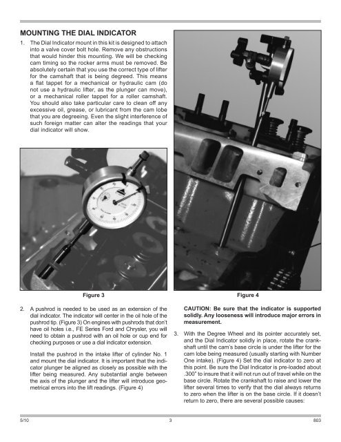
MOUNTING THE DIAL INDICATOR1. The Dial Indicator mount in this kit is designed to attachinto a valve cover bolt hole. Remove any obstructionsthat would hinder this mounting. We will be checkingcam timing so the rocker arms must be removed. Beabsolutely certain that you use the correct type of lifterfor the camshaft that is being degreed. This meansa flat tappet for a mechanical or hydraulic cam (donot use a hydraulic lifter, as the plunger can move),or a mechanical roller tappet for a roller camshaft.You should also take particular care to clean off anyexcessive oil, grease, or lubricant from the cam lobethat you are degreeing. Even the slight interference ofsuch foreign matter can alter the readings that yourdial indicator will show.Figure 3 Figure 42. A pushrod is needed to be used as an extension of thedial indicator. The indicator will center in the oil hole of thepushrod tip. (Figure 3) On engines with pushrods that don’thave oil holes i.e., FE Series Ford and Chrysler, you willneed to obtain a pushrod with an oil hole or cup end forchecking purposes or use a dial indicator extension.Install the pushrod in the intake lifter of cylinder No. 1and mount the dial indicator. It is important that the indicatorplunger be aligned as closely as possible with thelifter being measured. Any substantial angle betweenthe axis of the plunger and the lifter will introduce geometricalerrors into the lift readings. (Figure 4)CAUTION: Be sure that the indicator is supportedsolidly. Any looseness will introduce major errors inmeasurement.3. With the Degree Wheel and its pointer accurately set,and the Dial Indicator solidly in place, rotate the crankshaftuntil the cam’s base circle is under the lifter for thecam lobe being measured (usually starting with NumberOne intake). (Figure 4) Set the dial indicator to zero atthis point. Be sure the Dial Indicator is pre-loaded about.300” to insure that it will not run out of travel while on thebase circle. Rotate the crankshaft to raise and lower thelifter several times to verify that the dial always returnsto zero when the lifter is on the base circle. If it doesn’treturn to zero, there are several possible causes:5/10 3803