CE TEST REPORT
CE TEST REPORT
CE TEST REPORT
- No tags were found...

You also want an ePaper? Increase the reach of your titles
YUMPU automatically turns print PDFs into web optimized ePapers that Google loves.
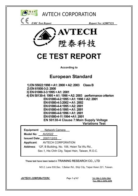
AVTECH CORPORATIONEMC Test ReportReport No: A2007121<strong>CE</strong> <strong>TEST</strong> <strong>REPORT</strong>According toEuropean Standard1) EN 55022:1998 + A1: 2000 + A2: 2003 Class B2) EN 61000-3-2: 20003) EN 61000-3-3:1995 + A1: 20014) EN 50130-4: 1995 + A1: 1998 + A2: 2003 performance criterionEN 61000-4-2:1995 + A1: 1998 + A2: 2001EN 61000-4-3:2002 + A1: 2002EN 61000-4-4:1995 + A2: 2001EN 61000-4-5:1995 + A1: 2001EN 61000-4-6:1996 + A1: 2001EN 61000-4-11:1994 +A1: 2001EN 50130-4 Clause 7:Main Supply VoltageVariations TestEquipment: Network CameraModel No: AVI202ZIssued Date: 2007/12/03Applicant: AVTECH CORPORATIONAddress: 12F, B Building, No. 106, Hsien Tai Wu Rd.,Sec.1, His Chih City, Taipei Hsin, Taiwan, R.O.C.These test have been tested in TRAINING RESEARCH CO., LTDNO.2, Lane 530,Sec. 1,Balian Rd., Shijr City, Taipei Hsien 221, Taiwan.AVTECH CORPORATION Page 1 of 62 Tel: 886-2-2696-2866Fax: 886-2-2696-2690
AVTECH CORPORATIONEMC Test ReportReport No: A2007121Table of Contents<strong>CE</strong> <strong>TEST</strong> <strong>REPORT</strong> VERIFICATION…………………………………………………………………4<strong>TEST</strong> <strong>REPORT</strong> VERIFICATION1. General Information……………………………………………………………………………… 51.1 Applicant.1.2 Manufacturer1.3 Description of EUT2. Operating Condition of EUT ……………………………………………………………………82.1 Standard for Methods of Measurement2.2 Test Method3. Test Software Used………………………………………………………………………………94. Support Equipment Used………………………………………………………………………95. Conducted Emission Test………………………………………………………………………105.1 Description of Major Test Instruments5.2 Test Procedures5.3 Test Setup Layout of Conducted Main Ports5.4 Test Result of Conducted Emission5.5 Photographs of Conducted Emission6. Radiated Emission Test…………………………………………………………………………156.1 Description of Major Test Instruments6.2 Test Procedures6.3 Test Setup Layout of Radiated Emission6.4 Test Result of Radiated Emission6.5 Photographs of Radiated Emission Test7. Harmonics Current Test ………………………………………………………………………197.1 Description of Major Test Instruments7.2 Flow-chart for Determining Conformity7.3 Harmonics current Test Setup7.4 Test Result of Harmonics Current8. Voltage Fluctuations and Flicker Test ………………………………………………………238.1 Description of Major Test Instrument8.2 Voltage Fluctuations and Flicker Test Limits8.3 Test Setup Layout of Voltage Fluctuation and Flicker8.4 Test Result of Voltage Fluctuation and Flicker9. Electrostatic Discharge Test …………………………………………………………………269.1 Description of Test Instrument.9.2 Test Procedure9.3 Typical Test Setup Layout of ESD Test9.4 Test Result of Electrostatic Discharge9.5 Photographs of Electrostatic Discharge TestAVTECH CORPORATION Page 2 of 62 Tel: 886-2-2696-2866Fax: 886-2-2696-2690
AVTECH CORPORATIONEMC Test ReportReport No: A200712110. Radio Frequency Electromagnetic Field Test …………………………………………3210.1 Description of Test Instruments.10.2 Test Procedures10.3 Typical Test Setup Layout of Radio-Frequency Electromagnetic Field10.4 Test Result of Radio-Frequency Electromagnetic Field10.5 Photographs of Radio-Frequency Electromagnetic Field Test11. Fast Transient Burst Test……………………………………………………………………3611.1 Description of Major Test Instruments11.2 Test Procedures11.3 Typical Test Setup Layout of Fast Transient Burst11.4 Test Result of Fast Transient Burst.11.5 Photographs of Fast Transient Burst Test12. Surge Immunity Test…………………………………………………………………………4012.1 Description of Major Test Instruments12.2 Test Procedures12.3 Typical Test Setup Layout of Surge Immunity12.4 Test Result of Surge Immunity12.5 Photographs of Surge Immunity Test13. Conducted Disturbances Induced by Electromagnetic Field…………………………4413.1 Description of Major Instruments13.2 Test Procedures13.3 Test Setup of Conducted Disturbances Induced by Electromagnetic Fields13.4Test Result of Conducted Disturbances Induced by Electromagnetic Fields13.5 Photographs of Conducted Disturbances Induced by Electromagnetic Fields Test14. Main Supply Voltage Dips and Short Interruptions………………………………………4914.1 Description of Major Test Instruments14.2 Test Procedures14.3 Typical Test Setup Layout of Mains Supply Voltage Dips and Short Interruptions14.4 Test Result of Mains Supply Voltage Dips and Short Interruptions14.5 Photographs of Mains Supply Voltage Dips and Short Interruptions15. EN 50130-4 Clause 7 Mains Supply Voltage Variations Test……………………………5415.1 Clause 7 Main Supply Voltage Variations Tests Description.15.2 Test Result of Clause 7 Main Supply Voltage Variations Tests Description16. EUT Photographs………………………………………………………………………………56AVTECH CORPORATION Page 3 of 62 Tel: 886-2-2696-2866Fax: 886-2-2696-2690
AVTECH CORPORATIONEMC Test Report1. General InformationReport No: A20071211.1 Applicant:AVTECH CORPORATION10F, E Building, No. 19-11,San Chung Rd.,Nankang, Taipei, 115, Taiwan, R.O.C.1.2 Manufacturer:AVTECH CORPORATION10F, E Building, No. 19-11,San Chung Rd.,Nankang, Taipei, 115, Taiwan, R.O.C.AVTECH CORPORATION Page 5 of 62 Tel: 886-2-2696-2866Fax: 886-2-2696-2690
AVTECH CORPORATIONEMC Test Report1.3 Description of EUT:Report No: A2007121EquipmentModel NoTrade NameLAN PortLAN SpeedSupported ProtocolsFrame RateNetwork CameraAVI202ZAVTECHYES10/100 Based-T EthernetDDNS, PPPoE, DHCP, NTP, SNTP, TCP/IP, ICMP, SMTP,FTP, HTTP, RTP, RTSPNTSC:30, PAL:25Number of Online Users 10SecurityWeb management softwareVideo CompressionVideo Remote ControlVideo AdjustmentAudio CompressionAudio InputAudio OutputImage SensorPixelsMultiple user access levels with passwordYES (Control up to 16 network cameras simultaneously)MPEG4 / MJPEGYESBrightness, Contrast, Saturation and HueuLaw , 128kbpsBuilt-in Microphone, External Microphone InputYES1/3.6" Image Sensor738(H)X480(V)Lens f3.6F-number F2.0Viewing Angle 80°Shutter SpeedIR LEDMin IlluminationVideo OutputBLCWhite BalanceRemote ControlMotion DetectionGeneral I/O1 / 60 (1/50) to 1 / 100,000 sec.YES1 Lux / F2.0; 0 Lux (10m IR ON)1.0 Vp-p. 75 ΩAUTOATWYESYESAlarm in x1AVTECH CORPORATION Page 6 of 62 Tel: 886-2-2696-2866Fax: 886-2-2696-2690
AVTECH CORPORATIONEMC Test ReportAlarm and eventNotificationImage upload over FTP, email and HTTPReport No: A2007121Power 12VDC, 0.5AOperating Temperature 0~40℃Humidity 85%Minimum Web browsingrequirementsDimensionIn/Out Door UsePentium 4 CPU 1.3 GHz or higher, or equivalent AMD256 MB RAM, AGP graphics card , Direct Draw, 32MB RAMWindows XP, Windows 2000 Server, DirectX 9.0 or laterInternet Exploerer 6.x or later158x40.2x115.2 mmIndoorLI TONE ELECTRONICS CO., LTDMODEL : LTE12W-S2-TAdapterINPUT : 100-240V /47 – 63HZ / 1AOUTPUT : 12V /1A /12W MAX* This specification is subject to change without notice.AVTECH CORPORATION Page 7 of 62 Tel: 886-2-2696-2866Fax: 886-2-2696-2690
AVTECH CORPORATIONEMC Test ReportReport No: A20071212. Operating Condition of EUT2.1 Standard for Methods of MeasurementEMI Test:European Standard EN 55022: Conduction and Radiation Test.European Standard EN 61000-3-2: Harmonics Test.European Standard EN 61000-3-3: Voltage Fluctuations Test.EMS Test: European Standard EN 50130-4(EN 61000-4-2: ESD, EN 61000-4-3: RS, EN 61000-4-4: EFT,EN 61000-4-5: SURGE, EN 61000-4-6: CS, EN 61000-4-11: DIPS,EN 50130-4 Clause 7:Main Supply Voltage Variations Test)2.2 Test MethodTest Configuration:Connections:According to the major function designed, the EUT video data outputs was connected toTV far-end. Via a 10m-length data cable connected to the LAN Port of the PC far-end. Audioout was connected a earphone. Power pin was connected to AC-DC adaptor (DC12V). Thetest was carried Out on EUT operational condition and the worst-case test result wasrecorded and provided in this report. The test voltage is 230Vac/50Hz.AVTECH CORPORATION Page 8 of 62 Tel: 886-2-2696-2866Fax: 886-2-2696-2690
AVTECH CORPORATIONEMC Test ReportReport No: A2007121Conducted emission test:The system was setup with the full function working. The power line conducted EMI testswere run on the line and neutral conductors of the power cord and the results were recorded.The effect of varying the position of the interface cables has been investigated to find theworst-case configuration that produces maximum emission. At the frequencies where the peakvalues of the emission exceeded the quasi-peak limit, the emission was also measured withthe quasi-peak detectors. The average detector also measured the emission either (A)quasi-peak value was under quasi-peak limit but exceeded average limit, or (B) peak valueswere under quasi-peak limit but exceeded average limit.Radiated emission test:Varying the height of antenna and then rotating the turntable found the maximum readings.Both polarization of antenna, horizontal and vertical, are measured. The effect of varying theposition of the interface cables has been investigated to find the configuration that producesmaximum emission. The highest emissions were also analyzed in details by operating thespectrum analyzer in fixed tuned quasi-peak mode to determine the precise amplitude of theemissions.3. Test Software UsedAVTECH Network AP.4. Support Equipment UsedNO Equipment Model No:Serial FCC TradeNo: ID: nameData cable1 Monitor PVM-14M4U 2019909 N/A SONY BNC-cable2 PC DD281A-AB0TW31720157<strong>CE</strong> HP Non-shieldedPower Core1.79m/noferrite core2.33m/noferrite coreAVTECH CORPORATION Page 9 of 62 Tel: 886-2-2696-2866Fax: 886-2-2696-2690
AVTECH CORPORATIONEMC Test Report5. Conducted Emission TestReport No: A2007121Test Standard: EN 55022:1998 / A1: 2000 / A2: 2003. Conducted Emissions were measured from 150kHz to 30 MHz. The EUT was placed on a wooden table that is 0.8 meters above theconducting ground plane, is placed 40 cm from the back-wall that is a vertical conducting plane.One LISN is for EUT; the other is for support equipment. The interface cables and equipmentpositioning were varied within limits of reasonable applications to determine the positionproducing maximum conducted emissions.5.1 Description of Major Test InstrumentsNO Instrument Model No. Brand Serial No.1 Receiver SCR3102 SCHAFFNER 0122 LISN (EUT) 3825/2 EMCO 9411-22843 LISN (Support) 3825/2 EMCO 9210-20074 Line switch box CB-01 TRC 98-045 FTB-1-6 Attenuator 15542 Mini-circuits 9620 036 20dB Attenuator CAT-20 Mini-circuits 9620 137 Coaxial Cable BNC3200B-0058 Jyebao CL-058 Coaxial Cable BNC31VB-0316 Jyebao IF-01ca0069-0369 50ohm terminator 370BNM NARDA PWR5W10 50ohm terminator 370BNM NARDA PWR5W11 50ohm terminator 370BNM NARDA PWR5W12 50ohm terminator 370BNM NARDA PWR5WAVTECH CORPORATION Page 10 of 62 Tel: 886-2-2696-2866Fax: 886-2-2696-2690
AVTECH CORPORATIONEMC Test Report5.2 Test ProceduresReport No: A20071211. The EUT was placed on a desk 0.8 meters height from the metal ground plane and 0.4meter from the conducting wall.2. The EUT’s LISN connect a line switch box to select L1 or L2, and then connect to apreamplifier and spectrum for pretest.3. All the support units are connect to the other LISN.4. Both sides of AC line were checked for maximum conducted interference.5. The frequency range from 150 kHz to 30 MHz was searched.6. There are more than 6 highest emissions relative to recorded. The plot is kept as theoriginal data, not included in test report.7. The detector measured the quasi-peak and average value.5.3 Typical Test Setup Layout of Conducted EmissionAVTECH CORPORATION Page 11 of 62 Tel: 886-2-2696-2866Fax: 886-2-2696-2690
AVTECH CORPORATIONEMC Test Report5.4 Test Result of Conducted EmissionTest Information:Model NO: AVI202ZFrequency Range of Test: from 0.15 MHz to 30 MHzTemperature: 25°CRelative Humidity: 64 %Power: 230V / 50HzTest Result: PASSReport No: A2007121Conducted Emission Test Data:1. AC Main Ports:Line1:Reading AmplitudeLimitMarginFrequencyPeak Quasi-Peak Average Quasi-Peak Average(dB)(KHz)(dBuV) (dBuV) (dBuV) (dBuV) (dBuV)QP / AV0.152 57.32 55.89 48.84 66.00 56.00 -10.11 / -7.160.265 50.82 **.** **.** 62.72 52.72 -1.900.320 47.94 **.** **.** 61.14 51.14 -3.200.619 47.51 43.74 35.23 56.00 46.00 -12.26 / -10.770.983 45.46 42.64 34.77 56.00 46.00 -13.36 / -11.237.648 42.86 **.** **.** 60.00 50.00 -7.14*The reading amplitudes are all under limit.AVTECH CORPORATION Page 12 of 62 Tel: 886-2-2696-2866Fax: 886-2-2696-2690
AVTECH CORPORATIONEMC Test ReportReport No: A2007121Line2:Reading AmplitudeLimitMarginFrequency(KHz)Peak Quasi-Peak(dBuV) (dBuV)Average(dBuV)Quasi-Peak(dBuV)Average(dBuV)(dB)QP / AV0.151 57.68 55.33 48.29 66.00 56.00 -10.67 / -7.710.257 51.47 **.** **.** 62.93 52.93 -1.470.320 49.16 **.** **.** 61.14 51.14 -1.980.601 46.32 43.84 35.31 56.00 46.00 -12.16 / -10.691.012 44.27 **.** **.** 56.00 46.00 -1.737.648 41.95 **.** **.** 60.00 50.00 -8.05*The reading amplitudes are all under limit.2. Communication Port:LAN:(ISN)Reading AmplitudeLimitMarginFrequency(KHz)Peak Quasi-Peak(dBuV) (dBuV)Average(dBuV)Quasi-Peak(dBuV)Average(dBuV)QP/AV(dB)1.023 47.85 **** **** 74.00 64.00 -16.153.952 49.16 **** **** 74.00 64.00 -14.845.296 51.24 **** **** 74.00 64.00 -12.767.920 55.93 **** **** 84.00 74.00 -18.0723.120 64.48 **** **** 84.00 74.00 -9.5228.700 59.75 **** **** 84.00 74.00 -14.25* The reading amplitudes are all under limit.AVTECH CORPORATION Page 13 of 62 Tel: 886-2-2696-2866Fax: 886-2-2696-2690
AVTECH CORPORATIONEMC Test ReportReport No: A20071215.5 Photographs of Conducted Emission TestAVTECH CORPORATION Page 14 of 62 Tel: 886-2-2696-2866Fax: 886-2-2696-2690
AVTECH CORPORATIONEMC Test ReportReport No: A20071216. Radiated Emission TestTest Standard: EN 55022:1998 / A1: 2000 / A2: 2003. Radiated emissions from 30 MHz to 1000 MHzwere measured with a bandwidth of 120 kHz according to the methods defines in EuropeanStandard EN 55022. The EUT was placed on a nonmetallic stand in the open-field site, 0.8meter above the ground plane. The interface cables and equipment positions were variedwithin limits of reasonable applications to determine the positions producing maximumradiated emissions.6.1 Description of Major Test InstrumentsNO Instrument Model No. Brand Serial No.1 Receiver SCR3102 SCHAFFNER 0122 Control Box TWR95-4 TRC C9001-23 Antenna CBL6141A SCHAFFNER 42064 Pre-amplifier TRC-CB-2 TRC CB-0025 Coaxial Cable (20m) RG-214/U Jyebao CL-0026 Coaxial Cable (50cm) BNC31VB-0316 Jyebao CL-0027 Coaxial Cable (20cm) BNC31VB-0318 Jyebao CL-0078 Coaxial Cable (55cm) BNC31VB-0316 Jyebao CL-0069 Coaxial Cable (55cm) BNC31VB-0316 Jyebao CL-005AVTECH CORPORATION Page 15 of 62 Tel: 886-2-2696-2866Fax: 886-2-2696-2690
AVTECH CORPORATIONEMC Test ReportReport No: A20071216.2 Test Procedures1. The EUT was placed on a turntable table 0.8 meters above ground.2. The EUT was set 10 meters from the interference-receiving antenna, which was mountedon the top of a variable height antenna tower.3. The table was rotated 360 degrees to determine the position of the highest radiation.4. The antenna is a half wave dipole and its height is varied between one meter and fourmeters above ground to find the maximum value of the field strength both horizontalpolarization and vertical polarization of the antenna are set to make the measurement.5. For each suspected emission the EUT was arranged to its worst case and then tune theantenna tower (from 1 M to 4 M) and turn table (from 0 degree to 360 degrees) to findthe maximum reading.6. Each frequency found during pre-scan measurements was re-examined and investigatedusing Quasi-Peak detector. The detector function was set to CISPR Quasi-Peak modeand the bandwidth of the receiver was set to 120KHz.7. BNC cable was fitted with ferrite clamps on the floor at the point where the cable reachesthe floor and then routed to the place where they leave the turntable.6.3 Test Setup Layout of Radiated EmissionAVTECH CORPORATION Page 16 of 62 Tel: 886-2-2696-2866Fax: 886-2-2696-2690
AVTECH CORPORATIONEMC Test Report6.4 Test Result of Radiated EmissionTest Information:Model NO: AVI202ZFrequency Range of Test: from 30 MHz to 1000 MHzTemperature: 30°CRelative Humidity: 64 %BNC cable was fitted with ferrite clamps.Report No: A2007121Test Result: PASSRadiated Emission Test Data:FrequencyReadingAmplitudeAnt.HeightTableCorrection CorrectionFactors AmplitudeLimitMarginMHz dBuV/m m degree dB dBuV/m dBuV/m dB(Horizontal)250.0251 31.59 3.97 279 -4.44 27.15 37.00 -9.85324.0240 30.62 1.88 0 -1.55 29.07 37.00 -7.93432.0250 28.75 2.54 272 1.72 30.47 37.00 -6.53756.0490 24.98 1.01 0 8.81 33.79 37.00 -3.21864.0605 21.73 3.96 238 9.65 31.38 37.00 -5.62*The correction amplitudes are all under limit.(Vertical)125.0058 26.03 1.83 265 -5.55 20.48 30.00 -9.52162.0120 28.37 0.99 18 -4.05 24.32 30.00 -5.68250.0251 38.74 1.00 244 -4.44 34.30 37.00 -2.70324.0240 32.44 1.00 96 -1.55 30.89 37.00 -6.11648.0480 20.90 0.98 237 6.64 27.54 37.00 -9.46*The correction amplitudes are all under limit.Note:1. Correction Factor means Antenna factor + Cable loss – Amplifier.2. Margin = Corrected Amplitude – Limit.3. Peak Amplitude + Correction Factor = Corrected Amplitude.AVTECH CORPORATION Page 17 of 62 Tel: 886-2-2696-2866Fax: 886-2-2696-2690
AVTECH CORPORATIONEMC Test ReportReport No: A20071216.5 Photographs of Radiated Emission TestAVTECH CORPORATION Page 18 of 62 Tel: 886-2-2696-2866Fax: 886-2-2696-2690
AVTECH CORPORATIONEMC Test ReportReport No: A20071217. Harmonics Current TestTest Standard: EN 61000-3-2: 2000. The objective of this standard is to set limits for harmonicemissions of equipment within its scope, so that, with due allowance for the emission fromother equipment, compliance with the limits ensures that harmonic disturbance levels do notexceed the compatibility levels defined in IEC 61000-2-2.For the purpose of harmonic current limitation, equipment is classified as follows:Class A:- Balanced three-phase equipment;- Household appliances excluding equipment identified as Class D;- Tools excluding portable tools;- Dimmers for incandescent lamps;- Audio equipment.Equipment not specified in one of the three other classes should be considered as Class Aequipment.Note1: Equipment that can be shown to have a significant effect on the supply system may bereclassified in a future edition of the standard. Factors to be taken into account include:- Number in use;- Duration of use;- Simultaneity of use;- Power consumption;- Harmonic spectrum, including phase.Class B: Portable tools.- Portable tools;- Arc welding equipment, which is not professional equipment.Class C:- Lighting equipment.Class D:Equipment having a specified power according to 6.2.2 less than or equal to 600W, of thefollowing types:- Personal computers and personal computer monitors;- Television receivers.AVTECH CORPORATION Page 19 of 62 Tel: 886-2-2696-2866Fax: 886-2-2696-2690
AVTECH CORPORATIONEMC Test Report7.1 Description of Major Test InstrumentsReport No: A2007121NO Equipment Model No. Serial No.1 Harmonic/Flicker Test System HP 6842A 3531A-001027.2 Flow-chart for determining ConformityAVTECH CORPORATION Page 20 of 62 Tel: 886-2-2696-2866Fax: 886-2-2696-2690
AVTECH CORPORATIONEMC Test Report7.3 Harmonics Current Test SetupReport No: A2007121AVTECH CORPORATION Page 21 of 62 Tel: 886-2-2696-2866Fax: 886-2-2696-2690
AVTECH CORPORATIONEMC Test Report7.4 Test Result of Harmonics Current TestTest Information:Temperature: 24 °CRelative Humidity: 56 %Line Voltage: 230 VReal Power: 5.6WFundamental Amp: 0.029ADevice Class: BTotal Number of Failures: None, Total Number of Errors: None.Report No: A2007121Test result: PASSHarmonics Current Test Data:AVTECH CORPORATION Page 22 of 62 Tel: 886-2-2696-2866Fax: 886-2-2696-2690
AVTECH CORPORATIONEMC Test ReportReport No: A20071218. Voltage Fluctuations and Flicker TestTest Standard: EN 61000-3-3:1995 / A1: 2001. The standard ensures that voltage fluctuations donot interfere with other equipment connected to the ac mains or cause incandescent lights tovisibly flicker in a way that causes an annoyance or health risk to an observer.When automatic controls cycle on and off, they cause frequent changes of toehold to thesupply. When the fluctuating load is in a branch circuit with other loads, these changes causeRMS voltage fluctuation that affects the entire load in the branch. In particular, variations involtage amplitude cause changes in the light output of any filament lamps in the branch circuit.Because the output of a filament lamp is proportional to the square of the applied voltage,changes in light intensities can be significant even for small changes in voltage.The total impedance of the test circuit, excluding the appliance under test, but including theinternal impedance of the supply source, shall be equal to the reference impedance. Thestability and tolerance of the reference impedance shall be adequate to ensure that the overallaccuracy of ±8% is achieved during the whole assessment procedure.8.1 Description of Major Test InstrumentNO Equipment Model No. Serial No.1 Harmonic/Flicker Test System HP 6842A 3531A-00102AVTECH CORPORATION Page 23 of 62 Tel: 886-2-2696-2866Fax: 886-2-2696-2690
AVTECH CORPORATIONEMC Test ReportReport No: A20071218.2 Voltage Fluctuations and Flicker Test LimitsThe limits shall be applicable to voltage fluctuations and flicker at supply terminals of theequipment under test.The following limits apply:- The value of Pst shall not be greater than 1.0;- The value of Plt shall not be greater than 0.65;- The value of d(t) during a voltage change shall not exceed 3% for more than 200ms;- The relative steady-state voltage change, dc shall not exceed 3%;- The maximum relative voltage change dmax shall not exceed 4%.8.3 Test Setup Layout of Voltage Fluctuation & FlickerAVTECH CORPORATION Page 24 of 62 Tel: 886-2-2696-2866Fax: 886-2-2696-2690
AVTECH CORPORATIONEMC Test Report8.4 Test Result of Voltage FluctuationTest information:Temperature: 24 °CRelative Humidity: 56 %RMS Voltage: 230 VReal Power: 5.6 WFrequency: 50.0HzReport No: A2007121Pst / Plt Test Limit Overrides: NONERMS Test Limit Overrides: NONETest Result: PASSVoltage Fluctuation Test Result:Total Number ofFailures/ErrorsLimitPass or failPst NONE < 1.0 PPlt NONE < 0.65 PDc NONE < 3% PDmax NONE < 4% PD(r) NONE
AVTECH CORPORATIONEMC Test ReportReport No: A20071219. Electrostatic Discharge TestTest Standard: EN 61000-4-2:1995 / A1: 1998 / A2: 2001. The test consists of the application ofelectrostatic discharges onto parts of the equipment accessible to the operator and ontocoupling plane 0.1m from the equipment. The discharges are generated by apparatusintended to simulate the capacity and discharge resistance of a human body.To demonstrate the immunity of equipment to electrostatic discharges caused by personnel,who may have become electrostatically charged, touching the equipment or other equipmentnearby.9.1 Description of Test InstrumentNO Equipment Model No. Serial No.1 NoiseKen Electrostatic Discharge Simulator ESS-100L (A) 2100C036052 NoiseKen Electrostatic Discharge Gun TC-815P 2100C03566AVTECH CORPORATION Page 26 of 62 Tel: 886-2-2696-2866Fax: 886-2-2696-2690
AVTECH CORPORATIONEMC Test Report9.2 Test ProcedureReport No: A2007121The test setup was consisting a wooden table, 0.8m high, standing on the groundreference plane. A HCP size is 1.6 m x 0.8 m was placed on the table. The EUT and cableswas isolated from the HCP by an insulating support 0.5 mm thick. The VCP size is 0.5 m x0.5 m. A ground reference plane was provided on the floor of the test site. It was a metallicsheet (copper or aluminum) of 0.25 mm, minimum thickness.The EUT was arranged and connected according to its functional requirements.Where the EUT is installed on a metal table, the table was connected to the reference planevia a cable with a 470k-ohm resister located at each end, to prevent a build-up of charge.Climatic conditions shall be within the following ranges:- ambient temperature: 15℃ to 35℃;- relative humidity : 30% to 60%;- Atmospheric pressure: 86 KPa (860 mbar) to 106 KPa (1060 mbar).The test voltage shall be increased from the minimum to the selected test severity level,in order to determine any threshold of failure. The final severity level should not exceed theproduct specification value in order to avoid damage to the equipment.In the case of contact discharges, the tip of the discharge electrode shall touch the EUTbefore the discharge switch is operated.In the case of air discharges, the round discharge tip of the discharge electrode shall beapproached as fast as possible (without causing mechanical damage) to touch the EUT.After each discharge, the ESD generator (discharge electrode) shall be removed from theEUT. The generator is then retriggered for a new single discharge. This procedure shall berepeated until the discharges are completed. In the case of an air discharge test, thedischarge switch, which is used for contact discharge, shall be closed.Test programs and software shall be chosen so as to exercise all normal modes ofoperation of the EUT.AVTECH CORPORATION Page 27 of 62 Tel: 886-2-2696-2866Fax: 886-2-2696-2690
AVTECH CORPORATIONEMC Test Report9.3 Typical Test Setup Layout of ESD TestReport No: A2007121AVTECH CORPORATION Page 28 of 62 Tel: 886-2-2696-2866Fax: 886-2-2696-2690
AVTECH CORPORATIONEMC Test ReportReport No: A20071219.4 Test result of Electrostatic DischargeTest information:Temperature: 24 °CRelative Humidity: 56 %Test Voltage:(X) 2.4.6 KV contact discharge(X) 2.4.8 KV air dischargeIndirect Discharges: (X) HCP (X) VCPPolarity:(X) positive (X) NegativeNumber of discharges: (10) per point for each voltage and polarityCriteria for compliance:There shall be no damage, malfunction or change of status due to the conditioning.Flickering of an indicator during the application of the discharges is permissible, providingthat there is no residual change in the EUT or any change in outputs.Observation:There is no damage due to the conditioning. Monitor screen was flickering during theconditioning. System is recovery automatically in some serious condition (position).Test Result: CompliantDirect DischargeContact DischargeAir Discharge2KV 4KV 6KV 2KV 4KV 6KV 8KV+ - + - + - + - + - + - + -1 P P P P P P P P P P P P P P2 P P P P P P P P P P P P P P3 P P P P P P P P P P P P P P4 P P P P P P P P P P P P P P5 P P P P P P N/A N/A N/A N/A N/A N/A N/A N/A6 P P P P P P N/A N/A N/A N/A N/A N/A N/A N/A7 N/A N/A N/A N/A N/A N/A N/A N/A N/A N/A N/A N/A N/A N/A8 N/A N/A N/A N/A N/A N/A N/A N/A N/A N/A N/A N/A N/A N/A9 N/A N/A N/A N/A N/A N/A N/A N/A N/A N/A N/A N/A N/A N/A10 N/A N/A N/A N/A N/A N/A N/A N/A N/A N/A N/A N/A N/A N/AAVTECH CORPORATION Page 29 of 62 Tel: 886-2-2696-2866Fax: 886-2-2696-2690
AVTECH CORPORATIONEMC Test ReportReport No: A2007121Indirect DischargeContact DischargeAir Discharge2KV 4KV 6KV 2KV 4KV 6KV 8KV+ - + - + - + - + - + - + -1 P P P P P P P P P P P P P P2 P P P P P P P P P P P P P P3 N/A N/A N/A N/A N/A N/A N/A N/A N/A N/A N/A N/A N/A N/A4 N/A N/A N/A N/A N/A N/A N/A N/A N/A N/A N/A N/A N/A N/A5 N/A N/A N/A N/A N/A N/A N/A N/A N/A N/A N/A N/A N/A N/A6 N/A N/A N/A N/A N/A N/A N/A N/A N/A N/A N/A N/A N/A N/A7 N/A N/A N/A N/A N/A N/A N/A N/A N/A N/A N/A N/A N/A N/A8 N/A N/A N/A N/A N/A N/A N/A N/A N/A N/A N/A N/A N/A N/A9 N/A N/A N/A N/A N/A N/A N/A N/A N/A N/A N/A N/A N/A N/A10 N/A N/A N/A N/A N/A N/A N/A N/A N/A N/A N/A N/A N/A N/AComment : Performance Criteria BAVTECH CORPORATION Page 30 of 62 Tel: 886-2-2696-2866Fax: 886-2-2696-2690
AVTECH CORPORATIONEMC Test ReportReport No: A20071219.5 Photographs of Electrostatic Discharge TestESD Test points:aircontactAVTECH CORPORATION Page 31 of 62 Tel: 886-2-2696-2866Fax: 886-2-2696-2690
AVTECH CORPORATIONEMC Test ReportReport No: A200712110. Radio-Frequency Electromagnetic Field TestTest Standard: EN 61000-4-3:2002 / A1: 2002. The test consists of exposing the equipmentto electromagnetic radiation swept between 80 MHz and 2GHz. The equipment isexposed to both sinusoidal amplitude modulated and pulse modulated (switched CW)signals.To demonstrate the immunity of equipment to electromagnetic fields.10.1 Description of Test InstrumentsNO Instrument Model No. Serial No.1 Shielding Room AC5-001 N/A2 DC Power Supply GPR-3520HD A1501143 Signal Generator HP 8648D 3613A001174 Amplifier AC5-002 N/A5 Power Meter Mini-Circuits LZY-1 N/A6 Spectrum Analyzer 8594EM 3710A001987 Preamplifier AC3-002 N/A8 Isotropic Probe EMC-20 2244/ 90.20AVTECH CORPORATION Page 32 of 62 Tel: 886-2-2696-2866Fax: 886-2-2696-2690
AVTECH CORPORATIONEMC Test Report10.2 Test ProceduresReport No: A2007121The test consists of exposing the EUT to electromagnetic radiation swept between 80MHzand 2 GHz. The EUT is exposed to both sinusoidal amplitude modulated and pulsemodulated signal. The pulse-modulated exposure has been added as it has been found byexperience that some components of alarm system are particularly susceptible to pulsed orswitched signals.The measurement was performed in an anechoic chamber which is fulfilled therequirements of IEC 61000-4-3. All testing of equipment shall be performed in aconfiguration as close as possible to the installed case. Wiring shall be consistent with themanufacture’s recommended procedures.The EUT shall be subjected to the conditioning in three orientations relative to the filed,such that the electric E and magnetic H components of the filed are applied in each of threeorthogonal axes of EUT.10.3 Typical Test Setup Layout of Radio-FrequencyElectromagnetic FieldAVTECH CORPORATION Page 33 of 62 Tel: 886-2-2696-2866Fax: 886-2-2696-2690
AVTECH CORPORATIONEMC Test ReportReport No: A200712110.4 Test result of Radio-Frequency Electromagnetic FieldTest Information:Frequency Range: 80-2000 MHzModulation: 80% AM Modulation with 1KHzPulse modulation: 1Hz(0.5s ON: 0.5s OFF)Step size: < 1%Temperature: 24°CRelative Humidity: 56 %Sweep time: 3 SecondsField strength: 10 V/mCriteria for Compliance:There shall be no damage, malfunction or change of status due to the conditioning.Flickering of an indicator during the conditioning is permissible, providing that there is noresidual change in the EUT or any change in outputs.Observation: There are no damage, malfunction or change of status due to the conditioning.Monitor screen was flickering during the conditioning.Test Result: CompliantAVTECH CORPORATION Page 34 of 62 Tel: 886-2-2696-2866Fax: 886-2-2696-2690
AVTECH CORPORATIONEMC Test ReportReport No: A200712110.5 Photographs of Radio-Frequency Electromagnetic FieldTestAVTECH CORPORATION Page 35 of 62 Tel: 886-2-2696-2866Fax: 886-2-2696-2690
AVTECH CORPORATIONEMC Test ReportReport No: A200712111. Fast Transient Burst TestTest Standard: EN 61000-4-4:1995 / A2: 2001. The test consists of the injection of bursts offast transients onto the power supply and/or signal inputs and outputs of the equipment.To demonstrate the immunity of equipment to bursts of fast low energy transients whichmay be produced by relays, contactors etc, and switching inductive loads and whichmay be induced into signal and data.11.1 Description of major Test InstrumentsNO Equipment Model No. Serial No.1 BEST EMC Test Instrument BEST EMC V2.3 (-8, -9) 199918-006SC2 Induction Coil INA 701 BEST 199922-001SC11.2 Test Procedures1. In order to minimize the effect of environmental parameters on test results, the climaticconditions when test is carrying out shall comply with the following requirements:- ambient temperature: 15℃ to 35℃;- relative humidity : 25% to 75%;- Atmospheric pressure: 86 KPa (860 mbar) to 106 KPa (1060 mbar).2. In order to minimize the effect of environmental parameters on test results, theelectromagnetic environment of the laboratory shall not influence the test results.3. The test apparatus and procedure shall be as described in EN61000-4-4, using the testprocedures for type tests performed in laboratories. For wall and ceiling mountedequipment, follow the procedure for floor standing equipment, but with the equipmentarranged with its normal mounting surface 0.1m from the earth reference plane.AVTECH CORPORATION Page 36 of 62 Tel: 886-2-2696-2866Fax: 886-2-2696-2690
AVTECH CORPORATIONEMC Test ReportReport No: A200712111.3 Typical Test Setup Layout of Fast Transient BurstAVTECH CORPORATION Page 37 of 62 Tel: 886-2-2696-2866Fax: 886-2-2696-2690
AVTECH CORPORATIONEMC Test ReportReport No: A200712111.4 Test Result of Fast Transient BurstTest information:Test Voltage: AC Power line (X) 0.5KV; (X) 1KV; (X) 2KV (5KHz)Signal and Control line (X) 0.25KV; (X) 0.5KV; (X) 1KV (5KHz)Polarity: (X) Positive (X) NegativeTest Duration: (X) 1 minConnected lines: (X) Power line non-shielded(X) Signal & Control line.Number of application: (1) time for each voltage and polarityCriteria for Compliance:There shall be no damage, malfunction or change of status due to the conditioning.Flickering of an indicator during the application of the bursts is permissible, providingthat there is no residual change in the EUT or any change in outputs.Observation: There are no damage, malfunction or change of status due to the conditioning.Monitor screen was flickering during the conditioning.Test Result: CompliantTemperature: 24 degreeLast: 1 minRelative Humidity: 56 %RHRest: 60secondPulse: 5/50 nsAC Power: 230 VacBurst: 15ms/300 msVoltage \ Polarity\ Test point \ Mode \0.5KV 1KV 2KVResult+ - + - + -L P P P P P PPowerN P P P P P PLineG P P P P P PSignal Line0.25KV 0.5KV 1KVClamp Test(AV Cable & LAN cables)+ - + - + -P P P P P PAVTECH CORPORATION Page 38 of 62 Tel: 886-2-2696-2866Fax: 886-2-2696-2690
AVTECH CORPORATIONEMC Test ReportReport No: A200712111.5 Photographs of Fast Transient Burst TestPower line & signal line:AVTECH CORPORATION Page 39 of 62 Tel: 886-2-2696-2866Fax: 886-2-2696-2690
AVTECH CORPORATIONEMC Test ReportReport No: A200712112. Surge Immunity TestTest Standard: EN 61000-4-5:1995 / A1: 2001.The test consists of the injection of slow highenergy transients in the a.c. mains supply lines in both line-to-line and line-to-groundcoupling mode, and into the signal and extra low voltage supply in line-to-ground mode.To demonstrate the immunity of equipment to relatively slow high energy transients, whichmay be induced in power and signal cables from lighting strikes in the vicinity or byswitching in the power distribution system or the low voltage network, including theswitching of large capacitor batteries.12.1 Description of Major Test InstrumentsNO Equipment Model No. Serial No.1 BEST EMC Test Instrument BEST EMC V2.3 (-8, -9) 199918-006SC2 Induction Coil INA 701 BEST 199922-001SC3 KeyTek Pulsed-EMI Test SystemE103, E501B, E502B, E503,E505A, E4552A0008260~0008264,0008254AVTECH CORPORATION Page 40 of 62 Tel: 886-2-2696-2866Fax: 886-2-2696-2690
AVTECH CORPORATIONEMC Test ReportReport No: A200712112.2 Test Procedures1. The electromagnetic environment of the laboratory shall not influence the test results.2. a.c. mains power lines shall be subjected to transients injected by both line to line andline to GND coupling modes. With line to GND coupling the transients shall beinjected via a 10ohm series resistor.3. The length of the power lines between the EUT and the coupling/decoupling networkshall be no more than 2m.4. Extra low voltage and signal line shall be subjected to transients injected by line toground coupling mode only, via a 40ohm series resistor.5. To find all critical points of the duty cycle of the equipment, a sufficient number ofpositive and negative test pulses shall be applied. For acceptance test previouslyunstressed equipment shall be used to the protection devices shall be replaced.12.3 Typical Test Setup Layout of Surge ImmunityAVTECH CORPORATION Page 41 of 62 Tel: 886-2-2696-2866Fax: 886-2-2696-2690
AVTECH CORPORATIONEMC Test ReportReport No: A200712112.4 Test result of Surge ImmunityTest information:Test Voltage: AC Power line (X) 0.5KV (X) 1KV, line to line(X) 0.5KV (X) 1KV (X) 2KV, line to groundSignal line (X) 0.5KV (X) 1KV, line to groundPolarity: (X) Positive (X) NegativeTest Duration: (X) 1 min (max)Criteria for Compliance:There shall be no damage, malfunction or change of status due to the conditioning.Flickering of an indicator during the application of the bursts is permissible, providingthat there is no residual change in the EUT or any change in outputs.Observation: There are no damage, malfunction or change of status due to the conditioning.Monitor screen was flickering during the conditioning.Test Result: CompliantTemperature: 24degreeRelative Humidity: 56 %RHWaveform: 1.2*50us (8*20us)Test rate : 60 secTimes: 20/5 times/each conditionAC power: 230 Vac\ Phase\ Voltage \ Mode \ Polarity \ Result0 90 180 270a.c. mains Line + P P P P0.5KV Neutral - P P P Pa.c. mains Line + P P P P1KV Neutral - P P P PLinea.c. mains+ P P P PGround0.5KV;Neutral1KV; 2KV- P P P PGroundAV Cable0.5KV; 1KVLine + P P P PGround - P P P PLAN0.5KV; 1KVLine+ P P P P- P P P PAVTECH CORPORATION Page 42 of 62 Tel: 886-2-2696-2866Fax: 886-2-2696-2690
AVTECH CORPORATIONEMC Test Report12.5 Photographs of Surge Immunity TestReport No: A2007121Power line:AVTECH CORPORATION Page 43 of 62 Tel: 886-2-2696-2866Fax: 886-2-2696-2690
AVTECH CORPORATIONEMC Test ReportReport No: A200712113. Conducted Disturbances Induced byElectromagnetic FieldsTest Standard: EN 61000-4-6:1996 / A1: 2001.The test consists of injecting radio frequencydisturbances, in the frequency range of 150KHz to 100MHz onto the various input/outputports of the equipment. The equipment is exposed to both amplitude modulated and pulsemodulated (switch CW) signal.To demonstrate the immunity of equipment to conducted disturbances induced byelectromagnetic fields onto the field wiring.13.1 Description of Major Test InstrumentsNO Instrument Model No. Serial No.1SCHAFFNER RF-SYNTHESIZERIAMP2IFIERNSG 2070-1 10202 SCHAFFNER CDN M325 137733 SCHAFFNER CDN M216 156044 SCHAFFNER CDN T004 152305 SCHAFFNER CDN S501 151676SCHAFFNERFM-KoppelzangeKEMZ801 14301AVTECH CORPORATION Page 44 of 62 Tel: 886-2-2696-2866Fax: 886-2-2696-2690
AVTECH CORPORATIONEMC Test ReportReport No: A200712113.2 Test ProceduresThe EUT shall be placed on an insulating support, 0.1m above the ground reference plane.For table-top equipment, the ground reference plane may be placed on a table.On all cables to be tested, coupling and decoupling devices shall be inserted. The couplingand decoupling device shall be placed on the ground reference plane, marking direct contactwith it at about 0.1m to 0.3m from the EUT. The cables between the coupling and decouplingdevices and the EUT shall be as short as possible and shall not be bundled nor wrapped.Height above the ground reference plane shall be between 30mm and 50mm.If the EUT is provided with other earth terminals, they shall, when allowed, be connected to theground reference plane through the coupling and decoupling network CDN-M1, (i.e. the AEport of the CDN-M1 is then connected to the ground reference.)If the EUT is provided with a keyboard or hand-held accessory, then the artificial hand shall beplaced on this keyboard or wrapped around the accessory and connected to the groundreference plane.Auxiliary equipment (AE) required for the defined operation of the EUT according to thespecifications of the product committee, e.g. communication equipment, modem, printer,sensor, etc., as well as auxiliary equipment necessary for ensuring any data transfer andassessment of the functions, shall be connected to the EUT through coupling and decouplingdevice. However as far as possible the number of cables to be tested limited by restrictingattention to the representative functions.AVTECH CORPORATION Page 45 of 62 Tel: 886-2-2696-2866Fax: 886-2-2696-2690
AVTECH CORPORATIONEMC Test ReportReport No: A200712113.3 Test Setup of Conducted Disturbances Induced byElectromagnetic FieldsAVTECH CORPORATION Page 46 of 62 Tel: 886-2-2696-2866Fax: 886-2-2696-2690
AVTECH CORPORATIONEMC Test ReportReport No: A200712113.4 Test Result of Conducted Disturbances Induced byElectromagnetic FieldsTest Information:Test Frequency: (X) 0.15 ~ 100MHzModulation: (X) Pulse 1 Hz (0.5s On, 0.5s OFF)(X) 80% 1KHz, sinusoidalStep size: (X) 1% step sizeField strength: (X) 10VCriteria for compliance:1. at level =140dBuV(10V), there is no permanent damage or change to the EUT.2. at level=130dBuV(3V), any deterioration of the picture is so minor that thesystem could still be used.3. at level=120dBuV(1V), there is no observable deterioration of the picture.Observation: There are no damage, malfunction or change of status due to the conditioning.Monitor screen was flickering during the conditioning.Test Result: CompliantTemperature: 24 degreeRelative Humidity: 56 % RHStart: 0.15 MHz Stop : 100MHz Power : AC 230VTest PortsFrequency (MHz)RangeUo = 140dBuV10VUo = 130dBuV3VPower linea.c. powerData line (CDN test)LANData line (CDN test)AV Video0.15 ~ 100 PASS N/A0.15 ~ 100 PASS N/A0.15 ~ 100 PASS N/AAVTECH CORPORATION Page 47 of 62 Tel: 886-2-2696-2866Fax: 886-2-2696-2690
AVTECH CORPORATIONEMC Test ReportReport No: A200712113.5 Photographs of Conducted Disturbances Induced byElectromagnetic Fields Testpower port:Data Line:AVTECH CORPORATION Page 48 of 62 Tel: 886-2-2696-2866Fax: 886-2-2696-2690
AVTECH CORPORATIONEMC Test ReportReport No: A200712114. Mains Supply Voltage Dips and ShortInterruptionsTest Standard: EN 61000-4-11:1994 / A1: 2001. To demonstrate the immunity of theequipment to short duration dips (reductions) and interruptions in the a.c. mains voltage,such as those caused by load switching and operation of protection devices on themains distribution network.14.1 Description of Major Test InstrumentsNO Equipment Model No. Serial No.1 BEST EMC Test Instrument BEST EMC V2.3 (-8, -9) 199918-006SC2 Induction Coil INA 701 BEST 199922-001SCAVTECH CORPORATION Page 49 of 62 Tel: 886-2-2696-2866Fax: 886-2-2696-2690
AVTECH CORPORATIONEMC Test ReportReport No: A200712114.2 Test ProceduresVoltage dips and short interruptions are caused by faults in the network, in installations orby a sudden large change of load. In certain, two or more consecutive dips orinterruptions may occur.It is recommended that the test plan shall comprise the following items:- The type designation of the EUT;- Information on possible connections (plugs, terminals, etc.) and cables, andperipherals;- Input power port of equipment to be tested;- Representative operational modes of the EUT for the test;- Performance criteria used and defined in the technical specifications;- Operational mode (S) of equipment;- Description of the test set-upIf the actual operation signal sources are not available to the EUT, they may be simulated.For each test any degradation of performance shall be recorded.The monitoring equipment should be capable of displaying the status of the operationalmode of the EUT during and after the tests. After each group of tests a full functionalcheck shall be performed.AVTECH CORPORATION Page 50 of 62 Tel: 886-2-2696-2866Fax: 886-2-2696-2690
AVTECH CORPORATIONEMC Test ReportReport No: A200712114.3 Typical Test Setup Layout of Mains Supply Voltage Dipsand Short InterruptionsAVTECH CORPORATION Page 51 of 62 Tel: 886-2-2696-2866Fax: 886-2-2696-2690
AVTECH CORPORATIONEMC Test ReportReport No: A200712114.4 Test Result of Mains Supply Voltage Dips and ShortInterruptionsTest information:Voltage reduction: 30%Duration of reduction (No. of periods, cycles of the voltage wave): 0.5; 1; 5 & 10Number of reductions at each duration: 3Interval between reductions:>= 10 SecondsVoltage reduction: 60%Duration of reduction (No. of periods, cycles of the voltage wave): 0.5; 1; 5 & 10Number of reductions at each duration: 3Interval between reductions:>= 10 SecondsVoltage reduction: 100%Duration of reduction (No. of periods, cycles of the voltage wave): 0.5; 1; 5Number of reductions at each duration: 3Interval between reductions:>= 10 SecondsTest power: 230 VacCriteria for Compliance:There shall be no damage, malfunction or change of status due to the conditioning.Flickering of an indicator during the conditioning is permissible, providing that there is noresidual change in the EUT or any change in outputs, which could be interpreted byassociated equipment as a change.Observation: There are no damage, malfunction or change of status due to theconditioning.Test Result: CompliantVoltage reduction %Ur Duration of periods ResultDips and Short 30% 0.5; 1; 5& 10 PASSInterruptions60% 0.5; 1; 5& 10 PASS100% 0.5; 1& 5 PASSNote: 0.5 Period = 10 ms 1 Period = 20 ms5 Period = 100 ms 10 Period = 200 msAVTECH CORPORATION Page 52 of 62 Tel: 886-2-2696-2866Fax: 886-2-2696-2690
AVTECH CORPORATIONEMC Test ReportReport No: A200712114.5 Photographs of Mains Supply Voltage Dips and ShortInterruptionsAVTECH CORPORATION Page 53 of 62 Tel: 886-2-2696-2866Fax: 886-2-2696-2690
AVTECH CORPORATIONEMC Test ReportReport No: A200712115. EN 50130-4 Clause 7 Mains SupplyVoltage Variations TestThe test consists of exposing the specimen to each of the maximum and minimumpower supply conditions, for a sufficient time to obtain temperature stability, and toperform the functional test.15.1 Clause 7 Main Supply Voltage Variations TestsDescriptionTo demonstrate the ability of the equipment to function correctly over the anticipated range ofmains supply voltage conditions.Subject the specimen to each of the power supply conditions, indicated in table 1, untiltemperature stability is reached:Supply Voltage max. (Umax) Unom + 10%Supply Voltage min. (Umin) Unom - 15%Unom = Nominal mains voltage. Where provision is made to Adapt the equipment to suit anumber of nominal supply voltages (e.g. by transformer tap charging), the aboveconditioning severity shall be applied for each nominal voltage, with the equipmentsuitably adapted. For equipment which is claimed to be suitable for a range of nominalmains voltages (e.g. 220/240V) without adaptation, Umax = (Maximum Unom)+10%, andUmin = (Minimum Unom)-15%. In any case the range of Unom must include the Europeannominal main voltage of 230V.AVTECH CORPORATION Page 54 of 62 Tel: 886-2-2696-2866Fax: 886-2-2696-2690
AVTECH CORPORATIONEMC Test ReportReport No: A200712115.2 Test result of Clause 7 Main Supply Voltage VariationsTests DescriptionTest information:Model: AVI202ZSupply voltage max (Umax): Unom + 10%Supply voltage min (Umin): Unom - 15%Test voltage: 230VCriteria for compliance:There shall be no damage, malfunction or change of status due to the different supplyvoltage conditions.Observation: There are no damage, malfunction or change of status due to the differentsupply voltage.Test result: CompliantAVTECH CORPORATION Page 55 of 62 Tel: 886-2-2696-2866Fax: 886-2-2696-2690
AVTECH CORPORATIONEMC Test Report16. EUT PhotographsReport No: A2007121AVTECH CORPORATION Page 56 of 62 Tel: 886-2-2696-2866Fax: 886-2-2696-2690
AVTECH CORPORATIONEMC Test ReportReport No: A2007121AVTECH CORPORATION Page 57 of 62 Tel: 886-2-2696-2866Fax: 886-2-2696-2690
AVTECH CORPORATIONEMC Test ReportReport No: A2007121AVTECH CORPORATION Page 58 of 62 Tel: 886-2-2696-2866Fax: 886-2-2696-2690
AVTECH CORPORATIONEMC Test ReportReport No: A2007121AVTECH CORPORATION Page 59 of 62 Tel: 886-2-2696-2866Fax: 886-2-2696-2690
AVTECH CORPORATIONEMC Test ReportReport No: A2007121AVTECH CORPORATION Page 60 of 62 Tel: 886-2-2696-2866Fax: 886-2-2696-2690
AVTECH CORPORATIONEMC Test ReportReport No: A2007121AVTECH CORPORATION Page 61 of 62 Tel: 886-2-2696-2866Fax: 886-2-2696-2690
AVTECH CORPORATIONEMC Test ReportReport No: A2007121AVTECH CORPORATION Page 62 of 62 Tel: 886-2-2696-2866Fax: 886-2-2696-2690