REAL TIME DVR
REAL TIME DVR
REAL TIME DVR
- No tags were found...

You also want an ePaper? Increase the reach of your titles
YUMPU automatically turns print PDFs into web optimized ePapers that Google loves.
<strong>DVR</strong> User ManualCAUTION• Please read this user manual carefully to ensure that you can use the device correctly and safely• We do not warrant all the content is correct. The contents of this manual are subject to change without notice• This device should be operated only from the type of power source indicated on the marking label. The voltage of the powermust be verified before using the same. Kindly remove the cables from the power source if the device is not to be used for a longperiod of time.• Do not install this device near any heat sources such as radiators, heat registers, stoves or other devices that produce heat• Do not install this device near water. Clean only with a dry cloth• Do not block any ventilation openings and ensure proper ventilation around the machine• Do not power off the <strong>DVR</strong> when the device is functioning. The correct operation to shut down the <strong>DVR</strong> is to stop recording,use “shut-down” button from the menu, and switch off the main power.• This machine is for indoor use only. Do not expose the machine in rain or moist environment. In case any solid or liquid getinside the machine’s case, please turn off the device immediately and get it checked by a qualified technician.• Do not try to repair the device by yourself without technical aid or approval.• When this product is in use, the relevant contents of Microsoft, Apple and Google will be involved in. The pictures andscreenshots in this manual are only used to explain the usage of our product. The ownerships of trademarks, logos and otherintellectual properties related to Microsoft, Apple and Google shall belong to the above-mentioned companies.• This manual is suitable for 4/8/16-channel digital video recorders. All examples and pictures used in the manual are from16-channel <strong>DVR</strong>.
<strong>DVR</strong> User ManualTable of Contents1 Introduction ............................................................................................................................................. 11.1 <strong>DVR</strong> Introduction .............................................................................................................................................................11.2 Main Features .................................................................................................................................................................12 Hardware Installation .............................................................................................................................. 42.1 Install Hard Drive &DVD Writer........................................................................................................................................42.1.1 Install Hard Drive .........................................................................................................................................................................................42.1.2 Install DVD Writer.........................................................................................................................................................................................52.2 Front Panel Descriptions .................................................................................................................................................52.3 Rear Panel Instructions ...................................................................................................................................................62.4 Remote Controller .........................................................................................................................................................102.5 Control with Mouse........................................................................................................................................................122.5.1 Connect Mouse..........................................................................................................................................................................................122.5.2 Use Mouse.................................................................................................................................................................................................123 Basic Function Instruction ................................................................................................................... 143.1 Startup & Shutdown.......................................................................................................................................................143.1.1 Startup........................................................................................................................................................................................................143.1.2 Shutdown ...................................................................................................................................................................................................143.2 Login .............................................................................................................................................................................153.3 Live Preview ..................................................................................................................................................................153.3.1 Live Playback.............................................................................................................................................................................................164 Main Menu Setup Guide........................................................................................................................ 174.1 Basic Configuration .......................................................................................................................................................184.1.1 System.......................................................................................................................................................................................................184.1.2 Date & Time ...............................................................................................................................................................................................194.1.3 DST............................................................................................................................................................................................................194.2 Live Configuration .........................................................................................................................................................20
<strong>DVR</strong> User Manual4.2.1 Live ............................................................................................................................................................................................................204.2.2 Main Monitor ..............................................................................................................................................................................................214.2.3 Spot............................................................................................................................................................................................................214.2.4 Mask ..........................................................................................................................................................................................................224.3 Record Configuration ....................................................................................................................................................234.3.1 Enable........................................................................................................................................................................................................234.3.2 Record Bitrate ............................................................................................................................................................................................234.3.3 Time ...........................................................................................................................................................................................................244.3.4 Stamp.........................................................................................................................................................................................................244.3.5 Recycle Record..........................................................................................................................................................................................254.3.6 Snap ..........................................................................................................................................................................................................264.4 Schedule Configuration .................................................................................................................................................264.4.1 Schedule....................................................................................................................................................................................................264.4.2 Motion ........................................................................................................................................................................................................274.4.3 Sensor .......................................................................................................................................................................................................274.5 Alarm Configuration.......................................................................................................................................................284.5.1 Sensor .......................................................................................................................................................................................................284.5.2 Motion ........................................................................................................................................................................................................294.5.3 Video Loss .................................................................................................................................................................................................314.5.4 Other Alarm................................................................................................................................................................................................324.5.5 Alarm Out...................................................................................................................................................................................................324.6 Network Configuration...................................................................................................................................................334.6.1 Network......................................................................................................................................................................................................334.6.2 Sub-stream ................................................................................................................................................................................................334.6.3 Email..........................................................................................................................................................................................................344.6.4 Server ........................................................................................................................................................................................................354.6.5 Other Settings............................................................................................................................................................................................35
<strong>DVR</strong> User Manual4.7 User Management Configuration...................................................................................................................................374.8 P.T.Z Configuration ........................................................................................................................................................394.9 Advanced.......................................................................................................................................................................414.9.1 Reset .........................................................................................................................................................................................................424.9.2 Import/Export .............................................................................................................................................................................................424.9.3 Block/Allow list ...........................................................................................................................................................................................425 Search,Playback & Backup................................................................................................................ 435.1 Time Search ..................................................................................................................................................................435.2 Event Search.................................................................................................................................................................445.3 File Management...........................................................................................................................................................455.4 Search by Image ...........................................................................................................................................................465.5 Backup ..........................................................................................................................................................................476 Manage <strong>DVR</strong> .......................................................................................................................................... 476.1 Check System Information ............................................................................................................................................486.1.1 System Information ....................................................................................................................................................................................486.1.2 Event Information.......................................................................................................................................................................................486.1.3 Log Information ..........................................................................................................................................................................................486.1.4 Network Information...................................................................................................................................................................................486.1.5 Online Information......................................................................................................................................................................................486.1.6 Record Information ....................................................................................................................................................................................496.2 Manual Alarm ................................................................................................................................................................496.3 Disk Management .........................................................................................................................................................496.4 Upgrade.........................................................................................................................................................................496.5 Logoff ............................................................................................................................................................................507 Remote Surveillance ............................................................................................................................. 517.1 IE Remote Surveillance.................................................................................................................................................517.1.1 On LAN ......................................................................................................................................................................................................51
<strong>DVR</strong> User Manual7.1.2 On WAN.....................................................................................................................................................................................................517.2 Remote Surveillance through Apple PC ........................................................................................................................537.2.1 On LAN ......................................................................................................................................................................................................547.2.2 On WAN.....................................................................................................................................................................................................567.3 Remote Preview ............................................................................................................................................................577.4 Remote Playback & Backup ..........................................................................................................................................617.4.1 Remote Playback.......................................................................................................................................................................................617.4.2 Remote Backup .........................................................................................................................................................................................667.5 Remote System Configuration.......................................................................................................................................677.6 Tools .............................................................................................................................................................................687.7 Remote Information.......................................................................................................................................................688 Mobile Surveillance............................................................................................................................... 708.1 By Phones with Windows Mobile OS ............................................................................................................................708.2 By Phones with Symbian OS.........................................................................................................................................718.3 By Phones with Iphone OS............................................................................................................................................738.4 By Phones with Android OS ..........................................................................................................................................818.5 By Phones with Blackberry OS......................................................................................................................................86Appendix A FAQ....................................................................................................................................... 92Appendix B Calculate Recording Capacity ........................................................................................... 98Appendix C Compatible Devices............................................................................................................ 99Appendix D 4-CH Specifications .......................................................................................................... 101Appendix E 8-CH Specifications .......................................................................................................... 102Appendix F 16-CH Specifications......................................................................................................... 103
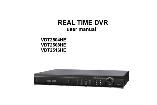
1.1 <strong>DVR</strong> Introduction<strong>DVR</strong> User Manual1 IntroductionThis model <strong>DVR</strong> (Digital Video Recorder) is designed especially for CCTV system. It adopts high performance videoprocessing chips and embedded Linux system. Meanwhile, it utilizes many most advanced technologies, such as standardH.264 with low bit rate, Dual stream, SATA interface, VGA output mouse supported, IE browser supported with full remotecontrol, mobile view(by phones), etc., which ensure its powerful functions and high stability. Due to these distinctivecharacteristics, it is widely used in banks, telecommunication, transportation, factories, warehouse, and irrigation and so on.1.2 Main FeaturesCOMPRESSION FORMAT• Standard H.264 compression with low bit rate and better image qualityLIVE SURVEILLANCE• Support HD VGA output• Support channel security by hiding live display• Display the local record state and basic information• Support USB to make full controlRECORD MEDIA• Support two SATA HDD to record for a longer time without any limitationBACKUP• Support USB 2.0 devices to backup• Support built-in SATA DVD writer to backup• Support saving recorded files with AVI standard format to a remote computer through internet1
<strong>DVR</strong> User Manual• Support 1 administrator and 63 users.• Support event log recording and checking, events unlimitedNETWORK• Support TCP/IP, DHCP, PPPoE, DDNS protocol• Support IE browser to do remote view• Support setup client connection amount• Support dual stream. Network stream is adjustable independently to fit the network bandwidth and environment.• Support picture snap and color adjustment in remote live• Support remote time and event search, and channel playback with picture snap• Support remote PTZ control with preset and auto cruise• Support remote full menu setup, changing all the <strong>DVR</strong> parameters remotely• Support mobile surveillance by smart phones , symbian, WinCE, Iphone or Gphone, 3G network available• Support CMS to manage multi devices on internet3
<strong>DVR</strong> User Manual2 Hardware InstallationNotice: Check the unit and the accessories after getting the <strong>DVR</strong>.Please don’t power up the unit till the physical installation is complete.2.1 Install Hard Drive &DVD Writer2.1.1 Install Hard DriveNotice: 1. 4-ch and 8-ch <strong>DVR</strong> connect to two SATA hard drives or one SATA hard drive plus one Writer; 16-ch <strong>DVR</strong> connectsthree SATA hard drives or two hard drives plus one DVD Writer. Please use the hard drive the manufacturersrecommend specially for security and safe field,please refer to “Appendix C Compatible Devices 3”.2. Please calculate HDD capacity according to the recording setting. Please refer to “Appendix B Calculate RecordingCapacity”.Step1: Unscrew and Open the top coverStep2: Connect the power and data cables. Place the HDD onto the bottom case as Fig 2-1.Step3: Screw the HDD as Fig 2-2.Note: For the convenience to install, please connect the power and data cables firstly, and then screw to fix.Fig 2-1 Connect HDDFig 2-2 Screw HDD4
<strong>DVR</strong> User Manual2.1.2 Install DVD WriterNotice: 1. The writers must be the compatible devices we recommend. Please refer to “Appendix C Compatible Devices”2. This device is only for backup.Step1: Unscrew and Open the top cover.Step2: Connect the power and data cables. Place the DVD writer onto the bottom case as Fig 2-3.Step3: Screw the DVD writer as Fig 2-4Fig 2-3 Connect the DVD Writer Fig 2-4 Screw the Writer2.2 Front Panel DescriptionsNotice: The front panel descriptions are only for reference; please make the object as the standard.Item Type Name Description1 Work stateindicatorPowerHDDNetBackupPlayPower indicator, when connected , the light is blueThe light turns blue when writing/ reading HDD, the light is blueThe light turns blue when it is able to access the networkThe light turns blue when backing up files and data.The light turns blue when playing video5
<strong>DVR</strong> User ManualItem Type Name Description23CompoundbuttonDigitalbutton 0/10+RECThe light turns blue when recordingMENU/+1. Enter menu in live 2. Increase the value in setupBACKUP/-1. Decrease the value in setup 2. Enter backup mode in liveRECORD/FOCUS 1. Record manually 2. FOCUS function enables at PTZ mode.REW/SPEED 1. Rewind key 2. SPEED function enables at PTZ modeSEARCH/ZOOM1. Enter search mode 2.ZOOM function enables at PTZmode.PLAY /IRIS 1. Enter play interface . IRIS function enables at PTZ modeFF/ P.T.Z.1. Fast forward 2. Enter PTZ mode in liveSTOP/ESC 1. Quit play mode 2. Exit the current interface or status1-9 Input number 1-9 or choose cameraDirection buttonInput4Multi-screenbuttonEnter button5 IR receiver IR For remote controller6 USB USB portInput number0, 10 and the above number together with otherdigital keysChange direction to select itemsChange screen display mode like1/4/9/16 channelConfirm selectionTo connect external USB devices like USB flash, USB HDD forbackup or update firmware; or connect to USB mouse2.3 Rear Panel InstructionsThe rear Panel interface for 4-ch VDT2504HE is shown as Fig 2-5:6
<strong>DVR</strong> User ManualFig 2-5 Rear Panel for 4-chItem Name Description1 P/Z Connect to speed dome2 K/B Connect to keyboard3 ALARM IN Connect to external sensor1-44 HDMI port Connect to high-definition display device (optional)5 NET Network port6 VGA port VGA output, connect to monitor7 Video out Connect to monitor8 Audio in 4 CH Audio input9 POWER switch Power on/off10 + 5V and GND +5 V and Grounding11 ALARM OUT 1-ch relay output. Connect to external alarm.12 USB portTo connect external USB devices like USB flash, USB HDDfor backup or update firmware; or connect to USB mouse13 Spot outConnect to monitor as an AUX output channel by channel.Only video display, no menu show14 Video in Video input channels from 1-415 Audio out Audio output, connect to the sound box7
<strong>DVR</strong> User ManualItem Name Description16 POWER INPUT DC12V17 FAN For cooling the deviceThe rear Panel interface for 8-ch VDT2508HE is shown as Fig 2-6:Fig 2-6 Rear Panel for 8-chItem Name Description1 P/Z Connect to speed dome2 K/B Connect to keyboard3 ALARM IN Connect to external sensor1-84 HDMI port Connect to high-definition display device (optional)5 NET Network port6 VGA port VGA output, connect to monitor7 Video out Connect to monitor8 Video in Video input channels from 1-89 Audio in 4 CH Audio input10 Power switch Power on/off11 + 5V and GND +5 V and Grounding12 ALARM OUT 1-ch relay output. Connect to external alarm.13 USB portTo connect external USB devices like USB flash, USB HDDfor backup or update firmware; or connect to USB mouse8
<strong>DVR</strong> User ManualItem Name Description14 Spot outConnect to monitor as an AUX output channel by channel.Only video display, no menu show15 Audio out Audio output, connect to the sound box16 POWER INPUT DC12V17 FAN For cooling the deviceThe rear Panel interface for 16-ch VDT2516HE is shown as Fig 2-7:Fig 2-7 Rear Panel for 16-chItem Name Description1 P/Z Connect to speed dome2 K/B Connect to keyboard3 ALARM IN Connect to external sensor1-164 HDMI port Connect to high-definition display device (optional)5 NET Network port6 VGA port VGA output, connect to monitor7 Video out Connect to monitor8 Video in Video input channels from 1-169 Audio in 4 CH Audio input10 Power Switch Power on/off11 FAN For cooling the device9
<strong>DVR</strong> User ManualItem Name Description12 + 5V and GND +5 V and Grounding13 ALARM OUT 1-ch relay output. Connect to external alarm.14 USB portTo connect external USB devices like USB flash, USB HDDfor backup or update firmware; or connect to USB mouse15 Spot outConnect to monitor as an AUX output channel by channel.Only video display, no menu show16 Audio out Audio output, connect to the sound box17 POWER INPUT DC12V2.4 Remote ControllerIt uses two AAA size batteries.• Open the battery cover of the Remote Controller.• Place batteries. Please take care of the polarity (+ and -).• Replace the battery cover.Fig 2-8 Remote Controller10
<strong>DVR</strong> User ManualItem Name Function1 Power Button Soft switch off to stop firmware running. Do it before power off.2 INFOR ButtonGet information about the <strong>DVR</strong> like firmware version, HDDinformation3 REC Button To record manually4 Digital Button Input digital or choose camera5 Multi Screen Button To choose multi screen display mode6 SEARCH Button To enter search mode7 MENU Button To enter menu8 ENTER Button To confirm the choice or setup9 Direction Button Move cursor in setup or pan/title PTZ10 +/- Button To increase or decrease the value in setup11 Playback Control Button To control playback, Fast forward/rewind/stop/single frame play12 AUDIO Button To enable audio output in live mode13 Auto Dwell Button To enter auto dwell mode14 BACKUP Button To enter backup mode15 PTZ Control Button To control PTZ camera: Move camera/zoom/focus/iris/speed controlNote: Key points to check in case the remote doesn’t work.1. Check batteries polarity.2. Check the remaining charge in the batteries.3. Check IR controller sensor for any masking.4. Check the ID of the remote with respect to the <strong>DVR</strong>.If it still doesn't work, please try using a good known remote, or contact your dealer.11
<strong>DVR</strong> User ManualThe interface of remote controller is shown in Fig 2-8 Remote Controller.Operation processes with remote controller to control multi-<strong>DVR</strong>The default device ID of the <strong>DVR</strong> is 0. It’s not necessary to reset the device ID when a remote is to be used to control a single<strong>DVR</strong>. However when controlling multiple <strong>DVR</strong>s with multiple remote controllers, you would need to configure the device ID,please refer to below steps:• Activate remote controller to control the <strong>DVR</strong>: Turn the IR sensor of the remote controller towards the IR receiver on the frontpanel, press the number key 8 twice on the remote, then input device ID of the <strong>DVR</strong> to be controlled (Range from: 0-65535;the default device ID is 0) and press ENTER to confirm.• You can check the device ID of a <strong>DVR</strong> from System SetupBasicDevice ID. You can also set multiple <strong>DVR</strong>s with the samedevice ID however this can cause interference if the <strong>DVR</strong>s are kept close to each other.2.5 Control with Mouse2.5.1 Connect MouseIt supports USB mouse through the ports on the rear panel.Notice: If mouse is not detected or doesn't work, check below steps:1. Make sure the mouse is plugged in the USB mouse port not the USB port on the front panel.2. Try with a good know mouse.2.5.2 Use MouseDuring live:Double-click on any camera window for the full screen mode. Double-click again to return to the previous screen mode.Right click to reveal the control menu on the screen. Right click to hide the control menu.12
<strong>DVR</strong> User ManualIn Configuration:Click to enter a particular option. Right click to cancel the option or to return to the previous menu.In order to input a value in a particular screen, move cursor to the input box and click. An input window will appear as Fig 2-9. Itsupports digits, alphabets and symbols as inputs. Click Shift button to input Capital letters and symbols; click Shift button againto return.You can change some values using the mouse wheel, such as time. Move cursor onto the value and roll the wheel when thevalue blinks.Fig 2-9 Digital Numbers and Letters Input WindowIt supports mouse drag. For e.g. setting up motion detection area, click customized, hold down the left button and drag to setmotion detection area.Setting up Schedule: hold left button and drag to set schedule time.In Playback:Click to choose the options. Right click to return to live mode.In Backup:Click to choose the options. Right click to return to previous picture.In PTZ Control:13
<strong>DVR</strong> User ManualClick left button to choose the buttons to control the PTZ. Click right button to return to live.Note: Mouse is the default tool for all operations unless an exception, as indicated.3.1 Startup & Shutdown3 Basic Function InstructionPlease make sure all the connections are done properly before you power on the unit. Proper startup and shutdown are crucialto expanding the life of your <strong>DVR</strong>.3.1.1 StartupStep1: Connect with the source power.Step2: The device will boot and the power LED would turn blue.Step3 A WIZZARD window will be pop-up and show some information about time zone,time setup,network configuration,record configuration and disk management. User can setup here and refer to the concrete setup steps from the correspondingchapters. If users don’t want to setup Wizard, please click Exit button to exit.Note: This <strong>DVR</strong> can only display options on either VGA monitor or BNC monitor at a given point of time, if there is live imagedisplay without menu options then please check if there is display on other device/monitor, or long press ESC key to wait forlogin dialog box to appear. Long press ESC key can switch the output between BNC and VGA3.1.2 ShutdownYou can shut down the device by using IR remote controller and mouse.14
By IR remote controller:<strong>DVR</strong> User ManualStep1: Press Power button. This will bring up a shutdown window. The unit will shut down by clicking “OK” button.Step2: Disconnect the powerBy mouse:Step1: Enter into Menu and select “Shut Down” icon. This will take you to a shutdown window.Step2: Click OK. Then the unit will power off after a while.Step3: Disconnect the power3.2 LoginUser can login or log off the <strong>DVR</strong> system. Once logged off the user cannot do anyother operation except changing the multi-screen display.Notice: The default user name and password is “admin” and 123456”For complete operational steps for changing password, adding or deleting users,please refer to section 4.7 User Management Configuration.Fig 3-1 Login3.3 Live PreviewSymbolGreenYellowRedBlueMeaningManual recordMotion detection recordSensor Alarm recordSchedule record15
<strong>DVR</strong> User ManualFig 3-2 Live Preview Interface3.3.1 Live PlaybackClick Play button to play the record. Refer to Figure3-3. User can do complete operation by clicking the buttons onscreen.Fig 3-3 Live Playback16
<strong>DVR</strong> User Manual4 Main Menu Setup GuideRight click or press ESC button on the front panel to display the menu toolbar on the bottom of the screen. Refer to Fig 4-1:Fig 4-1 Main Menu ToolbarClick icon to select a channel and then click “ ” button to select another channel so that picture-in-picture effect willbe displayed.Dwell: Dwell means to display live images from different cameras in a sequence. The images may be displayed as a singlechannel or in a grid fashion from different cameras. Dwell mode is enabled only when the chosen display mode is not able todisplay all the available cameras.Color: If this button is enabled, you can adjust the color of live images.E-Zoom: Single channel large screen electronic amplification.Volume: Enable sound.PTZ: Click the PTZ button to control rotation position, speed and auto scan of the PTZ connected to the IP camera.Snap: Use this button to take snapshots. These pictures will automatically be saved in the HDD.Record: Click this button to start/stop recording.Playback: Click this button to playback the recorded files.User can clickbutton and drag it anywhere with the left mouse17
<strong>DVR</strong> User ManualClick Menu button to pop up a window as Fig 4-2; you can also press MENU button on the front panel or operate withremote controller to display the main menu. Clicking Setup icon will pop-up the configuration menu:Fig 4-2 System Setup4.1 Basic ConfigurationBasic configuration includes three sub menus: system, date & time and DST.4.1.1 SystemStep1: Enter into MenuSetupBasicSystem. Refer to Fig 4-3:Step2: In this interface you can setup the device name, device ID, video format, maxnetwork user, VGA resolution and language. The definitions for every parametersdisplay as below:Device Name: The name of the device as it may display on the client end or onCMS, this would help the user to recognize the device remotely.Device ID: This ID is used to map the <strong>DVR</strong> with IR remote controller and speeddome cameras.Video Format: Two modes: PAL and NTSC. User can select the video formataccording to the cameras being used.Fig 4-3 Basic Configuration-BasicPassword Check: If enabled the user would need to input the user name and the password for performing corresponding18
<strong>DVR</strong> User Manualoperations.Show System Time: If selected, displays the current time during live monitoring...Max Online Users: To set the maximum number of concurrent user logins in the <strong>DVR</strong>.Show wizard: If selected, the GUI would launch the startup wizard on every boot, allowing the user to do basic setup.VGA resolution: The resolution of live display interface, ranges from: VGA800*600, VGA1024*768, VGA1280*1024 andCVBS.Note: Switching between VGA and CVBS will change the menu output mode. Please connect to relevant monitor.Language: To setup the menu language.Note: After changing the language and video output, the device needs to login again.Logout After (Minutes): You can setup the screen interval time (30s, 60s, 180s,300s). If there is no any operation within the setting period, the device will autologout and return to the login interface.No Image When Logout: If selected, there will be no image showing when logout.4.1.2 Date & TimeStep1: Enter into MenuSetupBasicDate & Time tab. Refer to Fig 4-4:Step2: Set the date format, time format, time zone in this interface; checkmark“sync time with NTP server” to refresh NTP server date; user can also adjustsystem date manually.Step3: Click “Apply” to save the setting; click “Exit” to exit the current interface.Fig 4-4 Basic Configuration-Date & Time4.1.3 DSTStep1: Enter into MenuSetupBasicDST interface. Refer to Fig 4-5:Step2: In this interface, enable daylight saving time, time offset, mode, start & end month/week/date, etc.Step3: Click “default” button to restore default setting; click “Apply” button to save the setting; click “Exit” button to exit thecurrent interface.19
<strong>DVR</strong> User ManualFig 4-5 Basic Configuration-DST4.2 Live ConfigurationLive configuration includes four submenus: live, main monitor, spot and mask.4.2.1 LiveIn this interface, user can setup camera name, adjust colors: brightness, hue, saturation and contrast.Step1: Enter into MenuSetupLiveLive tab. Refer to Fig 4-6:Note: A soft keyboard will pop up by clicking the camera name. User can self-define the camera name.Step2: For a particular camera/channel setting, please click “setting” button to see a window as Fig 4-7:Step3: In this tab, user can adjust brightness, hue, saturation and contrast in live; click “default” button to restore default setting,click “OK” button to save the setting.Step4: Select “All” to setup all channels with the same parameters.20
<strong>DVR</strong> User ManualFig 4-6 Live ConfigurationLive4.2.2 Main MonitorStep1: Enter into MenuSetupLiveMain Monitor tab. Refer to Fig 4-8:Step2: Select split mode: 1×1, 2×2, 2×3, 3×3, 4×4 and channel. Clickbutton to setup the previous channel group. Click button to set thelatter channel group.Step3: Set the dwell time.Step4: Click “default” to restore default setting; click “Apply” to save thesetting; click “Exit” to exit the current tab.Fig 4-7 Live-Color AdjustmentFig 4-8 Live Configuration-Main Monitor4.2.3 SpotStep1: Enter into MenuSetupLiveSpot tab. Refer to Fig 4-9:Step2: Select split mode: 1×1 and map the channel.Step3: Set the dwell time.Step4: Select the split mode and then setup current picture group. Click button to setup the previous channel groups ofdwell picture. Click button to set the latter channel groups of dwell picture.Step5: Click “Apply” button to save the setting; Click “Exit” button to exit the current tab.21
<strong>DVR</strong> User ManualFig 4-9 Live Configuration-Spot4.2.4 MaskYou can setup private mask area on the live image picture. For a given channel a maximum of three areas can be masked.Setup mask area: Click Setting button, enter into live image to press left mouse and drag mouse to set mask area. Pleaserefer to the below picture. Right click to exit. Click Apply button to save the setting.Delete mask area: Select a certain mask area and double click to delete that mask area. Then click Apply button to save thesetting.Fig 4-10 Live Configuration-Mask Setup Mask Area Live Image Mask Area22
<strong>DVR</strong> User Manual4.3 Record ConfigurationRecord configuration includes six sub menus: enable, record bit rate, time, recycle record, stamp and snap.4.3.1 EnableStep1: Enter into MenuSetupRecordEnable tab. Refer to Fig 4-11:ParameterRecordAudioMeaningTo enable/disable recordingfor the channelTo enable/disable audiorecording for the channelFig 4-11 Record Configuration-EnableStep2: Checkmark record and audio.Step3: Select All to setup the same settings for all channels.4.3.2 Record BitrateStep1: Enter into MenuSetupRecordRecord Bitrate tab. Refer to Fig 4-12:Step2: Setup rate, resolution, quality, encode and max bit stream.Step3: Select “All” to set same settings for all channels.Step4: Click “default” button to restore default setting; click “Apply” button to save the setting; click “Exit” button to exit thecurrent interface.23
<strong>DVR</strong> User ManualFig 4-12 Record Configuration-Record BitrateParameterRateResolutionQualityEncodeMax bitstreamMeaningRange from: 1-30(NTSC)1-25(PAL)Support CIF , HD1, D1The higher the value is, the clearerthe recorded image is. Six options:lowest, lower, low, medium, higherand highest.VBR and CBRRange from: 256kbps~2Mpbs4.3.3 TimeStep1: Enter into MenuSetupRecordTime interface. Refer toFig 4-13:Pre-alarm record time: The record time prior to actual triggering ofan alarm i.e. record time before motion detection or a sensor alarmwas triggered.Post-alarm record: Set the post recording time after the alarm isfinished, five options: 10s, 15s, 20s, 30s, 60s, 120s, 180s and 300s.Expire time: The time till which the records would be retained. If theset date is overdue, the recorded files will be deleted automatically.Step2: Select “All” to setup all channels with the same parameters.Step3: Click “Apply” to save the setting; click “Exit” to exit the current interface.Fig 4-13 Record Configuration-Time4.3.4 Stamp24
<strong>DVR</strong> User ManualStamp:This provides an option to enable or disable the Camera Name andthe Time stamp on the video. You can also choose a position for the stampon the screen.Step1: Enter into MenuSetupRecordStamp tab. Refer to Fig 4-14:Step2: Checkmark camera name and time stamp; click Setting button. Usercan use cursor to drag the camera name and time stamp at randompositions. Refer to below Figures:Step3: Select “All” to setup all channels with the same parameters.Fig 4-14 Record Configuration-StampBefore DragAfter Drag4.3.5 Recycle RecordThis option is used to recycle the HDD space once it is full. If enabled, the system will automatically delete the old records(FIFO, recycling space) and recycle the space if it is completely utilized. The setting steps are as follows:Step1: Enter into MenuSetupRecordRecycle Record tab.Step2: Checkmark the ‘recycle record’ box to activate the auto recycling.Step3: Click “Apply” button to save the setting; click “Exit” button to exit the current interface.Note: If the option is disabled or not selected, the <strong>DVR</strong> would stop recording once the HDD is full.25
<strong>DVR</strong> User Manual4.3.6 SnapIn this interface, user can set up Resolution, quality, snap interval, snap number.4.4 Schedule ConfigurationSchedule configuration includes three sub menus: schedule, motion and alarm.4.4.1 ScheduleThis tab allows defining schedule for normal recording for seven days of a week, 24 hours of a day. Every row denotes anhourly timeline for a day. Click the grid to do relevant setup. A highlighted area denotes selected timeline.Step1: Enter into MenuSetupSchedule tab. Refer to Fig 4-15.Step2: Select channel and double-click to pop up a window as Fig 4-16. Now you can edit week schedule:Click “ ” button to add a certain day schedule; click “ ” button to delete the selected schedule;Copy: Copy the specified schedule to other dates.If you want to copy the schedule settings of a channel to other or all channels, you just need to select channel and click “Copy”button.Fig 4-15 Schedule Configuration-ScheduleFig 4-16 Schedule-Week Schedule26
<strong>DVR</strong> User Manual4.4.2 MotionThis tab allows to setup schedule for motion based recording.Step1: Enter into MenuSetupScheduleMotion tab. Refer to Fig4-17:Step2: The setup steps for schedule for motion based recording aresimilar to normal schedule setup. You can refer to 4.4.1 Schedule fordetails.Note: The default schedule of motion based recording is 24x7, that is,the color of schedule settings interface is dark blue. This enables motionbased recording for 24x7. If you want to activate motion based recording,you must enable motion alarm and setup schedule for motion alarm(Refer to Chapter 4.5.2 Motion Alarm for more details).Fig 4-17 Schedule Configuration-Motion4.4.3 SensorThis tab allows to setup schedule for sensor based recording.Step1: Enter into MenuSetupScheduleSensor tab. Refer to Fig4-18:Step2: The setup steps for schedule for sensor based recording aresimilar to normal schedule setup (Refer to 4.4.1 Schedule for details).Note: The default schedule of sensor based recording is 24x7, that is,the color of schedule settings interface is dark blue. This enables sensorbased recording for 24x7. If you want to activate sensor based recording,you must enable sensor alarm and setup schedule for sensor alarm(Refer to Chapter 4.5.1 for more details).Fig 4-18 Schedule Configuration-Sensor27
<strong>DVR</strong> User Manual4.5 Alarm ConfigurationAlarm configuration includes five sub menus: sensor, motion, video loss, other alarm and alarm out.4.5.1 SensorSensor includes three sub menus: basic, alarm handling and schedule.Operate the following steps to configure sensor alarm:Step1: Enter into MenuSetupAlarmSensorBasic tab. Refer to Fig4-19:Step2: Enable channels by checking the checkboxes beside the desiredchannels.Step 3: Set the alarm type according to triggered alarm type. Two option: NOand NC.Step4: Click “Apply” button to save settings.Step5: Enter into Alarm Handling tab. Refer to Fig 4-20.Fig 4-19 Alarm configuration-Sensor-BasicSelect hold time and then click Setting button. A dialog box will pop-up as Fig 4-21:Fig 4-20 Alarm Configuration-Sensor-Alarm HandlingStep 6: Enter into alarm tab to select the options to handle alarm.Fig 4-21 Alarm Handling-Trigger28
<strong>DVR</strong> User ManualBuzzer: If selected, the local inbuilt buzzer would be activated on an alarm.Full screen alarm: If selected, there will pop up the chosen channel on the monitor on an alarm trigger.To alarm out: If selected, this would trigger the external relay output on detecting a sensor based alarm.Email: If you select this option, the <strong>DVR</strong> will send an email alert to the preconfigured email address in case of a sensor basedalarm from the particular input.Snap: If selected, the system will snap images of the checked channels on an alarm and save them in the HDD automatically.Step 7: Enter into To Record tab. Select recoding channels. It would be recorded in case of an alarm. Click OK button to savethe setting.Step 8: Enter into To PTZ tab. Set preset, cruise and track options for a PTZ in case of a sensor based alarm. Single or multiplePTZ units could be programmed to perform this function on thesame alarm.Step9: Enter into Schedule tab. Refer to Fig 4-22. The setup stepsfor schedule for sensor based alarm are similar to normalschedule setup. You can refer to Chapter 4.4.1 Schedule for moredetails. This step is very important for sensor alarm. Even if youhave enabled the sensor alarm for all channels and setup thetrigger, you will not see the result of sensor alarm if no schedule isadded.If you have set the schedule for senor based recording in thesame timeline, recordings can also be triggered.Fig 4-22 Sensor-Schedule4.5.2 MotionMotion includes two sub menus: motion and schedule.The steps to set up motion alarm are as follows:Step1: Enter into MenuSetupAlarmMotion tab. Refer to Fig 4-23:29
<strong>DVR</strong> User ManualFig 4-23 Alarm Configuration-MotionStep2: Enable motion alarm, set alarm hold time which refers to the time till which the system will wait for further detection ofmotion. Eg. If the holding time is set to 10 seconds, once the system detects a motion, it will go into alarm but would not detectany other motion alarm (specific to channel) until 30 seconds. If there is other motion detected during this period, it isconsidered it as continuous movement, otherwise it will be considered as a single motion.Step3: The setup steps of motion trigger are similar to ‘Alarm Handling’. You canrefer to Chapter 4.5.1 Sensor Alarm Handling for more details.Step4: Click “Setting” button under the Area to display the following picture asshown in Fig 4-24:Step5: In the Area tab, you can drag slide bar to set the sensitivity value (1-8).The higher the value is the more sensitive it is to motion. Since the sensitivity isinfluenced by color and time (day or night), you can adjust its value accordingto the practical conditions. Left click the grid and drag to delete area. Dragagain to add area. Click icon to set the whole area as detection area. Clickicon to clear the set detection area. Click icon to test the sensitivity asper the local conditions. Once motion is sensed, it displays a figure icon. Clickicon to save the setting. Click icon to exit the current interface. Fig 4-24 Motion-Area30
<strong>DVR</strong> User ManualNote: Prior to setting motion detection field it is recommended that youclick icon to clear the existing field and set afresh.Step6: Select “All” to setup all channels with the same parameters.Step7: Click “Apply” button to save the setting.Step 8: Enter into Schedule tab. The setup steps for schedule for motionbased alarm are similar to normal schedule setup; you can refer to 4.4.1Schedule for details. This step is very important for motion based alarm.Even if you have enabled the motion based alarm for all channels andsetup the trigger, you will not see the result of motion based alarm if noschedule is added.Fig 4-25 Motion-ScheduleIf you have set the schedule for senor based recording in the same timeline, recordings can also be triggered.4.5.3 Video LossStep1: Enter into MenuSetupAlarmVideo Loss tab. Refer to Fig4-26:Step2: The setup steps of video loss trigger are similar to alarm handling.You can refer to Chapter 4.5.1 Sensor alarm handling for more details.Step3: Click “Apply” button to save the setting; click “Exit” button to exit thecurrent interface.Fig 4-26 Video Loss31
<strong>DVR</strong> User Manual4.5.4 Other AlarmThis tab gives a choice to configure alarm for Disk Full, IP Conflict, theDisconnect event, Disk Attenuation or Disk Lost.Step1: Enter into MenuSetupOther alarm interface. Refer to Fig 4-27:Step 2: Use the dropdown menu and select the event or the alarm.Step 3: Check the required trigger options.If the selected event is “Disk Full”, then use the drop down box for “DiskShortage Alarm” to choose a threshold value for remaining HDD space. If thethreshold value is reached, the system will trigger the Disk Full Alarm.Click “Apply” to save settings; Click “Exit” to exit the current interfaceFig 4-27 Other Alarm4.5.5 Alarm OutAlarm out includes three sub menus: alarm out, schedule and buzzerTo setup alarm out:Step 1: Enter into MenuSetupAlarm out tab. Refer to Fig 4-28. Input relayname and hold time.Step 2: Select the Schedule tab. This will bring up the schedule setup interface.The setup steps for schedule for alarm out are similar to normal schedule setup;you can refer to 4.4.1 Schedule for details.This step is very important for alarm out. Even if you have enabled alarm out inthe motion based alarm or sensor based alarm, you will not see the result ofalarm out if no schedule is added here.Fig 4-28 Alarm OutBuzzerIt is an inbuilt alarm output device. To setup Buzzer:Step1: Enter into MenuSetupAlarm out Buzzer tab;Step2: Checkmark Buzzer and set buzzer alarm hold time. This would trigger the buzzer when the system is in alarm.32
<strong>DVR</strong> User Manual4.6 Network ConfigurationNetwork configuration includes five submenus: network, sub stream, Email, server and other settings. Network settings mustbe configured if <strong>DVR</strong> is used for monitoring over network.4.6.1 NetworkStep 1: Enter into MenuSetupNetworknetwork tab. Refer to Fig4-29:Step 2: HTTP port: the default value is 80. If the value changed, you need tomodify the IP address in the IE address .i.e. if HTTP port is set to 82 and IPaddress is, 192.168.0.25, then you shall input IP address ashttp://192.168.0.25:82 in IE browser.Server port: Communication port.Step 3: Connect internet. If you have a DHCP server running and would likeyour <strong>DVR</strong> to automatically obtain an IP address and other network settingsfrom that server, check the checkbox beside "Obtain an IP addressautomatically". Then the device will distribute IP address, subnet mask, andgateway IP and DNS server. If you want to configure your own settings, pleaseinput the IP address, Subnet mask, Gateway DNS server manually. You canalso check the PPOE checkbox to enable this feature and then enter usernameand password. Once the setup is completed, your <strong>DVR</strong> will automatically dialup into your network.Step 4: No matter what kinds of way to connect internet, you should test theeffectiveness of the network by clicking “Test” button after you setup thenetwork.Fig 4-29 Network Configuration-NetworkStep 5: If the network is well connected, please click “Apply” button to save settings.4.6.2 Sub-streamStep 1: Enter into MenuSetupNetwork Sub-stream tab. Refer to Fig 4-30:33
<strong>DVR</strong> User ManualStep 2: Select fps, resolution, quality, encode and max bit rateStep 3: Select “All” to setup all channels with the same parameters.ParameterFPSResolutionQualityEncodeMax BitrateMeaningRange from: 1-6 (PAL)Support CIFThe higher the value is, the clearer therecord image. Six options: lowest,lower, low, medium, higher and highest.VBR and CBRRange from: 32kbps~728kbpsFig 4-30 Network Sub-stream4.6.3 EmailStep 1: Enter into MenuSetupNetworkEmail tab. Refer to Fig 4-31:SMTP Server/Port: The name and port number of SMTP server. Check the SSLcheckbox if the server requires a secure connection (SSL); user can setup mailservers (such as Gmail) as required.Send address/password: Sender’s email address/passwordReceive address: Receiver’s email address. Here user can add at least threemail addresses. Click TEST button to test the validity of the mailbox.Attaching image: After selecting it, the system will attach images when sendingthe emails.Fig 4-31 Network Configuration-Email34
<strong>DVR</strong> User Manual4.6.4 ServerThis function is mainly used for connecting ECMS. The setting steps are as follows:Step 1: In the server tab, select “enable” as shown in the Fig 4-32.Step 2: Check the IP address and port of the transfer media server in theECMS. The default server port for auto report is 2009. If it is modified,please enter into the transfer media interface to check.Step 3: Enable the auto report in the ECMS when adding a new device.Then input the remaining information of the device in the ECMS. After that,the system will auto allot a Device ID. Please check it in the ECMS.Step 4: Input the above-mentioned server IP, server port and device ID inthe server interface .Then click “Apply” button to save settings. Now, theECMS system will automatically connect this device.Fig 4-32 Network Configuration-Server4.6.5 Other SettingsIf your <strong>DVR</strong> is setup to use PPPoE as its default network connection, you maysetup DDNS to be used in connection. The setting steps are as follows:Step 1: Select Other Settings tab. Enable DDNS server.Step2: Select DDNS server.Step 3: Input user name, password and host domain name registered in the DNSwebsite (See the following example).Step 4: Click TEST to test the effectiveness of the relevant information.Step 5: Click “Apply” button to save the settings.Note: The domain name server that selected by user is a banding domain nameof <strong>DVR</strong>. User should logon the website which provided by the server supplier toregister a user name and password firstly, and then apply for a domain name online.Once applied, user can access the server from the IE client by using that domain name.Fig 4-33 Other Settings35
<strong>DVR</strong> User ManualEnable UPnP: Select UPnP here and then enable UPnP function in your router. Therefore, there is no need for you to forwardLAN IP address and port in the router in connection of internet. After that, you can check the WAN IP address in the router.• How to apply for a domain name?Here we take www.dyndns.com for example.Step 1: Input www.dyndns.com in the IE address bar. Click ”Free Trial of DynDNS Pro””Start the trial” to register.Step 2: Input hostname, select service type and input your IP address. The picture is shown as follows:Step 3: Click “Add to cart”. Then Dynamic DNS Hosts dialog box will be displayed.Step 4: Create user account. For example, the username is “bcd”, password is “123456”.36
<strong>DVR</strong> User ManualClick” Create Account” button to create user account. After that, you shall provide your card number, card expiration andsecurity code as well as billing address. Finally click “sign up for trial” button.Now, according to the domain name registration of “DDNS”,the domain name for <strong>DVR</strong> is “abc.dyndns.tv”, username is “bcd”and password is “123456”Connect <strong>DVR</strong> via network:Step 1: Enter into Main menuNetworkother settings, checkmark DDNS, select “Dyndns” at the DDNS Sever pull down listbox and input user name and password.Step 2: Enter into configuration interface of the router to map the server port and IP address (if the user enables UPnP function,he can skip this step). Click Save button to save the settingStep 3: Login IE browser and input registered domain name “http://www.abc.dyndns.tv” to connect <strong>DVR</strong>.Definitions and descriptions of network configuration:DDNS serverDDNS serverWebsite provided by dynamic domain name supplier. The optional:www.meibu.com ,www.dyndns.com, www.no-ip.com and mintdns type.User name User name for log in the website of domain name supplierPassword Password for log in the website of domain name supplierHost domain The domain name user registered at the supplier’s website.Update interval The interval time of upgrading <strong>DVR</strong> IP address4.7 User Management ConfigurationThis tab allows you to add normal or advanced users. To add user and setup user authority:Step 1: Enter into MenuSetupUser management configuration. Refer to Fig 4-34:Step 2: Click Add button to display a dialog box as Fig 4-35:37
<strong>DVR</strong> User ManualStep 3: In General tab, input username, password and select user type. You can also check ‘Binding PC MAC Address’ andinput this address.Step 4: Click ‘OK’ button to save settings.Note: When the default value of binding PC MAC address is 0, the user is not bound with the specified computer. If the bindoption is used, the user would be able to log into the <strong>DVR</strong> only through the specific computer (carrying the MAC address).Fig 4-34 User Management ConfigurationFig 4-35 Add-GeneralStep 5: Select Authority tab and then assign the operation rights for particular user. Refer to fig 4-36.Fig 4-36 Add User-Authority38
<strong>DVR</strong> User ManualIf you want to delete the user, please select the user you want to delete in the user list box and then click “Delete” button.If you want to modify the user, please select the user you want to modify in the user list box and then click “Setup” button tomodify its general information and authority.If you want to change password of a user, please select the user in the user list box and then click “Change Password” button.4.8 P.T.Z ConfigurationP.T.Z configuration includes two submenus: serial port and advanced settings.Serial port settings are as follows:Step 1: Enter into MenuSetup P.T.Z Serial port tab. Refer to Fig 4-37:Step 2: Select “enable” and setup the value of address, baud rate and protocol according to the settings of the speed dome.Step 3: Configure all channels with the same parameters by selecting the “All” box and then doing the relevant setup.Fig 4-37 P.T.Z Configuration-Serial PortParameterAddressBaud rateProtocolSimulativeCruiseAdvance settings are as follows:Step 1: Enter into MenuSetup P.T.Z Advanced tab. Refer to Fig 4-38:Step 2: In the Advanced tab, click preset “Setting” button to see a dialog box as Fig 4-39:39MeaningThe address of the PTZ deviceBaud rate of the PTZ device. Range form: 110, 300,600, 1200, 2400, 4800, 9600, 19200, 34800, 57600,115200, 230400, 460800, 921600.Communication protocol of the PTZ device. Rangefrom: NULL, PELCOP, PELCOD, LILIN, MINKING,NEON, STAR, VIDO, DSCP, VISCA, SAMSUNG,RM110, HY, N-control.If enabled, no matter whether the PTZ device supportscruise or not, the presets will cruise.
<strong>DVR</strong> User ManualFig 4-38 P.T.Z Configuration-AdvancedFig 4-39 Advanced-PresetStep 3: In the preset setting tab, while clicking Setting button, a dialogwill pop-up as Fig 4-40:• User can control the dome by rotating up, down, left, right andadjust the rotating speed zoom, focus and iris of the dome;• Select the serial number of the preset point. Click button toenable the PTZ wiper and click button to enable the PTZ light. Fig 4-40 Preset SettingNote: PTZ must support wiper and light function and these two buttons are just available when selecting PELCOP orPELCOD.• Click Save button to save the settings, click icon to hide thetool bar, right click to view the toolbar again; click icon to exit thecurrent interface.• In the preset interface, click OK button to save the setting; click Exitbutton to exit the current interface.Step4: In the Advanced tab, while clicking cruise “Setting” button, adialog box will pop-up as Fig 4-41:Fig 4-41 Cruise Setting• Click Add button to add cruise line in the list box (max 8 cruise line can be added); select a cruise line and click Setupbutton to see a dialog box as Fig 4-42:40
<strong>DVR</strong> User Manual• Click Add icon to set the speed and time of preset point; select a preset point and then click Delete icon todelete that preset point; click Modify icon to modify the setting of a preset point. User can click icons toadjust the position of preset point. Click Preview button to preview the cruise line; click OK button to save the setting; click Exitbutton to exit the current interface.• Select a preset point in the cruise line list box. Click Delete button to delete that cruise line; click Clear all button to clear allcruise line from the list box; click OK button to save the setting; click Exit button to exit the current interface.Step5: In the Advanced tab, while clicking track “Setting” button, a dialog box will pop-up as Fig 4-43:Fig 4-42 Cruise Setting-Modify Cruise LineFig 4-43 Track Setting• User can control the dome by rotating up, down, right, left and can adjust the rotating speed and zoom, focus and iris ofthe dome; click Start Record button and move the PTZ in the required manner to record by the <strong>DVR</strong>. Click this button again canstop recording. Click Start track button to play recorded track. Click this button again can stop the playback.• Click icon to hide the tool bar and right click to view the toolbar again. Click icon to exit the current tab.Step 6: After the completion of settings, click “Apply” button to save settings.4.9 AdvancedAdvanced configuration includes three submenus: Reset, Import/Export and Block/Allow list.41
<strong>DVR</strong> User Manual4.9.1 ResetThis would reset the system to factory defaults and reboot the <strong>DVR</strong>.4.9.2 Import/ExportUser can export the data files into mobile storage devices as backup and can also import specified data files from mobilestorage device to <strong>DVR</strong>.4.9.3 Block/Allow listFig 4-44 Block/Allow ListHere authorized user can prohibit computer users within a certain IP address range from accessing <strong>DVR</strong> or allow computerusers within a certain IP address range to access <strong>DVR</strong>. For example, if an admin don’t want computer users within IP addressrange from 196.168.000.002 to 196.168.000.004 to access the <strong>DVR</strong>, he can checkmark ‘Block list’ option, and then input suchIP address range. If it is required that computer users within a certain IP address range access <strong>DVR</strong>, they can checkmark“Allow list option”, and then do the required configuration.42
<strong>DVR</strong> User Manual5 Search,Playback & BackupSearch configuration includes four submenus: time search, event search, file management and image.5.1 Time SearchStep1: Enter into MenuSearch Time search tab. Refer to Fig 5-1:Fig 5-1 Search Configuration-Time SearchStep2: Select date and channels on the right hand side and press “Search” button. A date with highlighted borderline indicatespresence of data.Step3: Set the start time by clicking a particular grid or by entering the specific value in the start time field.43
<strong>DVR</strong> User ManualStep4: Select the channel display mode and clickbutton to play record. Use the playback toolbar to control the playback.Playback buttonsNote: When the monitor resolution is set to VGA800*600, Part of the time search interface will be hidden. Click the “Expand to” button toexpand the whole interface.Click button to select channels to show live images in the playback interface. Only four channels at most can be selectedto display live images.The method of record backup during a certain period in the playback interface:Select the start time by dragging the slider and click icon. Then select the end time and click this icon again to confirm therecord period. Next, click icon to backup the record during this period.5.2 Event SearchStep1: Enter into MenuSearchEvent Search tab. Refer to Fig 5-2:44
<strong>DVR</strong> User ManualFig 5-2 Search Configuration-Event SearchStep 2: Select date and channels on the right hand side. A data with highlighted borderline indicates presence of data.Step 3: Then checkmark Motion, Sensor or All accordingly. You can search for motion based recording and sensor basedrecording.Step 4: Press “Search” button to display the searched event information in the event list box.Step 5: Double click the event item to play the record.5.3 File ManagementStep1: Enter into MenuSearchFile Management tab. Refer to Fig 5-3:Step 2: Select date and channels. The date with highlighted borderline indicates presence of data.Step 3: Press “Search” button to display the searched files in the file list box.Step 4: Use “All” button to lock/unlock or delete all files in the file management column.Step 5: Double click an unlocked item to playback.45
<strong>DVR</strong> User ManualFig 5-3 Search Configuration-File ManagementLock: Select a file and click Lock button to lock this file. Once locked, the file cannot be deleted.Unlock: Select a locked file and click Lock button to unlock this fileDelete: Select an unlocked file and click Delete button to delete this file.5.4 Search by ImageStep 1: Enter into MenuSearchImage tab.Step 2: Select data and channels on the right hand side.Step 3: Press “Search” button to search for a recorded image.Step 4: Once an alarm image has been identified, the user can double click the image to play the recording.You can lock the image by clicking “Lock” button. Click “Save” button to copy the image on the HDD. Click “Save All” to copy allimages on the HDD.Note: In order to take images on alarm, the snapshot feature should be activated in “Alarm Handling” for different kind of alarms.Please refer to 4.5 Alarm Configuration for details.46
5.5 Backup<strong>DVR</strong> User ManualThis unit supports backup by built-in SATA DVD Writer or USB flash drive. User also can make backup by IE browser viainternet. Refer to 7.3.2 Remote backup.Step1: Enter into main menu Backup interface. Refer to Fig 5-4:Fig 5-4 Backup ConfigurationStep2: Set the start & end time, select channels and click Search button to display the searched data in the data backup list boxStep3: Select a required file or checkmark “All” to select all data files. Click Backup button to display Backup informationwindow.Step4: In the backup information interface, user can check the relevant options for backing up files. These options includestorage Media, backup player and save file type. Then click Start button to start backup.Note: If the backup files are saved in <strong>DVR</strong> format, please check backup player. Only this player can play these files in <strong>DVR</strong> format. If thebackup files are saved in AVI format, you can play these files with common media player.6 Manage <strong>DVR</strong>47
<strong>DVR</strong> User Manual6.1 Check System InformationCheck system information includes six submenus: system, event, log, network, online user and record information.6.1.1 System InformationIn this tab, user can check the hardware version, MCU version, kernel version, device ID, etc.6.1.2 Event InformationIn this tab, you can search for events like motion, sensor and video loss. The utility provides an interface to have a date basedand a channel based search. This report can further be saved on a USB flash drive as an html file using the export button.6.1.3 Log InformationIn this tab, you can search for relevant logs as per the set date and event which includes operation, setup, playback, backup,search, check information and error. This report can further be saved on a USB flash drive as an html file using the exportbutton.6.1.4 Network InformationIn this tab, you can check relevant parameters of network.6.1.5 Online InformationIn this tab, you can check the details of the connected online users.Refresh: refresh the current interface.Disconnect: Disconnect the online users to access <strong>DVR</strong>. If this function is used by the admin, the particular PC will not be ableto access the device for five minutes. .48
6.1.6 Record Information<strong>DVR</strong> User ManualIn this tab, a user can check resolution, ftp and record status including sensor based recording, motion based recording,manual recording or schedule recording.6.2 Manual AlarmIn this tab, user can trigger a manual alarm.6.3 Disk Management1. Format the diskStep1: Enter into disk management tab.Note: please format the hard disk before recording. If not formatted, it will show the status of the disk-free space, and totalspace at the bottom of screen.Step2: Click Refresh button to refresh the disk information in the list box;Step3: Select a hard disk and click Format button to start format.Note: All recorded files in the hard disk will be lost once it is formatted.2. AdvancedUser may check model, S/N, firmware, health status of the disk in this interface. User also can monitor the temperature, internalcircuit, dielectric material of the disk, analysis the potential problems of the disk and warn so as to protect its data.6.4 UpgradeThe <strong>DVR</strong> can be upgraded by using USB flash drive. Get the upgrading software from your vendor when there is a newsoftware version.Upgrade Steps:49
<strong>DVR</strong> User ManualStep 1: Copy the upgrade software which gets from vendor into the USB storage deviceStep 2: Connect the USB flash drive to the USB port.Step 3: Enter MenuUpgrade tab. Then the upgrade software name would be displayed in the upgrade list box.Step 4: Select that software and then click upgrade button. It will upgrade automatically.Note: Please wait for a while when the system reboots. Never cut off power during upgrading. The original configuration will bereserved after upgrade.6.5 LogoffEnter into Menu Logoff tab. A log off dialogue box will popup. The device will log off by clicking “OK” button. If you want to login again, clickicon to enter into user name and password to re-login.50
<strong>DVR</strong> User Manual7 Remote Surveillance7.1 IE Remote SurveillanceIn order to view the <strong>DVR</strong> from a network it must be connected to a LAN/WAN or internet. The network setup should be doneaccordingly. Please refer to 4.6 Network Setup. This <strong>DVR</strong> supports IE browser, on Windows XP and Vista platform.7.1.1 On LANStep 1: Enter into the <strong>DVR</strong>’s Main MenuSetupNetwork tab to input IP address, Subnet Mask, etc .If using DHCP, pleaseenable DHCP in both the <strong>DVR</strong> and the router.Step 2: Enter Record Setup to set network video parameters like resolution, frame rate etc.Step 3: Open IE on a computer on the same network. Input the IP address of the <strong>DVR</strong> in IE address bar and press enter.Step 4: IE will download ActiveX component automatically. Enter the username and password in the subsequent windowNotice: If HTTP port is not 80, other number instead, need add the port number after IP address. For example, set HTTPport as 82, need input IP address like 192.168.0.25:82.User name and password here are the same with that used on the <strong>DVR</strong>. The default is admin and 123456.7.1.2 On WANThere are two ways for the <strong>DVR</strong> to connect to internet.1. Connect the <strong>DVR</strong> to internet through router or virtual serverStep 1: Enter into the <strong>DVR</strong>’s Main MenuSetupNetwork interface to input IP address, Subnet Mask, etc. If using DHCP,please enable DHCP in both the <strong>DVR</strong> and router.Step 2: Forward IP address and port number in Virtual Server setup of the router or virtual server (If the user has enabled theUPnP function in both the <strong>DVR</strong> and router, he can skip this step). Configure the firewall to allow accessing the <strong>DVR</strong>.Note: Port forwarding settings may be different in different routers and server. Please refer to the router’s manual for details.51
<strong>DVR</strong> User ManualStep 3: Open IE browser, input IP address, or dynamic domain name and enter. If HTTP port is not 80, add the port number afterIP address or domain name.Step 4: IE will download ActiveX automatically. Then a window pops up and asks for user name and password. Input name andpassword correctly, and enter to view.Note: If you cannot download and install ActiveX, please refer to FAQ Q8.Fig 7-1 View with IE Browser2. Connect the <strong>DVR</strong> to internet through PPPoE directly.Step 1: Enter into the <strong>DVR</strong>’s Main MenuSetupNetwork interface to enable PPPoE and then input user name and passwordreceived from your ISP. Next, click ‘Apply’. The <strong>DVR</strong> will connect to the server and would give a confirmation message.52
<strong>DVR</strong> User ManualStep 2: When accessing the remote interface of <strong>DVR</strong>, user can input WAN IP to access directly (user can enter into MainmenuInformationNetwork interface to check IP address).Step 3: If users want to utilize dynamic domain name, please apply for a domain name in a DNS server supported by the <strong>DVR</strong> orrouter. Then add to the <strong>DVR</strong> or router.Step 4: The following setting steps are as the same as Step3 and Step4 in Point 1.7.2 Remote Surveillance through Apple PCNote: Because the current plug-in version of client end just only supports 32-bit mode, so the safari browser shall start 32-bitmode. If the browser is the earlier MACOS version, the default setting is 32-bit mode and the setting can be skipped.The Setting steps are as follows:First: Right click safari icon and select “Show in Finder”.Second: Select ApplicationsRight click “Safari. App”Select “Get Info”.Third: Select “open in 32- bit mode”.53
<strong>DVR</strong> User Manual7.2.1 On LANStep 1: After starting Apple computer, click Apple icon. The following window will pop up. Please select “SystemPreferences””Internet &Wireless”click “Network”Step 2: Enter into Network interface and then click “Ethernet Connected” to check the internet connection of Apple PC.54
<strong>DVR</strong> User ManualStep 3: After acquiring the IP address, Subnet Mask and so on, please enter into the <strong>DVR</strong>’s Main MenuSetupNetworkinterface to manually input IP address, Subnet Mask and Gateway according to the configuration of PC. The network segmentshould be the same as the PC. If using DHCP, please enable DHCP in the <strong>DVR</strong> and router.Step 4: After finishing the above information, users can enter LAN IP and http port in the Safari browser. For example: inputhttp://192.168.1.100:81(here 192.168.1.100 is LAN IP of <strong>DVR</strong>, 81 is the http port of <strong>DVR</strong>). Click “ ”button, the browser willdownload Active X control as shown below:Step 5: Click icon and then select the Active X control, the welcome interface will be shown. Click “Continue””Install”55
<strong>DVR</strong> User Manualbutton,the following window will pop up:Input the name and password of Apple PC and then click “OK” to install this Active X control.Step 6: After finishing installing the Active X control, please quit from the Safari browser. Right click Safari icon on the desktopand then select “Quit” button to quit the browser. Then restart Safari browser. Input the IP address and http port to enter into thelogin interface of <strong>DVR</strong>.7.2.2 On WANThere are also two ways for <strong>DVR</strong> to connect to Internet.1. Connect the <strong>DVR</strong> to internet through router or virtual serverStep 1: The network setups are the same as step one to step four of point 1 on WAN of IE remote surveillance.Step 2: Enter WAN IP and http port in the Safari browser to install the Active control. Then a window pops up and asks for username and password. Input name and password correctly, and enter to view.2. Connect the <strong>DVR</strong> to internet directly.Step 1: The network setups are the same as step one of point 2 on WAN of IE remote surveillance.Step 2: Enter WAN IP and http port or domain name in the Safari browser to install the Active control. Then a window pops upand asks for user name and password. Input name and password correctly, and enter to view.56
<strong>DVR</strong> User Manual7.3 Remote PreviewFig 7-2 Remote Live PreviewSymbol and function Definitions:1 Channel indicator 2 Screen display mode 3 Volume4 Snapping picture 5 Start manual record 6 Start IE record7 Bidirectional talk 8 Playback 9 Color10 PTZ control 11 Master/sub stream status57
<strong>DVR</strong> User ManualNote: click button to record manual and the record file will be saved in user’s PC.Screen display mode:Click the icon beside the screen display mode,channel select dialog will appear as below:Take 8-channel view for example: user can checkmark 8channels form 1-ch to 16-ch at random to display the livepictures, A maximum of 16 channels can be selected.Then click OK button to confirm the setting.Fig 7-3 Channel Selection58
Snap picturesThe system will automatically capture pictures and save those pictures in the computer by clicking “Snap”User should set up the path for those picture in the ConfigurationLocal configuration.icon,Color adjustment:Drag the slide bar to adjust Brightness, Contrast, Hue, and Saturation. Click Default to reset them to original value.ButtonsDescriptionDrag the scroll bar to adjust the brightness of channelDrag the scroll bar to adjust the contrast of channelDrag the scroll bar to adjust the saturation of channelDrag the scroll bar to adjust the hue of channelClick this button to recover the default value of brightness,contrast, saturation and hue.Save the adjustmentPTZ controlPlease connect speed dome to the device via RS485 firstly. Make sure the protocol of the speed dome is supported by thedevice and is configured accordingly in the <strong>DVR</strong>. User can move the dome up, down, right, left and adjust rotation speed, Irisand zoom, focus and set the presets, etc.Buttons definition:ButtonsDescriptionto rotate the dome upwards. to rotate the dome diagonally up-left. to rotate thedome diagonally up-right to rotate the dome downwards. to rotate the domediagonally down-right to rotate the dome diagonally down-left to rotate the dometowards left. to rotate the dome towards right to stop rotating the dome.
<strong>DVR</strong> User ManualDrag the scroll bar to adjust rotating speed of the dome.'Iris' button. Clickbutton near 'Iris' button to increase light of the dome. Clickbutton near 'Iris' button to decrease light of the dome.'Zoom' button. Clickcamera. Clickcamera.'Focus' button. Clickbutton near 'Zoom' button to zoom in the locale picture of thisbutton near 'Zoom' button to zoom out the locale picture of thisbutton near 'Focus' button to have short focus.Go to the PresetSelect and do auto cruiseTrackAuto scanWiper buttonLight buttonClick the right mouse on the live interface to display a pull-down menu as belowbutton near 'Focus' button to have long focus. ClickFig 7-4 Right Key Sub Menu60
<strong>DVR</strong> User ManualStream: This <strong>DVR</strong> supports master stream and sub stream. Master stream has higher frame rate, max 25 fps(PAL)/30 fps(NTSC) for every channel, but it needs higher network bandwidth; second stream has low frame rate, max 6FPS (PAL)/7FPS(NTSC) for every channel, but it requires low network bandwidth as compared to the master stream. Therefore, userscan select the stream according to their bandwidth.All to master/sub stream: Set all channel to master stream or sub stream.Enable audio: Enable or disenable audioFull screen: The live preview picture will display in full screen and the tool bar will be hidden; double click left or click rightmouse to return.Zoom in: Single channel large screen electronic amplification. Click the channel which needs to be zoomed. Right click toselect zoom in button to zoom in the image. Double click or right click to exit.7.4 Remote Playback & Backup7.4.1 Remote PlaybackClick button to enter into record playback interface, refer to Fig 7-5:Select the record date and channels and double-click the file name in the record file list box. Then user can play that file andpreview the picture.61
<strong>DVR</strong> User ManualFig 7-5 Play Record File InterfaceThis <strong>DVR</strong> supports remote time search, event search and file management.By Time Search:Step1: Enter into SearchTime search. Refer to Fig 7-6:62
<strong>DVR</strong> User ManualFig 7-6 Time Search InterfaceStep2: The highlight date in the area2 indicates recorded data. Select the date in the area 2 and record channels in area3Step3: Click “Search” button. The record data will be displayed in the data information list box;Step 4: Set the Start time and display mode in the area1 as requiredStep 5: Click “play” button to playbackStep 6: Click the relevant buttons in the interface for operation, like FF, pause, change channel mode, research, etc. Pleaserefer to Fig 7-7:63
<strong>DVR</strong> User ManualBy Event Search:Step1: Enter into SearchEvent Search. Refer to Fig 7-8:Fig 7-7 Playback by Event Search64
<strong>DVR</strong> User ManualFig 7-8 Event Search InterfaceStep 2: Click the highlight date and select record channels.Step 3: Checkmark the event type: motion and sensor.Step 4: The events will be display in the event list box by clicking Search button.Step 5: Double-click certain item to playbackFile ManagementStep 1: Enter into SearchFile management. Refer to Fig 7-9:Step 2: Select highlighted date and channels.Step 3: Click “Search” button to search the recorded files.65
<strong>DVR</strong> User ManualFig 7-9 File Management InterfaceLock: Select certain file item in the file list box and then click “Lock” button to lock this file that ca not be deleted or overlaidUnlock: Select a locked file and then click “unlock” button to unlock this fileDelete: Select an unlock file and then click “delete” button to delete this file from file list7.4.2 Remote BackupClick Backup button to enter into backup interface. Refer to Fig 7-10:66
<strong>DVR</strong> User ManualFig 7-10 Remote Backup InterfaceStep1: Select channels, set the start and end time and then click “search’ button to display the file information in the file list boxStep2: Select backup files and click “browse” button to set the path. Then click “backup” button to start backup. The backupfiles will be saved on user’s PC.7.5 Remote System ConfigurationYou can do remote setup of the device which includes functions like basic configuration, live configuration, record configuration,schedule configuration, alarm configuration, network configuration, PTZ configuration and user configuration. You shouldselect an option from the menu list on the left and then setup the relative parameters. Only one user can do configuration setupat a given point of time. Click Config tab to enter into the below interface as Fig 7-11:67
<strong>DVR</strong> User ManualFig 7-11 Remote System ConfigurationThe sub menu list and the options in every menu are similar to that of the <strong>DVR</strong>. Please refer to Chapter 4 Main Menu SetupGuide for more details.7.6 ToolsClick on tool’s tab to access the disk management tool. You can view the status of the HDD, change/view the read/writeproperties and can also format the HDD remotely.7.7 Remote InformationThe Info tab provides a web based interface to access the general information pertaining to the <strong>DVR</strong>’s settings. It includes fivesubmenus: System, Event, Log, Network and Online users. The sub menu list and the options in every menu are similar to that68
<strong>DVR</strong> User Manualof the <strong>DVR</strong>. Please refer to Chapter 6 System information for more details.Fig 7-12 Remote Information SearchNote: There may be slight differences with respect to functions of remote surveillance between through IE andthrough Apple PC. Here we only take IE remote access for example.69
<strong>DVR</strong> User Manual8 Mobile SurveillanceThis <strong>DVR</strong> supports mobile surveillance by phones with Windows mobile, symbian, android, Iphone and Blackberry OS. At thesame time, it supports 3G network. We tested Dopod D600 (WM5) and Dopod S1 (WM6), which work fine with the <strong>DVR</strong>.If you want to make mobile surveillance, please enable network service on the <strong>DVR</strong> first and refer to Chapter 4.6 Networkconfiguration. The below is the use instructions on mobile client end for five OS.8.1 By Phones with Windows Mobile OSStep1: Firstly activate the network access on mobile phone and then run “Internet Explorer”. Input the server’s address andthe connection is built up shown as below picture on the left:Step2:Click on the software name. A dialog box pops up as below picture in the middle:Step3:Click “Yes” to start downloading and installing:Step4:PCam will be opened automatically after installation. Refer to the picture on the right:Step5:Input the server’s address, ID and password respectively in the field of “Server”, “User” and “Password”, and click “Go”70
<strong>DVR</strong> User Manualto log on the server. Refer to the below picture on the left:Step6:Camera 1 is the default channel after login. Change the channel in rolling-down menu of “Channel”. Refer to the belowpicture on the right:Notice: User name andpassword here are the samewith that used on the <strong>DVR</strong>.The default is admin and123456.8.2 By Phones with Symbian OSPlease use the smart phones with symbian version supported by this unit. The detail information is as follows:Symbian S40supportSymbian UIQsupportSymbian S80supportSymbian S60supportSymbian S60 3 rd Edition-Symbian OS v9.1supportSymbian S60 3 rd Edition with FP 1-Symbian OS v9.2 supportSymbian S60 3 rd Edition with FP2-Symbian OS v9.3 supportSymbian S60 5 th Edition-Symbian OS v9.4supportSymbian S60 5.1 Edition-Symbian OS v9.5supportStep1:Enable the network access on mobile phone. Then run Web browser.Step2:Input the <strong>DVR</strong> server’s IP address in a new-built bookmark. Click this bookmark to connect to the <strong>DVR</strong>. Refer to the71
<strong>DVR</strong> User Manualpicture on the left:Step3:A welcome window will pop up and requires a package. Click the software name to download. Refer to the picture onthe right:Step4:A security windows will pop up after downloading and ask if install the package. Click YES to install.Step5:A Scam shortcut icon appears on the system menu.Step6:Run Scam program. It will enter a function interface. Refer to the picture on the left:Step7:Click System setting--->Login Setting to enter login interface. Refer to the picture on the right:Step8:Input the server’s address, ID and password respectively. Then save.Notice: About Access point, there may be different access points in different countries or from service providers.72
<strong>DVR</strong> User ManualStep9:Enter Live View, it will connect the server and display pictures. Refer to the picture on the left:Notice: User name and password here are the same with that used on the <strong>DVR</strong>. The default is admin and 123456.Step10:In Live View, users can snap pictures, change channels and control PTZ. Refer to the picture on the right:8.3 By Phones with Iphone OS1. Install through Iphone.Step 1. Open App Store function of Iphone.Step 2. Enable “search” function to search “Superlive”.73
<strong>DVR</strong> User ManualStep 3: Click Superlive-pro, enter into “introduce” interface and then click “FREE”button. Now this button will change into“INSTALL”Step 4: Input iTunes Store password and then click “OK”. The software will be installed automatically.74
<strong>DVR</strong> User ManualNote: If it is the first time for user to operate, please enter user ID; if there is no Store account, user needs to apply forone.2. Install through PC.Step 1: Install iTunes store in PC and then loginStep 2: Connect iPhone and PC75
<strong>DVR</strong> User ManualStep 3: Enable “search” function to search “Superlive-Pro” Step 4: Click “free application” buttonStep 5: Input apple ID and password and then click “acquire”Step 6: Checkmark “synchronously apply program” and “Superlive-pro”, and then click “Apply” buttonOperation Instruction for Superlive-Pro1. Login interface76
<strong>DVR</strong> User ManualEnterserver’s IP address (or domain name), user name and passwordClick “Remember server” to save the setting; click button can quick input savedserveraddress, user name and password.2. Main InterfaceImage viewPlaybackSettingInformation viewServer listLogoffSingle channelFour channelSnapRecordAudioTalkColorPTZ77
<strong>DVR</strong> User ManualUpward rotates the PTZLeftward rotates the PTZStop rotating the PTZZoom Out/Focus Out/Iris SubDownward rotates the PTZRightward rotates the PTZZoom In/Focus In/Iris AddTo enter into the next interfaceTo return to the previous interface Preset select the preset pointCruise Set the cruise line Speed Rotate speed of the PTZ3. Image ViewAfter the image is snapped, you can click icon to enter into the image view interface. Select the image and click it to amplifythis image. Then you can copy or delete the image. Click ‘close’ button to return to the previous interface.78
<strong>DVR</strong> User Manual4. PlaybackClickicon to enter into the playback interface. Then click ‘Search’ button, select the time and channel to playback and clickbutton. Now you can see the local file list. Select a file and click play button to playback. You can also copy or delete thefile. Finally, click ‘Close’ button to return to the previous interface.You can also search file to playback through time search, event search and remote file search. Please click the related button.5. Server list79
<strong>DVR</strong> User ManualClickbutton to enter into server list interface. You can clickicon to add a server list. After you add the list, you can click icon toedit the server information and click icon to delete this serverinformation.6. Configuration interfaceClickbasic,stepsicon to enter into Settings interface. You can set many properties, such as local,live, record, schedule, alarm, network, etc. Please see chapter four in respect of settingfor more details.7. Information View Interface80
<strong>DVR</strong> User ManualthetheofClick icon to enter into information view interface. You can check theinformation of system, network and online users. In the system interface, you can seeinformation of device name, device ID, hardware version, MCU version and so on. Innetwork interface, you can see the information of http port, server port, IP address,gateway, network status, etc. In the online users interface, you can see the informationthe current online users.8.4 By Phones with Android OSSoftware InstallationStep 1: Run Google Market programStep 2: Search ”Supercam”81
<strong>DVR</strong> User ManualStep 3: Press “Install” buttonStep 4: Click “OK” buttonStep 5: You can view the download and install process in notifications; Once finishing downloading, the software will installautomatically.82
<strong>DVR</strong> User ManualLoginEnter into server’s IP address (or domain name), user’s ID and password.Click “Remember server” to save the setting; click button can quick input saved server address, user name and password.Main menu【Playback】 playback record file 【Image】 image view【Log】 log record 【Server List】 device list【Live】 live view 【Settings】 software setting【Information】 device information view 【Help】 software help center【Logoff】 logoff and return to login interface83
<strong>DVR</strong> User ManualLive viewStop playingScreenmodeSnapTalkSingledisplayFourdisplayPTZRecordchannelchannelsImage viewLive audioHideThe first pictureThe previous pictureNext pictureThe last pictureZoom inZoom outDelete84
<strong>DVR</strong> User ManualRecord playbackPlay/PauseStopFast forwardSlow playClick Playback icon in the Main Menu interface to enter into the playback interface. First, choose channel. Second, select therecord file and click it to playback. Finally, click ‘Return’ button to return to the previous interface.Server listAdd a server listReturnModify a server listDelete a server listReturn to the previousinterfaceConfig interface85
<strong>DVR</strong> User ManualAlarm settingStorage settingDisplay settingIf Audio alarm is enabled, when VideoLoss/Sensor/Motion happen , sound alarm will betriggered; If shake Alarm is enabled, when VideoLoss/Sensor/Motion happen , shake alarm will betriggered.User can setup the relevant parameters of mobilevideo. This function can be valid only insert SD card.User can setup display order or display mode.Information view8.5 By Phones with Blackberry OS1. Open the browser of BlackBerry phone and enter sever address86
<strong>DVR</strong> User Manual2. Click “Supercam” to link3. Click “Download” button on the popup interface and the download progress will be shown.4. Finished downloading, the software will be installed automatically.Note: If the software fails to download, please check in accordance with the following steps:1. Check whether the network of mobile phone is normal or not2. Check whether <strong>DVR</strong> server connect network normally or not3. Modify the option of Browser Configuration.(1) Enter into Menu->Option->Browser Configuration; Refer to the following figure on the left.(2) Enter into Menu->Option->Cache Operations, clear up browser cache. Refer to the below picture on the right:87
<strong>DVR</strong> User ManualNote:When user used the Supercam software in mobile phone with touch screen, there will be compatible problem.Solution: Enter into Options Menu->Advance options->Applications->Supercam and click “Disable Compatibility” button. Thisproblem will be solved.LoginEnter server’s IP address (or domain name), user’s ID and password.Click “Remember server” to save the setting; click button can quick input savedserver address, user name and password.Main interfaceImage image view Log log recordServer List device list Settings software settingLive live view Informationdevice informationviewHelpsoftware helpcenterLogofflogoff and return tologin interface88
<strong>DVR</strong> User ManualLive viewNote: User can clickReturn button on the Blackberry phone to return the previous interface.89
<strong>DVR</strong> User ManualMark 1 Current viewing channel Mark 2 Channel statusSwitch channelsSnapBackground alarmUpward rotates the PTZLeftward rotates the PTZPTZ, click to switch to Fig 2 interfaceFull screenStop rotating the PTZDownward rotates the PTZRightward rotates the PTZZoom In/Focus In/Iris AddZoom Out/Focus Out/Iris SubPreset Select the preset point Group Set the cruise lineServer list90
<strong>DVR</strong> User ManualSoftware configurationInformation view91
<strong>DVR</strong> User ManualAppendix A FAQQ1. Why the <strong>DVR</strong> doesn’t turn on even after connecting to the power?a. The power adapter could have gone bad. Please change a new power adapterb. The power from the adapter may be not enough for operating the <strong>DVR</strong>. Please use the power adaptor supplied along with the<strong>DVR</strong>.c. It could be a hardware problem.Q2. There is no menu displayed and only has live image display.a. Check whether the monitor is connected to the main video out and not the spot out. The monitor might be connected to VGAport whereas the <strong>DVR</strong> may be set for output through BNC or vice versa. Long press ESC key to toggle the output modes.Q3. The <strong>DVR</strong> LED turns on, however there is no output.a. The power from the adapter may be not enough for operating the <strong>DVR</strong>. Please use the power adaptor supplied along with the<strong>DVR</strong>.b. It could be a wiring issue. Please check the connection for the same.c. Check the monitor settings.Q4. Why are no images displayed on few or all the channels of the <strong>DVR</strong>?a. It could be a wiring issue. Please check the cable and the ports of the cameras and <strong>DVR</strong>.b. The problem can also be related to cameras. Please check the same.c. Please make sure that the channels are not programmed as hidden channels and check the status from admin login.Q5. Cannot find HDDa. The power from the adapter may be not enough for operating the <strong>DVR</strong>. Please use the power adaptor supplied along with the<strong>DVR</strong>.b. It could be a wiring issue. Please check the power and data cables of the HDD.92
c. The HDD could have gone bad. Change a new one.<strong>DVR</strong> User ManualQ6. Cannot recorda. Make sure the HDD was formatted prior to use.b. Maybe the user hasn’t enabled the record function or has done incorrect setup. Please refer to Chapter 5.c. Maybe HDD is full and thus the <strong>DVR</strong> is not able to record. Check HDD information from Disk management and if required,please enable the recycle function.d. Check the attributes of the HDD. It might be set to read only mode.e. The HDD could have gone bad. Please change another one.Q7. Mouse does not work.a. The mouse should be connected to the USB port at the rear side.b. After connecting the mouse, allow the <strong>DVR</strong> to detect the mouse for seconds. If not detected, try restarting the <strong>DVR</strong>.c. The mouse may be incompatible or faulty. Please change a mouse.Q8. Cannot download ActiveX control.a. IE browser blocks activeX. Please do setup as per the steps mentioned below.1 Open IE browser. Click Tools-----Internet Options….93
<strong>DVR</strong> User Manual2 select Security------Custom Level….Refer to Fig 8-13 Enable all the sub options under “ActiveX controls and plug-ins”. Refer to Fig 8-24 Then click ok to finish setup.b. Other plug-ins or anti-virus may block ActiveX. Please disable or do the required settings.Fig 8-1 Fig 8-2Q9: <strong>DVR</strong> displays “please wait…”all the timea.HDD power cable and data cable may not be well connected. Please check the connections for HDD.b. It is also possible that the <strong>DVR</strong> was forced to stop because HDD has a bad sector and it may have caused the system to94
<strong>DVR</strong> User Manualhalt. Check with a good known HDD or try formatting the existing HDD.Q10: How to input password and numbers in the interface?Click the password or the input box a small keyboard will pop up. Please select characters to be input (the initial password is123456), or you can use the digital keys on the front panel, or the digital keys on the remote controller.Q11: A hard disk is being identified as a new device however it was being used with another <strong>DVR</strong> of same model.Should it be formatted prior use?It is possible to migrate an HDD from one <strong>DVR</strong> to another provided that the <strong>DVR</strong>s are of the same model and that the HDDbeing migrated would be used as the sole disk in the new <strong>DVR</strong>. However in cases where the new <strong>DVR</strong> already contains a HDD,the migrated disk being installed would have to be formatted. In general migrating disks from one <strong>DVR</strong> to another is notrecommended.Q12: What is the minimum configuration required for remote monitoring?PC ModuleParametersCPU Intel Celeron 2.4GMotherboard Intel 845HDD80GRAM512MVGANVIDIA GeForce MX440/FX5200ATIRADEON 7500/X300OSWindows 2000(SP4 above) /Windows XP(SP2 above) /VISTADirectX 9.0Q13: What is the PC configuration for 16-ch real time viewing of mainstream?95
<strong>DVR</strong> User ManualPC Module ParametersCPUIntel Core(TM)2 Duo CPU E4600Motherboard G31/P31 chipHDD80GRAM1GBVGAGMA3100/NVIDIA GeForce 8400/ATI RADEON HD3450OSWindows 2000(SP4 above) /Windows XP(SP2 above) VISTADirectX 9.0Q14: How to handle the situation that the codec Control is blocked when downloading in the VISTA or Win7 system?This problem can be fixed in two ways:a. Enter Control PanelUser Account and Family Safety User Account Control (refer to Fig 14-1); click Turn User Accounton or off. Cancel Use User Account Control (UAC) to help protect your computer.b. Right click IE browser (refer to Fig 14-2), select Run as administrator to run browser.Fig 14-1 Fig 14-296
<strong>DVR</strong> User ManualQ15. How to play the backup file?a. Insert your USB device where the backup files are saved in the USB port of PC. If your files are saved in NVR format, youmust have already download the backup player box before doing backup. Then double click to open your USB disk to findyour backup files and backup player. Double clickicon to install backup player. After you install it, open thisplayer and click “Open Path” button to open your backup file. Next, click play button to play the backup file. Doubleclick the image and then right click to enable audio. If you save your backup files in AVI format, you can directly open yourfile by using the media player which supports this format.97
<strong>DVR</strong> User ManualAppendix B Calculate Recording CapacityUsers can calculate the required size of hard disk according to the total recording duration and <strong>DVR</strong> recording settings. The<strong>DVR</strong> uses fixed video bit rate. The below are the details at different settings for CBR.Video FormatResolutionFrame RateTotally(FPS)NTSC D1 30PAL D1 25Video QualityBit Rate(kbps)Used Space(MB/h)Highest 2M 915Higher 1.5M 700Medium 1M 465Low 768K 297Lower 512K 241Lowest 256k 115Highest 2M 910Higher 1.5M 712Medium 1M 468Low 768K 297Lower 512K 241Lowest 256K 112The calculation format is: Total Recording capacity =Used space per hour (MB/h) (coverage rate of hard disk) ×recording time (hour) ×channel numbersFor instance, one customer uses PAL cameras, set resolution to D1, video quality to Lowest, frame rate to 25 fps for enablingtotal 16 channels. He wants the unit to record continuously in a month. Below is the calculation:Total Recoding capacity =112 (mb/h) X 24(hours/day) X30(days) X16(channels)= 1290240 (MB)=1260(GB)Therefore, customers just install one SATA HDDs with 1.5TB, it can almost record for one month.98
<strong>DVR</strong> User ManualAppendix C Compatible Devices1. Compatible USB drive after test.BrandSSKNetacKingstonAigoSmatter viderSanDiskCapacity512MB, 1G, 2GB4GB2GB2GB1GB4GB2. Compatible SATA CD/DVD writers after testBrandTECLASTBENQLITEONLITEONSAMSUNGModelGH22NP20/TL-22XDDW220S-0K4DH—20A6S01CDH-20A4P02CTS-H653B99
<strong>DVR</strong> User Manual3. Compatible HDD listBrandSeagate BarracudaSeagate SV35.3Seagate Pipeline HD.2Maxtor DiamondmaxHITACHI DeskstarWD WD1600JSSamsung HD161HJCapacity80G/160G/250G/320G /1.5T/2TB1T500G160G80G/160G160G160G100
Compression formatVideo outputVideo input<strong>DVR</strong> User ManualAppendix D VDT2504HE SpecificationsStandard H.264 BaselineComposite:1.0V p-p/75Ω BNC×2 , VGAX1Composite:1.0V p-p/75Ω BNC×4VGA Resolution 1280*1024 /1024*768/ 800*600Record ResolutionDisplay Frame RateRecord Frame Rate D1Audio inputAudio outputAlarm inputAlarm output:352*288/704*576 (PAL), 352*240/704*480(NTSC)100FPS (PAL), 120FPS (NTSC)100FPS (PAL), 120FPS (NTSC)RCA X4RCA X1NO or NC 4CH1CHRecord ModeManual / Sensor /Timer / Motion detectionSimplex/Duplex/TriplexPentaplexNetwork InterfaceRJ45 (LAN, INTERNET)PTZ controlYESCommunication interfaceRS485, USB2.0 x 2(one for backup, another for USB mouse)Disk info SATA x 1+DVD-RW x 1 or SATA x 2Remote controllerYESPower supply12V4ATemperature 0℃-50℃Humidity 10%-90%Average Operating Power (Excluding HDD)≤30W101
Compression formatVideo outputVideo input<strong>DVR</strong> User ManualAppendix E VDT2508HE SpecificationsStandard H.264 BaselineComposite:1.0V p-p/75Ω BNC×2 , VGAX1Composite:1.0V p-p/75Ω BNC×8VGA Resolution 1280*1024 /1024*768/ 800*600Record ResolutionDisplay Frame RateRecord Frame Rate D1Audio inputAudio outputAlarm inputAlarm output:352*288/704*576 (PAL), 352*240/704*480(NTSC)200FPS (PAL), 240FPS (NTSC)200FPS (PAL), 240FPS (NTSC)RCA X4RCA X1NO or NC 8CH1CHRecord ModeManual / Sensor /Timer / Motion detectionSimplex/Duplex/TriplexPentaplexNetwork InterfaceRJ45 (LAN, INTERNET)PTZ controlYESCommunication interfaceRS485, USB2.0 x 2(one for backup, another for USB mouse)Disk info SATA x 1+DVD-RW x 1 or SATA x 2Remote controllerYESPower supply12V4ATemperature 0℃-50℃Humidity 10%-90%Average Operating Power (Excluding HDD)≤30W102
<strong>DVR</strong> User ManualAppendix F VDT2516HE SpecificationsCompression formatStandard H.264 BaselineVideo outputComposite:1.0V p-p/75Ω BNC×2, VGAX1Video InputComposite:1.0V p-p/75Ω BNC×16VGA Resolution 1280*1024 /1024*768/ 800*600Record Resolution352*288/704*576 (PAL), 352*240/704*480(NTSC)Display Frame Rate400FPS (PAL), 480FPS (NTSC)Record Frame Rate D1400FPS (PAL), 480FPS (NTSC)Audio InputRCA X4Audio outputRCA X1Alarm InputNO or NC 16CHAlarm output:1CHRecord ModeManual / Sensor /Timer / Motion detectionSimplex/Duplex/TriplexPentaplexNetwork InterfaceRJ45 (LAN, INTERNET)PTZ controlYESCommunication interfaceRS485, USB2.0 x 2(one for backup, another for USB mouse)Disk info SATA x 2+DVD-RW x 1 or SATA x 3Remote controllerYESPower Supply12V4ATemperature 0℃-50℃Humidity 10%-90%Average Operating Power (Excluding HDD) ≤40W103
<strong>DVR</strong> User ManualCompression formatVideo outputVideo InputH.264 Main ProfileComposite:1.0V p-p/75Ω BNC×2, VGAX1Composite:1.0V p-p/75Ω BNC×4HDMI/VGA Resolution 1920×1080/1280*1024 /1024*768/ 800*600Record Resolution352*288/704*576 (PAL), 352*240/704*480(NTSC)Display Frame Rate 100FPS (PAL), 120FPS (NTSC)Record Frame Rate 100FPS (PAL), 100FPS (NTSC)Audio InputRCA X4Audio outputRCA X1Alarm InputNO or NC 4CHAlarm output:1CHRecord ModeManual / Sensor /Timer / Motion detectionSimplex/Duplex/TriplexPentaplexNetwork InterfaceRJ45 (LAN, INTERNET)PTZ controlYESCommunication interfaceRS485, USB2.0 x 2 (one for backup, another for USB mouse)Disk info SATA x 1+DVD-RW x 1 or SATA x 2Remote controllerYESPower Supply12V4ATemperature 0℃-50℃Humidity 10%-90%Average Operating Power (Excluding HDD)≤40W104
<strong>DVR</strong> User ManualCompression formatVideo outputVideo InputH.264 Main ProfileComposite:1.0V p-p/75Ω BNC×2, VGAX1Composite:1.0V p-p/75Ω BNC×8HDMI/VGA Resolution 1920×1080/1280*1024 /1024*768/ 800*600Record Resolution352*288/704*576 (PAL), 352*240/704*480(NTSC)Display Frame Rate 200FPS (PAL), 240FPS (NTSC)Record Frame Rate 200FPS (PAL), 240FPS (NTSC)Audio InputRCA X4Audio outputRCA X1Alarm InputNO or NC 8CHAlarm output:1CHRecord ModeManual / Sensor /Timer / Motion detectionSimplex/Duplex/TriplexPentaplexNetwork InterfaceRJ45 (LAN, INTERNET)PTZ controlYESCommunication interfaceRS485, USB2.0 x 2 (one for backup, another for USB mouse)Disk info SATA x 1+DVD-RW x 1 or SATA x 2Remote controllerYESPower Supply12V4ATemperature 0℃-50℃Humidity 10%-90%Average Operating Power (Excluding HDD)≤40W
<strong>DVR</strong> User ManualCompression formatVideo outputVideo InputH.264 Main ProfileComposite:1.0V p-p/75Ω BNC×2, VGAX1Composite:1.0V p-p/75Ω BNC×16HDMI/VGA Resolution 1920×1080/1280*1024 /1024*768/ 800*600Record Resolution352*288/704*576 (PAL), 352*240/704*480(NTSC)Display Frame Rate 400FPS (PAL), 480FPS (NTSC)Record Frame Rate 400FPS (PAL), 480FPS (NTSC)Audio InputRCA X4Audio outputRCA X1Alarm InputNO or NC 16CHAlarm output:1CHRecord ModeManual / Sensor /Timer / Motion detectionSimplex/Duplex/TriplexPentaplexNetwork InterfaceRJ45 (LAN, INTERNET)PTZ controlYESCommunication interfaceRS485, USB2.0 x 2 (one for backup, another for USB mouse)Disk info SATA x 1+DVD-RW x 1 or SATA x 2Remote controllerYESPower Supply12V4ATemperature 0℃-50℃Humidity 10%-90%Average Operating Power (Excluding HDD)≤40W
<strong>DVR</strong> User ManualVDT2504HE-C 4-CH SpecificationsCompression formatVideo outputVideo InputH.264 Main ProfileComposite:1.0V p-p/75Ω BNC×2, VGA×1, HDMI×1Composite:1.0V p-p/75Ω BNC×4HDMI/VGA Resolution 1920*1080/1280*1024 /1024*768/ 800*600Record Resolution960*576/704*576/352*288 (PAL), 960*480/704*480/352*240(NTSC)Display Frame Rate 100FPS (PAL), 120FPS (NTSC)Record Frame Rate 100FPS (PAL), 100FPS (NTSC)Audio InputRCA X4Audio outputRCA X1Alarm InputNO or NC 4CHAlarm output:1CHRecord ModeManual / Sensor /Timer / Motion detectionSimplex/Duplex/TriplexPentaplexNetwork InterfaceRJ45 (LAN, INTERNET)PTZ controlYESCommunication interfaceRS485, USB2.0 x 2 (one for backup, another for USB mouse)Disk info SATA x 1+DVD-RW x 1 or SATA x 2Remote controllerYESPower Supply12V4ATemperature 0℃-50℃Humidity 10%-90%Average Operating Power (Excluding HDD)≤40W
<strong>DVR</strong> User ManualVDT2508HE-C 8-CH SpecificationsCompression formatVideo outputVideo InputH.264 Main ProfileComposite:1.0V p-p/75Ω BNC×2, VGA×1, HDMI×1Composite:1.0V p-p/75Ω BNC×8HDMI/VGA Resolution 1920*1080/1280*1024 /1024*768/ 800*600Record Resolution960*576/704*576/352*288 (PAL), 960*480/704*480/352*240(NTSC)Display Frame Rate 200FPS (PAL), 240FPS (NTSC)Record Frame Rate 200FPS (PAL), 240FPS (NTSC)Audio InputRCA X4Audio outputRCA X1Alarm InputNO or NC 8CHAlarm output:1CHRecord ModeManual / Sensor /Timer / Motion detectionSimplex/Duplex/TriplexPentaplexNetwork InterfaceRJ45 (LAN, INTERNET)PTZ controlYESCommunication interfaceRS485, USB2.0 x 2 (one for backup, another for USB mouse)Disk info SATA x 1+DVD-RW x 1 or SATA x 2Remote controllerYESPower Supply12V4ATemperature 0℃-50℃Humidity 10%-90%Average Operating Power (Excluding HDD)≤40W
<strong>DVR</strong> User ManualVDT2516HE-C 16-CH SpecificationsCompression formatVideo outputVideo InputH.264 Main ProfileComposite:1.0V p-p/75Ω BNC×2, VGA×1, HDMI×1Composite:1.0V p-p/75Ω BNC×16HDMI/VGA Resolution 1920*1080/1280*1024 /1024*768/ 800*600Record Resolution960*576/704*576/352*288 (PAL), 960*480/704*480/352*240(NTSC)Display Frame Rate 400FPS (PAL), 480FPS (NTSC)Record Frame Rate 400FPS (PAL), 480FPS (NTSC)Audio InputRCA X4Audio outputRCA X1Alarm InputNO or NC 16CHAlarm output:1CHRecord ModeManual / Sensor /Timer / Motion detectionSimplex/Duplex/TriplexPentaplexNetwork InterfaceRJ45 (LAN, INTERNET)PTZ controlYESCommunication interfaceRS485, USB2.0 x 2 (one for backup, another for USB mouse)Disk info SATA x 1+DVD-RW x 1 or SATA x 2Remote controllerYESPower Supply12V4ATemperature 0℃-50℃Humidity 10%-90%Average Operating Power (Excluding HDD)≤40W
<strong>DVR</strong> User Manual450011000153 A4110