dedrives
BELT AND CHAIN DRIVES - Emerson Industrial Automation
BELT AND CHAIN DRIVES - Emerson Industrial Automation

You also want an ePaper? Increase the reach of your titles
YUMPU automatically turns print PDFs into web optimized ePapers that Google loves.
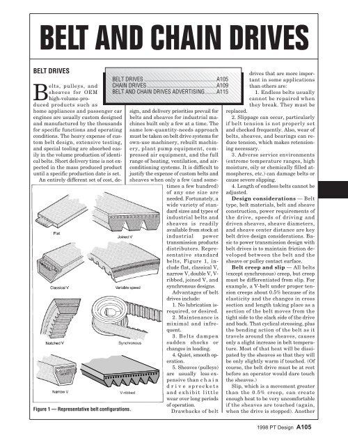
BELT AND CHAIN DRIVESBELT DRIVESBELT DRIVES ...................................................A105CHAIN DRIVES.................................................A109BELT AND CHAIN DRIVES ADVERTISING........A115sign, and delivery priorities prevail forbelts and sheaves for industrial machinesbuilt only a few at a time. Thesame low-quantity-needs approachmust be taken on belt drive systems forown-use machinery, rebuilt machinery,plant pump equipment, compressedair equipment, and the fullrange of heating, ventilation, and airconditioningsystems. It is difficult tojustify the expense of custom belts andsheaves when only a few (and sometimesa few hundred)of any one size areneeded. Fortunately, awide variety of standardsizes and types ofindustrial belts andsheaves is readilyavailable from stock atindustrial powertransmission productsdistributors. Representativestandardbelts, Figure 1, includeflat, classical V,narrow V, double V, V-ribbed, joined V, andsynchronous designs.Advantages of beltdrives include:1. No lubrication isrequired,or desired.2. Maintenance isminimal and infrequent.3. Belts dampensudden shocks orchanges in loading.4. Quiet, smooth operation.5. Sheaves (pulleys)are usually less expensivethan chaindrive sprocketsand exhibit littlewear over long periodsof operation.Drawbacks of beltV-ribbedFigure 1 — Representative belt configurations.Belts, pulleys, andsheaves for OEMhigh-volume-producedproducts such ashome appliances and passenger carengines are usually custom designedand manufactured by the thousandsfor specific functions and operatingconditions. The heavy expense of custombelt design, extensive testing,and special tooling are absorbed easilyin the volume production of identicalbelts. Short delivery time is not expectedin the mass produced productuntil a specific production date is set.An entirely different set of cost, <strong>dedrives</strong>that are more importantin some applicationsthan others are:1. Endless belts usuallycannot be repaired whenthey break. They must bereplaced.2. Slippage can occur, particularlyif belt tension is not properly setand checked frequently. Also, wear ofbelts, sheaves, and bearings can reducetension, which makes retensioningnecessary.3. Adverse service environments(extreme temperature ranges, highmoisture, oily or chemically filled atmospheres,etc.) can damage belts orcause severe slipping.4. Length of endless belts cannot beadjusted.Design considerations — Belttype, belt materials, belt and sheaveconstruction, power requirements ofthe drive, speeds of driving anddriven sheaves, sheave diameters,and sheave center distance are keybelt drive design considerations. Basicto power transmission design withbelt drives is to maintain friction developedbetween the belt and thesheave or pulley contact surface.Belt creep and slip — All belts(except synchronous) creep, but creepmust be differentiated from slip. Forexample, a V-belt under proper tensioncreeps about 0.5% because of itselasticity and the changes in crosssection and length taking place as asection of the belt moves from thetight side to the slack side of the driveand back. That cyclical stressing, plusthe bending action of the belt as ittravels around the sheaves, causesonly a slight increase in belt temperature.Most of that heat will be dissipatedby the sheaves so that they willbe only slightly warm if touched. (Ofcourse, the belt drive must be at restbefore an operator would dare touchthe sheaves.)Slip, which is a movement greaterthan the 0.5% creep, can createenough heat to be very uncomfortableif the sheaves are touched (again,when the drive is stopped). Another1998 PT Design A105
way to check for slip is to touch thebelt (when it is stopped). If the belt isuncomfortable to the touch (over 140F), it probably needs to be tightened.Belt tension — Checking operatingtemperatures of sheaves and belts (thetouch test) is but one of several waysexperienced machine operators andplant maintenance people check belttension without the need for complicatedmeasurements and calculations.Other equally simple and usefulbelt tensioning approaches involve visualand sound techniques. The bowor sag on the slack side of belt drivesincreases as a drive approaches fullload. Undulations and flutter on theslack side of belts can be very informativeto the experienced eye. Propertensioning can reduce or eliminatethese conditions.Tension adjustment based on beltsound can be a useful technique.Loads such as industrial fans requirepeak torque at starting. If belts squealas the motor comes on or at some subsequentpeak load, experienced beltpeople say the belts should be tighteneduntil the squeal disappears.Calculating V-belt tension —Figure 2 represents a belt drive arrangementwhich can be used to studyfactors affecting V-belt tensions andstresses. At standstill, the belt strandtensions T 1 and T 2 are equal. Whenload is applied to the driving pulley,tension T 1 increases and T 2 decreases.Figure 2 — Effective belt tension is thedifference between tight-strand andslack-strand tensions.T 1, tight side tension, divided by T 2slack side tension, is the tension ratioof a belt drive. The formula for tensionratio is as follows:Where:T 1 e kf φ=T2e 2.718 (the base of natural logarithm).k Wedging factor, from Figure 3,which is considered constant for aFigure 3 — Wedging action of V-beltincreases force of belt against sheavegroove and helps prevent slip.given drive.f Dynamic coefficient of frictionbetween belt and sheave. Wrap angle (arc of contact on thesmaller sheave in radians).K applies only to V-belt drives. Apractical tension ratio of 5 for V-beltsallows for such variations as lack ofrigidity of mountings, low initial tension,moisture, and load fluctuations.For rubber flat belt drives, a tensionratio of 2.5 is considered most efficient.The difference between tightstrandand slack-strand tensions iseffective tension, or T e T 1 T 2. Effectivetension is the actual force thatturns the driven sheave.Stress and power ratings — Theusable strength of a belt is the tensilestress the belt withstands for a specifiednumber of stress cycles, usuallythe equivalent of 3 years of continuousoperation, orabout 25,000 hr. Therelationships of effectivetension, T e (lb),belt stress ratings, S p(psi), and cross-sectionalarea, A (in. 2 ), ofthe belt are given inthe formula T e AS p.For belt drivetransmitted horsepower:Where:designed belts willnot run properly;they may slip, vibratetoo much, orturn over in thegrooves.All torque istransmittedthrough the belts,and torque doesnot change for agiven horsepower and speed. This basicconcept is best revealed in a multiple-beltdrive. For example, a multipleV-belt drive formerly requiring sevenbelts may need only five higher-ratedbelts with the same cross section. Forfive belts to deliver the same horsepoweras seven belts, each of the fivenew belts must carry more load. Increasedtension in the individual beltswill not overload the bearings, as someengineers may fear, because total tensionin the drive should be exactly thesame value. Each belt has a highertension, but there are fewer belts totransmit the tension to bearings.Belt typesFlat belts — Most of the generalprinciples of belt drive operation discussedearlier apply to flat belt drives.In calculating tension ratios for flatbelts, consult the manufacturer fortypical values of the friction coefficient,f. For a flat belt drive, k = 1.Several useful formulas for endlessbelts follow (refer to Figure 4). Forbelt length in an open belt drive:2( D−d)L0= 2C+ 1.57( D+d)+4CBelt length in a crossed belt drive:Lx = 2C + 1.57( D + d)+( )D+d4CTVhp = e33, 000V Belt velocity, fpm 0.262DND Pulley diameter, in.N Pulley speed, rpmGreat advancements have beenmade in various materials used in V-belts in recent years. Horsepower ratingsmay vary considerably from one Figure 4 — Basic dimensions forbelt to another. It’s important to providegreater tension for belts carrying lengths and arc of contact on smallercalculating open and crossed belthigher power. Otherwise the newly pulley or sheave.2weindex.infoA112 1997 Power Transmission Design
Where:C Center distance, in.d Small pulley diam., in.D Large pulley diam., in.Wrap angle or arc of contact on thesmaller pulley in degrees is:( D−d)φ = 180 −57.3CDrive system torque transmitted,lb-in., is:Tadaptable to practically any drive, althoughsometimes they may not beoptimal in terms of life-cycle cost orcompactness.Besides their wide availability, V-belts are often used in industrial andcommercial applications because oftheir relative low cost, ease of installationand maintenance, and wide rangeof sizes. The V shape obviously makesit easier to keep fast-moving belts insheave grooves than it is tokeep a flat belt on a pulley.Probably the biggest operationaladvantage of a V-belt isthat it is designed to wedge intothe sheave groove, Figure 3,which multiplies the frictionalforce it produces in tension and,in turn, reduces the tension requiredto produce equivalenttorque. Naturally, wedging actionrequires adequate clearancebetween the bottom of thebelt and the bottom of thesheave groove. The effect of thewedging factor, k, on the belttension ratio is shown in thesection that discusses V-belttension calculations.When V-belts first appeared in industrialapplications to replace wideflat belts, it was not unusual to use 10to 15 belts between a single pair ofshafts. Thus the term “multiple” beltsoriginated, which today is referred toas “classical multiple” or “heavy-dutyconventional” belts.Classical V-belts and matingsheaves have been standardized withletter designations from A through E,small to large cross sections. Thosestandard sizes are recognized worldwide.A and B sizes are frequentlyused individually but not the C, D,and E sizes because of cost and efficiencypenalties. Belts with cogged ornotched bases permit more severebends, which allows operation oversmaller diameter sheaves.Although classical V-belts can beused in some applications individually,they tend to be over designed fora number of light duty applications.Thus, a special category of belts hasevolved under the description singleV-belts; they are also denoted as fractionalhorsepower and light duty.Cross-sectional size designations runfrom 2L (the smallest) to 5L (thelargest). The 4L and 5L sections aredimensionally similar to A and B classicalbelts and can operate intervantageof the electrical conductivityof metal belts to ground conveyedparts that are sensitive to static electricity.Attachments, such as pins andbrackets, can be provided on metalbelts to carry, position, or locate partsbeing transported on the belt. Perforationsin the belts enable their use insprocket-driven applications forgreater positioning accuracy, Figure 5.Td = e2Figure 5 — Metal belt attachmentstransport or position parts. Perforatedbelts are used with sprockets to improveaccuracy.Endless round belts — An elastomericO-belt is a seamless, circularbelt that features a round cross sectionand an ability to stretch. AlthoughO-belts look like O-rings, theyare designed for power transmissionapplications. The elasticity of O-beltssimplifies design problems and reducescosts. However, they are limitedto subfractional horsepower applicationssuch as recorders,projectors, and business machines. O-belt materials include natural rubberand four polymers — neoprene, urethane,ethylene-propylene-terpolymer(EPT), and ethylene-propylenedienemonomer.Minimum pulley diameter is 6times the belt cross section. Pulleygrooves should be semicircular with aradius 0.45 of the cross-sectional diameterof the belt. Manufacturers cansupply charts showing the relationshipof O-belt horsepower and beltspeeds for various cross sections.V-belts — Available from virtuallyall power transmission componentsdistributors, standard V-belts areOne version of flat belting is anendless woven type that is made inseamless tubes. Materials are cottonand synthetic yarns, both spun filamentand continuous filament. Beltcarcasses can be impregnated andcoated with elastomers or syntheticresin. If an endless belt less than0.010 in. thick is needed, specify onemade of polyester film.Another material used for flat beltingis leather. The National IndustrialBelting Association (NIBA) providesinformation on belt speeds forstandard pulley diameters andwidths. NIBA divides pulleys intothree standard series: light duty (upto 40 hp), medium duty (40 to 75 hp),and heavy duty (75 to 150 hp).Flat belts with tension membersmade of nylons and polyesters are popularbecause they offer high strength-toweightratios and negligible permanentstretch. More favorable friction characteristicscan be achieved by laminatingnylon or polyester flat belting with afriction surface of chrome leather,polyurethane, rubber, PVC, or othermaterial. Laminated belts are usedwidely in industrial drives ranging fromfractional horsepower to more than6,000 hp at belt speeds to 20,000 fpm.Metal belts — Flat belts made ofmetal offer lightweight, compactdrives with little or no stretch. Endlessbelts are made by butt weldingthe ends with laser or electron-beammethods. Belts are generally availablein thicknesses ranging from0.002 to 0.030 in. and widths from0.030 to 24 in. Circumferential lengthranges from 6 in. to about 100 ft. Usuallymade of stainless steel, metalbelts have a high strength-to-weightratio, low creep, high accuracy, andresistance to corrosion and high temperature.Some applications take ad-weindex.info1997 Power Transmission Design A113
Table 1 — Standard dimensions of conventionalsynchronous beltsPitch, in. Length, in. Width, in.0.080 3.6 to 20.8 1/8, 3 /16, 1 /41/5 6 to 26 1/4, 3 /83/8 12.4 to 60 1/2, 3 /4, 11/2 24 to 180 3/4, 1, 1 1 /2, 2, 3`7/850.7 to 180 2, 3, 41 1 /4 70 to 180 2, 3, 4, 5duce a whippingaction in multiplebelt systems,which sometimescauses belts toturn over in thegrooves. The basicbelt element can beeither classical ornarrow. The joinedconfiguration avoids the need to ordermultiple belts as matched sets. Joined5V and 8V belts are available witharamid fiber reinforcement which offerextremely high power capacity —up to 125 hp per inch of width.V-ribbed belts combine some of thebest features of flat belts and V-belts.Tensioning requirements are not ashigh as flat belts but are about 20%more than V-belts. Five standard configurationsare available, with designationsH, J, K, L, and M. The M sectionis capable of transmitting up to1,000 hp. The power density permitscompact drive configurations, but thebelt is usually applied only in massproducedproducts.Belts for variable-speed drives requirespecial care in selection. Thosefor fixed-pitch drives, in which thespeed ratios are changed only atstandstill, are offered with sheavesfor 3L through 5L, A through D classical,and 5V and 8V narrow belts.For the adjustable (while running)variable speed drives, 4L, 5L, A, or Bbelts can be used if power requirementsare less than 2 hp and speedvariations are limited to 4.5:1. Specialwide belts have been developed forvariable-speed applications that accommodatespeed variations of up to9:1. There are 12 standard belt sec-changeably on A and B sheaves.Narrow V-belts are the latest stepin the evolution of a single-belt configuration.For a given belt width, narrowbelts offer higher power ratingsthan conventional V-belts. Narrowbelt size designations are standardizedas 3V, 5V, and 8V. They are alsoavailable in notched designs to maximizebending capability.Cogged, raw-edge belts have nocover, thus the cross-sectional areanormally occupied by the cover is usedfor more load-carrying cord. Cogs onthe inner surface of the belt increaseair flow to enhance cooler running.They also increase flexibility, enablingthe belt to operate with smallersheaves. Cogged belts are available inboth AX, BX, and CX Classical Vshapes plus 3VX and 5VX narrow Vconfigurations.Double sided or hexagonal beltscome in AA, BB, and CC narrow V-beltcross sections. These belts transferpower from either side in serpentinedrive configurations where a singlebelt operates with multiple pulleys.Joined V-belts solve special problemsfor conventional multiple V-beltdrives produced by pulsating loads,such as those generated by internalcombustion engines driving compressors.The intermittent forces can protionsdenoted by a four-digit numberfollowed by the letter V. Refer to theAdjustable-Speed Drives Product Departmentof this handbook for a discussionon these drives.Synchronous (timing) belts areused where input and output shaftsmust be synchronized. Trapezoidallyshaped teeth of the belt mate withmatching grooves in the pulleys toprovide the same positive, no-slip engagementof chain or gears. Standardsections are designated MXL, XL, L,H, XH, and XXH. Table 1 shows typicalsynchronous belt dimensions.Because stable belt length is essentialfor synchronous belts, they wereoriginally reinforced with steel. Today,glass fiber reinforcement is commonand aramid is used if maximumcapacity is required.Modifications of traditional trapezoidaltooth profiles to more circularforms offer more uniform load distribution,increased capacity, andsmoother, quieter action. Thesenewer synchronous belts incorporatea rounded curvilinear tooth design tohandle the higher torque capabilitiesnormally associated with chaindrives, Figure 6.Link-type V-belts consist of removablelinks that are joined by T-shapedrivets or interlocking tabs. Thesebelts offer application advantagessuch as installation without dismantlingdrive components, reduced beltinventory (no need for differentlengths), wide temperature range,and resistance to chemicals, abrasion,and shock loads. A matrix of polyesterfabric and polyurethane elastomerenables link-type belts to meet thehorsepower ratings of classical V-Figure 6 —Typicalsynchronousbeltand pulleywithtrapezoidalteeth, left,andcurvilineartooth,high-torquedrive, right.weindex.infoA114 1997 Power Transmission Design
elts. They are available in 3 /8through 7 /8-in. widths for speeds up to6,000 rpm.CHAIN DRIVESPower transmission chains can becategorized as roller chain, engineeringsteel chain, silent chain, detachablechain, and offset sidebar chain.Some of the advantages of chaindrives over belt drives are:• No slippage between chain andsprocket teeth.• Negligible stretch, allowingchains to carry heavy loads.• Long operating life expectancybecause flexure and friction contactoccur between hardened bearing surfacesseparated by an oil film.• Operates in hostile environmentssuch as high temperatures,high moisture or oily areas, dusty,dirty, and corrosive atmospheres, etc.,especially if high alloy metals andother special materials are used.• Long shelf life because metalchain ordinarily doesn’t deterioratewith age and is unaffected by sun,reasonable ranges of heat, moisture,and oil.• Certain types can be replacedwithout disturbing other componentsmounted on the same shafts assprockets.Drawbacks of chain drives thatmight affect drive system design are:• Noise is usually higher than withbelts or gears, but silent chain drivesare relatively quiet.• Chain drives can elongate due towearing of link and sprocket teethcontact surfaces.• Chain flexibility is limited to asingle plane whereas some belt drivesare not.• Usually limited to somewhatlower-speed applications compared tobelts or gears.• Sprockets usually should be replacedbecause of wear when wornchain is replaced. V-belt sheaves exhibitvery low wear.Each link of a chain drive transmitsload in tension to and from sprocketteeth. Because of the positive drivingcharacteristics of a chain drive, it requiresonly a few sprocket teeth for effectiveengagement that allows higherreduction ratios than are usually permittedwith belts. Load capacity ofchain drives can be increased withmultiple-strand chains.Types of chains and sprocketsThere is a wide variety of standardand nonstandard chain and sprocketdesigns. The American NationalStandards Institute (ANSI) has setstandards for chain that are prefixedANSI B29. The standards covertransmission and conveyor chain aswell as sprocket tooth dimensions,pitch diameters, and sprocket measuringprocedures. The best known ofall chain is roller chain, the first to bestandardized by ANSI.Roller chain — Flexure joints inroller chain contain pins that pivot insidethe roller bushings. The pins areusually press fitted into the pin linkplates, and roller bushings are pressfitted into roller link plates, Figure 7.The ANSI standard for single pitchroller chain is B29.1. A free-turningroller encircles each bushing to providerolling engagement and contactwith sprocket teeth.The distance between flexing jointsin roller chain is the pitch, which isthe basic designation for differentchain sizes. Larger pitch indicateslarger links with higher load ratings.Although a small pitch chain carriesless load, it offers smoother, quieteroperation than a chain of larger pitch.Standard sizes of roller chain varyfrom 1 /2 to 3-in. pitch. A nominal sizeis designated by multiplying pitch by80. Thus, a chain with a 1 /2-in. pitch isNo. 40.Also included in the roller chainstandard are two sizes that have norollers but are proportionedmuch like largerpitchroller chain. Theserollerless sizes have 1 /4and 3 /8-in. pitches andare designated No. 25and No. 35, respectively,with the 5 indicating therollerless design. Theoutside surface of eachchain link bushing contactsthe sprocket teethdirectly.The right-hand digitin roller chain designationis 0 for roller chainsof the usual proportions,1 for lightweight chain,and 5 for rollerlessbushed chain. A hyphenated numeral2 suffixed to the chain number denotesa double-strand, 3 a triplestrand,etc. Example numbers for sin-gle-strand roller chain are: No. 50chain indicates a 5 /8-in. pitch chain ofbasic proportions; and No. 35 indicatesa 3 /8-in. pitch rollerless busheddesign. In multiple strand rollerchain, 60-2 designates two strands ofa No. 60 chain in parallel having commonchain assembly pins, and 60-3designates a triple strand.Double-pitch roller chain —Also known as extended pitch chain,double-pitch roller chain dimensions,which are listed in the ANSI B29.3standard, are the same as standardroller chain with comparable load capacityexcept the pitch is doubled,Figure 8. Because a given length ofdouble-pitch chain contains only halfas many pitches, it is lighter and lessexpensive than standard roller chain.It is especially suitable for long centerdistance applications. Double-pitchroller chain offers essentially thesame strength characteristics asB29.1 chain because all dimensionsare the same except pitch. Doublepitchchain designation numbers add“20” preceding what would be a standardroller chain number. For example,2050 designates a 5 /8 2 or 1 1 /4-in. double-pitch roller chain.(Multiplying 5 /8 80 50 precededby 20 for the double pitch.)Sprockets for double-pitch rollerchain are either single-cut (one widetiptooth between each pair of chainrollers) or double-cut (two teeth betweeneach pair of chain rollers).Silent (inverted tooth) chain —Quieter running and more flexibleFigure 7 — Single pitch roller chain isavailable in pitch sizes above 3 /8 in.Single and multiple-strand versions areavailable.weindex.info1997 Power Transmission Design A115
Figure 8 — Double pitch roller chain.than conventional roller chain, silentchain, Figure 9, is available in 3 /16 to2-in. pitch sizes. Standards for inverted-toothchain are ANSI B29.2and B29.9.The several different types of silentchain construction prohibit mixingchains in a strand, but a chain of thecorrect size usually will operate onsprockets from a different manufacturer.Load capacity is increased bywidening silent chain rather than usingmultiple strands.For silent chain with a 3 /8-in. pitchor greater, an SC prefix in the chainsize designation indicates conformanceto ANSI B29.2. The first one ortwo digits following the SC indicatepitch in eighths of an inch followed bythe next two to three digits, which indicatechain width in 1 /4-in. increments.For example, SC1012 designatesANSI standard silent chainwith a 1 1 /4-in. pitch and a 3-in. width.For silent chain with a 3 /16-in. pitch,numbers following the 03 (whichidentifies the chain as 3 /16-in. pitch)indicate the total number of chainlinks wide. Width (or thickness) ofeach link is approximately 1 /32-in.Therefore, the number SC0314 designatesa 3 /16-in. pitch silent chain thatis approximately 7 /16-in. wide.Any of several techniques can beused to position silent chain axially onsprockets. In one technique, centerlink plates ride in circumferentialgrooves in the sprocket. In anothermethod, side link plates hold thechain in place on the sprocket axially.Detachable link chain — TheANSI standard for detachable linkchain is B29.6. The major advantageof chain with detachable links is thatthey can be separated at any jointwithout using special tools. Of course,the mountings for one or both sprocketsmust be loosened and the sprocketsmoved closer together to loosenthe chain. This procedure allows positioningadjacent links at such an angleto each other that they can betaken apart by sliding a pair of connectinglinks sideways.Detachable link chains are fabricatedwith one-piece elements; eitherpress-formed from flat rolled steel,Figure 10A, or cast in malleable ironFigure 10 — Pressed steel detachable linkchain, A, and malleable iron detachablelink chain, B.or other ferrous metals with comparableproperties, Figure 10B. Pressedsteeldetachable chain links (ANSIB29.6) typically range in size from 0.9to 2.3-in. pitch. The typical pitchrange for cast detachable chain links(formerly ANSI B29.7, now withdrawn)is 0.9 to 4 in.Detachable chain is low in cost andcan transmit up to 25 hp at speeds to350 fpm. It is not as smooth runningas precision chain and does not requirelubrication.Engineering steel chain —Where the transmission of high poweris the primary requirement, engineeringsteel drive chains offer many usefulsolutions. Engineering steelchains are perhaps the most widelyused, with applications mainly in industrialdrives and conveyors. Standardsfor heavy duty, offset sidebartype engineering steel roller chain,Fig. 11A, are given in ANSI B29.10.Specifications for heavy dutystraight-sidebar, roller-type conveyorFigure 9 — Inverted tooth (silent) chain drive. These sprockets are grooved for centerguide chain.Figure 11 — Heavy duty, offset sidebarengineering steel roller chain, A, andheavy duty, straight sidebar roller typeconveyor chain, B.A116 1997 Power Transmission Design
chain, Fig. 11B, are covered in theANSI B29.15 standard, steel bushedrollerless chain in B29.12, weldedsteel mill chain in B29.16, and dragchain in B29.18.Shaft center distance — In general,the preferred range of center distancefor roller chain drives that allowadjustable center distances is 30 to 50chain pitches, Figure 12. Roller chaindrives with fixed centers should belimited to about 30 pitches.Obviously, the minimum centerdistance must allow clearance betweenthe teeth of the two sprockets.Other than that requirement, the arcof chain engagement should not beless than 120 deg, Figure 13. For ratiosof 3:1 or less, there will be 120 degor more of wrap.Figure 12 — Preferred range of centerdistance for roller chain drives.A center distance equivalent to 80pitches is usually considered a practicalmaximum. Very long center distancescause excessive tension andmay cause the chain to jump teeth.Long chains may need to be supportedby guides or idlers. Idlers are discussedin the PT Accessories ProductDepartment of this handbook. Otherdrive system design approaches forextremely long center distances are touse two or more chain drives in series,or the lighter-weight double-pitchchain may be the answer where speedis slow and loading is moderate.Chain application principles —Regardless of the type or class ofchain, most of the following items areneeded to design a chain drive:1. Type of input power source (electricmotor, internal combustion engine,etc.).2. Type of driven load (uniformload, moderate shock, heavy shock).3. Power (hp) to be transferred.4. Full-load speed of fastest shaft.5. Desired speed of slow shaft.6. Shaft diameters.7. Center distance between shafts.(If distance is adjustable, what is therange of adjustment?)8. Limits onspace and positionof drive.9. Proposed lubricationmethod.10. Special conditionssuch asdrives with morethan two sprockets,use of idlers,abrasive or corrosiveenvironments,extreme temperatures, andwide variations in load and speed.These data, when used with publishedchain capacity ratings, allowthe designer to select the proper drivefor each application. ANSI B29 standardscontain capacityratings asdo chain manufacturers’catalogs.Standards coveringroller chainand inverted toothchain providehorsepower-capacitytabulations fora wide range ofsprocket sizes androtational speeds.Standards for detachablechaincover only allowableworkingloads. Standardsand some manufacturers’literaturecontain bothallowable workingloads and horsepower-capacitytabulations for off-Figure 13 — Arc ofroller chainengagement shouldnot be less than120 deg.set sidebar chain.Ratings for mostpower applicationchains are basedon life of 15,000 to20,000 hr assumingalignment, lubrication,andmaintenance requirementsare met. See Table 2 formaximum horsepower vs. sprocketspeed data. It is best to apply generousservice factors, as high as 1.7, especiallyif heavy shock loading isanticipated. See Table 3 for recommendedservice factor data.Sprockets are also covered by ANSIstandards. Various types of sprocketsare available including cast iron, powderedmetal, flame-cut steel plate,machined metal, and plastic materials.Special-purpose sprockets are offeredwith shear pins, overloadclutches, and other devices to protectagainst shock or overload.Speed ratios should not exceed 10:1for roller or silent chain and a limit of6:1 for other types. If needed, use double-reductiondrives to stay withinthose limits. For roller chain operat-Table 2 — Maximum hp capacity at various speedsfor 15-tooth sprocketsMaximum horsepower capacitySprocket Roller chainspeed, Single Four Double Offsetrpm strand strand pitch sidebar100 101 333 21.5 241200 188 620 21.1 290400 297 980 8.5 270600 140 462 6.6 140800 83.5 276 4.31,000 59.7 1971,200 41.4 1371,400 29.5 97.41,600 21.3 70.31,800 17.9 59.02,000 13.2 43.52,200 11.4 37.62,400 10.0 33.02,600 7.4 24.62,800 6.7 22.13,000 6.0 19.81997 Power Transmission Design A117
Table 3—Service factorsTable 4—Load classificationsTable 5 — Horsepower ratings, standard, single-strand No. 50 roller chain (5/8-in. pitch)Number ofteeth onRevolutions per minute—small sprocketsmallsprocket 100 200 300 500 700 900 1,000 1,200 1,400 1,600 1,800 2,100 2,400 2,700 3,09 0.67 1.26 1.81 2.87 3.89 4.88 5.36 6.32 6.02 4.92 4.13 3.27 2.68 2.25 1.10 0.76 1.41 2.03 3.22 4.36 5.46 6.01 7.08 7.05 5.77 4.83 3.84 3.14 2.63 2.11 0.84 1.56 2.25 3.57 4.83 6.06 6.66 7.85 8.13 6.65 5.58 4.42 3.62 3.04 2.12 0.92 1.72 2.47 3.92 5.31 6.65 7.31 8.62 9.26 7.58 6.35 5.04 4.13 3.46 2.13 1.00 1.87 2.70 4.27 5.78 7.25 7.97 9.40 10.4 8.55 7.16 5.69 4.65 3.90 3.14 1.09 2.03 2.92 4.63 6.27 7.86 8.64 10.2 11.7 9.55 8.01 6.35 5.20 4.36 3.15 1.17 2.19 3.15 4.99 6.75 8.47 9.31 11.0 12.6 10.6 8.88 7.05 5.77 4.83 4.16 1.26 2.34 3.38 5.35 7.24 9.08 9.98 11.8 13.5 11.7 9.78 7.76 6.35 5.32 4.18 1.43 2.66 3.83 6.07 8.22 10.3 11.3 13.4 15.3 13.9 11.7 9.26 7.58 6.35 5.20 1.60 2.98 4.30 6.80 9.21 11.5 12.7 15.0 17.2 16.3 13.7 10.8 8.88 7.44 6.22 1.77 3.31 4.76 7.54 10.2 12.8 14.1 16.6 19.1 18.8 15.8 12.5 10.2 8.59 7.24 1.95 3.63 5.23 8.29 11.2 14.1 15.5 18.2 20.9 21.4 18.0 14.3 11.7 9.78 8.26 2.12 3.96 5.70 9.03 12.2 15.3 16.9 19.9 22.8 24.2 20.3 16.1 13.2 11.0 9.28 2.30 4.29 6.18 9.79 13.2 16.6 18.3 21.5 24.7 27.0 22.6 18.0 14.7 12.3 1030 2.49 4.62 6.66 10.5 14.3 17.9 19.7 23.2 26.6 30.0 25.1 19.9 16.3 13.7 1132 2.66 4.96 7.14 11.3 15.3 19.2 21.1 24.9 28.6 32.2 27.7 22.0 18.0 15.1 12Type A Type B Type CA118 1997 Power Transmission Design
Figure 14 — Roller chainpitch selection chart.ing at low speed, thesmaller sprocket couldusually operate effectivelywith 12 to 17teeth. At high speeds,the smaller sprocketshould have at least 25teeth.Roller chain drivedesign exampleProblem: Select anelectric-motor-drivenroller chain drive totransmit 10 hp from acountershaft to themain shaft of a wiredrawing machine. Thecountershaft has a1 15 /16-in. diam. and operatesat 1,200 rpm. The main shaftalso has 1 15 /16-in. diam. and must operatebetween 378 and 382 rpm. Shaftcenters, once established,arefixed and by initialcalculations3,000 4,000 5,0001.92 1.25 0.892.25 1.46 1.042.59 1.68 1.202.95 1.92 1.373.33 2.16 1.553.72 2.42 1.734.13 2.68 1.924.55 2.95 2.115.42 3.52 2.526.35 4.13 2.957.33 4.76 3.418.35 5.42 09.42 6.12 010.5 6.84 011.7 7.58 012.9 8.35 0must be approximately22 1 /2 in.The load on themain shaft exhibits“peaks,”which places itin the heavyshock load category.All driveparts are pressurelubricatedfrom a centralsystem; therefore,the drivewill receiveType C lubrication.Step 1. Servicefactor —Classification for this drive is listed inTable 4 as heavy shock load. The servicefactor from Table 3 for heavyshock load and electric motor is 1.5.Step 2. Design horsepower —The design horsepower is 10 1.515 hp.Step 3. Tentative chain selection— On the pitch selection chart,Figure 14, locate 15 hp under the single-strandcolumn at the left, andthen follow the horizontal “horsepower”line across the chart to whereit intersects with the vertical 1,200-rpm line for the small sprocket. Thisintersection clearly lies in the diagonalarea for No. 50 roller chain.Step 4. Final selection of chainand small sprocket — On the horsepowerrating table, Table 5, for No. 50chain at 1,200 rpm, the computed designhorsepower of 15 hp is realizedwith a 20-tooth sprocket. Table 6shows that this sprocket will acceptthe specified shaft.Step 5. Selection of the largesprocket — Because the driver is tooperate at 1,200 rpm and the drivenat a minimum of 378 rpm, the speedratio 1,200 387 3.175 minimum.Therefore, the large sprocketshould have 20 3.175 teeth = 63.50teeth (use 63).This combination of 20 and 63 teethwill produce a main drive shaft speedof 381 rpm, which is within the limitationof 378 to 382 rpm.Step 6. Possible alternate —Sometimes space for a sprocket is limited,or higher capacity is needed froma given chain size. In this case, selecta multiple-strand chain drive. For example,a double-strand drive transmits1.7 times the power of a singlestrand drive of the same pitch.Step 7. Chain length — Because20 and 63-tooth sprockets are to beplaced in 22 1 /2-in. centers, the calculatedchain length is:2N+ n N−nL= C++( )22 24πC1997 Power Transmission Design A119
Table 6 — Maximum bore diameters of roller chain sprockets (with standard keyways)Chain pitch, in.Number of teeth3 ⁄81 ⁄25 ⁄83 ⁄4 1 11 ⁄2 2 21 ⁄2125 ⁄8 7/8 15 ⁄32 1 9 /32 1 25 /32 2 3 /4 3 5 /8 4 23 /3214 27 /32 1 5 /32 1 5 /16 1 3 /4 2 9 /32 3 5 /16 4 11 /16 5 23 /3216 31 /32 1 9 /32 1 11 /16 1 31 /32 2 23 /32 4 5 1 /2 718 1 7 /32 1 17 /32 1 7 /8 2 9 /32 3 1 /8 4 21 /32 6 1 /4 8 1 /820 1 9 /32 1 25 /32 2 1 /4 2 11 /16 3 1 /2 5 7 /16 7 9 3 /422 1 7 /16 1 15 /16 2 7 /16 2 15 /16 3 7 /8 5 7 /8 8 3 /8 10 7 /824 1 11 /16 2 1 /4 2 13 /16 3 1 /4 4 9 /16 6 13 /16 9 5 /8 13Where:L Chain length, pitchesC Shaft centers, pitchesN Number of teeth in largesprocketn Number of teeth in smallsprocketSubstituting values for C, N, and nyields L 114.8 in.Step 8. Correction of center distance— Because chain is to couple atan even number of pitches, use 114pitches and recompute the centers: pitch roller chain. In Table 5, Type Blubrication is indicated and the2 2N+ n ⎛ N+n⎞N n existing central lubricationL−+ ⎜ L − ⎟ system exceeds this requirement.■⎝ ⎠−8( − )2 224πC =4C = 35. 6 pitches or 22.25 in.Summary — Our final solution is20 and 63-tooth sprockets mounted on22.25-in. centers using No. 50, 5 ⁄8-in.The sample problem appearingabove is reprinted from Chains forPower Transmission and MaterialHandling, edited by L.L. Faulkner andS.B. Menkes, pages 142-145, by courtesyof Marcel Dekker, Inc., New York.A120 1997 Power Transmission Design