pushbutton pushbuttons pullrelief pushbuttons
LCU8020 - Philips Lighting
LCU8020 - Philips Lighting

You also want an ePaper? Increase the reach of your titles
YUMPU automatically turns print PDFs into web optimized ePapers that Google loves.
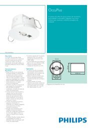
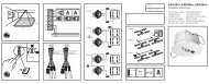
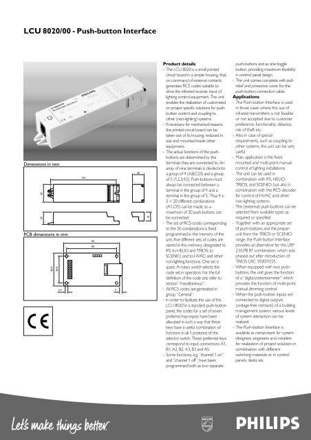
LCU 8020/00 - Push-button InterfaceDimensions in mm2840PCB dimensions in mm36.629.914263563.5 42519Product details- The LCU 8020 is a small printedcircuit board in a simple housing, that,on command of external contacts,generates RC5 codes suitable todrive the infrared receiver input oflighting control equipment. The unitenables the realization of customizedor project specific solutions for <strong>pushbutton</strong>control and coupling toother (non-lighting) systems.- If necessary for mechanical reasons,the printed circuit board can betaken out of its housing, reduced insize and mounted inside otherequipment.- The actual functions of the <strong>pushbutton</strong>sare determined by theterminals they are connected to. Anarray of nine terminals is divided intoa group of 4 (A,B,C,D) and a groupof 5 (1,2,3,4,5). Push-buttons mustalways be connected between aterminal in the group of 4 and aterminal in the group of 5. Thus 4 x5 = 20 different combinations(A1..D5) can be made, so amaximum of 20 push-buttons canbe connected.- The set of RC5 codes correspondingto the 20 combinations is fixedprogrammed in the memory of theunit. Five different sets of codes arestored in this memory, designated toIFS, to HELIO and TRIOS, toSCENIO, and to HVAC and othernon-lighting functions. One set isspare. A rotary switch selects thecode set in operation. For the fulldefinition of the code sets refer tosection ”miscellaneous”.- All RC5 codes are generated ingroup ”General”.- In order to facilitate the use of theLCU 8020 in a standard push-buttonpanel, the codes for a set of sevenpreferred key-inputs have beenallocated in such a way that thesekeys have a useful combination offunctions in all 5 positions of theselector switch. These preferred keyscorrespond to input connections A1,B1, A2, B2, A3, B3 and A5.- Some functions, e.g. ”channel 1 on”and ”channel 1 off”, have beenprogrammed both as two separatepush-buttons and as one togglebutton, providing maximum flexibilityin control panel design.- The unit comes complete with <strong>pullrelief</strong>and protective cover for thepush-button connection cable.Applications- The Push-button Interface is usedin those cases where the use ofinfrared transmitters is not feasibleor not accepted due to customerpreference, functionality, distance,risk of theft etc.- Also in case of specialrequirements, such as coupling toother systems, the unit can be veryuseful.- Main application is the fixedmounted and multi-point manualcontrol of lighting installations.- The unit can be used incombination with IFS, HELIO,TRIOS, and SCENIO, but also incombination with the RC5 decoderfor control of HVAC and othernon-lighting systems.- The (external) push-buttons can beselected from available types asrequired or specified.- Together with an appropriate setof push-buttons and the properunit from the TRIOS or SCENIOrange, the Push-button Interfaceprovides an alternative for the LRP23/LPB 81 combination, which wasphased out after introduction ofTRIOS LRC 1030/1035.- When equipped with two <strong>pushbutton</strong>s,the unit gives the functionof a ”digital potentiometer” whichprovides the function of multi-pointmanual dimming control.- When the push-button inputs areconnected to digital outputs(voltage-free contacts) of a buildingmanagement system, various levelsof system interaction can berealized.- The Push-button Interface isavailable as component for systemdesigners, engineers and installersfor realization of project solutions incombination with differentswitching materials or in controlpanels, desks etc.
LCU 8020/00 - Push-button InterfaceRelated equipmentLighting Management Systems:IFS: local units BLU 10/11, BLU 10/12, BLU 10/13DLU 10/01, DLU 10/31, LRC 4070HELIO: light controller LRC 5040Stand-alone control:TRIOS: light controllers LRC 1010, LRC 1020, LRC 1030LRC 1015, LRC 1025, LRC 1035SCENIO: light controller LRC 1555extension module LRC 1505General Purpose Components:cables: sensor cables LCC 8011, LCC 8012, LCC 8013, LCC 8014,branching connector LCC 8024sensors: infrared receivers IRR 8124, MCS 9010, MCS 9020multi-sensor LRI 8133Technical dataInputmore push-buttons on one interfacemore interfaces on one push-buttonOutputcodingoutput low voltageoutput high voltagemax. output current sourcedmax. output current sinkedshort circuit currentIndicatorPower supplyElectrical connectionsPush-button inputsconnectors: push-button contacts(normally open)V open : 5 VdcI closed : 250 µAt closed min. : 50 ms: allowed: not allowed.: bi-phase RC5 codes: < 1.0 V: > 3.5 V: 10 mA: 0.1 mA: 50 mA (pin 5 of modularsocket connected to ground).outputs can be ”wired-or” upto a total of 6 interfacesone output can drive upto 5 controller inputs.: red LED, indicating thegeneration of RC5 signals: 12 Vdc ±10%, 5 mAderived from connectedcontroller.short-circuit of supply < 1 A.wire size : AWG 26 - 16stranded : 1.0 mm 2solid : 1.0 mm 2RC5 output: 9 pole screw connector(can be replaced by header pins): modular socket (”Telejack”)standard pinning:1. 12 Vdc supply voltage2. ground3. +5 Vdc supply voltage (n.a.)4. light sensor output signal (n.a.)5. infrared receiver output signal(RC5)6. movement detector outputsignal (n.a.)Housingcolour : white (90064)material: Lexan 161 Rflame rating: UL 94 V2glow wire test : 750 °C (IEC 695-2-1)ball pressure : 125 °C (IEC 335-1)Operating conditionsambient temperature : +5 - +50 °Crelative humidity: 20 - 85 %, no condensationStorage conditionsambient temperature : -25 - +85 °Crelative humidity : 10 - 95 %EMCimmunity : in accordance with EN 50082-1radiated interference : in accordance with EN 50081-1safety: Class IIIReliabilitycall rate: 1% per year (estimated)life time: 10 years (estimated)Dimensions (l x w x h)with housing : 159 x 40 x 28 mmwithout housing (small size) : 67 x 36,6 x 20 mmWeightwith housing: 77 gwithout housing (small size) : 15 gMountingwith housing: two open-ended slotsfor 4 mm diameter screwswithout housing (small size) : 3.5 mm holes in the fourcorners of the PCB
LCU 8020/00 - Push-button InterfaceTable 5: CODE set 3 - SCENIOA B C D1 Preset 1 30 03 Preset 2 30 04 Preset 7 30 18 Preset 8 30 192 Preset 3 30 00 Preset 4 30 07 Preset 9 30 20 Preset 10 30 213 Down 30 42 Up 30 41 Preset 11 30 22 Preset 12 30 23Stop 30 46 Stop 30 46(toggle)(toggle)4 Preset 5 30 16 Preset 6 30 17 Preset 13 30 25 Preset 14 30 265 All Off 30 63 Up 30 41 Down 30 42 Stop 30 46Remarks: Toggle key A3 (”Down - stop”) is automatically reset to the ”Down” position each time any other key is pressed.Toggle key B3 (”Up - stop”) is automatically reset to the ”Up” position each time any other key is pressed.This automatic reset ensures logical operation after the up or down action was stopped by one of the other keys.Table 6: CODE SET 4 - HVAC, WINDOW BLINDS, OFFICE EQUIPMENTA B C D1 Preset 1 30 51 Preset 2 30 52 HVAC 30 125 HVAC 30 125Comfort + NUM Comfort + NUMTemp. downTemp. up2 1 Off/Down 30 58 1 On/Up 30 57 Preset 1 30 51 Preset 2 30 523 Blinds Down 30 121 Blinds Up 30 120 1 Off/Down 30 58 1 On/Up 30 57Stop 30 122 Stop 30 122(toggle)(toggle)4 Blinds Down 30 121 Blinds Up 30 120 2 Off/Down 30 62 2 On/Up 30 615 All Off, 30 63 Blinds Stop 30 122 All Off 30 63 HVAC 30 126Absent 30 127 Absent 30 127 StandbyRemarks: Toggle key A3 (”Blinds Down - Stop”) is automatically reset to the ”Blinds Down” positioneach time key B3 (”Blinds Up - Stop”) is pressed.Toggle key B3 (”Blinds Up - Stop”) is automatically reset to the ”Blinds Up” positioneach time key A3 (”Blinds Down - Stop”) is pressed.This automatic reset eliminates synchtronisation problems due to commands not generated with this push-button interface,e.g. blinds stopped by the end stop switch.Keys C5 (”All Off, Absent”) and D5 (”HVAC Stand-by”) will switch off the setpoint indication LED’s or 7 segment display.
LCU 8020/00 - Push-button InterfaceFunction of HVAC outputsTable 3: CODE SET 1 – IFSA B C D1 1 Off/ Down 30 58 1 On/ Up 30 572 2 Off/ Down 30 62 2 On/ Up 30 613 3 Off/ Down 30 60 3 On/ Up 30 5945 All Off 30 63 1 On 30 37 2 On 30 61 3 On 30 591 Off 30 58 2 Off 30 62 3 Off 30 60(toggle) (toggle) (toggle)Remarks: IFS commands 1,2 and 3 can also be used for HELIO and Trios channel 1, channel 2 and channel 3.Toggle keys B5, C5 and D5 are automatically reset to the "On" position, when key "All Off" (A5) is pressed.This automatic reset eliminates synchronization problems due to commands initiated by the "All Off" key.Table 4: CODE SET 2 – HELIO/ TRIOSA B C D1 Preset 1 30 51 Preset 2 30 52 Ch 3 Off/Down 30 60 Ch 3 On/Up 30 592 Preset 3 30 48 Preset 4 30 55 Ch 4 Off/Down 30 50 Ch 4 On/Up 30 493 Ch 1 Off/Down 30 58 Ch 1 On/Up 30 57 Ch 5 Off/Down 30 54 Ch 5 on/up 30 534 Ch 2 Off/Down 30 62 Ch 2 On/Up 30 61 Green 30 56 Store 30 56button 30 585 All Off 30 63 Preset 1 30 51 All Off 30 63 Preset 1 30 51All Off 30 63 Preset 2 30 52(toggle)(toggle)Remarks: HELIO and Trios command Channel 1, Channel 2 and Channel 3 can also be used for IFS 1, 2, and 3.Toggle keys B5 and D5 are automatically reset to the ”Preset 1” position when key ”All Off” (A5, C5) is pressed.This automatic reset eliminates synchronisation problems due to commands initiated by the ”All Off” key.
LCU 8020/00 - Push-button Interface3222 636 3008104/2001Printed in the NetherlandsData Subject to changewww.controls4lighting.comTable 7: CODE SET 5 – CENTRAL CONTROL WITH PUSH-BUTTON INTERFACE LCU 8020This is a special mode for use in projects only. In this mode (5) the push-button interface LCU 8020 can be used for central control functions. For moredetailed descriptions on the functionality and the installation is referred to the TRIOS- system handbook.In the following table the general commands are displayed.Required Terminals to be connected Transmittedfunction to common return RC5-codeA B C DPreset 1 • 30 51Preset 2 • 30 52Ch. 1 on • • 30 57Preset 3 • 30 48Ch. 2 on • • 30 61Blinds down • • 30 121Preset 4 • • • 30 55All off • 30 63Blinds up • • 30 120Ch.2 off • • 30 62Ch.3 on • • • 30 59Ch.1 off • • 30 58Ch.3 off • • • 30 60Blocking • • • 29 101Deblocking • • • • 29 102Remark:When terminals A plus B plus C are connected to the common return, a "BLOCKING" command will be sent to the TRIOS units. From that momenton, TRIOS will no longer react to any local or central command or any local sensor signal. The situation can only be released by sending the"DEBLOCKING" command (A plus B plus C plus D connected to the common return).As an exception to the rule, parallel connection of the push-button interfaces is allowed, but only when using code set 5.Related documentationInstallation instructions 3222 609 26451Engineering and Service manual IFS (English) 3222 635 09491HELIO System Handbook LCH 5900/00 (English) 9130 010 00003HELIO Energy Saving Handbook LCH 5915/00 (English) 9137 010 00203SCENIO System Handbook LCH 1599/00 (English) 9137 010 00403Technical Application Manual Trios (English) 3222 010 00403TRIOS System Handbook LCH 1099/00 (English) 9137 010 00503PhilipsLighting