Solutions to Additional Conceptual Practice Problems for PHYS 1112 Final Exam
PHYS 1112 – Exam 4 w Solutions (2010) – Intro to Physics 2
PHYS 1112 – Exam 4 w Solutions (2010) – Intro to Physics 2

You also want an ePaper? Increase the reach of your titles
YUMPU automatically turns print PDFs into web optimized ePapers that Google loves.
Physics <strong>1112</strong>Spring 2009University of GeorgiaInstruc<strong>to</strong>r: HBSchüttler<strong>Solutions</strong> <strong>to</strong> <strong>Additional</strong> <strong>Conceptual</strong> <strong>Practice</strong> <strong>Problems</strong><strong>for</strong><strong>PHYS</strong> <strong>1112</strong> <strong>Final</strong> <strong>Exam</strong>Mon. May 4, 2009, 7:00pm-10:00pmCP 4.01:Answer: (A)1
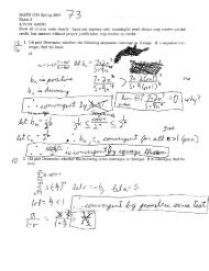
Physics <strong>1112</strong>Spring 2009University of GeorgiaInstruc<strong>to</strong>r: HBSchüttlerDetailed Problem Statement:A bar magnet is moved either <strong>to</strong>wards or away from a circular conducting ring with eitherits north-pole (N) or its south-pole (S) pointing <strong>to</strong>wards the ring, and the respective polebeing located either above the plane of the ring (in ”Top” position ”T”) or below the planeof the ring (in ”Bot<strong>to</strong>m” position ”B”), as shown in the Fig. As also shown in Fig., theplane of the ring defines the x-y-plane, and the magnet’s N-S-axis is oriented parallel <strong>to</strong> thez-axis while the magnet is being moved.Which of the five motion processes of the bar magnet, (A)-(E) described above, will inducea clockwise (cw) current I in the ring?Solution:Above/below the poles of the bar magnet, ⃗ B points approximately along the z-axis, ou<strong>to</strong>f the N- and in<strong>to</strong> the S-pole, with the field strength B ≡ | ⃗ B| decreasing with increasingdistance from either pole.Hence, the magnetic field ⃗ B inside the ring points in +z-direction when the N-pole is belowthe ring pointing up (in Bot<strong>to</strong>m position ”B”) or when the S-pole is above the ring pointingdown (in Top position ”T”). Likewise, ⃗ B inside the ring points in −z-direction when theS-pole is below the ring pointing up (in Bot<strong>to</strong>m position ”B”) or when the N-pole is abovethe ring pointing down (in Top position ”T”). Also, the field strength B inside the ringincreases if either pole is moving <strong>to</strong>wards the ring; and the field strength B inside the ringdecreases if either pole is moving away from the ring.By Lenz’s rule, the induced current I in the ring produces a secondary field, ⃗ BI , whichopposes the change ∆ ⃗ B of the time-dependent inducing field ⃗ B(t). Also, the direction of I isrelated <strong>to</strong> the ⃗ B I -direction by a right-hand (RH) rule: if RH thumb is in direction of ⃗ B I , theRH 4 fingers point in the flow direction of I. So, <strong>to</strong> produce a ⃗ B I pointing in −z-directionrequires a clockwise I, as defined in Fig.; <strong>to</strong> produce a ⃗ B I pointing in +z-direction requiresa counter-clockwise I.Hence, ∆ ⃗ B points in +z-direction, and by Lenz’s rule, ⃗ B I points in −z-direction, and I flowsclockwise ifCase (1): ⃗ B points in +z-direction and its strength B increases in magnitude; orCase (2): ⃗ B points in −z-direction and its strength B decreases in magnitude.Likewise, ∆ ⃗ B points in −z-direction, and by Lenz’s rule, ⃗ B I points in +z-direction, and Iflows counter-clockwise ifCase (3): ⃗ B points in +z-direction and its strength B decreases in magnitude; orCase (4): ⃗ B points in −z-direction and its strength B increases in magnitude.Thus, in the answer key above, process (A) corresponds <strong>to</strong> Case (1), process (B) corresponds<strong>to</strong> Case (3), process (C) corresponds <strong>to</strong> Case (4), process (D) corresponds <strong>to</strong> Case (4), andprocess (E) corresponds <strong>to</strong> Case (3). So, only process (A) induces a clockwise current, while(B), (C), (D) and (E) all induce a counter-clockwise current in the ring.2
Physics <strong>1112</strong>Spring 2009University of GeorgiaInstruc<strong>to</strong>r: HBSchüttlerCP 4.02:Answer: (A)The induced EMF amplitude is E o = ABω where the loop’s angular speed is ω = 2πf,expressed in terms of the rotation frequency f. Hence, at fixed field strength B, E o ∝ A × f.So increasing A = 10cm 2 → A ′ = 30cm 2 = 3 × A and increasing f = 500RPM → f ′ =1500RPM = 3 × f will increase E o = 20mV → E o ′ = 3 × 3 × E o = 180mV3
Physics <strong>1112</strong>Spring 2009University of GeorgiaInstruc<strong>to</strong>r: HBSchüttlerCP 4.03:Answer: (D)By Kirchhoff’s loop rule E B + E = 0 where E = −L∆I/∆t is the self-induced EMF in theinductance L. Hence, ∆I/∆t = E B /L = 50V/10H = 5A/s.4
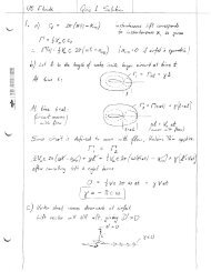
Physics <strong>1112</strong>Spring 2009University of GeorgiaInstruc<strong>to</strong>r: HBSchüttlerCP 4.04:mrSt1olE---j ,Q== Lf,LJI(Lasf?Y lJetJ.m'G ' ) (Las er 1> ct 'nil)Side View+a.kes Q 'lv\l~1 "'1a. se" b II , 0vad IU5 "R a,i5ce \re1'-1 ;vecled"5 &{C\ === 4-1(~ 8.0fi ({l-t >SI _ -~-----4___Pr-e» l.tv-{ cJtElq' '" >l (j r v I yIIAnswer: (E)To levitate a massive object of mass m, the downward weight <strong>for</strong>ce mg must be matchedby the upward radiation pressure <strong>for</strong>ce ΠA, i.e., mg = ΠA. Here A is the cross-sectionalbeam area <strong>to</strong> which the object is exposed (with A-surface perpendicular <strong>to</strong> beam direction);and Π = αI/c is the radiation pressure, with α = 1 <strong>for</strong> a 100% absorbing object and withα = 2 <strong>for</strong> a 100% reflecting object. Hence, solving <strong>for</strong> the time-averaged beam intensity:I = cmg/(αA) which impliesI ∝ m/(αA).So changing the massm S = 40pg → m D = 120pg = 3 × m S ;5
Physics <strong>1112</strong>Spring 2009University of GeorgiaInstruc<strong>to</strong>r: HBSchüttlerand changing the absorption-reflection fac<strong>to</strong>rα S = 1 → α D = 2 = 2 × α S ;and changing the exposure cross-section area from a circle of radius R <strong>to</strong> a square of 4Rsidelength, i.e.,A S = πR 2 → A D = (4R) 2 = (16/π) × A S ,will change the required intensity <strong>for</strong> levitationI S → I D = 3 × (2) −1 × (16/π) −1 × I S = (3π/32)I Ssince the levitation intensity I is proportional <strong>to</strong> m, but inversely proportional <strong>to</strong> α and A.6
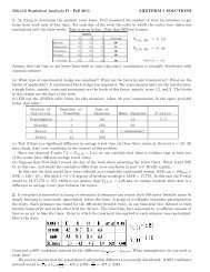
Physics <strong>1112</strong>Spring 2009University of GeorgiaInstruc<strong>to</strong>r: HBSchüttlerCP 4.05+4.06:OllfTu.O 0..,.1. gI, _---..Side. 'VJ'ofl'e'1/-eol---r----r-:-~-r-:--......;--=---~-~"O""'lj ~t {V1.f e~s( te'~I - 02.1------_.........:.-I~ -:::::: 0--Clv-e ~'PIrnrr.-~~ _~1iD~Q~ FytJ £- Viri f1 +-5 :CoS( OiJ)=(f3')/J..CoS (bOO) = 2CP 4.05 (=Q1), Answer: (B)For unpolarized light of time-averaged (TA) intensity I 0 passing through polarization filter(PF) 1, the TA intensity after the filter is I 1 = I 0 〈cos 2 θ 1 〉 θ . Here, 〈...〉 θ means averaging overall possible values of the random angle between an incident waves packet’s electric field E ⃗ 0and transmission axis T 1 , denoted by θ 1 ≡ ̸ ( E ⃗ 0 , T 1 ). For uni<strong>for</strong>mly random angle θ 1 (i.e.,any value of θ 1 between 0 o and 180 o is equally likely <strong>to</strong> be found among incident EM wavepackets), 〈cos 2 θ 1 〉 θ = 1/2 and hence I 1 = (1/2)I 0 .The wave packets passing through PF1 (i.e. between PF1 and PF2) are then polarized withelectric field vec<strong>to</strong>r E ⃗ 1 ‖ T 1 . But then the angle between E ⃗ 1 (incident upon PF2) and T 2 isθ 2 ≡ ̸ ( E ⃗ 1 , T 2 ) = 90 o , since T 2 ⊥ T 1 . Hence, by Malus’ Law, the TA intensity transmitted7
Physics <strong>1112</strong>Spring 2009University of GeorgiaInstruc<strong>to</strong>r: HBSchüttlerthrough PF2 is I 2 = I 1 cos 2 θ 2 = I 1 cos 2 (90 o ) = 0.CP 4.06 (=Q2), Answer: (E)As in CP 4.05, the intensity I 1 after PF1 is still I 1 = (1/2)I 0 with E ⃗ 1 ‖ T 1 . However, theangle between E ⃗ 1 and T 2 is now θ 2 ≡ ̸ ( E ⃗ 1 , T 2 ) = 90 o − 30 o = 60 o , since T 2 is 30 o from thehorizontal, but E ⃗ 1 ‖ T 1 , i.e., E ⃗ 1 is vertical. So, I 2 = I 1 cos 2 θ 2 = I 1 cos 2 (60 o ) = I 1 × (1/2) 2 =(1/2)I 0 × (1/2) 2 = (1/8)I 0 ; and thus I 2 /I 0 = 1/8.Important <strong>to</strong> note here: It does not matter here if you add or subtract 180 o from the ⃗ E-T angle θ, or change the sign of θ, since cos 2 (θ) = cos 2 (−θ) = cos 2 (θ±180 o ) = cos 2 (180 o ±θ).8
LNM8OBPQ0ROSUTM8ONVXWY[Z]\§V^^_K``Sba_Sca_>d[egfLhT" 4s+<strong>to</strong>hm8
Physics <strong>1112</strong>Spring 2009University of GeorgiaInstruc<strong>to</strong>r: HBSchüttlerof Φ m , with final values of flux Φ ′ m = B ′ A cos Θ ′ , magnetic field strength B ′ and angleΘ ′ ≡ ̸ ( A ⃗′ , B ⃗ ′ ), after changing the field/circuit configuration, as follows:(A) Φ ′ m = −BA < +BA = Φ m with Θ ′ = 180 o and B ′ = B;(B): Φ ′ m = 0 < BA = Φ m with Θ ′ = 90 o and B ′ = B;(C): Φ ′ m = B ′ A < BA = Φ m with Θ ′ = 0 o and B ′ < B;(D): Φ ′ m = BA = Φ m with Θ ′ = 0 o = Θ and B ′ = B;(E): Φ ′ m = B ′ A > BA = Φ m with Θ ′ = 0 o and B ′ > B;(F): Φ ′ m = 0 < BA = Φ m with Θ ′ = 90 o and B ′ = B.There<strong>for</strong>e, the time-dependent change of flux ∆Φ m ≡ Φ ′ m − Φ m and the resulting inducedEMF E = −∆Φ m /∆t (with ∆t > 0 here) have the following signs:∆Φ m < 0 and hence E > 0 <strong>for</strong> processes (A), (B), (C) and (F). By the sign convention <strong>for</strong>Faraday’s law, a positive EMF E > 0 drives the current I in the loop in right-hand (RH)direction around A ⃗ (i.e., point RH thumb in A-direction; ⃗ then 4 RH fingers will point inI-direction). Since A ⃗ was chosen <strong>to</strong> point in<strong>to</strong> the paper, ”RH direction around A” ⃗ means:clockwise. So, current I flows clockwise around the loop and there<strong>for</strong>e deposits positivecharge on the upper capaci<strong>to</strong>r plate (and an equal amount of negative charge on the lowercapaci<strong>to</strong>r plate) in processes (A), (B), (C) and (F).∆Φ m > 0 and hence E < 0 <strong>for</strong> process (E). By the sign convention <strong>for</strong> Faraday’s law, anegative EMF E < 0 drives the current I in the loop against RH direction around ⃗ AHence, current I flows counter-clockwise around the loop and there<strong>for</strong>e deposits negativecharge on the upper capaci<strong>to</strong>r plate (and an equal amount of positive charge on the lowercapaci<strong>to</strong>r plate) in process (E).∆Φ m = 0 and hence E = 0 <strong>for</strong> process (D). Hence, there is no induced EMF and no inducedcurrent I in the loop and there<strong>for</strong>e zero charge being deposited on the either capaci<strong>to</strong>r plate.For an alternative way of solving this, using Lenz’s rule, see posted solution of HomeworkProblem P08.01 <strong>for</strong> details.10