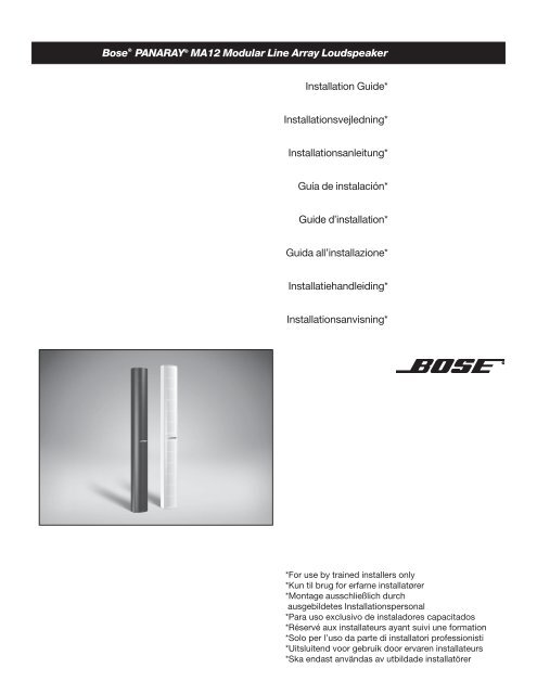
Panaray MA12 Modular Line Array Loudspeaker - Installation ... - Bose
Panaray MA12 Modular Line Array Loudspeaker - Installation ... - Bose
Panaray MA12 Modular Line Array Loudspeaker - Installation ... - Bose
- No tags were found...
You also want an ePaper? Increase the reach of your titles
YUMPU automatically turns print PDFs into web optimized ePapers that Google loves.
DECLARATION OF CONFORMITYWe, the offerer:<strong>Bose</strong> Corporation, The Mountain, Framingham, MA 01701-9168 USAacknowledge our sole responsibility, that the product:Kind of equipment:Type designation:<strong>Loudspeaker</strong>PANARAY ® <strong>MA12</strong> <strong>Modular</strong> <strong>Line</strong> <strong>Array</strong><strong>Loudspeaker</strong>In accordance with EMC Directive 89/336/EEC and Article 10(1) of the Directive,is in compliance with the following norm(s) or document(s):Technical regulations: EN50081-1, EN50082-1Accredited by:<strong>Bose</strong> Corporation, The Mountain, Framingham, MA 01701-9168 USAJanuary 15, 2001<strong>Bose</strong> Products B.V.Nijverheidstraat 8, 1135 GE EdamThe NetherlandsNic MerksVice President, EuropeManufacturer’s authorized EU representative2
<strong>Installation</strong> of <strong>MA12</strong> <strong>Modular</strong> <strong>Line</strong> <strong>Array</strong> <strong>Loudspeaker</strong>s.......continues on p11For Permanent <strong>Installation</strong>WARNING: Permanent installations involve the attachment of the loudspeakers to brackets or other mounting surfacesfor long-term or seasonal use. Such mountings, frequently in overhead locations, involve risk of personal injury if either themounting system or the loudspeaker attachment fails.<strong>Bose</strong> ® offers permanent mounting brackets for the safe use of these loudspeakers in suchinstallations. However, we realize some installations may call for use of other, customdesignedmounting solutions or non-<strong>Bose</strong> mounting products. While <strong>Bose</strong> Corporationcannot be held responsible for the proper design and use of non-<strong>Bose</strong> mounting systems,we offer the following guidelines for the permanent installation of any PANARAY ® <strong>MA12</strong>modular line array loudspeaker:• Obtain your mounting system from a reputable manufacturer, and make sure the systemis specifically designed for the loudspeaker of choice and your intended use.• Before using a custom-designed and fabricated mounting system, have a licensedprofessional engineer review the design and fabrication for structural integrity and safetyin the intended application.• Notice that all threaded attachment points on the rear of each loudspeaker cabinet havea metric M6 x 1 x 15 mm thread with 10 usable threads.• Use a safety cable, separately attached to the cabinet at a point not in common withthe load bearing attachment points of the bracket to the loudspeaker.• If you are unfamiliar with the proper design, use, and purpose of a safety cable, consult alicensed professional engineer, a rigging professional, or a theatrical lighting tradesprofessional.EnglishCAUTION: Use only graded hardware. Fasteners should be metric Grade 8.8 minimum and should be tightenedusing torque not to exceed 50 inch-pounds (5.6 Newton-meters). Overtightening the fastener could result in irreparabledamage to the cabinet and an unsafe assembly.Do not re-tighten these fasteners unless they are visibly loose. Characteristics of the cabinet may cause some relaxation oftightening torque over time, which is normal. Lockwashers or a thread locking compound intended for hand disassembly(such as Loctite ® 242) should be used for a vibration resistant assembly.CAUTION: The fastener should be long enough to engage no fewer than 8 and no more than 12 threads of theattachment point. A fastener should protrude by 8 to 10 mm, with 10 mm preferred ( 5 /16 to 3 /8 inch, with 3 /8 inch preferred)beyond the assembled mounting parts to provide sufficient threaded attachment to the loudspeaker. Using a fastener that istoo long may result in irreparable damage to the cabinet and, when overtightened, can create a potentially unsafe assembly.Using a fastener that is too short provides inadequate holding power and may strip the mounting threads, resulting in anunsafe assembly. Confirm that at least 8 full threads are engaged in your assembly.CAUTION: Do not attempt to alter the threaded attachment points. While SAE 1 / 4 - 20 UNC fasteners are verysimilar in appearance to the metric M6, they are not interchangeable. Do not attempt to re-thread the attachment points toaccommodate any other thread size or type. Doing this will render the installation unsafe and will permanently damage theloudspeaker. You may substitute 1 /4-inch washers and lockwashers for the 6 mm ones.3
Opstilling af <strong>MA12</strong> højttalere.................fortsættes på side 11Permanent installationDanskADVARSEL: Ved permanent installation fastgøres højttalerne på beslag eller andre ophæng til langtids- ellerperiodisk brug. Denne type montering, der ofte er placeret over hovedhøjde, indebærer en risiko for personskade, hvismonteringssystemet eller metoden til fastgørelse af højttalerne svigter.<strong>Bose</strong> tilbyder beslag til permanent og sikker montering af højttalere i denne typeinstallationer. Visse installationer kræver dog specialudformede monteringsløsninger ellermonteringsløsninger, som <strong>Bose</strong> ikke kan levere. <strong>Bose</strong> Corporation kan ikke holdes ansvarligfor den korrekte udformning af og brugen af monteringssystemer, der ikke er produceret af<strong>Bose</strong>, men angiver følgende retningslinjer for permanent installation af PANARAY ® <strong>MA12</strong>-højttalere:• Køb monteringssystemet hos en anerkendt forhandler, og sørg for, at systemet er specieltudformet til den pågældende højttaler og den påtænkte anvendelse.• Få en autoriseret professionel montør til at kontrollere udformningen og udførelsen af etspecialtilpasset monteringssystem, før det tages i brug.• Bemærk, at alle fastgørelsespunkter på bagsiden af hver højttalerkabinet har et metriskM6 x 1 x 15 mm-gevind og 10 brugbare gevindskær.• Brug et sikkerhedskabel, der er separat fastgjort til kabinettet på et andet sted endder, hvor højttalerens bærende fastgørelsespunkter placeret.• Hvis du ikke er bekendt med den rette udformning, brugen af og formålet med etsikkerhedskabel, skal du kontakte en autoriseret professionel montør, en forhandler afudstyr til teaterbelysning eller lignende.FORSIGTIG: Brug kun kvalitetsværktøj. Der skal som minimum anvendes metriske 8.8-skruer, som skal spændesmed et moment, der ikke overstiger 5.6 Newton-meter. Hvis skruerne spændes for meget, kan det resultere i permanentbeskadigelse af kabinettet og en ustabil montering.Efterspænd ikke skruer, medmindre de er synligt løse. Plastkabinettets egenskaber kan betyde, at tilspændingsmomentetbliver løsere med tiden, hvilket er normalt. Spændeskiver eller en låsering beregnet til manuel adskillelse (f.eks. Loctite ® 242)skal bruges til en montering, der skal kunne tåle vibrationer.FORSIGTIG: Skruen skal være lang nok til, at kunne få fat i mindst 8 og højst 12 af fastgørelsespunktetsgevindskær. En skrue skal stikke 8 til 10 mm (10 mm er at foretrække) ud over den samlede montering for at sikretilstrækkelig fastgørelse til højttaleren. Hvis der anvendes en skrue, der er for lang, kan det resultere i permanent skade påkabinettet og – ved overspænding – en potentielt ustabil montering. Hvis der anvendes en skrue, der er for kort, bliverfastholdelsen utilstrækkelig, og gevindskærene kan ødelægges, hvilket resulterer i en ustabil montering. Kontroller, at skruenhar fat i mindst 8 hele gevindskær.FORSIGTIG: Forsøg ikke at ændre fastgørelsespunkterne. SAE 1 /4-20 UNC-skruer ligner de metriske M6-skruermeget, men de kan ikke erstatte hinanden. Forsøg ikke at genopskære fastgørelsespunkterne for at tilpasse dem til andregevindstørrelser eller-typer.Dette vil gøre installationen usikker og resultere i permanent beskadigelse af højttaleren. Du kanerstatte 1 /4-tommer låseringe og spændeskiver med 6 mm-spændeskiver.4
<strong>Installation</strong> der <strong>MA12</strong>-Lautsprecher..................Forts. auf Seite 11Fest <strong>Installation</strong>WARNUNG: Bei der Fest-<strong>Installation</strong> werden die Lautsprecher an Halterungen oder anderen Vorrichtungenmontiert, um langfristig oder saisonal verwendet zu werden. Bei diesen Befestigungsmethoden, die oft an Decken oder überKopfhöhe eingesetzt werden, besteht Verletzungsgefahr, wenn das Befestigungssystem oder die Lautsprecherbefestigungnicht Ordnungsgemäß durchgefürt wird.<strong>Bose</strong> bietet Montagehalterungen für die Fest-<strong>Installation</strong> an. Diese Halterungengewährleisten ein sicheres Anbringen der Lautsprecher. Einige <strong>Installation</strong>en erfordernmöglicherweise kundenspezifische Befestigungslösungen oder Befestigungsprodukte vonanderen Herstellern als <strong>Bose</strong>. Die <strong>Bose</strong> Corporation ist zwar nicht für die korrekte Anordnungund Verwendung von Befestigungssystemen die nicht von <strong>Bose</strong> stammen haftbar, empfiehltjedoch die Einhaltung der folgenden Richtlinien für die Fest-<strong>Installation</strong> von PANARAY ®<strong>MA12</strong>-Lautsprechern:• Beziehen Sie Ihr Befestigungssystem von einem angesehenen Hersteller undvergewissern Sie sich, dass das System speziell für den Lautsprecher Ihrer Wahl und denspezifischen Einsatz vorgesehen ist.• Lassen Sie das Kundenspezifisch entworfene und gefertigte Befestigungsmaterial für diejeweilige Anwendung von einem Ingenieur auf Sicherheit überprüfen, bevor Sie einsolches System installieren.• Bitte beachten Sie, dass alle Gewindebefestigungsstellen an der Rückseite jedesLautsprechergehäuses ein metrisches M6 x 1 x 15 mm Gewinde mit mindestens 10verwendbaren Windungen aufweisen.• Verwenden Sie ein Sicherheitskabel, das separat an einem anderen Punkt als den dieLast tragenden Befestigungspunkten der Halterung am Lautsprecher angebracht wird.• Wenn Sie nicht mit dem Design, der Verwendung und dem Zweck von Sicherheitskabelnvertraut sind, wenden Sie sich an einen Ingenieur, <strong>Installation</strong>sfachmann oder an einenBeleuchtungstechniker.ACHTUNG: Verwenden Sie nur normierte Kleinteile. Die Befestigungsteile müssen mindestens den metrischen Grad 8.8aufweisen und dürfen nicht über 5,6 Nm hinaus festgezogen werden. Wenn die Befestigungsteile zu fest angezogen werden, kann eszu irreparablen Beschädigungen am Gehäuse kommen und die Befestigungssicherheit kann beeinträchtigt werden.Ziehen Sie diese Befestigungsteile nur wieder fest, wenn sie sichtlich locker sind. Die spezifischen Eigenschaften desKunststoffgehäuses können dazu führen, dass sich die Befestigungsteile im Lauf der Zeit etwas lockern. Das ist ganznormal. Wenn eine vibrationssichere Befestigung erforderlich ist, sind Sicherungsscheiben oder Gewindeklebemittel(z. B. Loctite ® 242) zu verwenden.DeutschACHTUNG: Das Befestigungsteil sollte so lang sein, dass mindestens 8 und höchstens 12 Windungen desBefestigungspunktes verwendet werden. Das Befestigungsteil sollte um ca. 8 bis 10 mm (vorzugsweise um 10 mm) über diemontierten Befestigungsteile hinaus vorstehen, damit der Lautsprecher mit ausreichend Gewinde befestigt wird. Wenn einzu langes Befestigungsteil eingesetzt wird, kann es zu irreparablen Schäden am Gehäuse und bei zu festem Anziehen zurBeeinträchtigung der Befestigungssicherheit kommen. Wird ein zu kurzes Befestigungsteil verwendet, besteht nicht genugHaltekraft. Die Gewinde können ausreißen, wodurch die Befestigungssicherheit ebenfalls beeinträchtigt wird. VergewissernSie sich, dass die Teile mit mindestens 8 ganzen Windungen befestigt werden.ACHTUNG: Versuchen Sie nicht, die Gewindebefestigungspunkte zu ändern. Obwohl SAE 1 /4-20UNC-Befestigungsteile den metrischen M6-Teilen stark ähneln, sind sie trotzdem nicht austauschbar. Versuchen Sienicht, die Gewinde der Befestigungspunkte zu ändern, um andere Gewindegrößen oder -typen befestigen zu können.Dadurch wird die <strong>Installation</strong>ssicherheit beeinträchtigt und der Lautsprecher permanent beschädigt. Sie können die6-mm-Unterleg-und Sicherungsscheiben anstelle der 1 /4-Zoll-Unterleg-bzw.Sicherungsscheiben verwenden.5
Instalación de altavoces <strong>MA12</strong> <strong>Loudspeaker</strong>s..................continúa en p.11Para Instalación permanenteEspañolADVERTENCIA: las instalaciones permanentes suponen el acoplamiento de los altavoces a abrazaderas u otrassuperficies de montaje para uso a largo plazo o durante largas temporadas. Tales montajes, con frecuencia en lugares altos,suponen un riesgo de daños personales si el sistema de montaje o el acoplamiento del altavoz falla.<strong>Bose</strong> proporciona abrazaderas de montaje permanentes a fin de que los altavoces sepuedan usar sin riesgo en tales instalaciones. Sin embargo, somos conscientes de quealgunas instalaciones pueden requerir otras soluciones de montaje, confeccionadas a lamedida, o bien productos de montaje ajenos a <strong>Bose</strong>. Si bien <strong>Bose</strong> Corporation no asumeresponsabilidad alguna ante el diseño apropiado ni el uso de sistemas de montaje de otrasmarcas, ofrecemos las siguientes pautas para la instalación permanente de cualquieraltavoz PANARAY ® <strong>MA12</strong>:• Adquiera su sistema de montaje con un fabricante reconocido y asegúrese de que eldiseño del sistema sea el indicado para el altavoz elegido y para el uso deseado.• Antes de utilizar un sistema de montaje diseñado y fabricado a la medida, procure que uningeniero capacitado revise el diseño y la fabricación para comprobar la integridadestructural y la seguridad de la aplicación deseada.• Verifique que todos los puntos de acoplamiento roscados en la parte posterior de cadagabinete de altavoz tengan una rosca métrica M6 x 1 x 15 mm con al menos 10 hilosutilizables.• Utilice un cable de seguridad que se acople por separado al gabinete en un puntoque no coincida con los puntos de acoplamiento que soportan la carga de la abrazaderadel altavoz.• Si usted no está familiarizado con el diseño, uso y propósito adecuados del cable deseguridad, consulte con un ingeniero capacitado, con un instalador de cables, o con unprofesional de iluminación teatral.PRECAUCIÓN: utilice únicamente material de montaje con graduación. Los aseguradores deberán ser de un gradométrico mínimo de 8,8 y deberán apretarse a un par de torsión que no exceda los 5,6 Newton-metros (50 pulgadas-libras).Si el asegurador se aprieta demasiado puede ocasionar un daño irreparable al gabinete y un montaje inseguro.No vuelva a apretar dichos aseguradores a menos que vea que están aflojados. Las propiedades del gabinete de plásticopodrían ocasionar algún aflojamiento del par de apriete con el paso del tiempo, lo cual es normal. Si se desea un montajeresistente a la vibración deberán utilizarse arandelas de bloqueo o un compuesto de bloqueo de rosca diseñado paradesmontaje a mano (como, por ejemplo, Loctite ® 242).PRECAUCIÓN: el asegurador deberá ser lo suficientemente largo para admitir al menos 8 y no más de 12 hilos derosca del punto de acoplamiento. Un asegurador deberá sobresalir de 8 a 10 mm, preferentemente 10 mm ( 5 /16 a 3 /8 pulgadas,preferentemente 3 /8 pulgadas) más allá de las piezas de montaje ensambladas para proporcionar suficiente agarre de hilosde rosca al altavoz. El uso de un asegurador que sea demasiado largo podría ocasionar un daño irreparable al gabinete y,cuando se aprieta en exceso, puede crear un montaje inseguro.El uso de aseguradores demasiado cortos proporcionará un apoyo insuficiente y puede abollar los hilos de la rosca, dandopie a un montaje inseguro. Compruebe que al menos 8 hilos de rosca completos estén introducidos en el montaje.PRECAUCIÓN: no altere los puntos de acoplamiento roscados. Si bien los aseguradores SAE 1 /4-20 UNC separecen mucho a los métricos M6, no son intercambiables. No trate de volver a roscar los puntos de acoplamiento paraintroducir otro tipo o tamaño de rosca. De lo contrario la instalación será insegura y causará daños permanentes al altavoz.Puede sustituir las arandelas y las arandelas de bloqueo de 1 /4 pulgadas por las de 6 mm.6
<strong>Installation</strong> des enceintes <strong>MA12</strong> <strong>Loudspeaker</strong>s..................suite et fin en p.11Pour une installation permanenteATTENTION : l’installation permanente sous-entend la fixation des enceintes aux supports ou autres surfaces pour delongues périodes ou une utilisation saisonnière. Ce type de montage, très souvent en hauteur, peut impliquer un risquesérieux de blessure si la fixation du système de support ou des enceintes elles-mêmes venait à être défaillante.Pour ces applications, <strong>Bose</strong> propose des supports spécifiques pour le montage permanentassurant une utilisation totalement sécurisée de ces enceintes. Cependant, nouscomprenons parfaitement que certaines installations puissent requérir l’emploi d’autressolutions de fixation personnalisées ou de produits de fixation n’appartenant pas à lagamme <strong>Bose</strong>. Bien que la société <strong>Bose</strong> Corporation ne puisse être tenue pour responsablede la conception et de l’utilisation adéquate de systèmes de montage qu’elle necommercialise pas, les conseils qui suivent sont utilisables pour l’installation permanentede n’importe quelle enceinte <strong>MA12</strong> PANARAY ® :• Faire réaliser le système de fixation par une société reconnue pour son sérieux ets’assurer que l’ensemble est spécifiquement conçu pour les enceintes et utilisationprévues.• Avant d’employer un système de fixation étudié et fabriqué sur mesure, consultez uncabinet d’ingénieurs spécialisé dans ce type de structure, afin qu’il valide la conceptionet la réalisation, et qu’il vérifie l’intégrité de l’ensemble et la sécurité en fonction del’application choisie.• Il est important de noter que pour tout point de fixation taraudé situé à l’arrière dechaque enceinte, il est nécessaire d’employer un boulon M6 avec un filet au pas de15mm (M6 x 1 x 15 mm) pour lequel on dispose 10 pas utilisables.• Utilisez un câble de sécurité, attaché séparément au caisson en un point de fixationqui ne soit pas commun avec celui reliant le support à l’enceinte.• Si vous n’êtes pas familier de la réalisation, de l’utilisation et du but d’un câble desécurité, consultez un ingénieur spécialisé, un professionnel confirmé ou une sociétécommercialisant des équipements d’éclairage pour le théâtre.ATTENTION: utilisez des fixations calibrées. Les dispositifs de fixation doivent posséder au minimum un calibremétrique de 8,8 et doivent être serrés au moyen d’une clé dynamométrique avec une force n’excédant pas 5,6 Newton/mètre (50 livre/pouce). Un serrage trop important peut provoquer des dommages irréversibles au caisson et avoir pourconséquence une fixation dépourvue de sécurité.Ne pas resserrer ces fixations, à moins qu’elles ne soient visiblement desserrées. Etant donné les caractéristiques ducaisson en plastique de l’enceinte, il se peut qu’avec le temps le couple de serrage diminue, ce qui est tout à fait normal.Pour que l’ensemble soit résistant aux vibrations, tout en restant desserrable à la main, il est nécessaire d’utiliser desrondelles de blocage ou du liquide «frein filet» (de type Loctite ® 242, par exemple).FrançaisATTENTION: les éléments de fixation doivent être suffisamment longs pour qu’au moins 8 filets soit pris dans lesupport, sans pour autant dépasser 12 filets. Chaque élément de fixation doit dépasser de 8 à 10 mm, 10 mm étant lavaleur préférentielle ( 5 /16 à 3 /8 pouces, 3 /8 pouce de préférence), par rapport aux différentes parties du montage. Cela a pourbut de fournir un point de fixation fileté suffisant à l’enceinte. L’utilisation d’un élément de fixation trop long peut provoquerdes dommages irréversibles au caisson d’enceinte et en cas de serrage trop important, fragiliser l’ensemble. L’utilisationd’un élément de fixation trop court peut produire une force de sustentation trop faible, un endommagement des filetages etfragiliser l’ensemble. Bien vérifier qu’au moins 8 filets complets sont pris dans l’ensemble support.ATTENTION: ne pas tenter de modifier les points de fixation filetés. Bien que les éléments de fixation SAE 1 /4-20 UNCsoient très similaires en apparence à ceux au pas métrique M6, ils ne sont pas interchangeables. Ne pas essayer de refaireles filetages afin qu’ils s’adaptent à d’autres tailles ou types d’éléments de fixation. Dans le cas contraire, l’ensemble peutêtre fragilisé et l’enceinte endommagée de façon irrémédiable. Il est cependant possible de remplacer les rondelles deblocage 6mm par celles au pas américain 1 /4 pouces.7
Installazione dei diffusori <strong>MA12</strong>.................. continua a pagina 11Per installazioni fisseAVVERTENZA: un’installazione fissa comporta la messa in opera dei diffusori su staffe o altri sistemi di montaggioper un uso a lungo termine o stagionale. Questa tipologia di installazione, spesso ad una altezza da terra rilevante, comporta deirischi per l’incolumità delle persone nel caso cedano le staffe i loro attacchi sul diffusore.La <strong>Bose</strong> ha in catalogo delle staffe che garantiscono la sicurezza d’uso del diffusore nelleinstallazioni fisse. Tuttavia, alcune installazioni possono richiedere staffe su misura o altrisistemi di montaggio non <strong>Bose</strong>. La <strong>Bose</strong> Corporation non può essere ritenuta responsabileper la progettazione e per l’uso di sistemi di montaggio prodotti da terzi, tuttavia ritiene utileoffrire alcuni suggerimenti per la corretta installazione dei diffusori PANARAY ® <strong>MA12</strong>:• Acquistare il sistema di montaggio da un costruttore affidabile ed accertarsi che il sistemasia progettato per il diffusore prescelto e l’utilizzazione prevista.• Prima di installare un sistema di montaggio progettato e realizzato su misura, interpellareun ingegnere abilitato a certificare i componenti strutturali, per verificare che progetto ecostruzione rispondano ai requisiti di struttura e sicurezza richiesti dal carico e dall’usoprevisto.• Tener conto che tutti i fori di montaggio filettati sul retro del mobile dei diffusori hanno unafilettatura metrica M6 x 1 x 15 mm ed 10 filetti utilizzabili.• Installare un cavo di sicurezza, attaccato per un capo al mobile del diffusore in unpuntodiverso da quello che sotiene le staffe, e per l’altro capo ad un punto diancoraggio sicuro sulla parete o sulla trave che sostiene il diffusore.• Se non si ha domestichezza con il progetto, l’uso o lo scopo di un cavo di sicurezza,rivolgersi ad un ingegnere strutturale, ad un installatore professionista o ad un espertodi illuminazione per teatri.ATTENZIONE: usare solo bulloni certificati e con un calibro metrico minimo di 8,8. I bulloni devono essere serratiapplicando una coppia non superiore a 5,6 Newton/metro. L’eccessivo serraggio dei bulloni può produrre danni irreparabili almobile e rendere insicura l’installazione.Non serrare nuovamente i bulloni, a meno che non siano visibilmente allentati. Con il passare del tempo, le caratteristiche delmobile in tecnopolimero possono causare normali allentamenti della coppia di serraggio. Per una migliore resistenza allevibrazioni, si consiglia di usare delle rondelle di bloccaggio oun collante che consenta lo smontaggio, come il Loctite 242.ItalianoATTENZIONE: i bulloni devono avere una lunghezza adeguata ed utilizzare non meno di 8 e non più di 12 filetti dei foridi montaggio. Un bullone deve sporgere dalla staffa almeno di 8-10 mm, preferibilmente 10 mm, in modo da consentire un sicuroancoraggio al diffusore. Un bullone troppo lungo può procurare danni irreparabili al mobile del diffusore; un serraggio eccessivopuò rendere insicura l’installazione. Un bullone troppo corto non impegna una sufficiente superficie portante e può rovinare i filettidel foro di montaggio, rendendo insicura l’installazione. Accertatevi di impegnare, conciascun bullone, almeno 8 filetti del foro dimontaggio.ATTENZIONE: non tentare di modificare i fori di montaggio filettati. I bulloni SAE 1 /4 - 20 UNC hanno un aspettomolto simile agli M6 metrici, ma non sono intercambiabili con questi. Non tentate di rifilettare i fori di montaggio per avvitare deibulloni con filetti di passo o dimensioni diverse. Questa operazione danneggia irreparabilemente il diffusore e rende insicural’installazione. Le rondelle da 1 /4 , anche bloccanti, possono essere sostituite con quelle da 6 mm.8
Installatie van de <strong>MA12</strong> luidsprekers................wordt vervolgd op blz. 11Voor permanente installatieWAARSCHUWING: permanente installaties omvatten het vastmaken van de luidsprekers aan de beugels of opandere montageoppervlakken voor tijdelijk gebruik of gebruik op lange termijn. Dit soort monteringen, die vaak op hogergelegen plaatsen worden aangebracht, brengen het gevaar van persoonlijk letsel met zich mee als het montagesysteem of deluidsprekerbevestiging bezwijkt.<strong>Bose</strong> biedt permanente montagebeugels voor het veilig gebruik van deze luidsprekersvoor dergelijke installaties. Wij zijn ons er echter van bewust dat sommige installaties hetgebruik van andere, aangepaste montage-installaties of niet door <strong>Bose</strong> vervaardigdemontageproducten nodig hebben. <strong>Bose</strong> Corporation kan niet aansprakelijk worden gehoudenvoor het juiste ontwerp en gebruik van niet door <strong>Bose</strong> vervaardigde montagesystemen;wij verschaffen u echter de volgende richtlijnen voor de permanente installatie van eenPANARAY ® <strong>MA12</strong>-luidspreker:• Koop uw montagesysteem bij een erkende fabrikant, en verzeker u ervan dat het systeemspecifiek ontworpen is voor de gekozen luidspreker en het voorgenomen gebruik.• Voordat een speciaal ontworpen en vervaardigd aangepast montagesysteem wordtgebruikt moet een erkende civiele ingenieur of technicus het ontwerp en de vervaardigingcontroleren op structurele integriteit en veiligheid voor de voorgenomen toepassing.• Let op dat alle bevestigingspunten aan de achterkant van de luidspreker voorzien zijn vaneen metrische M6 x 1 x 15 mm schroefdraad hebben met minstens 10 bruikbare windingen.• Gebruik een veiligheidskabel die apart aan de kast bevestigd is op een punt dat nieteen van de gemeenschappelijke lastdragende bevestigingspunten is met de beugel aande luidspreker.• Als u het juiste ontwerp, gebruik en doel van een veiligheidskabel niet kent, raadpleegt ueen ingenieur of technicus, een deskundige op het gebied van tuigage of een vakkundigein het theaterverlichtingsberoep.VOORZICHTIG: gebruik uitsluitend kwaliteitshardware. Bevestigingsmiddelen moeten minimaal metrieke kwaliteit 8,8zijn, en moeten met maximale torsie van 5,6 Nm (50 inch/pond) kunnen worden bevestigd. Het bevestigingsmiddel te vastaandraaien kan onherstelbare schade aan de kast en onveilige bevestiging tot gevolg hebben.Deze bevestigingsmiddelen moeten niet opnieuw worden vastgedraaid, tenzij zij zichtbaar loszitten. De eigenschappen vande uit plastic vervaardigde kast kan de aanhaaltorsie na verloop van tijd enigszins doen verminderen, hetgeen normaal is.Borgringen of een borgcompound voor schroefdraden, die bedoeld zijn voor demontage met de hand (zoals Loctite ® 242)moet worden gebruikt voor een vibratiebestendige montage.VOORZICHTIG: het bevestigingsmiddel moet lang genoeg zijn om ten minste 8 en maximaal 12 schroefdraden ophet bevestigingspunt te kunnen grijpen. Een bevestiging moet er 8 tot 10 mm uitsteken, bij voorkeur met 10 mm ( 3 /8 tot 5 /8 inch, bijvoorkeur met 1 /2 inch) voorbij de geassembleerde montageonderdelen, teneinde voldoende schroefdraad-bevestiging aande luidspreker te verschaffen. Een te lang bevestigingsmiddel gebruiken kan onherstelbare schade aan de kast en, indien tevast aangedraaid, een mogelijke onveilige montage tot gevolg hebben. Een te kort bevestigingsmiddel gebruiken biedtonvoldoende houvast en kan de schroefdraden van de montage afstropen, hetgeen een onveilige montage tot gevolg heeft.Controleer of er minstens 8 volledige schroefdraden op uw assemblage vastgegrepen zitten.VOORZICHTIG: probeer niet de van schroefdraad voorziene bevestigingspunten te veranderen. De SAE 1 /4-20UNC-bevestigingsmiddelen lijken veel op de metrieke M6, maar zij zijn niet onderling verwisselbaar. Probeer niet opnieuwschroefdraad in de bevestigingspunten aan te brengen om ze aan te passen aan een andere maat of soort schroefdraad.Door dit te doen wordt de installatie onveilig gemaakt, en de luidspreker voorgoed beschadigd. U kunt de 6 mm ringenvervangen door 1 /4 inch pakkingen en borgringen.Nederlands9
Maintaining Your Product<strong>Installation</strong> av <strong>MA12</strong> högtalare..............forts. på sid 11Permanent installationVARNING: Permanenta installationer innebär att sätta fast högtalaren vid konsoler eller andra monteringsytor föranvändning en längre tid eller en säsong. Sådana monteringar, som ofta förekommer i tak, innebär risk för personskada omantingen monteringssystemet eller högtalarfästet går sönder.<strong>Bose</strong> erbjuder permanenta monteringskonsoler så att dessa högtalare kan användas säkerti sådana installationer. Vi förstår emellertid att somliga installationer kanske måste görasmed monteringslösningar som är anpassade eller icke-<strong>Bose</strong> monteringsprodukter. <strong>Bose</strong>Corporation är inte ansvarig för att icke-<strong>Bose</strong> monteringssystem utformas och användsrätt. Men vi erbjuder följande riktlinjer för permanent installation av alla PANARAY ® <strong>MA12</strong>högtalare:• Skaffa monteringssystemet från en ansedd tillverkare och kontrollera att systemet ärspecifikt utformat för den högtalare du valt och dess avsedda användning.• Innan du använder ett monteringssystem som anpassats och tillverkats för dig ska du låtaen behörig tekniker granska utformningen och tillverkningen för att konstatera attkonstruktionen är hållbar och säker för den avsedda tillämpningen.• Se till att alla gängade fästpunkter på baksidan av högtalarlen har en metrisk M6 x 1 x 15 mmskruv med minst 10 användbara gängor.• Använd en säkerhetskabel, fäst separat vid lådan i en punkt som inte är densammasom högtalarkonsolens bärande fästpunkter.• Om du inte känner till hur den rätta utformningen ska se ut, hur man använder och syftetmed en säkerhetskabel ska du rådgöra med en behörig tekniker, en fackman eller någonsom sysslar med att sätta upp scenbelysning.VIKTIGT: Använd endast klassade beslag. Skruvarna ska vara metriska, minst klass 8.8. Dra åt dem med ettvridmoment som inte överstiger 5,6 Nm. Om du drar åt skruven för mycket kan det resultera i att lådan skadas och integår att reparera samt en osäker montering.Dra inte åt dessa skruvar om de inte är synbart lösa. Plastlådans karaktäristika kan orsaka att åtdragningen släpper någotefter en tid. Använd låsbrickor eller ett gänglåsande ämne som tillåter isärtagande för hand (t ex Loctite ® 242) förvibrationssäker montering.VIKTIGT: Skruven ska vara tillräckligt lång för att räcka till 8 och inte fler än 12 gängor på fästpunkten.En skruv bör sticka fram 8 till 10 mm, 10 mm är det bästa, framför de hopsatta monteringsdelarna för att ge tillräckligt medgängat fäste för högtalaren. Om du använder en skruv som är för lång kan det resultera i att lådan skadas och inte går attreparera. Om du drar åt den för mycket kan hopsättingen potentiellt bli osäker. Om du använder en skruv som är för kort gerden inte tillräckligt med kraft att hålla fast och kan ta bort monteringsgängorna. Hopsättningen blir potentiellt osäker.Kontrollera att minst 8 hela gängor har använts i monteringen.NederlandsSvenskaVIKTIGT: Försök inte ändra de gängade fästpunkterna. Fastän SAE 1 /4-20 UNC skruvar liknar den metriska M6mycket, är de inte utbytbara. Försök inte gänga om fästpunkterna för att de ska passa till någon annan gängstorlek eller -typ.Om du gör det blir installationen osäker och skadar högtalaren permanent. Du kan byta ut 1 /4-tums brickor och låsbrickor mot6 mm brickor.10
POWERINPUT METERSL-dB 40 24 18 12 6 0 ORPOWERStereo Bank802 Full RangeINPUT METERSL-dB 40 24 18 12 6 0 ORStereo Bank802 Full RangePRESETUTILITYLIMITDELAPANARAY DIGITAL SYSTEM CONTROLLERPRESETUTILITYLIMITDELAPANARAY DIGITAL SYSTEM CONTROLLERChoices/Valgmuligheder/Optionen/Opciones/Au choix/Opzioni/Keuzes/AlternativSystem Setup ASystem Setup ASystem-Setup ADisposición A delsistemaApplicationsystème AConfigurazione Adel sistemaSysteem-setup A<strong>Installation</strong> avsystem ASystem Setup BSystem Setup BSystem-Setup BDisposición B delsistemaApplicationsystème BConfigurazione Bdel sistemaSysteem-setup B<strong>Installation</strong> avsystem BPANARAY ® system digital controllerPANARAY ® system digital controller<strong>MA12</strong>speaker<strong>MA12</strong>speakerPower amplifierUdgangsforstærkerLeistungsverstärkerAmplificador de potenciaAmplificateur de puissanceAmplificatore di potenzaEindversterkerEffektförförstärkarerMixer/PreampMixer/for-forstærkerMischer/VorverstärkerMezclador/PreampMixeur/PréamplificateurMiixer/PreamplificatoreMixer/VoorversterkerMixer/FörförstärkarePower amplifierUdgangsforstærkerLeistungsverstärkerAmplificador de potenciaAmplificateur de puissanceAmplificatore di potenzaEindversterkerEffektförförstärkarerMixer/PreampMixer/for-forstærkerMischer/VorverstärkerMezclador/PreampMixeur/PréamplificateurMiixer/PreamplificatoreMixer/VoorversterkerMixer/FörförstärkareEnglish DeutschFrançaisNederlandsDansk Español Italiano Svenska<strong>MA12</strong>speaker<strong>MA12</strong>speakerMB4speakerMB4speaker11
Technical/Tekniske oplysninger/Technische Angaben/Técnico/Techique/Caratteristiche/Techische informatie/SpecifikationerSvenska Nederlands Italiano Français Español Deutsch Dansk EnglishDimensionsMålAbmessungenDimensionesDimensionsDimensioniAfmetingenDimensionerTop ViewRear View4XM6 x 15mm(4) M6 x 15 mm4.2”10.7 1.15 cm6.0”15.2 cm5.1”5.050 13 cm33.3” 38.5”84.6 cm 97.8 cm6.00 33.33 38.5012
Technical/Tekniske oplysninger/Technische Angaben/Técnico/Techique/Caratteristiche/Techische informatie/SpecifikationerWiring schematicOversigt overledningsføringSchaltschemaEsquema decableadoSchéma deraccordementSchema delcablaggioBedradingsschemaSchema förledningsdragningTransformerTransformerenTransformatorTransformadorTransformateurTransformatoreTransformatorTransformatornCVT-12NL4NL4CVT-12+_NLGCVT-12CVT-12English DeutschFrançaisNederlandsDansk Español Italiano Nederlands Svenska13
Choices/Valgmuligheder/Optionen/Opciones/Au choix/Opzioni/Keuzes/AlternativSvenska Nederlands Italiano Français Español Deutsch Dansk EnglishWall mountVægmonteringWandmontageMontura de paredMontage au murInstallazionea pareteMuurmontageVäggmontering10˚WB-<strong>MA12</strong>10˚CB-<strong>MA12</strong>WB-<strong>MA12</strong>14
Choices/Valgmuligheder/Optionen/Opciones/Au choix/Opzioni/Keuzes/AlternativWall mountVægmonteringWandmontageMontura de paredMontage au murInstallazionea pareteMuurmontageVäggmonteringStand AdapterStativadapterStativadapterAdaptador parasoporte de pieAdaptateur pour piedStativoStatieadapterStativadapter10˚WBP-<strong>MA12</strong>CVT-12CVT-1210˚CB-<strong>MA12</strong>WBP-<strong>MA12</strong>PSA-12 stand adapterSS-10 standEnglish DeutschFrançaisNederlandsDansk Español Italiano Nederlands Svenska15
16©2004 <strong>Bose</strong> Corporation, The MountainFramingham, MA 01701-9168 USAwww.bose.com259163 AM Rev.02 CCM-001381


