Product catalog in pdf - Pantron Automation, Inc.
Product catalog in pdf - Pantron Automation, Inc.
Product catalog in pdf - Pantron Automation, Inc.
- No tags were found...

Create successful ePaper yourself
Turn your PDF publications into a flip-book with our unique Google optimized e-Paper software.
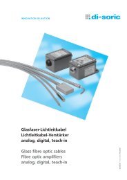
Infrared Amplifier Information<br />
There are two types of <strong>Pantron</strong> amplifiers, manual, (ex. model<br />
ISG-N24), which allows the user to manually adjust the ga<strong>in</strong><br />
sett<strong>in</strong>g, and automatic amplifiers, (ex. model ISG-A124.) The<br />
amplifier is the controller for the <strong>Pantron</strong> photo eyes and<br />
plugs <strong>in</strong>to an 11-p<strong>in</strong> socket. The transmitter and receiver<br />
photo eyes connect to this socket as well as the power supply<br />
for the amplifier and the output connections for the equipment<br />
to be controlled.<br />
The amplifier sends a modulated signal to the transmitter<br />
photo eye. The transmitter converts this signal <strong>in</strong>to an <strong>in</strong>frared<br />
beam of light, which is projected up to 100 feet. The <strong>in</strong>tensity<br />
of the <strong>in</strong>frared beam may be controlled to compensate for the<br />
environmental conditions of different applications. In a car<br />
wash, for example, the <strong>in</strong>tensity of the beam should be strong<br />
to penetrate the spray, soap, dirt, and fog. In an application<br />
where smaller objects are be<strong>in</strong>g detected, for <strong>in</strong>stance, on a<br />
conveyor, the <strong>in</strong>tensity of the beam should be lower so that the beam does not illum<strong>in</strong>ate the object and pass around the sides. The<br />
receiver photo eye detects this <strong>in</strong>frared beam of light and returns a signal to the amplifier. If the signal returned to the amplifier<br />
matches the correct frequency, then the amplifier reports that the photo eyes have visual contact. <strong>Inc</strong>orrect frequencies are ignored,<br />
which is helpful <strong>in</strong> reduc<strong>in</strong>g false signals due to extraneous light sources.<br />
On the back of the amplifiers, <strong>in</strong> addition to the quick disconnect p<strong>in</strong>s, there is a bank of four Dipswitches.<br />
These switches are used to set the features previously described. These sett<strong>in</strong>gs vary based<br />
upon the model of amplifier be<strong>in</strong>g used. When sett<strong>in</strong>g a <strong>Pantron</strong> automatic amplifier, the first two<br />
Dipswitches are used together to control the level of <strong>in</strong>tensity of the <strong>in</strong>frared beam. The third Dipswitch<br />
controls a feature known as light and dark mode. If dark mode is selected, the amplifier will<br />
register an output when the <strong>in</strong>frared beam is <strong>in</strong>terrupted. If light mode is selected, the output will rema<strong>in</strong><br />
ON until the beam is <strong>in</strong>terrupted. The fourth Dipswitch selects the frequency that the transmitter<br />
will use to transmit its beam.<br />
<strong>Pantron</strong> automatic amplifiers (ISG-Axx) have a special diagnostic function that enables a user to troubleshoot the photo eyes without<br />
technical assistance. The button on the face of the amplifier, when held for two seconds causes the amplifier to reset, but when<br />
it is only pushed briefly, it causes the amplifier to enter diagnostic mode. In diagnostic mode, the text on the right-hand side of the<br />
face of the amplifier is used as a reference to <strong>in</strong>terpret the amplifier’s report, which is delivered through a series of flash<strong>in</strong>g LED’s.<br />
Most <strong>Pantron</strong> manual amplifiers (ISG-Nxx) do not <strong>in</strong>clude a diagnostic mode.<br />
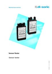
How to Use Diagnostic / Test Mode<br />
To put amplifier <strong>in</strong>to test mode, briefly press the Reset / Test Mode button and let it go. Hold<strong>in</strong>g this button will result <strong>in</strong> a full<br />
reset. If the follow<strong>in</strong>g LED’s flash, please note the <strong>in</strong>structions <strong>in</strong>cluded:<br />
No Signal Error: If the yellow OUTPUT STATUS LED flashes with the Alarm LED, the transmitter or receiver is either<br />
out of alignment or there is an obstruction prevent<strong>in</strong>g the two eyes from see<strong>in</strong>g each other. A clear signal should be possible<br />
if the photo eyes and their cables are not damaged.<br />
Signal Strength: If the green AUTOMATIC FUNCTION LED bl<strong>in</strong>ks by itself, the eyes can see each other and the number<br />
of bl<strong>in</strong>ks shows the strength of the <strong>in</strong>frared beam. (1 bl<strong>in</strong>k signifies the weakest beam and 10 is the strongest). If the<br />
signal strength is low, try clean<strong>in</strong>g the face of the photo eye and realign them.<br />
Transmitter Fail Error: If the upper yellow TRANSMIT CHANNEL LED bl<strong>in</strong>ks with the red Alarm LED, watch how<br />
fast it bl<strong>in</strong>ks. If it bl<strong>in</strong>ks faster than the Alarm LED, there is a short on the transmitter side. Check your cable connections to<br />
make sure they are correct. If it bl<strong>in</strong>ks the same slow speed as the Alarm LED, there is an open on the transmitter side.<br />
Check the cable, first where it connects to the amplifier, and second <strong>in</strong> any areas where the cable is exposed or where there<br />
are splices.<br />
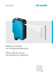
ISG-A124 series automatic amplifier<br />
Receiver Fail Error: If the lower yellow TRANSMIT CHANNEL LED bl<strong>in</strong>ks with the red Alarm LED, watch how fast it<br />
bl<strong>in</strong>ks. If it bl<strong>in</strong>ks faster than the Alarm LED, there is a short on the receiver side. Check your cable connections to make sure<br />
they are correct. If it bl<strong>in</strong>ks the same slow speed as the Alarm LED, there is an open on the receiver side. Check the cable,<br />
first where it connects to the amplifier, and second <strong>in</strong> any areas where the cable is exposed or where there are splices.<br />
7