Catalogo Implantologia 2013 English.pdf
- No tags were found...

You also want an ePaper? Increase the reach of your titles
YUMPU automatically turns print PDFs into web optimized ePapers that Google loves.
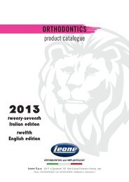
IMPLANTOLOGY<br />
product catalogue<br />
<strong>2013</strong><br />
seventh Italian edition<br />
sixth <strong>English</strong> edition<br />
ORTHODONTICS AND IMPLANTOLOGY<br />
Leone S.p.a. - Via P. a Quaracchi, 50<br />
50019 Sesto Fiorentino (Firenze) - Italy<br />
Phone +39.055.30.44.620 - Fax +39.055.30.44.05<br />
e-mail: info@leone.it - www.leone.it
In 1934 the history of Leone originated from a small handicraft activity and<br />
today it is an industrial reality of high technological and commercial level. The<br />
productive and industrial area spreads out over a surface of around 10.000 sq.<br />
m., where 125 people operate.<br />
CUSTOMER SERVICE<br />
LEONE is working non stop to satisfy the customer’s expectations and is represented<br />
with dealers in 60 countries. A careful pre-sale and post-sale customer<br />
assistance is provided by qualified technical and commercial staff to meet any<br />
requirement.<br />
WAREHOUSE<br />
Finished and semi-finished products are stocked and organized by vertical lift<br />
automatic cabinets allowing a rationalization of the space and a fully computer<br />
based processing of the orders.<br />
Standard orders are shipped within 24 hours in Italy and 5-6 working days in the<br />
foreign country.<br />
EDUCATION, TRAINING, UPGRADING<br />
Equipped with every multimedia device, the facility of 1000 sq.m is entirely dedicated<br />
to lectures and to the spreading of new therapeutic techniques. Training<br />
course, hands-on demonstrations and cultural events are being held for either<br />
Italian or foreign specialists.<br />
3
www.leone.it<br />
SUMMARY<br />
PROSTHETIC PROCEDURE<br />
DICLAIMER AND PREMISE 80<br />
Indirect technique:<br />
1. impression taking 81<br />
2. preparation of the dental cast 82-83<br />
3. preparation of the abutment 83..85<br />
4. selection, use and positioning of LEONE 360° anatomical abutments 85..87<br />
5. final positioning for standard and large platform 88-89<br />
6. final positioning for slim platform 89<br />
Direct technique:<br />
7. positioning and preparation of the abutment,<br />
impression taking for standard and large platform 90-91<br />
Other prosthetic solutions:<br />
8. Overdenture O-ring 91..94<br />
9. Bar-retained overdenture and screw-retained prosthesis 94..98<br />
10. Cast-on gold abutments: laboratory procedure 98..100<br />
11. Multi-Tech abutments: instructions for use 100-101<br />
12. Temporary abutments: application procedure 102..104<br />
LEONE MONOIMPLANTS FOR OVERDENTURE O-RING<br />
SURGICAL AND PROSTHETIC PROCEDURE<br />
DISCLAIMER AND IMPLANTO-PROSTHETIC TREATMENT PLANNING 106-107<br />
1. Preparation of the implant site 108-109<br />
2. Monoimplant packaging 110<br />
3. Insertion of the monoimplant 111-112<br />
4. Preparation of the removable prosthesis 113-114<br />
Photos courtesy of:<br />
- Dr. Salvatore Belcastro, Gubbio, Perugia, Italy<br />
- Dr. Irene Frezzato and Dr. Alberto Frezzato, Rovigo, Italy<br />
- Dr. Roberto Meli, Florence, Italy<br />
- Mr. Massimiliano Pisa, Florence, Italy<br />
- Dr. Leonardo Targetti, Florence, Italy<br />
- Dr. Renato Turrini, Lucca, Italy<br />
5
LEONE DENTAL IMPLANT SYSTEM<br />
www.leone.it<br />
LEONE DENTAL IMPLANT SYSTEM<br />
The Leone implant system offers a wide range of products that allows to choose the most<br />
adequate solution for the planned rehabilitation depending on the clinical situation and the<br />
prosthetic requirements.<br />
The distinctive feature of the system is a combination of two geometries: self-locking Morse<br />
taper connection and internal hexagon.<br />
The Morse taper ensures a remarkable mechanical stability, total absence of micro movements,<br />
a perfect bacterial seal and optimal distribution of masticatory loading. The hexagon enhances<br />
the resistance to torsional loading and guarantees the precise transfer of the angular position<br />
of the abutment between the dental office and the laboratory.<br />
The Leone Implant System is characterized by Platform Switching as a natural consequence of<br />
the taper connection.<br />
Regarding the implant macro-design, the LEONE implant system includes three different types<br />
of fixtures: the LEONE implants, featuring a cylindrical geometry, with a thread design in<br />
accordance with ISO standard and a hemispherical apex; the Max Stability implants, having a<br />
root-form geometry, a more aggressive thread design and a conical apex, suitable for poor bone<br />
density and fresh extraction sockets; the LEONE 6.5 short implant, with a minimised length, a<br />
thread with an even increased height and a flat apex, ideal for cases with limited vertical bone<br />
availability.<br />
All Leone implants are manufactured from medical grade 5 titanium and feature the HRS (High<br />
Rutile Surface) surface, obtained through an exclusive sandblasting process which produces a<br />
roughness Ra = 2.5 µm on the implant, favouring the activity of osteoblasts and ensuring a<br />
rapid osseointegration.<br />
LASER MARKED<br />
to guarantee<br />
the original product<br />
HRS SURFACE<br />
Due to the Morse taper implant-abutment connection, the Leone abutments do not need a retaining<br />
screw, they are solid, with no cavities. This feature, combined with the particular quality<br />
of the titanium used, allows the abutment to be easily customized either in the laboratory or<br />
directly in the oral cavity of the patient.<br />
A colour code is associated with each implant diameter and helps the user choose the relevant<br />
accessories and necessary tools for the following work phases.<br />
KEY TO DENTAL IMPLANTS<br />
GREEN<br />
For implant:<br />
Ø 3,3 mm<br />
YELLOW<br />
For implant:<br />
Ø 4,1 mm<br />
RED<br />
For implant:<br />
Ø 4,8 mm<br />
DARK<br />
GREEN<br />
For implant:<br />
Max Stability Ø 3,75 mm<br />
DARK<br />
YELLOW<br />
For implant:<br />
Max Stability Ø 4,5 mm<br />
FUCHSIA<br />
For implant:<br />
short 6.5<br />
6
www.leone.it<br />
LEONE DENTAL IMPLANTS<br />
DENTAL IMPLANTS<br />
Made of medical grade 5 titanium, HRS surface, self-locking Morse taper connection and internal hexagon.<br />
Mounted on a carrier, with an included biopolymer sealing cover cap, and packed in gamma-ray sterile glass<br />
vial. Cap removal from the inner holder and placement into the implant requires instrument Cat. 156-1003-00.<br />
Pack content: 1 implant and 1 cover cap<br />
DENTAL IMPLANT Ø 3.3 mm WITH COVER CAP<br />
Ø 3,3 mm 3,3 mm 3,3 mm 3,3 mm<br />
length 8 mm 10 mm 12 mm 14 mm<br />
110-3308-02 110-3310-02 110-3312-02 110-3314-02<br />
TOP LID<br />
SEALING CAP<br />
DENTAL IMPLANT Ø 4.1 mm WITH COVER CAP<br />
IMPLANT<br />
Ø 4,1 mm 4,1 mm 4,1 mm 4,1 mm<br />
length 8 mm 10 mm 12 mm 14 mm<br />
110-4108-02 110-4110-02 110-4112-02 110-4114-02<br />
INNER HOLDER<br />
COVER CAP<br />
DENTAL IMPLANT Ø 4.8 mm WITH COVER CAP<br />
Ø 4,8 mm 4,8 mm 4,8 mm 4,8 mm<br />
length 8 mm 10 mm 12 mm 14 mm<br />
110-4808-02 110-4810-02 110-4812-02 110-4814-02<br />
GLASS VIAL<br />
7
LEONE 6.5 SHORT IMPLANT<br />
www.leone.it<br />
LEONE 6.5 SHORT IMPLANT<br />
• Ideal for cases with limited vertical bone availability<br />
• To avoid complex bone grafting procedures<br />
• To minimize advanced surgical interventions<br />
(sinus lift, inferior alveolar nerve transposition)<br />
• To avoid sensitive anatomical structures with a high degree of safety<br />
• To increase patient’s acceptance due to reduced treatment time and costs<br />
LEONE 6.5 SHORT DENTAL IMPLANT WITH COVER CAP<br />
Made of medical grade 5 titanium. HRS surface, self-locking Morse taper connection and internal hexagon.<br />
Mounted on a carrier, with an included biopolymer sealing cover cap, and packed in gamma-ray sterile glass vial. Cap removal from the inner holder and<br />
placement into the implant requires instrument Cat. 156-1003-00.<br />
Pack content: 1 implant and 1 cover cap<br />
Ø<br />
length<br />
5 mm<br />
6,5 mm<br />
110-5065-02<br />
The cover cap supplied with the implant is yellow since it has the same<br />
internal connection as the standard 4,1 mm-diameter LEONE implant. This<br />
ensures absolute stability and mechanical resistance: extremely important<br />
issues in this particular case as the crown-implant ratio results to be increased.<br />
There is no need for special accessories: healing caps, transfers and<br />
abutments for the 4.1 mm connection with yellow colour code are to be used.<br />
• LENGTH<br />
• INCREMENTAL THREADS<br />
• FLAT APEX<br />
• IMPLANT THREAD<br />
reduced to 6.5 mm<br />
with diameter up to 5 mm<br />
for additional decrease of the implant’s length<br />
in comparison to LEONE standard implants the height of the implant<br />
thread is increased by 125%, the bone contact surface is comparable to<br />
the surface of an implant 4,1 mm in diameter and 8 mm long.<br />
The LEONE 6.5 short implant and the whole range of specific surgical<br />
instruments are featured by a FUCHSIA COLOUR-CODE.<br />
8
www.leone.it<br />
LEONE MAX STABILITY DENTAL IMPLANTS<br />
LEONE MAX STABILITY DENTAL IMPLANTS<br />
Max Stability dental implants feature an innovative external macro-design, formulated to obtain a<br />
high primary stability in cases where the implant site offers poor stability for fixtures with a classical<br />
design.<br />
The implant primary stability is evaluated by measuring the insertion torque values. In medium to<br />
poor bone quality they have over 50% higher insertion torque values compared to cylindrical implants<br />
with the same length and connection size.<br />
Max Stability implants Ø3,75 and Ø4,5 mm have the same internal connection as the Ø3,3 and<br />
Ø4,1 mm implants. The surgical procedure for the preparation of the implant site is also the same.<br />
Accordingly, the colour codes are also identical: GREEN for the Ø3,75 implants - YELLOW for the Ø4,5<br />
implants.<br />
Made of medical grade 5 titanium. HRS surface, self-locking Morse taper connection and internal<br />
hexagon.<br />
Mounted on a carrier, with an included biopolymer sealing cover cap, and packed in gamma-ray sterile<br />
glass vial. Cap removal from the inner holder and placement into the implant requires instrument<br />
Cat. 156-1003-00.<br />
Pack content: 1 implant and 1 cover cap<br />
LEONE MAX STABILITY DENTAL IMPLANTS Ø 3,75 mm WITH COVER CAP<br />
Ø 3,75 mm 3,75 mm 3,75 mm<br />
length 8 mm 10 mm 12 mm<br />
110-3808-02 110-3810-02 110-3812-02<br />
The cover cap supplied with the implant is<br />
green since it has the same internal connection<br />
as the standard 3.3 mm-diameter<br />
LEONE implant. Healing caps, transfers, and<br />
abutments for the 3.3 mm connection with<br />
green colour code are to be used.<br />
LEONE MAX STABILITY DENTAL IMPLANT Ø 4.5 mm WITH COVER CAP<br />
Ø 4,5 mm 4,5 mm 4,5 mm<br />
length 8 mm 10 mm 12 mm<br />
110-4508-02 110-4510-02 110-4512-02<br />
The cover cap supplied with the implant is<br />
yellow since it has the same internal connection<br />
as the standard 4,1 mm-diameter<br />
LEONE implant. Healing caps, transfers, and<br />
abutments for the 4.1 mm connection with<br />
yellow colour code are to be used.<br />
ROOT-FORM<br />
with conical apex facilitating the insertion process<br />
INCREMENTAL APICAL THREADS<br />
with increasing height<br />
THREAD DESIGN<br />
results in an over a 50% increase in thread height compared to cylindrical<br />
implants, leading to a considerable increase in primary stability as well<br />
as a gain in bone-implant contact surface area compared to cylindrical<br />
implants with the same length and connection size<br />
WHEN TO USE A LEONE MAX STABILITY IMPLANT<br />
In case of implant placement with poor bone quality<br />
The thread design and the apex profile allow good anchorage, even in<br />
the presence of reduced bone density.<br />
NOT FOR INSERTION IN D1 BONE<br />
In case of implant placement into fresh extraction sockets<br />
The geometry of the implant is ideal for the insertion in post-extraction<br />
sockets.<br />
In case of some advanced surgical interventions<br />
The implant apex, featuring a conical profile and incremental threads,<br />
facilitates the insertion process by reducing the risk of fractures and<br />
fenestrations.<br />
9
PLATFORM SWITCHING AND PLATFORMS OF THE LEONE IMPLANT SYSTEM<br />
www.leone.it<br />
PLATFORM SWITCHING<br />
The emergence profile of the Leone abutments features a smaller diameter than the maximum<br />
diameter of the implant neck. The “Platform Switching” concept involves several advantages<br />
like the shift of the area of the inflammatory infiltrate inwards (away from the crestal bone),<br />
a reduced perimeter to protect against the external agents, a larger amount of periimplant<br />
gingival soft tissue and therefore a better mucosa seal to protect the crestal bone.<br />
THE MEANING OF PLATFORM<br />
After the placement of the implant, thanks to the Platform<br />
Switching concept, the LEONE Implant System offers the possibility<br />
to select the diameter of the most appropriate abutment<br />
to the clinical situation. Specific healing caps and transfer<br />
are available for each platform that allow the achievement<br />
of excellent results in the conditioning of the soft tissues and<br />
impression taking.<br />
1 2<br />
3<br />
1<br />
2 3<br />
STANDARD PLATFORM<br />
The diameter is the SAME as the<br />
diameter of the implant neck.<br />
Indicated for standard treatments.<br />
Featured by Platform Switching.<br />
LARGE PLATFORM<br />
The diameter is LARGER than the diameter of the<br />
implant neck. Indicated when the tooth to be replaced<br />
is noticeably larger in comparison to the inserted<br />
implant. The aim is to enhance functionality and<br />
aesthetics. Featured by Platform Switching.<br />
SLIM PLATFORM<br />
The diameter is SMALLER than the<br />
diameter of the implant neck. Indicated<br />
in aesthetic areas with low gingival<br />
thickness.<br />
It allows the manufacture of a crown<br />
closing on the implant neck.<br />
KEY TO PROSTHETIC PRODUCTS<br />
Since the following groups of implants have the same implant-abutment connection size,<br />
the colour code for the choice of the prosthetic products is the following:<br />
for implants:<br />
for implants:<br />
GREEN Ø 3,3 mm<br />
YELLOW Ø 4,1 mm<br />
Max Stability Ø 3,75 mm<br />
Max Stability Ø 4,5 mm<br />
short 6.5<br />
RED<br />
for implants:<br />
Ø 4,8 mm<br />
10<br />
The pictures and indications illustrated in this literature have informative purpose only and they are not intended to replace the methods or procedures for diagnosis and treatment planning of the Dental Surgeon, Dentist and<br />
Dental Technician regarding the needs of each patient. Leone Spa disclaims any liability or any other obligation expressed or implied in this literature.
www.leone.it<br />
STANDARD PLATFORM<br />
SELF-LOCKING CAPS, LOW<br />
Made of medical grade 5 titanium.<br />
Single supplied on carrier and packed in gamma-ray sterilized glass<br />
vials. The caps are locked into the implant through the application of an<br />
impulsive force that activates the self-locking connection. They are used<br />
in place of the cover caps in cases of subcrestal implant placement or<br />
in place of the healing caps in cases of low gingival thickness (pages<br />
68..70). Use the special hex head extractor Cat. 156-1006-00 to unlock<br />
the connection. Use the instrument for cover cap Cat. 156-1003-00 for<br />
removal.<br />
Packs of 1<br />
for implant<br />
Ø platform 3,3 mm 4,1 mm 4,8 mm<br />
gingival height 1,5 mm 1,5 mm 1,5 mm<br />
133-3301-33 133-4101-41 133-4801-48<br />
STANDARD HEALING CAPS<br />
Made of medical grade 5 titanium.<br />
Single supplied ready on carrier, packed in gamma-ray sterile glass vial.<br />
Healing caps are locked in the implants by means of an impulsive force<br />
which activates the conical locking-taper connection. Use the special hex<br />
head extractor Cat. 156-1006-00 to unlock the connection.<br />
Packs of 1<br />
for implant<br />
Ø platform 3,3 mm 3,3 mm 3,3 mm<br />
gingival height 3 mm 5 mm 7 mm<br />
131-3303-33 131-3305-33 131-3307-33<br />
for implant<br />
Ø platform 4,1 mm 4,1 mm 4,1 mm<br />
gingival height 3 mm 5 mm 7 mm<br />
131-4103-41 131-4105-41 131-4107-41<br />
for implant<br />
Ø platform 4,8 mm 4,8 mm 4,8 mm<br />
gingival height 3 mm 5 mm 7 mm<br />
131-4803-48 131-4805-48 131-4807-48<br />
STANDARD TRANSFER<br />
Made of stainless steel.<br />
They are used for taking and sending the impression to the laboratory to<br />
reproduce the exact position of the implant on the dental cast.<br />
Packs of 1<br />
for implant<br />
Ø platform 3,3 mm 4,1 mm 4,8 mm<br />
gingival height 5 mm 5 mm 5 mm<br />
141-3305-33 141-4105-41 141-4805-48<br />
11
STANDARD PLATFORM<br />
www.leone.it<br />
STANDARD ABUTMENTS<br />
CYLINDER ABUTMENT<br />
Made of medical grade 5 titanium.<br />
The abutments are seated into the implants through the self-locking<br />
Morse taper connection and internal hexagon<br />
Packs of 1<br />
for implant<br />
Ø platform 3,3 mm 4,1 mm 4,8 mm<br />
height 10 mm 10 mm 10 mm<br />
120-3310-33 120-4110-41 120-4810-48<br />
15° PRE-INCLINED ABUTMENT<br />
25° PRE-INCLINED ABUTMENT<br />
for implant<br />
Ø platform 3,3 mm 4,1 mm 4,8 mm<br />
height 10 mm 10 mm 10 mm<br />
124-3303-01 124-4103-01 124-4803-01<br />
for implant<br />
Ø platform 3,3 mm 4,1 mm 4,8 mm<br />
height 10 mm 10 mm 10 mm<br />
124-3303-02 124-4103-02 124-4803-02<br />
25° ANGLED ABUTMENT<br />
for implant<br />
Ø platform 3,3 mm 4,1 mm 4,8 mm<br />
height 10 mm 10 mm 10 mm<br />
125-3303-33 125-4103-41 125-4803-48<br />
A try-in abutment in plastic material is available associated with each abutment herewith indicated (page 26)<br />
12
www.leone.it<br />
LEONE 360° ANATOMICAL ABUTMENTS<br />
LEONE 360° ANATOMICAL ABUTMENTS<br />
LEONE 360° anatomical abutments have got the ideal features to facilitate the prosthetic<br />
procedure during the customizing phase in the laboratory and the clinical procedures<br />
afterwards.<br />
The main innovation of this product, protected by an international patent, is the apical<br />
hexagon separated from the rest of the abutment: the free positioning to 360° on the dental<br />
cast makes it easy to achieve parallelism while taking advantage of the anatomical form of<br />
the abutments. Afterwards, through the activation of the self-locking conical connection, the<br />
abutment will join the hexagon directed in the selected position which will drive the clinician<br />
in the positioning on the patient with the maximum precision (pages 85..87).<br />
• LEONE 360° anatomical abutments are available either straight or angled at 15°or 25°<br />
to meet all demands for the prosthetic rehabilitation.<br />
A step on the angled abutment allows the activation of the connection by exerting a force<br />
arranged coaxially to the implant axis. A special flat tip (Cat. 156-1008-06) may be joined<br />
to the multi-purpose handle or the abutment beater thus assuring a stable support.<br />
15° 25°<br />
• The morphologic shape of the abutment portion to be cemented features an<br />
optimal inclination and two opposite plain faces to improve the position and<br />
the retention of the copings.<br />
• The preformed shoulder may be further customized. The angled anatomical<br />
abutments show the vestibular portion, the part with the higher aesthetical<br />
value, with a height lower than lingual.<br />
• The transmucousal portion is available in three heights for a precise adaptation to the thickness of the soft<br />
tissues.<br />
• LEONE 360° special try-in abutments are associated with this innovative product.<br />
They facilitate the choice of the most appropriate abutment in the laboratory thus avoiding the necessity of<br />
goods storage and the possibilities of mistake.<br />
The try-in abutments are manufactured from a plastic material, autoclavable and may also be used to test<br />
the transmucousal portion on the patient.<br />
13
LEONE 360° ANATOMICAL ABUTMENTS<br />
www.leone.it<br />
LEONE 360° ANATOMICAL ABUTMENTS<br />
Made of medical grade 5 titanium.<br />
They are seated into the implants through the self-locking Morse taper connection and internal hexagon.<br />
Packs of 1 abutment and 1 hexagon<br />
3 3 3<br />
for implant<br />
abutment shoulder<br />
minimum height<br />
1 mm 2 mm 3 mm<br />
STRAIGHT 129-3301-00 129-3302-00 129-3303-00<br />
15° ANGLED 129-3301-01 129-3302-01 129-3303-01<br />
25° ANGLED 129-3301-02 129-3302-02 129-3303-02<br />
3 3 3<br />
for implant<br />
abutment shoulder<br />
minimum height<br />
1 mm 2 mm 3 mm<br />
STRAIGHT 129-4101-00 129-4102-00 129-4103-00<br />
15° ANGLED 129-4101-01 129-4102-01 129-4103-01<br />
25° ANGLED 129-4101-02 129-4102-02 129-4103-02<br />
3 3 3<br />
for implant<br />
abutment shoulder<br />
minimum height<br />
1 mm 2 mm 3 mm<br />
STRAIGHT 129-4801-00 129-4802-00 129-4803-00<br />
15° ANGLED 129-4801-01 129-4802-01 129-4803-01<br />
25° ANGLED 129-4801-02 129-4802-02 129-4803-02<br />
HEXAGON FOR LEONE 360° ABUTMENTS<br />
3<br />
3 3<br />
Made of medical grade 5 titanium.<br />
Packs of 2<br />
for implant<br />
129-3300-00 129-4100-00 129-4800-00<br />
A try-in abutment in plastic material is available associated with each abutment herewith indicated (page 15)<br />
14
www.leone.it<br />
LEONE 360° TRY-IN ABUTMENT KIT<br />
160-0001-01<br />
LEONE 360° TRY-IN ABUTMENT KIT<br />
Manufactured from plastic material, autoclavable, in three<br />
colour-codes: green, yellow and red, to allow the immediate identification<br />
of the corresponding implant diameter.<br />
They are the exact replica of the LEONE 360° anatomical<br />
abutments but without the apical hexagon to test the most appropriate<br />
position for each specific case.<br />
Each try-in abutment is marked with a number useful for the<br />
placement in the proper space into the kit. A transparent template<br />
over the plastic case, shows the outlines and the catalogue code<br />
numbers of each corresponding titanium anatomical abutment to<br />
facilitate the ordering of the selected type.<br />
4 plastic try-in abutments for each type are contained in the kit<br />
to allow the choice in complex prosthetic rehabilitations. Only the<br />
inner tray is autoclavable.<br />
Kit content:<br />
4 try-in abutments each implant diameter and each shape:<br />
straight, angled at 15°and 25° and each shoulder height available<br />
(page 14), total 108 pcs<br />
160-0033-01<br />
REFILL - LEONE 360° TRY-IN ABUTMENT<br />
FOR IMPLANTS 3,3 AND MAX STABILITY 3,75<br />
Content:<br />
4 sets of try-in abutments for implant 3.3 and Max Stability 3,75, each type:<br />
straight, angled at 15°and 25° and each shoulder height available,<br />
total 36 pcs<br />
160-0041-01<br />
REFILL - LEONE 360° TRY-IN ABUTMENT<br />
FOR IMPLANTS 4,1, SHORT 6.5 AND MAX STABILITY 4,5<br />
Content:<br />
4 sets of try-in abutments for implant 4.1, LEONE 6.5 short implant and Max Stability 3,75, each type:<br />
straight, angled at 15°and 25° and each shoulder height available,<br />
total 36 pcs<br />
160-0048-01<br />
REFILL - LEONE 360° TRY-IN ABUTMENT FOR IMPLANTS 4,8<br />
Content: 4 sets of try-in abutments for implant 4.8 each type:<br />
straight, angled at 15°and 25° and each shoulder height available,<br />
total 36 pcs<br />
15
LARGE PLATFORM<br />
www.leone.it<br />
LARGE HEALING CAPS<br />
Made of medical grade 5 titanium. Single supplied on carrier, packed in<br />
gamma-ray sterile glass vial.<br />
Healing caps are locked into the implants by means of an impulsive force<br />
which activates the conical locking-taper connection.<br />
Use the specific hex-head extractor Cat. 156-1006-00 to unlock the<br />
connection.<br />
Packs of 1<br />
for implant<br />
Ø platform 4,5 mm 4,5 mm 4,5 mm<br />
gingival height 3 mm 5 mm 7 mm<br />
131-3303-45 131-3305-45 131-3307-45<br />
for implant<br />
Ø platform 5,5 mm 5,5 mm 5,5 mm<br />
gingival height 3 mm 5 mm 7 mm<br />
131-4103-55 131-4105-55 131-4107-55<br />
for implant<br />
Ø platform 6,0 mm 6,0 mm 6,0 mm<br />
gingival height 3 mm 5 mm 7 mm<br />
131-4803-60 131-4805-60 131-4807-60<br />
LARGE TRANSFER<br />
Made of stainless steel.<br />
They are used for taking and sending the impression to the laboratory to<br />
reproduce the exact position of the implant on the dental cast.<br />
Packs of 1<br />
for implant<br />
Ø platform 4,5 mm 5,5 mm 6,0 mm<br />
gingival height 5 mm 5 mm 5 mm<br />
141-3305-45 141-4105-55 141-4805-60<br />
16
www.leone.it<br />
LARGE PLATFORM<br />
LARGE ABUTMENTS<br />
CYLINDER ABUTMENT<br />
Made of medical grade 5 titanium.<br />
They are seated into the implants through the self-locking Morse taper<br />
connection and internal hexagon.<br />
Packs of 1<br />
for implant<br />
Ø platform 4,5 mm 5,5 mm 6,0 mm<br />
height 10 mm 10 mm 10 mm<br />
120-3310-45 120-4110-55 120-4810-60<br />
15° PRE-INCLINED ABUTMENT<br />
25° PRE-INCLINED ABUTMENT<br />
for implant<br />
Ø platform 4,5 mm 5,5 mm 6 mm<br />
height 10 mm 10 mm 10 mm<br />
124-3303-03 124-4103-03 124-4803-03<br />
for implant<br />
Ø platform 4,5 mm 5,5 mm 6 mm<br />
height 10 mm 10 mm 10 mm<br />
124-3303-04 124-4103-04 124-4803-04<br />
25° ANGLED ABUTMENT<br />
for implant<br />
Ø platform 4,5 mm 5,5 mm 6,0 mm<br />
height 10 mm 10 mm 10 mm<br />
125-3303-45 125-4103-55 125-4803-60<br />
A try-in abutment in plastic material is available associated with each abutment herewith indicated (page 26)<br />
17
SLIM PLATFORM<br />
www.leone.it<br />
SLIM HEALING CAPS<br />
Made of medical grade 5 titanium. Single supplied on carrier, packed in<br />
gamma-ray sterile glass vial.<br />
Healing caps are locked into the implants by means of a pressure exerted<br />
on the cap once the internal hexagon is correctly engaged.<br />
Use instrument Cat. 156-1003-00 for removal of the caps.<br />
Packs of 1<br />
for implant<br />
transmucosal Ø 3,3 mm 4,1 mm 4,8 mm<br />
gingival height 3 mm 3 mm 3 mm<br />
132-3303-33 132-4103-41 132-4803-48<br />
SLIM TRANSFER<br />
Made of stainless steel.<br />
They are used for taking and sending the impression to the laboratory to<br />
duplicate the exact position of the implant on the dental cast.<br />
Packs of 1<br />
for implant<br />
transmucosal Ø 3,3 mm 4,1 mm 4,8 mm<br />
gingival height 3 mm 3 mm 3 mm<br />
143-3303-33 143-4103-41 143-4803-48<br />
SLIM ABUTMENTS<br />
Made of medical grade 5 titanium. The abutments are connected to the implants through the self-locking Morse taper connection and internal hexagon.<br />
CYLINDER ABUTMENTS<br />
10° ANGLED DOUBLE ABUTMENTS<br />
for implant<br />
transmucosal Ø 2,2 mm 3,0 mm 3,7 mm<br />
height 10 mm 10 mm 10 mm<br />
120-3310-22 120-4110-30 120-4810-37<br />
for implant<br />
transmucosal Ø 2,2 mm 3,0 mm 3,7 mm<br />
height 10 mm 10 mm 10 mm<br />
127-3301-10 127-4101-10 127-4801-10<br />
A try-in abutment in plastic material is available associated with each abutment herewith indicated (page 26)<br />
18
www.leone.it<br />
MULTITECH ABUTMENTS<br />
MULTITECH ABUTMENTS<br />
MultiTech abutments are used to fabricate a fully patient-customized abutment through the realization of a customized part to be bonded on the central<br />
portion of the abutment. Use NIMETIC CEM (3M Espe), PANAVIA 21 (Kuraray Medical Inc.) adhesive materials for bonding.<br />
The customized abutment portion can be performed under the following options (pages 100-101):<br />
• with CAD/CAM technology by taking a scan of the seated abutment on the dental cast and modelling of the customized abutment portion with a<br />
specific software. The fabrication is performed in the laboratory with a specific Computer-Assisted Machine or by a specialized production centre<br />
upon the receipt of the data file;<br />
• with the traditional method by using a pre-fabricated burn-out coping placed on the abutment, adjustment and modelling with wax and/or acrylic<br />
and fabrication of the customized abutment portion through casting.<br />
Burn-out coping<br />
Sandblasted bonding emergence portion<br />
for the anchorage of the customized<br />
abutment to enhance the bond retention<br />
HYBRID<br />
TITANIUM/ZIRCONIA<br />
ABUTMENT<br />
Platform Switching<br />
self-locking Morse taper connection and<br />
internal hexagon<br />
TITANIUM/METAL<br />
ABUTMENT<br />
MULTITECH ABUTMENTS<br />
Made of medical grade 5 titanium, they are seated into the implants through the self-locking Morse taper connection and internal hexagon.<br />
The bondable emergence portion of the abutment, which is entirely sandblasted, is available in two heights.<br />
Packs of 1 abutment + 2 burn-out copings<br />
for implant<br />
bonding portion 4 mm 8 mm 4 mm 8 mm 4 mm 8 mm<br />
121-3304-00 121-3308-00 121-4104-00 121-4108-00 121-4804-00 121-4808-00<br />
19
TEMPORARY ABUTMENTS AND CAST-ON GOLD ABUTMENTS<br />
www.leone.it<br />
TEMPORARY ABUTMENTS<br />
The LEONE temporary abutments are used for provisional restorations (they<br />
have the emergence profile of the Standard platform).<br />
They are connected to the implants in the same way as the titanium<br />
abutments, using the same instruments. The Morse taper connection<br />
guarantees a suitable tightness for use over a limited period of time allowing<br />
an easy removal of the abutment whenever advisable.<br />
Made of a special ultra-polymer - a PEEK polymer featuring very high<br />
mechanical properties - highly biocompatible, easily prepable and<br />
radiotransparent.<br />
They are seated into the implants through the self-locking Morse taper<br />
connection and internal hexagon.<br />
Sterilizable in autoclave.<br />
Packs of 1<br />
for implant<br />
height 10 mm 10 mm 10 mm<br />
STRAIGHT 161-3310-00 161-4110-00 161-4810-00<br />
15° ANGLED 161-3310-15 161-4110-15 161-4810-15<br />
CAST-ON GOLD ABUTMENTS<br />
Titanium integral abutments may not be able to fulfil the prosthetic requirements in specific situations,<br />
such as in cases with more than 25° of inclination, or with very thin soft tissues, etc.<br />
In these cases, a cast-on abutment accurately reproducing the connection part may be the right solution.<br />
Thanks to the cast-on process, these abutments allow to get a totally customized emergence.<br />
Since the self-locking connection is featured by a highly matching precision with the implant female, it<br />
is mandatory not to modify the self-locking conical part for any reason and in every laboratory operations.<br />
The abutment is made of gold alloy (Au 60%, Pt 19%, Pd 20%, Ir 1%), a non-oxidizing gold-based alloy<br />
specific for cast-on procedures.<br />
This alloy has high mechanical properties but, due to its non-oxidation properties and its specific thermal<br />
coefficient of expansion, it does not allow to place ceramics directly on it.<br />
The emergence portion and the abutment body may be dental casted on the gold abutment to obtain a<br />
customized shape; three burn-out copings are available, in order to easily reproduce the three platforms<br />
of the LEONE implant system, Standard, Large and Slim. Each coping is provided with a cylindrical female<br />
part to perfectly fit the gold abutment.<br />
It is however possible to perform a wax-up without the use of the coping and get totally customized restorations<br />
Suitable dental casting alloys: high noble alloys, precious metal alloys with a minimum content of gold<br />
and platinum group of metals with a range of 25%, palladium based alloys with a minimum palladium<br />
range of 50%.<br />
Caution: the gold alloy (Au 60%, Pt 19%, Pd 20%, Ir 1%) used in the production of these abutments<br />
cannot be cast-on with CrCo and NiCr alloys.<br />
Pack content:<br />
1 abutment, 1 standard coping, 1 large coping and 1 slim coping<br />
for implant<br />
128-3300-00 128-4100-00 128-4800-00<br />
A try-in abutment in plastic material is available associated with each abutment herewith indicated (page 26)<br />
20<br />
The pictures and indications illustrated in this literature have informative purpose only and they are not intended to replace the methods or procedures for diagnosis and treatment planning of the Dental Surgeon, Dentist<br />
and Dental Technician regarding the needs of each patient. Leone Spa disclaims any liability or any other obligation expressed or implied in this literature.
www.leone.it<br />
O-RING OVERDENTURE ABUTMENTS<br />
STANDARD ABUTMENTS FOR O-RING OVERDENTURE<br />
Made of medical grade 5 titanium. The abutments for overdenture are fixed to the implant by means of an impulsive force which activates the conical<br />
locking-taper connection. Also available 15° angled to help achieve parallelism.<br />
Pack content: 1 abutment, 1 housing, 1 O-ring<br />
for implant<br />
gingival height 1,5 mm 3 mm 5 mm 7 mm<br />
STRAIGHT 123-3301-00 123-3303-00 123-3305-00 123-3307-00<br />
15° ANGLED 123-3301-15 123-3303-15 123-3305-15 123-3307-15<br />
15°<br />
for implant<br />
gingival height 1,5 mm 3 mm 5 mm 7 mm<br />
STRAIGHT 123-4101-00 123-4103-00 123-4105-00 123-4107-00<br />
15° ANGLED 123-4101-15 123-4103-15 123-4105-15 123-4107-15<br />
for implant<br />
gingival height 1,5 mm 3 mm 5 mm 7 mm<br />
STRAIGHT 123-4801-00 123-4803-00 123-4805-00 123-4807-00<br />
15° ANGLED 123-4801-15 123-4803-15 123-4805-15 123-4807-15<br />
123-0002-00<br />
HOUSING WITH O-RING<br />
Made of medical grade 5 titanium.<br />
Outer diameter: 5,4 mm, height: 3,1 mm.<br />
Pack of 1<br />
123-0003-00<br />
MICRO HOUSING WITH O-RING<br />
Made of medical grade 5 titanium.<br />
Outer diameter: 4,2 mm, height: 2,8 mm.<br />
Pack of 1<br />
123-0001-00<br />
ELASTOMERIC O-RING<br />
Pack of 2<br />
123-0001-01<br />
ELASTOMERIC MICRO O-RING<br />
Pack of 2<br />
A try-in abutment in plastic material is available associated with each abutment herewith indicated (page 26)<br />
21
STANDARD ABUTMENTS LEONE 360° FOR SCREW-RETAINED PROSTHESIS<br />
www.leone.it<br />
STANDARD ABUTMENTS FOR SCREW-RETAINED PROSTHESIS<br />
The abutments for screw-retained prosthesis have a tapered top with an internal thread allowing<br />
the connection of a prosthesis by screw retention. They are indicated for screw-retained prosthesis<br />
(hybrid prosthesis or bridges, such as Toronto Bridge) as well as for bar-retained overdentures.<br />
The abutments for screw-retained prosthesis are available in straight versions as well as in 15°<br />
or 25° angled versions to help achieve parallelism for non-parallel implants.<br />
The angled abutments are characterized by the LEONE 360° connection, protected by an international<br />
patent, having an apical hexagon separated from the rest of the abutment. The free<br />
positioning to 360° of the abutment on the dental cast makes it easy to achieve parallelism,<br />
whereas the permanent connection of the hexagon in the selected position allows an accurate<br />
positioning of the abutment in the mouth.<br />
The package of all abutments for screw-retained prosthesis include two different burn-out<br />
copings, a standard burn-out coping and a high burn-out coping. This simplifies the preparation<br />
of the definite metallic framework which can be obtained by a casting process using a metallic<br />
alloy at technician’s option. In this way the dental casting phase with waxes at the abutment’s<br />
interface is avoided ensuring a higher precision of the final restoration.<br />
• The standard burn-out coping (height: 4 mm)<br />
is designed for the realization of traditional bar-retained overdentures.<br />
• The high burn-out coping (height: 10 mm)<br />
is suitable for the realization of milled bars or screw-retained prosthesis. Its height can be<br />
cut back: a step on the external surface shows the shortening limit.<br />
• The standard connecting screw is designed for the standard burn-out coping and the<br />
gold coping.<br />
• The high head connecting screw is designed for the high burn-out coping or, in general,<br />
for high frameworks.<br />
22
www.leone.it<br />
STANDARD ABUTMENTS LEONE 360° FOR SCREW-RETAINED PROSTHESIS<br />
STANDARD ABUTMENTS FOR SCREW-RETAINED PROSTHESIS<br />
Made of medical grade 5 titanium. They are fixed to the implants through the self-locking Morse taper connection and internal hexagon.<br />
Pack content:<br />
1 abutment, 1 hexagon (for the angled ones only), 1 standard burn-out coping, 1 standard connecting screw, 1 high burn-out coping, 1 high head<br />
connecting screw<br />
for implant<br />
gingival height 1,5 mm 3 mm 5 mm 7 mm<br />
STRAIGHT 126-3301-01 126-3303-01 126-3305-01 126-3307-01<br />
15° ANGLED 126-3303-15 126-3305-15<br />
25° ANGLED 126-3303-25 126-3305-25<br />
15°<br />
for implant<br />
gingival height 1,5 mm 3 mm 5 mm 7 mm<br />
STRAIGHT 126-4101-01 126-4103-01 126-4105-01 126-4107-01<br />
15° ANGLED 126-4103-15 126-4105-15<br />
25° ANGLED 126-4103-25 126-4105-25<br />
25°<br />
for implant<br />
gingival height 1,5 mm 3 mm 5 mm 7 mm<br />
STRAIGHT 126-4801-01 126-4803-01 126-4805-01 126-4807-01<br />
15° ANGLED 126-4803-15 126-4805-15<br />
25° ANGLED 126-4803-25 126-4805-25<br />
A try-in abutment in plastic material is available associated with each abutment herewith indicated (page 26)<br />
23
ACCESSORIES FOR ABUTMENTS FOR SCREW-RETAINED PROSTHESIS<br />
www.leone.it<br />
STANDARD CONNECTING SCREW FOR SCREW-RETAINED<br />
PROSTHESIS<br />
Made of medical grade 5 titanium.<br />
Diameter: 2 mm; length: 4,5 mm.<br />
Pack of 1<br />
126-0001-00<br />
HIGH HEAD CONNECTING SCREW<br />
FOR SCREW-RETAINED PROSTHESIS<br />
Made of medical grade 5 titanium.<br />
Diameter: 2 mm; length: 6 mm.<br />
Pack of 1<br />
126-0001-06<br />
ADAPTER FOR CONNECTING SCREW<br />
Made of stainless steel. It is used joined to the hand-screw driver to<br />
connect the bar or the screw-retained prosthesis to the abutment.<br />
Length: 15 mm.<br />
Pack of 1 126-0002-00<br />
GOLD COPING FOR ABUTMENT<br />
FOR SCREW-RETAINED PROSTHESIS<br />
Made of golden alloy (Au 60%, Pt 19%, Pd 20%, Ir 1%), suitable for<br />
casting-on processes onto the bar.<br />
Packs of 1<br />
for implant<br />
126-0003-33 126-0003-41 126-0003-48<br />
TITANIUM COPINGS<br />
FOR ABUTMENTS FOR SCREW-RETAINED PROSTHESIS<br />
Made of medical grade 5 titanium.<br />
They allow the fixing of provisional and definitive screw-retained<br />
prosthesis to the abutments.<br />
Height: 10 mm.<br />
Packs of 2<br />
for implant<br />
126-0010-33 126-0010-41 126-0010-48<br />
TRANSFER FOR ABUTMENT<br />
FOR SCREW-RETAINED PROSTHESIS<br />
Made of stainless steel. They are used for impression taking on the<br />
abutments for screw-retained prosthesis already fixed to the implants to<br />
precisely reproduce the final position of the abutments on the dental cast.<br />
Packs of:<br />
1 transfer, 1 protective cap, 1 standard connecting screw<br />
for implant<br />
height 10 mm 10 mm 10 mm<br />
144-3310-00 144-4110-00 144-4810-00<br />
24
www.leone.it<br />
ACCESSORIES FOR ABUTMENTS FOR SCREW-RETAINED PROSTHESIS AND PROSTHETIC INSTRUMENTS<br />
ANALOGS FOR ABUTMENT<br />
FOR SCREW-RETAINED PROSTHESIS<br />
Made of stainless steel, colour-coded for easy identification.<br />
They are used in the dental cast to precisely reproduce the final position<br />
of the abutments for screw-retained prosthesis.<br />
Pack of 1<br />
for implant<br />
length 15 mm 15 mm 15 mm<br />
STRAIGHT 146-3315-00 146-4115-00 146-4815-00<br />
15° ANGLED 146-3315-15 146-4115-15 146-4815-15<br />
LONG WAXING SCREW<br />
Made of stainless steel. During wax modelling on the abutment for the<br />
screw-retained prosthesis, it allows the preparation of a channel of<br />
adequate dimensions for the seating of the connecting screw. Length:<br />
20 mm<br />
Packs of 5 126-0020-05<br />
156-0015-00<br />
ORGANIZER WITH BURS FG FOR ABUTMENTS<br />
Kit content:<br />
2 burs FG tungsten short tip Ø 1.2 mm Cat. 153-1221-02<br />
2 burs FG tungsten long tip Ø 1.2 mm Cat. 153-1235-02<br />
2 burs FG diamond-cut Ø 1.6 mm Cat. 153-1610-01<br />
2 burs FG diamond-cut Ø 1.8 mm Cat. 153-1810-01<br />
BURS FG FOR ABUTMENTS<br />
They are used in combination with a turbine for milling the<br />
abutments in the mouth.<br />
Packs of 1<br />
BUR FG TUNGSTEN<br />
short tip<br />
long tip<br />
BUR FG DIAMOND-CUT<br />
Ø 1,2 Ø 1,2<br />
153-1221-02 153-1235-02<br />
Ø 1,6 Ø 1,8<br />
153-1610-01 153-1810-01<br />
25
TRY-IN ABUTMENTS<br />
www.leone.it<br />
160-0001-02<br />
KIT OF TRY-IN ABUTMENTS<br />
SLIM, STANDARD, LARGE<br />
Manufactured from plastic material, autoclavable, in three<br />
colour-codes: green, yellow and red, to allow the immediate identification<br />
of the corresponding implant diameter.<br />
They are the exact replica of all the Leone abutments, with exception<br />
for the 360° abutments for which a special kit has been<br />
reserved (page 15).<br />
Each try-in abutment is marked with a number useful for the placement<br />
in the proper space into the kit. A transparent template<br />
over the plastic case, shows the outlines and the catalogue code<br />
numbers of each corresponding titanium anatomical abutment to<br />
facilitate the ordering of the selected type.<br />
4 plastic try-in abutments for each type are contained in the kit<br />
to allow the choice in complex prosthetic rehabilitations. Only the<br />
inner tray is autoclavable.<br />
Kit content:<br />
4 try-in abutments each implant diameter in 27 shapes,<br />
total 324 pcs<br />
160-0033-02<br />
REFILL FOR TRY-IN ABUTMENTS SLIM STANDARD LARGE FOR IMPLANT 3.3<br />
AND MAX STABILITY IMPLANT 3,75<br />
Content:<br />
4 sets of try-in abutments, 27 shapes each set, for implant 3.3 and Max Stability implants diameter 3,75<br />
Total 108 pcs<br />
160-0041-02<br />
REFILL FOR TRY-IN ABUTMENTS SLIM STANDARD LARGE FOR IMPLANT 4.1<br />
AND LEONE 6.5 SHORT IMPLANT AND MAX STABILITY IMPLANT 4,5<br />
Content:<br />
4 sets of try-in abutments, 27 shapes each set, for implant 4.1 mm in diameter,<br />
LEONE 6.5 short implant and Max Stability implants diameter 4,5.<br />
Total 108 pcs<br />
160-0048-02<br />
REFILL FOR TRY-IN ABUTMENTS SLIM STANDARD LARGE FOR IMPLANT 4.8<br />
Content:<br />
4 sets of try-in abutments, 27 shapes each set, for implant 4.8.<br />
Total 108 pcs<br />
26
www.leone.it<br />
PROSTHETIC ACCESSORIES<br />
ANALOGS<br />
Made of stainless steel. Designed to be used in the laboratory on dental casts to faithfully duplicate the position of the implant.<br />
With colour-code marking for easy identification. Available in two versions: standard and long (more retentive).<br />
Pack content: 1 analog, 1 pin, 1 bar for the extraction of the abutment.<br />
for implant<br />
Ø 3,3 mm 4,1 mm 4,8 mm<br />
length 8 mm 8 mm 8 mm<br />
142-3308-00 142-4108-00 142-4808-00<br />
for implant<br />
Ø 3,3 mm 4,1 mm 4,8 mm<br />
length 12 mm 12 mm 12 mm<br />
142-3312-00 142-4112-00 142-4812-00<br />
HANDLE FOR ABUTMENTS<br />
Made of medical grade 5 titanium. It is used for the milling of the abutment either in the laboratory or in the dental office.<br />
for implant<br />
inner cone Ø 2,2 mm 3,0 mm 3,7 mm<br />
156-1007-33 156-1007-41 156-1007-48<br />
27
SURGICAL INSTRUMENTS<br />
www.leone.it<br />
KEY TO SURGICAL INSTRUMENTS<br />
GREEN<br />
for implants:<br />
Ø 3,3 mm<br />
YELLOW<br />
for implants:<br />
Ø 4,1 mm<br />
RED<br />
for implants:<br />
Ø 4,8 mm<br />
DARK<br />
GREEN<br />
for implants:<br />
Max Stability Ø 3,75 mm<br />
DARK<br />
YELLOW<br />
for implants:<br />
Max Stability Ø 4,5 mm<br />
FUCHSIA<br />
for implants:<br />
short 6.5<br />
BLUE<br />
Stands for GENERAL-PURPOSE.<br />
Instruments and products suitable for all dental implant diameters<br />
156-0014-00<br />
ORGANIZER WITH CIRCULAR MUCOSA PUNCH<br />
Kit content:<br />
1 pc circular mucosa punch Ø 3.3 mm Cat. 151-3315-20<br />
1 pc circular mucosa punch Ø 4.1 mm Cat. 151-4115-20<br />
1 pc circular mucosa punch Ø 4.8 mm Cat. 151-4815-20<br />
1 pc measuring pin for gingival height Cat. 156-2004-00<br />
Supplied non sterile, instruments must be sterilised in autoclave before use.<br />
CIRCULAR MUCOSA PUNCH FOR CONTRA ANGLE<br />
Made of medical grade 5 titanium. Intended for use with a contra angle set at<br />
a low speed, it allows to punch the mucosa according to the selected implant<br />
diameter.<br />
The instruments are supplied non sterile and must be sterilised in the autoclave<br />
before use.<br />
Packs of 1<br />
for implant<br />
151-3315-20 151-4115-20 151-4815-20<br />
151-0001-00<br />
POSITIONER FOR DEPTH INDICATOR<br />
Made of anodized aluminium.<br />
Designed to be used during the preparation of the implant site, it allows the<br />
right placement of the depth indicator on the drills.<br />
Supplied non sterile, sterilise in autoclave before use.<br />
Pack content: 1 seating depth gauge and 4 packs depth indicator<br />
(one for each diameter available)<br />
DEPTH INDICATORS<br />
The elastomer ringlets are to be applied on the drill to better visualize the drilling<br />
depth. Supplied non sterile, the ringlets must be sterilised in the autoclave<br />
before use.<br />
Single use.<br />
Packs of 10<br />
for drill<br />
Ø 2,2 mm 151-0000-01<br />
Ø 2,8 mm 151-0000-02<br />
Ø 3,5 mm 151-0000-03<br />
Ø 4,2 mm 151-0000-04<br />
28
www.leone.it<br />
SURGICAL INSTRUMENTS<br />
BURS AND DRILLS<br />
Made of stainless steel. Diameter, length and depth marks are indicated on the body. Supplied non-sterile, burs and drills must be sterilised in autoclave<br />
before use. Replace drills used more than 20 times or in case of worn out cutting edges.<br />
Packs of 1<br />
ROUND BUR<br />
Designed to prepare the hole on the<br />
bone ridge as a guide for the drills.<br />
PILOT DRILL<br />
Indicated to drill the implant site. The 5 depth marks on the drill<br />
corresponding to the implant lengths (6,5-8-10-12-14 mm) enable<br />
the clinician to reach the relevant depth.<br />
Max speed: 800 rpm.<br />
short<br />
long<br />
for implant<br />
Ø<br />
1,9 mm<br />
2,2 mm 2,2 mm<br />
14<br />
12<br />
10<br />
8<br />
6.5<br />
length<br />
34 mm<br />
33 mm 39 mm<br />
151-1934-01<br />
151-2233-12 151-2241-12<br />
TWIST DRILL<br />
These drills are used in progression to allow the widening of the implant site up to the relevant size. The 5 depth marks on the drill<br />
corresponding to the implant lengths (6,5-8-10-12-14 mm) enable the clinician to reach the relevant depth.<br />
Max speed: diameter 2.8 mm 600 rpm; diameter 3.5 mm 500 rpm; diameter 4.2 mm 400 rpm.<br />
short long short long short long<br />
for implant<br />
Ø 2,8 mm 2,8 mm 3,5 mm 3,5 mm 4,2 mm 4,2 mm<br />
length 33 mm 39 mm 33 mm 39 mm 33 mm 39 mm<br />
151-2833-13 151-2841-13 151-3533-13 151-3541-13 151-4233-13 151-4241-13<br />
29
SURGICAL INSTRUMENTS<br />
www.leone.it<br />
COUNTERSINK<br />
Suitable to shape the osteotomy for the implant neck at the end of the<br />
surgical sequence.<br />
Thanks to its self-centering multi-blade geometry, it performs a perfectly<br />
coaxial and precise countersinking hole.<br />
Maximum speed: 300 rpm.<br />
for implant<br />
Ø 3,3 mm 4,1 mm 4,8 mm<br />
length 33 mm 33 mm 33 mm<br />
151-3333-24 151-4133-24 151-4833-24<br />
DRILLS FOR LEONE 6.5 SHORT IMPLANT<br />
With integrated depth stop at 6.5 mm.<br />
The 3,5 mm twist drill has got the crestal countersink integrated.<br />
These drills are used in progression to allow the widening of the<br />
implant site up to the LEONE 6.5 short implant diameter.<br />
Max speed:<br />
PILOT - diameter 2.2 mm 800 rpm;<br />
TWIST - diameter 2.8 mm 600 rpm;<br />
TWIST - diameter 3.5 mm 500 rpm.<br />
PILOT TWIST TWIST<br />
for implant<br />
Ø 2,2 mm 2,8 mm 3,5 mm<br />
length 33 mm 33 mm 33 mm<br />
151-2233-65 151-2833-65 151-3533-65<br />
TWIST DRILLS FOR HARD BONE<br />
Specifically developed for LEONE Max Stability implants, these twist drills are to be used at the end of the surgical sequence only with hard bone, in order<br />
to avoid excessive insertion torque forces.<br />
Made of stainless steel. The 5 depth marks (6.5-8-10-12-14 mm) on the drilling body enable the clinician to reach the desired depth.<br />
Two colour-coded marks, rather than one single mark, are visible on the drill’s stem and clearly distinguish them from other twist drills.<br />
Max speed: 500 rpm for implant Ø 3,75 mm; 400 rpm for implant Ø 4,5 mm.<br />
Supplied non-sterile.<br />
short long short long<br />
for implant<br />
length 33 mm 39 mm 33 mm 39 mm<br />
151-3133-13 151-3141-13 151-3833-13 151-3841-13<br />
30
www.leone.it<br />
SURGICAL INSTRUMENTS<br />
DRILLS WITH DEPTH STOP<br />
A drill system with depth stops, specific for the LEONE implant system. The system provides accurate<br />
drilling with depth control during the preparation of the implant site, especially in case of<br />
reduced visibility of the surgical area or proximity to sensitive anatomical structures.<br />
STOP<br />
The drills present a depth stop, which is an integral part of the drill, stopping the osteotomy at the<br />
level of the bone crest.<br />
The integrated depth stop determines, for each drill diameter, one specific drill for each implant<br />
length.<br />
Besides the cylindrical cutting portion, each twist drill has the crestal countersink integrated in<br />
order to shape the coronal portion of the osteotomy for the implant neck.<br />
The drills are available only in the short version. A drill extension for situations where longer instruments<br />
are needed is available.<br />
The drills with depth stop are made of stainless steel. The corresponding drilling depth is indicated<br />
on the stem. Supplied non-sterile, they must be sterilised in autoclave before use.<br />
Replace drills used more than 20 times or in case of worn out cutting edges.<br />
Packs of 1<br />
DRILL EXTENSION<br />
Made of stainless steel.<br />
Allows to extend the total length of the drill.<br />
Supplied non-sterile, sterilise in autoclave before use.<br />
156-1019-00<br />
PILOT DRILL WITH DEPTH STOP<br />
Max speed: 800 rpm.<br />
for implant<br />
Ø 2,2 mm 2,2 mm 2,2 mm 2,2 mm<br />
drilling depth 8 mm 10 mm 12 mm 14 mm<br />
151-2208-12 151-2210-12 151-2212-12 151-2214-12<br />
31
SURGICAL INSTRUMENTS<br />
www.leone.it<br />
TWIST DRILLS WITH DEPTH STOP<br />
These drills are used in progression to allow the widening of the implant site up to the relevant size.<br />
There is a colour-coded mark on the stem to allow the identification of the drill diameter.<br />
Each drill has the crestal countersink integrated.<br />
Max speed:<br />
- diameter 2,8 mm 600 rpm<br />
- diameter 3,5 mm 500 rpm<br />
- diameter 4,2 mm 400 rpm<br />
TWIST DRILL<br />
WITH DEPTH STOP Ø 2,8<br />
TWIST DRILL<br />
WITH DEPTH STOP Ø 3,5<br />
for implant<br />
Ø 2,8 mm 2,8 mm 2,8 mm 2,8 mm<br />
drilling depth 8 mm 10 mm 12 mm 14 mm<br />
151-2808-13 151-2810-13 151-2812-13 151-2814-13<br />
TWIST DRILL<br />
WITH DEPTH STOP Ø 4,2<br />
for implant<br />
Ø 3,5 mm 3,5 mm 3,5 mm 3,5 mm<br />
drilling depth 8 mm 10 mm 12 mm 14 mm<br />
151-3508-13 151-3510-13 151-3512-13 151-3514-13<br />
for implant<br />
Ø 4,2 mm 4,2 mm 4,2 mm 4,2 mm<br />
drilling depth 8 mm 10 mm 12 mm 14 mm<br />
151-4208-13 151-4210-13 151-4212-13 151-4214-13<br />
32
www.leone.it<br />
SURGICAL INSTRUMENTS<br />
TAP FOR LEONE DENTAL IMPLANTS Ø 3,3 - Ø 4,1 - Ø 4,8<br />
Made of stainless steel. Designed for the preparation of the implant site with high bone density.<br />
The elastomer ring on the octagonal basis allows the connection with the instruments.<br />
Supplied non sterile. Sterilise in the autoclave before use.<br />
short long short long short long<br />
for implant<br />
Ø 3,3 mm 3,3 mm 4,1 mm 4,1 mm 4,8 mm 4,8 mm<br />
length 21 mm 28 mm 21 mm 28 mm 21 mm 28 mm<br />
152-3321-00 152-3328-00 152-4121-00 152-4128-00 152-4821-00 152-4828-00<br />
TAP FOR LEONE 6.5 SHORT IMPLANT<br />
Tap “A”<br />
Tap “B”<br />
Made of stainless steel. The use of the tap “A” is essential with any kind of bone<br />
for the placement of the short implant 6.5. The bone tap “B” is suitable with<br />
high bone density and essential to be used after tapping with bone tap “A”. The<br />
elastomer ring on the octagonal basis allows the connection with the instruments.<br />
Two fuchsia colour-coded marks are present on the tap “B“’s stem to differentiate<br />
it from the bone tap “A”.<br />
Supplied non sterile.<br />
Sterilise in the autoclave before use.<br />
for implant<br />
Ø 5 mm 5 mm<br />
length 21 mm 21 mm<br />
152-5021-01 152-5021-02<br />
CONNECTING RINGS<br />
Replacement part for taps and instruments.<br />
Made of elastomer material.<br />
Packs of 5<br />
152-0000-01<br />
152-0000-02<br />
152-0000-03<br />
152-0000-04<br />
156-1002-02<br />
33
SURGICAL INSTRUMENTS<br />
www.leone.it<br />
MEASURING PIN FOR GINGIVAL HEIGHT<br />
Made of medical grade 5 titanium. Diameter: 2.2 mm, with a hole for the placement of a safety leash. It is used to measure<br />
the height of the soft tissues and ascertain parallelism, during the preparation of the implant site, immediately after the<br />
application of the pilot drill. For monoimplants and implants. Supplied non sterile.<br />
Sterilise in the autoclave before use.<br />
156-2004-00<br />
PARALLELING PIN<br />
Made of medical grade 5 titanium. Dimensions of the two ends: 2.2 mm and 2.8 mm in diameter.<br />
With a hole for the placement of a safety leash. Designed to be used during the preparation of the implant site to ascertain<br />
parallelism with natural teeth and/or with adjacent implant sites. For monoimplants and implants. Supplied non sterile.<br />
Sterilise in the autoclave before use.<br />
156-2001-00<br />
DEPTH GAUGE<br />
Made of medical grade 5 titanium. With a hole for the placement of a safety leash. Designed to be used during the<br />
preparation of the implant site to verify the depth. For monoimplants and implants.<br />
Supplied non sterile.<br />
156-2002-00<br />
HAND SCREWDRIVER<br />
standard<br />
large<br />
Made of medical grade 5 titanium. Designed for use with the tap to create a thread in the implant site and<br />
afterwards to screw the implant into the bone. It fits over the tap or the implant carrier and it can be used<br />
with the specially provided extension. With a hole for the placement of a safety leash. Supplied non sterile.<br />
Sterilise in the autoclave before use.<br />
156-1001-00 156-1001-01<br />
EXTENSION<br />
Made of medical grade 5 titanium. It is used to connect the hand screwdriver or the ratchet with other instruments like tap,<br />
carrier etc. The elastomer ring on the octagonal basis allows the connection with the hand instruments.<br />
Supplied non sterile. Sterilise in the autoclave before use.<br />
156-1002-00<br />
DRIVER FOR IMPLANT<br />
Made of tempered stainless steel. Designed to be used during the placement of the implant into the implant site when the<br />
carrier furnished in the package is not strong enough to transmit the force applied. Max torque resistance 140 Ncm. Suitable<br />
for all types of implants. The elastomer ring on the octagonal basis allows the connection with the hand instruments. Replace<br />
drivers used more than 50 times.<br />
Supplied non-sterile, sterilise in the autoclave before use. 156-1013-00<br />
HANDPIECE ADAPTER<br />
Made of tempered stainless steel.<br />
Supplied non-sterile, sterilise in the autoclave before use.<br />
Do not use with a torque value higher than 50 Ncm.<br />
156-1002-01<br />
34
www.leone.it<br />
SURGICAL INSTRUMENTS<br />
156-1008-00<br />
THREADED HANDLE<br />
Made of stainless steel. Seating tip is screwed into the threaded handle to beat the abutment for the definitive connection to the implant.<br />
Suitable also for surgical tips.<br />
Supplied non-sterile, sterilise in the autoclave before use.<br />
SEATING TIPS FOR ABUTMENTS<br />
Made of medical grade 5 titanium.<br />
Designed to be screwed onto the threaded handle or the abutment<br />
beater. The flat tip is most suitable for the angled abutments.<br />
Suitable for all the abutments and healing caps.<br />
STRAIGHT TIP 156-1008-01<br />
OFFSET TIP 156-1008-02<br />
FLAT TIP 156-1008-06<br />
INSTRUMENTS FOR SURGERY<br />
Tips are made of medical grade 5 titanium. Screwed into the threaded handle, they allow the execution of special surgical techniques. With depth marks<br />
of 8-10-12-14-16-18 mm and colour-codes for easy identification.<br />
Supplied non-sterile, the tips must to be sterilised in the autoclave before use.<br />
156-1010-33<br />
SINUS LIFT TIP<br />
for implant<br />
156-1010-41<br />
156-1010-48<br />
BONE CONDENSER TIP<br />
for implant<br />
156-1011-33<br />
156-1011-41<br />
156-1011-48<br />
BONE GRAFT TIP<br />
for implant<br />
156-1012-33<br />
156-1012-41<br />
156-1012-48<br />
OFFSET ADAPTER FOR THREADED HANDLE<br />
Made of stainless steel.<br />
By screwing it into the threaded handle, the execution of special surgical techniques is<br />
allowed in difficult access areas with sinus lift tips.<br />
Supplied non sterile. Sterilise in the autoclave before use. 156-1008-05<br />
35
SURGICAL INSTRUMENTS<br />
www.leone.it<br />
ABUTMENT BEATER<br />
Made of stainless steel and medical grade 5 titanium.<br />
Supplied with an inner spring, it provides the right beating force to engage the healing cap and definitely connect the abutment to the implant. Every<br />
seating tip may be mounted on the abutment beater.<br />
156-1008-03<br />
ABUTMENT BEATER WITH STRAIGHT TIP<br />
156-1008-04<br />
ABUTMENT BEATER WITH OFFSET TIP<br />
TIP WRENCH<br />
Manufactured in stainless steel.<br />
It is used for screwing and unscrewing the tips into the threaded handle.<br />
156-1008-07<br />
INSTRUMENT FOR COVER CAP<br />
Made of medical grade 5 titanium.<br />
Designed for placement and removal of the cover cap from the implant.<br />
Suitable for extraction of the healing cap with slim platform and for removal of the low selflocking<br />
cap. With a hole for the insertion of a safety leash.<br />
Suitable for all types of implants.<br />
Supplied non sterile. Sterilise in the autoclave before use.<br />
156-1003-00<br />
HEX HEAD EXTRACTOR FOR HEALING CAPS<br />
Made of stainless steel.<br />
To unlock the healing cap with either standard or large platforms and the low self-locking cap.<br />
With a hole for the insertion of a safety leash. Suitable for all types of implants. Supplied non<br />
sterile. Sterilise in the autoclave before use.<br />
156-1006-00<br />
RATCHET<br />
Made of medical grade 5 titanium. The ratchet is designed to be used with the tap to thread the<br />
implant site and being a two-way instrument, it may be utilized whether to screw in or unscrew<br />
implants. With circular revolution in 24 “releases”, this ratchet is a specific versatile device even<br />
in small spaces where a “reload” of the instrument is needed.<br />
Use the ratchet in connection with the tap, the implant carrier or with the specially provided<br />
extension Cat. 156-1002-00.<br />
Suitable for all types of implants. Supplied non-sterile. Sterilise in the autoclave before use.<br />
Do not disassemble the instrument.<br />
156-1014-00<br />
36
www.leone.it<br />
SURGICAL INSTRUMENTS<br />
156-0018-00<br />
OSTEOTOMY INSTRUMENT KIT<br />
Entirely autoclavable, it contains all the surgical accessories for the execution<br />
of special osteotomy interventions related to the placement of LEONE<br />
implants.<br />
Kit content:<br />
1 round bur Cat. 151-1934-01<br />
1 pilot drill long Cat. 151-2241-12<br />
3 threaded handles Cat. 156-1008-00<br />
1 sinus lift tip 3.3 Cat. 156-1010-33<br />
1 sinus lift tip 4.1 Cat. 156-1010-41<br />
1 sinus lift tip 4.8 Cat. 156-1010-48<br />
1 bone condenser 3.3 Cat. 156-1011-33<br />
1 bone condenser 4.1 Cat. 156-1011-41<br />
1 bone condenser 4.8 Cat. 156-1011-48<br />
1 bone graft tip 3.3 Cat. 156-1012-33<br />
1 bone graft tip 4.1 Cat. 156-1012-41<br />
1 bone graft tip 4.8 Cat. 156-1012-48<br />
1 offset adapter for threaded handle Cat. 156-1008-05<br />
1 tip wrench Cat. 156-1008-07<br />
1 surgical mallet Cat. 156-1018-00<br />
1 titanium basin Cat.156-1009-00<br />
156-1018-00<br />
SURGICAL MALLET<br />
Manufactured in stainless steel and Teflon.<br />
Designed for the activation of the cone connection or for the<br />
execution of special techniques in advanced osteotomy surgery.<br />
Supplied non sterile. Sterilise in the autoclave before use.<br />
156-1009-00<br />
TITANIUM BASIN<br />
Made of medical grade 5 titanium. Useful during the surgeries to lean the instruments to avoid contamination risks.<br />
TEMPLATE<br />
The template helps the surgeon in selecting the right implant to be inserted.<br />
The whole range of LEONE implants in three scales is illustrated: actual dimensions, dimensions increased by 10% and dimensions increased by 25%,<br />
it takes into account the distortions due to the diagnostic instruments.<br />
Packs of 1<br />
156-2003-00 156-2003-02 156-2003-03<br />
37
SURGICAL KIT<br />
www.leone.it<br />
SURGICAL KIT<br />
Suitable for full sterilisation in the autoclave, it includes all the surgical accessories required for treatment with the LEONE implant system.<br />
The package includes an explanatory card as a guide for a working sequence of the instruments.<br />
156-0065-04<br />
COMPREHENSIVE SURGICAL KIT<br />
Kit content: 1 round bur, 2 pilot drills Ø 2.2 mm, both long and short, 6 twist drills Ø 2.8-3.5-4.2 mm, both long and short, 3 countersinks Ø 3.3-4.1-4.8<br />
mm, 6 taps Ø 3.3-4.1-4.8 mm, both long and short, 1 pilot drill Ø 2.2 with integrated stop, 2 twist drills Ø 2.8-3.5 with integrated stop, 2 taps Ø 5 mm<br />
for LEONE 6.5 short implant, 3 paralleling pins Ø 2.2 mm, 1 depth gauge Ø 2.2 mm, 1 hand screwdriver large, 1 extension, 1 instrument for caps, 1<br />
ratchet, 1 hex head extractor,1 titanium basin, 1 driver for implant, 1 hand piece adapter, 14 depth gauges for drills Ø 2.2-2.8-3.5-4.2 mm<br />
156-0065-03<br />
SURGICAL KIT FOR LEONE IMPLANTS Ø 3,3-4,1-4.8 WITH LONG AND SHORT INSTRUMENTS<br />
156-0065-02<br />
SURGICAL KIT FOR LEONE IMPLANTS Ø 3,3-4,1-4.8 WITH LONG INSTRUMENTS<br />
156-0065-01<br />
SURGICAL KIT FOR LEONE IMPLANTS Ø 3,3-4,1-4.8 WITH SHORT INSTRUMENTS<br />
156-0065-00<br />
EMPTY SURGICAL KIT<br />
1<br />
2<br />
3<br />
4<br />
5<br />
6<br />
7<br />
9<br />
8<br />
10<br />
38
www.leone.it<br />
SURGICAL KIT<br />
1<br />
WIDER FIELD<br />
OF VISION<br />
the instruments are<br />
organized in a horizontal<br />
sense into special niches<br />
6<br />
TITANIUM BASIN<br />
useful for implants<br />
and instruments<br />
to reduce<br />
contamination risks<br />
2<br />
CALIBRATED HOLES<br />
for the control of drill<br />
diameter<br />
7<br />
DEPTH INDICATORS<br />
AND POSITIONER<br />
are ready available<br />
in the kit<br />
3<br />
SAFE HOLD<br />
OF CUTTING<br />
INSTRUMENTS<br />
due to ergonomically<br />
designed niches<br />
8<br />
SMOOTH SURFACES<br />
WITHOUT UNDERCUTS<br />
for rapid cleaning<br />
without damage<br />
of the gloves<br />
4<br />
EASY REPLACEMENT<br />
OF INSTRUMENTS<br />
WITHOUT MISTAKE<br />
each instrument<br />
shape is designed<br />
near each niche<br />
9<br />
FREE SPACE<br />
to customize the kit<br />
with additional<br />
surgical instruments<br />
5<br />
RELIABLE AND SAFE<br />
LOCK SYSTEM<br />
prevents from any<br />
accidental opening<br />
10<br />
REDUCED SIZES<br />
only 3 cm thick<br />
39
ORGANIZER<br />
www.leone.it<br />
ORGANIZER<br />
Suitable for full sterilisation in the autoclave. It contains the necessary instruments for<br />
the preparation of the implant site positioned on the special colour-coded support.<br />
The package includes an explanatory card as a guide for a working sequence of the<br />
instruments on the basis of the selected implant diameter.<br />
The organizer is also available empty to give the possibility for the user to customize it.<br />
ORGANIZER<br />
FOR IMPLANT Ø 3,3<br />
156-0022-33<br />
SHORT INSTRUMENTS<br />
156-0023-33<br />
LONG INSTRUMENTS<br />
151-1934-01 round bur 151-1934-01 round bur<br />
151-2233-12 pilot drill 151-2241-12 pilot drill<br />
151-2833-13 twist drill 2,8 151-2841-13 twist drill 2,8<br />
151-3333-24 countersink 3,3 151-3333-24 countersink 3,3<br />
152-3321-00 tap 3,3 152-3328-00 tap 3,3<br />
ORGANIZER<br />
FOR IMPLANT Ø 4,1<br />
156-0020-41<br />
SHORT INSTRUMENTS<br />
156-0021-41<br />
LONG INSTRUMENTS<br />
151-1934-01 round bur 151-1934-01 round bur<br />
151-2233-12 pilot drill 151-2241-12 pilot drill<br />
151-2833-13 twist drill 2,8 151-2841-13 twist drill 2,8<br />
151-3533-13 twist drill 3,5 151-3541-13 twist drill 3,5<br />
151-4133-24 countersink 4,1 151-4133-24 countersink 4,1<br />
152-4121-00 tap 4,1 152-4128-00 tap 4,1<br />
ORGANIZER<br />
FOR IMPLANT Ø 4,8<br />
156-0024-48<br />
SHORT INSTRUMENTS<br />
156-0025-48<br />
LONG INSTRUMENTS<br />
151-1934-01 round bur 151-1934-01 round bur<br />
151-2233-12 pilot drill 151-2241-12 pilot drill<br />
151-2833-13 twist drill 2,8 151-2841-13 twist drill 2,8<br />
151-3533-13 twist drill 3,5 151-3541-13 twist drill 3,5<br />
151-4233-13 twist drill 4,2 151-4241-13 twist drill 4,2<br />
151-4833-24 countersink 4,8 151-4833-24 countersink 4,8<br />
152-4821-00 tap 4,8 152-4828-00 tap 4,8<br />
40
www.leone.it<br />
ORGANIZER<br />
ORGANIZER<br />
FOR 6.5 SHORT IMPLANT<br />
156-0019-00<br />
151-1934-01 round bur<br />
151-2233-65 pilot drill with stop<br />
151-2833-65 twist drill 2,8 with stop<br />
151-3533-65 twist drill 3,5 with stop<br />
152-5021-01 tap “A”<br />
152-5021-02 tap “B”<br />
156-1013-00 driver for implant<br />
156-1002-01 handpiece adapter<br />
ORGANIZER<br />
FOR IMPLANTS Ø 3,3 - 4,1 - 4,8<br />
156-0026-00<br />
SHORT INSTRUMENTS<br />
156-0027-00<br />
LONG INSTRUMENTS<br />
151-1934-01 round bur 151-1934-01 round bur<br />
151-2233-12 pilot drill 151-2241-12 pilot drill<br />
151-2833-13 twist drill 2,8 151-2841-13 twist drill 2,8<br />
151-3533-13 twist drill 3,5 151-3541-13 twist drill 3,5<br />
151-4233-13 twist drill 4,2 151-4241-13 twist drill 4,2<br />
151-3333-24 countersink 3,3 151-3333-24 countersink 3,3<br />
151-4133-24 countersink 4,1 151-4133-24 countersink 4,1<br />
151-4833-24 countersink 4,8 151-4833-24 countersink 4,8<br />
ORGANIZER<br />
FOR MAX STABILITY Ø 3,75<br />
156-0028-38<br />
SHORT INSTRUMENTS<br />
151-1934-01 round bur 151-1934-01 round bur<br />
151-2233-12 pilot drill 151-2241-12 pilot drill<br />
156-0029-38<br />
LONG INSTRUMENTS<br />
151-2833-13 twist drill 2,8 151-2841-13 twist drill 2,8<br />
151-3333-24 countersink 3,3 151-3333-24 countersink 3,3<br />
151-3133-13 for hard bone imp. 3,75 151-3141-13 for hard bone imp. 3,75<br />
156-1002-01 handpiece adapter 156-1002-01 handpiece adapter<br />
156-1013-00 driver for implant 156-1013-00 driver for implant<br />
ORGANIZER<br />
FOR MAX STABILITY Ø 4,5<br />
156-0030-45<br />
SHORT INSTRUMENTS<br />
151-1934-01 round bur 151-1934-01 round bur<br />
151-2233-12 pilot drill 151-2241-12 pilot drill<br />
156-0031-45<br />
LONG INSTRUMENTS<br />
151-2833-13 twist drill 2,8 151-2841-13 twist drill 2,8<br />
151-3533-13 twist drill 3,5 151-3541-13 twist drill 3,5<br />
151-4133-24 countersink 4,1 151-4133-24 countersink 4,1<br />
151-3833-13 for hard bone imp. 4,5 151-3841-13 for hard bone imp. 4,5<br />
156-1002-01 handpiece adapter 156-1002-01 handpiece adapter<br />
156-1013-00 driver for implant 156-1013-00 driver for implant<br />
41
ORGANIZER<br />
www.leone.it<br />
ORGANIZER WITH DRILLS<br />
WITH DEPTH STOP<br />
156-0032-08<br />
ORGANIZER WITH DRILLS WITH DEPTH STOP AT 8 mm<br />
156-0033-10<br />
ORGANIZER WITH DRILLS WITH DEPTH STOP AT 10 mm<br />
151-2208-12 pilot drill Ø 2,2 with stop at 8 mm 151-2210-12 pilot drill Ø 2,2 with stop at 10 mm<br />
151-2808-13 twist drill Ø 2,8 with stop at 8 mm 151-2810-13 twist drill Ø 2,8 with stop at 10 mm<br />
151-3508-13 twist drill Ø 3,5 with stop at 8 mm 151-3510-13 twist drill Ø 3,5 with stop at 10 mm<br />
151-4208-13 twist drill Ø 4,2 with stop at 8 mm 151-4210-13 twist drill Ø 4,2 with stop at 10 mm<br />
156-1019-00 drill extension 156-1019-00 drill extension<br />
156-0034-12<br />
ORGANIZER WITH DRILLS WITH DEPTH STOP AT 12 mm<br />
156-0035-14<br />
ORGANIZER WITH DRILLS WITH DEPTH STOP AT 14 mm<br />
151-2212-12 pilot drill Ø 2,2 with stop at 12 mm 151-2214-12 pilot drill Ø 2,2 with stop at 14 mm<br />
151-2812-13 twist drill Ø 2,8 with stop at 12 mm 151-2814-13 twist drill Ø 2,8 with stop at 14 mm<br />
151-3512-13 twist drill Ø 3,5 with stop at 12 mm 151-3514-13 twist drill Ø 3,5 with stop at 14 mm<br />
151-4212-13 twist drill Ø 4,2 with stop at 12 mm 151-4214-13 twist drill Ø 4,2 with stop at 14 mm<br />
156-1019-00 drill extension 156-1019-00 drill extension<br />
SET OF 4 ORGANIZERS WITH DRILLS<br />
WITH DEPTH STOP AND TAPS<br />
156-0044-00<br />
156-0032-08 1 organizer with drills with stop at 8 mm 152-3321-00 1 short tap 3,3<br />
156-0033-10 1 organizer with drills with stop at 10 mm 152-4121-00 1 short tap 4,1<br />
156-0034-12 1 organizer with drills with stop at 12 mm 152-4821-00 1 short tap 4,8<br />
156-0035-14 1 organizer with drills with stop at 14 mm 151-1934-01 2 round burs<br />
ORGANIZER<br />
WITH TAPS<br />
156-0011-00<br />
SHORT INSTRUMENTS<br />
156-0012-00<br />
LONG INSTRUMENTS<br />
152-3321-00 tap 3,3 152-3328-00 tap 3,3<br />
152-4121-00 tap 4,1 152-4128-00 tap 4,1<br />
152-4821-00 tap 4,8 152-4828-00 tap 4,8<br />
ORGANIZER<br />
WITH INSTRUMENTS<br />
156-0013-00<br />
156-1002-00 extension 156-1002-01 hand piece adapter<br />
156-1001-01 hand screwdriver large 156-2002-00 depth gauge<br />
156-1006-00 hex-head extractor 156-2001-00 paralleling pin<br />
156-1003-00 instrument for cover caps 156-1013-00 driver for implant<br />
156-0010-00<br />
EMPTY ORGANIZER<br />
Composed of base, cover and explanatory card<br />
42
www.leone.it<br />
DEMONSTRATION ANATOMICAL MODELS<br />
DEMONSTRATION ANATOMICAL MODELS<br />
Made of resin, two materials: transparent and white. Demonstration models with the bone in transparent resin and the sensitive dental structures (roots,<br />
impacted teeth, mandibular nerve) highlighted in white resin.<br />
106-0004-00<br />
DEMONSTRATION ANATOMICAL MODEL – UPPER ARCH<br />
Anatomical model of the complete upper arch; within the bone are clearly visible<br />
two impacted canines and the roots of the natural teeth.<br />
106-0005-00<br />
DEMONSTRATION ANATOMICAL MODEL– LOWER ARCH<br />
Anatomical model of a complete lower arch; within the bone are clearly visible the<br />
mandibular nerve, the roots of the natural teeth and an impacted tooth.<br />
106-0006-00<br />
DEMONSTRATION ANATOMICAL MODEL - SEGMENT<br />
Anatomical model of a segment of the lower arch; within the bone are clearly visible<br />
the mandibular nerve and the roots of the natural teeth.<br />
43
ACCESSORIES<br />
www.leone.it<br />
106-0002-00<br />
DEMONSTRATION SURGICAL KIT<br />
Designed to be used by the clinician to simulate the most relevant surgical phases<br />
of the LEONE Implant System.<br />
The content of the kit is intended for demonstration use only and must not be used<br />
on patient.<br />
Kit content: 1 hemi-mandible, 1 non sterile implant Ø 4.1, 10 mm long with cover cap<br />
and 5 cover caps Ø 4.1 refills, 1 instrument for caps, 1 standard transfer Ø 4.1, 1<br />
standard healing cap Ø 4.1 mm GH 3 mm, 1 standard hand screwdriver, 1 hex-head<br />
extractor, 1 standard cylinder abutment Ø 4.1 mm<br />
106-0001-00<br />
HEMI-MANDIBLE<br />
Made of polyurethane. The hemi-mandible presents a hole for the placement of a<br />
implant Ø 4.1 mm, 10 mm long.<br />
106-0003-00<br />
DEMONSTRATION JUMBO DENTAL IMPLANT<br />
Made of aluminium.<br />
It is a scale 5:1 reproduction of LEONE implant Ø 4.1, 10 mm long and standard<br />
cylinder abutment Ø 4.1.<br />
Use the rod included in the package for removal of the abutment from the jumbo<br />
implant which presents a hole in the posterior part just for this operation.<br />
DENTAL IMPLANT IDENTITY CARD<br />
Each Leone implant is supplied with this important document including the general<br />
information of the implant both for the patient and for the doctor where to take note<br />
of the features of the seated implants.<br />
These information will be essential in case of need for dental assistance later.<br />
PATIENT INFORMATIVE BROCHURE<br />
Available in Italian or Spanish only.<br />
44
LEONE MONOIMPLANTS<br />
FOR O-RING OVERDENTURE<br />
LEONE monoimplants for O-ring overdenture are made of medical grade 5 titanium.<br />
Self-tapping shaped, with thread in accordance with ISO standard and designed to obtain an<br />
excellent primary stability.<br />
The body of LEONE monoimplant for O-ring overdenture is treated with a sandblasting process<br />
producing a roughness R a = 1 µm purposely designed to ensure a rapid osteointegration.<br />
The smooth, transmucosal tapered neck enhances gingival healing.<br />
diameter<br />
2,7 mm<br />
two gingival<br />
heights<br />
HRS SURFACE<br />
with endosseous<br />
portion in four<br />
lenghts<br />
LEONE monoimplants for O-ring overdenture are available:<br />
• 2.7 mm in diameter<br />
• with endosseous portion in four lengths: 10 mm - 12 mm - 14 mm - 16 mm<br />
• in two gingival heights: 3 mm - 5 mm<br />
The micro-housing is made of medical grade 5 titanium as well.<br />
Outer diameter of 4,2 mm, height: 2,8 mm<br />
Only a few instruments are necessary for the placement of the LEONE monoimplants,<br />
the complete range is illustrated in the following pages.<br />
45
MONOIMPLANTS FOR O-RING OVERDENTURE<br />
www.leone.it<br />
MONOIMPLANTS FOR O-RING OVERDENTURE<br />
Made of medical grade 5 titanium.<br />
Single supplied mounted and packed on a monoimplant carrier, into a gamma-ray sterile<br />
glass vial. A non sterile micro-housing is supplied in a plastic vial.<br />
Packs of 1 monoimplant and 1 micro-housing with O-ring for overdenture Cat. 123-0003-00<br />
TOP LID<br />
SEALING CAP<br />
MONOIMPLANT<br />
CARRIER<br />
MONOIMPLANT<br />
gingival height 3 mm 3 mm 3 mm 3 mm<br />
Ø 2,7 mm 2,7 mm 2,7 mm 2,7 mm<br />
length 10 mm 12 mm 14 mm 16 mm<br />
111-2710-13 111-2712-13 111-2714-13 111-2716-13<br />
MONOIMPLANT<br />
VIAL<br />
gingival height 5 mm 5 mm 5 mm 5 mm<br />
Ø 2,7 mm 2,7 mm 2,7 mm 2,7 mm<br />
length 10 mm 12 mm 14 mm 16 mm<br />
111-2710-15 111-2712-15 111-2714-15 111-2716-15<br />
GLASS VIAL<br />
123-0003-00<br />
MICRO-HOUSING WITH O-RING<br />
Made of medical grade 5 titanium.<br />
Outer diameter: 4,2 mm, height: 2,8 mm.<br />
Supplied non sterile.<br />
Pack of 1<br />
123-0002-00<br />
HOUSING WITH O-RING<br />
Suitable to achieve a higher degree of parallelism. Made<br />
of medical grade 5 titanium.<br />
Outer diameter: 5,4 mm, height: 3,1 mm.<br />
Supplied non sterile.<br />
Pack of 1<br />
123-0001-01<br />
ELASTOMERIC MICRO O-RING<br />
Pack of 2<br />
123-0001-00<br />
ELASTOMERIC O-RING<br />
Pack of 2<br />
46
www.leone.it<br />
MONOIMPLANTS FOR O-RING OVERDENTURE<br />
156-0017-00<br />
ORGANIZER<br />
FOR MONOIMPLANTS FOR O-RING OVERDENTURE<br />
Designed to sterilize and hold the instruments necessary for the planned intervention<br />
on the operating table. It holds up 8 instruments mounted on the special supports<br />
and it can be sterilised in the autoclave.<br />
Composition:<br />
1 round bur Cat. 151-1934-01<br />
1 pilot drill, long Ø 2.2 mm Cat. 151-2241-12<br />
1 mucotome for handpiece Cat. 151-2215-20<br />
1 depth gauge Ø 2.2 mm Cat. 156-2002-00<br />
1 fan-type wrench for monoimplants Cat. 156-1015-00<br />
2 measuring pin for gingival height Cat. 156-2004-00<br />
1 adapter for handpiece Cat. 156-1017-00<br />
MUCOTOME FOR HANDPIECE<br />
Circular mucotome of titanium, 2.7 mm in diameter, to be seated into the handpiece.<br />
It allows to perform an adequate operculum in the flapless procedure. With 3 marks<br />
at 3, 5 and 7 mm starting from the bone crest and useful for the measurement of<br />
the gingival thickness.<br />
Supplied non sterile, sterilise in the autoclave before use.<br />
Pack of 1<br />
151-2215-20<br />
MEASURING PIN FOR GINGIVAL HEIGHT<br />
Made of titanium for surgical use, 2.2 mm in diameter, with a hole for the placement<br />
of a safety leash. To be employed immediately afterwards the use of the pilot drill to<br />
detect the height of soft tissues and parallelism of the implant sites.<br />
Supplied non sterile, sterilise in the autoclave before use.<br />
Pack of 1<br />
156-2004-00<br />
DEPTH GAUGE<br />
Made of titanium for surgical use, 2.2 mm in diameter, with a hole for the placement<br />
of a safety leash.<br />
To be employed during the preparation of the implant site to verify the depth and<br />
parallelism of the implant sites.<br />
Supplied non sterile, sterilise in the autoclave before use.<br />
Pack of 1<br />
156-2002-00<br />
47
MONOIMPLANTS FOR O-RING OVERDENTURE<br />
www.leone.it<br />
FAN-TYPE WRENCH FOR MONOIMPLANTS<br />
Made of stainless steel and anodized aluminium. With hexagonal hole matching with<br />
the monoimplant head. Sidewise presents a hole for the placement of a safety leash.<br />
It is necessary for the placement of the monoimplant into the implant site.<br />
Supplied non sterile, sterilise in the autoclave before use.<br />
Pack of 1<br />
156-1015-00<br />
ADAPTER FOR RATCHET<br />
It allows the use of the ratchet Cat. 156-1014-00 for the placement of the monoimplants.<br />
Supplied non sterile, sterilise in the autoclave before use.<br />
Pack of 1<br />
156-1016-00<br />
ADAPTER FOR HANDPIECE<br />
It allows the use of the handpiece during the placement of the monoimplants.<br />
Supplied non sterile, sterilise in the autoclave before use.<br />
Pack of 1<br />
156-1017-00<br />
156-2003-01<br />
TEMPLATE FOR MONOIMPLANT<br />
The template helps the surgeon in selecting the right monoimplant to be seated. The<br />
whole range of Leone monoimplants in three scales is illustrated: actual dimensions,<br />
dimensions increased by 10% and dimensions increased by 25% for possible distortions<br />
due to the diagnostic instruments.<br />
Pack of 1<br />
48
SURGICAL PROCEDURE<br />
IMPLANT SYSTEM<br />
Proc. 01/10-12 Oct. 01, 2012
LEONE IMPLANT SYSTEM • Surgical procedure<br />
www.leone.it<br />
DISCLAIMER<br />
The Surgical Procedure and the use of the products of the Leone Implant System described in the following pages are intended for Professionals<br />
experienced in dental implant techniques.<br />
In case of lack of basic notions, we suggest to attend specific courses in order to reach a high level of knowledge and practice in the use of implants.<br />
The rules on the use of the products described below represent a group of standard instructions that must be adjusted to the single needs and to the particular<br />
situations that may occur according to the manual ability, to the experience and to the diagnosis made by the legally qualified medical operator.<br />
It is not ascribed to the manufacturer the duty of monitoring the procedures of use of the product. A correct and appropriate use of the instruments<br />
and products related to the LEONE Implant System shall completely be reverted to the clinician. The surgical procedure hereunder described is merely<br />
indicative as any single treatment case is assigned to the experience of the operator. As every medical operator well knows, a correct procedure and a<br />
perfect manufacture of the prosthesis may sometimes be followed by not satisfactory results owing to particular situations not imputable to responsibility<br />
of the dental operator or the manufacturer.<br />
TREATMENT PLANNING<br />
Indications<br />
Implant therapy is indicated in the treatment of the following conditions:<br />
SINGLE-TOOTH EDENTULISM, DISTAL EDENTULISM, MULTIPLE EDENTULISM, TOTAL EDENTULISM.<br />
Contraindications<br />
For contraindications and side effects read the instructions for use enclosed in the package of each product and available in our web site www.leone.it.<br />
PREOPERATIVE EXAMS<br />
Before starting the surgical intervention, the patients have to be subjected to a series of exams; single cases have to be evaluated in the opinion of the<br />
clinician.<br />
Anamnesis<br />
It is the first approach to the patient and it represents a fundamental tool to recognize both risk factors and contraindications. Moreover, anamnesis<br />
allows for the evaluation of patient’s expectations and priorities and of patient’s degree of compliance and motivation. Anamnesis can help in evaluating<br />
the need for extra exams in addition to the routine ones (when the presence of pathologies that were not reported by the patient is suspected) and when<br />
particular situations drive to deem a complete medico-surgical exam necessary.<br />
Objective exam<br />
It consists of:<br />
• inspection of the periodontal tissues, of the oral mucosa and of the teeth along with an initial evaluation of the occlusal relationships (skeletal Class,<br />
characteristics of the opposing arch and related potential problems, type of occlusion, interarch distance), of the presence of parafunctions, of the degree<br />
of oral hygiene, of the aesthetic conditions, of the morphology of the edentulous crest and the space available for the replacement of the prosthesis.<br />
• palpation of the soft tissues and implant sites with a first evaluation of the bone morphology and thickness.<br />
• a complete periodontal probing for the appraisal of the absence of both gengivitis and pockets<br />
• Examination of the dental casts mounted in an articulator for a comparison with the information derived from previous exams, creation of a diagnostic<br />
set-up, and, if necessary, the implementation of a surgical template.<br />
Radiographic exams<br />
PANORAMIC RADIOGRAPH: frequently, this radiograph enables to appraise bone height and the relationships between implant site and adjacent structures,<br />
such as maxillary sinuses, nasal cavities, and mandibular canal. It is also possible to identify concavities and ossification defects due to previous<br />
tooth extractions.<br />
INTRAORAL RADIOGRAPH: it is very helpful for the determination of the mesio-distal distance between the roots, and the apico-coronal availability of<br />
bone.<br />
The Surgical Procedure and the Prosthetic Procedure reported were conceived with the invaluable contribution of Dr. Leonardo Targetti, whom we thank sincerely.<br />
50
www.leone.it<br />
LEONE IMPLANT SYSTEM • Surgical procedure<br />
LATERAL CEPHALOGRAM: it is useful when interventions on the mandibular symphysis are planned.<br />
COMPUTERIZED TOMOGRAPHY: it is advisable to remind that previous radiographic exams provide two-dimensional images which do not give information<br />
on bone thickness. In order to obtain this useful information a computerized tomography is necessary: it provides three-dimensional images, thus<br />
allowing for an accurate evaluation of bone morphology and, sometimes, bone density.<br />
Instrumental or laboratory exams or medical advices<br />
When necessary, in cases where a pathology is suspected on the basis of anamnesis or clinical records.<br />
IMPLANT SELECTION<br />
The number and dimensions (diameter and length) of the implants to be seated are determined by the following factors:<br />
1. amount of bone available<br />
2. characteristics of the implant site<br />
3. masticatory load<br />
4. aesthetic results<br />
5. type of the prosthetic restoration<br />
6. type of the surgical procedure followed<br />
Further and particular single situations must be evaluated by the clinician.<br />
Templates (page 37) are available showing all Leone implants in actual dimensions, with dimensions increased by 10% and increased by 25%, to<br />
match possible distortions created by the instrument for radiographic examinations (CT, panoramic radiograph, standard and digital cephalograms).<br />
Superimpose the template to the radiograph in order to select the implant in relation to the quantity of bone available.<br />
Do not seat a single Ø 3.3 mm implant in molar position.<br />
The Ø 3.3 mm implant, length 8 mm, must be used as an implant support in the prosthesis composed of two or more implants of any diameter and length.<br />
The LEONE 6.5 short implant is intended for use only in cases with limited vertical bone availability. It is not intended to be associated with sinus lift<br />
procedures.<br />
Do not place the LEONE implants above the level of the alveolar crest.<br />
SURGICAL KIT AND ORGANIZER<br />
The surgical kit, (page 38), completely autoclavable, contains all the necessary surgical instruments for the implant treatments with the LEONE Implant<br />
System.<br />
To simplify the surgical operation, a surgical kit with reduced dimensions, an organizer (pages 40, 42) was conceived by LEONE to sterilize and hold the<br />
necessary instruments on the operation field.<br />
The organizer is fully autoclavable and it can contain up to 8 instruments on colour coded special supports.<br />
Either the organizer or the surgical kit must be wrapped and sterilized before use.<br />
The sterilization must be done as follows:<br />
• wrap the organizer or the kit into a sterilization bag as requested by the manufacturer of the sterilizing machine;<br />
• autoclave at 121° (250°F) for 20 minutes;<br />
• remove the organizer from the autoclave and leave it cool inside the bag;<br />
• leave the organizer or the kit inside the bag to preserve sterility.<br />
51
LEONE IMPLANT SYSTEM • Surgical procedure<br />
www.leone.it<br />
LEONE IMPLANT PACKAGING<br />
THE PACKAGING<br />
The packaging features a double protection to preserve the sterility<br />
of the implant subjected to a certified gamma x-ray process. A<br />
removable part of the label showing the information of the implant<br />
(see label symbols at page 119) is to be applied on the “Identity<br />
card” of the implant or on the clinical case sheet of the patient. A<br />
sterility indicator is present on the glass vial.<br />
THE GLASS VIAL<br />
TOP LID: with safety ring<br />
an intact top lid guarantees that the product is intact and sterile.<br />
The diameter with the colour code of the implant is indicated on the cap.<br />
SEALING CAP: it ensures the vial is stored airtight.<br />
IMPLANT<br />
INNER HOLDER: it allows a correct support for the implant and an easy hold<br />
for the clinician.<br />
COVER CAP<br />
GLASS VIAL<br />
52
www.leone.it<br />
LEONE IMPLANT SYSTEM • Surgical procedure<br />
1) LEONE IMPLANTS Ø 3,3 - 4,1 - 4,8: PREPARATION OF THE IMPLANT SITE<br />
The typology and the access to the surgical site shall be selected by the professional according to the clinical-morphological parameters.<br />
Schematically and with illustrative purpose only, the following steps for the preparation of the implant site are illustrated.<br />
1.1a Make full-thickness incision of the soft tissues and detachment<br />
of the gingival flaps to have access to the bone ridge.<br />
1.1b If flapless procedure is followed, use the circular mucosa<br />
punch for contra-angle of the same diameter of the implant.<br />
Set the handpiece to low speed (approx. 40 rpm). Use until bony<br />
tissue is met. To determine the gingival thickness around the<br />
implant area, the three black lines clearly visible around the<br />
mucosa punch, at the heights of 3-5-7 mm, starting from the<br />
crest bone, may be used.<br />
Detachment of the gingival flap by using a small periosteal<br />
elevator.<br />
14<br />
12<br />
10<br />
8<br />
1.2 Use of the round bur Cat. 151-1934-01 to mark and slightly<br />
smooth cortical surface of the bone, thus simplifying subsequent<br />
drill’s passage.<br />
14<br />
12<br />
10<br />
8 1.3 Prior to using any pilot or twist drill, it is important to check<br />
6.5<br />
the number of the marks on the body of each drill:<br />
- drills with 4 marks: 8 – 10 – 12 – 14 mm<br />
- drills with 5 marks: 6.5 – 8 - 10 – 12 – 14 mm<br />
The pictures and indications illustrated in this literature have informative purpose only and they are not intended to replace the methods or procedures for diagnosis and treatment planning of the Dental Surgeon<br />
and the Dentist regarding the needs of each patient. Leone Spa disclaims any liability or any other obligation expressed or implied in this literature.<br />
53
LEONE IMPLANT SYSTEM • Surgical procedure<br />
www.leone.it<br />
The use of the depth indicators is recommended to better visualize the drilling depth. The depth indicators are made of elastomer, for single use, manufactured<br />
in the colour code related to each implant diameter.<br />
The depth indicators and the special positioner (Cat. 151-0001-00 page 28), available either in the kit or single supplied, must be sterilized in the<br />
autoclave before use. Choose the elastomer ringlet matching the diameter of the drill to be used (Ø 2.2 mm pilot drill ,blue colour, Ø 2.8 mm twist drill,<br />
green colour, Ø 3.5 mm twist drill, yellow colour, Ø 4.2 mm twist drill, red colour).<br />
1.4 Seat the ringlet on the tip of<br />
the drill.<br />
1.5 Placement of the drill into the<br />
hole corresponding to the diameter<br />
of the instrument and the selected<br />
depth.<br />
1.6 Push the drill all the way to the<br />
stop.<br />
1.7 In this way the depth indicator<br />
will be driven into position with the<br />
corresponding mark for the selected<br />
depth.<br />
1.8 Use of the Ø 2,2 mm pilot drill: drill<br />
up to the depth mark corresponding to<br />
the length of the selected implant.<br />
(Max speed: 800 rpm with adequate<br />
irrigation)<br />
1.9a Use of paralleling pins for the control<br />
of parallelism with natural teeth and/or other<br />
adjacent implant sites. A radiographic exam can<br />
be performed to increase accuracy in the evaluation<br />
of parallelism. The paralleling pin can<br />
also be utilized after the application of a Ø 2.8<br />
mm twist drill, taking care to seat the pin in the<br />
implant site from the side with larger diameter.<br />
Paralleling pins present a hole for the placement<br />
of a safety leash.<br />
1.9b With flapless procedure, use of<br />
measuring pin for gingival height for the<br />
control of the mucosa height and parallelism<br />
with natural teeth and/or other<br />
adjacent implant sites. Measuring pins<br />
for gingival height present a hole for the<br />
placement of a safety leash.<br />
54<br />
The pictures and indications illustrated in this literature have informative purpose only and they are not intended to replace the methods or procedures for diagnosis and treatment planning of the Dental Surgeon<br />
and the Dentist regarding the needs of each patient. Leone Spa disclaims any liability or any other obligation expressed or implied in this literature.
www.leone.it<br />
LEONE IMPLANT SYSTEM • Surgical procedure<br />
1.10 Use of the depth gauge to check the<br />
depth of the newly-created implant site.<br />
The depth gauge presents a hole for the<br />
placement of a safety leash.<br />
1.11 Widening of the diameter of the implant site with the<br />
progressive use of drills with increasing diameter. The drills<br />
have to be used up to the depth mark which corresponds to<br />
the length of the selected implant:<br />
• for Ø 3.3 mm implants: use Ø 2.8 mm drill.<br />
Max speed: 600 rpm.<br />
• for Ø 4,1 mm implants: after Ø 2.8 mm drill, use the Ø 3,5<br />
mm drill for the final resizing of the<br />
site. Max speed: 500 rpm.<br />
• for Ø 4,8 mm implants: after using Ø 2.8 mm and Ø 3.5<br />
mm drills, use the Ø 4.2 mm drill for<br />
the final resizing of the site. Max speed: 400 rpm.<br />
Reminder: use adequate irrigation.<br />
1.12 At the end of the widening operations<br />
of the implant site with the twist<br />
drills, the use of a countersink with the<br />
same diameter as the selected implant<br />
is recommended, by inserting it up to<br />
the reference mark. (Max speed: 300 rpm<br />
with adequate irrigation)<br />
1.13 In case of high bone density, the<br />
use of the tap is recommended.<br />
With medium/low bone quality the<br />
implant is self-tapping.<br />
1.14 The tap can be connected either to the hand-screwdriver or to the ratchet.<br />
When the space for the direct connection between the tap and the instruments is insufficient, the<br />
extension Cat. 156-1002-00 can be utilized. Tapping operations may be also performed by means of<br />
a handpiece for implantology connecting the tap to the special adapter Cat. 156-1002-01. Set the<br />
handpiece to a max speed value of 30 rpm and a max torque value of 50 Ncm.<br />
www.leone.it<br />
The pictures and indications illustrated in this literature have informative purpose only and they are not intended to replace the methods or procedures for diagnosis and treatment planning of the Dental Surgeon<br />
and the Dentist regarding the needs of each patient. Leone Spa disclaims any liability or any other obligation expressed or implied in this literature.<br />
55
LEONE IMPLANT SYSTEM • Surgical procedure<br />
www.leone.it<br />
2) LEONE IMPLANTS Ø 3,3 - 4,1 - 4,8:<br />
PLACEMENT OF THE IMPLANT<br />
2.1 Unscrew the glass vial’s top lid.<br />
2.2 Remove the sealing cap.<br />
2.3 Extraction of the holder containing the<br />
implant and the cover cap on a sterile pad.<br />
2.4a Connection of the handpiece adapter<br />
Cat. 156-1002-01 to the carrier of the implant.<br />
The use of the handpiece ensures the maintenance<br />
of the implant site axis.<br />
2.5a Extraction of the implant from the holder by exerting a pressure on the open side in order to<br />
detach the implant and make the holder fall down.<br />
2.4b Connection of the hand screwdriver to the<br />
carrier of the implant. The hand screwdriver presents<br />
a hole for the placement of a safety leash.<br />
2.5b Extraction of the implant from the open side of the holder by means of the hand screwdriver.<br />
Take care to exert the extraction parallel to the longitudinal plan of the holder. A force applied in a<br />
different direction could cause difficulty in removing the carrier from the package and a possible<br />
contact with the surface of the implant.<br />
56<br />
The pictures and indications illustrated in this literature have informative purpose only and they are not intended to replace the methods or procedures for diagnosis and treatment planning of the Dental Surgeon<br />
and the Dentist regarding the needs of each patient. Leone Spa disclaims any liability or any other obligation expressed or implied in this literature.
www.leone.it<br />
LEONE IMPLANT SYSTEM • Surgical procedure<br />
2.6 Initial seating of the implant into the implant site without irrigation.<br />
In case of using a handpiece, set a micromotor’s maximum speed to 20<br />
rpm and a maximum torque value to 50 Ncm.<br />
If there is not enough space for a direct connection between the carrier<br />
and the handpiece adapter or the hand screwdriver, the extension Cat.<br />
156-1002-00 may be used.<br />
2.7 While driving the implant into the implant site, the rubber ring slides<br />
up along the carrier.<br />
2.8 When the carrier’s rubber ring has reached the reference line, the<br />
implant is exactly positioned at the level of the alveolar crest. Now the<br />
carrier can be easily disconnected from the implant.<br />
2.9 Removal of the carrier from the implant.<br />
2.10 Rinsing and drying of the implant’s inner side before placing the cap.<br />
At this stage, either a “Two-stage surgical procedure” or a “One-stage surgical procedure” may be followed.<br />
The pictures and indications illustrated in this literature have informative purpose only and they are not intended to replace the methods or procedures for diagnosis and treatment planning of the Dental Surgeon<br />
and the Dentist regarding the needs of each patient. Leone Spa disclaims any liability or any other obligation expressed or implied in this literature.<br />
57
LEONE IMPLANT SYSTEM • Surgical procedure<br />
www.leone.it<br />
2.11 Should a ratchet be utilized, the forces<br />
exerted on the implant and on the correspondent<br />
periimplant bone can become<br />
excessive.<br />
2.12 In this eventuality, should a value of 60 Ncm be overcome, a torque limiting device makes the<br />
carrier break above the connection with the implant; now the carrier can be removed.<br />
Note that carrier fracture is not always visible, but it is detectable by a sudden loss of functionality<br />
of the insertion instrument accompanied by a sharp crack.<br />
2.13 Removal of the fractured carrier.<br />
2.14 Replace the carrier with the driver for<br />
implant (Cat. 156-1013-00 available either<br />
in the surgical kit or in the organizer for<br />
instruments) withstanding up to a torque<br />
applied of 140 Ncm and allowing the removal<br />
of the implant.<br />
2.15 Removal of the implant from the<br />
implant site.<br />
Tapping and new placement of the implant.<br />
58<br />
The pictures and indications illustrated in this literature have informative purpose only and they are not intended to replace the methods or procedures for diagnosis and treatment planning of the Dental Surgeon<br />
and the Dentist regarding the needs of each patient. Leone Spa disclaims any liability or any other obligation expressed or implied in this literature.
www.leone.it<br />
LEONE IMPLANT SYSTEM • Surgical procedure<br />
3) LEONE 6.5 SHORT IMPLANT: PREPARATION OF THE IMPLANT SITE<br />
The LEONE 6.5 short implant is intended for use in cases with limited vertical bone availability.<br />
The typology and the access to the surgical site shall be selected by the professional according to the clinical-morphological<br />
parameters. Schematically and with illustrative purpose only, the following steps for the preparation of the implant site are<br />
illustrated.<br />
3.1 Full-thickness incision of the soft tissues and detachment of the gingival flaps to have access<br />
to the bone ridge.<br />
3.2 Use of the round bur Cat. 151-1934-01 to<br />
mark and slightly smooth cortical surface of<br />
the bone, thus simplifying subsequent drill’s<br />
passage.<br />
3.3 Use of the Ø 2,2 mm pilot drill with<br />
integrated stop, Cat. 151-2233-65: insert<br />
the drill up to the stop. (Max speed: 800 rpm<br />
with adequate irrigation).<br />
3.4 Use of paralleling pins as an aid for<br />
proper alignment with natural teeth and/or<br />
other adjacent implant sites. A radiographic<br />
exam can be performed to increase accuracy<br />
in the evaluation of parallelism. The<br />
paralleling pin can also be utilized after the<br />
application of a Ø 2.8 mm twist drill with<br />
integrated stop, Cat. 151-2833-65, taking<br />
care to seat the pin in the implant site from<br />
the side with the larger diameter. Paralleling<br />
pins present a hole for the placement of a<br />
safety leash.<br />
3.5 Use of the Ø 2,8 mm twist drill with<br />
integrated stop, Cat. 151-2833-65: insert<br />
the drill up to the stop. (Max speed: 600 rpm<br />
with adequate irrigation).<br />
The pictures and indications illustrated in this literature have informative purpose only and they are not intended to replace the methods or procedures for diagnosis and treatment planning of the Dental Surgeon<br />
and the Dentist regarding the needs of each patient. Leone Spa disclaims any liability or any other obligation expressed or implied in this literature.<br />
59
LEONE IMPLANT SYSTEM • Surgical procedure<br />
www.leone.it<br />
3.6 Use of the Ø 3.5 mm twist drill with integrated stop and crestal<br />
countersink, Cat. 151-3533-65: insert the drill up to the stop, (Max speed<br />
500 rpm with adequate irrigation).<br />
The drill’s geometry allows also the shaping of the conical region of the<br />
implant bed.<br />
3.7a Use of the bone tap “A” Cat. 152-5021-01 in combination with<br />
the specific handpiece adapter Cat.156-1002-01: attach the tap to the<br />
handpiece, then tap the implant site until the tap’s threaded portion is<br />
totally inside the bone; the use of the handpiece ensures the maintenance<br />
of the implant site axis.<br />
Set a micromotor’s maximum speed of 30 rpm and a maximum torque<br />
value of 50 Ncm.<br />
3.7b If the maximum torque value of 50 Ncm is not enough to complete<br />
the tapping operation, remove the handpiece adapter from the bone tap<br />
and attach the ratchet Cat.156-1014-00.<br />
Complete the tapping operation until the tap’s threaded portion is totally<br />
inside the bone.<br />
If the space for a direct connection between the bone tap and the instruments<br />
is not enough, the extension Cat. 156-1002-00 may be used.<br />
3.8 In case of high bone density, the bone tap “B” Cat. 152-5021-02 has<br />
to be necessarily used after tapping with bone tap “A”: steps 3.7a and<br />
3.7b. shall be repeated.<br />
The bone tap “B” can easily be distinguished from bone tap “A” by two<br />
fuchsia-coded marks on the instrument.<br />
60<br />
The pictures and indications illustrated in this literature have informative purpose only and they are not intended to replace the methods or procedures for diagnosis and treatment planning of the Dental Surgeon<br />
and the Dentist regarding the needs of each patient. Leone Spa disclaims any liability or any other obligation expressed or implied in this literature.
www.leone.it<br />
LEONE IMPLANT SYSTEM • Surgical procedure<br />
4) LEONE 6.5 SHORT IMPLANT: PLACEMENT OF THE IMPLANT<br />
For the extraction of the implant holder from the LEONE 6.5 short implant package, follow the instructions illustrated at points<br />
2.1-2.2-2.3:<br />
4.1 Connection of the handpiece adapter to the carrier of the<br />
implant; the use of the handpiece ensures the maintenance<br />
of the implant site axis.<br />
4.2 Extraction of the implant from the holder by exerting a pressure on the open side in<br />
order to detach the implant and make the holder fall down.<br />
4.3 Initial seating of the implant in the<br />
implant site.<br />
If there is not enough space for a direct<br />
connection between the carrier and the<br />
handpiece adapter, the extension<br />
Cat. 156-1002-00 may be used.<br />
4.4 Seating of the implant with a micromotor<br />
for implants.<br />
Set a micromotor’s maximum speed of 20<br />
rpm and a maximum torque value of 50 Ncm.<br />
Do not irrigate while placing the implant.<br />
4.5 If the maximum torque value of 50 Ncm<br />
is not enough to complete the insertion of the<br />
implant, remove the handpiece adapter from<br />
the carrier and attach the ratchet<br />
Cat.156-1014-00.<br />
Be sure the instrument is directed in the<br />
long axis by gentle pressing the head of the<br />
instrument with a finger.<br />
The pictures and indications illustrated in this literature have informative purpose only and they are not intended to replace the methods or procedures for diagnosis and treatment planning of the Dental Surgeon<br />
and the Dentist regarding the needs of each patient. Leone Spa disclaims any liability or any other obligation expressed or implied in this literature.<br />
61
LEONE IMPLANT SYSTEM • Surgical procedure<br />
www.leone.it<br />
4.6 When using a ratchet, the forces exerted<br />
on the implant and on the correspondent<br />
periimplant bone can become excessive.<br />
In this eventuality, should the value of 60<br />
Ncm be overcome, a torque limiting device<br />
makes the carrier break above the connection<br />
with the implant; now the carrier can<br />
be removed. Note that carrier fracture is<br />
not always visible, but it is detectable by a<br />
sudden loss of functionality of the insertion<br />
instrument accompanied by a sharp crack.<br />
4.7 Removal of the fractured carrier.<br />
4.8 Replace it with the implant driver Cat.<br />
156-1013-00 available either in the surgical<br />
kit or in the organizer Cat. 156-0019-00. It<br />
withstands a torque value applied up to 140<br />
Ncm and allows the removal of the implant.<br />
4.11 Rinsing and drying of the implant’s<br />
inner side before placing the cover cap.<br />
4.9 Attach the ratchet to the driver and<br />
remove the implant from the implant site.<br />
Tapping of the site with bone tap “B”.<br />
4.10 Place again the implant by means<br />
of the implant micromotor with the driver<br />
attached to the handpiece adapter. Set a<br />
micromotor’s maximum speed of 20 rpm<br />
and a maximum torque value of 50 Ncm.<br />
If the maximum torque pre-set value is<br />
not enough to complete the insertion of the<br />
implant, remove the hand piece adapter<br />
from the driver and attach the ratchet.<br />
4.12 In order to complete the placement of<br />
the implant, follow the steps for “Two stage<br />
surgical procedure” (see point 5 ”Two stage<br />
surgical procedure: first stage” and instructions<br />
at points 6,7 or 8 for the conditioning<br />
of soft tissues).<br />
62<br />
www.leone.it<br />
The pictures and indications illustrated in this literature have informative purpose only and they are not intended to replace the methods or procedures for diagnosis and treatment planning of the Dental Surgeon<br />
and the Dentist regarding the needs of each patient. Leone Spa disclaims any liability or any other obligation expressed or implied in this literature.
www.leone.it<br />
LEONE IMPLANT SYSTEM • Surgical procedure<br />
5) TWO-STAGE SURGICAL PROCEDURE: FIRST STAGE<br />
5.1 Take the holder that previously contained the implant. Screw the instrument for cover<br />
caps, Cat. 156-1003-00, onto the head of the cover cap. Do not screw the instrument all<br />
the way in, but only half way the length of the threaded part.<br />
The instrument for cover cap presents a hole for the insertion of a safety leash.<br />
Removal of the biopolymer sealing cap from the holder by exerting a gentle extraction.<br />
5.2 In case of positioning of several implants, the colour<br />
of the cover cap allows an immediate recognition of the<br />
correct connection size for the subsequent prosthesis<br />
component.<br />
5.3 Positioning of the cover cap on the<br />
implant: push the cap home inside the<br />
implant.<br />
5.4 Removal of the instrument for cover cap<br />
by unscrewing in an anti-clockwise direction<br />
while holding the cover cap in place with an<br />
instrument. Push now the cover cap inside to<br />
its final position with a non sharp tool to get<br />
a perfect sealing of the implant.<br />
5.5 The gingival flaps are sutured for total<br />
coverage of the implant.<br />
The average period for the attainment of a good osseointegration, which is facilitated by the HRS surface that covers all Leone implants, is about 3<br />
months. This period may however vary up to 8 months depending on the type of surgical intervention, the quality of the bone and the individual patient<br />
response. Clinical check-ups and instrumental exams are absolutely necessary.<br />
The pictures and indications illustrated in this literature have informative purpose only and they are not intended to replace the methods or procedures for diagnosis and treatment planning of the Dental Surgeon<br />
and the Dentist regarding the needs of each patient. Leone Spa disclaims any liability or any other obligation expressed or implied in this literature.<br />
63
LEONE IMPLANT SYSTEM • Surgical procedure<br />
www.leone.it<br />
6) TWO-STAGE SURGICAL PROCEDURE: SECOND STAGE<br />
6.1 Once osseointegration has occurred,<br />
the position of the implant is identified and<br />
an incision of the soft tissue covering the<br />
implant is performed.<br />
6.2 Removal of the cover cap with the specific instrument Cat. 156-1003-00 that is supplied either<br />
in the surgical kit or in the instrument organizer. The instrument for cover cap has to be screwed into<br />
the head of the healing cap to be able to practice enough traction to remove the cap.<br />
Do not screw the instrument all the way in, but only half way the length of the threaded part.<br />
6.3 Accurate rinsing and drying of the implant’s inner part.<br />
Follow the steps described at chapters 7 or 8 according to the selected platform.<br />
7) TWO-STAGE SURGICAL PROCEDURE:<br />
CONDITIONING OF THE SOFT TISSUES FOR STANDARD AND LARGE PLATFORMS<br />
7.1 Place the appropriate healing cap<br />
(supplied sterile) onto the implant by<br />
means of the carrier. Exert a pressure<br />
on the carrier.<br />
7.2 Removal of the carrier with a gentle<br />
side bending and pull.<br />
7.3 Percussion on the healing cap by means of the specific<br />
beater or a mallet (pages 36-37) to activate the cone connection.<br />
One percussion is advisable.<br />
64<br />
The pictures and indications illustrated in this literature have informative purpose only and they are not intended to replace the methods or procedures for diagnosis and treatment planning of the Dental Surgeon<br />
and the Dentist regarding the needs of each patient. Leone Spa disclaims any liability or any other obligation expressed or implied in this literature.
www.leone.it<br />
LEONE IMPLANT SYSTEM • Surgical procedure<br />
7.4 Suture of the soft tissues around the<br />
healing cap.<br />
7.5 When the healing process has occurred, the healing cap is unlocked by means of the specific<br />
hex-head extractor, Cat. 156-1006-00. The extractor, with a hole for the placement of a safety leash,<br />
is seated into the hexagon on the head of the healing cap and rotated subsequently, either clockwise<br />
or anti-clockwise, in order to unlock the healing cap. By using tweezers, the cap is removed from the<br />
implant.<br />
The implant is now ready for the prosthetic phase.<br />
For the impression taking, the preparation of the abutment and the fabrication of the final prosthesis, refer to the “Prosthetic Procedure of the Leone<br />
Implant System”.<br />
8) TWO-STAGE SURGICAL PROCEDURE:<br />
CONDITIONING OF THE SOFT TISSUES FOR SLIM PLATFORM<br />
8.1 Positioning of the healing cap (supplied<br />
sterile) on the implant by means of the special<br />
carrier eventually connected to a hand<br />
screwdriver to facilitate its taking.<br />
When its hexagonal shape is engaged, exert<br />
a pressure on the healing cap to get a perfect<br />
closure of the implant.<br />
8.2 Removal of the carrier by unscrewing in<br />
an anti-clockwise direction.<br />
The operation can be facilitated by connecting<br />
the carrier to a hand screwdriver.<br />
8.3 The soft tissues are sutured around the<br />
healing cap.<br />
The pictures and indications illustrated in this literature have informative purpose only and they are not intended to replace the methods or procedures for diagnosis and treatment planning of the Dental Surgeon<br />
and the Dentist regarding the needs of each patient. Leone Spa disclaims any liability or any other obligation expressed or implied in this literature.<br />
65
LEONE IMPLANT SYSTEM • Surgical procedure<br />
www.leone.it<br />
8.4 When the healing process has occurred, the healing cap is removed by means of the instrument for<br />
cover cap Cat. 156-1003-00 which is provided in the surgical kit or in the organizer for instruments. The<br />
instrument for cover cap has to be screwed into the head of the healing cap to be able to practice enough<br />
traction to remove the cap.<br />
For the impression taking, the preparation of the abutment and the fabrication of the final prosthesis, refer to the “Prosthetic Procedure of the Leone<br />
Implant System”.<br />
9) ONE-STAGE SURGICAL PROCEDURE<br />
FOR STANDARD AND LARGE PLATFORM<br />
For previous steps refer to chapters 1) and 2).<br />
9.1 Sealing of the implant with the<br />
healing cap (supplied sterile) by means<br />
of the carrier.<br />
Exert a pressure on the carrier.<br />
In case of flapless procedure and<br />
subcrestal implant placement, do not<br />
use large healing caps.<br />
9.2 Removal of the carrier with a gentle<br />
side bending and pull.<br />
9.3 Percussion on the healing cap by means of the specific<br />
beater or a mallet to activate the cone connection. One percussion<br />
is advisable.<br />
66<br />
The pictures and indications illustrated in this literature have informative purpose only and they are not intended to replace the methods or procedures for diagnosis and treatment planning of the Dental Surgeon<br />
and the Dentist regarding the needs of each patient. Leone Spa disclaims any liability or any other obligation expressed or implied in this literature.
www.leone.it<br />
LEONE IMPLANT SYSTEM • Surgical procedure<br />
9.4 Suture of the soft tissues around the healing cap.<br />
The average period for the attainment of a good osseointegration, which is facilitated by the HRS surface that covers all LEONE implants, is about 3<br />
months. This period may however vary up to 8 months depending on the type of surgical intervention, the quality of the bone and the individual patient<br />
response. Clinical check-ups and instrumental exams are absolutely necessary.<br />
9.5 When osseointegration has occurred unlock the healing cap by means of the specific hex head extractor<br />
Cat. 156-1006-00. The extractor is seated into the hexagon which is present on the head of the healing cap<br />
and rotated either clockwise or anti-clockwise, in order to unlock the healing cap. The extractor presents<br />
a hole for the placement of a safety leash. The cap is removed from the implant with the use of tweezers.<br />
The implant is now ready for the prosthetic procedure.<br />
For the impression taking, the preparation of the abutment and the fabrication of the final prosthesis, refer to the “Prosthetic Procedure of the LEONE<br />
Implant System”<br />
The pictures and indications illustrated in this literature have informative purpose only and they are not intended to replace the methods or procedures for diagnosis and treatment planning of the Dental Surgeon<br />
and the Dentist regarding the needs of each patient. Leone Spa disclaims any liability or any other obligation expressed or implied in this literature.<br />
67
LEONE IMPLANT SYSTEM • Surgical procedure<br />
www.leone.it<br />
10) LOW SELF-LOCKING CAPS:<br />
INSTRUCTIONS FOR USE AND PROCEDURE<br />
Premise<br />
The low self-locking caps shall be used:<br />
a) during the two-stage (see point 5) surgical technique in place of the cover caps in case of post-extraction or subcrestal positioning of the implant<br />
b) during either the two-stage (see point 7) or one-stage (see point 9) surgical technique in place of the healing caps in case of low gingival thickness.<br />
a) USE IN PLACE OF COVER CAPS<br />
10.1a First surgical stage: the implant is<br />
seated below the alveolar crest level.<br />
10.2a Positioning of the low self-locking cap<br />
(supplied sterile) on the implant with the<br />
carrier. Follow steps 7.2 and 7.3 to lock the<br />
conical connection.<br />
10.3a The gingival flaps are sutured for<br />
total coverage of the implant.<br />
When osseointegration has occurred, follow<br />
steps 10.4b and 10.5b.<br />
b) USE IN PLACE OF HEALING CAPS<br />
10.1b The implant is at the alveolar crest<br />
level.<br />
10.2b Positioning of the low self-locking<br />
cap (supplied sterile) on the implant with<br />
the carrier.<br />
10.3b Removal of the carrier with a gentle<br />
side bending and pull.<br />
Follow steps 7.3 and 7.4 to lock the conical<br />
connection.<br />
68<br />
The pictures and indications illustrated in this literature have informative purpose only and they are not intended to replace the methods or procedures for diagnosis and treatment planning of the Dental Surgeon<br />
and the Dentist regarding the needs of each patient. Leone Spa disclaims any liability or any other obligation expressed or implied in this literature.
www.leone.it<br />
LEONE IMPLANT SYSTEM • Surgical procedure<br />
10.4b When osseointegration and healing of<br />
the soft tissues have occurred, unlock the<br />
low self-locking cap by means of the specific<br />
hex head extractor Cat. 156-1006-00. The<br />
extractor is seated into the hexagon which is<br />
present on the head of the cap and rotated<br />
either into a clockwise or anti-clockwise<br />
direction.<br />
10.5b Screw the instrument for cover caps, Cat. 156-1003-00, onto the head of the low self-locking cap.<br />
Remove the cap with a gentle pull.<br />
Now the implant is ready for the prosthetic stage.<br />
For the impression taking, the preparation of the abutment and the fabrication of the final prosthesis,<br />
refer to the “Prosthetic Procedure of the Leone Implant System”.<br />
11) OVERDENTURE:<br />
TWO-STAGE SURGICAL PROCEDURE FOR STANDARD PLATFORM<br />
Premise<br />
Abutments for O-ring overdenture and overdenture with bar are available.<br />
In order to manufacture an overdenture, a perfect parallelism among the implants is necessary.<br />
Overdentures are preferably fabricated with a minimum of 2 and a maximum of 4 implants.<br />
The two-stage surgical procedure, as described at steps 5), 6) and 7), is recommended.<br />
It is possible to fabricate an overdenture with a new or a pre-existing prosthesis, the second case must be evaluated by the clinician.<br />
The herewith graphical illustrations refer to the placement of two implants in the mandible.<br />
11.1 Preparation of the implant sites, with a special care for<br />
parallelism.<br />
11.2 Placement of the implants and cover caps.<br />
The pictures and indications illustrated in this literature have informative purpose only and they are not intended to replace the methods or procedures for diagnosis and treatment planning of the Dental Surgeon<br />
and the Dentist regarding the needs of each patient. Leone Spa disclaims any liability or any other obligation expressed or implied in this literature.<br />
69
LEONE IMPLANT SYSTEM • Surgical procedure<br />
www.leone.it<br />
11.3 The gingival flaps are sutured for total coverage of the<br />
implants. It is recommended to wait several days before<br />
using a temporary prosthesis or the pre-existing prosthesis<br />
of the patient. The resin of the prosthesis, however, must be<br />
removed in the area of the implants and rebased with soft<br />
resin.<br />
11.4 After the attainment of a good osseointegration of the<br />
implants, the implants are exposed and the cover caps are<br />
removed.<br />
11.5 Placement of the standard healing caps for the conditioning<br />
of the soft tissues.<br />
One percussion is advisable.<br />
11.7 After the healing of the soft tissues, the final overdenture<br />
is fabricated.<br />
For the fabrication of the final prosthesis, refer to the<br />
“Prosthetic Procedure of the Leone Implant System”.<br />
11.6 Adjustment of the temporary or pre-existing prosthesis<br />
with removal of the acrylic in the areas corresponding to the<br />
healing caps.<br />
70<br />
The pictures and indications illustrated in this literature have informative purpose only and they are not intended to replace the methods or procedures for diagnosis and treatment planning of the Dental Surgeon<br />
and the Dentist regarding the needs of each patient. Leone Spa disclaims any liability or any other obligation expressed or implied in this literature.
www.leone.it<br />
LEONE IMPLANT SYSTEM • Max Stability implant surgical procedure<br />
LEONE MAX STABILITY IMPLANT SURGICAL PROCEDURE<br />
Please consult disclaimer, treatment planning and preoperative exams (pages 50 e 51).<br />
MAX STABILITY IMPLANT SELECTION<br />
Max Stability implants are indicated for use in cases of poor bone density or when performing immediate implant placement.<br />
Do NOT use Max Stability Implants in thick cortical bone, equivalent to D1 bone density according to the Misch Classification. (1)<br />
The number and dimensions (diameter and length) of the implants to be seated are determined by the following factors:<br />
1. amount of bone available<br />
2. characteristics of the implant site<br />
3. masticatory load<br />
4. aesthetic results<br />
5. type of the prosthetic restoration<br />
6. type of the surgical procedure followed<br />
Further and particular single situations must be evaluated by the clinician.<br />
A template, Cat 156-2003-03, is available showing Max Stability implants in actual dimensions, with dimensions increased by 10% and increased by<br />
25%, to match possible distortions created by the instrument for radiographic examinations (CT, panoramic radiograph, standard and digital cephalograms).<br />
Superimpose the template to the radiograph in order to select the implant in relation to the quantity of bone available.<br />
Do not insert a single Max Stability Ø3.75 mm implant in the molar position.<br />
The Max Stability Ø3.75 mm implant, 8 mm in length, must be used as an implant support in the prosthesis composed of two or more implants of any<br />
diameter and length.<br />
Do not place the implants above the level of the alveolar crest.<br />
ORGANIZER FOR LEONE MAX STABILITY IMPLANTS<br />
Organizers are available for sterilizing and clearly arranging all the instruments necessary for the planned surgical intervention.<br />
The organizer is fully autoclavable and can hold up to 8 instruments using a colour coded positioning system.<br />
The organizer must be wrapped and sterilized before every use.<br />
The sterilization must be done as follows:<br />
• wrap the organizer into a sterilization bag as requested by the manufacturer of the sterilizing machine;<br />
• autoclave at 121° (250°F) for 20 minutes;<br />
• remove the organizer from the autoclave and leave it cool inside the bag;<br />
• leave the organizer inside the bag to preserve sterility.<br />
(1) Misch CE, Density of bone: effect on treatment plans, surgical approach, healing and progressive bone loading, Int J Oral Implant 1990; 6:23-31<br />
(Proc. 05/10-12 Oct. 01, 2012)<br />
71
LEONE IMPLANT SYSTEM • Max Stability implant surgical procedure<br />
www.leone.it<br />
1) LEONE MAX STABILITY IMPLANTS Ø3.75 - 4.5: PREPARATION OF THE IMPLANT SITE<br />
Max Stability implants feature an innovative design developed to increase primary stability in cases where the implant site does not offer adequate initial<br />
stability. In particular, these implants are indicated for application in cases of poor bone density or placement in fresh extraction sockets.<br />
In the case of immediate implant placement, subcrestal placement is suggested. The planned level of implant placement should be taken into account<br />
when calculating the drilling depth.<br />
In cases of very poor bone density, it is possible to substitute the standard drilling procedure with a bone condensing procedure, using the appropriate<br />
bone condenser tips.<br />
CAUTION: do NOT use Max Stability Implants in thick cortical bone, equivalent to D1 bone density according to the Misch Classification. (1)<br />
The typology and the access to the surgical site shall be selected by the professional according to the clinical-morphological parameters. Schematically<br />
and with illustrative purpose only, the following steps for the preparation of the implant site are illustrated.<br />
1.1a Make full-thickness incision of the soft tissues and detachment of the<br />
gingival flaps to have access to the bone ridge.<br />
1.1b If flapless procedure is followed, use the proper circular mucosa<br />
punch for contra-angle. Set the handpiece to low speed (approx. 40 rpm).<br />
Drill down until bony tissue is met. To determine the gingival thickness<br />
around the implant area, the three black lines clearly visible around the<br />
mucosa punch, at the heights of 3-5-7 mm, starting from the crest bone,<br />
may be used.<br />
For Ø3.75 mm implants: use circular mucosa punch for Ø3.3 mm implants<br />
Cat. 151-3315-20<br />
For Ø4.5 mm implants: use circular mucosa punch for Ø4.1 mm implants<br />
Cat 151-4115-20<br />
Detachment of the gingival flap by using a small periosteal elevator.<br />
(1) Misch CE, Density of bone: effect on treatment plans, surgical approach, healing and progressive bone loading, Int J Oral Implant 1990; 6:23-31<br />
72<br />
The pictures and indications illustrated in this literature have informative purpose only and they are not intended to replace the methods or procedures for diagnosis and treatment planning of the Dental Surgeon<br />
and the Dentist regarding the needs of each patient. Leone Spa disclaims any liability or any other obligation expressed or implied in this literature.
www.leone.it<br />
LEONE IMPLANT SYSTEM • Max Stability implant surgical procedure<br />
14<br />
12<br />
10<br />
8<br />
14<br />
12<br />
10<br />
8<br />
6.5<br />
1.2 Use of the round bur Cat. 151-1934-01 to mark and slightly smooth cortical surface of<br />
the bone, thus simplifying subsequent drill’s passage.<br />
1.3 Prior to using any pilot or twist drill, it is important to check the number of the marks on<br />
the body of each drill:<br />
- drills with 4 marks: 8 – 10 – 12 – 14 mm<br />
- drills with 5 marks: 6.5 – 8 - 10 – 12 – 14 mm<br />
The use of the depth indicators is recommended to better visualize the drilling depth.<br />
The depth indicators are made of elastomer, for single use, manufactured in the colour code corresponding with implant diameter.<br />
The depth indicators and the special positioner, available either in the surgical kit or single supplied (Cat. 151-0001-00 page 28), must be sterilized in<br />
the autoclave before use.<br />
Choose the elastomer ringlet matching the diameter of the drill to be used (Ø2.2 mm pilot drill, blue colour; Ø2.8 mm twist drill, green colour; Ø3.5 mm<br />
twist drill, yellow colour ; Ø4,2 mm twist drill, red colour).<br />
1.4 Seat the ringlet on the tip of<br />
the drill.<br />
1.5 Placement of the drill into the<br />
hole corresponding to the diameter<br />
of the instrument and the selected<br />
depth.<br />
1.6 Push the drill all the way to the<br />
stop.<br />
1.7 In this way the depth indicator<br />
will be driven into position with the<br />
corresponding mark for the selected<br />
depth.<br />
The pictures and indications illustrated in this literature have informative purpose only and they are not intended to replace the methods or procedures for diagnosis and treatment planning of the Dental Surgeon<br />
and the Dentist regarding the needs of each patient. Leone Spa disclaims any liability or any other obligation expressed or implied in this literature.<br />
73
LEONE IMPLANT SYSTEM • Max Stability implant surgical procedure<br />
www.leone.it<br />
1.8 Use of the Ø2.2 mm pilot drill: drill up to<br />
the depth mark corresponding to the length<br />
of the selected implant (max speed: 800<br />
rpm with adequate irrigation).<br />
In the case of subcrestal positioning, the<br />
planned level of implant placement should<br />
be taken into account when calculating the<br />
drilling depth.<br />
1.9a Use of paralleling pins for the control of<br />
parallelism with natural teeth and/or other<br />
adjacent implant sites. A radiographic exam<br />
can be performed to increase accuracy in the<br />
evaluation of parallelism. The paralleling pin<br />
can also be utilized after the application of a<br />
Ø2.8 mm twist drill, taking care to seat the<br />
pin in the implant site using the side with<br />
larger diameter.<br />
Paralleling pins present a hole for the placement<br />
of a safety leash.<br />
1.9b With flapless procedure, use a gingival<br />
height measuring pin to check the mucosa<br />
height and parallelism with natural teeth<br />
and/or other adjacent implant sites.<br />
Gingival height measuring pins present a<br />
hole for the placement of a safety leash.<br />
1.10 Use of the depth gauge to check the<br />
depth of the newly-created implant site.<br />
The depth gauge presents a hole for the<br />
placement of a safety leash.<br />
1.11 Widening of the diameter of the implant site with the progressive use of drills with increasing<br />
diameter. The drills have to be used up to the depth mark which corresponds with the length of<br />
the selected implant:<br />
for Ø3.75 mm implants: use a Ø2.8 mm twist drill (short Cat. 151-2833-13 or long<br />
Cat. 151-2841-13) (max speed: 600 rpm)<br />
for Ø4.5 mm implants: after Ø2.8 mm twist drill, use a Ø3,5 mm drill (short Cat. 151-3533-13 or<br />
long Cat. 151-3541-13) for the final resizing of the site (max speed: 500 rpm).<br />
Reminder: use adequate irrigation.<br />
In the case of subcrestal positioning, the planned level of implant placement should be taken into<br />
account when calculating the drilling depth.<br />
74<br />
The pictures and indications illustrated in this literature have informative purpose only and they are not intended to replace the methods or procedures for diagnosis and treatment planning of the Dental Surgeon<br />
and the Dentist regarding the needs of each patient. Leone Spa disclaims any liability or any other obligation expressed or implied in this literature.
www.leone.it<br />
LEONE IMPLANT SYSTEM • Max Stability implant surgical procedure<br />
1.12 At the end of the widening operations of the implant<br />
site with the twist drills, use the countersink by inserting<br />
it up to the reference mark:<br />
for Ø3.75 mm implants: use the Ø3.3 mm countersink<br />
drill (Cat. 151-3333-24) (max. speed: 300 rpm with<br />
adequate irrigation)<br />
for Ø4.5 mm implants: use the Ø4.1 mm countersink drill<br />
(Cat. 151-4133-24) (max. speed: 300 rpm with adequate<br />
irrigation).<br />
1.13 In the case of medium-to-high type D2 bone density,<br />
it is necessary to use a twist drill with a larger diameter<br />
than the one previously used, easily distinguishable by<br />
the two colour-coded marks on the drill’s stem:<br />
for Ø3.75 mm implants: use a twist drill for hard bone for<br />
implant Ø3.75 (short Cat. 151-3133-13 or long<br />
Cat. 151-3141-13) (max speed: 500 rpm)<br />
for Ø4.5 mm implants: use a twist drill for hard bone for<br />
implant Ø4.5 (short Cat. 151-3833-13 or long<br />
Cat. 151-3841-13) (max speed: 400 rpm).<br />
The drill must be used up to the depth mark which corresponds<br />
with the length of the selected implant.<br />
Reminder: use adequate irrigation.<br />
The pictures and indications illustrated in this literature have informative purpose only and they are not intended to replace the methods or procedures for diagnosis and treatment planning of the Dental Surgeon<br />
and the Dentist regarding the needs of each patient. Leone Spa disclaims any liability or any other obligation expressed or implied in this literature.<br />
75
LEONE IMPLANT SYSTEM • Max Stability implant surgical procedure<br />
www.leone.it<br />
2) LEONE MAX STABILITY IMPLANTS Ø3.75 - 4.5: PLACEMENT OF THE IMPLANT<br />
2.1 Unscrew the glass vial’s top lid.<br />
2.2 Remove the sealing cap.<br />
2.3 Extraction of the holder containing the<br />
implant and the cover cap on a sterile pad.<br />
Ø4.5<br />
Ø4.1<br />
2.4 The connecting ring and the carrier’s rubber ring are produced in a<br />
darker colour in order to distinguish the LEONE Max Stability implants<br />
from the cylindrical LEONE implants with the same length and connection<br />
size.<br />
2.5 Connection of the handpiece adapter Cat. 156-1002-01 to the carrier<br />
of the implant. The use of the handpiece ensures maintenance of the<br />
implant site axis during the implant insertion in the prepared site.<br />
2.6 Extraction of the implant from the holder by exerting a pressure on the open side in order to<br />
detach the implant and make the holder fall down.<br />
2.7 Initial seating of the implant into the<br />
implant site.<br />
If there is not enough space for a direct<br />
connection between the carrier and the<br />
handpiece adapter, the extension<br />
Cat. 156-1002-00 may be used.<br />
76<br />
The pictures and indications illustrated in this literature have informative purpose only and they are not intended to replace the methods or procedures for diagnosis and treatment planning of the Dental Surgeon<br />
and the Dentist regarding the needs of each patient. Leone Spa disclaims any liability or any other obligation expressed or implied in this literature.
www.leone.it<br />
LEONE IMPLANT SYSTEM • Max Stability implant surgical procedure<br />
2.8 Insertion of the implant with a dental<br />
micromotor. Set a micromotor’s maximum<br />
speed to 20 rpm and a maximum torque<br />
value to 50 Ncm. Insert the implant without<br />
irrigation.<br />
2.9 While driving the implant into the<br />
implant site, the rubber ring slides up along<br />
the carrier.<br />
2.10 When the carrier’s rubber ring has<br />
reached the reference line, the implant is<br />
exactly positioned at the level of the alveolar<br />
crest. Now the carrier can be easily disconnected<br />
from the implant.<br />
CAUTION: THE GEOMETRY OF THE LEONE MAX STABILITY IMPLANT APEX ALLOWS THE IMPLANT TO BE INSERTED BEYOND THE DEPTH OF THE PREPARED<br />
SITE. THEREFORE, SPECIAL ATTENTION SHOULD BE PAID TO REACHING THE PLANNED PLACEMENT LEVEL RELATED TO THE BONE CREST.<br />
2.11 Removal of the carrier from the implant.<br />
2.12 Rinsing and drying of the implant’s<br />
inner side before placing the cap.<br />
2.13 If the maximum torque value of 50 Ncm<br />
is not enough to complete the insertion of<br />
the implant, remove the handpiece adapter<br />
from the carrier and attach the ratchet Cat.<br />
156-1014-00.<br />
Be sure the instrument is directed in the<br />
long axis by gentle pressing the head of the<br />
instrument with a finger.<br />
2.14 Should a ratchet be utilized, the forces<br />
exerted on the implant and on the correspondent<br />
peri-implant bone can become<br />
excessive.<br />
In this eventuality, should a value of 60 Ncm<br />
be exceeded, a torque limiting device will<br />
cause a fracture above the connection with<br />
the implant; now the carrier can be removed.<br />
Note that carrier fracture is not always<br />
visually perceptible, but is detectable by a<br />
sudden loss of functionality of the insertion<br />
instrument accompanied by a sharp crack.<br />
The pictures and indications illustrated in this literature have informative purpose only and they are not intended to replace the methods or procedures for diagnosis and treatment planning of the Dental Surgeon<br />
and the Dentist regarding the needs of each patient. Leone Spa disclaims any liability or any other obligation expressed or implied in this literature.<br />
77
LEONE IMPLANT SYSTEM • Max Stability implant surgical procedure<br />
www.leone.it<br />
2.15 Removal of the fractured carrier. 2.16 Replace the carrier with the implant<br />
driver (Cat. 156-1013-00 available either in<br />
the surgical kit or in the specific organizers)<br />
withstanding an applied torque of up to 140<br />
Ncm.<br />
2.17 Attach the ratchet to the driver and<br />
remove the implant from the implant site.<br />
2.18 Use the twist drill for hard bone of the diameter corresponding to the implant (see point 1.13). Then reinsert the implant using the micromotor,<br />
repeating steps 2.7-2.11.<br />
CAUTION: Should it still be difficult to insert the implant after the use of the twist drill for hard bone, do not use the LEONE Max Stability implant<br />
because the bone density of the implant site is too high and does not comply with the indications for use of this implant.<br />
We recommend placing a cylindrical LEONE implant with the same length and connection size.<br />
For the following steps: Implant closure, Second stage surgery, Soft tissue conditioning, Prosthetic procedure, refer to the indications for the LEONE<br />
Implant System (pp 63..70 and 79), taking into consideration the following implant connection sizes:<br />
Ø3.75 mm implant: same connection as the Ø3.3 mm LEONE implant (colour code: GREEN)<br />
Ø4.5 mm implant: same connection as the Ø4.1 mm LEONE implant (colour code: YELLOW).<br />
78<br />
The pictures and indications illustrated in this literature have informative purpose only and they are not intended to replace the methods or procedures for diagnosis and treatment planning of the Dental Surgeon<br />
and the Dentist regarding the needs of each patient. Leone Spa disclaims any liability or any other obligation expressed or implied in this literature.
PROSTHETIC PROCEDURE<br />
IMPLANT SYSTEM<br />
Proc. 02/10-12 Oct. 01, 2012
LEONE IMPLANT SYSTEM • Prosthetic procedure<br />
www.leone.it<br />
DISCLAIMER<br />
The Prosthetic Procedure and the use of the products of the Leone Implant System described in the following pages are intended for Professionals<br />
experienced in dental implant techniques.<br />
In case of lack of basic notions, we suggest to attend specific courses in order to reach a high level of knowledge and practice in the use of implants.<br />
The rules on the use of the products described below represent a group of standard instructions that must be adjusted to the single needs and to the particular<br />
situations that may occur according to the manual ability, to the experience and to the diagnosis made by the legally qualified medical operator.<br />
It is not ascribed to the manufacturer the duty of monitoring the procedures of use of the product. A correct and appropriate use of the instruments and<br />
products related to the LEONE Implant System shall completely be reverted to the clinician.<br />
The prosthetic procedure hereunder described is merely indicative as any single treatment case is assigned to the experience of the operator. As every<br />
medical operator well knows, a correct procedure and a perfect manufacture of the prosthesis may sometimes be followed by not satisfactory results<br />
owing to particular situations not imputable to responsibility of the dental operator or the manufacturer.<br />
PREMISE<br />
The prosthetic procedure of the Leone Implant System is similar to that used for the natural teeth.<br />
For the preparation of the abutment and the realization of the definitive prosthesis on implants is possible to follow one “Direct Technique” or one<br />
“Indirect Technique.”<br />
The Direct Technique consists in the placement of the abutment directly in the mouth of the patient and in its preparation in situ.<br />
The impression taking and the preparation of the prosthesis follow the same method used for the abutments of natural teeth.<br />
The Indirect Technique consists in the impression taking with the placement of the transfer inside the implants to reproduce on the cast the exact position.<br />
Both impression and transfer are sent to the dental laboratory where the abutments, the definitive prosthesis or the temporary prosthesis (if the<br />
clinician decides to favour a further conditioning of the soft tissues and for the application of a progressive load) are manufactured.<br />
Caution: in case of corrections of notable problems of lack of parallelism among implants and whenever the use of special abutments is required, the<br />
use of the indirect technique is recommended.<br />
For the fabrication of provisional prosthesis, temporary abutments are available.<br />
For every implant platform (standard, large and slim) various types of abutments are available: cylinder and/or for the correction of possible lack of<br />
parallelism.<br />
For standard platform straight or angled anatomical abutments are available.<br />
For the manufacture of removable prosthesis over implants, abutments for O-ring overdenture and abutments for screw-retained prosthesis suitable for<br />
bar-retained overdenture are available.<br />
For the realisation of screw-retained prosthesis, specific abutments are available.<br />
For selecting the most appropriate abutment for the specific case two kits of try-in abutments are available: one for the anatomical LEONE 360°<br />
abutments, one for all the other Leone abutments.<br />
Caution: the patient should be informed about the precautions for the period after installation of the implant restoration in order to prevent complications<br />
and variations in the efficiency of the device: a good level of oral hygiene and periodical check-ups should be performed.<br />
The Surgical Procedure and the Prosthetic Procedure reported were conceived with the invaluable contribution of Dr. Leonardo Targetti, whom we thank sincerely.<br />
80
www.leone.it<br />
LEONE IMPLANT SYSTEM • Prosthetic procedure<br />
1) INDIRECT TECHNIQUE: IMPRESSION TAKING<br />
1.1 After having removed the healing cap,<br />
place the transfer related to the implant and<br />
the selected platform. After having found the<br />
engagement in the internal hexagon, exert<br />
a pression on the transfer to get a perfect<br />
connection.<br />
1.2 Impression taking either with single or<br />
double impression technique.<br />
In case of double impression technique, after<br />
having taken the first impression,<br />
without the transfer, an adequate space in<br />
the material is created to take the second<br />
precision impression with a light body.<br />
1.3 The transfer is kept in the impression<br />
due to the retentions. If this does not happen,<br />
it will be quite easy to reposition it in<br />
the impression, thanks to the particular<br />
shape of the transfer.<br />
1.4 The impression is sent to the dental<br />
laboratory and a healing cap is positioned on<br />
the implant following the previous described<br />
steps.<br />
The pictures and indications illustrated in this literature have informative purpose only and they are not intended to replace the methods or procedures for diagnosis and treatment planning<br />
of the Dental Surgeon, Dentist and Dental Technician regarding the needs of each patient. Leone Spa disclaims any liability or any other obligation expressed or implied in this literature.<br />
81
LEONE IMPLANT SYSTEM • Prosthetic procedure<br />
www.leone.it<br />
2) INDIRECT TECHNIQUE: PREPARATION OF THE DENTAL CAST<br />
2.1 Check for correct position of the transfer on the impression or, if necessary, reposition the transfer.<br />
2.2 Verify the correspondence of the dimensions<br />
and the colour code on the surface of<br />
both analog and transfer. For the realization<br />
of dental casts with silicon gingiva, the<br />
use of the long analog is recommended.<br />
Placement of the analog on the transfer<br />
through the positioning hexagon which is<br />
present on the transfer. Exert a slight pressure<br />
on the analog until its complete placement.<br />
2.3 Caution: the analog must be seated<br />
completely in order to avoid errors in the<br />
fabrication of the dental cast.<br />
2.4 Placement of the pin on the analog.<br />
The connection among the two elements<br />
happens through a conic interference with<br />
no need of further fixing methods.<br />
2.5 Placement of a small ball of wax on the<br />
top of the pin. The position of the ball will<br />
indicate the presence of the pin in case<br />
the pin would not come out of the dental<br />
cast. During this phase, non-rigid soft resin<br />
material can be used on the cast to mimic<br />
the presence of soft tissues.<br />
Pouring of the material that simulates the<br />
gingiva around the area of the analog.<br />
2.6 The plaster is poured making sure that<br />
the position of the pin is not modified.<br />
2.7 After curing of the plaster, the cast is<br />
removed from the impression carefully and<br />
it is checked for imperfections. Due to its<br />
retentive design, the transfer is kept in the<br />
impression.<br />
82<br />
The pictures and indications illustrated in this literature have informative purpose only and they are not intended to replace the methods or procedures for diagnosis and treatment planning<br />
of the Dental Surgeon, Dentist and Dental Technician regarding the needs of each patient. Leone Spa disclaims any liability or any other obligation expressed or implied in this literature.
www.leone.it<br />
LEONE IMPLANT SYSTEM • Prosthetic procedure<br />
2.8 The cast is trimmed until the wax over the<br />
pin gets exposed.<br />
2.9 The opening on the plaster of the cast is widened when the gap<br />
created by the wax ball is not sufficient for the extraction of the pin.<br />
2.10 The pin is extracted from the cast with a laboratory plier. In this way, a<br />
posterior access canal to the analog is created.<br />
2.11 Final result: cast with analog seated in the correct position with<br />
regard to implant position in patient’s mouth.<br />
3) INDIRECT TECHNIQUE: PREPARATION OF THE ABUTMENT<br />
3.1 With the use of try-in abutments (pages 15 and 26) select the ideal<br />
abutment, seat it on the analog engaging the internal hexagon and applying<br />
an impulsive force (beat on the top of the abutment with a mallet).<br />
Control of the dimension and planning of subsequent modifications.<br />
3.2 Placement of the specific bar for removal of the abutment into the<br />
access canal previously created on the base of the cast.<br />
The pictures and indications illustrated in this literature have informative purpose only and they are not intended to replace the methods or procedures for diagnosis and treatment planning<br />
of the Dental Surgeon, Dentist and Dental Technician regarding the needs of each patient. Leone Spa disclaims any liability or any other obligation expressed or implied in this literature.<br />
83
LEONE IMPLANT SYSTEM • Prosthetic procedure<br />
www.leone.it<br />
3.3 Percussion with a mallet and extraction of<br />
the abutment from the analog.<br />
3.4 Placement of the abutment onto the<br />
specific handle for abutments, engaging the<br />
internal hexagon and applying an impulsive<br />
force. The handle facilitates the reduction of<br />
the abutment and prevents any damages to<br />
the abutment.<br />
It also avoids problems due to overheating<br />
and unstable grips.<br />
3.5 First phase of the reduction of the<br />
abutment seated on the handle. The<br />
abutments of the LEONE Implant System<br />
allow an easy preparation both in the laboratory<br />
and in the patient’s mouth, due to<br />
the particular quality of the titanium utilized<br />
and to their design (solid abutments).<br />
Separation disks and cross cut tungsten<br />
carbide burs are particularly indicated for<br />
this type of preparation.<br />
3.6 Removal of the abutment from the<br />
handle. The handle has a special push-button<br />
that allows a simple and rapid ejection<br />
of the abutment.<br />
3.7 Placement of the semi-finished abutment<br />
in the analog and application of an impulsive<br />
force. If necessary, the abutment can be<br />
finished on the cast with a milling parallelometer.<br />
3.8 Placement of the specific bar for removal<br />
of the abutment in the access canal<br />
created previously on the base of the cast.<br />
Percussion with a small mallet and extraction<br />
of the abutment from the analog.<br />
84<br />
The pictures and indications illustrated in this literature have informative purpose only and they are not intended to replace the methods or procedures for diagnosis and treatment planning<br />
of the Dental Surgeon, Dentist and Dental Technician regarding the needs of each patient. Leone Spa disclaims any liability or any other obligation expressed or implied in this literature.
www.leone.it<br />
LEONE IMPLANT SYSTEM • Prosthetic procedure<br />
Caution: in case of angled abutments, create a step parallel<br />
to the axis of the cone. The rod or the specific beater will be<br />
placed on the step for a correct percussion of the abutment on<br />
the implant. The anatomical abutments already show a step<br />
parallel to the axis. Percussion on the angled and pre-inclined<br />
abutments must be performed with the special flat seating<br />
tip Cat. 156-1008-06 placed on the step and by aligning<br />
the instruments along the implant axis. On the contrary, the<br />
seating tip might not find the correct support on the step and<br />
slip sideways.<br />
3.9 Waxing, casting and try-in of the coping or of the framework<br />
on the abutments that will be marked with numbers<br />
indicating their position and with a sign on the vestibular side.<br />
Manufacture of a temporary prosthesis.<br />
Sending of abutments and copings or frameworks and temporary<br />
prosthesis to the dental office.<br />
4) INDIRECT TECHNIQUE:<br />
SELECTION, USE AND POSITIONING OF LEONE 360° ANATOMICAL ABUTMENTS<br />
4.1 Highlight the different implant inclination by seating the bars (included in the package) or the<br />
related try-in abutments on the analogs.<br />
4.2 Selection of the most appropriate try-in<br />
LEONE 360° abutment from the kit (Cat.<br />
160-0001-01). It is now possible to order<br />
the correct selected abutment.<br />
The pictures and indications illustrated in this literature have informative purpose only and they are not intended to replace the methods or procedures for diagnosis and treatment planning<br />
of the Dental Surgeon, Dentist and Dental Technician regarding the needs of each patient. Leone Spa disclaims any liability or any other obligation expressed or implied in this literature.<br />
85
LEONE IMPLANT SYSTEM • Prosthetic procedure<br />
www.leone.it<br />
4.3 The apical hexagon is only seated but not locked in the 360° anatomical abutment: this<br />
allows a free positioning to 360° on the dental cast.<br />
When supplied, the conical locking-taper connection between the hexagon and the abutment<br />
is not activated, therefore the hexagon can rotate on the abutment.<br />
4.4 Engage the internal hexagon and gently<br />
press the abutment on the corresponding<br />
analog on the dental cast.<br />
Caution: do not place the LEONE 360° anatomical abutment without the hexagon into the<br />
dental cast.<br />
4.5 The angular position of the hexagon is casual and accordingly the<br />
abutment emergence.<br />
4.6 Take the LEONE 360° anatomical abutment and rotate it to its correct<br />
angular position. Eventually use universal pliers.<br />
4.7 In this way the best parallelism among abutments has been set and<br />
the placement axis has been selected.<br />
4.8 Fix the position through an impulsive force on abutments.<br />
86<br />
The pictures and indications illustrated in this literature have informative purpose only and they are not intended to replace the methods or procedures for diagnosis and treatment planning<br />
of the Dental Surgeon, Dentist and Dental Technician regarding the needs of each patient. Leone Spa disclaims any liability or any other obligation expressed or implied in this literature.
www.leone.it<br />
LEONE IMPLANT SYSTEM • Prosthetic procedure<br />
SEPARATED<br />
HEXAGON<br />
1<br />
ANALOG<br />
2<br />
ABUTMENT<br />
DENTAL CAST<br />
4.9 Placement of the special bar for the<br />
abutment removal into the access channel<br />
on the bottom of the dental cast.<br />
4.10 Application of an impulsive force on the pin. The hexagon is permanently fixed to the abutment<br />
and at the same time the abutment is being removed from the analog.<br />
4.11 Extraction of the abutment from the dental cast.<br />
The hexagon is now fixed in the most favourable position for the prosthetic<br />
restoration and has been pushed all the way down up to the end<br />
stop on the abutment body. Finishing of the abutment, if necessary, and<br />
manufacturing of the framework making reference to points 3.4-3.9.<br />
4.12 Once activated the self-locking conical connection ensures the stability<br />
of the hexagon and the positioning of the abutment in the mouth<br />
is only one-way.<br />
For the final positioning of the abutment, follow the general instructions<br />
indicated at points 5.1-5.6.<br />
In case of choice of a LEONE 360° anatomical abutment either angled at<br />
15° or 25°, the activation of the connection must be performed on the<br />
special step with the flat tip Cat. 156-1008-06.<br />
The pictures and indications illustrated in this literature have informative purpose only and they are not intended to replace the methods or procedures for diagnosis and treatment planning<br />
of the Dental Surgeon, Dentist and Dental Technician regarding the needs of each patient. Leone Spa disclaims any liability or any other obligation expressed or implied in this literature.<br />
87
LEONE IMPLANT SYSTEM • Prosthetic procedure<br />
www.leone.it<br />
5) INDIRECT TECHNIQUE:<br />
FINAL POSITIONING FOR STANDARD AND LARGE PLATFORM<br />
The prosthetic technique of LEONE Implant System is similar to the one always used on natural teeth.<br />
The dental office receives the abutments, the cap or the metal framework from the laboratory.<br />
For the fabrication of provisional prosthesis with temporary abutments see paragraph 12.<br />
5.1 Unlock the healing cap with the specific hex head extractor Cat. 156-<br />
1006-00. The extractor, which presents a hole for the placement of a safety<br />
leash, is seated into the hexagon on the head of the healing cap and<br />
rotated subsequently, either clockwise or anti-clockwise indifferently, in<br />
order to unlock the healing cap. The removal of the cap from the implant<br />
is completed with the aid of tweezers.<br />
Accurate rinsing and drying of the inside of the implant.<br />
5.2 For the abutment try-in, the abutments are placed inside the<br />
implants paying attention to the corresponding numbers. The hexagonal<br />
engagement is found and a light finger pressure is exerted on the<br />
abutments. By doing so, the abutments will be sufficiently retained<br />
inside the implants and, if necessary, at the end of the try-in procedure,<br />
the abutments can be easily removed either manually or with the help of<br />
Weingart style pliers (Leone Orthodontic Cat. No. P2104-00).<br />
5.3 Try-in of the coping or of the framework on<br />
the abutments.<br />
Once the perfect fit of the metal structure and<br />
the abutments has been checked, the copings or<br />
the framework are sent to the laboratory for the<br />
completion of the manufacturing process. [1]<br />
[1]<br />
In the event of an imperfect fit of the framework, it may be cut and repositioned<br />
on the abutments if suggested by the clinician. The fit of the framework is<br />
checked in the mouth of the patient and the framework is fixed with self-curing<br />
resin.<br />
Once the final set of the self-curing resin has occurred, an impression is taken<br />
with the framework still in place.<br />
The framework kept in the impression is sent to the laboratory for final soldering<br />
the technique is the same as the one on natural teeth.<br />
88<br />
The pictures and indications illustrated in this literature have informative purpose only and they are not intended to replace the methods or procedures for diagnosis and treatment planning<br />
of the Dental Surgeon, Dentist and Dental Technician regarding the needs of each patient. Leone Spa disclaims any liability or any other obligation expressed or implied in this literature.
www.leone.it<br />
LEONE IMPLANT SYSTEM • Prosthetic procedure<br />
5.4 The clinician may decide for the final placement<br />
of abutments inside the implants by<br />
placing a temporary prosthesis. In this case,<br />
the placement of the abutments is performed<br />
by applying an impulsive force along the longitudinal<br />
axis of the implants with the special<br />
abutment beater.<br />
In order to get a permanent connection, 2 consecutive<br />
percussions are advisable.<br />
5.5 Application of a temporary prosthesis<br />
may promote further conditioning of the soft<br />
tissues and application of a progressive<br />
loading. As an alternative, the abutments<br />
can be removed with a pliers and the healing<br />
caps are repositioned. Once the final<br />
prosthesis is ready, the healing caps are<br />
removed, the abutments are definitively seated<br />
and the prosthesis is applied.<br />
5.6 Once the prosthodontist has decided to apply<br />
the final manufacture, the temporary prosthesis<br />
is removed. After final touches and polishing,<br />
the final prosthesis is positioned and cemented.<br />
6) INDIRECT TECHNIQUE: FINAL POSITIONING FOR SLIM PLATFORM<br />
6.1 Removal of the healing cap with the special<br />
instrument for cover caps Cat. 156-1003-<br />
00. The instrument for cover caps has to be<br />
screwed in the head of the healing cap to be<br />
able to practice enough traction to remove<br />
the cap.<br />
6.2 Final placement of the abutment in the<br />
implant through the application of an impulsive<br />
force along the longitudinal axis of the<br />
implant with the special abutment beater.<br />
To get a permanent connection, 2 consecutive<br />
percussions are advisable.<br />
6.3 Cementation of the crown closing on the<br />
neck of the implant.<br />
The pictures and indications illustrated in this literature have informative purpose only and they are not intended to replace the methods or procedures for diagnosis and treatment planning<br />
of the Dental Surgeon, Dentist and Dental Technician regarding the needs of each patient. Leone Spa disclaims any liability or any other obligation expressed or implied in this literature.<br />
89
LEONE IMPLANT SYSTEM • Prosthetic procedure<br />
www.leone.it<br />
7) DIRECT TECHNIQUE:<br />
POSITIONING AND PREPARATION OF THE ABUTMENT, IMPRESSION TAKING<br />
FOR STANDARD AND LARGE PLATFORM<br />
7.1 Unlock of the healing cap with the specific<br />
hex head extractor Cat. 156-1006-00.<br />
The removal of the cap from the implant is<br />
completed with the aid of tweezers.<br />
Accurate rinsing and drying of the inside of<br />
the implant.<br />
7.2 Selection of the most appropriate abutment with the use of try-in abutments (Cat. 160-0001-02).<br />
Test the abutment in the mouth of the patient. Placement of the abutment in the implant engaging<br />
the internal hexagon. Use finger pressure to get a retention of the abutment inside the implant.<br />
Highlighting of possible parts to be trimmed.<br />
Hand removal of the abutment or with the help of Weingart style pliers (Leone Orthodontic Cat. No.<br />
P2104-00).<br />
7.3 Eventual rough shaping of the abutment,<br />
especially in height, with the aid of the special<br />
handle for abutment.<br />
7.4 When rough shaping is finished, placement<br />
of the abutment in the implant engaging<br />
the internal hexagon.<br />
7.5 Percussion of the abutment with the specific<br />
abutment beater on the longitudinal axis of the<br />
implant. To get a permanent connection, 2 consecutive<br />
percussions are advisable.<br />
90<br />
The pictures and indications illustrated in this literature have informative purpose only and they are not intended to replace the methods or procedures for diagnosis and treatment planning<br />
of the Dental Surgeon, Dentist and Dental Technician regarding the needs of each patient. Leone Spa disclaims any liability or any other obligation expressed or implied in this literature.
www.leone.it<br />
LEONE IMPLANT SYSTEM • Prosthetic procedure<br />
7.6 Milling of the abutment directly in the patient’s mouth under profuse irrigation.<br />
The abutments of the LEONE Implant System allow an easy preparation both in the laboratory and in the patient’s mouth thanks to the low thermic<br />
conductivity coefficient of the titanium with which they are manufactured.<br />
7.6a For important cuts in height and rough shaping, the use of a cross<br />
cut tungsten carbide bur Cat. 153-1221-02 or Cat. 153-1235-02 (included<br />
in the specific organizer) is recommended.<br />
We advise to prepare the abutment as a chamfer.<br />
7.6b For the final finishing use a coarse-cut diamond bur<br />
Cat. 153-1610-01 or Cat. 153-1810-01 included in the specific organizer.<br />
7.7 Impression taking with classical technique as on the natural teeth and dispatch of the same to the dental laboratory for the preparation of the<br />
prosthesis. The application of a temporary prosthesis is advisable to get a conditioning of the soft tissues.<br />
8) OVERDENTURE O-RING<br />
8.1 Once the soft tissues have healed over, the healing<br />
caps are removed.<br />
8.2 With use of try-in abutments Cat. 160-0001-02, selection<br />
of the abutments for O-ring overdenture according to<br />
the height of gingival tissues and inclination of implants.<br />
The abutment must surmount the gingiva of at least 1 mm<br />
to avoid the housings to compress the soft tissues.<br />
The pictures and indications illustrated in this literature have informative purpose only and they are not intended to replace the methods or procedures for diagnosis and treatment planning<br />
of the Dental Surgeon, Dentist and Dental Technician regarding the needs of each patient. Leone Spa disclaims any liability or any other obligation expressed or implied in this literature.<br />
91
LEONE IMPLANT SYSTEM • Prosthetic procedure<br />
www.leone.it<br />
8.3 After rinsing and drying the inside of the implant accurately,<br />
the abutment of the O-ring overdenture is seated on the implants<br />
with the application of an impulsive force (percussion with the<br />
specific abutment beater) along the longitudinal axis. To get a<br />
permanent connection, 2 consecutive percussions are advisable.<br />
8.4 The housings for O-ring overdenture are placed on the<br />
abutments. Impression is taken and sent to the laboratory. In<br />
this way, the manufacturing of the prosthesis can occur with an<br />
adequate space in relation to the housing.<br />
The housings are removed and the temporary prosthesis is<br />
adapted.<br />
8.5 The final prosthesis is checked, particularly in relation to the<br />
space left for the seating of the housings.<br />
In case space is not enough, the use of micro housings<br />
Cat. 123-0003-00 is possibile.<br />
8.6 The overdenture may be trimmed and carved in correspondence<br />
of the seatings for the housings in order to obtain a<br />
perfect tissue borne prosthesis without friction on the housings<br />
for O-ring overdenture.<br />
Note: It is recommended to deliver the final overdenture without<br />
housings to the patient so that the tissues can be adequately<br />
conditioned and possible impingements can be corrected. The<br />
situation should be kept stable for an adequate period that will<br />
be evaluated by the clinician.<br />
92<br />
The pictures and indications illustrated in this literature have informative purpose only and they are not intended to replace the methods or procedures for diagnosis and treatment planning<br />
of the Dental Surgeon, Dentist and Dental Technician regarding the needs of each patient. Leone Spa disclaims any liability or any other obligation expressed or implied in this literature.
www.leone.it<br />
LEONE IMPLANT SYSTEM • Prosthetic procedure<br />
8.7 The prosthesis is delivered to the patient.<br />
When the conditions are stable, a squared portion of<br />
rubber dam is positioned in correspondence of each<br />
abutment, so to avoid a direct contact between the soft<br />
tissues and the acrylic.<br />
8.8 The housings are seated on the abutments for O-ring<br />
overdenture.<br />
8.9 The acrylic is poured on the housings 8.10 The housing seatings in the overdenture are filled<br />
with acrylic as well.<br />
8.11 The prosthesis is seated on the abutments in the patient’s<br />
mouth.<br />
8.12 The patient closes the mouth with adequate occlusal contacts.<br />
The pictures and indications illustrated in this literature have informative purpose only and they are not intended to replace the methods or procedures for diagnosis and treatment planning<br />
of the Dental Surgeon, Dentist and Dental Technician regarding the needs of each patient. Leone Spa disclaims any liability or any other obligation expressed or implied in this literature.<br />
93
LEONE IMPLANT SYSTEM • Prosthetic procedure<br />
www.leone.it<br />
8.13 When the polymerization process of the acrylic is<br />
over, the prosthesis is removed from the patient’s mouth.<br />
The housings, due to their highly retentive surface, are<br />
kept in the prosthesis.<br />
The rubber dams are removed from the abutments.<br />
8.14 The excess of acrylic is removed until the<br />
lower border of the housings becomes apparent.<br />
The portions of acrylic that could create<br />
impingement problems close to the implants are<br />
removed as well.<br />
The overdenture is polished. The prosthesis is<br />
delivered to the patient.<br />
9) BAR-RETAINED OVERDENTURE AND SCREW-RETAINED PROSTHESIS<br />
9.1 After the healing of soft tissues, take the impression<br />
with the conventional indirect technique using standard<br />
transfers, send the impression to the lab and pour the<br />
dental cast (par. 1 and 2 of the prosthetic procedure).<br />
Plan the prosthetic restoration and select the appropriate<br />
abutments for screw-retained prosthesis according to the<br />
thickness of gingival tissues and inclination of implants,<br />
using the try-in abutments kit Cat. 160-0001-02.<br />
9.2 In case of 360° angled abutments for screw-retained prosthesis, the<br />
procedure for permanently fixing the hexagon to the abutment body is like<br />
the one for LEONE 360° anatomical abutments (points 4.3 - 4.10 of the<br />
prosthetic procedure).<br />
Deliver the dental cast and the selected abutments to the dental office.<br />
94<br />
The pictures and indications illustrated in this literature have informative purpose only and they are not intended to replace the methods or procedures for diagnosis and treatment planning<br />
of the Dental Surgeon, Dentist and Dental Technician regarding the needs of each patient. Leone Spa disclaims any liability or any other obligation expressed or implied in this literature.
www.leone.it<br />
LEONE IMPLANT SYSTEM • Prosthetic procedure<br />
9.3 After the removal of the healing caps<br />
(point 7.5 of the surgical procedure), seat the<br />
abutments into the implants and apply an<br />
impulsive force onto the abutments’ heads.<br />
To get a permanent connection, 2 consecutive<br />
percussions with the proper beater are recommended.<br />
9.4 Impression taking on abutment level.<br />
Hand-tighten the proper transfers for abutments<br />
onto the corresponding abutments all the way to<br />
the stop.<br />
9.5 Take one-stage impression by using<br />
proper material and technique (a polyether<br />
material is recommended). The transfer’s<br />
shape allows an easy removal of the impression.<br />
The transfers remain on the abutments,<br />
while the negative reproduction of their<br />
shape is created in the impression material.<br />
9.6 Unscrew the transfers by hand from the<br />
abutments, deliver the impression and the transfers<br />
to the lab and place the protective caps<br />
onto the abutments. The caps, included in the<br />
package of the transfers, are connected to the<br />
abutments with the standard connecting screws<br />
using the specific adapter Cat. 126-0002-00<br />
mounted onto the hand screwdriver Cat. 156-<br />
1001-01.<br />
In case of pre-existing prosthesis, reline it adequately<br />
corresponding to the abutments, so that<br />
it may be put in place with no pre-contacts.<br />
9.7 After checking the correct colour coding,<br />
screw the abutment analog into the relevant<br />
transfer all the way to the stop.<br />
9.8 Reposition the transfer coupled with the<br />
analog into its seating inside the impression.<br />
The specific shape of the transfer allows to<br />
easily perceive when a complete insertion is<br />
achieved.<br />
The pictures and indications illustrated in this literature have informative purpose only and they are not intended to replace the methods or procedures for diagnosis and treatment planning<br />
of the Dental Surgeon, Dentist and Dental Technician regarding the needs of each patient. Leone Spa disclaims any liability or any other obligation expressed or implied in this literature.<br />
95
LEONE IMPLANT SYSTEM • Prosthetic procedure<br />
www.leone.it<br />
MASTER CAST<br />
ABUTMENT<br />
ANALOG<br />
TRANSFER<br />
IMPRESSION<br />
9.9 In case of angled abutment analog, the symmetrical geometry of the transfer<br />
allows to rotate the ensemble analog+transfer inside the impression; this way it is<br />
possible to determine the best angular position for pouring the cast.<br />
Rotate clockwise to prevent parts from unscrewing.<br />
9.10 Pour a new master cast with the embedded<br />
abutment analogs.<br />
The use of a class 4 hard plaster is recommended.<br />
a) RESTORATION WITH A TRADITIONAL BAR<br />
9.11a In case of restoration with a traditional bar (i.e. Dolder bar), standard burn-out copings as well as gold copings made of<br />
gold alloy (Au 60%, Pt 19%, Pd 20%, Ir 1%) may be used (page 24).<br />
9.12a Connect the selected copings to the abutment<br />
analogs with the standard connecting screws using<br />
the specific adapter Cat. 126-0002-00 mounted onto<br />
the hand screwdriver Cat. 156-1001-01. If the burnout<br />
copings are used, do not overtighten the screws.<br />
9.13a Fabrication of the bar with different options:<br />
1) use of standard burn-out copings<br />
2) use of gold copings<br />
3) CAD-CAM procedures.<br />
When the bar is ready, make a new denture with a<br />
proper seating and proper attachments for the bar<br />
or adapt the pre-existing one. Send the prosthesis to<br />
the dental office.<br />
96<br />
The pictures and indications illustrated in this literature have informative purpose only and they are not intended to replace the methods or procedures for diagnosis and treatment planning<br />
of the Dental Surgeon, Dentist and Dental Technician regarding the needs of each patient. Leone Spa disclaims any liability or any other obligation expressed or implied in this literature.
www.leone.it<br />
LEONE IMPLANT SYSTEM • Prosthetic procedure<br />
9.14a After the removal of the protective caps, seat the bar<br />
and fix it onto the abutments with the connecting screws.<br />
9.15a Clasp the prosthesis to the bar with the proper<br />
attachments.<br />
b) RESTORATION WITH A SCREW-RETAINED PROSTHESIS<br />
9.11b In case of restoration with a milled bar or a screw-retained prosthesis (i.e. Toronto Bridge), titanium copings or long<br />
waxing screws Cat. 126-0020-05 may be used: both of them allow, during framework’s modelling, the preparation of a channel<br />
of adequate dimensions for the seating of the connecting screws.<br />
9.12b In case of high burn-out copings,<br />
connect the copings to the abutment analogs<br />
with the high head connecting screws,<br />
without overtightening the screws.<br />
9.13b Fabrication of the framework with a<br />
traditional technique or CAD-CAM technique.<br />
It is possible to choose among different<br />
accessories:<br />
1) use of high and/or standard burn-out<br />
copings<br />
2) use of titanium copings;<br />
3) CAD-CAM procedures.<br />
Prepare the final restoration. Send the prosthesis<br />
to the dental office.<br />
9.14b After the removal of the protective<br />
caps, seat the prosthesis and fix it onto the<br />
abutments with the connecting screws.<br />
The pictures and indications illustrated in this literature have informative purpose only and they are not intended to replace the methods or procedures for diagnosis and treatment planning<br />
of the Dental Surgeon, Dentist and Dental Technician regarding the needs of each patient. Leone Spa disclaims any liability or any other obligation expressed or implied in this literature.<br />
97
LEONE IMPLANT SYSTEM • Prosthetic procedure<br />
www.leone.it<br />
Use of titanium copings<br />
There follows an example for the use of the titanium copings: fabrication of a screw-retained provisional prosthesis for an immediate loading procedure.<br />
Titanium copings screwed onto the abutments seated<br />
on the dental cast and wax-up of the reinforcing<br />
framework.<br />
Provisional prosthesis relieved in the area of the<br />
copings.<br />
Provisional prosthesis seated on the dental cast: if<br />
necessary the height of the copings can be reduced<br />
accordingly.<br />
In the mouth: fixing of the prosthesis to the titanium<br />
copings screwed onto the abutments in order to<br />
achieve a passive fit of the structure.<br />
Titanium copings bonded to the finished provisional<br />
prosthesis.<br />
Screw-retained provisional prosthesis in the mouth.<br />
10) CAST-ON GOLD ABUTMENTS LABORATORY PROCEDURE<br />
10.1 Place the selected burn-out coping on the gold abutment, thanks<br />
to its central pin.<br />
10.2 Fix the coping to the abutment with cyanoacrylate.<br />
98<br />
The pictures and indications illustrated in this literature have informative purpose only and they are not intended to replace the methods or procedures for diagnosis and treatment planning<br />
of the Dental Surgeon, Dentist and Dental Technician regarding the needs of each patient. Leone Spa disclaims any liability or any other obligation expressed or implied in this literature.
www.leone.it<br />
LEONE IMPLANT SYSTEM • Prosthetic procedure<br />
10.3 If necessary, the coping may be adapted with a scalpel; make the<br />
modelling with wax or some other burn-out material.<br />
Since the gold abutment is solid while the investment material expands<br />
in order to compensate the shrinkage of the alloy, an unwanted contour<br />
could form, preventing from a proper connection. To avoid this problem<br />
the coping is slightly thinner where it gets in touch with the gold<br />
abutment.<br />
10.3a If the coping is not used, a small depression around the interface<br />
with the gold abutment is recommended.<br />
Caution: do not cover the upper cylindrical part of the gold abutment<br />
with wax, because, at the end of the process, it could prevent the<br />
abutment from a proper placement into the implant.<br />
10.4 Finish the wax modellation with a spatula.<br />
10.5 After the modellation, thoroughly clean the abutment with alcohol. Do not use wetting<br />
agents.<br />
10.6 Cast-on the abutment in the conventional way. When selecting the casting alloy,<br />
ensure that is compatible with the gold alloy (Au 60%, Pt 19%, Pd 20%, Ir 1%) which<br />
has a melting interval at high temperature (1400-1490°C; 2552-2714°F) and a thermal<br />
expansion coefficient of 25-500°C=11,9 µm/mX°C, (77-932°F=11,9 µm/mX°F); the melting<br />
range of the casting alloy must not exceed a liquid temperature of 1350°C (2462°F).<br />
Suitable dental casting alloys are: high noble alloys, precious metal alloys with a minimum<br />
content of gold and platinum group metals of 25%, palladium based alloys with a minimum<br />
content of palladium of 50%.<br />
Caution: the gold alloy cannot be cast-on with CrCo and NiCr alloys.<br />
The use of the casting alloys indicated above and of investment materials matching to the alloy used is strictly recommended. Follow the investment<br />
material manufacturer’s instructions on the mixing ratio and the pre-heating times. A holding time of at least 30 minutes at 550°C (1022°F) is recommended.<br />
The use of investment materials for rapid heating methods (speed investment materials) is not recommended<br />
10.7 Once the mold has slowly cooled to room temperature, carefully remove the investment material from the cast abutment, taking care not to damage<br />
the self-locking conical part. High content of palladium alloys, like the gold alloy, are brittle at high temperatures: carry out the divestment after the<br />
cylinder has completely cooled.<br />
The pictures and indications illustrated in this literature have informative purpose only and they are not intended to replace the methods or procedures for diagnosis and treatment planning<br />
of the Dental Surgeon, Dentist and Dental Technician regarding the needs of each patient. Leone Spa disclaims any liability or any other obligation expressed or implied in this literature.<br />
99
LEONE IMPLANT SYSTEM • Prosthetic procedure<br />
www.leone.it<br />
10.8 Divest with ultrasound, water jet, pickling acid or glass fiber brush. The use of sand-blasting for divesting is not recommended, since it could<br />
damage the self-locking conical part.<br />
10.9 Trim the sprues and finish the cast part of the abutment.<br />
If some casting beads are present on the self-locking conical part, they cannot be removed without damaging the conical part itself: never use such<br />
abutment.<br />
10.10 Polish the cast part of the abutment.<br />
Caution: during this step, avoid touching the self-locking conical part.<br />
In this operation and whenever necessary during the finishing, the use of the handle for<br />
abutments is recommended.<br />
It ensures a firm grip thus protecting the connection part.<br />
11) MULTITECH ABUTMENTS: DIRECTIONS FOR USE<br />
Caution: in case the platform of the customized abutment is wider than the large healing cap, a specific conditioning of the soft tissue shall be provided.<br />
Fabrication of the customized abutment portion:<br />
WITH CAD/CAM technology by taking a scan of the seated abutment on the dental cast and modelling of the customized abutment portion with a specific<br />
software. The fabrication is performed in the laboratory with a specific Computer-Assisted Machine or by a specialized production centre upon the receipt<br />
of the data file.<br />
Dental cast and MultiTech Scanning Dental cast planning<br />
CAM restoration A sintering process is required when zirconia is used Bonding of the customized portion onto the MultiTech<br />
abutment. In case of zirconia, NIMETIC CEM (3M<br />
Espre) or white cement is recommended<br />
100<br />
The pictures and indications illustrated in this literature have informative purpose only and they are not intended to replace the methods or procedures for diagnosis and treatment planning<br />
of the Dental Surgeon, Dentist and Dental Technician regarding the needs of each patient. Leone Spa disclaims any liability or any other obligation expressed or implied in this literature.
www.leone.it<br />
LEONE IMPLANT SYSTEM • Prosthetic procedure<br />
Dental cast and MultiTech Scanning Dental cast planning<br />
Delivery of the dental cast to the laboratory Receipt of the customized portion Bonding of the customized work onto the MultiTech<br />
abutment. In case of metal, PANAVIA 21 (Kuraray<br />
Medical Inc.) or transparent cement is recommended<br />
WITH THE TRADITIONAL METHOD by using a pre-fabricated burn-out coping placed on the abutment, adjustment of the coping, modelling with wax and/<br />
or acrylic and fabrication of one customized abutment portion through casting.<br />
Dental cast and MultiTech<br />
Seating of the burn-out coping on the MultiTech<br />
abutment<br />
Adjustment of the burn-out coping<br />
Wax modelling Casting Bonding of the customized portion onto the MultiTech<br />
abutment. In case of metal, PANAVIA 21 (Kuraray<br />
Medical Inc.) or transparent cement is recommended<br />
The pictures and indications illustrated in this literature have informative purpose only and they are not intended to replace the methods or procedures for diagnosis and treatment planning<br />
of the Dental Surgeon, Dentist and Dental Technician regarding the needs of each patient. Leone Spa disclaims any liability or any other obligation expressed or implied in this literature.<br />
101
LEONE IMPLANT SYSTEM • Prosthetic procedure<br />
www.leone.it<br />
12) TEMPORARY ABUTMENTS: APPLICATION PROCEDURE<br />
LEONE temporary abutments are prosthetic accessories designed to support an implant-retained temporary prosthesis.<br />
The abutments are designed to be held in the oral cavity for a limited period of time, no longer than 6 months.<br />
LEONE temporary abutments are made of an ultra-polymer - a polymer with extremely high mechanical characteristics - highly biocompatible<br />
and easily prepable. This material is radiotransparent and can be sterilized in the autoclave at 135°C (275°F).<br />
The abutments can be utilized with both the direct and indirect techniques and, therefore, can be prepared directly in mouth or in the laboratory.<br />
The temporary prosthetics must always be out of occlusion in order to reduce the effect of the masticatory load.<br />
We do not suggest using Ø3,3 temporary abutments for single prosthetic rehabilitations.<br />
POSITIONING OF THE TEMPORARY ABUTMENT<br />
12.1 Cylindrical temporary abutment made of PEEK.<br />
Notice that it has the same implant-abutment connection design as the<br />
definitive titanium abutments.<br />
12.2a Connection of the abutment to the appropriate abutment handle,<br />
paying special attention to engage the internal hexagon.<br />
Subsequent preparation of the abutment.<br />
We suggest to use coarse-grained diamond burs; we also suggest to use<br />
the burs at a low speed and with little pressure. Alternatively, it is possible<br />
to prepare the abutment directly in the patient’s mouth.<br />
Removal of the abutment from the handle by using the special<br />
push-button. Any refinement to the abutment can be made on<br />
the dental cast or directly in the patient’s mouth.<br />
If preparing the abutment on the dental cast, please refer to<br />
the paragraph in the Prosthetic Procedure entitled “Indirect<br />
technique: preparation of the abutment”.<br />
12.2b Removal of the abutment from the handle by using the special push-button.<br />
Any refinement to the abutment can be made on the dental cast or directly in the patient’s<br />
mouth. If preparing the abutment on the dental cast, please refer to the paragraph in the<br />
Prosthetic Procedure entitled “Indirect technique: preparation of the abutment”.<br />
102<br />
The pictures and indications illustrated in this literature have informative purpose only and they are not intended to replace the methods or procedures for diagnosis and treatment planning<br />
of the Dental Surgeon, Dentist and Dental Technician regarding the needs of each patient. Leone Spa disclaims any liability or any other obligation expressed or implied in this literature.
www.leone.it<br />
LEONE IMPLANT SYSTEM • Prosthetic procedure<br />
12.3 Insert the temporary abutment in the implant,<br />
paying special attention to engage the internal hexagon.<br />
12.4a Apply an impulsive force on the abutment along<br />
the longitudinal axis of the implant with the special<br />
abutment beater.<br />
We advice using two consecutive percussions.<br />
12.4b CAUTION: due to the nature of the material, the<br />
seating tip of the abutment beater may tend to slide<br />
during the application of force.<br />
We suggest, in this case, to support the tip with your<br />
fingers during the operation.<br />
12.4c When using an angled temporary abutment, tapping<br />
must be performed with the special flat seating tip,<br />
Cat. 156-1008-06, taking care to incline the instrument<br />
along the implant axis.<br />
We recommend using temporary cement to secure the temporary prosthesis to the abutment.<br />
CAUTION: do not cement the temporary crown extra-orally, but always attach it to the abutment after the abutment has been connected to the implant.<br />
The pictures and indications illustrated in this literature have informative purpose only and they are not intended to replace the methods or procedures for diagnosis and treatment planning<br />
of the Dental Surgeon, Dentist and Dental Technician regarding the needs of each patient. Leone Spa disclaims any liability or any other obligation expressed or implied in this literature.<br />
103
LEONE IMPLANT SYSTEM • Prosthetic procedure<br />
www.leone.it<br />
REMOVAL OF THE TEMPORARY ABUTMENT<br />
If you intend to reposition the abutment after removing it from the implant, pay special care to avoid distortion during removal.<br />
First, remove the temporary prosthesis from the abutment with a crown-removal instrument.<br />
12.5a Using extraction pliers or other pliers with curved and<br />
gripping jaws, grasp the emergence of the abutment as<br />
close as possible to the gingival margin and apply a pulling<br />
force. We suggest to protect the opposing jaw by placing<br />
a finger between it and the abutment.<br />
CAUTION: it is important to avoid any twisting motion, even<br />
slight, in order to avoid damaging the apical hexagon.<br />
12.5b When using an angled temporary abutment, the pulling force<br />
should be applied along the implant axis and not along the emergence<br />
of the abutment.<br />
As an alternative to the procedure above, after removing the temporary restoration, you can remove the abutment by simply rotating or bending it.<br />
In both cases however, the abutment will be permanently distorted and impossible to reuse.<br />
To better illustrate, the following is the removal procedure with bending.<br />
12.6a Using the extraction pliers, grasp the emergence of the<br />
abutment as close as possible to the gingival margin and<br />
bend continuously.<br />
Deform the abutment until you can appreciate a loss of<br />
tightness of the conical connection.<br />
CAUTION: it is important that the abutment is bent with a<br />
continuous movement and not with an alternate movement.<br />
12.6b Once the abutment is sufficiently bent, remove it with a simple<br />
pull. We suggest to protect the opposing jaw by placing a finger between<br />
it and the abutment.<br />
104<br />
The pictures and indications illustrated in this literature have informative purpose only and they are not intended to replace the methods or procedures for diagnosis and treatment planning<br />
of the Dental Surgeon, Dentist and Dental Technician regarding the needs of each patient. Leone Spa disclaims any liability or any other obligation expressed or implied in this literature.
MONOIMPLANTS FOR OVERDENTURE O-RING<br />
Surgical and prosthetic procedure<br />
Proc. 04/10-12 Oct. 01, 2012
LEONE MONOIMPLANTS FOR OVERDENTURE O-RING<br />
www.leone.it<br />
DISCLAIMER<br />
The Surgical and Prosthetic Procedures related to the use of the Leone products for Monoimplants for O-ring overdenture described in the following<br />
pages are intended for Dentists or Dental Surgeons experienced in dental implants.<br />
In case of lack of basic notions, we suggest to attend specific courses in order to reach a high level of knowledge and practice in the use of implants. The<br />
instructions for use of the products described below represent a sort of standard instructions that have to be adjusted to the individual needs and to the<br />
particular situations that may occur on the basis of the manual ability, the experience and diagnosis effected by the legally qualified medical operator.<br />
It is not ascribed to the manufacturer the duty of monitoring the procedures of use of the product. A correct and appropriate use of the instruments<br />
and products related to the LEONE Monoimplants for O-ring overdenture shall completely be reverted to the clinician. The surgical procedure hereunder<br />
described is merely indicative as any single treatment case is assigned to the experience of the operator. As every medical operator well knows, a correct<br />
procedure and a perfect manufacture of the prosthesis may sometimes be followed by not satisfactory results owing to particular situations not imputable<br />
to responsibility of the dental operator or the manufacturer.<br />
IMPLANTO-PROSTHETIC TREATMENT PLANNING<br />
Indications<br />
The Leone Monoimplant for O-ring overdenture therapy is indicated in the treatment of the TOTAL LOWER EDENTULISM.<br />
Contraindications<br />
For contraindications and side effects read the instructions for use enclosed in the package of each product and available in our web site www.leone.it.<br />
PRE-OPERATORY EXAMS<br />
Before starting the surgical intervention, the patients have to be subjected to a series of exams; any single case has to be evaluated by the clinician.<br />
Anamnesis<br />
It is the first approach to the patient and it represents a fundamental tool to recognize both hazards and contraindications. Moreover, anamnesis allows<br />
for the evaluation of patient’s expectations, priorities, degree of compliance and motivation.<br />
Anamnesis can help in evaluating the need for extra exams in addition to the routine ones (when the presence of pathologies that were not reported by<br />
the patient is suspected)<br />
and when particular situations drive to deem a complete medico-surgical exam necessary.<br />
Objective exam<br />
It consists of:<br />
• inspection of the periodontal tissues, of the oral mucosa and of the teeth along with an initial evaluation of the occlusal relationships (skeletal Class,<br />
characteristics of the opposing arch and related potential problems, type of occlusion, interarch distance), of the presence of parafunctions, of the<br />
degree of oral hygiene, of the aesthetic conditions, of the morphology of the edentulous crest and the space available for the replacement of the<br />
prosthesis.<br />
• palpation of the soft tissues and implant sites with a first evaluation of the bone morphology and thickness.<br />
• a complete periodontal probing for the appraisal of the absence of both gengivitis and pockets<br />
Radiographic exams<br />
PANORAMIC RADIOGRAPH: frequently, this radiograph enables to appraise bone height and the relationships between implant site and adjacent structures,<br />
such as maxillary sinuses, nasal cavities and mandibular canal.<br />
It is also possible to identify concavities and ossification defects due to previous tooth extractions.<br />
INTRAORAL RADIOGRAPH: it is very helpful for the determination of the apico-coronal availability of bone.<br />
LATERAL CEPHALOGRAM: it is useful for the determination of the mandibular symphysis.<br />
106<br />
The Surgical Procedure and the Prosthetic Procedure reported were conceived with the invaluable contribution of Dr. Leonardo Targetti, whom we thank sincerely.
www.leone.it<br />
LEONE MONOIMPLANTS FOR OVERDENTURE O-RING<br />
COMPUTERIZED TOMOGRAPHY: it is advisable to remind that previous radiographic exams provide two-dimensional images which do not give information<br />
on bone thickness. In order to obtain this useful information a computerized tomography is necessary: it provides three-dimensional images, thus<br />
allowing for an accurate evaluation of bone morphology and, sometimes, bone density.<br />
Instrumental or laboratory exams<br />
When necessary, in cases where a pathology is suspected on the basis of anamnesis or clinical records.<br />
MONOIMPLANT SELECTION<br />
Our choice of the appropriate Monoimplant size (implant length and transmucosal neck height) is determined by the following factors:<br />
1. amount of bone available<br />
2. characteristics of the implant site<br />
3. thickness of the soft tissues in the areas involved.<br />
Further and particular individual situations must be evaluated by the Dentist or the Dental Surgeon.<br />
Do not place monoimplants in the upper arch.<br />
A template Cat. 156-2003-01 (page 48) is available that shows all Leone mono-implants in<br />
actual dimensions, with dimensions increased by 10% and increased by 25%, to match possible<br />
distortions created by the instrument for radiographic examinations (CT and panoramic<br />
radiograph). Superimpose the template to the radiograph in order to select the monoimplant<br />
in relation to the quantity of bone available.<br />
To simplify the surgical operation, an instrument organizer Cat. 156-0017-00 (page 47) was<br />
conceived by LEONE to sterilize and hold the necessary instruments on the operating table. The<br />
organizer must be sterilized before use.<br />
The sterilization must be performed as follows:<br />
• wrap the organizer into a sterilization bag as requested by the<br />
manufacturer of the sterilizing machine.<br />
• autoclave at 121° (250°F) for 20 minutes.<br />
• remove the organizer from the autoclave and leave it cool inside the bag.<br />
leave the organizer inside the bag to preserve sterility.<br />
107
LEONE MONOIMPLANTS FOR OVERDENTURE O-RING • Surgical procedure<br />
www.leone.it<br />
1) PREPARATION OF THE IMPLANT SITE<br />
The typology and the access to the surgical site shall be selected by the professional according to the clinical-morphological<br />
parameters. Schematically and with illustrative purpose only, the following steps for the preparation of the implant site are<br />
illustrated.<br />
minimum 6 mm<br />
1.1 After adequate treatment planning, clearly mark the locations where the mono-implants must be<br />
inserted with a marker pen or a surgical template.<br />
The Leone monoimplants must only be inserted in the mandible, at the level of the mandibular symphysis,<br />
located in the area between the two foramina.<br />
The number of monoimplants required to adequately support a removable prosthesis is 4. The<br />
minimum required space between each implant and the next is 6 mm. This will allow the correct<br />
positioning of the micro housings.<br />
The eventual inclination of every single implant shall not have to overcome 8° to the axis of parallelism.<br />
It is necessary to assure a suitable mucous support to the removable prosthesis. Avoid any implantprosthetic<br />
load on the monoimplants since they have to act exclusively as a retentive element.<br />
1.2a Flapless procedure<br />
Punch the mucosa with the use of the special mucotome for handpiece (Cat. 151-2215-20)<br />
included in the organizer. Use the mucotome with the handpiece set to low speed (approx.<br />
40 rpm). Drill down until bony tissue is met. For visual reference, as well as to determine the<br />
gingival thickness around the implant area, the three black lines clearly visible around the<br />
mucotome, at the heights of 3-5-7 mm, starting from the crest bone, may be used. Remove the<br />
mucotome and the gingival dissection by using a small periosteal elevator.<br />
1.2b Flapping procedure<br />
In case there are uncertainties on the condition<br />
of the crestal bone or the quantity<br />
of bone available, the use of the flapping<br />
procedure is advisable. Start with a scalpel<br />
incision of the soft tissues, then open<br />
the gingival flap for a clearer vision of the<br />
crestal bone: the osteotomy can now be<br />
performed.<br />
108<br />
The pictures and indications illustrated in this literature have informative purpose only and they are not intended to replace the methods or procedures for diagnosis and treatment planning of the Dental Surgeon<br />
and the Dentist regarding the needs of each patient. Leone Spa disclaims any liability or any other obligation expressed or implied in this literature.
www.leone.it<br />
LEONE MONOIMPLANTS FOR OVERDENTURE O-RING • Surgical procedure<br />
1.3 Once the gingival tunnel has been<br />
obtained, use the round bur Cat. 151-<br />
1934-01 included in the organizer, to create<br />
a track for the pilot drill on the cortical<br />
surface of the bone.<br />
1.4 Place the Ø 2.2 mm pilot drill Cat. 151-2241-12, included in the organizer, in the track made<br />
by the round bur and drill the bone until the length of the desired monoimplant has been reached.<br />
The handpiece must be set to a limited speed of 800 rpm. Irrigate abundantly while using the pilot<br />
drill. Pay attention to the length of the monoimplant, to which the height of the soft tissues has to<br />
be added. The drilling depth can be checked on the depth marks on the drill:<br />
- drills with 4 marks: 8-10-12-14 mm<br />
- drills with 5 marks: 6.5-8-10-12-14 mm<br />
Care must be taken to the length of the monoimplant to which the height of the soft tissues shall<br />
be added.<br />
minimum<br />
1 mm<br />
1.5 Insert the depth gauge Cat. 156-2002-00,<br />
included in the organizer, into the newly created<br />
implant site to check its depth, considering<br />
also the height of the soft tissues.<br />
1.6 Repeat points 1.2 thru 1.5 for the remaining<br />
three monoimplants, ensuring the maximum<br />
degree of parallelism among the surgical<br />
sites.<br />
Check the parallelism of the monoimplants<br />
using the measuring pins for gingival height<br />
Cat. 156-2004-00 and the depth gauge both<br />
included in the organizer; these may be inserted<br />
in the implant sites just drilled.<br />
The measuring pins may also be used at any<br />
other time to check soft tissue thickness.<br />
1.7 It is now time to choose the transmucosal<br />
neck height of the monoimplant.<br />
The head of the monoimplant must protrude<br />
from the gingiva by at least 1 mm to avoid a<br />
possible impingement of the micro housing<br />
on the patient’s soft tissues.<br />
The pictures and indications illustrated in this literature have informative purpose only and they are not intended to replace the methods or procedures for diagnosis and treatment planning of the Dental Surgeon<br />
and the Dentist regarding the needs of each patient. Leone Spa disclaims any liability or any other obligation expressed or implied in this literature.<br />
109
LEONE MONOIMPLANTS FOR OVERDENTURE O-RING • Surgical procedure<br />
www.leone.it<br />
2) LEONE MONOIMPLANT PACKAGING<br />
The monoimplant is supplied with the micro housing in a sealed<br />
envelope that also carries the relevant product information.<br />
2.1 THE PACKAGING<br />
The packaging features a double protection to preserve the sterility<br />
of the implant subjected to a certified gamma x-ray process.<br />
A removable part of the label showing the information of the<br />
implant (see label symbols at page 119) is to be applied on the<br />
“Identity card” of the implant or on the clinical case sheet of the<br />
patient. A sterility indicator is present on the glass vial.<br />
THE GLASS VIAL<br />
TOP LID with safety ring.<br />
an intact top lid guarantees that the product is intact and sterile.<br />
The diameter with the colour code of the implant is indicated on the cap.<br />
SEALING CAP:<br />
it ensures the vial is stored airtight.<br />
MONOIMPLANT CARRIER: it allows a correct support for the monoimplant and an easy hold<br />
for the clinician. It is used to start screwing the monoimplant into the prepared implant site.<br />
MONOIMPLANT<br />
VIAL: this contains the monoimplant, protecting it from any contact with the outside.<br />
GLASS VIAL<br />
110
www.leone.it<br />
LEONE MONOIMPLANTS FOR OVERDENTURE O-RING • Surgical procedure<br />
3) INSERTION OF THE MONOIMPLANT<br />
3.1 Unscrew the glass vial’s top lid. 3.2 Remove the sealing cap. 3.3 Extract the vial containing the monoimplant<br />
from the glass vial then lay it gently<br />
onto the sterile pad.<br />
3.4 Hold the vial with one hand while gently<br />
pulling out the monoimplant with the other.<br />
Hold the monoimplant by the monoimplant<br />
carrier.<br />
3.5 Still holding the monoimplant by the<br />
monoimplant carrier, insert it into the<br />
implant site with clockwise movement, while<br />
exerting a light downward pressure.<br />
Leone monoimplants are self-tapping.<br />
3.6 Remove the monoimplant carrier by<br />
pulling up.<br />
3.7 Position the fan-type wrench (Cat. 156-1015-00), included in the<br />
organizer. Its opening is engineered to fit the hexagonal head of the<br />
monoimplant with precision.<br />
This wrench presents a hole sidewise for the insertion of a safety leash.<br />
3.8a Screw the monoimplant with clockwise action in, until insertion is<br />
complete.<br />
The pictures and indications illustrated in this literature have informative purpose only and they are not intended to replace the methods or procedures for diagnosis and treatment planning of the Dental Surgeon<br />
and the Dentist regarding the needs of each patient. Leone Spa disclaims any liability or any other obligation expressed or implied in this literature.<br />
111
LEONE MONOIMPLANTS FOR OVERDENTURE O-RING • Surgical procedure<br />
www.leone.it<br />
3.8b Alternatively, the monoimplant may be inserted with a contra-angle,<br />
using the special adapter (Cat. 156-1017-00) included in the organizer as<br />
well. Set a micromotor’s maximum speed to 20 rpm and a maximum torque<br />
value to 50 Ncm.<br />
3.9 In case of particularly hard bone, the monoimplant can be inserted<br />
with the ratchet Cat. 156-1014-00, using the appropriate adapter Cat.<br />
156-1016-00.<br />
N.B.: Should a ratchet be used to complete the insertion, it is recommended<br />
that the clinician should lightly press the head of the instrument with a<br />
finger during action, to keep the head perpendicular with the implant.<br />
3.10 Once the monoimplant is in place,<br />
the base of the tapered section of the head<br />
should sit level with the crestal bone, while<br />
the head should stick out of the gum.<br />
3.11 Repeat steps 3.1 thru to 3.10 for the<br />
remaining three monoimplants.<br />
Should a flapping technique be used, the<br />
soft tissues must be sutured around the<br />
monoimplant.<br />
A minimum of 15 days should be allowed<br />
towards healing of the soft tissues before an<br />
o-ring overdenture can be loaded on. In the<br />
meantime the prosthesis can be trimmed in<br />
correspondence of the spherical heads of the<br />
monoimplants, and the holes can be filled<br />
with soft acrylic.<br />
112<br />
The pictures and indications illustrated in this literature have informative purpose only and they are not intended to replace the methods or procedures for diagnosis and treatment planning of the Dental Surgeon<br />
and the Dentist regarding the needs of each patient. Leone Spa disclaims any liability or any other obligation expressed or implied in this literature.
www.leone.it<br />
LEONE MONOIMPLANTS FOR OVERDENTURE O-RING • Prosthetic procedure<br />
4) PREPARATION OF THE REMOVABLE PROSTHESIS<br />
4.1 During the relining of the pre-existing<br />
prosthesis or the manufacture of a new one,<br />
a wide mucous support for the prosthesis<br />
has to be provided.<br />
Particular care has to be paid also to the<br />
correct mucous support of the prosthesis<br />
during the subsequent periodical checks, by<br />
eventually effecting a relining of it.<br />
Once the prosthesis is ready apply some soft<br />
wax on the inside surface of the prosthesis<br />
or dab the spherical heads of the monoimplants<br />
with a marker pen to reveal their<br />
location in the prosthesis.<br />
4.2 Use the marks thus obtained in the<br />
prosthesis as reference; create the cavities<br />
with adequate diameter to receive the<br />
micro-housings.<br />
4.3 Place the micro housings on the spherical<br />
heads of the implants then press down<br />
until home. Slight lack of parallelism can<br />
be overcome by using the housings Cat.<br />
123-0002-00.<br />
4.4 Insert the prosthesis in the patient’s<br />
mouth for the final check. Occlusion should<br />
at this point be free from friction and<br />
unwanted contacts. The prosthesis may be<br />
trimmed in correspondence of the micro<br />
housings’ cavities for optimal support.<br />
4.5 Remove the prosthesis and micro housings<br />
from the implants.<br />
4.6 Place a small square of dental dam<br />
around every implant, at the level of the<br />
hexagon, to avoid the soft tissues coming in<br />
contact with the acrylic.<br />
The pictures and indications illustrated in this literature have informative purpose only and they are not intended to replace the methods or procedures for diagnosis and treatment planning<br />
of the Dental Surgeon, Dentist and Dental Technician regarding the needs of each patient. Leone Spa disclaims any liability or any other obligation expressed or implied in this literature.<br />
113
LEONE MONOIMPLANTS FOR OVERDENTURE O-RING • Prosthetic procedure<br />
www.leone.it<br />
4.7 Place the micro housings back on the 4<br />
monoimplants again.<br />
4.8 Fill the 4 cavities in the prosthesis with<br />
self-curing acrylic and as may be the case<br />
put the acrylic also on the micro housings.<br />
4.9 Fit the prosthesis in the mouth of the<br />
patient looking for adequate occlusal contact.<br />
The patient at this stage should not try<br />
to close his/her mouth too tightly.<br />
4.10 At the end of the acrylic’s curing process,<br />
remove the prosthesis from the mouth<br />
of the patient. The micro housings, thanks<br />
to their extremely retentive surface, will<br />
be captured by the prosthesis. Remove the<br />
dams from the heads of the monoimplants.<br />
4.11 Remove any acrylic excess until the edges of the micro housings are completely exposed.<br />
Correct any discrepancies that may cause impingement problems.<br />
Finish and polish the prosthesis.<br />
114<br />
The pictures and indications illustrated in this literature have informative purpose only and they are not intended to replace the methods or procedures for diagnosis and treatment planning<br />
of the Dental Surgeon, Dentist and Dental Technician regarding the needs of each patient. Leone Spa disclaims any liability or any other obligation expressed or implied in this literature.
www.leone.it<br />
QuALITy AND sErvICE<br />
QuALITy for THE sATIsfACTIoN of THE CusToMEr<br />
The secret to guarantee a good quality of the product is that of meeting or even exceeding the customer’s expectations: the awareness of such expectations<br />
is the first step, perhaps the most important step, to furnish a quality product as a standard. The manufacture of superior quality products in<br />
respect of the expectations and the demands of the customer and in attendance of the legally binding directives has always been the philosophy of<br />
Leone. It implies that any company department, at any level, is called to share such goals supporting the Management in the fulfilment of the necessary<br />
operational strategies. The Leone management quality system is conforming to UNI EN ISO 9001, additional requirements of ISO 13485, according to the<br />
Annex II of the Directive 93/42EEC and to the USA FDA 21 CFR Part 820.<br />
CusToMEr sErvICE<br />
CoMPETENCE AND rELIABILITy<br />
The Leone dealers worldwide are under constant professional improvement<br />
thanks to the technical assistance received by engineers and technical experts<br />
at Leone to get specific information on the products and solve any eventual<br />
problems from the customers. In our website www.leone.it, under the section<br />
“Distributors”, you will find the information to contact the Leone dealer in<br />
your country.<br />
ProMPTNEss<br />
By providing a careful management and a “state-of-the-art” logistic system,<br />
we are able to deliver standard orders with the best precision and ship the<br />
goods very quickly.<br />
LEoNE NEwsLIsT<br />
Keep yourself updated with the latest news of our products: click on “Services” in our website www.leone.it and fill in the registration form.<br />
TECHNICAL and COMMERCIAL assistance<br />
Contact the dealer in your country as a reference. You will find the comprehensive list<br />
under the section “Distributors” in our website www.leone.it<br />
115
ALPHABETICAL INDEX OF PRODUCTS<br />
www.leone.it<br />
A<br />
Abutments:<br />
Anatomical - LEONE 360° 13..15<br />
angled 14-23<br />
cast-on gold 20<br />
cylinder 12-17-18<br />
double 18<br />
for large platform 17<br />
for O-ring overdenture 21<br />
for slim platform 18<br />
for standard platform 12..14-21..23<br />
MultiTech 19<br />
pre-inclined 12-17<br />
standard for screw-retained prosthesis 22-23<br />
try-in - LEONE 360° type 15<br />
try-in - slim, standard, large type 26<br />
Abutment seating instrument 33<br />
Abutment seating tips 35<br />
Accessories for screw-retained prosthesis 24-25<br />
Adapter for connecting screw 24<br />
Adapter for handpiece 34<br />
Adapter for handpiece for monoimplants 56<br />
Adapter for ratchet 56<br />
Analogs 27<br />
Analogs for screw-retained prosthesis 25<br />
B<br />
Basin - titanium 37<br />
Bone condenser tip 35<br />
Bone graft tip 35<br />
Burs and drills:<br />
countersink 30<br />
FG diamond-cut 25<br />
FG tungsten 25<br />
for abutments 25<br />
for short implant 6.5 30<br />
pilot 29<br />
round 29<br />
twist 29<br />
C<br />
Circular mucosa punch for contra angle 28<br />
Connecting rings - elastomer 28<br />
Connecting screws for screw-retained prosthesis 24<br />
Coping - standard, large, slim 24<br />
Cover caps 7<br />
D<br />
Demonstration hemi-mandible 52<br />
Demonstration jumbo dental implant 44<br />
Demonstration surgical kit 44<br />
Dental implants 6..10<br />
Depth indicators 28<br />
Driver for implant 34<br />
E<br />
Extension 31-34<br />
G<br />
Gold copings for abutment<br />
for screw-retained prosthesis 24<br />
H<br />
Hand screwdriver for implants 34<br />
Hand screwdriver for monoimplants 56<br />
Handle for abutments 27<br />
Healing caps:<br />
large 16<br />
slim 18<br />
standard 11<br />
Hexagon - replacement for<br />
LEONE 360° abutment 14<br />
Hex head remover 36<br />
Housing with O-ring 21-54<br />
I<br />
Identity card for Leone dental implant 52<br />
Implant system – Leone 6..10<br />
Instrument for cover caps 36<br />
M<br />
Measuring pin for gingival height 34-55<br />
Micro-housing with O-ring 21-54<br />
Micro O-ring 21-54<br />
Monoimplants for O-ring overdenture 53..56<br />
Mucotome for handpiece 55<br />
MultiTech - abutment 19<br />
116
www.leone.it<br />
ALPHABETICAL INDEX OF PRODUCTS<br />
O<br />
Offset adapter for threaded handle 35<br />
Offset tip - replacement for abutment<br />
seating instrument 36<br />
Organizer:<br />
for implants Ø 3,3-4,1-4,8 40-41<br />
for instruments 42<br />
for monoimplants for O-ring overdenture 55<br />
for short implant LEONE 6.5 41<br />
for taps 42<br />
with burs FG for abutments 25<br />
with circular mucosa punch 28<br />
O-ring, elastomer 21-54<br />
Osteotome instruments 37<br />
P<br />
Paralleling pin 34<br />
Platform switching 10<br />
Platforms:<br />
large 10-16-17<br />
slim 10-18<br />
standard 10..14<br />
Positioner for depth indicators 28<br />
Prosthetic instruments and accessories 25-27<br />
T<br />
Taps 33<br />
Template for implants 37<br />
Template for monoimplants 56<br />
Tip change wrench 36<br />
Tip for anatomical abutments LEONE 360° 35<br />
Threaded handle 35<br />
Transfer:<br />
for abutment for screw-retained prosthesis 24<br />
large 16<br />
slim 18<br />
standard 11<br />
Try-in abutments, LEONE 360° type - refill 15<br />
Try-in abutments, slim, standard, large type 26<br />
W<br />
Waxing screw - long 25<br />
R<br />
Ratchet 36<br />
Replacement parts for abutments for:<br />
O-ring overdenture 21-54<br />
screw-retained prosthesis 24<br />
S<br />
Self-locking caps, low 11<br />
Short implant LEONE 6.5 8<br />
Sinus lift tip 35<br />
Straight tip - replacement<br />
for abutment seating instrument 35<br />
Surgical instruments 28..37<br />
Surgical kit 38-39<br />
Surgical mallet 37<br />
117
ISO<br />
®<br />
ISTITUTO<br />
STUDI<br />
ODONTOIATRICI<br />
www.leone.it<br />
www.leone.it<br />
EDUCATION, TRAINING, UPGRADING<br />
Since 1982, the ISO, Istituto Studi Odontoiatrici, has been operating with the purpose to promote new<br />
therapeutic techniques and to divulge dentistry and implant dentistry to ever higher standards.<br />
The Leone’s teaching facility is spread out over two floors with a total surface area of 1000 square meters.<br />
During the last 30 years of activity, the ISO training center has taken lectures to more than 40,000<br />
attendees.<br />
ISO offers a comprehensive program of courses for dental surgeons, dentists, specialists in dentistry and<br />
orthodontics.<br />
Hands-on courses for dental technicians and commercial training in orthodontics and implant dentistry<br />
for Italian and foreign traders are also available.<br />
STATE-OF-THE ART FACILITY:<br />
With the exception of the reception area, the first floor of the building is dedicated to the lecture rooms:<br />
a dental operatory equipped with 2 dental units for hands-on demonstrations of both orthodontic<br />
and implantological interventions. A lecture hall seating up to 40 participants, allows the doctors<br />
to visually participate in the interventions.<br />
Endoral and extraoral cameras film the procedures which are wired in to big screens in the<br />
various lecture halls at a real time.<br />
A 18-bench dental laboratory fully equipped.<br />
A multi-purpose lecture hall for 80 trainees has been recently endowed with the interactive<br />
learning Active Classroom environment, providing an interactive multi-media board and learners’<br />
active response tools which enable the attendees to become active participants in the course.<br />
On the second floor is our “Marco Pozzi” lecture hall seating up to 250 participants.<br />
The didactic tools available at the ISO and the high qualified lecturers make each event a profitable<br />
and memorable one for every participant.<br />
For detailed information on courses and events<br />
visit our website: www.leone.it/corsi<br />
or contact the ISO reception office:<br />
Tel. 055.304458 - Fax 055.304455 - iso@leone.it<br />
Follow us on Facebook<br />
118
www.leone.it<br />
SYMBOLS AND INFORMATION FOR DISTRIBUTORS<br />
PRODUCT LABEL SYMBOLS<br />
The label on the package of any medical device set on the market will show the symbols in compliance with the harmonized standards.<br />
The symbols marked with a single (*) are based on the ISO 21531, ISO 15223-1, EN 980 European Standard and on the 93/42EEC Directive.<br />
The symbols marked with double (**) have instead been performed by us.<br />
manufacturer’s<br />
trade name and address<br />
CE mark (made in compliance with<br />
93/42EEC Directive on class IIA or IIB<br />
medical devices)<br />
lot number<br />
(indicated by LOT mark)<br />
manufacturer’s catalogue<br />
code number and product description<br />
in different languages<br />
bar code<br />
(*) (*) (*)<br />
expiry date,<br />
storage temperature<br />
if the product is perishable (year/month)<br />
(*)<br />
for professional use only<br />
2020-12<br />
(**)<br />
single use only<br />
(*)<br />
keep dry<br />
(*)<br />
this product contains Nickel-Chromium:<br />
possible allergic reactions<br />
(**)<br />
keep away from sunlight<br />
(*)<br />
CE mark (made in compliance with<br />
93/42EEC Directive on class I medical<br />
devices)<br />
(*)<br />
refer to instructions for use<br />
(*)<br />
gamma-ray sterilized<br />
(*)<br />
titanium<br />
(*)<br />
surgical steel<br />
(*)<br />
this product contains Chromium:<br />
possible allergic reactions<br />
(**)<br />
autoclavable<br />
at temperature indicated<br />
(*)<br />
polyethylene<br />
(*)<br />
non-sterile<br />
(*)<br />
polyetheretherketone<br />
(*)<br />
INFORMATION FOR DISTRIBUTORS OF DENTAL IMPLANTS: INTENDED USE, RESPONSIBILITY, SURVEILLANCE<br />
The 93/42EEC Directive on medical devices is the official reference that dictates the regulations for marketing medical devices. The directive provides<br />
indications for all the phases of existence for the device (from the project phase through the traceability system, and surveillance), and it identifies all<br />
the characters who have to comply with the directive itself, which includes not only the manufactures, but also the distributors, the buyers, and even<br />
the users.<br />
As for the responsibilities of the single competence, Leone S.p.A. recommends to its direct clients, dental depots and exclusive dealers to follow and<br />
maintain the indications, warnings, and information for the univocal identification of the medical devices, as provided by the manufacturer on the<br />
labels, during all the marketing phases. With specific regard to Class IIB implantable products, all dental depots and exclusive dealers of Leone S.p.A.<br />
are required to keep records of the distribution of medical devices as of traceability available for verification, in case of need to trace back a product or<br />
its user in a univocal way.<br />
119
INFORMATION AND CONTACTS<br />
www.leone.it<br />
HOW TO REACH LEONE:<br />
BY AIRPLANE<br />
from the Peretola airport “A. Vespucci”, five minutes<br />
by taxi.<br />
BY CAR<br />
from the highway “Autostrada del Sole”, exit Firenze<br />
Nord, in the direction of Florence, along the highway<br />
A11, exit Sesto Fiorentino, on your right side the<br />
Novotel can be seen. At the second traffic circle, turn<br />
on the first exit on the right (McDonald’s).<br />
GPS coordinates: +43° 48’ 4.85” N, +11° 11’ 0.23” E<br />
Via Ponte a Quaracchi 50<br />
BY TRAIN<br />
from the central station “Santa Maria Novella”, take<br />
bus no. 30, get off in Via Pratese near the car dealer<br />
Volkswagen.<br />
Call +39.055.3044620 or send an e-mail message to info@leone.it for further<br />
information on Leone products or a visit to our factory.<br />
You can also visit our web-site: www. leone.it<br />
All rights reserved. No part of this catalogue may be reproduced in any form.<br />
Due to continuing product improvements, Leone s.p.a. reserves the right to discontinue products or change the design and materials of products without notice.<br />
All Leone products are designed and manufactured for single use and once removed from the patient’s mouth, must be disposed of properly.<br />
Leone s.p.a. disclaims any liability for the spread of disease or personal injury caused by reuse.<br />
Layout and realization by: Graphic department of Leone S.p.a - Printed by: ABC TIPOGRAFIA s.r.l. Sesto Fiorentino<br />
IN-04-13<br />
120