sitrans tk/tk-h
sitrans tk_tk h_1jn0.. - MPIP
sitrans tk_tk h_1jn0.. - MPIP
- No tags were found...

Create successful ePaper yourself
Turn your PDF publications into a flip-book with our unique Google optimized e-Paper software.
Operating Instructions Edition 05/2003<br />
<strong>sitrans</strong> <strong>tk</strong>/<strong>tk</strong>-h<br />
Messumformer für Temperatur<br />
Transmitters for temperature<br />
7NG312*-1JN01, 7NG312*-2JN01
Operating instructions<br />
7NG312*--1JN01, 7NG312*--2JN01<br />
Contents<br />
1 Technical Description ..................................... 24<br />
1.1 Area of Application ......................................... 24<br />
1.2 Product feature ............................................ 24<br />
1.3 Operating principle ......................................... 24<br />
1.4 Technical data ............................................. 25<br />
1.5 Ordering data .............................................. 29<br />
1.6 Dimensions ............................................... 29<br />
2 Installation ............................................... 30<br />
2.1 Installation in the terminal housing ............................ 30<br />
2.2 Electrical connection ........................................ 30<br />
3 Commissioning ........................................... 35<br />
3.1 Functions ................................................. 35<br />
3.2 Output current in the event of a fault .......................... 35<br />
3.3 Open-circuit monitoring ..................................... 35<br />
3.4 Current sensor function in the case of SITRANS TK-H .......... 35<br />
3.5 Line compensation ......................................... 35<br />
4 Operation ................................................ 37<br />
4.1 Operation with a PC/Laptop ................................. 37<br />
4.1.1 Operation with a PC/laptop when using SITRANS TK ...................... 37<br />
4.1.2 Operation with a PC/laptop when using SITRANS TK-H .................... 37<br />
4.2 Operation with a hand-held communicator ..................... 37<br />
5 Maintenance .............................................. 38<br />
6 Certificates ............................................... 39<br />
6.1 EC Declaration of conformity ................................ 39<br />
6.2 EC Type Examination Certificate ............................. 41<br />
SITRANS TK/TK-H<br />
A5E00226012--01 21
7NG312*--1JN01, 7NG312*--2JN01<br />
Operating instruction<br />
Classification of Safety Related Notices<br />
This manual contains notices which you should observe to ensure your own personal safety, as well<br />
as to protect the product and connected equipment. These notices are highlighted in the manual by a<br />
warning triangle and are marked as follows according to the level of danger:<br />
! DANGER<br />
indicates an immenently hazardous situation which, if not avoided, will result in death or serious<br />
inury.<br />
! WARNING<br />
indicates a potentially hazardous situation which, if not avoided, could result in death or serious<br />
injury.<br />
! CAUTION<br />
used with the safety alert symbol indicates a potentially hazardous situation which, if not<br />
avoided, may result in minor or moderate injury.<br />
CAUTION<br />
used without the safety alert symbol indicates a potentially hazardous situation which, if not<br />
avoided, may result in property damage.<br />
NOTICE<br />
indicates a potential situation which, if not avoided, may result in an undesirable result or<br />
state.<br />
. NOTE<br />
highlights important information on the product, using the product, or part of the documentation<br />
that is of particular importance and that will be of benefit to the user.<br />
22<br />
SITRANS TK/TK-H<br />
A5E00226012--01
Operating instructions<br />
7NG312*--1JN01, 7NG312*--2JN01<br />
. NOTE<br />
These instructions do not purport to cover all details or variations in equipment, nor to provide<br />
for every possible contingency that may arise during installation, operation or maintenance.<br />
Should further information be desired or should particular problems arise that are not covered<br />
sufficiently for the Purchaser’s purposes, the matter should be referred to the local Siemens<br />
Sales Office.<br />
The contents of this instruction manual shall not become part of or modify any prior or existing<br />
agreement, commitment or relationship. The Sales Contract contains the entire obligations<br />
of Siemens. The warranty contained in the contract between the parties is the sole<br />
warranty of Siemens. Any statements contained herein do not create new warranties or modify<br />
the existing warranty.<br />
! WARNING<br />
This equipment should only be installed and operated after qualified personnel have ensured<br />
that suitable power supplies are available. These personnel must ensure that the equipment<br />
is not subjected to any hazardous voltages during normal operation or when a defect<br />
occurs in the system.<br />
The successful and safe operation of this equipment is dependent upon its proper handling,<br />
installation, operation and maintenance.<br />
Qualified person<br />
For the purposes of this manual, a qualified person is one who is familiar with the installation, commissioning<br />
and operation of this equipment. In addition, the person must be:<br />
. Trained and authorised to operate and service equipment/systems in accordance with established<br />
safety practices relating to electrical circuits, high pressures and aggressive media.<br />
. Trained in the proper care and use of protective equipment in accordance with established safety<br />
practices.<br />
. In the case of explosion-protected devices: trained or instructed or authorised to perform work<br />
on electrical circuits for explosion-protected systems.<br />
. Trained in rendering first aid.<br />
. NOTE<br />
The general regulations for system operating must be observed for operation and maintenance<br />
of the transmitter.<br />
The contents reflect the technical state at the time of going to print. Subject to technical<br />
modifications in the course of further development.<br />
Excluded Liability<br />
The user is responsible for all changes made on the device, provided that these are not explicitly mentioned<br />
in the instruction manual.<br />
SITRANS TK/TK-H<br />
A5E00226012--01 23
7NG312*--1JN01, 7NG312*--2JN01<br />
Operating instruction<br />
1 Technical Description<br />
1.1 Area of Application<br />
The SITRANS TK transmitter can be used in all branches of industry. Thanks to its compact size, it can be installed<br />
in the type B or larger terminal housing (DIN 43729). Thanks to ist universal input stage, the following sensors/signal<br />
sources can be connected:<br />
D Resistance thermometers<br />
D Thermocouples<br />
D Resistance-based sensors/potentiometers<br />
D DC voltage sources<br />
The output signal is an impressed direct current from 4 to 20 mA that corresponds to the sensor characteristic.<br />
Transmitters belonging to the ”type of protection: Non incendive” type can be installed in explosion<br />
hazard areas (Zone 2). Transmitters of type ”intrinsically safe type of protection” can be installed in<br />
explosion hazard areas (zone 1). The conformity certificates correspond to the European standard<br />
(CENELEC).<br />
1.2 Product feature<br />
D Two-wire transmitter<br />
D Can be installed in a terminal housing type B or larger (DIN 43729)<br />
D Capable of communication (HART protocol V 5.7 in the case of TK-H, proprietary protocol in the<br />
case of TK); the sensor, the measurement range and many other parameters are therefore programmable.<br />
D Electrical isolation (500 V AC)<br />
D Intrinsically safe type for use in hazardous areas<br />
D Two additional taps for multimeter connection allow measurement of the current signal without interrupting<br />
the loop.<br />
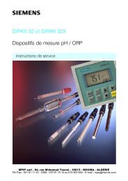
1.3 Operating principle<br />
The measured signal supplied by a resistance-based sensor (2, 3 or 4-wire connection) or by a thermocouple<br />
is amplified in the input stage. The voltage, which is proportional to the input quantity, is<br />
then converted to digital signals in an analog/digital converter ¡. Via electrical isolation ©, these signals<br />
are forwarded to the microprocessor. In the microprocessor ¢ they are converted in accordance<br />
with the sensor characteristic and further parameters (measuring range, attenuation and ambient temperature<br />
etc.).<br />
The signal prepared in this way is converted in a digital/analog converter £ to an impressed direct<br />
current of 4 to 20 mA. The auxiliary power source is located in the output signal circuit.<br />
24<br />
SITRANS TK/TK-H<br />
A5E00226012--01
Operating instructions<br />
7NG312*--1JN01, 7NG312*--2JN01<br />
Sensor<br />
TC<br />
RTD<br />
SITRANS TK-H<br />
¡<br />
© ¢ £<br />
I<br />
#<br />
#<br />
I<br />
Auxiliary power<br />
¤<br />
Load<br />
¥<br />
¦<br />
HART<br />
modem<br />
¡ Analog/digital converter<br />
© Electrical isolation<br />
¢ Microcontroller<br />
£ Digital/analog converter<br />
¤ Auxiliary power source<br />
¥ PC/Laptop<br />
¦ Interface (HART modem) for SIMA-<br />
TIC PDM<br />
Figure 1 Block diagram: operating principle of the SITRANS TK-H<br />
The transmitter is parameterised and operated with a PC ¥ that is connected to the two-wire line via<br />
the interface ¦. A hand-held communicator can also be used for this purpose. The signals needed for<br />
communication in conformity with the HART ® protocol V 5.7 are superimposed on the output current<br />
in accordance with the frequency shift keying (FSK) method.<br />
The data specific to the transmitter and the parameterisation data is stored in a non-volatile memory<br />
(EEPROM).<br />
1.4 Technical data<br />
Input<br />
Resistance thermometer<br />
Sensor type Pt25 to Pt1000 (DIN IEC 751)<br />
Pt25 to Pt1000 (JIS C 1604;<br />
α=0.00392 K -1 )<br />
Ni25 to Ni1000 (IEC 751)<br />
Cu25 to Cu1000<br />
Type of input connection Normal or averaging connection<br />
Normal connection<br />
1 resistance thermometer in 2, 3 or 4-wire connection<br />
Averaging connection Series or parallel connection of several 2-wire resistance thermometers<br />
for temperature or for adaption of other sensor types<br />
Connection<br />
Two-wire connection<br />
Line resistance parameterisable ≤60 Ω<br />
Three-wire connection No adjustment necessary<br />
Four-wire connection No adjustment necessary<br />
Sensor current<br />
≤0.2 mA<br />
Measuring range Parameterisable, see table, page 27<br />
Measuring span<br />
Minimum 10°C (18°F)<br />
Characteristic<br />
Temperature-linear<br />
Resistance-based sensor<br />
1 resistance-based sensor in 2, 3 or 4-wire connection<br />
SITRANS TK/TK-H<br />
A5E00226012--01 25
7NG312*--1JN01, 7NG312*--2JN01<br />
Operating instruction<br />
Connection<br />
Two-wire connection<br />
Line resistance parameterisable ≤60 Ω<br />
Three-wire connection No adjustment necessary<br />
Four-wire connection No adjustment necessary<br />
Sensor current<br />
≤0.2 mA<br />
Measuring range Parameterisable 0 to 390 Ω (Ohm Lo)<br />
0 to 2200 Ω (Ohm Hi)<br />
Measuring span Minimum 5 Ω (Ohm Lo)<br />
minimum 25 Ω (Ohm Hi)<br />
Characteristic<br />
Resistance linear or programmable (TK)<br />
Thermocouples<br />
Thermocouples Type L : Fe-CuNi DIN 43710<br />
Type J : Fe-CuNi DIN IEC 584<br />
Type K : NiCr-Ni DIN IEC 584<br />
Type E : NiCr-CuNi DIN IEC 584<br />
Type N : NiCrSi-NiSi BS4937 Part2<br />
Type T : Cu-CuNi DIN IEC 584<br />
Type U : Cu-CuNi DIN 43710<br />
Type S: Pt10Rh-Pt DIN IEC 584<br />
Type B: Pt30Rh-Pt6RhDIN IEC 584<br />
Type R: Pt13Rh-Pt DIN IEC 584<br />
Type C : W5-Re ASTM 988<br />
Type D : W3-Re ASTM 988<br />
Type of input connection Normal connection with 1 thermocouple<br />
Cold junction compensation Internal: with integrated resistance thermometer<br />
External: with external resistance thermometer<br />
External fixed: cold junction temperature adjustable as a fixed<br />
value<br />
Measuring range Parameterisable (see table, page 28)<br />
Measuring span Min. 50 to 100 °C (90 to 180 °F) (see table, page 28)<br />
Characteristic<br />
Temperature-linear<br />
mV sensor<br />
Measuring range --10 to 70 mV (Volt Lo)<br />
--100 to 1100 mV(Volt Hi)<br />
Minimum measuring span 2 mV (Volt Lo)<br />
20 mV (Volt Hi)<br />
Overload capac. of the input --0.5 to 35 V DC<br />
Characteristic<br />
Voltage-linear or programmed (TK)<br />
Input resistance<br />
≥1 MΩ<br />
Output<br />
Output signal<br />
Output range<br />
Failure signal (e.g. in the event<br />
of sensor breakage)<br />
Load of SITRANS TK<br />
Load of SITRANS TK-H<br />
Sampling cycle<br />
Attenuation<br />
Two-wire, 4 to 20 mA<br />
In the case of SITRANS TK-H, additionally with communication<br />
in conformity with HART 5.7<br />
3.5 to 23 mA<br />
3.5to23mA<br />
R L ≤(U H -6.5 V)/23 V [kΩ]<br />
R L ≤(U H -8 V)/23 V [kΩ]<br />
0.5 s nominal<br />
1.0 s in the case of Ohm Hi and Volt Hi<br />
Software filter of the 1st order<br />
0to30sinthecaseofSITRANSTK<br />
0to15sinthecaseofSITRANSTK-H<br />
26<br />
SITRANS TK/TK-H<br />
A5E00226012--01
Operating instructions<br />
7NG312*--1JN01, 7NG312*--2JN01<br />
Electrical isolation<br />
The input and output are electrically isolated<br />
Auxiliary power<br />
Maximum DC 35 V<br />
Test voltage<br />
U rms =3.75kV rms ,50Hz,1min<br />
Insulation<br />
500 V ac<br />
Auxiliary power in the case of DC6.5to35V(28VatEExiaversion)<br />
SITRANS TK<br />
Auxiliary power in the case of DC8to35V(28VatEExiaversion)<br />
SITRANS TK-H<br />
Ambient conditions<br />
Ambient temperature range --40 to +85 °C (--40 to +185 °F)<br />
Storage temperature range --40 to +85 °C (--40 to +185 °F)<br />
Relative humidity<br />
≤98 %, with condensation<br />
Measuring accuracy<br />
Reference conditions<br />
Auxiliary power 24 V 1 %<br />
Load<br />
500 Ω<br />
Ambient temperature 23 °C (73.4 °F)<br />
Warm up time<br />
>5 min<br />
Error of measurement<br />
Digital measuring error See table, page 27<br />
Analog output error<br />
7NG312*--1JN01, 7NG312*--2JN01<br />
Operating instruction<br />
Sensor types/accuracy<br />
Resistance thermometers<br />
Input<br />
Measuring<br />
range °C (°F)<br />
Pt25 to Pt500 -200 to 850<br />
(-328 to 1562)<br />
Pt501 to Pt1000 -200 to 350<br />
(-328 to 662)<br />
Ni25 toNi1000<br />
-50to250<br />
(-58 to 482)<br />
Cu25 to Cu1000<br />
-50to200<br />
(-58 to 392)<br />
Minimum<br />
Measuring span °C (°F)<br />
Digital<br />
Accuracy °C (°F)<br />
10 (18) 0.1<br />
(0.18)<br />
10 (18) 0.1<br />
(0.18)<br />
10 (18) 0.1<br />
(0.18)<br />
10 (18) 0.1<br />
(0.18)<br />
Resistance-based sensor<br />
Input<br />
Measuring<br />
range Ω<br />
Minimum<br />
Measuring span Ω<br />
Digital<br />
Accuracy Ω<br />
Resistance 0to390 5 0.05<br />
Resistance 0 to 2200 25 0.25<br />
Thermocouples<br />
Input<br />
Measuring<br />
range °C (°F)<br />
Minimum<br />
Measuring span °C (°F)<br />
Digital<br />
Accuracy °C (°F)<br />
Type B 500 to 1820 (932 to 3308) 50 (90) 2 (3.6)<br />
Type C (W5) 0 to 2300 (32 to 4172) 100 (180) 2 (3.6)<br />
Type D (W3) 0 to 2300 (32 to 4172) 100 (180) 2 (3.6)<br />
Type E -250 to 900 (-418 to 1652) 50 (90) 1 (1.8)<br />
Type J -210 to 1200 (-346 to 2192) 50 (90) 1 (1.8)<br />
Type K -230 to 1370 (-382 to 2498) 50 (90) 1 (1.8)<br />
Type L -200 to 900 (-328 to 1652) 50 (90) 1 (1.8)<br />
Type N -200 to 1300 (-328 to 2372) 50 (90) 1 (1.8)<br />
Type R 0 to 1750 (32 to 3182) 100 (180) 2 (3.6)<br />
Type S 0 to 1750 (32 to 3182) 100 (180) 2 (3.6)<br />
Type T -220 to 400 (-364 to 752) 40 (72) 1 (1.8)<br />
Type U -200 to 600 (-328 to 1112) 50 (90) 1 (1.8)<br />
Voltage sensor<br />
Input Measuring range mV Minimum<br />
Measuring span mV<br />
Digital<br />
Accuracy μV<br />
Millivolt sensor -10to70 2 40<br />
Millivolt sensor -100 to 1100 20 400<br />
The digital accuracy is the accuracy after A/D conversion including linearisation and conversion.<br />
The 4 to 20 mA output, an additional error amounting to
Operating instructions<br />
7NG312*--1JN01, 7NG312*--2JN01<br />
1.5 Ordering data<br />
Description<br />
SITRANS TK temperature transmitter<br />
for installation in the terminal housing Type B (DIN 43729),<br />
two-wire connection 4 to 20 mA, programmable, with electrical isolation<br />
Not explosion proof<br />
With intrinsically safe type of explosion protection Non incendive ”n”<br />
With intrinsically safe type of explosion protection ”i”<br />
SITRANS TK-H temperature transmitter<br />
for installation in the terminal housing Type B (DIN 43729),<br />
two-wire connection 4 to 20 mA, capable of communication according<br />
to HART ® V5.7, with electrical isolation<br />
Not explosion proof<br />
With intrinsically safe type of explosion protection Non incendive ”n”<br />
With intrinsically safe type of explosion protection ”i”<br />
Operating instructions SITRANS TK/TK-H<br />
language: German/English<br />
SIPROM TK parameterisation software for<br />
SITRANS TK; language: German/English<br />
Modem for SITRANS TK<br />
Interface (HART modem) for SIMATIC PDM<br />
Hand-held communicator<br />
With rechargeable batt. charger for AC 230 V and carrying bag,<br />
Type of protection: intrinsically safe EEx ia II C T4<br />
Language: German<br />
Language: English<br />
Order number<br />
7NG3120-1JN01<br />
7NG3121-1JN01<br />
7NG3122-1JN01<br />
7NG3120-2JN01<br />
7NG3121-2JN01<br />
7NG3122-2JN01<br />
A5E00226012<br />
7NG3190-8KB<br />
7NG3190-6KB<br />
7MF4997-1DA<br />
7MF4998-8KF<br />
7MF4998-8KT<br />
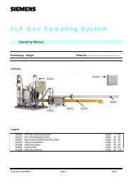
1.6 Dimensions<br />
44 mm (1.73 in)<br />
1 2<br />
3<br />
6<br />
4<br />
5<br />
33 mm (1.3 in)<br />
26.3 mm (1.04 in)<br />
Figure 2 Dimensions<br />
SITRANS TK/TK-H<br />
A5E00226012--01 29
7NG312*--1JN01, 7NG312*--2JN01<br />
Operating instruction<br />
2 Installation<br />
2.1 Installation in the terminal housing<br />
The SITRANS TK/TK-H transmitter must be installed in the housing. The housing’s type of protection and material<br />
must be adapted to the respective requirements.<br />
The environmental conditions specified in the technical data (Chapter 1.4, page 25) must be observed.<br />
Springs and screws for securing the transmitter are included in the delivery. The SITRANS TK/TK-H can be secured<br />
both in the base of the terminal housing and also in its raised cover.<br />
T r a ns m it t er<br />
Connection base<br />
Figure 3 Securing the SITRANS TK/TK-H transmitter in the cover of the terminal housing<br />
Transmitter<br />
Figure 4 Securing the SITRANS TK/TK-H transmitter in the base of the terminal housing<br />
! WARNING<br />
When the unit is installed in a hazardous area (zone 2), the<br />
housing must at least feature degree of protection IP 54 according<br />
to IEC 529.<br />
2.2 Electrical connection<br />
! WARNING<br />
The applicable national regulations must be observed during<br />
electrical installation, in explosion hazard areas particularly<br />
- the regulations governing electrical installations in explosion<br />
hazard rooms (Elex V),<br />
- the regulations for the erection of electrical installations in<br />
explosion hazard areas (VDE 0165) and<br />
- the conformity certification.<br />
Check whether the available auxiliary power agrees with the<br />
value stated on the rating plate.<br />
30<br />
SITRANS TK/TK-H<br />
A5E00226012--01
Operating instructions<br />
7NG312*--1JN01, 7NG312*--2JN01<br />
D For details of how to connect the sensor, see Figure 6, page 32 ”Sensor pin assignments”.<br />
D Auxiliary power<br />
Connect the wires of the auxiliary power supply to the ’’+’’ and ’’--’’ terminals, paying attention to the<br />
polarity (the unit is protected against polarity reversal).<br />
D Connecting cable<br />
Max. cable cross-section 2.5 mm 2 (0.003875 in 2 ).<br />
Lay signal cables separately from cables carrying voltages >60 V.<br />
Use cables with twisted wires.<br />
Avoid the proximity of large electrical installations or use shielded cables. The full specification accordingtoHART<br />
® , Version 5.7 can only be met when using shielded cables.<br />
! WARNING<br />
The HART modem must not be used in explosion hazard areas<br />
and must not be connected to intrinsically safe circuits.<br />
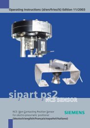
1 2<br />
+ --<br />
1, 2 U H ,I A<br />
3, 4, 5, 6 Sensor<br />
3<br />
6<br />
4<br />
5<br />
Figure 5 Terminal assignments<br />
SITRANS TK/TK-H<br />
A5E00226012--01 31
7NG312*--1JN01, 7NG312*--2JN01<br />
Operating instruction<br />
Resistance<br />
thermometers<br />
Thermocouple<br />
3<br />
6<br />
3<br />
6<br />
4<br />
5<br />
4<br />
5<br />
--<br />
RTD<br />
+<br />
T/C<br />
No line compensation 1) 6<br />
Internal cold junction compensation<br />
(CJC)<br />
3<br />
3<br />
6<br />
4<br />
5<br />
4<br />
5<br />
--<br />
RTD<br />
+<br />
RTD<br />
T/C<br />
Three-wire line compensation<br />
External CJC. No line compensation<br />
1)<br />
3<br />
6<br />
3<br />
6<br />
4<br />
5<br />
4<br />
5<br />
--<br />
RTD<br />
+<br />
RTD<br />
T/C<br />
Four-wire line compensation<br />
External CJC. Three-wire line<br />
compensation<br />
Note:<br />
Line resistance (per wire in the case of 3 / 4 -wire connections)<br />
T>600 °C (1112 °F):max.20Ω<br />
T
Operating instructions<br />
7NG312*--1JN01, 7NG312*--2JN01<br />
Potentiometer<br />
Resistance<br />
3<br />
4<br />
5<br />
R<br />
No compensation 2)<br />
6<br />
3<br />
6<br />
4<br />
5<br />
R<br />
No compensation 2)<br />
3<br />
6<br />
3<br />
6<br />
4<br />
5<br />
4<br />
5<br />
R<br />
R<br />
Three-wire compensation for<br />
transfer resistance 1)<br />
Three-wire line compensation<br />
3<br />
6<br />
3<br />
6<br />
4<br />
5<br />
4<br />
5<br />
R<br />
R<br />
Four-wire compensation for<br />
line and transfer resistance 1)<br />
Four-wire line compensation<br />
1) Resistance between start of resistance and sliding contact.<br />
2) Line resistance for compensation is programmable.<br />
Figure 6<br />
Sensor pin assignments (continued)<br />
Current measurement<br />
Voltage measurement<br />
3<br />
6<br />
3<br />
6<br />
4<br />
5<br />
4<br />
5<br />
R<br />
I<br />
+ --<br />
Figure 6<br />
Sensor pin assignments (continued)<br />
SITRANS TK/TK-H<br />
A5E00226012--01 33
7NG312*--1JN01, 7NG312*--2JN01<br />
Operating instruction<br />
+<br />
--<br />
Transmitter<br />
SITRANS TK-H<br />
+<br />
--<br />
230 Ω Auxiliary power<br />
HARTR<br />
modem<br />
PC/<br />
Laptop<br />
or<br />
RS-232-C<br />
Hand-held<br />
Communicator<br />
Figure 7 Connection to the hand-held communicator or a HART modem when using SITRANS TK-H<br />
34<br />
SITRANS TK/TK-H<br />
A5E00226012--01
Operating instructions<br />
7NG312*--1JN01, 7NG312*--2JN01<br />
3 Commissioning<br />
The transmitter’s parameters must be chosen to suit the requirements of the task in hand. Make sure that the parameters<br />
and the data on the rating plate correspond.<br />
Close the cover of the terminal housing after connecting the sensor and the auxiliary power supply. When the auxiliary<br />
power is activated, the transmitter assumes operation after a start up time of around 3 seconds.<br />
3.1 Functions<br />
When using SITRANS-TK, the following functions can be executed via the SIPROM TK parameterisation software,<br />
or, when using SITRANS TK-H, they can be executed via the SIMATIC PDM parameterisation software or the handheld<br />
communicator (for a description, see Chapter 4.2 Operation with the hand-held communicator)<br />
- Set the high output current limit<br />
- Store the measuring point identification data<br />
- Set the sensor type and the type of input connection<br />
- Set the measuring range, the unit and the attenuation<br />
- Set the output current in the event of a fault<br />
- Open-circuit monitoring<br />
- Current sensor function (SITRANS TK-H)<br />
- Sensor trimming (SITRANS TK-H)<br />
- Restore works calibration (SITRANS TK-H)<br />
- Measure line resistance<br />
3.2 Output current in the event of a fault<br />
The sensor lines and the electronic circuitry of the transmitter are constantly monitored. In the event of a fault, the<br />
output current is set to 3.6 or 23.0 mA. The respective value can be set.<br />
3.3 Open-circuit monitoring<br />
Open-circuit monitoring takes place during resistance measurement, resistance thermometer measurement and<br />
thermocouple measurement, but not voltage measurement.<br />
3.4 Current sensor function in the case of SITRANS TK-H<br />
Independently of the applied temperature, a parameterisable output current between 4 and 20 mA can<br />
be set to test the output circuit.<br />
3.5 Line compensation<br />
Line compensation is necessary for the following measurements:<br />
SITRANS TK/TK-H<br />
A5E00226012--01 35
7NG312*--1JN01, 7NG312*--2JN01<br />
Operating instruction<br />
- Two-wire resistance thermometers or resistance<br />
- Two-wire thermocouple with external Pt100 reference point<br />
Line compensation is set by numerically specifying the measured line resistance (sum of the foward<br />
and return conductors)<br />
36<br />
SITRANS TK/TK-H<br />
A5E00226012--01
Operating instructions<br />
7NG312*--1JN01, 7NG312*--2JN01<br />
4 Operation<br />
4.1 Operation with a PC/Laptop<br />
4.1.1 Operation with a PC/laptop when using SITRANS TK<br />
When using the SIPROM TK parameterisation software and the modem for SITRANS TK, the transmitter<br />
can be operated with a PC. To do this, simply connect the transmitter to the PC via the modem.<br />
In doing so, the power needed for the transmitter is supplied through the PC’s serial interface. For further<br />
details, please refer to the SIPROM TK instruction manual and, for details of the modem, refer to<br />
the SITRANS TK instruction manual.<br />
4.1.2 Operation with a PC/laptop when using SITRANS TK-H<br />
When using the SIMATIC PDM parameterisation software and the interface for the transmitter can be<br />
operated and parameterised with a PC. To do this, the interface must be connected to the output circuit.<br />
To this end, the transmitter’s power supply must be in operation and the load in the circuit must<br />
be at least 230 Ohm.<br />
4.2 Operation with a hand-held communicator<br />
Connect the hand-held communicator to the SITRANS TK-H (see Figure 7).<br />
Action keys<br />
With the key, you switch the hand-held communicator on and off. After switching on, the handheld<br />
communicator automatically assumes communication with the transmitter. The online menu<br />
appears in the display.<br />
With the key, you move the cursor up through the menu bar. The selected line of the menu is<br />
marked.<br />
With the key, you move the cursor down through the menu bar. The selected line of the menu is<br />
marked.<br />
With the key, you move the cursor to the right through the menu bar or you branch to a subroutine.<br />
The name of the selected subroutine is shown on the top edge of the display.<br />
With the key, you move the cursor to the left through the menu bar or you exit a subroutine.<br />
Function keys<br />
The function keys F1 to F4 are located under the LCD display. The functions of the keys, which differ<br />
from one menu to another, are shown on the bottom edge of the display.<br />
Alphanumeric and shift keys<br />
You can enter alphanumeric values by means of these keys. Whether a key functions as a number or<br />
letter key depends on the respective menu. Letters are selected by pressing the affiliated shift key beforehand.<br />
Please refer to the operation instructions of the HART communicator for all further information on operation<br />
and for the technical data.<br />
SITRANS TK/TK-H<br />
A5E00226012--01 37
7NG312*--1JN01, 7NG312*--2JN01<br />
Operating instruction<br />
5 Maintenance<br />
The transmitter requires no maintenance.<br />
38<br />
SITRANS TK/TK-H<br />
A5E00226012--01
Operating instructions<br />
7NG312*--1JN01, 7NG312*--2JN01<br />
6 Certificates<br />
6.1 EC Declaration of conformity<br />
SITRANS TK/TK-H<br />
A5E00226012--01 39
7NG312*--1JN01, 7NG312*--2JN01<br />
Operating instruction<br />
40<br />
SITRANS TK/TK-H<br />
A5E00226012--01
Operating instructions<br />
7NG312*--1JN01, 7NG312*--2JN01<br />
6.2 EC Type Examination Certificate<br />
SITRANS TK/TK-H<br />
A5E00226012--01 41
7NG312*--1JN01, 7NG312*--2JN01<br />
Operating instruction<br />
42<br />
SITRANS TK/TK-H<br />
A5E00226012--01
Operating instructions<br />
7NG312*--1JN01, 7NG312*--2JN01<br />
SITRANS TK/TK-H<br />
A5E00226012--01 43
7NG312*--1JN01, 7NG312*--2JN01<br />
Operating instruction<br />
44<br />
SITRANS TK/TK-H<br />
A5E00226012--01
Operating instructions<br />
7NG312*--1JN01, 7NG312*--2JN01<br />
SITRANS TK/TK-H<br />
A5E00226012--01 45
7NG312*--1JN01, 7NG312*--2JN01<br />
Operating instruction<br />
46<br />
SITRANS TK/TK-H<br />
A5E00226012--01
@1PA5E00226012@<br />
1P<br />
A5E00226012<br />
Siemens AG<br />
Bereich Automation and Drives<br />
Geschäftsgebiet Process Instrumentation and Analytics<br />
D-76181 Karlsruhe<br />
wwwsiemenscom/fielddevices<br />
A5E00226012-01
![[ ]](https://img.yumpu.com/53283450/1/184x260/-.jpg?quality=85)