R O B O T A C C E S S O R I E S
Schunk robot accessoires Part 1
Schunk robot accessoires Part 1
- No tags were found...

You also want an ePaper? Increase the reach of your titles
YUMPU automatically turns print PDFs into web optimized ePapers that Google loves.
R O B O T A C C E S S O R I E S<br />
A U T O M A T I O N
SCHUNK takes the initiative. For you.<br />
SCHUNK AUTOMATION anticipates trends in technology<br />
and customer needs and implements them in unique<br />
products, solutions and services.<br />
Profit from the synergy of our triple expertise as a<br />
pioneer in automation, in modular assembly automation<br />
and in modular robotics.<br />
With a complete range that includes gripper modules,<br />
turning and rotary units, linear modules, robot<br />
accessories, modular assembly automation and vision<br />
systems, we possess a compatible basis for delivering<br />
industry-specific solutions in every periphery.<br />
Discover SCHUNK, the partner that can strengthen your<br />
market position in your industry. Today – with the<br />
technological capacity of tomorrow.<br />
GrIPPING MODUleS rOTAry MODUleS lINeAr MODUleS rObOT ACCeSSOrIeS MODUlAr ASSeMbly MACHINe VISION<br />
AUTOMATION
Robot Accessories<br />
CONTENT<br />
Product Overview Page 4<br />
Synergies with SCHUNK Page 6<br />
Partners with a System Approach Page 8<br />
SCHUNK sets Standards Page 10<br />
Tool Changing Page 13<br />
Feed-through Page 201<br />
Protecting Page 243<br />
Compensation Page 309<br />
Measuring Page 399<br />
Machining Page 439<br />
Accessories Page 461<br />
Your Contact Partners at SCHUNK<br />
SCHUNK Service Page 493<br />
Subsidiaries/Distribution Partners Page 494<br />
Plants Page 496<br />
Fax Order/Catalog Order Page 497<br />
www.schunk.com<br />
3
Product Overview<br />
Robot Accessories
Product Overview<br />
Robot Accessories<br />
Tool Changing<br />
Miniature Change System<br />
MWS Page 14<br />
Quick Change System<br />
SWS-005 – 602 Page 22<br />
Options for SWS Page 108<br />
SWM-S / SWM-M Page 150<br />
Gripper Change System<br />
GWS 064 – 125 Page 160<br />
Manual Gripper Change System<br />
HWS-040 – 125 Page 176<br />
Flat Manual Change System<br />
FWS-050 Page 192<br />
Feed-through<br />
Feed-through for Robots<br />
DDF-031 – 160 Page 202<br />
Stationary Feed-through<br />
DDF-SE-080 – 120 Page 234<br />
Protecting<br />
Collision and Overload Protection<br />
OPS-080 – 200 Page 244<br />
OPS+063 – 101 Page 264<br />
OPR-061 – 221 Page 280<br />
Compensation<br />
Z Compensation Units<br />
AGE-Z-050 – 080 Page 310<br />
XY Compensation Units<br />
AGE-XY-050 – 080 Page 326<br />
F Compensation Units<br />
AGE-F-050 – 080 Page 342<br />
XYZ Compensation Units<br />
AGE-S-100 – 200 Page 362<br />
Insertion Units<br />
FUS-001 – 400 Page 382<br />
Measuring<br />
Force Sensors<br />
FTC-050 / FTCL-050 Page 400<br />
FT-Nano 17 – 43 Page 416<br />
FT-Mini 40 – 45 Page 422<br />
FT-Gamma Page 426<br />
FT-Delta Page 428<br />
FT-Theta Page 430<br />
FT-Omega 160 – 250 Page 432<br />
Machining<br />
Chanfering Spindle<br />
FDB-150 – 660 Page 440<br />
Accessories<br />
IN / MMS / SST / WV-G / SWV / DSV Page 462<br />
www.schunk.com<br />
5
Synergies with SCHUNK<br />
SCHUNK SYNERGY:<br />
Toolholding/Workholding and Automation<br />
Visions in two technology areas<br />
Toolholding/workholding and automation are our core competences. The resulting<br />
synergy effects make us unique. SCHUNK understands this complex world of<br />
clamping and handling like no one else. As a long-standing components specialist<br />
we know the demands and requirements of both technology areas. Moreover<br />
there’s the fascination of new possibilities. With our twofold expertise we can<br />
provide you with trend-setting leading technology. From the spindle to robotics.<br />
We call this “SCHUNK SYNERGY“. Get to know us as your active “all-in-one“<br />
partner – all the services from one source to benefit you.
Synergies with SCHUNK<br />
More innovative for you!<br />
SCHUNK opens up new horizons<br />
Shaping technology. Putting the dynamics into processes. Increasing added<br />
value. SCHUNK is one of the world’s leading manufacturers for clamping and<br />
gripping technology, and our name is synonymous with innovation.<br />
We are a family-run business based in Lauffen, Germany and a globally active<br />
company rolled into one. Continual dialog with our customers and the personal<br />
responsibility and individual endeavors of each andevery employee to perform<br />
the work faultlessly and in the best quality produce solutions, which precisely<br />
conform to our customers’ needs and the demanding requirements of the<br />
market.<br />
SCHUNK opens up new horizons. For even today, we are focusing on the<br />
opportunities of tomorrow, and boast a comprehensive range of future-oriented<br />
technologies. Our promise: High-quality solutions that not only live up to your<br />
expectations, but exceed them! And on this premise, we have consistently based<br />
our corporate philosophy: Quality, reliability and pioneering spirit.<br />
Through continuous development, we are constantly<br />
opening up new prospects for our customers.<br />
Technical creativity, supreme expertise and soundly<br />
based experience are the success factors we offer<br />
you in engineering, production and service.<br />
We are thinking ahead – for you!<br />
www.schunk.com<br />
7
Partners with a System Approach<br />
System partners<br />
Solutions from one source<br />
As one of the most innovative market leaders, we offer unique solutions with<br />
our gripping systems, rotary units, linear modules, robot accessories and<br />
customized applications. Our broad product range enables us to offer precisely<br />
the right solution, even for your specialized tasks. We are development partners<br />
for various industries and specialize in your handling applications.<br />
Whenever handling tasks require maximum precision and economic efficiency,<br />
SCHUNK provides the momentum and the perfect solution for putting them into<br />
practice.<br />
You, too, can benefit from our complete automation range from one source.<br />
From standardized and individual gripper modules to complex functional modules.<br />
Rediscover SCHUNK! Again and again.
Partners with a System Approach<br />
Automation product range<br />
Gripping Modules<br />
SCHUNK currently has the most comprehensive range of universal grippers and<br />
gripper modules for small components. Pneumatic or electric. Offering all<br />
features from state-of-the-art materials and coatings employed as standard to<br />
internal media feed-through. With our high level of technical expertise,<br />
SCHUNK sets the trend for cost-efficient handling in any industry, in any field.<br />
Rotary Modules<br />
Technology and functionality in the most compact form. SCHUNK’s range of<br />
rotary modules represents the entire spectrum of compact turning and rotary<br />
units, swivel heads and rotary fingers. In other words, it’s the ideal solution for<br />
handling tasks.<br />
Linear Modules<br />
Precision mini-slides, pneumatic linear modules, rigid gantry axes and axes with<br />
servo-electric linear drive – the SCHUNK product range offers linear technology<br />
for high-speed automated assembly. Compact and designed as a modular<br />
system.<br />
Robot Accessories<br />
Robot accessories from SCHUNK – the complete range of modules for perfect<br />
interplay between the robot arm and the tool. Suitable for all types of robot, it<br />
is also an ideal enhancement to flexible robot applications.<br />
Machine Vision<br />
In automated assembly, image processing modules from SCHUNK represent the<br />
flexible solution for manifold sensor applications. All high-quality components<br />
are perfectly phased to each other. The necessary software for object and<br />
posi tion detection stands for 100 % process reliability.<br />
Modular Assembly Automation<br />
Flexible – fast – future-secure. This is the system GEMOTEC from SCHUNK.<br />
The comprehensive program of pneumatic and electric modules opens an unforeseen<br />
variety of combination possibilities. All actuators are compatible with each<br />
other. Where other companies still have to conduct design work, the system<br />
GEMOTEC is already assembled. Fast and straightforward.<br />
www.schunk.com<br />
9
SCHUNK sets Standards<br />
Robot Accessories<br />
The SCHUNK product range for reliable combinations<br />
SCHUNK robot accessories comprise a comprehensive range of modules for<br />
mechanical, sensoric and energetic combination of handling devices and robots.<br />
Quick-change systems, rotary feed-throughs, collision<br />
and overload protection, force sensors, compensation<br />
units and insertion units ensure the perfect interplay<br />
between the robot arm and the gripper. The basis of this leading-edge<br />
technology “made in Germany” is our ongoing innovative<br />
excellence.<br />
SCHUNK offers more. More willingness to accept challenges<br />
and put ideas into practice, more commitment to investment in innovative technology,<br />
more flexibility in solving the problems presented by a rapidly developing<br />
future. That’s what we stand for!<br />
For the benefit of our customers.<br />
Good reasons for choosing robot accessories from SCHUNK:<br />
Comprehensive range from a single source<br />
Suitable for almost all types of robot<br />
Easy integration<br />
Compact designs<br />
Series with well-matched sizes
SCHUNK sets Standards<br />
Product highlight – SWS Quick-change System<br />
The shortest possible changeover times, safety included<br />
Facts which speak for themselves:<br />
Wherever short changeover times between a handling device and a robot tool is<br />
required, the SWS quick-change system is the ideal choice. The patented highlight<br />
is the pneumatically operated locking mechanism for force-free locking and<br />
unlocking as well as for self maintained locking in locked position. Using adapters,<br />
SWS is universal and increases the flexibility of the robot in all automated<br />
production lines.<br />
Complete series with 11 sizes<br />
Compact dimensions as drive is incorporated into the housing<br />
High bearing load capacity<br />
Option for universal energy transmission for fluid media with self-sealing<br />
couplings<br />
Optional adapter coding via plug connector<br />
www.schunk.com<br />
11
Tool Changing
Tool Changing<br />
TOOL CHANGING<br />
Series Size Page<br />
Miniature Change System<br />
MWS 14<br />
MWS 020 18<br />
Quick-change System<br />
SWS-I 22<br />
SWS-I 011 26<br />
SWS 30<br />
SWS 005 36<br />
SWS 011 40<br />
SWS 020 44<br />
SWS 021 50<br />
SWS 040 56<br />
SWS 041 62<br />
SWS 060 68<br />
SWS 071 74<br />
SWS 110 80<br />
SWS 150 84<br />
SWS 300 90<br />
SWS-L 210 96<br />
SWS-L 310 100<br />
SWS-L 510 104<br />
SWS-L Options 108<br />
SWS-L 602 110<br />
SWS Options 112<br />
A15 for SWS 114<br />
B15 for SWS 116<br />
E2A for SWS 118<br />
E3A for SWS 120<br />
E10-005 for SWS 122<br />
E10-010 for SWS 124<br />
E20 for SWS 126<br />
G19 for SWS 128<br />
G26 for SWS 130<br />
K19 for SWS 132<br />
K26 for SWS 134<br />
MT8 for SWS 136<br />
MT14 for SWS 138<br />
R19 for SWS 140<br />
R26 for SWS 144<br />
R32 for SWS 148<br />
SWM for SWS 150<br />
SWM-S for SWS 152<br />
SWM-M for SWS 158<br />
Series Size Page<br />
Gripper Change System<br />
GWS 160<br />
GWS 064 164<br />
GWS 080 168<br />
GWS 125 172<br />
Manual Gripper Change System<br />
HWS 176<br />
HWS 040 180<br />
HWS 050 182<br />
HWS 063 184<br />
HWS 080 186<br />
HWS 100 188<br />
HWS 125 190<br />
Flat Manual Gripper Change System<br />
FWS 192<br />
FWS 050 196<br />
www.schunk.com<br />
13
MWS<br />
Tool Changing · Miniature Change System<br />
Sizes<br />
020<br />
Handling weight<br />
0.5 kg<br />
Moment load M x<br />
0.5 Nm<br />
Moment load M y<br />
0.5 Nm<br />
Moment load M z<br />
0.2 Nm<br />
Application example<br />
Automated assembly of writing utensils:<br />
Lead refills are inserted into mechanical<br />
pencils. The MWS ensures fast changing<br />
of the gripping modules and tools.<br />
MWS 20 Miniature Quick-change<br />
System<br />
ELM 23-H70 Linear Module with<br />
direct drive (GEMOTECH System)<br />
ELM 37-H260 Linear Module with<br />
direct drive (GEMOTECH System)<br />
EPM 48-0300 Gantry Module with<br />
direct drive (GEMOTECH System)<br />
14 www.schunk.com
MWS<br />
Tool Changing · Miniature Change System<br />
Miniature Change Systems<br />
Manual tool changing system for small manipulators and grippers,<br />
with integrated air and electric feed-through<br />
Area of application<br />
Ideal for use in microsystems technology, especially for handling<br />
of miniature components<br />
Your advantages and benefits<br />
Extremely flat design<br />
for low interfering contours<br />
Easy handling without the need of additional tools<br />
Can be released easily and quickly<br />
Free center bore<br />
for feed-through of parts, camera, laser beams, etc.<br />
Integrated feed-throughs<br />
for 6 fluid or electric media/signals<br />
Suitable storage rack<br />
for reliable positioning of your tools available as accessory<br />
ISO flange pattern<br />
for easy installation, conforms to DIN 32565 Level 4<br />
General information on the series<br />
Working principle<br />
locking is achieved by turning the actuating ring<br />
Actuation<br />
manual via integrated locking ring<br />
Energy transmission<br />
integrated pneumatic/fluid and electric feed-through<br />
Warranty<br />
24 months<br />
www.schunk.com<br />
15
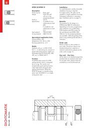
MWS<br />
Tool Changing · Miniature Change System<br />
Sectional diagram<br />
End plate<br />
Locking ring<br />
self-locking and sturdy<br />
Torque pin<br />
for exact coupling and maximum precision<br />
Locking mechanism<br />
self-locking and sturdy<br />
Pneumatic feed-through<br />
no interfering contour due to integration<br />
in housing<br />
Electric feed-through<br />
for electric energy and signal transmission<br />
Functional characteristics<br />
The miniature change system (MWS) consists of a miniature change head (MWK)<br />
and a miniature change adapter (MWA).<br />
The miniature change head (MWK) is connected with the miniature change adapter<br />
(MWA) by a form-fit connection by actuating the locking ring.<br />
Integrated pneumatic feed-throughs supply the tool reliably with energy.<br />
16 www.schunk.com
MWS<br />
Tool Changing · Miniature Change System<br />
Accessories<br />
Accessories from SCHUNK –<br />
the suitable supplement for<br />
maximum functionality,<br />
reliability and performance<br />
of all automation modules.<br />
i The specific size of the desired accessories, availability for the model and the name and ID no. can be found in the additional diagrams following each model.<br />
General notes on the series<br />
Utilization under extreme ambient conditions<br />
Please be aware that use under extreme conditions (e.g. with coolants, or in<br />
the pre sence of casting dust or abrasive dust) can significantly reduce the tool life of<br />
these units, for which we can make no guarantee. In many cases, however, we have a<br />
solution. Please contact us.<br />
www.schunk.com<br />
17
MWS 020<br />
Tool Changing · Miniature Change System<br />
Moment load<br />
M x<br />
M y<br />
M z<br />
max. 0.5 Nm<br />
max. 0.5 Nm<br />
max. 0.2 Nm<br />
Technical data<br />
Designation MWK 020 MWA 020<br />
ID 0305623 0305624<br />
Maximum payload [kg] 0.5<br />
Required locking force/unlocking force [N] 7 ... 13<br />
Required locking moment [Nm] 0.1 ... 0.2<br />
Repeat accuracy [mm] 0.1<br />
Total weight [kg] 16<br />
Weight of head [g] 7<br />
Weight of adapter [g] 9<br />
Pneumatic energy transmission (direct connection) 2x (can be expanded up to 6x, if there is no electric energy transmission)<br />
Electric energy transmission 4x (can be expanded up to 6x, if there is no pneumatic energy transmission)<br />
Max. permissible XY axis misalignment during coupling (calculated) [mm] ± 0.3<br />
Max. permissible angular misalignment on Z during coupling (calculated) [°] ± 0.8<br />
Max. distance during locking in Z [mm] 0.25<br />
Max. static moment M X and M Y [Nm] 0.5<br />
Max. static moment M Z [Nm] 0.2<br />
Max. tensile force load in Z [N] 50<br />
Spring-mounted electric contacts<br />
U=24 VDC, Imax=1 A<br />
Diameter of center bore [mm] 7.5<br />
18 www.schunk.com
MWS 020<br />
Tool Changing · Miniature Change System<br />
Main views<br />
The drawing shows the basic version of the quick-change system without<br />
dimensional consideration of the options described below.<br />
Connection, robot-side<br />
Connection, tool-side<br />
Bolt pitch circle<br />
Through-bore<br />
Unlocked position<br />
Locked position<br />
www.schunk.com<br />
19
MWS 020<br />
Tool Changing · Miniature Change System<br />
Function of fluid and electric feed-through<br />
Position of fluid and electric feed-through<br />
Fluid feed-through<br />
Electric signal feed-through<br />
Electric power feed-through<br />
Fluid feed-through<br />
Electric signal feed-through<br />
Electric power feed-through<br />
Electric option for MWS 20<br />
Designation<br />
ID<br />
MWK-E4 305693 Electric contact 4 x 24 VDE/1 A for MWK<br />
MWA-E4 305694 Electric contact 4 x 24 VDE/1 A for MWA<br />
20 www.schunk.com
MWS 020<br />
Tool Changing · Miniature Change System<br />
www.schunk.com<br />
21
SWS-I<br />
Tool Changing · Quick-change System · With integrated Valves<br />
Size<br />
011<br />
Handling weight<br />
16 kg<br />
Moment load M x<br />
25 Nm<br />
Moment load M y<br />
25 Nm<br />
Moment load M z<br />
34 Nm<br />
Application example<br />
6-axis buckling-arm robot for changing the<br />
gripper tools from the storage rack SWM-S.<br />
The storage rack contains applicationspecific<br />
tools with collision- and overload<br />
protection (OPR), compensation units (AGE)<br />
or insertion units (FUS).<br />
Quick-change Head SWK-I-011<br />
Quick-change Adapter SWA-I-011<br />
Application-specific<br />
Gripper tools<br />
22 www.schunk.com
SWS-I<br />
Tool Changing · Quick-change System · With integrated Valves<br />
Quick-change System<br />
pneumatic tool change system with integrated 3/2<br />
directional valves and patented locking system<br />
Area of application<br />
Can be used wherever short changeover times between a handling<br />
device and a tool are required<br />
Your advantages and benefits<br />
Integrated 3/2 directional control valve<br />
for easy hose connection and assembly<br />
Patented self-retaining system<br />
for a safe connection between gripper-change head and<br />
gripper-change adapter<br />
Drive incorporated into the housing<br />
for compact dimensions and fewer interfering contours.<br />
All functional components are made from hardened steel<br />
for a greater change system load bearing capacity<br />
Integrated electric feed-through<br />
for safe monitoring of tools<br />
Integrated air feed-through<br />
for safe energy supply to the handling modules and tools<br />
Storage racks to fit all sizes<br />
available as an accessory for reliable positioning of your tools<br />
ISO flange<br />
for easy attachment to most types of robots without additional<br />
adapter plates<br />
General information on the series<br />
Working principle<br />
Piston-activated locking bearings<br />
Material<br />
Housing made from high-strength, hard-coated aluminum, functional components<br />
made from hardened steel<br />
Actuation<br />
Pneumatic, with filtered compressed air (10 µm): dry or lubricated<br />
Operating pressure range<br />
From 4.5 bar to 6 bar<br />
Maintenance<br />
Prelubricated – relubrication recommended after 2 million cycles<br />
Ambient temperature<br />
From 5 °C to 60 °C<br />
Energy transmission<br />
Variable via attachment modules, depending on the type<br />
Self-locking<br />
Mechanical when locking<br />
Warranty<br />
24 months<br />
www.schunk.com<br />
23
SWS-I<br />
Tool Changing · Quick-change System · With integrated Valves<br />
Sectional diagram<br />
Locking mechanism<br />
trouble-free locking and unlocking,<br />
self-locking in locked position<br />
Drive<br />
pneumatic and powerful with extremely<br />
easy handling<br />
Pneumatics freed-through<br />
incorporation into the housing therefore no<br />
interfering contours<br />
Integrated 3/2 directional valves<br />
for control of the change system<br />
and the tool<br />
Electrical feed-throughs<br />
incorporation into the housing therefore no<br />
interfering contours<br />
Function description<br />
The quick-change system SWS-I consists of a robot-side change-head and a<br />
tool-side change-adapter. The adapter is self-locking in the head via a patented<br />
ball mechanism and it is supplied with compressed air by the integrated valves.<br />
Two of the six 3/2 pneumatic valves are required for locking and unlocking of the<br />
adapter; the other four are available for other tasks.<br />
The electric supply of the tools takes place via a contact plate with six free<br />
contacts, which supply, for example up to four proximity switches with electricity or<br />
can return their signals to the control system.<br />
24 www.schunk.com
SWS-I<br />
Tool Changing · Quick-change System · With integrated Valves<br />
Accessories<br />
Storage racks<br />
Accessories from SCHUNK –<br />
the suitable complement for<br />
the highest level of functionality,<br />
reliability and consistent<br />
performance of all<br />
automaton modules.<br />
Cable connectors<br />
i For the exact size of the accessories, the availability for this size and the designation and ID, please refer to the additional views at the end of the size in question.<br />
General information on the series<br />
Use under extreme ambient conditions<br />
Please note that the use in extreme ambient conditions (e.g. in the coolant zone, in<br />
the presence of abrasive dust) can significantly reduce the life span of these units<br />
and we cannot accept any liability for this reduction.<br />
However, in many cases we have a solution at hand. Please ask for details.<br />
www.schunk.com<br />
25
SWS-I-011<br />
Tool Changing · Quick-change System · With integrated Valves<br />
Product description<br />
Small, light-weighted and compact with six<br />
pieces integrated 3/2 directional valves.<br />
No-Touch-Locking<br />
Locking without touching. Ensures that the SWS is<br />
securely locked even when the SWK and SWA do not<br />
touch. A maximum distance of 3 mm is possible.<br />
Patented, self-retaining locking system<br />
Air feed-through with specially developed<br />
rubber seals<br />
Moment load<br />
M x<br />
M y<br />
M z<br />
max. 25.0 Nm<br />
max. 25.0 Nm<br />
max. 34.0 Nm<br />
i The dynamic moment load can be up to three<br />
times longer than the static moment load. Tests<br />
have shown that the system will only begin to<br />
fail in the event of 12-fold static moment.<br />
Technical data<br />
Designation SWK-I-011-4-6-R SWK-I-011-4-6-A SWA-I-011-4-6<br />
ID 0302811 0302812 0302810<br />
Head Head Adapter<br />
Cable and air outlet radial axial<br />
Maximum payload [kg] 16 16 16 At low moments a higher payload is possible<br />
Locking force (from 6 bar) [N] 1068 1068 1068 At higher tensile forces the system “falls” into the<br />
self-retaining status<br />
Repeatability [mm] 0.01 0.01 0.01 Tested at 1 million cycles<br />
Weight [kg] 0.59 0.59 0.59 Head-side 0.495 kg; adapter side 0.095 kg<br />
Maximum distance on locking [mm] 3.0 3.0 3.0 No-Touch-Locking technology allows the parts to be coupled<br />
without the head and adapter touching<br />
Energy transmission pneumatic<br />
4 x pneumatic M5 max. 7 bar<br />
Energy transmission electrical 6x 3A/50V 6x 3A/50V 6x 3A/50V<br />
Maximum permissible XY offset [mm] ± 1 ± 1 ± 1 Maximum permissible XY offset when locking<br />
Maximum permissible angular offset [°] ± 2 ± 2 ± 2 Maximum permissible angular offset around the Z axis when locking<br />
26 www.schunk.com
Main views SWK-I-011-4-6-R and SWA-I-011-4-6<br />
SWS-I-011<br />
Tool Changing · Quick-change System · With integrated Valves<br />
Connection unit<br />
Connection assembly<br />
Bolt pitch circle<br />
Energy transmission<br />
Main connection for compressed air<br />
Change in dimensions SWK-I-011-4-6-A<br />
SWA-I-011 with pluggable electrical option<br />
Connection unit<br />
Connection assembly<br />
Bolt pitch circle<br />
Energy transmission<br />
Main connection for compressed air<br />
Designation<br />
ID<br />
SWA-I-011-4-6-S 0302809<br />
Cable connector enclosed.<br />
w w w . s c h u n k . c o m<br />
27
SWS-I-011<br />
Tool Changing · Quick-change System · With integrated Valves<br />
Distribution flange (axial on radial)<br />
Distribution flange without workpiece stops<br />
SWA with distribution flange and rack bolt<br />
The distribution flange is mounted on the SWA and allows radial grip of<br />
air at the SWA.<br />
Optionally, 3 bolts can be mounted on the SWM for storage purposes.<br />
Air feed-through<br />
Designation<br />
ID<br />
A-SWA-I-011-V 0302813<br />
Distribution flange with workpiece stops<br />
Cable connector<br />
Air feed-through<br />
Designation ID Scope of delivery<br />
Distribution flange<br />
A-SWA-I-011-V 0302813 1x<br />
Workpiece stops<br />
SWMTSS-M5-3303 0302577 3x<br />
Designation<br />
ID<br />
for SWK-I-011-4-6-R (ID 0302811)<br />
KAS-SWK-I-011-90 9949866<br />
for SWK-I-011-4-6-R (ID 0302811)<br />
KAS-D15-SWK-I-0 0301282<br />
28 www.schunk.com
SWS-I-011<br />
Tool Changing · Quick-change System · With integrated Valves<br />
Standard adpater plates for ISO flanges<br />
Robot-side connection<br />
Tool-side connection<br />
Adapter plate A31.5<br />
For mounting the SWK-011 directly to the flange in accordance with ISO 9409-1-<br />
A31.5<br />
Designation<br />
ID<br />
A-SWK-011-ISO-A-31.5 0302221<br />
Robot-side connection<br />
Tool-side connection<br />
Adapter plate A40<br />
For mounting the SWK-011 directly to the flange in accordance with ISO 9409-1-A40<br />
Designation<br />
ID<br />
A-SWK-011-ISO-A-40 0302222<br />
Design note for adapter plates<br />
Robot-side connection<br />
Tool-side connection<br />
Adapter plate A50<br />
For mounting the SWK-011 directly to the flange in accordance with ISO 9409-1-A50<br />
Tool-side connection<br />
Recommendation for designing the adaptation. Adapters are required for sealing<br />
the piston area.<br />
Designation<br />
ID<br />
A-SWK-011-ISO-A-50 0302223<br />
www.schunk.com<br />
29
SWS<br />
Tool Changing · Quick-change System<br />
Sizes<br />
005 .. 602<br />
Handling weight<br />
up to 1000 kg<br />
Moment load M x<br />
up to 13000 Nm<br />
Moment load M y<br />
up to 13000 Nm<br />
Moment load M z<br />
up to 5500 Nm<br />
Application example<br />
Joining tool for attaching small to mediumsized<br />
workpieces. The tool can be used<br />
in both clean and dirty environments.<br />
The quick-change system means that it<br />
can be used alternately with other tools<br />
on the robot flange.<br />
DPZ-plus 100 3-Finger Centric<br />
Gripper<br />
FUS-213C Insertion Unit<br />
SWS-041 Quick-change System<br />
30 www.schunk.com
SWS<br />
Tool Changing · Quick-change System<br />
Quick-change System<br />
Pneumatic tool changing system<br />
with patented locking system<br />
Area of application<br />
Can be used wherever short changeover times between a handling<br />
device and a tool (gripper, electrode holder) are required<br />
Your advantages and benefits<br />
Complete series with 15 sizes<br />
for an optimum selection of sizes and a wide range of applications<br />
Patented self-retaining locking system<br />
for a safe connection between the quick-change head and the<br />
quick-change adapter<br />
Drive incorporated into the housing<br />
for compact dimensions and fewer interfering contours<br />
All functional components made from hardened steel<br />
for a greater change system load bearing capacity<br />
Wide range of cable connectors<br />
for universal energy transmission options<br />
Integrated air feed-through<br />
for safe energy supply to the handling modules and tools<br />
Transmission options for other media<br />
with optional self-sealing couplings<br />
Adapter coding<br />
possible via plug connection<br />
Storage racks to fit all sizes<br />
available as an accessory for reliable positioning of your tools<br />
ISO flange<br />
for easy attachment to most types of robots without additional<br />
adapter plates<br />
General information on the series<br />
Working principle<br />
Piston-activated locking bearings<br />
Material<br />
Housing made from high-strength, hard-coated aluminum, functional components<br />
made from hardened steel<br />
Actuation<br />
Pneumatic, with filtered compressed air (10 µm): dry or lubricated<br />
Operating pressure range<br />
From 4.5 bar to 6 bar<br />
Maintenance<br />
Prelubricated – relubrication recommended after 2 million cycles<br />
Ambient temperature<br />
From 5 °C to 60 °C<br />
Energy transmission<br />
Variable via attachment modules, depending on the type<br />
Monitoring for the locking mechanism<br />
via inductive proximity switches, depending on the size<br />
Self-locking<br />
Mechanical when locking<br />
Warranty<br />
24 months<br />
www.schunk.com<br />
31
SWS<br />
Tool Changing · Quick-change System<br />
Sectional diagram<br />
Sensor monitoring for the locking<br />
mechanism<br />
incorporated into the housing in the SWS-<br />
110, optional with other sizes<br />
Housing<br />
weight-reduced through the use of a highstrength<br />
aluminum alloy<br />
Drive<br />
pneumatic and powerful with extremely easy<br />
handling<br />
Locking mechanism<br />
trouble-free locking and unlocking, self-locking<br />
in locked position<br />
Pneumatics feed-through<br />
incorporation into the housing therefore no<br />
interfering contours, also suitable for vacuums<br />
Function description<br />
Automatic changing of the robot tool (e.g. gripper, vacuum lifting devices, pneumatically<br />
or electrically driven tools, electrode holders etc.) increases the flexibility of your robot.<br />
The quick-change system (SWS) consists of a quick-change head (SWK) and<br />
a quick-change adapter (SWA). The SWK, mounted onto the robot, couples up the<br />
SWA mounted onto your tool. A pneumatically driven locking piston, with its<br />
patented design, ensures that the connection is secure. After coupling, pneumatic<br />
and electric feed-throughs automatically supply your robot tool.<br />
32 www.schunk.com
SWS<br />
Tool Changing · Quick-change System<br />
Accessories<br />
SIP sensor interface plate<br />
Storage racks<br />
Accessories from SCHUNK –<br />
the suitable supplement for<br />
maximum functionality, reliability<br />
and performance of<br />
all automation modules.<br />
Cable connectors<br />
Electronic modules<br />
i For the exact size of the accessories, the availability for this size and the designation and ID, please refer to the additional views at the end of the size in question.<br />
General information on the series<br />
Use in extreme ambient conditions<br />
Please note that use in extreme ambient conditions (e.g. in the coolant zone, in<br />
the presence of abrasive dust) can significantly reduce the life span of these units<br />
and we cannot accept any liability for this reduction. However, in many cases we<br />
have a solution at hand. Please ask for details.<br />
www.schunk.com<br />
33
SWS<br />
Tool Changing · Quick-change System<br />
Detailed function description<br />
SWK - SWA before locking<br />
Piston<br />
Locking piston<br />
No-Touch-Locking <br />
(no robot pressure force<br />
needed when locking)<br />
Hardened steel insert<br />
Hardened locking ball<br />
on the first locking bevel<br />
Detailed view<br />
When the piston is actuated the locking balls are<br />
pushed under the hardened steel ring and the<br />
adapter is pulled onto the head.<br />
Locking ball on the second<br />
locking piston bevel<br />
SWK - SWA when locked<br />
First locking bevel<br />
Detailed view<br />
In the event of a drop in air pressure, the locking piston<br />
is held by the cylindrical part of the locking piston.<br />
The piston seal friction prevents the piston from moving<br />
due to its own weight or because of vibrations.<br />
The head and the adapter can only be separated by<br />
pneumatic actuation of the piston.<br />
SWK - SWA in self-locking position<br />
Locking ball on the cylindrical part of the locking<br />
piston. Compressed air is needed to detach it.<br />
Detailed view<br />
34 www.schunk.com
SWS<br />
Tool Changing · Quick-change System<br />
Selecting the quick-change system<br />
1. Size selection<br />
a. Simple size determination<br />
If the change system is subject to very low forces and moments you can select the quick-change head on the basis of the maximum payload.<br />
Choose a quick-change system which has a maximum payload larger than the useful load of your robot.<br />
Choose the accurate method if the change system is subject to higher moments.<br />
b. The accurate method<br />
Selecting the correct quick-change system depends on the moment load which the system is subject to.<br />
Proceed as follows to calculate the maximum moments.<br />
· Determine the center of gravity and the weight (m in Newtons) of your heaviest tool (gripper, adapter plate and tool)<br />
· Determine the distance (D in meters) from the center of gravity to the underside of the quick-change adapter (SWA)<br />
· Calculate the static moment (m x D)<br />
· Select a quick-change system with a permissible moment that is equal to or greater than the moment you have calculated<br />
Robot movements can also have an effect on the change system. Dynamic moments can come into effect which are 2 – 3 times greater than the static moments<br />
you have calculated. The SWS quick-change systems are designed for handling dynamic moments which can be up to three times greater than the static moments.<br />
2. Pneumatics and electrics<br />
Determine the number and sizes of the pneumatic and electric feed-throughs.<br />
3. Temperature and chemicals<br />
Nitrile seals on the quick-change units ensure optimum air feed-through. Buna N O-rings seal the piston chamber very effectively.<br />
Both materials are resistant to many chemicals and are suited to temperatures between 5 °C and 60 °C.<br />
SWS sizes at a glance<br />
Designation SWS-005 SWS-011 SWS-020 SWS-021 SWS-040 SWS-041<br />
Recommended handling weight [kg] 8 16 25 25 50 50<br />
Locking force at 5.5 bar [N] 690 1068 2314 2314 4540 4540<br />
Static moment M x and M y [Nm] 12.5 25 56.5 56.5 157 157<br />
Static moment M z [Nm] 17 34 78 78 216 216<br />
Pneumatic feed-through 6x M5 6x M5 12x M5 8x G 1/8” 8x G 1/8” 6x G 3/8”<br />
Air connections, locked and unlocked M5 M5 M5 M5 G 1/8” G 1/8”<br />
Designation SWS-060 SWS-071 SWS-110 SWS-150 SWS-300<br />
Recommended handling weight [kg] 75 79 150 200 455<br />
Locking force at 5.5 bar [N] 7387 8075 12149 16109 35333<br />
Static moment M x and M y [Nm] 197 395 784 1356 3870<br />
Static moment M z [Nm] 294 395 784 1130 2825<br />
Pneumatic feed-through 8x G 1/8” 8x G 1/4” 8x G 3/8” 10x G 3/8” 10x G 3/8”<br />
Air connections, locked and unlocked G 1/8” G 1/8” G 1/8” G 1/8” G 1/4”<br />
www.schunk.com<br />
35
SWS-005<br />
Tool Changing · Quick-change System · Light Load<br />
Product description<br />
Ejector function on the SWK<br />
Prevents the head and the adapter from sticking<br />
together after unlocking.<br />
A common problem when working with light tools.<br />
High degree of repeat accuracy<br />
No-Touch-Locking<br />
Locking without touching. Ensures that the SWS is<br />
securely locked even when the SWK and SWA do not<br />
touch. A maximum distance of 3 mm is possible.<br />
Patented, self-retaining locking system<br />
Air feed-through with specially developed<br />
rubber seals<br />
Moment load<br />
M x<br />
M y<br />
M z<br />
max. 12.5 Nm<br />
max. 12.5 Nm<br />
max. 17.0 Nm<br />
i The dynamic moment load can be up to three times<br />
larger than the static moment load. Tests have<br />
shown that the system will only begin to fail in the<br />
event of 12-fold static moment.<br />
Technical data<br />
Designation<br />
SWS-005<br />
Maximum payload [kg] 8 A larger payload is possible with smaller moments<br />
Static moment load M xy [Nm] 12.5<br />
Static moment load M z [Nm] 17<br />
Dynamic moment load M xy [Nm] 37.5<br />
Dynamic moment load M z [Nm] 51<br />
Locking force (at 6 bar) [N] 710 In the event of higher tensile forces the system “falls” into the self-locking position<br />
Repeat accuracy [mm] 0.01 Tested at 1 million cycles<br />
Weight [kg] 0.37 0.27 kg head; 0.1 kg adapter<br />
Min./max. distance on locking [mm] 1.5 / 3.0 No-Touch-Locking technology allows the parts to be coupled<br />
without the head and the adapter touching<br />
Pneumatic energy transmission 6x pneumatic M5 Max. 7 bar<br />
Maximum permissible XY offset [mm] ± 1 Maximum permissible XY offset when locking<br />
Maximum permissible angular offset [°] ± 2 Maximum permissible angular offset around the Z axis when locking<br />
Information on moment load<br />
Selecting the correct quick-change system depends on the moment load which the system is subject to.<br />
Proceed as follows to calculate the maximum moments.<br />
· Determine the center of gravity and the weight (m in Newtons) of your heaviest tool (gripper, adapter plate and tool)<br />
· Determine the distance (D in meters) from the center of gravity to the underside of the quick-change adapter (SWA)<br />
· Calculate the static moment (m x D)<br />
· Select a quick-change system with a permissible moment that is equal to or greater than the moment you have calculated<br />
Robot movements can also have an effect on the change system. Dynamic moments can come into effect which are 2 – 3 times greater than the static moments you have<br />
calculated. The SWS quick-change systems are designed for handling dynamic moments which can be up to three times greater than the static moments.<br />
36<br />
www.schunk.com
SWS-005<br />
Tool Changing · Quick-change System · Light Load<br />
Main views<br />
The drawing shows the quick-change system in the basic version, the dimensions<br />
do not include the options described below.<br />
A Locked air connection<br />
B Unlocked air connection<br />
Through-bore for screw connection with screw (enclosed)<br />
Screw connection area for options<br />
Bolt pitch circle<br />
Air feed-through<br />
Electrical options<br />
Designation<br />
Detailed data sheet<br />
B15 15 pins, 3 A/50 V, Sub-D connector See “SWS options” chapter<br />
E10 10 pins, 3 A/50 V, solder contacts See “SWS options” chapter<br />
E2A 20 pins, 3 A/50 V, solder contacts See “SWS options” chapter<br />
E3A 30 pins, 3 A/50 V, solder contacts See “SWS options” chapter<br />
Storage station for SWS<br />
See “SWS options” chapter<br />
How to order (example)<br />
SW -005- -000<br />
SWS-005<br />
Examples<br />
Option<br />
SWK-005-000-000<br />
(000 = no option) (SWK-005, head side,<br />
no option)<br />
K = head<br />
SWA-005-B15-000<br />
A = adapter (SWA-005, adapter plate side,<br />
with B15 option)<br />
www.schunk.com<br />
37
SWS-005<br />
Tool Changing · Quick-change System · Light Load<br />
Typical set-up on the robot<br />
Sub-D connector B15<br />
Adapter plate on ISO flange<br />
Quick-change head SWK<br />
Quick-change adapter SWA<br />
Option 1: Electric modules (e.g. B15)<br />
Cable connector for option 1<br />
Option 2<br />
Option:<br />
Sub-D connector with 15 spring-loaded, gold-coated pins (3 Amp/50 VAC per pin)<br />
Designation ID Fits Description<br />
B15 head 9937326 SWK 15 pin, 3 Amp/50 VAC E option with high-density<br />
Sub-D connector<br />
B15 adapter 9937327 SWA 15 pin, 3 Amp/50 VAC E option with high-density<br />
Sub-D connector<br />
Cable connectors<br />
Design information for adapter plate<br />
Cable connector for the connection between the B15 module and the cable<br />
Straight<br />
Cable connectors for ID Designation<br />
B15 head 0301264 KAS-A15-K<br />
B15 adapter 0301265 KAS-A15-A<br />
Tool-side connection<br />
Adapter design recommendation. An adapter is required to seal the piston chamber.<br />
38 www.schunk.com
SWS-005<br />
Tool Changing · Quick-change System · Light Load<br />
Standard adapter plates for ISO flanges<br />
Robot-side connection<br />
Tool-side connection<br />
Adapter plate A31.5<br />
For mounting the SWK-005 directly to a flange in accordance with ISO 9409-1-31.5-4-M5<br />
Designation<br />
ID<br />
A-SWK-005-ISO-A-31.5 0302218<br />
Robot-side connection<br />
Tool-side connection<br />
Adapter plate A40<br />
For mounting the SWK-005 directly to a flange in accordance with ISO 9409-1-40-M6<br />
Designation<br />
ID<br />
A-SWK-005-ISO-A-40 0302219<br />
Modular quick-change rack SWM-S<br />
Robot-side connection<br />
Tool-side connection<br />
Adapter plate A50<br />
For mounting the SWK-005 directly to a flange in accordance with ISO 9409-1-50-4-M6<br />
The modular “small” quick-change rack has been designed for the SWS-005 size.<br />
The system’s modular structure enables you to assemble your rack on an individual<br />
basis. Depending on the number of tools, the storage position and the tool size<br />
allows you to create a rack tailor-made to your application. The option of utilizing<br />
unused air feed-throughs for attaching the workpiece bolts is a unique feature.<br />
Designation<br />
ID<br />
A-SWK-005-ISO-A-50 0302220<br />
www.schunk.com<br />
39
SWS-011<br />
Tool Changing · Quick-change System · Light Load<br />
Product description<br />
Light, small and compact with extremely<br />
high locking force<br />
No-Touch-Locking<br />
Locking without touching. Ensures that the SWS is<br />
securely locked even when the SWK and SWA do not<br />
touch. A maximum distance of 3 mm is possible.<br />
Patented, self-retaining locking system<br />
A larger piston diameter and the OD locking<br />
mechanism increase the permissible moment load.<br />
Steel components made from stainless Rc 58.<br />
Air feed-through with specially developed<br />
rubber seals<br />
Moment load<br />
M x<br />
M y<br />
M z<br />
max. 25.0 Nm<br />
max. 25.0 Nm<br />
max. 34.0 Nm<br />
i The dynamic moment load can be up to three times<br />
larger than the static moment load. Tests have<br />
shown that the system will only begin to fail in the<br />
event of 12-fold static moment.<br />
Technical data<br />
Designation<br />
SWS-011<br />
Maximum payload [kg] 16 A larger payload is possible with smaller moments<br />
Static moment load M xy [Nm] 25<br />
Static moment load M z [Nm] 34<br />
Dynamic moment load M xy [Nm] 75<br />
Dynamic moment load M z [Nm] 102<br />
Locking force (at 6 bar) [N] 1068 In the event of higher tensile forces the system “falls” into the self-locking position<br />
Repeat accuracy [mm] 0.01 Tested at 1 million cycles<br />
Weight [kg] 0.21 0.13 kg head; 0.08 kg adapter<br />
Max. distance on locking [mm] 3.0 No-Touch-Locking technology allows the parts to be coupled<br />
without the head and the adapter touching<br />
Pneumatic energy transmission 6x pneumatic M5 Max. 7 bar<br />
Maximum permissible XY offset [mm] ± 1 Maximum permissible XY offset when locking<br />
Maximum permissible angular offset [°] ± 2 Maximum permissible angular offset around the Z axis when locking<br />
Information on moment load<br />
Selecting the correct quick-change system depends on the moment load which the system is subject to.<br />
Proceed as follows to calculate the maximum moments.<br />
· Determine the center of gravity and the weight (m in Newtons) of your heaviest tool (gripper, adapter plate and tool)<br />
· Determine the distance (D in meters) from the center of gravity to the underside of the quick-change adapter (SWA)<br />
· Calculate the static moment (m x D)<br />
· Select a quick-change system with a permissible moment that is equal to or greater than the moment you have calculated<br />
Robot movements can also have an effect on the change system. Dynamic moments can come into effect which are 2 – 3 times greater than the static moments you have<br />
calculated. The SWS quick-change systems are designed for handling dynamic moments which can be up to three times greater than the static moments.<br />
40 www.schunk.com
SWS-011<br />
Tool Changing · Quick-change System · Light Load<br />
Main views<br />
The drawing shows the quick-change system in the basic version, the dimensions do<br />
not include the options described below.<br />
A Locked air connection<br />
B Unlocked air connection<br />
Through-bore for screw connection with screw (enclosed)<br />
Screw connection area for options<br />
Bolt pitch circle<br />
Air feed-through<br />
Electrical options<br />
How to order (example)<br />
Designation<br />
Detailed data sheet<br />
A15 15 pins, 3 A/50 V, Sub-D connector See “SWS options” chapter<br />
SW -011- -000<br />
E10 10 pins, 3 A/50 V, solder contacts See “SWS options” chapter<br />
E20 20 pins, 3 A/50 V, solder contacts See “SWS options” chapter SWS-011 Examples<br />
Option<br />
SWK-011-000-000<br />
(000 = no option) (SWK-011, head side,<br />
no option)<br />
K = head<br />
SWA-011-A15-000<br />
A = adapter (SWA-011, adapter plate side,<br />
with A15 option)<br />
www.schunk.com<br />
41
SWS-011<br />
Tool Changing · Quick-change System · Light Load<br />
Typical set-up on the robot<br />
Sub-D connector A15<br />
Adapter plate on ISO flange<br />
Quick-change head SWK<br />
Quick-change adapter SWA<br />
Option 1: Electric modules (e.g. A15)<br />
Cable connector for option 1<br />
Option 2<br />
Option:<br />
Sub-D connector with 15 spring-loaded, gold-coated pins (3 Amp/50 VAC per pin)<br />
Designation ID Fits Description<br />
A15 head 9936357 SWK 15 pin, 3 Amp/50 VAC E option with Sub-D<br />
connector<br />
A15 adapter 9936356 SWA 15 pin, 3 Amp/50 VAC E option with Sub-D<br />
connector<br />
Cable connectors<br />
Design information for adapter plate<br />
Cable connector for the connection between the B15 module and the cable<br />
Straight<br />
Cable connectors for ID Designation<br />
B15 head 0301264 KAS-A15-K<br />
B15 adapter 0301265 KAS-A15-A<br />
Tool-side connection<br />
Adapter design recommendation. An adapter is required to seal the piston chamber.<br />
42 www.schunk.com
SWS-011<br />
Tool Changing · Quick-change System · Light Load<br />
Standard adapter plates for ISO flanges<br />
Robot-side connection<br />
Tool-side connection<br />
Adapter plate A31.5<br />
For mounting the SWK-011 directly to a flange in accordance with ISO 9409-1-31.5-4-M5<br />
Designation<br />
ID<br />
A-SWK-011-ISO-A-31.5 0302221<br />
Robot-side connection<br />
Tool-side connection<br />
Adapter plate A40<br />
For mounting the SWK-011 directly to a flange in accordance with ISO 9409-1-40-M6<br />
Designation<br />
ID<br />
A-SWK-011-ISO-A-40 0302222<br />
Modular quick-change rack SWM-S<br />
Robot-side connection<br />
Tool-side connection<br />
Adapter plate A50<br />
For mounting the SWK-011 directly to a flange in accordance with ISO 9409-1-50-4-M6<br />
The modular “small” quick-change rack has been designed for the SWS-011 size.<br />
The system’s modular structure enables you to assemble your rack on an individual<br />
basis. Depending on the number of tools, the storage position and the tool size<br />
allows you to create a rack tailor-made to your application. The option of utilizing<br />
unused air feed-throughs for attaching the workpiece bolts is a unique feature.<br />
Designation<br />
ID<br />
A-SWK-011-ISO-A-50 0302223<br />
www.schunk.com<br />
43
SWS-020<br />
Tool Changing · Quick-change System · Light Load<br />
Product description<br />
12 size M5 air feed-throughs incorporated<br />
into the housing<br />
No-Touch-Locking<br />
Locking without touching. Ensures that the SWS is<br />
securely locked even when the SWK and SWA do not<br />
touch.<br />
A maximum distance of 3 mm is possible.<br />
Patented, self-retaining locking system<br />
A larger piston diameter and the OD locking<br />
mechanism increase the permissible moment load.<br />
Steel components made from stainless Rc 58.<br />
Air feed-through with specially developed<br />
rubber seals<br />
Moment load<br />
M x<br />
M y<br />
M z<br />
max. 56.5 Nm<br />
max. 56.5 Nm<br />
max. 78.0 Nm<br />
i The dynamic moment load can be up to three times<br />
larger than the static moment load. Tests have<br />
shown that the system will only begin to fail in the<br />
event of 12-fold static moment.<br />
Technical data<br />
Designation<br />
SWS-020<br />
Maximum payload [kg] 25 A larger payload is possible with smaller moments<br />
Static moment load M xy [Nm] 56.5<br />
Static moment load M z [Nm] 78<br />
Dynamic moment load M xy [Nm] 169.5<br />
Dynamic moment load M z [Nm] 234<br />
Locking force (at 6 bar) [N] 2314 In the event of higher tensile forces the system “falls” into the self-locking position<br />
Repeat accuracy [mm] 0.015 Tested at 1 million cycles<br />
Weight [kg] 0.8 0.5 kg head; 0.3 kg adapter<br />
Max. distance on locking [mm] 3.0 No-Touch-Locking technology allows the parts to be coupled<br />
without the head and the adapter touching<br />
Pneumatic energy transmission 12x pneumatic M5 Max. 7 bar<br />
Maximum permissible XY offset [mm] ± 1 Maximum permissible XY offset when locking<br />
Maximum permissible angular offset [°] ± 2 Maximum permissible angular offset around the Z axis when locking<br />
Information on moment load<br />
Selecting the correct quick-change system depends on the moment load which the system is subject to.<br />
Proceed as follows to calculate the maximum moments.<br />
· Determine the center of gravity and the weight (m in Newtons) of your heaviest tool (gripper, adapter plate and tool)<br />
· Determine the distance (D in meters) from the center of gravity to the underside of the quick-change adapter (SWA)<br />
· Calculate the static moment (m x D)<br />
· Select a quick-change system with a permissible moment that is equal to or greater than the moment you have calculated<br />
Robot movements can also have an effect on the change system. Dynamic moments can come into effect which are 2 – 3 times greater than the static moments you have<br />
calculated. The SWS quick-change systems are designed for handling dynamic moments which can be up to three times greater than the static moments.<br />
44 www.schunk.com
SWS-020<br />
Tool Changing · Quick-change System · Light Load<br />
Main views<br />
The drawing shows the quick-change system in the basic version, the dimensions do<br />
not include the options described below.<br />
A Locked air connection<br />
B Unlocked air connection<br />
Through-bore for screw connection with screw (enclosed)<br />
Screw connection area for options<br />
Bolt pitch circle<br />
Air feed-through<br />
Electrical options<br />
Designation<br />
Detailed data sheet<br />
K19 19 pins, 3 A/50 V, MS connector See “SWS options” chapter<br />
K26 26 pins, 3 A/50 V, MS connector See “SWS options” chapter<br />
KM14<br />
14-pin, (12x5 A/250 VAC* and<br />
2x13 A/250 VAC*)<br />
See “SWS options” chapter<br />
* 250 VAC grounding done by customer<br />
How to order (example)<br />
SW -020- -000<br />
SWS-020<br />
Examples<br />
Option<br />
SWK-020-000-000<br />
(000 = no option) (SWK-020, head side,<br />
no option)<br />
K = head<br />
SWA-020-K19-000<br />
A = adapter (SWA-020, adapter plate side,<br />
with K19 option)<br />
www.schunk.com<br />
45
SWS-020<br />
Tool Changing · Quick-change System · Light Load<br />
Typical set-up on the robot<br />
Quick-change connector K19<br />
Adapter plate on ISO flange<br />
Quick-change head SWK<br />
Quick-change adapter SWA<br />
Option 1: Electric modules (e.g. K19)<br />
Cable connector for option 1<br />
Option 2<br />
Option:<br />
Miniature quick-change connector with protected contact and splash-proof contact<br />
pins (3 Amp/50 VAC per pin)<br />
K19 = 19-pin<br />
Designation ID Fits Description<br />
K19 head 9937328 SWK 19 pin, 3 Amp/50 VAC E option with miniature<br />
quick-change connector<br />
K19 adapter 9937329 SWA 19 pin, 3 Amp/50 VAC E option with miniature<br />
quick-change connector<br />
Cable connectors<br />
Design information for adapter plate<br />
Cable connector for the connection between the K19 module and the cable<br />
Straight 90°<br />
Cable connectors for ID Designation ID Designation<br />
K19 head 0301240 KAS-19B-K-0 0301248 KAS-19B-K-90<br />
K19 adapter 0301241 KAS-19B-A-0 0301249 KAS-19B-A-90<br />
Tool-side connection<br />
Adapter design recommendation. An adapter is required to seal the piston chamber.<br />
46 www.schunk.com
SWS-020<br />
Tool Changing · Quick-change System · Light Load<br />
Standard adapter plates for ISO flanges<br />
Robot-side connection<br />
Tool-side connection<br />
Adapter plate A40<br />
For mounting the SWK-020 directly to a flange in accordance with ISO 9409-1-40-M6<br />
Designation<br />
ID<br />
A-SWK-020-ISO-A-40 0302200<br />
Robot-side connection<br />
Tool-side connection<br />
Adapter plate A50<br />
For mounting the SWK-020 directly to a flange in accordance with ISO 9409-1-50-4-M6<br />
Designation<br />
ID<br />
A-SWK-020-ISO-A-50 0302201<br />
Modular quick-change rack SWM-S<br />
Robot-side connection<br />
Tool-side connection<br />
Adapter plate A63<br />
For mounting the SWK-020 directly to a flange in accordance with ISO 9409-1-63-4-M6<br />
The modular “small” quick-change rack has been designed for the SWS-020 size.<br />
The system’s modular structure enables you to assemble your rack on an individual<br />
basis. Depending on the number of tools, the storage position and the tool size<br />
allows you to create a rack tailor-made to your application. The option of utilizing<br />
unused air feed-throughs for attaching the workpiece bolts is a unique feature.<br />
Designation<br />
ID<br />
A-SWK-020-ISO-A-63 0302202<br />
www.schunk.com<br />
47
SWS-020<br />
Tool Changing · Quick-change System · Light Load<br />
Typical set-up on the robot<br />
Mode of operation of the SIP<br />
when using the SIP sensor interface plate<br />
Locked<br />
Unlocked<br />
Adapter plate on ISO flange<br />
SIP piston stroke control<br />
Proximity switch<br />
Quick-change head SWK<br />
Quick-change adapter SWA<br />
Option 1 (example - K19)<br />
Cable connector (KAS) for option 1<br />
Option 2<br />
Sensor for locked (INW 41/S 9941216)<br />
Sensor for unlocked (INW 41/S 9941216)<br />
Sensor target<br />
Using the sensor interface plate, it is possible to monitor the locked and unlocked<br />
position of the quick-change head by means of inductive proximity switches.<br />
Minimum height of adapter plate for SIP-020<br />
Proximity switch installation position<br />
H<br />
17.6 mm<br />
The drawing shows the minimum height of the adapter plate needed for installing<br />
a piston stroke control.<br />
i Suitable adapter plates for ISO flanges available on request.<br />
Inductive proximity switch<br />
Designation<br />
ID<br />
IN 41/S 9941216<br />
48 www.schunk.com
SWS-020<br />
Tool Changing · Quick-change System · Light Load<br />
www.schunk.com<br />
49
SWS-021<br />
Tool Changing · Quick-change System · Light Load<br />
Product description<br />
8 x G 1/8” air feed-throughs incorporated<br />
into a small, compact changer<br />
No-Touch-Locking<br />
Locking without touching. Ensures that the SWS is<br />
securely locked even when the SWK and SWA do not<br />
touch. A maximum distance of 3 mm is possible.<br />
Patented, self-retaining locking system<br />
A larger piston diameter and the outwards gripping<br />
locking mechanism increase the permissible moment<br />
load. Steel components made from stainless Rc 58.<br />
Air feed-through with specially developed<br />
rubber seals<br />
Moment load<br />
M x<br />
M y<br />
M z<br />
max. 56.5 Nm<br />
max. 56.5 Nm<br />
max. 78.0 Nm<br />
i The dynamic moment load can be up to three times<br />
larger than the static moment load. Tests have<br />
shown that the system will only begin to fail in the<br />
event of 12-fold static moment.<br />
Technical data<br />
Designation<br />
SWS-021<br />
Maximum payload [kg] 25 A larger payload is possible with smaller moments<br />
Static moment load M xy [Nm] 56.5<br />
Static moment load M z [Nm] 78<br />
Dynamic moment load M xy [Nm] 169.5<br />
Dynamic moment load M z [Nm] 234<br />
Locking force (at 6 bar) [N] 2314 In the event of higher tensile forces the system “falls” into the self-locking position<br />
Repeat accuracy [mm] 0.015 Tested at 1 million cycles<br />
Weight [kg] 0.8 0.5 kg head; 0.3 kg adapter<br />
Max. distance on locking [mm] 3.0 No-Touch-Locking technology allows the parts to be coupled<br />
without the head and the adapter touching<br />
Pneumatic energy transmission 8x pneumatic G 1/8” Max. 7 bar<br />
Maximum permissible XY offset [mm] ± 1 Maximum permissible XY offset when locking<br />
Maximum permissible angular offset [°] ± 2 Maximum permissible angular offset around the Z axis when locking<br />
Information on moment load<br />
Selecting the correct quick-change system depends on the moment load which the system is subject to.<br />
Proceed as follows to calculate the maximum moments.<br />
· Determine the center of gravity and the weight (m in Newtons) of your heaviest tool (gripper, adapter plate and tool)<br />
· Determine the distance (D in meters) from the center of gravity to the underside of the quick-change adapter (SWA)<br />
· Calculate the static moment (m x D)<br />
· Select a quick-change system with a permissible moment that is equal to or greater than the moment you have calculated<br />
Robot movements can also have an effect on the change system. Dynamic moments can come into effect which are 2 – 3 times greater than the static moments you have<br />
calculated. The SWS quick-change systems are designed for handling dynamic moments which can be up to three times greater than the static moments.<br />
50 www.schunk.com
SWS-021<br />
Tool Changing · Quick-change System · Light Load<br />
Main views<br />
The drawing shows the quick-change system in the basic version,<br />
the dimensions do not include the options described below.<br />
A Locked air connection<br />
B Unlocked air connection<br />
Through-bore for screw connection with screw (enclosed)<br />
Screw connection area for options<br />
Bolt pitch circle<br />
Air feed-through<br />
Electrical options<br />
Designation<br />
Detailed data sheet<br />
K19 19 pins, 3 A/50 V, MS connector See “SWS options” chapter<br />
K26 26 pins, 3 A/50 V, MS connector See “SWS options” chapter<br />
KM14<br />
14-pin, (12x5 A/250 VAC*and<br />
2x13 A/250 VAC*)<br />
See “SWS options” chapter<br />
* 250 VAC grounding done by customer<br />
How to order (example)<br />
SW -021- -000<br />
SWS-021<br />
Examples<br />
Option<br />
SWK-021-000-000<br />
(000 = no option) (SWK-020, head side,<br />
no option)<br />
K = head<br />
SWA-021-K19-000<br />
A = adapter (SWA-021, adapter plate side,<br />
with K19 option)<br />
www.schunk.com<br />
51
SWS-021<br />
Tool Changing · Quick-change System · Light Load<br />
Typical set-up on the robot<br />
Quick-change connector K19/ K26<br />
Adapter plate on ISO flange<br />
Quick-change head SWK<br />
Quick-change adapter SWA<br />
Option 1: Electric modules (e.g. K19)<br />
Cable connector for option 1<br />
Option 2<br />
Option: Miniature quick-change connector with protected contact and splash-proof<br />
contact pins (3 Amp/50 VAC per pin)<br />
K19 = 19-pin<br />
Designation ID Fits Description<br />
K19 head 9937328 SWK 19 pin, 3 Amp/50 VAC E option with miniature<br />
quick-change connector<br />
K19 adapter 9937329 SWA 19 pin, 3 Amp/50 VAC E option with miniature<br />
quick-change connector<br />
Cable connectors<br />
Design information for adapter plate<br />
Cable connector for the connection between the K19 module and the cable<br />
Straight 90°<br />
Cable connectors for ID Designation ID Designation<br />
K19 head 0301240 KAS-19B-K-0 0301248 KAS-19B-K-90<br />
K19 adapter 0301241 KAS-19B-A-0 0301249 KAS-19B-A-90<br />
Tool-side connection<br />
Adapter design recommendation. An adapter is required to seal the piston chamber.<br />
52 www.schunk.com
SWS-021<br />
Tool Changing · Quick-change System · Light Load<br />
Standard adapter plates for ISO flanges<br />
Robot-side connection<br />
Tool-side connection<br />
Adapter plate A40<br />
For mounting the SWK-021 directly to a flange in accordance with ISO 9409-1-40-M6<br />
Designation<br />
ID<br />
A-SWK-020-ISO-A-40 0302200<br />
Robot-side connection<br />
Tool-side connection<br />
Adapter plate A50<br />
For mounting the SWK-021 directly to a flange in accordance with ISO 9409-1-50-4-M6<br />
Designation<br />
ID<br />
A-SWK-020-ISO-A-50 0302201<br />
Modular quick-change rack SWM-S<br />
Robot-side connection<br />
Tool-side connection<br />
Adapter plate A63<br />
For mounting the SWK-020 directly to a flange in accordance with ISO 9409-1-63-4-M6<br />
The modular “small” quick-change rack has been designed for the SWS-021 size.<br />
The system’s modular structure enables you to assemble your rack on an individual<br />
basis. Depending on the number of tools, the storage position and the tool size<br />
allows you to create a rack tailor-made to your application. The option of utilizing<br />
unused air feed-throughs for attaching the workpiece bolts is a unique feature.<br />
Designation<br />
ID<br />
A-SWK-020-ISO-A-63 0302202<br />
www.schunk.com<br />
53
SWS-021<br />
Tool Changing · Quick-change System · Light Load<br />
Typical set-up on the robot<br />
Mode of operation of the SIP<br />
when using the SIP piston stroke control<br />
Locked<br />
Unlocked<br />
Adapter plate on ISO flange<br />
SIP piston stroke control<br />
Proximity switch<br />
Quick-change head SWK<br />
Quick-change adapter SWA<br />
Option 1 (example: K19)<br />
Cable connector (KAS) for option 1<br />
Option 2<br />
Sensor for locked IN 41/S 9941216<br />
Sensor for unlocked<br />
Sensor target<br />
Using the piston stroke control it is possible to monitor the locked and unlocked<br />
position of the quick-change head by means of inductive proximity switches.<br />
Minimum height of adapter plate for SIP-021<br />
Proximity switch installation position<br />
H<br />
17.6 mm<br />
The drawing shows the minimum height of the adapter plate needed for installing<br />
a piston stroke control.<br />
i Suitable adapter plates for ISO flanges available on request.<br />
Inductive proximity switch<br />
Designation<br />
ID<br />
IN 41/S 9941216<br />
54 www.schunk.com
SWS-021<br />
Tool Changing · Quick-change System · Light Load<br />
www.schunk.com<br />
55
SWS-040<br />
Tool Changing · Quick-change System · Medium Load<br />
Product description<br />
Three times moment rigidity and two times<br />
payload in comparison to SWS-020<br />
No-Touch-Locking<br />
Locking without touching. Ensures that the SWS is<br />
securely locked even when the SWK and SWA do not<br />
touch. A maximum distance of 5 mm is possible.<br />
Patented, self-retaining locking system<br />
A larger piston diameter and the outwards gripping<br />
locking mechanism increase the permissible moment<br />
load. Steel components made from stainless Rc 58.<br />
Air feed-through with specially developed<br />
rubber seals<br />
Moment load<br />
M x<br />
M y<br />
M z<br />
max. 157 Nm<br />
max. 157 Nm<br />
max. 216 Nm<br />
i The dynamic moment load can be up to three times<br />
larger than the static moment load. Tests have<br />
shown that the system will only begin to fail in the<br />
event of 12-fold static moment.<br />
Technical data<br />
Designation<br />
SWS-040<br />
Maximum payload [kg] 50 A larger payload is possible with smaller moments<br />
Static moment load M xy [Nm] 157<br />
Static moment load M z [Nm] 216<br />
Dynamic moment load M xy [Nm] 471<br />
Dynamic moment load M z [Nm] 648<br />
Locking force (at 6 bar) [N] 4540 In the event of higher tensile forces the system “falls” into the self-locking position<br />
Repeat accuracy [mm] 0.015 Tested at 1 million cycles<br />
Weight [kg] 1.7 1.1 kg head; 0.6 kg adapter<br />
Min./max. distance on locking [mm] 5.0 No-Touch-Locking technology allows the parts to be coupled<br />
without the head and the adapter touching<br />
Pneumatic energy transmission 8x pneumatic G 1/8” Max. 7 bar<br />
Maximum permissible XY offset [mm] ± 2 Maximum permissible XY offset when locking<br />
Maximum permissible angular offset [°] ± 2 Maximum permissible angular offset around the Z axis when locking<br />
Information on moment load<br />
Selecting the correct quick-change system depends on the moment load which the system is subject to.<br />
Proceed as follows to calculate the maximum moments.<br />
· Determine the center of gravity and the weight (m in Newtons) of your heaviest tool (gripper, adapter plate and tool)<br />
· Determine the distance (D in meters) from the center of gravity to the underside of the quick-change adapter (SWA)<br />
· Calculate the static moment (m x D)<br />
· Select a quick-change system with a permissible moment that is equal to or greater than the moment you have calculated<br />
Robot movements can also have an effect on the change system. Dynamic moments can come into effect which are 2 – 3 times greater than the static moments you have<br />
calculated. The SWS quick-change systems are designed for handling dynamic moments which can be up to three times greater than the static moments.<br />
56 www.schunk.com
SWS-040<br />
Tool Changing · Quick-change System · Medium Load<br />
Main views<br />
The drawing shows the quick-change system in the basic version, the dimensions do<br />
not include the options described below.<br />
A Locked air connection<br />
B Unlocked air connection<br />
Through-bore for screw connection with screw (enclosed)<br />
Drilling pattern on both sides<br />
Screw connection area for options<br />
Bolt pitch circle<br />
Air feed-through<br />
Electrical options<br />
Designation<br />
Detailed data sheet<br />
R19 19 pins, 5 A/250 VAC*, MS connector See “SWS options” chapter<br />
R26 26 pins, 3 A/250 VAC*, MS connector See “SWS options” chapter<br />
G19<br />
19 pins, 5 A/250 VAC*, MS connector,<br />
pivotable connector socket See “SWS options” chapter<br />
G26<br />
26 pins, 3 A/250 VAC*, MS connector,<br />
pivotable connector socket See “SWS options” chapter<br />
MT8 8 pins, 20 A/500 VAC** See “SWS options” chapter<br />
MT14 14 pins, 13 A/500 VAC** See “SWS options” chapter<br />
* 250 VAC grounding done by customer<br />
** 500 VAC grounding done by customer<br />
How to order (example)<br />
SW -040- -<br />
SWS-040<br />
Option B<br />
Option A<br />
K = head<br />
A = adapter<br />
Examples<br />
SWK-040-000-000<br />
(SWK-040, head side,<br />
no option)<br />
SWA-040-R19-000<br />
(SWA-040, adapter plate side,<br />
with R19 option)<br />
SWA-040-R19-F02<br />
(SWA-040, head side, with R19<br />
option and F02 option)<br />
www.schunk.com<br />
57
SWS-040<br />
Tool Changing · Quick-change System · Medium Load<br />
Typical set-up on the robot<br />
Quick-change connector R19<br />
Adapter plate on ISO flange<br />
Quick-change head SWK<br />
Quick-change adapter SWA<br />
Option 1: Electric modules (e.g. R19)<br />
Cable connector for option 1<br />
Option 2<br />
Option: Miniature quick-change connector with protected contact and splash-proof<br />
contact pins (5 Amp/250 VAC per pin). With tool coding as an option.<br />
R19 = 19-pin<br />
Designation ID Fits Description<br />
R19 head 9935815 SWK 19 pins, 5 Amp/250 VAC* E option with<br />
miniature quick-change connector<br />
R19 adapter 9935816 SWA 19 pins, 5 Amp/250 VAC* E option with<br />
miniature quick-change connector<br />
R14 adapter 9935100 SWA tool coding 0-9 tools, 5 Amp/250 VAC* 14-pin<br />
can be used by customer – see drawing, fits R19 head<br />
R10 adapter 9941385 SWA tool coding 0-99 tools, 5 Amp/250 VAC* 10-pin<br />
can be used by customer – see drawing, fits R19 head<br />
* 250 VAC grounding done by customer<br />
Cable connectors<br />
Design information for adapter plate<br />
Cable connector for the connection between the R19 module and the cable<br />
Straight 90°<br />
Cable connectors for ID Designation ID Designation<br />
R19 head 0301240 KAS-19B-K-0 0301248 KAS-19B-K-90<br />
R19; R14; 0301241 KAS-19B-A-0 0301249 KAS-19B-A-90<br />
R10 adapter<br />
Tool-side connection<br />
Adapter design recommendation. An adapter is required to seal the piston chamber.<br />
58 www.schunk.com
SWS-040<br />
Tool Changing · Quick-change System · Medium Load<br />
Standard adapter plates for ISO flanges<br />
Robot-side connection<br />
Tool-side connection<br />
Adapter plate A80<br />
For mounting the SWK-040 directly to a flange in accordance with ISO 9409-1-80-6-M8<br />
Designation<br />
ID<br />
A-SWK-040-ISO-A-80 0302203<br />
Robot-side connection<br />
Tool-side connection<br />
Adapter plate A100<br />
For mounting the SWK-040 directly to a flange in accordance with<br />
ISO 9409-1-100-6-M8<br />
Designation<br />
ID<br />
A-SWK-040-ISO-A-100 0302204<br />
Modular quick-change rack SWM-M<br />
The modular “medium” quick-change rack has been designed for the SWS-040 size.<br />
The system’s modular structure enables you to assemble your rack on an individual<br />
basis. Depending on the number of tools, the storage position and tool size allows<br />
you to create a rack tailor-made to your application.<br />
www.schunk.com<br />
59
SWS-040<br />
Tool Changing · Quick-change System · Medium Load<br />
Typical set-up on the robot<br />
Mode of operation of the SIP<br />
when using the SIP piston stroke control<br />
Locked<br />
Unlocked<br />
Adapter plate on ISO flange<br />
SIP piston stroke control<br />
Proximity switch<br />
Quick-change head SWK<br />
Quick-change adapter SWA<br />
Option 1 (example - R19)<br />
Cable connector (KAS) for option 1<br />
Option 2<br />
Sensor for locked (INW 80/S 0301508 or 0301408)<br />
Sensor for unlocked (INW 80/S 0301508 or 0301408)<br />
Sensor target<br />
Using the piston stroke control it is possible to monitor the locked and unlocked<br />
position of the quick-change head by means of inductive proximity switches.<br />
Minimum height of adapter plate for SIP-040<br />
Proximity switch installation position<br />
H<br />
32 mm<br />
The drawing shows the minimum height of the adapter plate needed for installing<br />
a piston stroke control.<br />
i Suitable adapter plates for ISO flanges available on request.<br />
Inductive proximity switch<br />
Designation<br />
ID<br />
INW 80/S-M12 0301508<br />
INW 80/S-M8 0301408<br />
Inductive proximity switch in conjunction with R19-W<br />
Designation<br />
ID<br />
IN-C 80/S-M8 0301475<br />
60 www.schunk.com
SWS-040<br />
Tool Changing · Quick-change System · Medium Load<br />
Electronic module R19-W<br />
With connection option for proximity switch<br />
The piston stroke control proximity switches can be monitored via the R19 electronic<br />
module. In order to do this, the cables are connected directly to the module.<br />
Designation ID<br />
R19-W 9942041 19 pins 5 A/250 V, 15 are free and 4 pins are<br />
needed for the proximity switches<br />
Option also available for other electronic modules<br />
www.schunk.com 61
SWS-041<br />
Tool Changing · Quick-change System · Medium Load<br />
Product description<br />
6x G 3/8” and 4x G 1/8” air feed-throughs<br />
incorporated into a small, compact changer<br />
No-Touch-Locking<br />
Locking without touching. Ensures that the SWS is<br />
securely locked even when the SWK and SWA do not<br />
touch. A maximum distance of 5 mm is possible.<br />
Patented, self-retaining locking system<br />
A larger piston diameter and the OD locking<br />
mechanism increase the permissible moment load.<br />
Steel components made from stainless Rc 58.<br />
Air feed-through with specially developed<br />
rubber seals<br />
Moment load<br />
M x max. 157 Nm<br />
M y max. 157 Nm<br />
M z max. 216 Nm<br />
i The dynamic moment load can be up to three times<br />
larger than the static moment load. Tests have<br />
shown that the system will only begin to fail in the<br />
event of 12-fold static moment.<br />
Technical data<br />
Designation<br />
SWS-041<br />
Maximum payload [kg] 50 A larger payload is possible with smaller moments<br />
Static moment load M xy [Nm] 157<br />
Static moment load M z [Nm] 216<br />
Dynamic moment load M xy [Nm] 471<br />
Dynamic moment load M z [Nm] 648<br />
Locking force (at 6 bar) [N] 4540 In the event of higher tensile forces the system “falls” into the self-locking position<br />
Repeat accuracy [mm] 0.015 Tested at 1 million cycles<br />
Weight [kg] 2.1 1.4 kg head; 0.7 kg adapter<br />
Min./max. distance on locking [mm] 5.0 No-Touch-Locking technology allows the parts to be coupled<br />
without the head and the adapter touching<br />
Pneumatic energy transmission 6x pneumatic G 3/8”<br />
4x pneumatic G 1/8” Max. 7 bar<br />
Maximum permissible XY offset [mm] ± 2 Maximum permissible XY offset when locking<br />
Maximum permissible angular offset [°] ± 2 Maximum permissible angular offset around the Z axis when locking<br />
Information on moment load<br />
Selecting the correct quick-change system depends on the moment load which the system is subject to.<br />
Proceed as follows to calculate the maximum moments.<br />
· Determine the center of gravity and the weight (m in Newtons) of your heaviest tool (gripper, adapter plate and tool)<br />
· Determine the distance (D in meters) from the center of gravity to the underside of the quick-change adapter (SWA)<br />
· Calculate the static moment (m x D)<br />
· Select a quick-change system with a permissible moment that is equal to or greater than the moment you have calculated<br />
Robot movements can also have an effect on the change system. Dynamic moments can come into effect which are 2 – 3 times greater than the static moments you have<br />
calculated. The SWS quick-change systems are designed for handling dynamic moments which can be up to three times greater than the static moments.<br />
62 www.schunk.com
SWS-041<br />
Tool Changing · Quick-change System · Medium Load<br />
Main views<br />
The drawing shows the quick-change system in the basic version, the dimensions do<br />
not include the options described below.<br />
A Locked air connection<br />
B Unlocked air connection<br />
Through-bore for screw connection with screw (enclosed)<br />
Screw connection area for options<br />
Bolt pitch circle<br />
Cable connectors<br />
Designation<br />
Detailed data sheet<br />
R19 19 pins, 5 A/250 VAC*, MS connector See “SWS options” chapter<br />
R26 26 pins, 3 A/250 VAC*, MS connector See “SWS options” chapter<br />
G19<br />
19 pins, 5 A/250 VAC*, MS connector,<br />
pivotable connector socket See “SWS options” chapter<br />
G26<br />
26 pins, 3 A/250 VAC*, MS connector,<br />
pivotable connector socket See “SWS options” chapter<br />
MT8 8 pins, 20 A/500 VAC** See “SWS options” chapter<br />
MT14 14 pins, 13 A/500 VAC** See “SWS options” chapter<br />
* 250 VAC grounding done by customer<br />
** 500 VAC grounding done by customer<br />
How to order (example)<br />
SW -041- -000<br />
SWS-041<br />
Examples<br />
Option<br />
SWK-041-000-000<br />
(000 = no option) (SWK-041, head side,<br />
no option)<br />
K = head<br />
SWA-041-R19-000<br />
A = adapter (SWA-041, adapter plate side,<br />
with R19 option)<br />
www.schunk.com<br />
63
SWS-041<br />
Tool Changing · Quick-change System · Medium Load<br />
Typical set-up on the robot<br />
Quick-change connector R19<br />
Adapter plate on ISO flange<br />
Quick-change head SWK<br />
Quick-change adapter SWA<br />
Option 1: Electric modules (e.g. R19)<br />
Cable connector for option 1<br />
Option 2<br />
Option: Miniature quick-change connector with protected contact and splash-proof<br />
contact pins (5 Amp/250 VAC per pin). With tool coding as an option.<br />
R19 = 19-pin<br />
Designation ID Fits Description<br />
R19 head 9935815 SWK 19 pins, 5 Amp/250 VAC* E option with<br />
miniature quick-change connector<br />
R19 adapter 9935816 SWA 19 pins, 5 Amp/250 VAC* E option with<br />
miniature quick-change connector<br />
R14 adapter 9935100 SWA tool coding 0-9 tools, 5 Amp/250 VAC* 14 pins<br />
can be used by customer – see drawing, fits R19 head<br />
R10 adapter 9941385 SWA tool coding 0-99 tools, 5 Amp/250 VAC* 10 pins<br />
can be used by customer – see drawing, fits R19 head<br />
* 250 VAC grounding done by customer<br />
Cable connectors<br />
Design information for adapter plate<br />
Cable connector for the connection between the R19 module and the cable<br />
Straight 90°<br />
Cable connectors for ID Designation ID Designation<br />
R19 head 0301240 KAS-19B-K-0 0301248 KAS-19B-K-90<br />
R19; R14; 0301241 KAS-19B-A-0 0301249 KAS-19B-A-90<br />
R10 adapter<br />
Tool-side connection<br />
Adapter design recommendation. An adapter is required to seal the piston chamber.<br />
64 www.schunk.com
SWS-041<br />
Tool Changing · Quick-change System · Medium Load<br />
Standard adapter plates for ISO flanges<br />
Robot-side connection<br />
Tool-side connection<br />
Adapter plate A80<br />
For mounting the SWK-041 directly to a flange in accordance with ISO 9409-1-80-6-M8<br />
Designation<br />
ID<br />
A-SWK-041-ISO-A-80 0302205<br />
Robot-side connection<br />
Tool-side connection<br />
Adapter plate A100<br />
For mounting the SWK-041 directly to a flange in accordance with<br />
ISO 9409-1-100-6-M8<br />
Designation<br />
ID<br />
A-SWK-041-ISO-A-100 0302206<br />
Modular quick-change rack SWM-M<br />
The modular “medium” quick-change rack has been designed for the SWS-041 size.<br />
The system’s modular structure enables you to assemble your rack on an individual<br />
basis. Depending on the number of tools, the storage position and tool size allows<br />
you to create a rack tailor-made to your application.<br />
www.schunk.com<br />
65
SWS-041<br />
Tool Changing · Quick-change System · Medium Load<br />
Typical set-up on the robot<br />
Mode of operation of the SIP<br />
when using the SIP piston stroke control<br />
Locked<br />
Unlocked<br />
Adapter plate on ISO flange<br />
SIP piston stroke control<br />
Proximity switch<br />
Quick-change head SWK<br />
Quick-change adapter SWA<br />
Option 1 (example - R19)<br />
Cable connector (KAS) for option 1<br />
Option 2<br />
Sensor for locked (INW 80/S 0301508 or 0301408)<br />
Sensor for unlocked (INW 80/S 0301508 or 0301408)<br />
Sensor target<br />
Using the piston stroke control it is possible to monitor the locked and unlocked<br />
position of the quick-change head by means of inductive proximity switches.<br />
Minimum height of adapter plate for SIP-041<br />
Proximity switch installation position<br />
H<br />
32 mm<br />
The drawing shows the minimum height of the adapter plate needed for installing<br />
a piston stroke control.<br />
i Suitable adapter plates for ISO flanges available on request.<br />
Inductive proximity switch<br />
Designation<br />
ID<br />
INW 80/S-M12 0301508<br />
INW 80/S-M8 0301408<br />
Inductive proximity switch in conjunction with R19-W<br />
Designation<br />
ID<br />
IN-B 80/S-M8 0301475<br />
66 www.schunk.com
SWS-041<br />
Tool Changing · Quick-change System · Medium Load<br />
Electronic module R19-W<br />
With connection option for proximity switch<br />
The piston stroke control proximity switches can be monitored via the R19-W electronic<br />
module. In order to do this, the cables are connected directly to the module.<br />
Designation ID<br />
R19-W 9942041 19 pins 5 A/250 VAC*, 15 are free and 4 pins are<br />
needed for the proximity switches<br />
* 250 VAC grounding done by customer<br />
Option also available for other electronic modules<br />
www.schunk.com 67
SWS-060<br />
Tool Changing · Quick-change System · Medium Load<br />
Product description<br />
Light and compact with an extremely high<br />
locking force<br />
No-Touch-Locking<br />
Locking without touching. Ensures that the SWS is<br />
securely locked even when the SWK and SWA do not<br />
touch. A maximum distance of 5 mm is possible.<br />
Patented, self-retaining locking system<br />
A larger piston diameter and the OD locking<br />
mechanism increase the permissible moment load.<br />
Steel components made from stainless Rc 58.<br />
Air feed-through with specially developed<br />
rubber seals<br />
Moment load<br />
M x max. 197 Nm<br />
M y max. 197 Nm<br />
M z max. 294 Nm<br />
i The dynamic moment load can be up to three times<br />
larger than the static moment load. Tests have<br />
shown that the system will only begin to fail in the<br />
event of 12-fold static moment.<br />
Technical data<br />
Designation<br />
SWS-060<br />
Maximum payload [kg] 75 A larger payload is possible with smaller moments<br />
Static moment load M xy [Nm] 197<br />
Static moment load M z [Nm] 294<br />
Dynamic moment load M xy [Nm] 591<br />
Dynamic moment load M z [Nm] 882<br />
Locking force (at 6 bar) [N] 7387 In the event of higher tensile forces the system “falls” into the self-locking position<br />
Repeat accuracy [mm] 0.015 Tested at 1 million cycles<br />
Weight [kg] 2.0 1.3 kg head; 0.7 kg adapter<br />
Min./max. distance on locking [mm] 5.0 No-Touch-Locking technology allows the parts to be coupled<br />
without the head and the adapter touching<br />
Pneumatic energy transmission 8x pneumatic G 1/8” Max. 7 bar<br />
Maximum permissible XY offset [mm] ± 2 Maximum permissible XY offset when locking<br />
Maximum permissible angular offset [°] ± 1 Maximum permissible angular offset around the Z axis when locking<br />
Information on moment load<br />
Selecting the correct quick-change system depends on the moment load which the system is subject to.<br />
Proceed as follows to calculate the maximum moments.<br />
· Determine the center of gravity and the weight (m in Newtons) of your heaviest tool (gripper, adapter plate and tool)<br />
· Determine the distance (D in meters) from the center of gravity to the underside of the quick-change adapter (SWA)<br />
· Calculate the static moment (m x D)<br />
· Select a quick-change system with a permissible moment that is equal to or greater than the moment you have calculated<br />
Robot movements can also have an effect on the change system. Dynamic moments can come into effect which are 2 – 3 times greater than the static moments you have<br />
calculated. The SWS quick-change systems are designed for handling dynamic moments which can be up to three times greater than the static moments.<br />
68 www.schunk.com
SWS-060<br />
Tool Changing · Quick-change System · Medium Load<br />
Main views<br />
The drawing shows the quick-change system in the basic version, the dimensions<br />
do not include the options described below.<br />
A Locked air connection<br />
B Unlocked air connection<br />
Through-bore for screw connection with screw (enclosed)<br />
Screw connection area for options<br />
Bolt pitch circle<br />
Air feed-through<br />
Electrical options<br />
Designation<br />
Detailed data sheet<br />
K19 19 pins, 3 A/50 V, MS connector See “SWS options” chapter<br />
K26 26 pins, 3 A/50 V, MS connector See “SWS options” chapter<br />
KM14<br />
14-pin, (12x5 A/250 VAC* and<br />
2x13 A/250 VAC*)<br />
See “SWS options” chapter<br />
* 250 VAC grounding done by customer<br />
How to order (example)<br />
SW -060- -000<br />
SWS-060<br />
Examples<br />
Option<br />
SWK-060-000-000<br />
(000 = no option) (SWK-060, head side,<br />
no option)<br />
K = head<br />
SWA-060-R19-000<br />
A = adapter (SWA-060, adapter plate side,<br />
with R19 option)<br />
www.schunk.com<br />
69
SWS-060<br />
Tool Changing · Quick-change System · Medium Load<br />
Typical set-up on the robot<br />
Quick-change connector K19<br />
Adapter plate on ISO flange<br />
Quick-change head SWK<br />
Quick-change adapter SWA<br />
Option 1: Electric modules (e.g. K19)<br />
Cable connector for option 1<br />
Option 2<br />
Option: Miniature quick-change connector with contact protected and splash-proof<br />
contact pins (3 Amp/50 VAC per pin).<br />
K19 = 19-pin<br />
Designation ID Fits Description<br />
K19 head 9937328 SWK 19 pin, 3 Amp/50 VAC E option with miniature<br />
quick-change connector<br />
K19 adapter 9937329 SWA 19 pin, 3 Amp/50 VAC E option with miniature<br />
quick-change connector<br />
Cable connectors<br />
Design information for adapter plate<br />
Cable connector for the connection between the K19 module and the cable<br />
Straight 90°<br />
Cable connectors for ID Designation ID Designation<br />
K19 head 0301240 KAS-19B-K-0 0301248 KAS-19B-K-90<br />
K19 adapter 0301241 KAS-19B-A-0 0301249 KAS-19B-A-90<br />
Tool-side connection<br />
Adapter design recommendation. An adapter is required to seal the piston chamber.<br />
70 www.schunk.com
SWS-060<br />
Tool Changing · Quick-change System · Medium Load<br />
Standard adapter plates for ISO flanges<br />
Robot-side connection<br />
Tool-side connection<br />
Adapter plate A80<br />
For mounting the SWK-060 directly to a flange in accordance with ISO 9409-1-80-6-M8<br />
Designation<br />
ID<br />
A-SWK-060-ISO-A-80 0302207<br />
Robot-side connection<br />
Tool-side connection<br />
Adapter plate A100<br />
For mounting the SWK-060 directly to a flange in accordance with<br />
ISO 9409-1-100-6-M8<br />
Designation<br />
ID<br />
A-SWK-060-ISO-A-100 0302208<br />
Modular quick-change rack SWM-M<br />
The modular “medium” quick-change rack has been designed for the SWS-060 size.<br />
The system’s modular structure enables you to assemble your rack on an individual<br />
basis. Depending on the number of tools, the storage position and tool size allows<br />
you to create a rack tailor-made to your application.<br />
www.schunk.com<br />
71
SWS-060<br />
Tool Changing · Quick-change System · Medium Load<br />
Typical set-up on the robot<br />
Mode of operation of the SIP<br />
when using the SIP piston stroke control<br />
Locked<br />
Unlocked<br />
Adapter plate on ISO flange<br />
SIP piston stroke control<br />
Proximity switch<br />
Quick-change head SWK<br />
Quick-change adapter SWA<br />
Option 1 (example: K19)<br />
Cable connector (KAS) for option 1<br />
Option 2<br />
Sensor for locked (INW 80/S 0301508 or 0301408)<br />
Sensor for unlocked (INW 80/S 0301508 or 0301408)<br />
Sensor target<br />
Using the piston stroke control it is possible to monitor the locked and unlocked<br />
position of the quick-change head by means of inductive proximity switches.<br />
Minimum height of adapter plate for SIP-060<br />
Proximity switch installation position<br />
H<br />
32 mm<br />
The drawing shows the minimum height of the adapter plate needed for installing<br />
a piston stroke control.<br />
i Suitable adapter plates for ISO flanges available on request.<br />
Inductive proximity switch<br />
Designation<br />
ID<br />
INW 80/S-M12 0301508<br />
INW 80/S-M8 0301408<br />
72 www.schunk.com
SWS-060<br />
Tool Changing · Quick-change System · Medium Load<br />
www.schunk.com<br />
73
SWS-071<br />
Tool Changing · Quick-change System · Medium Load<br />
Product description<br />
Light and compact with an extremely strong<br />
locking force<br />
No-Touch-Locking<br />
Locking without touching. Ensures that the SWS is<br />
securely locked even when the SWK and SWA do not<br />
touch. A maximum distance of 5 mm is possible.<br />
Patented, self-retaining locking system<br />
A larger piston diameter and the OD locking<br />
mechanism increase the permissible moment load.<br />
Steel components made from stainless Rc 58.<br />
Air feed-through with specially developed<br />
rubber seals<br />
Moment load<br />
M x<br />
M y<br />
M z<br />
max. 395 Nm<br />
max. 395 Nm<br />
max. 395 Nm<br />
i The dynamic moment load can be up to three times<br />
larger than the static moment load. Tests have<br />
shown that the system will only begin to fail in the<br />
event of 12-fold static moment.<br />
Technical data<br />
Designation<br />
SWS-071<br />
Maximum payload [kg] 79 A larger payload is possible with smaller moments<br />
Static moment load M xy [Nm] 395<br />
Static moment load M z [Nm] 395<br />
Dynamic moment load M xy [Nm] 1185<br />
Dynamic moment load M z [Nm] 1185<br />
Locking force (at 6 bar) [N] 8075 In the event of higher tensile forces the system “falls” into the self-locking position<br />
Repeat accuracy [mm] 0.015 Tested at 1 million cycles<br />
Weight [kg] 3.1 1.8 kg head; 1.3 kg adapter<br />
Min./max. distance on locking [mm] 5.0 No-Touch-Locking technology allows the parts to be coupled<br />
without the head and the adapter touching<br />
Pneumatic energy transmission 8x pneumatic G 1/4” Max. 7 bar<br />
Maximum permissible XY offset [mm] ± 2 Maximum permissible XY offset when locking<br />
Maximum permissible angular offset [°] ± 1 Maximum permissible angular offset around the Z axis when locking<br />
Information on moment load<br />
Selecting the correct quick-change system depends on the moment load which the system is subject to.<br />
Proceed as follows to calculate the maximum moments.<br />
· Determine the center of gravity and the weight (m in Newtons) of your heaviest tool (gripper, adapter plate and tool)<br />
· Determine the distance (D in meters) from the center of gravity to the underside of the quick-change adapter (SWA)<br />
· Calculate the static moment (m x D)<br />
· Select a quick-change system with a permissible moment that is equal to or greater than the moment you have calculated<br />
Robot movements can also have an effect on the change system. Dynamic moments can come into effect which are 2 – 3 times greater than the static moments you have<br />
calculated. The SWS quick-change systems are designed for handling dynamic moments which can be up to three times greater than the static moments.<br />
74 www.schunk.com
SWS-071<br />
Tool Changing · Quick-change System · Medium Load<br />
Main views<br />
The drawing shows the quick-change system in the basic version, the dimensions<br />
do not include the options described below.<br />
A Locked air connection<br />
B Unlocked air connection<br />
Through-bore for screw connection with screw (enclosed)<br />
Drilling pattern on both sides<br />
Screw connection area for options<br />
Bolt pitch circle<br />
Air feed-through<br />
Electrical options<br />
Designation<br />
Detailed data sheet<br />
R19 19 pins, 5 A/250 VAC*, MS connector See “SWS options” chapter<br />
R26 26 pins, 5 A/250 VAC*, MS connector See “SWS options” chapter<br />
G19<br />
19 pins, 5 A/250 VAC*, MS connector,<br />
pivotable connector socket See “SWS options” chapter<br />
G26<br />
26 pins, 3 A/250 VAC*, MS connector,<br />
pivotable connector socket See “SWS options” chapter<br />
MT8 8 pins, 20 A/500 VAC** See “SWS options” chapter<br />
MT14 14 pins, 13 A/500 VAC** See “SWS options” chapter<br />
* 250 VAC grounding done by customer<br />
** 500 VAC grounding done by customer<br />
How to order (example)<br />
SW -071- -<br />
SWS-071<br />
Option B<br />
Option A<br />
K = head<br />
A = adapter<br />
Examples<br />
SWK-071-000-000<br />
(SWK-071, head side,<br />
no option)<br />
SWA-071-R19-000<br />
(SWA-071, adapter plate side,<br />
with R19 option)<br />
SWA-071-T19-F02<br />
(SWA-071, head side, with T19<br />
option and F02 option)<br />
www.schunk.com<br />
75
SWS-071<br />
Tool Changing · Quick-change System · Medium Load<br />
Typical set-up on the robot<br />
Quick-change connector R19/R26/R32<br />
Adapter plate on ISO flange<br />
Quick-change head SWK<br />
Quick-change adapter SWA<br />
Option 1: Electric modules (e.g. R19)<br />
Cable connector for option 1<br />
Option 2<br />
Option: Miniature quick-change connector with protected contact and splash-proof<br />
contact pins (5 Amp/250 VAC per pin). With tool coding as an option.<br />
R19 = 19-pin<br />
Designation ID Fits Description<br />
R19 head 9935815 SWK 19 pins, 5 Amp/250 VAC* E option with<br />
miniature quick-change connector<br />
R19 adapter 9935816 SWA 19 pins, 5 Amp/250 VAC* E option with<br />
miniature quick-change connector<br />
R14 adapter 9935100 SWA tool coding 0-9 tools, 5 Amp/250 VAC* 14 pins<br />
can be used by customer – see drawing, fits R19 head<br />
R10 adapter 9941385 SWA tool coding 0-99 tools, 5 Amp/250 VAC* 10 pins<br />
can be used by customer – see drawing, fits R19 head<br />
* 250 VAC grounding done by customer<br />
Cable connectors<br />
Design information for adapter plate<br />
Cable connector for the connection between the R19 module and the cable<br />
Straight 90°<br />
Cable connectors for ID Designation ID Designation<br />
R19 head 0301240 KAS-19B-K-0 0301248 KAS-19B-K-90<br />
R19; R14; 0301241 KAS-19B-A-0 0301249 KAS-19B-A-90<br />
R10 adapter<br />
Tool-side connection<br />
Adapter design recommendation. An adapter is required to seal the piston chamber.<br />
76 www.schunk.com
SWS-071<br />
Tool Changing · Quick-change System · Medium Load<br />
Standard adapter plates for ISO flanges<br />
Robot-side connection<br />
Tool-side connection<br />
Adapter plate A80<br />
For mounting the SWK-071 directly to a flange in accordance with ISO 9409-1-80-6-M8<br />
Designation<br />
ID<br />
A-SWK-071-ISO-A-80 0302209<br />
Robot-side connection<br />
Tool-side connection<br />
Adapter plate A100<br />
For mounting the SWK-071 directly to a flange in accordance with<br />
ISO 9409-1-100-6-M8<br />
Designation<br />
ID<br />
A-SWK-071-ISO-A-100 0302210<br />
Modular quick-change rack SWM-M<br />
The modular “medium” quick-change rack has been designed for the SWS-071<br />
size. The system’s modular structure enables you to assemble your rack on an individual<br />
basis. Depending on the number of tools, the storage position and tool size<br />
allows you to create a rack tailor-made to your application.<br />
www.schunk.com<br />
77
SWS-071<br />
Tool Changing · Quick-change System · Medium Load<br />
Typical set-up on the robot<br />
Mode of operation of the SIP<br />
when using the SIP piston stroke control<br />
Locked<br />
Unlocked<br />
Adapter plate on ISO flange<br />
SIP piston stroke control<br />
Proximity switch<br />
Quick-change head SWK<br />
Quick-change adapter SWA<br />
Option 1 (example: R19)<br />
Cable connector (KAS) for option 1<br />
Option 2<br />
Sensor for locked (INW 80/S 0301508 or 0301408)<br />
Sensor for unlocked (INW 80/S 0301508 or 0301408)<br />
Sensor target<br />
Using the piston stroke control it is possible to monitor the locked and unlocked<br />
position of the quick-change head by means of inductive proximity switches.<br />
Minimum height of adapter plate for SIP-071<br />
Proximity switch installation position<br />
H<br />
34.5 mm<br />
The drawing shows the minimum height of the adapter plate needed for installing<br />
a piston stroke control.<br />
i Suitable adapter plates for ISO flanges available on request.<br />
Inductive proximity switch<br />
Designation<br />
ID<br />
INW 80/S-M12 0301508<br />
INW 80/S-M8 0301408<br />
Inductive proximity switch in conjunction with R19-W<br />
Designation<br />
ID<br />
IN-C 80/S-M8 0301477<br />
78 www.schunk.com
SWS-071<br />
Tool Changing · Quick-change System · Medium Load<br />
Electronic module R19-W<br />
With connection option for proximity switch<br />
The piston stroke control proximity switches can be monitored via the R19-W electronic<br />
module. In order to do this, the cables are connected directly to the module.<br />
Designation ID<br />
R19-W 9942041 19 pins 5 A/250 VAC*, 15 are free and 4 pins are<br />
needed for the proximity switches<br />
* 250 VAC grounding done by customer<br />
Option also available for other electronic modules<br />
www.schunk.com 79
SWS-110<br />
Tool Changing · Quick-change System · Medium Load<br />
Product description<br />
Outstanding weight/force ratio<br />
No-Touch-Locking<br />
Locking without touching. Ensures that the SWS is<br />
securely locked even when the SWK and SWA do not<br />
touch. A maximum distance of 7 mm is possible.<br />
Patented, self-retaining locking system<br />
A larger piston diameter and the OD locking<br />
mechanism increase the permissible moment load.<br />
Steel components made from stainless Rc 58.<br />
Integrated locking monitoring<br />
for locked and unlocked<br />
Mounting option for DeviceNet module<br />
Direct mounting to ISO 9409-1-A125 adapter<br />
plates<br />
Available for other flanges<br />
Air feed-through with specially developed<br />
rubber seals<br />
Moment load<br />
M x<br />
M y<br />
M z<br />
max. 784 Nm<br />
max. 784 Nm<br />
max. 784 Nm<br />
i The dynamic moment load can be up to three times<br />
larger than the static moment load. Tests have<br />
shown that the system will only begin to fail in the<br />
event of 12-fold static moment.<br />
Technical data<br />
Designation<br />
SWS-110<br />
Maximum payload [kg] 150 A larger payload is possible with smaller moments<br />
Static moment load M xy [Nm] 784<br />
Static moment load M z [Nm] 784<br />
Dynamic moment load M xy [Nm] 2352<br />
Dynamic moment load M z [Nm] 2352<br />
Locking force (at 6 bar) [N] 12149 In the event of higher tensile forces the system “falls” into the self-locking position<br />
Repeat accuracy [mm] 0.015 Tested at 1 million cycles<br />
Weight [kg] 5.9 3.9 kg head; 2.0 kg adapter<br />
Min./max. distance on locking [mm] 7.0 No-Touch-Locking technology allows the parts to be coupled<br />
without the head and the adapter touching<br />
Pneumatic energy transmission 8x pneumatic G 3/8” Max. 7 bar<br />
Maximum permissible XY offset [mm] ± 2 Maximum permissible XY offset when locking<br />
Maximum permissible angular offset [°] ± 1 Maximum permissible angular offset around the Z axis when locking<br />
Information on moment load<br />
Selecting the correct quick-change system depends on the moment load which the system is subject to.<br />
Proceed as follows to calculate the maximum moments.<br />
· Determine the center of gravity and the weight (m in Newtons) of your heaviest tool (gripper, adapter plate and tool)<br />
· Determine the distance (D in meters) from the center of gravity to the underside of the quick-change adapter (SWA)<br />
· Calculate the static moment (m x D)<br />
· Select a quick-change system with a permissible moment that is equal to or greater than the moment you have calculated<br />
Robot movements can also have an effect on the change system. Dynamic moments can come into effect which are 2 – 3 times greater than the static moments you have<br />
calculated. The SWS quick-change systems are designed for handling dynamic moments which can be up to three times greater than the static moments.<br />
80 www.schunk.com
SWS-110<br />
Tool Changing · Quick-change System · Medium Load<br />
Main views<br />
The drawing shows the quick-change system in the basic version, the dimensions<br />
do not include the options described below.<br />
Cable connectors<br />
Designation<br />
Detailed data sheet<br />
R19 19 pins, 5 A/250 VAC*, MS connector See “SWS options” chapter<br />
R26 26 pins, 5 A/250 VAC*, MS connector See “SWS options” chapter<br />
G19<br />
19 pins, 5 A/250 VAC*, MS connector,<br />
pivotable connector socket See “SWS options” chapter<br />
G26<br />
26 pins, 3 A/250 VAC*, MS connector,<br />
pivotable connector socket See “SWS options” chapter<br />
MT8 8 pins, 20 A/500 VAC** See “SWS options” chapter<br />
MT14 14 pins, 13 A/500 VAC** See “SWS options” chapter<br />
* 250 VAC grounding done by customer<br />
** 500 VAC grounding done by customer<br />
A Locked air connection<br />
B Unlocked air connection<br />
Through-bore for screw connection with screw (enclosed)<br />
Drilling pattern on both sides<br />
Bolt pitch circle<br />
Optional proximity switch<br />
Screw connection area for option 2<br />
Screw connection area for option 1<br />
How to order (example)<br />
SW -110- -000<br />
SWS-110<br />
Examples<br />
Option<br />
SWK-110-000-000<br />
(000 = no option) (SWK-110, head side,<br />
no option)<br />
K = head<br />
SWA-110-R19-000<br />
A = adapter (SWA-110, adapter plate side,<br />
with R19 option)<br />
www.schunk.com<br />
81
SWS-110<br />
Tool Changing · Quick-change System · Medium Load<br />
Typical set-up on the robot<br />
Quick-change connector R19<br />
Adapter plate on ISO flange<br />
Quick-change head SWK<br />
Quick-change adapter SWA<br />
Option 1: Electric modules (e.g. R19)<br />
Cable connector for option 1<br />
Option 2<br />
Option: Miniature quick-change connector with protected contact and splash-proof<br />
contact pins (5 Amp/250 VAC per pin). With tool coding as an option.<br />
R19 = 19-pin<br />
Designation ID Fits Description<br />
R19 head 9935815 SWK 19 pins, 5 Amp/250 VAC* E option with<br />
miniature quick-change connector<br />
R19 adapter 9935816 SWA 19 pins, 5 Amp/250 VAC* E option with<br />
miniature quick-change connector<br />
R14 adapter 9935100 SWA tool coding 0-9 tools, 5 Amp/250 VAC* 14 pins<br />
can be used by customer – see drawing, fits R19 head<br />
R10 adapter 9941385 SWA tool coding 0-99 tools, 5 Amp/250 VAC* 10 pins<br />
can be used by customer – see drawing, fits R19 head<br />
* 250 VAC grounding done by customer<br />
Cable connectors<br />
Cable connector for the connection between the R19 module and the cable<br />
Straight 90°<br />
Cable connectors for ID Designation ID Designation<br />
R19 head 0301240 KAS-19B-K-0 0301248 KAS-19B-K-90<br />
R19; R14; 0301241 KAS-19B-A-0 0301249 KAS-19B-A-90<br />
R10 adapter<br />
82 www.schunk.com
SWS-110<br />
Tool Changing · Quick-change System · Medium Load<br />
Proximity switch installation position<br />
Electronic module R19-R<br />
Sensor for locked<br />
Sensor for unlocked<br />
Sensor for presence monitoring<br />
Inductive proximity switch<br />
Designation<br />
ID<br />
IN 81/S 0302454<br />
With connector option for proximity switch<br />
The piston stroke control proximity switches can be monitored via the R19 electronic<br />
module. In order to do this, the cables are connected directly to the module.<br />
Designation ID<br />
R19-R 9942391 19 pins 5 A/250 VAC*, 15 are free and 4 pins are<br />
needed for the proximity switches<br />
* 250 VAC grounding done by customer<br />
Option also available for other electronic modules<br />
Standard adapter plates for ISO flanges<br />
Modular quick-change rack SWM-M<br />
Robot-side connection<br />
Tool-side connection<br />
Adapter plate A160<br />
For mounting the SWK-150 directly to a flange in accordance with<br />
ISO 9409-1-160-6-M10/ISO 9409-1-160-11-M12<br />
The modular “medium” quick-change rack has been designed for the SWS-110 size.<br />
The system’s modular structure enables you to assemble your rack on an individual<br />
basis. Depending on the number of tools, the storage position and tool size allows<br />
you to create a rack tailor-made to your application.<br />
Designation<br />
ID<br />
A-SWK-110-ISO-A-160 0302225<br />
www.schunk.com<br />
83
SWS-150<br />
Tool Changing · Quick-change System · Medium Load<br />
Product description<br />
Extremely high locking forces<br />
No-Touch-Locking<br />
Locking without touching. Ensures that the SWS is<br />
securely locked even when the SWK and SWA do not<br />
touch. A maximum distance of 7 mm is possible.<br />
Patented, self-retaining locking system<br />
A larger piston diameter and the OD locking<br />
mechanism increase the permissible moment load.<br />
Steel components made from stainless Rc 58.<br />
Air feed-through with specially developed<br />
rubber seals<br />
Moment load<br />
M x<br />
M y<br />
M z<br />
max. 1356 Nm<br />
max. 1356 Nm<br />
max. 1130 Nm<br />
i The dynamic moment load can be up to three times<br />
larger than the static moment load. Tests have<br />
shown that the system will only begin to fail in the<br />
event of 12-fold static moment.<br />
Technical data<br />
Designation<br />
SWS-150<br />
Maximum payload [kg] 200 A larger payload is possible with smaller moments<br />
Static moment load M xy [Nm] 1356<br />
Static moment load M z [Nm] 1130<br />
Dynamic moment load M xy [Nm] 4068<br />
Dynamic moment load M z [Nm] 3390<br />
Locking force (at 6 bar) [N] 16109 In the event of higher tensile forces the system “falls” into the self-locking position<br />
Repeat accuracy [mm] 0.015 Tested at 1 million cycles<br />
Weight [kg] 7.5 4.8 kg head; 2.7 kg adapter<br />
Min./max. distance on locking [mm] 7.0 No-Touch-Locking technology allows the parts to be coupled<br />
without the head and the adapter touching<br />
Pneumatic energy transmission 10x pneumatic G 3/8” Max. 7 bar<br />
Maximum permissible XY offset [mm] ± 2 Maximum permissible XY offset when locking<br />
Maximum permissible angular offset [°] ± 1 Maximum permissible angular offset around the Z axis when locking<br />
Information on moment load<br />
Selecting the correct quick-change system depends on the moment load which the system is subject to.<br />
Proceed as follows to calculate the maximum moments.<br />
· Determine the center of gravity and the weight (m in Newtons) of your heaviest tool (gripper, adapter plate and tool)<br />
· Determine the distance (D in meters) from the center of gravity to the underside of the quick-change adapter (SWA)<br />
· Calculate the static moment (m x D)<br />
· Select a quick-change system with a permissible moment that is equal to or greater than the moment you have calculated<br />
Robot movements can also have an effect on the change system. Dynamic moments can come into effect which are 2 – 3 times greater than the static moments you have<br />
calculated. The SWS quick-change systems are designed for handling dynamic moments which can be up to three times greater than the static moments.<br />
84 www.schunk.com
SWS-150<br />
Tool Changing · Quick-change System · Medium Load<br />
Main views<br />
The drawing shows the quick-change system in the basic version, the dimensions<br />
do not include the options described below.<br />
A Locked air connection<br />
B Unlocked air connection<br />
Through-bore for screw connection with screw (enclosed)<br />
Drilling pattern on both sides<br />
Screw connection area for options<br />
Bolt pitch circle<br />
Air feed-through<br />
Cable connectors<br />
Designation<br />
Detailed data sheet<br />
R19 19 pins, 5 A/250 VAC*, MS connector See “SWS options” chapter<br />
R26 26 pins, 5 A/250 VAC*, MS connector See “SWS options” chapter<br />
G19<br />
19 pins, 5 A/250 VAC*, MS connector,<br />
pivotable connector socket See “SWS options” chapter<br />
G26<br />
26 pins, 3 A/250 VAC*, MS connector,<br />
pivotable connector socket See “SWS options” chapter<br />
MT8 8 pins, 20 A/500 VAC** See “SWS options” chapter<br />
MT14 14 pins, 13 A/500 VAC** See “SWS options” chapter<br />
* 250 VAC grounding done by customer<br />
** 500 VAC grounding done by customer<br />
How to order (example)<br />
SW -150- -<br />
SWS-150<br />
Option B<br />
Option A<br />
K = head<br />
A = adapter<br />
Examples<br />
SWK-150-000-000<br />
(SWK-150, head side,<br />
no option)<br />
SWA-150-R19-F02<br />
(SWA-150, adapter plate side,<br />
with R19 option and F02<br />
option)<br />
SWA-150-R19-000<br />
(SWA-150, head side,<br />
with R19 option)<br />
www.schunk.com<br />
85
SWS-150<br />
Tool Changing · Quick-change System · Medium Load<br />
Typical set-up on the robot<br />
Quick-change connector R19<br />
Adapter plate on ISO flange<br />
Quick-change head SWK<br />
Quick-change adapter SWA<br />
Option 1: Electric modules (e.g. R19)<br />
Cable connector for option 1<br />
Option 2<br />
Option: Miniature quick-change connector with protected contact and splash-proof<br />
contact pins (5 Amp/250 VAC per pin). With tool coding as an option.<br />
R19 = 19-pin<br />
Designation ID Fits Description<br />
R19 head 9935815 SWK 19 pins, 5 Amp/250 VAC* E option with<br />
miniature quick-change connector<br />
R19 adapter 9935816 SWA 19 pins, 5 Amp/250 VAC* E option with<br />
miniature quick-change connector<br />
R14 adapter 9935100 SWA tool coding 0-9 tools, 5 Amp/250 VAC* 14 pins<br />
can be used by customer – see drawing, fits R19 head<br />
R10 adapter 9941385 SWA tool coding 0-99 tools, 5 Amp/250 VAC* 10 pins<br />
can be used by customer – see drawing, fits R19 head<br />
* 250 VAC grounding done by customer<br />
Cable connectors<br />
Design information for adapter plate<br />
Cable connector for the connection between the R19 module and the cable<br />
Straight 90°<br />
Cable connectors for ID Designation ID Designation<br />
R19 head 0301240 KAS-19B-K-0 0301248 KAS-19B-K-90<br />
R19; R14; 0301241 KAS-19B-A-0 0301249 KAS-19B-A-90<br />
R10 adapter<br />
Tool-side connection<br />
Adapter design recommendation. An adapter is required to seal the piston chamber.<br />
86 www.schunk.com
SWS-150<br />
Tool Changing · Quick-change System · Medium Load<br />
Standard adapter plates for ISO flanges<br />
Robot-side connection<br />
Tool-side connection<br />
Adapter plate A125<br />
For mounting the SWK-150 directly to a flange in accordance with ISO 9409-1-125-6-M10<br />
Designation<br />
ID<br />
A-SWK-150-ISO-A-125 0302213<br />
Robot-side connection<br />
Tool-side connection<br />
Adapter plate A160<br />
For mounting the SWK-150 directly to a flange in accordance<br />
with ISO 9409-1-160-6-M10/ISO 9409-1-160-11-M12<br />
Designation<br />
ID<br />
A-SWK-150-ISO-A-160 0302214<br />
Modular quick-change rack SWM-M<br />
The modular “medium” quick-change rack has been designed for the SWS-150<br />
size. The system’s modular structure enables you to assemble your rack on an individual<br />
basis. Depending on the number of tools, the storage position and tool size<br />
allows you to create a rack tailor-made to your application.<br />
www.schunk.com<br />
87
SWS-150<br />
Tool Changing · Quick-change System · Medium Load<br />
Typical set-up on the robot<br />
Mode of operation of the SIP<br />
when using the SIP piston stroke control<br />
Locked<br />
Unlocked<br />
Adapter plate on ISO flange<br />
SIP piston stroke control<br />
Proximity switch<br />
Quick-change head SWK<br />
Quick-change adapter SWA<br />
Option 1 (example: R19)<br />
Cable connector (KAS) for option 1<br />
Option 2<br />
Sensor for locked (INW 80/S 0301508 or 0301408)<br />
Sensor for unlocked (INW 80/S 0301508 or 0301408)<br />
Sensor target<br />
Using the piston stroke control it is possible to monitor the locked and unlocked<br />
position of the quick-change head by means of inductive proximity switches.<br />
Minimum height of adapter plate for SIP-150<br />
Proximity switch installation position<br />
H<br />
32 mm<br />
The drawing shows the minimum height of the adapter plate needed for installing<br />
a piston stroke control.<br />
i Suitable adapter plates for ISO flanges available on request.<br />
Inductive proximity switch<br />
Designation<br />
ID<br />
INW 80/S-M12 0301508<br />
INW 80/S-M8 0301408<br />
Inductive proximity switch in conjunction with R19-W<br />
Designation<br />
ID<br />
IN-B 80/S-M8 0301475<br />
88 www.schunk.com
SWS-150<br />
Tool Changing · Quick-change System · Medium Load<br />
Electronic module R19-W<br />
With connector option for proximity switch<br />
The piston stroke control proximity switches can be monitored via the R19-W electronic<br />
module. In order to do this, the cables are connected directly to the module.<br />
Designation ID<br />
R19-W 9942041 19 pins 5 A/250 VAC*, 15 are free and 4 pins are<br />
needed for the proximity switches<br />
* 250 VAC grounding done by customer<br />
Option also available for other electronic modules<br />
www.schunk.com 89
SWS-300<br />
Tool Changing · Quick-change System · Medium Load<br />
Product description<br />
Integrated electric module with five feedthroughs<br />
Integrated sensor for presence monitoring<br />
The sensor issues a signal when there is a distance of<br />
1.5 mm between the head and the adapter.<br />
No-Touch-Locking<br />
Locking without touching. Ensures that the SWS is<br />
securely locked even when the SWK and SWA do not<br />
touch. A maximum distance of 10 mm is possible.<br />
Patented, self-retaining locking system<br />
A larger piston diameter and the OD locking mechanism<br />
increase the permissible moment load.<br />
Air feed-through with specially developed<br />
rubber seals<br />
Moment load<br />
M x<br />
M y<br />
M z<br />
max. 3870 Nm<br />
max. 3870 Nm<br />
max. 2825 Nm<br />
i The dynamic moment load can be up to three times<br />
larger than the static moment load. Tests have<br />
shown that the system will only begin to fail in the<br />
event of 12-fold static moment.<br />
Technical data<br />
Designation<br />
SWS-300<br />
Maximum payload [kg] 455 A larger payload is possible with smaller moments<br />
Static moment load M xy [Nm] 3870<br />
Static moment load M z [Nm] 2825<br />
Dynamic moment load M xy [Nm] 11610<br />
Dynamic moment load M z [Nm] 8475<br />
Locking force (at 6 bar) [N] 35333 In the event of higher tensile forces the system “falls” into the self-locking position<br />
Repeat accuracy [mm] 0.015 Tested at 1 million cycles<br />
Weight [kg] 19.1 11.8 kg head; 7.3 kg adapter<br />
Min./max. distance on locking [mm] 10 No-Touch-Locking technology allows the parts to be coupled without the head and the adapter<br />
touching<br />
Pneumatic energy transmission 10x pneumatic G 3/8” Max. 7 bar, 8 are self-sealing<br />
Maximum permissible XY offset [mm] ± 3 Maximum permissible XY offset when locking<br />
Maximum permissible angular offset [°] ± 1 Maximum permissible angular offset around the Z axis when locking<br />
Electric energy transmission<br />
5 x 5 A/90 V<br />
Information on moment load<br />
Selecting the correct quick-change system depends on the moment load which the system is subject to.<br />
Proceed as follows to calculate the maximum moments.<br />
· Determine the center of gravity and the weight (m in Newtons) of your heaviest tool (gripper, adapter plate and tool)<br />
· Determine the distance (D in meters) from the center of gravity to the underside of the quick-change adapter (SWA)<br />
· Calculate the static moment (m x D)<br />
· Select a quick-change system with a permissible moment that is equal to or greater than the moment you have calculated<br />
Robot movements can also have an effect on the change system. Dynamic moments can come into effect which are 2 – 3 times greater than the static moments you have<br />
calculated. The SWS quick-change systems are designed for handling dynamic moments which can be up to three times greater than the static moments.<br />
90 www.schunk.com
SWS-300<br />
Tool Changing · Quick-change System · Medium Load<br />
Main views<br />
The drawing shows the quick-change system in the basic version,<br />
the dimensions do not include the options described below.<br />
A Locked air connection<br />
B Unlocked air connection<br />
Through-bore for screw connection with<br />
screw (enclosed)<br />
Drilling pattern on both sides<br />
Cable connector, by special order<br />
Screw connection area for options<br />
Bolt pitch circle<br />
Air feed-through<br />
Electrical options<br />
Designation<br />
Detailed data sheet<br />
R19 19 pins, 5 A/250 VAC*, MS connector See “SWS options” chapter<br />
R26 26 pins, 3 A/250 VAC*, MS connector See “SWS options” chapter<br />
G19<br />
19 pins, 5 A/250 VAC*, MS connector,<br />
pivotable connector socket See “SWS options” chapter<br />
G26<br />
26 pins, 3 A/250 VAC*, MS connector,<br />
pivotable connector socket See “SWS options” chapter<br />
MT8 8 pins, 20 A/500 VAC** See “SWS options” chapter<br />
MT14 14 pins, 13 A/500 VAC** See “SWS options” chapter<br />
* 250 VAC grounding done by customer<br />
** 500 VAC grounding done by customer<br />
How to order (example)<br />
SW -300- -<br />
SWS-300<br />
Option B<br />
Option A<br />
K = head<br />
A = adapter<br />
Examples<br />
SWK-300-000-000<br />
(SWK-300, head side,<br />
no option)<br />
SWA-300-MT8-000<br />
(SWA-300, adapter plate side,<br />
with MT8 option)<br />
SWA-300-R19-F02<br />
(SWA-300, head side, with R19<br />
option and F02 option)<br />
www.schunk.com<br />
91
SWS-300<br />
Tool Changing · Quick-change System · Medium Load<br />
Typical set-up on the robot<br />
Quick-change connector R19<br />
Adapter plate on ISO flange<br />
Quick-change head SWK<br />
Quick-change adapter SWA<br />
Option 1: Electric modules (e.g. R19)<br />
Cable connector for option 1<br />
Option 2<br />
Option: Miniature quick-change connector with protected contact and splash-proof<br />
contact pins (5 Amp/250 VAC per pin). With tool coding as an option.<br />
R19 = 19-pin<br />
Designation ID Fits Description<br />
R19 head 9935815 SWK 19 pins, 5 Amp/250 VAC* E option with<br />
miniature quick-change connector<br />
R19 adapter 9935816 SWA 19 pins, 5 Amp/250 VAC* E option with<br />
miniature quick-change connector<br />
R14 adapter 9935100 SWA tool coding 0-9 tools, 5 Amp/250 VAC* 14 pins<br />
can be used by customer – see drawing, fits R19 head<br />
R10 adapter 9941385 SWA tool coding 0-99 tools, 5 Amp/250 VAC* 10 pins<br />
can be used by customer – see drawing, fits R19 head<br />
* 250 VAC grounding done by customer<br />
Cable connectors<br />
Design information for adapter plate<br />
Cable connector for the connection between the R19 module and the cable<br />
Straight 90°<br />
Cable connectors for ID Designation ID Designation<br />
R19 head 0301240 KAS-19B-K-0 0301248 KAS-19B-K-90<br />
R19; R14; 0301241 KAS-19B-A-0 0301249 KAS-19B-A-90<br />
R10 adapter<br />
Tool-side connection<br />
Adapter design recommendation. An adapter is required to seal the piston chamber.<br />
92 www.schunk.com
SWS-300<br />
Tool Changing · Quick-change System · Medium Load<br />
Standard adapter plates for ISO flanges<br />
Robot-side connection<br />
Tool-side connection<br />
Adapter plate A125<br />
For mounting the SWK-300 directly to a flange in accordance with ISO 9409-1-125-6-M10<br />
Designation<br />
ID<br />
A-SWK-300-ISO-A-125 0302215<br />
Robot-side connection<br />
Tool-side connection<br />
Adapter plate A160<br />
For mounting the SWK-300 directly to a flange in accordance<br />
with ISO 9409-1-160-6-M10/ISO 9409-1-160-11-M12<br />
Designation<br />
ID<br />
A-SWK-300-ISO-A-160 0302216<br />
Robot-side connection<br />
Tool-side connection<br />
Adapter plate A200<br />
For mounting the SWK-300 directly to a flange in accordance<br />
with ISO 9409-1-200-6-M12/ISO 9409-1-200-12-M16<br />
Designation<br />
ID<br />
A-SWK-300-ISO-A-200 0302217<br />
www.schunk.com<br />
93
SWS-300<br />
Tool Changing · Quick-change System · Medium Load<br />
Typical set-up on the robot<br />
Mode of operation of the SIP<br />
when using the SIP piston stroke control<br />
Locked<br />
Unlocked<br />
Adapter plate on ISO flange<br />
SIP piston stroke control<br />
Proximity switch<br />
Quick-change head SWK<br />
Quick-change adapter SWA<br />
Option 1 (example: R19)<br />
Cable connector (KAS) for option 1<br />
Option 2<br />
Sensor for locked (INW 80/S 0301508 or 0301408)<br />
Sensor for unlocked (INW 80/S 0301508 or 0301408)<br />
Sensor target<br />
Using the piston stroke control it is possible to monitor the locked and unlocked<br />
position of the quick-change head by means of inductive proximity switches.<br />
Minimum height of adapter plate for SIP-300<br />
Proximity switch installation position<br />
H<br />
39 mm<br />
The drawing shows the minimum height of the adapter plate needed for installing<br />
a piston stroke control.<br />
i Suitable adapter plates for ISO flanges available on request.<br />
Inductive proximity switch<br />
Designation<br />
ID<br />
INW 80/S-M12 0301508<br />
INW 80/S-M8 0301408<br />
Inductive proximity switch in conjunction with R19-W<br />
Designation<br />
ID<br />
IN-C 80/S-M8 0301475<br />
94 www.schunk.com
SWS-300<br />
Tool Changing · Quick-change System · Medium Load<br />
Electronic module R19-W<br />
With connector option for proximity switch<br />
The piston stroke control proximity switches can be monitored via the R19-W electronic<br />
module. In order to do this, the cables are connected directly to the module.<br />
Designation ID<br />
R19-W 9942041 19 pins 5 A/250 VAC*, 15 are free and 4 pins are<br />
needed for the proximity switches<br />
* 250 VAC grounding done by customer<br />
Option also available for other electronic modules<br />
www.schunk.com 95
SWS-L 210<br />
Change · Quick-change System · High Load Capacity<br />
Product description<br />
Excellent weight-force ratio<br />
No-Touch-Locking<br />
Locking without touching. Ensures that the SWS is<br />
securely locked even when the SWK and SWA do not<br />
touch. A maximum distance of 2.5 mm is possible.<br />
Patented self-retaining locking system<br />
A larger piston diameter and the OD locking mechanism<br />
increase the permissible moment load. Steel parts are<br />
made of stainless Rc 58.<br />
Integrated lock monitoring<br />
for locked and unlocked<br />
Connection option for DeviceNet modules<br />
Direct mounting to ISO 9409-1-A125<br />
Adapter plates<br />
available for other flange patterns<br />
Moment load<br />
M x max. 2700 Nm<br />
M y max. 2700 Nm<br />
M z max. 2260 Nm<br />
i The dynamic moment load can be up to three<br />
times larger than the static moment load. Tests<br />
have shown that the system will only begin to<br />
fail in the event of 12-fold static moment.<br />
Technical data<br />
Designation SWS-L 210<br />
Maximum payload [kg] 225 A larger payload is possible with smaller moments<br />
Static moment load M xy [Nm] 2700<br />
Static moment load M z [Nm] 2260<br />
Dynamic moment load M xy [Nm] 8100<br />
Dynamic moment load M z [Nm] 6780<br />
Locking force (at 6 bar) [N] 31150 In the event of higher tensile forces the system “falls” into the self-locking position<br />
Repeat accuracy [mm] 0.015 Tested at 1 million cycles<br />
Weight [kg] 7.7 5.3 kg head; 2.4 kg adapter<br />
Min./max. distance on locking [mm] 2.0 No-Touch-Locking technology allows the parts to be coupled without the head and the adapter<br />
touching<br />
Maximum permissible XY offset [mm] ± 2 Maximum permissible XY axis offset when locking<br />
Maximum permissible angular offset [°] ± 1 Maximum permissible angular offset around the Z axis when locking<br />
Information on moment load<br />
Selecting the correct quick-change system depends on the moment load which the system is subject to.<br />
Proceed as follows to calculate the maximum moments.<br />
· Determine the center of gravity and the weight (m in Newtons) of your heaviest tool (gripper, adapter plate and tool)<br />
· Determine the distance (D in meters) from the center of gravity to the underside of the quick-change adapter (SWA)<br />
· Calculate the static moment (m x D)<br />
· Select a quick-change system with a permissible moment that is equal to or greater than the moment you have calculated<br />
Robot movements can also have an effect on the change system. Dynamic moments can come into effect which are 2 – 3 times greater than the static moments you have<br />
calculated. The SWS quick-change systems are designed for handling dynamic moments which can be up to three times greater than the static moments.<br />
96 www.schunk.com
SWS-L 210<br />
Change · Quick-change System · High Load Capacity<br />
Main views<br />
The drawing shows the quick-change system with a fluid module<br />
FH2 (SWK-210-BM-JB2-SA2-FH2-000-000) and a signal module SA2<br />
(SWA-210-SA2-FH2-000-000)<br />
A Locked air connection<br />
B Unlocked air connection<br />
Through-bores for screw connection<br />
with screw (enclosed)<br />
Fluid feed-through<br />
Mounting module options<br />
The newly designed mounting surfaces enable fast and secure mounting of air,<br />
electric, water and other modules.<br />
The same mounting surface is used for the SWS-L 210, SWS-L 310 and the<br />
SWS-L 510.<br />
www.schunk.com<br />
97
SWS-L 210<br />
Change · Quick-change System · High Load Capacity<br />
Locking and unlocking adapter<br />
Valve adapter<br />
The change head (SWK) is supplied with pneumatic power by means of the<br />
locking and unlocking adapter. It is mounted on surface A and contains two<br />
air connections, one for locking and one for unlocking the SWK. The system is<br />
controlled by a valve provided by the customer.<br />
Designation ID Description<br />
SWK-L-JB2-M 9948548 Locking and unlocking adapter<br />
If further modules are to be mounted on the mounting surface A, a spacer must be<br />
mounted on the tool side.<br />
Designation ID Description<br />
SWA-20-1197 9948547 Spacer<br />
As an alternative to the use of a locking and unlocking adapter, it is possible to use<br />
a valve adapter. A double- or single-acting magnetic valve is integrated in the valve<br />
adapter for control of the SWK. The system is controlled by electrical connectors on<br />
the valve adapter. The signals can be transmitted by cables provided by the customer<br />
or via an electric module.<br />
Designation ID Description<br />
SWK-L-JD2-M 9948550 Single-acting valve<br />
SWK-L-JF2-M 9948552 Double-acting valve<br />
If further modules are to be mounted on the mounting surface A, a spacer must be<br />
mounted on the tool side.<br />
Designation ID Description<br />
SWA-20-1197 9948547 Spacer<br />
SAX signal module<br />
– The SAX signal module enables signal transmission to the SWA and the control<br />
of the SWK.<br />
– The electrical connection is established via an amphenol connector of the<br />
MS series. Customized connections are possible.<br />
– The two ready-to-lock (R1 and R2) sensors and the proximity switches for<br />
“unlocked” and “locked” (U and L) can be connected directly to the SAX.<br />
The signals are transmitted to the robot controller via the amphenol connector.<br />
– Up to 19 electric feed-throughs are available.<br />
– Tool encoding: Up to 999 tools are available optionally.<br />
Designation ID Description<br />
SWK-L-SA2-M 9948563 E-module, 26-pin amphenol, 19-pin block, connection of L/U/R1/R2 sensors<br />
Without valve controller (compatible with SA2-T, SA3-T, SA4-T, and SA5-T)<br />
SWA-L-SA2-T 9948555 E-module, 19-pin amphenol, 19-pin block, 19 feed-throughs<br />
SWA-L-SA3-T 9948556 E-module, 19-pin amphenol, 19-pin block, 15 feed-throughs, tool encoding 0-9<br />
SWA-L-SA4-T 9948557 E-module, 19-pin amphenol, 19-pin block, 11 feed-throughs, tool encoding 0-99<br />
SWA-L-SA5-T 9948558 E-module, 19-pin amphenol, 19-pin block, 7 feed-throughs, tool encoding 0-999<br />
98 www.schunk.com
SWS-L 210<br />
Change · Quick-change System · High Load Capacity<br />
VA2 signal module<br />
– The VA2 signal module enables signal transmission to the SWA and the control<br />
of the SWK.<br />
– The electrical connection is established via an amphenol connector of the<br />
MS series. Customized connections are possible.<br />
– The two ready-to-lock (R1 and R2) sensors and the proximity switches for<br />
“unlocked” and “locked” (U and L) can be connected directly to the VA2.<br />
The signals are transmitted to the robot controller via the amphenol connector.<br />
– Up to 19 electric feed-throughs are available.<br />
– Tool encoding: Up to 999 tools are available optionally.<br />
– If a valve block is used, the switch signal can be tapped directly at the VA2.<br />
– TSI monitoring is available optionally. The TSI ensures that the actuating valve can<br />
be actuated only in the change position in the magazine.<br />
Designation ID Description<br />
SWK-L-VA2-T 9948554 E-module, 26-pin amphenol, 19-pin block, connection of L/U/R1/R2 sensors<br />
With valve controller (compatible with SA2-T, SA3-T, SA4-T, and SA5-T)<br />
SWA-L-SA2-T 9948555 E-module, 19-pin amphenol, 19-pin block, 19 feed-throughs<br />
SWA-L-SA3-T 9948556 E-module, 19-pin amphenol, 19-pin block, 15 feed-throughs, tool encoding 0-9<br />
SWA-L-SA4-T 9948557 E-module, 19-pin amphenol, 19-pin block, 11 feed-throughs, tool encoding 0-99<br />
SWA-L-SA5-T 9948558 E-module, 19-pin amphenol, 19-pin block, 7 feed-throughs, tool encoding 0-999<br />
How to order<br />
SW - - - - - -S<br />
SWS-210, SWS-310 and SWS-510<br />
Proximity switch monitoring<br />
G: Inductive proximity switch PNP 0: No proximity switches Further variants on request<br />
Optional modules<br />
A selection of available modules can be found in the chapter “SWS-L” Options<br />
Further variants on request<br />
Note: A Jxx module, locking and unlocking adapters or a valve adapter must be mounted on surface A.<br />
Signal modules are mounted on the Jxx module.<br />
For combinations on the A-surface, the designation 'A' is a combination of the Jxx and the signal module.<br />
SWK-210B-JC2DD4-AA2-0-0-SG<br />
Jxx: Locking and unlocking adapters or a valve adapter (only on surface 'A'):<br />
Axx: Pneumatic module (anodized aluminum, not suitable for fluids)<br />
Dxx: DeviceNet modules<br />
Exx: Servo modules<br />
Fxx: Fluid pneumatic modules (stainless steel, self-sealing)<br />
Pxx: Power module for welding current<br />
Sxx: Signal modules<br />
Uxx: Stud welding modules<br />
Vxx: Signal modules with valve controller<br />
'0' option not used<br />
Collar or step on the mounting surface<br />
A: No collar (head side), no step (tool side) B: 80 mm distance/collar (only for 210)<br />
C: 100 mm distance/collar (only for 210, 310) D: 125 mm distance/collar (only for 310, 510)<br />
E: 160 mm collar (only for 510)<br />
Size<br />
2: SWS-210 3: SWS-310 5: SWS-510<br />
Page<br />
K: Head (robot side) A: Adapter (tool side)<br />
www.schunk.com<br />
99
SWS-L 310<br />
Change · Quick-change System · High Load Capacity<br />
Product description<br />
Excellent weight-force ratio<br />
No-Touch-Locking<br />
Locking without touching. Ensures that the SWS is<br />
securely locked even when the SWK and SWA do not<br />
touch. A maximum distance of 2.5 mm is possible.<br />
Patented self-locking locking system<br />
A larger piston diameter and the OD locking mechanism<br />
increase the permissible moment load. Steel parts are<br />
made of stainless Rc 58.<br />
Integrated lock monitoring<br />
for locked and unlocked<br />
Connection option for DeviceNet modules<br />
Direct mounting to ISO 9409-1-A200<br />
Adapter plates<br />
available for other flange patterns<br />
Moment load<br />
M x max. 3870 Nm<br />
M y max. 3870 Nm<br />
M z max. 3150 Nm<br />
i The dynamic moment load can be up to three<br />
times larger than the static moment load. Tests<br />
have shown that the system will only begin to<br />
fail in the event of 12-fold static moment.<br />
Technical data<br />
Designation SWS-L 310<br />
Maximum payload [kg] 500 A larger payload is possible with smaller moments<br />
Static moment load M xy [Nm] 3870<br />
Static moment load M z [Nm] 3150<br />
Dynamic moment load M xy [Nm] 11610<br />
Dynamic moment load M z [Nm] 9450<br />
Locking force (at 6 bar) [N] 35333 In the event of higher tensile forces the system “falls” into the self-locking position<br />
Repeat accuracy [mm] 0.015 Tested at 1 million cycles<br />
Weight [kg] 20 12.5 kg head; 7.5 kg adapter<br />
Min./max. distance on locking [mm] 2.5 No-Touch-Locking technology allows the parts to be coupled without the head and the adapter<br />
touching<br />
Maximum permissible XY offset [mm] ± 2 Maximum permissible XY offset when locking<br />
Maximum permissible angular offset [°] ± 1 Maximum permissible angular offset around the Z axis when locking<br />
Information on moment load<br />
Selecting the correct quick-change system depends on the moment load which the system is subject to.<br />
Proceed as follows to calculate the maximum moments.<br />
· Determine the center of gravity and the weight (m in Newtons) of your heaviest tool (gripper, adapter plate and tool)<br />
· Determine the distance (D in meters) from the center of gravity to the underside of the quick-change adapter (SWA)<br />
· Calculate the static moment (m x D)<br />
· Select a quick-change system with a permissible moment that is equal to or greater than the moment you have calculated<br />
Robot movements can also have an effect on the change system. Dynamic moments can come into effect which are 2 – 3 times greater than the static moments you have<br />
calculated. The SWS quick-change systems are designed for handling dynamic moments which can be up to three times greater than the static moments.<br />
100 www.schunk.com
SWS-L 310<br />
Change · Quick-change System · High Load Capacity<br />
Main views<br />
The drawing shows the quick-change system with a fluid module<br />
FH2 (SWK-310-DM-JB3-SA2-FH2-000-000) and a signal module<br />
SA2 (SWA-310-SA2-FH2-000-000)<br />
A Locked air connection<br />
B Unlocked air connection<br />
Through-bores for screw connection<br />
with screw (enclosed)<br />
Bolt pitch circle<br />
Fluid feed-through<br />
Mounting module options<br />
The newly designed screw connection surfaces enable fast and secure mounting<br />
of air, electric, water and other modules.<br />
The same mounting surface is used for the SWS-L 210, SWS-L 310 and the<br />
SWS-L 510.<br />
w w w . s c h u n k . c o m<br />
101
SWS-L 310<br />
Change · Quick-change System · High Load Capacity<br />
Locking and unlocking adapter<br />
Valve adapter<br />
The change head (SWK) is supplied with pneumatic power by means of the locking<br />
and unlocking adapter. It is mounted on surface A and contains two air connections,<br />
one for locking and one for unlocking the SWK. The system is controlled by<br />
a valve provided by the customer.<br />
Designation ID Description<br />
SWK-L-JB3-M 9948549 Locking and unlocking adapter<br />
If further modules are to be mounted on the mounting surface A, a spacer must be<br />
mounted on the tool side.<br />
Designation ID Description<br />
SWA-20-1197 9948547 Spacer<br />
As an alternative to the use of a locking and unlocking adapter, it is possible to<br />
use a valve adapter. A double- or single-acting magnetic valve is integrated in the<br />
valve adapter for control of the SWK. The system is controlled by electrical connectors<br />
on the valve adapter. The signals can be transmitted by cables provided by the<br />
customer or via an electric module.<br />
Designation ID Description<br />
SWK-L-JD3-M 9948551 Single-acting valve<br />
SWK-L-JF3-M 9948553 Double-acting valve<br />
If further modules are to be mounted on the mounting surface A, a spacer must be<br />
mounted on the tool side.<br />
Designation ID Description<br />
SWA-20-1197 9948547 Spacer<br />
SAX signal module<br />
– The SAX signal module enables signal transmission to the SWA and the control<br />
of the SWK.<br />
– The electrical connection is established via an amphenol connector of the MS<br />
series. Customized connections are possible.<br />
– The two ready-to-lock (R1 and R2) sensors and the proximity switches for<br />
“unlocked” and “locked” (U and L) can be connected directly to the SAX. The<br />
signals are transmitted to the robot controller via the amphenol connector.<br />
– Up to 19 electric feed-throughs are available.<br />
– Tool encoding: Up to 999 tools are available optionally.<br />
Designation ID Description<br />
SWK-L-SA2-M 9948563 E-module, 26-pin amphenol, 19-pin block, connection of L/U/R1/R2 sensors<br />
Without valve controller (compatible with SA2-T, SA3-T, SA4-T, and SA5-T)<br />
SWA-L-SA2-T 9948555 E-module, 19-pin amphenol, 19-pin block, 19 feed-throughs<br />
SWA-L-SA3-T 9948556 E-module, 19-pin amphenol, 19-pin block, 15 feed-throughs, tool encoding 0-9<br />
SWA-L-SA4-T 9948557 E-module, 19-pin amphenol, 19-pin block, 11 feed-throughs, tool encoding 0-99<br />
SWA-L-SA5-T 9948558 E-module, 19-pin amphenol, 19-pin block, 7 feed-throughs, tool encoding 0-999<br />
102 www.schunk.com
SWS-L 310<br />
Change · Quick-change System · High Load Capacity<br />
VA2 signal module<br />
– The VA2 signal module enables signal transmission to the SWA and the control<br />
of the SWK.<br />
– The electrical connection is established via an amphenol connector of the<br />
MS series. Customized connections are possible.<br />
– The two ready-to-lock (R1 and R2) sensors and the proximity switches for<br />
“unlocked” and “locked” (U and L) can be connected directly to the VA2. The<br />
signals are transmitted to the robot controller via the amphenol connector.<br />
– Up to 19 electric feed-throughs are available.<br />
– Tool encoding: Up to 999 tools are available optionally.<br />
– If a valve block is used, the switch signal can be tapped directly at the VA2.<br />
– TSI monitoring is available optionally. The TSI ensures that the actuating valve<br />
can be actuated only in the change position in the magazine.<br />
Designation ID Description<br />
SWK-L-VA2-T 9948554 E-module, 26-pin amphenol, 19-pin block, connection of L/U/R1/R2 sensors<br />
With valve controller (compatible with SA2-T, SA3-T, SA4-T, and SA5-T)<br />
SWA-L-SA2-T 9948555 E-module, 19-pin amphenol, 19-pin block, 19 feed-throughs<br />
SWA-L-SA3-T 9948556 E-module, 19-pin amphenol, 19-pin block, 15 feed-throughs, tool encoding 0-9<br />
SWA-L-SA4-T 9948557 E-module, 19-pin amphenol, 19-pin block, 11 feed-throughs, tool encoding 0-99<br />
SWA-L-SA5-T 9948558 E-module, 19-pin amphenol, 19-pin block, 7 feed-throughs, tool encoding 0-999<br />
How to order<br />
SW - - - - - -S<br />
SWS-210, SWS-310 and SWS-510<br />
Proximity switch monitoring<br />
G: Inductive proximity switch PNP 0: No proximity switches Further variants on request<br />
Optional modules<br />
A selection of available modules can be found in the chapter “SWS-L” Options<br />
Further variants on request<br />
Note: A Jxx module, locking and unlocking adapters or a valve adapter must be mounted on surface A.<br />
Signal modules are mounted on the Jxx module.<br />
For combinations on the A-surface, the designation 'A' is a combination of the Jxx and the signal module.<br />
SWK-210B-JC2DD4-AA2-0-0-SG<br />
Jxx: Locking and unlocking adapters or a valve adapter (only on surface 'A'):<br />
Axx: Pneumatic module (anodized aluminum, not suitable for fluids)<br />
Dxx: DeviceNet modules<br />
Exx: Servo modules<br />
Fxx: Fluid pneumatic modules (stainless steel, self-sealing)<br />
Pxx: Power module for welding current<br />
Sxx: Signal modules<br />
Uxx: Stud welding modules<br />
Vxx: Signal modules with valve controller<br />
'0' option not used<br />
Collar or step on the mounting surface<br />
A: No collar (head side), no step (tool side) B: 80 mm distance/collar (only for 210)<br />
C: 100 mm distance/collar (only for 210, 310) D: 125 mm distance/collar (only for 310, 510)<br />
E: 160 mm collar (only for 510)<br />
Size<br />
2: SWS-210 3: SWS-310 5: SWS-510<br />
Page<br />
K: Head (robot side) A: Adapter (tool side)<br />
www.schunk.com<br />
103
SWS-L 510<br />
Change · Quick-change System · High Load Capacity<br />
Product description<br />
Excellent weight-force ratio<br />
No-Touch-Locking<br />
Locking without touching. Ensures that the SWS is<br />
securely locked even when the SWK and SWA do not<br />
touch. A maximum distance of 2.5 mm is possible.<br />
Patented self-locking locking system<br />
A larger piston diameter and the OD locking mechanism<br />
increase the permissible moment load. Steel parts are<br />
made of stainless Rc 58.<br />
Integrated lock monitoring<br />
for locked and unlocked<br />
Connection option for DeviceNet modules<br />
Direct mounting to ISO 9409-1-A200<br />
Adapter plates<br />
available for other flange patterns<br />
Moment load<br />
M x max. 4680 Nm<br />
M y max. 4680 Nm<br />
M z max. 3500 Nm<br />
i The dynamic moment load can be up to three<br />
times larger than the static moment load. Tests<br />
have shown that the system will only begin to<br />
fail in the event of 12-fold static moment.<br />
Technical data<br />
Designation SWS-L 510<br />
Maximum payload [kg] 700 A larger payload is possible with smaller moments<br />
Static moment load M xy [Nm] 4680<br />
Static moment load M z [Nm] 3500<br />
Dynamic moment load M xy [Nm] 14040<br />
Dynamic moment load M z [Nm] 10500<br />
Locking force (at 6 bar) [N] 62300 In the event of higher tensile forces the system “falls” into the self-locking position<br />
Repeat accuracy [mm] 0.015 Tested at 1 million cycles<br />
Weight [kg] 28 19.3 kg head; 8.7 kg adapter<br />
Min./max. distance on locking [mm] 2.5 No-Touch-Locking technology allows the parts to be coupled without the head and the adapter<br />
touching<br />
Maximum permissible XY offset [mm] ± 2 Maximum permissible XY offset when locking<br />
Maximum permissible angular offset [°] ± 1 Maximum permissible angular offset around the Z axis when locking<br />
Information on moment load<br />
Selecting the correct quick-change system depends on the moment load which the system is subject to.<br />
Proceed as follows to calculate the maximum moments.<br />
· Determine the center of gravity and the weight (m in Newtons) of your heaviest tool (gripper, adapter plate and tool)<br />
· Determine the distance (D in meters) from the center of gravity to the underside of the quick-change adapter (SWA)<br />
· Calculate the static moment (m x D)<br />
· Select a quick-change system with a permissible moment that is equal to or greater than the moment you have calculated<br />
Robot movements can also have an effect on the change system. Dynamic moments can come into effect which are 2 – 3 times greater than the static moments you have<br />
calculated. The SWS quick-change systems are designed for handling dynamic moments which can be up to three times greater than the static moments.<br />
104 www.schunk.com
SWS-L 510<br />
Change · Quick-change System · High Load Capacity<br />
Main views<br />
<br />
<br />
<br />
The drawing shows the quick-change system with a fluid module<br />
FH2 (SWK-510-DM-JB3-SA2-FH2-000-000) and a signal module<br />
SA2 (SWA-510-SA2-FH2-000-000)<br />
A Locked air connection<br />
B Unlocked air connection<br />
Through-bores for screw connection<br />
with screw (enclosed)<br />
Bolt pitch circle<br />
Mounting module options<br />
The newly designed screw connection surfaces enable fast and secure mounting<br />
of air, electric, water and other modules.<br />
The same mounting surface is used for the SWS-L 210, SWS-L 310 and the<br />
SWS-L 510.<br />
www.schunk.com<br />
105
SWS-L 510<br />
Change · Quick-change System · High Load Capacity<br />
Locking and unlocking adapter<br />
Valve adapter<br />
The change head (SWK) is supplied with pneumatic power by means of the<br />
locking and unlocking adapter. It is mounted on surface A and contains two<br />
air connections, one for locking and one for unlocking the SWK. The system is<br />
controlled by a valve provided by the customer.<br />
Designation ID Description<br />
SWK-L-JB3-M 9948549 Locking and unlocking adapter<br />
If further modules are to be mounted on the mounting surface A, a spacer must be<br />
mounted on the tool side.<br />
Designation ID Description<br />
SWA-20-1197 9948547 Spacer<br />
As an alternative to the use of a locking and unlocking adapter, it is possible to<br />
use a valve adapter. A double- or single-acting magnetic valve is integrated in the<br />
valve adapter for control of the SWK. The system is controlled by electrical<br />
connectors on the valve adapter. The signals can be transmitted by cables provided<br />
by the customer or via an electric module.<br />
Designation ID Description<br />
SWK-L-JD3-M 9948551 Single-acting valve<br />
SWK-L-JF3-M 9948553 Double-acting valve<br />
If further modules are to be mounted on the mounting surface A, a spacer must be<br />
mounted on the tool side.<br />
Designation ID Description<br />
SWA-20-1197 9948547 Spacer<br />
SAX signal module<br />
– The SAX signal module enables signal transmission to the SWA and the control<br />
of the SWK.<br />
– The electrical connection is established via an amphenol connector of the<br />
MS series. Customized connections are possible.<br />
– The two ready-to-lock (R1 and R2) sensors and the proximity switches for<br />
“unlocked” and “locked” (U and L) can be connected directly to the SAX. The<br />
signals are transmitted to the robot controller via the amphenol connector.<br />
– Up to 19 electric feed-throughs are available.<br />
– Tool encoding: Up to 999 tools are available optionally.<br />
Designation ID Description<br />
SWK-L-SA2-M 9948563 E-module, 26-pin amphenol, 19-pin block, connection of L/U/R1/R2 sensors<br />
Without valve controller (compatible with SA2-T, SA3-T, SA4-T, and SA5-T)<br />
SWA-L-SA2-T 9948555 E-module, 19-pin amphenol, 19-pin block, 19 feed-throughs<br />
SWA-L-SA3-T 9948556 E-module, 19-pin amphenol, 19-pin block, 15 feed-throughs, tool encoding 0-9<br />
SWA-L-SA4-T 9948557 E-module, 19-pin amphenol, 19-pin block, 11 feed-throughs, tool encoding 0-99<br />
SWA-L-SA5-T 9948558 E-module, 19-pin amphenol, 19-pin block, 7 feed-throughs, tool encoding 0-999<br />
106 www.schunk.com
SWS-L 510<br />
Change · Quick-change System · High Load Capacity<br />
VA2 signal module<br />
– The VA2 signal module enables signal transmission to the SWA and the control<br />
of the SWK.<br />
– The electrical connection is established via an amphenol connector of the<br />
MS series. Customized connections are possible.<br />
– The two ready-to-lock (R1 and R2) sensors and the proximity switches for<br />
“unlocked” and “locked” (U and L) can be connected directly to the VA2. The<br />
signals are transmitted to the robot controller via the amphenol connector.<br />
– Up to 19 electric feed-throughs are available.<br />
– Tool encoding: Up to 999 tools are available optionally.<br />
– If a valve block is used, the switch signal can be tapped directly at the VA2.<br />
– TSI monitoring is available optionally. The TSI ensures that the actuating valve<br />
can be actuated only in the change position in the magazine.<br />
Designation ID Description<br />
SWK-L-VA2-T 9948554 E-module, 26-pin amphenol, 19-pin block, connection of L/U/R1/R2 sensors<br />
With valve controller (compatible with SA2-T, SA3-T, SA4-T, and SA5-T)<br />
SWA-L-SA2-T 9948555 E-module, 19-pin amphenol, 19-pin block, 19 feed-throughs<br />
SWA-L-SA3-T 9948556 E-module, 19-pin amphenol, 19-pin block, 15 feed-throughs, tool encoding 0-9<br />
SWA-L-SA4-T 9948557 E-module, 19-pin amphenol, 19-pin block, 11 feed-throughs, tool encoding 0-99<br />
SWA-L-SA5-T 9948558 E-module, 19-pin amphenol, 19-pin block, 7 feed-throughs, tool encoding 0-999<br />
How to order<br />
SW - - - - - -S<br />
SWS-210, SWS-310 and SWS-510<br />
Proximity switch monitoring<br />
G: Inductive proximity switch PNP 0: No proximity switches Further variants on request<br />
Optional modules<br />
A selection of available modules can be found in the chapter “SWS-L” Options<br />
Further variants on request<br />
Note: A Jxx module, locking and unlocking adapters or a valve adapter must be mounted on surface A.<br />
Signal modules are mounted on the Jxx module.<br />
For combinations on the A-surface, the designation 'A' is a combination of the Jxx and the signal module.<br />
SWK-210B-JC2DD4-AA2-0-0-SG<br />
Jxx: Locking and unlocking adapters or a valve adapter (only on surface 'A'):<br />
Axx: Pneumatic module (anodized aluminum, not suitable for fluids)<br />
Dxx: DeviceNet modules<br />
Exx: Servo modules<br />
Fxx: Fluid pneumatic modules (stainless steel, self-sealing)<br />
Pxx: Power module for welding current<br />
Sxx: Signal modules<br />
Uxx: Stud welding modules<br />
Vxx: Signal modules with valve controller<br />
'0' option not used<br />
Collar or step on the mounting surface<br />
A: No collar (head side), no step (tool side) B: 80 mm distance/collar (only for 210)<br />
C: 100 mm distance/collar (only for 210, 310) D: 125 mm distance/collar (only for 310, 510)<br />
E: 160 mm collar (only for 510)<br />
Size<br />
2: SWS-210 3: SWS-310 5: SWS-510<br />
Page<br />
K: Head (robot side) A: Adapter (tool side)<br />
www.schunk.com<br />
107
Options for SWS-L 210, 310 and 510<br />
Change · Quick-change System · High Load Capacity<br />
Valve modules<br />
ID Designation Description<br />
9948548 SWK-L-JB2-M Connecting plate for locking and unlocking suitable for SWK-L 210<br />
9948549 SWK-L-JB3-M Connecting plate for locking and unlocking suitable for SWK-L 310 and SWK-L 510<br />
9948550 SWK-L-JD2-M Valve connection plate for SWK-L 210 with integrated valve. Valve with spring return. Only one air connection is required for actuating the<br />
changeover contact.<br />
The valve is controlled via a VA2 or VB2 module that is mounted on the JD2.<br />
9948551 SWK-L-JD3-M Valve connection plate for SWK-L 310 and SWK-L 510 with integrated valve. Valve with spring return. Only one air connection is required<br />
for actuating the changeover contact.<br />
The valve is controlled via a VA2 or VB2 module that is mounted on the JD3.<br />
9948552 SWK-L-JF2-M Valve connection plate for SWK-L 210 with integrated valve. Only one air connection is required for actuating the changeover contact.<br />
The valve is controlled via a VA2 or VB2 module that is mounted on the JD2.<br />
9948553 SWK-L-JF3-M Valve connection plate for SWK-L 310 and SWK-L 510 with integrated valve. Valve with spring return.<br />
Only one air connection is required for actuating the changeover contact.<br />
The valve is controlled via a VA2 or VB2 module that is mounted on the JD3.<br />
9948547 SWA-20-1192 SWA 210/310/510 spacer plate<br />
Signal modules<br />
ID Designation Description<br />
9948554 SWK-L-VA2-M – The signal module enables the activation and control of the SWS.<br />
The module is mounted on the SWK and is suitable for models SWS-L 210; SWS-L 310 and SWS-L 510.<br />
– Pins are splash-proof and protected against accidental contact<br />
– Up to 19 signals available for use by customer<br />
– An additional switch (TSI) in the VA2-M module prevents accidental uncoupling of the system by the controller.<br />
The TSI is actuated when the tool is placed in the magazine. Only then the valve is released so that it can be actuated.<br />
– Ready-to-Lock (R1 and R2), locking and unlocking sensors can be monitored via the VA2-M module.<br />
On the tool side, the module can be combined with the SA2-T, SA3-T, SA4-T or SA5-T.<br />
9948563 SWK-L-SA2-M – The module is mounted on the SWK and is suitable for models SWS-L 210; SWS-L 310 and SWS-L 510.<br />
– Pins are splash-proof and protected against accidental contact<br />
– Up to 19 signals available for use by customer<br />
– Ready-to-Lock (R1 and R2), locking and unlocking sensors can be monitored via the VA2-M module.<br />
On the tool side, the module can be combined with the SA2-T, SA3-T, SA4-T or SA5-T.<br />
9948559 SWK-L-VB2-M – The signal module enables the activation and control of the SWS.<br />
The module is mounted on the SWK and is suitable for models SWS-L 210; SWS-L 310 and SWS-L 510.<br />
– Pins are splash-proof and protected against accidental contact<br />
– Up to 19 signals available for use by customer<br />
– Ready-to-Lock (R1 and R2), locking and unlocking sensors can be monitored via the VA2-M module.<br />
On the tool side, the module can be combined with the SA2-T, SA3-T, SA4-T or SA5-T or VB2-T, VB3-T or VB4-T.<br />
9948555 SWA-L-SA2-T SWA signal module, 19 pin can be combined with VA2-M; VB2-M or SA2-M<br />
9948556 SWA-L-SA3-T SWA signal module, 19/15 pin can be combined with VA2-M; VB2-M or SA2-M.<br />
Module with integrated tool encoding for 9 tools. 15 pins are available for use by customer.<br />
9948557 SWA-L-SA4-T SWA signal module, 19/11 pin can be combined with VA2-M; VB2-M or SA2-M.<br />
Module with integrated tool encoding for 99 tools. 11 pins are available for use by customer.<br />
9948558 SWA-L-SA5-T SWA signal module, 19/7 pin can be combined with VA2-M; VB2-M or SA2-M.<br />
Module with integrated tool encoding for 999 tools. 7 pins are available for use by customer.<br />
9948560 SWA-L-VB2-T SWA signal module, 19 pin can be combined with VB2-M.<br />
– An additional switch (TSI) in the VB2-T module prevents accidental uncoupling of the system by the controller. The TSI is actuated<br />
when the tool is placed in the magazine. Only then the valve is released so that it can be actuated.<br />
9948561 SWA-L-VB3-T SWA signal module, 19 pin can be combined with VB2-M.<br />
– An additional switch (TSI) in the VB2-T module prevents accidental uncoupling of the system by the controller. The TSI is actuated when the tool<br />
is placed in the magazine. Only then the valve is released so that it can be actuated.<br />
Module with integrated tool encoding for 9 tools.<br />
9948562 SWA-L-VB4-T SWA signal module, 19 pin can be combined with VB2-M.<br />
– An additional switch (TSI) in the VB2-T module prevents accidental uncoupling of the system by the controller. The TSI is actuated when the tool<br />
is placed in the magazine. Only then the valve is released so that it can be actuated.<br />
Module with integrated tool encoding for 99 tools.<br />
108 www.schunk.com
Options for SWS-L 210, 310 and 510<br />
Change · Quick-change System · High Load Capacity<br />
Pneumatic modules<br />
ID Designation Description<br />
9948564 SWK-L-AF2-M SWK pneumatic module (8) 3/8" G for 6.9 bar maximum<br />
9948565 SWA-L-AF2-T SWA pneumatic module (8) 3/8" G for 6.9 bar maximum<br />
9948566 SWK-L-AG2-M SWK pneumatic module with (4) 3/8" G for 6.9 bar maximum and (2) 3/4" G vacuum<br />
9948567 SWA-L-AG2-T SWA pneumatic module with (4) 3/8" G for 6.9 bar maximum and (2) 3/5" G vacuum<br />
9948568 SWK-L-AH2-M SWK pneumatic module (8) 3/8" G self-sealing<br />
(8) Self-sealing on head side<br />
6.9 bar maximum, only compressed air<br />
9948569 SWA-L-AH2-T SWA pneumatic module (8) 3/8" G<br />
(4) Self-sealing on the adapter side<br />
6.9 bar maximum, only compressed air<br />
9948570 SWA-L-AH3-T SWA pneumatic module (8) 3/8" G<br />
6.9 bar maximum, only compressed air<br />
9948571 SWA-L-AH4-T SWA pneumatic module (8) 3/8" G<br />
(8) Self-sealing on the adapter side<br />
6.9 bar maximum, only compressed air<br />
9948572 SWK-L-AK2-M SWK pneumatic module (10) 1/4" G self-sealing for 6.9 bar maximum<br />
9948573 SWA-L-AK2-T SWA pneumatic module (10) 1/4" G self-sealing for 6.9 bar maximum<br />
9948574 SWK-L-AL2-M SWK pneumatic module (2) 3/4" G self-sealing for 6.9 bar maximum<br />
9948575 SWA-L-AL2-T SWA pneumatic module (2) 3/4" G self-sealing for 6.9 bar maximum<br />
9948576 SWK-L-AM2-M SWK pneumatic module (2) 1/2" G self-sealing for 6.9 bar maximum<br />
9948577 SWA-L-AM2-T SWA pneumatic module (2) 1/2" G self-sealing for 6.9 bar maximum<br />
Fluid modules<br />
ID Designation Description<br />
9948578 SWK-L-FC2-M SWK pneumatic module<br />
(8) 3/8" G self-sealing<br />
(8) Self-sealing on head side<br />
6.9 bar maximum<br />
9948579 SWA-L-FC2-T SWA pneumatic module<br />
(8) 3/8" G<br />
(4) Self-sealing on the adapter side<br />
6.9 bar maximum<br />
9948580 SWA-L-FC3-T SWK pneumatic module<br />
(8) 3/8" G<br />
6.9 bar maximum<br />
9948581 SWA-L-FC4-T SWK pneumatic module<br />
(8) 3/8" G<br />
(8) Self-sealing on the adapter side<br />
6.9 bar maximum.<br />
Hydraulic modules<br />
ID Designation Description<br />
9948582 SWK-L-HB2-M Hydraulic module with (2) 3/8" and<br />
(1) G1/4" for 158 bar<br />
9948583 SWA-L-HB2-T Hydraulic module with (2) 3/8" and<br />
(1) G1/4" for 158 bar<br />
9948584 SWK-L-HB3-M Hydraulic module with (2) G 3/8" for 158 bar<br />
9948585 SWA-L-HB3-T Hydraulic module with (2) G 3/8" for 158 bar<br />
www.schunk.com<br />
109
SWS-L 602<br />
Change · Quick-change System · High Load Capacity<br />
Product description<br />
Excellent weight-force ratio<br />
No-Touch-Locking<br />
Locking without touching. Ensures that the SWS is<br />
securely locked even when the SWK and SWA do not<br />
touch. A maximum distance of 2.5 mm is possible.<br />
Patented self-locking locking system<br />
A larger piston diameter and the OD locking mechanism<br />
increase the permissible moment load. Steel parts are<br />
made of stainless Rc 58.<br />
Integrated lock monitoring<br />
for locking and unlocking<br />
Connection option for DeviceNet modules<br />
Adapter plates<br />
available for other flange patterns<br />
Moment load<br />
M x max. 13750 Nm<br />
M y max. 13750 Nm<br />
M z max. 5500 Nm<br />
i The dynamic moment load can be up to three<br />
times larger than the static moment load. Tests<br />
have shown that the system will only begin to<br />
fail in the event of 12-fold static static moment.<br />
Technical data<br />
Designation SWS-L 602<br />
Maximum payload [kg] 1130 A larger payload is possible with smaller moments<br />
Locking force (at 6 bar) [N] 93000 In the event of higher tensile forces the system “falls” into the self-locking position<br />
Repeat accuracy [mm] 0.015 Tested at 1 million cycles<br />
Weight [kg] 58.1<br />
Min./max. distance on locking [mm] 2.5 No-Touch-Locking technology allows the parts to be coupled without the head and the adapter<br />
touching<br />
Maximum permissible XY offset [mm] ± 2 Maximum permissible XY offset when locking<br />
Maximum permissible angular offset [°] ± 1 Maximum permissible angular offset around the Z axis when locking<br />
Information on moment load<br />
Selecting the correct quick-change system depends on the moment load which the system is subject to.<br />
Proceed as follows to calculate the maximum moments.<br />
· Determine the center of gravity and the weight (m in Newtons) of your heaviest tool (gripper, adapter plate and tool)<br />
· Determine the distance (D in meters) from the center of gravity to the underside of the quick-change adapter (SWA)<br />
· Calculate the static moment (m x D)<br />
· Select a quick-change system with a permissible moment that is equal to or greater than the moment you have calculated<br />
Robot movements can also have an effect on the change system. Dynamic moments can come into effect which are 2 – 3 times greater than the static moments you have<br />
calculated. The SWS quick-change systems are designed for handling dynamic moments which can be up to three times greater than the static moments.<br />
110 www.schunk.com
SWS-L 602<br />
Change · Quick-change System · High Load Capacity<br />
Main views<br />
The drawing shows the basic version of the quick-change system without dimensional<br />
consideration of the options described below.<br />
www.schunk.com<br />
111
SWS Options<br />
Tool Changing · Quick-change System<br />
Electric modules<br />
Name No. of pins Elec. data Cable connector type Comment Fits SWS size<br />
A15 15 3 A/50 V Sub-D connector 11<br />
B15 15 3 A/50 V Sub-D connector 5<br />
E10-005 10 3 A/50 V Solder contacts 5<br />
E10-010 10 3 A/50 V Solder contacts 11<br />
E20 20 3 A/50 V Solder contacts 11<br />
E2A 20 3 A/50 V Solder contacts 5<br />
E3A 30 3 A/50 V Solder contacts 5<br />
G19 19 5 A/250 VAC* Amphenol PT series Plug connection can be<br />
Bayonet catch pivoted to 5 positions 40, 41, 71, 100, 110, 150, 300<br />
G26 26 3 A/250 VAC* Amphenol PT series Plug connection can be<br />
Bayonet catch pivoted to 5 positions 40, 41, 71, 100, 110, 150, 300<br />
K19 19 3 A/50 V Amphenol PT series<br />
Bayonet catch 20, 21, 60<br />
K26 26 3 A/50 V Amphenol PT series<br />
Bayonet catch 20, 21, 60<br />
KM14 14 12x 5 A/250 VAC* Amphenol PT series<br />
2x 13 A/250 VAC* Bayonet catch 20, 21, 60<br />
MT8 8 20 A/500 VAC** Amphenol MS series<br />
Threaded 40, 41, 71, 100, 110, 150, 300<br />
MT14 14 13 A/500 VAC** Amphenol MS series<br />
Threaded 40, 41, 71, 100, 110, 150, 300<br />
R19 19 5 A/250 VAC* Amphenol PT series<br />
Bayonet catch 40, 41, 71, 100, 110, 150, 300<br />
R14 14 5 A/250 VAC* Amphenol PT series Tool coding for 9 tools<br />
Bayonet catch Fits R19 (adapter side only) 40, 41, 71, 100, 110, 150, 300<br />
R10 10 5 A/250 VAC* Amphenol PT series Tool coding for 99 tools<br />
Bayonet catch Fits R19 (adapter side only) 40, 41, 71, 100, 110, 150, 300<br />
R26 26 3 A/250 VAC* Amphenol PT series<br />
Bayonet catch 40, 41, 71, 100, 110, 150, 300<br />
R21 21 3 A/250 VAC* Amphenol PT series Tool coding for 9 tools<br />
Bayonet catch Fits R26 (adapter side only) 40, 41, 71, 100, 110, 150, 300<br />
R17 17 3 A/250 VAC* Amphenol PT series Tool coding for 99 tools<br />
Bayonet catch Fits R26 (adapter side only) 40, 41, 71, 100, 110, 150, 300<br />
R32 32 3 A/250 VAC* Amphenol PT series<br />
Bayonet catch 40, 41, 71, 100, 110, 150, 300<br />
S19 19 5 A/250 VAC* Amphenol PT series<br />
Bayonet catch 40, 41, 71, 100, 110, 150, 300<br />
S14 14 5 A/250 VAC* Amphenol PT series Tool coding for 9 tools<br />
Bayonet catch Fits S19 (adapter side only) 40, 41, 71, 100, 110, 150, 300<br />
S26 26 3 A/250 VAC* Amphenol PT series<br />
Bayonet catch 40, 41, 71, 100, 110, 150, 300<br />
S21 21 3 A/250 VAC* Amphenol PT series Tool coding for 9 tools<br />
Bayonet catch Fits S26 (adapter side only) 40, 41, 71, 100, 110, 150, 300<br />
T19 19 5 A/250 VAC* Amphenol MS series<br />
Threaded 40, 41, 71, 100, 110, 150, 300<br />
T14 14 5 A/250 VAC* Amphenol MS series Tool coding for 9 tools<br />
Threaded Fits T19 (adapter side only) 40, 41, 71, 100, 110, 150, 300<br />
T10 10 5 A/250 VAC* Amphenol MS series Tool coding for 99 tools<br />
Threaded Fits T19 (adapter side only) 40, 41, 71, 100, 110, 150, 300<br />
* 250 VAC grounding done by customer<br />
** 500 VAC grounding done by customer<br />
112 www.schunk.com
SWS Options<br />
Tool Changing · Quick-change System<br />
Sectional diagram of the G19 module<br />
Flange socket<br />
for cable connectors<br />
Aluminum housing<br />
Contact pins<br />
spring loaded<br />
Splash protection<br />
Leading pin<br />
for connection to earth<br />
Flange socket<br />
for cable connectors<br />
Pneumatic and fluid modules<br />
Name No. of feed-throughs Size Pressure Media Fits SWS size<br />
V34 1 G 3/4” Vacuum only 40, 41, 71, 110, 150, 300<br />
P05 10 M5 7 bar Pneumatic and vacuum 40, 41, 71, 110, 150, 300<br />
P14 2 G 1/4” 7 bar Pneumatic and vacuum 40, 41, 71, 110, 150, 300<br />
P186 6 G 1/8” 7 bar Pneumatic and vacuum 40, 41, 71, 110, 150, 300<br />
P18 4 G 1/8” 7 bar Pneumatic and vacuum 40, 41, 71, 110, 150, 300<br />
P238 2 G 3/8” 7 bar Pneumatic and vacuum 40, 41, 71, 110, 150, 300<br />
P38A 4 G 3/8” axial 7 bar Pneumatic and vacuum 40, 41, 71, 110, 150, 300<br />
P38-E 4 G 3/8” 7 bar Pneumatic and vacuum 110, 150<br />
www.schunk.com<br />
113
A15 for SWS-011<br />
Tool Changing · Quick-change System<br />
Product description<br />
Sub-D connector<br />
15-pin<br />
3 Amp/50 VAC per pin<br />
Spring-loaded, gold-coated contact pins<br />
Technical data<br />
Designation ID Fits Description<br />
A15 head 9936357 SWK 15-pin, 3 Amp/50 VAC E option with Sub-D connector<br />
A15 adapter 9936356 SWA 15-pin, 3 Amp/50 VAC E option with Sub-D connector<br />
i ID only for replacement orders and separate orders.<br />
Suitable cable connectors<br />
Straight<br />
Cable connectors for ID Designation<br />
A15 head 0301264 KAS-A15-K<br />
A15 adapter 0301265 KAS-A15-A<br />
The cable connector establishes the connection between the A15 module and the cable.<br />
114 www.schunk.com
A15 for SWS-011<br />
Tool Changing · Quick-change System<br />
Main views<br />
Pin out<br />
A15 head side<br />
A15 adapter side<br />
HD Sub-D 15 male<br />
HD Sub-D 15 female<br />
1 – – – – – – – – – – – > > – – – – – – – – – – –1<br />
2 – – – – – – – – – – – > > – – – – – – – – – – –2<br />
3 – – – – – – – – – – – > > – – – – – – – – – – –3<br />
4 – – – – – – – – – – – > > – – – – – – – – – – –4<br />
5 – – – – – – – – – – – > > – – – – – – – – – – –5<br />
6 – – – – – – – – – – – > > – – – – – – – – – – –6<br />
7 – – – – – – – – – – – > > – – – – – – – – – – –7<br />
8 – – – – – – – – – – – > > – – – – – – – – – – –8<br />
9 – – – – – – – – – – – > > – – – – – – – – – – –9<br />
10 – – – – – – – – – – – > > – – – – – – – – – – –10<br />
11 – – – – – – – – – – – > > – – – – – – – – – – –11<br />
12 – – – – – – – – – – – > > – – – – – – – – – – –12<br />
13 – – – – – – – – – – – > > – – – – – – – – – – –13<br />
14 – – – – – – – – – – – > > – – – – – – – – – – –14<br />
15 – – – – – – – – – – – > > – – – – – – – – – – –15<br />
Head side<br />
Adapter side<br />
www.schunk.com<br />
115
B15 for SWS-005<br />
Tool Changing · Quick-change System<br />
Product description<br />
Sub-D connector<br />
15-pin<br />
3 Amp/50 VAC per pin<br />
Spring-loaded, gold-coated contact pins<br />
Technical data<br />
Designation ID Fits Description<br />
B15 head 9937326 SWK 15-pin, 3 Amp/50 VAC E option with high-destiny Sub-D connector<br />
B15 adapter 9937327 SWA 15-pin, 3 Amp/50 VAC E option with high-destiny Sub-D connector<br />
i ID only for replacement orders and separate orders<br />
Suitable cable connectors<br />
Straight<br />
Cable connectors for ID Designation<br />
B15 head 0301264 KAS-A15-K<br />
B15 adapter 0301265 KAS-A15-A<br />
The cable connector establishes the connection between the B15 module and the cable.<br />
116 www.schunk.com
B15 for SWS-005<br />
Tool Changing · Quick-change System<br />
Main views<br />
Pin out<br />
B15 head side<br />
B15 adapter side<br />
HD Sub-D 15 male<br />
HD Sub-D 15 female<br />
1 – – – – – – – – – – – > > – – – – – – – – – – –1<br />
2 – – – – – – – – – – – > > – – – – – – – – – – –2<br />
3 – – – – – – – – – – – > > – – – – – – – – – – –3<br />
4 – – – – – – – – – – – > > – – – – – – – – – – –4<br />
5 – – – – – – – – – – – > > – – – – – – – – – – –5<br />
6 – – – – – – – – – – – > > – – – – – – – – – – –6<br />
7 – – – – – – – – – – – > > – – – – – – – – – – –7<br />
8 – – – – – – – – – – – > > – – – – – – – – – – –8<br />
9 – – – – – – – – – – – > > – – – – – – – – – – –9<br />
10 – – – – – – – – – – – > > – – – – – – – – – – –10<br />
11 – – – – – – – – – – – > > – – – – – – – – – – –11<br />
12 – – – – – – – – – – – > > – – – – – – – – – – –12<br />
13 – – – – – – – – – – – > > – – – – – – – – – – –13<br />
14 – – – – – – – – – – – > > – – – – – – – – – – –14<br />
15 – – – – – – – – – – – > > – – – – – – – – – – –15<br />
Head side<br />
Adapter side<br />
Male connector<br />
Female connector<br />
www.schunk.com<br />
117
E2A for SWS-005<br />
Tool Changing · Quick-change System<br />
Product description<br />
20-pin<br />
3 Amp/50 VAC per pin<br />
Gold-coated contact pins, spring-loaded<br />
on the robot side<br />
Technical data<br />
Designation ID Fits Description<br />
E2A head 9941289 SWK 20-pin, 3 Amp/50 VAC E option with solder contacts<br />
E2A adapter 9941290 SWA 20-pin, 3 Amp/50 VAC E option with solder contacts<br />
i ID only for replacement orders and separate orders<br />
118 www.schunk.com
E2A for SWS-005<br />
Tool Changing · Quick-change System<br />
Main views<br />
Head side<br />
Adapter side<br />
Cover<br />
www.schunk.com<br />
119
E3A for SWS-005<br />
Tool Changing · Quick-change System<br />
Product description<br />
30-pin<br />
3 Amp/50 VAC per pin<br />
Gold-coated contact pins, spring-loaded<br />
on the robot side<br />
Technical data<br />
Designation ID Fits Description<br />
E3A head 9941631 SWK 30-pin, 3 Amp/50 VAC E option with solder contacts<br />
E3A adapter 9941632 SWA 30-pin, 3 Amp/50 VAC E option with solder contacts<br />
i ID only for replacement orders and separate orders<br />
120 www.schunk.com
E3A for SWS-005<br />
Tool Changing · Quick-change System<br />
Main views<br />
Head side<br />
Adapter side<br />
Cover<br />
www.schunk.com<br />
121
E10-005 for SWS-005<br />
Tool Changing · Quick-change System<br />
Product description<br />
10-pin<br />
3 Amp/50 VAC per pin<br />
Gold-coated contact pins, spring-loaded<br />
on the robot side<br />
Technical data<br />
Designation ID Fits Description<br />
E10-005 head 9935799 SWK 10-pin, 3 Amp/50 VAC E option with solder contacts<br />
E10-005 adapter 9935800 SWA 10-pin, 3 Amp/50 VAC E option with solder contacts<br />
i ID only for replacement orders and separate orders<br />
122 www.schunk.com
E10-005 for SWS-005<br />
Tool Changing · Quick-change System<br />
Main views<br />
<br />
<br />
Head side<br />
Adapter side<br />
www.schunk.com<br />
123
E10-010 for SWS-011<br />
Tool Changing · Quick-change System<br />
Product description<br />
10-pin<br />
3 Amp/50 VAC per pin<br />
Gold-coated contact pins, spring-loaded<br />
on the robot side<br />
Technical data<br />
Designation ID Fits Description<br />
E10-010 head 9935801 SWK 10-pin, 3 Amp/50 VAC E option with solder contacts<br />
E10-010 adapter 9935802 SWA 10-pin, 3 Amp/50 VAC E option with solder contacts<br />
i ID only for replacement orders and separate orders<br />
124 www.schunk.com
E10-010 for SWS-011<br />
Tool Changing · Quick-change System<br />
Main views<br />
Head side<br />
Adapter side<br />
www.schunk.com<br />
125
E20 for SWS-011<br />
Tool Changing · Quick-change System<br />
Product description<br />
20-pin<br />
3 Amp/50 VAC per pin<br />
Gold-coated contact pins, spring-loaded<br />
on the robot side<br />
Technical data<br />
Designation ID Fits Description<br />
E20 head 9936525 SWK 20-pin, 3 Amp/50 VAC E option with solder contacts<br />
E20 adapter 9936526 SWA 20-pin, 3 Amp/50 VAC E option with solder contacts<br />
i ID only for replacement orders and separate orders<br />
126 www.schunk.com
E20 for SWS-011<br />
Tool Changing · Quick-change System<br />
Main views<br />
Head side<br />
Adapter side<br />
www.schunk.com<br />
127
G19 for SWS<br />
Tool Changing · Quick-change System<br />
Product description<br />
Pivoted connector<br />
can be fixed into 5 positions<br />
19-pin<br />
5 Amp/250 VAC* per pin<br />
MS miniature quick-change connector<br />
Contact pins protected against accidental<br />
contact<br />
Splash-proof<br />
Adjustment angle<br />
90°<br />
45° 135°<br />
0° 180°<br />
Technical data<br />
Designation ID Fits Description<br />
G19 head 9940649 SWK 19-pin/5A/250 VAC*<br />
G19 adapter 9940650 SWA 19-pin/5A/250 VAC*<br />
* 250 VAC grounding done by customer<br />
i ID only for replacement orders and separate orders<br />
Suitable cable connectors<br />
Straight 90°<br />
Cable connectors for ID Designation ID Designation<br />
G19 head 0301240 KAS-19B-K-0 0301248 KAS-19B-K-90<br />
G19 adapter 0301241 KAS-19B-A-0 0301249 KAS-19B-A-90<br />
The cable connector establishes the connection between the G19 module and the cable.<br />
Ready-made cable connectors with 2, 3 or 5 m cable available on request.<br />
Compatible SWS<br />
SWS Side Adapter plate needed<br />
SWS-040 A; B No<br />
SWS-041 A No<br />
SWS-071 A; B No<br />
SWS-110 A; B No<br />
SWS-150 A; B No<br />
SWS-300 A; B No<br />
128 www.schunk.com
G19 for SWS<br />
Tool Changing · Quick-change System<br />
Main views G19 head and G19 adapter<br />
Head side<br />
Adapter side<br />
Male connector<br />
Female connector<br />
G19 pin assignment<br />
Male connector<br />
Female connector<br />
Pin out<br />
G19-T<br />
G19-M<br />
PT02E-14-19S<br />
PT02E-14-19P<br />
Female connector<br />
Male connector<br />
A < – – – – – – – – – – < < – – – – – – – – – – < A<br />
B < – – – – – – – – – – < < – – – – – – – – – – < B<br />
C < – – – – – – – – – – < < – – – – – – – – – – < C<br />
D < – – – – – – – – – – < < – – – – – – – – – – < D<br />
E < – – – – – – – – – – < < – – – – – – – – – – < E<br />
F < – – – – – – – – – – < < – – – – – – – – – – < F<br />
J < – – – – – – – – – – < < – – – – – – – – – – < J<br />
K < – – – – – – – – – – < < – – – – – – – – – – < K<br />
L < – – – – – – – – – – < < – – – – – – – – – – < L<br />
M < – – – – – – – – – – < < – – – – – – – – – – < M<br />
N < – – – – – – – – – – < < – – – – – – – – – – < N<br />
P < – – – – – – – – – – < < – – – – – – – – – – < P<br />
R < – – – – – – – – – – < < – – – – – – – – – – < R<br />
S < – – – – – – – – – – < < – – – – – – – – – – < S<br />
T < – – – – – – – – – – < < – – – – – – – – – – < T<br />
U < – – – – – – – – – – < < – – – – – – – – – – < U<br />
V < – – – – – – – – – – < < – – – – – – – – – – < V<br />
www.schunk.com<br />
129
G26 for SWS<br />
Tool Changing · Quick-change System<br />
Product description<br />
Pivoted connector<br />
can be fixed into 5 positions<br />
26-pin<br />
5 Amp/250 VAC* per pin<br />
MS miniature quick-change connector<br />
Contact pins protected against accidental<br />
contact<br />
Splash-proof<br />
Adjustment angle<br />
90°<br />
45° 135°<br />
0° 180°<br />
Technical data<br />
Designation ID Fits Description<br />
G26 head 9941560 SWK 26-pin/3A/250 VAC*<br />
G26 adapter 9941561 SWA 26-pin/3A/250 VAC*<br />
* 250 VAC grounding done by customer<br />
i ID only for replacement orders and separate orders<br />
Suitable cable connectors<br />
Straight 90°<br />
Cable connectors for ID Designation ID Designation<br />
G26 head 0301250 KAS-26B-K-0 0301252 KAS-26B-K-90<br />
G26 adapter 0301251 KAS-26B-A-0 0301253 KAS-26B-A-90<br />
The cable connector establishes the connection between the G26 module and the cable.<br />
Ready-made cable connectors with 2, 3 or 5 m cable available on request.<br />
Compatible SWS<br />
SWS Side Adapter plate needed<br />
SWS-040 A; B No<br />
SWS-041 A No<br />
SWS-071 A; B No<br />
SWS-110 A; B No<br />
SWS-150 A; B No<br />
SWS-300 A; B No<br />
130 www.schunk.com
G26 for SWS<br />
Tool Changing · Quick-change System<br />
Main views<br />
Head side<br />
Adapter side<br />
Male connector<br />
Female connector<br />
www.schunk.com<br />
131
K19 for SWS-020; SWS-021; SWS-060<br />
Tool Changing · Quick-change System<br />
Product description<br />
19-pin<br />
3 Amp/50 VAC per pin<br />
MS miniature quick-change connector<br />
Contact pins protected against accidental<br />
contact<br />
Splash-proof<br />
Technical data<br />
Designation ID Fits Description<br />
K19 head 9937328 SWK 19-pin, 3 Amp/50 VAC E option with miniature quick-change connector<br />
K19 adapter 9937329 SWA 19-pin, 3 Amp/50 VAC E option with miniature quick-change connector<br />
i ID only for replacement orders and separate orders<br />
Suitable cable connectors<br />
Straight 90°<br />
Cable connectors for ID Designation ID Designation<br />
K19 head 0301240 KAS-19B-K-0 0301248 KAS-19B-K-90<br />
K19 adapter 0301241 KAS-19B-A-0 0301249 KAS-19B-A-90<br />
The cable connector establishes the connection between the K19 module and the cable.<br />
Ready-made cable connectors with 2, 3 or 5 m cable available on request.<br />
Compatible SWS<br />
SWS Side Adapter plate needed<br />
SWS-020 A; B No<br />
SWS-021 A No<br />
SWS-060 A No<br />
132 www.schunk.com
Main views K19 head and K19 adapter<br />
K19 for SWS-020; SWS-021; SWS-060<br />
Tool Changing · Quick-change System<br />
Pin out<br />
K19 head side<br />
K19 adapter side<br />
PT02E14-19P<br />
PT02E14-19S<br />
Male connector<br />
Female connector<br />
A – – – – – – – – – – – > > – – – – – – – – – – – A<br />
B – – – – – – – – – – – > > – – – – – – – – – – – B<br />
C – – – – – – – – – – – > > – – – – – – – – – – – C<br />
D – – – – – – – – – – – > > – – – – – – – – – – – D<br />
E – – – – – – – – – – – > > – – – – – – – – – – – E<br />
F – – – – – – – – – – – > > – – – – – – – – – – – F<br />
G – – – – – – – – – – – > > – – – – – – – – – – – G<br />
H – – – – – – – – – – – > > – – – – – – – – – – – H<br />
J – – – – – – – – – – – > > – – – – – – – – – – – J<br />
K – – – – – – – – – – – > > – – – – – – – – – – – K<br />
L – – – – – – – – – – – > > – – – – – – – – – – – L<br />
M – – – – – – – – – – – > > – – – – – – – – – – – M<br />
N – – – – – – – – – – – > > – – – – – – – – – – – N<br />
P – – – – – – – – – – – > > – – – – – – – – – – – P<br />
R – – – – – – – – – – – > > – – – – – – – – – – – R<br />
S – – – – – – – – – – – > > – – – – – – – – – – – S<br />
T – – – – – – – – – – – > > – – – – – – – – – – – T<br />
U – – – – – – – – – – – > > – – – – – – – – – – – U<br />
V – – – – – – – – – – – > > – – – – – – – – – – – V<br />
Head side<br />
Adapter side<br />
Male connector<br />
Female connector<br />
www.schunk.com<br />
133
K26 for SWS-020; SWS-021; SWS-060<br />
Tool Changing · Quick-change System<br />
Product description<br />
26-pin<br />
3 Amp/50 VAC per pin<br />
MS miniature quick-change connector<br />
Contact pins protected against accidental<br />
contact<br />
Splash-proof<br />
Technical data<br />
Designation ID Fits Description<br />
K26 head 9937798 SWK 26-pin, 3 Amp/50 VAC E option with miniature quick-change connector<br />
K26 adapter 9937799 SWA 26-pin, 3 Amp/50 VAC E option with miniature quick-change connector<br />
i ID only for replacement orders and separate orders<br />
Suitable cable connectors<br />
Straight 90°<br />
Cable connectors for ID Designation ID Designation<br />
K26 head 0301250 KAS-26B-K-0 0301252 KAS-26B-K-90<br />
K26 adapter 0301251 KAS-26B-A-0 0301253 KAS-26B-A-90<br />
The cable connector establishes the connection between the K26 module and the cable.<br />
Ready-made cable connectors with 2, 3 or 5 m cable available on request.<br />
Compatible SWS<br />
SWS Side Adapter plate needed<br />
SWS-020 A; B No<br />
SWS-021 A No<br />
SWS-060 A No<br />
134 www.schunk.com
Main views K26 head and K26 adapter<br />
K26 for SWS-020; SWS-021; SWS-060<br />
Tool Changing · Quick-change System<br />
Pin out<br />
K26 head side<br />
K26 adapter side<br />
PT02E16-26P<br />
PT02E16-26S<br />
Male connector<br />
Female connector<br />
A – – – – – – – – – – – – – > > – – – – – – – – – – – – A<br />
B – – – – – – – – – – – – – > > – – – – – – – – – – – – B<br />
C – – – – – – – – – – – – – > > – – – – – – – – – – – – C<br />
D – – – – – – – – – – – – – > > – – – – – – – – – – – – D<br />
E – – – – – – – – – – – – – > > – – – – – – – – – – – – E<br />
F – – – – – – – – – – – – – > > – – – – – – – – – – – – F<br />
G – – – – – – – – – – – – – > > – – – – – – – – – – – – G<br />
H – – – – – – – – – – – – – > > – – – – – – – – – – – – H<br />
J – – – – – – – – – – – – – > > – – – – – – – – – – – – J<br />
K – – – – – – – – – – – – – > > – – – – – – – – – – – – K<br />
L – – – – – – – – – – – – – > > – – – – – – – – – – – – L<br />
M – – – – – – – – – – – – – > > – – – – – – – – – – – – M<br />
N – – – – – – – – – – – – – > > – – – – – – – – – – – – N<br />
P – – – – – – – – – – – – – > > – – – – – – – – – – – – P<br />
R – – – – – – – – – – – – – > > – – – – – – – – – – – – R<br />
S – – – – – – – – – – – – – > > – – – – – – – – – – – – S<br />
T – – – – – – – – – – – – – > > – – – – – – – – – – – – T<br />
U – – – – – – – – – – – – – > > – – – – – – – – – – – – U<br />
V – – – – – – – – – – – – – > > – – – – – – – – – – – – V<br />
W – – – – – – – – – – – – – > > – – – – – – – – – – – – W<br />
X – – – – – – – – – – – – – > > – – – – – – – – – – – – X<br />
Y – – – – – – – – – – – – – > > – – – – – – – – – – – – Y<br />
Z – – – – – – – – – – – – – > > – – – – – – – – – – – – Z<br />
a – – – – – – – – – – – – – > > – – – – – – – – – – – – a<br />
b – – – – – – – – – – – – – > > – – – – – – – – – – – – b<br />
c – – – – – – – – – – – – – > > – – – – – – – – – – – – c<br />
Head side<br />
Adapter side<br />
Male connector<br />
Female connector<br />
www.schunk.com<br />
135
MT8 for SWS<br />
Tool Changing · Quick-change System<br />
Product description<br />
8-pin 20 A/500 VAC**<br />
MS threaded plug<br />
Spring-loaded contact pins<br />
Splash-proof<br />
Technical data<br />
Designation ID Fits Description<br />
MT8 head 9937157 SWK 20 Amp/500 VAC** per pin E option Plug right<br />
MT8L head 9949318 SWK 20 Amp/50 VAC** pro Pin E-Option Plug left<br />
MT8 adapter 9937158 SWA 20 Amp/500 VAC** per pin E option Plug right<br />
MT8L adapter 9949317 SWA 20 Amp/50 VAC** pro Pin E-Option Plug left<br />
** 500 VAC grounding done by customer<br />
i ID only for replacement orders and separate orders<br />
Suitable cable connectors<br />
Straight 90°<br />
Cable connectors for ID Designation ID Designation<br />
MT8 head 0301268 KAS-08G-K-0 0301270 KAS-08G-K-90<br />
MT8 adapter 0301269 KAS-08G-A-0 0301271 KAS-08G-A-90<br />
The cable connector establishes the connection between the MT8 module and the cable.<br />
Ready-made cable connectors with 2, 3 or 5 m cable available on request.<br />
Compatible SWS<br />
SWS Side Adapter plate needed<br />
SWS-040 A; B No<br />
SWS-041 A No<br />
SWS-071 A; B No<br />
SWS-110 A; B No<br />
SWS-150 A; B No<br />
SWS-300 A; B No<br />
136 www.schunk.com
MT8 for SWS<br />
Tool Changing · Quick-change System<br />
Main views MT8 head and MT8 adapter<br />
Pin out<br />
MT8 head side<br />
MT8 adapter side<br />
MS3102E22-23P<br />
MS3102E22-23P<br />
Male connector<br />
Female connector<br />
A – – – – – – – – – – – > > – – – – – – – – – – – A<br />
B – – – – – – – – – – – > > – – – – – – – – – – – B<br />
C – – – – – – – – – – – > > – – – – – – – – – – – C<br />
D – – – – – – – – – – – > > – – – – – – – – – – – D<br />
E – – – – – – – – – – – > > – – – – – – – – – – – E<br />
F – – – – – – – – – – – > > – – – – – – – – – – – F<br />
G – – – – – – – – – – – > > – – – – – – – – – – – G<br />
H – – – – – – – – – – – > > – – – – – – – – – – – H<br />
i On option with a sinistral cable exit.<br />
Head side<br />
Adapter side<br />
Male connector<br />
Female connector<br />
www.schunk.com<br />
137
MT14 for SWS<br />
Tool Changing · Quick-change System<br />
Product description<br />
14-pin 13 A/500 VAC**<br />
MS threaded plug<br />
Spring-loaded contact pins<br />
Splash-proof<br />
Technical data<br />
Designation ID Fits Description<br />
MT14 head 9938527 SWK 13 Amp/500 VAC** per pin E option<br />
MT14 adapter 9938528 SWA 13 Amp/500 VAC** per pin E option<br />
** 500 VAC grounding done by customer<br />
i ID only for replacement orders and separate orders<br />
Suitable cable connectors<br />
Straight 90°<br />
Cable connectors for ID Designation ID Designation<br />
MT14 head 0301242 KAS-19G-K-0 0301254 KAS-19G-K-90<br />
MT14 adapter 0301243 KAS-19G-A-0 0301255 KAS-19G-A-90<br />
The cable connector establishes the connection between the MT14 module and the cable.<br />
Ready-made cable connectors with 2, 3 or 5 m cable available on request.<br />
Compatible SWS<br />
SWS Side Adapter plate needed<br />
SWS-040 A; B No<br />
SWS-041 A No<br />
SWS-071 A; B No<br />
SWS-110 A; B No<br />
SWS-150 A; B No<br />
SWS-300 A; B No<br />
138 www.schunk.com
MT14 for SWS<br />
Tool Changing · Quick-change System<br />
Main views MT14 head and MT14 adapter<br />
Pin out<br />
MT14 head side<br />
MT14 adapter side<br />
MS3102E22-14P<br />
MS3102E22-14P<br />
Male connector<br />
Female connector<br />
A – – – – – – – – – – – > > – – – – – – – – – – – A<br />
B – – – – – – – – – – – > > – – – – – – – – – – – B<br />
C – – – – – – – – – – – > > – – – – – – – – – – – C<br />
D – – – – – – – – – – – > > – – – – – – – – – – – D<br />
E – – – – – – – – – – – > > – – – – – – – – – – – E<br />
F – – – – – – – – – – – > > – – – – – – – – – – – F<br />
G – – – – – – – – – – – > > – – – – – – – – – – – G<br />
H – – – – – – – – – – – > > – – – – – – – – – – – H<br />
J – – – – – – – – – – – > > – – – – – – – – – – – J<br />
K – – – – – – – – – – – > > – – – – – – – – – – – K<br />
L – – – – – – – – – – – > > – – – – – – – – – – – L<br />
M – – – – – – – – – – – > > – – – – – – – – – – – M<br />
N – – – – – – – – – – – > > – – – – – – – – – – – N<br />
P – – – – – – – – – – – > > – – – – – – – – – – – P<br />
R not used<br />
S not used<br />
T not used<br />
U not used<br />
V not used<br />
Head side<br />
Adapter side<br />
Male connector<br />
Female connector<br />
www.schunk.com<br />
139
R19 for SWS<br />
Tool Changing · Quick-change System<br />
Product description<br />
19-pin<br />
5 Amp/250 VAC* per pin<br />
MS miniature quick-change connector<br />
Contact pins protected against accidental<br />
contact<br />
With tool coding as an option<br />
Splash-proof<br />
Technical data<br />
Designation ID Fits Description<br />
R19 head 9935815 SWK 19-pin, 5 Amp/250 VAC* E option with miniature quick-change connector<br />
R19W head 9942041 SWK Connection possibility for proximity switches for control of piston stroke (to be used for SWK-100 R19R)<br />
R19R head 9942391 SWK Connection possibility for proximity switches for control of piston stroke (SWK-110)<br />
R19 adapter 9935816 SWA 19-pin, 5 Amp/250 VAC* E option with miniature quick-change connector<br />
R14 adapter 9935100 SWA Tool coding 0-9 tools, 5 Amp/250 VAC*<br />
14-pin can be used by customer – see drawing, suitable for R19 head<br />
R10 adapter 9941385 SWA Tool coding 0-99 tools, 5 Amp/250 VAC*<br />
10-pin can be used by customer – see drawing, suitable for R19 head<br />
* 250 VAC grounding done by customer<br />
i ID only for replacement orders and separate orders<br />
Suitable cable connectors<br />
Straight 90°<br />
Cable connectors for ID Designation ID Designation<br />
R19 head 0301240 KAS-19B-K-0 0301248 KAS-19B-K-90<br />
R19; R14; R10 adapter 0301241 KAS-19B-A-0 0301249 KAS-19B-A-90<br />
The cable connector establishes the connection between the R19 module and the cable.<br />
Ready-made cable connectors with 2, 3 or 5 m cable available on request.<br />
Compatible SWS<br />
SWS Side Adapter plate needed<br />
SWS-040 A; B No<br />
SWS-041 A No<br />
SWS-071 A; B No<br />
SWS-110 A; B No<br />
SWS-150 A; B No<br />
SWS-300 A; B No<br />
140 www.schunk.com
R19 for SWS<br />
Tool Changing · Quick-change System<br />
Main views R19 head and R19 adapter<br />
Pin out<br />
R19 head side<br />
R19 adapter side<br />
PT02E14-19P<br />
PT02E14-19P<br />
Male connector<br />
Female connector<br />
A – – – – – – – – – – – > > – – – – – – – – – – – A<br />
B – – – – – – – – – – – > > – – – – – – – – – – – B<br />
C – – – – – – – – – – – > > – – – – – – – – – – – C<br />
D – – – – – – – – – – – > > – – – – – – – – – – – D<br />
E – – – – – – – – – – – > > – – – – – – – – – – – E<br />
F – – – – – – – – – – – > > – – – – – – – – – – – F<br />
G – – – – – – – – – – – > > – – – – – – – – – – – G<br />
H – – – – – – – – – – – > > – – – – – – – – – – – H<br />
J – – – – – – – – – – – > > – – – – – – – – – – – J<br />
K – – – – – – – – – – – > > – – – – – – – – – – – K<br />
L – – – – – – – – – – – > > – – – – – – – – – – – L<br />
M – – – – – – – – – – – > > – – – – – – – – – – – M<br />
N – – – – – – – – – – – > > – – – – – – – – – – – N<br />
P – – – – – – – – – – – > > – – – – – – – – – – – P<br />
R – – – – – – – – – – – > > – – – – – – – – – – – R<br />
S – – – – – – – – – – – > > – – – – – – – – – – – S<br />
T – – – – – – – – – – – > > – – – – – – – – – – – T<br />
U – – – – – – – – – – – > > – – – – – – – – – – – U<br />
V – – – – – – – – – – – > > – – – – – – – – – – – V<br />
Head side<br />
Adapter side<br />
Male connector<br />
Female connector<br />
S modules<br />
T modules<br />
As opposed to the R modules, the S modules have the connector socket opposite<br />
the contact pins.<br />
The following models are available: S19 and S14 (tool coding) suitable for R19<br />
The T modules and R modules differ in terms of the connector used.<br />
R modules have a bayonet connection and T modules have a thread.<br />
The following models are available: T19, T14 and T10 (tool coding) suitable for<br />
R19<br />
www.schunk.com<br />
141
R19 for SWS<br />
Tool Changing · Quick-change System<br />
Main views R19 head and R14/R10 adapter<br />
Pin out<br />
R19 head side<br />
R10 adapter side<br />
PT02E-14-19P<br />
PT02E-14-19S<br />
Male connector<br />
Female connector<br />
A – – – – – – – – – – – – – – – > > – – – – – – – – – – A<br />
B – – – – – – – – – – – – – – – > > – – – – – – – – – – B<br />
C – – – – – – – – – – – – – – – > > – – – – – – – – – – C<br />
D – – – – – – – – – – – – – – – > > – – – – – – – – – – D<br />
E – – – – – – – – – – – – – – – > > – – – – – – – – – – E<br />
F – – – – – – – – – – – – – – – > > – – – – – – – – – – F<br />
G – – – – – – – – – – – – – – – > > – – – – – – – – – – G<br />
H – – – – – – – – – – – – – – – > > – – – – – – – – – – H<br />
J – – – – – – – – – – – – – – – > > – – – – – – – – – – J<br />
K – – – – – – – – – – – – – – – > ><br />
L – – – – – – – – – – – – – – – > ><br />
M – – – – – – – – – – – – – – – > ><br />
– –<br />
N – – – – – – – – – – – – – – – > ><br />
P – – – – – – – – – – – – – – – > ><br />
R – – – – – – – – – – – – – – – > ><br />
S – – – – – – – – – – – – – – – > > – –<br />
T – – – – – – – – – – – – – – – > ><br />
U – – – – – – – – – – – – – – – > > – – – – – – –<br />
V – – – – – – – – – – – – – – – > > – – – – – – – – – – V<br />
Switch 1<br />
Switch 2<br />
– – – – – – – – – – –<br />
Head side<br />
Adapter side<br />
142<br />
www.schunk.com
R19 for SWS<br />
Tool Changing · Quick-change System<br />
R14 plug connection<br />
R10 plug connection<br />
Head side Adapter side Head side Adapter side<br />
Pin out<br />
R19 head side<br />
R14 adapter side<br />
PT02E-14-19P<br />
PT02E-14-19S<br />
Male connector<br />
Female connector<br />
A – – – – – – – – – – – – – – – > > – – – – – – – – – – A<br />
B – – – – – – – – – – – – – – – > > – – – – – – – – – – B<br />
C – – – – – – – – – – – – – – – > > – – – – – – – – – – C<br />
D – – – – – – – – – – – – – – – > > – – – – – – – – – – D<br />
E – – – – – – – – – – – – – – – > > – – – – – – – – – – E<br />
F – – – – – – – – – – – – – – – > > – – – – – – – – – – F<br />
G – – – – – – – – – – – – – – – > > – – – – – – – – – – G<br />
H – – – – – – – – – – – – – – – > > – – – – – – – – – – H<br />
J – – – – – – – – – – – – – – – > > – – – – – – – – – – J<br />
K – – – – – – – – – – – – – – – > > – – – – – – – – – – K<br />
L – – – – – – – – – – – – – – – > > – – – – – – – – – – L<br />
M – – – – – – – – – – – – – – – > > – – – – – – – – – – M<br />
N – – – – – – – – – – – – – – – > > – – – – – – – – – – N<br />
P – – – – – – – – – – – – – – – > ><br />
R – – – – – – – – – – – – – – – > ><br />
S – – – – – – – – – – – – – – – > > – –– –<br />
T – – – – – – – – – – – – – – – > ><br />
– –<br />
U – – – – – – – – – – – – – – – > > – – – – – – –<br />
V – – – – – – – – – – – – – – – > > – – – – – – – – – – V<br />
Switch 1<br />
Pin out<br />
R19 head side<br />
R10 adapter side<br />
PT02E-14-19P<br />
PT02E-14-19S<br />
Male connector<br />
Female connector<br />
A – – – – – – – – – – – – – – – > > – – – – – – – – – – A<br />
B – – – – – – – – – – – – – – – > > – – – – – – – – – – B<br />
C – – – – – – – – – – – – – – – > > – – – – – – – – – – C<br />
D – – – – – – – – – – – – – – – > > – – – – – – – – – – D<br />
E – – – – – – – – – – – – – – – > > – – – – – – – – – – E<br />
F – – – – – – – – – – – – – – – > > – – – – – – – – – – F<br />
G – – – – – – – – – – – – – – – > > – – – – – – – – – – G<br />
H – – – – – – – – – – – – – – – > > – – – – – – – – – – H<br />
J – – – – – – – – – – – – – – – > > – – – – – – – – – – J<br />
K – – – – – – – – – – – – – – – > ><br />
L – – – – – – – – – – – – – – – > ><br />
M – – – – – – – – – – – – – – – > ><br />
– –<br />
N – – – – – – – – – – – – – – – > ><br />
P – – – – – – – – – – – – – – – > ><br />
R – – – – – – – – – – – – – – – > ><br />
S – – – – – – – – – – – – – – – > > – –<br />
T – – – – – – – – – – – – – – – > ><br />
U – – – – – – – – – – – – – – – > > – – – – – – –<br />
V – – – – – – – – – – – – – – – > > – – – – – – – – – – V<br />
Switch 1<br />
Switch 2<br />
– – – – – – – – – – – – – –<br />
Connector pin assignment R19W head/R14 adapter<br />
Unlock signal (black)<br />
10-30 VDC (brown)<br />
0 VDC (blue)<br />
Lock signal (black)<br />
Pin out<br />
R19W-M head side<br />
R14-T adapter side<br />
R19R-M<br />
Pin<br />
Socket<br />
A – – – – – – – – – – – – – – – > > – – – – – – – – – – A<br />
B – – – – – – – – – – – – – – – > > – – – – – – – – – – B<br />
C – – – – – – – – – – – – – – – > > – – – – – – – – – – C No connect<br />
D – – – – – – – – – – – – – – – > > – – – – – – – – – – D No connect<br />
E – – – – – – – – – – – – – – – > > – – – – – – – – – – E<br />
F – – – – – – – – – – – – – – – > > – – – – – – – – – – F<br />
G – – – – – – – – – – – – – – – > > – – – – – – – – – – G<br />
H – – – – – – – – – – – – – – – > > – – – – – – – – – – H No connect<br />
J – – – – – – – – – – – – – – – > > – – – – – – – – – – J<br />
K – – – – – – – – – – – – – – – > > – – – – – – – – – – K No connect<br />
L – – – – – – – – – – – – – – – > > – – – – – – – – – – L<br />
M – – – – – – – – – – – – – – – > > – – – – – – – – – – M<br />
N – – – – – – – – – – – – – – – > > – – – – – – – – – – N<br />
P – – – – – – – – – – – – – – – > ><br />
P No connect<br />
R – – – – – – – – – – – – – – – > ><br />
R No connect<br />
S – – – – – – – – – – – – – – – > > – – – S No connect<br />
–– –<br />
T – – – – – – – – – – – – – – – > ><br />
–<br />
T No connect<br />
–<br />
U – – – – – Common – – – – – – – – – – > > – – – – – – –<br />
–<br />
U No connect<br />
V – – – – – – – – – – – – – – – > > – – – – – – – – – – V<br />
Ground<br />
Switch 1<br />
Connector pin assignment R19W head/R19 adapter<br />
Unlock signal (black)<br />
10-30 VDC (brown)<br />
0 VDC (blue)<br />
Lock signal (black)<br />
Pin out<br />
R19W-M head side<br />
R19-T adapter side<br />
R19R-M<br />
Pin<br />
Socket<br />
A – – – – – – – – – – – – – – – > > – – – – – – – – – – A<br />
B – – – – – – – – – – – – – – – > > – – – – – – – – – – B<br />
C – – – – – – – – – – – – – – – > > – – – – – – – – – – C No connect<br />
D – – – – – – – – – – – – – – – > > – – – – – – – – – – D No connect<br />
E – – – – – – – – – – – – – – – > > – – – – – – – – – – E<br />
F – – – – – – – – – – – – – – – > > – – – – – – – – – – F<br />
G – – – – – – – – – – – – – – – > > – – – – – – – – – – G<br />
H – – – – – – – – – – – – – – – > > – – – – – – – – – – H No connect<br />
J – – – – – – – – – – – – – – – > > – – – – – – – – – – J<br />
K – – – – – – – – – – – – – – – > > – – – – – – – – – – K No connect<br />
L – – – – – – – – – – – – – – – > > – – – – – – – – – – L<br />
M – – – – – – – – – – – – – – – > > – – – – – – – – – – M<br />
N – – – – – – – – – – – – – – – > > – – – – – – – – – – N<br />
P – – – – – – – – – – – – – – – > > – – – – – – – – – – P<br />
R – – – – – – – – – – – – – – – > > – – – – – – – – – – R<br />
S – – – – – – – – – – – – – – – > > – – – – – – – – – – S<br />
T – – – – – – – – – – – – – – – > > – – – – – – – – – – T<br />
U – – – – – – – – – – – – – – – > > – – – – – – – – – – U<br />
V – – – – – – – – – – – – – – – > > – – – – – – – – – – V<br />
Ground<br />
www.schunk.com<br />
143
R26 for SWS<br />
Tool Changing · Quick-change System<br />
Product description<br />
26-pin<br />
3 Amp/250 VAC* per pin<br />
MS miniature quick-change connector<br />
Contact pins protected against accidental<br />
contact<br />
With tool coding as an option<br />
Splash-proof<br />
Technical data<br />
Designation ID Fits Description<br />
R26 head 9935819 SWK 26-pin, 3 Amp/250 VAC* E option with miniature quick-change connector<br />
R26 adapter 9935820 SWA 26-pin, 3 Amp/250 VAC* E option with miniature quick-change connector<br />
R21 adapter 9799841 SWA Tool coding 0-9 tools, 3 Amp/250 VAC*<br />
21-pin can be used by customer – see drawing, suitable for R26 head<br />
R17 adapter 9941386 SWA Tool coding 0-99 tools, 3 Amp/250 VAC*<br />
17-pin can be used by customer – see drawing, suitable for R26 head<br />
* 250 VAC grounding done by customer<br />
i ID only for replacement orders and separate orders<br />
Suitable cable connectors<br />
Straight 90°<br />
Cable connectors for ID Designation ID Designation<br />
R26 head 0301250 KAS-26B-K-0 0301252 KAS-26B-K-90<br />
R26; R21; R17 adapter 0301251 KAS-26B-A-0 0301253 KAS-26B-A-90<br />
The cable connector establishes the connection between the R26 module and the cable.<br />
Ready-made cable connectors with 2, 3 or 5 m cable available on request.<br />
Compatible SWS<br />
SWS Side Adapter plate needed<br />
SWS-040 A; B No<br />
SWS-041 A No<br />
SWS-071 A; B No<br />
SWS-110 A; B No<br />
SWS-150 A; B No<br />
SWS-300 A; B No<br />
144 www.schunk.com
R26 for SWS<br />
Tool Changing · Quick-change System<br />
Main views R26 head and R26 adapter<br />
R26 head side<br />
Pin out<br />
R26 adapter side<br />
PT02E16-26P<br />
PT02E16-26S<br />
Male connector<br />
Female connector<br />
A – – – – – – – – – – – – – > > – – – – – – – – – – – – A<br />
B – – – – – – – – – – – – – > > – – – – – – – – – – – – B<br />
C – – – – – – – – – – – – – > > – – – – – – – – – – – – C<br />
D – – – – – – – – – – – – – > > – – – – – – – – – – – – D<br />
E – – – – – – – – – – – – – > > – – – – – – – – – – – – E<br />
F – – – – – – – – – – – – – > > – – – – – – – – – – – – F<br />
G – – – – – – – – – – – – – > > – – – – – – – – – – – – G<br />
H – – – – – – – – – – – – – > > – – – – – – – – – – – – H<br />
J – – – – – – – – – – – – – > > – – – – – – – – – – – – J<br />
K – – – – – – – – – – – – – > > – – – – – – – – – – – – K<br />
L – – – – – – – – – – – – – > > – – – – – – – – – – – – L<br />
M – – – – – – – – – – – – – > > – – – – – – – – – – – – M<br />
N – – – – – – – – – – – – – > > – – – – – – – – – – – – N<br />
P – – – – – – – – – – – – – > > – – – – – – – – – – – – P<br />
R – – – – – – – – – – – – – > > – – – – – – – – – – – – R<br />
S – – – – – – – – – – – – – > > – – – – – – – – – – – – S<br />
T – – – – – – – – – – – – – > > – – – – – – – – – – – – T<br />
U – – – – – – – – – – – – – > > – – – – – – – – – – – – U<br />
V – – – – – – – – – – – – – > > – – – – – – – – – – – – V<br />
W – – – – – – – – – – – – – > > – – – – – – – – – – – – W<br />
X – – – – – – – – – – – – – > > – – – – – – – – – – – – X<br />
Y – – – – – – – – – – – – – > > – – – – – – – – – – – – Y<br />
Z – – – – – – – – – – – – – > > – – – – – – – – – – – – Z<br />
a – – – – – – – – – – – – – > > – – – – – – – – – – – – a<br />
b – – – – – – – – – – – – – > > – – – – – – – – – – – – b<br />
c – – – – – – – – – – – – – > > – – – – – – – – – – – – c<br />
Head side<br />
Adapter side<br />
Male connector<br />
Female connector<br />
S modules<br />
T modules<br />
As opposed to the R modules, the S modules have the connector socket opposite<br />
the contact pins.<br />
The following models are available: S26 and S21 (tool coding) suitable for R26<br />
The T modules and R modules differ in terms of the connector used.<br />
R modules have a bayonet connection and T modules have a thread.<br />
The following models are available: T26 suitable for R26<br />
www.schunk.com<br />
145
R26 for SWS<br />
Tool Changing · Quick-change System<br />
Main views R26 head and R21/R17 adapter<br />
Head side<br />
Adapter side<br />
Male connector<br />
Female connector<br />
146 www.schunk.com
R26 for SWS<br />
Tool Changing · Quick-change System<br />
R21 plug connection<br />
R17 plug connection<br />
Head side<br />
Adapter side<br />
Head side<br />
Adapter side<br />
Pin out<br />
R26 head side<br />
R21 adapter side<br />
PT02E-16-26P<br />
PT02E-16-26S<br />
Male connector<br />
Female connector<br />
A – – – – – – – – – – – – – – – > > – – – – – – – – – – A<br />
B – – – – – – – – – – – – – – – > > – – – – – – – – – – B<br />
C – – – – – – – – – – – – – – – > > – – – – – – – – – – C<br />
D – – – – – – – – – – – – – – – > > – – – – – – – – – – D<br />
E – – – – – – – – – – – – – – – > > – – – – – – – – – – E<br />
F – – – – – – – – – – – – – – – > > – – – – – – – – – – F<br />
G – – – – – – – – – – – – – – – > > – – – – – – – – – – G<br />
H – – – – – – – – – – – – – – – > > – – – – – – – – – – H<br />
J – – – – – – – – – – – – – – – > > – – – – – – – – – – J<br />
K – – – – – – – – – – – – – – – > > – – – – – – – – – – K<br />
L – – – – – – – – – – – – – – – > > – – – – – – – – – – L<br />
M – – – – – – – – – – – – – – – > > – – – – – – – – – – M<br />
N – – – – – – – – – – – – – – – > > – – – – – – – – – – N<br />
P – – – – – – – – – – – – – – – > ><br />
R – – – – – – – – – – – – – – – > ><br />
S – – – – – – – – – – – – – – – > > – –– –<br />
T – – – – – – – – – – – – – – – > ><br />
– –<br />
U – – – – – – – – – – – – – – – > > – – – – – – –<br />
V – – – – – – – – – – – – – – – > > – – – – – – – – – – V<br />
W – – – – – – – – – – – – – – – > > – – – – – – – – – – W<br />
X – – – – – – – – – – – – – – – > > – – – – – – – – – – X<br />
Y – – – – – – – – – – – – – – – > > – – – – – – – – – – Y<br />
Z – – – – – – – – – – – – – – – > > – – – – – – – – – – Z<br />
a – – – – – – – – – – – – – – – > > – – – – – – – – – – a<br />
b – – – – – – – – – – – – – – – > > – – – – – – – – – – b<br />
c – – – – – – – – – – – – – – – > > – – – – – – – – – – c<br />
Switch 1<br />
Pin out<br />
R26 head side<br />
R17 adapter side<br />
PT02E-16-26P<br />
PT02E-16-26S<br />
Male connector<br />
Female connector<br />
A – – – – – – – – – – – – – – – > > – – – – – – – – – – A<br />
B – – – – – – – – – – – – – – – > > – – – – – – – – – – B<br />
C – – – – – – – – – – – – – – – > > – – – – – – – – – – C<br />
D – – – – – – – – – – – – – – – > > – – – – – – – – – – D<br />
E – – – – – – – – – – – – – – – > > – – – – – – – – – – E<br />
F – – – – – – – – – – – – – – – > > – – – – – – – – – – F<br />
G – – – – – – – – – – – – – – – > > – – – – – – – – – – G<br />
H – – – – – – – – – – – – – – – > > – – – – – – – – – – H<br />
J – – – – – – – – – – – – – – – > > – – – – – – – – – – J<br />
K – – – – – – – – – – – – – – – > > – – – – – – – – – – K<br />
L – – – – – – – – – – – – – – – > ><br />
M – – – – – – – – – – – – – – – > ><br />
N – – – – – – – – – – – – – – – > ><br />
– –<br />
P – – – – – – – – – – – – – – – > ><br />
R – – – – – – – – – – – – – – – > ><br />
S – – – – – – – – – – – – – – – > ><br />
T – – – – – – – – – – – – – – – > > – –<br />
U – – – – – – – – – – – – – – – > ><br />
V – – – – – – – – – – – – – – – > > – – – – – – –<br />
W – – – – – – – – – – – – – – – > > – – – – – – – – – – W<br />
X – – – – – – – – – – – – – – – > > – – – – – – – – – – X<br />
Y – – – – – – – – – – – – – – – > > – – – – – – – – – – Y<br />
Z – – – – – – – – – – – – – – – > > – – – – – – – – – – Z<br />
a – – – – – – – – – – – – – – – > > – – – – – – – – – – a<br />
b – – – – – – – – – – – – – – – > > – – – – – – – – – – b<br />
c – – – – – – – – – – – – – – – > > – – – – – – – – – – c<br />
Switch 1<br />
Switch 2<br />
– – – – – – – – – – –<br />
www.schunk.com<br />
147
R32 for SWS<br />
Tool Changing · Quick-change System<br />
Product description<br />
32-pin<br />
3 Amp/250 VAC* per pin<br />
MS miniature quick-change connector<br />
Contact pins protected against accidental<br />
contact<br />
With tool coding as an option<br />
Splash-proof<br />
Technical data<br />
Designation ID Fits Description<br />
R32 head 9941387 SWK 32-pin, 3 Amp/250 VAC* E option with miniature quick-change connector<br />
R32 adapter 9941388 SWA 32-pin, 3 Amp/250 VAC* E option with miniature quick-change connector<br />
* 250 VAC grounding done by customer<br />
i ID only for replacement orders and separate orders<br />
Suitable cable connectors<br />
Straight 90°<br />
Cable connectors for ID Designation ID Designation<br />
R32 head 0301272 KAS-36B-K-0 0301274 KAS-36B-K-90<br />
R32 adapter 0301273 KAS-36B-A-0 0301275 KAS-36B-A-90<br />
The cable connector establishes the connection between the R32 module and the cable.<br />
Ready-made cable connectors with 2, 3 or 5 m cable available on request.<br />
Compatible SWS<br />
SWS Side Adapter plate needed<br />
SWS-040 A; B No<br />
SWS-041 A No<br />
SWS-071 A; B No<br />
SWS-110 A; B No<br />
SWS-150 A; B No<br />
SWS-300 A; B No<br />
148 www.schunk.com
R32 for SWS<br />
Tool Changing · Quick-change System<br />
Main views R32 head and R32 adapter<br />
Pin out<br />
R32 head side<br />
R32 adapter side<br />
PT02E-22-36P<br />
PT02E-22-36P<br />
A – – – – – – – – – – – – – > > – – – – – – – – – – – – A<br />
B – – – – – – – – – – – – – > > – – – – – – – – – – – – B<br />
C – – – – – – – – – – – – – > > – – – – – – – – – – – – C<br />
D – – – – – – – – – – – – – > > – – – – – – – – – – – – D<br />
E – – – – – – – – – – – – – > > – – – – – – – – – – – – E<br />
F – – – – – – – – – – – – – > > – – – – – – – – – – – – F<br />
G – – – – – – – – – – – – – > > – – – – – – – – – – – – G<br />
H – – – – – – – – – – – – – > > – – – – – – – – – – – – H<br />
J – – – – – – – – – – – – – > > – – – – – – – – – – – – J<br />
K – – – – – – – – – – – – – > > – – – – – – – – – – – – K<br />
L – – – – – – – – – – – – – > > – – – – – – – – – – – – L<br />
M – – – – – – – – – – – – – > > – – – – – – – – – – – – M<br />
N – – – – – – – – – – – – – > > – – – – – – – – – – – – N<br />
P No connection > > No connection P<br />
R No connection > > No connection R<br />
S No connection > > No connection S<br />
T No connection > > No connection T<br />
U – – – – – – – – – – – – – > > – – – – – – – – – – – – U<br />
V – – – – – – – – – – – – – > > – – – – – – – – – – – – V<br />
W – – – – – – – – – – – – – > > – – – – – – – – – – – – W<br />
X – – – – – – – – – – – – – > > – – – – – – – – – – – – X<br />
Y – – – – – – – – – – – – – > > – – – – – – – – – – – – Y<br />
Z – – – – – – – – – – – – – > > – – – – – – – – – – – – Z<br />
a – – – – – – – – – – – – – > > – – – – – – – – – – – – a<br />
b – – – – – – – – – – – – – > > – – – – – – – – – – – – b<br />
c – – – – – – – – – – – – – > > – – – – – – – – – – – – c<br />
d – – – – – – – – – – – – – > > – – – – – – – – – – – – d<br />
e – – – – – – – – – – – – – > > – – – – – – – – – – – – e<br />
f – – – – – – – – – – – – – > > – – – – – – – – – – – – f<br />
g – – – – – – – – – – – – – > > – – – – – – – – – – – – g<br />
h – – – – – – – – – – – – – > > – – – – – – – – – – – – h<br />
j – – – – – – – – – – – – – > > – – – – – – – – – – – – j<br />
k – – – – – – – – – – – – – > > – – – – – – – – – – – – k<br />
l – – – – – – – – – – – – – > > – – – – – – – – – – – – l<br />
m – – – – – – – – – – – – – > > – – – – – – – – – – – – m<br />
n – – – – – – – – – – – – – > > – – – – – – – – – – – – n<br />
Head side<br />
Adapter side<br />
Male connector<br />
Female connector<br />
www.schunk.com<br />
149
SWM for SWS<br />
Tool Changing · Quick-change Systems<br />
Quick-change Rack<br />
Modular quick-change rack in two versions. SWM-S fits change<br />
systems from size SWS-005 to SWS-021 and SWM-M fits change<br />
systems from size SWS-040.<br />
Your advantages and benefits<br />
Modular system<br />
facilitates a flexible, application-specific design<br />
V-shaped support points<br />
for accurate positioning of the storage position and repeatability<br />
Aluminum profile as the base body<br />
or use the structure you already have<br />
Corrosion resistant, hardened workpiece pins<br />
Optional sensor monitoring<br />
Intermediate plate blanks<br />
available for attaching workpiece pins.<br />
Alternatively, unused air feed-throughs can be used for attaching<br />
the workpiece pins.<br />
General information on the series<br />
Storage plate<br />
The U-shaped storage plate is designed to support the tools. The plate is either<br />
mounted onto the mounting block or on the 3 or 4 position adapter. The screws and<br />
cylindrical pins required for assembly are provided as standard. The V-shaped indentations<br />
in the storage plate facilitate compensation of the tool when coupling and<br />
uncoupling.<br />
Intermediate plate blank<br />
The intermediate plate blank is mounted between the tool and the SWA tool<br />
change adapter. The SWA screw connection diagram and bore holes for the workpiece<br />
bolts are already on the plate. Subsequently, the plate can be machined by<br />
the customer to fit the gripper.<br />
Three workpiece pins and screws for mounting the SWA are supplied in the standard<br />
delivery package.<br />
The plate is supplied without a customer-specific screw connection diagram as<br />
standard.<br />
We would be happy to provide you with a quote for customer-specific plates. Please<br />
ask for details.<br />
Base plate<br />
The base plate forms the basis of the changer rack. It comprises of a square<br />
aluminum plate which the aluminum profile is attached to.<br />
Stand profile and stand bracket<br />
All the parts needed for assembly are delivered as standard for the stand profile<br />
and the stand bracket.<br />
The aluminum profile is a 45 x 90 Bosch profile with a length of 610 mm.<br />
Threads on the front enable the profile to be mounted onto the base plate.<br />
The rigidity of the system is improved by attaching a stand bracket.<br />
Mounting block<br />
The mounting block can be positioned freely on the aluminum profile. We recommend<br />
that the block is pinned to ensure secure assembly. The cylindrical pins are<br />
already preassembled in the mounting block.<br />
The storage plate or the position adapter are mounted onto the mounting block.<br />
Sensor brackets for monitoring the presence of the tool are mounted onto the<br />
mounting block.<br />
3 or 4 position adapter<br />
The position adapters enable you to fix three or four tools to one stand profile.<br />
The position adapter is mounted onto the mounting block and three or four storage<br />
plates are mounted onto the adapter. Sensor brackets for monitoring the presence<br />
of the tool can be mounted onto the adapter.<br />
150 www.schunk.com
SWM for SWS<br />
Tool Changing · Quick-change Systems<br />
Storage station options SWS-005 to SWS-021<br />
Base plate<br />
SWM-TSS-3311<br />
ID 0302580<br />
Stand profile 610 mm<br />
SWM-TSS-1020-610<br />
ID 0302586<br />
Other lengths available on request<br />
Mounting block<br />
SWM-TSS-3306<br />
ID 0302582<br />
3 position adapter<br />
SWM-TSS-3308<br />
ID 0302583<br />
Stand bracket<br />
SWM-TSS-1030<br />
ID 0302581<br />
Extension adapter<br />
SWM-TSS-3361<br />
ID 0302585<br />
Sensor bracket<br />
SWM-TSS-3315<br />
ID 0302584<br />
For proximity switch INW 80/S, ID 0301508<br />
4 position adapter<br />
SWM-TSS-3431<br />
ID 0302587<br />
www.schunk.com<br />
151
SWM-S for SWS<br />
Tool Changing · Quick-change Systems<br />
Option SWS-005<br />
Option 1:<br />
with intermediate plate<br />
Option 2:<br />
use of air-feed through<br />
SWA 005<br />
Support bolt<br />
SWM-TSS-M5-3303<br />
Id.-No. 0302577<br />
10.7<br />
6.5<br />
17.2<br />
2.2<br />
Front-view<br />
of both options<br />
Support bolt<br />
SWM-TSS-M5-3303<br />
Id.-No. 0302577<br />
R44.5<br />
Ø 60<br />
61.2<br />
Adapter plate<br />
blanks<br />
Ø 25 H7<br />
4 deep<br />
Ø 3 H8<br />
6 deep<br />
71.9<br />
R24.5<br />
R44.5<br />
Intermediate plate blank<br />
SWM-TSS-3314<br />
Id.-No. 0302575<br />
82.6<br />
17.9<br />
± 0.010<br />
25.4<br />
Ø 9 (2x)<br />
back side Ø 15, 8.4 deep<br />
50.8 ± 0.010<br />
12.7<br />
Ø 8, 7.6 deep<br />
(2x)<br />
Side view<br />
Ø 40<br />
M5 x 8, 10 deep<br />
(4x)<br />
45 °<br />
82.6<br />
Storage plate<br />
SWM-TSS-3310<br />
Id.-No. 0302571<br />
Storage plate<br />
SWM-TSS-3312<br />
Id.-No. 0302573<br />
SWS-005 with intermediate plate<br />
SWS-005 using the air feed-through<br />
With intermediate plate<br />
Storage plate<br />
Intermediate plate blank*<br />
Workpiece bolts**<br />
Presence monitoring via proximity switch possible<br />
SWS-005<br />
SWM-TSS-3310<br />
ID 0302571<br />
SWM-TSS-3314<br />
ID 0302575<br />
SWM-TSS-M5-3303<br />
ID 0302577<br />
Yes<br />
Using the air feed-through<br />
SWS-005<br />
Storage plate<br />
SWM-TSS-3312<br />
ID 0302573<br />
Assembly block for storage block*** –<br />
Workpiece bolts**<br />
Presence monitoring via proximity switch possible<br />
SWM-TSS-M5-3303<br />
ID 0302577<br />
Yes<br />
* 3 workpiece bolts delivered as standard<br />
** Bolts are available separately<br />
*** Without workpiece bolts<br />
152 www.schunk.com
SWM-S for SWS<br />
Tool Changing · Quick-change Systems<br />
Option SWS-011<br />
Option 1:<br />
with intermediate plate<br />
Option 2:<br />
use of air-feed through<br />
Support bolt<br />
SWM-TSS-M5-3303<br />
Id.-No. 0302577<br />
SWA 011<br />
10.7<br />
6.5<br />
17.2<br />
1.3<br />
Front-view<br />
of both options<br />
Ø 60<br />
61.8<br />
Adapter plate<br />
blanks<br />
45°<br />
71.9<br />
Ø 3 H7<br />
5 deep<br />
R24.5<br />
R25<br />
Support bolt<br />
SWM-TSS-M5-3303<br />
Id.-No. 0302577<br />
Storage plate<br />
SWM-TSS-3310<br />
Id.-No. 0302571<br />
82.6<br />
17.8<br />
± 0.010<br />
25.4<br />
50.8 ± 0.010<br />
Ø 8, 7.6 deep<br />
(2x)<br />
Ø 9 (2x)<br />
back side Ø 15,<br />
8.4 deep<br />
Side view<br />
M5 x 8, 10 deep<br />
(4x)<br />
82.6<br />
Intermediate plate blank<br />
SWM-TSS-3314<br />
Id.-No. 0302575<br />
Storage plate<br />
SWM-TSS-3310<br />
Id.-No. 0302571<br />
SWS-011 with intermediate plate<br />
SWS-011 using the air feed-through<br />
With intermediate plate<br />
Storage plate<br />
Intermediate plate blank*<br />
Workpiece bolts**<br />
Presence monitoring via proximity switch possible<br />
SWS-011<br />
SWM-TSS-3310<br />
ID 0302571<br />
SWM-TSS-3314<br />
ID 0302575<br />
SWM-TSS-M5-3303<br />
ID 0302577<br />
Yes<br />
Using the air feed-through<br />
SWS-011<br />
Storage plate<br />
SWM-TSS-3310<br />
ID 0302571<br />
Assembly block for storage block*** –<br />
Workpiece bolts**<br />
Presence monitoring via proximity switch possible<br />
SWM-TSS-M5-3303<br />
ID 0302577<br />
No<br />
* 3 workpiece bolts delivered as standard<br />
** Bolts are available separately<br />
*** Without workpiece bolts<br />
www.schunk.com<br />
153
SWM-S for SWS<br />
Tool Changing · Quick-change Systems<br />
Option SWS-020<br />
Option 1:<br />
with intermediate plate<br />
Option 2<br />
use of air-feed through<br />
SWA 020<br />
Support bolt<br />
SWM-TSS-M5-3303<br />
Id.-No. 0302577<br />
12.7<br />
5.5<br />
18.2<br />
Front-view<br />
of both options<br />
4.9<br />
Support bolt<br />
SWM-TSS-M5-3303<br />
Id.-No. 0302577<br />
Intermediate plate blank<br />
SWM-TSS-3319<br />
Id.-No. 0302576<br />
Adapter plate<br />
blanks<br />
Ø 95<br />
79.3<br />
Ø 10<br />
85.6<br />
R45<br />
R45<br />
Ø 6 H7<br />
10 deep<br />
Storage plate<br />
SWM-TSS-3313<br />
Id.-No. 0302572<br />
Storage plate<br />
SWM-TSS-3305<br />
Id.-No. 0302574<br />
101.6<br />
17.8<br />
± 0.010<br />
Ø 8, 7.6 deep<br />
(2x)<br />
101.6<br />
25.4<br />
50.8 ± 0.010<br />
Ø 9 (2x)<br />
back side Ø 15,<br />
8.4 deep<br />
Side view<br />
Ø 40 H7 6 deep<br />
SWS-020 with intermediate plate<br />
SWS-020 using the air feed-through<br />
With intermediate plate<br />
Storage plate<br />
Intermediate plate blank*<br />
Workpiece bolts**<br />
Presence monitoring via proximity switch possible<br />
SWS-020<br />
SWM-TSS-3313<br />
ID 0302572<br />
SWM-TSS-3319<br />
ID 0302576<br />
SWM-TSS-M5-3303<br />
ID 0302577<br />
Yes<br />
Using the air feed-through<br />
SWS-020<br />
Storage plate<br />
SWM-TSS-3305<br />
ID 0302574<br />
Assembly block for storage block*** –<br />
Workpiece bolts**<br />
Presence monitoring via proximity switch possible<br />
SWM-TSS-M5-3303<br />
ID 0302577<br />
Yes<br />
* 3 workpiece bolts delivered as standard<br />
** Bolts are available separately<br />
*** Without workpiece bolts<br />
154 www.schunk.com
SWM-S for SWS<br />
Tool Changing · Quick-change Systems<br />
Option SWS-021<br />
Option 1:<br />
with intermediate plate<br />
Option 2:<br />
use of air-feed through<br />
SWA 021<br />
Support bolt<br />
SWM-TSS-G18-3320<br />
Id.-No. 0302578<br />
12.7<br />
5.5<br />
18.2<br />
Front-view<br />
of both options<br />
1<br />
Support bolt<br />
SWM-TSS-M5-3303<br />
Id.-No. 0302577<br />
Intermediate plate blank<br />
SWM-TSS-3319<br />
Id.-No. 0302576<br />
Adapter plate<br />
blanks<br />
79.3<br />
Ø 10<br />
45°<br />
85.6<br />
R47.5<br />
R57.2<br />
Ø 6<br />
0<br />
H7<br />
+0.012<br />
10 deep<br />
Storage plate<br />
SWM-TSS-3313<br />
Id.-No. 0302572<br />
Storage plate<br />
SWM-TSS-3313<br />
Id.-No. 0302572<br />
101.6<br />
17.8<br />
± 0.010<br />
Ø 8, 7.6 deep<br />
(2x)<br />
101.6<br />
Ø 9 (2x)<br />
back side Ø 15,<br />
8.4 deep<br />
25.4<br />
50.8 ± 0.010<br />
12.7<br />
M6 x 1, 10 deep<br />
(4x)<br />
Side view<br />
Ø 40 H7<br />
6 deep<br />
+0.025<br />
0<br />
SWS-021 with intermediate plate<br />
SWS-021 using the air feed-through<br />
With intermediate plate<br />
Storage plate<br />
Intermediate plate blank*<br />
Workpiece bolts**<br />
Presence monitoring via proximity switch possible<br />
SWS-021<br />
SWM-TSS-3313<br />
ID 0302572<br />
SWM-TSS-3319<br />
ID 0302576<br />
SWM-TSS-M5-3303<br />
ID 0302577<br />
Yes<br />
Using the air feed-through<br />
Storage plate<br />
Assembly block for storage block***<br />
Workpiece bolts**<br />
Presence monitoring via proximity switch possible<br />
SWS-021<br />
SWM-TSS-3313<br />
ID 0302572<br />
SWM-TSS-3360<br />
ID 0302579<br />
SWM-TSS-G18-3320<br />
ID 0302578<br />
Yes<br />
* 3 workpiece bolts delivered as standard<br />
** Bolts are available separately<br />
*** Without workpiece bolts<br />
www.schunk.com<br />
155
SWM-S for SWS<br />
Tool Changing · Quick-change Systems<br />
Main views storage station option for SWS<br />
Through-hole<br />
for proximity switch<br />
165.1<br />
Stand profile<br />
610 mm<br />
SWM-TSS-1020-610<br />
Id.-No. 0302586<br />
Storage plate<br />
634.3<br />
Side<br />
view<br />
e.g. storage plate<br />
SWM-TSS-3310<br />
Id.-No. 0302571<br />
B<br />
A<br />
Through-hole Ø 9,<br />
M8 (4 x)<br />
152.4<br />
Ø 13.1 (4x)<br />
B – B<br />
E<br />
Front side<br />
127<br />
A – A<br />
127<br />
B<br />
A<br />
45<br />
45<br />
22.5<br />
D<br />
Profiled<br />
groove<br />
(4x)<br />
Ø 10, 20 deep<br />
3-position<br />
adapter<br />
SWM-TSS-3308<br />
Id.-No. 0302583<br />
Base plate<br />
SWM-TSS-3311<br />
Id.-No. 0302580<br />
Sensor holder<br />
SWM-TSS-3315<br />
Id.-No. 0302584<br />
Sensor INW 80 S<br />
Id.-No. 0301508<br />
Securing block<br />
SWM-TSS-3306<br />
Id.-No. 0302582<br />
Stand angle<br />
SWM-TSS-1030<br />
Id.-No. 0302581<br />
152.4<br />
127<br />
Stand profile<br />
SWM-TSS-1020-610<br />
Id.-No. 0302586<br />
Storage plate<br />
127<br />
A – A<br />
Ø 13.1 (4x)<br />
120.7<br />
B – B<br />
182.9<br />
C<br />
Extension adapter<br />
SWM-TSS-3361<br />
Id.-No. 0302585<br />
Sensor holder<br />
SWM-TSS-3315<br />
Id.-No. 0302584<br />
634.3<br />
B<br />
Through<br />
hole<br />
B<br />
Sensor INW 80 S<br />
Id.-No. 0301508<br />
Securing block<br />
SWM-TSS-3306<br />
Id.-No. 0302582<br />
Stand angle<br />
SWM-TSS-1030<br />
Id.-No. 0302581<br />
A<br />
A<br />
Support bolt<br />
SWM-TSS-M5-3303<br />
Id.-No. 0302577<br />
Base plate<br />
SWM-TSS-3311<br />
Id.-No. 0302580<br />
e.g. intermediate plate blank<br />
SWM-TSS-3314<br />
Id.-No. 0302575<br />
156 www.schunk.com
SWM-S for SWS<br />
Tool Changing · Quick-change Systems<br />
www.schunk.com<br />
157
SWM-M for SWS<br />
Tool Changing · Quick-change Systems<br />
SWS-040<br />
SWS-041<br />
<br />
<br />
<br />
<br />
<br />
<br />
<br />
<br />
Quick-change adapter SWA 40<br />
Intermediate plate for SWA 40<br />
Storage module<br />
Proximity switch<br />
Quick-change adapter SWA 041<br />
Intermediate plate for SWA 041<br />
Storage module<br />
Proximity switch<br />
Description SWS-040 ID<br />
Intermediate plate SWM-TSM-TP-4627 0303216<br />
Storage module SWM-TSM-MM-3597 0303212<br />
Proximity switch SWM-1SM-SM-4206 0303243<br />
Proximity switch IN-B180-S-M12 0303244<br />
Presence monitoring<br />
via proximity switch possible<br />
Yes<br />
Description SWS-041 ID<br />
Intermediate plate SWM-TSM-TP-4056 0303217<br />
Storage module SWM-TSM-MM-3597 0303212<br />
Proximity switch SWM-1SM-SM-4206 0303243<br />
Proximity switch IN-B180-S-M12 0303244<br />
Presence monitoring<br />
via proximity switch possible<br />
Yes<br />
SWS-060<br />
SWS-071<br />
<br />
<br />
<br />
<br />
<br />
<br />
<br />
<br />
Quick-change adapter SWA 060<br />
Intermediate plate for SWA 060<br />
Storage module<br />
Proximity switch<br />
Description SWS-060 ID<br />
Intermediate plate SWM-TSM-TP-4057 0303218<br />
Storage module SWM-TSM-MM-3597 0303212<br />
Proximity switch SWM-1SM-SM-4206 0303243<br />
Proximity switch IN-B180-S-M12 0303244<br />
Presence monitoring<br />
via proximity switch possible<br />
Yes<br />
Quick-change adapter SWA 071<br />
Intermediate plate for SWA 071<br />
Storage module<br />
Proximity switch<br />
Description SWS-071 ID<br />
Intermediate plate SWM-TSM-TP-4058 0303219<br />
Storage module SWM-TSM-MM-3597 0303212<br />
Proximity switch SWM-1SM-SM-4206 0303243<br />
Proximity switch IN-B180-S-M12 0303244<br />
Presence monitoring<br />
via proximity switch possible<br />
Yes<br />
158 www.schunk.com
SWM-M for SWS<br />
Tool Changing · Quick-change Systems<br />
SWS-110<br />
SWS-150<br />
<br />
<br />
<br />
<br />
<br />
<br />
<br />
<br />
Quick-change adapter SWA 110<br />
Intermediate plate for SWA 110<br />
Storage module<br />
Proximity switch<br />
Description SWS-110 ID<br />
Intermediate plate SWM-TSM-TP-4059 0303220<br />
Storage module SWM-TSM-MM-4018 0303214<br />
Proximity switch SWM-1SM-SM-4205 0303245<br />
Proximity switch IN-B180-S-M12 0303244<br />
Presence monitoring<br />
via proximity switch possible<br />
Yes<br />
Quick-change adapter SWA 150<br />
Intermediate plate for SWA 150<br />
Storage module<br />
Proximity switch<br />
Description SWS-150 ID<br />
Intermediate plate SWM-TSM-TP-4060 0303221<br />
Storage module SWM-TSM-MM-4018 0303214<br />
Proximity switch SWM-1SM-SM-4205 0303245<br />
Proximity switch IN-B180-S-M12 0303244<br />
Presence monitoring<br />
via proximity switch possible<br />
Yes<br />
www.schunk.com<br />
159
GWS<br />
Tool Changing · Gripper Change System<br />
Sizes<br />
064 .. 125<br />
Handling weight<br />
up to 170 kg<br />
Moment load M x<br />
up to 400 Nm<br />
Moment load M y<br />
up to 400 Nm<br />
Moment load M z<br />
up to 600 Nm<br />
Application example<br />
Replacing and placing tools in a gripper<br />
changing rack<br />
Gripper Changing Rack<br />
Gripper Changing Adapter GWA<br />
Gripper Changing Head GWK<br />
160 www.schunk.com
GWS<br />
Tool Changing · Gripper Change System<br />
Gripper Change System<br />
Pneumatic gripper change system<br />
Area of application<br />
Fast conversion of production lines for other products;<br />
the use of various different tools on a robot<br />
Your advantages and benefits<br />
Integrated air feed-through<br />
for safe energy supply for the gripper modules<br />
Storage racks for all sizes<br />
for reliable positioning of your tools<br />
Storage racks to fit all sizes<br />
available as an accessory for reliable positioning of your tools<br />
Robust wedge-hook kinematics<br />
for a secure connection between the gripper changing head and<br />
the gripper changing adapter<br />
Two 18-pin electrical feed-throughs as standard<br />
sufficient feed-throughs for most applications<br />
ISO flange<br />
for easy attachment to most types of robots without additional<br />
adapter plates<br />
General information on the series<br />
Actuation<br />
Pneumatic, compressed air filtered (10 µm), dry or lubricated<br />
Operating pressure range<br />
4.5 bar to 6 bar<br />
Energy transmission<br />
For elec. power: 2 x 18-pin 0.14 mm 2 ; 60 V ~ ; max. 1 A delivered as standard.<br />
Available as an option: 4-pin 2.5 mm 2 ; 380 V/B ~ ; max. 25 A in accordance with<br />
VDE guidelines<br />
Protection class<br />
IP 65 when locked, in accordance with DIN 40050<br />
Coding<br />
Four proximity switches can be installed, therefore a total of 15 adapters possible<br />
or via elec. plug connection<br />
Locking mechanism monitoring<br />
Possible via inductive proximity switches<br />
Working principle<br />
Wedge gear with planar power transmission<br />
Safety equipment<br />
In the event of a power failure, self-locking is ensured by means of integrated<br />
springs<br />
Ambient temperature<br />
5 °C to 60 °C<br />
Material<br />
Housing: high-strength, hard-coated Al alloy. Functional components: hardened steel<br />
Maintenance<br />
Prelubricated – relubrication recommended after 2 million cycles<br />
Warranty<br />
24 months<br />
www.schunk.com<br />
161
GWS<br />
Tool Changing · Gripper Change System<br />
Sectional diagram<br />
Pneumatics feed-through<br />
integration into housing means no interfering<br />
contours<br />
E module<br />
for electrical energy and signal transmission<br />
Locking mechanism<br />
wedge-hook system for high locking forces,<br />
integrated springs for maintaining the locking<br />
force in the event of a drop in pressure<br />
Drive<br />
pneumatic and powerful with extremely easy<br />
handling<br />
Housing<br />
weight-reduced through the use of a<br />
high-strength aluminum alloy<br />
Lock<br />
for compensating positioning errors in the<br />
X-Y plane<br />
Function description<br />
Automatic changing of the robot tool (e.g. gripper, vacuum lifting devices, pneumatically<br />
or electrically driven tools, electrode holders etc.) increases the flexibility<br />
of your robot.<br />
The gripper changing system (GWS) is made up of a gripper changing head (GWK)<br />
and a gripper changing adapter (GWA). The GWK, mounted onto the robot, couples<br />
up the GWA mounted onto your tool. The locking mechanism, based on a wedgehook<br />
system, provides a secure connection. Integrated springs maintain the locking<br />
force in the event of a drop in pressure. After coupling, pneumatic and electric feedthroughs<br />
automatically supply your robot tool.<br />
162 www.schunk.com
GWS<br />
Tool Changing · Gripper Change System<br />
Accessories<br />
IN inductive proximity<br />
switches Fittings GWM storage racks<br />
Accessories from SCHUNK -<br />
the suitable supplement for<br />
maximum functionality,<br />
reliability and performance<br />
of all automation modules.<br />
i For the exact size of the accessories, availability for this size and the designation and ID, please refer to the additional views at the end of the size in question. You can find more<br />
detailed information on our accessory range in the “Accessories” catalog section.<br />
www.schunk.com<br />
163
GWS-064<br />
Tool Changing · Gripper Change System<br />
Product description<br />
Wedge-hook kinematics<br />
Self-locking in the event of a power failure<br />
by means of integrated springs<br />
Energy transmission<br />
2x 18 pins 60 V-1 A<br />
Piston stroke control<br />
optional<br />
Direct mounting<br />
to ISO 9409-1-50-4-M6<br />
Moment load<br />
F Z<br />
M XY<br />
M Z<br />
F d<br />
max. 1800 N<br />
max. 75 Nm<br />
max. 100 Nm<br />
max. 3000 N<br />
Technical data<br />
Designation GWK-064 GWK-A-064 GWA-064<br />
ID 0302506 0302534 0302517<br />
Piston stroke control No Yes No<br />
Maximum payload [kg] 60 60 60<br />
Repeat accuracy [mm] 0.02 0.02 0.02<br />
Weight (in total, without cables) [kg] 0.5 0.74 0.35<br />
Pneumatic energy transmission 4x M5 and 2x G 1/8“ 4x M5 and 2x G 1/8“ 4x M5 and 2x G 1/8“<br />
Electric energy transmission 2x 18 pins 60 V/1 A 2x 18 pins 60 V/1 A 2x 18 pins 60 V/1 A<br />
Min./max. distance on locking [mm] 2 2 2<br />
Maximum permissible XY offset [mm] 1.5 1.5 1.5<br />
Maximum permissible angular offset [°] 1 1 1<br />
164<br />
www.schunk.com
GWS-064<br />
Tool Changing · Gripper Change System<br />
Main views<br />
The drawing shows the change system in the basic version, the dimensions do not<br />
include the options described below.<br />
A Locked air connection<br />
B Unlocked air connection<br />
Robot-side connection<br />
Tool-side connection<br />
Through-bore for screw connection with screw (enclosed)<br />
Tool side cable length 2 m<br />
Robot side cable length 5 m<br />
View of GWK-A with piston stroke control<br />
Through-bore for screw connection with screw (enclosed)<br />
www.schunk.com<br />
165
GWS-064<br />
Tool Changing · Gripper Change System<br />
Installing the proximity switch in the GWK-A<br />
Installing the proximity switch for coding<br />
End position monitoring:<br />
Inductive proximity switches, for direct mounting<br />
Designation ID Recommended product<br />
IN 65/S-M12 0301576<br />
IN 65/S-M8 0301476 •<br />
INK 65/S 0301554<br />
i Two sensors and optional extension cables are needed for each gripper change system<br />
Coding:<br />
Inductive proximity switches, for direct mounting<br />
Designation ID Recommended product<br />
IN 60/S-M12 0301585<br />
IN 60/S-M8 0301485 •<br />
INK 60/S 0301553<br />
i A max. of four sensors can be mounted per gripper change system. Therefore 15<br />
tools can be given binary codes.<br />
Extension cables for proximity switches/magnetic switches<br />
Designation<br />
ID<br />
GK 3-M8 0301622<br />
KV 10-M12 0301596<br />
KV 10-M8 0301496<br />
KV 20-M12 0301597<br />
KV 20-M8 0301497<br />
KV 3-M12 0301595<br />
KV 3-M8 0301495<br />
W 3-M12 0301503<br />
W 5-M12 0301507<br />
WK 3-M8 0301594<br />
WK 5-M8 0301502<br />
i Please note the minimum permitted bending radii for the sensor cables, which are<br />
generally 35 mm.<br />
166 www.schunk.com
GWS-064<br />
Tool Changing · Gripper Change System<br />
Forces and moments GWM-S 064<br />
GWM-S 064<br />
Designation F Z M X M Y<br />
GWM-S 064 420 N 6 Nm 23 Nm<br />
Robot-side connection<br />
Tool-side connection<br />
Designation<br />
Material<br />
Presence monitoring<br />
Assembly position<br />
Add. coding<br />
Load compensation<br />
in X, Y-axis<br />
in Z-axis<br />
Center of GWA<br />
GWM-S<br />
Aluminum<br />
Possible by means of proximity switches (by separate order)<br />
Horizontal only (vertical on request)<br />
On request<br />
± 0.5 mm<br />
± 0.25 mm<br />
Adapter plate arrangement<br />
Proximity switches for GWM-S<br />
D<br />
GWA<br />
h 2<br />
Tool<br />
Adapter arrangement on tool-side of GWA<br />
Note<br />
When attaching tools to the GWA adapter plates the external diameters indicated<br />
with D = 64 mm are not to be exceeded in the height h 2 = 5 mm.<br />
Proximity switches<br />
with easy to assemble design and LED display<br />
Designation Switching function ID<br />
INW 80/SL Closer 0301509<br />
www.schunk.com<br />
167
GWS-080<br />
Tool Changing · Gripper Change System<br />
Product description<br />
Wedge-hook kinematics<br />
Self-locking in the event of a power failure<br />
by means of integrated springs<br />
Energy transmission<br />
2x 18 pins 60 V-1 A<br />
With piston stroke control<br />
optional<br />
Direct mounting<br />
to ISO 9409-1-63-4-M6<br />
Moment load<br />
F Z<br />
M XY<br />
M Z<br />
F d<br />
max. 2500 N<br />
max. 100 Nm<br />
max. 200 Nm<br />
max. 5000 N<br />
Technical data<br />
Designation GWK-080 GWK-A-080 GWA-080<br />
ID 0302509 0302535 0302520<br />
Piston stroke control No Yes No<br />
Maximum payload [kg] 86 86 86<br />
Repeat accuracy [mm] 0.02 0.02 0.02<br />
Weight (in total, without cables) [kg] 0.65 0.95 0.4<br />
Pneumatic energy transmission 6x M5 and 2x G 1/8“ 6x M5 and 2x G 1/8“ 6x M5 and 2x G 1/8“<br />
Electric energy transmission 2x 18 pins 60 V/1 A 2x 18 pins 60 V/1 A 2x 18 pins 60 V/1 A<br />
Min./max. distance on locking [mm] 2 2 2<br />
Maximum permissible XY offset [mm] 1.5 1.5 1.5<br />
Maximum permissible angular offset [°] 1 1 1<br />
168<br />
www.schunk.com
GWS-080<br />
Tool Changing · Gripper Change System<br />
Main views<br />
The drawing shows the change system in the basic version, the dimensions do not<br />
include the options described below.<br />
A Locked air connection<br />
B Unlocked air connection<br />
Robot-side connection<br />
Tool-side connection<br />
Through-bore for screw connection with screw (enclosed)<br />
Tool-side cable length 2 m<br />
Robot-side cable length 5 m<br />
View of GWK-A with piston stroke control<br />
Through-bore for screw connection with screw (enclosed)<br />
www.schunk.com<br />
169
GWS-080<br />
Tool Changing · Gripper Change System<br />
Installing the proximity switch in the GWK-A<br />
Installing the proximity switch for coding<br />
End position monitoring:<br />
Inductive proximity switches, for direct mounting<br />
Designation ID Recommended product<br />
IN 65/S-M12 0301576<br />
IN 65/S-M8 0301476 •<br />
INK 65/S 0301554<br />
i Two sensors and optional extension cables are needed for each gripper change system<br />
Coding:<br />
Inductive proximity switches, for direct mounting<br />
Designation ID Recommended product<br />
IN 60/S-M12 0301585<br />
IN 60/S-M8 0301485 •<br />
INK 60/S 0301553<br />
i A max. of four sensors can be mounted per gripper change system. Therefore 15<br />
tools can be given binary codes.<br />
Extension cables for proximity switches/magnetic switches<br />
Designation<br />
ID<br />
GK 3-M8 0301622<br />
KV 10-M12 0301596<br />
KV 10-M8 0301496<br />
KV 20-M12 0301597<br />
KV 20-M8 0301497<br />
KV 3-M12 0301595<br />
KV 3-M8 0301495<br />
W 3-M12 0301503<br />
W 5-M12 0301507<br />
WK 3-M8 0301594<br />
WK 5-M8 0301502<br />
i Please note the minimum permitted bending radii for the sensor cables, which are<br />
generally 35 mm.<br />
170 www.schunk.com
GWS-080<br />
Tool Changing · Gripper Change System<br />
Forces and moments GWM-S 080<br />
GWM-S 080<br />
Designation F Z M X M Y<br />
GWM-S 080 600 N 8 Nm 30 Nm<br />
Robot-side connection<br />
Tool-side connection<br />
Designation<br />
Material<br />
Presence monitoring<br />
Assembly position<br />
Add. coding<br />
Load compensation<br />
in X, Y-axis<br />
in Z-axis<br />
Centre of GWA<br />
GWM/GWM-S<br />
Aluminum<br />
Possible, by means of proximity switches (by separate order)<br />
Horizontal only (vertical on request)<br />
On request<br />
± 0.5 mm<br />
± 0.25 mm<br />
Adapter plate arrangement<br />
Proximity switches for GWM-S<br />
D<br />
GWA<br />
h 2<br />
Tool<br />
Adapter arrangement on tool-side of GWA<br />
Note<br />
When attaching tools to the GWA adapter plates the external diameters indicated<br />
with D = 80 mm are not to be exceeded in the height h 2 = 6 mm.<br />
Proximity switches<br />
with easy to assemble design and LED display<br />
Designation Switching function ID<br />
INW 80/SL Closer 0301509<br />
www.schunk.com<br />
171
GWS-125<br />
Tool Changing · Gripper Change System<br />
Product description<br />
Wedge-hook kinematics<br />
Self-locking in the event of a power failure<br />
by means of integrated springs<br />
Energy transmission<br />
2x 18 pins 60 V-1 A<br />
Piston stroke control<br />
optional<br />
Direct mounting<br />
to ISO 9409-1-100-6-M8<br />
Moment load<br />
F Z max. 6000 N<br />
M XY max. 400 Nm<br />
M Z max. 600 Nm<br />
max. 9000 N<br />
F d<br />
Technical data<br />
Designation GWK-125 GWK-A-125 GWA-125<br />
ID 0302514 0302536 0302525<br />
Piston stroke control No Yes No<br />
Maximum payload [kg] 170 170 170<br />
Repeat accuracy [mm] 0.02 0.02 0.02<br />
Weight (in total, without cables) [kg] 2.3 2.6 1.7<br />
Pneumatic energy transmission 8x G 1/8“ 2x G 1/4“ 8x G 1/8“ 2x G 1/4“ 8x G 1/8“ 2x G 1/4“<br />
Electric energy transmission 2x 18 pins 60 V/1 A 2x 18 pins 60 V/1 A 2x 18 pins 60 V/1 A<br />
Min./max. distance on locking [mm] 2 2 2<br />
Maximum permissible XY offset [mm] 1.5 1.5 1.5<br />
Maximum permissible angular offset [°] 1 1 1<br />
172 www.schunk.com
GWS-125<br />
Tool Changing · Gripper Change System<br />
Main views<br />
The drawing shows the change system in the basic version, the dimensions do not<br />
include the options described below.<br />
A Locked air connection<br />
B Unlocked air connection<br />
Robot-side connection<br />
Tool-side connection<br />
Through-bore for screw connection with screw (enclosed)<br />
Tool-side cable length 2 m<br />
Robot-side cable length 5 m<br />
View of GWK-A with piston stroke control<br />
Through-bore for screw connection with screw (enclosed)<br />
www.schunk.com<br />
173
GWS-125<br />
Tool Changing · Gripper Change System<br />
Installing the proximity switch in the GWK-A<br />
Installing the proximity switch for coding<br />
End position monitoring:<br />
Inductive proximity switches, for direct mounting<br />
Designation ID Recommended product<br />
IN 65/S-M12 0301576<br />
IN 65/S-M8 0301476 •<br />
INK 65/S 0301554<br />
i Two sensors and optional extension cables are needed for each gripper change system<br />
Coding:<br />
Inductive proximity switches, for direct mounting<br />
Designation ID Recommended product<br />
IN 60/S-M12 0301585<br />
IN 60/S-M8 0301485 •<br />
INK 60/S 0301553<br />
i A max. of four sensors can be mounted per gripper change system. Therefore 15<br />
tools can be given binary codes.<br />
Extension cables for proximity switches/magnetic switches<br />
Designation<br />
ID<br />
GK 3-M8 0301622<br />
GK 3-M5-PNP/NPN 0301652<br />
KV 10-M12 0301596<br />
KV 10-M8 0301496<br />
KV 20-M12 0301597<br />
KV 20-M8 0301497<br />
KV 3-M12 0301595<br />
KV 3-M8 0301495<br />
W 3-M12 0301503<br />
W 5-M12 0301507<br />
WK 3-M8 0301594<br />
WK 3-M8 NPN 0301602<br />
WK 5-M8 0301502<br />
WK 5-M8 NPN 9641116<br />
i Please note the minimum permitted bending radii for the sensor cables, which are<br />
generally 35 mm.<br />
174 www.schunk.com
GWS-125<br />
Tool Changing · Gripper Change System<br />
Forces and moments GWM-S 125<br />
GWS-S 125<br />
Designation F Z M X M Y<br />
GWM-S 125 1500 N 30 Nm 70 Nm<br />
Robot-side connection<br />
Tool-side connection<br />
Designation<br />
Material<br />
Presence monitoring<br />
Assembly position<br />
Add. coding<br />
Load compensation<br />
in X, Y-axis<br />
in Z-axis<br />
Centre of GWA<br />
GWM/GWM-S<br />
Aluminum<br />
Possible, by means of proximity switches (by separate order)<br />
Horizontal only (vertical on request)<br />
On request<br />
± 0.5 mm<br />
± 0.25 mm<br />
Adapter plate arrangement<br />
Proximity switches for GWM-S<br />
D<br />
GWA<br />
h 2<br />
Tool<br />
Adapter arrangement on tool-side of GWA<br />
Note<br />
When attaching tools to the GWA adapter plates the external diameters indicated<br />
with D = 125 mm are not to be exceeded in the height h 2 = 7 mm.<br />
Proximity switches<br />
with easy to assemble design and LED display<br />
Designation Switching function ID<br />
INW 80/SL Closer 0301509<br />
www.schunk.com<br />
175
HWS<br />
Tool Changing · Manual Gripper Change System<br />
Sizes<br />
040 .. 125<br />
Payload<br />
8 kg .. 54 kg<br />
Moment load M x<br />
up to 320 Nm<br />
Moment load M y<br />
up to 320 Nm<br />
Air feed-through<br />
up to 6 x G1/4”<br />
Application example<br />
Flexible assembly unit for various product<br />
versions. Simple and quick tool changing<br />
using an HWS<br />
HWS made up of HWK and HWA<br />
PGN-plus 2-Finger Parallel Gripper<br />
176 www.schunk.com
HWS<br />
Tool Changing · Manual Gripper Change System<br />
Manual Gripper Change System<br />
Manual tool changing system with integrated air feed-through and<br />
optional electrical feed-through<br />
Area of application<br />
Ideally suited for use with flexible production set-ups, for products<br />
with a large range of versions<br />
Your advantages and benefits<br />
Series with six sizes<br />
for an optimum selection of sizes and a broad range of<br />
applications<br />
Integrated air feed-through<br />
for safe energy supply for the handling modules and tools<br />
Mounting option for additional, optional pneumatic<br />
and electric modules<br />
for optimum setup in line with your application<br />
Simple handling without any additional tools<br />
can be detached at any time in one single movement<br />
ISO flange<br />
for easy attachment to most types of robots without additional<br />
adapter plates<br />
General information on the series<br />
Working principle<br />
A semi-cylindrical shaft is clamped or unclamped by turning the hand lever<br />
Actuation<br />
Manual, via integrated hand lever<br />
Energy transmission<br />
Integrated pneumatic feed-through, electric as an option<br />
Warranty<br />
24 months<br />
www.schunk.com<br />
177
HWS<br />
Tool Changing · Manual Gripper Change System<br />
Sectional diagram<br />
Direct mounting<br />
by means of standardized ISO 9409 interface<br />
for robots<br />
Housing<br />
weight-reduced through the use of a hardanodized,<br />
high-strength aluminum alloy<br />
Integrated hand lever<br />
for manual actuation<br />
Locking mechanism<br />
patented, simple and safe<br />
Function description<br />
The manual changing system (HWS) consists of a manual changing head (HWK)<br />
and a manual changing adapter (HWA).<br />
The manual changing head (HWK) is locked, positively and without clearance, to<br />
the manual changing adapter (HWA) by means of a patented locking system. In<br />
order to do this a semi-cylindrical shaft is rotated by 180° using a hand lever. Integrated<br />
pneumatic feed-throughs reliably supply the tool with power.<br />
178 www.schunk.com
HWS<br />
Tool Changing · Manual Gripper Change System<br />
Accessories<br />
E modules Fittings Cable connectors<br />
Accessories from SCHUNK –<br />
the suitable supplement for<br />
maximum functionality,<br />
reliability and performance<br />
of all automation modules.<br />
i For the exact size of the accessories, the availability for this size and the designation and ID, please refer to the additional views at the end of the size in question. You can find<br />
more detailed information on our accessory range in the “Accessories” catalog section.<br />
General information on the series<br />
Extreme ambient conditions<br />
Please note that use in extreme ambient conditions (e.g. in the coolant zone, in<br />
the presence of abrasive dust) can significantly reduce the tool life span of these<br />
units and we cannot accept any liability for this reduction. However, in many cases<br />
we have a solution at hand. Please ask for details.<br />
www.schunk.com<br />
179
HWS-040<br />
Tool Changing · Manual Gripper Change System<br />
Moment load<br />
M x<br />
M y<br />
M z<br />
F z<br />
max. 50 Nm<br />
max. 50 Nm<br />
max. 40 Nm<br />
max. 700 N<br />
Technical data<br />
Designation<br />
HWS-040<br />
Graduated circle diameter [mm] 40<br />
Maximum payload [kg] 8 A larger payload is possible with smaller moments<br />
Tensile force [N] 700<br />
Weight [kg] 0.22 0.14 kg HWK/ 0.08 kg HWA<br />
Repeat accuracy [mm] 0.01 Tested at 80000 cycles<br />
Pneumatic feed-through 2 x M5 Max. 7 bar<br />
Screw connection diagram<br />
ISO-9409-40-4-M6<br />
M x , M y : The dynamic moment load can be up to three<br />
times larger than the static moment load.<br />
M z : Tests have shown that mounting screws shear off<br />
in the event of 20-fold static moment. A twist angle is<br />
produced dependant upon M z . This is less than 0.2° at<br />
the M z stated.<br />
180 www.schunk.com
HWS-040<br />
Tool Changing · Manual Gripper Change System<br />
Main views<br />
Robot-side connection<br />
Tool-side connection<br />
Air feed-through<br />
E modules<br />
How to order (example)<br />
HW -040- -000<br />
1 2<br />
HWS-040<br />
Example<br />
Option<br />
HWK-040-000-000<br />
(000 = no option) (HWK-040, head side,<br />
no option)<br />
K = head<br />
HWA-040-E10-000<br />
A = adapter<br />
(HWA-040, adapter<br />
plate side, with E10<br />
option)<br />
1 Sub-D connector A15<br />
Head side<br />
Adapter side<br />
2 E module E10<br />
Head side<br />
Adapter side<br />
Designation<br />
Detailed data sheet<br />
E10 10 pins, 3 A/50 V, solder contacts See “SWS options” chapter<br />
A15 10 pins, 3 A/50 V, Sub-D connector See “SWS options” chapter<br />
www.schunk.com<br />
181
HWS-050<br />
Tool Changing · Manual Gripper Change System<br />
Moment load<br />
M x<br />
M y<br />
M z<br />
F z<br />
max. 70 Nm<br />
max. 70 Nm<br />
max. 60 Nm<br />
max. 900 N<br />
Technical data<br />
Designation<br />
HWS-050<br />
Graduated circle diameter [mm] 50<br />
Maximum payload [kg] 12 A larger payload is possible with smaller moments<br />
Tensile force [N] 900<br />
Weight [kg] 0.38 0.24 kg HWK/ 0.14 HWA<br />
Repeat accuracy [mm] 0.01 Tested at 80000 cycles<br />
Pneumatic feed-through 4 x M5 Max. 7 bar<br />
Screw connection diagram<br />
ISO-9409-50-4-M6<br />
M x , M y : The dynamic moment load can be up to three<br />
times larger than the static moment load.<br />
M z : Tests have shown that mounting screws shear off<br />
in the event of 20-fold static moment. A twist angle is<br />
produced dependant upon M z . This is less than 0.2° at<br />
the M z stated.<br />
182 www.schunk.com
HWS-050<br />
Tool Changing · Manual Gripper Change System<br />
Main views<br />
Robot-side connection<br />
Tool-side connection<br />
Air feed-through<br />
E modules<br />
How to order (example)<br />
HW -050- -000<br />
1 2<br />
HWS-050<br />
Example<br />
Option<br />
HWK-050-000-000<br />
(000 = no option) (HWK-050, head side,<br />
no option)<br />
K = head<br />
HWA-050-A15-000<br />
A = adapter<br />
(HWA-050, adapter<br />
plate side, with A15<br />
option)<br />
1 Sub-D connector A15<br />
Head side<br />
Adapter side<br />
2 E module E10<br />
Head side<br />
Adapter side<br />
Designation<br />
Detailed data sheet<br />
E10 10 pins, 3 A/50 V, solder contacts See “SWS options” chapter<br />
A15 10 pins, 3 A/50 V, Sub-D connector See “SWS options” chapter<br />
w w w . s c h u n k . c o m<br />
183
HWS-063<br />
Tool Changing · Manual Gripper Change System<br />
Moment load<br />
M x<br />
M y<br />
M z<br />
F z<br />
max. 100 Nm<br />
max. 100 Nm<br />
max. 80 Nm<br />
max. 1000 N<br />
Technical data<br />
Designation<br />
HWS-063<br />
Graduated circle diameter [mm] 63<br />
Maximum payload [kg] 16 A larger payload is possible with smaller moments<br />
Tensile force [N] 1000<br />
Weight [kg] 0.60 HWK 0.40 kg/ HWA 0.20 kg<br />
Repeat accuracy [mm] 0.01 Tested at 80000 cycles<br />
Pneumatic feed-through 4 x G1/8” Max. 7 bar<br />
Screw connection diagram<br />
ISO-9409-63-4-M6<br />
M x , M y : The dynamic moment load can be up to three<br />
times larger than the static moment load.<br />
M z : Tests have shown that mounting screws shear off<br />
in the event of 20-fold static moment. A twist angle is<br />
produced dependant upon M z . This is less than 0.2° at<br />
the M z stated.<br />
184 www.schunk.com
HWS-063<br />
Tool Changing · Manual Gripper Change System<br />
Main views<br />
Robot-side connection<br />
Tool-side connection<br />
Air feed-through<br />
E modules<br />
How to order (example)<br />
HW -063- -000<br />
HWS-063<br />
Example<br />
Option<br />
HWK-063-K19-000<br />
(000 = no option) (HWK-063, head side,<br />
with K19 option)<br />
K = head<br />
HWA-063-000-000<br />
A = adapter<br />
(HWA-063, adapter<br />
plate side, no option)<br />
1 2<br />
1 MS connector K19<br />
Head side<br />
Adapter side<br />
2 MS connector K26<br />
Head side<br />
Adapter side<br />
Designation<br />
Detailed data sheet<br />
K19 19 pins, 3 A/50 V MS plug, splash-proof See “SWS options” chapter<br />
K26 26 pins, 3 A/50 V MS plug, splash-proof See “SWS options” chapter<br />
www.schunk.com<br />
185
HWS-080<br />
Tool Changing · Manual Gripper Change System<br />
Moment load<br />
M x<br />
M y<br />
M z<br />
F z<br />
max. 130 Nm<br />
max. 130 Nm<br />
max. 110 Nm<br />
max. 1200 N<br />
Technical data<br />
Designation<br />
HWS-080<br />
Graduated circle diameter [mm] 80<br />
Maximum payload [kg] 24 A larger payload is possible with smaller moments<br />
Tensile force [N] 1200<br />
Weight [kg] 0.94 HWK 0.64 kg/ HWA 0.30 kg<br />
Repeat accuracy [mm] 0.01 Tested at 80000 cycles<br />
Pneumatic feed-through 5 x G1/8” Max. 7 bar<br />
Screw connection diagram<br />
ISO-9409-80-6-M8<br />
M x , M y : The dynamic moment load can be up to three<br />
times larger than the static moment load.<br />
M z : Tests have shown that mounting screws shear off<br />
in the event of 20-fold static moment. A twist angle is<br />
produced dependant upon M z . This is less than 0.2° at<br />
the M z stated.<br />
186 www.schunk.com
HWS-080<br />
Tool Changing · Manual Gripper Change System<br />
Main views<br />
Robot-side connection<br />
Tool-side connection<br />
Air feed-through<br />
E modules<br />
How to order (example)<br />
HW -080- -000<br />
HWS-080<br />
Example<br />
Option<br />
HWK-080-K19-000<br />
(000 = no option) (HWK-080, head side,<br />
with K19 option)<br />
K = head<br />
HWA-080-000-000<br />
A = adapter<br />
(HWA-080, adapter<br />
plate side, no option)<br />
1 2<br />
1 MS connector K19<br />
Head side<br />
Adapter side<br />
2 MS connector K26<br />
Head side<br />
Adapter side<br />
Designation<br />
Detailed data sheet<br />
K19 19 pins, 3 A/50 V MS plug, splash-proof See “SWS options” chapter<br />
K26 26 pins, 3 A/50 V MS plug, splash-proof See “SWS options” chapter<br />
www.schunk.com<br />
187
HWS-100<br />
Tool Changing · Manual Gripper Change System<br />
Moment load<br />
M x<br />
M y<br />
M z<br />
F z<br />
max. 180 Nm<br />
max. 180 Nm<br />
max. 150 Nm<br />
max. 1500 N<br />
Technical data<br />
Designation<br />
HWS-100<br />
Graduated circle diameter [mm] 100<br />
Maximum payload [kg] 30 A larger payload is possible with smaller moments<br />
Tensile force [N] 1500<br />
Weight [kg] 2.30 HWK 1.35 kg/ HWA 0.95 kg<br />
Repeat accuracy [mm] 0.015 Tested at 80000 cycles<br />
Pneumatic feed-through 6 x G1/8” Max. 7 bar<br />
Screw connection diagram<br />
ISO-9409-100-6-M8<br />
M x , M y : The dynamic moment load can be up to three<br />
times larger than the static moment load.<br />
M z : Tests have shown that mounting screws shear off<br />
in the event of 20-fold static moment. A twist angle is<br />
produced dependant upon M z . This is less than 0.2° at<br />
the M z stated.<br />
188 www.schunk.com
HWS-100<br />
Tool Changing · Manual Gripper Change System<br />
Main views<br />
Robot-side connection<br />
Tool-side connection<br />
Air feed-through<br />
E modules<br />
How to order (example)<br />
HW -100- -000<br />
HWS-100<br />
Example<br />
Option<br />
HWK-100-R19-000<br />
(000 = no option) (HWK-100, head side,<br />
with R19 option)<br />
K = head<br />
HWA-100-000-000<br />
A = adapter<br />
(HWA-100, adapter<br />
plate side, no option)<br />
1 2<br />
1 MS connector R19<br />
Head side<br />
Adapter side<br />
2 MS connector R26<br />
Head side<br />
Adapter side<br />
Designation<br />
Detailed data sheet<br />
R19 19 pins, 3 A/50 V MS plug, splash-proof See “SWS options” chapter<br />
R26 26 pins, 3 A/50 V MS plug, splash-proof See “SWS options” chapter<br />
www.schunk.com<br />
189
HWS-125<br />
Tool Changing · Manual Gripper Change System<br />
Moment load<br />
M x<br />
M y<br />
M z<br />
F z<br />
max. 320 Nm<br />
max. 320 Nm<br />
max. 250 Nm<br />
max. 1600 N<br />
Technical data<br />
Designation<br />
HWS-125<br />
Graduated circle diameter [mm] 125<br />
Maximum payload [kg] 54 A larger payload is possible with smaller moments<br />
Tensile force [N] 1600<br />
Weight [kg] 3.92 HWK 2.40 kg/ HWA 1.52 kg<br />
Repeat accuracy [mm] 0.02 Tested at 80000 cycles<br />
Pneumatic feed-through 6 x G1/4” Max. 7 bar<br />
Screw connection diagram<br />
ISO-9409-125-6-M10<br />
M x , M y : The dynamic moment load can be up to three<br />
times larger than the static moment load.<br />
M z : Tests have shown that mounting screws shear off<br />
in the event of 20-fold static moment. A twist angle is<br />
produced dependant upon M z . This is less than 0.2° at<br />
the M z stated.<br />
190 www.schunk.com
HWS-125<br />
Tool Changing · Manual Gripper Change System<br />
Main views<br />
Robot-side connection<br />
Tool-side connection<br />
Air feed-through<br />
E modules<br />
How to order (example)<br />
HW -125- -000<br />
1 2<br />
HWS-125<br />
Example<br />
Option<br />
HWK-125-R19-000<br />
(000 = no option) (HWK-125, head side,<br />
with R19 option)<br />
K = head<br />
HWA-125-000-000<br />
A = adapter<br />
(HWA-125, adapter<br />
plate side, no option)<br />
1 MS connector R19<br />
Head side<br />
Adapter side<br />
2 MS connector R26<br />
Head side<br />
Adapter side<br />
Designation<br />
Detailed data sheet<br />
R19 19 pins, 3 A/50 V MS plug, splash-proof See “SWS options” chapter<br />
R26 26 pins, 3 A/50 V MS plug, splash-proof See “SWS options” chapter<br />
www.schunk.com<br />
191
FWS<br />
Change · Flat Manual Gripper Change System<br />
Sizes<br />
50<br />
Payload<br />
16 kg<br />
Torque load M x<br />
50 Nm<br />
Torque load M y<br />
50 Nm<br />
Torque load M z<br />
up to 4x<br />
Example for application<br />
Lightweight arm in the field of service<br />
robotic<br />
3-Finger Electric Gripping Hand SDH<br />
Servo-electric Rotary Actuator PRL<br />
Flat Manual Change System FWS<br />
192 www.schunk.com
FWS<br />
Change · Flat Manual Gripper Change System<br />
Flat manual change system<br />
Extremely flat manual change system with integrated air and<br />
electrical feed-through<br />
Area of application<br />
Can be used wherever low clearance between the effector and the<br />
flange surface of the robot arm, low weight and fast changing of<br />
the effector are required.<br />
Benefits<br />
Extremely flat design (with a height of only 14 mm)<br />
Weight-reduced for low interference contours and fast effector<br />
change<br />
Easily handling without the need of additional tools<br />
Can be released easily and quickly<br />
Integrated feed-throughs<br />
for up to four fluid and/or 8 electric signals<br />
Central arrangement of the electrical and pneumatic<br />
feed-throughs<br />
Therefore especially suitable for automation components with<br />
internal supply lines<br />
ISO flange pattern<br />
for easy installation, complies with EN ISO 9409-1:2004<br />
“Industrial robot mechanical interfaces” with a graduated circle<br />
diameter of 50 mm<br />
General information on the series<br />
Working principle<br />
locking is achieved by turning the actuating ring<br />
Actuation<br />
manual via integrated locking ring<br />
Energy transmission<br />
integrated pneumatic/fluid and electric feed-through<br />
Warranty<br />
24 months<br />
www.schunk.com<br />
193
FWS<br />
Change · Flat Manual Gripper Change System<br />
Sectional diagram<br />
FWK robot-side change head<br />
with ISO screw connection diagram for direct<br />
mounting on the robot flange<br />
FWA tool-side change adapter<br />
Coupling ring<br />
for manual actuation of the change system<br />
Pneumatic feed-through<br />
no interfering contour due to integration in<br />
housing<br />
Electrical feed-through<br />
for electrical energy and signal transmission<br />
Functional characteristics<br />
The flat manual change system FWS consists of a change head (FWK) and a<br />
change adapter (FWA). The change head is connected with the change adapter by<br />
a form-fit connection by actuating the locking ring.<br />
Integrated pneumatic and electric feed-through supply the tool reliably with energy.<br />
Options and special information<br />
Central pneumatic and electric feed-through<br />
If central arrangement of the energy feed-throughs is not possible or not practical,<br />
a radial cable feed-through in the form of a spacer ring can be inserted in the FWS.<br />
194 www.schunk.com
FWS<br />
Change · Flat Manual Gripper Change System<br />
Accessories<br />
Fittings<br />
Accessories from SCHUNK –<br />
the suitable supplement for<br />
maximum functionality,<br />
reliability and performance<br />
of all automation modules.<br />
i For the exact size of the accessories, the availability for this size and the designation and ID, please refer to the additional views at the end of the size in question. You can find<br />
more detailed information on our accessory range in the “Accessories” catalog section.<br />
General information on the series<br />
Extreme ambient conditions<br />
Please note that use in extreme ambient conditions (e.g. in the coolant zone, in<br />
the presence of abrasive dust) can significantly reduce the tool life span of these<br />
units and we cannot accept any liability for this reduction. However, in many cases<br />
we have a solution at hand. Please ask for details.<br />
www.schunk.com<br />
195
FWS-050<br />
Change · Flat Manual Gripper Change System<br />
Product description<br />
The change system complies with EN ISO 9409-1:2004<br />
”Industrial robots – mechanical interfaces”<br />
with a graduated circle diameter of 50 mm. Due to the<br />
low height of just 14 mm, the ideal field of application<br />
of the change system are sites, where low interference<br />
contours between the effector and the flange surface<br />
of the robot arm are given, low weights and fast<br />
changing of the effector are required.<br />
Up to 28 electric and 2 pneumatic feed-throughs are<br />
available, centrally located. Therefore the FWS<br />
is especially suitable for automation components with<br />
internal supply lines. If this should not be possible,<br />
a spacer can be used for radial cable feed-through.<br />
Moment load<br />
M x<br />
M y<br />
M z<br />
max. 50 Nm<br />
max. 50 Nm<br />
max. 35 Nm<br />
i The dynamic moment load can be up to three<br />
times larger than the static moment load. Tests<br />
have shown that the system will only begin to<br />
fail in the event of 20-fold static moment.<br />
Technical data<br />
Designation FWK-050-0-0 FWA-050-0-0 FWK-050-2-8 FWA-050-2-8 FWK-050-4-0 FWA-050-4-0<br />
ID 320600 320601 320602 320603 320604 320605<br />
Max. payload [kg] 16<br />
Torque load<br />
M x [Nm] 50<br />
M y [Nm] 50<br />
M z [Nm] 35<br />
Weight [g] 85 45 94 52 98 60<br />
Air feed-through 0 0 2 2 4 4<br />
Electric feed-through 0 0 8 8 0 0<br />
196 www.schunk.com
FWS-050<br />
Change · Flat Manual Gripper Change System<br />
Main views FWS-050-0-0<br />
Connection, robot-side<br />
Connection, tool-side<br />
Bolt pitch circle<br />
FWS-050-4-0<br />
FWS-050-2-8<br />
Connection, robot-side<br />
Connection, tool-side<br />
Air feed-through<br />
Connection for pneumatic hose<br />
Connection, robot-side<br />
Connection, tool-side<br />
Fluid feed-through<br />
Electrical signal feed-through<br />
Connection for pneumatic hose<br />
www.schunk.com<br />
197
FWS-050<br />
Change · Flat Manual Gripper Change System<br />
Screw connection diagram for ISO flange pattern<br />
Connection, tool-side<br />
Adapter plate<br />
Bolt pitch circle<br />
198 www.schunk.com
FWS-050<br />
Change · Flat Manual Gripper Change System<br />
www.schunk.com<br />
199
Feed-through
Feed-through<br />
FEED-THROUGH<br />
Series Size Page<br />
Rotary Feed-through for Robots<br />
DDF 202<br />
DDF 031 206<br />
DDF 040 208<br />
DDF 040-1 210<br />
DDF 050 212<br />
DDF 050-1 214<br />
DDF 063 216<br />
DDF 080 218<br />
DDF 080-1 220<br />
DDF 100 222<br />
DDF 100-1 224<br />
DDF 125 226<br />
DDF 125-1 228<br />
DDF 160 230<br />
DDF 160-1 232<br />
Stationary Rotary Feed-through<br />
DDF-SE 234<br />
DDF-SE 080 238<br />
DDF-SE 120 240<br />
www.schunk.com<br />
201
DDF<br />
Feed-through · Rotary Feed-through for Robots<br />
Sizes<br />
031 .. 160<br />
Max. speed<br />
Air feed-through<br />
120 1 ⁄ min 2x .. 4x<br />
Electrical feed-throughs<br />
Up to 10x<br />
Application example<br />
Insertion tool for assembling small to<br />
medium-sized axes. The rotary feed-through<br />
ensures that they can be rotated several<br />
times and in an unlimited way (> 360°)<br />
during the assembly process. Slip ring<br />
contacts and air feed-throughs integrated<br />
into the rotary feed-through reliably supply<br />
the gripper with power.<br />
Rotary Feed-through DDF-125<br />
SWS Quick-change System<br />
PZN-plus 200-1 3-Finger Centric<br />
Gripper<br />
202 www.schunk.com
DDF<br />
Feed-through · Rotary Feed-through for Robots<br />
Rotary Feed-through for Robots<br />
Pneumatic and electric rotary feed-through<br />
for use on the robot<br />
Area of application<br />
Robot applications with unlimited rotational movement<br />
Your advantages and benefits<br />
Combined air and electrical feed-through<br />
for extensive supply to your gripper system<br />
ISO flange<br />
for easy attachment to most types of robots without additional<br />
adapter plates<br />
Complete series with 14 sizes<br />
for an optimum selection of sizes<br />
Electric plug contacts<br />
for easy replacement and easy integration<br />
General information on the series<br />
Pneumatics feed-through<br />
Up to four feed-throughs with a max. of 10 bar<br />
Electrical feed-throughs<br />
Via a slip ring, up to ten electrical signals with 60 V and 1 A<br />
Mounting<br />
Standardized ISO 9409 interface (robot-side)<br />
Material<br />
The rotary feed-through is made of a<br />
high-strength, hard-coated aluminum alloy<br />
Assembly position<br />
Optional<br />
Ambient temperature<br />
From 5 °C to 60 °C<br />
Scope of delivery<br />
Small parts for fastening, operating manual, maintenance instructions,<br />
manufacturer’s declaration<br />
www.schunk.com<br />
203
DDF<br />
Feed-through · Rotary Feed-through for Robots<br />
Sectional diagram<br />
Housing<br />
weight-reduced through the use of a hardanodized,<br />
high-strength aluminum alloy<br />
Torque Support<br />
to support stationary side of the unit<br />
ISO Adapter Plate<br />
(optional)<br />
Pneumatics Feed-through<br />
to supply the gripper, linear unit etc.<br />
Slip Ring<br />
as electrical feed-through for up to ten signals<br />
Function description<br />
The DDF facilitates rotation of the robot axis by more than 360°, without hoses<br />
and cables twisting around the axis. Integrated air feed-throughs and slip ring<br />
contacts reliably supply the tool with power, even at high speeds.<br />
The DDF consists of two parts. The shaft colored grey in the rendered illustration is<br />
mounted onto the robot’s flange. There is a ring (red) around the shaft. The ring is<br />
joined to a non-rotating part of the robot via a torque support. The shaft rotates in<br />
the ring when the robot flange turns. A slip ring, integrated into the shaft and the<br />
ring, transmits electrical signals from the stationary ring to the rotating shaft. In<br />
addition to the electric leads, up to 4 pneumatic leads are fed through.<br />
The DDF facilitates speeds of up to 120 revs/minute and payloads of 18000 N and<br />
700 Nm. The use of specially coated seals reduces the unit’s required breakaway<br />
torques and its constant torque. The DIN 9409-1 standardized mounting flange<br />
makes it possible to mount the rotary feed-throughs on nearly every robot.<br />
204 www.schunk.com
DDF<br />
Feed-through · Rotary Feed-through for Robots<br />
Accessories<br />
Sensor cables Adapter plates Fittings<br />
Accessories from SCHUNK –<br />
the suitable supplement for<br />
maximum functionality,<br />
reliability and performance<br />
of all automation modules.<br />
i For the exact size of the accessories, the availability for this size and the designation and ID, please refer to the additional views at the end of the size in question. You can find<br />
more detailed information on our accessory range in the “Accessories” catalog section.<br />
General information on the series<br />
Extreme ambient conditions<br />
Please note that use in extreme ambient conditions (e.g. in the coolant zone, in<br />
the presence of abrasive dust) can significantly reduce the tool life of these units<br />
and we cannot accept any liability for this reduction. However, in many cases we<br />
have a solution at hand. Please ask for details.<br />
www.schunk.com<br />
205
DDF-031<br />
Feed-through · Rotary Feed-through for Robots<br />
Forces and moments<br />
M x<br />
M y<br />
F z<br />
max. 20 Nm<br />
max. 20 Nm<br />
max. 2000 N<br />
Technical data<br />
Designation<br />
DDF-031-S<br />
ID 0323033<br />
Weight [kg] 0.5<br />
Max. speed [min -1 ] 120<br />
Max. speed [°/s] 720<br />
Constant torque [Nm] 1<br />
Starting torque (after shutdown) [Nm] 1.5<br />
Rotary movement<br />
Unlimited<br />
Mounting of round, mechanical interface<br />
ISO 9409-1-31.5-4-M5<br />
Energy transmission<br />
Air<br />
2 x compressed air up to 10 bar<br />
Electrical energy<br />
4 x electr. signals; with max. 60 V; 1 A<br />
206 www.schunk.com
DDF-031<br />
Feed-through · Rotary Feed-through for Robots<br />
Main views<br />
S Air purge connection<br />
Robot-side connection<br />
Tool-side connection<br />
Through-bore for screw connection<br />
with screw (enclosed)<br />
Usable cable diameter<br />
Field wire-able connector<br />
Field wire-able connector<br />
Air feed-through<br />
DDF-031-S adapter plates<br />
Assembly notes<br />
Robot-side connection<br />
Tool-side connection<br />
Adapter plate<br />
Tool-side adapter plate with ISO 9409-1-31.5-4-M5 screw connection diagram<br />
Designation ID Height<br />
A-DDF-031 0323220 13 mm<br />
www.schunk.com<br />
207
DDF-040<br />
Feed-through · Rotary Feed-through for Robots<br />
Forces and moments<br />
M x<br />
M y<br />
F z<br />
max. 70 Nm<br />
max. 70 Nm<br />
max. 4000 N<br />
Technical data<br />
Designation<br />
DDF-040-S<br />
ID 0323044<br />
Weight [kg] 0.9<br />
Max. speed [min -1 ] 120<br />
Max. speed [°/s] 720<br />
Constant torque [Nm] 1.5<br />
Starting torque (after shutdown) [Nm] 2.5<br />
Rotary movement<br />
Unlimited<br />
Mounting of round, mechanical interface<br />
ISO 9409-1-40-4-M6<br />
Energy transmission<br />
Air<br />
2 x compressed air up to 10 bar<br />
Electrical energy<br />
4 x electr. signals; with max. 60 V; 1 A<br />
208 www.schunk.com
DDF-040<br />
Feed-through · Rotary Feed-through for Robots<br />
Main views<br />
S Air purge connection<br />
Robot-side connection<br />
Tool-side connection<br />
Usable cable diameter<br />
Cable bushing enclosed<br />
Cable connector enclosed<br />
Air feed-through<br />
DDF-040 adapter plates<br />
Assembly notes<br />
Robot-side connection<br />
Tool-side connection<br />
Adapter plate<br />
Tool-side adapter plate with ISO 9409-1-40-4-M6 screw connection diagram<br />
Designation ID Height<br />
A-DDF-040 0323221 15 mm<br />
www.schunk.com<br />
209
DDF-040-1<br />
Feed-through · Rotary Feed-through for Robots<br />
Forces and moments<br />
M x<br />
M y<br />
F z<br />
max. 110 Nm<br />
max. 110 Nm<br />
max. 4000 N<br />
Technical data<br />
Designation<br />
DDF-040-1-KS<br />
ID 0323047<br />
Weight [kg] 2<br />
Max. speed [min -1 ] 110<br />
Max. speed [°/s] 660<br />
Constant torque [Nm] 6<br />
Starting torque (after shutdown) [Nm] 8<br />
Rotary movement<br />
Unlimited<br />
Mounting of round, mechanical interface<br />
ISO 9409-1-40-4-M6<br />
Energy transmission<br />
Air<br />
4 x compressed air up to 10 bar<br />
Electrical energy<br />
6 x electr. signals; with max. 60 V; 1 A<br />
210 www.schunk.com
DDF-040-1<br />
Feed-through · Rotary Feed-through for Robots<br />
Main views<br />
S Air purge connection<br />
Robot-side connection<br />
Tool-side connection<br />
Through-bore for screw connection with<br />
screw (enclosed)<br />
Usable cable diameter<br />
Cable bushing enclosed<br />
Cable connector enclosed<br />
Air feed-through<br />
DDF-040 adapter plates<br />
Assembly notes<br />
Robot-side connection<br />
Tool-side connection<br />
Adapter plate<br />
Tool-side adapter plate with ISO 9409-1-40-4-M6 screw connection diagram<br />
Designation ID Height<br />
A-DDF-040 0323221 15 mm<br />
www.schunk.com<br />
211
DDF-050<br />
Feed-through · Rotary Feed-through for Robots<br />
Forces and moments<br />
M x<br />
M y<br />
F z<br />
max. 70 Nm<br />
max. 70 Nm<br />
max. 4000 N<br />
Technical data<br />
Designation<br />
DDF-050-S<br />
ID 0323054<br />
Weight [kg] 0.95<br />
Max. speed [min -1 ] 120<br />
Max. speed [°/s] 720<br />
Constant torque [Nm] 1.5<br />
Starting torque (after shutdown) [Nm] 2.5<br />
Rotary movement<br />
Unlimited<br />
Mounting of round, mechanical interface<br />
ISO 9409-1-50-4-M6<br />
Energy transmission<br />
Air<br />
2 x compressed air up to 10 bar<br />
Electrical energy<br />
4 x electr. signals; with max. 60 V; 1 A<br />
212 www.schunk.com
DDF-050<br />
Feed-through · Rotary Feed-through for Robots<br />
Main views<br />
S Air purge connection<br />
Robot-side connection<br />
Tool-side connection<br />
Through-bore for screw connection with<br />
screw (enclosed)<br />
Usable cable diameter<br />
Cable bushing enclosed<br />
Cable connector enclosed<br />
Air feed-through<br />
DDF-050 adapter plates<br />
Assembly notes<br />
Robot-side connection<br />
Tool-side connection<br />
Adapter plate<br />
Tool-side adapter plate with ISO 9409-1-50-4-M6 screw connection diagram<br />
Designation ID Height<br />
A-DDF-050 0323222 15 mm<br />
www.schunk.com<br />
213
DDF-050-1<br />
Feed-through · Rotary Feed-through for Robots<br />
Forces and moments<br />
M x<br />
M y<br />
F z<br />
max. 110 Nm<br />
max. 110 Nm<br />
max. 4000 N<br />
Technical data<br />
Designation<br />
DDF-050-1-KS<br />
ID 0323057<br />
Weight [kg] 2.1<br />
Max. speed [min -1 ] 110<br />
Max. speed [°/s] 660<br />
Constant torque [Nm] 6<br />
Starting torque (after shutdown) [Nm] 8<br />
Rotary movement<br />
Unlimited<br />
Mounting of round, mechanical interface<br />
ISO 9409-1-50-4-M6<br />
Energy transmission<br />
Air<br />
4 x compressed air up to 10 bar<br />
Electrical energy<br />
6 x electr. signals; with max. 60 V; 1 A<br />
214 www.schunk.com
DDF-050-1<br />
Feed-through · Rotary Feed-through for Robots<br />
Main views<br />
S Air purge connection<br />
Robot-side connection<br />
Tool-side connection<br />
Through-bore for screw connection with<br />
screw (enclosed)<br />
Usable cable diameter<br />
Cable bushing enclosed<br />
Cable connector enclosed<br />
Air feed-through<br />
DDF-050 adapter plates<br />
Assembly notes<br />
Robot-side connection<br />
Tool-side connection<br />
Adapter plate<br />
Tool-side adapter plate with ISO 9409-1-50-4-M6 screw connection diagram<br />
Designation ID Height<br />
A-DDF-050 0323222 15 mm<br />
www.schunk.com<br />
215
DDF-063<br />
Feed-through · Rotary Feed-through for Robots<br />
Forces and moments<br />
M x<br />
M y<br />
F z<br />
max. 120 Nm<br />
max. 120 Nm<br />
max. 6000 N<br />
Technical data<br />
Designation<br />
DDF-063-KS<br />
ID 0323067<br />
Weight [kg] 2.2<br />
Max. speed [min -1 ] 110<br />
Max. speed [°/s] 660<br />
Constant torque [Nm] 6<br />
Starting torque (after shutdown) [Nm] 8<br />
Rotary movement<br />
Unlimited<br />
Mounting of round, mechanical interface<br />
ISO 9409-1-63-4-M6<br />
Energy transmission<br />
Air<br />
4 x compressed air up to 10 bar<br />
Electrical energy<br />
6 x electr. signals; with max. 60 V; 1 A<br />
216 www.schunk.com
DDF-063<br />
Feed-through · Rotary Feed-through for Robots<br />
Main views<br />
S Air purge connection<br />
Robot-side connection<br />
Tool-side connection<br />
Through-bore for screw connection with<br />
screw (enclosed)<br />
Usable cable diameter<br />
Cable bushing enclosed<br />
Cable connector enclosed<br />
Air feed-through<br />
DDF-063 adapter plates<br />
Assembly notes<br />
Robot-side connection<br />
Tool-side connection<br />
Adapter plate<br />
Tool-side adapter plate with ISO 9409-1-63-4-M6 screw connection diagram<br />
Designation ID Height<br />
A-DDF-063 0323223 12 mm<br />
www.schunk.com<br />
217
DDF-080<br />
Feed-through · Rotary Feed-through for Robots<br />
Forces and moments<br />
M x<br />
M y<br />
F z<br />
max. 290 Nm<br />
max. 290 Nm<br />
max. 12000 N<br />
Technical data<br />
Designation<br />
DDF-080-KS<br />
ID 0323090<br />
Weight [kg] 5.4<br />
Max. speed [min -1 ] 100<br />
Max. speed [°/s] 600<br />
Constant torque [Nm] 20<br />
Starting torque (after shutdown) [Nm] 32<br />
Rotary movement<br />
Unlimited<br />
Mounting of round, mechanical interface<br />
ISO 9409-1-80-6-M8<br />
Energy transmission<br />
Air<br />
4 x compressed air up to 10 bar<br />
Electrical energy<br />
6 x electr. signals; with max. 60 V; 1 A<br />
218 www.schunk.com
DDF-080<br />
Feed-through · Rotary Feed-through for Robots<br />
Main views<br />
S Air purge connection<br />
Robot-side connection<br />
Tool-side connection<br />
Through-bore for screw connection with<br />
screw (enclosed)<br />
Usable cable diameter<br />
Cable bushing enclosed<br />
Cable connector enclosed<br />
Air feed-through<br />
DDF-080 adapter plates<br />
Assembly notes<br />
Robot-side connection<br />
Tool-side connection<br />
Adapter plate<br />
Tool-side adapter plate with ISO 9409-1-80-6-M8 screw connection diagram<br />
Designation ID Height<br />
A-DDF-080 0323224 19.5 mm<br />
www.schunk.com<br />
219
DDF-080-1<br />
Feed-through · Rotary Feed-through for Robots<br />
Forces and moments<br />
M x<br />
M y<br />
F z<br />
max. 500 Nm<br />
max. 500 Nm<br />
max. 12000 N<br />
Technical data<br />
Designation<br />
DDF-080-1-KS<br />
ID 0323091<br />
Weight [kg] 11<br />
Max. speed [min -1 ] 90<br />
Max. speed [°/s] 540<br />
Constant torque [Nm] 42<br />
Starting torque (after shutdown) [Nm] 60<br />
Rotary movement<br />
Unlimited<br />
Mounting of round, mechanical interface<br />
ISO 9409-1-80-6-M8<br />
Energy transmission<br />
Air<br />
4 x compressed air up to 10 bar<br />
Electrical energy<br />
10 x electr. signals; with max. 60 V; 1 A<br />
220 www.schunk.com
DDF-080-1<br />
Feed-through · Rotary Feed-through for Robots<br />
Main views<br />
S Air purge connection<br />
Robot-side connection<br />
Tool-side connection<br />
Through-bore for screw connection with<br />
screw (enclosed)<br />
Usable cable diameter<br />
Cable bushing enclosed<br />
Cable connector enclosed<br />
Air feed-through<br />
DDF-080 adapter plates<br />
Assembly notes<br />
Robot-side connection<br />
Tool-side connection<br />
Adapter plate<br />
Tool-side adapter plate with ISO 9409-1-80-6-M8 screw connection diagram<br />
Designation ID Height<br />
A-DDF-080 0323224 19.5 mm<br />
www.schunk.com<br />
221
DDF-100<br />
Feed-through · Rotary Feed-through for Robots<br />
Forces and moments<br />
M x<br />
M y<br />
F z<br />
max. 290 Nm<br />
max. 290 Nm<br />
max. 12000 N<br />
Technical data<br />
Designation<br />
DDF-100-KS<br />
ID 0323110<br />
Weight [kg] 5.6<br />
Max. speed [min -1 ] 100<br />
Max. speed [°/s] 600<br />
Constant torque [Nm] 20<br />
Starting torque (after shutdown) [Nm] 32<br />
Rotary movement<br />
Unlimited<br />
Mounting of round, mechanical interface<br />
ISO 9409-1-100-6-M8<br />
Energy transmission<br />
Air<br />
4 x compressed air up to 10 bar<br />
Electrical energy<br />
6 x electr. signals; with max. 60 V; 1 A<br />
222 www.schunk.com
DDF-100<br />
Feed-through · Rotary Feed-through for Robots<br />
Main views<br />
S Air purge connection<br />
Robot-side connection<br />
Tool-side connection<br />
Through-bore for screw connection with<br />
screw (enclosed)<br />
Usable cable diameter<br />
Cable bushing enclosed<br />
Cable connector enclosed<br />
Air feed-through<br />
DDF-100 adapter plates<br />
Assembly notes<br />
Robot-side connection<br />
Tool-side connection<br />
Adapter plate<br />
Tool-side adapter plate with ISO 9409-1-100-6-M8 screw connection diagram<br />
Designation ID Height<br />
A-DDF-100 0323225 19.5 mm<br />
www.schunk.com<br />
223
DDF-100-1<br />
Feed-through · Rotary Feed-through for Robots<br />
Forces and moments<br />
M x<br />
M y<br />
F z<br />
max. 500 Nm<br />
max. 500 Nm<br />
max. 12000 N<br />
Technical data<br />
Designation<br />
DDF-100-1-KS<br />
ID 0323111<br />
Weight [kg] 11.3<br />
Max. speed [min -1 ] 90<br />
Max. speed [°/s] 540<br />
Constant torque [Nm] 42<br />
Starting torque (after shutdown) [Nm] 60<br />
Rotary movement<br />
Unlimited<br />
Mounting of round, mechanical interface<br />
ISO 9409-1-100-6-M8<br />
Energy transmission<br />
Air<br />
4 x compressed air up to 10 bar<br />
Electrical energy<br />
10 x electr. signals; with max. 60 V; 1 A<br />
224 www.schunk.com
DDF-100-1<br />
Feed-through · Rotary Feed-through for Robots<br />
Main views<br />
S Air purge connection<br />
Robot-side connection<br />
Tool-side connection<br />
Through-bore for screw connection with<br />
screw (enclosed)<br />
Usable cable diameter<br />
Cable bushing enclosed<br />
Cable connector enclosed<br />
Air feed-through<br />
DDF-100 adapter plates<br />
Assembly notes<br />
Robot-side connection<br />
Tool-side connection<br />
Adapter plate<br />
Tool-side adapter plate with ISO 9409-1-100-6-M8 screw connection diagram<br />
Designation ID Height<br />
A-DDF-100 0323225 19.5 mm<br />
www.schunk.com<br />
225
DDF-125<br />
Feed-through · Rotary Feed-through for Robots<br />
Forces and moments<br />
M x<br />
M y<br />
F z<br />
max. 550 Nm<br />
max. 550 Nm<br />
max. 18000 N<br />
Technical data<br />
Designation<br />
DDF-125-KS<br />
ID 0323135<br />
Weight [kg] 13.5<br />
Max. speed [min -1 ] 90<br />
Max. speed [°/s] 540<br />
Constant torque [Nm] 42<br />
Starting torque (after shutdown) [Nm] 60<br />
Rotary movement<br />
Unlimited<br />
Mounting of round, mechanical interface<br />
ISO 9409-1-125-6-M10<br />
Energy transmission<br />
Air<br />
4 x compressed air up to 10 bar<br />
Electrical energy<br />
10 x electr. signals; with max. 60 V; 1 A<br />
226 www.schunk.com
DDF-125<br />
Feed-through · Rotary Feed-through for Robots<br />
Main views<br />
S Air purge connection<br />
Robot-side connection<br />
Tool-side connection<br />
Through-bore for screw connection with<br />
screw (enclosed)<br />
Usable cable diameter<br />
Cable bushing enclosed<br />
Cable connector enclosed<br />
Air feed-through<br />
DDF-125 adapter plates<br />
Assembly notes<br />
Robot-side connection<br />
Tool-side connection<br />
Adapter plate<br />
Tool-side adapter plate with ISO 9409-1-125-6-M10 screw connection diagram<br />
Designation ID Height<br />
A-DDF-125 0323226 25 mm<br />
www.schunk.com<br />
227
DDF-125-1<br />
Feed-through · Rotary Feed-through for Robots<br />
Forces and moments<br />
M x<br />
M y<br />
F z<br />
max. 820 Nm<br />
max. 820 Nm<br />
max. 18000 N<br />
Technical data<br />
Designation<br />
DDF-125-1-KS<br />
ID 0323136<br />
Weight [kg] 21<br />
Max. speed [min -1 ] 70<br />
Max. speed [°/s] 420<br />
Constant torque [Nm] 65<br />
Starting torque (after shutdown) [Nm] 95<br />
Rotary movement<br />
Unlimited<br />
Mounting of round, mechanical interface<br />
ISO 9409-1-125-6-M10<br />
Energy transmission<br />
Air<br />
4 x compressed air up to 10 bar<br />
Electrical energy<br />
10 x electr. signals; with max. 60 V; 1 A<br />
228 www.schunk.com
DDF-125-1<br />
Feed-through · Rotary Feed-through for Robots<br />
Main views<br />
S Air purge connection<br />
Robot-side connection<br />
Tool-side connection<br />
Through-bore for screw connection with<br />
screw (enclosed)<br />
Usable cable diameter<br />
Cable bushing enclosed<br />
Cable connector enclosed<br />
Air feed-through<br />
DDF-125 adapter plates<br />
Assembly notes<br />
Robot-side connection<br />
Tool-side connection<br />
Adapter plate<br />
Tool-side adapter plate with ISO 9409-1-125-6-M10 screw connection diagram<br />
Designation ID Height<br />
A-DDF-125 0323226 25 mm<br />
www.schunk.com<br />
229
DDF-160<br />
Feed-through · Rotary Feed-through for Robots<br />
Forces and moments<br />
M x<br />
M y<br />
F z<br />
max. 550 Nm<br />
max. 550 Nm<br />
max. 18000 N<br />
Technical data<br />
Designation<br />
DDF-160-KS<br />
ID 0323170<br />
Weight [kg] 14<br />
Max. speed [min -1 ] 90<br />
Max. speed [°/s] 540<br />
Constant torque [Nm] 42<br />
Starting torque (after shutdown) [Nm] 60<br />
Rotary movement<br />
Unlimited<br />
Mounting of round, mechanical interface<br />
ISO 9409-1-160-6-M10 / ISO 9409-1-160-11-M12<br />
Energy transmission<br />
Air<br />
4 x compressed air up to 10 bar<br />
Electrical energy<br />
10 x electr. signals; with max. 60 V; 1 A<br />
230 www.schunk.com
DDF-160<br />
Feed-through · Rotary Feed-through for Robots<br />
Main views<br />
S Air purge connection<br />
Robot-side connection<br />
Tool-side connection<br />
Through-bore for screw connection with<br />
screw (enclosed)<br />
Usable cable diameter<br />
Cable bushing enclosed<br />
Cable connector enclosed<br />
Air feed-through<br />
Included in scope of delivery<br />
Not included in scope of delivery<br />
DDF-160 adapter plates<br />
Assembly notes<br />
Robot-side connection<br />
Tool-side connection<br />
Adapter plate<br />
Tool-side adapter plate with ISO 9409-1-160-6-M10 screw connection diagram<br />
Designation ID Height<br />
A-DDF-160 0323227 19 mm<br />
www.schunk.com<br />
231
DDF-160-1<br />
Feed-through · Rotary Feed-through for Robots<br />
Forces and moments<br />
M x<br />
M y<br />
F z<br />
max. 820 Nm<br />
max. 820 Nm<br />
max. 18000 N<br />
Technical data<br />
Designation<br />
DDF-160-1-KS<br />
ID 0323171<br />
Weight [kg] 22<br />
Max. speed [min -1 ] 70<br />
Max. speed [°/s] 420<br />
Constant torque [Nm] 65<br />
Starting torque (after shutdown) [Nm] 95<br />
Rotary movement<br />
Unlimited<br />
Mounting of round, mechanical interface<br />
ISO 9409-1-160-6-M10<br />
Energy transmission<br />
Air<br />
4 x compressed air up to 10 bar<br />
Electrical energy<br />
10 x electr. signals; with max. 60 V; 1 A<br />
232 www.schunk.com
DDF-160-1<br />
Feed-through · Rotary Feed-through for Robots<br />
Main views<br />
S Air purge connection<br />
Robot-side connection<br />
Tool-side connection<br />
Through-bore for screw connection with<br />
screw (enclosed)<br />
Usable cable diameter<br />
Cable bushing enclosed<br />
Cable connector enclosed<br />
Air feed-through<br />
DDF-160 adapter plates<br />
Assembly notes<br />
Robot-side connection<br />
Tool-side connection<br />
Adapter plate<br />
Tool-side adapter plate with ISO 9409-1-160-6-M10 screw connection diagram<br />
Designation ID Height<br />
A-DDF-160 0323227 19 mm<br />
www.schunk.com<br />
233
DDF-SE<br />
Feed-through · Stationary Rotary Feed-through<br />
Sizes<br />
080 .. 120<br />
Max. speed<br />
500 revs/ min<br />
Air feed-through<br />
Up to 6x<br />
Electrical feed-throughs<br />
Up to 8x<br />
Application example<br />
Turning a component for laser welding or<br />
centrifugal drying<br />
Drive Motor<br />
Coupling<br />
DDF-SE 080 Stationary Rotary Feedthrough<br />
PZB 2-Finger Parallel Gripper<br />
234 www.schunk.com
DDF-SE<br />
Feed-through · Stationary Rotary Feed-through<br />
Stationary Feed-through<br />
Pneumatic and electric rotary feed-through for stationary use<br />
Area of application<br />
For use on rotary indexing tables and rotating grippers<br />
Your advantages and benefits<br />
Combined air and electrical feed-through<br />
for extensive supply to your gripping system<br />
Standardized shaft end<br />
for easy gear assembly<br />
Up to 500 1/min<br />
your gripping system will be ensured a reliable pneumatics and<br />
electrics supply, even with fast rotary movements<br />
General information on the series<br />
Pneumatics feed-through<br />
Up to six feed-throughs with a max. of 10 bar<br />
Electrical feed-throughs<br />
Via slip rings, up to eight electrical signals with max. 60 V and 1 A<br />
Material<br />
The rotary feed-through is made from a high-strength, hard-coated aluminum alloy.<br />
The shaft is made from hardened steel.<br />
Assembly position<br />
Optional<br />
Operating temperature<br />
From 5 °C to 60 °C<br />
Scope of delivery<br />
Centering sleeves for mounting and direct connection, operating manual,<br />
maintenance instructions, manufacturer’s declaration<br />
Warranty<br />
24 months<br />
www.schunk.com<br />
235
DDF-SE<br />
Feed-through · Stationary Rotary Feed-through<br />
Sectional diagram<br />
Slip Ring<br />
as electrical feed-through for up to<br />
eight signals<br />
Center Bore<br />
end-to-end for workpieces, sensor systems and<br />
actuators<br />
Pneumatics Feed-through<br />
to supply grippers, linear units and<br />
other actuators<br />
Ball Bearings<br />
to absorb strong forces and large moments<br />
Steel Shaft with Keyway<br />
for fast and direct mounting<br />
Function description<br />
The DDF-SE facilitates rotation of your tool by more than 360°, without hoses and<br />
cables twisting around the axis. Integrated slip ring contacts reliably supply the tool<br />
with power, even at high speeds (500 min -1 ). In addition to the electric leads, up<br />
to six pneumatic leads are fed through.<br />
The drive motor is flange-mounted via a standardized shaft end with keyway. In<br />
order to minimize the offset between the motor and the DDF-SE, a coupling must<br />
be provided.<br />
236 www.schunk.com
DDF-SE<br />
Feed-through · Stationary Rotary Feed-through<br />
Accessories<br />
Fittings<br />
Accessories from SCHUNK –<br />
the suitable supplement for<br />
maximum functionality,<br />
reliability and performance<br />
of all automation modules.<br />
i For the exact size of the accessories, the availability for this size and the designation and ID, please refer to the additional views at the end of the size in question. You can find<br />
more detailed information on our accessory range in the “Accessories” catalog section.<br />
General information on the series<br />
Extreme ambient conditions<br />
Please note that use in extreme ambient conditions (e.g. in the coolant zone, in<br />
the presence of abrasive dust) can significantly reduce the tool life of these units<br />
and we cannot accept any liability for this reduction. However, in many cases we<br />
have a solution at hand. Please ask for details.<br />
www.schunk.com<br />
237
DDF-080 SE<br />
Feed-through · Stationary Rotary Feed-through<br />
Forces and moments<br />
M x<br />
M y<br />
M z<br />
F z<br />
max. 60 Nm<br />
max. 60 Nm<br />
max. 60 Nm<br />
max. 2000 N<br />
Technical data<br />
Designation<br />
DDF-080 SE<br />
ID 0323280<br />
Weight [kg] 3.3<br />
Max. speed [min -1 ] 500<br />
Max. acceleration [m/s 2 ] 20<br />
Constant torque [Nm] 4<br />
Starting torque (after shutdown) [Nm] 5<br />
Rotary movement<br />
Unlimited<br />
Mounting<br />
Threaded holes for centering sleeves<br />
Energy transmission<br />
Air<br />
4 x compressed air up to 10 bar<br />
Electrical energy<br />
6 x electr. signals; with max. 60 V; 1 A<br />
238 www.schunk.com
DDF-080 SE<br />
Feed-through · Stationary Rotary Feed-through<br />
Main views<br />
Connection of module<br />
Tool-side connection<br />
Through-bore for screw connection<br />
with screw<br />
Connection for electrical feed-through<br />
Drive connection<br />
Air feed-through<br />
Life span of seals<br />
[U/min.]<br />
500<br />
450<br />
400<br />
350<br />
300<br />
250<br />
200<br />
150<br />
100<br />
50<br />
Life span of seals (at pressure of 6 bar)<br />
Example<br />
DDF-080 SE is driven constantly at 150 min -1<br />
in 3-shift operation (24 hours).<br />
Life span of seals<br />
After 1500 hours the seals should be changed.<br />
(Seal set is available from SCHUNK)<br />
Designation<br />
ID<br />
DSA for DDF-080 SE 0370280<br />
0<br />
150<br />
300<br />
450 750 1050 1350 1650 1950 2250 [h]<br />
600 900 1200 1500 1800 2100<br />
www.schunk.com<br />
239
DDF-120 SE<br />
Feed-through · Stationary Rotary Feed-through<br />
Forces and moments<br />
M x<br />
M y<br />
M z<br />
F z<br />
max. 250 Nm<br />
max. 250 Nm<br />
max. 250 Nm<br />
max. 4000 N<br />
Technical data<br />
Designation<br />
DDF-120 SE<br />
ID 0323285<br />
Weight [kg] 9<br />
Max. speed [min -1 ] 300<br />
Max. acceleration [m/s 2 ] 20<br />
Constant torque [Nm] 13<br />
Starting torque (after shutdown) [Nm] 20<br />
Rotary movement<br />
Unlimited<br />
Mounting<br />
Threaded holes for centering sleeves<br />
Energy transmission<br />
Air<br />
6 x compressed air up to 10 bar<br />
Electrical energy<br />
8 x electr. signals; with max. 60 V; 1 A<br />
240 www.schunk.com
DDF-120 SE<br />
Feed-through · Stationary Rotary Feed-through<br />
Main views<br />
Connection of module<br />
Tool-side connection<br />
Through-bore for screw connection<br />
with screw<br />
Connection for electrical feed-through<br />
Drive connection<br />
Air feed-through<br />
Life span of seals<br />
[U/min.]<br />
300<br />
250<br />
200<br />
150<br />
100<br />
50<br />
Life span of seals (at pressure of 6 bar)<br />
Example<br />
DDF-120 SE is driven constantly at 175 min -1 in<br />
3-shift operation (24 hours).<br />
Life span of seals<br />
After 1300 hours the seals should be<br />
changed. (Seal set is available from SCHUNK)<br />
Designation<br />
ID<br />
DSA for DDF-120 SE 0370280<br />
0<br />
150<br />
300<br />
450 750 1050 1350 1650 1950 2250 [h]<br />
600 900 1200 1500 1800 2100<br />
www.schunk.com<br />
241
Protecting
Protecting<br />
PROTECTING<br />
Series Size Page<br />
Collision and Overload Protection<br />
OPS 244<br />
OPS 080 248<br />
OPS 100 252<br />
OPS 160 256<br />
OPS 200 260<br />
OPS+ 264<br />
OPS+ 063 268<br />
OPS+ 081 272<br />
OPS+ 101 276<br />
OPR 280<br />
OPR 061 284<br />
OPR 081 288<br />
OPR 101 292<br />
OPR 131 296<br />
OPR 176 300<br />
OPR 221 304<br />
www.schunk.com<br />
243
OPS<br />
Protecting · Collision and Overload Protection<br />
Sizes<br />
080 .. 200<br />
Triggering force F z<br />
100 N .. 22400 N<br />
Triggering torque M x<br />
1.2 Nm .. 2140 Nm<br />
Triggering torque M y<br />
1.2 Nm .. 2140 Nm<br />
Triggering torque M z<br />
2.1 Nm .. 1850 Nm<br />
Application example<br />
Assembly unit for intermediate sleeves with<br />
a variety of diameters. The unit is protected<br />
by an anti-collision device to<br />
prevent damage.<br />
PFH 30 2-Finger Parallel Gripper<br />
with workpiece-specific gripper<br />
fingers<br />
OPS-100 Collision and Overload Protection<br />
244 www.schunk.com
OPS<br />
Protecting · Collision and Overload Protection<br />
Collision and Overload Protection<br />
Collision and overload protection for protecting robots and<br />
handling units against damage resulting from collisions or overload<br />
conditions.<br />
Area of application<br />
Standard solution for all robot applications whereby the robot, the<br />
tool or the workpiece are to be protected in the event of a collision<br />
Your advantages and benefits<br />
Triggering force and torque can be adjusted via the<br />
operating pressure<br />
for optimum protection of your components<br />
Integrated monitoring<br />
for signal transmission in the event of a collision, whereby the<br />
robot can be stopped<br />
ISO adapter plates as an option<br />
for easy mounting to most types of robots<br />
General information on the series<br />
Working principle<br />
Integrated cylinder piston<br />
Housing material<br />
Aluminum, anodized<br />
Actuation<br />
Pneumatic, with filtered compressed air (10 µm): dry or lubricated<br />
Maintenance<br />
Maintenance-free<br />
Assembly position<br />
Optional<br />
Ambient temperature<br />
From 5 °C to 60 °C<br />
Scope of delivery<br />
Right-angle coupling with 5 m cable, operating manual, maintenance instructions,<br />
manufacturer’s declaration<br />
Accessories<br />
Adapter plates for mounting directly to flange ISO 9409-1A...<br />
Warranty<br />
24 months<br />
www.schunk.com<br />
245
OPS<br />
Protecting · Collision and Overload Protection<br />
Sectional diagram<br />
Housing<br />
weight-reduced through the use of a hardanodized,<br />
high-strength aluminum alloy<br />
Sensor System<br />
for reliable electronic monitoring<br />
Drive<br />
pneumatic for easy adjustment of the<br />
sensitivity<br />
Centering and Mounting Options<br />
for easy mounting of your handling device<br />
Function description<br />
In the event of a collision, the tool plate deflects while simultaneously actuating<br />
the system’s emergency stop mechanism. After deflection, the OPS can be manually<br />
reset and the system can be brought back to its original position.<br />
246 www.schunk.com
OPS<br />
Protecting · Collision and Overload Protection<br />
Accessories<br />
Adapter plates Fittings Sensor cables<br />
Accessories from SCHUNK –<br />
the suitable supplement for<br />
maximum functionality,<br />
reliability and performance<br />
of all automation modules.<br />
i For the exact size of the accessories, the availability for this size and the designation and ID, please refer to the additional views at the end of the size in question. You can find<br />
more detailed information on our accessory range in the “Accessories” catalog section.<br />
General information on the series<br />
Extreme ambient conditions<br />
Please note that use in extreme ambient conditions (e.g. in the coolant zone, in<br />
the presence of abrasive dust) can significantly reduce the tool life span of these<br />
units and we cannot accept any liability for this reduction. However, in many cases<br />
we have a solution at hand. Please ask for details.<br />
www.schunk.com<br />
247
OPS-080<br />
Protecting · Collision and Overload Protection<br />
Forces and moments<br />
M x<br />
M y<br />
F z<br />
max. 7.5 Nm<br />
max. 7.5 Nm<br />
max. 500 N<br />
Technical data<br />
Designation<br />
OPS-080<br />
ID 0321125<br />
Axial deflection [mm] 12<br />
Angular deflection [°] ± 12<br />
Min. ambient temperature [°C] 5<br />
Max. ambient temperature [°C] 60<br />
Sensitivity [mm] < 0.1 Sensitivity, center of tool plate, axial<br />
Repeat accuracy [mm] ± 0.02 Repeat accuracy, center of tool plate<br />
Rotational repeat accuracy [min] ± 5<br />
Operating pressure range [bar] 0.5 – 3.0<br />
Weight [kg] 0.4<br />
Supply voltage [VDC] 10 ... 30 Residual ripple max. 10 %<br />
Max. current input without load [mA] 6<br />
Max. voltage drop [V] 3.5<br />
Output (switching)<br />
PNP<br />
Max. output current – resistive load [mA] 180 (short circuit proof)<br />
248 www.schunk.com
OPS-080<br />
Protecting · Collision and Overload Protection<br />
Main views<br />
Robot-side connection<br />
Tool-side connection<br />
Cable connector enclosed<br />
Output circuit diagram<br />
brown<br />
black<br />
R<br />
blue<br />
www.schunk.com<br />
249
OPS-080<br />
Protecting · Collision and Overload Protection<br />
Calculating the intake air pressure (P) for OPS-080<br />
p [bar]<br />
6<br />
5<br />
4<br />
D<br />
3<br />
F y<br />
vertical<br />
s<br />
F z axial<br />
M z<br />
torsional<br />
2<br />
1<br />
500 1000 1500<br />
F z [N]<br />
Please use the following formulas or diagrams for a rough calculation of the intake<br />
air pressure.<br />
P: Pressure in bar<br />
F y ; F z : Force from the mass and the acceleration calculated in N<br />
M y , M z : Moment from the force and the lever arm calculated in Nm<br />
D: Attachment length in m<br />
Type of load: Axial (F z )<br />
The calculated pressure P must be within the operating pressure range of the OPS.<br />
p [bar]<br />
6<br />
5<br />
4<br />
3<br />
2<br />
1<br />
p [bar]<br />
6<br />
5<br />
4<br />
3<br />
2<br />
1<br />
2.5 5 7.5 10 12.5 15 17.5 20<br />
M y [Nm]<br />
10 20 30 40 50<br />
M z [Nm]<br />
Type of load: Vertical (M y ) Type of load: Torsional (M z )<br />
250 www.schunk.com
OPS-080<br />
Protecting · Collision and Overload Protection<br />
Adapter plate A50<br />
Adapter plate A63<br />
Robot-side connection<br />
Tool-side connection<br />
For mounting the OPS-080 directly to a flange in accordance with ISO 9409-1-A50<br />
Designation<br />
ID<br />
A-OPS-080-ISO-A50-R 0321114<br />
Robot-side connection<br />
Tool-side connection<br />
For mounting the OPS-080 directly to a flange in accordance with ISO 9409-1-A63<br />
Designation<br />
ID<br />
A-OPS-080-ISO-A63-R 0321115<br />
www.schunk.com<br />
251
OPS-100<br />
Protecting · Collision and Overload Protection<br />
Forces and moments<br />
M x<br />
M y<br />
F z<br />
max. 19 Nm<br />
max. 19 Nm<br />
max. 1500 N<br />
Technical data<br />
Designation<br />
OPS-100<br />
ID 0321130<br />
Axial deflection [mm] 14<br />
Angular deflection [°] ± 12<br />
Min. ambient temperature [°C] 5<br />
Max. ambient temperature [°C] 60<br />
Sensitivity [mm] < 0.1 Sensitivity, center of tool plate, axial<br />
Repeat accuracy [mm] ± 0.02 Repeat accuracy, center of tool plate<br />
Rotational repeat accuracy [min] ± 5<br />
Operating pressure range [bar] 0.5 – 5.0<br />
Weight [kg] 0.7<br />
Supply voltage [VDC] 10 ... 30 Residual ripple max. 10 %<br />
Max. current input without load [mA] 6<br />
Max. voltage drop [V] 3.5<br />
Output (switching)<br />
PNP<br />
Max. output current – resistive load [mA] 180 (short circuit proof)<br />
252 www.schunk.com
OPS-100<br />
Protecting · Collision and Overload Protection<br />
Main views<br />
Robot-side connection<br />
Tool-side connection<br />
Cable connector enclosed<br />
Output circuit diagram<br />
brown<br />
black<br />
R<br />
blue<br />
www.schunk.com<br />
253
OPS-100<br />
Protecting · Collision and Overload Protection<br />
Calculating the intake air pressure (P) for OPS-100<br />
p [bar]<br />
6<br />
5<br />
4<br />
D<br />
3<br />
F y<br />
vertical<br />
s<br />
F z axial<br />
M z<br />
torsional<br />
2<br />
1<br />
500 1000 1500<br />
F z [N]<br />
Please use the following formulas or diagrams for a rough calculation of the intake<br />
air pressure.<br />
P: Pressure in bar<br />
F y ; F z : Force from the mass and the acceleration calculated in N<br />
M y , M z : Moment from the force and the lever arm calculated in Nm<br />
D: Attachment length in m<br />
Type of load: Axial (F z )<br />
The calculated pressure P must be within the operating pressure range of the OPS.<br />
p [bar]<br />
6<br />
5<br />
4<br />
3<br />
2<br />
1<br />
p [bar]<br />
6<br />
5<br />
4<br />
3<br />
2<br />
1<br />
2.5 5 7.5 10 12.5 15 17.5 20<br />
M y [Nm]<br />
10 20 30 40 50<br />
M z [Nm]<br />
Type of load: Vertical (M y ) Type of load: Torsional (M z )<br />
254 www.schunk.com
OPS-100<br />
Protecting · Collision and Overload Protection<br />
Adapter plate A50<br />
Adapter plate A63<br />
Robot-side connection<br />
Tool-side connection<br />
For mounting the OPS-100 directly to a flange in accordance with ISO 9409-1-A50<br />
Designation<br />
ID<br />
A-OPS-100-ISO-A50-R 0321122<br />
Robot-side connection<br />
Tool-side connection<br />
For mounting the OPS-100 directly to a flange in accordance with ISO 9409-1-A63<br />
Designation<br />
ID<br />
A-OPS-100-ISO-A63-R 0321123<br />
Adapter plate A80<br />
Robot-side connection<br />
Tool-side connection<br />
For mounting the OPS-100 directly to a flange in accordance with ISO 9409-1-A80<br />
Designation<br />
ID<br />
A-OPS-100-ISO-A80-R 0321116<br />
www.schunk.com<br />
255
OPS-160<br />
Protecting · Collision and Overload Protection<br />
Forces and moments<br />
M x<br />
M y<br />
F z<br />
max. 80 Nm<br />
max. 80 Nm<br />
max. 4500 N<br />
Technical data<br />
Designation<br />
OPS-160<br />
ID 0321135<br />
Axial deflection [mm] 8<br />
Angular deflection [°] ± 5<br />
Min. ambient temperature [°C] 5<br />
Max. ambient temperature [°C] 60<br />
Sensitivity [mm] < 0.2 Sensitivity, center of tool plate, axial<br />
Repeat accuracy [mm] ± 0.02 Repeat accuracy, center of tool plate<br />
Rotational repeat accuracy [min] ± 5<br />
Operating pressure range [bar] 1 – 5<br />
Weight [kg] 4.3<br />
Supply voltage [VDC] 10 ... 30 Residual ripple max. 10 %<br />
Max. current input without load [mA] 6<br />
Max. voltage drop [V] 3.5<br />
Output (switching)<br />
PNP<br />
Max. output current – resistive load [mA] 180 (short circuit proof)<br />
256 www.schunk.com
OPS-160<br />
Protecting · Collision and Overload Protection<br />
Main views<br />
Robot-side connection<br />
Tool-side connection<br />
Cable connector enclosed<br />
Output circuit diagram<br />
brown<br />
black<br />
R<br />
blue<br />
www.schunk.com<br />
257
OPS-160<br />
Protecting · Collision and Overload Protection<br />
Calculating the intake air pressure (P) for OPS-160<br />
p [bar]<br />
6<br />
5<br />
4<br />
D<br />
3<br />
F y<br />
vertical<br />
s<br />
F z axial<br />
M z<br />
torsional<br />
2<br />
1<br />
1000 2000 3000 4000 5000<br />
F z [N]<br />
Please use the following formulas or diagrams for a rough calculation of the intake<br />
air pressure.<br />
P: Pressure in bar<br />
F y ; F z : Force from the mass and the acceleration calculated in N<br />
M y , M z : Moment from the force and the lever arm calculated in Nm<br />
D: Attachment length in m<br />
Type of load: Axial (F z )<br />
The calculated pressure P must be within the operating pressure range of the OPS.<br />
p [bar]<br />
6<br />
5<br />
4<br />
3<br />
2<br />
1<br />
p [bar]<br />
6<br />
5<br />
4<br />
3<br />
2<br />
1<br />
10 20 30 40 50 60 70 80 90<br />
M y [Nm]<br />
20 40 60 80 100 120 140 160<br />
M z [Nm]<br />
Type of load: Vertical (M y ) Type of load: Torsional (M z )<br />
258 www.schunk.com
OPS-160<br />
Protecting · Collision and Overload Protection<br />
Adapter plate A100<br />
Adapter plate A125<br />
Robot-side connection<br />
Tool-side connection<br />
For mounting the OPS-160 directly to a flange in accordance with ISO 9409-1-A100<br />
Designation<br />
ID<br />
A-OPS-160-ISO-A100-R 0321224<br />
Robot-side connection<br />
Tool-side connection<br />
For mounting the OPS-160 directly to a flange in accordance with ISO 9409-1-A125<br />
Designation<br />
ID<br />
A-OPS-160-ISO-A125-R 0321117<br />
www.schunk.com<br />
259
OPS-200<br />
Protecting · Collision and Overload Protection<br />
Forces and moments<br />
M x<br />
M y<br />
F z<br />
max. 430 Nm<br />
max. 430 Nm<br />
max. 7000 N<br />
Technical data<br />
Designation OPS-200 OPS-200-VS<br />
ID 0321140 0321141<br />
Axial deflection [mm] 9.5 9.5<br />
Angular deflection [°] ± 4 ± 4<br />
Rotational deflection [°] 360 ± 45<br />
Min. ambient temperature [°C] 5<br />
Max. ambient temperature [°C] 60<br />
Sensitivity [mm] < 0.3 < 0.3 Sensitivity, center of tool plate, axial<br />
Repeat accuracy [mm] ± 0.05 ± 0.05 Repeat accuracy, center of tool plate<br />
Rotational repeat accuracy [min] ± 5 ± 5<br />
Operating pressure range [bar] 1 – 6 1 – 6<br />
Weight [kg] 7.0 7.0<br />
Supply voltage [VDC] 10 ... 30 10 ... 30 Residual ripple max. 10 %<br />
Max. current input without load [mA] 6 6<br />
Max. voltage drop [V] 3.5 3.5<br />
Output (switching) PNP PNP<br />
Max. output current – resistive load [mA] 180 (short circuit proof) 180 (short circuit proof)<br />
i The OPS-200-VS version is equipped with a rotational travel limitation device<br />
260 www.schunk.com
OPS-200<br />
Protecting · Collision and Overload Protection<br />
Main views<br />
Robot-side connection<br />
Tool-side connection<br />
Cable connector enclosed<br />
Output circuit diagram<br />
brown<br />
black<br />
R<br />
blue<br />
www.schunk.com<br />
261
OPS-200<br />
Protecting · Collision and Overload Protection<br />
Calculating the intake air pressure (P) for OPS-200<br />
p [bar]<br />
6<br />
5<br />
4<br />
D<br />
3<br />
F y<br />
vertical<br />
s<br />
F z axial<br />
M z<br />
torsional<br />
2<br />
1<br />
1000 2000 3000 4000 5000 6000 7000 8000<br />
F z [N]<br />
Please use the following formulas or diagrams for a rough calculation of the intake<br />
air pressure.<br />
P: Pressure in bar<br />
F y ; F z : Force from the mass and the acceleration calculated in N<br />
M y , M z : Moment from the force and the lever arm calculated in Nm<br />
D: Attachment length in m<br />
Type of load: Axial (F z )<br />
The calculated pressure P must be within the operating pressure range of the OPS.<br />
p [bar]<br />
6<br />
5<br />
4<br />
3<br />
2<br />
1<br />
p [bar]<br />
6<br />
5<br />
4<br />
3<br />
2<br />
1<br />
50 100 150 200 250 300 350 400 450<br />
M y [Nm]<br />
100 200 300 400 500<br />
M z [Nm]<br />
Type of load: Vertical (M y ) Type of load: Torsional (M z )<br />
262 www.schunk.com
OPS-200<br />
Protecting · Collision and Overload Protection<br />
Adapter plate A125<br />
Adapter plate A160<br />
Robot-side connection<br />
Tool-side connection<br />
For mounting the OPS-200 directly to a flange in accordance with ISO 9409-1-A125<br />
Designation<br />
ID<br />
A-OPS-200-ISO-A125-R 0321126<br />
Robot-side connection<br />
Tool-side connection<br />
For mounting the OPS-200 directly to a flange in accordance with ISO 9409-1-A160<br />
Designation<br />
ID<br />
A-OPS-200-ISO-A160-R 0321118<br />
www.schunk.com<br />
263
OPS+<br />
Protecting · Collision and Overload Protection<br />
Sizes<br />
063 .. 101<br />
Triggering force F z<br />
100 N .. 2000 N<br />
Triggering torque M x<br />
1.2 Nm .. 27.5 Nm<br />
Triggering torque M y<br />
1.2 Nm .. 27.5 Nm<br />
Triggering torque M z<br />
2.1 Nm .. 45 Nm<br />
Application example<br />
Assembly unit for intermediate sleeves with<br />
a variety of diameters. The unit is protected<br />
by an anti-collision device to<br />
prevent damage.<br />
PFH 30 2-Finger Parallel Gripper<br />
with workpiece-specific gripper<br />
fingers<br />
OPS-101 Collision and Overload<br />
Protection<br />
264 www.schunk.com
OPS+<br />
Protecting · Collision and Overload Protection<br />
Collision and Overload Protection<br />
Collision and overload protection for protecting robots and<br />
handling units against damage resulting from collisions or<br />
overload conditions.<br />
Area of application<br />
Standard solution for all robot applications whereby the robot, the<br />
tool or the workpiece are to be protected in the event of a collision<br />
Your advantages and benefits<br />
Triggering force and torque can be adjusted via the<br />
operating pressure<br />
for optimum protection of your components<br />
Integrated monitoring<br />
for signal transmission in the event of a collision, whereby the<br />
robot can be stopped<br />
ISO adapter plates as an option<br />
for easy mounting to most types of robots<br />
Optimized design<br />
Design changes to the internal structure have increased the maximum possible deflection angle from 4° to 8°, so that there is now more space to make compensating<br />
movements in the event of a collision. We improved the mounting of the sleeve with which the housing is sealed from the back of the flange; we also equipped the system<br />
with an easy-to-assemble plug that is easier to repair when damaged.<br />
General information on the series<br />
Working principle<br />
Integrated cylinder piston<br />
Housing material<br />
Aluminum, anodized<br />
Actuation<br />
Pneumatic, with filtered compressed air (10 µm): dry or lubricated<br />
Maintenance<br />
Maintenance-free<br />
Assembly position<br />
Optional<br />
Ambient temperature<br />
From 5 °C to 60 °C<br />
Scope of delivery<br />
Right-angle coupling with 5 m cable, operating manual, maintenance instructions,<br />
manufacturer’s declaration<br />
Accessories<br />
Adapter plates for mounting directly to flange ISO 9409-1A...<br />
Warranty<br />
24 months<br />
www.schunk.com<br />
265
OPS+<br />
Protecting · Collision and Overload Protection<br />
Sectional diagram<br />
Housing<br />
weight-optimized through the use of a<br />
hardened epoxy-coated, highly robust<br />
aluminum alloy<br />
Drive<br />
pneumatic for ease of setting sensitivity<br />
Conductive Seal<br />
for immediate information detection and<br />
transfer to the robot controls<br />
Integrated Cable-break Checks<br />
Function description<br />
In the event of a collision, the tool plate deflects while simultaneously actuating<br />
the system’s emergency stop mechanism. After deflection, the OPS can be manually<br />
reset and the system can be brought back to its original position.<br />
266 www.schunk.com
OPS+<br />
Protecting · Collision and Overload Protection<br />
Accessories<br />
Adapter plates Fittings Sensor cables<br />
Accessories from SCHUNK –<br />
the suitable supplement for<br />
maximum functionality,<br />
reliability and performance<br />
of all automation modules.<br />
i For the exact size of the accessories, the availability for this size and the designation and ID, please refer to the additional views at the end of the size in question. You can find<br />
more detailed information on our accessory range in the “Accessories” catalog section.<br />
General information on the series<br />
Extreme ambient conditions<br />
Please note that use in extreme ambient conditions (e.g. in the coolant zone, in<br />
the presence of abrasive dust) can significantly reduce the tool life span of these<br />
units and we cannot accept any liability for this reduction. However, in many cases<br />
we have a solution at hand. Please ask for details.<br />
www.schunk.com<br />
267
OPS+063<br />
Protecting · Collision and Overload Protection<br />
Forces and moments<br />
M x<br />
M y<br />
M z<br />
F z<br />
max. 6 Nm<br />
max. 6 Nm<br />
max. 13.9 Nm<br />
max. 645 N<br />
Technical data<br />
Designation<br />
OPS+063<br />
ID 0321230<br />
Axial deflection [mm] 10<br />
Angular deflection [°] 14<br />
Torsional displacement [°] 360<br />
Max. ambient temperature [°C] 5 – 60<br />
Material<br />
Aluminum alloy, hard anodized<br />
Sensitivity [mm] < 0.1 Sensitivity, center of tool plate, axial<br />
Repeat accuracy [mm] ± 0.02 Repeat accuracy, center of tool plate<br />
Rotational repeat accuracy [min] ± 5<br />
Operating pressure range [bar] 1 – 6<br />
Weight [kg] 0.3<br />
Max. payload [kg] 2<br />
Normal voltage [VDC] 24<br />
Operating voltage UB triggered/locked at RL = ∞ [VDC] 22 ... 26<br />
Nominal current [mA] 0 / < 8<br />
Nominal output voltage UA at RL= ∞ [V] ≥ 23.2<br />
Nominal output voltage UA at RL ≥ 2k [V] ≥ 21.0<br />
Nominal output current at RL ≥ 2k [mA] ≤ 12.0<br />
Reverse-polarity protected<br />
Yes<br />
Short circuit proof<br />
Yes<br />
268 www.schunk.com
OPS+063<br />
Protecting · Collision and Overload Protection<br />
Main views<br />
Robot-side connection<br />
Tool-side connection<br />
Cable connector enclosed<br />
www.schunk.com<br />
269
OPS+063<br />
Protecting · Collision and Overload Protection<br />
Calculating the intake air pressure (P) for OPS+063<br />
p [bar]<br />
6<br />
5<br />
4<br />
D<br />
3<br />
F y<br />
vertical<br />
s<br />
F z axial<br />
M z<br />
torsional<br />
2<br />
1<br />
100 200 300 400 500 600 700<br />
F z [N]<br />
Please use the following formulas or diagrams for a rough calculation of the intake<br />
air pressure.<br />
P: Pressure in bar<br />
F y ; F z : Force from the mass and the acceleration calculated in N<br />
M y , M z : Moment from the force and the lever arm calculated in Nm<br />
D: Attachment length in m<br />
Type of load: Axial (F z )<br />
The calculated pressure P must be within the operating pressure range of the OPS.<br />
p [bar]<br />
6<br />
5<br />
4<br />
3<br />
2<br />
1<br />
0<br />
0.0 2.5 5.0 7.5 10.0<br />
M y [Nm]<br />
p [bar]<br />
6<br />
5<br />
4<br />
3<br />
2<br />
1<br />
2.0 4.0 6.0 8.0 10.0 12.0 14.0 16.0<br />
M z [Nm]<br />
Type of load: Vertical (M y ) Type of load: Torsional (M z )<br />
270 www.schunk.com
OPS-063<br />
Protecting · Collision and Overload Protection<br />
Adapter plate A31,5<br />
Adapter plate A50<br />
Robot-side connection<br />
Tool-side connection<br />
For mounting the OPS+063 directly to a flange in accordance with ISO 9409-1-A31,5<br />
Designation<br />
ID<br />
A-OPS-063-ISO-A31-R 0321137<br />
Robot-side connection<br />
Tool-side connection<br />
For mounting the OPS+063 directly to a flange in accordance with ISO 9409-1-A50<br />
Designation<br />
ID<br />
A-OPS-063-ISO-A50-R 0321124<br />
www.schunk.com<br />
271
OPS+081<br />
Protecting · Collision and Overload Protection<br />
Forces and moments<br />
M x<br />
M y<br />
M z<br />
F z<br />
max. 11 Nm<br />
max. 11 Nm<br />
max. 21.1 Nm<br />
max. 1140 N<br />
Technical data<br />
Designation<br />
OPS+081<br />
ID 0321231<br />
Axial deflection [mm] 12<br />
Angular deflection [°] 14<br />
Torsional displacement [°] 360<br />
Max. ambient temperature [°C] 5 – 60<br />
Material<br />
Aluminum alloy, hard anodized<br />
Sensitivity [mm] < 0.1 Sensitivity, center of tool plate, axial<br />
Repeat accuracy [mm] ± 0.02 Repeat accuracy, center of tool plate<br />
Rotational repeat accuracy [min] ± 5<br />
Operating pressure range [bar] 1 – 6<br />
Weight [kg] 0.6<br />
Max. payload [kg] 4<br />
Normal voltage [VDC] 24<br />
Operating voltage UB triggered/locked at RL = ∞ [VDC] 22 ... 26<br />
Nominal current [mA] 0 / < 8<br />
Nominal output voltage UA at RL= ∞ [V] ≥ 23.2<br />
Nominal output voltage UA at RL ≥ 2k [V] ≥ 21.0<br />
Nominal output current at RL ≥ 2k [mA] ≤ 12.0<br />
Reverse-polarity protected<br />
Yes<br />
Short circuit proof<br />
Yes<br />
272 www.schunk.com
OPS+081<br />
Protecting · Collision and Overload Protection<br />
Main views<br />
Robot-side connection<br />
Tool-side connection<br />
Cable connector enclosed<br />
www.schunk.com<br />
273
OPS+081<br />
Protecting · Collision and Overload Protection<br />
Calculating the intake air pressure (P) for OPS+081<br />
p [bar]<br />
6<br />
5<br />
4<br />
D<br />
3<br />
F y<br />
vertical<br />
s<br />
F z axial<br />
M z<br />
torsional<br />
2<br />
1<br />
0<br />
0 500 1000 1500<br />
Fz [N]<br />
Please use the following formulas or diagrams for a rough calculation of the intake<br />
air pressure.<br />
P: Pressure in bar<br />
F y ; F z : Force from the mass and the acceleration calculated in N<br />
M y , M z : Moment from the force and the lever arm calculated in Nm<br />
D: Attachment length in m<br />
Type of load: Axial (F z )<br />
The calculated pressure P must be within the operating pressure range of the OPS.<br />
p [bar]<br />
6<br />
5<br />
4<br />
3<br />
2<br />
1<br />
0<br />
0.0 2.5 5.0 7.5 10.0 12.5 15.0<br />
M y [Nm]<br />
p [bar]<br />
6<br />
5<br />
4<br />
3<br />
2<br />
1<br />
0<br />
0 5 10 15 20 25<br />
Mz [Nm]<br />
Type of load: Vertical (M y ) Type of load: Torsional (M z )<br />
274 www.schunk.com
OPS+081<br />
Protecting · Collision and Overload Protection<br />
Adapter plate A50<br />
Adapter plate A63<br />
Robot-side connection<br />
Tool-side connection<br />
For mounting the OPS+081 directly to a flange in accordance with ISO 9409-1-A50<br />
Designation<br />
ID<br />
A-OPS-080-ISO-A50-R 0321114<br />
Robot-side connection<br />
Tool-side connection<br />
For mounting the OPS+081 directly to a flange in accordance with ISO 9409-1-A63<br />
Designation<br />
ID<br />
A-OPS-080-ISO-A63-R 0321115<br />
www.schunk.com<br />
275
OPS+101<br />
Protecting · Collision and Overload Protection<br />
Forces and moments<br />
M x<br />
M y<br />
M z<br />
F z<br />
max. 25 Nm<br />
max. 25 Nm<br />
max. 46.6 Nm<br />
max. 1780 N<br />
Technical data<br />
Designation<br />
OPS+101<br />
ID 0321232<br />
Axial deflection [mm] 14<br />
Angular deflection [°] 16<br />
Torsional displacement [°] 360<br />
Max. ambient temperature [°C] 5 – 60<br />
Material<br />
Aluminum alloy, hard anodized<br />
Sensitivity [mm] < 0.1 Sensitivity, center of tool plate, axial<br />
Repeat accuracy [mm] ± 0.02 Repeat accuracy, center of tool plate<br />
Rotational repeat accuracy [min] ± 5<br />
Operating pressure range [bar] 1 – 6<br />
Weight [kg] 1.2<br />
Max. payload [kg] 8<br />
Normal voltage [VDC] 24<br />
Operating voltage UB triggered/locked at RL = ∞ [VDC] 22 ... 26<br />
Nominal current [mA] 0 / < 8<br />
Nominal output voltage UA at RL= ∞ [V] ≥ 23.2<br />
Nominal output voltage UA at RL ≥ 2k [V] ≥ 21.0<br />
Nominal output current at RL ≥ 2k [mA] ≤ 12.0<br />
Reverse-polarity protected<br />
Yes<br />
Short circuit proof<br />
Yes<br />
276 www.schunk.com
OPS+101<br />
Protecting · Collision and Overload Protection<br />
Main views<br />
Robot-side connection<br />
Tool-side connection<br />
Cable connector enclosed<br />
www.schunk.com<br />
277
OPS+101<br />
Protecting · Collision and Overload Protection<br />
Calculating the intake air pressure (P) for OPS+101<br />
p [bar]<br />
6<br />
5<br />
4<br />
D<br />
3<br />
F y<br />
vertical<br />
s<br />
F z axial<br />
M z<br />
torsional<br />
2<br />
1<br />
0<br />
0 500 1000 1500 2000<br />
Fz [N]<br />
Please use the following formulas or diagrams for a rough calculation of the intake<br />
air pressure.<br />
P: Pressure in bar<br />
F y ; F z : Force from the mass and the acceleration calculated in N<br />
M y , M z : Moment from the force and the lever arm calculated in Nm<br />
D: Attachment length in m<br />
Type of load: Axial (F z )<br />
The calculated pressure P must be within the operating pressure range of the OPS.<br />
p [bar]<br />
6<br />
5<br />
4<br />
3<br />
2<br />
1<br />
0<br />
0.0 2.5 5.0 7.5 10.0 12.5 15.0 17.5 20.0 22.5 25.0 27.5 30.0<br />
M y [Nm]<br />
p [bar]<br />
6<br />
5<br />
4<br />
3<br />
2<br />
1<br />
0<br />
0 5 10 15 20 25 30 35 40 45 50<br />
Mz [Nm]<br />
Type of load: Vertical (M y ) Type of load: Torsional (M z )<br />
278 www.schunk.com
OPS+101<br />
Protecting · Collision and Overload Protection<br />
Adapter plate A50<br />
Adapter plate A63<br />
Robot-side connection<br />
Tool-side connection<br />
For mounting the OPS+101 directly to a flange in accordance with ISO 9409-1-A50<br />
Designation<br />
ID<br />
A-OPS-100-ISO-A50-R 0321122<br />
Robot-side connection<br />
Tool-side connection<br />
For mounting the OPS+101 directly to a flange in accordance with ISO 9409-1-A63<br />
Designation<br />
ID<br />
A-OPS-100-ISO-A63-R 0321123<br />
Adapter plate A80<br />
Robot-side connection<br />
Tool-side connection<br />
For mounting the OPS+101 directly to a flange in accordance with ISO 9409-1-A80<br />
Designation<br />
ID<br />
A-OPS-100-ISO-A80-R 0321116<br />
www.schunk.com<br />
279