Over 110 years of Quality P e rf o rmance and Serv i c e
special application chain - Spinet
special application chain - Spinet
- No tags were found...

You also want an ePaper? Increase the reach of your titles
YUMPU automatically turns print PDFs into web optimized ePapers that Google loves.
<strong>Over</strong> <strong>110</strong> <strong>years</strong> <strong>of</strong> <strong>Quality</strong>,<br />
P e <strong>rf</strong> o <strong>rmance</strong> <strong>and</strong> <strong>Serv</strong> i c e
BUILDING THE LONGEST<br />
LASTING ROLLER CHAIN<br />
H I S T O RY 2<br />
ISO 9001 4<br />
Chain Components 6<br />
Manufacturing Process 6<br />
CHAIN PERFORMANCE 10<br />
Why Use Roller Chain? 11<br />
Cost Comparison Work Sheet 12<br />
S TANDARD AND HEAVY SERIES CHAIN 13<br />
Non-st<strong>and</strong>ard Chain 17<br />
Obsolete Chain 18<br />
D O U B L E - P I T C H POWER TRANSMISSION AND<br />
CONVEYOR ROLLER CHAIN 19<br />
AT TACHMENT CHAIN – ASME/ANSI STA N D A R D 23<br />
M U LTIPLE STRAND CHAIN 29<br />
HIGH STRENGTH/LIFT CHAIN 35<br />
High Strength Drive Chain 36<br />
Hoist Chain 37<br />
Rollerless Lift Chain 37<br />
Terminal Fittings 38<br />
OIL FIELD CHAIN 39<br />
SPECIAL LUBRICATED CHAIN 45<br />
DURALUBE ® Chain 46<br />
RING LEADER ® O-ring Chain 47<br />
DustStopper Chain 48<br />
C O R R O S I O N/MOISTURE RESISTANT CHAIN 49<br />
Nickel-Plated Chain 50<br />
Diamond ACE ® Chain 51<br />
Stainless Steel Chain 52<br />
AP Stainless 52<br />
300 Series Stainless Chain 52<br />
400 Series Stainless Chain 52<br />
600 Series Stainless Chain 52<br />
Corrosion Resistance Information 56<br />
TABLE OF CONTENTS<br />
HOW TO USE THIS PRODUCT GUIDE<br />
THIS PRODUCT GUIDE PROVIDES A COMPREHENSIVE OVERVIEW TO ORDERING<br />
AND SPECIFYING DIAMOND ®<br />
BRAND ROLLER CHAIN. USE IT TO:<br />
L e a rn how Diamond chain is manufactured to be the longest lasting chain.<br />
Identify <strong>and</strong> select replacement chain for existing ANSI drive,<br />
attachment or special chain applications.<br />
Select the most appropriate chain for new applications.<br />
L e a rn how to maintain Diamond chain.<br />
O rder chains, components, tools <strong>and</strong> accessories.<br />
Consult the Table <strong>of</strong> Contents for a listing <strong>of</strong> general sections, or select individual<br />
p roducts or subjects from the index at the end <strong>of</strong> this product guide.<br />
O R D E R I N G<br />
For complete ordering information, terms <strong>and</strong> conditions,<br />
please see the Ordering section noted in the table <strong>of</strong> contents.<br />
© 2004 Diamond Chain Company<br />
SPECIAL APPLICATION CHAIN 59<br />
Pin Oven Chain 60<br />
St<strong>and</strong>ard Pin Oven Chain 60<br />
RING LEADER ® O-ring Pin Oven Chain 60<br />
Bindery Chain 63<br />
Plastic Film Feeder Chain 63<br />
Serrated Top Chain 63<br />
Additional Clearance Chain 64<br />
POWER CURVE ® Chain 64<br />
TUF-FLEX ® Chain – Straight Runner 64<br />
Straight running <strong>and</strong> side-flexing<br />
roller chain – for snap on Flat Top 65<br />
Coupling Chain 66<br />
Micropitch ® Chain 67<br />
Powersports Chain 67<br />
S P E C I A LT Y/MADE-TO-ORDER AT TA C H M E N T S 6 9<br />
C H A I N T O O L S 8 5<br />
TECHNICAL ENGINEERING 89<br />
General Drive Considerations 90<br />
Chain Selection 99<br />
Drive Chain 99<br />
Drive Selection S<strong>of</strong>tware <strong>110</strong><br />
Conveyor Chain 119<br />
Roller Chain Installation 131<br />
Roller Chain Lubrication 136<br />
Roller Chain Maintenance 138<br />
Horsepower Rating Tables 141<br />
Sprocket Information 158<br />
ORDERING INFORMAT I O N 167<br />
Chain Components 172<br />
Chain Length in Pitches to Feet<br />
Conversion Table 173<br />
I N D E X 177<br />
WARNING<br />
Chain will break if misused or abused.<br />
Serious injury or property damage can result.<br />
Select, install, guard <strong>and</strong> maintain chain in accordance<br />
with equipment manufacturer <strong>and</strong><br />
Diamond Chain Company’s recommendations.<br />
Read assembly instructions with carton before installation.<br />
For further information request DCC Bulletin 1067 or other<br />
literature related to your particular application.<br />
402 Kentucky Avenue, Indianapolis, Indiana 46225-1174 • 1-800-U.S. CHAIN<br />
Nothing outlasts a Diamond. ®<br />
w w w. d i a m o n d c h a i n . c o m
FROM STANDARD<br />
DRIVE CHAINS TO<br />
SPECIALTY APPLICATIONS,<br />
NOTHING OUTLASTS<br />
A DIAMOND.
www.diamondchain.com<br />
DIAMOND CHAIN HISTORY<br />
Diamond Chain has a long history <strong>of</strong> producing the highest quality roller chain. As one <strong>of</strong> the<br />
oldest roller chain manufacturers in the world, Diamond has learned a few things over the <strong>years</strong> about<br />
improving the quality, <strong>and</strong> ultimately the value, <strong>of</strong> every chain it makes. The following<br />
pages provide a glimpse into that history <strong>and</strong> the lessons that Diamond has<br />
learned that are built into the best roller chain available.<br />
Arthur C. Newby, Edward C. Fletcher <strong>and</strong> Glenn Howe, with a<br />
$5,000 investment, started what was to become the Diamond Chain<br />
Company by forming The Indianapolis Chain & Stamping<br />
Company on December 24, 1890. They took the diamond as their<br />
trademark because it symbolized pe<strong>rf</strong>ection <strong>and</strong> acted as a constant<br />
reminder <strong>of</strong> their endeavor. In its humble beginnings, The<br />
Indianapolis Chain & Stamping Company (IC&SC) specialized in<br />
bicycle chain. As one <strong>of</strong> the first companies in the United States to produce<br />
bicycle chain, IC&SC prospered, outgrowing its original quarters <strong>and</strong> moving<br />
to larger facilities in 1892.<br />
In 1901, when the bicycle chain business slumped, IC&SC rebounded by developing <strong>and</strong><br />
introducing to industry a twin-roller roller chain.<br />
From December 17, 1903, when Diamond chain was used on the Wright brothers’ first flying<br />
machine, to the present, Diamond Chain has been a major supplier <strong>of</strong> chain for aircraft, motorcycles,<br />
engines <strong>and</strong> various other uses.<br />
In 1950 Diamond Chain was acquired by American Steel Foundries, Inc. – the largest steel foundry<br />
in the world, <strong>and</strong> in 1962 the name <strong>of</strong> the parent company was changed to AMSTED Industries<br />
Incorporated.<br />
During Diamond’s many <strong>years</strong> <strong>of</strong> producing the highest quality roller chain<br />
they have tested, examined <strong>and</strong> discovered many developments which have<br />
significantly increased the pe<strong>rf</strong>o<strong>rmance</strong> <strong>of</strong> their roller chains. These<br />
developments have rarely become “product lines” but rather, “product<br />
improvements” which have been incorporated into daily production so<br />
that all customers can benefit, without special requests or premium prices.<br />
In addition to continued product improvement, Diamond has<br />
introduced a detailed roller chain Drive Selection S<strong>of</strong>tware program. This<br />
s<strong>of</strong>tware will improve the way chain is specified by engineers <strong>and</strong> designers<br />
by simplifying a multitude <strong>of</strong> sometimes difficult calculations <strong>and</strong> equations.<br />
In today’s environment, Diamond, while focusing on the increased use <strong>of</strong> technology, still operates<br />
under the same inventive, grassroots philosophy it was founded on – providing its customers with a<br />
high-quality product possessing the best balance <strong>of</strong> pe<strong>rf</strong>o<strong>rmance</strong>, reliability, price <strong>and</strong> delivery that meet<br />
or exceed their requirements.<br />
2<br />
Nothing outlasts a Diamond. ®
Micropitch® chain<br />
is constructed <strong>of</strong><br />
stainless steel <strong>and</strong><br />
is designed to deliver<br />
big results in smaller<br />
applications. The<br />
attachment chain<br />
shown is designed<br />
for the plastic film<br />
industry <strong>and</strong> is yet<br />
another special<br />
application chain<br />
designed for a<br />
specific purpose.
www.diamondchain.com<br />
TAKE A CLOSER LOOK AT DIAMOND, YOU’LL SEE THE VALUE<br />
If you’re looking for the best roller chain that money can buy, it’ll pay<br />
to take a closer look at Diamond roller chain. Diamond roller chain may<br />
look like your everyday chain, but upon closer inspection there are<br />
numerous differences that translate into superior pe<strong>rf</strong>o<strong>rmance</strong> <strong>and</strong><br />
better value. From the strict attention to detail to the design <strong>of</strong> the<br />
chain itself, to the extra steps we take during manufacturing, those<br />
differences really add up on your bottom line. We build long life,<br />
lasting value <strong>and</strong> enduring customer relationships into every link<br />
<strong>of</strong> chain…<strong>and</strong> that is the Diamond difference.<br />
<strong>Over</strong> the <strong>years</strong> we’ve produced tens<br />
<strong>of</strong> thous<strong>and</strong>s <strong>of</strong> types <strong>of</strong> roller chain for a wide<br />
variety <strong>of</strong> applications from oil field <strong>and</strong> deco ovens, to conveyors <strong>and</strong><br />
combines. So, if your application calls for some special attention, our<br />
application engineers can easily help you find that lasting solution.<br />
Please, take a closer look at Diamond roller chain...we do.<br />
That closer look is what makes ours better than other chains. And<br />
what you can’t see, you can experience with improved pe<strong>rf</strong>o<strong>rmance</strong> –<br />
which means less downtime, less repair costs <strong>and</strong> increased productivity.<br />
Those are just some <strong>of</strong> the differences that a Diamond chain makes.<br />
ISO 9001<br />
Building high-quality roller chain is a matter <strong>of</strong> dem<strong>and</strong>ing<br />
precision – a matter <strong>of</strong> establishing critical parameters, both in<br />
component fabrication <strong>and</strong> final assembly, <strong>and</strong> monitoring them<br />
to ensure that they are maintained.<br />
ISO 9001:2000 certification is awarded to companies that<br />
specify requirements for a quality management system <strong>and</strong><br />
demonstrate their ability to provide products that fulfill customer<br />
requirements <strong>and</strong> aims to enhance customer satisfaction. Diamond is<br />
ISO 9001:2000 certified. That means you can be sure that Diamond chain<br />
is consistently manufactured following detailed processes developed by Diamond<br />
<strong>and</strong> proven to produce some <strong>of</strong> the world’s longest running <strong>and</strong> best pe<strong>rf</strong>orming roller chains.<br />
Each component <strong>of</strong> a Diamond chain is engineered <strong>and</strong> produced with optimum pe<strong>rf</strong>o<strong>rmance</strong><br />
in mind. Exacting specifications cover critical properties <strong>of</strong> all component parts <strong>and</strong> assemblies.<br />
Diamond’s ISO 9001 certification is pro<strong>of</strong> <strong>of</strong> the fact that “we say what we do <strong>and</strong> do what we say.”<br />
4<br />
Nothing outlasts a Diamond. ®
Marked by the<br />
unique beveled<br />
link plates,<br />
Diamond’s Press-<br />
Fit Multiple Str<strong>and</strong><br />
chain is a common<br />
sight on oil rigs<br />
throughout the<br />
world.
www.diamondchain.com<br />
CHAIN COMPONENTS<br />
Roller chain is not that hard to underst<strong>and</strong>. It is normally made up <strong>of</strong> five components:<br />
Roller<br />
Bushing<br />
Pin Link Plate<br />
Pin<br />
Roller Link Plate<br />
Collectively, these components produce a series <strong>of</strong> “traveling bearings.” To accomplish this, the chain<br />
is assembled with alternate inside <strong>and</strong> outside links. The inside links that employ bushings <strong>and</strong>/or rollers<br />
are called roller links, <strong>and</strong> the outside links that employ the pins are called pin links, or connecting links.<br />
In operation, the pins articulate inside the bushings leaving the rollers free to turn on the outside <strong>of</strong> the<br />
bushings for “rolling” action as the chain enters <strong>and</strong> exits the sprocket.<br />
Every Diamond chain is made from the highest quality raw materials available. Starting with the proper<br />
raw materials is the foundation <strong>of</strong> any quality product. Diamond pays close attention to chemistry <strong>and</strong><br />
dimensional specifications which are critical factors as the material is transformed into components capable<br />
<strong>of</strong> h<strong>and</strong>ling the toughest job. Producing these components requires painstaking attention to detail <strong>and</strong> control<br />
<strong>of</strong> fabrication, heat treatment, finishing <strong>and</strong> assembly processes. Other chain manufacturers may do a<br />
good job in some <strong>of</strong> these areas but at Diamond, we consistently do it better in all.<br />
MANUFACTURING PROCESS<br />
Diamond jewels are sought out because <strong>of</strong> their enduring pe<strong>rf</strong>ection. The same argument can be made<br />
for a Diamond chain. But, unlike precious gems, Diamond chain is readily available directly<br />
from us or your authorized Diamond distributor.<br />
The process <strong>of</strong> manufacturing the longest lasting chain begins by purchasing the materials<br />
to our detailed specifications. This is the way we’ve always done it because we must specify<br />
chemistry, dimensional size <strong>and</strong> even the direction <strong>of</strong> the grain in order to<br />
fabricate components capable <strong>of</strong> pe<strong>rf</strong>orming to your expectations.<br />
Transforming these raw materials into individual components that<br />
meet our high st<strong>and</strong>ards is no easy task. Again, we’ve learned that attention<br />
to detail is a key to achieving the desired result, which is the user’s<br />
satisfaction. Some <strong>of</strong> the steps taken to provide this satisfaction are:<br />
Link plate pitch holes are produced using a three-part process to<br />
create a polished hole with maximum bearing area <strong>and</strong> minimal su<strong>rf</strong>ace<br />
impe<strong>rf</strong>ection. Maximum bearing area increases chain integrity, <strong>and</strong> a smooth<br />
su<strong>rf</strong>ace within the pitch hole maximizes the ability to h<strong>and</strong>le heavy loads,<br />
especially in fatigue-sensitive applications. Even with the three-part process,<br />
Link Plate Pitch Holes<br />
6<br />
Nothing outlasts a Diamond. ®
Both chains shown<br />
here are engineered<br />
for resistance to the<br />
environment. One,<br />
a Nickel-Plated<br />
Drive chain, is<br />
designed to resist<br />
rust when exposed<br />
to water. The other,<br />
an AP Stainless Steel<br />
Conveyor chain,<br />
is engineered to<br />
minimize chemical<br />
corrosion. Both are<br />
designed to give<br />
you longer lasting<br />
pe<strong>rf</strong>o<strong>rmance</strong> in<br />
less-than-desirable<br />
environments.
www.diamondchain.com<br />
link plates are left with a small “breakout” area. To minimize the<br />
e ffects <strong>of</strong> this, Diamond provides a unique identifying feature on<br />
our 3 ⁄ 4 " through 2- 1 ⁄ 4 " pitch, st<strong>and</strong>ard <strong>and</strong> heavy series chains.<br />
This identifying feature, a beveled edge, is unique to Diamond,<br />
<strong>and</strong> we use it to orient <strong>and</strong> assemble the link plates in a<br />
d i rection which minimizes negative effects <strong>of</strong> the breakout.<br />
Many <strong>years</strong> ago, Diamond discovered that forming bushings<br />
f rom strip produced a far superior component, particularly when the<br />
Bushing Orientation<br />
chain is operated in an application that is subjected to bushing fatigue.<br />
Diamond also developed processes which orient the chain bushings to position the seam away fro m<br />
the load bearing su<strong>rf</strong>ace. Positioning the bushings results in a smoother, more uniform bearing su<strong>rf</strong> a c e<br />
<strong>and</strong> helps to reduce chain length variation. In 1 ⁄ 4 "through 1- 3 ⁄ 4 " pitch chains, our st<strong>and</strong>ard bushings<br />
a re produced using this method.<br />
Diamond provides solid rollers on many “st<strong>and</strong>ard” models because a large percentage <strong>of</strong> ro l l e r<br />
chain applications transmit higher loads at lower speeds. Under these conditions the integrity <strong>of</strong> a solid<br />
roller is beneficial. There are, <strong>of</strong> course, exceptions to these st<strong>and</strong>ards <strong>and</strong> depending upon the specific<br />
conditions, formed rollers are available either by design or customer re q u e s t .<br />
To most users, the obvious indication <strong>of</strong> quality is superior wear<br />
life. Poor wear life <strong>of</strong>ten leads to regular adjustment or re p l a c e m e n t ,<br />
which reduces productivity <strong>and</strong> adds cost to an operation. Heat tre a t-<br />
ment <strong>of</strong> component parts is an additional pro c e d u re to prolong wear<br />
life which gives them the ability to pe<strong>rf</strong> o rm to their optimum, depending<br />
upon what the environment may be. In the vast majority <strong>of</strong> applications,<br />
wear life is critical, so Diamond heat treats those components<br />
which control chain elongation very care f u l l y.<br />
Vi rtually all <strong>of</strong> our st<strong>and</strong>ard pins, bushings <strong>and</strong> rollers are carburized, or<br />
Case Hardened Pins<br />
case hardened. This closely controlled process transforms the outside <strong>of</strong> the parts into<br />
a hard, wear- resistant s u <strong>rf</strong>ace but allows the inner core to remain tough <strong>and</strong> ductile so as to absorb normal<br />
shock loading. In most applications this combination provides the pe<strong>rf</strong>ect balance between wear<br />
resistance <strong>and</strong> durability.<br />
Link plates, on the other h<strong>and</strong>, are not normally subjected to wear but must be tough to resist<br />
the loads, sometimes heavy, to which the chain may be exposed. Their heat treatment is designed<br />
to produce tough, ductile <strong>and</strong> shock-resistant pro p e rties, but sometimes heat treatment is not enough.<br />
For those sizes that are routinely subjected to heavy or shock loads Diamond further conditions<br />
the link plates using a process called “shot peening.” In this process, small steel pellets, or shot, are<br />
p ropelled at the link plates. When they strike the su<strong>rf</strong>ace they leave a tiny indentation which causes<br />
the material to work harden. This work hardening creates compressive stresses on the su<strong>rf</strong>ace <strong>of</strong> the<br />
link plate that allows it to resist, beyond conventional heat treatment, pre m a t u re fatigue failure s .<br />
8<br />
Nothing outlasts a Diamond. ®
Bindery chain<br />
was developed<br />
specifically for<br />
the book binding<br />
industry. It is just<br />
one <strong>of</strong> many special<br />
application attachment<br />
chains that<br />
we have developed<br />
for specific industries.
www.diamondchain.com<br />
The attention to detail that goes into the fabrication <strong>of</strong> component<br />
p a rts is not forgotten when assembly operations begin. During the<br />
assembly <strong>of</strong> every pitch <strong>of</strong> Diamond chain, four key components (pin,<br />
bushing, pin link plates <strong>and</strong> roller link plates) are examined<br />
c a re f u l l y. These four parts are critical in maintaining chain integrity<br />
<strong>and</strong> controlling chain length. Sections <strong>of</strong> chain are tensile-tested for<br />
c o n f o <strong>rmance</strong> to Diamond’s specifications which are greater than those<br />
specified by ASME/ANSI, The American Society <strong>of</strong> Mechanical Engineers <strong>and</strong><br />
Shot Peening<br />
The American National St<strong>and</strong>ards Institute. Sub-assemblies are evaluated, too, for both pin <strong>and</strong><br />
bushing press-out force. Holding-power tests are done to ensure that the sub-assemblies are <strong>of</strong> the<br />
highest quality <strong>and</strong> will not become the “weak link” in the chain. All this “self inspection” allows us<br />
to examine how the parts work separately as well as together. And, when new components are<br />
added during assembly, additional tests are pe<strong>rf</strong> o rmed to ensure the integrity <strong>of</strong> the complete<br />
chain remains unchanged.<br />
Diamond even identifies our chains with a unique code, we call it a “date stamp,” that is applied<br />
during assembly. This code gives us information about the components used to produce the chain.<br />
This means that Diamond Chain has traceability as to the material used to produce a component,<br />
fabricated on a specific piece <strong>of</strong> machinery, heat treated in a specific furnace <strong>and</strong> finally, assembled on a<br />
specific date. That’s a significant feature that other chain manufacturers just don’t have.<br />
One might think that assembly is the final step in producing a product, but<br />
at Diamond we still have a couple <strong>of</strong> things left to do. After the chains are<br />
assembled, we apply an initial load to the chains, called preload. This<br />
loading approximates the recommended loading a chain can expect in<br />
s e rvice. Preloading is done to align the various chain components such<br />
as pins, bushings <strong>and</strong> link plates. Preloading helps eliminate initial elongation<br />
<strong>and</strong> can increase the usable service life <strong>of</strong> your chain.<br />
We even subject our own product to pe<strong>rf</strong> o <strong>rmance</strong> testing at conditions<br />
well beyond recommended limits. Tests on link plate fatigue, ro l l e r / b u s h i n g<br />
fatigue <strong>and</strong> initial lubrication wear are pe<strong>rf</strong> o rmed to search out the chain’s endurance P re l o a d i n g<br />
limits. This “tort u re testing” allows us to set recommended limits that we can st<strong>and</strong> behind.<br />
CHAIN PERFORMANCE<br />
You could look at two diff e rent br<strong>and</strong>s <strong>of</strong> roller chain <strong>and</strong> probably not see a diff e rence on the<br />
s u <strong>rf</strong>ace. However, where you will see a diff e rence is in their pe<strong>rf</strong> o <strong>rmance</strong>. The working load <strong>of</strong> a ro l l e r<br />
chain is <strong>of</strong>ten its most important characteristic. Contrary to popular belief, there is no consistent<br />
relationship between a roller chain’s working load capacity <strong>and</strong> its ultimate tensile strength. Many times<br />
chains are selected on their published tensile strengths, which are breaking loads.<br />
10<br />
Nothing outlasts a Diamond. ®
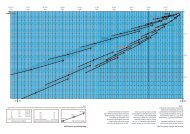
DIAMOND CHAIN PERFORMANCE<br />
Extra link plate<br />
capacity <strong>of</strong> Diamond<br />
chain is a result <strong>of</strong><br />
detail to pitch hole<br />
preparation <strong>and</strong> <strong>of</strong><br />
shot peening<br />
external su<strong>rf</strong>aces.<br />
HIGHER CAPACITIES – HIGHER SPEEDS<br />
Extra roller/bushing capacity <strong>of</strong> Diamond<br />
chain is a result <strong>of</strong> formed bushings <strong>and</strong> solid<br />
rollers which have more pe<strong>rf</strong>ect roundness<br />
<strong>and</strong> grain structure orientation.<br />
Roller Chain Horsepower Ratings<br />
Per ANSI St<strong>and</strong>ards B29.1.<br />
S P R O C K E T R . P. M .<br />
If your application is one which exceeds the<br />
ANSI Horsepower ratings, please contact<br />
Diamond for suggestions or recommendations.<br />
Chains must be selected based upon loads that they can transmit repeatedly over millions <strong>of</strong> cycles.<br />
So, chains with equal tensile strengths can, <strong>and</strong> commonly do, have very diff e rent working load capacities.<br />
In fact, chains with higher published tensile strengths than Diamond could easily have much lower<br />
working load capacities.<br />
WHY USE ROLLER CHAIN?<br />
D U R A B I L I T Y – Roller chain drives give long service life because the chain load is distributed over<br />
several sprocket teeth, keeping bearing pre s s u res relatively low for the power transmitted.<br />
R U G G E D N E S S – The pro p o rtions, parts heat treatment, <strong>and</strong> press-fit construction <strong>of</strong> roller chains<br />
help them withst<strong>and</strong> shock loads <strong>and</strong> rough drive conditions.<br />
E F F I C I E N C Y – Roller chains transmit power with high efficiency throughout the entire life <strong>of</strong> the<br />
drive. There are no large separating forces, radial loads, thrusts, or bearing pre s s u res to waste power.<br />
T h e re f o re, machine frames <strong>and</strong> bearings may be smaller, lighter <strong>and</strong> less costly.<br />
V E R S AT I L I T Y – Drive center distances may be long or short, fixed or adjustable, to suit machine design.<br />
Roller chain can transmit power to several shafts from a single drive shaft. Roller chains can engage spro c k-<br />
ets on either side <strong>and</strong> drive sprockets in either direction. Roller chains operate efficiently over a wide speed<br />
range in minimum space.<br />
C O N V E N I E N C E – Chain installation re q u i res only the alignment that can be readily obtained with commonly<br />
available h<strong>and</strong> tools. Roller chains can be easily connected <strong>and</strong> disconnected with st<strong>and</strong>ard connecting<br />
links. Roller chains can be replaced or maintained without disturbing the sprockets, shafts or bearings.<br />
P R E C I S I O N – Diamond roller chains are manufactured with great precision. Close control <strong>of</strong> chain l e n g t h ,<br />
roller diameters <strong>and</strong> other critical dimensions contribute to smooth, quiet action <strong>and</strong> high eff i c i e n c y.<br />
11
www.diamondchain.com<br />
A CHAIN IS ONLY WORTH ITS WEAKEST LINK<br />
Let’s face it, there are less expensive chains out there, but are they worth it? Probably not in the long<br />
run. In most cases, cheap chain doesn’t last as long so you have to replace it more <strong>of</strong>ten. That means<br />
downtime <strong>and</strong> all <strong>of</strong> the costs associated with it: idle workers, lost production, repair/replacement<br />
costs – it all adds up. Don’t be fooled. Initial costs aren’t necessarily real costs. Here’s an example work<br />
sheet that will help you underst<strong>and</strong> the real costs associated with less expensive chain. Please take the<br />
time with your Diamond Chain representative or distributor to complete the example using chains <strong>and</strong><br />
costs that reflect your specific drive conditions. It will clearly illustrate that the investment in Diamond<br />
roller chain is definitely worth it when compared to the long-term repair <strong>and</strong> replacement costs <strong>of</strong> a<br />
less expensive chain.<br />
ANNUAL CHAIN COST ANALYSIS<br />
BARGAIN CHAIN<br />
DIAMOND CHAIN<br />
A. Unit cost <strong>of</strong> new chain ($/chain-Ft): _______ _______<br />
B. Length required for application (chain-Ft): _______ _______<br />
C. Chain cost per application, A x B ($/chain): _______ _______<br />
D. Chains used per year (chains/Yr): _______ _______<br />
E. Annual cost <strong>of</strong> chains, C x D ($/Yr): _______ _______<br />
F. Chain repairs per year (repairs/Yr): _______ _______<br />
G. Average hours <strong>of</strong> downtime per repair<br />
(downtime-Hrs/repair): _______ _______<br />
H. Costs per downtime-hour, including<br />
cost <strong>of</strong> repair labor, lost efficiency,<br />
lost pr<strong>of</strong>its, etc. ($/downtime-Hr): _______ _______<br />
I. Annual downtime costs, F x G x H ($/Yr): _______ _______<br />
J. Total annual costs incurred, E + I ($/Yr): _______ _______<br />
12<br />
Nothing outlasts a Diamond. ®
STANDARD SERIES CHAIN<br />
Chain Descriptions <strong>and</strong> Dimensions<br />
St<strong>and</strong>ard Series Chain<br />
www.diamondchain.com<br />
Though it’s referred to as st<strong>and</strong>ard chain, it’s anything but. Our St<strong>and</strong>ard Series chains, built to ASME/ANSI B29.1<br />
st<strong>and</strong>ards, are manufactured to very specific requirements. The only thing st<strong>and</strong>ard about our chains are their<br />
ability to fit many st<strong>and</strong>ard applications. From industry to agriculture, our St<strong>and</strong>ard Series chains are designed<br />
to last longer than any other manufacturer’s roller chain.<br />
Dimensions in Inches <strong>and</strong> Pounds<br />
ASME/ANSI Pitch Roller Roller Pin Link Plate C R K Weight Per Average<br />
Number Inches Width Diameter Diameter Thickness Foot Tensile Strength<br />
25 1<br />
/4<br />
25-2 1<br />
/4<br />
25-3 1<br />
/4<br />
35 3<br />
/8<br />
35-2 3<br />
/8<br />
35-3 3<br />
/8<br />
35-4 3<br />
/8<br />
35-5 3<br />
/8<br />
35-6 3<br />
/8<br />
40 1<br />
/2<br />
40-2 1<br />
/2<br />
40-3 1<br />
/2<br />
40-4 1<br />
/2<br />
40-6 1<br />
/2<br />
41 1<br />
/2<br />
50 5<br />
/8<br />
50-2 5<br />
/8<br />
50-3 5<br />
/8<br />
50-4 5<br />
/8<br />
50-5 5<br />
/8<br />
50-6 5<br />
/8<br />
50-8 5<br />
/8<br />
50-10 5<br />
/8<br />
60 3<br />
/4<br />
60-2 3<br />
/4<br />
60-3 3<br />
/4<br />
60-4 3<br />
/4<br />
60-5 3<br />
/4<br />
60-6 3<br />
/4<br />
60-8 3<br />
/4<br />
60-10 3<br />
/4<br />
1<br />
/8 *.130 .090 .030 .37 .34 .... .084 875<br />
1<br />
/8 *.130 .090 .030 .63 .59 .252 .163 1750<br />
1<br />
/8 *.130 .090 .030 .88 .84 .252 .246 2625<br />
3<br />
/16 *.200 .141 .050 .56 .50 .... .210 2100<br />
3<br />
/16 *.200 .141 .050 .96 .90 .399 .450 4200<br />
3<br />
/16 *.200 .141 .050 1.36 1.31 .399 .680 6300<br />
3<br />
/16 *.200 .141 .050 1.76 1.70 .399 .910 8400<br />
3<br />
/16 *.200 .141 .050 2.16 2.11 .399 1.140 10500<br />
3<br />
/16 *.200 .141 .050 2.57 2.51 .399 1.370 12600<br />
5<br />
/16 .312 .156 .060 .72 .67 .... .410 4000<br />
5<br />
/16 .312 .156 .060 1.29 1.24 .566 .800 8000<br />
5<br />
/16 .312 .156 .060 1.85 1.80 .566 1.200 12000<br />
5<br />
/16 .312 .156 .060 2.42 2.37 .566 1.600 16000<br />
5<br />
/16 .312 .156 .060 3.56 3.51 .566 2.420 24000<br />
1<br />
/4 .306 .141 .050 .65 .57 .... .260 2400<br />
3<br />
/8 .400 .200 .080 .89 .83 .... .680 6600<br />
3<br />
/8 .400 .200 .080 1.60 1.55 .713 1.320 13200<br />
3<br />
/8 .400 .200 .080 2.31 2.26 .713 1.980 19800<br />
3<br />
/8 .400 .200 .080 3.03 2.97 .713 2.640 26400<br />
3<br />
/8 .400 .200 .080 3.75 3.69 .713 3.300 33000<br />
3<br />
/8 .400 .200 .080 4.46 4.40 .713 3.960 39600<br />
3<br />
/8 .400 .200 .080 5.89 5.83 .713 5.300 52800<br />
3<br />
/8 .400 .200 .080 7.32 7.26 .713 6.620 66000<br />
1<br />
/2 .469 .234 .094 1.11 1.04 .... .990 8500<br />
1<br />
/2 .469 .234 .094 2.01 1.94 .897 1.950 17000<br />
1<br />
/2 .469 .234 .094 2.91 2.84 .897 2.880 25500<br />
1<br />
/2 .469 .234 .094 3.81 3.74 .897 3.900 34000<br />
1<br />
/2 .469 .234 .094 4.71 4.64 .897 4.970 42500<br />
1<br />
/2 .469 .234 .094 5.60 5.53 .897 5.960 51000<br />
1<br />
/2 .469 .234 .094 7.40 7.33 .897 7.940 68000<br />
1<br />
/2 .469 .234 .094 9.19 9.12 .897 9.920 85000<br />
* Chains are rollerless — dimension shown is bushing diameter. Chart continues on next page.<br />
ASME/ANSI 60 <strong>and</strong> larger chains are available as cottered or riveted type design.<br />
Multiple str<strong>and</strong> chains are available with slip-fit (st<strong>and</strong>ard) or press-fit center plates.<br />
14
STANDARD SERIES CHAIN<br />
Chain Descriptions <strong>and</strong> Dimensions<br />
317-638-6431<br />
1-800-US-CHAIN<br />
Dimensions in Inches <strong>and</strong> Pounds<br />
Chart continued from previous page.<br />
ASME/ANSI Pitch Roller Roller Pin Link Plate C R K Weight Per Average<br />
Number Inches Width Diameter Diameter Thickness Foot Tensile Strength<br />
80 1 5<br />
/8 .625 .312 .125 1.44 1.32 .... 1.73 14500<br />
80-2 1 5<br />
/8 .625 .312 .125 2.59 2.47 1.153 3.37 29000<br />
80-3 1 5<br />
/8 .625 .312 .125 3.74 3.62 1.153 5.02 43500<br />
80-4 1 5<br />
/8 .625 .312 .125 4.90 4.79 1.153 6.73 58000<br />
80-5 1 5<br />
/8 .625 .312 .125 6.06 5.94 1.153 8.40 72500<br />
80-6 1 5<br />
/8 .625 .312 .125 7.22 7.10 1.153 10.07 87000<br />
80-8 1 5<br />
/8 .625 .312 .125 9.53 9.40 1.153 13.41 116000<br />
100 1 1 /4<br />
3<br />
/4 .750 .375 .156 1.73 1.61 .... 2.51 24000<br />
100-2 1 1 /4<br />
3<br />
/4 .750 .375 .156 3.14 3.02 1.408 4.91 48000<br />
100-3 1 1 /4<br />
3<br />
/4 .750 .375 .156 4.56 4.43 1.408 7.40 72000<br />
100-4 1 1 /4<br />
3<br />
/4 .750 .375 .156 5.97 5.84 1.408 9.80 96000<br />
100-5 1 1 /4<br />
3<br />
/4 .750 .375 .156 7.38 7.25 1.408 12.20 120000<br />
100-6 1 1 /4<br />
3<br />
/4 .750 .375 .156 8.78 8.66 1.408 14.60 144000<br />
100-8 1 1 /4<br />
3<br />
/4 .750 .375 .156 11.60 11.48 1.408 19.40 192000<br />
120 1 1 /2 1 .875 .437 .187 2.14 2.00 .... 3.69 34000<br />
120-2 1 1 /2 1 .875 .437 .187 3.93 3.79 1.789 7.35 68000<br />
120-3 1 1 /2 1 .875 .437 .187 5.72 5.58 1.789 11.10 102000<br />
120-4 1 1 /2 1 .875 .437 .187 7.52 7.38 1.789 14.70 136000<br />
120-5 1 1 /2 1 .875 .437 .187 9.31 9.17 1.789 18.43 170000<br />
120-6 1 1 /2 1 .875 .437 .187 11.10 10.96 1.789 22.11 204000<br />
120-8 1 1 /2 1 .875 .437 .187 14.68 14.54 1.789 29.47 272000<br />
120-10 1 1 /2 1 .875 .437 .187 18.26 18.12 1.789 36.83 340000<br />
140 1 3 /4 1 1.000 .500 .219 2.31 2.14 .... 5.00 46000<br />
140-2 1 3 /4 1 1.000 .500 .219 4.24 4.07 1.924 9.65 92000<br />
140-3 1 3 /4 1 1.000 .500 .219 6.16 6.00 1.924 14.30 138000<br />
140-4 1 3 /4 1 1.000 .500 .219 8.09 7.93 1.924 18.95 184000<br />
140-6 1 3 /4 1 1.000 .500 .219 11.94 11.78 1.924 28.25 276000<br />
160 2 1 1 /4 1.125 .562 .250 2.73 2.54 .... 6.53 58000<br />
160-2 2 1 1 /4 1.125 .562 .250 5.04 4.85 2.305 12.83 116000<br />
160-3 2 1 1 /4 1.125 .562 .250 7.35 7.16 2.305 19.03 174000<br />
160-4 2 1 1 /4 1.125 .562 .250 9.66 9.47 2.305 25.60 232000<br />
160-6 2 1 1 /4 1.125 .562 .250 14.27 14.09 2.305 37.78 348000<br />
180 2 1 /4 1 13 /32 1.406 .687 .281 3.15 2.88 .... 9.06 76000<br />
180-2 2 1 /4 1 13 /32 1.406 .687 .281 5.75 5.48 2.592 17.67 152000<br />
180-3 2 1 /4 1 13 /32 1.406 .687 .281 8.34 8.07 2.592 26.20 228000<br />
200 2 1 /2 1 1 /2 1.562 .781 .312 3.44 3.12 .... 10.65 95000<br />
200-2 2 1 /2 1 1 /2 1.562 .781 .312 6.26 5.94 2.817 21.50 190000<br />
200-3 2 1 /2 1 1 /2 1.562 .781 .312 9.08 8.76 2.817 32.30 285000<br />
200-4 2 1 /2 1 1 /2 1.562 .781 .312 11.90 11.58 2.817 42.90 380000<br />
200-6 2 1 /2 1 1 /2 1.562 .781 .312 17.52 17.21 2.817 64.50 570000<br />
240 3 1 7 /8 1.875 .937 .375 4.32 3.83 .... 17.03 157600<br />
240-2 3 1 7 /8 1.875 .937 .375 7.77 7.27 3.458 33.44 315200<br />
240-3 3 1 7 /8 1.875 .937 .375 11.23 10.73 3.458 49.77 472800<br />
15
HEAVY SERIES CHAIN<br />
Chain Descriptions <strong>and</strong> Dimensions<br />
Heavy Series Chain<br />
www.diamondchain.com<br />
Heavy Series chains, also built in accordance with ASME/ANSI B29.1, are designed using link plate material from<br />
the next larger size chain. Heavy Series chains are not necessarily stronger than St<strong>and</strong>ard Series chains, but the<br />
thicker link plate material provides an increase in fatigue resistance for those drives subjected to heavy shock<br />
loads, multiple stops/starts or reversing.<br />
Dimensions in Inches <strong>and</strong> Pounds<br />
ASME/ANSI Pitch Roller Roller Pin Link Plate C R K Weight Per Average<br />
Number Inches Width Diameter Diameter Thickness Foot Tensile Strength<br />
60H 3<br />
/4<br />
1<br />
/2 .469 .234 .125 1.24 1.17 .... 1.18 8500<br />
60H-2 3<br />
/4<br />
1<br />
/2 .469 .234 .125 2.27 2.20 1.028 2.33 17000<br />
60H-3 3<br />
/4<br />
1<br />
/2 .469 .234 .125 3.31 3.24 1.028 3.47 25500<br />
60H-4 3<br />
/4<br />
1<br />
/2 .469 .234 .125 4.34 4.26 1.028 4.61 34000<br />
80H 1 5<br />
/8 .625 .312 .156 1.57 1.45 .... 2.02 14500<br />
80H-2 1 5<br />
/8 .625 .312 .156 2.84 2.72 1.283 3.93 29000<br />
80H-3 1 5<br />
/8 .625 .312 .156 4.14 4.02 1.283 5.92 43500<br />
80H-4 1 5<br />
/8 .625 .312 .156 5.42 5.30 1.283 7.87 58000<br />
100H 1 1 /4<br />
3<br />
/4 .750 .375 .187 1.86 1.74 .... 2.82 24000<br />
100H-2 1 1 /4<br />
3<br />
/4 .750 .375 .187 3.41 3.28 1.539 5.58 48000<br />
100H-3 1 1 /4<br />
3<br />
/4 .750 .375 .187 4.95 4.82 1.539 8.32 72000<br />
100H-4 1 1 /4<br />
3<br />
/4 .750 .375 .187 6.49 6.37 1.539 11.04 96000<br />
120H 1 1 /2 1 .875 .437 .219 2.27 2.13 .... 4.08 34000<br />
120H-2 1 1 /2 1 .875 .437 .219 4.20 4.06 1.924 8.04 68000<br />
120H-3 1 1 /2 1 .875 .437 .219 6.13 5.99 1.924 11.99 102000<br />
120H-4 1 1 /2 1 .875 .437 .219 8.06 7.92 1.924 15.94 136000<br />
120H-6 1 1 /2 1 .875 .437 .219 11.91 11.77 1.924 23.84 204000<br />
140H 1 3 /4 1 1.000 .500 .250 2.44 2.28 .... 5.40 46000<br />
140H-2 1 3 /4 1 1.000 .500 .250 4.50 4.34 2.055 10.65 92000<br />
140H-3 1 3 /4 1 1.000 .500 .250 6.56 6.39 2.055 15.90 138000<br />
140H-4 1 3 /4 1 1.000 .500 .250 8.62 8.45 2.055 21.10 184000<br />
160H 2 1 1 /4 1.125 .562 .281 2.86 2.68 .... 7.03 58000<br />
160H-2 2 1 1 /4 1.125 .562 .281 5.30 5.12 2.436 13.88 116000<br />
160H-3 2 1 1 /4 1.125 .562 .281 7.75 7.56 2.436 20.68 174000<br />
160H-4 2 1 1 /4 1.125 .562 .281 10.17 10.00 2.436 27.62 232000<br />
180H 2 1 /4 1 13 /32 1.406 .687 .312 3.28 3.01 .... 9.59 76000<br />
180H-2 2 1 /4 1 13 /32 1.406 .687 .312 6.00 5.73 2.723 18.86 152000<br />
180H-3 2 1 /4 1 13 /32 1.406 .687 .312 8.73 8.46 2.723 28.14 228000<br />
200H 2 1 /2 1 1 /2 1.562 .781 .375 3.71 3.39 .... 13.38 <strong>110</strong>000<br />
200H-2 2 1 /2 1 1 /2 1.562 .781 .375 6.79 6.48 3.083 26.38 220000<br />
200H-3 2 1 /2 1 1 /2 1.562 .781 .375 9.88 9.56 3.083 40.85 330000<br />
240H 3 1 7 /8 1.875 .937 .500 4.85 4.35 ... 21.08 157600<br />
ASME/ANSI 60 <strong>and</strong> larger chains are available as cottered or riveted type design.<br />
Multiple str<strong>and</strong> chains are available with slip-fit (st<strong>and</strong>ard) or press-fit center plates.<br />
16
NON-STANDARD SERIES CHAIN<br />
Chain Descriptions <strong>and</strong> Dimensions<br />
Non-st<strong>and</strong>ard Series Chain<br />
317-638-6431<br />
1-800-US-CHAIN<br />
Prior to the ASME/ANSI st<strong>and</strong>ards, Diamond Chain produced many chains having unique dimensions, <strong>of</strong>ten for very<br />
specific applications. After industry’s adoption <strong>of</strong> ASME/ANSI st<strong>and</strong>ards many <strong>of</strong> these chains became the current<br />
St<strong>and</strong>ard or Heavy Series chains, but some did not. Diamond recognizes that a considerable amount <strong>of</strong> industrial<br />
equipment still utilizes these unique chains <strong>and</strong> so whenever possible we continue to produce them. The information<br />
below may be useful in identifying your “non-st<strong>and</strong>ard, but still very important” model.<br />
Dimensions in Inches <strong>and</strong> Pounds<br />
Diamond Other Pitch Roller Roller Pin Link Plate C R K Weight Per Average<br />
Number ID Inches Width Diameter Diameter Thickness Foot Tensile Strength<br />
61 x 3 ⁄ 16 1 3<br />
⁄ 16 .325 .141 .040 .47 .43 .... .22 1600<br />
65 x 1 ⁄ 8 BS #4 1<br />
⁄ 2 1<br />
⁄ 8 .306 .141 .040 .46 .42 .... .18 2250<br />
867 BS #7 1<br />
⁄ 2 5<br />
⁄ 16 .335 .174 .060 .73 .68 .... .43 4200<br />
148 x 1 ⁄ 4 BS #10 5<br />
⁄ 8 1<br />
⁄ 4 .400 .200 .080 .73 .67 .... .59 6600<br />
148 x 5 ⁄ 16 5<br />
⁄ 8 5<br />
⁄ 16 .400 .200 .080 .86 .74 .... .64 6600<br />
433 x 3 ⁄ 8 3<br />
⁄ 4 3<br />
⁄ 8 .469 .234 .094 .98 .91 .... .91 8500<br />
435 x 3 ⁄ 8 1 3<br />
⁄ 8 .562 .281 .125 1.14 1.05 .... 1.11 9000<br />
435 x 1 ⁄ 2 1 1<br />
⁄ 2 .562 .281 .125 1.27 1.18 .... 1.21 9000<br />
472 1 1 ⁄ 2 3<br />
⁄ 4 .875 .437 .187 1.86 1.72 .... 3.40 34000<br />
472-2 1 1 ⁄ 2 3<br />
⁄ 4 .875 .437 .187 3.45 3.30 1.55 6.76 68000<br />
472-3 1 1 ⁄ 2 3<br />
⁄ 4 .875 .437 .187 5.00 4.85 1.55 10.08 102000<br />
472-4 1 1 ⁄ 2 3<br />
⁄ 4 .875 .437 .187 6.55 6.41 1.55 13.40 136000<br />
264 64S 2 1 ⁄ 2 1 1 ⁄ 2 1.562 .875 .375 3.71 3.39 .... 13.68 148500<br />
264-3 64S-3 2 1 ⁄ 2 1 1 ⁄ 2 1.562 .875 .375 9.88 9.56 3.083 40.92 445500<br />
61 x 3 /16 uses an alternating pitch <strong>of</strong> .6 <strong>and</strong> .4 inches. Consult Diamond for 65 x 1 /8 st<strong>and</strong>ard attachment availability.<br />
Link Plate Height<br />
Many times chains are contained within guides or extrusions to protect them from contamination. If this is the case,<br />
link plate height can be a critical dimension. The following charts represent nominal pin <strong>and</strong> roller link plate heights for<br />
the models shown. If more detailed information is required please contact Diamond’s application engineers.<br />
Dimensions in Inches<br />
Link Plate<br />
Model Number<br />
Height* #25 #35 #40 #41 #50 #60 #80 #100 #120 #140 #160 #180 #200 #240<br />
E .205 .308 .410 .310 .512 .615 .820 1.025 1.230 1.435 1.640 1.845 2.050 2.422<br />
H .238 .356 .475 .383 .594 .713 .950 1.188 1.425 1.663 1.900 2.138 2.375 2.806<br />
* Nominal values are shown. For information on specific models contact Diamond.<br />
Dimensions in Inches<br />
Link Plate<br />
Model Number<br />
Height* #60H #80H #100H #120H #140H #160H #180H #200H #240H<br />
E .615 .820 1.025 1.230 1.435 1.640 1.845 2.050 2.422<br />
H .713 .950 1.188 1.425 1.663 1.900 2.138 2.375 2.806<br />
* Nominal values are shown. For information on specific models contact Diamond.<br />
17
OBSOLETE CHAIN<br />
Chain Descriptions <strong>and</strong> Dimensions<br />
www.diamondchain.com<br />
Obsolete Chain<br />
We have produced several types <strong>of</strong> chain, <strong>and</strong> for various reasons some <strong>of</strong> those chains were determined to be<br />
impractical to produce. We regret that all <strong>of</strong> these chains are no longer in production, but if your chain happens to<br />
be one <strong>of</strong> these, assistance from Diamond’s application engineers can <strong>of</strong>ten provide a practical replacement chain.<br />
The following information is <strong>of</strong>fered for reference only.<br />
Dimensions in Inches <strong>and</strong> Pounds<br />
Diamond Other Pitch Roller Roller Pin Link Plate C R K Weight Per Average<br />
Number ID Inches Width Diameter Diameter Thickness Foot Tensile Strength<br />
88 05B-1 8mm 1<br />
⁄ 8 .197 .090 .030 .37 .34 .... .12 1300<br />
61 x 1 ⁄ 4 1 1<br />
⁄ 4 .306 .141 .050 .61 .57 .... .26 1900<br />
65 x 3 ⁄ 16 1<br />
⁄ 2 3<br />
⁄ 16 .306 .141 .040 .47 .43 .... .21 2250<br />
433 x 5 ⁄ 16 3<br />
⁄ 4 5<br />
⁄ 16 .469 .234 .094 .92 .85 .... .85 8500<br />
433 x 5 ⁄ 8 3<br />
⁄ 4 5<br />
⁄ 8 .469 .234 .094 1.23 1.16 .... 1.09 8500<br />
435 x 5 ⁄ 8 1 5<br />
⁄ 8 .562 .281 .125 1.39 1.30 .... 1.31 9000<br />
434 x 1 ⁄ 2 1 1<br />
⁄ 2 .625 .312 .125 1.31 1.19 .... 1.61 14500<br />
431 x 1 ⁄ 2 1 1 ⁄ 4 1<br />
⁄ 2 .625 .312 .125 1.31 1.19 .... 1.33 <strong>110</strong>00<br />
431 x 5 ⁄ 8 1 1 ⁄ 4 5<br />
⁄ 8 .625 .312 .125 1.44 1.32 .... 1.43 <strong>110</strong>00<br />
437 x 3 ⁄ 4 1 1 ⁄ 2 3<br />
⁄ 4 .750 .375 .156 1.73 1.61 .... 2.23 24000<br />
18
DOUBLE-PITCH<br />
POWER TRANSMISSION<br />
ROLLER CHAIN<br />
Chain Descriptions <strong>and</strong> Dimensions<br />
Double-Pitch Power Transmission Roller Chain<br />
www.diamondchain.com<br />
These chains, produced to ASME/ANSI B29.3, have figure-eight style link plates. Their dimensions are similar to<br />
St<strong>and</strong>ard Series chains with the exception <strong>of</strong> the pitch, which is twice that <strong>of</strong> the St<strong>and</strong>ard Series. The increase<br />
in pitch means that only half the number <strong>of</strong> component parts are required per foot which can significantly lower<br />
the cost. Typical uses for these types <strong>of</strong> chains include light load drives commonly found in agriculture.<br />
Dimensions in Inches <strong>and</strong> Pounds<br />
ASME/ANSI Pitch Roller Roller Pin Link Pate C R Weight Per Average<br />
Number Inches Width Diameter Diameter Thickness Foot Tensile Strength<br />
2040 1 5<br />
⁄ 16 .312 .156 .060 .76 .68 .28 3700<br />
2050 1 1 ⁄ 4 3<br />
⁄ 8 .400 .200 .080 .92 .84 .52 6100<br />
2060 1 1 ⁄ 2 1<br />
⁄ 2 .469 .234 .094 1.11 1.05 .72 8500<br />
2080 2 5<br />
⁄ 8 .625 .312 .125 1.44 1.32 1.13 14500<br />
Link Plate Height<br />
Many times chains are contained within guides or extrusions to protect them from contamination. If this is the<br />
case, link plate height can be a critical dimension. The following represent nominal pin <strong>and</strong> roller link plate heights<br />
for the models shown. If more detailed information is required please contact Diamond’s application engineers.<br />
Dimensions in Inches<br />
Link Plate<br />
Model Number<br />
Height* 2040 2050 2060 2080<br />
H .475 .594 .712 .950<br />
* Nominal values are shown. For information on specific models contact Diamond.<br />
20
DOUBLE-PITCH<br />
CONVEYOR ROLLER CHAIN<br />
Chain Descriptions <strong>and</strong> Dimensions<br />
Double-Pitch Conveyor Roller Chain<br />
317-638-6431<br />
1-800-US-CHAIN<br />
Produced to ASME/ANSI B29.4, these chains are used in conveyor applications when loads are low <strong>and</strong> speeds<br />
are moderate. They are similar to the Double-Pitch Power Transmission chains, but with link plates that have an<br />
oval contour, <strong>and</strong> can be produced with either st<strong>and</strong>ard or over-sized rollers. They are most <strong>of</strong>ten found working<br />
on conveyors <strong>of</strong> all shapes <strong>and</strong> sizes <strong>and</strong> can be supplied with one or more <strong>of</strong> our many attachments to carry or<br />
convey products.<br />
Dimensions in Inches <strong>and</strong> Pounds<br />
ASME/ANSI Pitch Roller Roller Pin Link Plate C R Weight Per Average<br />
Number Inches Width Diameter Diameter Thickness Foot Tensile Strength<br />
C-2040 1 5<br />
⁄ 16 .312 .156 .060 .76 .68 .34 3700<br />
C-2050 1 1 ⁄ 4 3<br />
⁄ 8 .400 .200 .080 .92 .84 .58 6100<br />
C-2060H 1 1 ⁄ 2 1<br />
⁄ 2 .469 .234 .125 1.25 1.18 1.05 8500<br />
C-2080H 2 5<br />
⁄ 8 .625 .312 .156 1.57 1.45 1.40 14500<br />
C-2100H 2 1 ⁄ 2 3<br />
⁄ 4 .750 .375 .187 1.86 1.74 2.48 24000<br />
C-2120H 3 1 .875 .437 .219 2.27 2.13 3.60 34000<br />
C-2160H 4 1 1 ⁄ 4 1.125 .562 .281 2.86 2.68 6.18 58000<br />
Dimensions in Inches <strong>and</strong> Pounds<br />
ASME/ANSI Pitch Roller Roller Pin Link Plate C R Weight Per Average<br />
Number Inches Width Diameter Diameter Thickness Foot Tensile Strength<br />
C-2042 1 5<br />
/16 .625 .156 .060 .76 .68 .50 3700<br />
C-2052 1 1 /4<br />
3<br />
/8 .750 .200 .080 .92 .84 .81 6100<br />
C-2062H 1 1 /2<br />
1<br />
/2 .875 .234 .125 1.25 1.18 1.42 8500<br />
C-2082H 2 5<br />
/8 1.125 .312 .156 1.57 1.45 2.13 14500<br />
C-2102H 2 1 /2<br />
3<br />
/4 1.562 .375 .187 1.86 1.74 3.51 24000<br />
C-2122H 3 1 1.750 .437 .219 2.27 2.13 5.48 34000<br />
C-2162H 4 1 1 /4 2.250 .562 .281 2.86 2.68 9.34 58000<br />
Link Plate Height<br />
Many times chains are contained within guides or extrusions to protect them from contamination. If this is the<br />
case, link plate height can be a critical dimension. The following represent nominal pin <strong>and</strong> roller link plate heights<br />
for the models shown. If more detailed information is required please contact Diamond’s application engineers.<br />
Dimensions in Inches<br />
Link<br />
Model Number<br />
Plate C2040 C2050 C2060H C2080H C2100H C2120H C2160H<br />
Height* C2062H C2082H C2102H C2122H C2162H<br />
H .475 .594 .712 .950 1.187 1.425 1.900<br />
* Nominal values are shown. For information on specific models contact Diamond.<br />
21
STANDARD ATTACHMENT<br />
ROLLER CHAIN<br />
Chain Descriptions <strong>and</strong> Dimensions<br />
www.diamondchain.com<br />
St<strong>and</strong>ard Attachment Roller Chain<br />
Single- <strong>and</strong> Double-Pitch chains are available assembled with either attachment link plates or extended pins. While most carbon steel<br />
attachment chains fall within Diamond’s Attachment Chain Program <strong>and</strong> ship in 48 hours (for quantities up to 100 feet) in 3-5 working<br />
days (for quantities <strong>of</strong> 101 to 300 feet) or in 5-7 working days (for quantities <strong>of</strong> 301 to 500 feet), stainless steel, nickel-plated <strong>and</strong> ACE coated<br />
attachment chains also get special attention through Diamond's 5-day shipping program. These attachments' shapes <strong>and</strong> sizes are "st<strong>and</strong>ard"<br />
their uses are limited only by your imagination. Now the chain that lasts the longest, arrives the fastest because from the minute you place your<br />
order, we have from 48 hours to 5 days to get it out the door. That way you don’t wait -- wasting countless dollars in downtime.<br />
When designing or specifying attachment chains, consider the following information to avoid problems with either<br />
installation or pe<strong>rf</strong>o<strong>rmance</strong>.<br />
St<strong>and</strong>ard Attachments: St<strong>and</strong>ard attachments described on the following pages are normally much less expensive<br />
than special designs. However, if a specialty attachment is necessary please refer to the Made-To-Order section <strong>of</strong><br />
this guide or contact Diamond’s application engineers for possible design options.<br />
Link Plate Location: Attachments, regardless <strong>of</strong> st<strong>and</strong>ard or special design, assembled on pin links are less<br />
expensive than those assembled on roller links.<br />
Modifications: Diamond’s attachment link plates are specifically designed <strong>and</strong> heat treated to permit further operations<br />
by the user such as drilling, reaming, <strong>and</strong> tapping if desired. At no time should attachment links be modified by<br />
welding because the heat applied can adversely affect the heat treatment <strong>of</strong> the steel, resulting in either reduced<br />
pe<strong>rf</strong>o<strong>rmance</strong> or failure.<br />
Extended Pins: Extended pins, made from medium carbon steel, are specially heat treated for ductility <strong>and</strong> toughness<br />
<strong>and</strong> can be easily assembled at virtually any spacing. It is important to note that if pairs <strong>of</strong> extended pins are<br />
specified, they must be located in a common pin link. In some applications this may require the use <strong>of</strong> an <strong>of</strong>fset in the<br />
cycle.<br />
Diamond does not recommend using “shouldered pins.” They are generally expensive to manufacture <strong>and</strong> can <strong>of</strong>ten<br />
compromise quality due to high stress concentrations at the point where diameters change. Additions <strong>of</strong> sleeves or<br />
bearings on the extended pins will <strong>of</strong>ten yield a more dependable design <strong>and</strong> at a lower cost.<br />
Attachment Hole Sizes: Diamond’s st<strong>and</strong>ard attachment hole sizes are designed to accommodate the most<br />
common screw sizes. If your application requires a different attachment hole size, than shown in this section, please<br />
contact Diamond, as many alternate lug holes are available <strong>and</strong> may be available from stock.<br />
Dimensions in Inches<br />
Chain Hole Screw Screw<br />
Size Diameter Size Diameter<br />
25 .125 #3 .099<br />
35 .102 #2 .086<br />
40 .141 #5 .125<br />
41 .141 #5 .125<br />
50 .203 #10 .190<br />
60 .203 #10 .190<br />
80 .266 1<br />
⁄ 4 .250<br />
100 .343 5<br />
⁄ 16 .312<br />
120 .386 3<br />
⁄ 8 .375<br />
140 .448 7<br />
⁄ 16 .438<br />
160 .516 1<br />
⁄ 2 .500<br />
Dimensions in Inches<br />
Chain Hole Screw Screw<br />
Size Diameter* Size Diameter<br />
C2040 .141 # 5 .125<br />
C2050 .203 #10 .190<br />
C2060H .203 #10 .190<br />
C2080H .266 1<br />
⁄ 4 .250<br />
C2100H .328 5<br />
⁄ 16 .312<br />
C2120H .391 3<br />
⁄ 8 .375<br />
C2160H .516 1<br />
⁄ 2 .500<br />
*Straight, one hole attachments have larger diameters than shown. Refer to Double-<br />
Pitch Straight <strong>and</strong> Bent Attachment tables for more detail.<br />
24
STANDARD ATTACHMENT<br />
ROLLER CHAIN<br />
Chain Descriptions <strong>and</strong> Dimensions<br />
317-638-6431<br />
1-800-US-CHAIN<br />
Assembly: While it is possible to purchase base chain or attachment components <strong>and</strong> construct an attachment<br />
chain, it is strongly recommended that chains be ordered <strong>and</strong> assembled at the factory to ensure the proper fit<br />
<strong>and</strong> alignment <strong>of</strong> all parts along with any length or matching requirements.<br />
Manufacturing Length Tolerance: ASME/ANSI defines the permissible length <strong>of</strong> an assembled section <strong>of</strong><br />
roller chain. The allowable length tolerances vary from model to model <strong>and</strong> are also affected by the chain’s<br />
construction, i.e., with or without attachments.<br />
As an example, the assembled length tolerance for an ASME/ANSI one inch pitch chain (#80) is +.016"/-.000"<br />
per foot. When attachments are added to the chain’s design, the tolerance for length exp<strong>and</strong>s to +.032"/-.000"<br />
per foot. This means that a section <strong>of</strong> #80 chain 12 pitches long (12" nominal) can measure as long as 12.016"<br />
but no less than 12.000". The same section <strong>of</strong> chain assembled with bent, straight, or extended pin attachments<br />
could measure as long as 12.032" but again, no less than 12.000".<br />
In common practice, manufacturers strive to produce chain nearer to the nominal figure, but the maximum allowable<br />
length tolerance should always be considered when designing for take-ups <strong>and</strong> catenary chain sag. If the<br />
application requires it, some design <strong>and</strong> assembly steps can be taken to direct the length <strong>of</strong> the chain toward<br />
the nominal. However, on a routine basis machine designs based on a nominal or specified chain length should<br />
be avoided.<br />
Length Matching <strong>of</strong> Roller Chains: Many applications require two or more chains, normally with attachments,<br />
to run in parallel with “flights” joining the chains together forming a conveyor or transfer type system. In these<br />
cases it is critical to have the chains ordered as a set, matched for length <strong>and</strong> installed on the machinery with the<br />
same relationship to one another as when they were manufactured.<br />
Diamond <strong>of</strong>fers two degrees <strong>of</strong> matching for parallel operation: Class I <strong>and</strong> Class II.<br />
Class I - A Class I match assures that the longest <strong>and</strong> the shortest chain in a given set will not vary in overall<br />
length by more than .006"/ft. Again using #80 chain as an example, the length <strong>of</strong> two #80 chains 120 pitches<br />
long will not vary by more than .060" in overall length (10ft. x .006"/ft. = .060"). The shortest could measure<br />
120" + .000" (remember, no negative tolerance) <strong>and</strong> the longest could measure up to 120" + .060" <strong>and</strong> satisfy<br />
the Class I requirement. Class I matching is most <strong>of</strong>ten accomplished by assembling the chains from selected lots<br />
<strong>of</strong> component parts.<br />
Class II - A Class II match is much more stringent <strong>and</strong> assures that the longest <strong>and</strong> the shortest chain in a given<br />
set will not vary in overall length by more than .002"/ft. Applying this new tolerance to the above example, the<br />
length <strong>of</strong> two #80 chains 120 pitches long will not vary by more than .020" in overall length (10ft. x .002"/ft. =<br />
.020"). The shortest could measure 120" + .000" <strong>and</strong> the longest could measure 120" + .020" <strong>and</strong> satisfy the<br />
requirement. Class II matching is quite difficult <strong>and</strong> requires some very unique procedures.<br />
Differences - It is important to remember that matched chains still fall under the overall length limitations imposed<br />
by either ASME/ANSI or the manufacturer. Matching does not assure the user <strong>of</strong> chains with a finite overall<br />
length, only that the chains in the set have a controlled relationship to one another.<br />
25
STANDARD ATTACHMENT<br />
ROLLER CHAIN<br />
Chain Descriptions <strong>and</strong> Dimensions<br />
www.diamondchain.com<br />
St<strong>and</strong>ard Straight <strong>and</strong> Bent Attachment Chain<br />
R<br />
R<br />
H<br />
H<br />
L<br />
D<br />
T<br />
T<br />
L<br />
D<br />
T<br />
T<br />
S<br />
K<br />
R<br />
WI<br />
X<br />
WO<br />
Others<br />
M-35, SA1<br />
M-1, SK1<br />
Diamond<br />
S1 (one hole)<br />
S2 (one hole)<br />
PITCH<br />
Dimensions in Inches<br />
Others<br />
A1<br />
K1<br />
Diamond<br />
B1 (one hole)<br />
B2 (one hole)<br />
ASME/ANSI Pitch R<br />
Number Inches D H K L Max. S T WI WO X<br />
25 .250 .125 .180 .451 .218 .119 .308 .030 .781 .843 .562<br />
35 .375 .102 .250 .577 .312 .178 .387 .050 1.125 1.125 .750<br />
40 .500 .141 .312 .684 .375 .238 .489 .060 1.390 1.390 1.000<br />
41 .500 .141 .282 .698 .375 .192 .482 .050 1.375 1.375 .937<br />
50 .625 .203 .406 .895 .500 .297 .618 .080 1.812 1.812 1.250<br />
60 .750 .203 .478 1.038 .625 .356 .716 .094 2.135 2.135 1.500<br />
80 1.000 .266 .625 1.339 .750 .475 .968 .125 2.750 2.750 2.000<br />
100 1.250 .343 .784 1.696 1.000 .594 1.233 .156 3.077 3.406 2.500<br />
120 1.500 .386 .917 2.024 1.125 .713 1.424 .187 3.841 4.239 2.995<br />
140 1.750 .448 1.127 2.445 1.375 .831 1.750 .220 4.361 4.826 3.500<br />
160 2.000 .516 1.250 2.756 1.500 .950 2.007 .250 5.078 5.609 4.000<br />
Above attachments available for multiple str<strong>and</strong> chain.<br />
Wide Contour Straight <strong>and</strong> Bent Attachment Chain<br />
Lw<br />
P*<br />
T<br />
T<br />
T<br />
P*<br />
D<br />
D<br />
Sw<br />
K<br />
X<br />
W<br />
R<br />
PITCH<br />
Lw<br />
D<br />
Hw<br />
R<br />
T<br />
Hw<br />
R<br />
Others<br />
WM-35<br />
WM-35-2<br />
Diamond<br />
WCS1 (one hole)<br />
WCS1 (two holes)<br />
Others<br />
WM-1<br />
WM-2<br />
Diamond<br />
WCS2 (one hole)<br />
WCS2 (two holes)<br />
Dimensions in Inches<br />
Others<br />
WA-1<br />
WA-2, A2<br />
Diamond<br />
WCB1 (one hole)<br />
WCB1 (two holes)<br />
Others<br />
WK-1<br />
WK-2, K2<br />
Diamond<br />
WCB2 (one hole)<br />
WCB2 (two holes)<br />
26<br />
ASME/ANSI Pitch R<br />
Number Inches D Hw K Lw P Max. Sw T W X<br />
*35 .375 .125 .262 .577 .727 .375 .178 .399 .050 1.105 .750<br />
*40 .500 .141 .326 .684 .946 .500 .238 .503 .060 1.366 1.000<br />
*41 .500 .141 .282 .698 .878 .500 .192 .482 .050 1.372 .937<br />
*50 .625 .203 .406 .895 1.211 .625 .297 .618 .080 1.807 1.250<br />
*60 .750 .203 .478 1.038 1.420 .750 .356 .716 .094 2.135 1.500<br />
*80 1.000 .266 .625 1.339 1.885 1.000 .475 .967 .125 2.750 2.000<br />
*†100 1.250 .343 .784 1.696 2.362 1.250 .594 1.233 .156 3.408 2.500<br />
*†120 1.500 .386 .917 2.023 2.836 1.500 .713 1.424 .187 4.239 2.995<br />
* Attachment available on pin link plate only.<br />
† These items not available with 48-hour delivery.<br />
Contact Diamond Chain for available attachments on roller links (wide contour).<br />
Above attachments available for mutiple str<strong>and</strong> chain.
STANDARD ATTACHMENT<br />
ROLLER CHAIN<br />
Chain Descriptions <strong>and</strong> Dimensions<br />
317-638-6431<br />
1-800-US-CHAIN<br />
Double-Pitch Bent Attachments<br />
Oval Contour Link Plates<br />
St<strong>and</strong>ard <strong>and</strong> <strong>Over</strong>sized Roller<br />
H<br />
H<br />
L<br />
H<br />
H<br />
T<br />
D<br />
D<br />
T<br />
A<br />
WI<br />
X<br />
WO<br />
X<br />
Others<br />
A1<br />
A2<br />
Diamond<br />
B1 (one hole)<br />
B1 (two holes)<br />
T<br />
B<br />
PITCH<br />
Dimensions in Inches<br />
T<br />
Others<br />
K1<br />
K2<br />
Diamond<br />
B2 (one hole)<br />
B2 (two holes)<br />
St<strong>and</strong>ard Roller Pitch Large Roller<br />
ASME/ANSI # Roller Diam. Inches A B D H L T WI WO X ASME/ANSI # Roller Diam.<br />
*C2040 .312 1.00 .500 .375 .141 .359 .750 .060 1.350 1.483 1.000 C-2042 .625<br />
*C2050 .400 1.25 .625 .469 .203 .453 .937 .080 1.692 1.863 1.250 C-2052 .750<br />
*C2060H .469 1.50 .844 .562 .203 .578 1.125 .125 2.171 2.446 1.688 C-2062H .875<br />
*C2080H .625 2.00 1.094 .750 .266 .766 1.500 .156 2.792 3.125 2.188 C-2082H 1.125<br />
*C2100H .750 2.50 1.312 .937 .328 .922 1.875 .187 3.554 3.951 2.625 C-2102H 1.562<br />
*C2120H .875 3.00 1.562 1.125 .391 1.095 2.250 .219 4.318 4.782 3.125 C-2122H 1.750<br />
*C2160H 1.125 4.00 2.063 1.500 .516 1.438 3.000 .281 5.520 6.116 4.125 C-2162H 2.250<br />
*Two attachment holes stock.<br />
One attachment hole made-to-order.<br />
Double-Pitch Straight Attachments<br />
Oval Contour Link Plates<br />
St<strong>and</strong>ard <strong>and</strong> <strong>Over</strong>sized Roller<br />
L<br />
T<br />
T<br />
B<br />
D1<br />
D<br />
T<br />
T<br />
S1<br />
K<br />
S<br />
Others<br />
M-35, SA1<br />
M-35-2, SA2<br />
Diamond<br />
S1 (one hole)<br />
S1 (two holes)<br />
*Two attachment holes stock.<br />
One attachment hole made-to-order.<br />
PITCH<br />
Dimensions in Inches<br />
Others<br />
M-1, SK1<br />
M-2, SK2<br />
Diamond<br />
S2 (one hole)<br />
S2 (two holes)<br />
St<strong>and</strong>ard Roller With Two* Attachment Holes<br />
With One<br />
Attachment Hole Large Roller<br />
ASME/ Roller Pitch ASME/ Roller<br />
ANSI # Diam. Inches B D S K L T D1 S1 ANSI # Diam.<br />
*C2040 .312 1.00 .375 .141 .531 .773 .750 .060 .188 .438 C-2042 .625<br />
*C2050 .400 1.25 .469 .203 .625 .971 .937 .080 .250 .563 C-2052 .750<br />
*C2060H .469 1.50 .562 .203 .750 1.203 1.125 .125 .329 .688 C-2062H .875<br />
*C2080H .625 2.00 .750 .266 1.000 1.590 1.500 .156 .375 .875 C-2082H 1.125<br />
*C2100H .750 2.50 .937 .328 1.250 1.982 1.875 .187 .516 1.125 C-2102H 1.562<br />
*C2120H .875 3.00 1.125 .391 1.469 2.367 2.250 .219 .563 1.312 C-2122H 1.750<br />
*C2160H 1.125 4.00 1.500 .516 2.000 3.090 3.000 .281 .750 1.750 C-2162H 2.250<br />
27
STANDARD ATTACHMENT<br />
ROLLER CHAIN<br />
Chain Descriptions <strong>and</strong> Dimensions<br />
www.diamondchain.com<br />
St<strong>and</strong>ard Extended Pins<br />
For ASME/ANSI St<strong>and</strong>ard Series Chains<br />
Double-Pitch Conveyor Chains<br />
D<br />
D<br />
D<br />
L<br />
L<br />
L<br />
Others<br />
D1<br />
D3<br />
Diamond<br />
E1 (one extended pin)<br />
E2 (two extended pins)<br />
Dimensions in Inches<br />
ASME/ Pitch<br />
ANSI # Inches D±.0005" L±.010"<br />
35 .375 .141 .375<br />
40 .500 .156 .383<br />
41 .500 .141 .375<br />
50 .625 .200 .468<br />
60 .750 .234 .562<br />
ASME Pitch<br />
ANSI # Inches D±.0005" L±.010"<br />
80 1.00 .312 .750<br />
100 1.25 .375 .937<br />
120 1.50 .437 1.125<br />
140 1.75 .500 1.312<br />
160 2.00 .562 1.500<br />
ASME/ANSI #<br />
Pitch<br />
Inches D±.0005" L±.010"<br />
C-2040, C-2042 1.00 .156 .375<br />
C-2050, C-2052 1.25 .200 .468<br />
C-2060H, C-2062H 1.50 .234 .562<br />
C-2080H, C-2082H 2.00 .312 .750<br />
C-2100H, C-2102H 2.50 .375 .937<br />
C-2120H, C-2122H 3.00 .437 1.125<br />
C-2160H, C-2162H 4.00 .562 1.500<br />
St<strong>and</strong>ard Attachment Terminology Other Diamond Description<br />
Manufacturers<br />
Terminology<br />
Single- <strong>and</strong> Double-Pitch Lugs A1 B1 one hole Bent attachment, one side, one hole<br />
A2 B1 two holes Bent attachment, one side, two holes<br />
K1 B2 one hole Bent attachment, both sides, one hole<br />
K2 B2 two holes Bent attachment, both sides, two holes<br />
SA1, M-35 S1 one hole Straight attachment, one side, one hole<br />
SA2, M-35-2 S1 two holes Straight attachment, one side, two holes<br />
SK1, M-1 S2 one hole Straight attachment, both sides, one hole<br />
SK2, M-2 S2 two holes Straight attachment, both sides, two holes<br />
Wide Contour Lugs WM-35 WCS1 one hole Wide contour, straight attachment, one side, one hole<br />
WM-35-2 WCS1 two holes Wide contour, straight attachment, one side, two holes<br />
WM-1 WCS2 one hole Wide contour, straight attachment, both sides, one hole<br />
WM-2 WCS2 two holes Wide contour, straight attachment, both sides, two holes<br />
WA-1 WCB1 one hole Wide contour, bent attachment, one side, one hole<br />
WA-2, A2 WCB1 two holes Wide contour, bent attachment, one side, two holes<br />
WK-1 WCB2 one hole Wide contour, bent attachment, both sides, one hole<br />
WK-2, K2 WCB2 two holes Wide contour, bent attachment, both sides, two holes<br />
Extended Pins D1 E1 One pin in link extended<br />
D3 E2 Both pins in link extended<br />
28
MULTIPLE STRAND CHAIN<br />
Chain Descriptions <strong>and</strong> Dimensions<br />
www.diamondchain.com<br />
Diamond Multiple Str<strong>and</strong> Roller Chain<br />
When the loads or speeds are too great for a single str<strong>and</strong> chain to carry, multiple str<strong>and</strong> roller chain, which is the<br />
equivalent <strong>of</strong> two or more single str<strong>and</strong> chains assembled with common pins, can <strong>of</strong>ten provide the necessary<br />
capacity. These chains are manufactured in several widths, depending upon the specific model, up to twelve<br />
str<strong>and</strong>s wide. Diamond’s multiple str<strong>and</strong> chains are available with two types <strong>of</strong> construction – with center plates<br />
slip-fit on the pins or with center plates press-fit on the pins.<br />
Slip-fit center plate: Slip-fit center plate multiple str<strong>and</strong> chains have been used for decades <strong>and</strong> are most<br />
suitable for drives <strong>of</strong> moderate severity. These chains are designed for ease <strong>of</strong> disassembly throughout the entire<br />
length <strong>of</strong> chain. The chains can be shortened or sections can be added quickly with minimal effort. However, with<br />
the slip-fit design, the user may experience accelerated fatigue failures in exchange for the ease <strong>of</strong> alteration<br />
in the field.<br />
Press-fit center plate: Press-fit multiple str<strong>and</strong> chains were originally developed by Diamond for service in<br />
applications that require the utmost in multiple str<strong>and</strong> chain capacity. Multiple str<strong>and</strong> chains with press-fit center<br />
plates have significantly greater fatigue strength than their slip-fit center plate counterparts, because press-fit<br />
construction assures rigid, permanent support for the pins at each tension point with no relative movement, which<br />
can cause wear or fatigue.<br />
The superiority <strong>of</strong> press-fit center plate chain over the slip-fit center plate chain has been proven many, many<br />
times in actual service where the drive conditions are severe. The extreme durability <strong>and</strong> ruggedness <strong>of</strong> Diamond<br />
multiple str<strong>and</strong> roller chains are exemplified by their wide acceptance for use on such heavy-duty equipment as<br />
power shovels, diesel engines, <strong>and</strong> oil drilling <strong>and</strong> pumping units.<br />
While the press-fit construction does provide the increased fatigue resistance that is essential in many applications,<br />
the user does give up some convenience because the chain’s length is not readily shortened in the field.<br />
For this reason press-fit center plate chains should always be ordered in the exact pitch length required,<br />
including a Bushed Center Plate Link (BCL) connecting link.<br />
30
MULTIPLE STRAND CHAIN<br />
Chain Descriptions <strong>and</strong> Dimensions<br />
317-638-6431<br />
1-800-US-CHAIN<br />
Bushed Center Plate Links (BCL): With the development <strong>of</strong> the BCL connecting link for press-fit center plate<br />
chains almost fifty <strong>years</strong> ago, Diamond made a significant engineering advance. These links have virtually the<br />
same superior durability <strong>and</strong> high resistance to fatigue found only in press-fit center plate chain, yet they are as<br />
easily installed <strong>and</strong> removed as slip-fit center plate type connecting links.<br />
The BCL connecting link is constructed using center plate assemblies, consisting <strong>of</strong> two center plates securely<br />
held together with two press-fit bushings. These bushings, hardened to resist wear, have inside diameters<br />
precision ground after assembly into the center plates. The grinding tolerances are extremely close with respect<br />
to both the pitch dimension <strong>and</strong> hole size to assure a close sliding-fit on the chain pins.<br />
These features reduce to a minimum the possibility <strong>of</strong> any relative motion between pins <strong>and</strong> bushings <strong>and</strong> assures<br />
equal distribution <strong>of</strong> chain-load across pins throughout the service-life <strong>of</strong> the chain.<br />
Diamond BCL connecting links are available for 5 ⁄ 8 " through 2- 1 ⁄ 2 " pitch St<strong>and</strong>ard Series, press-fit center plate<br />
multiple-str<strong>and</strong> chain.<br />
The cost <strong>of</strong> manufacturing BCL connecting links is unavoidably higher than that <strong>of</strong> slip-fit center plate links,<br />
but the greater durability <strong>and</strong> high resistance to fatigue more than warrants the additional cost.<br />
Bushed Center Plate Assembly<br />
Four-Pitch Press-Fit Offset Link Assembly: Pins are press-fit in <strong>of</strong>fset link pitch holes. Four-pitch length<br />
permits the use <strong>of</strong> BCL connecting links on either end, giving maximum capacity <strong>of</strong> chain assembly.<br />
31
MULTIPLE STRAND CHAIN<br />
Chain Descriptions <strong>and</strong> Dimensions<br />
www.diamondchain.com<br />
BCL Connecting Link<br />
BCL Connecting Link<br />
One End <strong>of</strong> Chain 5-Pitch Section <strong>of</strong> Chain Other End <strong>of</strong> Chain<br />
4-Pitch Offset Link Assembly<br />
3-Pitch Section <strong>of</strong> Chain<br />
When the ability to shorten press-fit center plate multiple str<strong>and</strong> chain is a requirement, it is recommended that the<br />
original chain be ordered to the exact length needed in pitches including two connecting links <strong>of</strong> the BCL type,<br />
with a five-pitch section <strong>of</strong> the chain between the two.<br />
When the chain has elongated through normal wear the equivalent <strong>of</strong> one pitch, the five-pitch section <strong>of</strong> chain<br />
should be replaced by a four-pitch <strong>of</strong>fset link assembly, which has press-fit link plates throughout, providing<br />
maximum structural rigidity.<br />
When subsequent wear-elongation is sufficient to allow the removal <strong>of</strong> another pitch <strong>of</strong> chain, the four-pitch<br />
<strong>of</strong>fset link assembly should be replaced by a three-pitch section <strong>of</strong> press-fit center plate chain.<br />
Similarly, should a drive on fixed centers require an odd number <strong>of</strong> pitches in the original chain length, the chain<br />
should be specified to include a four-pitch <strong>of</strong>fset link assembly between two BCL connecting links. To shorten<br />
the chain by the equivalent <strong>of</strong> one pitch, the four-pitch <strong>of</strong>fset link assembly should be replaced with a<br />
three-pitch section <strong>of</strong> press-fit center plate chain.<br />
In general, the use <strong>of</strong> <strong>of</strong>fset links in any chain design should be avoided whenever possible due to the decreased<br />
load carrying ability <strong>of</strong> the <strong>of</strong>fset. However, if an <strong>of</strong>fset must be employed, the use <strong>of</strong> a two- or four-pitch <strong>of</strong>fset link<br />
assembly in multiple str<strong>and</strong> chains, especially press-fit center plate chain, is preferred over one-pitch <strong>of</strong>fset links.<br />
Single-pitch <strong>of</strong>fsets do not provide the desirable structural rigidity found in the two- <strong>and</strong> four-pitch assemblies.<br />
32
MULTIPLE STRAND CHAIN<br />
Chain Descriptions <strong>and</strong> Dimensions<br />
317-638-6431<br />
1-800-US-CHAIN<br />
Dimensions in Inches <strong>and</strong> Pounds<br />
ASME/ANSI Pitch Roller Roller Pin Link Plate C R K Weight Per Average<br />
Number Inches Width Diameter Diameter Thickness Foot Tensile Strength<br />
25-2 1<br />
⁄ 4 1<br />
⁄ 8 *.130 .090 .030 .63 .59 .252 .163 1750<br />
25-3 1<br />
⁄ 4 1<br />
⁄ 8 *.130 .090 .030 .88 .84 .252 .246 2625<br />
35-2 3<br />
⁄ 8 3<br />
⁄ 16 *.200 .141 .050 .96 .90 .399 .450 4200<br />
35-3 3<br />
⁄ 8 3<br />
⁄ 16 *.200 .141 .050 1.36 1.31 .399 .680 6300<br />
35-4 3<br />
⁄ 8 3<br />
⁄ 16 *.200 .141 .050 1.76 1.70 .399 .910 8400<br />
35-5 3<br />
⁄ 8 3<br />
⁄ 16 *.200 .141 .050 2.16 2.11 .399 1.140 10500<br />
35-6 3<br />
⁄ 8 3<br />
⁄ 16 *.200 .141 .050 2.57 2.51 .399 1.370 12600<br />
40-2 1<br />
⁄ 2 5<br />
⁄ 16 .312 .156 .060 1.29 1.24 .566 .800 8000<br />
40-3 1<br />
⁄ 2 5<br />
⁄ 16 .312 .156 .060 1.85 1.80 .566 1.200 12000<br />
40-4 1<br />
⁄ 2 5<br />
⁄ 16 .312 .156 .060 2.42 2.37 .566 1.600 16000<br />
40-6 1<br />
⁄ 2 5<br />
⁄ 16 .312 .156 .060 3.56 3.51 .566 2.420 24000<br />
50-2 5<br />
⁄ 8 3<br />
⁄ 8 .400 .200 .080 1.60 1.55 .713 1.320 13200<br />
50-3 5<br />
⁄ 8 3<br />
⁄ 8 .400 .200 .080 2.31 2.26 .713 1.980 19800<br />
50-4 5<br />
⁄ 8 3<br />
⁄ 8 .400 .200 .080 3.03 2.97 .713 2.640 26400<br />
50-5 5<br />
⁄ 8 3<br />
⁄ 8 .400 .200 .080 3.75 3.69 .713 3.300 33000<br />
50-6 5<br />
⁄ 8 3<br />
⁄ 8 .400 .200 .080 4.46 4.40 .713 3.960 39600<br />
50-8 5<br />
⁄ 8 3<br />
⁄ 8 .400 .200 .080 5.89 5.83 .713 5.300 52800<br />
50-10 5<br />
⁄ 8 3<br />
⁄ 8 .400 .200 .080 7.32 7.26 .713 6.620 66000<br />
60-2 3<br />
⁄ 4 1<br />
⁄ 2 .469 .234 .094 2.01 1.94 .897 1.950 17000<br />
60-3 3<br />
⁄ 4 1<br />
⁄ 2 .469 .234 .094 2.91 2.84 .897 2.880 25500<br />
60-4 3<br />
⁄ 4 1<br />
⁄ 2 .469 .234 .094 3.81 3.74 .897 3.900 34000<br />
60-5 3<br />
⁄ 4 1<br />
⁄ 2 .469 .234 .094 4.71 4.64 .897 4.970 42500<br />
60-6 3<br />
⁄ 4 1<br />
⁄ 2 .469 .234 .094 5.60 5.53 .897 5.960 51000<br />
60-8 3<br />
⁄ 4 1<br />
⁄ 2 .469 .234 .094 7.40 7.33 .897 7.940 68000<br />
60-10 3<br />
⁄ 4 1<br />
⁄ 2 .469 .234 .094 9.19 9.12 .897 9.920 85000<br />
80-2 1 5<br />
⁄ 8 .625 .312 .125 2.59 2.47 1.153 3.370 29000<br />
80-3 1 5<br />
⁄ 8 .625 .312 .125 3.74 3.62 1.153 5.020 43500<br />
80-4 1 5<br />
⁄ 8 .625 .312 .125 4.90 4.79 1.153 6.730 58000<br />
80-5 1 5<br />
⁄ 8 .625 .312 .125 6.06 5.94 1.153 8.400 72500<br />
80-6 1 5<br />
⁄ 8 .625 .312 .125 7.22 7.10 1.153 10.070 87000<br />
80-8 1 5<br />
⁄ 8 .625 .312 .125 9.53 9.40 1.153 13.410 116000<br />
100-2 1 1 ⁄ 4 3<br />
⁄ 4 .750 .375 .156 3.14 3.02 1.408 4.910 48000<br />
100-3 1 1 ⁄ 4 3<br />
⁄ 4 .750 .375 .156 4.56 4.43 1.408 7.400 72000<br />
100-4 1 1 ⁄ 4 3<br />
⁄ 4 .750 .375 .156 5.97 5.84 1.408 9.800 96000<br />
100-5 1 1 ⁄ 4 3<br />
⁄ 4 .750 .375 .156 7.38 7.25 1.408 12.200 120000<br />
100-6 1 1 ⁄ 4 3<br />
⁄ 4 .750 .375 .156 8.78 8.66 1.408 14.600 144000<br />
100-8 1 1 ⁄ 4 3<br />
⁄ 4 .750 .375 .156 11.60 11.48 1.408 19.400 192000<br />
120-2 1 1 ⁄ 2 1 .875 .437 .187 3.93 3.79 1.789 7.350 68000<br />
120-3 1 1 ⁄ 2 1 .875 .437 .187 5.72 5.58 1.789 11.100 102000<br />
120-4 1 1 ⁄ 2 1 .875 .437 .187 7.52 7.38 1.789 14.700 136000<br />
120-5 1 1 ⁄ 2 1 .875 .437 .187 9.31 9.17 1.789 18.430 170000<br />
120-6 1 1 ⁄ 2 1 .875 .437 .187 11.10 10.96 1.789 22.<strong>110</strong> 204000<br />
120-8 1 1 ⁄ 2 1 .875 .437 .187 14.68 14.54 1.789 29.470 272000<br />
120-10 1 1 ⁄ 2 1 .875 .437 .187 18.26 18.12 1.789 36.830 340000<br />
* Chains are rollerless — dimension shown is bushing diameter. Chart continues on next page.<br />
ASME/ANSI 60 <strong>and</strong> larger chains are available as cottered or riveted type design.<br />
Multiple str<strong>and</strong> chains are available with slip-fit (st<strong>and</strong>ard) or press-fit center plates.<br />
33
MULTIPLE STRAND CHAIN<br />
Chain Descriptions <strong>and</strong> Dimensions<br />
www.diamondchain.com<br />
Dimensions in Inches <strong>and</strong> Pounds<br />
Chart continued from previous page.<br />
ASME/ANSI Pitch Roller Roller Pin Link Plate C R K Weight Per Average<br />
Number Inches Width Diameter Diameter Thickness Foot Tensile Strength<br />
140-2 1 3 ⁄ 4 1 1.000 .500 .219 4.24 4.07 1.924 9.65 92000<br />
140-3 1 3 ⁄ 4 1 1.000 .500 .219 6.16 6.00 1.924 14.30 138000<br />
140-4 1 3 ⁄ 4 1 1.000 .500 .219 8.09 7.93 1.924 18.95 184000<br />
140-6 1 3 ⁄ 4 1 1.000 .500 .219 11.94 11.78 1.924 28.25 276000<br />
160-2 2 1 1 ⁄ 4 1.125 .562 .250 5.04 4.85 2.305 12.83 116000<br />
160-3 2 1 1 ⁄ 4 1.125 .562 .250 7.35 7.16 2.305 19.03 174000<br />
160-4 2 1 1 ⁄ 4 1.125 .562 .250 9.66 9.47 2.305 25.60 232000<br />
160-6 2 1 1 ⁄ 4 1.125 .562 .250 14.27 14.09 2.305 37.78 348000<br />
180-2 2 1 ⁄ 4 1 13 ⁄ 32 1.406 .687 .281 5.75 5.48 2.592 17.67 152000<br />
180-3 2 1 ⁄ 4 1 13 ⁄ 32 1.406 .687 .281 8.34 8.07 2.592 26.20 228000<br />
200-2 2 1 ⁄ 2 1 1 ⁄ 2 1.562 .781 .312 6.26 5.94 2.817 21.50 190000<br />
200-3 2 1 ⁄ 2 1 1 ⁄ 2 1.562 .781 .312 9.08 8.76 2.817 32.30 285000<br />
200-4 2 1 ⁄ 2 1 1 ⁄ 2 1.562 .781 .312 11.90 11.58 2.817 42.90 380000<br />
200-6 2 1 ⁄ 2 1 1 ⁄ 2 1.562 .781 .312 17.52 17.21 2.817 64.50 570000<br />
240-2 3 1 7 ⁄ 8 1.875 .937 .375 7.77 7.27 3.458 33.44 315200<br />
240-3 3 1 7 ⁄ 8 1.875 .937 .375 11.23 10.73 3.458 49.77 472800<br />
ASME/ANSI 60 <strong>and</strong> larger chains are available as cottered or riveted type design.<br />
Multiple str<strong>and</strong> chains are available with slip-fit (st<strong>and</strong>ard) or press-fit center plates.<br />
34
HIGH STRENGTH/LIFT CHAIN<br />
Chain Descriptions <strong>and</strong> Dimensions<br />
www.diamondchain.com<br />
Produced in accordance with ASME/ANSI B29.1, these chains are designed for the rigors <strong>of</strong> heavy loads <strong>and</strong><br />
lifting. Depending on your specific application, Diamond <strong>of</strong>fers three options from which to choose.<br />
High Strength (HS) Drive Chains<br />
HS Series Drive chains are built in accordance with ASME/ANSI B29.1 <strong>and</strong> are dimensionally identical to Heavy<br />
Series Drive chains, but are specially designed <strong>and</strong> incorporate pins produced from medium carbon alloy steel.<br />
These pins are through-hardened to give the chain a higher working load capacity <strong>and</strong> additional resistance to<br />
fatigue in high load <strong>and</strong> pulsating type applications. Users <strong>of</strong> these chains should remember that wear life may be<br />
slightly reduced due to the material <strong>and</strong> heat treatment <strong>of</strong> the chain pins. Slip-fit type connecting links <strong>and</strong> <strong>of</strong>fset<br />
links are not available for these chains.<br />
Note: Offset links <strong>and</strong> slip-fit connecting links are not recommended for any High Strength or Lift Chain.<br />
Dimensions in Inches <strong>and</strong> Pounds<br />
Diamond Pitch Roller Roller Pin Link Plate C R Weight Per Average<br />
Number Inches Width Diameter Diameter Thickness Foot Tensile Strength<br />
60HS 3<br />
⁄ 4 1<br />
⁄ 2 .469 .234 .125 1.24 1.17 1.18 12000<br />
80HS 1 5<br />
⁄ 8 .625 .312 .156 1.57 1.45 2.02 21000<br />
100HS 1 1 ⁄ 4 3<br />
⁄ 4 .750 .375 .187 1.86 1.74 2.82 30000<br />
120HS 1 1 ⁄ 2 1 .875 .437 .219 2.27 2.13 4.08 41000<br />
140HS 1 3 ⁄ 4 1 1.000 .500 .250 2.44 2.28 5.40 56000<br />
160HS 2 1 1 ⁄ 4 1.125 .562 .281 2.86 2.68 7.03 70000<br />
180HS 2 1 ⁄ 4 1 13 ⁄ 32 1.406 .687 .312 3.28 3.01 9.59 95000<br />
200HS 2 1 ⁄ 2 1 1 ⁄ 2 1.562 .781 .375 3.71 3.39 13.75 136000<br />
200HS-2 2 1 ⁄ 2 1 1 ⁄ 2 1.562 .781 .375 6.79 6.48 26.38 270000<br />
200HS-3 2 1 ⁄ 2 1 1 ⁄ 2 1.562 .781 .375 9.88 9.56 40.85 405000<br />
240HS 3 1 7 ⁄ 8 1.875 .937 .500 4.85 4.35 21.08 157600<br />
For the ultimate in Diamond Chain High Strength pe<strong>rf</strong>o<strong>rmance</strong>,<br />
consider Diamond HS Oval Contour chains. Specially designed with<br />
pins produced from medium carbon alloy steel <strong>and</strong> FULL Oval<br />
Contour pin <strong>and</strong> roller link plates, providing the maximum link plate<br />
rigidity for high load fatigue applications.<br />
Note: Offset links <strong>and</strong> slip-fit connecting links are not recommended<br />
for any High Strength or Lift Chain.<br />
Dimensions in Inches <strong>and</strong> Pounds<br />
Diamond Pitch Roller Roller Pin Link Plate C R Weight Per Average<br />
Number Inches Width Diameter Diameter Thickness Foot Tensile Strength<br />
60HSOC 3<br />
⁄ 4 1<br />
⁄ 2 .469 .234 .125 1.24 1.17 1.42 12000<br />
80HSOC 1 5<br />
⁄ 8 .625 .312 .156 1.57 1.45 2.38 21000<br />
100HSOC 1 1 ⁄ 4 3<br />
⁄ 4 .750 .375 .187 1.86 1.74 3.29 30000<br />
36
HIGH STRENGTH/LIFT CHAIN<br />
Chain Descriptions <strong>and</strong> Dimensions<br />
Hoist Chain<br />
These chains are built in accordance with ASME/ANSI B29.24 <strong>and</strong> are dimensionally identical to St<strong>and</strong>ard Series<br />
Drive chains, but also incorporate pins produced from medium carbon alloy steel, through-hardened, to give the<br />
chains higher working load capacity <strong>and</strong> additional resistance to fatigue. Additionally, these chains are produced<br />
with solid rollers for increased pe<strong>rf</strong>o<strong>rmance</strong> when loading is high, but speeds are slow. Users <strong>of</strong> these chains<br />
should be aware that wear life may be slightly reduced due to the material <strong>and</strong> heat treatment <strong>of</strong> the chain pins.<br />
Note: Slip-fit type connecting links <strong>and</strong> <strong>of</strong>fset links are not available for these chains.<br />
317-638-6431<br />
1-800-US-CHAIN<br />
Dimensions in Inches <strong>and</strong> Pounds<br />
Diamond Pitch Roller Roller Pin Link Plate C R Weight Per Average<br />
Number Inches Width Diameter Diameter Thickness Foot Tensile Strength<br />
625 5<br />
/8<br />
750 3<br />
/4<br />
3<br />
/8 .400 .200 .080 .89 .83 .68 8000<br />
1<br />
/2 .469 .234 .094 1.11 1.04 .99 10500<br />
Rollerless Lift Chain<br />
These chains are specifically designed for tension linkages where frequent articulation requires the increased<br />
bearing area <strong>of</strong> a roller chain. Rollerless Lift chains are dimensionally identical to St<strong>and</strong>ard Series Drive chains but are produced<br />
without rollers.<br />
Note: Slip-fit type connecting links <strong>and</strong> <strong>of</strong>fset links are not available for these chains.<br />
Dimensions in Inches <strong>and</strong> Pounds<br />
Diamond Pitch Roller Roller Pin Link Plate C R Weight Per Average<br />
Number Inches Width Diameter Diameter Thickness Foot Tensile Strength<br />
55S 5<br />
/8<br />
3<br />
/8 *.280 .200 .080 .89 .83 .55 †8000<br />
65S 3<br />
/4<br />
1<br />
/2 *.332 .234 .094 1.11 1.04 .81 †10500<br />
85 1 5<br />
/8 *.442 .312 .125 1.44 1.32 1.41 14500<br />
105 1 1 /4<br />
3<br />
/4 *.532 .375 .156 1.73 1.61 2.08 24000<br />
125 1 1 /2 1 *.620 .437 .187 2.14 2.00 3.04 34000<br />
* Chains are rollerless — dimension shown is bushing diameter.<br />
† Numbers 55S <strong>and</strong> 65S are assembled with medium carbon through-hardened pins.<br />
37
HIGH STRENGTH/LIFT CHAIN<br />
Chain Descriptions <strong>and</strong> Dimensions<br />
www.diamondchain.com<br />
Terminal Fittings<br />
Diamond does not provide terminal fittings. We recommend that fittings be made <strong>of</strong> through-hardened steel, heat<br />
treated to RC 40-45. They should be machined accurately to ensure proper mating with chain link plates <strong>and</strong> to<br />
provide uniform loading across the width <strong>of</strong> the chain. Chains should always be attached to the terminal fittings<br />
using a press-fit style connecting link. Terminal fittings should be inspected regularly <strong>and</strong> the above conditions<br />
maintained. Worn, damaged or corroded chains <strong>and</strong>/or terminal fittings can lead to chain failure which may result<br />
in either personal injury or property damage.<br />
Dimensions in Inches<br />
Diamond Pitch W +.000 -.031 Pin Hole A (max.)<br />
Number Inches Diameter Diameter<br />
60 H or HS 3<br />
⁄ 4 .764 .234 .237 .375<br />
80 H or HS 1 .955 .312 .315 .500<br />
100 H or HS 1 1 ⁄ 4 1.141 .375 .378 .625<br />
120 H or HS 1 1 ⁄ 2 1.458 .437 .440 .750<br />
140 H or HS 1 3 ⁄ 4 1.523 .500 .503 .875<br />
160 H or HS 2 1.838 .562 .565 1.000<br />
180 H ot HS 2 1 ⁄ 4 2.058 .687 .690 1.125<br />
200 H or HS 2 1 ⁄ 2 2.285 .781 .784 1.250<br />
625 5<br />
⁄ 8 .542 .200 .203 .312<br />
750 3<br />
⁄ 4 .696 .234 .237 .375<br />
55 S* 5<br />
⁄ 8 .542 .200 .203 .312<br />
65 S* 3<br />
⁄ 4 .696 .234 .237 .375<br />
85* 1 .886 .312 .315 .500<br />
105* 1 1 ⁄ 4 1.076 .375 .378 .625<br />
125* 1 1 ⁄ 2 1.390 .437 .440 .750<br />
* Chains are roller less.<br />
38
OIL FIELD CHAIN<br />
Chain Descriptions <strong>and</strong> Dimensions<br />
www.diamondchain.com<br />
Roller chains used in the oil <strong>and</strong> natural gas industries are subjected to some <strong>of</strong> the greatest loads <strong>and</strong> harshest<br />
environments. These conditions are far more severe than usually found in industrial applications. These “Oil Field”<br />
chains can be either single str<strong>and</strong> or multiple str<strong>and</strong> <strong>and</strong> are typically constructed using Heavy Series components.<br />
We produce our Oil Field chains with the same attention to detail that goes into all our products, but additionally<br />
these models are subjected to the most up to date API (American Petroleum Institute) Specification<br />
7F pe<strong>rf</strong>o<strong>rmance</strong> testing. By examining the label on the box which proudly displays the API logo, users <strong>of</strong><br />
our chains can be certain they are receiving the highest quality, best-pe<strong>rf</strong>orming product available. Only<br />
those companies which have established quality systems, approved <strong>and</strong> routinely audited, are authorized to<br />
display this symbol.<br />
American<br />
Petroleum<br />
Institute<br />
The following list <strong>of</strong> chain sizes <strong>and</strong> configurations are those which meet or exceed the pe<strong>rf</strong>o<strong>rmance</strong> criteria defined in<br />
API Specification 7F. It is highly recommended that multiple str<strong>and</strong> chains used in oil field applications be constructed<br />
with press-fit center plates. More information about press-fit construction is available in the Multiple Str<strong>and</strong> section <strong>of</strong><br />
this product guide.<br />
40<br />
Dimensions in Inches <strong>and</strong> Pounds<br />
ASME/ANSI Pitch Roller Roller Pin Link Plate C R K Weight Per Average<br />
Number Inches Width Diameter Diameter Thickness Foot Tensile Strength<br />
40 1<br />
⁄ 2 5<br />
⁄ 16 .312 .156 .060 .72 .67 .41 4000<br />
40-2 1<br />
⁄ 2 5<br />
⁄ 16 .312 .156 .060 1.29 1.24 .566 .80 8000<br />
40-3 1<br />
⁄ 2 5<br />
⁄ 16 .312 .156 .060 1.85 1.80 .566 1.20 12000<br />
40-4 1<br />
⁄ 2 5<br />
⁄ 16 .312 .156 .060 2.42 2.37 .566 1.60 16000<br />
40-6 1<br />
⁄ 2 5<br />
⁄ 16 .312 .156 .060 3.56 3.51 .566 2.42 24000<br />
50 5<br />
⁄ 8 3<br />
⁄ 8 .400 .200 .080 .89 .83 --- .68 6600<br />
50-2 5<br />
⁄ 8 3<br />
⁄ 8 .400 .200 .080 1.60 1.55 .713 1.32 13200<br />
50-3 5<br />
⁄ 8 3<br />
⁄ 8 .400 .200 .080 2.31 2.26 .713 1.98 19800<br />
50-4 5<br />
⁄ 8 3<br />
⁄ 8 .400 .200 .080 3.03 2.97 .713 2.64 26400<br />
50-5 5<br />
⁄ 8 3<br />
⁄ 8 .400 .200 .080 3.75 3.69 .713 3.30 33000<br />
50-6 5<br />
⁄ 8 3<br />
⁄ 8 .400 .200 .080 4.46 4.40 .713 3.96 39600<br />
50-8 5<br />
⁄ 8 3<br />
⁄ 8 .400 .200 .080 5.89 5.83 .713 5.30 52800<br />
50-10 5<br />
⁄ 8 3<br />
⁄ 8 .400 .200 .080 7.32 7.26 .713 6.62 66000<br />
60 3<br />
⁄ 1 4 ⁄ 2 .469 .234 .094 1.11 1.04 --- .99 8500<br />
60H 3<br />
⁄ 1 4 ⁄ 2 .469 .234 .125 1.24 1.17 --- 1.18 8500<br />
60-2 3<br />
⁄ 4 1<br />
⁄ 2 .469 .234 .094 2.01 1.94 .897 1.95 17000<br />
60H-2 3<br />
⁄ 4 1<br />
⁄ 2 .469 .234 .125 2.27 2.20 1.028 2.33 17000<br />
60-3 3<br />
⁄ 4 1<br />
⁄ 2 .469 .234 .094 2.91 2.84 .897 2.88 25500<br />
60H-3 3<br />
⁄ 4 1<br />
⁄ 2 .469 .234 .125 3.31 3.24 1.028 3.47 25500<br />
60-4 3<br />
⁄ 4 1<br />
⁄ 2 .469 .234 .094 3.81 3.74 .897 3.90 34000<br />
60H-4 3<br />
⁄ 4 1<br />
⁄ 2 .469 .234 .125 4.34 4.26 1.028 4.61 34000<br />
60-5 3<br />
⁄ 4 1<br />
⁄ 2 .469 .234 .094 4.71 4.64 .897 4.97 42500<br />
60-6 3<br />
⁄ 4 1<br />
⁄ 2 .469 .234 .094 5.60 5.53 .897 5.96 51000<br />
60-8 3<br />
⁄ 4 1<br />
⁄ 2 .469 .234 .094 7.40 7.33 .897 7.94 68000<br />
60-10 3<br />
⁄ 4 1<br />
⁄ 2 .469 .234 .094 9.19 9.12 .897 9.92 85000<br />
ASME/ANSI 60 <strong>and</strong> larger chains are available as cottered or riveted type design.<br />
Multiple str<strong>and</strong> chains are available with slip-fit (st<strong>and</strong>ard) or press-fit center plates.<br />
---<br />
Chart continues on next page.
OIL FIELD CHAIN<br />
Chain Descriptions <strong>and</strong> Dimensions<br />
317-638-6431<br />
1-800-US-CHAIN<br />
Dimensions in Inches <strong>and</strong> Pounds<br />
Chart continued from previous page.<br />
ASME/ANSI Pitch Roller Roller Pin Link Plate C R K Weight Per Average<br />
Number Inches Width Diameter Diameter Thickness Foot Tensile Strength<br />
80 1 5<br />
⁄ 8 .625 .312 .125 1.44 1.32 1.73 14500<br />
80H 1 5<br />
⁄ 8 .625 .312 .156 1.57 1.45 --- 2.02 14500<br />
80-2 1 5<br />
⁄ 8 .625 .312 .125 2.59 2.47 1.153 3.37 29000<br />
80H-2 1 5<br />
⁄ 8 .625 .312 .156 2.84 2.72 1.283 3.93 29000<br />
80-3 1 5<br />
⁄ 8 .625 .312 .125 3.74 3.62 1.153 5.02 43500<br />
80H-3 1 5<br />
⁄ 8 .625 .312 .156 4.14 4.02 1.283 5.92 43500<br />
80-4 1 5<br />
⁄ 8 .625 .312 .125 4.90 4.79 1.153 6.73 58000<br />
80H-4 1 5<br />
⁄ 8 .625 .312 .156 5.42 5.30 1.283 7.87 58000<br />
80-5 1 5<br />
⁄ 8 .625 .312 .125 6.06 5.94 1.153 8.40 72500<br />
80-6 1 5<br />
⁄ 8 .625 .312 .125 7.22 7.10 1.153 10.07 87000<br />
80-8 1 5<br />
⁄ 8 .625 .312 .125 9.53 9.40 1.153 13.41 116000<br />
100 1 1 ⁄ 3 4 ⁄ 4 .750 .375 .156 1.73 1.61 --- 2.51 24000<br />
100H 1 1 ⁄ 3 4 ⁄ 4 .750 .375 .187 1.86 1.74 --- 2.82 24000<br />
100-2 1 1 ⁄ 4 3<br />
⁄ 4 .750 .375 .156 3.14 3.02 1.408 4.91 48000<br />
100H-2 1 1 ⁄ 4 3<br />
⁄ 4 .750 .375 .187 3.41 3.28 1.539 5.58 48000<br />
100-3 1 1 ⁄ 4 3<br />
⁄ 4 .750 .375 .156 4.56 4.43 1.408 7.40 72000<br />
100H-3 1 1 ⁄ 4 3<br />
⁄ 4 .750 .375 .187 4.95 4.82 1.539 8.32 72000<br />
100-4 1 1 ⁄ 4 3<br />
⁄ 4 .750 .375 .156 5.97 5.84 1.408 9.80 96000<br />
100H-4 1 1 ⁄ 4 3<br />
⁄ 4 .750 .375 .187 6.49 6.37 1.539 11.04 96000<br />
100-5 1 1 ⁄ 4 3<br />
⁄ 4 .750 .375 .156 7.38 7.25 1.408 12.20 120000<br />
100-6 1 1 ⁄ 4 3<br />
⁄ 4 .750 .375 .156 8.78 8.66 1.408 14.60 144000<br />
100-8 1 1 ⁄ 4 3<br />
⁄ 4 .750 .375 .156 11.60 11.48 1.408 19.40 192000<br />
120 1 1 ⁄ 2 1 .875 .437 .187 2.14 2.00 --- 3.69 34000<br />
120H 1 1 ⁄ 2 1 .875 .437 .219 2.27 2.13 --- 4.08 34000<br />
120-2 1 1 ⁄ 2 1 .875 .437 .187 3.93 3.79 1.789 7.35 68000<br />
120H-2 1 1 ⁄ 2 1 .875 .437 .219 4.20 4.06 1.924 8.04 68000<br />
120-3 1 1 ⁄ 2 1 .875 .437 .187 5.72 5.58 1.789 11.10 102000<br />
120H-3 1 1 ⁄ 2 1 .875 .437 .219 6.13 5.99 1.924 11.99 102000<br />
120-4 1 1 ⁄ 2 1 .875 .437 .187 7.52 7.38 1.789 14.70 136000<br />
120H-4 1 1 ⁄ 2 1 .875 .437 .219 8.06 7.92 1.924 15.94 136000<br />
120-5 1 1 ⁄ 2 1 .875 .437 .187 9.31 9.17 1.789 18.43 170000<br />
120-6 1 1 ⁄ 2 1 .875 .437 .187 11.10 10.96 1.789 22.11 204000<br />
120H-6 1 1 ⁄ 2 1 .875 .437 .219 11.91 11.77 1.924 23.84 204000<br />
120-8 1 1 ⁄ 2 1 .875 .437 .187 14.68 14.54 1.789 29.47 272000<br />
120-10 1 1 ⁄ 2 1 .875 .437 .187 18.26 18.12 1.789 36.83 340000<br />
140 1 3 ⁄ 4 1 1.000 .500 .219 2.31 2.14 --- 5.00 46000<br />
140H 1 3 ⁄ 4 1 1.000 .500 .250 2.44 2.28 --- 5.40 46000<br />
140-2 1 3 ⁄ 4 1 1.000 .500 .219 4.24 4.07 1.924 9.65 92000<br />
140H-2 1 3 ⁄ 4 1 1.000 .500 .250 4.50 4.34 2.055 10.65 92000<br />
140-3 1 3 ⁄ 4 1 1.000 .500 .219 6.16 6.00 1.924 14.30 138000<br />
140H-3 1 3 ⁄ 4 1 1.000 .500 .250 6.56 6.39 2.055 15.90 138000<br />
140-4 1 3 ⁄ 4 1 1.000 .500 .219 8.09 7.93 1.924 18.95 184000<br />
140H-4 1 3 ⁄ 4 1 1.000 .500 .250 8.62 8.45 2.055 21.10 184000<br />
140-6 1 3 ⁄ 4 1 1.000 .500 .219 11.94 11.78 1.924 28.25 276000<br />
ASME/ANSI 60 <strong>and</strong> larger chains are available as cottered or riveted type design.<br />
Chart continues on next page.<br />
Multiple str<strong>and</strong> chains are available with slip-fit (st<strong>and</strong>ard) or press-fit center plates.<br />
---<br />
41
OIL FIELD CHAIN<br />
Chain Descriptions <strong>and</strong> Dimensions<br />
www.diamondchain.com<br />
American<br />
Petroleum<br />
Institute<br />
Dimensions in Inches <strong>and</strong> Pounds<br />
Chart continued from previous page.<br />
ASME/ANSI Pitch Roller Roller Pin Link Plate C R K Weight Per Average<br />
Number Inches Width Diameter Diameter Thickness Foot Tensile Strength<br />
160 2 1 1 ⁄ 4 1.125 .562 .250 2.73 2.54 6.53 58000<br />
160H 2 1 1 ⁄ 4 1.125 .562 .281 2.86 2.68 --- 7.03 58000<br />
160-2 2 1 1 ⁄ 4 1.125 .562 .250 5.04 4.85 2.305 12.83 116000<br />
160H-2 2 1 1 ⁄ 4 1.125 .562 .281 5.30 5.12 2.436 13.88 116000<br />
160-3 2 1 1 ⁄ 4 1.125 .562 .250 7.35 7.16 2.305 19.03 174000<br />
160H-3 2 1 1 ⁄ 4 1.125 .562 .281 7.75 7.56 2.436 20.68 174000<br />
160-4 2 1 1 ⁄ 4 1.125 .562 .250 9.66 9.47 2.305 25.60 232000<br />
160H-4 2 1 1 ⁄ 4 1.125 .562 .281 10.17 10.00 2.436 27.62 232000<br />
160-6 2 1 1 ⁄ 4 1.125 .562 .250 14.27 14.09 2.305 37.78 348000<br />
180 2 1 ⁄ 4 1 13 ⁄ 32 1.406 .687 .281 3.15 2.88 --- 9.06 76000<br />
180H 2 1 ⁄ 4 1 13 ⁄ 32 1.406 .687 .312 3.28 3.01 --- 9.59 76000<br />
180-2 2 1 ⁄ 4 1 13 ⁄ 32 1.406 .687 .281 5.75 5.48 2.592 17.67 152000<br />
180H-2 2 1 ⁄ 4 1 13 ⁄ 32 1.406 .687 .312 6.00 5.73 2.723 18.86 152000<br />
180-3 2 1 ⁄ 4 1 13 ⁄ 32 1.406 .687 .281 8.34 8.07 2.592 26.20 228000<br />
180H-3 2 1 ⁄ 4 1 13 ⁄ 32 1.406 .687 .312 8.73 8.46 2.723 28.14 228000<br />
200 2 1 ⁄ 2 1 1 ⁄ 2 1.562 .781 .312 3.44 3.12 --- 10.65 95000<br />
200H 2 1 ⁄ 2 1 1 ⁄ 2 1.562 .781 .375 3.71 3.39 --- 13.38 <strong>110</strong>000<br />
200-2 2 1 ⁄ 2 1 1 ⁄ 2 1.562 .781 .312 6.26 5.94 2.817 21.50 190000<br />
200H-2 2 1 ⁄ 2 1 1 ⁄ 2 1.562 .781 .375 6.79 6.48 3.083 26.38 220000<br />
200-3 2 1 ⁄ 2 1 1 ⁄ 2 1.562 .781 .312 9.08 8.76 2.817 32.30 285000<br />
200H-3 2 1 ⁄ 2 1 1 ⁄ 2 1.562 .781 .375 9.88 9.56 3.083 40.85 330000<br />
200-4 2 1 ⁄ 2 1 1 ⁄ 2 1.562 .781 .312 11.90 11.58 2.817 42.90 380000<br />
200-6 2 1 ⁄ 2 1 1 ⁄ 2 1.562 .781 .312 17.52 17.21 2.817 64.50 570000<br />
240 3 1 7 ⁄ 8 1.875 .937 .375 4.32 3.83 .... 17.03 157600<br />
240H 3 1 7 ⁄ 8 1.875 .937 .500 4.85 4.35 .... 21.08 157600<br />
240-2 3 1 7 ⁄ 8 1.875 .937 .375 7.77 7.27 3.458 33.44 315200<br />
240-3 3 1 7 ⁄ 8 1.875 .937 .375 11.23 10.73 3.458 49.77 472800<br />
ASME/ANSI 60 <strong>and</strong> larger chains are available as cottered or riveted type design.<br />
Multiple str<strong>and</strong> chains are available with slip-fit (st<strong>and</strong>ard) or press-fit center plates.<br />
---<br />
42
OIL FIELD CHAIN<br />
Chain Descriptions <strong>and</strong> Dimensions<br />
317-638-6431<br />
1-800-US-CHAIN<br />
Additionally, Diamond produces a narrow width 1- 1 ⁄ 2 " pitch roller chain for some <strong>of</strong> the older rigs <strong>and</strong> associated<br />
equipment as well as 2- 1 ⁄ 2 " pitch chain with a special larger pin diameter. These chains do not fall under the<br />
ASME/ANSI st<strong>and</strong>ards <strong>and</strong> therefore are not covered by API. Diamond still produces these non-st<strong>and</strong>ard chain to<br />
the highest quality st<strong>and</strong>ards, ensuring its superior pe<strong>rf</strong>o<strong>rmance</strong>.<br />
Dimensions in Inches <strong>and</strong> Pounds<br />
Diamond Other Pitch Roller Roller Pin Link Plate C R K Weight Per Average<br />
Number ID Inches Width Diameter Diameter Thickness Foot Tensile Strength<br />
472 .... 1 1 ⁄ 2 3<br />
⁄ 4 .875 .437 .187 1.93 1.80 .... 3.41 34000<br />
472-2 .... 1 1 ⁄ 2 3<br />
⁄ 4 .875 .437 .187 3.45 3.30 1.55 6.76 68000<br />
472-3 .... 1 1 ⁄ 2 3<br />
⁄ 4 .875 .437 .187 5.00 4.85 1.55 10.08 102000<br />
472-4 .... 1 1 ⁄ 2 3<br />
⁄ 4 .875 .437 .187 6.55 6.41 1.55 13.40 136000<br />
264 64S 2 1 ⁄ 2 1 1 ⁄ 2 1.562 .875 .375 3.71 3.39 ... 13.68 148500<br />
264-3 64S-3 2 1 ⁄ 2 1 1 ⁄ 2 1.562 .875 .375 9.88 9.56 3.083 40.92 445500<br />
43
OIL FIELD CHAIN<br />
Chain Descriptions <strong>and</strong> Dimensions<br />
www.diamondchain.com<br />
I<br />
Pump<br />
J<br />
G<br />
Catshaft<br />
B<br />
A<br />
C<br />
Pump<br />
S<strong>and</strong><br />
Reel<br />
Drum<br />
Main<br />
Drum<br />
No. 3<br />
Engine<br />
No. 2<br />
Engine<br />
No. 1<br />
Engine<br />
H<br />
F<br />
E<br />
D<br />
Chain Drive<br />
Rig Horsepower<br />
4000 3000 2000 1500 1000 750 500<br />
A. Rotary Table 160-2 160-2 160-2 160-2 140-2 140-2 140-1<br />
200H-1 140-2 160-1 160-1 120-1<br />
B. Rotary Countershaft 160-2 160-2 160-2 160-2 140-2 140-2 140-1<br />
200H-1 140-2 160-1 160-1 120-1<br />
C. High Drum 240-3 200H-3 160-4 160-3 140-3 160-2 120-3<br />
160-2 140-2 140-2<br />
D. Low Drum 240-3 200H-3 160-4 160-3 140-3 160-2 120-3<br />
160-2 140-3 140-2<br />
E. Catshaft 160-2 160-2 160-2 160-1 160-1 160-1 140-1<br />
200H-1 140-2 140-2 140-2 120-1<br />
F. Transmission 140-8 160-4 160-4 160-3 160-2 140-2 120-2<br />
200H-3 160-3 140-3 100-3<br />
G. Drawworks Input 140-8 120-8 120-6 120-4 120-3 100-4 100-3<br />
120-4 100-4<br />
H. Compound 140-8 120-8 120-6 120-4 120-3 100-4 100-3<br />
120-4<br />
I. & J. Mud Pump Drives 140-8 120-8 120-8 120-6 120-4 100-6 100-4<br />
120-6 120-4 120-3 100-4 100-3<br />
44
SPECIAL LUBRICATED CHAIN<br />
Chain Descriptions <strong>and</strong> Dimensions<br />
www.diamondchain.com<br />
When the environment or location <strong>of</strong> your roller chain drive is such that regular lubrication is not possible or practical,<br />
consider Diamond Chain’s Special Lubricated chains. Diamond <strong>of</strong>fers three types <strong>of</strong> chain designed specifically<br />
to deliver the highest level <strong>of</strong> pe<strong>rf</strong>o<strong>rmance</strong> – even in applications that can’t or don’t receive proper lubrication.<br />
DURALUBE ® Chain<br />
For applications where regular lubrication is a challenge, DURALUBE can <strong>of</strong>fer a longer lasting solution. This chain<br />
is constructed using a one-piece powdered metal bushing/roller combination which has lubricant drawn in under<br />
vacuum. In service, this lubricant is released <strong>and</strong> provides supplemental lubrication to the pin/bushing joint<br />
between regularly scheduled maintenance. Generally, the wear life <strong>of</strong> DURALUBE chain can be five times that<br />
<strong>of</strong> st<strong>and</strong>ard (initially lubricated only) chain.<br />
Dimensions in Inches <strong>and</strong> Pounds<br />
Diamond Pitch Roller Roller Pin Link Plate C R K Weight Per Average<br />
Number Inches Width Diameter Diameter Thickness Foot Tensile Strength<br />
40-DL 1<br />
/2<br />
5<br />
/16 .312 .156 .060 .72 .67 .... .40 3300<br />
40-2-DL 1<br />
/2<br />
5<br />
/16 .312 .156 .060 1.29 1.24 .566 .81 6600<br />
50-DL 5<br />
/8<br />
3<br />
/8 .400 .200 .080 .89 .83 .... .65 5200<br />
50-2-DL 5<br />
/8<br />
3<br />
/8 .400 .200 .080 1.60 1.55 .713 1.27 10400<br />
60-DL 3<br />
/4<br />
1<br />
/2 .469 .234 .094 1.11 1.04 .... .95 7400<br />
60-2-DL 3<br />
/4<br />
1<br />
/2 .469 .234 .094 2.01 1.94 .897 1.85 14800<br />
80-DL 1 5<br />
/8 .625 .312 .125 1.44 1.32 .... 1.60 13000<br />
2040-DL 1 5<br />
/16 .312 .156 .060 .76 .68 .... .30 3300<br />
2050-DL 1 1 /4<br />
3<br />
/8 .400 .200 .080 .92 .84 .... .47 5200<br />
2060-DL 1 1 /2<br />
1<br />
/2 .469 .234 .094 1.11 1.05 .... .70 7400<br />
Attachments for pin link only. Consult Diamond for st<strong>and</strong>ard attachment availability.<br />
Due to the nature <strong>of</strong> DURALUBE chain’s construction, the following speed <strong>and</strong> temperature limitations should<br />
be considered prior to the chain’s selection or installation.<br />
Single-Pitch<br />
Max. Speed<br />
#40 1300 ft/min<br />
#50 1000 ft/min<br />
#60 850 ft/min<br />
#80 650 ft/min<br />
Ambient temperature should not exceed 120° F.<br />
Double-Pitch<br />
Max. Speed<br />
All<br />
600 ft/min<br />
Ambient temperature should not exceed 120° F.<br />
46
SPECIAL LUBRICATED CHAIN<br />
Chain Descriptions <strong>and</strong> Dimensions<br />
RING LEADER ® O-ring Chain<br />
Diamond’s RING LEADER O-ring chain is specifically designed for applications that don’t permit regular lubrication,<br />
requiring the chain to depend entirely upon initial factory lubrication throughout its service life. Depending<br />
upon the specific conditions, RING LEADER can provide up to ten times the wear life <strong>of</strong> st<strong>and</strong>ard chain.<br />
Industries such as agriculture, food processing, packaging, printing, textile <strong>and</strong> chemical processing can<br />
introduce contaminants that damage st<strong>and</strong>ard chain. Dirt, mud, food particles, paper fines, dust <strong>and</strong> moisture can<br />
cause buildup on the chain <strong>and</strong> clog the openings on st<strong>and</strong>ard roller chain where lubrication enters the pin/bushing<br />
area. These contaminants can even get inside the chain, actually damaging the su<strong>rf</strong>ace <strong>of</strong> pins <strong>and</strong> bushings.<br />
RING LEADER O-ring chain is constructed with O-rings that seal a specially formulated lubricant into every joint.<br />
This sealed-in lubricant is essential for the chain’s optimum wear life<br />
<strong>and</strong> the O-rings also help to seal out <strong>and</strong> protect the internal su<strong>rf</strong>aces<br />
from dirt, contaminants <strong>and</strong> moisture. Diamond recommends that<br />
RING LEADER O-ring chain receive periodic external lubrication to<br />
maintain moisture on the external O-ring su<strong>rf</strong>aces <strong>and</strong> to lubricate<br />
roller/sprocket contact su<strong>rf</strong>aces. Note: St<strong>and</strong>ard RING LEADER<br />
O-ring chain can routinely operate in ambient temperatures up to<br />
150° F. For higher temperature requirements, special O-rings can be<br />
substituted, allowing operation in temperatures <strong>of</strong> 400° F or greater.<br />
317-638-6431<br />
1-800-US-CHAIN<br />
Because the RING LEADER chain lasts up to ten times longer than regular chain, overall economy <strong>of</strong> operation is<br />
improved. With lubrication already sealed into the chain, maintenance expense is lowered. RING LEADER O-ring<br />
chain experiences less wear elongation during normal operation, thus providing a longer service life. Life cycle<br />
costs <strong>of</strong> RING LEADER chain can be dramatically less than for st<strong>and</strong>ard chain in certain applications which translates<br />
into longer lasting roller chain <strong>and</strong> a real cost savings.<br />
Dimensions in Inches <strong>and</strong> Pounds<br />
Diamond Pitch Roller Roller Pin Link Plate C R Weight Per Average<br />
Number Inches Width Diameter Diameter Thickness Foot Tensile Strength<br />
50 XLO 5<br />
⁄ 8 3<br />
⁄ 8 .400 .200 .080 .95 .89 .72 6500<br />
50H XLO 5<br />
⁄ 8 3<br />
⁄ 8 .400 .214 .094 1.02 .96 .93 9300<br />
60 XLO 3<br />
⁄ 4 1<br />
⁄ 2 .469 .234 .094 1.21 1.13 1.01 7700<br />
80 XLO 1 5<br />
⁄ 8 .625 .312 .125 1.51 1.41 1.77 13500<br />
100 XLO 1 1 ⁄ 4 3<br />
⁄ 4 .750 .375 .156 1.83 1.74 2.55 22000<br />
120 XLO 1 1 ⁄ 2 1 .875 .437 .187 2.24 2.12 3.76 30000<br />
140 XLO 1 3 ⁄ 4 1 1.000 .500 .219 2.49 2.35 5.10 42000<br />
160 XLO 2 1 1 ⁄ 4 1.125 .562 .250 2.96 2.82 6.66 52000<br />
C2050 XLO 1 1 ⁄ 4 3<br />
⁄ 8 .400 .200 .080 .95 .89 .59 6500<br />
C2060H XLO 1 1 ⁄ 2 1<br />
⁄ 2 .469 .234 .125 1.27 1.21 1.17 7700<br />
Consult Diamond for st<strong>and</strong>ard attachment availability.<br />
47
SPECIAL LUBRICATED CHAIN<br />
Chain Descriptions <strong>and</strong> Dimensions<br />
DUST STOPPER Chain<br />
www.diamondchain.com<br />
Fora applications which require the combined benefits <strong>of</strong> DURALUBE design construction <strong>and</strong> RING LEADER<br />
style O-rings <strong>and</strong> a specially formulated lubricant, DUST STOPPER <strong>of</strong>fers the utmost in speciallized protection.<br />
DUST STOPPER uses a one piece powdered metal bushing/roller combination which has lubricant drawn in<br />
under vacuum <strong>and</strong> is constructed with O-rings that seal a specially formulated lubricant into every joint. Wear life<br />
<strong>of</strong> DUST STOPPER chain is significantly greater than that <strong>of</strong> st<strong>and</strong>ard (initially lubricated only) chain. Due to the<br />
nature <strong>of</strong> DUST STOPPER chain’s design <strong>and</strong> construction, ambient temperature should not exceed 120˚ F <strong>and</strong><br />
maximum speed limitations should be considered prior to the chain’s selection or installation.<br />
40XDLO<br />
50XDLO<br />
60XDLO<br />
80XDLO<br />
Max. Speed<br />
1300 ft/min<br />
1000 ft/min<br />
850 ft/min<br />
650 ft/min<br />
• Seals dust, dirt <strong>and</strong> debris out<br />
• Seals lubrication in<br />
• Very minimal, if any, secondary lubrication required<br />
• Improved wear resistance <strong>and</strong> toughness<br />
• Combines the advantages <strong>of</strong> two proven Diamond products:<br />
• Ring Leader“ O-Ring Chain &<br />
• Duralube“ Self-lubricating Chain<br />
Dimensions in Inches <strong>and</strong> Pounds<br />
Diamond Pitch Roller Roller Pin Link Pate C R Weight Per Average Max. Speed<br />
Number Inches Width Diameter Diameter Thickness Foot Tensile Strength ft/min<br />
40XDLO 1<br />
⁄ 2 5<br />
⁄ 16 .312 .156 .060 .78 .73 .43 3300 1300<br />
50XDLO 5<br />
⁄ 8 3<br />
⁄ 8 .400 .200 .080 .95 .59 .68 5200 1000<br />
60XDLO 3<br />
⁄ 4 1<br />
⁄ 2 .469 .234 .094 1.21 1.13 .95 7400 850<br />
80XDLO 1 5<br />
⁄ 8 .625 .312 .125 1.51 1.41 1.59 13000 650<br />
48
CORROSION/MOISTURE<br />
RESISTANT CHAIN<br />
Chain Descriptions <strong>and</strong> Dimensions<br />
www.diamondchain.com<br />
Nickel-Plated Chain<br />
Diamond Chain produces a full line <strong>of</strong> Nickel-Plated roller chains for a variety <strong>of</strong> uses in environments where the<br />
chains are exposed to moisture. Common uses include applications exposed to the weather, high humidity or those<br />
on machines that are frequently washed down with water.<br />
Diamond Nickel-Plated chain is different from many rust-resistant chains, because Diamond electroless nickel plates<br />
all <strong>of</strong> the components before assembly, virtually eliminating the possibility <strong>of</strong> stress-corrosion cracking. Pre-assembly<br />
plating also ensures all components are plated, which prevents internal rust from seeping out <strong>and</strong> causing contamination.<br />
St<strong>and</strong>ard attachments are available with quick delivery. See st<strong>and</strong>ard attachment chain section for dimensional<br />
information.<br />
Note: These chains are not intended to resist corrosion from caustic chemicals or acids. For those types <strong>of</strong> applications,<br />
stainless steel chain is recommended.<br />
Dimensions in Inches <strong>and</strong> Pounds<br />
Diamond Pitch Roller Roller Pin Link Plate C R Weight Per Average<br />
Number Inches Width Diameter Diameter Thickness Foot Tensile Strength<br />
25NP 1<br />
/4<br />
1<br />
/8 *.130 .090 .030 .37 .34 .085 875<br />
35NP 3<br />
/8<br />
3<br />
/16 *.200 .141 .050 .56 .50 .220 2100<br />
40NP 1<br />
/2<br />
5<br />
/16 .312 .156 .060 .72 .67 .420 4000<br />
50NP 5<br />
/8<br />
3<br />
/8 .400 .200 .080 .89 .83 .680 6600<br />
60NP 3<br />
/4<br />
1<br />
/2 .469 .234 .094 1.11 1.04 .970 8500<br />
80NP 1 5<br />
/8 .625 .312 .125 1.44 1.32 1.700 14500<br />
100NP 1 1 /4<br />
3<br />
/4 .750 .375 .156 1.73 1.61 2.500 24000<br />
120NP 1 1 /2 1 .875 .437 .187 2.14 2.00 3.700 34000<br />
C2040NP 1 5<br />
/16 .312 .156 .060 .76 .68 .320 3700<br />
C2050NP 1 1 /4<br />
3<br />
/8 .400 .200 .080 .92 .84 .550 6100<br />
C2060HNP 1 1 /2<br />
1<br />
/2 .469 .234 .125 1.25 1.18 .970 8500<br />
* Chains are rollerless — dimension shown is bushing diameter.<br />
St<strong>and</strong>ard attachments are available for above models.<br />
50
CORROSION/MOISTURE<br />
RESISTANT CHAIN<br />
Chain Descriptions <strong>and</strong> Dimensions<br />
317-638-6431<br />
1-800-US-CHAIN<br />
Diamond ACE ®<br />
Diamond ACE (Anti-Corrosion Exterior) chain is uniquely designed <strong>and</strong> incorpoates an electrochemically bonded,<br />
protected exterior coating that is applied to the componet parts prior to assembly. Pre-assembly coating<br />
ensures all componet parts are thoroughly treated, which prevents internal rust from seeping out <strong>and</strong> causing<br />
contamination.<br />
The protective coating serves as an insulating barrier that actually oxidizes before the carbon steel base chain,<br />
thus protecting <strong>and</strong> preserving the chain’s physical <strong>and</strong> structural integrity.<br />
Common applications for Diamond ACE include exposure to weather, high humidity or on machinery that is<br />
routinely washed down with water. St<strong>and</strong>ard attachments are available with quick delivery. See st<strong>and</strong>ard attachment<br />
chain section for dimensional program.<br />
Note: These chains are not intended to resist corrosion from caustic chemicals or acids. Stainless steel chain is<br />
normally recommended for those types <strong>of</strong> applications. Contact Diamond’s Application Engineers for assistance in<br />
selecting the proper chain for your application.<br />
Single-Pitch Drive chains<br />
Double-Pitch Drive chains<br />
Dimensions in Inches <strong>and</strong> Pounds<br />
Diamond Pitch Roller Roller Pin Link Plate C R Weight Per Average<br />
Number Inches Width Diameter Diameter Thickness Foot Tensile Strength<br />
40 ACE 1<br />
⁄ 2 5<br />
⁄ 16 .312 .156 .060 .720 .670 .420 4000<br />
50 ACE 5<br />
⁄ 8 3<br />
⁄ 8 .400 .200 .080 .890 .830 .680 6600<br />
60 ACE 3<br />
⁄ 4 1<br />
⁄ 2 .469 .234 .094 1.<strong>110</strong> 1.040 .970 8500<br />
80 ACE 1 5<br />
⁄ 8 .625 .312 .125 1.440 1.320 1.700 14500<br />
* For sizes not listed, contact Diamond for availability on a made-to-order basis.<br />
St<strong>and</strong>ard attachments are available for above models<br />
Dimensions in Inches <strong>and</strong> Pounds<br />
Diamond Pitch Roller Roller Pin Link Plate C R Weight Per Average<br />
Number Inches Width Diameter Diameter Thickness Foot Tensile Strength<br />
C-2040 ACE 1 5<br />
/16 .312 .156 .060 .760 .680 .340 3700<br />
C-2042 ACE 1 5<br />
/16 .625 .156 .060 .760 .680 .340 3700<br />
C-2050 ACE 1 1 /4<br />
3<br />
/8 .400 .200 .080 .920 .840 .580 6100<br />
C-2052 ACE 1 1 /4<br />
3<br />
/8 .750 .200 .080 .920 .840 .580 6100<br />
C-2060H ACE 1 1 /2<br />
1<br />
/2 .469 .234 .125 1.250 1.180 1.050 8500<br />
C-2060H ACE 1 1 /2<br />
1<br />
/2 .875 .234 .125 1.250 1.180 1.050 8500<br />
C-2080H ACE 2 5<br />
/8 .625 .312 .156 1.570 1.450 1.400 14500<br />
C-2080H ACE 2 5<br />
/8 1.125 .312 .156 1.570 1.450 1.400 14500<br />
* For sizes not listed, contact Diamond for availability on a made-to-order basis.<br />
St<strong>and</strong>ard attachments are available for above models.<br />
51
CORROSION/MOISTURE<br />
RESISTANT CHAIN<br />
Chain Descriptions <strong>and</strong> Dimensions<br />
www.diamondchain.com<br />
Stainless Steel Chain<br />
Diamond produces a wide range <strong>of</strong> Single-Pitch Drive <strong>and</strong> Double-Pitch Conveyor chains manufactured in four<br />
combinations <strong>of</strong> stainless steel depending upon the specific application.<br />
AP Stainless Chain: This chain is assembled using 300 Series (austenitic stainless) link plates, bushings <strong>and</strong><br />
rollers along with a precipitation-hardened stainless steel pin. This combination increases the wear life <strong>of</strong> this chain<br />
over those constructed entirely <strong>of</strong> 300 Series components. AP Stainless chains are well suited for food processing,<br />
<strong>and</strong> are approved by the Food <strong>and</strong> Drug Administration. AP Stainless will be supplied unless otherwise<br />
specified.<br />
300 Series Stainless Chain: These chains are assembled entirely from 300 Series (austenitic) components.<br />
They have excellent corrosion resistance <strong>and</strong> very low magnetic permeability but cannot be expected to have the<br />
same wear resistance <strong>of</strong> our heat treated stainless chains. For industries that require it, 300 Series chains can be<br />
considered “non-sparking.”<br />
400 Series Stainless Chain: These chains are manufactured using 300 Series link plates but have pins, bushings<br />
<strong>and</strong> rollers that are produced from 400 Series (martensitic) heat treated stainless. This combination significantly<br />
increases wear resistance over those that are constructed using only 300 Series stainless chains. The<br />
properties <strong>of</strong> the 400 Series heat treated parts may, in some instances, cause them to discolor when in contact<br />
with certain chemicals.<br />
600 Series Stainless Chain: These chains are assembled using 300 Series link plates, with pins, bushings<br />
<strong>and</strong> rollers made from 600 Series (17-4/17-7) precipitation-hardened stainless.<br />
52<br />
Dimensions in Inches <strong>and</strong> Pounds<br />
Diamond Pitch Roller Roller Pin LinkPlate C R K Weight Per Average<br />
Number Inches Width Diameter Diameter Thickness Foot Tensile Strength<br />
47SS .1475 .072 *.090 .062 .015 .25 .22 ....... .035 180<br />
25SS 1<br />
⁄ 4 1<br />
⁄ 8 *.130 .090 .030 .37 .34 ....... .084 700<br />
25-2SS 1<br />
⁄ 4 1<br />
⁄ 8 *.130 .090 .030 .63 .59 .252 .163 1400<br />
35SS 3<br />
⁄ 8 3<br />
⁄ 16 *.200 .141 .050 .56 .50 ....... .210 1700<br />
40SS 1<br />
⁄ 2 5<br />
⁄ 16 .312 .156 .060 .72 .67 ....... .410 3000<br />
40-2SS 1<br />
⁄ 2 5<br />
⁄ 16 .312 .156 .060 1.29 1.24 .566 .800 6000<br />
41SS 1<br />
⁄ 2 1<br />
⁄ 4 .306 .141 .050 .65 .57 ....... .280 1700<br />
50SS 5<br />
⁄ 8 3<br />
⁄ 8 .400 .200 .080 .89 .83 ....... .680 4700<br />
50-2SS 5<br />
⁄ 8 3<br />
⁄ 8 .400 .200 .080 1.60 1.55 .713 1.320 9400<br />
60SS 3<br />
⁄ 4 1<br />
⁄ 2 .469 .234 .094 1.11 1.04 ....... 1.000 6750<br />
60-2SS 3<br />
⁄ 4 1<br />
⁄ 2 .469 .234 .094 2.01 1.94 .897 1.950 13500<br />
80SS 1 5<br />
⁄ 8 .625 .312 .125 1.44 1.32 ....... 1.690 12000<br />
* Chains are rollerless — dimension shown is bushing diameter.
CORROSION/MOISTURE<br />
RESISTANT CHAIN<br />
Chain Descriptions <strong>and</strong> Dimensions<br />
317-638-6431<br />
1-800-US-CHAIN<br />
St<strong>and</strong>ard Straight <strong>and</strong> Bent Attachment Stainless Steel Chain<br />
R<br />
R<br />
H<br />
H<br />
L<br />
D<br />
T<br />
T<br />
L<br />
D<br />
T<br />
T<br />
S<br />
K<br />
R<br />
WI<br />
X<br />
WO<br />
PITCH<br />
Others<br />
M-35, SA1<br />
M-1, SK1<br />
Diamond<br />
S1 (one hole)<br />
S2 (one hole)<br />
Dimensions in Inches<br />
Others<br />
A1<br />
K1<br />
Diamond<br />
B1 (one hole)<br />
B2 (one hole)<br />
Diamond Pitch R<br />
Number Inches D H K L Max. S T WI WO X<br />
25SS .250 .125 .180 .451 .218 .119 .308 .030 .781 .843 .562<br />
35SS .375 .102 .250 .577 .312 .178 .387 .050 1.125 1.125 .750<br />
40SS .500 .141 .312 .684 .375 .238 .489 .060 1.390 1.390 1.000<br />
41SS .500 .141 .282 .698 .375 .192 .482 .050 1.375 1.375 .937<br />
50SS .625 .203 .406 .895 .500 .297 .618 .080 1.812 1.812 1.250<br />
60SS .750 .203 .478 1.038 .625 .356 .716 .094 2.135 2.135 1.500<br />
80SS 1.000 .266 .625 1.339 .750 .475 .968 .125 2.750 2.750 2.000<br />
Above attachments available for multiple str<strong>and</strong> chain.<br />
Wide Contour Straight <strong>and</strong> Bent Attachment Stainless Steel Chain<br />
Lw<br />
T<br />
T<br />
P*<br />
D<br />
P*<br />
D<br />
T<br />
Sw<br />
K<br />
X<br />
W<br />
R<br />
PITCH<br />
Lw<br />
D<br />
Hw<br />
R<br />
T<br />
Hw<br />
R<br />
Others<br />
WM-35<br />
WM-35-2<br />
Diamond<br />
WCS1 (one hole)<br />
WCS1 (two holes)<br />
Others<br />
WM-1<br />
WM-2<br />
Diamond<br />
WCS2 (one hole)<br />
WCS2 (two holes)<br />
Dimensions in Inches<br />
Others<br />
WA-1<br />
WA-2, A2<br />
Diamond<br />
WCB1 (one hole)<br />
WCB1 (two holes)<br />
Others<br />
WK-1<br />
WK-2, K2<br />
Diamond<br />
WCB2 (one hole)<br />
WCB2 (two holes)<br />
Diamond Pitch R<br />
Number Inches D Hw K Lw P Max. Sw T W X<br />
35SS .375 .125 .262 .577 .727 .375 .178 .399 .050 1.105 .750<br />
40SS .500 .141 .326 .684 .946 .500 .238 .503 .060 1.366 1.000<br />
50SS .625 .203 .406 .895 1.211 .625 .297 .618 .080 1.807 1.250<br />
60SS .750 .203 .478 1.038 1.420 .750 .356 .716 .094 2.135 1.500<br />
80SS 1.000 .266 .625 1.339 1.885 1.000 .475 .967 .125 2.750 2.000<br />
Contact Diamond Chain for available attachments on roller links (wide contour).<br />
Above attachments available for multiple str<strong>and</strong> chain.<br />
53
CORROSION/MOISTURE<br />
RESISTANT CHAIN<br />
Chain Descriptions <strong>and</strong> Dimensions<br />
St<strong>and</strong>ard Extended Pin Stainless Steel Chain<br />
D<br />
D<br />
www.diamondchain.com<br />
D<br />
L<br />
L<br />
L<br />
Others<br />
D1<br />
D3<br />
Diamond<br />
E1 (one extended pin)<br />
E2 (two extended pins)<br />
Dimensions in Inches<br />
Dimensions in Inches<br />
Diamond Pitch D L<br />
Number Inches ± .0005" ± .010"<br />
35SS .375 .141 .375<br />
40SS .500 .156 .383<br />
41SS .500 .141 .375<br />
50SS .625 .200 .469<br />
60SS .750 .234 .562<br />
80SS 1.000 .312 .750<br />
Diamond Pitch D L<br />
Number Inches ± .0005" ± .010"<br />
C2040SS 1.00 .156 .375<br />
C2042SS 1.00 .156 .375<br />
C2050SS 1.25 .200 .469<br />
C2052SS 1.25 .200 .469<br />
C2060SS 1.50 .234 .562<br />
C2062SS 1.50 .234 .562<br />
C2080SS 2.00 .312 .750<br />
C2082SS 2.00 .312 .750<br />
Double-Pitch Oval Contour Stainless Steel Conveyor Chain - St<strong>and</strong>ard Diameter Roller<br />
Dimensions in Inches <strong>and</strong> Pounds<br />
Diamond Pitch Roller Roller Pin Link Plate C R Weight Per Average<br />
Number Inches Width Diameter Diameter Thickness Foot Tensile Strength<br />
C-2040SS 1 5<br />
⁄ 16 .312 .156 .060 .76 .68 .34 3000<br />
C-2050SS 1 1 ⁄ 4 3<br />
⁄ 8 .400 .200 .080 .92 .84 .56 4700<br />
C-2060SS 1 1 ⁄ 2 1<br />
⁄ 2 .469 .234 .094 1.11 1.05 .81 6750<br />
C-2080SS 2 5<br />
⁄ 8 .625 .312 .125 1.44 1.32 1.40 12000<br />
Double-Pitch Oval Contour Stainless Steel Conveyor Chain - Large Diameter Roller<br />
Dimensions in Inches <strong>and</strong> Pounds<br />
Diamond Pitch Roller Roller Pin Link Plate C R Weight Per Average<br />
Number Inches Width Diameter Diameter Thickness Foot Tensile Strength<br />
C-2042SS 1 5<br />
⁄ 16 .625 .156 .060 .76 .68 .55 3000<br />
C-2052SS 1 1 ⁄ 4 3<br />
⁄ 8 .750 .200 .080 .92 .84 .86 4700<br />
C-2062SS 1 1 ⁄ 2 1<br />
⁄ 2 .875 .234 .094 1.11 1.05 1.27 6750<br />
C-2082SS 2 5<br />
⁄ 8 1.125 .312 .125 1.44 1.32 2.06 12000<br />
54
CORROSION/MOISTURE<br />
RESISTANT CHAIN<br />
Chain Descriptions <strong>and</strong> Dimensions<br />
Double-Pitch Oval Contour Stainless Steel Conveyor Chain Bent Attachments<br />
Oval Contour Link Plates<br />
St<strong>and</strong>ard <strong>and</strong> <strong>Over</strong>sized Roller<br />
317-638-6431<br />
1-800-US-CHAIN<br />
H<br />
H<br />
L<br />
H<br />
H<br />
T<br />
D<br />
D<br />
T<br />
A<br />
WI<br />
X<br />
WO<br />
X<br />
T<br />
B<br />
PITCH<br />
T<br />
Others<br />
A1<br />
A2<br />
Diamond<br />
B1 (one hole)<br />
B1 (two holes)<br />
Others<br />
K1<br />
K2<br />
Diamond<br />
B2 (one hole)<br />
B2 (two holes)<br />
Dimensions in Inches<br />
St<strong>and</strong>ard Roller<br />
Large Roller<br />
Diamond Roller Pitch Diamond Roller<br />
Number Diameter Inches A B D H L T WI WO X Number Diameter<br />
C2040SS .312 1.00 .500 .375 .141 .355 .750 .060 1.350 1.488 1.000 C2042SS .625<br />
C2050SS .400 1.25 .625 .469 .203 .453 .937 .080 1.692 1.863 1.250 C2052SS .750<br />
C2060SS .469 1.50 .844 .562 .203 .561 1.125 .094 2.115 2.317 1.688 C2062SS .875<br />
C2080SS .625 2.00 1.094 .750 .266 .739 1.500 .125 2.760 3.028 2.188 C2082SS 1.125<br />
Double-Pitch Oval Contour Stainless Steel Conveyor Chain Straight Attachments<br />
Oval Contour Link Plates<br />
St<strong>and</strong>ard <strong>and</strong> <strong>Over</strong>sized Roller<br />
L<br />
T<br />
T<br />
B<br />
D1<br />
D<br />
T<br />
T<br />
S1<br />
K<br />
S<br />
PITCH<br />
Others<br />
M-35, SA1<br />
M-35-2, SA2<br />
Diamond<br />
S1 (one hole)<br />
S1 (two holes)<br />
Others<br />
M-1, SK1<br />
M-2, SK2<br />
Diamond<br />
S2 (one hole)<br />
S2 (two holes)<br />
Dimensions in Inches<br />
St<strong>and</strong>ard Roller 2 Attachment Holes 1 Attachment Hole Large Roller<br />
Diamond Roller Pitch Diamond Roller<br />
Number Diameter Inches B D S K L T D1 S1 Number Diameter<br />
C2040SS .312 1.00 .375 .141 .531 .773 .750 .060 .188 .438 C2042SS .625<br />
C2050SS .400 1.25 .469 .203 .625 .971 .937 .080 .250 .563 C2052SS .750<br />
C2060SS .469 1.50 .562 .203 .750 1.203 1.125 .094 .329 .688 C2062SS .875<br />
C2080SS .625 2.00 .750 .266 1.000 1.590 1.500 .125 .375 .875 C2082SS 1.125<br />
55
CORROSION/MOISTURE<br />
RESISTANT CHAIN<br />
www.diamondchain.com<br />
TR = Total Resistance<br />
PR = Partial Resistance<br />
SR = Satisfactory Resistance<br />
NR = Not Recommended<br />
Corrosion Resistance <strong>of</strong> Stainless Steel Chains<br />
AP & 600 300 400 NP<br />
Series Series Series or<br />
Stainless Stainless Stainless ACE ®<br />
Acetic Acid<br />
Dilute 70°F TR TR PR NR<br />
Dilute Boiling TR PR PR NR<br />
Conc. 70°F TR TR PR NR<br />
Conc. Boiling PR SR PR NR<br />
Acetic Anhydride TR TR SR NR<br />
Acetic Vapors TR PR - - - - NR<br />
Acetone TR TR SR NR<br />
Alcohol (Methyl, Ethyl,<br />
Propyl, <strong>and</strong> Butyl) TR TR TR NR<br />
Aluminum Acetate TR TR - - - - NR<br />
Aluminum Chloride PR PR PR NR<br />
Aluminum Sulfate<br />
70°F SR TR - - - - NR<br />
Boiling SR SR - - - - NR<br />
Aluminum Potassium Sulfate<br />
70°F TR TR PR NR<br />
Boiling SR SR - - - - NR<br />
Ammonia<br />
(Ammonium Hydroxide) TR TR TR NR<br />
Ammonium Bicarbonate TR TR TR NR<br />
Ammonium Chloride<br />
70°F TR TR SR NR<br />
Boiling NR SR - - - - NR<br />
Ammonium Nitrate TR TR TR NR<br />
Ammonium Oxalate TR TR TR NR<br />
Ammonium Persulfate TR TR - - - - NR<br />
Ammonium Sulfate<br />
70°F TR TR SR NR<br />
plus 0.5% H 2 SO 4 TR TR - - - - NR<br />
plus 5.0% H 2 SO 4 TR PR - - - - NR<br />
Ammonium Stannichloride<br />
70°F SR SR - - - - NR<br />
120°F NR NR - - - - NR<br />
Aniline TR TR TR NR<br />
Aniline Hydrochloride PR PR - - - - NR<br />
Antimony, Molten, <strong>110</strong>0°F NR NR NR NR<br />
Baking Soda<br />
(Sodium Bicarbonate) TR TR TR NR<br />
Barium Carbonate TR TR TR NR<br />
Barium Chloride<br />
70°F TR TR SR NR<br />
Hot SR SR - - - - NR<br />
Barium Nitrate TR TR - - - - NR<br />
Barium Sulfate TR TR - - - - NR<br />
Beer TR TR TR NR<br />
Beet Juice TR TR TR NR<br />
Benzene (Benzol) TR TR TR NR<br />
Benzine TR TR TR NR<br />
Benzoic Acid TR TR TR NR<br />
AP & 600 300 400 NP<br />
Series Series Series or<br />
Stainless Stainless Stainless ACE ®<br />
Bichloride <strong>of</strong> Mercury<br />
less than 0.1% TR TR - - - - NR<br />
greater than 0.7%-cold SR SR - - - - NR<br />
greater than 0.7%-hot PR PR - - - - - - - -<br />
Calcium Hypochloride PR PR PR NR<br />
Blood (Meat Juices) TR TR TR NR<br />
Blue Vitriol (Copper Sulfate)<br />
5%-70°F TR TR TR NR<br />
Saturated Solution-Boiling TR TR - - - - NR<br />
Borax TR TR TR NR<br />
Boric Acid TR TR TR NR<br />
Bromine NR NR NR NR<br />
Buttermilk TR TR TR NR<br />
Butyric Acid SR TR TR NR<br />
Calcium Chloride (Alkaline)<br />
Boiling TR TR - - - - NR<br />
Boiling, 300 lbs. Pressure NR PR - - - - NR<br />
Calcium Carbonate TR TR TR NR<br />
Calcium Oxychloride PR PR - - - - NR<br />
Calcium Sulfate TR TR - - - - NR<br />
Carbolic Acid TR TR TR NR<br />
Carbon Disulfide TR TR TR NR<br />
Carbon Monoxide TR TR TR NR<br />
Carbon Tetrachloride (Pure) TR TR TR NR<br />
Carnallite (Potassium,<br />
Magnesium Chloride) SR SR - - - - NR<br />
Caustic Lime, Potash or Soda<br />
(Calcium, Potassium, or Sodium<br />
Hydroxide), Lye<br />
70°F TR TR TR NR<br />
Boiling SR SR SR NR<br />
Cellulose TR TR - - - - NR<br />
Chlorine Gas<br />
Dry NR PR PR NR<br />
Moist NR NR NR NR<br />
Chlorinated Water NR PR TR NR<br />
Chlorobenzine TR TR - - - - NR<br />
Chlor<strong>of</strong>orm TR TR - - - - NR<br />
Chromic Acid<br />
70°F TR SR PR NR<br />
Boiling PR PR - - - - NR<br />
with SO 3 , Boiling NR NR NR NR<br />
Chrome Aluminum TR TR - - - - NR<br />
Boiling NR NR - - - - NR<br />
Citric Acid-10%<br />
70°F TR TR TR NR<br />
Boiling PR PR NR NR<br />
Cola Syrup TR TR SR NR<br />
Copperas (Ferrous Sulfate) SR SR SR NR<br />
Copper Acetate TR TR - - - - NR<br />
Chart continues on next page.<br />
56
CORROSION/MOISTURE<br />
RESISTANT CHAIN<br />
Corrosion Resistance <strong>of</strong> Stainless Steel Chains<br />
AP & 600 300 400 NP<br />
Series Series Series or<br />
Stainless Stainless Stainless ACE ®<br />
317-638-6431<br />
1-800-US-CHAIN<br />
Chart continued from previous page.<br />
AP & 600 300 400 NP<br />
Series Series Series or<br />
Stainless Stainless Stainless ACE ®<br />
Copper Carbonate TR TR TR NR<br />
Copper Chloride<br />
70°F PR PR PR NR<br />
Boiling NR NR NR NR<br />
Copper Cyanide TR TR TR NR<br />
Copper Nitrate TR TR TR NR<br />
Copper Sulfate TR TR TR NR<br />
Creosote TR TR TR NR<br />
Cyanogen Gas TR TR - - - - NR<br />
Dichloro-ethane (Ethylidene<br />
Chloride, Ethylene Chloride,<br />
Dutch Liquor) TR TR - - - - NR<br />
Dyewood Liquor TR TR - - - - NR<br />
Epsom Salts (Magnesium Sulfate) TR TR SR NR<br />
Ether TR TR TR NR<br />
Ferric Hydroxide TR TR TR NR<br />
Ferric Chloride PR PR PR NR<br />
Ferric Nitrate TR TR TR NR<br />
Ferric or Ferrous Sulfate SR SR SR NR<br />
Formaldehyde (Formalin) TR TR TR NR<br />
Formic Acid PR SR PR NR<br />
Fruit Juices SR TR PR NR<br />
Fuel Oil TR TR - - - - NR<br />
Fuel Oil Containing Sulfuric Acid PR PR - - - - NR<br />
Gallic Acid TR TR TR NR<br />
Gasoline TR TR TR NR<br />
Glauber’s Salt (Sodium Sulfate) TR TR TR NR<br />
Glue acidified SR SR - - - - NR<br />
Glycerine TR TR TR NR<br />
Grape Juice SR TR TR NR<br />
Gypsum (Calcium Sulfate) TR TR - - - - NR<br />
Hydrogen Peroxide SR SR SR NR<br />
Hydrobromic Acid PR PR PR NR<br />
Hydrochloric Acid (Muriatic)<br />
70°F NR PR PR NR<br />
Boiling NR NR NR NR<br />
Fumes-70°F NR PR PR NR<br />
Hydrocyanic Acid (Prussic Acid) TR TR PR NR<br />
Hydr<strong>of</strong>luoric Acid Fumes PR PR - - - - NR<br />
Hydrafluosilic Acid PR PR - - - - NR<br />
Hydr<strong>of</strong>luosilic Acid Fumes NR NR NR NR<br />
Hyposulfite <strong>of</strong> Soda (Hypo,<br />
Sodium Thiosulfate) TR TR SR NR<br />
Hydrogen Sulfide<br />
Dry TR TR - - - - NR<br />
Moist, H 2 SO, Present NR PR - - - - NR<br />
Inks<br />
Alkaline TR TR - - - - NR<br />
Acid SR SR - - - - NR<br />
Iodine<br />
Dry NR TR - - - - NR<br />
Moist NR NR NR NR<br />
lodotorm TR TR - - - - NR<br />
Kerosene TR TR TR NR<br />
Ketchup TR SR SR NR<br />
Lactic Acid<br />
70°F SR TR SR NR<br />
150°F PR PR PR NR<br />
Lard TR TR - - - - NR<br />
Lead, Molten, 1200°F SR SR PR NR<br />
Linseed Oil SR TR SR NR<br />
Lye (Sodium or Potassium<br />
Hydroxide)<br />
70°F TR TR TR NR<br />
Boiling SR SR SR NR<br />
Lysol TR TR PR NR<br />
Magnesium Chloride<br />
70°F SR SR SR NR<br />
Hot PR PR PR NR<br />
Magnesium Oxychloride PR PR - - - - NR<br />
Magnesium Sulfate (Epsom Salt) TR TR SR NR<br />
Malic Acid TR TR SR NR<br />
Manganese Chloride TR TR - - - - NR<br />
Marsh Gas (Illuminating Gas) TR TR - - - - NR<br />
Mash, Hot TR TR - - - - NR<br />
Mayonnaise TR SR PR NR<br />
Mercury TR TR - - - - NR<br />
Methyl Aldehyde TR TR - - - - NR<br />
Milk-Sweet or Sour TR TR TR NR<br />
Mine Water, Acid TR TR TR NR<br />
Mixed Acids<br />
a. 50% H 2 SO 4 50% HN0 3<br />
70°F SR SR SR NR<br />
Boiling PR PR PR NR<br />
b. 75% H 2 SO 4 25% HN0 3<br />
70°F SR SR SR NR<br />
Boiling PR PR PR NR<br />
c. 5% H 2 SO 4 5% HNO 3<br />
80% H 2 0<br />
70°F SR SR SR NR<br />
Boiling SR SR - - - - NR<br />
d. Chromic <strong>and</strong> Sulfuric PR PR - - - - NR<br />
Molasses TR TR - - - - NR<br />
Mustard (Prepared) TR TR NR NR<br />
Naphtha, Pure or Crude TR TR TR NR<br />
Nickel Chloride SR SR - - - - NR<br />
Nickel Sulfate TR TR - - - - NR<br />
Nitre (Potassium Nitrate) TR TR TR NR<br />
Nitric Acid<br />
70°F SR TR TR NR<br />
Concentrated, Boiling SR SR NR NR<br />
Fuming, Concentrated, Boiling PR PR NR NR<br />
Nitrous Acid SR TR SR NR<br />
Oleic Acid TR SR SR NR<br />
Oils, Mineral or Vegetable<br />
Refined TR TR TR NR<br />
Crude SR SR SR NR<br />
Oxalic Acid PR PR SR NR<br />
Paraffin TR TR TR NR<br />
Phenol (Carbolic Acid) TR TR TR NR<br />
Chart continues on next page.<br />
57
CORROSION/MOISTURE<br />
RESISTANT CHAIN<br />
Corrosion Resistance <strong>of</strong> Stainless Steel Chains<br />
AP & 600 300 400 NP<br />
Series Series Series or<br />
Stainless Stainless Stainless ACE ®<br />
www.diamondchain.com<br />
Chart continued from previous page.<br />
AP & 600 300 400 NP<br />
Series Series Series or<br />
Stainless Stainless Stainless ACE ®<br />
Petroleum TR TR TR NR<br />
Petroleum Ether TR TR TR NR<br />
Phosphoric Acid, Technical TR SR PR NR<br />
Boiling Crude NR NR NR NR<br />
Picric Acid TR TR TR NR<br />
Plaster <strong>of</strong> Paris (Sulfate <strong>of</strong><br />
Lime, Gypsum) TR TR - - - - NR<br />
Potash (Potassium Carbonate) TR TR TR NR<br />
Potassium Bitartrate SR SR - - - - NR<br />
Potassium Bichromate TR TR TR NR<br />
Potassium Bromide SR SR PR NR<br />
Potassium Chlorate TR TR TR NR<br />
Potassium Chloride SR SR SR NR<br />
Potassium Cyanide TR TR TR NR<br />
Potassium Hydroxide<br />
Boiling SR SR SR NR<br />
Molten, 650°F NR NR NR NR<br />
Potassium Hypochlorite SR SR - - - - NR<br />
Potassium Iodide TR TR - - - - NR<br />
Potassium Nitrate<br />
(Nitre, Saltpeter) TR TR TR NR<br />
Potassium Oxylate TR TR SR NR<br />
Potassium Permanganate TR TR TR NR<br />
Potassium Sulfate TR TR TR NR<br />
Potassium Sulfide TR TR - - - - NR<br />
Pyrogallic Acid TR TR TR NR<br />
Prussic Acid<br />
(Hydrocyanic Acid) TR TR PR NR<br />
Quinine Sulfate TR TR SR NR<br />
Quinine Bisulfate SR SR PR NR<br />
Rosin, Molten TR TR TR NR<br />
Salt (Sodium Chloride, Salt Brine)<br />
70°F SR SR PR NR<br />
150°F SR SR PR NR<br />
Sea Water SR SR PR NR<br />
Sewage, Sulfuric Acid Present SR SR - - - - NR<br />
Silver Bromide SR SR SR NR<br />
Silver Nitrate TR TR TR NR<br />
Soda Ash (Sodium Carbonate) TR TR TR NR<br />
Sodium Acetate TR TR TR NR<br />
Sodium Bicarbonate (Baking Soda) TR TR TR NR<br />
Sodium Bisulfate, Dilute TR TR - - - - NR<br />
Sodium Bisulfate TR TR - - - - NR<br />
Sodium Citrate TR TR TR NR<br />
Sodium Chlorate TR TR TR NR<br />
Sodium Chloride (Salt, Salt Brine)<br />
70°F SR SR PR NR<br />
150°F SR SR PR NR<br />
Sodium Cyanide TR TR - - - - NR<br />
Sodium Fluoride SR SR SR NR<br />
Sodium Hydroxide<br />
70°F TR TR TR NR<br />
Molten, 600°F SR SR - - - - NR<br />
Sodium Hypochlorite SR SR PR NR<br />
Slightly Alkaline TR TR - - - - NR<br />
Sodium Perchlorate NR TR - - - - NR<br />
Sodium Hyposulfite (Hypo) TR TR SR NR<br />
Sodium Nitrate (Chili<br />
Saltpeter, Soda Nitre) TR TR TR NR<br />
Molten, 600°F SR SR - - - - NR<br />
Sodium Peroxide TR TR - - - - NR<br />
Sodium Salicylate TR TR TR NR<br />
Sodium Sulfate (Glauber’s Salt) TR TR TR NR<br />
Sodium Sulfide SR SR SR NR<br />
Sodium Thiosulfate (Hypo) TR TR SR NR<br />
Stannic Chloride<br />
(Tetrachloride <strong>of</strong> Tin) NR NR NR NR<br />
Stannous Chloride PR PR NR NR<br />
Starch TR TR - - - - NR<br />
Strontium Hydroxide TR TR - - - - NR<br />
Strontium Nitrate TR TR - - - - NR<br />
Sugar or Cane Juice TR TR - - - - NR<br />
Sulfur, Dry<br />
Molten, 260°F TR TR - - - - NR<br />
Molten, 750°F PR PR - - - - NR<br />
Sulfur Monochloride<br />
(Rubber Vulcanizing) TR TR - - - - NR<br />
Sulfur Dioxide Gas, Moist NR SR - - - - NR<br />
Sulfurous Acid Water Solution<br />
Atmospheric Pressure TR TR - - - - NR<br />
<strong>Over</strong> 60 lbs. Pressure PR PR - - - - NR<br />
Sulfuric Acid<br />
70°F SR SR - - - - NR<br />
Boiling NR NR NR NR<br />
Fuming PR PR - - - - NR<br />
Vapor (Battery Room) SR SR - - - - NR<br />
Tannic Acid TR TR SR NR<br />
Tanning Liquor TR TR - - - - NR<br />
Tartaric Acid TR TR SR NR<br />
Tetrachloride <strong>of</strong> Tin NR NR NR NR<br />
Tin, Molten, <strong>110</strong>0°F NR NR NR NR<br />
Trichloroethylene SR SR SR NR<br />
Uric Acid TR TR TR NR<br />
Varnish TR TR TR NR<br />
Vegetables TR TR TR NR<br />
Vinegar (Acetic Acid) TR TR PR NR<br />
Whiskey TR TR - - - - NR<br />
Wood Pulp TR TR - - - - NR<br />
Yeast TR TR - - - - NR<br />
Zinc, Molten, <strong>110</strong>0°F NR NR NR NR<br />
Zinc Chloride<br />
100°F TR TR PR NR<br />
Boiling PR PR - - - - NR<br />
Zinc Cyanide TR TR - - - - NR<br />
Zinc Nitrate TR TR - - - - NR<br />
Zinc Sulfate (White Vitriol) SR TR TR NR<br />
58
SPECIAL APPLICATION CHAIN<br />
Chain Descriptions <strong>and</strong> Dimensions<br />
www.diamondchain.com<br />
Pin Oven Chain<br />
Long lasting, true running, high quality Pin Oven chain is critical for two-piece metal decorating operations that transfer<br />
<strong>and</strong> cure literally thous<strong>and</strong>s <strong>of</strong> cans per minute. Diamond Chain is the world leader, producing the highest quality <strong>and</strong><br />
best pe<strong>rf</strong>orming chain for this important <strong>and</strong> very dem<strong>and</strong>ing application. Depending upon your needs, we <strong>of</strong>fer two<br />
styles <strong>of</strong> base chain that can help you to be the most productive <strong>and</strong> cost effective.<br />
St<strong>and</strong>ard Pin Oven Chain: Our St<strong>and</strong>ard Pin Oven chain begins its life as 3 ⁄ 4 " pitch ANSI chain but that’s where the<br />
“st<strong>and</strong>ard” part ends. We improve this chain’s ability to pe<strong>rf</strong>orm in the harshest <strong>of</strong> environments by providing the components<br />
with the same superior qualities as our industrial drive chains such as: raw material selection <strong>and</strong> closely controlled<br />
heat treatment. Then we incorporate some additional clearances to accommodate the high temperatures <strong>of</strong> the<br />
drying ovens <strong>and</strong> allow more access for lubricant to enter the critical pin/bushing joint.<br />
RING LEADER ® O-ring Pin Oven Chain: High temperatures, contaminants <strong>and</strong> higher line speeds place ever<br />
increasing dem<strong>and</strong>s on Pin Oven chain. Malfunctioning or rapidly wearing Pin Oven chain can be very costly due to<br />
replacement cost, downtime, <strong>and</strong> lost production.<br />
Now there is an Pin Oven chain that may make all others obsolete... Diamond RING LEADER O-ring Pin Oven chain, a<br />
special version <strong>of</strong> Diamond’s industrial RING LEADER O-ring chain.<br />
60
SPECIAL APPLICATION CHAIN<br />
Chain Descriptions <strong>and</strong> Dimensions<br />
317-638-6431<br />
1-800-US-CHAIN<br />
RING LEADER ® O-ring Pin Oven chain resulted from state-<strong>of</strong>-the-art Diamond engineering <strong>and</strong> is specially adapted<br />
for use in the high temperature atmosphere <strong>of</strong> decorating ovens. Consistent lubrication in each chain joint, along<br />
with Diamond’s O-ring technology, allows O-ring Pin Oven chain to resist contaminants, run with less vibration <strong>and</strong><br />
achieve longer life than st<strong>and</strong>ard chain.<br />
The same through-pin design that has proven superior in our st<strong>and</strong>ard Pin Oven chains makes for smoother<br />
running with less vibration even at high line speeds. And because O-ring Pin Oven chain wears more evenly <strong>and</strong><br />
consistently you’ll experience less downtime, fewer wrecks, fewer jams <strong>and</strong> more consistent production capacity.<br />
Diamond O-ring Pin Oven chain employs specially compounded O-rings that seal out contaminants <strong>and</strong> seal in a<br />
lubricant that functions at chain temperatures up to 450°F. The consistent, sealed-in lubrication in RING LEADER<br />
O-ring Pin Oven chain means less external lubrication need be applied which can reduce the chance <strong>of</strong> can<br />
contamination from excess lubrication.<br />
Note: When using O-ring Pin Oven chain for the first time it is important to remove or reposition cleaning devices<br />
such as wire brushes so they do not damage the O-rings.<br />
61
SPECIAL APPLICATION CHAIN<br />
Chain Descriptions <strong>and</strong> Dimensions<br />
www.diamondchain.com<br />
Extended pins: Diamond chains are designed so the carrier pins are the actual chain pins, not just an add-on<br />
attachment. This “through pin” design assures the user that the chain is <strong>of</strong> the highest strength <strong>and</strong> integrity.<br />
All Pin Oven chains are normally assembled with through-hardened medium carbon (bendable) extended<br />
carrier pins, but stainless steel or case-hardened low carbon (break away) pins are also available upon request.<br />
St<strong>and</strong>ard bendable pins are heat treated to produce a tough, ductile pin, capable <strong>of</strong> withst<strong>and</strong>ing incidental<br />
contact with jammed product or inte<strong>rf</strong>erence with machine framework. If the obstruction is minor <strong>and</strong> the extended<br />
pins become bent they can be easily straightened back to their original position in a matter <strong>of</strong> seconds <strong>and</strong><br />
production is back on line. For those rare occasions where the obstruction is significant enough to break the<br />
pins, the failed joint can be replaced using a repair link shown below.<br />
STANDARD PIN OVEN CHAIN<br />
RING LEADER O-RING PIN OVEN CHAIN<br />
In fact, we construct our chains so well that we’ve even omitted the sidemash on these chains so that if there is<br />
a need to repair a link, you won’t even need to grind a pin. Just remove the air pressure from the tension device,<br />
clamp the chain in position, use a pin extractor to remove the failed pin link <strong>and</strong> install the repair link just like a<br />
normal connecting link. Reverse the procedure with the clamp <strong>and</strong> line pressure <strong>and</strong> begin production. The<br />
strength, integrity <strong>and</strong> smoother operating characteristics <strong>of</strong> our through pin design will make themselves apparent<br />
early on in the chain’s service life.<br />
Tips <strong>and</strong> pin extensions: At Diamond, we learned a long time ago that there are a lot <strong>of</strong> optional tips <strong>and</strong> pin<br />
extensions that users like. To date, we’ve produced dozens <strong>of</strong> different combinations. The most common extension/tip<br />
combination is our spring-loaded pin tip assembled with a side plate to end-<strong>of</strong>-tip dimension <strong>of</strong> seven<br />
inches. But that’s not to say that your oven or the cans you’re producing don’t need something a little different.<br />
And if that’s the case, let us know. We know how important your particular configuration is <strong>and</strong> we’ll certainly do<br />
whatever we can to get it to you. The following table shows the most common tips that are currently available.<br />
Depending upon the design, the tips can be manufactured from steel, aluminum, heat stabilized nylon, or high<br />
temperature PEEK . The tip’s design, material, <strong>and</strong> pin extension <strong>of</strong> your choice can be combined to provide you<br />
with the optimum chain for your specific application. If your tip isn’t here, then give our application engineers a call<br />
<strong>and</strong> we’ll get right to work.<br />
62<br />
Dimensions in Inches<br />
1 2 3 4 5 6 7 8<br />
D .234 .247 .215 .468 .575 .352 .875 .820<br />
H N/A 1.000 .650 .350 .472 .350 1.000 1.000<br />
R .117 N/A N/A N/A .300 N/A 45 deg. .125<br />
Ordering instructions: Use the above drawing showing available tips <strong>and</strong> specify whether St<strong>and</strong>ard or RING<br />
LEADER base chain is desired, type <strong>of</strong> pin material (bendable, breakable or stainless), type <strong>of</strong> tip configuration <strong>and</strong><br />
the extension from the centerline <strong>of</strong> the chain to the end <strong>of</strong> the pin including the tip.<br />
PEEK is a trademark <strong>of</strong> Amoco Pe<strong>rf</strong>o<strong>rmance</strong> Products, Inc.
SPECIAL APPLICATION CHAIN<br />
Chain Descriptions <strong>and</strong> Dimensions<br />
Bindery Chain<br />
317-638-6431<br />
1-800-US-CHAIN<br />
Diamond’s Bindery chains are specifically designed for long life <strong>and</strong> smooth operations in the book binding industry.<br />
These #40 base chains are used in the saddle binding machinery to convey sorted <strong>and</strong> collated book pages for<br />
stitching <strong>and</strong> trimming. The specific book’s size is easily accommodated by inserting the user’s attachments into the<br />
square holes <strong>of</strong> the “saddle lug.”<br />
Plastic Film Feeder Chain<br />
Dimensions in Inches<br />
Type P L H W<br />
1 .500 .988 1.354 .858<br />
2 .500 .990 1.310 .819<br />
These special chains are designed for therm<strong>of</strong>orming applications <strong>and</strong> unusual conveying applications such as creating<br />
polystyrene plates, shrink wrap, blister packs <strong>and</strong> many other plastic items. The chain features precise, pointed<br />
link plates combined with extended pins or straight attachments (for additional rigidity in operation) which make them<br />
ideal for conveying plastic film into therm<strong>of</strong>orming operations. Several models are available for your conveying needs.<br />
TYPE 1A<br />
TYPE 1B<br />
TYPE 2<br />
TYPE 3<br />
Serrated Top Chain<br />
Serrated top chains are designed for lumber industry applications<br />
such as edge finishing. This chain features specially designed<br />
link plates to maximize grip while minimizing wood damage. When<br />
lubricated properly, Diamond Serrated Top chain <strong>of</strong>fers superior<br />
pe<strong>rf</strong>o<strong>rmance</strong>, longer service life <strong>and</strong> reduced downtime due to<br />
elongation <strong>and</strong> fatigue failures. Serrated Top chain 80-2 is<br />
stocked <strong>and</strong> <strong>of</strong>fers features such as double thickness serrated<br />
top centerplates for shock loading advantages <strong>and</strong> superior<br />
chain lubricant for smoother running <strong>and</strong> tracking. Single <strong>and</strong><br />
other multiple str<strong>and</strong> versions may be ordered to meet your<br />
conveying needs. Our engineering staff can help determine<br />
the Diamond chain that best suits your operating conditions <strong>of</strong><br />
frequency <strong>and</strong> depth <strong>of</strong> shock loading, as well as abrasion factors,<br />
temperature <strong>and</strong> humidity factors.<br />
63
SPECIAL APPLICATION CHAIN<br />
Chain Descriptions <strong>and</strong> Dimensions<br />
Additional Clearance Chain<br />
Diamond produces two types <strong>of</strong> chain specifically designed to allow for lateral deviations that st<strong>and</strong>ard chains<br />
can’t h<strong>and</strong>le. Depending upon the application, either <strong>of</strong> these should be quite suitable.<br />
POWER CURVE ® Chain<br />
www.diamondchain.com<br />
This chain is manufactured using a pin which is both smaller in diameter <strong>and</strong> slightly longer than its St<strong>and</strong>ard<br />
Series version. This design allows for extra clearance between both the pin <strong>and</strong> the bushing <strong>and</strong> in overall chain<br />
width as well.<br />
Dimensions in Inches <strong>and</strong> Pounds<br />
Diamond Pitch Roller Roller Pin Link Plate C R Min. Lateral Weight Per Average<br />
Number Inches Width Diameter Diameter Thickness Radius Foot Tensile Strength<br />
40LG 1<br />
/2<br />
5<br />
/16 .312 .136 .060 .77 .69 14 .39 2400<br />
50LG 5<br />
/8<br />
3<br />
/8 .400 .172 .080 .90 .86 16 .66 4600<br />
60LG 3<br />
/4<br />
1<br />
/2 .469 .200 .094 1.14 1.07 22 .94 6100<br />
80LG 1 5<br />
/8 .625 .281 .125 1.47 1.35 36 1.60 11500<br />
Consult Diamond for st<strong>and</strong>ard attachment availability.<br />
TUF-FLEX ® Chain<br />
TUF-FLEX chain is designed to h<strong>and</strong>le shaft or sprocket misalignment more than lateral turns. TUF-FLEX chains<br />
can h<strong>and</strong>le up to four inches <strong>of</strong> lateral displacement in every four feet <strong>of</strong> chain length <strong>and</strong> up to eight degrees<br />
<strong>of</strong> axial twist.<br />
TUF-FLEX is a rugged power transmission chain especially engineered to provide extra durability <strong>and</strong> unusual<br />
flexibility to meet the strenuous service dem<strong>and</strong>ed by heavy-duty construction machinery.<br />
64<br />
Dimensions in Inches <strong>and</strong> Pounds<br />
Diamond Pitch Roller Roller Pin Link Plate C R Weight Per Average<br />
Number Inches Width Diameter Diameter Thickness Foot Tensile Strength<br />
120-C 1 1 /2 1 .875 .437 .187 2.16 2.02 3.69 34000<br />
140-C 1 3 /4 1 1.000 .500 .219 2.33 2.16 5.00 46000<br />
160-HC 2 1 1 /4 1.125 .562 .281 2.86 2.68 7.09 70000<br />
200-C 2 1 /2 1 1 /2 1.562 .781 .312 3.45 3.14 10.65 95000
SPECIAL APPLICATION CHAIN<br />
Chain Descriptions <strong>and</strong> Dimensions<br />
Straight Running <strong>and</strong> Side-Flexing Roller Chain<br />
317-638-6431<br />
1-800-US-CHAIN<br />
Base chains are designed with specially extended pins to retain plastic “snap on” flat top plates. Diamond <strong>of</strong>fers<br />
chains for both straight running <strong>and</strong> side-flexing applications. These chains can be used with st<strong>and</strong>ard ASME/ANSI<br />
40 <strong>and</strong> ASME/ANSI 60 sprockets. Chains are available both in carbon steel <strong>and</strong> stainless steel material.<br />
Note: Diamond does not <strong>of</strong>fer the plastic flat top plates.<br />
#43 SB <strong>and</strong> #63 SB Side-Flexing Roller Chain For Plastic “Snap On” Flat Top Chains<br />
Dimensions in Inches <strong>and</strong> Pounds<br />
Diamond Pitch Roller Roller Pin Link Plate A B Min. Lateral Weight Per Average<br />
Number Inches Width Diameter Diameter Thickness Radius Foot Tensile Strength<br />
43 SB 1<br />
/2<br />
63 SB 3<br />
/4<br />
5<br />
/16 .312 .136 .060 .056 .588 14 .390 2400<br />
1<br />
/ 2 .469 .200 .094 .120 .900 22 .940 6100<br />
Chain is also available in stainless steel. Diamond 43 SB SS <strong>and</strong> 63 SB SS.<br />
#43 <strong>and</strong> #63 Straight Running Roller Chain For Plastic “Snap On” Plastic Chains<br />
Dimensions in Inches <strong>and</strong> Pounds<br />
Diamond Pitch Roller Roller Pin Link Plate A B Weight Per Average<br />
Number Inches Width Diameter Diameter Thickness Foot Tensile Strength<br />
43 1<br />
⁄ 2 5<br />
⁄ 16 .312 .156 .060 .065 .568 .410 4000<br />
63 3<br />
⁄ 4 1<br />
⁄ 2 .469 .234 .094 .105 .898 .990 8500<br />
Chain is also available in stainless steel. Diamond 43 SS <strong>and</strong> 63 SS.<br />
65
SPECIAL APPLICATION CHAIN<br />
Chain Descriptions <strong>and</strong> Dimensions<br />
www.diamondchain.com<br />
Coupling Chain<br />
These chains are specifically designed to work in concert with drive couplings to provide near-seamless power transmission.<br />
The chain’s file-hard components develop a high-capacity unit durable enough to deliver long after other<br />
chains fail.<br />
Diamond<br />
Number<br />
Dimensions in Inches <strong>and</strong> Pounds<br />
Pitch Roller Width Roller Diameter C R K Length Pitches Weight Per<br />
Chain<br />
D4012 1<br />
/2 0.312 0.312 1.297 1.24 0.566 12 0.41<br />
D4016 1<br />
/2 0.312 0.312 1.297 1.24 0.566 16 0.55<br />
D5016 5<br />
/8 0.375 0.400 1.592 1.55 0.713 16 1.12<br />
D5018 5<br />
/8 0.375 0.400 1.592 1.55 0.713 18 1.26<br />
D6018 3<br />
/4 0.500 0.469 1.980 1.94 0.897 18 2.16<br />
D6020 3<br />
/4 0.500 0.469 1.980 1.94 0.897 20 2.40<br />
D6022 3<br />
/4 0.500 0.469 1.980 1.94 0.897 22 2.64<br />
D8018 1 0.625 0.625 2.567 2.47 1.153 18 5.00<br />
D8020 1 0.625 0.625 2.567 2.47 1.153 20 5.56<br />
D10018 1 1 /4 0.750 0.750 3.162 3.02 1.408 18 9.24<br />
D10020 1 1 /4 0.750 0.750 3.162 3.02 1.408 20 10.30<br />
D12018 1 1 /2 1.000 0.875 3.977 3.79 1.789 18 16.20<br />
D12022 1 1 /2 1.000 0.875 3.977 3.79 1.789 22 19.80<br />
66
SPECIAL APPLICATION CHAIN<br />
Chain Descriptions <strong>and</strong> Dimensions<br />
Micropitch ® Chain<br />
317-638-6431<br />
1-800-US-CHAIN<br />
Micropitch chain, originally developed for use in electronic equipment for the aircraft industry, is made using st<strong>and</strong>ard<br />
bushing type construction which <strong>of</strong>fers a large joint bearing area. This larger area permits greater loads <strong>and</strong><br />
speeds. Micropitch chain is constructed entirely <strong>of</strong> non-magnetic stainless steel <strong>and</strong> is well suited for precision<br />
applications such as instrumentation devices <strong>and</strong> printers/plotters.<br />
Micropitch chain is applied on the basis <strong>of</strong> maximum working loads imposed in the drive. For chain speed less<br />
than 100 feet per minute, maximum working load should not exceed 20 pounds. For speeds greater than 100<br />
feet per minute, the maximum working load should be reduced depending upon the specifics <strong>of</strong> the drive. As a<br />
general rule, working loads should not exceed 12 pounds for chain speed greater than 500 feet per minute.<br />
Contact Diamond’s applications engineering department for more information.<br />
Dimensions in Inches <strong>and</strong> Pounds<br />
Diamond Pitch Bushing Bushing Pin Link Plate H C R Average<br />
Number Inches Width Diameter Diameter Thickness Tensile Strength<br />
47SS .147 .072 .090 .062 .015 .138 .250 .220 180<br />
Powersports Chain<br />
Diamond’s Powersports chains are designed to meet the individual needs <strong>of</strong> the powersports enthusiast for ATVs,<br />
go-karts, motorcycles <strong>and</strong> snowmobiles. Multi-<strong>Serv</strong>ice chains, Duralube ® chains <strong>and</strong> RING LEADER ® O-ring<br />
chains each <strong>of</strong>fer specific functional advantages for your street, farm, track or trail applications.<br />
MULTI-SERVICE chains – though referred to as st<strong>and</strong>ard chain – are anything but. Multi-<strong>Serv</strong>ice chains <strong>of</strong>fer<br />
Diamond’s superior manufacturing parts processing technology which includes material selection, precise component<br />
fabrication, exacting heat treatment <strong>and</strong> assembly techniques.<br />
DURALUBE ® chains eliminate “hit or miss” lubrication. This chain is constructed using a one-piece powdered<br />
metal bushing/roller combination which has lubricant drawn in under vacuum. In service, this lubricant is released<br />
<strong>and</strong> provides supplemental lubrication to the pin/bushing joint between regularly scheduled maintenance.<br />
RING LEADER ® O-ring chains are top <strong>of</strong> the line chains <strong>of</strong>fering allowable working loads that provide extra load<br />
carrying capability <strong>and</strong> up to four times the service life <strong>of</strong> regular chains. O-ring lubrication system seals in lubricant<br />
<strong>and</strong> seals out foreign contaminants. Appearance options on some models include:<br />
Brass Plated chains for the flashy high-end “gold look” shine <strong>and</strong> rust resistant finish.<br />
Nickel Plated chains for the classy “chrome or silver look” shine <strong>and</strong> rust resistant finish.<br />
St<strong>and</strong>ard steel chains for the “back to basics look.”<br />
67
SPECIAL APPLICATION CHAIN<br />
Chain Descriptions <strong>and</strong> Dimensions<br />
PowerSports Chain<br />
www.diamondchain.com<br />
Dimensions in Inches <strong>and</strong> Pounds<br />
Diamond Plating Pitch Roller Roller Pin Link Plate C R K Weight Per Average<br />
Number Inches Width Diameter Diameter Thickness Foot Tensile Strength<br />
35MS .... 3<br />
/8<br />
3<br />
/16 *.200 .141 .050 .56 .50 .... .210 2000<br />
35MS BR Brass 3<br />
/8<br />
3<br />
/16 *.200 .141 .050 .56 .50 .... .210 2000<br />
35-2MS .... 3<br />
/8<br />
3<br />
/16 *.200 .141 .050 .96 .90 .399 .450 4200<br />
35-3** .... 3<br />
/8<br />
3<br />
/16 *.200 .141 .050 1.36 1.31 .399 .770 6300<br />
41MS .... 1<br />
/2<br />
1<br />
/4 .306 .141 .050 .65 .57 .... .260 2400<br />
40 DL .... 1<br />
/2<br />
5<br />
/16 .312 .156 .060 .72 .67 .... .400 3300<br />
40MS .... 1<br />
/2<br />
5<br />
/16 .312 .156 .060 .72 .67 .... .410 4000<br />
428MS .... 1<br />
/2<br />
5<br />
/16 .335 .174 .060 .72 .67 .... .430 4200<br />
428-2 .... 1<br />
/2<br />
5<br />
/16 .335 .174 .060 1.29 1.24 .566 .880 8400<br />
520MS .... 5<br />
/8<br />
1<br />
/4 .400 .200 .080 .77 .71 .... .590 6600<br />
520H Brass 5<br />
/8<br />
1<br />
/4 .400 .214 .094 .80 .74 .... .820 9300<br />
520XLO .... 5<br />
/8<br />
1<br />
/4 .400 .214 .094 .89 .83 .... .850 9300<br />
520XLO NI Nickel 5<br />
/8<br />
1<br />
/4 .400 .214 .094 .89 .83 .... .860 9300<br />
520XLO BP Brass 5<br />
/8<br />
1<br />
/4 .400 .214 .094 .89 .83 .... .860 9300<br />
530MS .... 5<br />
/8<br />
3<br />
/8 .400 .200 .080 .89 .83 .... .680 6600<br />
530ENP Nickel 5<br />
/8<br />
3<br />
/8 .400 .200 .080 .89 .83 .... .690 6600<br />
530BP Brass 5<br />
/8<br />
3<br />
/8 .400 .200 .080 .89 .83 .... .680 6600<br />
530DL .... 5<br />
/8<br />
3<br />
/8 .400 .200 .086 .89 .83 .... .650 6600<br />
530XLO .... 5<br />
/8<br />
3<br />
/8 .400 .214 .094 1.02 .96 .... .930 9300<br />
530XLO BP Brass 5<br />
/8<br />
3<br />
/8 .400 .214 .094 1.02 .96 .... .930 9300<br />
630MS .... 3<br />
/4<br />
3<br />
/8 .469 .234 .094 .98 .91 .... .910 8500<br />
630BP Brass 3<br />
/4<br />
3<br />
/8 .469 .234 .094 .98 .91 .... .910 8500<br />
* These chains are rollerless – dimension shown is bushing diameter.<br />
** Chain uses oval contour sideplates <strong>and</strong> is supplied riveted endless.<br />
Maintenance <strong>and</strong> Lubrication<br />
Diamond exercises rigid controls <strong>and</strong> surveillance throughout production to ensure uniformity <strong>of</strong> all component parts. Of<br />
course, no matter how superior a roller chain, its full potential will not be realized if it’s not properly installed <strong>and</strong> maintained.<br />
Tensioning<br />
If the chain is too tight or too loose, service life will suffer. A chain that is too tight creates unnecessary wear. A chain that is<br />
too slack can easily top the sprocket teeth <strong>and</strong> quickly cause a failure. Consult powersports equipment manufacturer’s<br />
manual for proper tensioning <strong>and</strong> mid-span movement.<br />
MID-SPAN MOVEMENT<br />
Cleaning <strong>and</strong> Re-lubrication<br />
Perhaps the largest contributor to shortened chain life is inadequate lubrication. All working parts <strong>of</strong> a chain should be<br />
lubricated uniformly. The use <strong>of</strong> the highest viscosity oil that allows for flow between the link plates <strong>and</strong> coats pin-bushing<br />
areas will nornally provide the greatest wear resistance. Clean <strong>and</strong> lubricate chain periodically as riding situations warrant.<br />
68
SPECIALTY/MADE-TO-ORDER<br />
ATTACHMENTS<br />
Chain Descriptions <strong>and</strong> Dimensions<br />
www.diamondchain.com<br />
Can’t find a st<strong>and</strong>ard attachment to fit your needs? Give us a call <strong>and</strong> we’ll design one for you. We’ve designed literally<br />
thous<strong>and</strong>s <strong>of</strong> attachments over our 100-year history <strong>and</strong> we’re more than happy to design one to fit your needs. In fact,<br />
some <strong>of</strong> our stock attachments were born from custom orders just like yours.<br />
Diamond custom-designs chains to fit your exact needs. First, we search through our vast collection <strong>of</strong> designs to see<br />
if one currently exists that satisfies your requirements. Using or adapting an existing design not only improves economy,<br />
but it also increases our responsiveness to your needs. If we can’t find an existing design that will work, we’ll design<br />
one that will. Then we add your design to our list so if you ever need to re-order, the design is ready <strong>and</strong> waiting.<br />
For every custom order our application <strong>and</strong> design engineers are involved from the very beginning. These engineers<br />
review the application, propose solutions <strong>and</strong> then monitor the chain through its design <strong>and</strong> production. They’ll even<br />
advise you <strong>of</strong> any special considerations <strong>and</strong> maintenance procedures to make sure your custom chain is one <strong>of</strong> the<br />
longest lasting chains you own.<br />
To make the custom-design process easier, the following pages display dozens <strong>of</strong> attachments that may be suitable<br />
for your application. Use these designs as a starting point <strong>and</strong> look for features, or the exact attachment, that will<br />
satisfy your requirements. When designing or specifying attachment chains, consider the following information to avoid<br />
problems with either installation or pe<strong>rf</strong>o<strong>rmance</strong>:<br />
St<strong>and</strong>ard Attachments: St<strong>and</strong>ard attachments described in the st<strong>and</strong>ard attachment section <strong>of</strong> this guide are normally<br />
much less expensive than special designs.<br />
Link Plate Location: Attachments are normally less expensive when assembled on the pin link rather than on the<br />
roller link.<br />
Modifications: Attachment link plates are specifically designed <strong>and</strong> heat treated to permit further operations by the user<br />
such as drilling, reaming, <strong>and</strong> tapping if desired. At no time should attachment links be modified by welding because the<br />
heat applied can adversely affect the heat treatment <strong>of</strong> the steel, resulting in either reduced pe<strong>rf</strong>o<strong>rmance</strong> or failure.<br />
Extended Pins: Extended pins, made from medium carbon steel, are specially heat treated for ductility <strong>and</strong> toughness<br />
<strong>and</strong> can be easily assembled at virtually any spacing. It is important to note that if pairs <strong>of</strong> extended pins are<br />
specified, they must be located in a common pin link. In some applications this may require the use <strong>of</strong><br />
an <strong>of</strong>fset in the cycle.<br />
Diamond does not recommend using “shouldered pins.” They are generally expensive to manufacture <strong>and</strong> can <strong>of</strong>ten<br />
compromise quality due to high stress concentrations at the point where diameters change. Additions <strong>of</strong> sleeves or<br />
bearings on the extended pins will <strong>of</strong>ten yield a more dependable design <strong>and</strong> at a lower cost.<br />
70<br />
Dimensions in Inches<br />
Chain Hole Screw Screw<br />
Size Diameter Size Diameter<br />
25 .102 #3 .099<br />
35 .094 #2 .086<br />
40 .125 #5 .125<br />
41 .125 #5 .125<br />
50 .203 #10 .190<br />
60 .203 #10 .190<br />
80 .250 1<br />
⁄ 4 .250<br />
100 .312 5<br />
⁄ 16 .312<br />
120 .375 3<br />
⁄ 8 .375<br />
140 .438 7<br />
⁄ 16 .438<br />
160 .500 1<br />
⁄ 2 .500<br />
Dimensions in Inches<br />
Chain Hole Screw Screw<br />
Size Diameter* Size Diameter<br />
C2040 .125 # 5 .125<br />
C2050 .203 #10 .190<br />
C2060H .203 #10 .190<br />
C2080H .266 1<br />
⁄ 4 .250<br />
C2100H .328 5<br />
⁄ 16 .312<br />
C2120H .391 3<br />
⁄ 8 .375<br />
C2160H .516 1<br />
⁄ 2 .500<br />
*Straight, one hole attachments have larger diameters than shown. Refer to Double-<br />
Pitch Straight <strong>and</strong> Bent Attachment tables for more detail.
SPECIALTY/MADE-TO-ORDER<br />
ATTACHMENTS<br />
Chain Descriptions <strong>and</strong> Dimensions<br />
317-638-6431<br />
1-800-US-CHAIN<br />
Attachment Hole Sizes: If your application requires a different attachment hole than shown in this section, please<br />
contact Diamond, as alternate lug holes may be available.<br />
Assembly: While it is possible to purchase base chain or attachment components <strong>and</strong> construct an attachment<br />
chain, it is strongly recommended that chains be ordered <strong>and</strong> assembled at the factory to ensure the proper fit <strong>and</strong><br />
alignment <strong>of</strong> all parts, along with any length or matching requirements.<br />
Manufacturing Length Tolerance<br />
ASME/ANSI defines the permissible length <strong>of</strong> an assembled section <strong>of</strong> roller chain. The allowable length tolerances<br />
vary from model to model <strong>and</strong> are also affected by the chain’s construction, i.e., with or without attachments.<br />
As an example, the assembled length tolerance for an ASME/ANSI one inch pitch chain (#80) is +.016"/-.000" per<br />
foot. When attachments are added to the chain’s design, the tolerance for length exp<strong>and</strong>s to +.032"/-.000" per foot.<br />
This means that a section <strong>of</strong> #80 chain 12 pitches long (12" nominal) can measure as long as 12.016" but no less<br />
than 12.000." The same section <strong>of</strong> chain assembled with bent, straight, or extended pin attachments could measure<br />
as long as 12.032" but again, no less than 12.000."<br />
Commonly, manufacturers strive to produce chain nearer to the nominal figure but the maximum allowable over length<br />
tolerance should always be considered when designing for take-ups <strong>and</strong> catenary chain sag. If the application<br />
requires, some design/assembly steps can be taken to direct the length <strong>of</strong> the chain toward the nominal; however,<br />
on a routine basis machine designs based on a nominal or specified chain length should be avoided.<br />
Length Matching <strong>of</strong> Roller Chains<br />
Many applications require two or more chains, normally with attachments, to run in parallel with “flights” joining the chains<br />
together forming a conveyor or transfer type system. In these cases it is critical to have the chains ordered as a set, matched<br />
for length <strong>and</strong> installed on the machinery with the same relationship to one another as when they were manufactured.<br />
Diamond <strong>of</strong>fers two degrees <strong>of</strong> matching for parallel operation: Class I <strong>and</strong> Class II.<br />
Class I - A Class I match assures that the longest <strong>and</strong> the shortest chain in a given set will not vary in overall length<br />
by more than .006"/ft. Again using #80 chain as an example, the length <strong>of</strong> two #80 chains 120 pitches long will not<br />
vary by more than .060" in overall length (10ft. x .006"/ft. = .060"). The shortest could measure 120" + .000" (remember,<br />
no negative tolerance) <strong>and</strong> the longest could measure up to 120" + .060" <strong>and</strong> satisfy the Class I requirement.<br />
Class I matching is most <strong>of</strong>ten accomplished by assembling the chains from selected lots <strong>of</strong> component parts.<br />
Class II - A Class II match is much more stringent <strong>and</strong> assures that the longest <strong>and</strong> the shortest chain in a<br />
given set will not vary in overall length by more than .002"/ft. Applying this new tolerance to the above example,<br />
the length <strong>of</strong> two #80 chains 120 pitches long will not vary by more than .020" in overall length<br />
(10ft. x .002"/ft. = .020"). The shortest could measure 120" + .000" <strong>and</strong> the longest could measure 120" + .020"<br />
<strong>and</strong> satisfy the requirement. Class II matching is quite difficult <strong>and</strong> requires some very unique procedures.<br />
Differences - It is important to remember that matched chains still fall under the overall length limitations imposed by<br />
either ASME/ANSI or the manufacturer. Matching does not assure the user <strong>of</strong> chains with a finite overall length, only<br />
that the chains in the set have a controlled relationship to one another.<br />
If you ever have any questions, give us a call. We’re always glad to help.<br />
71
SPECIALTY/MADE-TO-ORDER<br />
ATTACHMENTS<br />
Chain Descriptions <strong>and</strong> Dimensions<br />
St<strong>and</strong>ard Straight <strong>and</strong> Bent Attachment Chain<br />
R<br />
www.diamondchain.com<br />
R<br />
H<br />
H<br />
L<br />
D<br />
T<br />
T<br />
L<br />
D<br />
T<br />
T<br />
S<br />
K<br />
R<br />
WI<br />
X<br />
WO<br />
PITCH<br />
Others<br />
M-35, SA1<br />
M-1, SK1<br />
Diamond<br />
S1 (one hole)<br />
S2 (one hole)<br />
Dimensions in Inches<br />
Others<br />
A1<br />
K1<br />
Diamond<br />
B1 (one hole)<br />
B2 (one hole)<br />
ASME/ANSI Pitch R<br />
Number Inches D H K L Max. S T WI WO X<br />
25 .250 .125 .180 .451 .218 .119 .308 .030 .781 .843 .562<br />
35 .375 .102 .250 .577 .312 .178 .387 .050 1.125 1.125 .750<br />
40 .500 .141 .312 .684 .375 .238 .489 .060 1.390 1.390 1.000<br />
41 .500 .141 .282 .698 .375 .192 .482 .050 1.375 1.375 .937<br />
50 .625 .203 .406 .895 .500 .297 .618 .080 1.812 1.812 1.250<br />
60 .750 .203 .478 1.038 .625 .356 .716 .094 2.135 2.135 1.500<br />
80 1.000 .266 .625 1.339 .750 .475 .968 .125 2.750 2.750 2.000<br />
100 1.250 .343 .784 1.696 1.000 .594 1.233 .156 3.077 3.406 2.500<br />
120 1.500 .386 .917 2.024 1.125 .713 1.424 .187 3.841 4.239 2.995<br />
140 1.750 .448 1.127 2.445 1.375 .831 1.750 .220 4.361 4.826 3.500<br />
160 2.000 .516 1.250 2.756 1.500 .950 2.007 .250 5.078 5.609 4.000<br />
Above attachments available for mutiple str<strong>and</strong> chain.<br />
Wide Contour Straight <strong>and</strong> Bent Attachment Chain<br />
Lw<br />
P*<br />
T<br />
T<br />
T<br />
P*<br />
D<br />
D<br />
Sw<br />
K<br />
X<br />
W<br />
R<br />
PITCH<br />
Lw<br />
D<br />
Hw<br />
R<br />
T<br />
Hw<br />
R<br />
Others<br />
WM-35<br />
WM-35-2<br />
Diamond<br />
WCS1 (one hole)<br />
WCS1 (two holes)<br />
Others<br />
WM-1<br />
WM-2<br />
Diamond<br />
WCS2 (one hole)<br />
WCS2 (two holes)<br />
Dimensions in Inches<br />
Others<br />
WA-1<br />
WA-2, A2<br />
Diamond<br />
WCB1 (one hole)<br />
WCB1 (two holes)<br />
Others<br />
WK-1<br />
WK-2, K2<br />
Diamond<br />
WCB2 (one hole)<br />
WCB2 (two holes)<br />
72<br />
ASME/ANSI Pitch R<br />
Number Inches D Hw K Lw P Max. Sw T W X<br />
*35 .375 .125 .262 .577 .727 .375 .178 .399 .050 1.105 .750<br />
*40 .500 .141 .326 .684 .946 .500 .238 .503 .060 1.366 1.000<br />
*41 .500 .141 .282 .698 .878 .500 .192 .482 .050 1.372 .937<br />
*50 .625 .203 .406 .895 1.211 .625 .297 .618 .080 1.807 1.250<br />
*60 .750 .203 .478 1.038 1.420 .750 .356 .716 .094 2.135 1.500<br />
*80 1.000 .266 .625 1.339 1.885 1.000 .475 .967 .125 2.750 2.000<br />
*†100 1.250 .343 .784 1.696 2.362 1.250 .594 1.233 .156 3.408 2.500<br />
*†120 1.500 .386 .917 2.023 2.836 1.500 .713 1.424 .187 4.239 2.995<br />
* Attachment available on pin link plate only.<br />
† These items not available with 48-hour delivery.<br />
Contact Diamond Chain for available attachments on roller links (wide contour).<br />
Above attachments available for mutiple str<strong>and</strong> chain.
SPECIALTY/MADE-TO-ORDER<br />
ATTACHMENTS<br />
Chain Descriptions <strong>and</strong> Dimensions<br />
Double-Pitch Bent Attachments<br />
Oval Contour Link Plates<br />
St<strong>and</strong>ard <strong>and</strong> <strong>Over</strong>sized Roller<br />
317-638-6431<br />
1-800-US-CHAIN<br />
H<br />
H<br />
L<br />
H<br />
H<br />
T<br />
D<br />
D<br />
T<br />
A<br />
WI<br />
X<br />
WO<br />
X<br />
Others<br />
A1<br />
A2<br />
Diamond<br />
B1 (one hole)<br />
B1 (two holes)<br />
T<br />
B<br />
PITCH<br />
Dimensions in Inches<br />
T<br />
Others<br />
K1<br />
K2<br />
Diamond<br />
B2 (one hole)<br />
B2 (two holes)<br />
St<strong>and</strong>ard Roller Pitch Large Roller<br />
ASME/ANSI # Roller Diam. Inches A B D H L T WI WO X ASME/ANSI # Roller Diam.<br />
*C2040 .312 1.00 .500 .375 .141 .359 .750 .060 1.350 1.483 1.000 C-2042 .625<br />
*C2050 .400 1.25 .625 .469 .203 .453 .937 .080 1.692 1.863 1.250 C-2052 .750<br />
*C2060H .469 1.50 .844 .562 .203 .578 1.125 .125 2.171 2.446 1.688 C-2062H .875<br />
*C2080H .625 2.00 1.094 .750 .266 .766 1.500 .156 2.792 3.125 2.188 C-2082H 1.125<br />
*C2100H .750 2.50 1.312 .937 .328 .922 1.875 .187 3.554 3.951 2.625 C-2102H 1.562<br />
*C2120H .875 3.00 1.562 1.125 .391 1.095 2.250 .219 4.318 4.782 3.125 C-2122H 1.750<br />
*C2160H 1.125 4.00 2.063 1.500 .516 1.438 3.000 .281 5.520 6.116 4.125 C-2162H 2.250<br />
*Two attachment holes stock.<br />
One attachment hole made-to-order.<br />
Double-Pitch Straight Attachments<br />
Oval Contour Link Plates<br />
St<strong>and</strong>ard <strong>and</strong> <strong>Over</strong>sized Roller<br />
L<br />
T<br />
T<br />
B<br />
D1<br />
D<br />
T<br />
T<br />
S1<br />
K<br />
S<br />
Others Diamond<br />
M-35, SA1 S1 (one hole)<br />
M-35-2, SA2 S1 (two holes)<br />
*Two attachment holes stock.<br />
One attachment hole made-to-order.<br />
PITCH<br />
Dimensions in Inches<br />
Others<br />
M-1, SK1<br />
M-2, SK2<br />
Diamond<br />
S2 (one hole)<br />
S2 (two holes)<br />
St<strong>and</strong>ard Roller With Two* Attachment Holes<br />
With One<br />
Attachment Hole Large Roller<br />
ASME/ Roller Pitch ASME/ Roller<br />
ANSI # Diam. Inches B D S K L T D1 S1 ANSI # Diam.<br />
*C2040 .312 1.00 .375 .141 .531 .773 .750 .060 .188 .438 C-2042 .625<br />
*C2050 .400 1.25 .469 .203 .625 .971 .937 .080 .250 .563 C-2052 .750<br />
*C2060H .469 1.50 .562 .203 .750 1.203 1.125 .125 .329 .688 C-2062H .875<br />
*C2080H .625 2.00 .750 .266 1.000 1.590 1.500 .156 .375 .875 C-2082H 1.125<br />
*C2100H .750 2.50 .937 .328 1.250 1.982 1.875 .187 .516 1.125 C-2102H 1.562<br />
*C2120H .875 3.00 1.125 .391 1.469 2.367 2.250 .219 .563 1.312 C-2122H 1.750<br />
*C2160H 1.125 4.00 1.500 .516 2.000 3.090 3.000 .281 .750 1.750 C-2162H 2.250<br />
73
SPECIALTY/MADE-TO-ORDER<br />
ATTACHMENTS<br />
Chain Descriptions <strong>and</strong> Dimensions<br />
www.diamondchain.com<br />
St<strong>and</strong>ard Extended Pins<br />
For ASME/ANSI St<strong>and</strong>ard Series Chains<br />
<strong>and</strong> Double-Pitch Conveyor Chains<br />
D<br />
D<br />
D<br />
L<br />
L<br />
L<br />
Others<br />
D1<br />
D3<br />
Diamond<br />
E1 (one extended pin)<br />
E2 (two extended pins)<br />
ASME/ Pitch<br />
ANSI # Inches D±.0005" L±.010"<br />
35 .375 .141 .375<br />
40 .500 .156 .383<br />
41 .500 .141 .375<br />
50 .625 .200 .468<br />
60 .750 .234 .562<br />
Dimensions in Inches<br />
ASME/ Pitch<br />
ANSI # Inches D±.0005" L±.010"<br />
80 1.00 .312 .750<br />
100 1.25 .375 .937<br />
120 1.50 .437 1.125<br />
140 1.75 .500 1.312<br />
160 2.00 .562 1.500<br />
Pitch<br />
ASME/ANSI # Inches D±.0005" L±.010"<br />
C-2040, C-2042 1.00 .156 .375<br />
C-2050, C-2052 1.25 .200 .468<br />
C-2060H, C-2062H 1.50 .234 .562<br />
C-2080H, C-2082H 2.00 .312 .750<br />
C-2100H, C-2102H 2.50 .375 .937<br />
Wide-Tall Lugs<br />
Dimensions in Inches<br />
ASME/ANSI # Pitch Inches K (max.) L OA T<br />
35 3<br />
⁄ 8 1.290 .713 1.459 .050<br />
40 1<br />
⁄ 2 1.560 .971 1.796 .060<br />
41 1<br />
⁄ 2 1.560 .878 1.749 .050<br />
50 5<br />
⁄ 8 1.810 1.209 2.103 .080<br />
60 3<br />
⁄ 4 2.049 1.420 2.384 .094<br />
80 1 2.485 1.885 2.930 .125<br />
100 1 1 ⁄ 4 2.927 2.362 3.483 .156<br />
74
SPECIALTY/MADE-TO-ORDER<br />
ATTACHMENTS<br />
Chain Descriptions <strong>and</strong> Dimensions<br />
317-638-6431<br />
1-800-US-CHAIN<br />
Double Straight Lugs<br />
Double Bent Lugs<br />
Dimensions in Inches<br />
ASME/ Pitch D 2H 2K L PL RL R S T X/2<br />
ANSI # Inches<br />
40 1<br />
⁄ 2 .133 .524 1.567 .375 .219 .281 .236 .502 .060 .500<br />
41 1<br />
⁄ 2 .133 .453 1.478 .375 .237 .291 .189 .476 .050 .469<br />
50 5<br />
⁄ 8 .164 .660 1.962 .500 .268 .354 .293 .626 .080 .625<br />
60 3<br />
⁄ 4 .203 .794 2.306 .625 .303 .401 .353 .733 .094 .750<br />
80 1 .257 1.016 3.142 .750 .424 .556 .445 .991 .123 1.000<br />
100 1 1 ⁄ 4 .320 1.265 3.905 1.000 .545 .710 .556 1.248 .156 1.250<br />
Consult Diamond Chain for extended pitch chain, double straight <strong>and</strong> double bent attachment availabliity.<br />
75
SPECIALTY/MADE-TO-ORDER<br />
ATTACHMENTS<br />
Chain Descriptions <strong>and</strong> Dimensions<br />
www.diamondchain.com<br />
Extended Pins<br />
St<strong>and</strong>ard Design<br />
Plain End Extended<br />
Available<br />
Made-to-Order<br />
Available<br />
Made-to-Order<br />
Medium Carbon Steel<br />
Dimensions in Inches<br />
ASME/ANSI Pitch E E<br />
Number Inches CD CHE CL MAX. STD. GD GHE GL GW PD RHE TL<br />
25 1<br />
⁄ 4 .... .... .... .83 .250 .065 .055 .055 .027 .090 .022 .027<br />
35 3<br />
⁄ 8 .060 .108 .078 2.56 .375 .105 .072 .072 .032 .141 .032 .029<br />
40 1<br />
⁄ 2 .060 .108 .078 2.88 .383 .121 .083 .083 .034 .156 .032 .029<br />
41 1<br />
⁄ 2 .060 .108 .078 2.50 .370 .108 .076 .076 .034 .141 .032 .029<br />
50 5<br />
⁄ 8 .067 .116 .082 6.50 .468 .146 .096 .096 .036 .200 .040 .032<br />
60 3<br />
⁄ 4 .067 .121 .084 10.00 .562 .171 .108 .108 .038 .234 .050 .042<br />
80 1 .103 .182 .131 10.30 .750 .228 .134 .134 .040 .312 .063 .055<br />
100 1 1 ⁄ 4 .115 .204 .132 10.00 .937 .... .... .... .... .375 .081 .079<br />
120 1 1 ⁄ 2 .127 .225 .153 16.00 1.125 .... .... .... .... .437 .085 .083<br />
140 1 3 ⁄ 4 .141 .254 .168 13.80 1.312 .... .... .... .... .500 .099 .085<br />
160 2 .157 .283 .189 11.63 1.500 .... .... .... .... .562 .105 .093<br />
200 2 1 ⁄ 2 .250 .450 .320 6.57 1.875 .... .... .... .... .781 .133 .120<br />
C2060H 1 1 ⁄ 2 .067 .121 .084 9.75 .562 .... .... .... .... .234 .050 .042<br />
C2080H 2 .103 .182 .131 10.00 .750 .... .... .... .... .312 .063 .055<br />
Stainless<br />
Dimensions in Inches<br />
Diamond Pitch E. E.<br />
Number Inches CD CHE CL MAX. STD. GD GHE GL GW PD RHE TL<br />
25 SS 1<br />
⁄ 4 .... .... .... .52 .250 .064 .055 .055 .028 .090 .022 .016<br />
35 SS 3<br />
⁄ 8 .052 .093 .067 .90 .375 .103 .076 .076 .034 .141 .032 .029<br />
40 SS 1<br />
⁄ 2 .067 .112 .078 1.25 .383 .121 .083 .083 .034 .156 .032 .031<br />
41 SS 1<br />
⁄ 2 .052 .093 .067 .85 .375 .103 .076 .076 .034 .141 .032 .029<br />
50 SS 5<br />
⁄ 8 .067 .112 .078 1.50 .468 .600 .096 .096 .036 .200 .040 .040<br />
60 SS 3<br />
⁄ 4 .067 .121 .087 1.90 .562 .170 .102 .102 .035 .234 .051 .042<br />
80 SS 1 .101 .182 .131 3.50 .750 .... .134 .... .... .312 .069 .065<br />
76
ANSI 35 3 ⁄ 8 " PITCH .050 LINK PLATE THICKNESS UNLESS NOTED<br />
317-638-6431<br />
1-800-US-CHAIN<br />
PART NO. 293063 L = .437<br />
AVAILABLE ROLLER LINK PLATE<br />
NOTE: OFFSET TO ALIGN WITH PIN LINK PLATE<br />
PART NO. 1913697<br />
AVAILABLE PIN & ROLLER LINK PLATE<br />
PART NO. 193064<br />
AVAILABLE PIN LINK PLATE<br />
PART NO. 1912605<br />
AVAILABLE PIN & ROLLER LINK PLATE<br />
PART NO. 1913612<br />
AVAILABLE PIN & ROLLER LINK PLATE<br />
PART NO. 198139<br />
AVAILABLE PIN & ROLLER LINK PLATE<br />
PART NO. 2811330<br />
AVAILABLE PIN & ROLLER LINK PLATE<br />
PART NO. 1912623<br />
AVAILABLE PIN LINK PLATE<br />
ANSI 40 1 ⁄ 2 " PITCH .060 LINK PLATE THICKNESS UNLESS NOTED<br />
PART NO. 196347<br />
AVAILABLE PIN & ROLLER LINK PLATE<br />
PART NO. 193008<br />
AVAILABLE PIN LINK PLATE<br />
PART NO. 195696<br />
AVAILABLE PIN LINK PLATE<br />
77
www.diamondchain.com<br />
ANSI 40 1 ⁄ 2 " PITCH .060 LINK PLATE THICKNESS UNLESS NOTED<br />
PART NO. 1910820<br />
AVAILABLE PIN & ROLLER LINK PLATE<br />
PART NO. 1911729<br />
AVAILABLE PIN & ROLLER LINK PLATE<br />
PART NO. 1913316 – RH or LH<br />
AVAILABLE PIN LINK PLATE<br />
PART NO. 1910560<br />
AVAILABLE PIN LINK PLATE<br />
PART NO. 1912756<br />
AVAILABLE PIN LINK PLATE<br />
PART NO. 195862<br />
AVAILABLE PIN LINK PLATE<br />
PART NO. 289302<br />
AVAILABLE PIN & ROLLER LINK PLATE<br />
PART NO. 194446 K = 1.500<br />
PART NO. 1913210 K = 2.312<br />
AVAILABLE PIN & ROLLER LINK PLATE<br />
PART NO. 197306<br />
AVAILABLE PIN LINK PLATE<br />
PART NO. 195487<br />
AVAILABLE PIN LINK PLATE<br />
PART NO. 1912506<br />
AVAILABLE PIN LINK PLATE<br />
78
ANSI 41 1 ⁄ 2 " PITCH .050 LINK PLATE THICKNESS UNLESS NOTED<br />
317-638-6431<br />
1-800-US-CHAIN<br />
PART NO. 199973<br />
AVAILABLE PIN LINK PLATE<br />
NOTE: LONGER PIN REQUIRED FOR THICKER<br />
LINK PLATE<br />
PART NO. 1913228<br />
AVAILABLE PIN LINK PLATE<br />
PART NO. 194691<br />
AVAILABLE PIN LINK PLATE<br />
NOTE: LONGER PIN REQUIRED FOR THICKER<br />
LINK PLATE<br />
PART NO. 194677 OR 196759<br />
AVAILABLE PIN & ROLLER LINK PLATE<br />
PART NO. 197283<br />
AVAILABLE PIN LINK PLATE<br />
ANSI 50 5 ⁄ 8 " PITCH .080 LINK PLATE THICKNESS UNLESS NOTED<br />
PART NO. 194230 (.315 ACROSS FLATS)<br />
AVAILABLE PIN LINK PLATE<br />
PART NO. 194830<br />
AVAILABLE PIN LINK PLATE<br />
NOTE: RIGHT OR LEFT HAND<br />
PART NO. 199309<br />
AVAILABLE PIN LINK PLATE<br />
PART NO. 1910987<br />
AVAILABLE PIN LINK PLATE<br />
PART NO. 192029<br />
AVAILABLE PIN LINK PLATE<br />
PART NO. 1913400<br />
AVAILABLE PIN LINK PLATE<br />
79
www.diamondchain.com<br />
ANSI 50 5 ⁄ 8 " PITCH .080 LINK PLATE THICKNESS UNLESS NOTED<br />
PART NO. 1913551<br />
AVAILABLE PIN & ROLLER LINK PLATE<br />
PART NO. 1912828<br />
AVAILABLE PIN LINK PLATE<br />
PART NO. 199384<br />
AVAILABLE PIN & ROLLER LINK PLATE<br />
PART NO. 194017<br />
AVAILABLE PIN & ROLLER LINK PLATE<br />
ANSI 60 3 ⁄ 4 " PITCH .094 LINK PLATE THICKNESS UNLESS NOTED<br />
PART NO. 182802<br />
AVAILABLE PIN & ROLLER LINK PLATE<br />
PART NO. 289918<br />
AVAILABLE PIN & ROLLER LINK PLATE<br />
PART NO. 199588<br />
AVAILABLE PIN LINK PLATE<br />
NOTE: LONGER PIN REQUIRED FOR<br />
THICKER LINK PLATE<br />
PART NO. 598699<br />
AVAILABLE PIN & ROLLER LINK PLATE<br />
PART NO. 1613369<br />
AVAILABLE PIN LINK PLATE<br />
80
ANSI 80 1" PITCH .125 LINK PLATE THICKNESS UNLESS NOTED<br />
317-638-6431<br />
1-800-US-CHAIN<br />
PART NO. 5913242<br />
AVAILABLE PIN LINK PLATE<br />
PART NO. 16<strong>110</strong>28<br />
AVAILABLE PIN LINK PLATE<br />
PART NO. 184368<br />
AVAILABLE PIN & ROLLER LINK PLATE<br />
PART NO. 1913096<br />
AVAILABLE PIN LINK PLATE<br />
PART NO. 2913362<br />
AVAILABLE ROLLER LINK PLATE<br />
PART NO. 1915229<br />
AVAILABLE PIN LINK PLATE<br />
PART NO. 198709<br />
AVAILABLE PIN & ROLLER LINK PLAT<br />
81
www.diamondchain.com<br />
ANSI C-2040 1" PITCH ( 1 ⁄ 2 " DOUBLE-PITCH) .060 LINK PLATE THICKNESS UNLESS NOTED<br />
PART NO. 197781 H = 2.000<br />
PART NO. 199460 H = 2.750<br />
AVAILABLE PIN & ROLLER LINK PLATE<br />
PART NO. 163852<br />
AVAILABLE PIN & ROLLER LINK PLATE<br />
PART NO. 188653 H = 1.567<br />
AVAILABLE PIN & ROLLER LINK PLATE<br />
PART NO. 1912235<br />
AVAILABLE PIN LINK PLATE<br />
PART NO. 194060<br />
AVAILABLE PIN LINK PLATE<br />
ANSI C-2050 1 1 ⁄ 4 " PITCH ( 5 ⁄ 8 " DOUBLE-PITCH) .080 LINK PLATE THICKNESS UNLESS NOTED<br />
PART NO. 198195<br />
AVAILABLE PIN & ROLLER LINK PLATE<br />
82
ANSI C-2060 1 1 ⁄ 2 " PITCH ( 3 ⁄ 4 " DOUBLE-PITCH) .094 LINK PLATE THICKNESS UNLESS NOTED<br />
PART NO. 191789<br />
AVAILABLE PIN & ROLLER LINK PLATE<br />
PART NO. 1911162<br />
AVAILABLE PIN LINK PLATE<br />
ANSI C-2060H 1 1 ⁄ 2 " PITCH ( 3 ⁄ 4 " DOUBLE-PITCH) .125 LINK PLATE THICKNESS UNLESS NOTED<br />
PART NO. 294725<br />
AVAILABLE ROLLER LINK PLATE<br />
PART NO. 192869<br />
AVAILABLE PIN & ROLLER LINK PLATE<br />
PART NO. 184860<br />
AVAILABLE PIN & ROLLER LINK PLATE<br />
ANSI C-2080H 2" PITCH (1" DOUBLE-PITCH) .156 LINK PLATE THICKNESS UNLESS NOTED<br />
PART NO. 199873<br />
AVAILABLE PIN & ROLLER LINK PLATE<br />
PART NO. 195064<br />
AVAILABLE PIN & ROLLER LINK PLATE<br />
83
www.diamondchain.com<br />
ANSI C-2120H 3" PITCH (1 1 ⁄ 2 " DOUBLE-PITCH) .219 LINK PLATE THICKNESS UNLESS NOTED<br />
PART NO. 195803<br />
AVAILABLE PIN & ROLLER LINK PLATE<br />
PART NO. 2912769<br />
AVAILABLE ROLLER LINK PLATE<br />
NOTE: SHORTER PIN REQUIRED FOR<br />
THINNER LINK PLATE<br />
St<strong>and</strong>ard Attachment Terminology Other Diamond Description<br />
Manufacturers<br />
Terminology<br />
Single- <strong>and</strong> Double-Pitch Lugs A1 B1 one hole Bent attachment, one side, one hole<br />
A2 B1 two holes Bent attachment, one side, two holes<br />
K1 B2 one hole Bent attachment, both sides, one hole<br />
K2 B2 two holes Bent attachment, both sides, two holes<br />
SA1, M-35 S1 one hole Straight attachment, one side, one hole<br />
SA2, M-35-2 S1 two holes Straight attachment, one side, two holes<br />
SK1, M-1 S2 one hole Straight attachment, both sides, one hole<br />
SK2, M-2 S2 two holes Straight attachment, both sides, two holes<br />
Wide Contour Lugs WM-35 WCS1 one hole Wide contour, straight attachment, one side, one hole<br />
WM-35-2 WCS1 two holes Wide contour, straight attachment, one side, two holes<br />
WM-1 WCS2 one hole Wide contour, straight attachment, both sides, one hole<br />
WM-2 WCS2 two holes Wide contour, straight attachment, both sides, two holes<br />
WA-1 WCB1 one hole Wide contour, bent attachment, one side, one hole<br />
WA-2, A2 WCB1 two holes Wide contour, bent attachment, one side, two holes<br />
WK-1 WCB2 one hole Wide contour, bent attachment, both sides, one hole<br />
WK-2, K2 WCB2 two holes Wide contour, bent attachment, both sides, two holes<br />
Extended Pins D1 E1 One pin in link extended<br />
D3 E2 Both pins in link extended<br />
84
CHAIN TOOLS<br />
Tool Descriptions <strong>and</strong> Dimensions<br />
www.diamondchain.com<br />
Important - Refer to safety instructions in Roller Chain Installation section prior to using these tools.<br />
When using chain tools, always wear safety glasses to protect your eyes.<br />
Roller Chain Connecting Tool<br />
CT35 or CT80 Instructions: Hook the two jaws into each end <strong>of</strong> the chain. Turn the screw clockwise to bring the<br />
two ends <strong>of</strong> chain almost together. Insert the connecting link <strong>and</strong> complete assembly <strong>of</strong> the connecting link. This tool<br />
was not made to stretch chain but simply made to hold chain.<br />
CT80 CABLE Instructions: Place hooks on rollers past opposite side <strong>of</strong> link or links to be removed or replaced,<br />
then take up slack in the cable with a wrench until the chain between the hooks is relieved <strong>of</strong> tension. This will allow<br />
the removal <strong>of</strong> the link or links with a roller chain pin extractor. A new master or replacement link or links can then be<br />
inserted. Release the cable with the lock lever pawl <strong>and</strong> remove the tool.<br />
CT35 Connecting Tool-Small<br />
For use with ASME/ANSI 25 through 60H Roller chain. Enabling fast, easy replacement <strong>of</strong> broken links, this tool holds<br />
chain together in position leaving your h<strong>and</strong>s free for working, not chain holding. This compact tool will save time <strong>and</strong><br />
effort by allowing roller chain repair without removing it from the machine.<br />
CT80 Connecting Tool-Large<br />
For use with ASME/ANSI 80 through 240 Roller Chain single str<strong>and</strong> <strong>and</strong> also most conveyor <strong>and</strong> engineered chains<br />
with a width <strong>of</strong> 5/8” or wider between inside links. On multiple str<strong>and</strong> chains, a second connecting tool will aid in alignment<br />
<strong>of</strong> the chain.<br />
CT80-CABLE Cable Connecting Tool-Large<br />
For use with ASME/ANSI 80 through 240 Roller Chain single str<strong>and</strong>, multiple str<strong>and</strong>, double-pitch chain <strong>and</strong> also most<br />
conveyor <strong>and</strong> engineered chains with a width <strong>of</strong> 5/8” or wider between inside links. This tool was designed to hold<br />
the chain in place on the sprockets while being repaired.<br />
For Chain Sizes Model Number Approx. Shipping Wt.<br />
35 - 60H CT 35 0.3 lb.<br />
80 - 240 CT 80 2.0 lb.<br />
80 - 240 CT 80-Cable 4.75 lb.<br />
86
CHAIN TOOLS<br />
Tool Descriptions <strong>and</strong> Dimensions<br />
Important - Refer to safety instructions in Roller Chain Installation section prior to using<br />
these tools. When using chain tools, always wear safety glasses to protect your eyes.<br />
317-638-6431<br />
1-800-US-CHAIN<br />
Roller Chain Pin Extractor Tools<br />
Instructions: Place jaws <strong>of</strong> tool over roller with push-out pin centered on chain pin. Tighten down by turning top h<strong>and</strong>le<br />
clockwise until chain pin loosens, driving it partially through the link plate. Follow the same procedure on other pin<br />
<strong>of</strong> the same pin link. Return to original pin <strong>and</strong> force completely through pin plate. Do the same on second pin, freeing<br />
link plate from the pins. Remove disassembled pin link from the chain. It is recommended that "side-mashed or spun"<br />
pin heads be ground <strong>of</strong>f flush with the pin link plate (prior to pin extraction) to insure that the chain bushing will not be<br />
damaged.<br />
PE113 Pin Extractor-Small<br />
For use with ASME/ANSI 25 through 60H Roller Chain. Take apart chain quickly <strong>and</strong> easily without hammers or<br />
punches. This quality h<strong>and</strong> tool is made in the USA using hardened steel parts for long lasting reliability.<br />
PE135 Pin Extractor-Large<br />
For use with ASME/ANSI 80-100H Roller Chain. (Pin extractor for ASME/ANSI 120 through 160 available as a special<br />
order item.) Take apart chain quickly <strong>and</strong> easily without hammers or punches. This quality h<strong>and</strong> tool is made in the<br />
USA using hardened steel parts for long lasting reliability.<br />
PERE157 Pin Extractor-Extra Large<br />
For use with ASME/ANSI 120-160 Roller Chain. Take apart chain quickly <strong>and</strong> easily without hammers or punches.<br />
This quality h<strong>and</strong> tool is made in the USA using hardened steel parts for long lasting reliability.<br />
For Chain Model Description Approx.<br />
Sizes Number Shipping Wt.<br />
25 - 60H PE 113 Chain Pin Extractor 0.80 lb.<br />
PE 113 - 103 Replacement Tip Assembly 0.10 lb.<br />
PE 113 - 108 Replacement Tip 0.01 lb.<br />
80 - 100H PE 135 Chain Pin Extractor 2.80 lb.<br />
PE 135 - 108 Replacement Tip 0.01 lb.<br />
120-160 PERE 157 Chain Pin Extractor 8.05 lb.<br />
87
TECHNICAL ENGINEERING<br />
General Drive Considerations<br />
www.diamondchain.com<br />
One <strong>of</strong> the main advantages <strong>of</strong> the roller chain drive is its ability to pe<strong>rf</strong>orm well under widely varying conditions.<br />
Despite this ability, there are a number <strong>of</strong> rules <strong>of</strong> good design practice which, if considered early in the design<br />
process, will enable the user to obtain desirable results.<br />
Basic dimensions <strong>and</strong> minimum ultimate tensile requirements for single-pitch, double-pitch <strong>and</strong> attachment roller<br />
chains are specified by various st<strong>and</strong>ards organizations worldwide. ASME/ANSI, The American Society <strong>of</strong> Mechanical<br />
Engineers <strong>and</strong> The American National St<strong>and</strong>ards Institute, defines dimensions such as: pitch, roller width, roller<br />
diameter, link plate height, link plate thickness <strong>and</strong> pin diameter. The primary purpose <strong>of</strong> the st<strong>and</strong>ard is to ensure that<br />
manufacturers will produce chains <strong>and</strong> sub-assemblies that are similar dimensionally <strong>and</strong> therefore interchangeable.<br />
In addition, the st<strong>and</strong>ard does <strong>of</strong>fer the user some assurance <strong>of</strong> quality by defining a minimum ultimate tensile strength<br />
for each model <strong>of</strong> chain. However, tensile strength is not always a valid method to differentiate one manufacturer’s<br />
product from another. It is very important to remember that dimensional st<strong>and</strong>ardization does not define quality or<br />
pe<strong>rf</strong>o<strong>rmance</strong> characteristics.<br />
Minimum Ultimate Tensile Strength: Minimum Ultimate Tensile Strength, MUTS, is the static load required to<br />
break the chain. Tensile strength values shown in this catalog are not allowable working loads. Load or tension applied<br />
to the chain in service should never exceed 1 ⁄ 6 th <strong>of</strong> the UTS. If exceeding this value is necessary for a specific application,<br />
contact Diamond Chain. Warning! A roller chain should never be loaded above 50% <strong>of</strong> MUTS for even one<br />
cycle. Doing so will permanently damage the chain.<br />
Allowable Working Load: Roller chains with equal tensile strengths can have very different working load capacities.<br />
Contrary to popular belief, there is no consistent relationship between a roller chain’s working load capacity <strong>and</strong> its ultimate<br />
tensile strength. A chain with a higher tensile strength than a Diamond chain could have a much lower working<br />
load capacity.<br />
Selecting Chain Size: There may be several suitable selections for any particular application. Loads, speeds, environment,<br />
cost, required service life or other factors will determine the final selection. Generally, the lowest cost drive<br />
will consist <strong>of</strong> a single str<strong>and</strong> chain <strong>of</strong> the smallest pitch that can accommodate the load. The speed <strong>and</strong> number <strong>of</strong><br />
teeth <strong>of</strong> the smallest sprocket, most commonly the driver sprocket, also have an effect on the selection <strong>of</strong> chain size.<br />
As a rule, the smaller the pitch the higher the permissible operating speed.<br />
Selecting Sprockets<br />
Small Sprocket: The smallest sprocket is usually the driver or input sprocket. As the chain enters <strong>and</strong> exits, it rises<br />
<strong>and</strong> falls as each pitch engages <strong>and</strong> disengages the sprockets.<br />
% SPEED VARIATION<br />
14<br />
12<br />
10<br />
8<br />
6<br />
4<br />
2<br />
0<br />
6 8 10 12 14 16 18 20 22 24 26 28 30<br />
NUMBER OF SPROCKET TEETH<br />
This movement, called chordal action, causes chain speed variations (drive roughness) that may be objectionable in<br />
some applications. These speed variations can normally be minimized by increasing the size <strong>of</strong> the sprockets, as<br />
shown.<br />
90
TECHNICAL ENGINEERING<br />
General Drive Considerations<br />
317-638-6431<br />
1-800-US-CHAIN<br />
To minimize the negative effects <strong>of</strong> chordal action, the following are suggested guidelines for the<br />
minimum number <strong>of</strong> teeth in the smallest sprocket:<br />
Slow Speed (Type A* lubrication region) 12 Teeth<br />
Medium Speed (Type B* lubrication region)<br />
17 Teeth<br />
High Speed (Type C* lubrication region) 25 Teeth<br />
* More detail on type A, B <strong>and</strong> C lubrication can be found in the Roller Chain Lubrication section <strong>of</strong> this guide.<br />
Hardened Teeth: Tooth loading increases as the number <strong>of</strong> teeth in the sprocket decreases. Hardening <strong>of</strong> sprocket<br />
teeth is recommended when the number <strong>of</strong> teeth is 25 or less <strong>and</strong>/or the sprocket will operate in:<br />
1. Drives that are heavily loaded.<br />
2. Abrasive conditions.<br />
3. High speed drives.<br />
4. Drives requiring extremely long life.<br />
Chain Wrap: The recommended minimum wrap angle on the smallest sprocket in the drive is 120°. Wrap angle can<br />
be reduced to 90°, if good chain tension adjustment is maintained. If chain tension is not closely maintained with less<br />
than 120° wrap, the chain can jump teeth, resulting in damage to itself <strong>and</strong>/or the sprocket.<br />
Note: For a ratio <strong>of</strong> 3:1 or less there will always be 120° or more wrap on the small sprocket, regardless <strong>of</strong> the center<br />
distance.<br />
Drive Ratio: The ratio <strong>of</strong> the sprocket sizes is determined by the desired speed reduction or increase. The maximum<br />
recommended ratio for a single reduction is 7:1. In practice, the practical single reduction limit is affected by: the minimum<br />
size <strong>of</strong> the small sprocket, the maximum size <strong>of</strong> the large sprocket, <strong>and</strong> the need for sufficient wrap on the small<br />
sprocket. It is possible to utilize a reduction as great as 9:1 but a double reduction is preferable. It is important to<br />
remember that drive ratio is a function <strong>of</strong> the number <strong>of</strong> teeth on the sprockets, not the sprockets’ diameters.<br />
7:1 RATIO 7:1 RATIO (TWO DRIVES)<br />
91
TECHNICAL ENGINEERING<br />
General Drive Considerations<br />
www.diamondchain.com<br />
Drive Arrangements<br />
Shown below are recommended, acceptable, <strong>and</strong> not recommended drive arrangements, along with preferred<br />
direction <strong>of</strong> travel. Every effort should be made to utilize the recommended or acceptable layouts in order to obtain<br />
optimum drive life.<br />
RECOMMENDED<br />
ACCEPTABLE<br />
NOT RECOMMENDED<br />
Chain Length: Chain length must be an integral number <strong>of</strong> pitches (no fractions <strong>of</strong> pitches). Additionally, every<br />
attempt should be made during the design process to define a chain length, which is an even number <strong>of</strong> pitches<br />
including the connecting link. In a fixed center-distance drive this can be done by selecting sprockets that provide<br />
a ratio near that desired. In an adjustable center-distance drive this is achieved by providing sufficient adjustment<br />
or “take-up” so that an even number <strong>of</strong> pitches can be used <strong>and</strong> still operate with proper tension.<br />
If neither <strong>of</strong> the above conditions can be met, a chain having an odd number <strong>of</strong> pitches is required. These<br />
designs require the use <strong>of</strong> <strong>of</strong>fset links or “half links.” Offset links are generally costly <strong>and</strong> will significantly reduce<br />
the chain’s load carrying capacity.<br />
Offset Links<br />
If required, Diamond <strong>of</strong>fers two types <strong>of</strong> <strong>of</strong>fsets: single-pitch <strong>and</strong> multiple-pitch.<br />
Single-pitch <strong>of</strong>fsets are constructed using hybrid link plates consisting <strong>of</strong> half pin link plate <strong>and</strong> half roller link<br />
plate contours. Single-pitch <strong>of</strong>fsets are secured within the chain using a slip-fit pin <strong>and</strong> cotter keys.<br />
Note: Single-pitch <strong>of</strong>fsets can reduce the load capacity <strong>of</strong> a roller chain by as much as 30%.<br />
92
TECHNICAL ENGINEERING<br />
General Drive Considerations<br />
Multiple-pitch <strong>of</strong>fsets, commonly two pitches in length, are constructed with the same basic design<br />
as a single-pitch <strong>of</strong>fset, with the exception that the <strong>of</strong>fset link itself is riveted together with a st<strong>and</strong>ard roller link<br />
assembly. Multiple-pitch <strong>of</strong>fsets afford the user superior pe<strong>rf</strong>o<strong>rmance</strong> <strong>and</strong> generally are less costly than<br />
single-pitch <strong>of</strong>fsets. However, multiple-pitch <strong>of</strong>fsets still reduce the load carrying capacity <strong>of</strong> the chain.<br />
317-638-6431<br />
1-800-US-CHAIN<br />
Note: Multiple-pitch <strong>of</strong>fsets can <strong>of</strong>fer virtually the same integrity as the base chain. However, some reduction<br />
in load carrying capacity can result from their use.<br />
Connecting Links<br />
Connecting links are used to join the ends <strong>of</strong> the chain together once installed on the drive. Diamond <strong>of</strong>fers two<br />
types <strong>of</strong> cover plates depending upon the application <strong>and</strong>/or the user’s preference: slip-fit or press-fit.<br />
Slip-fit cover sides are supplied when the user prefers ease <strong>of</strong> assembly <strong>and</strong> disassembly. The cover plate <strong>of</strong> a<br />
slip-fit connecting link has pitch holes that are larger in diameter than the pins. This allows the user to “slip” the<br />
cover plate onto the pins before installing a spring clip or cotters. This style <strong>of</strong> connecting link is inherently weaker<br />
than the base chain because its slip-fit construction does not have the same integrity found in the assembled<br />
chain. Note: Slip-fit connecting links can reduce the chain’s working load capacity by as much as 30%.<br />
Press-fit cover plates are provided when the integrity <strong>of</strong> the connecting link needs to be equal to that <strong>of</strong> the<br />
base chain. In this design, the cover plate has pitch holes that are smaller in diameter than the pins. This requires<br />
the user to “press” the cover plate onto the pins before installing a spring clip or cotters. While more difficult to<br />
install, these links do provide the greatest load carrying capability. Diamond does not provide any specific tool for<br />
use with the installation <strong>of</strong> a press-fit cover plate. However, a modified C-Clamp-type device <strong>of</strong>ten makes the job<br />
much easier.<br />
Note: Never drill out or enlarge the pitch holes <strong>of</strong> a press-fit connecting link cover side to make the<br />
installation easier.<br />
“C-CLAMP”-TYPE DEVICE<br />
93
TECHNICAL ENGINEERING<br />
General Drive Considerations<br />
www.diamondchain.com<br />
Chain Tensioning/Length Adjustment: Proper chain tension is critical to achieving acceptable service life.<br />
Chain tensioning may be accomplished by either: adjusting one <strong>of</strong> the shafts to increase the center distance,<br />
using a movable idler sprocket, or removing pitches from the chain to compensate for wear elongation.<br />
For the majority <strong>of</strong> slow <strong>and</strong> medium speed chain drives, the total mid-span movement in the slack span should<br />
be approximately 4-6% <strong>of</strong> the drive’s center distance. For drives operating at high speeds, impulse or reversing<br />
loads, the total movement should be reduced to 2-3% <strong>of</strong> the center distance. Drives with vertical centers should<br />
also be adjusted to the smaller percentage. If the drive incorporates shaft adjustment or an idler, the amount <strong>of</strong><br />
movement or “take-up” should always allow for the removal <strong>of</strong> two pitches <strong>of</strong> chain.<br />
Recommended Possible Mid-Span Movement, A-C, <strong>of</strong> Slack Span<br />
Dimensions in Inches<br />
Drive<br />
Tangent Length Between Sprockets<br />
Center-Line 5 10 15 20 30 40 60 80 100<br />
Horizontal to 45 0.25 0.50 0.75 1.00 1.50 2.00 3.00 4.00 5.00<br />
Vertical to 45 0.12 0.25 0.38 0.50 0.75 1.00 1.50 2.00 2.50<br />
Drive Center Distance: The distance between driver <strong>and</strong> driven sprockets on a two-sprocket drive must be<br />
greater than one-half the sum <strong>of</strong> the sprocket outside diameters to avoid tooth inte<strong>rf</strong>erence. The shortest practical<br />
center distance is recommended.<br />
ABSOLUTE MINIMUM<br />
CENTER DISTANCE<br />
RECOMMENDED MINIMUM<br />
CENTER DISTANCE<br />
General guidelines for the selection or determination <strong>of</strong> the center distance for any two-sprocket drive are:<br />
1. For the average application, a center distance <strong>of</strong> approximately 40 pitches <strong>of</strong> chain represents<br />
good practice.<br />
2. A center distance <strong>of</strong> 80 pitches may be considered as an approved maximum.<br />
3. For high speed or pulsating drives a center distance as short as 20 pitches may be desirable to avoid<br />
chain whipping <strong>and</strong> potential drive damage.<br />
94
TECHNICAL ENGINEERING<br />
General Drive Considerations<br />
Fixed Centers: When adjustable centers or idlers cannot be used, the exact center distance<br />
must be calculated <strong>and</strong> built into the drive. Drives with fixed centers should be conservatively selected<br />
<strong>and</strong> well lubricated to minimize the rate <strong>of</strong> chain wear. Adjustment for wear elongation in fixed center<br />
distance drives is accomplished only by removing links or pitches to compensate for wear elongation.<br />
Chain Wear: The individual joints in a roller chain articulate as they enter <strong>and</strong> leave the sprockets. This<br />
articulation results in wear on the pins <strong>and</strong> bushings. As material is worn away from these su<strong>rf</strong>aces the<br />
chain will gradually elongate.<br />
317-638-6431<br />
1-800-US-CHAIN<br />
2 x PITCH<br />
Elongation due to pin <strong>and</strong> bushing wear<br />
WEAR + 2 x PITCH<br />
CHAIN DOES NOT “STRETCH” - MATERIAL IS REMOVED FROM PIN AND BUSHING<br />
Elongation is normal <strong>and</strong> may be minimized by proper lubrication <strong>and</strong> drive maintenance. The rate <strong>of</strong> wear is<br />
dependent upon: the relationship between the load <strong>and</strong> the amount <strong>of</strong> bearing area between pin <strong>and</strong> bushing, the<br />
material <strong>and</strong> su<strong>rf</strong>ace condition <strong>of</strong> the bearing su<strong>rf</strong>aces, the adequacy <strong>of</strong> lubrication, <strong>and</strong> the frequency <strong>and</strong> degree<br />
<strong>of</strong> articulation between pins <strong>and</strong> bushings. The latter is determined by the quantity <strong>of</strong> sprockets in the drive, their<br />
speeds, the number <strong>of</strong> teeth <strong>and</strong> the length <strong>of</strong> the chain in pitches.<br />
MEASUREMENT OF CHAIN FOR WEAR ELONGATION<br />
Relatively accurate wear measurements can be made by using the above illustration. Measure as closely as<br />
possible from the center <strong>of</strong> one pin to the center <strong>of</strong> another. The more pitches (pins) contained within the<br />
measurement increase the accuracy. If the measured value exceeds the nominal by more than the allowable percentage<br />
the chain should be replaced. The maximum allowable wear elongation is approximately 3% for most<br />
industrial applications, based upon sprocket design. The allowable chain wear in percent can be calculated using<br />
the relationship: 200/N, where N is the number <strong>of</strong> teeth in the large sprocket. This relationship is <strong>of</strong>ten useful<br />
since the normal maximum allowable chain wear elongation <strong>of</strong> 3% is valid only up to 67 teeth in the large sprocket.<br />
In drives having fixed center distances, chains running in parallel or where smoother operation is required, wear<br />
should be limited to approximately 1.5%.<br />
For example, if 12 pitches (12 pins) <strong>of</strong> a #80 chain were measured <strong>and</strong> the result was 12.360 or greater (using<br />
3% as the maximum allowable wear), the chain should be replaced. Anything less than 12.360 would still be<br />
acceptable by most industrial st<strong>and</strong>ards.<br />
For a free wear guage to assist you with this procedure, contact your nearest Diamond Chain distributor, or call<br />
1-800-US-CHAIN. See page 138 <strong>of</strong> this catalog.<br />
95
TECHNICAL ENGINEERING<br />
General Drive Considerations<br />
www.diamondchain.com<br />
Chain Sag: In long spans, a relatively small amount <strong>of</strong> excess chain can cause a substantial sag in the slack<br />
span. More detailed information concerning the calculation <strong>of</strong> chain sag can be found in the Conveyor Chain<br />
Selection section <strong>of</strong> this product guide. In designing drives, it is necessary to provide sufficient clearance to<br />
prevent inte<strong>rf</strong>erence between the chain <strong>and</strong> chain case or other parts <strong>of</strong> the equipment.<br />
Idler Sprockets: Idler sprockets may be used:<br />
1. To take up slack in chain when shaft centers are not adjustable <strong>and</strong> are not located at a proper<br />
distance to provide a snug-fitting chain.<br />
2. To take up slack in chain developed through normal chain wear. Such take-up will be necessary<br />
only at infrequent intervals because chain elongation due to wear occurs at a very slow rate when<br />
chain is adequately lubricated.<br />
3. To guide the chain clear <strong>of</strong> any obstructions.<br />
4. To increase the arc <strong>of</strong> chain wrap on other sprockets.<br />
5. To provide for a reversed direction <strong>of</strong> rotation <strong>of</strong> a sprocket, outside a closed chain.<br />
When an idler is required, it is preferable that it engage slack chain span. If the particular design requires that<br />
an idler be installed in the taut span <strong>of</strong> chain, the service life <strong>of</strong> the chain will most likely be shortened because<br />
<strong>of</strong> the additional articulation <strong>of</strong> the chain’s joints while under load.<br />
Idler sprockets should be mounted rigidly <strong>and</strong> firmly so that they will remain in position until some change in<br />
position is needed.<br />
When an idler is located within the chain loop it should be located near the larger sprocket. When located outside<br />
the chain loop it should be located near the smaller sprocket.<br />
Rarely is it desirable or necessary to provide automatic take-up by means <strong>of</strong> spring-<strong>and</strong>-ratchet combinations<br />
or dead weight mechanisms. The use <strong>of</strong> such types <strong>of</strong> idlers imposes additional <strong>and</strong> unnecessary loading on<br />
the chain joints.<br />
96
TECHNICAL ENGINEERING<br />
General Drive Considerations<br />
317-638-6431<br />
1-800-US-CHAIN<br />
Variable Speed Drives: Many drives must operate over a wide range <strong>of</strong> speeds <strong>and</strong> loads. The selected drive<br />
must be capable <strong>of</strong> pe<strong>rf</strong>orming acceptably at any <strong>of</strong> the required conditions. It is particularly important to be sure<br />
the drive is adequate at the most critical operating conditions which are <strong>of</strong>ten, but not limited to, the highest <strong>and</strong><br />
lowest speeds.<br />
Multiple Str<strong>and</strong> Chains: Used where single str<strong>and</strong> chains cannot carry the loads. These chains have two or<br />
more str<strong>and</strong>s <strong>of</strong> chain assembled with common pins across the full width <strong>of</strong> the chain. More information on these<br />
types <strong>of</strong> roller chain can be found in the Multiple Str<strong>and</strong> Chain section <strong>of</strong> this guide.<br />
Lubrication: Lubrication is the single most important factor controlling a chain’s wear life. Specific methods<br />
<strong>of</strong> lubrication can be found in the Roller Chain Installation section <strong>of</strong> this guide. However, if the drive is located<br />
such that regular lubrication is infrequent or impractical, or if the drive is exposed to contaminants, consider the<br />
use <strong>of</strong> either DURALUBE ® , RING LEADER ® O-ring or DUST STOPPER TM chain. Details on these products can be<br />
found in the Special Lubricated Chain section <strong>of</strong> this guide.<br />
Environment: If the drive is exposed to water, corrosive agents, contamination, or is in high or low temperature<br />
environments, consideration should be given to the use <strong>of</strong> either Nickel-Plated, Stainless Steel or RING LEADER<br />
O-ring chain. More detailed information can be found for these models in the Corrosion/Moisture Resistant <strong>and</strong><br />
Special Lubricated sections <strong>of</strong> this product guide.<br />
Temperature Limitations<br />
St<strong>and</strong>ard carbon steel-based chains can routinely be used where temperatures are between 0º <strong>and</strong> 350º F.<br />
For temperatures between 350º <strong>and</strong> 500º F, specially designed chains having extra internal clearances are<br />
recommended. At these temperatures, however, some loss <strong>of</strong> component hardness <strong>and</strong> reduced wear life can<br />
be expected.<br />
Stainless steel chains should be considered when the operating temperature will be below 0º or above 500º F.<br />
RING LEADER ® O-ring chain can be routinely used at temperatures up to 150º F. If temperatures exceed this<br />
value, contact Diamond for alternate O-ring materials which may be serviceable up to 450º F.<br />
DURALUBE ® roller chains are generally limited to ambient temperatures <strong>of</strong> 120º F.<br />
DUST STOPPER TM roller chains are generally limited to ambient temperatures <strong>of</strong> 120º F.<br />
97
TECHNICAL ENGINEERING<br />
General Drive Considerations<br />
www.diamondchain.com<br />
Preloading: After assembly, Diamond applies an initial load to the chains, called preload. This loading<br />
approximates the recommended maximum loading in service. Preloading can be done either statically or dynamically.<br />
Diamond dynamically preloads all <strong>of</strong> our 1 ⁄ 4 " through 2" pitch St<strong>and</strong>ard <strong>and</strong> Heavy Series single str<strong>and</strong><br />
roller chains. Preloading is done to align the various chain components such as pins, bushings <strong>and</strong> link plates.<br />
STATIC PRELOAD<br />
DYNAMIC PRELOAD<br />
CHAIN UNDER TENSION<br />
Benefit <strong>of</strong> Preloading: Preloading helps to greatly eliminate initial elongation <strong>of</strong>ten found in “lesser” chains.<br />
Elimination <strong>of</strong> this initial elongation can increase usable service life.<br />
BENEFIT OF “PRELOADING”<br />
3% (Industry<br />
Maximum)<br />
Elongation<br />
No Preload Applied<br />
With Preload Applied<br />
Time: Hours, Weeks, Months<br />
Additional<br />
<strong>Serv</strong>ice Life<br />
98
TECHNICAL ENGINEERING<br />
Chain Selection<br />
Drive Chain<br />
This section <strong>of</strong>fers guidance for the selection <strong>of</strong> economical roller chain drives, capable <strong>of</strong> meeting the great majority<br />
<strong>of</strong> drive requirements. However, when information is needed on a special problem, or whenever it seems advisable to<br />
have any drive selection confirmed or checked, feel free to contact Diamond’s application engineers.<br />
The first step in sizing <strong>and</strong> selection <strong>of</strong> a roller chain drive is to assess the known information about the drive’s<br />
requirements <strong>and</strong> limitations. The following list represents the information required to adequately select a roller<br />
chain which will pe<strong>rf</strong>orm acceptably:<br />
1. Source <strong>of</strong> input power.<br />
2. Type <strong>of</strong> driven equipment.<br />
3. Input horsepower available.<br />
4. Size <strong>and</strong> speed <strong>of</strong> driving shaft.<br />
5. Size <strong>and</strong> speed <strong>of</strong> driven shaft.<br />
6. Center distance between shafts.<br />
7. Available center distance adjustment, if any.<br />
8. Space limitations such as maximum sprocket diameters.<br />
9. Available lubrication methods.<br />
10. Hostile environment, if any.<br />
317-638-6431<br />
1-800-US-CHAIN<br />
Additionally, the following information, if available, will enhance the ability to select the most appropriate roller<br />
chain for the application:<br />
1. Frequent stops <strong>and</strong> starts.<br />
2. High starting or inertial loads.<br />
3. Extreme temperatures, i.e., above 150° F or below 0° F.<br />
4. Large cyclic load variations in each revolution.<br />
5. Multiple driven shafts.<br />
99
TECHNICAL ENGINEERING<br />
Chain Selection<br />
www.diamondchain.com<br />
Selecting a Chain Size<br />
Step 1 - Determine <strong>Serv</strong>ice Factor: In drive design, the nominal horsepower available is usually<br />
known. However, the peak horsepower actually realized by the chain may be much greater depending<br />
on the power source <strong>and</strong> the type <strong>of</strong> equipment being driven.<br />
The service factor allows the user to estimate the maximum horsepower to which the drive may be exposed.<br />
This maximum horsepower will normally be a function <strong>of</strong> both the type <strong>of</strong> input power available combined<br />
with the type <strong>of</strong> equipment being driven. The following table lists some <strong>of</strong> the more common driver <strong>and</strong><br />
driven combinations.<br />
<strong>Serv</strong>ice Factors<br />
Power Source Type<br />
Type <strong>of</strong> Driven Equipment A B C<br />
Agitators for Liquid 1.0 1.0 1.2<br />
Beaters 1.2 1.3 1.4<br />
Blowers & Fans, Centrifugal 1.0 1.0 1.2<br />
Boat Propellers 1.2 1.3 1.4<br />
Compressors –<br />
Centrifugal & lobe 1.2 1.3 1.4<br />
Reciprocating, 3+ cylinders 1.2 1.3 1.4<br />
Reciprocating, 1 & 2 cylinders 1.4 1.5 1.7<br />
Conveyors –<br />
Belt or chain, smoothly loaded 1.0 1.0 1.2<br />
Heavy duty, not uniformly loaded 1.2 1.3 1.4<br />
Clay Working Machinery –<br />
Pug mills 1.2 1.3 1.4<br />
Brick presses, briquetting machinery 1.4 1.5 1.7<br />
Cranes & Hoists<br />
Consult Diamond<br />
Crushers 1.4 1.5 1.7<br />
Dredges –<br />
Cable, reel, & conveyor drives 1.2 1.3 1.4<br />
Cutter head, jig, & screen drives 1.4 1.5 1.7<br />
Elevators, Bucket –<br />
Smoothly loaded or fed 1.0 1.0 1.2<br />
Not uniformly loaded or fed 1.2 1.3 1.4<br />
Feeders –<br />
Rotary table 1.0 1.0 1.2<br />
Apron, screw, rotary vane 1.2 1.3 1.4<br />
Reciprocating 1.4 1.5 1.7<br />
Power Source Type<br />
Type <strong>of</strong> Driven Equipment A B C<br />
Food Processing –<br />
Slicers, dough mixers, grinders 1.2 1.3 1.4<br />
Kilns & Dryers 1.2 1.3 1.4<br />
Machine Tools –<br />
Drills, grinders, lathes 1.0 1.0 1.2<br />
Boring mills, milling machines 1.2 1.3 1.4<br />
Punch presses, shears 1.4 1.5 1.7<br />
Machinery, General –<br />
Uniform load, non-reversing 1.0 1.0 1.2<br />
Moderate shock load, non-reversing 1.2 1.3 1.4<br />
Severe shock load, reversing 1.4 1.5 1.7<br />
Mills –<br />
Ball, pebble, tube 1.2 1.3 1.4<br />
Hammer, rolling 1.4 1.5 1.7<br />
Pumps –<br />
Centrifugal 1.0 1.0 1.2<br />
Reciprocating, 3+ cylinders 1.2 1.3 1.4<br />
Reciprocating, 1 & 2 cylinders 1.4 1.5 1.7<br />
Paper Industry –<br />
Pulp grinders 1.2 1.3 1.4<br />
Calendars, mixers, sheeters 1.4 1.5 1.7<br />
Printing Presses, Magazine & Newspaper 1.4 1.5 1.7<br />
Textile Industry –<br />
Calendars, mangles, nappers 1.2 1.3 1.4<br />
Carding machinery 1.4 1.5 1.7<br />
Woodworking Machinery 1.2 1.3 1.4<br />
A – Internal combustion engine with hydraulic drive.<br />
B – Electric motor or turbine.<br />
C – Internal combustion engine with mechanical drive.<br />
Step 2 - Calculate the Design Horsepower: The design horsepower is determined by multiplying the<br />
input horsepower by the service factor obtained above.<br />
Design Horsepower = Input HP x <strong>Serv</strong>ice Factor<br />
100
TECHNICAL ENGINEERING<br />
Chain Selection<br />
317-638-6431<br />
1-800-US-CHAIN<br />
Step 3a - Make a Preliminary Chain Selection: There may be several suitable solutions when it comes<br />
to selecting a drive. Generally, however, the smallest pitch, single str<strong>and</strong> chain that will convey the required<br />
horsepower is <strong>of</strong>ten the most economical. Using the following abridged horsepower ratings, an initial<br />
chain size can be identified. Enter this rating table with the approximate RPM <strong>of</strong> the smallest sprocket, driving<br />
or driven, <strong>and</strong> locate the smallest size chain capable <strong>of</strong> transmitting the required horsepower.<br />
Abridged Horsepower Ratings<br />
ASME/<br />
ANSI #<br />
Number<br />
<strong>of</strong><br />
Teeth<br />
Complete horsepower ratings are located in the Horsepower Rating section <strong>of</strong> this guide.<br />
Revolutions Per Minute (RPM)<br />
100 300 500 700 900 1200 3000 4000 5000 6000 7000 8000 9000 10000<br />
25 17 0.10 0.29 0.47 0.64 0.82 1.08 2.61 2.65 1.90 1.44 1.14 0.94 0.79 0.67<br />
21 0.12 0.35 0.58 0.80 1.01 1.34 3.22 3.64 2.60 1.98 1.57 1.29 1.08 0.92<br />
25 0.15 0.42 0.69 0.95 1.21 1.59 3.84 4.73 3.38 2.57 2.04 1.67 1.40<br />
35 17 0.34 0.97 1.58 2.18 2.77 3.66 5.64 3.67 2.62 2.00 1.58 1.30<br />
21 0.42 1.19 1.95 2.69 3.43 4.52 7.75 5.03 3.60 2.74 2.17<br />
25 0.50 1.42 2.32 3.21 4.08 5.38 10.07 6.54 4.68 3.56<br />
40 17 0.80 2.29 3.74 5.16 6.57 8.66 4.17 2.71 1.94 1.47<br />
21 0.98 2.83 4.61 6.37 8.11 10.69 5.72 3.71 2.66<br />
25 1.17 3.36 5.49 7.59 9.66 12.73 7.43 4.82<br />
41 17 0.44 1.26 2.05 2.84 3.61 3.29 0.83 0.54 0.39 0.29<br />
21 0.54 1.55 2.54 3.51 4.46 4.52 1.14 0.74 0.53<br />
25 0.64 1.85 3.02 4.17 5.31 5.87 1.49 0.96<br />
50 17 1.55 4.45 7.27 10.04 12.78 16.85 4.98 3.23 2.31<br />
21 1.92 5.50 8.98 12.40 15.79 20.81 6.84 4.44<br />
25 2.28 6.55 10.69 14.77 18.79 24.77 8.88<br />
60 17 2.66 7.65 12.49 17.26 21.96 22.77 5.76 3.74<br />
21 3.29 9.45 15.43 21.32 27.13 31.26 7.91<br />
25 3.92 11.25 18.37 25.38 32.30 40.61 10.27<br />
80 13 4.76 13.66 22.31 30.81 29.51 19.17 4.85 3.15<br />
17 6.22 17.86 29.17 40.29 44.13 28.66 7.25<br />
21 7.69 22.07 36.03 49.77 60.59 39.36<br />
25 9.15 26.27 42.89 59.25 75.42 51.12<br />
100 13 9.11 26.16 42.72 51.43 35.28 22.92 5.80<br />
17 11.92 34.21 55.87 76.91 52.76 34.27<br />
21 14.72 42.26 69.01 95.33 72.43 47.05<br />
25 17.52 50.31 82.16 113.48 94.09 61.11<br />
120 13 15.39 44.18 72.14 59.51 40.82 26.51<br />
17 20.12 57.77 94.34 88.99 61.04 39.65<br />
21 24.86 71.37 116.54 122.18 83.81 54.44<br />
25 29.59 84.96 138.74 158.70 108.86 70.71<br />
140 13 23.81 68.36 111.52 67.32 46.18 29.99<br />
17 31.13 89.39 145.97 100.67 69.05 44.85<br />
21 38.46 <strong>110</strong>.42 180.31 138.22 94.81 61.58<br />
25 45.79 131.45 214.66 179.53 123.15 79.99<br />
160 13 34.54 99.17 124.09 74.91 51.38 33.37<br />
17 45.17 129.68 185.56 112.02 76.84 49.91<br />
21 55.80 160.20 254.77 153.80 105.50 68.52<br />
180 13 47.70 136.93 136.35 82.31 56.46 36.67<br />
17 62.37 179.07 203.90 123.09 84.43 54.84<br />
21 77.05 221.20 279.94 169.00 115.92 75.29<br />
200 13 63.33 181.81 148.34 89.55 61.43 39.90<br />
17 82.81 237.75 221.83 133.91 91.86 59.66<br />
21 102.29 293.69 304.56 183.86 126.11<br />
240 13 101.99 292.82 171.64 103.61 71.07 46.16<br />
17 133.37 382.92 256.66 154.94 106.28<br />
21 164.76 473.02 352.39 212.73 109.86<br />
If the design horsepower exceeds the capacity <strong>of</strong> single str<strong>and</strong> chain or if space limitations<br />
(i.e. sprocket diameters) are a consideration, then a multiple str<strong>and</strong> chain may be required.<br />
101
TECHNICAL ENGINEERING<br />
Chain Selection<br />
www.diamondchain.com<br />
Step 3b - Selecting a Multiple Str<strong>and</strong> Factor (if required): Multiple str<strong>and</strong> chain construction is described in<br />
detail in the Multiple Str<strong>and</strong> section <strong>of</strong> this guide. For the purpose <strong>of</strong> drive selection it is important to remember<br />
that multiple str<strong>and</strong> chain does not have the ability to transmit an even multiple <strong>of</strong> its single str<strong>and</strong>’s horsepower.<br />
Example: a #80-2 chain cannot transmit two times the horsepower that a #80 single str<strong>and</strong> chain will. This is<br />
because the loading on a multiple str<strong>and</strong> chain cannot be exactly <strong>and</strong> evenly distributed across<br />
the full width <strong>of</strong> the chain due to many factors. Therefore, multiple str<strong>and</strong> chains are de-rated according to<br />
their number <strong>of</strong> str<strong>and</strong>s. The following table provides values to be used in determining the single str<strong>and</strong> equivalent<br />
horsepower used in either the abridged horsepower ratings on the previous page or in the complete ASME/ANSI<br />
horsepower ratings located in the Horsepower Rating Table section <strong>of</strong> this guide.<br />
Multiple Str<strong>and</strong> Rating Tables<br />
Number <strong>of</strong> Str<strong>and</strong>s Multiple Str<strong>and</strong> Factor<br />
2 1.7<br />
3 2.5<br />
4 3.3<br />
5 or more Contact Diamond<br />
Calculating the equivalent single str<strong>and</strong> horsepower is accomplished by multiplying the input horsepower by the<br />
service factor <strong>and</strong> dividing that quantity by the multiple str<strong>and</strong> factor.<br />
HP(single str<strong>and</strong> eq.) =<br />
(Input Horsepower x <strong>Serv</strong>ice Factor)<br />
Multiple Str<strong>and</strong> Factor<br />
Once a tentative selection is obtained, refer to the complete ASME/ANSI horsepower ratings to more accurately<br />
define the small sprocket’s required number <strong>of</strong> teeth to transmit the required design, single str<strong>and</strong> or single str<strong>and</strong><br />
equivalent, horsepower.<br />
In either the abridged or complete horsepower ratings, for exact speeds or numbers <strong>of</strong> teeth not shown,<br />
interpolate between the appropriate columns or lines. Studying the ratings will show that increasing the number<br />
<strong>of</strong> teeth on the small sprocket normally allows the use <strong>of</strong> a smaller pitch chain. Again, selecting the smallest<br />
pitch chain that will transmit the required horsepower makes maximum use <strong>of</strong> the chain’s capacity <strong>and</strong> usually<br />
results in a more cost efficient drive.<br />
Step 4 - Selecting the Large Sprocket: Once the chain <strong>and</strong> small sprocket sizes have been determined<br />
using the complete ASME/ANSI horsepower ratings, determine the number <strong>of</strong> teeth in the large sprocket by multiplying<br />
the number <strong>of</strong> teeth in the small sprocket by the required speed ratio. It is important to remember that roller<br />
chain drive ratios are calculated using the number <strong>of</strong> teeth on the sprockets, not sprocket diameters.<br />
Output RPM = Input RPM ÷ Desired Ratio or,<br />
Large Sprocket # <strong>of</strong> Teeth = Small Sprocket # <strong>of</strong> Teeth x Desired Ratio<br />
Once the sprocket sizes have been determined, check to verify that there is no inte<strong>rf</strong>erence if any limitation was<br />
given in the initial drive requirements. If inte<strong>rf</strong>erence is confirmed, it may be possible to select a smaller pitch, multiple<br />
str<strong>and</strong> chain capable <strong>of</strong> transmitting the required horsepower, allowing the use <strong>of</strong> smaller diameter sprockets.<br />
102
TECHNICAL ENGINEERING<br />
Chain Selection<br />
Step 5a - Calculating Chain Length When Ratio is 1:1: If the drive is a 1:1 ratio then the chain length in<br />
pitches can be determined easily using the following relationship: the total number <strong>of</strong> pitches required (chain<br />
length) is equal to two times the center distance in pitches plus the number <strong>of</strong> teeth on one sprocket.<br />
Chain Length = (2 x Center Distance, in pitches) + the Number <strong>of</strong> Teeth on One Sprocket<br />
The total chain length, in pitches, should always be an even number including the terminal connecting link.<br />
This avoids the use <strong>of</strong> <strong>of</strong>fset links which significantly reduce the load carrying capacity <strong>of</strong> the roller chain.<br />
Step 5b - Calculating Chain Length When Ratio is Not 1:1: The following equation <strong>and</strong> associated table<br />
may be used to calculate the required length <strong>of</strong> chain, in pitches, when the driver <strong>and</strong> driven sprockets are<br />
different sizes.<br />
N + n .1013 (N - n) 2<br />
L = 2C + ———— + ——————<br />
2 4C<br />
Where: L = Total chain length in pitches<br />
n = Number <strong>of</strong> teeth on smaller sprocket<br />
or substituting A for<br />
VALUES OF A FOR CHAIN LENGTH CALCULATION<br />
.1013 (N - n) 2<br />
——————,<br />
4<br />
N + n A<br />
L = 2C + ———— + —<br />
2 C<br />
N = Number <strong>of</strong> teeth on larger sprocket<br />
C = Center distance between shafts in pitches<br />
317-638-6431<br />
1-800-US-CHAIN<br />
N - n A N - n A N - n A N - n A<br />
1 0.03 26 17.12 51 65.88 76 146.31<br />
2 0.10 27 18.47 52 68.49 77 150.18<br />
3 0.23 28 19.86 53 71.15 78 154.11<br />
4 0.41 29 21.30 54 73.86 79 158.09<br />
5 0.63 30 22.80 55 76.62 80 162.11<br />
6 0.91 31 24.34 56 79.44 81 166.19<br />
7 1.24 32 25.94 57 82.30 82 170.32<br />
8 1.62 33 27.58 58 85.21 83 174.50<br />
9 2.05 34 29.28 59 88.17 84 178.73<br />
10 2.53 35 31.03 60 91.19 85 183.01<br />
11 3.06 36 32.83 61 94.25 86 187.34<br />
12 3.65 37 34.68 62 97.37 87 191.73<br />
13 4.28 38 36.58 63 100.39 88 196.10<br />
14 4.96 39 38.53 64 103.75 89 200.64<br />
15 5.70 40 40.53 65 107.02 90 205.18<br />
16 6.48 41 42.58 66 <strong>110</strong>.34 91 209.76<br />
17 7.32 42 44.68 67 113.71 92 214.40<br />
18 8.21 43 46.84 68 117.13 93 219.08<br />
19 9.14 44 49.04 69 120.60 94 223.82<br />
20 10.13 45 51.29 70 124.12 95 228.61<br />
21 11.17 46 53.60 71 127.69 96 233.44<br />
22 12.26 47 55.95 72 131.31 97 238.33<br />
23 13.40 48 58.36 73 134.99 98 243.27<br />
24 14.59 49 60.82 74 138.71 99 248.26<br />
25 15.83 50 63.33 75 142.48 100 253.30<br />
Step 5c - Calculating Chain Length (three or more sprocket drive): For three or more sprocket drives, the<br />
required chain length must be determined graphically using a layout drawing or by analyzing the drive using<br />
Diamond’s Drive Selection S<strong>of</strong>tware.<br />
Step 6 - Determining the Type <strong>of</strong> Lubrication Required: The ASME/ANSI horsepower ratings will indicate<br />
the recommended type <strong>of</strong> lubrication: Manual, Oil Bath or Flood-type lubrication depending upon the operating<br />
range <strong>of</strong> the chain selected. More information on lubrication <strong>and</strong> maintenance can be found in the Installation <strong>and</strong><br />
Maintenance sections <strong>of</strong> this guide.<br />
103
TECHNICAL ENGINEERING<br />
Chain Selection<br />
www.diamondchain.com<br />
Drive Selection Example<br />
The first step is to obtain the necessary information in order to accurately select a chain.<br />
For this example, the following requirements are known:<br />
Source <strong>of</strong> power - Mechanically driven internal combustion engine<br />
Driven equipment - Two-cylinder pump<br />
Horsepower available - 25<br />
Driving shaft size - 2- 1 ⁄ 4 inches<br />
Driving shaft speed - 900 rpm<br />
Driven shaft size - 2 inches<br />
Driven shaft speed - 300 rpm<br />
Center distance - To be determined<br />
Drive arrangement - Horizontal shafts on horizontal centers<br />
Space limitations - Yes, large sprocket cannot exceed 20 inches in diameter.<br />
Lubrication - To be determined<br />
Harsh Environment - None<br />
Solution:<br />
1. Select an appropriate service factor from the <strong>Serv</strong>ice Factors table located in this section.<br />
The service factor for a two-cylinder pump, driven by an internal combustion engine with<br />
mechanical drive, is 1.7.<br />
2. Calculate the Design Horsepower from the equation,<br />
Design Horsepower = Input HP x <strong>Serv</strong>ice Factor or,<br />
Design Horsepower = 25 x 1.7 = 42.5<br />
3. Refer to the abridged Horsepower Ratings in this section <strong>and</strong> see that the 42.5 design horsepower,<br />
at 900 RPM, falls within the area for #80 chain. This is the smallest single str<strong>and</strong> chain which, with<br />
a 17-tooth sprocket, will transmit the required power.<br />
4. Refer to the complete ASME/ANSI horsepower rating rating for #80 chain <strong>and</strong> note that a #80 chain will<br />
transmit 44.13 horsepower at 900 rpm on a 17-tooth sprocket.<br />
104<br />
Excerpt from Complete ASME/ANSI #80 HP Rating
TECHNICAL ENGINEERING<br />
Chain Selection<br />
In the General Selection Information section <strong>of</strong> this guide, it was recommended that the smallest sprocket in a<br />
medium speed drive should have a minimum <strong>of</strong> 17 teeth. So, the 17-tooth sprocket should be suitable for this<br />
drive. Consult a sprocket manufacturer’s catalog to verify that the 17-tooth #80 sprocket has a maximum bore<br />
that will accommodate the required 2- 1 ⁄ 4 " driver shaft. For the purpose <strong>of</strong> this example, it will. (If it had not,<br />
then a larger number <strong>of</strong> teeth would have been required for the driver sprocket.)<br />
317-638-6431<br />
1-800-US-CHAIN<br />
5. The driver speed is 900 rpm <strong>and</strong> the driven speed is to be 300 rpm, so the speed ratio, or reduction, is<br />
900/300 = 3:1. Therefore, the large sprocket should have 17 x 3 = 51 teeth. Again, check with a sprocket<br />
manufacturer’s guide to be sure that the bore capacity <strong>of</strong> the sprocket is adequate for a two inch shaft.<br />
6. In the General Selection Information section it is recommended that the center distance be as short as<br />
20 pitches for pulsating drives or D + d/2. Using data from the Sprocket Information section, the<br />
recommended minimum center distance would be 16.81 + 5.95/2 = 19.79 inches. An acceptable start<br />
would be to select 20 pitches (#80 =1.00 inch) or 20 inches. Based on the 17/51 tooth sprockets<br />
<strong>and</strong> a center distance <strong>of</strong> 20 pitches (inches), a chain 76 pitches long including connecting link is required.<br />
This calculation was made using the chain length equation presented earlier.<br />
7. Again, referring to the complete ASME/ANSI horsepower ratings for #80 chain, Type B lubrication is required<br />
based upon the speed <strong>and</strong> number <strong>of</strong> teeth <strong>of</strong> the 17-tooth sprocket. Oil bath lubrication will be acceptable.<br />
8. Review the initial design requirements to see if this selection is acceptable. The only constraint that was given<br />
was that the large sprocket’s diameter could not exceed 20 inches. By referring to the Sprocket Information<br />
section located in this guide we can verify that the 51-tooth, #80 sprocket has an outside diameter <strong>of</strong> 16.81<br />
inches, well within the limitation.<br />
Excerpt from Sprocket Diameters - USA St<strong>and</strong>ard #80 Roller Chain<br />
105
TECHNICAL ENGINEERING<br />
Chain Selection<br />
Slow Speed Drives Selection<br />
www.diamondchain.com<br />
For drives operating at speeds lower than those shown in the horsepower ratings, chains may be selected on the<br />
basis <strong>of</strong> chain pull.<br />
If chain pull is not known directly, determine it from the amount <strong>of</strong> horsepower to be transmitted by referring to<br />
equations below. By using the input horsepower, RPM <strong>and</strong> pitch radius <strong>of</strong> the sprocket (one-half pitch diameter),<br />
an approximate chain pull can be determined. An appropriate chain can be selected by comparing chain tensile<br />
strengths against the chain pull.<br />
Important - Chain pull must not exceed 1 ⁄ 6 th <strong>of</strong> the ultimate tensile strength when the chain is<br />
connected using press-fit connecting links <strong>and</strong> no <strong>of</strong>fset links are used. Chain pull must not<br />
exceed 1 ⁄ 9 th <strong>of</strong> the ultimate tensile strength when slip-fit connecting links or <strong>of</strong>fset links are used<br />
in the chain.<br />
Horsepower, Chain Pull, <strong>and</strong> Torque Equations<br />
Torque = Force x Lever Arm = Chain Pull x Pitch Radius<br />
Where:<br />
106<br />
H = L x S = Q x N = q x N<br />
33000 5252 63025<br />
L = H x 33000 = H x 396000 = H x 126050<br />
S P x T x N D x N<br />
Q = H x 5252 or q = H x 63025<br />
N<br />
N<br />
S = T x P x N<br />
12<br />
D = Pitch diameter <strong>of</strong> sprocket (inches)<br />
H = Horsepower to be transmitted<br />
L = Load or chain pull (pounds)<br />
N = Speed <strong>of</strong> sprocket (rev./min.)<br />
P = Pitch <strong>of</strong> chains (inches)<br />
Q = Torque (foot-pounds)<br />
q = Torque (inch-pounds)<br />
S = Speed <strong>of</strong> chain (feet/min)<br />
T = Number <strong>of</strong> teeth on sprocket
TECHNICAL ENGINEERING<br />
Chain Selection<br />
317-638-6431<br />
1-800-US-CHAIN<br />
Example <strong>of</strong> Slow Speed Drive Selection<br />
Again, the first step is to obtain the necessary information.<br />
For this example, the following requirements are known:<br />
Horsepower available - 2<br />
Driving shaft size - 2- 1 ⁄ 4 inches<br />
Driving shaft speed - 9 rpm<br />
Driven shaft size - 2- 1 ⁄ 4 inches<br />
Driven shaft speed - 3 rpm<br />
Center distance - To be determined<br />
Drive arrangement - Horizontal shafts on horizontal centers<br />
Space limitations - None<br />
Lubrication - Manual or Drip<br />
Harsh environment - None<br />
Inventory - Yes, there is an abundance <strong>of</strong> #80 chain on the shelf.<br />
Solution:<br />
Determine if the #80 chain will be acceptable <strong>and</strong> if so, select driver <strong>and</strong> driven sprocket sizes<br />
<strong>and</strong> center distance.<br />
If we first use the following equation:<br />
q x N<br />
H = 63025<br />
Where H is the horsepower available, q is the torque in inch-pounds <strong>and</strong> N is the smallest sprocket’s speed<br />
in revolutions per minute.<br />
Torque, q, in inch-pounds can also be represented by F x d where F is the force or tension in the chain,<br />
<strong>and</strong> d is the lever arm, or in this case, the pitch radius <strong>of</strong> the smallest sprocket.<br />
Applying our known values into the equation we have:<br />
2HP = q x 9 RPM which can be rearranged to<br />
63025<br />
q =<br />
(2 HP x 63025)<br />
or<br />
9 RPM<br />
q = 14,006 inch-pounds<br />
107
TECHNICAL ENGINEERING<br />
Chain Selection<br />
www.diamondchain.com<br />
From the previous statement that chain pull should not exceed 1 ⁄ 6 to 1 ⁄ 9 <strong>of</strong> the chain’s tensile strength<br />
<strong>and</strong> we are tentatively trying to use #80 chain, let’s assume the more conservative condition<br />
<strong>and</strong> apply 1 ⁄ 9 to the tensile <strong>of</strong> #80 chain to arrive at our maximum working load.<br />
Working load = chain tensile strength x 1 ⁄ 9<br />
= 14,500 pounds x 1 ⁄ 9<br />
= 1,611 pounds<br />
Since q = F x d, then 14,006 = 1,611 x d or,<br />
d (pitch radius <strong>of</strong> the sprocket) = q = 14,006 = 8.694 inches ( x 2 = pitch diameter )<br />
F 1,611<br />
To determine what size sprocket this equates to, we need to again refer to the Sprocket Information section<br />
for #80 chain.<br />
Excerpt from Sprocket Diameters - USA St<strong>and</strong>ard #80 Roller Chain<br />
108
TECHNICAL ENGINEERING<br />
Chain Selection<br />
From this, we see that in order for a #80 chain to be used, the smallest sprocket would need to have a pitch<br />
diameter (diameter is twice the pitch radius) <strong>of</strong> 17.517, or 55 teeth! This is probably not acceptable because in<br />
order to arrive at the desired speed reduction, the driver sprocket would need to be 159 teeth.<br />
It is safe to say that the inventory <strong>of</strong> #80 chain will have to be used on another drive <strong>and</strong> we should perhaps<br />
take another look at this selection process.<br />
From the General Selection section, we know that slow speed drives are recommended to have at least a<br />
12-tooth sprocket. A good approach at this time would be to examine the Sprocket Information section <strong>and</strong><br />
determine what the diameters are (actually we want the radius) <strong>of</strong> 12-tooth sprockets for some sizes<br />
greater than #80.<br />
Doing this, we note that:<br />
#100 12-tooth, pitch diameter <strong>of</strong> 4.83", radius <strong>of</strong> 2.42"<br />
#120 12-tooth, pitch diameter <strong>of</strong> 5.79", radius <strong>of</strong> 2.90"<br />
#140 12-tooth, pitch diameter <strong>of</strong> 6.76", radius <strong>of</strong> 3.38"<br />
317-638-6431<br />
1-800-US-CHAIN<br />
And, by applying our 1 ⁄ 9 criteria to the tensile strengths <strong>of</strong> those three models we find:<br />
#100 working load is 2,666 pounds<br />
#120 working load is 3,777 pounds<br />
#140 working load is 5,111 pounds<br />
Now we can replace the above values into the q = F x d equation.<br />
For #100, F = q/d = 14,006/2.42 = 5,787 pounds which EXCEEDS the recommended working load<br />
for #100 chain.<br />
For #120, F = q/d = 14,006/2.90 = 4,829 pounds which EXCEEDS the recommended working load<br />
for #120 chain.<br />
For #140, F = q/d = 14,006/3.38 = 4,143 pounds which IS BELOW the recommended working load<br />
for #140 chain.<br />
Based on the above, #140 chain operating on a 12-tooth driver is an acceptable solution. In practice, either a<br />
larger sprocket or using a smaller multiple str<strong>and</strong> chain could have resulted in an acceptable solution as well.<br />
The selection <strong>of</strong> the driven sprocket is done in the same manner as the general drive selection by multiplying<br />
the drive ratio by the small sprocket’s number <strong>of</strong> teeth. In this case, the desired ratio is 3:1 so the driven sprocket<br />
size will be 3 x 12 teeth or 36 teeth.<br />
Center distance is calculated as before using 20 pitches as an acceptable minimum. 20 pitches x 1.75 inches<br />
per pitch = 35.00 inches. Verifying that the sprockets selected will fit into that envelope, using the formula,<br />
minimum center distance equals D + d/2; 21.05 + 7.58/2 = 24.84 inches. So, 20 pitches should be fine for<br />
center distance.<br />
The required chain length can again be calculated using the chain length equation presented earlier for a resulting<br />
chain length <strong>of</strong> 65 pitches. This length would require the use <strong>of</strong> an <strong>of</strong>fset link which should be avoided<br />
whenever possible. Incorporating enough center distance adjustment into the design, permitting the use <strong>of</strong> a<br />
chain either 64 or 66 pitches long, would result in a more desirable design.<br />
109
TECHNICAL ENGINEERING<br />
Chain Selection<br />
Conveyor Chains<br />
317-638-6431<br />
1-800-US-CHAIN<br />
Conveyor designers will find the attributes <strong>of</strong> precision roller chain valuable in the design <strong>and</strong> application <strong>of</strong> a broad<br />
spectrum <strong>of</strong> conveyor or material h<strong>and</strong>ling systems. High strength-to-weight ratios combine with precision machined<br />
<strong>and</strong> hardened parts to provide excellent pe<strong>rf</strong>o<strong>rmance</strong>, long life <strong>and</strong> minimized power requirements, all resulting in<br />
lower cost/high productivity operations.<br />
St<strong>and</strong>ard Series, single-pitch roller chain built in accordance with ASME/ANSI B29.1, is available with a variety <strong>of</strong><br />
attachments. These attachments, <strong>and</strong> details about the chains’ configurations, can be found in either the Attachment<br />
Chain section or Made-To-Order section <strong>of</strong> this guide. St<strong>and</strong>ard Series chains range in size from 1 ⁄ 4 " pitch up to<br />
2" pitch <strong>and</strong> are commonly used where speeds are relatively high <strong>and</strong> smooth operation is required. St<strong>and</strong>ard<br />
Series chains are very versatile in that attachments with almost any desired spacing can be provided. Stainless steel<br />
chains, in many sizes, are also available for installations requiring corrosion resistance or for operation in extreme<br />
temperatures.<br />
Double-Pitch Conveyor chains, built in accordance with ASME/ANSI B29.4, are available in sizes ranging from<br />
1" pitch up to 4" pitch. Double-Pitch chains are most <strong>of</strong>ten used when speeds are slow to moderate, as their operation<br />
is generally not as smooth as single-pitch chains. Additionally, when relatively long shaft centers are present,<br />
double-pitch chains can be less costly because their construction requires only half as many components.<br />
Double-Pitch Conveyor chains can be supplied with st<strong>and</strong>ard diameter rollers when the design calls for the chain to<br />
transport the conveyed product with the chain sliding on the edges <strong>of</strong> the oval contour link plates.<br />
Double-Pitch Conveyor chains can be supplied with oversized carrier rollers when the load is to rest on an attachment<br />
but be supported by the rollers. Chains with oversized rollers are recommended when it is necessary to reduce friction<br />
by “rolling” rather than “dragging” the product. This type <strong>of</strong> design can dramatically reduce the power required to operate<br />
the conveyor.<br />
Double-Pitch Conveyor chains are available with a wide variety <strong>of</strong> st<strong>and</strong>ard or made-to-order attachments. Details on<br />
attachments <strong>and</strong> the chains’ configurations can be found in either the St<strong>and</strong>ard Attachment Chain section or<br />
Made-To-Order section <strong>of</strong> this guide. Additionally, depending on the model <strong>of</strong> conveyor chain required, many are available<br />
in stainless steel if the environment requires corrosion resistance or when operating temperatures are extreme.<br />
In conveyor applications, roller chains are usually applied at lower speeds <strong>and</strong> with fewer joint articulations than in<br />
power transmission “drive” applications. Therefore, different design considerations <strong>and</strong> selection procedures are used<br />
in selecting conveyor chains.<br />
119
TECHNICAL ENGINEERING<br />
Chain Selection<br />
www.diamondchain.com<br />
120<br />
Sprockets<br />
Size: Sprockets for conveyors are usually the same size for the head shaft <strong>and</strong> tail shaft. Sprockets having the<br />
largest practical number <strong>of</strong> teeth are desirable to reduce chordal action, provide for smooth operation <strong>and</strong> obtain<br />
maximum chain wear life. It is recommended that sprockets have a minimum <strong>of</strong> 15 effective teeth. The number <strong>of</strong><br />
effective teeth is the number <strong>of</strong> teeth engaged by the chain rollers in one revolution <strong>of</strong> the sprocket. If a singlepitch<br />
conveyor chain is used the effective teeth equals the number <strong>of</strong> sprocket teeth. When using double-pitch<br />
chain, use single-pitch sprockets only when more than 15 effective (30 actual) teeth are designed in. For drives<br />
with less than 30 actual (15 effective) teeth, use special cut double-pitch sprockets for maximum chain <strong>and</strong><br />
sprocket life. Additionally, if a single-pitch sprocket is used on a double-pitch chain conveyor, an odd number <strong>of</strong><br />
teeth in the sprocket is desirable. This allows for the chain to engage alternate teeth each revolution, thus distributing<br />
the tooth wear more evenly throughout the life <strong>of</strong> the chain <strong>and</strong> sprocket.<br />
Hardness: The guidelines for hardening conveyor sprocket teeth are similar to those <strong>of</strong> power transmission drive<br />
sprocket teeth. For drives which are heavily loaded, drives that possess sprockets with a minimum number <strong>of</strong><br />
teeth, or drives that are exposed to abrasives such as dirt or paper dust, consideration should be given to hardening<br />
the sprocket teeth to prolong both chain <strong>and</strong> sprocket life.<br />
Alignment: Head <strong>and</strong> tail shafts as well as sprockets should always be aligned using procedures outlined in the<br />
Installation section <strong>of</strong> this guide. Additionally, because the majority <strong>of</strong> conveyors are designed <strong>and</strong> operate with<br />
two or more str<strong>and</strong>s <strong>of</strong> chain operating in parallel, head shaft sprockets should be keyed to a common shaft so<br />
that the teeth <strong>of</strong> each sprocket are in alignment to assure equal load distribution on all chains in the conveyor.<br />
When chains in a conveyor are connected together with cross-members such as rolls or slats, it is suggested<br />
that the tail shaft sprockets also be keyed to the shaft to assure alignment <strong>of</strong> the sprocket teeth.<br />
Chain Length Matching<br />
With most conveyor applications, chains are expected to operate in parallel <strong>and</strong> their relationship to one another<br />
is critical. Information provided in either the St<strong>and</strong>ard Attachment Chain section or the Made-To-Order section<br />
<strong>of</strong> this guide will describe Diamond’s ability to control length uniformity. Please review either <strong>of</strong> these sections prior<br />
to ordering chain.<br />
Take-ups: Take-ups are used to adjust or compensate for the chain’s elongation in service. The maximum allowable<br />
wear elongation, based upon sprocket design, for most single-pitch chain is approximately 3%. The maximum<br />
allowable wear elongation, based on sprocket design, for most double-pitch conveyor chain is approximately<br />
1.5%. Therefore, the amount <strong>of</strong> take-up required should be either <strong>of</strong> the above values, depending on the base<br />
chain used, or the design should incorporate the ability to remove an entire attachment “cycle” from the chain(s) if<br />
necessary to accommodate wear elongation.<br />
Screw-type take-ups are ordinarily used <strong>and</strong> are located on the tail shaft end <strong>of</strong> the conveyor if possible. Chain<br />
should not be operated with both top <strong>and</strong> bottom str<strong>and</strong>s taut because lubricant is never allowed to “flow” within<br />
the pin/bushing joint, re-establishing a barrier against wear. However, where constant tension is required, such as<br />
on conveyors subjected to wide temperature variations, springor<br />
gravity-type take-ups are acceptable, recognizing that some<br />
reduced wear life may result.<br />
An alternate method <strong>of</strong> maintaining chain tension <strong>and</strong> allowing for<br />
wear elongation is to incorporate a catenary in the design. The<br />
most common design allows the chain to be unsupported in the<br />
return span <strong>of</strong> the conveyor. As the chain wears during service<br />
the excess lineal length is allowed to “sag” <strong>and</strong> thus no physical<br />
take-up is necessary.
TECHNICAL ENGINEERING<br />
Chain Selection<br />
317-638-6431<br />
1-800-US-CHAIN<br />
This type <strong>of</strong> design can have some negative effects on the operation <strong>of</strong> the conveyor. First, there may not be sufficient<br />
clearance between the conveyor <strong>and</strong> floor to accommodate the excess chain. This is particularly true if the<br />
conveyor is long. Second, there may be a considerable amount <strong>of</strong> catenary tension. This tension is distributed<br />
throughout the entire chain <strong>and</strong> is added to the working tension. In some cases, it may be great enough to<br />
exceed the working load <strong>of</strong> the chain defined initially in the selection process. Catenary tension must be considered<br />
when calculating chain working loads, bearing loads <strong>and</strong> shaft diameters, but is not a factor in determining<br />
the horsepower required to operate the conveyor.<br />
The values for depth <strong>of</strong> sag as well as catenary tension can be approximated from the following equations:<br />
Depth <strong>of</strong> Sag, D =<br />
√3S 2 - 3L 2<br />
––––––––<br />
4<br />
Where:<br />
D = Depth <strong>of</strong> chain sag in inches<br />
L = Straight line between points <strong>of</strong> support, normally shaft centers, in inches<br />
S = Actual amount <strong>of</strong> chain in return str<strong>and</strong> in inches<br />
(number <strong>of</strong> links between points <strong>of</strong> support x chain pitch)<br />
Catenary tension, T =<br />
Where:<br />
W<br />
–––<br />
12<br />
–––<br />
S 2<br />
+ –––<br />
D<br />
8D 2<br />
T = Catenary tension in pounds<br />
W = Weight <strong>of</strong> chain in pounds per foot<br />
S = Actual amount <strong>of</strong> chain in return str<strong>and</strong> in inches<br />
(number <strong>of</strong> links between points <strong>of</strong> support x chain pitch)<br />
D = Depth <strong>of</strong> chain sag in inches<br />
If the depth <strong>of</strong> sag or the amount <strong>of</strong> catenary tension<br />
exceeds the capacity <strong>of</strong> the machine’s design or the chain’s<br />
working load then a support rail can <strong>of</strong>ten be installed under<br />
the return span to direct the chain sag or to reduce the<br />
magnitude <strong>of</strong> catenary tension.<br />
It is normal practice not to support the entire return span<br />
but to leave a short unsupported section for accumulation<br />
<strong>of</strong> chain slack.<br />
Input Power<br />
It is recommended that the drive sprocket be located on the head shaft so that only the span transporting product<br />
will be under maximum tension.<br />
Temperature Limits<br />
For operating limits <strong>of</strong> conveyor chains, refer to the General Design Considerations section <strong>of</strong> this guide.<br />
121
TECHNICAL ENGINEERING<br />
Chain Selection<br />
www.diamondchain.com<br />
Lubrication: To attain maximum service life, all chains should be kept clean, free from grit, <strong>and</strong> well-lubricated.<br />
Conveyors commonly operate at slow speed with light loads <strong>and</strong> as such, lubrication application is not defined<br />
as with power transmission drive chains. Generally, lubricant applied to the chain by either manual or drip-type<br />
lubrication systems will be satisfactory. The specific grade <strong>of</strong> lubricant may depend upon the temperature <strong>and</strong><br />
construction <strong>of</strong> the conveyor. For extremely high or low temperatures, special lubricants such as synthetic oils<br />
or molybdenum disulfide-based lubricants may be required. More information on lubricants <strong>and</strong> lubrication<br />
can be found in the Lubrication section <strong>of</strong> this guide.<br />
If lubrication is not possible or the chain must operate in a contaminated environment, consideration should<br />
be given to either DURALUBE ® or RING LEADER ® O-ring chain. Information on these products is located in the<br />
Special Lubricated section <strong>of</strong> this guide.<br />
Conveyor Chain Selection<br />
Conveyor chains usually are selected for specific operating conditions on the basis <strong>of</strong> the maximum anticipated<br />
chain pull. However, the spacing <strong>of</strong> attachments, if required, may be the determining factor in selecting the size<br />
<strong>of</strong> the chain.<br />
The following steps outline the selection <strong>of</strong> most commonly designed conveyor drives:<br />
1. Obtain required information.<br />
2. Calculate preliminary chain pull.<br />
3. Adjust preliminary chain pull for conveyor speed.<br />
4. Make preliminary chain selection.<br />
5. Finalize chain size selection.<br />
6. Select required sprocket sizes.<br />
7. Calculate total chain length.<br />
8. Determine required horsepower.<br />
9. Determine required lubrication system.<br />
122<br />
Step 1 - Obtain Required Information: The following information is necessary to properly select most<br />
conveyor chains:<br />
1. Conveyor arrangement, i.e., horizontal, vertical or inclined.<br />
2. Required speed in feet per minute.<br />
3. Weight <strong>of</strong> conveyed material in pounds per foot <strong>of</strong> conveyor length.<br />
4. Material being conveyed, i.e., wooden pallet, paper box, etc.<br />
5. Weight <strong>of</strong> attachments or “flights” per foot, if applicable.<br />
6. Size <strong>of</strong> sprockets.<br />
7. Shaft center distance in feet.<br />
8. Type <strong>of</strong> operating environment, i.e., clean, dirty, corrosive, etc.<br />
9. Available or allowable lubrication.
TECHNICAL ENGINEERING<br />
Chain Selection<br />
Step 2 - Calculate Preliminary Chain Pull: The preliminary required chain pull may be calculated<br />
from the following:<br />
317-638-6431<br />
1-800-US-CHAIN<br />
1 . For horizontal conveyors:<br />
P = [(Wm + 2Wc) x L x Fx] + Wm x L x Fm<br />
2. For inclined conveyors:<br />
P = [(Wm x 2Wc) x L x Fx] + (Wm + Wc) x H + Wm x L x Fm<br />
3. For vertical conveyors:<br />
P = (Wm + Wc) H<br />
Where:<br />
P = Chain pull, in pounds<br />
Wm = Weight <strong>of</strong> conveyed material in pounds per foot<br />
L = Conveyor length, commonly shaft center distance, in feet<br />
Fx = Coefficient <strong>of</strong> friction between chain <strong>and</strong> conveyor obtained<br />
from the Coefficients <strong>of</strong> Sliding Friction table (if chain is<br />
expected to convey the material by sliding on the edges<br />
<strong>of</strong> the link plates) or, from the Coefficients <strong>of</strong> Rolling<br />
Friction table (if the chain is expected to convey the material<br />
by rolling on oversized carrier rollers).<br />
Fm = Coefficient <strong>of</strong> friction between chain <strong>and</strong> conveyed<br />
material. This value can vary significantly <strong>and</strong> therefore, it<br />
is recommended to refer to an engineering h<strong>and</strong>book<br />
for the appropriate value.<br />
L = Horizontal length <strong>of</strong> conveyor, in feet<br />
H = Vertical height <strong>of</strong> conveyor, in feet<br />
Wc = Weight <strong>of</strong> chain <strong>and</strong> attachments in pounds per foot<br />
123
TECHNICAL ENGINEERING<br />
Chain Selection<br />
www.diamondchain.com<br />
Rolling Coefficients <strong>of</strong> Friction<br />
Static<br />
Rolling<br />
Chain Number Dry Lubricated Dry Lubricated<br />
C-2042 0.17 0.12 0.14 0.10<br />
C-2052 0.16 0.11 0.13 0.09<br />
C-2062H 0.16 0.11 0.13 0.09<br />
C-2082 0.15 0.10 0.12 0.08<br />
C-2102H 0.14 0.09 0.11 0.07<br />
C-2122H 0.14 0.09 0.11 0.07<br />
C-2162H 0.13 0.08 0.10 0.07<br />
Sliding Coefficients <strong>of</strong> Friction<br />
Dry Lubricated<br />
Static 0.33 0.24<br />
Sliding 0.27 0.21<br />
In the preliminary calculations <strong>of</strong> chain pull, ignore (Wc) because the required chain size has not been established.<br />
When the conveyed load is supported on the chain rollers, large diameter rollers are recommended.<br />
For multiple str<strong>and</strong> conveyors, assuming each chain is equally loaded, divide the total chain pull calculated by the<br />
number <strong>of</strong> chains in the conveyor to obtain the equivalent single str<strong>and</strong> chain pull.<br />
Step 3 - Adjust the Preliminary Chain Pull Based Upon Conveyor Speed: Multiply the calculated single<br />
str<strong>and</strong> chain pull by the load factor for the conveyor chain speed from the Load Factors for Conveyor Speed<br />
table.<br />
Load Factors for Conveyor Speed<br />
Chain Speed Load Chain Speed Load<br />
(feet per minute) Factor (feet per minute) Factor<br />
Up to 50 1.00 200 to 300 2.2<br />
50 to 100 1.15 300 to 400 3.2<br />
100 to 200 1.50 400 to 500 4.6<br />
Step 4 - Make Preliminary Chain Selection: Using the preliminary chain pull, adjusted for conveyor speed,<br />
select a chain with an adequate working load from the Working Loads for Conveyor Chains table. If the conveyor<br />
operates in an abrasive or corrosive environment, consider using RING LEADER ® O-ring or Stainless Steel chain.<br />
Remember that the preliminary chain pull calculations still ignored the weight <strong>of</strong> the chain <strong>and</strong> attachments.<br />
124<br />
Working Loads for Conveyor Chains<br />
Heat Non-Heat<br />
ASME/ANSI Pitch Carbon<br />
Treated Treated<br />
Chain Number (Inches) Steel<br />
Stainless Stainless<br />
25 1<br />
⁄ 4 125 .... 30<br />
35 3<br />
⁄ 8 300 150 75<br />
40 1<br />
⁄ 2 530 260 130<br />
41 1<br />
⁄ 2 260 130 65<br />
50 5<br />
⁄ 8 870 430 215<br />
60 3<br />
⁄ 4 1210 600 300<br />
80 1 2070 1030 515<br />
100 1 1 ⁄ 4 3420 .... ....<br />
120 1 1 ⁄ 2 4850 .... ....<br />
140 1 3 ⁄ 4 6570 .... ....<br />
160 2 8580 .... ....<br />
C2040, C2042 1 530 260 130<br />
C2050, C2052 1 1 ⁄ 4 870 430 215<br />
C2060, C2062 1 1 ⁄ 2 .... 600 300<br />
C2080, C2082 2 .... 1030 515<br />
C2060H, C2062H 1 1 ⁄ 2 1210 .... ....<br />
C2080H, C2082H 2 2070 .... ....<br />
C2100H, C2102H 2 1 ⁄ 2 3420 .... ....<br />
C2120H, C2122H 3 4850 .... ....<br />
C2160H, C2162H 4 8580 .... ....
TECHNICAL ENGINEERING<br />
Chain Selection<br />
317-638-6431<br />
1-800-US-CHAIN<br />
Step 5 - Finalize Chain Size Selection: After a preliminary chain has been selected, recalculate the chain pull<br />
including the weight <strong>of</strong> the chain, including attachments, per foot. Nominal values for chain weight <strong>and</strong> attachment<br />
weight can be obtained from the Chain <strong>and</strong> Attachment Weight table below.<br />
Chain <strong>and</strong> Attachment Weight<br />
ASME/ANSI or Weight per Foot Weight for each Weight for each ASME/ANSI or Weight per Foot Weight for each Weight for each<br />
Diamond Number Base Chain Straight or Extended Pin Diamond Number Base Chain Straight or Extended Pin<br />
Bent Attachment Attachment Bent Attachment Attachment<br />
25 .0840 .0007 .... C2040 .3400 .0068 .0019<br />
35 .2100 .0019 .0015 C2042 .5000 .0068 .0019<br />
41 .2600 .0033 .0015 C2050 .5800 .0130 .0037<br />
40 .4100 .0030 .0020 C2052 .8100 .0130 .0037<br />
50 .6800 .0090 .0037 C2060H 1.0500 .0310 .0062<br />
60 .9900 .0120 .0062 C2062H 1.4200 .0310 .0062<br />
80 1.7300 .0250 .0150 C2080H 1.4000 .0680 .0150<br />
100 2.5100 .0650 .0250 C2082H 2.1300 .0680 .0150<br />
120 3.6900 .1000 .0450 C2100H 2.4800 .1180 .0250<br />
140 5.0000 .1800 .0670 C2102H 3.5100 .1180 .0250<br />
160 6.5300 .2500 .0960 C2120H 3.6000 .1860 .0450<br />
C2122H 5.4800 .1860 .0450<br />
C2160H 6.1800 .4700 .0960<br />
C2162H 9.3400 .4700 .0960<br />
Calculate the catenary tension from the formula previously shown. Confirm that the catenary tension does not<br />
exceed the working load <strong>of</strong> the preliminary chain selection’s chain. If it does exceed the capability <strong>of</strong> the preliminary<br />
selection either increase the size <strong>of</strong> the selected chain, recalculate catenary tension <strong>and</strong> compare again or<br />
consider installing support rails to minimize the amount <strong>of</strong> chain in the unsupported span.<br />
Step 6 - Select Required Sprocket Sizes: Select the sprockets for the conveyor using the guidelines<br />
previously listed in this section.<br />
Step 7a - Calculate Required Chain Length: If both the headshaft <strong>and</strong> tailshaft sprockets have the same<br />
number <strong>of</strong> teeth, the total chain length can be calculated from the formula:<br />
L = Number <strong>of</strong> teeth on one sprocket + (2 x center distance in pitches)<br />
Where:<br />
L = total chain length required, in pitches.<br />
Chain length should be an even number <strong>of</strong> pitches. The total chain length must be exactly divisible by the attachment<br />
spacing. For example, if the attachments are located every fourth pitch then the total chain length must be<br />
divisible by four.<br />
125
TECHNICAL ENGINEERING<br />
Chain Selection<br />
www.diamondchain.com<br />
Step 7b - Calculate Required Chain Length: If the headshaft <strong>and</strong> tailshaft sprockets are<br />
<strong>of</strong> unequal size, total chain length can be calculated from the formula:<br />
N + n .1013 (N - n)<br />
L = 2C + ———— + ——————<br />
2<br />
or substituting A for .1013 (N - n) N + n A<br />
——————,<br />
2<br />
L = 2C + ———— + —<br />
2 4C<br />
4<br />
2 C<br />
Where: L= Total chain length in pitches<br />
n = Number <strong>of</strong> teeth on smaller sprocket<br />
N = Number <strong>of</strong> teeth on larger sprocket<br />
C = Center distance between shafts in pitches<br />
Values <strong>of</strong> A For Chain Length Calculation<br />
N - n A N - n A N - n A N - n A<br />
1 0.03 26 17.12 51 65.88 76 146.31<br />
2 0.10 27 18.47 52 68.49 77 150.18<br />
3 0.23 28 19.86 53 71.15 78 154.11<br />
4 0.41 29 21.30 54 73.86 79 158.09<br />
5 0.63 30 22.80 55 76.62 80 162.11<br />
6 0.91 31 24.34 56 79.44 81 166.19<br />
7 1.24 32 25.94 57 82.30 82 170.32<br />
8 1.62 33 27.58 58 85.21 83 174.50<br />
9 2.05 34 29.28 59 88.17 84 178.73<br />
10 2.53 35 31.03 60 91.19 85 183.01<br />
11 3.06 36 32.83 61 94.25 86 187.34<br />
12 3.65 37 34.68 62 97.37 87 191.73<br />
13 4.28 38 36.58 63 100.39 88 196.10<br />
14 4.96 39 38.53 64 103.75 89 200.64<br />
15 5.70 40 40.53 65 107.02 90 205.18<br />
16 6.48 41 42.58 66 <strong>110</strong>.34 91 209.76<br />
17 7.32 42 44.68 67 113.71 92 214.40<br />
18 8.21 43 46.84 68 117.13 93 219.08<br />
19 9.14 44 49.04 69 120.60 94 223.82<br />
20 10.13 45 51.29 70 124.12 95 228.61<br />
21 11.17 46 53.60 71 127.69 96 233.44<br />
22 12.26 47 55.95 72 131.31 97 238.33<br />
23 13.40 48 58.36 73 134.99 98 243.27<br />
24 14.59 49 60.82 74 138.71 99 248.26<br />
25 15.83 50 63.33 75 142.48 100 253.30<br />
Again, the total chain length must be exactly divisible by the attachment spacing. For example, if the attachments<br />
are located every fourth pitch then the total chain length must be divisible by four.<br />
Step 8 - Determine the Required Input Horsepower: The required input horsepower can be calculated<br />
from the formula:<br />
HP = chain pull x # <strong>of</strong> chains x conveyor speed in feet per minute<br />
33,000<br />
Step 9 - Determine the Required Lubrication System: Refer to the guidelines for conveyor lubrication<br />
provided earlier in this section.<br />
126
TECHNICAL ENGINEERING<br />
Chain Selection<br />
Example Conveyor Chain Selection<br />
Given<br />
317-638-6431<br />
1-800-US-CHAIN<br />
A horizontal conveyor transports machine components on wooden pallets at 56 feet per minute using two parallel<br />
roller chains joined every 12 inches by a steel flight weighing 0.75 pounds each. The maximum weight <strong>of</strong> a pallet,<br />
including the machine components, is 120 pounds. The overall size <strong>of</strong> the pallet is 36 inches x 36 inches. The<br />
length <strong>of</strong> the conveyor, from center <strong>of</strong> headshaft to center <strong>of</strong> tailshaft is 75 feet, allowing a maximum <strong>of</strong> 25 pallets<br />
to be transported at one time. It is desired to utilize a roller chain constructed with oversized carrier rollers. There is<br />
no take-up currently designed for the conveyor as the excess chain will be accumulated using a catenary<br />
between head <strong>and</strong> tail shafts.<br />
Determine<br />
Size <strong>of</strong> roller chain required<br />
Size <strong>of</strong> sprockets<br />
Recommended method <strong>of</strong> lubrication<br />
Required input horsepower<br />
Step 1: Obtain the required information. From the given information, we know the following:<br />
Horizontal conveyor.<br />
Speed is to be 56 feet per minute.<br />
Shaft centers are located 75 feet apart.<br />
Weight <strong>of</strong> conveyed material is 120 pounds over a 36 inch span, or 40 pounds per foot <strong>of</strong><br />
conveyor length.<br />
Conveyed material is a wooden pallet.<br />
The drive is intended to have two chains connected with metal flights weighing .75 pounds each,<br />
every 12 inches. So, the weight <strong>of</strong> the flights is .75 pounds per foot <strong>of</strong> conveyor length.<br />
The flights will be attached to the chains every 12 inches. Therefore the attachments will be spaced every<br />
12 inches.<br />
No specific sprockets have been defined but must be recommended.<br />
127
TECHNICAL ENGINEERING<br />
Chain Selection<br />
www.diamondchain.com<br />
Step 2: Calculate preliminary chain pull.<br />
Using the equation, P = [(Wm + 2Wc) x L x Fx] + Wm x L x Fm, <strong>and</strong> the known information,<br />
the preliminary chain pull is:<br />
P=[(40 + 2 x 0) x 75 x 0.1] + 40 x 75 x .5 = 1800 pounds<br />
Remember we omit the weight <strong>of</strong> the chain, Wc, in the preliminary chain pull calculation. Additionally, because<br />
the given information requested a roller chain having oversized carrier rollers, we selected an average Fx <strong>of</strong> .1<br />
from the Coefficients <strong>of</strong> Rolling Resistance table. Because there is a possibility that the pallets may “accumulate,”<br />
forcing the chain to “slide” along the bottom su<strong>rf</strong>ace <strong>of</strong> the pallets, an approximate coefficient <strong>of</strong> friction between<br />
wood <strong>and</strong> steel <strong>of</strong> 0.5 was selected from an engineering h<strong>and</strong>book.<br />
Step 3: Adjust the preliminary chain pull for conveyor speed. Using the values in the Load Factors for Conveyor<br />
Speed table, we would use the factor 1.5, as the given information tells us that the conveyor’s speed will be 56<br />
feet per minute.<br />
P= preliminary chain pull calculation x speed factor<br />
P= 1800 pounds x 1.5 = 2700 pounds<br />
Step 4: Make preliminary chain selection. To arrive at the single str<strong>and</strong> chain pull, we divide the total chain pull by<br />
the number <strong>of</strong> str<strong>and</strong>s employed. In the example it was stated that the conveyor was to have two chains connected<br />
by flights. Therefore, the total chain pull <strong>of</strong> 2700 pounds can be divided by two to arrive at the single str<strong>and</strong><br />
chain pull.<br />
Single Str<strong>and</strong> Pull = Chain pull/number <strong>of</strong> chains in drive<br />
P= 2700/2 = 1350 pounds.<br />
Using this value we can select a chain size from the Working Loads for Conveyor Chains table. In this example,<br />
no specific environment was defined so we can assume carbon steel chains will be acceptable. Based upon<br />
the 1350 pound single str<strong>and</strong> chain pull calculated above, a C2082H chain would be acceptable based on its<br />
recommended working load <strong>of</strong> 2070 pounds.<br />
128
TECHNICAL ENGINEERING<br />
Chain Selection<br />
Step 5: Finalize chain selection. Now we include the weight <strong>of</strong> the selected chain <strong>and</strong> attachments along with<br />
the correct coefficient <strong>of</strong> rolling resistance for C2080H in the chain pull equation to verify that our selection is<br />
acceptable. We will assume that the design calls for bent attachments on both sides <strong>of</strong> the chain at 6-6 spacing<br />
(6 pitches <strong>of</strong> C2082H = 12 inches). Using the equation:<br />
P = [(Wm + 2Wc) x L x Fx] + Wm x L x Fm along with information extracted from the Chain <strong>and</strong> Attachment<br />
Weight table, <strong>and</strong> the given information, the finalized chain pull is:<br />
P=[(40 + 2 x 2.266) x 75 x 0.08] + 40 x 75 x .5 = 1767 pounds<br />
Multiplying this by the speed factor <strong>of</strong> 1.5 gives results in 1767 x 1.5 = 2650 pounds.<br />
But, because this drive is to be composed <strong>of</strong> two parallel chains, the single str<strong>and</strong> chain pull is 2650/2 or<br />
1325 pounds. This is still well within the limitations for C2082H conveyor chain.<br />
Because there is no take-up designed into the drive other than a catenary under the conveyor, depth <strong>of</strong> sag <strong>and</strong><br />
catenary tension must be calculated <strong>and</strong> considered in the drive’s selection.<br />
Using the equations for both sag <strong>and</strong> tension, <strong>and</strong> considering the maximum allowable elongation <strong>of</strong> 1.5%<br />
(approximately 27.00 inches), the following values are determined:<br />
317-638-6431<br />
1-800-US-CHAIN<br />
Depth <strong>of</strong> Sag, D =<br />
√3S 2 - 3L 2<br />
–––––––––<br />
4<br />
D =<br />
√3(927) 2 - 3(900) 2<br />
––––––––———<br />
4<br />
D = 96.17 inches<br />
Catenary tension, T =<br />
W<br />
–––<br />
12<br />
–––<br />
S 2<br />
+ –––<br />
D<br />
8D 2<br />
T=<br />
2.26<br />
–––<br />
12<br />
927 2<br />
–––<br />
8D<br />
+<br />
96.17<br />
–––<br />
2<br />
T= 219.41 pounds tension due to the catenary<br />
219.41 pounds is well within the capabilities <strong>of</strong> C2082H’s working load. Therefore C2082H can be selected for<br />
use on this drive.<br />
129
TECHNICAL ENGINEERING<br />
Chain Selection<br />
www.diamondchain.com<br />
Step 6: Select required sprocket sizes. Using information provided earlier in this section, sprockets<br />
having at least 15 effective teeth should be acceptable.<br />
Step 7: Calculate chain length. Both head <strong>and</strong> tail shafts will have sprockets <strong>of</strong> equal size. Therefore, chain<br />
length can be calculated using the formula:<br />
Lc = Number <strong>of</strong> teeth (pitches) on one sprocket + (2 x center distance in pitches)<br />
Lc = 15 + [2 x (75 x 6)] = 915 pitches<br />
Chain length must be a.) an even number <strong>of</strong> pitches <strong>and</strong> b.) evenly divisible by the spacing <strong>of</strong> the attachments.<br />
Therefore, 918 pitches is required as the spacing must be evenly divisible by 6.<br />
It is possible to recalculate the depth <strong>of</strong> sag, D, <strong>and</strong> the catenary tension, T, using the new chain length, but it<br />
would not significantly affect the existing calculations.<br />
Step 8: Determine the required input horsepower. Using the equation:<br />
HP =<br />
chain pull x # <strong>of</strong> chains x conveyor speed in feet per minute<br />
33,000<br />
HP =<br />
1325 x 2 x 56<br />
33,000<br />
= 4.49 HP<br />
Step 9: Determine the required lubrication. As stated earlier, the majority <strong>of</strong> conveyor systems will provide satisfactory<br />
service life when lubricated using manual or drip lube systems. Therefore, unless the conveyor is operating<br />
in an unusually harsh or contaminated environment, type A or manual lubrication should serve satisfactorily.<br />
130
TECHNICAL ENGINEERING<br />
Roller Chain Installation<br />
Roller chain, properly selected, installed <strong>and</strong> maintained, is an extremely versatile means <strong>of</strong> power transmission. It is<br />
possible, however, to greatly reduce a chain’s life <strong>and</strong> even induce failure if the chain is abused through improper<br />
installation, operation, or maintenance procedures. In certain applications, chain failure can lead to personal injury or<br />
property damage.<br />
A chain’s installation, lubrication <strong>and</strong> maintenance are generally quite simple but as with most similar systems, proper<br />
preparation will add greatly to the overall ease <strong>and</strong> effectiveness <strong>of</strong> the task.<br />
Areas to be considered prior to, as well as after installation are:<br />
1. Safety.<br />
2. Chain, sprockets, <strong>and</strong> other drive components.<br />
3. Shaft <strong>and</strong> sprocket alignment.<br />
4. Chain <strong>and</strong> connecting link installation.<br />
5. Initial correct tension <strong>and</strong> provisions for adjustment during service.<br />
6. Provision for adequate lubrication.<br />
7. Appropriate protective guarding.<br />
Safety: When installing or connecting/disconnecting a roller chain:<br />
317-638-6431<br />
1-800-US-CHAIN<br />
1. Always lock out equipment power switch before removing or installing chains.<br />
2. ALWAYS USE SAFETY GLASSES to protect your eyes.<br />
3. Wear protective clothing, gloves <strong>and</strong> safety shoes as appropriate.<br />
4. Support the equipment to prevent uncontrolled movement <strong>of</strong> chain <strong>and</strong> parts.<br />
5. Use <strong>of</strong> pressing equipment is recommended to remove or install press-fit-type connecting/pin links.<br />
Tooling must be in good condition <strong>and</strong> properly used.<br />
6. Do not attempt to connect or disconnect chain unless you know the chain’s construction, including<br />
the correct direction for connecting link removal or insertion.<br />
WARNING<br />
Chain will break if misused or abused.<br />
Serious injury or property damage can result.<br />
Select, install, guard <strong>and</strong> maintain chain in accordance<br />
with equipment manufacturer <strong>and</strong><br />
Diamond Chain Company’s recommendations.<br />
Read assembly instructions with carton before installation.<br />
For further information request DCC Bulletin 1067 or other<br />
literature related to your particular application.<br />
402 Kentucky Avenue, Indianapolis, Indiana 46225-1174 • 1-800-U.S. CHAIN<br />
INSTRUCTIONS<br />
WHEN DISASSEMBLING OR ASSEMBLING CHAINS:<br />
WARNING — The components <strong>of</strong> a chain are hardened parts. Striking these parts may cause<br />
metal chips to break <strong>of</strong>f from the chain or the tools used resulting in personal injury. During<br />
all stages <strong>of</strong> chain disassembly <strong>and</strong> assembly, wear safety glasses to prevent metal parts or<br />
chips from entering your eyes <strong>and</strong> have personnel in the immediate area do likewise.<br />
A. Pin Removal<br />
1) If chain is <strong>of</strong> cotterpin-type construction, remove cotters.<br />
2) If chain is riveted-type construction, grind pin heads <strong>of</strong>f so pin ends are flush with<br />
the link plate.<br />
3) Drive pins out <strong>of</strong> link plate using a Diamond pin extractor Model #113 or 135. Some<br />
multiple str<strong>and</strong> chains or large pitch models will require a hammer <strong>and</strong> punch or a<br />
press to remove the pins.<br />
B. Installation <strong>of</strong> Coversides<br />
Diamond coversides are manufactured three different ways: (1) Slip-Fit, (2) Modified Press-Fit,<br />
<strong>and</strong> (3) Full Press-Fit. Modified <strong>and</strong> Full Press-Fits require some patience <strong>and</strong> tools to assemble<br />
<strong>and</strong>/or disassemble.<br />
C. Installation <strong>of</strong> Spring Locks <strong>and</strong> Cotterpins<br />
After coversides have been installed, install spring locks or cotters (depending on chain<br />
design). Avoid using bent or worn cotters or spring locks. After spring locks (or cotters) are<br />
installed, lightly tap pin ends to position these parts snug against the coverside for additional<br />
support.<br />
WHEN INSTALLING CHAIN DRIVES ON EQUIPMENT:<br />
WARNING — You may be seriously injured if you attempt to install chain on equipment under<br />
power. Shut <strong>of</strong>f power <strong>and</strong> lock out gears <strong>and</strong> sprockets before attempting installation.<br />
Once installed, the chain drive must be guarded to prevent personal injury or property<br />
damage in the event the chain separates during operation. If chain drive is not guarded,<br />
contact equipment manufacturer for recommendations on guarding before using equipment.<br />
Knowing more about how the chain is constructed may help in assembly <strong>and</strong> disassembly.<br />
Further information may be obtained by calling or writing Diamond Chain Company:<br />
Call toll free: 1-800-872-4246<br />
Or write: Diamond Chain Company<br />
P.O. Box 7045<br />
Indianapolis, Indiana 46207-7045<br />
317/638-6431<br />
FAX 317/633-2243<br />
© 1993 AMSTED INDUSTRIES INC.<br />
Note: These instructions are available in 30 languages. Call us.<br />
131
TECHNICAL ENGINEERING<br />
Roller Chain Installation<br />
www.diamondchain.com<br />
Condition <strong>of</strong> Components: Shafts, sprockets, bearings, <strong>and</strong> any other relevant machine framing should be<br />
thoroughly examined. Any evidence <strong>of</strong> damage or wear should be repaired prior to the chain’s installation.<br />
Chain Inspection: When reinstalling an existing chain, care should be taken to ensure that it is free <strong>of</strong> grit <strong>and</strong> dirt.<br />
If necessary, wash the chain in an approved solvent, paying particular attention to flexing the chain’s joints while<br />
submerged, as this will allow contaminants within the chain’s joints to be rinsed away. The chain should be allowed<br />
to thoroughly dry, removing any solvents that could reduce the operating lubricant’s ability to protect the internal wear<br />
su<strong>rf</strong>aces. Once dry, it is critical that the chain be relubricated prior to installation. Suggested lubricants can be<br />
determined from a list located later in this section.<br />
When installing a new chain, the manufacturer’s lubricant should not be removed. These lubricants were applied<br />
under special conditions to provide the best balance between initial wear resistance <strong>and</strong> su<strong>rf</strong>ace protection.<br />
Drive Alignment<br />
Misalignment results in uneven loading across the width <strong>of</strong> the chain <strong>and</strong> may cause damage ranging from roller<br />
link plate <strong>and</strong> sprocket tooth wear up to <strong>and</strong> including premature failure from link plate fatigue. Proper drive<br />
alignment can be divided into two categories: parallel shafts <strong>and</strong> parallel sprockets.<br />
Aligning Shafts: Shafts should be parallel <strong>and</strong> level. This condition may be checked by the use <strong>of</strong> a feeler bar<br />
<strong>and</strong> a level.<br />
Aligning Sprockets: Sprocket axial alignment can be checked with a straight edge which will extend across the<br />
finished sides <strong>of</strong> the two sprockets. Normally, it is good practice to align the sprockets as close to the shaft bearings<br />
as possible. For long center distances, use a taut cord or wire long enough to extend beyond each <strong>of</strong> the sprockets.<br />
Note: When shafts have appreciable “end float,” sprockets should be aligned for the normal running position.<br />
Recheck after short running period for any signs <strong>of</strong> wear on inner faces <strong>of</strong> roller link plates.<br />
132<br />
Recheck all preceding adjustments <strong>and</strong> be certain all sprocket set-screws, as well as any additional hardware,<br />
are secure.
TECHNICAL ENGINEERING<br />
Roller Chain Installation<br />
Chain <strong>and</strong> Connecting Link Installation<br />
Installing the Chain: Fit chain around the sprockets in the drive <strong>and</strong> bring the free ends together, normally<br />
on one <strong>of</strong> the sprockets, for final connection. If the ends cannot be brought together on a common sprocket,<br />
the use <strong>of</strong> Diamond’s chain connecting tool may be employed. Refer to the Chain Tools section <strong>of</strong> this guide<br />
for more detailed information on the connecting tool.<br />
Installing the Connecting Link: The connecting link, depending upon the size <strong>and</strong> type <strong>of</strong> chain, may employ<br />
either a slip-fit or press-fit cover plate, combined with either a spring clip or cotters as the final retainer.<br />
Press-fit cover plates, discussed in the General Drive Considerations section, are those which have an<br />
inte<strong>rf</strong>erence fit on the pins <strong>and</strong> provide integrity equal to the base chain itself. They do, however, present their<br />
own unique degree <strong>of</strong> difficulty at assembly.<br />
To assemble the press-fit cover plates:<br />
317-<br />
638-<br />
1. Insert the “Master Link,” the portion <strong>of</strong> the link that contains the pins, <strong>and</strong> provide support or backing<br />
to resist the forces needed to drive the cover plate on.<br />
2. Place the press-fit cover plate over the exposed pin ends <strong>and</strong> ensure that it is aligned properly.<br />
3. Drive the cover plate on until it is flush with the ends <strong>of</strong> the pins.<br />
4. Obtain a hollow punch (perhaps a small piece <strong>of</strong> pipe or a discarded chain’s roller) <strong>and</strong> locate it<br />
over/around the flush pin end.<br />
5. Alternately from one pitch hole to the other, continue to drive the ends <strong>of</strong> the link plate onto the pins<br />
until it is clear <strong>of</strong> the spring clip groove or cotter hole. Care should be taken not to drive the plate on<br />
so far as to squeeze against or pinch the roller links. This will result in stiff or binding joints.<br />
6. Install the retaining device, either spring clip or cotter.<br />
Caution: Never drill out or enlarge the pitch holes <strong>of</strong> a press-fit cover plate to make the installation easier.<br />
This will lower the integrity <strong>of</strong> the link.<br />
Slip-fit cover plates, discussed in the General Drive Considerations section, are those which have a<br />
clearance fit on the pins. These connecting links are far easier to install but reduce the working load capacity<br />
<strong>of</strong> the chain.<br />
To assemble the slip-fit cover plate:<br />
1. Insert the “Master Link,” the portion <strong>of</strong> the link that contains the pins, into the chain.<br />
2. Slide the plate over the pin ends to a location which clears either the spring clip groove or cotter hole.<br />
3. Install the retaining device, either spring clip or cotter.<br />
Note: When a slip-fit cover plate is used, a chain’s working capacity can be reduced as much as 30%.<br />
133
TECHNICAL ENGINEERING<br />
Roller Chain Installation<br />
www.diamondchain.com<br />
Retaining Devices<br />
Spring clips are provided for chain models #25-#60 <strong>and</strong> provide a quick <strong>and</strong> easy method for securing the<br />
cover plate. Installation is pe<strong>rf</strong>ormed by first determining the direction <strong>of</strong> chain travel <strong>and</strong> locating the closed end<br />
<strong>of</strong> the clip over the leading pin’s groove. Final installation is pe<strong>rf</strong>ormed by “snapping” the clip over the trailing pin<br />
locking it into the groove. Care should be taken not to bend or deform the clip during installation as this may<br />
cause it to come loose during operation.<br />
Staggered-leg cotters are normally provided on #80 <strong>and</strong> larger models’ connecting links as the method <strong>of</strong><br />
retaining the cover plate. Diamond manufactures cotters <strong>and</strong> specially heat treats them to obtain specific properties<br />
which are beneficial in service. After insertion, the legs should not be spread in excess <strong>of</strong> 90° (included angle)<br />
<strong>and</strong> if removed should not be reused. It is not recommended to use commercial cotters as they may not provide<br />
satisfactory pe<strong>rf</strong>o<strong>rmance</strong> in severe applications.<br />
Shepherd’s crooks are available upon request for chain models #120-#160. These retaining devices secure<br />
the cover plate by passing through both pins <strong>of</strong> a connecting link with just a single pin. To install, first determine<br />
the direction <strong>of</strong> chain travel <strong>and</strong> then orient such that the hook-end <strong>of</strong> the device snaps onto the leading pin <strong>of</strong><br />
the connecting link. The shepherd’s crook should then be crimped slightly in the middle to minimize fretting.<br />
134
TECHNICAL ENGINEERING<br />
Roller Chain Installation<br />
Retaining Devices<br />
Z-pin cotters are available upon request for chain models #120-#200. These retaining devices are another<br />
single-pin method <strong>of</strong> securing the cover plate. The pins are supplied bent on one end. To retain the cover plate,<br />
simply install the z-pin cotter through both pins <strong>of</strong> a connecting link until the bend stops insertion, then bend the<br />
leading end in the opposite direction.<br />
317-638-6431<br />
1-800-US-CHAIN<br />
Proper Chain Tension: It should be expected that new chains will elongate slightly more during the first few<br />
days <strong>of</strong> service than in the months <strong>of</strong> subsequent operation. This is due to the “running-in” <strong>of</strong> the chain which<br />
removes minute impe<strong>rf</strong>ections from the su<strong>rf</strong>aces <strong>of</strong> the pins <strong>and</strong> bushings. Diamond chains are pre-stressed prior<br />
to shipment to remove the majority <strong>of</strong> this “run-in” but some slight amount should still be expected. Because <strong>of</strong><br />
this, it is good practice to establish <strong>and</strong> adjust center distances or idlers for an initially snug-fitting chain. After the<br />
initial run-in period, the drive should always be adjusted so that there is some degree <strong>of</strong> slack in the unloaded<br />
section <strong>of</strong> chain. This slack is very important as it allows the pin/bushing joint to relubricate itself prior to entering<br />
the working or loaded portion <strong>of</strong> the drive.<br />
The following represents recommended mid-span movements for a properly tensioned drive.<br />
Recommended Possible Mid-Span Movement, A-C, <strong>of</strong> Slack Span<br />
Dimensions in Inches<br />
Drive<br />
Tangent Length Between Sprockets<br />
Center-Line 5 10 15 20 30 40 60 80 100<br />
Horizontal to 45 0.25 0.50 0.75 1.00 1.50 2.00 3.00 4.00 5.00<br />
Vertical to 45 0.12 0.25 0.38 0.50 0.75 1.00 1.50 2.00 2.50<br />
135
TECHNICAL ENGINEERING<br />
Roller Chain Lubrication<br />
www.diamondchain.com<br />
Roller chain drives suffer more harm from faulty lubrication than from <strong>years</strong> <strong>of</strong> normal service!!!<br />
A roller chain consists <strong>of</strong> a series <strong>of</strong> connected journal bearings which must be properly lubricated to obtain the<br />
maximum service life. Although many slow speed drives operate successfully with little or no lubrication beyond<br />
that initially applied at the time <strong>of</strong> manufacture, continued proper lubrication will greatly extend the useful life <strong>of</strong><br />
every chain drive.<br />
Chain drives require lubrication for six primary purposes:<br />
1. Resist wear <strong>of</strong> the pin-bushing joint.<br />
2. Cushion impact loads.<br />
3. Dissipate heat.<br />
4. Flush away foreign materials.<br />
5. Lubricate chain-sprocket contact su<strong>rf</strong>aces.<br />
6. Prevent rust or corrosion.<br />
In selecting a lubricant, a good grade <strong>of</strong> clean petroleum oil without additives is most commonly recommended.<br />
Certain additives in oil can leave a varnish or gum buildup which will prevent additional lubricant from entering<br />
chain joints.<br />
The viscosity <strong>of</strong> the lubricant greatly affects its ability to flow into the internal areas; therefore, the highest viscosity<br />
oil which will flow between the chain link plates <strong>and</strong> fill the pin-bushing areas will provide the greatest film thickness<br />
<strong>and</strong> best wear life.<br />
Greases, applied to the exterior <strong>of</strong> the chain, serve no purpose with the exception <strong>of</strong> protecting the external<br />
su<strong>rf</strong>aces from rust or corrosion <strong>and</strong> should not be relied upon to provide any internal lubricating benefits.<br />
The following table provides a guideline for selecting the proper lubricant viscosity at various ambient<br />
temperatures:<br />
Ambient<br />
Temperature<br />
Degrees F<br />
20-40<br />
40-100<br />
100-120<br />
120-140<br />
SUS<br />
Viscosity<br />
100 F<br />
200-400<br />
400-650<br />
650-950<br />
950-1450<br />
SAE<br />
Engine<br />
Oil<br />
20<br />
30<br />
40<br />
50<br />
Recommended Lubricants<br />
SAE<br />
Gear<br />
Oil<br />
80W<br />
85W<br />
90<br />
90<br />
ISO<br />
46 or 68<br />
100<br />
150<br />
220<br />
AGMA<br />
1 or 2<br />
3<br />
4<br />
5<br />
The elongation <strong>of</strong> roller chain is the result <strong>of</strong> wear caused by friction between<br />
the pins <strong>and</strong> bushings <strong>and</strong> regardless <strong>of</strong> the size or type <strong>of</strong> chain, in order<br />
for any lubricant to reach the critical pin/bushing area it should be applied<br />
to the upper edges <strong>of</strong> link plates in the slack span. Lubricant applied only to<br />
the chain’s rollers will not provide an adequate supply to the internal wearing<br />
su<strong>rf</strong>aces. However, the chain’s rollers will receive adequate lubrication due<br />
to spillage over the link plate edges when lubricant is properly applied.<br />
LUBRICANT FLOW INTO<br />
THE CHAIN JOINT<br />
136
TECHNICAL ENGINEERING<br />
Roller Chain Lubrication<br />
317-638-6431<br />
1-800-US-CHAIN<br />
Note: When applying lubricant to multiple str<strong>and</strong> chain, it is important that<br />
lubricant be directed to each row <strong>of</strong> chain link plates, not just the outermost<br />
rows; <strong>and</strong>, in conveying applications, oil should be directed between the<br />
rollers <strong>and</strong> bushings as well as between the chain link plates, as significant<br />
wear can result from external loading.<br />
Methods <strong>of</strong> Lubrication<br />
APPLICATION OF LUBRICANT TO CHAIN<br />
There are three basic methods <strong>of</strong> lubrication for roller chain drives. Close adherence to these recommended<br />
types <strong>of</strong> lubrication is essential in obtaining the maximum service life <strong>of</strong> a chain drive. These recommended<br />
types <strong>of</strong> lubrication, as shown in the horsepower rating tables, are determined by the chain speed <strong>and</strong> the<br />
amount <strong>of</strong> power transmitted.<br />
Manual or Drip Lubrication (Type A): Lubricant applied manually with an oil<br />
can or brush is acceptable for slow speed drives, generally not over 600 feet<br />
per minute. When lubrication must be accomplished with a minimum amount <strong>of</strong><br />
oil, it is advisable to equip the system with either felt pads or brushes which are<br />
fed by lubricant from a reservoir <strong>and</strong> carefully positioned to direct oil into the<br />
clearances between each row <strong>of</strong> link plates in the slack span <strong>of</strong> chain.<br />
Bath Lubrication (Type B): Lubricant is applied to the chain by allowing the<br />
oil level within an enclosed casing to cover the chain at approximately the pitch<br />
line at its lowest point <strong>of</strong> operation. This is by far the most desirable method for<br />
chains operating at up to approximately 1500 feet per minute.<br />
Forced or Circulating Lubrication (Type C): This is similar to bath lubrication<br />
with the exception that the lubricant is pumped onto the chain under pressure.<br />
The oil should be delivered to the upper edges <strong>of</strong> each row <strong>of</strong> link plates<br />
across the lower span <strong>of</strong> chain just prior to the chain’s entry into one <strong>of</strong> the<br />
sprockets.<br />
The following table can be used as a guide for determining the type <strong>of</strong> lubricating system based upon the speed <strong>of</strong><br />
the chain in feet per minute. The final selection should, however, be based upon the type <strong>of</strong> lubrication system recommended<br />
in the horsepower rating tables for the specific chain, sprocket, speed <strong>and</strong> horsepower transmitted.<br />
Chain Speed in Feet/Minute<br />
Chain No. 35 40 50 60 80 100 120 140 160 200<br />
Type A 350 300 250 215 165 145 125 <strong>110</strong> 100 80<br />
Type B 2650 2200 1900 1750 1475 1250 1170 1050 1000 865<br />
Type C<br />
Use for speeds higher than Type B limits<br />
137
TECHNICAL ENGINEERING<br />
Roller Chain Maintenance<br />
www.diamondchain.com<br />
All chain drives should receive regular maintenance. Each drive should be inspected after the initial 100 hours <strong>of</strong><br />
operation. Thereafter, most drives may be inspected at 500-hour intervals. However, drives subjected to shock<br />
loads or severe operating conditions should be inspected at more frequent intervals. This section will provide guidance<br />
as to what items should be evaluated during regular inspection intervals.<br />
Drive Guarding<br />
The strongest chain, built to the highest quality st<strong>and</strong>ards, still can break in normal service due to the effects <strong>of</strong><br />
wear, fatigue, or unexpected overloads. Therefore, a roller chain drive should have adequate guarding to prevent<br />
personal injury or property damage.<br />
If a roller chain breaks on a drive while operating at speed, the chain can be thrown <strong>of</strong>f the sprockets with considerable<br />
force. The user should either provide adequate guarding to contain a broken chain, or prevent personnel<br />
from entering an area where a broken chain could strike them.<br />
There are applications where a broken chain could release a load <strong>and</strong> cause personal injury or property<br />
damage. Provisions for a brake or other restraining device which will stop <strong>and</strong> hold the load in the event<br />
<strong>of</strong> a broken chain should be incorporated into the machinery’s design.<br />
Regular Inspections: At each inspection, the following items should be checked, the condition corrected, or<br />
the chain replaced as necessary:<br />
1. Check Lubrication<br />
On slow speed drives, be sure the lubrication schedule is being followed <strong>and</strong> if the chain is covered<br />
with dirt <strong>and</strong> debris, clean the chain with an approved solvent <strong>and</strong> relubricate it. If drip lubrication<br />
is used, check for adequate oil flow <strong>and</strong> be sure it is being applied at the proper location<br />
on the chain. (Refer to the Lubrication section.)<br />
With bath or pump lubrication, check oil level <strong>and</strong> add oil if needed. Check oil for contamination<br />
<strong>and</strong> change oil as needed. It is recommended to change the oil after the first 100 hours <strong>of</strong><br />
operation <strong>and</strong> each 500 hours thereafter. If pump lubrication is used, check each orifice to<br />
be sure it is clear <strong>and</strong> is directing oil onto the chain properly.<br />
2. Check Chain Tension<br />
Refer to the Installation section <strong>and</strong> check chain tension. Adjust the drive as needed to maintain<br />
the proper sag in the slack span. If elongation exceeds the available adjustment, remove two<br />
pitches <strong>of</strong> chain <strong>and</strong> reconnect.<br />
3. Check Chain Wear<br />
Roller chains should be replaced promptly when worn (elongated beyond 3%) or when the chain<br />
rollers begin to “ride high” near the tips <strong>of</strong> the teeth on relatively large sprockets. If the chain is<br />
worn excessively, replace the entire chain. Do not connect or splice a new section to a worn<br />
chain. Do not continue to run a chain, worn in excess <strong>of</strong> 3% (or less in some applications),<br />
because the chain will not engage the sprockets properly <strong>and</strong> increased damage to the<br />
sprockets may occur.<br />
Contact Diamond Chain for your free wear guage.<br />
138
TECHNICAL ENGINEERING<br />
Roller Chain Maintenance<br />
4. Check Sprocket Tooth Wear<br />
Check for roughness or binding when the chain engages or disengages<br />
from the sprocket. Inspect the sprocket teeth for reduced<br />
tooth section <strong>and</strong> “hooked” tooth tips. If these conditions are<br />
present, the sprocket teeth are excessively worn <strong>and</strong> the sprocket<br />
should be replaced. Do not run new chain on worn sprockets as it<br />
will cause the new chain to wear rapidly. Conversely, do not run a<br />
worn chain on new sprockets as it will cause the new sprockets to<br />
wear rapidly. As a general rule, replace the sprockets with every<br />
third chain replacement.<br />
TOOTH FORM ALTERED<br />
DUE TO WEAR<br />
317-638-6431<br />
1-800-US-CHAIN<br />
5. Check Sprocket Alignment<br />
If there is noticeable wear on the inside su<strong>rf</strong>aces <strong>of</strong> the chain roller link plates, the sprockets<br />
may be misaligned. Realign the sprockets as outlined in the Installation section to prevent<br />
further abnormal chain <strong>and</strong> sprocket wear.<br />
6. Check for Drive Inte<strong>rf</strong>erence<br />
Check for inte<strong>rf</strong>erence between the drive <strong>and</strong> other parts <strong>of</strong> the equipment. If there is any,<br />
correct it immediately. Inte<strong>rf</strong>erence can cause abnormal <strong>and</strong> potentially destructive wear on<br />
the chain or the inte<strong>rf</strong>ering part. If the edges <strong>of</strong> the chain link plates impact against a rigid part,<br />
link plate fatigue <strong>and</strong> chain failure can result.<br />
Check for <strong>and</strong> eliminate any buildup <strong>of</strong> debris or foreign material between the chain <strong>and</strong><br />
sprockets. A relatively small amount <strong>of</strong> debris in the sprocket roll seat can cause tensile loads<br />
great enough to break the chain if forced through the drive.<br />
7. Check for Failure<br />
Inspect the chain for cracked, broken, or deformed parts. If any <strong>of</strong> these conditions are found,<br />
replace the entire chain. Even though portions <strong>of</strong> the chain may appear to be in good condition,<br />
in all likelihood, the entire chain has been damaged.<br />
Warning: Roller chains that have been damaged under excessive loading due to an<br />
accident, or otherwise, should be completely replaced because the chain, as well as<br />
the damaged component, has been loaded to a degree that has impaired its ability to<br />
transmit normal loading.<br />
8. Evidence <strong>of</strong> Lubrication<br />
One <strong>of</strong> the first indications that a roller chain is not receiving adequate lubrication is that the external<br />
areas around the joints will most likely have a reddish/brown (rusty) color. The inadequate<br />
lubrication can be confirmed by removing a link (most commonly the connecting link) <strong>and</strong> examining<br />
the su<strong>rf</strong>ace <strong>of</strong> the pins. The color <strong>of</strong> the pins will generally be dark brown, even blue, if the<br />
chain has been running with inadequate lubrication. Additionally, the su<strong>rf</strong>ace <strong>of</strong> poorly lubricated<br />
pins will be rough, grooved, or even show evidence <strong>of</strong> galling.<br />
Properly lubricated chains will not exhibit the rusty color at the joints, <strong>and</strong> the pins <strong>of</strong> the connecting<br />
links, when removed, will be generally smooth, shiny <strong>and</strong> have an obvious coating <strong>of</strong> lubricant<br />
on the su<strong>rf</strong>ace.<br />
139
TECHNICAL ENGINEERING<br />
Horsepower Rating Tables<br />
The Horsepower Rating Tables found on the following pages cover St<strong>and</strong>ard Series, Heavy Series <strong>and</strong><br />
Double-Pitch roller chains. Additionally, Horsepower Rating Tables for Diamond’s RING LEADER ®<br />
O-ring chains, from 5 ⁄ 8 " through 1- 1 ⁄ 4 " pitch are also included.<br />
317-638-6431<br />
1-800-US-CHAIN<br />
The power transmission capacity rating listed in the following tables are based upon these conditions:<br />
1. A service factor <strong>of</strong> one.<br />
2. Chain length <strong>of</strong> 100 pitches.<br />
3. The use <strong>of</strong> recommended methods <strong>of</strong> lubrication.<br />
4. A two-sprocket drive, properly aligned <strong>and</strong> mounted on parallel horizontal shafts.<br />
5. A non-abrasive environment.<br />
Under the above conditions, a service life <strong>of</strong> approximately 15,000 hours can be expected.<br />
St<strong>and</strong>ard <strong>and</strong> Heavy Series Power Transmission Roller Chains<br />
Horsepower Ratings – Single Str<strong>and</strong> Roller Chain No. 25<br />
Revolutions Per Minute – Small Sprocket<br />
# <strong>of</strong><br />
teeth<br />
in small<br />
sprocket 50 100 300 365 500 700 900 1200 1500 1800 2100 2500 3000 3500 4000 4500 5000 5500 6000 7000 8000 9000 10000 <strong>110</strong>00 12000<br />
11 0.03 0.06 0.19 0.22 0.30 0.42 0.53 0.70 0.87 1.03 1.20 1.42 1.69 1.69 1.38 1.16 0.99 0.86 0.75 0.60 0.49 0.41 0.35 0.30 0.27<br />
12 0.04 0.07 0.20 0.24 0.33 0.46 0.58 0.76 0.95 1.13 1.31 1.55 1.84 1.92 1.57 1.32 1.12 0.97 0.86 0.68 0.56 0.47 0.40 0.34 0.30<br />
13 0.04 0.08 0.22 0.26 0.36 0.49 0.63 0.83 1.03 1.22 1.42 1.67 1.99 2.17 1.77 1.49 1.27 1.10 0.96 0.77 0.63 0.53 0.45 0.39 0.34<br />
14 0.04 0.08 0.24 0.28 0.38 0.53 0.68 0.89 1.10 1.32 1.52 1.80 2.15 2.42 1.98 1.66 1.42 1.23 1.08 0.86 0.70 0.59 0.50 0.43 0.38<br />
15 0.05 0.09 0.25 0.30 0.41 0.57 0.72 0.95 1.18 1.41 1.63 1.93 2.30 2.67 2.20 1.84 1.57 1.36 1.20 0.95 0.78 0.65 0.56 0.48 0.42<br />
16 0.05 0.09 0.27 0.32 0.44 0.61 0.77 1.02 1.26 1.50 1.74 2.06 2.45 2.85 2.42 2.03 1.73 1.50 1.32 1.05 0.86 0.72 0.61 0.53 0.47<br />
17 0.05 0.10 0.29 0.35 0.47 0.64 0.82 1.08 1.34 1.60 1.85 2.19 2.61 3.02 2.65 2.22 1.90 1.64 1.44 1.14 0.94 0.79 0.67 0.58 0.51<br />
18 0.05 0.11 0.30 0.37 0.49 0.68 0.87 1.15 1.42 1.69 1.96 2.32 2.76 3.20 2.89 2.42 2.07 1.79 1.57 1.25 1.02 0.86 0.73 0.63 0.56<br />
19 0.06 0.11 0.32 0.39 0.52 0.72 0.92 1.21 1.50 1.78 2.07 2.45 2.91 3.38 3.13 2.62 2.24 1.94 1.70 1.35 1.11 0.93 0.79 0.69<br />
20 0.06 0.12 0.34 0.41 0.55 0.76 0.97 1.27 1.58 1.88 2.18 2.58 3.07 3.56 3.38 2.83 2.42 2.10 1.84 1.46 1.20 1.00 0.86 0.74<br />
21 0.06 0.12 0.35 0.43 0.58 0.80 1.01 1.34 1.66 1.97 2.29 2.70 3.22 3.74 3.64 3.05 2.60 2.26 1.98 1.57 1.29 1.08 0.92<br />
22 0.07 0.13 0.37 0.45 0.60 0.83 1.06 1.40 1.73 2.07 2.40 2.83 3.37 3.91 3.90 3.27 2.79 2.42 2.12 1.69 1.38 1.16 0.99<br />
23 0.07 0.13 0.39 0.47 0.63 0.87 1.11 1.46 1.81 2.16 2.51 2.96 3.53 4.09 4.17 3.50 2.98 2.59 2.27 1.80 1.47 1.24 1.04<br />
24 0.07 0.14 0.40 0.49 0.66 0.91 1.16 1.53 1.89 2.25 2.61 3.09 3.68 4.27 4.45 3.73 3.18 2.76 2.42 1.92 1.57 1.32 0.22<br />
25 0.08 0.15 0.42 0.51 0.69 0.95 1.21 1.59 1.97 2.35 2.72 3.22 3.84 4.45 4.73 3.96 3.38 2.93 2.57 2.04 1.67 1.40<br />
26 0.08 0.15 0.44 0.53 0.71 0.99 1.26 1.65 2.05 2.44 2.83 3.35 3.99 4.62 5.01 4.20 3.59 3.11 2.73 2.17 1.77 1.49<br />
28 0.08 0.16 0.47 0.57 0.77 1.06 1.35 1.78 2.21 2.63 3.05 3.61 4.30 4.98 5.60 4.70 4.01 3.47 3.05 2.42 1.98<br />
30 0.09 0.18 0.50 0.61 0.82 1.14 1.45 1.91 2.37 2.82 3.27 3.86 4.60 5.34 6.07 5.21 4.45 3.85 3.38 2.68 1.98<br />
32 0.10 0.19 0.54 0.65 0.88 1.21 1.55 2.04 2.52 3.01 3.49 4.12 4.91 5.69 6.47 5.74 4.90 4.25 3.73 2.96 0.35<br />
35 0.11 0.21 0.59 0.71 0.96 1.33 1.69 2.23 2.76 3.29 3.81 4.51 5.37 6.23 7.08 6.56 5.60 4.86 4.26 2.76<br />
40 0.12 0.23 0.67 0.81 1.10 1.52 1.93 2.55 3.15 3.76 4.36 5.15 6.14 7.11 8.09 8.02 6.85 5.93 4.91<br />
45 0.14 0.26 0.76 0.91 1.24 1.71 2.17 2.86 3.55 4.23 4.90 5.79 6.90 8.00 9.10 9.57 8.17 5.23 1.38<br />
TYPE A LUBRICATION<br />
TYPE B LUBRICATION<br />
TYPE C LUBRICATION<br />
TYPE A LUBRICATION – MANUAL OR DRIP<br />
TYPE B LUBRICATION – OIL BATH OR SLINGER<br />
TYPE C LUBRICATION – OIL PUMP<br />
See Lubrication Instructions in the Roller Chain Installation section.<br />
Ratings shown are for st<strong>and</strong>ard steel chain. See the General Drive Selection section<br />
for service factors, selection factors <strong>and</strong> multiple str<strong>and</strong> factors.<br />
141
TECHNICAL ENGINEERING<br />
Horsepower Rating Tables<br />
www.diamondchain.com<br />
St<strong>and</strong>ard <strong>and</strong> Heavy Series Power Transmission Roller Chains<br />
Horsepower Ratings – Single Str<strong>and</strong> Roller Chain No. 35<br />
Revolutions Per Minute – Small Sprocket<br />
# <strong>of</strong><br />
teeth<br />
in small<br />
sprocket 50 100 200 240 500 700 900 1200 1500 1800 2100 2500 3000 3500 4000 4500 5000 5500 6000 6500 7000 7500 8000 9000 10000<br />
11 0.11 0.22 0.42 0.50 1.02 1.41 1.80 2.37 2.93 3.49 4.05 3.86 2.94 2.33 1.91 1.60 1.37 1.18 1.04 0.92 0.82 0.74 0.67 0.57 0.48<br />
12 0.12 0.24 0.46 0.55 1.11 1.54 1.96 2.58 3.20 3.81 4.42 4.40 3.35 2.66 2.17 1.82 1.56 1.35 1.18 1.05 0.94 0.85 0.77 0.64 0.55<br />
13 0.13 0.26 0.50 0.60 1.21 1.67 2.12 2.80 3.47 4.13 4.79 4.96 3.77 3.00 2.45 2.05 1.75 1.52 1.33 1.18 1.06 0.95 0.87 0.73 0.62<br />
14 0.14 0.28 0.54 0.64 1.30 1.80 2.29 3.01 3.73 4.45 5.15 5.55 4.22 3.35 2.74 2.30 1.96 1.70 1.49 1.32 1.18 1.07 0.97 0.81 0.10<br />
15 0.15 0.30 0.58 0.69 1.39 1.92 2.45 3.23 4.00 4.76 5.52 6.15 4.68 3.71 3.04 2.55 2.17 1.88 1.65 1.47 1.31 1.18 1.07 0.90<br />
16 0.16 0.32 0.62 0.73 1.49 2.05 2.61 3.44 4.26 5.08 5.89 6.77 5.15 4.09 3.35 2.81 2.40 2.08 1.82 1.62 1.45 1.30 1.18 0.44<br />
17 0.17 0.34 0.65 0.78 1.58 2.18 2.77 3.66 4.53 5.40 6.26 7.40 5.64 4.48 3.67 3.07 2.62 2.27 2.00 1.77 1.58 1.43 1.30<br />
18 0.18 0.36 0.69 0.83 1.67 2.31 2.94 3.87 4.80 5.72 6.63 7.83 6.15 4.88 3.99 3.35 2.86 2.48 2.17 1.93 1.73 1.56 1.41<br />
19 0.19 0.38 0.73 0.87 1.76 2.44 3.10 4.09 5.06 6.03 7.00 8.27 6.67 5.29 4.33 3.63 3.10 2.69 2.36 2.09 1.87 1.69 0.05<br />
20 0.20 0.40 0.77 0.92 1.86 2.56 3.26 4.30 5.33 6.35 7.36 8.71 7.20 5.72 4.68 3.92 3.35 2.90 2.55 2.26 2.02 1.42<br />
21 0.21 0.42 0.81 0.96 1.95 2.69 3.43 4.52 5.60 6.67 7.73 9.14 7.75 6.15 5.03 4.22 3.60 3.12 2.74 2.43 2.17<br />
22 0.22 0.44 0.85 1.01 2.04 2.82 3.59 4.73 5.86 6.99 8.10 9.58 8.31 6.59 5.40 4.52 3.86 3.35 2.94 2.61 1.42<br />
23 0.23 0.46 0.89 1.06 2.14 2.95 3.75 4.95 6.13 7.30 8.47 10.01 8.88 7.05 5.77 4.83 4.13 3.58 3.14 2.79<br />
24 0.24 0.48 0.92 1.10 2.23 3.08 3.92 5.16 6.40 7.62 8.84 10.45 9.47 7.51 6.15 5.15 4.40 3.81 3.35 2.04<br />
25 0.25 0.50 0.96 1.15 2.32 3.21 4.08 5.38 6.66 7.94 9.20 10.88 10.07 7.99 6.54 5.48 4.68 4.05 3.56 0.12<br />
26 0.26 0.51 1.00 1.19 2.41 3.33 4.24 5.59 6.93 8.26 9.57 11.32 10.68 8.47 6.93 5.81 4.96 4.30 3.40<br />
28 0.29 0.55 1.08 1.28 2.60 3.59 4.57 6.02 7.46 8.89 10.31 12.19 11.93 9.47 7.75 6.49 5.55 4.81<br />
30 0.31 0.59 1.16 1.38 2.79 3.85 4.90 6.45 8.00 9.53 11.05 13.06 13.23 10.50 8.59 7.20 6.15 2.24<br />
32 0.33 0.63 1.23 1.47 2.97 4.10 5.22 6.88 8.53 10.16 11.78 13.93 14.58 11.57 9.47 7.93 5.76<br />
35 0.36 0.69 1.35 1.61 3.25 4.49 5.71 7.53 9.33 11.11 12.89 15.23 16.67 13.23 10.83 8.85 0.34<br />
40 0.41 0.79 1.54 1.84 3.71 5.13 6.53 8.61 10.66 12.70 14.73 17.41 20.37 16.17 11.04 0.34<br />
45 0.46 0.89 1.73 2.07 4.18 5.77 7.35 9.68 11.99 14.29 16.57 19.59 23.33 15.56 3.11<br />
TYPE A LUBE<br />
TYPE B LUBRICATION<br />
TYPE C LUBRICATION<br />
Horsepower Ratings – Single Str<strong>and</strong> Roller Chain No. 40<br />
Revolutions Per Minute – Small Sprocket<br />
# <strong>of</strong><br />
teeth<br />
in small<br />
sprocket 10 25 50 100 180 200 300 500 700 900 1000 1200 1400 1600 1800 2100 2500 3000 3500 4000 5000 6000 7000 8000 9000<br />
11 0.06 0.14 0.27 0.52 0.91 1.00 1.48 2.42 3.34 4.25 4.70 5.60 6.49 5.57 4.66 3.70 2.85 2.17 1.72 1.41 1.01 0.77 0.61 0.50<br />
12 0.06 0.15 0.29 0.56 0.99 1.09 1.61 2.64 3.64 4.64 5.13 6.11 7.09 6.34 5.31 4.22 3.25 2.47 1.96 1.60 1.15 0.87 0.69 0.57<br />
13 0.07 0.16 0.31 0.61 1.07 1.19 1.75 2.86 3.95 5.02 5.56 6.62 7.68 7.15 5.99 4.76 3.66 2.79 2.21 1.81 1.29 0.98 0.78<br />
14 0.07 0.17 0.34 0.66 1.15 1.28 1.88 3.08 4.25 5.41 5.98 7.13 8.27 7.99 6.70 5.31 4.09 3.11 2.47 2.02 1.45 1.10 0.87<br />
15 0.08 0.19 0.36 0.70 1.24 1.37 2.02 3.30 4.55 5.80 6.41 7.64 8.86 8.86 7.43 5.89 4.54 3.45 2.74 2.24 1.60 1.22 0.97<br />
16 0.08 0.20 0.39 0.75 1.32 1.46 2.15 3.52 4.86 6.18 6.84 8.15 9.45 9.76 8.18 6.49 5.00 3.80 3.02 2.47 1.77 1.34<br />
17 0.09 0.21 0.41 0.80 1.40 1.55 2.29 3.74 5.16 6.57 7.27 8.66 10.04 10.69 8.96 7.11 5.48 4.17 3.31 2.71 1.94 1.47<br />
18 0.09 0.22 0.43 0.84 1.48 1.64 2.42 3.96 5.46 6.95 7.69 9.17 10.63 11.65 9.76 7.75 5.97 4.54 3.60 2.95 2.11 1.60<br />
19 0.10 0.24 0.46 0.89 1.57 1.73 2.56 4.18 5.77 7.34 8.12 9.68 11.22 12.64 10.59 8.40 6.47 4.92 3.91 3.20 2.29 0.09<br />
20 0.10 0.25 0.48 0.94 1.65 1.82 2.69 4.39 6.07 7.73 8.55 10.18 11.81 13.42 11.44 9.07 6.99 5.31 4.22 3.45 2.47<br />
21 0.11 0.26 0.51 0.98 1.73 1.91 2.83 4.61 6.37 8.11 8.98 10.69 12.40 14.10 12.30 9.76 7.52 5.72 4.54 3.71 2.66<br />
22 0.11 0.27 0.53 1.03 1.81 2.01 2.96 4.83 6.68 8.50 9.40 11.20 12.99 14.77 13.19 10.47 8.06 6.13 4.87 3.98 2.85<br />
23 0.12 0.28 0.55 1.08 1.90 2.10 3.10 5.05 6.98 8.89 9.83 11.71 13.58 15.44 14.10 11.19 8.62 6.55 5.20 4.26 3.05<br />
24 0.12 0.30 0.58 1.12 1.98 2.19 3.23 5.27 7.28 9.27 10.26 12.22 14.17 16.11 15.03 11.93 9.18 6.99 5.54 4.54 0.87<br />
25 0.13 0.31 0.60 1.17 2.06 2.28 3.36 5.49 7.59 9.66 10.69 12.73 14.76 16.78 15.98 12.68 9.76 7.43 5.89 4.82<br />
26 0.13 0.32 0.63 1.22 2.14 2.37 3.50 5.71 7.89 10.04 11.11 13.24 15.35 17.45 16.95 13.45 10.36 7.88 6.25 5.12<br />
28 0.14 0.35 0.67 1.31 2.31 2.55 3.77 6.15 8.50 10.82 11.97 14.26 16.53 18.79 18.94 15.03 11.57 8.80 6.99 5.72<br />
30 0.15 0.37 0.72 1.41 2.47 2.74 4.04 6.59 9.11 11.59 12.82 15.28 17.71 20.14 21.01 16.67 12.84 9.76 7.75 6.34<br />
32 0.16 0.40 0.77 1.50 2.64 2.92 4.31 7.03 9.71 12.36 13.68 16.30 18.89 21.48 23.14 18.37 14.14 10.76 8.54 1.41<br />
35 0.18 0.43 0.84 1.64 2.88 3.19 4.71 7.69 10.62 13.52 14.96 17.82 20.67 23.49 26.30 21.01 16.17 12.30 9.76<br />
40 0.21 0.50 0.96 1.87 3.30 3.65 5.38 8.79 12.14 15.45 17.10 20.37 23.62 26.85 30.06 25.67 19.76 15.03<br />
45 0.23 0.56 1.08 2.11 3.71 4.10 6.06 9.89 13.66 17.39 19.24 22.92 26.57 30.20 33.82 30.63 23.58 5.53<br />
TYPE A LUBE<br />
TYPE B LUBRICATION<br />
TYPE C LUBRICATION<br />
TYPE A LUBRICATION – MANUAL OR DRIP<br />
TYPE B LUBRICATION – OIL BATH OR SLINGER<br />
TYPE C LUBRICATION – OIL PUMP<br />
See Lubrication Instructions in the Roller Chain Installation section.<br />
Ratings shown are for st<strong>and</strong>ard steel chain. See the General Drive Selection section<br />
for service factors, selection factors <strong>and</strong> multiple str<strong>and</strong> factors.<br />
142
TECHNICAL ENGINEERING<br />
Horsepower Rating Tables<br />
St<strong>and</strong>ard <strong>and</strong> Heavy Series Power Transmission Roller Chains<br />
317-638-6431<br />
1-800-US-CHAIN<br />
Horsepower Ratings – Single Str<strong>and</strong> Roller Chain No. 41<br />
Revolutions Per Minute – Small Sprocket<br />
# <strong>of</strong><br />
teeth<br />
in small<br />
sprocket 10 25 50 100 180 200 300 500 700 900 1000 1200 1400 1600 1800 2100 2500 3000 3500 4000 5000 6000 7000 8000 9000<br />
11 0.03 0.07 0.15 0.28 0.50 0.55 0.81 1.33 1.84 2.34 2.25 1.71 1.36 1.11 0.93 0.74 0.57 0.43 0.34 0.28 0.20 0.15 0.12 0.10<br />
12 0.03 0.08 0.16 0.31 0.54 0.60 0.89 1.45 2.00 2.55 2.57 1.95 1.55 1.27 1.06 0.84 0.65 0.49 0.39 0.32 0.23 0.17 0.14 0.11<br />
13 0.04 0.09 0.17 0.34 0.59 0.65 0.96 1.57 2.17 2.76 2.89 2.20 1.75 1.43 1.20 0.95 0.73 0.56 0.44 0.36 0.26 0.20 0.16<br />
14 0.04 0.10 0.19 0.36 0.63 0.70 1.04 1.69 2.34 2.97 3.23 2.46 1.95 1.60 1.34 1.06 0.82 0.62 0.49 0.40 0.29 0.22 0.17<br />
15 0.04 0.10 0.20 0.39 0.68 0.75 1.11 1.81 2.50 3.19 3.53 2.73 2.17 1.77 1.49 1.18 0.91 0.69 0.55 0.45 0.32 0.24 0.19<br />
16 0.05 0.11 0.21 0.41 0.73 0.80 1.18 1.93 2.67 3.40 3.76 3.01 2.39 1.95 1.64 1.30 1.00 0.76 0.60 0.49 0.35 0.27<br />
17 0.05 0.12 0.23 0.44 0.77 0.85 1.26 2.05 2.84 3.61 4.00 3.29 2.61 2.14 1.79 1.42 1.10 0.83 0.66 0.54 0.39 0.29<br />
18 0.05 0.12 0.24 0.46 0.82 0.90 1.33 2.18 3.00 3.82 4.23 3.59 2.85 2.33 1.95 1.55 1.19 0.91 0.72 0.59 0.42 0.32<br />
19 0.05 0.13 0.25 0.49 0.86 0.95 1.41 2.30 3.17 4.04 4.47 3.89 3.09 2.53 2.12 1.68 1.29 0.98 0.78 0.64 0.46 0.09<br />
20 0.06 0.14 0.27 0.52 0.91 1.00 1.48 2.42 3.34 4.25 4.70 4.20 3.33 2.73 2.29 1.81 1.40 1.06 0.84 0.69 0.49<br />
21 0.06 0.14 0.28 0.54 0.95 1.05 1.55 2.54 3.51 4.46 4.94 4.52 3.59 2.94 2.46 1.95 1.50 1.14 0.91 0.74 0.53<br />
22 0.06 0.15 0.29 0.57 1.00 1.10 1.63 2.66 3.67 4.67 5.17 4.85 3.85 3.15 2.64 2.09 1.61 1.23 0.97 0.80 0.57<br />
23 0.07 0.16 0.30 0.59 1.04 1.15 1.70 2.78 3.84 4.89 5.41 5.18 4.11 3.37 2.82 2.24 1.72 1.31 1.04 0.85 0.61<br />
24 0.07 0.16 0.32 0.62 1.09 1.20 1.78 2.90 4.01 5.10 5.64 5.52 4.38 3.59 3.01 2.39 1.84 1.40 1.11 0.91 0.65<br />
25 0.07 0.17 0.33 0.64 1.13 1.25 1.85 3.02 4.17 5.31 5.88 5.87 4.66 3.81 3.20 2.54 1.95 1.49 1.18 0.96<br />
26 0.07 0.18 0.34 0.67 1.18 1.30 1.92 3.14 4.34 5.52 6.11 6.23 4.94 4.05 3.39 2.69 2.07 1.58 1.25 1.02<br />
28 0.08 0.19 0.37 0.72 1.27 1.40 2.07 3.38 4.67 5.95 6.58 6.96 5.52 4.52 3.79 3.01 2.31 1.76 1.40 1.14<br />
30 0.08 0.20 0.40 0.77 1.36 1.50 2.22 3.63 5.01 6.37 7.05 7.72 6.13 5.01 4.20 3.33 2.57 1.95 1.55 1.27<br />
32 0.09 0.22 0.42 0.82 1.45 1.60 2.37 3.87 5.34 6.80 7.52 8.50 6.75 5.52 4.63 3.67 2.83 2.15 1.71 1.40<br />
35 0.10 0.24 0.46 0.90 1.59 1.76 2.59 4.23 5.84 7.44 8.23 9.80 7.72 6.32 5.29 4.20 3.23 2.46 1.95<br />
40 0.11 0.27 0.53 1.03 1.81 2.01 2.96 4.83 6.68 8.50 9.40 11.20 9.43 7.72 6.47 5.13 3.95 3.01<br />
45 0.13 0.31 0.60 1.16 2.04 2.26 3.33 5.44 7.51 9.56 10.58 12.60 11.25 9.21 7.72 6.13 4.72 3.59<br />
TYPE A LUBRICATION<br />
TYPE B LUBRICATION<br />
TYPE C LUBRICATION<br />
Horsepower Ratings – Single Str<strong>and</strong> Roller Chain No. 50<br />
Revolutions Per Minute – Small Sprocket<br />
# <strong>of</strong><br />
teeth<br />
in small<br />
sprocket 10 25 50 100 140 200 300 500 700 900 1200 1500 1800 2100 2500 3000 3500 4000 4500 5000 5500 6000 6500 7000 7500<br />
11 0.11 0.27 0.52 1.00 1.39 1.95 2.88 4.70 6.50 8.27 10.24 7.33 5.58 4.42 3.41 2.59 2.06 1.68 1.41 1.20 1.04 0.92 0.81 0.73<br />
12 0.12 0.29 0.56 1.09 1.51 2.13 3.14 5.13 7.09 9.02 11.67 8.35 6.35 5.04 3.88 2.95 2.34 1.92 1.61 1.37 1.19 1.04 0.93<br />
13 0.13 0.31 0.61 1.19 1.64 2.31 3.40 5.56 7.68 9.77 12.88 9.42 7.16 5.69 4.38 3.33 2.64 2.16 1.81 1.55 1.34 1.18<br />
14 0.14 0.34 0.66 1.28 1.76 2.48 3.67 5.99 8.27 10.53 13.87 10.52 8.01 6.35 4.89 3.72 2.95 2.42 2.03 1.73 1.50 0.28<br />
15 0.15 0.36 0.70 1.37 1.89 2.66 3.93 6.41 8.86 11.28 14.86 11.67 8.88 7.05 5.42 4.13 3.27 2.68 2.25 1.92 1.66<br />
16 0.16 0.39 0.75 1.46 2.02 2.84 4.19 6.84 9.45 12.03 15.85 12.86 9.78 7.76 5.98 4.55 3.61 2.95 2.47 2.11<br />
17 0.17 0.41 0.80 1.55 2.14 3.02 4.45 7.27 10.04 12.78 16.85 14.08 10.71 8.50 6.55 4.98 3.95 3.23 2.71 2.31<br />
18 0.18 0.43 0.84 1.64 2.27 3.19 4.71 7.70 10.63 13.53 17.84 15.34 11.67 9.26 7.13 5.42 4.30 3.52 2.95 0.05<br />
19 0.19 0.46 0.89 1.73 2.39 3.37 4.98 8.12 11.22 14.28 18.83 16.64 12.66 10.05 7.73 5.88 4.67 3.82 3.20<br />
20 0.20 0.48 0.94 1.82 2.52 3.55 5.24 8.55 11.81 15.04 19.82 17.97 13.67 10.85 8.35 6.35 5.04 4.13 3.46<br />
21 0.21 0.51 0.98 1.92 2.65 3.73 5.50 8.98 12.40 15.79 20.81 19.34 14.71 11.67 8.99 6.84 5.42 4.44<br />
22 0.22 0.53 1.03 2.01 2.77 3.90 5.76 9.41 12.99 16.54 21.80 20.73 15.77 12.52 9.64 7.33 5.82 4.76<br />
23 0.23 0.55 1.08 2.10 2.90 4.08 6.02 9.83 13.58 17.29 22.79 22.16 16.86 13.38 10.30 7.84 6.22 5.09<br />
24 0.24 0.58 1.13 2.19 3.02 4.26 6.28 10.26 14.18 18.04 23.78 23.62 17.97 14.26 10.98 8.35 6.63 1.36<br />
25 0.25 0.60 1.17 2.28 3.15 4.44 6.55 10.69 14.77 18.79 24.77 25.11 19.11 15.16 11.67 8.88 7.05<br />
26 0.26 0.63 1.22 2.37 3.28 4.61 6.81 11.12 15.36 19.55 25.76 26.64 20.26 16.08 12.38 9.42 7.47<br />
28 0.28 0.67 1.31 2.55 3.53 4.97 7.33 11.97 16.54 21.05 27.75 29.77 22.65 17.97 13.84 10.52 4.74<br />
30 0.30 0.72 1.41 2.74 3.78 5.32 7.86 12.83 17.72 22.55 29.73 33.01 25.11 19.93 15.34 11.67<br />
32 0.32 0.77 1.50 2.92 4.03 5.68 8.38 13.68 18.90 24.06 31.71 36.37 27.67 21.96 16.90 12.86<br />
35 0.35 0.84 1.64 3.19 4.41 6.21 9.16 14.97 20.67 26.31 34.68 41.60 31.65 25.11 19.34 0.94<br />
40 0.40 0.96 1.88 3.65 5.04 7.10 10.47 17.10 23.63 30.07 39.64 49.11 38.67 30.68 23.62<br />
45 0.45 1.08 2.11 4.10 5.67 7.98 11.78 19.24 26.58 33.83 44.59 55.24 46.14 36.61 8.64<br />
TYPE A LUBRICATION<br />
TYPE B LUBRICATION<br />
TYPE C LUBRICATION<br />
TYPE A LUBRICATION – MANUAL OR DRIP<br />
TYPE B LUBRICATION – OIL BATH OR SLINGER<br />
TYPE C LUBRICATION – OIL PUMP<br />
See Lubrication Instructions in the Roller Chain Installation section.<br />
Ratings shown are for st<strong>and</strong>ard steel chain. See the General Drive Selection section<br />
for service factors, selection factors <strong>and</strong> multiple str<strong>and</strong> factors.<br />
143
TECHNICAL ENGINEERING<br />
Horsepower Rating Tables<br />
www.diamondchain.com<br />
St<strong>and</strong>ard <strong>and</strong> Heavy Series Power Transmission Roller Chains<br />
Horsepower Ratings – Single Str<strong>and</strong> Roller Chain No. 60<br />
Revolutions Per Minute – Small Sprocket<br />
# <strong>of</strong><br />
teeth<br />
in small<br />
sprocket 10 25 50 100 120 200 300 400 500 600 800 1000 1200 1400 1600 1800 2000 2500 3000 3500 4000 4500 5000 5500 6000<br />
11 0.19 0.46 0.89 1.72 2.05 3.35 4.95 6.52 8.08 9.63 12.69 15.58 11.85 9.41 7.70 6.45 5.51 3.94 3.00 2.38 1.95 1.63 1.39 1.21<br />
12 0.21 0.50 0.97 1.88 2.24 3.66 5.40 7.12 8.82 10.51 13.85 17.15 13.51 10.72 8.77 7.35 6.28 4.49 3.42 2.71 2.22 1.86 1.59 1.38<br />
13 0.22 0.54 1.05 2.04 2.43 3.96 5.85 7.71 9.55 11.38 15.00 18.58 15.23 12.08 9.89 8.29 7.08 5.06 3.85 3.06 2.50 2.10 1.79<br />
14 0.24 0.58 1.13 2.19 2.61 4.27 6.30 8.30 10.29 12.26 16.15 20.01 17.02 13.51 11.05 9.26 7.91 5.66 4.31 3.42 2.80 2.34 0.41<br />
15 0.26 0.62 1.21 2.35 2.80 4.57 6.75 8.90 11.02 13.13 17.31 21.44 18.87 14.98 12.26 10.27 8.77 6.28 4.77 3.79 3.10 2.60<br />
16 0.27 0.66 1.29 2.51 2.99 4.88 7.20 9.49 11.76 14.01 18.46 22.87 20.79 16.50 13.51 11.32 9.66 6.91 5.26 4.17 3.42 1.78<br />
17 0.29 0.70 1.37 2.66 3.17 5.18 7.65 10.08 12.49 14.88 19.62 24.30 22.77 18.07 14.79 12.40 10.58 7.57 5.76 4.57 3.74<br />
18 0.31 0.75 1.45 2.82 3.36 5.49 8.10 10.68 13.23 15.76 20.77 25.73 24.81 19.69 16.11 13.51 11.53 8.25 6.28 4.98 4.08<br />
19 0.33 0.79 1.53 2.98 3.55 5.79 8.55 11.27 13.96 16.63 21.92 27.16 26.91 21.35 17.48 14.65 12.50 8.95 6.81 5.40 0.20<br />
20 0.34 0.83 1.61 3.13 3.73 6.10 9.00 11.86 14.70 17.51 23.08 28.59 29.06 23.06 18.87 15.82 13.51 9.66 7.35 5.83<br />
21 0.36 0.87 1.69 3.29 3.92 6.40 9.45 12.46 15.43 18.38 24.23 30.02 31.26 24.81 20.31 17.02 14.53 10.40 7.91 6.28<br />
22 0.38 0.91 1.77 3.45 4.11 6.71 9.90 13.05 16.17 19.26 25.39 31.45 33.52 26.60 21.77 18.25 15.58 11.15 8.48<br />
23 0.40 0.95 1.85 3.61 4.29 7.01 10.35 13.64 16.90 20.13 26.54 32.88 35.84 28.44 23.28 19.51 16.66 11.92 9.07<br />
24 0.41 0.99 1.93 3.76 4.48 7.32 10.80 14.24 17.64 21.01 27.69 34.31 38.20 30.31 24.81 20.79 17.75 12.70 9.66<br />
25 0.43 1.04 2.01 3.92 4.67 7.62 11.25 14.83 18.37 21.89 28.85 35.74 40.61 32.23 26.38 22.11 18.87 13.51 10.27<br />
26 0.45 1.08 2.09 4.08 4.85 7.93 11.70 15.42 19.11 22.76 30.00 37.17 43.07 34.18 27.98 23.44 20.02 14.32 10.90<br />
28 0.48 1.16 2.26 4.39 5.23 8.54 12.60 16.61 20.58 24.51 32.31 40.03 47.68 38.20 31.26 26.20 22.37 16.01<br />
30 0.52 1.24 2.42 4.70 5.60 9.15 13.50 17.79 22.05 26.26 34.62 42.89 51.09 42.36 34.67 29.06 24.81 17.75<br />
32 0.55 1.33 2.58 5.02 5.98 9.76 14.40 18.98 23.52 28.01 36.92 45.75 54.50 46.67 38.20 32.01 27.33 19.56<br />
35 0.60 1.45 2.82 5.49 6.54 10.67 15.75 20.76 25.72 30.64 40.39 50.03 59.60 53.38 43.69 36.62 31.26 1.35<br />
40 0.69 1.66 3.22 6.27 7.47 12.20 18.00 23.73 29.39 35.02 46.16 57.18 68.12 65.22 53.38 44.74 38.20<br />
45 0.77 1.86 3.63 7.05 8.40 13.72 20.25 26.69 33.07 39.39 51.92 64.33 76.63 77.83 63.70 53.38 12.45<br />
TYPE A LUBRICATION<br />
TYPE B LUBRICATION<br />
TYPE C LUBRICATION<br />
Horsepower Ratings – Single Str<strong>and</strong> Roller Chain No. 60H<br />
Revolutions Per Minute – Small Sprocket<br />
# <strong>of</strong><br />
teeth<br />
in small<br />
sprocket 10 25 50 90 100 200 300 400 500 600 800 1000 1200 1400 1600 1800 2000 2500 3000 3500 4000 4500 5000 5500 6000<br />
11 0.22 0.53 1.02 1.80 1.99 3.87 5.72 7.53 9.33 11.12 14.66 15.58 11.85 9.41 7.70 6.45 5.51 3.94 3.00 2.38 1.95 1.63 1.39 1.21<br />
12 0.24 0.57 1.12 1.96 2.17 4.23 6.24 8.22 10.18 12.13 15.99 17.75 13.51 10.72 8.77 7.35 6.28 4.49 3.42 2.71 2.22 1.86 1.59<br />
13 0.26 0.62 1.21 2.13 2.35 4.58 6.76 8.90 11.03 13.14 17.32 20.02 15.23 12.08 9.89 8.29 7.08 5.06 3.85 3.06 2.50 2.10 1.79<br />
14 0.28 0.67 1.30 2.29 2.53 4.93 7.27 9.59 11.88 14.15 18.65 22.37 17.02 13.51 11.05 9.26 7.91 5.66 4.31 3.42 2.80 2.34<br />
15 0.30 0.72 1.40 2.45 2.71 5.28 7.79 10.27 12.73 15.16 19.99 24.76 18.87 14.98 12.26 10.27 8.77 6.28 4.77 3.79 3.10 2.60<br />
16 0.32 0.77 1.49 2.62 2.90 5.63 8.31 10.96 13.58 16.17 21.32 26.41 20.79 16.50 13.51 11.32 9.66 6.91 5.26 4.17 3.42<br />
17 0.34 0.81 1.58 2.78 3.08 5.99 8.83 11.64 14.43 17.18 22.65 28.06 22.77 18.07 14.79 12.40 10.58 7.57 5.76 4.57 3.74<br />
18 0.36 0.86 1.67 2.94 3.26 6.34 9.35 12.33 15.27 18.20 23.98 29.71 24.81 19.69 16.11 13.51 11.53 8.25 6.28 4.98 1.06<br />
19 0.38 0.91 1.77 3.11 3.44 6.69 9.87 13.01 16.12 19.21 25.32 31.36 26.91 21.35 17.48 14.65 12.50 8.95 6.81 5.40<br />
20 0.40 0.96 1.86 3.27 3.62 7.04 10.39 13.70 16.97 20.22 26.65 33.01 29.06 23.06 18.87 15.82 13.51 9.66 7.35 5.83<br />
21 0.42 1.00 1.95 3.44 3.80 7.39 10.91 14.38 17.82 21.23 27.98 34.66 31.26 24.81 20.31 17.02 14.53 10.40 7.91 4.87<br />
22 0.44 1.05 2.05 3.60 3.98 7.75 11.43 15.07 18.67 22.24 29.31 36.32 33.52 26.60 21.77 18.25 15.58 11.15 8.48<br />
23 0.46 1.10 2.14 3.76 4.16 8.10 11.95 15.75 19.52 23.25 30.65 37.97 35.84 28.44 23.28 19.51 16.66 11.92 9.07<br />
24 0.48 1.15 2.23 3.93 4.34 8.45 12.47 16.44 20.37 24.26 31.98 39.62 38.20 30.31 24.81 20.79 17.75 12.70 9.66<br />
25 0.50 1.20 2.33 4.09 4.52 8.80 12.99 17.12 21.21 25.27 33.31 41.27 40.61 32.23 26.38 22.11 18.87 13.51 10.27<br />
26 0.52 1.24 2.42 4.25 4.71 9.15 13.51 17.81 22.06 26.28 34.64 42.92 43.07 34.18 27.98 23.44 20.02 14.32 4.17<br />
28 0.56 1.34 2.61 4.58 5.07 9.86 14.55 19.18 23.76 28.30 37.31 46.22 48.14 38.20 31.26 26.20 22.37 16.01<br />
30 0.60 1.43 2.79 4.91 5.43 10.56 15.59 20.55 25.46 30.33 39.97 49.52 53.38 42.36 34.67 29.06 24.81 17.75<br />
32 0.64 1.53 2.98 5.23 5.79 11.27 16.63 21.92 27.15 32.35 42.64 52.82 58.81 46.67 38.20 32.01 27.33 11.45<br />
35 0.69 1.67 3.26 5.73 6.33 12.32 18.19 23.97 29.70 35.38 46.63 57.77 67.27 53.38 43.69 36.62 31.26<br />
40 0.79 1.91 3.72 6.54 7.24 14.08 20.79 27.40 33.94 40.43 53.30 66.03 78.66 65.22 53.38 44.74 29.65<br />
45 0.89 2.15 4.19 7.36 8.14 15.84 23.38 30.82 38.18 45.49 59.96 74.28 88.49 77.83 63.70 37.00<br />
TYPE A LUBE<br />
TYPE B LUBRICATION<br />
TYPE C LUBRICATION<br />
TYPE A LUBRICATION – MANUAL OR DRIP<br />
TYPE B LUBRICATION – OIL BATH OR SLINGER<br />
TYPE C LUBRICATION – OIL PUMP<br />
See Lubrication Instructions in the Roller Chain Installation section.<br />
Ratings shown are for st<strong>and</strong>ard steel chain. See the General Drive Selection section<br />
for service factors, selection factors <strong>and</strong> multiple str<strong>and</strong> factors.<br />
144
TECHNICAL ENGINEERING<br />
Horsepower Rating Tables<br />
St<strong>and</strong>ard <strong>and</strong> Heavy Series Power Transmission Roller Chains<br />
317-638-6431<br />
1-800-US-CHAIN<br />
Horsepower Ratings – Single Str<strong>and</strong> Roller Chain No. 80<br />
Revolutions Per Minute – Small Sprocket<br />
# <strong>of</strong><br />
teeth<br />
in small<br />
sprocket 10 25 50 75 88 100 200 300 400 500 600 700 800 900 1000 1200 1400 1600 1800 2000 2500 3000 3500 4000 4500<br />
11 0.44 1.06 2.07 3.05 3.56 4.03 7.83 11.56 15.23 18.87 22.48 26.07 27.41 22.97 19.61 14.92 11.84 9.69 8.12 6.93 4.96 3.77 3.00 2.45<br />
12 0.48 1.16 2.26 3.33 3.88 4.39 8.54 12.61 16.62 20.59 24.53 28.44 31.23 26.17 22.35 17.00 13.49 11.04 9.25 7.90 5.65 4.30 3.41 2.79<br />
13 0.52 1.26 2.45 3.61 4.21 4.76 9.26 13.66 18.00 22.31 26.57 30.81 35.02 29.51 25.20 19.17 15.21 12.45 10.43 8.91 6.37 4.85 3.85 3.15<br />
14 0.56 1.35 2.63 3.89 4.53 5.12 9.97 14.71 19.39 24.02 28.62 33.18 37.72 32.98 28.16 21.42 17.00 13.91 11.66 9.96 7.12 5.42 4.30 3.52<br />
15 0.60 1.45 2.82 4.16 4.86 5.49 10.68 15.76 20.77 25.74 30.66 35.55 40.41 36.58 31.23 23.76 18.85 15.43 12.93 11.04 7.90 6.01 4.77<br />
16 0.64 1.55 3.01 4.44 5.18 5.86 11.39 16.81 22.16 27.45 32.70 37.92 43.11 40.30 34.41 26.17 20.77 17.00 14.25 12.16 8.70 6.62 5.25<br />
17 0.68 1.64 3.20 4.72 5.50 6.22 12.10 17.86 23.54 29.17 34.75 40.29 45.80 44.13 37.68 28.66 22.75 18.62 15.60 13.32 9.53 7.25<br />
18 0.72 1.74 3.39 5.00 5.83 6.59 12.81 18.91 24.93 30.88 36.79 42.66 48.49 48.08 41.05 31.23 24.78 20.29 17.00 14.51 10.39 7.90<br />
19 0.76 1.84 3.57 5.28 6.15 6.95 13.53 19.96 26.31 32.60 38.84 45.03 51.19 52.15 44.52 33.87 26.88 22.00 18.44 15.74 11.26 0.36<br />
20 0.80 1.93 3.76 5.55 6.47 7.32 14.24 21.01 27.70 34.32 40.88 47.40 53.88 56.32 48.08 36.58 29.03 23.76 19.91 17.00 12.16<br />
21 0.84 2.03 3.95 5.83 6.80 7.69 14.95 22.07 29.08 36.03 42.92 49.77 56.58 60.59 51.73 39.36 31.23 25.56 21.42 18.29 13.09<br />
22 0.88 2.13 4.14 6.11 7.12 8.05 15.66 23.12 30.47 37.75 44.97 52.14 59.27 64.97 55.47 42.20 33.49 27.41 22.97 19.61 14.03<br />
23 0.92 2.22 4.33 6.39 7.45 8.42 16.37 24.17 31.85 39.46 47.01 54.51 61.97 69.38 59.30 45.11 35.80 29.30 24.55 20.97 15.00<br />
24 0.96 2.32 4.52 6.66 7.77 8.78 17.09 25.22 33.24 41.18 49.06 56.88 64.66 72.40 63.21 48.08 38.16 31.23 26.17 22.35 15.99<br />
25 1.00 2.42 4.70 6.94 8.09 9.15 17.80 26.27 34.62 42.89 51.10 59.25 67.35 75.42 67.20 51.12 40.57 33.20 27.83 23.76 8.16<br />
26 1.04 2.51 4.89 7.22 8.42 9.52 18.51 27.32 36.01 44.61 53.14 61.62 70.05 78.43 71.27 54.22 43.02 35.22 29.51 25.20<br />
28 1.12 2.71 5.27 7.77 9.06 10.25 19.93 29.42 38.78 48.04 57.23 66.36 75.44 84.47 79.65 60.59 48.08 39.36 32.98 28.16<br />
30 1.20 2.90 5.64 8.33 9.71 10.98 21.36 31.52 41.55 51.47 61.32 71.10 80.82 90.50 88.33 67.20 53.33 43.65 36.58 31.23<br />
32 1.28 3.09 6.02 8.89 10.36 11.71 22.78 33.62 44.32 54.91 65.41 75.84 86.21 96.53 97.31 74.03 58.75 48.08 40.30 5.65<br />
35 1.40 3.38 6.58 9.72 11.33 12.81 24.92 36.78 48.47 60.05 71.54 82.95 94.29 105.58 111.31 84.68 67.20 55.00 28.15<br />
40 1.61 3.87 7.53 11.11 12.95 14.64 28.48 42.03 55.40 68.63 81.76 94.80 107.77 120.67 133.51 103.46 82.10 40.16<br />
45 1.81 4.35 8.47 12.49 14.57 16.47 32.04 47.28 62.32 77.21 91.98 106.65 121.24 135.75 150.20 123.45 72.28<br />
TYPE A LUBRICATION<br />
TYPE B LUBRICATION<br />
TYPE C LUBRICATION<br />
*<br />
Horsepower Ratings – Single Str<strong>and</strong> Roller Chain No. 80H<br />
# <strong>of</strong><br />
teeth<br />
in small<br />
sprocket 10 25 50 70 100 200 300 400 500 600 700 800 900 1000 <strong>110</strong>0 1200 1400 1600 1800 2000 2500 3000 3500 4000 4500<br />
11 0.49 1.19 2.31 3.19 4.50 8.75 12.91 17.02 21.08 25.12 29.12 27.41 22.97 19.61 17.00 14.92 11.84 9.69 8.12 6.93 4.96 3.77 3.00 2.45<br />
12 0.54 1.30 2.52 3.48 4.91 9.54 14.09 18.57 23.00 27.40 31.77 31.23 26.17 22.35 19.37 17.00 13.49 11.04 9.25 7.90 5.65 4.30 3.41 2.79<br />
13 0.58 1.40 2.73 3.77 5.31 10.34 15.26 20.11 24.92 29.68 34.42 35.22 29.51 25.20 21.84 19.17 15.21 12.45 10.43 8.91 6.37 4.85 3.85 3.15<br />
14 0.63 1.51 2.94 4.06 5.72 11.13 16.43 21.66 26.83 31.97 37.07 39.36 32.98 28.16 24.41 21.42 17.00 13.91 11.66 9.96 7.12 5.42 4.30 2.02<br />
15 0.67 1.62 3.15 4.35 6.13 11.93 17.61 23.21 28.75 34.25 39.71 43.65 36.58 31.23 27.07 23.76 18.85 15.43 12.93 11.04 7.90 6.01 4.77<br />
16 0.72 1.73 3.36 4.64 6.54 12.73 18.78 24.75 30.67 36.53 42.36 48.08 40.30 34.41 29.82 26.17 20.77 17.00 14.25 12.16 8.70 6.62<br />
17 0.76 1.84 3.57 4.94 6.95 13.52 19.95 26.30 32.59 38.82 45.01 51.17 44.13 37.68 32.66 28.66 22.75 18.62 15.60 13.32 9.53 7.25<br />
18 0.81 1.94 3.78 5.23 7.36 14.32 21.13 27.85 34.50 41.10 47.66 54.17 48.08 41.05 35.59 31.23 24.78 20.29 17.00 14.51 10.39 1.88<br />
19 0.85 2.05 3.99 5.52 7.77 15.11 22.30 29.40 36.42 43.38 50.30 57.18 52.15 44.52 38.59 33.87 26.88 22.00 18.44 15.74 11.26<br />
20 0.90 2.16 4.20 5.81 8.18 15.91 23.48 30.94 38.34 45.67 52.95 60.19 56.32 48.08 41.68 36.58 29.03 23.76 19.91 17.00 12.16<br />
21 0.94 2.27 4.41 6.10 8.59 16.70 24.65 32.49 40.25 47.95 55.60 63.20 60.59 51.73 44.84 39.36 31.23 25.56 21.42 18.29<br />
22 0.99 2.38 4.62 6.39 8.99 17.50 25.82 34.04 42.17 50.24 58.25 66.21 64.97 55.47 48.08 42.20 33.49 27.41 22.97 19.61<br />
23 1.03 2.48 4.83 6.68 9.40 18.29 27.00 35.58 44.09 52.52 60.89 69.22 69.45 59.30 51.40 45.11 35.80 29.30 24.55 20.97<br />
24 1.08 2.59 5.04 6.97 9.81 19.09 28.17 37.13 46.00 54.80 63.54 72.23 74.03 63.21 54.79 48.08 38.16 31.23 26.17 22.35<br />
25 1.12 2.70 5.25 7.26 10.22 19.88 29.35 38.68 47.92 57.09 66.19 75.24 78.70 67.20 58.25 51.12 40.57 33.20 27.83 23.76<br />
26 1.17 2.81 5.46 7.55 10.63 20.68 30.52 40.23 49.84 59.37 68.84 78.25 83.47 71.27 61.78 54.22 43.02 35.22 29.51 25.20<br />
28 1.26 3.03 5.88 8.13 11.45 22.27 32.87 43.32 53.67 63.94 74.13 84.27 93.29 79.65 69.04 60.59 48.08 39.36 32.98 28.16<br />
30 1.34 3.24 6.31 8.71 12.27 23.86 35.21 46.41 57.50 68.50 79.43 90.29 101.10 88.33 76.57 67.20 53.33 43.65 36.58 12.26<br />
32 1.43 3.46 6.73 9.29 13.08 25.45 37.56 49.51 61.34 73.07 84.72 96.31 107.84 97.31 84.35 74.03 58.75 48.08 39.43<br />
35 1.57 3.78 7.36 10.16 14.31 27.84 41.08 54.15 67.09 79.92 92.67 105.34 117.95 111.31 96.49 84.68 67.20 55.00 5.58<br />
40 1.79 4.32 8.41 11.61 16.35 31.81 46.95 61.89 76.67 91.34 105.90 120.39 134.80 136.00 117.88 103.46 82.10 14.36<br />
45 2.02 4.86 9.46 13.06 18.40 35.79 52.82 69.62 86.25 102.75 119.14 135.44 151.65 162.28 140.66 123.45 43.25<br />
TYPE A LUBE<br />
TYPE A LUBRICATION – MANUAL OR DRIP<br />
TYPE B LUBRICATION – OIL BATH OR SLINGER<br />
TYPE C LUBRICATION – OIL PUMP<br />
TYPE B LUBRICATION<br />
Revolutions Per Minute – Small Sprocket<br />
TYPE C LUBRICATION<br />
*<br />
See Lubrication Instructions in the Roller Chain Installation section.<br />
Ratings shown are for st<strong>and</strong>ard steel chain. See the General Drive Selection section<br />
for service factors, selection factors <strong>and</strong> multiple str<strong>and</strong> factors.<br />
For optimum results, consult Diamond Chain for drives operating in the shaded area.<br />
*<br />
145
TECHNICAL ENGINEERING<br />
Horsepower Rating Tables<br />
www.diamondchain.com<br />
St<strong>and</strong>ard <strong>and</strong> Heavy Series Power Transmission Roller Chains<br />
Horsepower Ratings – Single Str<strong>and</strong> Roller Chain No. 100<br />
# <strong>of</strong><br />
teeth<br />
in small<br />
sprocket<br />
Revolutions Per Minute – Small Sprocket<br />
10 25 50 71 100 150 200 300 400 500 600 700 800 900 1000 <strong>110</strong>0 1200 1400 1600 1800 2000 2500 3000 3500 4000<br />
11 0.85 2.04 3.96 5.55 7.71 11.38 15.00 22.14 29.18 36.15 43.06 40.03 32.77 27.46 23.45 20.32 17.84 14.15 11.58 9.71 8.29 5.93 4.51 3.58<br />
12 0.92 2.22 4.32 6.05 8.41 12.41 16.36 24.15 31.83 39.44 46.98 45.61 37.33 31.29 26.71 23.16 20.32 16.13 13.20 11.06 9.45 6.76 5.14<br />
13 1.00 2.41 4.68 6.56 9.11 13.45 17.73 26.16 34.48 42.72 50.89 51.43 42.10 35.28 30.12 26.11 22.92 18.18 14.88 12.47 10.65 7.62 5.80<br />
14 1.08 2.59 5.04 7.06 9.81 14.48 19.09 28.18 37.14 46.01 54.81 57.48 47.05 39.43 33.66 29.18 25.61 20.32 16.63 13.94 11.90 8.52 1.13<br />
15 1.15 2.78 5.41 7.57 10.51 15.52 20.45 30.19 39.79 49.30 58.72 63.75 52.18 43.73 37.33 32.36 28.40 22.54 18.45 15.46 13.20 9.45<br />
16 1.23 2.96 5.77 8.07 11.22 16.55 21.82 32.20 42.44 52.58 62.64 70.23 57.48 48.17 41.13 35.65 31.29 24.83 20.32 17.03 14.54 10.41<br />
17 1.31 3.15 6.13 8.58 11.92 17.59 23.18 34.21 45.10 55.87 66.55 76.91 62.95 52.76 45.05 39.04 34.27 27.19 22.26 18.65 15.93 11.40<br />
18 1.38 3.33 6.49 9.08 12.62 18.62 24.55 36.23 47.75 59.15 70.47 81.71 68.59 57.48 49.08 42.54 37.33 29.63 24.25 20.32 17.35 0.18<br />
19 1.46 3.52 6.85 9.59 13.32 19.66 25.91 38.24 50.40 62.44 74.38 86.25 74.38 62.34 53.22 46.13 40.49 32.13 26.30 22.04 18.82<br />
20 1.54 3.70 7.21 10.09 14.02 20.69 27.27 40.25 53.05 65.73 78.30 90.79 80.33 67.32 57.48 49.82 43.73 34.70 28.40 23.80 20.32<br />
21 1.61 3.89 7.57 10.60 14.72 21.73 28.64 42.26 55.71 69.01 82.21 95.33 86.43 72.43 61.85 53.61 47.05 37.33 30.56 25.61 21.87<br />
22 1.69 4.08 7.93 11.10 15.42 22.76 30.00 44.28 58.36 72.30 86.13 99.87 92.68 77.67 66.31 57.48 50.45 40.03 32.77 27.46 23.45<br />
23 1.77 4.26 8.29 11.60 16.12 23.79 31.36 46.29 61.01 75.59 90.04 104.41 99.07 83.02 70.89 61.44 53.93 42.79 35.03 29.35 25.06<br />
24 1.84 4.45 8.65 12.11 16.82 24.83 32.73 48.30 63.66 78.87 93.96 108.95 105.60 88.50 75.56 65.49 57.48 45.61 37.33 31.29 5.43<br />
25 1.92 4.63 9.01 12.61 17.52 25.86 34.09 50.31 66.32 82.16 97.87 113.48 112.27 94.09 80.33 69.63 61.11 48.49 39.69 33.26<br />
26 2.00 4.82 9.37 13.12 18.23 26.90 35.45 52.33 68.97 85.45 101.79 118.02 119.07 99.79 85.20 73.85 64.81 51.43 42.10 35.28<br />
28 2.15 5.19 10.09 14.13 19.63 28.97 38.18 56.35 74.27 92.02 109.62 127.10 133.07 111.52 95.22 82.53 72.43 57.48 47.05<br />
30 2.31 5.56 10.81 15.14 21.03 31.04 40.91 60.38 79.58 98.59 117.45 136.18 147.58 123.68 105.60 91.53 80.33 63.75 49.40<br />
32 2.46 5.93 11.53 16.15 22.43 33.11 43.64 64.40 84.88 105.16 125.28 145.26 162.58 136.25 116.33 100.84 88.50 70.23 8.82<br />
35 2.69 6.48 12.61 17.66 24.53 36.21 47.73 70.44 92.84 115.02 137.02 158.88 180.61 155.85 133.07 115.34 101.23 69.02<br />
40 3.07 7.41 14.41 20.18 28.04 41.38 54.54 80.50 106.11 131.45 156.60 181.58 206.41 190.42 162.58 140.92 122.68<br />
45 3.46 8.34 16.22 22.71 31.54 46.55 61.36 90.56 119.37 147.89 176.17 204.27 232.21 227.21 194.00 168.15 34.58<br />
TYPE A LUBE<br />
TYPE B LUBRICATION<br />
TYPE C LUBRICATION<br />
*<br />
Horsepower Ratings – Single Str<strong>and</strong> Roller Chain No. 100H<br />
# <strong>of</strong><br />
teeth<br />
in small<br />
sprocket<br />
Revolutions Per Minute – Small Sprocket<br />
10 25 50 58 100 200 300 400 500 600 700 800 900 1000 <strong>110</strong>0 1200 1400 1600 1800 2000 2200 2400 2700 3000 3500<br />
146<br />
11 0.93 2.23 4.34 5.01 8.45 16.43 24.25 31.96 39.60 47.18 40.03 32.77 27.46 23.45 20.32 17.84 14.15 11.58 9.71 8.29 7.19 6.31 5.28 4.51<br />
12 1.01 2.44 4.74 5.46 9.21 17.93 26.46 34.87 43.20 51.46 45.61 37.33 31.29 26.71 23.16 20.32 16.13 13.20 11.06 9.45 8.19 7.19 6.02 5.14<br />
13 1.09 2.64 5.13 5.92 9.98 19.42 28.66 37.78 46.80 55.75 51.43 42.10 35.28 30.12 26.11 22.92 18.18 14.88 12.47 10.65 9.23 8.10 6.79 5.80<br />
14 1.18 2.84 5.53 6.37 10.75 20.91 30.86 40.68 50.40 60.04 57.48 47.05 39.43 33.66 29.18 25.61 20.32 16.63 13.94 11.90 10.32 9.05 7.59<br />
15 1.26 3.04 5.92 6.83 11.52 22.41 33.07 43.59 54.00 64.33 63.75 52.18 43.73 37.33 32.36 28.40 22.54 18.45 15.46 13.20 11.44 10.04 8.42<br />
16 1.35 3.25 6.32 7.28 12.29 23.90 35.27 46.49 57.60 68.62 70.23 57.48 48.17 41.13 35.65 31.29 24.83 20.32 17.03 14.54 12.60 11.06<br />
17 1.43 3.45 6.71 7.74 13.05 25.39 37.48 49.40 61.20 72.91 76.91 62.95 52.76 45.05 39.04 34.27 27.19 22.26 18.65 15.93 13.80 12.12<br />
18 1.52 3.65 7.11 8.19 13.82 26.89 39.68 52.31 64.80 77.20 83.80 68.59 57.48 49.08 42.54 37.33 29.63 24.25 20.32 17.35 15.04 2.94<br />
19 1.60 3.86 7.50 8.65 14.59 28.38 41.89 55.21 68.40 81.48 90.88 74.38 62.34 53.22 46.13 40.49 32.13 26.30 22.04 18.82 16.31<br />
20 1.68 4.06 7.89 9.10 15.36 29.88 44.09 58.12 72.00 85.77 98.15 80.33 67.32 57.48 49.82 43.73 34.70 28.40 23.80 20.32 7.77<br />
21 1.77 4.26 8.29 9.56 16.13 31.37 46.30 61.02 75.60 90.06 104.43 86.43 72.43 61.85 53.61 47.05 37.33 30.56 25.61 21.87<br />
22 1.85 4.46 8.68 10.01 16.89 32.86 48.50 63.93 79.20 94.35 109.40 92.68 77.67 66.31 57.48 50.45 40.03 32.77 27.46 21.67<br />
23 1.94 4.67 9.08 10.47 17.66 34.36 50.71 66.83 82.80 98.64 114.37 99.07 83.02 70.89 61.44 53.93 42.79 35.03 29.35 2.94<br />
24 2.02 4.87 9.47 10.92 18.43 35.85 52.91 69.74 86.40 102.93 119.34 105.60 88.50 75.56 65.49 57.48 45.61 37.33 31.29<br />
25 2.10 5.07 9.87 11.38 19.20 37.34 55.12 72.65 90.00 107.22 124.32 112.27 94.09 80.33 69.63 61.11 48.49 39.69 29.68<br />
26 2.19 5.28 10.26 11.83 19.97 38.84 57.32 75.55 93.60 111.51 129.29 119.07 99.79 85.20 73.85 64.81 51.43 42.10 11.58<br />
28 2.36 5.68 11.05 12.75 21.50 41.83 61.73 81.36 100.80 120.08 139.24 133.07 111.52 95.22 82.53 72.43 57.48 47.05<br />
30 2.53 6.09 11.84 13.66 23.04 44.81 66.14 87.18 108.00 128.66 149.18 147.58 123.68 105.60 91.53 80.33 63.75 19.16<br />
32 2.69 6.49 12.63 14.57 24.57 47.80 70.55 92.99 115.20 137.24 159.13 162.58 136.25 116.33 100.84 88.50 70.23<br />
35 2.95 7.10 13.82 15.93 26.88 52.28 77.16 101.71 126.00 150.10 174.04 185.97 155.85 133.07 115.34 101.23 33.74<br />
40 3.37 8.12 15.79 18.21 30.72 59.75 88.18 116.23 144.00 171.55 198.91 226.11 190.42 162.58 140.92 82.37<br />
45 3.79 9.13 17.76 20.48 34.55 67.22 99.21 130.76 162.00 192.99 223.77 254.38 227.21 194.00 85.51<br />
TYPE A LUBE<br />
TYPE A LUBRICATION – MANUAL OR DRIP<br />
TYPE B LUBRICATION – OIL BATH OR SLINGER<br />
TYPE C LUBRICATION – OIL PUMP<br />
TYPE B LUBRICATION<br />
TYPE C LUBRICATION<br />
*<br />
See Lubrication Instructions in the Roller Chain Installation section.<br />
Ratings shown are for st<strong>and</strong>ard steel chain. See the General Drive Selection section<br />
for service factors, selection factors <strong>and</strong> multiple str<strong>and</strong> factors.<br />
For optimum results, consult Diamond Chain for drives operating in the shaded area.<br />
*
TECHNICAL ENGINEERING<br />
Horsepower Rating Tables<br />
St<strong>and</strong>ard <strong>and</strong> Heavy Series Power Transmission Roller Chains<br />
317-638-6431<br />
1-800-US-CHAIN<br />
Horsepower Ratings – Single Str<strong>and</strong> Roller Chain No. 120<br />
Revolutions Per Minute – Small Sprocket<br />
# <strong>of</strong><br />
teeth<br />
in small<br />
sprocket 10 25 50 60 75 100 150 200 300 400 500 600 700 800 900 1000 1200 1400 1600 1800 2000 2200 2400 2700 3000<br />
11 1.43 3.44 6.69 7.97 9.88 13.02 19.22 25.33 37.38 49.27 61.04 58.37 46.32 37.91 31.77 27.13 20.64 16.38 13.40 11.23 9.59 8.31 7.30 6.11<br />
12 1.56 3.75 7.30 8.70 10.78 14.20 20.96 27.63 40.78 53.75 66.59 66.51 52.78 43.20 36.20 30.91 23.51 18.66 15.27 12.80 10.93 9.47 8.31 6.97<br />
13 1.69 4.07 7.91 9.42 11.67 15.39 22.71 29.93 44.18 58.23 72.14 74.99 59.51 48.71 40.82 34.85 26.51 21.04 17.22 14.43 12.32 10.68 9.37<br />
14 1.82 4.38 8.52 10.15 12.57 16.57 24.46 32.24 47.58 62.71 77.69 83.81 66.51 54.44 45.62 38.95 29.63 23.51 19.25 16.13 13.77 11.94 10.48<br />
15 1.95 4.69 9.13 10.87 13.47 17.76 26.20 34.54 50.98 67.19 83.24 92.95 73.76 60.37 50.59 43.20 32.86 26.08 21.34 17.89 15.27 13.24<br />
16 2.08 5.00 9.74 11.60 14.37 18.94 27.95 36.84 54.37 71.67 88.79 102.39 81.26 66.51 55.74 47.59 36.20 28.73 23.51 19.71 16.83 14.58<br />
17 2.21 5.32 10.34 12.32 15.27 20.12 29.70 39.14 57.77 76.15 94.34 112.14 88.99 72.84 61.04 52.12 39.65 31.46 25.75 21.58 18.43<br />
18 2.34 5.63 10.95 13.05 16.16 21.31 31.45 41.45 61.17 80.63 99.89 119.00 96.96 79.36 66.51 56.78 43.20 34.28 28.06 23.51 20.08<br />
19 2.47 5.94 11.56 13.77 17.06 22.49 33.19 43.75 64.57 85.11 105.44 125.61 105.15 86.06 72.13 61.58 46.85 37.18 30.43 25.50 0.80<br />
20 2.60 6.26 12.17 14.50 17.96 23.67 34.94 46.05 67.97 89.59 <strong>110</strong>.99 132.22 113.56 92.95 77.89 66.51 50.59 40.15 32.86 27.54<br />
21 2.73 6.57 12.78 15.22 18.86 24.86 36.69 48.36 71.37 94.07 116.54 138.83 122.18 100.00 83.81 71.56 54.44 43.20 35.36 27.46<br />
22 2.86 6.88 13.39 15.95 19.76 26.04 38.43 50.66 74.76 98.55 122.09 145.44 131.01 107.23 89.87 76.73 58.37 46.32 37.91<br />
23 2.99 7.19 14.00 16.67 20.65 27.22 40.18 52.96 78.16 103.02 127.64 152.05 140.04 114.62 96.06 82.02 62.39 49.51 40.53<br />
24 3.11 7.51 14.60 17.40 21.55 28.41 41.93 55.26 81.56 107.50 133.19 158.66 149.28 122.18 102.39 87.43 66.51 52.78 43.20<br />
25 3.24 7.82 15.21 18.12 22.45 29.59 43.67 57.57 84.96 111.98 138.74 165.27 158.70 129.90 108.86 92.95 70.71 56.11 18.37<br />
26 3.37 8.13 15.82 18.85 23.35 30.78 45.42 59.87 88.36 116.46 144.29 171.88 168.32 137.77 115.46 98.58 74.99 59.51<br />
28 3.63 8.76 17.04 20.30 25.15 33.14 48.92 64.47 95.15 125.42 155.38 185.11 188.11 153.97 129.03 <strong>110</strong>.17 83.81 66.51<br />
30 3.89 9.38 18.25 21.75 26.94 35.51 52.41 69.08 101.95 134.38 166.48 198.33 208.62 170.75 143.10 122.18 92.95 13.70<br />
32 4.15 10.01 19.47 23.20 28.74 37.88 55.90 73.68 108.75 143.34 177.58 211.55 229.83 188.11 157.65 134.60 102.39<br />
35 4.54 10.95 21.30 25.37 31.43 41.43 61.14 80.59 118.94 156.78 194.23 231.38 262.89 215.17 180.33 153.97 117.13<br />
40 5.19 12.51 24.34 28.99 35.92 47.35 69.88 92.11 135.94 179.17 221.98 264.44 306.61 262.89 220.32 176.66<br />
45 5.84 14.08 27.38 32.62 40.41 53.27 78.61 103.62 152.93 201.57 249.72 297.49 344.94 313.69 213.33 49.79<br />
TYPE A LUBE<br />
TYPE B LUBRICATION<br />
TYPE C LUBRICATION<br />
*<br />
Horsepower Ratings – Single Str<strong>and</strong> Roller Chain No. 120H<br />
Revolutions Per Minute – Small Sprocket<br />
# <strong>of</strong><br />
teeth<br />
in small<br />
sprocket 5 10 25 50 75 100 150 200 300 400 500 600 700 800 900 1000 1200 1400 1600 1800 2000 2200 2400 2700 3000<br />
11 0.79 1.54 3.72 7.23 10.67 14.06 20.76 27.36 40.38 53.22 65.93 58.37 46.32 37.91 31.77 27.13 20.64 16.38 13.40 11.23 9.59 8.31 7.30 6.11<br />
12 0.86 1.68 4.05 7.89 11.64 15.34 22.64 29.85 44.05 58.06 71.93 66.51 52.78 43.20 36.20 30.91 23.51 18.66 15.27 12.80 10.93 9.47 8.31 1.06<br />
13 0.94 1.82 4.39 8.54 12.61 16.62 24.53 32.33 47.72 62.90 77.92 74.99 59.51 48.71 40.82 34.85 26.51 21.04 17.22 14.43 12.32 10.68 9.37<br />
14 1.01 1.96 4.73 9.20 13.58 17.90 26.42 34.82 51.39 67.73 83.92 83.81 66.51 54.44 45.62 38.95 29.63 23.51 19.25 16.13 13.77 11.94 4.55<br />
15 1.08 2.10 5.07 9.86 14.55 19.18 28.30 37.31 55.06 72.57 89.91 92.95 73.76 60.37 50.59 43.20 32.86 26.08 21.34 17.89 15.27 13.24<br />
16 1.15 2.24 5.41 10.52 15.52 20.46 30.19 39.79 58.73 77.41 95.90 102.39 81.26 66.51 55.74 47.59 36.20 28.73 23.51 19.71 16.83<br />
17 1.23 2.38 5.74 11.17 16.49 21.73 32.08 42.28 62.40 82.25 101.90 112.14 88.99 72.84 61.04 52.12 39.65 31.46 25.75 21.58 18.43<br />
18 1.30 2.52 6.08 11.83 17.46 23.01 33.96 44.77 66.07 87.09 107.89 122.18 96.96 79.36 66.51 56.78 43.20 34.28 28.06 23.51 4.23<br />
19 1.37 2.66 6.42 12.49 18.43 24.29 35.85 47.26 69.74 91.93 113.89 132.50 105.15 86.06 72.13 61.58 46.85 37.18 30.43 25.50<br />
20 1.44 2.80 6.76 13.14 19.40 25.57 37.74 49.74 73.41 96.76 119.88 142.81 113.56 92.95 77.89 66.51 50.59 40.15 32.86 24.58<br />
21 1.51 2.94 7.09 13.80 20.37 26.85 39.63 52.23 77.08 101.60 125.87 149.95 122.18 100.00 83.81 71.56 54.44 43.20 35.36<br />
22 1.59 3.08 7.43 14.46 21.34 28.13 41.51 54.72 80.75 106.44 131.87 157.09 131.01 107.23 89.87 76.73 58.37 46.32 37.91<br />
23 1.66 3.22 7.77 15.12 22.31 29.41 43.40 57.20 84.42 111.28 137.86 164.23 140.04 114.62 96.06 82.02 62.39 49.51 38.38<br />
24 1.73 3.36 8.11 15.77 23.28 30.68 45.29 59.69 88.10 116.12 143.86 171.37 149.28 122.18 102.39 87.43 66.51 52.78 12.24<br />
25 1.80 3.50 8.45 16.43 24.25 31.96 47.17 62.18 91.77 120.96 149.85 178.51 158.70 129.90 108.86 92.95 70.71 56.11<br />
26 1.87 3.64 8.78 17.09 25.22 33.24 49.06 64.66 95.44 125.79 155.84 185.65 168.32 137.77 115.46 98.58 74.99 59.51<br />
28 2.02 3.93 9.46 18.40 27.16 35.80 52.83 69.64 102.78 135.47 167.83 199.94 188.11 153.97 129.03 <strong>110</strong>.17 83.81 30.35<br />
30 2.16 4.21 10.14 19.72 29.10 38.36 56.61 74.61 <strong>110</strong>.12 145.15 179.82 214.22 208.62 170.75 143.10 122.18 92.95<br />
32 2.31 4.49 10.81 21.03 31.04 40.91 60.38 79.59 117.46 154.82 191.81 228.50 229.83 188.11 157.65 134.60 88.71<br />
35 2.52 4.91 11.82 23.00 33.95 44.75 66.04 87.05 128.47 169.34 209.79 249.92 262.89 215.17 180.33 153.97 12.54<br />
40 2.88 5.61 13.51 26.29 38.80 51.14 75.48 99.48 146.83 193.53 239.76 285.62 321.19 262.89 220.32 118.61<br />
45 3.24 6.31 15.20 29.58 43.65 57.53 84.91 111.92 165.18 217.72 269.73 321.32 372.57 278.98 148.03<br />
TYPE A LUBE<br />
TYPE A LUBRICATION – MANUAL OR DRIP<br />
TYPE B LUBRICATION – OIL BATH OR SLINGER<br />
TYPE C LUBRICATION – OIL PUMP<br />
TYPE B LUBRICATION<br />
TYPE C LUBRICATION<br />
*<br />
See Lubrication Instructions in the Roller Chain Installation section.<br />
Ratings shown are for st<strong>and</strong>ard steel chain. See the General Drive Selection section<br />
for service factors, selection factors <strong>and</strong> multiple str<strong>and</strong> factors.<br />
For optimum results, consult Diamond Chain for drives operating in the shaded area.<br />
*<br />
147
TECHNICAL ENGINEERING<br />
Horsepower Rating Tables<br />
www.diamondchain.com<br />
St<strong>and</strong>ard <strong>and</strong> Heavy Series Power Transmission Roller Chains<br />
Horsepower Ratings – Single Str<strong>and</strong> Roller Chain No. 140<br />
Revolutions Per Minute – Small Sprocket<br />
# <strong>of</strong><br />
teeth<br />
in small<br />
sprocket 5 10 25 50 53 75 100 150 200 300 400 500 600 700 800 900 1000 1200 1400 1600 1800 2000 2200 2400 2700<br />
11 1.14 2.21 5.32 10.36 10.95 15.28 20.15 29.73 39.19 57.84 76.24 86.80 66.03 52.40 42.89 35.94 30.69 23.35 18.53 15.16 12.71 10.85 9.40 8.25<br />
12 1.24 2.41 5.81 11.30 11.95 16.67 21.98 32.44 42.75 63.10 83.17 98.90 75.24 59.70 48.87 40.95 34.97 26.60 21.11 17.28 14.48 12.36 10.72 0.72<br />
13 1.34 2.61 6.29 12.24 12.94 18.06 23.81 35.14 46.32 68.36 90.10 111.52 84.83 67.32 55.10 46.18 39.43 29.99 23.80 19.48 16.33 13.94 12.08<br />
14 1.45 2.81 6.78 13.18 13.94 19.45 25.64 37.84 49.88 73.61 97.03 120.21 94.81 75.24 61.58 51.61 44.06 33.52 26.60 21.77 18.25 15.58<br />
15 1.55 3.01 7.26 14.12 14.93 20.84 27.47 40.54 53.44 78.87 103.96 128.79 105.15 83.44 68.29 57.23 48.87 37.17 29.50 24.15 20.24 17.28<br />
16 1.65 3.21 7.74 15.06 15.93 22.23 29.30 43.25 57.00 84.13 <strong>110</strong>.89 137.38 115.83 91.92 75.24 63.05 53.83 40.95 32.50 26.60 22.29<br />
17 1.75 3.41 8.23 16.00 16.93 23.62 31.13 45.95 60.57 89.39 117.82 145.97 126.86 100.67 82.40 69.05 58.96 44.85 35.59 29.13 24.41<br />
18 1.86 3.61 8.71 16.95 17.92 25.01 32.97 48.65 64.13 94.65 124.75 154.55 138.22 109.68 89.77 75.24 64.24 48.87 38.78 31.74<br />
19 1.96 3.82 9.20 17.89 18.92 26.40 34.80 51.36 67.69 99.90 131.68 163.14 149.89 118.95 97.36 81.59 69.66 53.00 42.06 34.42<br />
20 2.06 4.02 9.68 18.83 19.91 27.79 36.63 54.06 71.25 105.16 138.61 171.73 161.88 128.46 105.15 88.12 75.24 57.23 45.42 35.82<br />
21 2.17 4.22 10.16 19.77 20.91 29.18 38.46 56.76 74.82 <strong>110</strong>.42 145.54 180.31 174.17 138.22 113.13 94.81 80.95 61.58 48.87<br />
22 2.27 4.42 10.65 20.71 21.90 30.57 40.29 59.47 78.38 115.68 152.47 188.90 186.76 148.21 121.30 101.66 86.80 66.03 52.40<br />
23 2.37 4.62 11.13 21.65 22.90 31.96 42.12 62.17 81.94 120.94 159.40 197.48 199.64 158.43 129.67 108.67 92.78 70.58 56.01<br />
24 2.48 4.82 11.62 22.60 23.90 33.35 43.95 64.87 85.51 126.20 166.33 206.07 212.80 168.87 138.22 115.83 98.90 75.24 37.90<br />
25 2.58 5.02 12.10 23.54 24.89 34.74 45.79 67.57 89.07 131.45 173.27 214.66 226.24 179.53 146.94 123.15 105.15 79.99<br />
26 2.68 5.22 12.58 24.48 25.89 36.13 47.62 70.28 92.63 136.71 180.20 223.24 239.95 190.41 155.85 130.61 111.52 84.83<br />
28 2.89 5.62 13.55 26.36 27.88 38.91 51.28 75.68 99.76 147.23 194.06 240.42 268.16 212.80 174.17 145.97 124.63 94.81<br />
30 3.10 6.02 14.52 28.24 29.87 41.68 54.94 81.09 106.88 157.74 207.92 257.59 297.40 236.00 193.16 161.88 138.22 18.64<br />
32 3.30 6.43 15.49 30.13 31.86 44.46 58.61 86.50 114.01 168.26 221.78 274.76 327.63 259.99 212.80 178.34 152.27<br />
35 3.61 7.03 16.94 32.95 34.85 48.63 64.10 94.60 124.70 184.03 242.57 300.52 358.00 297.40 243.41 203.99 135.27<br />
40 4.13 8.03 19.36 37.66 39.83 55.58 73.26 108.12 142.51 210.33 277.22 343.45 409.15 363.35 297.40 153.78<br />
45 4.65 9.04 21.78 42.37 44.80 62.53 82.42 121.63 160.32 236.62 311.88 386.38 460.29 433.56 221.34<br />
TYPE A LUBRICATION<br />
TYPE B LUBRICATION<br />
TYPE C LUBRICATION<br />
*<br />
148<br />
Horsepower Ratings – Single Str<strong>and</strong> Roller Chain No. 140H<br />
Revolutions Per Minute – Small Sprocket<br />
# <strong>of</strong><br />
teeth<br />
in small<br />
sprocket 5 10 25 44 50 75 100 150 200 300 400 500 600 700 800 900 1000 1200 1400 1600 1800 2000 2200 2400 2700<br />
11 1.21 2.36 5.69 9.79 11.07 16.34 21.54 31.79 41.90 61.84 81.50 86.80 66.03 52.40 42.89 35.94 30.69 23.35 18.53 15.16 12.71 10.85 9.40 8.25<br />
12 1.32 2.58 6.21 10.68 12.08 17.83 23.50 34.68 45.71 67.46 88.91 98.90 75.24 59.70 48.87 40.95 34.97 26.60 21.11 17.28 14.48 12.36 10.72<br />
13 1.43 2.79 6.73 11.57 13.08 19.31 25.45 37.57 49.52 73.08 96.32 111.52 84.83 67.32 55.10 46.18 39.43 29.99 23.80 19.48 16.33 13.94<br />
14 1.55 3.01 7.24 12.46 14.09 20.80 27.41 40.46 53.32 78.70 103.73 124.63 94.81 75.24 61.58 51.61 44.06 33.52 26.60 21.77 18.25 15.58<br />
15 1.66 3.22 7.76 13.35 15.10 22.28 29.37 43.35 57.13 84.32 111.14 137.69 105.15 83.44 68.29 57.23 48.87 37.17 29.50 24.15 20.24<br />
16 1.77 3.44 8.28 14.24 16.10 23.77 31.33 46.24 60.94 89.94 118.55 146.87 115.83 91.92 75.24 63.05 53.83 40.95 32.50 26.60 22.29<br />
17 1.88 3.65 8.80 15.13 17.11 25.25 33.29 49.13 64.75 95.56 125.96 156.05 126.86 100.67 82.40 69.05 58.96 44.85 35.59 29.13<br />
18 1.99 3.86 9.31 16.02 18.12 26.74 35.24 52.02 68.56 101.19 133.37 165.23 138.22 109.68 89.77 75.24 64.24 48.87 38.78 31.74<br />
19 2.10 4.08 9.83 16.92 19.12 28.22 37.20 54.90 72.37 106.81 140.78 174.41 149.89 118.95 97.36 81.59 69.66 53.00 42.06 33.55<br />
20 2.21 4.29 10.35 17.81 20.13 29.71 39.16 57.79 76.18 112.43 148.19 183.59 161.88 128.46 105.15 88.12 75.24 57.23 45.42<br />
21 2.32 4.51 10.87 18.70 21.14 31.20 41.12 60.68 79.99 118.05 155.60 192.77 174.17 138.22 113.13 94.81 80.95 61.58 48.87<br />
22 2.43 4.72 11.38 19.59 22.14 32.68 43.08 63.57 83.80 123.67 163.01 201.95 186.76 148.21 121.30 101.66 86.80 66.03 52.40<br />
23 2.54 4.94 11.90 20.48 23.15 34.17 45.03 66.46 87.60 129.29 170.42 211.13 199.64 158.43 129.67 108.67 92.78 70.58 29.48<br />
24 2.65 5.15 12.42 21.37 24.16 35.65 46.99 69.35 91.41 134.91 177.83 220.31 212.80 168.87 138.22 115.83 98.90 75.24<br />
25 2.76 5.37 12.94 22.26 25.16 37.14 48.95 72.24 95.22 140.54 185.24 229.49 226.24 179.53 146.94 123.15 105.15 79.99<br />
26 2.87 5.58 13.45 23.15 26.17 38.62 50.91 75.13 99.03 146.16 192.65 238.67 239.95 190.41 155.85 130.61 111.52 84.83<br />
28 3.09 6.01 14.49 24.93 28.18 41.59 54.82 80.91 106.65 157.40 207.47 257.03 268.16 212.80 174.17 145.97 124.63 41.32<br />
30 3.31 6.44 15.52 26.71 30.20 44.56 58.74 86.69 114.27 168.64 222.28 275.39 297.40 236.00 193.16 161.88 138.22<br />
32 3.53 6.87 16.56 28.49 32.21 47.54 62.66 92.47 121.88 179.89 237.10 293.74 327.63 259.99 212.80 178.34 152.27<br />
35 3.86 7.51 18.11 31.16 35.23 51.99 68.53 101.14 133.31 196.75 259.33 321.28 374.76 297.40 243.41 203.99 66.13<br />
40 4.41 8.59 20.70 35.61 40.26 59.42 78.32 115.59 152.36 224.86 296.38 367.18 437.42 363.35 264.26 74.76<br />
45 4.97 9.66 23.28 40.06 45.29 66.85 88.11 130.04 171.40 252.96 333.43 413.08 492.09 352.89 132.45<br />
TYPE A LUBE<br />
TYPE A LUBRICATION – MANUAL OR DRIP<br />
TYPE B LUBRICATION – OIL BATH OR SLINGER<br />
TYPE C LUBRICATION – OIL PUMP<br />
TYPE B LUBRICATION<br />
TYPE C LUBRICATION<br />
*<br />
See Lubrication Instructions in the Roller Chain Installation section.<br />
Ratings shown are for st<strong>and</strong>ard steel chain. See the General Drive Selection section<br />
for service factors, selection factors <strong>and</strong> multiple str<strong>and</strong> factors.<br />
For optimum results, consult Diamond Chain for drives operating in the shaded area.<br />
*
TECHNICAL ENGINEERING<br />
Horsepower Rating Tables<br />
St<strong>and</strong>ard <strong>and</strong> Heavy Series Power Transmission Roller Chains<br />
317-638-6431<br />
1-800-US-CHAIN<br />
Horsepower Ratings – Single Str<strong>and</strong> Roller Chain No. 160<br />
Revolutions Per Minute – Small Sprocket<br />
# <strong>of</strong><br />
teeth<br />
in small<br />
sprocket 5 10 25 47 50 75 100 150 200 300 400 500 600 700 800 900 1000 <strong>110</strong>0 1200 1400 1600 1800 2000 2200 2400<br />
11 1.65 3.20 7.72 14.16 15.02 22.17 29.23 43.14 56.86 83.91 <strong>110</strong>.60 96.58 73.47 58.31 47.72 39.99 34.15 29.60 25.98 20.61 16.87 14.14 12.07 10.46<br />
12 1.80 3.50 8.43 15.45 16.39 24.19 31.88 47.06 62.03 91.54 120.66 <strong>110</strong>.05 83.72 66.44 54.38 45.57 38.91 33.73 29.60 23.49 19.22 16.11 13.76<br />
13 1.95 3.79 9.13 16.73 17.76 26.21 34.54 50.98 67.19 99.17 130.71 124.09 94.40 74.91 61.31 51.38 43.87 38.03 33.37 26.48 21.68 18.17<br />
14 2.10 4.08 9.83 18.02 19.12 28.22 37.20 54.90 72.36 106.80 140.77 138.68 105.50 83.72 68.52 57.43 49.03 42.50 37.30 29.60 24.23 20.30<br />
15 2.25 4.37 10.53 19.31 20.49 30.24 39.86 58.82 77.53 114.43 150.82 153.80 117.00 92.85 75.99 63.69 54.38 47.13 41.37 32.83 26.87<br />
16 2.40 4.66 11.23 20.59 21.85 32.25 42.51 62.74 82.70 122.05 160.88 169.43 128.89 102.28 83.72 70.16 59.90 51.92 45.57 36.16 29.60<br />
17 2.55 4.95 11.94 21.88 23.22 34.27 45.17 66.66 87.87 129.68 170.93 185.56 141.16 112.02 91.69 76.84 65.61 56.87 49.91 39.61 24.21<br />
18 2.70 5.24 12.64 23.17 24.59 36.29 47.83 70.59 93.04 137.31 180.99 202.17 153.80 122.05 99.90 83.72 71.48 61.96 54.38 43.15<br />
19 2.85 5.54 13.34 24.45 25.95 38.30 50.48 74.51 98.21 144.94 191.04 219.25 166.79 132.36 108.33 90.79 77.52 67.19 58.97 46.80<br />
20 3.00 5.83 14.04 25.74 27.32 40.32 53.14 78.43 103.38 152.57 201.10 236.79 180.13 142.95 117.00 98.05 83.72 72.57 63.69 46.79<br />
21 3.15 6.12 14.74 27.03 28.68 42.33 55.80 82.35 108.54 160.20 211.15 254.77 193.81 153.80 125.88 105.50 90.07 78.08 68.52<br />
22 3.29 6.41 15.45 28.32 30.05 44.35 58.45 86.27 113.71 167.83 221.21 273.18 207.82 164.91 134.98 113.12 96.58 83.72 73.47<br />
23 3.44 6.70 16.15 29.60 31.42 46.36 61.11 90.19 118.88 175.45 231.26 286.51 222.15 176.29 144.29 120.92 103.24 89.49 78.54<br />
24 3.59 6.99 16.85 30.89 32.78 48.38 63.77 94.11 124.05 183.08 241.32 298.97 236.79 187.91 153.80 128.89 <strong>110</strong>.05 95.39 83.72<br />
25 3.74 7.28 17.55 32.18 34.15 50.40 66.43 98.04 129.22 190.71 251.37 311.42 251.74 199.77 163.51 137.03 117.00 101.41 32.66<br />
26 3.89 7.57 18.26 33.46 35.51 52.41 69.08 101.96 134.39 198.34 261.43 323.88 267.00 211.88 173.42 145.33 124.09 107.56<br />
28 4.19 8.16 19.66 36.04 38.24 56.44 74.40 109.80 144.73 213.60 281.54 348.79 298.39 236.79 193.81 162.42 138.68 36.88<br />
30 4.49 8.74 21.06 38.61 40.98 60.48 79.71 117.64 155.06 228.85 301.65 373.71 330.92 262.61 214.94 180.13 126.46<br />
32 4.79 9.32 22.47 41.19 43.71 64.51 85.03 125.49 165.40 244.11 321.76 398.62 364.56 289.30 236.79 198.44 22.58<br />
35 5.24 10.20 24.57 45.05 47.81 70.55 93.00 137.25 180.91 266.99 351.92 435.99 417.01 330.92 270.86 112.60<br />
40 5.99 11.65 28.09 51.48 54.63 80.63 106.28 156.86 206.75 305.14 402.19 498.28 509.49 404.31 160.63<br />
45 6.74 13.11 31.60 57.92 61.46 90.71 119.57 176.47 232.59 343.28 452.47 560.56 607.95 289.10<br />
TYPE A LUBE<br />
TYPE B LUBRICATION<br />
TYPE C LUBRICATION<br />
*<br />
Horsepower Ratings – Single Str<strong>and</strong> Roller Chain No. 160H<br />
Revolutions Per Minute – Small Sprocket<br />
# <strong>of</strong><br />
teeth<br />
in small<br />
sprocket 2 5 10 25 40 50 75 100 150 200 300 400 500 600 700 800 900 1000 <strong>110</strong>0 1200 1400 1600 1800 2000 2200<br />
11 0.73 1.75 3.40 8.19 12.86 15.94 23.52 31.00 45.75 60.31 89.00 117.32 96.58 73.47 58.31 47.72 39.99 34.15 29.60 25.98 20.61 16.87 14.14 12.07<br />
12 0.79 1.91 3.71 8.94 14.03 17.39 25.66 33.82 49.91 65.79 97.10 127.98 <strong>110</strong>.05 83.72 66.44 54.38 45.57 38.91 33.73 29.60 23.49 19.22 16.11 12.02<br />
13 0.86 2.07 4.02 9.68 15.20 18.83 27.80 36.64 54.07 71.27 105.19 138.65 124.09 94.40 74.91 61.31 51.38 43.87 38.03 33.37 26.48 21.68 18.17<br />
14 0.92 2.22 4.33 10.43 16.37 20.28 29.93 39.46 58.23 76.75 113.28 149.31 138.68 105.50 83.72 68.52 57.43 49.03 42.50 37.30 29.60 24.23 8.08<br />
15 0.99 2.38 4.64 11.17 17.54 21.73 32.07 42.27 62.39 82.24 121.37 159.98 153.80 117.00 92.85 75.99 63.69 54.38 47.13 41.37 32.83 26.87<br />
16 1.05 2.54 4.94 11.92 18.71 23.18 34.21 45.09 66.55 87.72 129.46 170.64 169.43 128.89 102.28 83.72 70.16 59.90 51.92 45.57 36.16 29.60<br />
17 1.12 2.70 5.25 12.66 19.88 24.63 36.35 47.91 70.71 93.20 137.55 181.31 185.56 141.16 112.02 91.69 76.84 65.61 56.87 49.91 39.61<br />
18 1.19 2.86 5.56 13.41 21.05 26.08 38.49 50.73 74.87 98.68 145.64 191.97 202.17 153.80 122.05 99.90 83.72 71.48 61.96 54.38 43.15<br />
19 1.25 3.02 5.87 14.15 22.22 27.53 40.63 53.55 79.03 104.17 153.74 202.64 219.25 166.79 132.36 108.33 90.79 77.52 67.19 58.97 43.82<br />
20 1.32 3.18 6.18 14.89 23.39 28.98 42.76 56.37 83.19 109.65 161.83 213.30 236.79 180.13 142.95 117.00 98.05 83.72 72.57 63.69<br />
21 1.38 3.34 6.49 15.64 24.56 30.42 44.90 59.18 87.35 115.13 169.92 223.97 254.77 193.81 153.80 125.88 105.50 90.07 78.08 68.52<br />
22 1.45 3.49 6.80 16.38 25.73 31.87 47.04 62.00 91.51 120.61 178.01 234.63 273.18 207.82 164.91 134.98 113.12 96.58 83.72 73.47<br />
23 1.52 3.65 7.11 17.13 26.90 33.32 49.18 64.82 95.67 126.10 186.10 245.30 292.02 222.15 176.29 144.29 120.92 103.24 89.49 68.24<br />
24 1.58 3.81 7.42 17.87 28.07 34.77 51.32 67.64 99.83 131.58 194.19 255.96 311.27 236.79 187.91 153.80 128.89 <strong>110</strong>.05 95.39 21.76<br />
25 1.65 3.97 7.73 18.62 29.23 36.22 53.45 70.46 103.99 137.06 202.28 266.63 330.32 251.74 199.77 163.51 137.03 117.00 101.41<br />
26 1.71 4.13 8.03 19.36 30.40 37.67 55.59 73.28 108.14 142.54 210.37 277.29 343.53 267.00 211.88 173.42 145.33 124.09 67.09<br />
28 1.85 4.45 8.65 20.85 32.74 40.57 59.87 78.91 116.46 153.51 226.56 298.62 369.96 298.39 236.79 193.81 162.42 135.17<br />
30 1.98 4.77 9.27 22.34 35.08 43.46 64.15 84.55 124.78 164.47 242.74 319.95 396.38 330.92 262.61 214.94 180.13 49.06<br />
32 2.11 5.08 9.89 23.83 37.42 46.36 68.42 90.18 133.10 175.44 258.92 341.28 422.81 364.56 289.30 236.79 157.70<br />
35 2.31 5.56 10.82 26.07 40.93 50.71 74.84 98.64 145.58 191.88 283.20 373.28 462.45 417.01 330.92 270.86 22.30<br />
40 2.64 6.35 12.36 29.79 46.78 57.95 85.53 112.73 166.38 219.30 323.65 426.60 528.51 509.49 345.15 57.42<br />
45 2.97 7.15 13.91 33.51 52.62 65.19 96.22 126.82 187.17 246.71 364.11 479.93 594.58 495.96 173.00<br />
TYPE A LUBRICATION<br />
TYPE A LUBRICATION – MANUAL OR DRIP<br />
TYPE B LUBRICATION – OIL BATH OR SLINGER<br />
TYPE C LUBRICATION – OIL PUMP<br />
TYPE B LUBRICATION<br />
TYPE C LUBRICATION<br />
*<br />
See Lubrication Instructions in the Roller Chain Installation section.<br />
Ratings shown are for st<strong>and</strong>ard steel chain. See the General Drive Selection section<br />
for service factors, selection factors <strong>and</strong> multiple str<strong>and</strong> factors.<br />
For optimum results, consult Diamond Chain for drives operating in the shaded area.<br />
*<br />
149
TECHNICAL ENGINEERING<br />
Horsepower Rating Tables<br />
www.diamondchain.com<br />
St<strong>and</strong>ard <strong>and</strong> Heavy Series Power Transmission Roller Chains<br />
Horsepower Ratings – Single Str<strong>and</strong> Roller Chain No. 180<br />
# <strong>of</strong><br />
teeth<br />
in small<br />
sprocket<br />
Revolutions Per Minute – Small Sprocket<br />
2 5 10 25 43 50 75 100 150 200 300 400 500 600 700 800 900 1000 <strong>110</strong>0 1200 1400 1600 1800 2000 4500<br />
11 0.94 2.27 4.43 10.66 17.95 20.75 30.62 40.36 59.56 78.51 115.87 148.32 106.13 80.73 64.07 52.44 43.95 37.52 32.52 28.54 22.65 18.54 15.54<br />
12 1.03 2.48 4.83 11.63 19.58 22.63 33.40 44.03 64.98 85.64 126.40 166.61 120.92 91.99 73.00 59.75 50.07 42.75 37.06 32.52 25.81 21.12 17.70<br />
13 1.12 2.69 5.23 12.60 21.21 24.52 36.19 47.70 70.39 92.78 136.93 180.49 136.35 103.72 82.31 67.37 56.46 48.21 41.79 36.67 29.10 23.82<br />
14 1.20 2.90 5.63 13.57 22.84 26.40 38.97 51.36 75.81 99.92 147.47 194.37 152.38 115.92 91.99 75.29 63.10 53.87 46.70 40.98 32.52 26.62<br />
15 1.29 3.10 6.03 14.54 24.48 28.29 41.75 55.03 81.22 107.06 158.00 208.26 169.00 128.56 102.02 83.50 69.98 59.75 51.79 45.45 36.07<br />
16 1.37 3.31 6.44 15.51 26.11 30.18 44.54 58.70 86.64 114.19 168.53 222.14 186.17 141.63 112.39 91.99 77.09 65.82 57.05 50.07 39.74<br />
17 1.46 3.52 6.84 16.48 27.74 32.06 47.32 62.37 92.05 121.33 179.07 236.02 203.90 155.11 123.09 100.75 84.43 72.09 62.49 54.84 43.52<br />
18 1.54 3.72 7.24 17.45 29.37 33.95 50.10 66.04 97.47 128.47 189.60 249.91 222.15 169.00 134.11 109.77 91.99 78.54 68.08 59.75<br />
19 1.63 3.93 7.64 18.42 31.00 35.83 52.89 69.71 102.88 135.60 200.13 263.79 240.92 183.27 145.44 119.04 99.76 85.18 73.83 64.80<br />
20 1.72 4.14 8.05 19.39 32.64 37.72 55.67 73.38 108.30 142.74 210.67 277.68 260.19 197.93 157.07 128.56 107.74 91.99 79.74 69.98<br />
21 1.80 4.34 8.45 20.36 34.27 39.61 58.45 77.05 113.71 149.88 221.20 291.56 279.94 212.96 169.00 138.32 115.92 98.97 85.79 75.29<br />
22 1.89 4.55 8.85 21.33 35.90 41.49 61.24 80.71 119.12 157.02 231.73 305.44 300.17 228.35 181.21 148.32 124.30 106.13 91.99<br />
23 1.97 4.76 9.25 22.30 37.53 43.38 64.02 84.38 124.54 164.15 242.27 319.33 320.87 244.10 193.70 158.54 132.87 113.45 98.33<br />
24 2.06 4.96 9.65 23.27 39.16 45.26 66.80 88.05 129.95 171.29 252.80 333.21 342.02 260.19 206.47 169.00 141.63 120.92 40.34<br />
25 2.15 5.17 10.06 24.24 40.79 47.15 69.59 91.72 135.37 178.43 263.33 347.10 363.62 276.62 219.51 179.67 150.57 128.56<br />
26 2.23 5.38 10.46 25.21 42.43 49.04 72.37 95.39 140.78 185.56 273.87 360.98 385.66 293.38 232.81 190.55 159.69 122.43<br />
28 2.40 5.79 11.26 27.15 45.69 52.81 77.94 102.73 151.61 199.84 294.93 388.75 431.00 327.87 260.19 212.96 178.47<br />
30 2.57 6.20 12.07 29.09 48.95 56.58 83.50 <strong>110</strong>.07 162.44 214.11 316.00 416.51 477.99 363.62 288.56 236.18 128.92<br />
32 2.75 6.62 12.87 31.02 52.22 60.35 89.07 117.40 173.27 228.39 337.07 444.28 526.58 400.58 317.89 260.19<br />
35 3.00 7.24 14.08 33.93 57.11 66.01 97.42 128.41 189.52 249.80 368.67 485.93 602.34 458.22 363.62 142.51<br />
40 3.43 8.27 16.09 38.78 65.27 75.44 111.34 146.75 216.59 285.48 421.34 555.35 688.02 559.83 254.20<br />
45 3.86 9.31 18.10 43.63 73.43 84.87 125.26 165.10 243.66 321.17 474.00 624.77 774.03 480.00<br />
TYPE A LUBRICATION<br />
TYPE B LUBRICATION<br />
TYPE C LUBRICATION<br />
*<br />
150<br />
Horsepower Ratings – Single Str<strong>and</strong> Roller Chain No. 180H<br />
Revolutions Per Minute – Small Sprocket<br />
# <strong>of</strong><br />
teeth<br />
in small<br />
sprocket 2 5 10 25 37 50 75 100 150 200 300 400 500 600 700 800 900 1000 <strong>110</strong>0 1200 1400 1600 1800 2000 4500<br />
11 0.99 2.40 4.66 11.24 16.38 21.87 32.27 42.54 62.78 82.75 122.13 148.32 106.13 80.73 64.07 52.44 43.95 37.52 32.52 28.54 22.65 18.54 15.54<br />
12 1.09 2.62 5.09 12.26 17.87 23.86 35.21 46.41 68.49 90.28 133.24 169.00 120.92 91.99 73.00 59.75 50.07 42.75 37.06 32.52 25.81 21.12 2.40<br />
13 1.18 2.83 5.51 13.29 19.36 25.84 38.14 50.28 74.20 97.80 144.34 190.25 136.35 103.72 82.31 67.37 56.46 48.21 41.79 36.67 29.10 23.82<br />
14 1.27 3.05 5.94 14.31 20.85 27.83 41.08 54.14 79.91 105.32 155.44 204.89 152.38 115.92 91.99 75.29 63.10 53.87 46.70 40.98 32.52 10.23<br />
15 1.36 3.27 6.36 15.33 22.33 29.82 44.01 58.01 85.61 112.85 166.55 219.52 169.00 128.56 102.02 83.50 69.98 59.75 51.79 45.45 36.07<br />
16 1.45 3.49 6.78 16.35 23.82 31.81 46.94 61.88 91.32 120.37 177.65 234.16 186.17 141.63 112.39 91.99 77.09 65.82 57.05 50.07 39.74<br />
17 1.54 3.71 7.21 17.37 25.31 33.80 49.88 65.74 97.03 127.89 188.75 248.79 203.90 155.11 123.09 100.75 84.43 72.09 62.49 54.84<br />
18 1.63 3.92 7.63 18.40 26.80 35.78 52.81 69.61 102.74 135.42 199.86 263.43 222.15 169.00 134.11 109.77 91.99 78.54 68.08 59.75<br />
19 1.72 4.14 8.06 19.42 28.29 37.77 55.75 73.48 108.45 142.94 210.96 278.06 240.92 183.27 145.44 119.04 99.76 85.18 73.83 64.80<br />
20 1.81 4.36 8.48 20.44 29.78 39.76 58.68 77.35 114.15 150.46 222.06 292.70 260.19 197.93 157.07 128.56 107.74 91.99 79.74 55.31<br />
21 1.90 4.58 8.90 21.46 31.27 41.75 61.62 81.21 119.86 157.99 233.17 307.33 279.94 212.96 169.00 138.32 115.92 98.97 85.79<br />
22 1.99 4.80 9.33 22.48 32.76 43.74 64.55 85.08 125.57 165.51 244.27 321.97 300.17 228.35 181.21 148.32 124.30 106.13 87.35<br />
23 2.08 5.01 9.75 23.50 34.25 45.72 67.48 88.95 131.28 173.03 255.37 336.60 320.87 244.10 193.70 158.54 132.87 113.45 29.32<br />
24 2.17 5.23 10.18 24.53 35.74 47.71 70.42 92.82 136.98 180.56 266.48 351.24 342.02 260.19 206.47 169.00 141.63 120.92<br />
25 2.26 5.45 10.60 25.55 37.22 49.70 73.35 96.68 142.69 188.08 277.58 365.87 363.62 276.62 219.51 179.67 150.57 96.16<br />
26 2.35 5.67 11.03 26.57 38.71 51.69 76.29 100.55 148.40 195.60 288.68 380.51 385.66 293.38 232.81 190.55 159.69 37.53<br />
28 2.53 6.10 11.87 28.61 41.69 55.66 82.15 108.28 159.81 210.65 310.89 409.77 431.00 327.87 260.19 212.96 146.32<br />
30 2.71 6.54 12.72 30.66 44.67 59.64 88.02 116.02 171.23 225.69 333.09 439.04 477.99 363.62 288.56 236.18 30.96<br />
32 2.89 6.98 13.57 32.70 47.65 63.62 93.89 123.75 182.64 240.74 355.30 468.31 526.58 400.58 317.89 199.60<br />
35 3.17 7.63 14.84 35.77 52.11 69.58 102.69 135.36 199.77 263.31 388.61 512.22 602.34 458.22 363.62 28.22<br />
40 3.62 8.72 16.96 40.88 59.56 79.52 117.36 154.69 228.31 300.93 444.13 585.39 725.24 559.83 123.60<br />
45 4.07 9.81 19.08 45.99 67.00 89.46 132.03 174.03 256.84 338.54 499.64 658.57 750.00 333.00<br />
TYPE A LUBRICATION<br />
TYPE A LUBRICATION – MANUAL OR DRIP<br />
TYPE B LUBRICATION – OIL BATH OR SLINGER<br />
TYPE C LUBRICATION – OIL PUMP<br />
TYPE B LUBRICATION<br />
TYPE C LUBRICATION<br />
*<br />
See Lubrication Instructions in the Roller Chain Installation section.<br />
Ratings shown are for st<strong>and</strong>ard steel chain. See the General Drive Selection section<br />
for service factors, selection factors <strong>and</strong> multiple str<strong>and</strong> factors.<br />
For optimum results, consult Diamond Chain for drives operating in the shaded area.<br />
*
TECHNICAL ENGINEERING<br />
Horsepower Rating Tables<br />
St<strong>and</strong>ard <strong>and</strong> Heavy Series Power Transmission Roller Chains<br />
317-638-6431<br />
1-800-US-CHAIN<br />
Horsepower Ratings – Single Str<strong>and</strong> Roller Chain No. 200<br />
Revolutions Per Minute – Small Sprocket<br />
# <strong>of</strong><br />
teeth<br />
in small<br />
sprocket 2 5 10 25 40 50 75 100 150 200 250 300 400 500 600 700 800 900 1000 <strong>110</strong>0 1200 1400 1600 1800 4500<br />
11 1.25 3.02 5.88 14.16 22.23 27.54 40.65 53.58 79.08 104.24 129.14 153.84 161.36 115.46 87.83 69.70 57.05 47.81 40.82 35.38 31.05 24.64 20.17<br />
12 1.37 3.29 6.41 15.45 24.25 30.05 44.35 58.45 86.27 113.71 140.88 167.82 183.86 131.56 100.08 79.42 65.00 54.48 46.51 40.32 35.38 28.08 22.98<br />
13 1.48 3.57 6.94 16.73 26.28 32.55 48.04 63.33 93.46 123.19 152.62 181.81 207.31 148.34 112.85 89.55 73.30 61.43 52.45 45.46 39.90 31.66<br />
14 1.59 3.84 7.48 18.02 28.30 35.06 51.74 68.20 100.65 132.66 164.36 195.79 231.69 165.78 126.11 100.08 81.91 68.65 58.61 50.80 44.59 35.38<br />
15 1.71 4.12 8.01 19.31 30.32 37.56 55.43 73.07 107.84 142.14 176.09 209.78 256.95 183.86 139.87 <strong>110</strong>.99 90.85 76.13 65.00 56.34 49.45 37.46<br />
16 1.82 4.39 8.55 20.60 32.34 40.06 59.13 77.94 115.03 151.61 187.83 223.76 283.07 202.55 154.08 122.27 100.08 83.87 71.61 62.07 54.48<br />
17 1.94 4.67 9.08 21.88 34.36 42.57 62.83 82.81 122.22 161.09 199.57 237.75 310.02 221.83 168.75 133.91 109.61 91.86 78.43 67.98 59.66<br />
18 2.05 4.94 9.61 23.17 36.38 45.07 66.52 87.68 129.41 170.57 211.31 251.73 331.81 241.69 183.86 145.90 119.42 100.08 85.45 74.07 65.00<br />
19 2.16 5.22 10.15 24.46 38.40 47.58 70.22 92.55 136.59 180.04 223.05 265.72 350.24 262.11 199.39 158.23 129.51 108.53 92.67 80.32 2.22<br />
20 2.28 5.49 10.68 25.74 40.42 50.08 73.91 97.42 143.78 189.52 234.79 279.70 368.67 283.07 215.34 170.88 139.87 117.21 100.08 86.75<br />
21 2.39 5.77 11.22 27.03 42.45 52.59 77.61 102.29 150.97 198.99 246.53 293.69 387.11 304.56 231.69 183.86 150.49 126.11 107.68 32.68<br />
22 2.51 6.04 11.75 28.32 44.47 55.09 81.30 107.17 158.16 208.47 258.27 307.68 405.54 326.57 248.43 197.15 161.36 135.23 115.46<br />
23 2.62 6.31 12.28 29.61 46.49 57.59 85.00 112.04 165.35 217.95 270.01 321.66 423.97 349.09 265.56 210.74 172.49 144.55 104.48<br />
24 2.73 6.59 12.82 30.89 48.51 60.10 88.70 116.91 172.54 227.42 281.75 335.65 442.41 372.10 283.07 224.63 183.86 154.08 21.71<br />
25 2.85 6.86 13.35 32.18 50.53 62.60 92.39 121.78 179.73 236.90 293.49 349.63 460.84 395.60 300.94 238.82 195.47 163.81<br />
26 2.96 7.14 13.89 33.47 52.55 65.11 96.09 126.65 186.92 246.37 305.23 363.62 479.27 419.57 319.18 253.29 207.31 151.14<br />
TYPE A LUBRICATION<br />
TYPE B LUBRICATION<br />
TYPE C LUBRICATION<br />
*<br />
Horsepower Ratings – Single Str<strong>and</strong> Roller Chain No. 200H<br />
Revolutions Per Minute – Small Sprocket<br />
# <strong>of</strong><br />
teeth<br />
in small<br />
sprocket 2 5 10 25 33 50 75 100 150 200 250 300 400 500 600 700 800 900 1000 <strong>110</strong>0 1200 1400 1600 1800 4500<br />
11 1.37 3.31 6.44 15.51 20.25 30.17 44.53 58.70 86.63 114.18 141.46 168.52 161.36 115.46 87.83 69.70 57.05 47.81 40.82 35.38 31.05 24.64 20.17<br />
12 1.50 3.61 7.02 16.92 22.09 32.92 48.58 64.03 94.51 124.57 154.32 183.84 183.86 131.56 100.08 79.42 65.00 54.48 46.51 40.32 35.38 28.08 18.78<br />
13 1.62 3.91 7.61 18.33 23.93 35.66 52.63 69.37 102.38 134.95 167.18 199.16 207.31 148.34 112.85 89.55 73.30 61.43 52.45 45.46 39.90 31.66<br />
14 1.75 4.21 8.19 19.74 25.77 38.40 56.68 74.71 <strong>110</strong>.26 145.33 180.04 214.48 231.69 165.78 126.11 100.08 81.91 68.65 58.61 50.80 44.59 35.38<br />
15 1.87 4.51 8.78 21.15 27.61 41.15 60.73 80.04 118.13 155.71 192.90 229.80 256.95 183.86 139.87 <strong>110</strong>.99 90.85 76.13 65.00 56.34 49.45<br />
16 2.00 4.81 9.36 22.56 29.45 43.89 64.77 85.38 126.01 166.09 205.76 245.12 283.07 202.55 154.08 122.27 100.08 83.87 71.61 62.07 54.48<br />
17 2.12 5.11 9.95 23.97 31.29 46.63 68.82 90.71 133.88 176.47 218.62 260.44 310.02 221.83 168.75 133.91 109.61 91.86 78.43 67.98 59.66<br />
18 2.25 5.41 10.53 25.38 33.13 49.38 72.87 96.05 141.76 186.85 231.48 275.76 337.77 241.69 183.86 145.90 119.42 100.08 85.45 74.07 11.75<br />
19 2.37 5.71 11.12 26.79 34.97 52.12 76.92 101.39 149.63 197.23 244.35 291.08 366.30 262.11 199.39 158.23 129.51 108.53 92.67 80.32<br />
20 2.50 6.02 11.70 28.20 36.82 54.86 80.97 106.72 157.51 207.61 257.21 306.40 395.60 283.07 215.34 170.88 139.87 117.21 100.08 31.07<br />
21 2.62 6.32 12.29 29.61 38.66 57.60 85.02 112.06 165.38 217.99 270.07 321.72 425.64 304.56 231.69 183.86 150.49 126.11 107.68<br />
22 2.75 6.62 12.87 31.02 40.50 60.35 89.07 117.40 173.26 228.37 282.93 337.04 456.40 326.57 248.43 197.15 161.36 135.23 86.70<br />
23 2.87 6.92 13.46 32.43 42.34 63.09 93.11 122.73 181.14 238.75 295.79 352.36 464.44 349.09 265.56 210.74 172.49 144.55 11.76<br />
24 3.00 7.22 14.04 33.84 44.18 65.83 97.16 128.07 189.01 249.13 308.65 367.68 484.64 372.10 283.07 224.63 183.86 154.08<br />
25 3.12 7.52 14.63 35.25 46.02 68.58 101.21 133.40 196.89 259.51 321.51 383.00 504.83 395.60 300.94 238.82 195.47 118.72<br />
26 3.24 7.82 15.21 36.66 47.86 71.32 105.26 138.74 204.76 269.89 334.37 398.32 525.02 419.57 319.18 253.29 207.31 46.33<br />
TYPE A LUBRICATION<br />
TYPE A LUBRICATION – MANUAL OR DRIP<br />
TYPE B LUBRICATION – OIL BATH OR SLINGER<br />
TYPE C LUBRICATION – OIL PUMP<br />
TYPE B LUBRICATION<br />
TYPE C LUBRICATION<br />
*<br />
See Lubrication Instructions in the Roller Chain Installation section.<br />
Ratings shown are for st<strong>and</strong>ard steel chain. See the General Drive Selection section<br />
for service factors, selection factors <strong>and</strong> multiple str<strong>and</strong> factors.<br />
For optimum results, consult Diamond Chain for drives operating in the shaded area.<br />
*<br />
151
TECHNICAL ENGINEERING<br />
Horsepower Rating Tables<br />
www.diamondchain.com<br />
St<strong>and</strong>ard <strong>and</strong> Heavy Series Power Transmission Roller Chains<br />
Horsepower Ratings – Single Str<strong>and</strong> Roller Chain No. 240<br />
Revolutions Per Minute – Small Sprocket<br />
# <strong>of</strong><br />
teeth<br />
in small<br />
sprocket 2 5 10 25 36 50 75 100 150 200 250 300 400 500 600 700 800 900 1000 <strong>110</strong>0 1200 1300 1400 1500<br />
11 2.02 4.86 9.46 22.81 32.36 44.36 65.47 86.30 127.37 167.88 207.99 247.77 186.70 133.59 101.63 80.65 66.01 55.32 47.23 40.94 35.93 31.87 28.51<br />
12 2.20 5.31 10.32 24.88 35.31 48.40 71.43 94.15 138.95 183.14 226.89 270.30 212.73 152.22 115.80 91.89 75.21 63.03 53.82 46.65 40.94 36.31 2.11<br />
13 2.39 5.75 11.18 26.95 38.25 52.43 77.38 101.99 150.53 198.41 245.80 292.82 239.87 171.64 130.57 103.61 84.81 71.07 60.68 52.60 46.16 38.13<br />
14 2.57 6.19 12.04 29.02 41.19 56.46 83.33 109.84 162.11 213.67 264.71 315.34 268.07 191.82 145.92 115.80 94.78 79.43 67.82 58.78 51.59<br />
15 2.75 6.63 12.90 31.10 44.13 60.50 89.28 117.68 173.68 228.93 283.62 337.87 297.30 212.73 161.83 128.42 105.11 88.09 75.21 65.19<br />
16 2.94 7.08 13.76 33.17 47.08 64.53 95.24 125.53 185.26 244.19 302.53 360.39 327.52 234.35 178.28 141.47 115.80 97.04 82.86 71.82<br />
17 3.12 7.52 14.62 35.24 50.02 68.56 101.19 133.37 196.84 259.45 321.43 382.92 358.70 256.66 195.25 154.94 126.82 106.28 90.74<br />
18 3.30 7.96 15.48 37.32 52.96 72.59 107.14 141.22 208.42 274.71 340.34 405.44 390.81 279.64 212.73 168.81 138.17 115.80 98.87<br />
19 3.49 8.40 16.34 39.39 55.90 76.63 113.09 149.06 220.00 289.98 359.25 427.97 423.82 303.26 230.70 183.08 149.84 125.58 3.20<br />
20 3.67 8.84 17.20 41.46 58.84 80.66 119.04 156.91 231.58 305.24 378.16 450.49 457.72 327.52 249.15 197.72 161.83 135.62<br />
21 3.85 9.29 18.07 43.54 61.79 84.69 125.00 164.76 243.16 320.50 397.07 473.02 492.48 352.39 268.07 212.73 174.12 109.86<br />
22 4.04 9.73 18.93 45.61 64.73 88.73 130.95 172.60 254.74 335.76 415.97 495.54 528.07 377.85 287.44 228.10 186.70<br />
23 4.22 10.17 19.79 47.68 67.67 92.76 136.90 180.45 266.32 351.02 434.88 518.07 564.48 403.91 307.26 243.83 199.57<br />
24 4.40 10.61 20.65 49.76 70.61 96.79 142.85 188.29 277.89 366.29 453.79 540.59 601.69 430.53 327.52 259.91 188.30<br />
25 4.59 11.06 21.51 51.83 73.55 100.83 148.81 196.14 289.47 381.55 472.70 563.12 639.68 457.72 348.20 276.32 73.47<br />
26 4.77 11.50 22.37 53.90 76.50 104.86 154.76 203.98 301.05 396.81 491.61 585.64 678.45 485.46 369.30 293.06<br />
TYPE A LUBRICATION<br />
TYPE B LUBRICATION<br />
TYPE C LUBRICATION<br />
*<br />
Horsepower Ratings – Single Str<strong>and</strong> Roller Chain No. 240H<br />
Revolutions Per Minute – Small Sprocket<br />
# <strong>of</strong><br />
teeth<br />
in small<br />
sprocket 2 5 10 25 27 50 75 100 150 200 250 300 400 500 600 700 800 900 1000 <strong>110</strong>0 1200 1300 1400 1500<br />
11 2.33 5.62 10.93 26.33 28.35 51.23 75.60 99.65 147.07 193.85 240.16 286.10 186.70 133.59 101.63 80.65 66.01 55.32 47.23 40.94 35.93 31.87 28.51<br />
12 2.54 6.13 11.92 28.73 30.93 55.88 82.48 108.71 160.44 211.48 262.00 312.11 212.73 152.22 115.80 91.89 75.21 63.03 53.82 46.65 40.94 36.31<br />
13 2.75 6.64 12.91 31.12 33.51 60.54 89.35 117.77 173.81 229.10 283.83 338.12 239.87 171.64 130.57 103.61 84.81 71.07 60.68 52.60 46.16<br />
14 2.97 7.15 13.91 33.52 36.09 65.20 96.22 126.83 187.18 246.72 305.66 364.13 268.07 191.82 145.92 115.80 94.78 79.43 67.82 58.78 18.18<br />
15 3.18 7.66 14.90 35.91 38.66 69.85 103.10 135.89 200.55 264.35 327.50 390.14 297.30 212.73 161.83 128.42 105.11 88.09 75.21 65.19<br />
16 3.39 8.17 15.89 38.30 41.24 74.51 109.97 144.95 213.92 281.97 349.33 416.15 327.52 234.35 178.28 141.47 115.80 97.04 82.86<br />
17 3.60 8.68 16.89 40.70 43.82 79.17 116.84 154.01 227.29 299.59 371.16 442.16 358.70 256.66 195.25 154.94 126.82 106.28 90.74<br />
18 3.81 9.19 17.88 43.09 46.40 83.83 123.72 163.07 240.66 317.21 392.99 468.17 390.81 279.64 212.73 168.81 138.17 115.80 16.92<br />
19 4.03 9.70 18.87 45.48 48.97 88.48 130.59 172.13 254.03 334.84 414.83 494.18 423.82 303.26 230.70 183.08 149.84 125.58<br />
20 4.24 10.21 19.87 47.88 51.55 93.14 137.46 181.18 267.40 352.46 436.66 520.19 457.72 327.52 249.15 197.72 161.83 98.33<br />
21 4.45 10.72 20.86 50.27 54.13 97.80 144.33 190.24 280.78 370.08 458.49 546.19 492.48 352.39 268.07 212.73 174.12<br />
22 4.66 11.23 21.85 52.67 56.71 102.45 151.21 199.30 294.15 387.71 480.33 572.20 528.07 377.85 287.44 228.10 186.70<br />
23 4.87 11.74 22.85 55.06 59.28 107.11 158.08 208.36 307.52 405.33 502.16 598.21 564.48 403.91 307.26 243.83 153.53<br />
24 5.09 12.26 23.84 57.45 61.86 111.77 164.95 217.42 320.89 422.95 523.99 624.22 601.69 430.53 327.52 259.91 48.97<br />
25 5.30 12.77 24.83 59.85 64.44 116.42 171.83 226.48 334.26 440.58 545.83 650.23 639.68 457.72 348.20 276.32<br />
26 5.51 13.28 25.83 62.24 67.02 121.08 178.70 235.54 347.63 458.20 567.66 676.24 678.45 485.46 369.30 293.06<br />
TYPE A LUBRICATION<br />
TYPE A LUBRICATION – MANUAL OR DRIP<br />
TYPE B LUBRICATION – OIL BATH OR SLINGER<br />
TYPE C LUBRICATION – OIL PUMP<br />
TYPE B LUBRICATION<br />
TYPE C LUBRICATION<br />
*<br />
See Lubrication Instructions in the Roller Chain Installation section.<br />
Ratings shown are for st<strong>and</strong>ard steel chain. See the General Drive Selection section<br />
for service factors, selection factors <strong>and</strong> multiple str<strong>and</strong> factors.<br />
For optimum results, consult Diamond Chain for drives operating in the shaded area.<br />
*<br />
152
TECHNICAL ENGINEERING<br />
Horsepower Rating Tables<br />
Double-Pitch Power Transmission Roller Chains<br />
317-638-6431<br />
1-800-US-CHAIN<br />
Horsepower Ratings – Double-Pitch Chain No. 2040<br />
Revolutions Per Minute – Small Sprocket<br />
# <strong>of</strong><br />
teeth<br />
in small<br />
sprocket 25 50 100 150 200 250 300 350 400 450 500 550 600 700 800 900 1000 <strong>110</strong>0 1200 1300<br />
6 0.10 0.17<br />
7 0.12 0.21 0.36 0.47 0.55<br />
8 0.14 0.26 0.45 0.64 0.73 0.82 0.90<br />
9 0.16 0.30 0.53 0.72 0.89 1.03 1.14 1.24 1.32<br />
10 0.18 0.34 0.61 0.84 1.04 1.22 1.37 1.50 1.62 1.71 1.79 1.86<br />
11 0.20 0.38 0.69 0.96 1.19 1.40 1.59 1.76 1.90 2.03 2.14 2.24 2.32<br />
12 0.22 0.42 0.77 1.07 1.34 1.58 1.80 2.00 2.17 2.33 2.47 2.60 2.70 2.88<br />
13 0.24 0.46 0.84 1.18 1.48 1.76 2.01 2.23 2.44 2.62 2.79 2.94 3.07 3.30 3.47<br />
14 0.26 0.50 0.92 1.29 1.62 1.93 2.20 2.46 2.69 2.90 3.09 3.27 3.43 3.70 3.91 4.07<br />
15 0.28 0.54 0.99 1.39 1.76 2.09 2.40 2.68 2.94 3.17 3.39 3.59 3.77 4.08 4.33 4.52 4.66<br />
16 0.30 0.57 1.06 1.50 1.89 2.25 2.59 2.89 3.17 3.43 3.67 3.89 4.09 4.44 4.73 4.96 5.13<br />
17 0.32 0.61 1.13 1.60 2.02 2.41 2.77 3.10 3.41 3.69 3.95 4.19 4.41 4.79 5.11 5.37 5.57 5.72<br />
18 0.34 0.65 1.20 1.70 2.15 2.57 2.95 3.30 3.63 3.93 4.21 4.47 4.71 5.13 5.48 5.77 5.99 6.16<br />
19 0.36 0.68 1.27 1.80 2.28 2.72 3.12 3.50 3.85 4.17 4.47 4.75 5.01 5.46 5.83 6.14 6.39 6.58 6.71<br />
20 0.38 0.72 1.34 1.89 2.40 2.87 3.30 3.70 4.07 4.41 4.73 5.02 5.29 5.77 6.17 6.51 6.77 6.97 7.11<br />
21 0.40 0.76 1.41 1.99 2.52 3.01 3.47 3.89 4.28 4.64 4.97 5.28 5.57 6.07 6.50 6.85 7.13 7.35 7.50<br />
22 0.42 0.79 1.47 2.09 2.64 3.16 3.63 4.07 4.48 4.86 5.21 5.53 5.83 6.37 6.81 7.18 7.48 7.70 7.87<br />
23 0.44 0.83 1.54 2.18 2.76 3.30 3.80 4.26 4.68 5.08 5.44 5.78 6.09 6.60 7.12 7.50 7.81 8.04 8.21 8.31<br />
24 0.46 0.87 1.61 2.27 2.88 3.44 3.96 4.43 4.88 5.29 5.67 6.02 6.35 6.92 7.41 7.80 8.12 8.36 8.53 8.64<br />
25 0.48 0.90 1.67 2.36 3.00 3.58 4.11 4.61 5.07 5.50 5.89 6.26 6.59 7.19 7.69 8.10 8.42 8.67 8.84 8.94<br />
30 0.57 1.08 1.99 2.81 3.56 4.24 4.87 5.45 5.98 6.47 6.93 7.34 7.80 8.39 8.94 9.39 9.72 9.96 10.11 10.10<br />
35 0.66 1.25 2.30 3.24 4.09 4.86 5.57 6.21 6.81 7.35 7.85 8.30 8.72 9.43 9.99 10.43 10.73 10.93 11.01<br />
40 0.75 1.41 2.60 3.65 4.59 5.44 6.22 6.93 7.57 8.15 8.68 9.16 9.59 10.31 10.86 11.20 11.50 11.61<br />
45 0.84 1.58 2.89 4.04 5.07 6.00 6.83 7.59 8.27 8.88 9.43 9.92 10.30 11.00 11.56 11.88 12.03<br />
50 0.93 1.74 3.17 4.42 5.53 6.52 7.41 8.20 8.91 9.54 10.10 10.59 11.01 11.67 12.11 12.33<br />
55 1.01 1.90 3.44 4.79 5.97 7.02 7.95 8.77 9.50 10.20 10.70 11.17 11.58 12.18<br />
60 1.10 2.05 3.71 5.14 6.39 7.49 8.46 9.31 10.00 10.68 11.23 11.69 12.06<br />
TYPE A LUBRICATION<br />
TYPE B LUBRICATION<br />
TYPE A LUBRICATION – MANUAL DRIP (4-10 DROPS PER MINUTE) OR OIL BATH<br />
TYPE B LUBRICATION – RAPID DRIP (20 DROPS PER MINUTE MINIMUM), OIL BATH OR OIL SLINGER<br />
TYPE C LUBRICATION – CONTINUOUS WITH OIL SLINGER OR OIL STREAM<br />
TYPE C LUBRICATION<br />
See Lubrication Instructions in the Roller Chain Installation section.<br />
Ratings shown are for st<strong>and</strong>ard steel chain. See the General Drive Selection section<br />
for service factors, selection factors <strong>and</strong> multiple str<strong>and</strong> factors.<br />
153
TECHNICAL ENGINEERING<br />
Horsepower Rating Tables<br />
Double-Pitch Power Transmission Roller Chains<br />
www.diamondchain.com<br />
Horsepower Ratings – Double-Pitch Chain No. 2050<br />
# <strong>of</strong><br />
teeth<br />
Revolutions Per Minute – Small Sprocket<br />
in small<br />
sprocket 25 50 100 150 200 250 300 350 400 450 500 550 600 650 700 750 800 850 900 950<br />
6 0.18 0.31<br />
7 0.22 0.40 0.66<br />
8 0.27 0.48 0.83 1.09 1.29<br />
9 0.31 0.56 0.99 1.33 1.60 1.83 2.00<br />
10 0.35 0.64 1.14 1.56 1.90 2.20 2.44 2.64 2.80<br />
11 0.39 0.72 1.29 1.78 2.19 2.55 2.86 3.12 3.34 3.53<br />
12 0.43 0.80 1.44 1.99 2.47 2.89 3.26 3.58 3.86 4.10 4.30<br />
13 0.47 0.87 1.59 2.20 2.75 3.23 3.65 4.03 4.36 4.65 4.90 5.11 5.29<br />
14 0.51 0.95 1.73 2.41 3.01 3.55 4.03 4.45 4.83 5.17 5.47 5.73 5.95 6.09<br />
15 0.54 1.02 1.87 2.61 3.27 3.86 4.39 4.87 5.29 5.68 6.02 6.32 6.58 6.75 6.94<br />
16 0.58 1.09 2.01 2.81 3.52 4.16 4.74 5.27 5.74 6.16 6.54 6.88 7.18 7.39 7.61 779<br />
17 0.62 1.17 2.14 3.00 3.77 4.46 5.09 5.65 6.17 6.63 7.05 7.42 7.75 7.99 8.24 8.46 8.62<br />
18 0.66 1.24 2.27 3.19 4.01 4.75 5.42 6.03 6.58 7.09 7.54 7.94 8.31 8.56 8.84 9.08 9.28<br />
19 0.69 1.31 2.41 3.38 4.25 5.03 5.75 6.40 6.99 7.52 8.01 8.45 8.84 9.12 9.42 9.68 9.90 10.08<br />
20 0.73 1.38 2.54 3.56 4.48 5.31 6.07 6.76 7.38 7.95 8.47 8.93 9.35 9.65 9.97 10.25 10.49 10.69<br />
21 0.77 1.45 2.67 3.74 4.71 5.59 6.38 7.11 7.77 8.37 8.91 9.40 9.84 10.16 10.50 10.80 11.06 11.28 11.44<br />
22 0.81 1.52 2.79 3.92 4.93 5.85 6.69 7.45 8.14 8.77 9.34 9.85 10.31 10.65 11.01 11.32 11.59 11.83 12.00<br />
23 0.84 1.59 2.92 4.10 5.16 6.12 6.99 7.78 8.50 9.16 9.75 10.29 10.77 11.12 11.50 11.82 12.10 12.35 12.53<br />
24 0.88 1.66 3.04 4.27 5.37 6.37 7.28 8.11 8.86 9.54 10.16 10.71 11.21 11.57 11.97 12.30 12.59 12.85 13.03<br />
25 0.91 1.72 3.17 4.44 5.59 6.63 7.57 8.43 9.20 9.91 10.55 11.12 11.64 12.01 12.42 12.75 13.05 13.33 13.50 13.57<br />
30 1.09 2.06 3.77 5.28 6.62 7.84 8.93 9.93 10.82 11.63 12.35 13.00 13.57 13.96 14.39 14.76 15.06 15.30 15.48<br />
35 1.27 2.38 4.35 6.07 7.59 8.96 10.18 11.28 12.27 13.14 13.92 14.60 15.20 15.58 16.00 16.35 16.62 16.82 16.94<br />
40 1.44 2.70 4.90 6.82 8.51 10.01 11.34 12.52 13.56 14.48 15.29 15.98 16.56 16.92 17.29 17.58 17.78<br />
45 1.61 3.00 5.44 7.54 9.37 10.98 12.40 13.65 14.73 15.67 16.47 17.15 17.70 17.96 18.29 18.49<br />
50 1.78 3.31 5.96 8.23 10.19 11.90 13.39 14.67 15.78 16.71 17.49 18.08 18.62 18.80<br />
55 1.95 3.60 6.45 8.90 10.95 12.75 14.30 15.60 16.67 17.57 18.37 18.91<br />
60 2.11 3.90 6.95 9.52 11.70 13.55 15.12 16.45 17.54<br />
TYPE A LUBE<br />
TYPE B LUBRICATION<br />
TYPE C LUBRICATION<br />
TYPE A LUBRICATION – MANUAL DRIP (4-10 DROPS PER MINUTE) OR OIL BATH<br />
TYPE B LUBRICATION – RAPID DRIP (20 DROPS PER MINUTE MINIMUM), OIL BATH OR OIL SLINGER<br />
TYPE C LUBRICATION – CONTINUOUS WITH OIL SLINGER OR OIL STREAM<br />
See Lubrication Instructions in the Roller Chain Installation section.<br />
Ratings shown are for st<strong>and</strong>ard steel chain. See the General Drive Selection section<br />
for service factors, selection factors <strong>and</strong> multiple str<strong>and</strong> factors.<br />
154
TECHNICAL ENGINEERING<br />
Horsepower Rating Tables<br />
Double-Pitch Power Transmission Roller Chains<br />
Horsepower Ratings – Double-Pitch Chain No. 2060<br />
317-638-6431<br />
1-800-US-CHAIN<br />
# <strong>of</strong><br />
teeth<br />
Revolutions Per Minute – Small Sprocket<br />
in small<br />
sprocket 25 50 75 100 125 150 175 200 225 250 275 300 350 400 450 500 550 600 650 700<br />
6 0.30<br />
7 0.38 0.66 0.88 1.06<br />
8 0.45 0.80 1.10 1.35 1.57 1.75 1.90<br />
9 0.52 0.94 1.31 1.63 1.91 2.16 2.38 2.57 2.74<br />
10 0.59 1.08 1.51 1.90 2.24 2.55 2.83 3.09 3.31 3.51 3.69 3.85<br />
11 0.66 1.22 1.71 2.16 2.56 2.93 3.27 3.58 3.86 4.12 4.35 4.57 4.93<br />
12 0.73 1.35 1.90 2.41 2.87 3.30 3.69 4.05 4.39 4.70 4.98 5.25 5.71 6.09<br />
13 0.79 1.48 2.09 2.65 3.17 3.65 4.10 4.51 4.90 5.26 5.59 5.90 6.45 6.92 7.25<br />
14 0.86 1.60 2.28 2.90 3.47 4.00 4.50 4.96 5.39 5.80 6.18 6.53 7.16 7.71 8.10 8.51<br />
15 0.93 1.73 2.46 3.13 3.76 4.34 4.88 5.39 5.87 6.32 6.74 7.14 7.85 8.48 8.92 9.40<br />
16 0.99 1.85 2.64 3.37 4.04 4.67 5.26 5.82 6.34 6.83 7.29 7.73 8.52 9.21 9.71 10.25 10.70<br />
17 1.06 1.98 2.82 3.59 4.32 5.00 5.63 6.23 6.79 7.33 7.83 8.30 9.16 9.92 10.47 11.06 11.59 11.99<br />
18 1.12 2.10 2.99 3.82 4.59 5.32 6.00 6.64 7.24 7.81 8.34 8.85 9.78 10.60 11.21 11.84 12.42 12.88<br />
19 1.18 2.22 3.17 4.04 4.86 5.63 6.35 7.03 7.67 8.28 8.85 9.39 10.38 11.26 11.93 12.60 13.22 13.73 14.14<br />
20 1.25 2.34 3.34 4.26 5.09 5.94 6.70 7.42 8.10 8.74 9.35 9.92 10.97 11.86 12.62 13.34 13.99 14.54 14.99<br />
21 1.31 2.46 3.51 4.48 5.39 6.24 7.04 7.80 8.51 9.19 9.83 10.43 11.54 12.47 13.28 14.05 14.73 15.31 15.80<br />
22 1.37 2.57 3.67 4.69 5.65 6.54 7.38 8.17 8.92 9.63 10.30 10.93 12.09 13.06 13.92 14.73 15.44 16.05 16.57<br />
23 1.44 2.69 3.84 4.90 5.90 6.83 7.71 8.54 9.32 10.06 10.76 11.42 12.63 13.63 14.54 15.39 16.12 16.76 17.30 17.78<br />
24 1.50 2.81 4.00 5.11 6.15 7.12 8.04 8.90 9.72 10.49 11.21 11.90 13.16 14.18 15.15 16.03 16.77 17.44 18.00 18.40<br />
25 1.56 2.92 4.17 5.32 6.36 7.41 8.36 9.26 10.10 10.90 11.65 12.37 13.58 14.72 15.75 16.65 17.40 18.09 18.67 19.09<br />
30 1.86 3.48 4.96 6.33 7.60 8.79 9.86 10.95 11.85 12.76 13.74 14.56 15.98 17.28 18.40 19.40 20.22 20.92 21.32 22.00<br />
35 2.16 4.03 5.72 7.29 8.73 10.08 11.29 12.53 13.59 14.67 15.64 16.54 18.09 19.49 20.67 21.73 22.55 23.20 23.78<br />
40 2.45 4.56 6.46 8.21 9.82 11.31 12.65 14.00 15.16 16.33 17.37 18.34 19.95 21.42 22.62 23.68 24.42 25.08<br />
45 2.74 5.08 7.18 9.09 10.85 12.48 13.93 15.38 16.62 17.86 18.92 19.98 21.60 23.12 24.29 25.28 25.90<br />
50 3.02 5.58 7.87 9.95 11.80 13.59 15.13 16.67 17.98 19.28 20.37 21.47 23.12 24.59 25.69<br />
55 3.30 6.08 8.54 10.77 12.72 14.65 16.26 17.89 19.23 20.59 21.70 22.82 24.45 25.82<br />
60 3.57 6.56 9.20 11.57 13.60 15.66 17.34 19.03 20.41 21.80 22.92 24.04<br />
TYPE A LUBRICATION<br />
Horsepower Ratings – Double-Pitch Chain No. 2080<br />
# <strong>of</strong><br />
teeth<br />
Revolutions Per Minute – Small Sprocket<br />
in small<br />
sprocket 10 20 30 40 50 60 70 80 90 100 125 150 175 200 225 250 300 350 400 450<br />
6 0.32 0.56 0.77<br />
7 0.39 0.71 0.98 1.23 1.44 1.64 1.81<br />
8 0.46 0.84 1.19 1.50 1.79 2.05 2.29 2.51 2.71 2.90<br />
9 0.53 0.98 1.39 1.77 2.12 2.45 2.75 3.04 3.30 3.55 4.11 4.57<br />
10 0.59 1.11 1.59 2.03 2.44 2.83 3.20 3.54 3.87 4.18 4.88 5.48 6.01<br />
11 0.66 1.24 1.78 2.28 2.76 3.20 3.63 4.03 4.41 4.78 5.62 6.36 7.02 7.56 8.07<br />
12 0.72 1.37 1.97 2.53 3.06 3.57 4.05 4.51 4.94 5.36 6.33 7.21 7.95 8.66 9.27 9.82<br />
13 0.79 1.50 2.16 2.78 3.36 3.92 4.46 4.97 5.46 5.93 7.03 8.02 8.89 9.75 10.42 11.08<br />
14 0.85 1.62 2.34 3.02 3.66 4.28 4.86 5.43 5.97 6.49 7.71 8.82 9.83 10.76 11.53 12.29 13.60<br />
15 0.92 1.75 2.52 3.26 3.95 4.62 5.26 5.87 6.46 7.03 8.37 9.59 10.71 11.74 12.60 13.46 14.94<br />
16 0.98 1.87 2.70 3.49 4.24 4.96 5.65 6.31 6.95 7.56 9.01 10.34 11.57 12.69 13.63 14.59 16.24 17.65<br />
17 1.05 1.99 2.88 3.72 4.52 5.29 6.03 6.74 7.43 8.09 9.64 11.08 12.36 13.62 14.63 15.69 17.50 19.04<br />
18 1.11 2.11 3.06 3.95 4.80 5.62 6.41 7.17 7.90 8.60 10.26 11.80 13.21 14.52 15.60 16.76 18.72 20.38 21.77<br />
19 1.17 2.23 3.23 4.18 5.08 5.95 6.78 7.58 8.36 9.11 10.87 12.50 14.01 15.40 16.55 17.80 19.90 21.67 23.18<br />
20 1.23 2.35 3.40 4.40 5.36 6.27 7.15 8.00 8.81 9.60 11.47 13.19 14.78 16.26 17.48 18.81 21.04 22.91 24.52<br />
21 1.30 2.47 3.58 4.63 5.63 6.59 7.51 8.40 9.26 10.09 12.05 13.87 15.54 17.10 18.39 19.79 22.14 24.11 25.80<br />
22 1.36 2.59 3.75 4.85 5.90 6.90 7.87 8.81 9.67 10.58 12.63 14.53 16.29 17.92 19.28 20.74 23.20 25.27 27.03<br />
23 1.42 2.71 3.92 5.07 6.16 7.21 8.19 9.20 10.10 11.05 13.20 15.18 17.02 18.72 20.15 21.66 24.23 26.40 28.22<br />
24 1.48 2.82 4.05 5.28 6.43 7.52 8.54 9.59 10.53 11.52 13.76 15.83 17.74 19.51 21.01 22.55 25.23 27.50 29.38 30.98<br />
25 1.54 2.94 4.20 5.50 6.69 7.83 8.89 9.94 10.95 11.99 14.31 16.46 18.44 20.28 21.86 23.42 26.20 28.57 30.52 32.16<br />
30 1.84 3.51 5.02 6.55 7.97 9.32 10.62 11.74 12.97 14.23 16.96 19.47 21.78 23.92 25.73 27.52 30.70 33.56 35.52 37.26<br />
35 2.14 4.07 5.82 7.58 9.20 10.75 12.23 13.48 14.92 16.35 19.44 22.27 24.86 27.24 29.24 31.21 34.65 37.57 39.66<br />
40 2.44 4.62 6.60 8.57 10.39 12.09 13.79 15.17 16.80 18.36 21.78 24.88 27.71 30.28 32.42 34.52 38.09 40.96 43.07<br />
45 2.73 5.16 7.37 9.54 11.55 13.46 15.25 16.82 18.61 20.29 23.99 27.33 30.35 33.07 35.30 37.50 41.10 43.81<br />
50 3.01 5.69 8.13 10.49 12.68 14.76 16.69 18.43 20.35 22.12 26.09 29.64 32.81 35.65 37.92 40.16 43.70<br />
55 3.30 6.21 8.90 11.41 13.78 16.01 18.08 20.00 22.02 23.88 28.08 31.80 35.10 38.01 40.30 42.52<br />
60 3.58 6.73 9.62 12.32 14.85 17.24 19.43 21.53 23.65 25.57 29.97 33.83 37.22 40.14<br />
TYPE A LUBRICATION<br />
TYPE B LUBRICATION<br />
TYPE B LUBRICATION<br />
TYPE A LUBRICATION – MANUAL DRIP (4-10 DROPS PER MINUTE) OR OIL BATH<br />
TYPE B LUBRICATION – RAPID DRIP (20 DROPS PER MINUTE MINIMUM), OIL BATH OR OIL SLINGER<br />
TYPE C LUBRICATION – CONTINUOUS WITH OIL SLINGER OR OIL STREAM<br />
TYPE C LUBRICATION<br />
TYPE C LUBRICATION<br />
See Lubrication Instructions in the Roller Chain Installation section.<br />
Ratings shown are for st<strong>and</strong>ard steel chain. See the General Drive Selection section<br />
for service factors, selection factors <strong>and</strong> multiple str<strong>and</strong> factors.<br />
155
TECHNICAL ENGINEERING<br />
Horsepower Rating Tables<br />
www.diamondchain.com<br />
RING LEADER ® O-ring Chains<br />
Horsepower Ratings – Single Str<strong>and</strong> No. 50 RING LEADER O-ring Chain<br />
# <strong>of</strong><br />
teeth<br />
Revolutions Per Minute – Small Sprocket<br />
in small<br />
sprocket 50 100 200 300 400 500 700 900 1200 1400 1800 2000<br />
9 0.36 0.67 1.26 1.81 2.35 2.87 3.89 4.88 6.32 6.02 4.13 3.52<br />
10 0.41 0.76 1.41 2.03 2.63 3.22 4.36 5.46 7.08 7.05 4.83 4.13<br />
11 0.45 0.84 1.56 2.25 2.92 3.57 4.83 6.06 7.85 8.13 5.58 4.76<br />
12 0.49 0.92 1.72 2.47 3.21 3.92 5.31 6.65 8.62 9.26 6.35 5.42<br />
13 0.54 1.00 1.87 2.70 3.50 4.27 5.78 7.25 9.40 10.44 7.16 6.12<br />
14 0.58 1.09 2.03 2.92 3.79 4.63 6.27 7.86 10.18 11.67 8.01 6.84<br />
15 0.63 1.17 2.19 3.15 4.08 4.99 6.75 8.47 10.97 12.60 8.88 7.58<br />
16 0.67 1.26 2.34 3.38 4.37 5.35 7.24 9.08 11.76 13.51 9.78 8.35<br />
17 0.72 1.34 2.50 3.61 4.67 5.71 7.73 9.69 12.55 14.42 10.71<br />
18 0.76 1.43 2.66 3.83 4.97 6.07 8.22 10.31 13.35 15.34 11.67<br />
19 0.81 1.51 2.82 4.07 5.27 6.44 8.72 10.93 14.16 16.26 12.66<br />
20 0.86 1.60 2.98 4.30 5.57 6.80 9.21 11.55 14.96 17.19 13.67<br />
21 0.90 1.69 3.14 4.53 5.87 7.17 9.71 12.17 15.77 18.12 14.71<br />
22 0.95 1.77 3.31 4.76 6.17 7.54 10.21 12.80 16.58 19.05<br />
23 1.00 1.86 3.47 5.00 6.47 7.91 10.71 13.43 17.40 19.99<br />
24 1.04 1.95 3.63 5.23 6.78 8.29 11.22 14.06 18.22 20.93<br />
25 1.09 2.03 3.80 5.47 7.08 8.66 11.72 14.70 19.04 21.87<br />
26 1.14 2.12 3.96 5.70 7.39 9.03 12.23 15.33 19.86 22.82<br />
28 1.23 2.30 4.29 6.18 8.01 9.79 13.25 16.61 21.52<br />
30 1.33 2.48 4.62 6.66 8.63 10.54 14.27 17.90 23.18<br />
32 1.42 2.66 4.96 7.14 9.25 11.30 15.30 19.19 24.86<br />
35 1.57 2.93 5.46 7.86 10.19 12.45 16.86 21.14<br />
40 1.81 3.38 6.31 9.08 11.77 14.39 19.47 24.42<br />
45 2.06 3.84 7.16 10.32 13.36 16.34 22.12<br />
Horsepower Ratings – Single Str<strong>and</strong> No. 60 RING LEADER ® O-ring Chain<br />
# <strong>of</strong><br />
teeth<br />
Revolutions Per Minute – Small Sprocket<br />
in small<br />
sprocket 50 100 150 200 300 400 500 600 700 900 1000 1200 1400 1500<br />
9 0.62 1.16 1.67 2.16 3.12 4.04 4.94 5.82 6.68 8.38 9.21 8.77 6.96 6.28<br />
10 0.70 1.30 1.87 2.43 3.49 4.53 5.53 6.52 7.49 9.39 10.32 10.27 8.15 7.35<br />
11 0.77 1.44 2.07 2.69 3.87 5.02 6.13 7.23 8.30 10.41 11.44 11.85 9.41 8.48<br />
12 0.85 1.58 2.28 2.95 4.25 5.51 6.74 7.94 9.12 11.43 12.57 13.51 10.72 9.66<br />
13 0.92 1.73 2.49 3.22 4.64 6.01 7.34 8.65 9.94 12.46 13.70 15.23 12.08 10.90<br />
14 1.00 1.87 2.69 3.49 5.02 6.51 7.96 9.37 10.77 13.50 14.85 17.02 13.51 12.18<br />
15 1.08 2.01 2.90 3.76 5.41 7.01 8.57 10.10 11.60 14.55 15.99 18.85 14.98 13.51<br />
16 1.16 2.16 3.11 4.03 5.80 7.52 9.19 10.83 12.44 15.60 17.15 20.21 16.50 14.88<br />
17 1.24 2.31 3.32 4.30 6.20 8.03 9.81 11.56 13.28 16.65 18.31 21.58 18.07<br />
18 1.31 2.45 3.53 4.58 6.59 8.54 10.44 12.30 14.13 17.71 19.48 22.95 19.69<br />
19 1.39 2.60 3.74 4.85 6.99 9.05 11.06 13.04 14.98 18.78 20.65 24.33 21.35<br />
20 1.47 2.75 3.96 5.13 7.38 9.57 11.69 13.78 15.83 19.85 21.82 25.71 23.06<br />
21 1.55 2.90 4.17 5.40 7.78 10.08 12.33 14.53 16.69 20.92 23.00 27.11<br />
22 1.63 3.05 4.39 5.68 8.19 10.60 12.96 15.27 17.55 22.00 24.19 28.50<br />
23 1.71 3.19 4.60 5.96 8.59 11.13 13.60 16.03 18.41 23.08 25.38 29.90<br />
24 1.79 3.35 4.82 6.24 8.99 11.65 14.24 16.78 19.28 24.17 26.57 31.31<br />
25 1.87 3.50 5.04 6.52 9.40 12.17 14.88 17.54 20.14 25.26 27.77<br />
26 1.95 3.65 5.25 6.81 9.80 12.70 15.53 18.29 21.02 26.35 28.97<br />
28 2.12 3.95 5.69 7.37 10.62 13.76 16.82 19.82 22.77 28.55 31.39<br />
30 2.28 4.26 6.13 7.94 11.44 14.82 18.12 21.35 24.53 30.75<br />
32 2.45 4.56 6.57 8.52 12.27 15.89 19.43 22.89 26.30 32.97<br />
35 2.69 5.03 7.24 9.38 13.50 17.50 21.40 25.20 29.00<br />
40 3.11 5.81 8.37 10.80 15.60 20.20 24.70 29.10 33.50<br />
45 3.53 6.60 9.50 12.30 17.70 23.00 28.10 33.10<br />
156
TECHNICAL ENGINEERING<br />
Horsepower Rating Tables<br />
RING LEADER ® O-ring Chains<br />
317-638-6431<br />
1-800-US-CHAIN<br />
Horsepower Ratings – Single Str<strong>and</strong> No. 80 RING LEADER O-ring Chain<br />
# <strong>of</strong><br />
teeth<br />
Revolutions Per Minute – Small Sprocket<br />
in small<br />
sprocket 50 100 150 200 300 400 500 700 900 1000 <strong>110</strong>0<br />
9 1.45 2.71 3.90 5.05 7.28 9.43 11.53 15.60 17.00 14.51 12.58<br />
10 1.63 3.03 4.37 5.66 8.16 10.57 12.92 17.48 19.91 17.00 14.74<br />
11 1.80 3.36 4.84 6.28 9.04 11.71 14.32 19.38 22.97 19.61 17.00<br />
12 1.98 3.69 5.32 6.89 9.93 12.87 15.73 21.29 26.17 22.35 19.37<br />
13 2.16 4.03 5.80 7.52 10.83 14.03 17.15 23.21 29.10 25.20 21.84<br />
14 2.34 4.36 6.29 8.14 11.73 15.20 18.58 25.15 31.53 28.16 24.41<br />
15 2.52 4.70 6.77 8.77 12.64 16.37 20.01 27.09 33.97 31.23 27.07<br />
16 2.70 5.04 7.26 9.41 13.55 17.55 21.46 29.05 36.42 34.41<br />
17 2.88 5.38 7.75 10.04 14.47 18.74 22.91 31.01 38.88 37.68<br />
18 3.07 5.72 8.25 10.68 15.39 19.93 24.37 32.99 41.36 41.05<br />
19 3.25 6.07 8.74 11.33 16.31 21.13 25.83 34.97 43.85<br />
20 3.44 6.41 9.24 11.97 17.24 22.34 27.31 36.96 46.34<br />
21 3.62 6.76 9.74 12.62 18.17 23.55 28.78 38.96<br />
22 3.81 7.11 10.24 13.27 19.11 24.76 30.27 40.97<br />
23 4.00 7.46 10.75 13.92 20.05 25.98 31.75 42.98<br />
24 4.19 7.81 11.25 14.58 20.99 27.20 33.25 45.01<br />
25 4.37 8.16 11.76 15.23 21.94 28.42 34.75 47.04<br />
26 4.56 8.52 12.27 15.89 22.89 29.65 36.25<br />
28 4.94 9.23 13.29 17.22 24.80 32.13 39.27<br />
30 5.33 9.94 14.32 18.55 26.72 34.61 42.31<br />
32 5.71 10.66 15.35 19.89 28.64 37.11 45.36<br />
35 6.29 11.74 16.91 21.91 31.55 40.88 49.97<br />
40 7.27 13.56 19.53 25.31 36.45 47.22<br />
45 8.25 15.40 22.18 28.74 41.39 53.63<br />
Horsepower Ratings – Single Str<strong>and</strong> No. 100 RING LEADER O-ring Chain<br />
# <strong>of</strong><br />
teeth<br />
Revolutions Per Minute – Small Sprocket<br />
in small<br />
sprocket 25 50 100 150 200 300 400 500 600 700<br />
9 1.49 2.78 5.19 7.47 9.68 13.94 18.06 22.08 26.02 29.63<br />
10 1.67 3.11 5.81 8.37 10.85 15.62 20.24 24.74 29.15 33.49<br />
11 1.85 3.45 6.44 9.28 12.02 17.32 22.43 27.42 32.31 37.12<br />
12 2.03 3.79 7.08 10.19 13.21 19.02 24.64 30.12 35.49 40.78<br />
13 2.22 4.13 7.72 11.11 14.40 20.74 26.87 32.84 38.70 44.46<br />
14 2.40 4.48 8.36 12.04 15.60 22.47 29.11 35.58 41.92 48.16<br />
15 2.59 4.83 9.01 12.97 16.80 24.20 31.36 38.33 45.17 51.89<br />
16 2.77 5.17 9.66 13.91 18.02 25.95 33.62 41.10 48.43 55.64<br />
17 2.96 5.52 10.31 14.85 19.24 27.71 35.90 43.88 51.70 59.40<br />
18 3.15 5.88 10.96 15.79 20.46 29.47 38.18 46.67 55.00<br />
19 3.34 6.23 11.62 16.74 21.69 31.24 40.48 49.48 58.30<br />
20 3.53 6.58 12.29 17.70 22.93 33.02 42.78 52.30 61.63<br />
21 3.72 6.94 12.95 18.65 24.17 34.81 45.10 55.13<br />
22 3.91 7.30 13.62 19.62 25.41 36.60 47.42 57.97<br />
23 4.10 7.66 14.29 20.58 26.66 38.40 49.75 60.82<br />
24 4.30 8.02 14.96 21.55 27.92 40.21 52.09 63.68<br />
25 4.49 8.38 15.63 22.52 29.18 42.02 54.44<br />
26 4.68 8.74 16.31 23.49 30.44 43.84 56.80<br />
28 5.07 9.47 17.67 25.45 32.97 47.50 61.53<br />
30 5.47 10.20 19.04 27.42 35.52 51.17 66.29<br />
32 5.86 10.94 20.41 29.40 38.09 54.86<br />
35 6.46 12.05 22.49 32.39 41.96 60.44<br />
40 7.46 13.92 25.97 37.41 48.47 69.81<br />
45 8.47 15.81 29.50 42.49 55.04<br />
157
TECHNICAL SECTION<br />
Sprocket Information<br />
www.diamondchain.com<br />
Pitch Diameter: The pitch diameter <strong>of</strong> a sprocket is the diameter <strong>of</strong> a circle<br />
followed by the centers <strong>of</strong> the chain pins as the sprocket revolves in mesh with<br />
the chain, <strong>and</strong> is a function <strong>of</strong> the chain pitch <strong>and</strong> <strong>of</strong> the number <strong>of</strong> teeth in<br />
the sprocket. This is a theoretical dimension, not directly measurable but for<br />
chain load calculations, one half the pitch diameter is equal to the “distance”<br />
in the (force x distance) formula.<br />
Bottom Diameter: The bottom diameter <strong>of</strong> a sprocket is the diameter <strong>of</strong> a circle<br />
tangent to the bottoms <strong>of</strong> the tooth spaces. The tolerance on the bottom diameter<br />
must be entirely negative to ensure that the chain will mesh properly with the<br />
sprocket teeth.<br />
Caliper Diameter: Since the bottom diameter <strong>of</strong> a sprocket with an odd<br />
number <strong>of</strong> teeth cannot readily be measured directly, the following tables list caliper<br />
diameters which enable calculating the dimensions across the bottoms <strong>of</strong> tooth<br />
spaces most nearly opposite. As is true <strong>of</strong> bottom diameters, tolerances on<br />
caliper diameters must be entirely negative.<br />
Outside Diameter: The outside diameter <strong>of</strong> a sprocket is comparatively<br />
unimportant as the tooth length is not vital to proper meshing with the chain.<br />
The outside diameter will vary depending on the type <strong>of</strong> cutter used.<br />
SINGLE DOUBLE AND TRIPLE QUADRUPLE AND OTHER MULTIPLES<br />
ASME/ANSI &<br />
Diamond No.<br />
Chain Data for All Sprockets<br />
Pitch P<br />
Roller<br />
Width W<br />
St<strong>and</strong>ard Series Sprockets<br />
Double <strong>and</strong> Triple<br />
Single<br />
For 4 or more Str<strong>and</strong>s<br />
Roller<br />
Str<strong>and</strong><br />
Str<strong>and</strong> t<br />
Diam. 1 t 2 M 2 M 3 t 4 M 2 M 3 M 4 M 5 M 6 M 8 *K<br />
Matching<br />
Tolerance on<br />
“t” <strong>and</strong> “M”<br />
25 0.250 0.125 0.130 0.<strong>110</strong> 0.107 0.359 0.611 0.096 0.348 0.600 0.852 1.104 1.356 1.860 0.252 -0.007 -0.021<br />
35 0.375 0.188 0.200 0.168 0.162 0.561 0.960 0.149 0.548 0.947 1.346 1.745 2.144 2.942 0.399 -0.008 -0.027<br />
41 0.500 0.250 0.306 0.227 n/a n/a n/a n/a n/a n/a n/a n/a n/a n/a n/a -0.009 -0.032<br />
40 0.500 0.312 0.312 0.284 0.275 0.841 1.407 0.256 0.822 1.388 1.954 2.520 3.086 4.218 0.566 -0.009 -0.035<br />
50 0.625 0.375 0.400 0.343 0.332 1.045 1.758 0.311 1.024 1.737 2.450 3.163 3.876 5.302 0.713 -0.010 -0.036<br />
60 0.750 0.500 0.469 0.459 0.444 1.341 2.238 0.418 1.315 2.212 3.109 4.006 4.903 6.697 0.897 -0.011 -0.036<br />
80 1.000 0.625 0.625 0.575 0.557 1.710 2.863 0.526 1.679 2.832 3.985 5.138 6.291 8.597 1.153 -0.012 -0.040<br />
100 1.250 0.750 0.750 0.692 0.669 2.077 3.485 0.633 2.041 3.449 4.857 6.265 7.673 10.489 1.408 -0.014 -0.046<br />
120 1.500 1.000 0.875 0.924 0.894 2.683 4.472 0.848 2.637 4.426 6.215 8.004 9.793 13.371 1.789 -0.016 -0.057<br />
140 1.750 1.000 1.000 0.924 0.894 2.818 4.742 0.848 2.772 4.696 6.620 8.544 10.468 14.316 1.924 -0.016 -0.057<br />
160 2.000 1.250 1.125 1.156 1.119 3.424 5.729 1.063 3.368 5.673 7.978 10.283 12.588 17.198 2.305 -0.019 -0.062<br />
180 2.250 1.406 1.406 1.301 1.259 3.851 6.443 1.197 3.789 6.381 8.973 11.565 14.157 19.341 2.592 -0.020 -0.068<br />
200 2.500 1.500 1.562 1.389 1.344 4.161 6.978 1.278 4.095 6.912 9.729 12.546 15.363 20.997 2.817 -0.021 -0.072<br />
*K dimensions apply to double <strong>and</strong> triple str<strong>and</strong>s also.<br />
Hot Rolled<br />
Tolerance on<br />
“t” <strong>and</strong> “M”<br />
158
TECHNICAL SECTION<br />
Sprocket Information<br />
317-638-6431<br />
1-800-US-CHAIN<br />
SINGLE DOUBLE AND TRIPLE QUADRUPLE AND OTHER MULTIPLES<br />
ASME/ANSI &<br />
Diamond No.<br />
Chain Data for All Sprockets<br />
Pitch P<br />
Roller<br />
Width W<br />
60H 0.750 0.500 0.469 0.459 0.444 1.472 2.500 0.418 1.446 2.474 3.502 4.530 5.558 7.614 1.028 -.011 -.036<br />
80H 1.000 0.625 0.625 0.575 0.557 1.840 3.123 0.526 1.809 3.092 4.375 5.568 6.941 9.507 1.283 -.012 -.040<br />
100H 1.250 0.750 0.750 0.692 0.669 2.208 3.747 0.633 2.172 3.711 5.250 6.789 8.328 11.406 1.539 -.014 -.046<br />
120H 1.500 1.000 0.875 0.924 0.894 2.818 4.742 0.848 2.772 4.696 6.620 8.544 10.468 14.316 1.924 -.016 -.057<br />
140H 1.750 1.000 1.000 0.924 0.894 2.949 5.004 0.848 2.903 4.958 7.013 9.068 11.123 15.233 2.055 -.016 -.057<br />
160H 2.000 1.250 1.125 1.156 1.119 3.555 5.991 1.063 3.499 5.935 8.371 10.807 13.243 18.115 2.436 -.019 -.062<br />
180H 2.250 1.406 1.406 1.301 1.259 3.982 6.705 1.197 3.920 6.643 9.366 12.089 14.812 20.258 2.723 -.020 -.068<br />
200H 2.500 1.500 1.562 1.389 1.344 4.427 7.510 1.278 4.361 7.444 10.527 13.610 16.693 22.859 3.083 -.021 -.072<br />
*K dimensions apply to double <strong>and</strong> triple str<strong>and</strong>s also.<br />
Heavy Series Sprockets<br />
Double <strong>and</strong> Triple<br />
Single<br />
For 4 or more Str<strong>and</strong>s<br />
Roller<br />
Str<strong>and</strong><br />
Str<strong>and</strong> t<br />
Diam. 1 t 2 M 2 M 3 t 4 M 2 M 3 M 4 M 5 M 6 M 8 *K<br />
Matching<br />
Tolerance on<br />
“t” <strong>and</strong> “M”<br />
Hot Rolled<br />
Tolerance on<br />
“t” <strong>and</strong> “M”<br />
The following tables list the basic dimensions most common to sprockets. For verification <strong>of</strong> these values or more<br />
detailed information please contact a reputable sprocket manufacturer.<br />
Sprocket Diameters – U.S.A. Std. No. 25 Bushing Chain<br />
No. <strong>of</strong><br />
Teeth<br />
Pitch<br />
Diameter<br />
Outside<br />
Diameter<br />
Bottom Diam.<br />
for Even Teeth<br />
Caliper Diam.<br />
for Odd Teeth<br />
Machining tolerances on bottom diameters <strong>and</strong> caliper diameters should be in the minus direction.<br />
Tolerances on outside diameters are not critical.<br />
No. <strong>of</strong><br />
Teeth<br />
Pitch<br />
Diameter<br />
Outside<br />
Diameter<br />
Bottom Diam.<br />
for Even Teeth<br />
Caliper Diam.<br />
for Odd Teeth<br />
6 0.500 0.583 0.370 54 4.300 4.442 4.170 102 8.118 8.264 7.988<br />
7 0.576 0.669 0.432 55 4.379 4.522 4.247 103 8.198 8.344 8.067<br />
8 0.653 0.754 0.523 56 4.459 4.602 4.329 104 8.277 8.424 8.147<br />
9 0.731 0.837 0.591 57 4.538 4.681 4.407 105 8.357 8.503 8.226<br />
10 0.809 0.919 0.679 58 4.618 4.761 4.488 106 8.437 8.583 8.307<br />
11 0.887 1.002 0.748 59 4.697 4.841 4.566 107 8.516 8.662 8.385<br />
12 0.966 1.083 0.836 60 4.777 4.920 4.647 108 8.596 8.742 8.466<br />
13 1.045 1.167 0.907 61 4.857 5.000 4.725 109 8.675 8.822 8.544<br />
14 1.124 1.246 0.994 62 4.936 5.080 4.806 <strong>110</strong> 8.755 8.901 8.625<br />
15 1.203 1.326 1.066 63 5.016 5.159 4.884 111 8.834 8.981 8.703<br />
16 1.282 1.407 1.152 64 5.095 5.239 4.965 112 8.914 9.060 8.784<br />
17 1.361 1.487 1.225 65 5.175 5.319 5.044 113 8.994 9.140 8.863<br />
18 1.440 1.568 1.310 66 5.254 5.398 5.124 114 9.073 9.220 8.943<br />
19 1.519 1.648 1.383 67 5.334 5.478 5.203 115 9.153 9.299 9.022<br />
20 1.598 1.729 1.468 68 5.413 5.558 5.283 116 9.232 9.379 9.102<br />
21 1.678 1.809 1.543 69 5.493 5.637 5.362 117 9.312 9.458 9.181<br />
22 1.757 1.889 1.627 70 5.572 5.717 5.442 118 9.391 9.538 9.261<br />
23 1.836 1.969 1.702 71 5.652 5.796 5.521 119 9.471 9.618 9.340<br />
24 1.915 2.049 1.785 72 5.732 5.876 5.602 120 9.550 9.697 9.420<br />
25 1.995 2.129 1.861 73 5.811 5.956 5.680 121 9.630 9.777 9.499<br />
26 2.074 2.209 1.944 74 5.891 6.035 5.761 122 9.709 9.856 9.579<br />
27 2.154 2.289 2.020 75 5.970 6.115 5.839 123 9.789 9.936 9.658<br />
28 2.233 2.369 2.103 76 6.050 6.195 5.920 124 9.869 10.016 9.739<br />
29 2.312 2.449 2.179 77 6.129 6.274 5.998 125 9.949 10.095 9.818<br />
30 2.392 2.529 2.262 78 6.209 6.354 6.079 126 10.028 10.175 9.898<br />
31 2.471 2.609 2.338 79 6.288 6.433 6.157 127 10.108 10.255 9.977<br />
32 2.551 2.688 2.421 80 6.368 6.513 6.238 128 10.187 10.334 10.057<br />
33 2.630 2.768 2.497 81 6.448 6.593 6.317 129 10.267 10.414 10.136<br />
34 2.710 2.848 2.580 82 6.527 6.672 6.397 130 10.346 10.493 10.216<br />
35 2.789 2.928 2.656 83 6.607 6.752 6.476 131 10.426 10.573 10.295<br />
36 2.869 3.008 2.739 84 6.686 6.832 6.556 132 10.505 10.652 10.375<br />
37 2.948 3.087 2.815 85 6.766 6.911 6.635 133 10.585 10.732 10.454<br />
38 3.028 3.167 2.898 86 6.845 6.991 6.715 134 10.664 10.811 10.534<br />
39 3.107 3.247 2.975 87 6.925 7.070 6.794 135 10.744 10.891 10.613<br />
40 3.187 3.327 3.057 88 7.004 7.150 6.874 136 10.823 10.970 10.693<br />
41 3.266 3.406 3.134 89 7.084 7.230 6.953 137 10.903 11.050 10.772<br />
42 3.346 3.486 3.216 90 7.164 7.309 7.034 138 10.983 11.130 10.853<br />
43 3.425 3.566 3.293 91 7.243 7.389 7.112 139 11.062 11.209 10.932<br />
44 3.505 3.646 3.375 92 7.323 7.468 7.193 140 11.142 11.289 11.012<br />
45 3.584 3.725 3.452 93 7.402 7.548 7.271 141 11.221 11.369 11.091<br />
46 3.664 3.805 3.534 94 7.482 7.628 7.352 142 11.301 11.448 11.171<br />
47 3.743 3.885 3.611 95 7.561 7.707 7.430 143 11.380 11.528 11.250<br />
48 3.823 3.964 3.693 96 7.641 7.787 7.511 144 11.460 11.607 11.330<br />
49 3.902 4.044 3.770 97 7.720 7.866 7.589 145 11.540 11.687 11.409<br />
50 3.982 4.124 3.852 98 7.800 7.946 7.670 146 11.619 11.767 11.489<br />
51 4.061 4.203 3.929 99 7.880 8.026 7.749 147 11.699 11.846 11.567<br />
52 4.141 4.283 4.011 100 7.959 8.105 7.829 148 11.773 11.926 11.649<br />
53 4.220 4.363 4.088 101 8.039 8.185 7.908 149 11.858 12.005 11.727<br />
Odd tooth “bottom diameters” equal pitch minus .130˝.<br />
Machining tolerances on bottom diameters <strong>and</strong> caliper diameters should be in the minus direction.<br />
Tolerances on outside diameters are not critical.<br />
159
160<br />
TECHNICAL SECTION<br />
Sprocket Information<br />
Sprocket Diameters – U.S.A. Std. No. 35 Bushing Chain<br />
No. <strong>of</strong><br />
Teeth<br />
No. <strong>of</strong><br />
Teeth<br />
Pitch<br />
Diameter<br />
Pitch<br />
Diameter<br />
Outside<br />
Diameter<br />
Outside<br />
Diameter<br />
Bottom Diam.<br />
for Even Teeth<br />
Caliper Diam.<br />
for Odd Teeth<br />
Sprocket Diameters – U.S.A. Std. No. 40 Roller Chain<br />
Bottom Diam.<br />
for Even Teeth<br />
Caliper Diam.<br />
for Odd Teeth<br />
Machining tolerances on bottom diameters <strong>and</strong> caliper diameters should be in the minus direction.<br />
Tolerances on outside diameters are not critical.<br />
No. <strong>of</strong><br />
Teeth<br />
Pitch<br />
Diameter<br />
Outside<br />
Diameter<br />
Bottom Diam.<br />
for Even Teeth<br />
Caliper Diam.<br />
for Odd Teeth<br />
Machining tolerances on bottom diameters <strong>and</strong> caliper diameters should be in the minus direction.<br />
Tolerances on outside diameters are not critical.<br />
No. <strong>of</strong><br />
Teeth<br />
Pitch<br />
Diameter<br />
www.diamondchain.com<br />
Outside<br />
Diameter<br />
Bottom Diam.<br />
for Even Teeth<br />
Caliper Diam.<br />
for Odd Teeth<br />
6 1.000 1.170 0.688 54 8.599 8.890 8.287 102 16.236 16.530 15.924<br />
7 1.152 1.340 0.811 55 8.758 9.040 8.443 103 16.395 16.690 16.081<br />
8 1.307 1.510 0.995 56 8.917 9.200 8.605 104 16.555 16.850 16.243<br />
9 1.462 1.670 1.128 57 9.076 9.360 8.761 105 16.714 17.010 16.400<br />
10 1.618 1.840 1.306 58 9.236 9.520 8.924 106 16.873 17.170 16.561<br />
11 1.775 2.000 1.445 59 9.395 9.680 9.080 107 17.032 17.330 16.718<br />
12 1.932 2.170 1.620 60 9.554 9.840 9.242 108 17.191 17.480 16.879<br />
13 2.089 2.330 1.762 61 9.713 10.000 9.398 109 17.350 17.640 17.036<br />
14 2.247 2.490 1.935 62 9.872 10.160 9.560 <strong>110</strong> 17.509 17.800 17.197<br />
15 2.405 2.650 2.080 63 10.031 10.320 9.716 111 17.669 17.960 17.355<br />
16 2.563 2.810 2.251 64 10.190 10.480 9.878 112 17.828 18.120 17.516<br />
17 2.721 2.980 2.397 65 10.349 10.640 10.034 113 17.987 18.280 17.673<br />
18 2.879 3.140 2.567 66 10.508 10.800 10.196 114 18.146 18.440 17.834<br />
19 3.038 3.300 2.716 67 10.667 10.960 10.352 115 18.305 18.600 17.991<br />
20 3.196 3.460 2.884 68 10.826 11.120 10.514 116 18.464 18.760 18.152<br />
21 3.355 3.620 3.034 69 10.986 11.270 10.670 117 18.623 18.920 18.309<br />
22 3.513 3.780 3.201 70 11.145 11.430 10.833 118 18.783 19.080 18.471<br />
23 3.672 3.940 3.351 71 11.304 11.590 10.989 119 18.942 19.240 18.628<br />
24 3.831 4.100 3.519 72 11.463 11.750 11.151 120 19.101 19.390 18.789<br />
25 3.989 4.260 3.669 73 11.622 11.910 11.307 121 19.260 19.550 18.946<br />
26 4.148 4.420 3.836 74 11.781 12.070 11.469 122 19.419 19.710 19.107<br />
27 4.307 4.580 3.988 75 11.940 12.230 11.625 123 19.578 19.870 19.264<br />
28 4.466 4.740 4.154 76 12.099 12.390 11.787 124 19.737 20.030 19.425<br />
29 4.625 4.900 4.306 77 12.258 12.550 11.943 125 19.897 20.190 19.583<br />
30 4.783 5.060 4.471 78 12.417 12.710 12.105 126 20.056 20.350 19.744<br />
31 4.942 5.220 4.624 79 12.577 12.870 12.262 127 20.215 20.510 19.899<br />
32 5.101 5.380 4.789 80 12.736 13.030 12.424 128 20.374 20.670 20.062<br />
33 5.260 5.540 4.942 81 12.895 13.190 12.581 129 20.533 20.830 20.220<br />
34 5.419 5.700 5.107 82 13.054 13.340 12.742 130 20.692 20.990 20.380<br />
35 5.578 5.860 5.260 83 13.213 13.500 12.899 131 20.851 21.150 20.538<br />
36 5.737 6.020 5.425 84 13.372 13.660 13.060 132 21.011 21.310 20.699<br />
37 5.896 6.180 5.579 85 13.531 13.820 13.217 133 21.170 21.460 20.856<br />
38 6.055 6.330 5.743 86 13.690 13.980 13.378 134 21.329 21.620 21.017<br />
39 6.214 6.490 5.897 87 13.849 14.140 13.535 135 21.488 21.780 21.174<br />
40 6.373 6.650 6.061 88 14.008 14.300 13.696 136 21.647 21.940 21.335<br />
41 6.532 6.810 6.215 89 14.168 14.460 13.854 137 21.806 22.100 21.493<br />
42 6.691 6.970 6.379 90 14.327 14.620 14.015 138 21.965 22.260 21.653<br />
43 6.850 7.130 6.534 91 14.486 14.780 14.172 139 22.124 22.420 21.811<br />
44 7.009 7.290 6.697 92 14.645 14.940 14.333 140 22.284 22.580 21.972<br />
45 7.168 7.450 6.852 93 14.804 15.100 14.490 141 22.443 22.740 22.129<br />
46 7.327 7.610 7.015 94 14.963 15.260 14.651 142 22.602 22.900 22.290<br />
47 7.486 7.770 7.170 95 15.122 15.410 14.808 143 22.761 23.060 22.448<br />
48 7.645 7.930 7.333 96 15.281 15.570 14.969 144 22.920 23.220 22.608<br />
49 7.804 8.090 7.488 97 15.440 15.730 15.126 145 23.079 23.370 22.766<br />
50 7.963 8.250 7.651 98 15.600 15.890 15.288 146 23.238 23.530 22.926<br />
51 8.122 8.410 7.806 99 15.759 16.050 15.445 147 23.398 23.690 23.084<br />
52 8.281 8.570 7.969 100 15.918 16.210 15.606 148 23.557 23.850 23.245<br />
53 8.440 8.730 8.124 101 16.077 16.370 15.763 149 23.716 24.010 23.403<br />
Odd tooth “bottom diameters” equal pitch minus .306˝.<br />
Machining tolerances on bottom diameters <strong>and</strong> caliper diameters should be in the minus direction.<br />
Tolerances on outside diameters are not critical.<br />
No. <strong>of</strong><br />
Teeth<br />
Pitch<br />
Diameter<br />
Outside<br />
Diameter<br />
Bottom Diam.<br />
for Even Teeth<br />
Caliper Diam.<br />
for Odd Teeth<br />
6 0.750 0.88 0.550 54 6.449 6.66 6.249 102 12.177 12.40 11.977<br />
7 0.864 1.00 0.642 55 6.569 6.78 6.366 103 12.297 12.52 12.095<br />
8 0.980 1.13 0.780 56 6.688 6.90 6.488 104 12.416 12.64 12.216<br />
9 1.096 1.26 0.879 57 6.807 7.02 6.604 105 12.535 12.76 12.334<br />
10 1.214 1.38 1.014 58 6.927 7.14 6.727 106 12.655 12.87 12.455<br />
11 1.331 1.50 1.117 59 7.046 7.26 6.844 107 12.774 12.99 12.573<br />
12 1.449 1.63 1.249 60 7.165 7.38 6.965 108 12.893 13.11 12.693<br />
13 1.567 1.75 1.356 61 7.284 7.50 7.082 109 13.013 13.23 12.812<br />
14 1.685 1.87 1.485 62 7.404 7.62 7.204 <strong>110</strong> 13.132 13.35 12.932<br />
15 1.804 1.99 1.594 63 7.523 7.74 7.321 111 13.251 13.47 13.050<br />
16 1.922 2.11 1.722 64 7.642 7.86 7.442 112 13.371 13.59 13.171<br />
17 2.041 2.23 1.832 65 7.762 7.98 7.560 113 13.490 13.71 13.289<br />
18 2.159 2.35 1.959 66 7.881 8.10 7.681 114 13.609 13.83 13.409<br />
19 2.278 2.47 2.070 67 8.000 8.22 7.798 115 13.729 13.95 13.528<br />
20 2.397 2.59 2.197 68 8.120 8.34 7.920 116 13.848 14.07 13.648<br />
21 2.516 2.71 2.309 69 8.239 8.46 8.037 117 13.968 14.19 13.767<br />
22 2.635 2.83 2.435 70 8.358 8.58 8.158 118 14.087 14.31 13.887<br />
23 2.754 2.95 2.547 71 8.478 8.69 8.276 119 14.206 14.43 14.005<br />
24 2.873 3.07 2.673 72 8.597 8.81 8.397 120 14.326 14.55 14.126<br />
25 2.992 3.19 2.786 73 8.716 8.93 8.514 121 14.445 14.67 14.244<br />
26 3.111 3.31 2.911 74 8.836 9.05 8.636 122 14.564 14.78 14.364<br />
27 3.230 3.43 3.025 75 8.955 9.17 8.753 123 14.683 14.90 14.482<br />
28 3.349 3.55 3.149 76 9.074 9.29 8.874 124 14.803 15.02 14.603<br />
29 3.468 3.67 3.263 77 9.194 9.41 8.992 125 14.923 15.14 14.722<br />
30 3.588 3.79 3.388 78 9.313 9.53 9.113 126 15.042 15.26 14.842<br />
31 3.707 3.91 3.502 79 9.432 9.65 9.230 127 15.161 15.38 14.960<br />
32 3.826 4.03 3.626 80 9.552 9.77 9.352 128 15.280 15.50 15.080<br />
33 3.945 4.15 3.741 81 9.671 9.89 9.469 129 15.400 15.62 15.199<br />
34 4.064 4.27 3.864 82 9.790 10.01 9.590 130 15.519 15.74 15.319<br />
35 4.183 4.39 3.979 83 9.910 10.13 9.708 131 15.638 15.86 15.437<br />
36 4.303 4.51 4.103 84 10.029 10.25 9.829 132 15.758 15.98 15.558<br />
37 4.422 4.63 4.218 85 10.148 10.37 9.946 133 15.877 16.10 15.676<br />
38 4.541 4.75 4.341 86 10.268 10.49 10.068 134 15.997 16.22 15.797<br />
39 4.660 4.87 4.456 87 10.387 10.61 10.185 135 16.116 16.34 15.915<br />
40 4.780 4.99 4.580 88 10.506 10.73 10.306 136 16.235 16.46 16.035<br />
41 4.899 5.11 4.695 89 10.626 10.84 10.424 137 16.355 16.58 16.154<br />
42 5.018 5.23 4.818 90 10.745 10.96 10.545 138 16.474 16.70 16.274<br />
43 5.137 5.35 4.934 91 10.864 11.08 10.662 139 16.593 16.81 16.392<br />
44 5.257 5.47 5.057 92 10.984 11.20 10.784 140 16.713 16.93 16.513<br />
45 5.376 5.59 5.173 93 11.103 11.32 10.901 141 16.832 17.05 16.631<br />
46 5.495 5.71 5.295 94 11.222 11.44 11.022 142 16.951 17.17 16.751<br />
47 5.614 5.83 5.411 95 11.342 11.56 11.140 143 17.071 17.29 16.870<br />
48 5.734 5.95 5.534 96 11.461 11.68 11.261 144 17.190 17.41 16.990<br />
49 5.853 6.07 5.650 97 11.580 11.80 11.378 145 17.309 17.53 17.108<br />
50 5.972 6.19 5.772 98 11.700 11.92 11.500 146 17.429 17.65 17.229<br />
51 6.091 6.31 5.888 99 11.819 12.04 11.617 147 17.548 17.77 17.347<br />
52 6.211 6.43 6.011 100 11.938 12.16 11.738 148 17.668 17.89 17.468<br />
53 6.330 6.54 6.127 101 12.058 12.28 11.856 149 17.787 18.01 17.586<br />
Odd tooth “bottom diameters” equal pitch minus .200˝.<br />
Machining tolerances on bottom diameters <strong>and</strong> caliper diameters should be in the minus direction.<br />
Tolerances on outside diameters are not critical.<br />
Machining tolerances on bottom diameters <strong>and</strong> caliper diameters should be in the minus direction.<br />
Tolerances on outside diameters are not critical.
TECHNICAL SECTION<br />
Sprocket Information<br />
Sprocket Diameters – U.S.A. Std. No. 41 Roller Chain<br />
No. <strong>of</strong><br />
Teeth<br />
No. <strong>of</strong><br />
Teeth<br />
Pitch<br />
Diameter<br />
Pitch<br />
Diameter<br />
Outside<br />
Diameter<br />
Sprocket Diameters – U.S.A. Std. No. 50 Roller Chain<br />
Outside<br />
Diameter<br />
Bottom Diam.<br />
for Even Teeth<br />
Caliper Diam.<br />
for Odd Teeth<br />
Machining tolerances on bottom diameters <strong>and</strong> caliper diameters should be in the minus direction.<br />
Tolerances on outside diameters are not critical.<br />
No. <strong>of</strong><br />
Teeth<br />
Pitch<br />
Diameter<br />
Outside<br />
Diameter<br />
Bottom Diam.<br />
for Even Teeth<br />
Caliper Diam.<br />
for Odd Teeth<br />
6 1.250 1.46 0.850 54 10.749 11.11 10.349 102 20.295 20.66 19.895<br />
7 1.441 1.67 1.004 55 10.948 11.31 10.544 103 20.494 20.86 20.092<br />
8 1.633 1.88 1.233 56 11.147 11.50 10.747 104 20.693 21.06 20.293<br />
9 1.827 2.09 1.399 57 11.346 11.70 10.942 105 20.892 21.26 20.490<br />
10 2.023 2.30 1.623 58 11.544 11.90 11.144 106 21.091 21.46 20.691<br />
11 2.219 2.50 1.796 59 11.743 12.10 11.339 107 21.290 21.66 20.888<br />
12 2.415 2.71 2.015 60 11.942 12.30 11.542 108 21.489 21.86 21.089<br />
13 2.612 2.91 2.193 61 12.141 12.50 11.737 109 21.688 22.05 21.286<br />
14 2.809 3.11 2.409 62 12.340 12.70 11.940 <strong>110</strong> 21.887 22.25 21.487<br />
15 3.006 3.32 2.589 63 12.539 12.90 12.135 111 22.086 22.45 21.684<br />
16 3.204 3.52 2.804 64 12.738 13.10 12.338 112 22.285 22.65 21.885<br />
17 3.401 3.72 2.987 65 12.936 13.30 12.532 113 22.484 22.85 22.082<br />
18 3.599 3.92 3.199 66 13.135 13.50 12.735 114 22.683 23.05 22.283<br />
19 3.797 4.12 3.384 67 13.334 13.69 12.930 115 22.881 23.25 22.479<br />
20 3.995 4.32 3.595 68 13.533 13.89 13.133 116 23.080 23.45 22.680<br />
21 4.194 4.52 3.782 69 13.732 14.09 13.328 117 23.279 23.65 22.877<br />
22 4.392 4.72 3.992 70 13.931 14.29 13.531 118 23.478 23.85 23.078<br />
23 4.590 4.92 4.179 71 14.130 14.49 13.726 119 23.677 24.04 23.275<br />
24 4.788 5.12 4.388 72 14.329 14.69 13.929 120 23.876 24.24 23.476<br />
25 4.987 5.32 4.577 73 14.527 14.89 14.124 121 24.075 24.44 23.672<br />
26 5.185 5.52 4.785 74 14.726 15.09 14.326 122 24.273 24.64 23.873<br />
27 5.384 5.72 4.975 75 14.925 15.29 14.522 123 24.472 24.84 24.070<br />
28 5.582 5.92 5.182 76 15.124 15.49 14.724 124 24.671 25.04 24.271<br />
29 5.781 6.12 5.372 77 15.323 15.69 14.920 125 24.870 25.24 24.468<br />
30 5.979 6.32 5.579 78 15.522 15.88 15.122 126 25.070 25.44 24.670<br />
31 6.178 6.52 5.770 79 15.721 16.08 15.318 127 25.268 25.64 24.866<br />
32 6.376 6.72 5.976 80 15.920 16.28 15.520 128 25.467 25.84 25.067<br />
33 6.575 6.92 6.168 81 16.118 16.48 15.716 129 25.666 26.03 25.264<br />
34 6.774 7.12 6.374 82 16.317 16.68 15.917 130 25.865 26.23 25.465<br />
35 6.972 7.32 6.565 83 16.516 16.88 16.113 131 26.063 26.43 25.661<br />
36 7.171 7.52 6.771 84 16.715 17.08 16.315 132 26.262 26.63 25.862<br />
37 7.370 7.72 6.963 85 16.914 17.28 16.511 133 26.461 26.83 26.059<br />
38 7.569 7.92 7.169 86 17.113 17.48 16.713 134 26.660 27.03 26.260<br />
39 7.767 8.12 7.361 87 17.312 17.68 16.909 135 26.859 27.23 26.457<br />
40 7.966 8.32 7.566 88 17.511 17.87 17.111 136 27.058 27.43 26.658<br />
41 8.165 8.52 7.759 89 17.710 18.07 17.307 137 27.257 27.62 26.855<br />
42 8.363 8.72 7.963 90 17.909 18.27 17.509 138 27.456 27.82 27.056<br />
43 8.562 8.91 8.157 91 18.107 18.47 17.704 139 27.655 28.02 27.253<br />
44 8.761 9.11 8.361 92 18.306 18.67 17.906 140 27.854 28.22 27.454<br />
45 8.960 9.31 8.555 93 18.505 18.87 18.102 141 28.053 28.42 27.651<br />
46 9.159 9.51 8.759 94 18.704 19.07 18.304 142 28.252 28.62 27.852<br />
47 9.357 9.71 8.952 95 18.903 19.27 18.500 143 28.451 28.82 28.049<br />
48 9.556 9.91 9.156 96 19.102 19.47 18.702 144 28.650 29.02 28.250<br />
49 9.755 10.11 9.350 97 19.301 19.67 18.898 145 28.849 29.22 28.447<br />
50 9.954 10.31 9.554 98 19.500 19.87 19.100 146 29.048 29.42 28.648<br />
51 10.153 10.51 9.748 99 19.699 20.06 19.296 147 29.247 29.62 28.845<br />
52 10.351 10.71 9.951 100 19.898 20.26 19.498 148 29.446 29.81 29.046<br />
53 10.550 10.91 10.146 101 20.096 20.46 19.694 149 29.645 30.01 29.243<br />
Odd tooth “bottom diameters” equal pitch minus .400˝.<br />
Bottom Diam.<br />
for Even Teeth<br />
Caliper Diam.<br />
for Odd Teeth<br />
Machining tolerances on bottom diameters <strong>and</strong> caliper diameters should be in the minus direction.<br />
Tolerances on outside diameters are not critical.<br />
No. <strong>of</strong><br />
Teeth<br />
Pitch<br />
Diameter<br />
Outside<br />
Diameter<br />
Bottom Diam.<br />
for Even Teeth<br />
Caliper Diam.<br />
for Odd Teeth<br />
6 1.000 1.17 0.694 54 8.599 8.89 8.293 102 16.236 16.53 15.930<br />
7 1.152 1.34 0.817 55 8.758 9.04 8.449 103 16.395 16.69 16.087<br />
8 1.307 1.51 1.001 56 8.917 9.20 8.611 104 16.555 16.85 16.249<br />
9 1.462 1.67 1.134 57 9.076 9.36 8.767 105 16.714 17.01 16.406<br />
10 1.618 1.84 1.312 58 9.236 9.52 8.930 106 16.873 17.17 16.567<br />
11 1.775 2.00 1.451 59 9.395 9.68 9.086 107 17.032 17.33 16.724<br />
12 1.932 2.17 1.626 60 9.554 9.84 9.248 108 17.191 17.48 16.885<br />
13 2.089 2.33 1.768 61 9.713 10.00 9.404 109 17.350 17.64 17.042<br />
14 2.247 2.49 1.941 62 9.872 10.16 9.566 <strong>110</strong> 17.509 17.80 17.203<br />
15 2.405 2.65 2.086 63 10.031 10.32 9.722 111 17.669 17.96 17.361<br />
16 2.563 2.81 2.257 64 10.190 10.48 9.884 112 17.828 18.12 17.522<br />
17 2.721 2.98 2.403 65 10.349 10.64 10.040 113 17.987 18.28 17.679<br />
18 2.879 3.14 2.573 66 10.508 10.80 10.202 114 18.146 18.44 17.840<br />
19 3.038 3.30 2.722 67 10.667 10.96 10.358 115 18.305 18.60 17.997<br />
20 3.196 3.46 2.890 68 10.826 11.12 10.520 116 18.464 18.76 18.158<br />
21 3.355 3.62 3.040 69 10.986 11.27 10.676 117 18.623 18.92 18.315<br />
22 3.513 3.78 3.207 70 11.145 11.43 10.839 118 18.783 19.08 18.477<br />
23 3.672 3.94 3.357 71 11.304 11.59 10.995 119 18.942 19.24 18.634<br />
24 3.831 4.10 3.525 72 11.463 11.75 11.157 120 19.101 19.39 18.795<br />
25 3.989 4.26 3.675 73 11.622 11.91 11.313 121 19.260 19.55 18.952<br />
26 4.148 4.42 3.842 74 11.781 12.07 11.475 122 19.419 19.71 19.113<br />
27 4.307 4.58 3.994 75 11.940 12.23 11.631 123 19.578 19.87 19.270<br />
28 4.466 4.74 4.160 76 12.099 12.39 11.793 124 19.737 20.03 19.431<br />
29 4.625 4.90 4.312 77 12.258 12.55 11.949 125 19.897 20.19 19.589<br />
30 4.783 5.06 4.477 78 12.417 12.71 12.111 126 20.056 20.35 19.750<br />
31 4.942 5.22 4.630 79 12.577 12.87 12.268 127 20.215 20.51 19.907<br />
32 5.101 5.38 4.795 80 12.736 13.03 12.430 128 20.374 20.67 20.068<br />
33 5.260 5.54 4.948 81 12.895 13.19 12.587 129 20.533 20.83 20.226<br />
34 5.419 5.70 5.113 82 13.054 13.34 12.748 130 20.692 20.99 20.386<br />
35 5.578 5.86 5.266 83 13.213 13.50 12.905 131 20.851 21.15 20.544<br />
36 5.737 6.02 5.431 84 13.372 13.66 13.066 132 21.011 21.31 20.750<br />
37 5.896 6.18 5.585 85 13.531 13.82 13.223 133 21.170 21.46 20.862<br />
38 6.055 6.33 5.749 86 13.690 13.98 13.384 134 21.329 21.62 21.023<br />
39 6.214 6.49 5.903 87 13.849 14.14 13.541 135 21.488 21.78 21.180<br />
40 6.373 6.65 6.067 88 14.008 14.30 13.702 136 21.647 21.94 21.341<br />
41 6.532 6.81 6.221 89 14.168 14.46 13.860 137 21.806 22.10 21.499<br />
42 6.691 6.97 6.385 90 14.327 14.62 14.021 138 21.965 22.26 21.659<br />
43 6.850 7.13 6.540 91 14.486 14.78 14.178 139 22.124 22.42 21.817<br />
44 7.009 7.29 6.703 92 14.645 14.94 14.339 140 22.284 22.58 21.978<br />
45 7.168 7.45 6.858 93 14.804 15.10 14.496 141 22.443 22.74 22.135<br />
46 7.327 7.61 7.021 94 14.963 15.26 14.657 142 22.602 22.90 22.296<br />
47 7.486 7.77 7.176 95 15.122 15.41 14.814 143 22.761 23.06 22.454<br />
48 7.645 7.93 7.339 96 15.281 15.57 14.975 144 22.920 23.22 22.614<br />
49 7.804 8.09 7.494 97 15.440 15.73 15.132 145 23.079 23.37 22.772<br />
50 7.963 8.25 7.657 98 15.600 15.89 15.294 146 23.238 23.53 22.932<br />
51 8.122 8.41 7.812 99 15.759 16.05 15.451 147 23.398 23.69 23.090<br />
52 8.281 8.57 7.975 100 15.918 16.21 15.612 148 23.557 23.85 23.251<br />
53 8.440 8.73 8.130 101 16.077 16.37 15.769 149 23.716 24.01 23.409<br />
Odd tooth “bottom diameters” equal pitch minus .312˝.<br />
317-638-6431<br />
1-800-US-CHAIN<br />
Machining tolerances on bottom diameters <strong>and</strong> caliper diameters should be in the minus direction.<br />
Tolerances on outside diameters are not critical.<br />
Machining tolerances on bottom diameters <strong>and</strong> caliper diameters should be in the minus direction.<br />
Tolerances on outside diameters are not critical.<br />
161
162<br />
TECHNICAL SECTION<br />
Sprocket Information<br />
Sprocket Diameters – U.S.A. Std. No. 60 Roller Chain<br />
No. <strong>of</strong><br />
Teeth<br />
Sprocket Diameters – U.S.A. Std. No. 80 Roller Chain<br />
No. <strong>of</strong><br />
Teeth<br />
Pitch<br />
Diameter<br />
Pitch<br />
Diameter<br />
Outside<br />
Diameter<br />
Outside<br />
Diameter<br />
Bottom Diam.<br />
for Even Teeth<br />
Caliper Diam.<br />
for Odd Teeth<br />
Bottom Diam.<br />
for Even Teeth<br />
Caliper Diam.<br />
for Odd Teeth<br />
Machining tolerances on bottom diameters <strong>and</strong> caliper diameters should be in the minus direction.<br />
Tolerances on outside diameters are not critical.<br />
Machining tolerances on bottom diameters <strong>and</strong> caliper diameters should be in the minus direction.<br />
Tolerances on outside diameters are not critical.<br />
No. <strong>of</strong><br />
Teeth<br />
No. <strong>of</strong><br />
Teeth<br />
Pitch<br />
Diameter<br />
Pitch<br />
Diameter<br />
Outside<br />
Diameter<br />
Bottom Diam.<br />
for Even Teeth<br />
Caliper Diam.<br />
for Odd Teeth<br />
Machining tolerances on bottom diameters <strong>and</strong> caliper diameters should be in the minus direction.<br />
Tolerances on outside diameters are not critical.<br />
No. <strong>of</strong><br />
Teeth<br />
Pitch<br />
Diameter<br />
www.diamondchain.com<br />
Outside<br />
Diameter<br />
Bottom Diam.<br />
for Even Teeth<br />
Caliper Diam.<br />
for Odd Teeth<br />
6 2.000 2.33 1.375 54 17.198 17.77 16.573 102 32.473 33.06 31.848<br />
7 2.305 2.68 1.622 55 17.517 18.09 16.884 103 32.791 33.38 32.162<br />
8 2.613 3.01 1.988 56 17.835 18.41 17.210 104 33.109 33.69 32.484<br />
9 2.924 3.35 2.254 57 18.153 18.73 17.521 105 33.428 34.01 32.799<br />
10 3.236 3.68 2.611 58 18.471 19.04 17.846 106 33.746 34.33 33.121<br />
11 3.550 4.01 2.888 59 18.789 19.36 18.158 107 34.064 34.65 33.435<br />
12 3.864 4.33 3.239 60 19.107 19.68 18.482 108 34.382 34.97 33.757<br />
13 4.179 4.66 3.523 61 19.426 20.00 18.794 109 34.701 35.29 34.072<br />
14 4.494 4.98 3.869 62 19.744 20.32 19.119 <strong>110</strong> 35.019 35.61 34.394<br />
15 4.810 5.30 4.158 63 20.062 20.64 19.431 111 35.337 35.92 34.709<br />
16 5.126 5.63 4.501 64 20.380 20.96 19.755 112 35.655 36.24 35.030<br />
17 5.442 5.95 4.794 65 20.698 21.27 20.067 113 35.974 36.56 35.345<br />
18 5.759 6.27 5.134 66 21.016 21.59 20.391 114 36.292 36.88 35.667<br />
19 6.076 6.59 5.430 67 21.335 21.91 20.704 115 36.610 37.20 35.982<br />
20 6.392 6.91 5.767 68 21.653 22.23 21.028 116 36.929 37.52 36.304<br />
21 6.710 7.24 6.066 69 21.971 22.55 21.340 117 37.247 37.83 36.618<br />
22 7.027 7.56 6.402 70 22.289 22.87 21.664 118 37.565 38.15 36.940<br />
23 7.344 7.88 6.702 71 22.607 23.19 21.977 119 37.883 38.47 37.255<br />
24 7.661 8.20 7.036 72 22.926 23.50 22.301 120 38.202 38.79 37.577<br />
25 7.979 8.52 7.338 73 23.244 23.82 22.613 121 38.520 39.11 37.892<br />
26 8.296 8.84 7.671 74 23.562 24.14 22.937 122 38.838 39.43 38.213<br />
27 8.614 9.16 7.974 75 23.880 24.46 23.250 123 39.156 39.74 38.528<br />
28 8.931 9.48 8.306 76 24.198 24.78 23.573 124 39.475 40.06 38.850<br />
29 9.249 9.80 8.611 77 24.517 25.10 23.887 125 39.793 40.38 39.165<br />
30 9.567 10.11 8.942 78 24.835 25.42 24.210 126 40.111 40.70 39.486<br />
31 9.985 10.43 9.247 79 25.153 25.73 24.523 127 40.430 41.02 39.801<br />
32 10.202 10.75 9.577 80 25.471 26.05 24.846 128 40.748 41.34 40.123<br />
33 10.520 11.07 9.883 81 25.790 26.37 25.160 129 41.066 41.65 40.438<br />
34 10.838 11.39 10.213 82 26.108 26.69 25.483 130 41.384 41.97 40.759<br />
35 11.156 11.71 10.520 83 26.426 27.01 25.796 131 41.703 42.29 41.075<br />
36 11.474 12.03 10.849 84 26.744 27.33 26.119 132 42.021 42.61 41.396<br />
37 11.792 12.35 11.156 85 27.063 27.64 26.433 133 42.339 42.93 41.711<br />
38 12.<strong>110</strong> 12.67 11.485 86 27.381 27.96 26.756 134 42.657 43.25 42.032<br />
39 12.428 12.99 11.792 87 27.699 28.28 27.070 135 42.976 43.56 42.348<br />
40 12.746 13.31 12.121 88 28.017 28.60 27.392 136 43.294 43.88 42.669<br />
41 13.064 13.63 12.429 89 28.335 28.92 27.706 137 43.612 44.20 42.984<br />
42 13.382 13.94 12.757 90 28.654 29.24 28.029 138 43.931 44.52 43.306<br />
43 13.700 14.26 13.065 91 28.972 29.56 28.343 139 44.249 44.84 43.621<br />
44 14.018 14.58 13.393 92 29.290 29.87 28.665 140 44.567 45.16 43.942<br />
45 14.336 14.90 13.702 93 29.608 30.19 28.979 141 44.885 45.47 44.258<br />
46 14.654 15.22 14.029 94 29.927 30.51 29.302 142 45.204 45.79 44.579<br />
47 14.972 15.54 14.338 95 30.245 30.83 29.616 143 45.522 46.11 44.894<br />
48 15.290 15.86 14.665 96 30.563 31.15 29.938 144 45.840 46.43 45.215<br />
49 15.608 16.18 14.975 97 30.882 31.47 30.252 145 46.159 46.75 45.531<br />
50 15.926 16.50 15.301 98 31.200 31.78 30.573 146 46.477 47.07 45.852<br />
51 16.244 16.81 15.611 99 31.518 32.10 30.889 147 46.795 47.38 46.167<br />
52 16.562 17.13 15.937 100 31.836 32.42 31.211 148 47.113 47.70 46.488<br />
53 16.880 17.45 16.248 101 32.155 32.74 31.526 149 47.432 48.02 46.804<br />
Odd tooth “bottom diameters” equal pitch minus .625˝.<br />
Outside<br />
Diameter<br />
Bottom Diam.<br />
for Even Teeth<br />
Caliper Diam.<br />
for Odd Teeth<br />
Machining tolerances on bottom diameters <strong>and</strong> caliper diameters should be in the minus direction.<br />
Tolerances on outside diameters are not critical.<br />
No. <strong>of</strong><br />
Teeth<br />
Pitch<br />
Diameter<br />
Outside<br />
Diameter<br />
Bottom Diam.<br />
for Even Teeth<br />
Caliper Diam.<br />
for Odd Teeth<br />
6 1.500 1.75 1.031 54 12.899 13.33 12.430 102 24.354 24.79 23.885<br />
7 1.729 2.01 1.217 55 13.137 13.57 12.663 103 24.593 25.03 24.121<br />
8 1.960 2.26 1.491 56 13.376 13.81 12.907 104 24.832 25.27 24.363<br />
9 2.193 2.51 1.691 57 13.615 14.04 13.141 105 25.071 25.51 24.599<br />
10 2.427 2.76 1.958 58 13.853 14.28 13.385 106 25.309 25.75 24.840<br />
11 2.662 3.00 2.166 59 14.092 14.52 13.618 107 25.548 25.99 25.076<br />
12 2.898 3.25 2.429 60 14.331 14.76 13.862 108 25.787 26.23 25.318<br />
13 3.134 3.49 2.642 61 14.569 15.00 14.096 109 26.025 26.46 25.553<br />
14 3.371 3.74 2.902 62 14.808 15.24 14.339 <strong>110</strong> 26.264 26.70 25.795<br />
15 3.607 3.98 3.119 63 15.046 15.48 14.573 111 26.503 26.94 26.031<br />
16 3.844 4.22 3.376 64 15.285 15.72 14.816 112 26.742 27.18 26.273<br />
17 4.082 4.46 3.595 65 15.524 15.96 15.050 113 26.980 27.42 26.508<br />
18 4.319 4.70 3.850 66 15.762 16.19 15.293 114 27.219 27.66 26.750<br />
19 4.557 4.95 4.072 67 16.001 16.43 15.528 115 27.458 27.90 26.986<br />
20 4.794 5.19 4.326 68 16.240 16.67 15.771 116 27.697 28.14 27.228<br />
21 5.032 5.43 4.549 69 16.478 16.91 16.005 117 27.936 28.38 27.464<br />
22 5.270 5.67 4.801 70 16.717 17.15 16.248 118 28.174 28.61 27.705<br />
23 5.508 5.91 5.026 71 16.956 17.39 16.483 119 28.413 28.85 27.941<br />
24 5.746 6.15 5.277 72 17.194 17.63 16.725 120 28.651 29.09 28.182<br />
25 5.984 6.39 5.503 73 17.433 17.87 16.960 121 28.889 29.33 28.418<br />
26 6.222 6.63 5.753 74 17.671 18.11 17.203 122 29.128 29.57 28.659<br />
27 6.460 6.87 5.981 75 17.910 18.34 17.437 123 29.367 29.81 28.895<br />
28 6.699 7.11 6.230 76 18.149 18.58 17.680 124 29.606 30.05 29.137<br />
29 6.937 7.35 6.458 77 18.387 18.82 17.914 125 29.845 30.29 29.373<br />
30 7.175 7.59 6.706 78 18.626 19.06 18.157 126 30.083 30.52 29.614<br />
31 7.413 7.83 6.935 79 18.865 19.30 18.392 127 30.322 30.76 29.851<br />
32 7.652 8.07 7.183 80 19.103 19.54 18.635 128 30.561 31.00 30.092<br />
33 7.890 8.30 7.412 81 19.342 19.78 18.870 129 30.800 31.24 30.328<br />
34 8.129 8.54 7.660 82 19.581 20.02 19.112 130 31.038 31.48 30.569<br />
35 8.367 8.78 7.890 83 19.819 20.26 19.347 131 31.277 31.72 30.806<br />
36 8.605 9.02 8.137 84 20.058 20.49 19.589 132 31.516 31.96 31.047<br />
37 8.844 9.26 8.367 85 20.297 20.73 19.825 133 31.754 32.20 31.283<br />
38 9.082 9.50 8.613 86 20.536 20.97 20.067 134 31.993 32.44 31.524<br />
39 9.321 9.74 8.845 87 20.774 21.21 20.302 135 32.232 32.67 31.761<br />
40 9.559 9.98 9.090 88 21.013 21.45 20.544 136 32.471 32.91 32.002<br />
41 9.798 10.22 9.322 89 21.252 21.69 20.780 137 32.709 33.15 32.238<br />
42 10.036 10.46 9.567 90 21.490 21.93 21.021 138 32.948 33.39 32.479<br />
43 10.275 10.70 9.799 91 21.729 22.17 21.257 139 33.187 33.63 32.716<br />
44 10.513 10.94 10.044 92 21.968 22.41 21.499 140 33.425 33.87 32.956<br />
45 10.752 11.18 10.276 93 22.206 22.64 21.734 141 33.664 34.11 33.193<br />
46 10.990 11.42 10.522 94 22.445 22.88 21.976 142 33.903 34.35 33.434<br />
47 11.229 11.65 10.754 95 22.683 23.12 22.211 143 34.142 34.58 33.670<br />
48 11.467 11.89 10.999 96 22.922 23.36 22.453 144 34.380 34.82 33.911<br />
49 11.706 12.13 11.231 97 23.161 23.60 22.689 145 34.619 35.06 34.148<br />
50 11.945 12.37 11.476 98 23.400 23.84 22.931 146 34.858 35.30 34.389<br />
51 12.183 12.61 11.708 99 23.638 24.08 23.166 147 35.096 35.54 34.625<br />
52 12.422 12.85 11.953 100 23.877 24.32 23.408 148 35.335 35.78 34.866<br />
53 12.660 13.09 12.186 101 24.116 24.55 23.644 149 35.574 36.02 35.103<br />
Odd tooth “bottom diameters” equal pitch minus .469˝.<br />
Machining tolerances on bottom diameters <strong>and</strong> caliper diameters should be in the minus direction.<br />
Tolerances on outside diameters are not critical.<br />
Machining tolerances on bottom diameters <strong>and</strong> caliper diameters should be in the minus direction.<br />
Tolerances on outside diameters are not critical.
TECHNICAL SECTION<br />
Sprocket Information<br />
Sprocket Diameters – U.S.A. Std. No. 100 Roller Chain<br />
No. <strong>of</strong><br />
Teeth<br />
Sprocket Diameters – U.S.A. Std. No. 120 Roller Chain<br />
No. <strong>of</strong><br />
Teeth<br />
Pitch<br />
Diameter<br />
Pitch<br />
Diameter<br />
Outside<br />
Diameter<br />
Outside<br />
Diameter<br />
Bottom Diam.<br />
for Even Teeth<br />
Caliper Diam.<br />
for Odd Teeth<br />
Bottom Diam.<br />
for Even Teeth<br />
Caliper Diam.<br />
for Odd Teeth<br />
Machining tolerances on bottom diameters <strong>and</strong> caliper diameters should be in the minus direction.<br />
Tolerances on outside diameters are not critical.<br />
No. <strong>of</strong><br />
Teeth<br />
Pitch<br />
Diameter<br />
Outside<br />
Diameter<br />
Bottom Diam.<br />
for Even Teeth<br />
Caliper Diam.<br />
for Odd Teeth<br />
6 3.000 3.50 2.125 54 25.798 26.65 24.923 102 48.709 49.59 47.834<br />
7 3.457 4.02 2.495 55 26.275 27.13 25.389 103 49.186 50.06 48.305<br />
8 3.920 4.52 3.045 56 26.752 27.61 25.877 104 49.664 50.54 48.789<br />
9 4.386 5.02 3.444 57 27.229 28.09 26.344 105 50.410 51.02 49.260<br />
10 4.854 5.52 3.979 58 27.707 28.57 26.832 106 50.619 51.50 49.744<br />
11 5.324 6.01 4.395 59 28.184 29.04 27.299 107 51.096 51.97 50.215<br />
12 5.796 6.50 4.921 60 28.661 29.52 27.786 108 51.573 52.45 50.698<br />
13 6.268 6.99 5.347 61 29.138 30.00 28.263 109 52.051 52.93 51.169<br />
14 6.741 7.47 5.866 62 29.616 30.48 28.741 <strong>110</strong> 52.528 53.41 51.653<br />
15 7.215 7.96 6.300 63 30.093 30.96 29.208 111 53.005 53.88 52.124<br />
16 7.689 8.44 6.814 64 30.570 31.43 29.695 112 53.483 54.36 52.608<br />
17 8.163 8.92 7.253 65 31.047 31.91 30.163 113 53.961 54.84 53.080<br />
18 8.638 9.41 7.763 66 31.525 32.39 30.650 114 54.438 55.32 53.563<br />
19 9.113 9.89 8.207 67 32.002 32.87 31.118 115 54.915 55.80 54.034<br />
20 9.589 10.37 8.714 68 32.479 33.34 31.604 116 55.393 56.27 54.518<br />
21 10.064 10.85 9.161 69 32.957 33.82 32.073 117 55.870 56.75 54.989<br />
22 10.540 11.33 9.665 70 33.434 34.30 32.559 118 56.347 57.23 55.472<br />
23 11.016 11.81 10.115 71 33.911 34.78 33.028 119 56.824 57.71 55.944<br />
24 11.492 12.29 10.617 72 34.388 35.26 33.513 120 57.301 58.18 56.426<br />
25 11.968 12.77 11.070 73 34.866 35.73 33.983 121 57.778 58.66 56.899<br />
26 12.444 13.25 11.569 74 35.343 36.21 34.468 122 58.256 59.14 57.381<br />
27 12.921 13.73 12.024 75 35.820 36.69 34.937 123 58.734 59.62 57.854<br />
28 13.397 14.21 12.522 76 36.298 37.17 35.423 124 59.212 60.09 58.337<br />
29 13.874 14.69 12.978 77 36.775 37.64 35.892 125 59.690 60.57 58.809<br />
30 14.350 15.17 13.475 78 37.252 38.12 36.377 126 60.167 61.05 59.292<br />
31 14.827 15.65 13.933 79 37.730 38.60 36.847 127 60.644 61.53 59.765<br />
32 15.303 16.13 14.428 80 38.207 39.08 37.332 128 61.122 62.00 60.247<br />
33 15.780 16.61 14.887 81 38.684 39.56 37.802 129 61.599 62.48 60.720<br />
34 16.257 17.09 15.382 82 39.162 40.03 38.287 130 62.076 62.96 61.201<br />
35 16.734 17.57 15.842 83 39.639 40.51 38.757 131 62.554 63.44 61.674<br />
36 17.211 18.05 16.336 84 40.116 40.99 39.241 132 63.031 63.91 62.156<br />
37 17.687 18.52 16.796 85 40.594 41.47 39.712 133 63.509 64.39 62.629<br />
38 18.164 19.00 17.289 86 41.071 41.94 40.196 134 63.986 64.87 63.111<br />
39 18.641 19.48 17.751 87 41.548 42.42 40.666 135 64.464 65.35 63.584<br />
40 19.118 19.96 18.243 88 42.026 42.90 41.151 136 64.941 65.82 64.066<br />
41 19.595 20.44 18.706 89 42.503 43.38 41.621 137 65.418 66.30 64.539<br />
42 20.072 20.92 19.197 90 42.981 43.85 42.106 138 65.896 66.78 65.021<br />
43 20.549 21.39 19.661 91 43.458 44.33 42.576 139 66.373 67.26 65.494<br />
44 21.026 21.87 20.151 92 43.935 44.81 43.060 140 66.851 67.73 65.976<br />
45 21.503 22.35 20.615 93 44.412 45.29 43.530 141 67.328 68.21 66.449<br />
46 21.980 22.83 21.105 94 44.889 45.77 44.014 142 67.806 68.69 66.931<br />
47 22.458 23.31 21.570 95 45.367 46.24 44.485 143 68.283 69.17 67.404<br />
48 22.935 23.79 22.060 96 45.844 46.72 44.969 144 68.760 69.64 67.885<br />
49 23.412 24.26 22.525 97 46.321 47.20 45.440 145 69.238 70.12 68.359<br />
50 23.889 24.74 23.014 98 46.799 47.68 45.924 146 69.715 70.60 68.840<br />
51 24.366 25.22 23.479 99 47.277 48.15 46.395 147 70.193 71.08 69.314<br />
52 24.843 25.70 23.968 100 47.754 48.63 46.879 148 70.670 71.56 69.795<br />
53 25.320 26.18 24.434 101 48.231 49.11 47.350 149 71.148 72.03 70.269<br />
Odd tooth “bottom diameters” equal pitch minus .875˝.<br />
Machining tolerances on bottom diameters <strong>and</strong> caliper diameters should be in the minus direction.<br />
Tolerances on outside diameters are not critical.<br />
No. <strong>of</strong><br />
Teeth<br />
Pitch<br />
Diameter<br />
Outside<br />
Diameter<br />
Bottom Diam.<br />
for Even Teeth<br />
Caliper Diam.<br />
for Odd Teeth<br />
6 2.500 2.92 1.750 54 21.498 22.21 20.748 102 40.591 41.32 39.841<br />
7 2.881 3.35 2.059 55 21.896 22.61 21.137 103 40.989 41.72 40.234<br />
8 3.266 3.77 2.516 56 22.293 23.01 21.543 104 41.386 42.12 40.636<br />
9 3.655 4.18 2.850 57 22.691 23.41 21.932 105 41.784 42.52 41.030<br />
10 4.045 4.60 3.295 58 23.089 23.81 22.339 106 42.182 42.91 41.432<br />
11 4.437 5.01 3.642 59 23.486 24.20 22.728 107 42.580 43.31 41.825<br />
12 4.830 5.42 4.080 60 23.884 24.60 23.134 108 42.978 43.71 42.228<br />
13 5.223 5.82 4.435 61 24.282 25.00 23.524 109 43.376 44.11 42.621<br />
14 5.617 6.23 4.867 62 24.680 25.40 23.930 <strong>110</strong> 43.774 44.51 43.024<br />
15 6.012 6.63 5.229 63 25.077 25.80 24.320 111 44.171 44.90 43.417<br />
16 6.407 7.03 5.657 64 25.475 26.19 24.725 112 44.569 45.30 43.819<br />
17 6.803 7.44 6.024 65 25.873 26.59 25.115 113 44.967 45.70 44.213<br />
18 7.198 7.84 6.448 66 26.271 26.99 25.521 114 45.365 46.10 44.615<br />
19 7.595 8.24 6.819 67 26.668 27.39 25.911 115 45.763 46.50 45.009<br />
20 7.991 8.64 7.241 68 27.066 27.79 26.316 116 46.161 46.89 45.411<br />
21 8.387 9.04 7.614 69 27.464 28.19 26.707 117 46.559 47.29 45.804<br />
22 8.783 9.44 8.033 70 27.862 28.58 27.112 118 46.957 47.69 46.207<br />
23 9.180 9.84 8.409 71 28.259 28.98 27.502 119 47.354 48.09 46.600<br />
24 9.577 10.25 8.827 72 28.657 29.38 27.907 120 47.752 48.49 47.002<br />
25 9.973 10.65 9.204 73 29.055 29.78 28.298 121 48.149 48.88 47.395<br />
26 10.370 11.05 9.620 74 29.453 30.18 28.703 122 48.547 49.28 47.797<br />
27 10.767 11.44 9.999 75 29.850 30.57 29.093 123 48.945 49.68 48.191<br />
28 11.164 11.84 10.414 76 30.248 30.97 29.498 124 49.343 50.08 48.593<br />
29 11.561 12.24 10.795 77 30.646 31.37 29.889 125 49.741 50.48 48.987<br />
30 11.958 12.64 11.208 78 31.044 31.77 30.294 126 50.139 50.87 49.389<br />
31 12.356 13.04 11.590 79 31.441 32.17 30.685 127 50.537 51.27 49.783<br />
32 12.753 13.44 12.003 80 31.839 32.57 31.089 128 50.935 51.67 50.185<br />
33 13.150 13.84 12.385 81 32.237 32.96 31.481 129 51.333 52.07 50.579<br />
34 13.547 14.24 12.797 82 32.635 33.36 31.885 130 51.730 52.47 50.980<br />
35 13.945 14.64 13.181 83 33.033 33.76 32.277 131 52.128 52.86 51.375<br />
36 14.342 15.04 13.592 84 33.430 34.16 32.680 132 52.526 53.26 51.776<br />
37 14.740 15.44 13.976 85 33.828 34.56 33.072 133 52.924 53.66 52.170<br />
38 15.137 15.84 14.387 86 34.226 34.95 33.476 134 53.322 54.06 52.572<br />
39 15.534 16.23 14.772 87 34.624 35.35 33.868 135 53.720 54.46 52.966<br />
40 15.932 16.63 15.182 88 35.021 35.75 34.271 136 54.118 54.85 53.368<br />
41 16.329 17.03 15.568 89 35.419 36.15 34.663 137 54.515 55.25 53.762<br />
42 16.727 17.43 15.977 90 35.817 36.55 35.067 138 54.913 55.65 54.163<br />
43 17.124 17.83 16.363 91 36.215 36.94 35.459 139 55.311 56.05 54.558<br />
44 17.522 18.23 16.772 92 36.612 37.34 35.862 140 55.709 56.45 54.959<br />
45 17.920 18.63 17.159 93 37.010 37.74 36.255 141 56.107 56.84 55.353<br />
46 18.317 19.02 17.567 94 37.408 38.14 36.658 142 56.505 57.24 55.755<br />
47 18.715 19.42 17.954 95 37.806 38.54 37.050 143 56.903 57.64 56.149<br />
48 19.112 19.82 18.362 96 38.203 38.93 37.453 144 57.300 58.04 56.550<br />
49 19.510 20.22 18.750 97 38.601 39.33 37.846 145 57.698 58.44 56.945<br />
50 19.908 20.62 19.158 98 38.999 39.73 38.249 146 58.096 58.83 57.346<br />
51 20.305 21.02 19.545 99 39.397 40.13 38.642 147 58.494 59.23 57.741<br />
52 20.703 21.42 19.953 100 39.795 40.53 39.045 148 58.892 59.63 58.142<br />
53 21.100 21.81 20.341 101 40.193 40.92 39.438 149 59.290 60.03 58.537<br />
Odd tooth “bottom diameters” equal pitch minus .750˝.<br />
317-638-6431<br />
1-800-US-CHAIN<br />
Machining tolerances on bottom diameters <strong>and</strong> caliper diameters should be in the minus direction.<br />
Tolerances on outside diameters are not critical.<br />
Machining tolerances on bottom diameters <strong>and</strong> caliper diameters should be in the minus direction.<br />
Tolerances on outside diameters are not critical.<br />
163
164<br />
TECHNICAL SECTION<br />
Sprocket Information<br />
Sprocket Diameters – U.S.A. Std. No. 140 Roller Chain<br />
No. <strong>of</strong><br />
Teeth<br />
Sprocket Diameters – U.S.A. Std. No. 160 Roller Chain<br />
No. <strong>of</strong><br />
Teeth<br />
Pitch<br />
Diameter<br />
Pitch<br />
Diameter<br />
Outside<br />
Diameter<br />
Outside<br />
Diameter<br />
Bottom Diam.<br />
for Even Teeth<br />
Caliper Diam.<br />
for Odd Teeth<br />
Bottom Diam.<br />
for Even Teeth<br />
Caliper Diam.<br />
for Odd Teeth<br />
Machining tolerances on bottom diameters <strong>and</strong> caliper diameters should be in the minus direction.<br />
Tolerances on outside diameters are not critical.<br />
No. <strong>of</strong><br />
Teeth<br />
Pitch<br />
Diameter<br />
Outside<br />
Diameter<br />
Bottom Diam.<br />
for Even Teeth<br />
Caliper Diam.<br />
for Odd Teeth<br />
Machining tolerances on bottom diameters <strong>and</strong> caliper diameters should be in the minus direction.<br />
Tolerances on outside diameters are not critical.<br />
No. <strong>of</strong><br />
Teeth<br />
Pitch<br />
Diameter<br />
www.diamondchain.com<br />
Outside<br />
Diameter<br />
Bottom Diam.<br />
for Even Teeth<br />
Caliper Diam.<br />
for Odd Teeth<br />
6 4.000 4.66 2.875 54 34.397 35.54 33.272 102 64.945 66.11 63.820<br />
7 4.610 5.35 3.369 55 35.033 36.18 33.894 103 65.582 66.75 64.449<br />
8 5.226 6.03 4.101 56 35.669 36.81 34.544 104 66.218 67.39 65.093<br />
9 5.848 6.70 4.634 57 36.306 37.45 35.167 105 66.855 68.03 65.722<br />
10 6.472 7.36 5.347 58 36.942 38.09 35.817 106 67.491 68.66 66.366<br />
11 7.099 8.01 5.902 59 37.578 38.73 36.440 107 68.128 69.30 66.995<br />
12 7.727 8.66 6.602 60 38.215 39.36 37.090 108 68.765 69.94 67.638<br />
13 8.357 9.31 7.171 61 38.851 40.00 37.713 109 69.401 70.57 68.268<br />
14 8.988 9.96 7.863 62 39.487 40.64 38.362 <strong>110</strong> 70.038 71.21 68.913<br />
15 9.620 10.61 8.442 63 40.124 41.27 38.986 111 70.674 71.85 69.541<br />
16 10.252 11.26 9.127 64 40.760 41.91 39.635 112 71.311 72.48 70.186<br />
17 10.885 11.90 9.713 65 41.396 42.55 40.259 113 71.948 73.12 71.815<br />
18 11.518 12.54 10.393 66 42.033 43.19 40.908 114 72.585 73.76 71.460<br />
19 12.151 13.19 10.985 67 42.669 43.82 41.532 115 73.221 74.39 72.089<br />
20 12.785 13.83 11.660 68 43.306 44.46 42.181 116 73.858 75.03 72.733<br />
21 13.419 14.47 12.256 69 43.942 45.10 42.805 117 74.494 75.67 73.362<br />
22 14.053 15.11 12.928 70 44.578 45.73 43.453 118 75.130 76.30 74.005<br />
23 14.688 15.75 13.528 71 45.215 46.37 44.078 119 75.767 76.94 74.635<br />
24 15.323 16.39 14.198 72 45.851 47.01 44.726 120 76.403 77.58 75.278<br />
25 15.958 17.03 14.801 73 46.488 47.64 45.352 121 77.039 78.21 75.908<br />
26 16.593 17.67 15.468 74 47.124 48.28 45.999 122 77.676 78.85 76.551<br />
27 17.228 18.31 16.073 75 47.760 48.92 46.625 123 78.313 79.49 77.181<br />
28 17.863 18.95 16.738 76 48.397 49.56 47.272 124 78.950 80.12 77.825<br />
29 18.498 19.59 17.346 77 49.033 50.19 47.898 125 79.587 80.76 78.455<br />
30 19.134 20.23 18.009 78 49.670 50.83 48.545 126 80.222 81.40 79.097<br />
31 19.769 20.87 18.619 79 50.306 51.47 49.171 127 80.859 82.03 79.728<br />
32 20.405 21.51 19.280 80 50.943 52.10 49.818 128 81.495 82.67 80.370<br />
33 21.040 22.15 19.892 81 51.579 52.74 50.444 129 82.132 83.31 81.001<br />
34 21.676 22.78 20.551 82 52.216 53.38 51.091 130 82.769 83.94 81.644<br />
35 22.312 23.42 21.164 83 52.852 54.01 51.717 131 83.405 84.58 82.274<br />
36 22.947 24.06 21.822 84 53.489 54.65 52.364 132 84.042 85.22 82.917<br />
37 23.583 24.70 22.437 85 54.125 55.29 52.991 133 84.678 85.85 83.547<br />
38 24.219 25.34 23.094 86 54.761 55.92 53.637 134 85.315 86.49 84.190<br />
39 24.855 25.98 23.710 87 55.398 56.56 54.264 135 85.951 87.13 84.821<br />
40 25.491 26.61 24.366 88 56.034 57.20 54.909 136 86.588 87.76 85.463<br />
41 26.127 27.25 24.983 89 56.671 57.84 55.538 137 87.225 88.40 86.094<br />
42 26.763 27.89 25.638 90 57.307 58.47 56.182 138 87.861 89.04 86.736<br />
43 27.399 28.53 26.256 91 57.944 59.11 56.810 139 88.498 89.68 87.367<br />
44 28.035 29.16 26.910 92 58.580 59.75 57.455 140 89.134 90.31 88.009<br />
45 28.671 29.80 27.529 93 59.216 60.38 58.083 141 89.771 90.95 88.640<br />
46 29.307 30.44 28.182 94 59.853 61.02 58.728 142 90.407 91.59 89.282<br />
47 29.943 31.08 28.802 95 60.489 61.66 59.356 143 91.044 92.22 89.913<br />
48 30.580 31.71 29.455 96 61.126 62.29 60.001 144 91.680 92.86 90.555<br />
49 31.216 32.35 30.075 97 61.762 62.93 60.629 145 92.317 93.50 91.187<br />
50 31.852 32.99 30.727 98 62.399 63.57 61.274 146 92.954 94.13 91.829<br />
51 32.488 33.63 31.348 99 63.035 64.20 61.903 147 93.590 94.77 92.460<br />
52 33.124 34.26 31.999 100 63.672 64.84 62.547 148 94.227 95.41 93.102<br />
53 33.761 34.90 32.621 101 64.309 65.48 63.176 149 94.863 96.04 93.733<br />
Odd tooth “bottom diameters” equal pitch minus 1.125˝.<br />
Machining tolerances on bottom diameters <strong>and</strong> caliper diameters should be in the minus direction.<br />
Tolerances on outside diameters are not critical.<br />
No. <strong>of</strong><br />
Teeth<br />
Pitch<br />
Diameter<br />
Outside<br />
Diameter<br />
Bottom Diam.<br />
for Even Teeth<br />
Caliper Diam.<br />
for Odd Teeth<br />
6 3.500 4.08 2.500 54 30.097 31.10 29.097 102 56.827 57.85 55.827<br />
7 4.033 4.68 2.932 55 30.654 31.65 29.641 103 57.384 58.41 56.377<br />
8 4.573 5.28 3.573 56 31.211 32.21 30.211 104 57.941 58.96 56.941<br />
9 5.117 5.86 4.042 57 31.768 32.77 30.755 105 58.498 59.52 57.491<br />
10 5.663 6.44 4.663 58 32.324 33.33 31.324 106 59.055 60.08 58.055<br />
11 6.212 7.01 5.148 59 32.881 33.89 31.869 107 59.612 60.64 58.605<br />
12 6.762 7.58 5.762 60 33.438 34.44 32.438 108 60.169 61.19 59.169<br />
13 7.313 8.15 6.259 61 33.995 35.00 32.983 109 60.726 61.75 59.719<br />
14 7.864 8.72 6.864 62 34.551 35.56 33.551 <strong>110</strong> 61.283 62.31 60.283<br />
15 8.417 9.28 7.371 63 35.108 36.11 34.097 111 61.840 62.87 60.833<br />
16 8.970 9.85 7.970 64 35.665 36.67 34.665 112 62.397 63.42 61.397<br />
17 9.524 10.41 8.483 65 36.222 37.23 35.211 113 62.954 63.98 61.948<br />
18 10.078 10.98 9.078 66 36.779 37.79 35.779 114 63.511 64.54 62.511<br />
19 10.632 11.54 9.596 67 37.336 38.35 36.325 115 64.068 65.09 63.062<br />
20 11.187 12.10 10.187 68 37.892 38.90 36.892 116 64.625 65.65 63.625<br />
21 11.742 12.66 10.709 69 38.449 39.46 37.439 117 65.182 66.21 64.176<br />
22 12.297 13.22 11.297 70 39.006 40.02 38.006 118 65.739 66.77 64.739<br />
23 12.852 13.78 11.822 71 39.563 40.57 38.553 119 66.296 67.32 65.290<br />
24 13.407 14.34 12.407 72 40.120 41.13 39.120 120 66.853 67.88 65.853<br />
25 13.963 14.90 12.935 73 40.677 41.69 39.667 121 67.410 68.44 66.404<br />
26 14.518 15.46 13.518 74 41.233 42.25 40.233 122 67.967 68.99 66.967<br />
27 15.074 16.02 14.049 75 41.790 42.80 40.781 123 68.524 69.55 67.518<br />
28 15.630 16.58 14.630 76 42.347 43.36 41.347 124 69.081 70.11 68.081<br />
29 16.186 17.14 15.162 77 42.904 43.92 41.895 125 69.639 70.67 68.633<br />
30 16.742 17.70 15.742 78 43.461 44.48 42.461 126 70.195 71.22 69.195<br />
31 17.298 18.26 16.276 79 44.018 45.03 43.009 127 70.752 71.78 69.746<br />
32 17.854 18.82 16.854 80 44.575 45.59 43.575 128 71.308 72.34 70.308<br />
33 18.410 19.38 17.389 81 45.132 46.15 44.123 129 71.866 72.90 70.860<br />
34 18.966 19.94 17.966 82 45.689 46.71 44.689 130 72.423 73.45 71.423<br />
35 19.523 20.49 18.503 83 46.246 47.26 45.237 131 72.980 74.01 71.974<br />
36 20.079 21.05 19.079 84 46.802 47.82 45.802 132 73.537 74.57 72.537<br />
37 20.635 21.61 19.617 85 47.359 48.38 46.350 133 74.094 75.12 73.088<br />
38 21.192 22.17 20.192 86 47.915 48.93 46.915 134 74.650 75.68 73.650<br />
39 21.748 22.73 20.731 87 48.472 49.49 47.464 135 75.207 76.24 74.202<br />
40 22.305 23.29 21.305 88 49.029 50.05 48.029 136 75.765 76.79 74.765<br />
41 22.861 23.84 21.845 89 49.586 50.61 48.578 137 76.322 77.35 75.316<br />
42 23.418 24.40 22.418 90 50.144 51.16 49.144 138 76.879 77.91 75.879<br />
43 23.974 24.96 22.958 91 50.700 51.72 49.692 139 77.435 78.47 76.431<br />
44 24.531 25.52 23.531 92 51.257 52.28 50.257 140 77.992 79.02 76.992<br />
45 25.087 26.08 24.072 93 51.814 52.83 50.806 141 78.549 79.58 77.545<br />
46 25.644 26.63 24.644 94 52.371 53.39 51.371 142 79.106 80.14 78.106<br />
47 26.201 27.19 25.196 95 52.928 53.95 51.920 143 79.664 80.69 78.659<br />
48 26.757 27.75 25.757 96 53.485 54.51 52.485 144 80.220 81.25 79.220<br />
49 27.314 28.31 26.300 97 54.042 55.06 53.034 145 80.777 81.81 79.773<br />
50 27.871 28.87 26.871 98 54.599 55.62 53.599 146 81.334 82.37 80.334<br />
51 28.427 29.42 27.414 99 55.156 56.18 54.149 147 81.891 82.92 80.887<br />
52 28.984 29.98 27.984 100 55.713 56.74 54.713 148 82.448 83.48 81.448<br />
53 29.541 30.54 28.528 101 56.270 57.29 55.263 149 83.005 84.04 82.001<br />
Odd tooth “bottom diameters” equal pitch minus 1.000˝.<br />
Machining tolerances on bottom diameters <strong>and</strong> caliper diameters should be in the minus direction.<br />
Tolerances on outside diameters are not critical.<br />
Machining tolerances on bottom diameters <strong>and</strong> caliper diameters should be in the minus direction.<br />
Tolerances on outside diameters are not critical.
TECHNICAL SECTION<br />
Sprocket Information<br />
Sprocket Diameters – U.S.A. Std. No. 180 Roller Chain<br />
No. <strong>of</strong><br />
Teeth<br />
Pitch<br />
Diameter<br />
Outside<br />
Diameter<br />
Bottom Diam.<br />
for Even Teeth<br />
Caliper Diam.<br />
for Odd Teeth<br />
Machining tolerances on bottom diameters <strong>and</strong> caliper diameters should be in the minus direction.<br />
Tolerances on outside diameters are not critical.<br />
No. <strong>of</strong><br />
Teeth<br />
Pitch<br />
Diameter<br />
Outside<br />
Diameter<br />
Sprocket Diameters – U.S.A. Std. No. 200 Roller Chain<br />
Bottom Diam.<br />
for Even Teeth<br />
Caliper Diam.<br />
for Odd Teeth<br />
No. <strong>of</strong><br />
Teeth<br />
Pitch<br />
Diameter<br />
Outside<br />
Diameter<br />
Bottom Diam.<br />
for Even Teeth<br />
Caliper Diam.<br />
for Odd Teeth<br />
5 3.828 4.45 2.235 45 32.255 33.53 30.830 85 60.891 62.20 59.474<br />
6 4.500 5.25 3.094 46 32.971 34.24 31.565 86 61.607 62.92 60.201<br />
7 5.186 6.02 3.650 47 33.686 34.96 32.262 87 62.323 63.63 60.907<br />
8 5.879 6.78 4.473 48 34.402 35.68 32.996 88 63.039 64.35 61.633<br />
9 6.579 7.53 5.073 49 35.118 36.40 33.694 89 63.755 65.07 62.339<br />
10 7.281 8.28 5.875 50 35.834 37.11 34.428 90 64.471 65.78 63.065<br />
11 7.986 9.01 6.499 51 36.549 37.83 35.126 91 65.187 66.50 63.771<br />
12 8.693 9.75 7.287 52 37.265 38.55 35.859 92 65.903 67.21 64.497<br />
13 9.402 10.48 7.927 53 37.981 39.27 36.558 93 66.619 67.93 65.203<br />
14 10.112 11.21 8.706 54 38.696 39.98 37.290 94 67.335 68.65 65.929<br />
15 10.822 11.93 9.357 55 39.412 40.70 37.990 95 68.051 69.36 66.636<br />
16 11.533 12.66 10.127 56 40.128 41.42 38.722 96 68.767 70.08 67.361<br />
17 12.245 13.39 10.787 57 40.844 42.13 39.422 97 69.483 70.80 68.068<br />
18 12.957 14.11 11.551 58 41.560 42.85 40.154 98 70.199 71.51 68.793<br />
19 13.670 14.83 12.217 59 42.276 43.57 40.855 99 70.916 72.23 69.501<br />
20 14.383 15.56 12.977 60 42.991 44.28 41.585 100 71.631 72.95 70.225<br />
21 15.096 16.28 13.648 61 43.707 45.00 42.287 101 72.348 73.66 70.933<br />
22 15.810 17.00 14.404 62 44.423 45.72 43.017 102 73.064 74.38 71.658<br />
23 16.524 17.72 15.079 63 45.139 46.43 43.719 103 73.780 75.10 72.365<br />
24 17.238 18.44 15.832 64 45.855 47.15 44.449 104 74.496 75.81 73.090<br />
25 17.952 19.16 16.511 65 46.571 47.87 45.151 105 75.212 76.53 73.798<br />
26 18.666 19.88 17.260 66 47.287 48.58 45.881 106 75.928 77.25 74.522<br />
27 19.381 20.60 17.942 67 48.003 49.30 46.584 107 76.644 77.96 75.230<br />
28 20.096 21.32 18.690 68 48.719 50.02 47.313 108 77.360 78.68 75.954<br />
29 20.810 22.04 19.374 69 49.435 50.73 48.016 109 78.076 79.39 76.662<br />
30 21.525 22.76 20.119 70 50.151 51.45 48.745 <strong>110</strong> 78.792 80.11 77.386<br />
31 22.240 23.48 20.806 71 50.867 52.17 49.448 111 79.508 80.83 78.095<br />
32 22.955 24.19 21.549 72 51.583 52.88 50.177 112 80.225 81.54 78.819<br />
33 23.670 24.91 22.237 73 52.299 53.60 50.880 113 80.941 82.26 79.527<br />
34 24.385 25.63 22.979 74 53.015 54.32 51.609 114 81.657 82.98 80.251<br />
35 25.101 26.35 23.669 75 53.730 55.03 52.313 115 82.373 83.69 80.959<br />
36 25.816 27.07 24.410 76 54.446 55.75 53.040 116 83.089 84.41 81.683<br />
37 26.531 27.79 25.101 77 55.162 56.47 53.745 117 83.805 85.12 82.392<br />
38 27.246 28.50 25.840 78 55.879 57.18 54.473 118 84.521 85.84 83.115<br />
39 27.962 29.22 26.533 79 56.594 57.90 55.177 119 85.237 86.56 83.824<br />
40 28.677 29.94 27.271 80 57.310 58.62 55.904 120 85.953 87.27 84.547<br />
41 29.393 30.66 27.965 81 58.027 59.33 56.610 121 86.670 87.99 85.256<br />
42 30.108 31.37 28.702 82 58.743 60.05 57.337 122 87.386 88.71 85.980<br />
43 30.824 32.09 29.397 83 59.459 60.77 58.042 123 88.102 89.42 86.689<br />
44 31.539 32.81 30.133 84 60.175 61.48 58.769 124 88.818 90.14 87.412<br />
Odd tooth “bottom diameters” equal pitch minus 1.406˝.<br />
Machining tolerances on bottom diameters <strong>and</strong> caliper diameters should be in the minus direction.<br />
Tolerances on outside diameters are not critical.<br />
317-638-6431<br />
1-800-US-CHAIN<br />
Machining tolerances on bottom diameters <strong>and</strong> caliper diameters should be in the minus direction.<br />
Tolerances on outside diameters are not critical.<br />
No. <strong>of</strong><br />
Teeth<br />
Pitch<br />
Diameter<br />
Outside<br />
Diameter<br />
Bottom Diam.<br />
for Even Teeth<br />
Caliper Diam.<br />
for Odd Teeth<br />
6 5.000 5.83 3.438 54 42.995 44.42 41.433 102 81.182 82.64 79.620<br />
7 5.762 6.69 4.055 55 43.792 45.22 42.212 103 81.977 83.44 80.406<br />
8 6.532 7.54 4.970 56 44.587 46.02 43.025 104 82.772 84.24 81.210<br />
9 7.310 8.37 5.637 57 45.382 46.81 43.802 105 83.567 85.03 81.996<br />
10 8.090 9.20 6.528 58 46.177 47.61 44.615 106 84.365 85.83 82.803<br />
11 8.872 10.02 7.219 59 46.972 48.41 45.393 107 85.160 86.62 83.589<br />
12 9.660 10.83 8.098 60 47.767 49.20 46.205 108 85.955 87.42 84.393<br />
13 10.447 11.64 8.808 61 48.565 50.00 46.987 109 86.752 88.22 85.181<br />
14 11.235 12.46 9.673 62 49.360 50.80 47.798 <strong>110</strong> 87.547 99.01 85.985<br />
15 12.025 13.26 10.397 63 50.155 51.59 48.577 111 88.342 89.81 86.771<br />
16 12.815 14.07 11.253 64 50.950 52.39 49.388 112 89.137 90.60 87.575<br />
17 13.605 14.87 11.985 65 51.745 53.19 50.168 113 89.935 91.40 88.364<br />
18 14.397 15.68 12.835 66 52.540 53.98 50.978 114 90.730 92.20 89.168<br />
19 15.190 16.48 13.576 67 53.337 54.78 51.760 115 91.525 92.99 89.954<br />
20 15.982 17.29 14.420 68 54.132 55.58 52.570 116 92.322 93.79 90.760<br />
21 16.775 18.09 15.166 69 54.927 56.37 53.351 117 93.117 94.58 91.547<br />
22 17.567 18.89 16.005 70 55.722 57.17 54.160 118 93.912 95.38 92.350<br />
23 18.360 19.69 16.755 71 56.517 57.96 54.941 119 94.707 96.18 93.137<br />
24 19.152 20.49 17.590 72 57.315 58.76 55.753 120 95.502 96.97 93.940<br />
25 19.947 21.29 18.346 73 58.<strong>110</strong> 59.56 56.535 121 96.297 97.77 94.727<br />
26 20.740 22.09 19.178 74 58.905 60.35 57.343 122 97.092 98.56 95.530<br />
27 21.535 22.89 19.937 75 59.700 61.15 58.125 123 97.890 99.36 96.320<br />
28 22.330 23.69 20.768 76 60.495 61.95 58.933 124 98.687 100.16 97.125<br />
29 23.122 24.49 21.526 77 61.292 62.74 59.717 125 99.482 100.95 97.909<br />
30 23.917 25.29 22.355 78 62.087 63.54 60.525 126 100.278 101.75 98.716<br />
31 24.712 26.09 23.118 79 62.882 64.33 61.308 127 101.074 102.54 99.504<br />
32 25.505 26.88 23.943 80 63.677 65.13 62.115 128 101.869 103.34 100.307<br />
33 26.300 27.68 24.708 81 64.475 65.93 62.901 129 102.665 104.14 101.095<br />
34 27.095 28.48 25.533 82 65.270 66.72 63.708 130 103.461 104.93 101.899<br />
35 27.890 29.28 26.300 83 66.065 67.52 64.491 131 104.257 105.73 102.687<br />
36 28.685 30.08 27.123 84 66.860 68.32 65.298 132 105.052 106.52 103.490<br />
37 29.480 30.87 27.891 85 67.657 69.11 66.083 133 105.848 107.32 104.278<br />
38 30.275 31.67 28.713 86 68.452 69.91 66.890 134 106.644 108.12 105.082<br />
39 31.070 32.47 29.483 87 69.247 70.70 67.674 135 107.439 108.91 105.870<br />
40 31.865 33.27 30.303 88 70.042 71.50 68.480 136 108.235 109.71 106.673<br />
41 32.660 34.06 31.074 89 70.837 72.30 69.264 137 109.031 <strong>110</strong>.50 107.461<br />
42 33.455 34.86 31.893 90 71.635 73.09 70.073 138 109.827 111.30 108.265<br />
43 34.250 35.66 32.665 91 72.430 73.89 70.857 139 <strong>110</strong>.622 112.10 109.053<br />
44 35.045 36.46 33.483 92 73.225 74.68 71.663 140 111.418 112.89 109.856<br />
45 35.840 37.25 34.256 93 74.020 75.48 72.447 141 112.214 113.69 <strong>110</strong>.644<br />
46 36.635 38.05 35.073 94 74.815 76.28 73.253 142 113.009 114.48 111.447<br />
47 37.430 38.85 35.847 95 75.612 77.07 74.040 143 113.805 115.28 112.236<br />
48 38.225 39.64 36.663 96 76.407 77.87 74.845 144 114.601 116.07 113.039<br />
49 39.020 40.44 37.438 97 77.202 78.66 75.626 145 115.396 116.87 113.827<br />
50 39.815 41.24 38.253 98 77.997 79.46 76.435 146 116.192 117.67 114.630<br />
51 40.610 42.03 39.029 99 78.795 80.26 77.223 147 116.988 118.46 115.419<br />
52 41.405 42.83 39.843 100 79.590 81.05 78.028 148 117.784 119.26 116.222<br />
53 42.200 43.63 40.619 101 80.385 81.85 78.813 149 118.579 120.05 117.010<br />
Odd tooth “bottom diameters” equal pitch minus 1.562˝.<br />
Machining tolerances on bottom diameters <strong>and</strong> caliper diameters should be in the minus direction.<br />
Tolerances on outside diameters are not critical.<br />
165
ORDERING INFORMATION<br />
Important Address <strong>and</strong> Phone Numbers<br />
www.diamondchain.com<br />
Diamond Chain Company:<br />
<strong>Serv</strong>ice Centers:<br />
Mailing: P.O. Box 7045 Dallas, TX<br />
Indianapolis, IN 46207<br />
877-453-9128 (toll free)<br />
317-638-6431 214-631-2374 (fax)<br />
800-872-4246 Sacramento, CA<br />
317-633-2243 (fax) 877-453-9127 (toll free)<br />
Shipping: 402 Kentucky Avenue<br />
317-633-2243 (fax)<br />
Indianapolis, IN 46225<br />
New Castle, UK<br />
44-(0)191-414-8822<br />
44-(0)191-414-8877 (fax)<br />
Brampton, Ontario Canada<br />
905-455-6969<br />
905-455-6061 (fax)<br />
Saltillo, Coah. Mexico<br />
011-(0)52-844-430-2957<br />
Quantity; catalog number; type; riveted or cottered when optional; <strong>and</strong> chain length is the basic information<br />
needed to order all chain. For multiple str<strong>and</strong> chain, the construction, press-fit or slip-fit if optional, must be<br />
specified. When ordering attachment chain, refer to the attachment chain section <strong>of</strong> this guide for details on<br />
types <strong>and</strong> spacing <strong>of</strong> attachments.<br />
Chain-6 pitches long, including connecting link.<br />
Chain-24 pitches long, riveted endless<br />
with no connecting link.<br />
Chain-5 pitches long, including connecting link <strong>and</strong><br />
one-pitch <strong>of</strong>fset.<br />
Chain-9 pitches long, with bent attachments,<br />
both sides <strong>of</strong> chain, every pitch.<br />
Chain-7 pitches long, including two-pitch<br />
<strong>of</strong>fset <strong>and</strong> connecting link.<br />
Chain-9 pitches long, with straight attachments,<br />
every pitch.<br />
Chain-5 pitches long, roller link each end.<br />
Chain-9 pitches long, with all pins extended.<br />
168
ORDERING INFORMATION<br />
EXAMPLES:<br />
10 - #60-2 riveted chains, press-fit center plates, 168 pitches long including connecting link.<br />
18 - #35 riveted chains, 100 foot reels.<br />
23 - #60 cottered chains, 56 pitches long including connecting link.<br />
6 - #50 riveted chains, 57 pitches long including two-pitch <strong>of</strong>fset <strong>and</strong> connecting link.<br />
2 - #80 riveted chains, 36 pitches long, with straight attachments, one side <strong>of</strong> the chain on the pin<br />
links at four-pitch spacing, matched as a pair, Class I.<br />
Answers to frequently asked questions:<br />
317-638-6431<br />
1-800-US-CHAIN<br />
■<br />
■<br />
■<br />
■<br />
■<br />
■<br />
Spring clip, slip-fit, connecting links are st<strong>and</strong>ard for ASME/ANSI #60 <strong>and</strong> smaller.<br />
Cottered, slip-fit, connecting links are st<strong>and</strong>ard for ASME/ANSI #80 <strong>and</strong> larger.<br />
Double-Pitch Conveyor Roller Chains with over-sized rollers use connecting links for the same<br />
chain having st<strong>and</strong>ard series rollers. (Example: C2042 chains use connecting links for C2040.)<br />
DURALUBE ® chains use connecting links for St<strong>and</strong>ard Series chains. (#40DL chain uses<br />
#40 connecting links.)<br />
ANSI #140 1- 3 ⁄ 4 " pitch chain, having 6.857 pitches per foot, makes it impossible to supply an<br />
exact length <strong>of</strong> 10 feet. Therefore, this chain model is supplied in 10.21-foot lengths (70 pitches).<br />
ANSI #180 2- 1 ⁄ 4 " pitch chain, having 5.333 pitches per foot, makes it impossible to supply an<br />
exact length <strong>of</strong> 10 feet. Therefore, this chain model is supplied in 10.13-foot lengths (54 pitches).<br />
St<strong>and</strong>ard Packaged Roller Chain Lengths<br />
Packaged Diamond roller chains <strong>and</strong> parts protect the product against damage <strong>and</strong> dirt, provide the utmost<br />
convenience in storage <strong>and</strong> h<strong>and</strong>ling, <strong>and</strong> maintain the chain <strong>and</strong> the initial lubricant in factory fresh condition.<br />
The contents <strong>of</strong> each package are clearly identified. In addition to packaged chain, for the user who desires<br />
chain supplied to an exact length, Diamond can supply all models cut to any length.<br />
BOXES<br />
REEL LENGTHS<br />
50 Ft. 100 Ft. 200 Ft. 250 Ft. 500 Ft.<br />
ASME/ANSI or Pitch Length Weight Weight Weight Weight Weight Weight<br />
Diamond Number (Inches) (Feet) (Lbs.) (Lbs.) (Lbs.) (Lbs.) (Lbs.) (Lbs.)<br />
Single Str<strong>and</strong> Chain<br />
Micropitch ® .1475 10 0.4 2.0 – 8.0 – –<br />
25 1 ⁄ 4 10 1.0 5.4 11.0 – 24.0 57.0<br />
35 3 ⁄ 8 10 2.2 13.0 23.0 – – 118.0<br />
41 1 ⁄ 2 10 3.0 16.0 29.0 – – 154.0<br />
40 1 ⁄ 2 10 4.0 22.0 43.0 – 114.0 –<br />
50 5 ⁄ 8 10 7.0 37.0 71.0 146.0 – –<br />
60 3 ⁄ 4 10 10.0 51.0 112.0 – – –<br />
80 1 10 17.0 97.0 169.7 – – –<br />
100 1 1 ⁄ 4 10 25.0 126.0 251.6 – – –<br />
120 1 1 ⁄ 2 10 37.0 – – – – –<br />
140 1 3 ⁄ 4 122 1 ⁄ 2" 51.0 – – – – –<br />
160 2 10 66.0 – – – – –<br />
180 2 1 ⁄ 4 121 1 ⁄ 2" 87.0 – – – – –<br />
200 2 1 ⁄ 2 10 105.0 – – – – –<br />
Non-st<strong>and</strong>ard Chains<br />
65 x 1 ⁄ 8 1<br />
⁄ 2 10 2.0 – – – – –<br />
867 x 5 ⁄ 16 1<br />
⁄ 2 10 4.3 – – – – –<br />
148 x 1 ⁄ 4 5<br />
⁄ 8 10 6.1 – – – – –<br />
148 x 5 ⁄ 16 5<br />
⁄ 8 10 6.6 – – – – –<br />
435 x 1 ⁄ 2 1 10 13.0 – – – – –<br />
169
ORDERING INFORMATION<br />
www.diamondchain.com<br />
St<strong>and</strong>ard Packaged Roller Chain Lengths (Continued)<br />
Double Str<strong>and</strong> Chain Triple Str<strong>and</strong> Chain Quad. Str<strong>and</strong> Chain<br />
ASME/<br />
BOXES<br />
REEL LENGTHS<br />
ANSI or 50 Ft. 100 Ft. 150 Ft. 250 Ft.<br />
Diamond Pitch Length Weight Weight Weight Weight Weight<br />
Number (Inches) (Feet) (Lbs.) (Lbs.) (Lbs.) (Lbs.) (Lbs.)<br />
ASME/<br />
BOXES<br />
ANSI or<br />
Diamond Pitch Length Weight<br />
Number (Inches) (Feet) (Lbs.)<br />
ASME/<br />
BOXES<br />
ANSI or<br />
Diamond Pitch Length Weight<br />
Number (Inches) (Feet) (Lbs.)<br />
25-2 1 ⁄ 4 – – – – – 45.0 – – – – – – – –<br />
35-2 3 ⁄ 8 10 4.5 23.0 – – – 35-3 3 ⁄ 8 10 7.0 – – – –<br />
40-2 1 ⁄ 2 10 8.1 41.0 82.7 123.0 – 40-3 1 ⁄ 2 10 12.0 – – – –<br />
50-2 5 ⁄ 8 10 13.5 67.0 135.0 – – 50-3 5 ⁄ 8 10 20.0 – – – –<br />
60-2 3 ⁄ 4 10 20.0 100.0 – – – 60-3 3 ⁄ 4 10 29.0 60-4 3 ⁄ 4 10 40.0<br />
80-2 1 10 34.0 163.0 – – – 80-3 1 10 51.0 80-4 1 10 66.0<br />
100-2 1 1 ⁄ 4 10 51.0 – – – – 100-3 1 1 ⁄ 4 10 76.0 100-4 1 1 ⁄ 4 10 100.0<br />
120-2 1 1 ⁄ 2 10 75.0 – – – – 120-3 1 1 ⁄ 2 10 112.0 120-4 1 1 ⁄ 2 10 148.0<br />
140-2 1 3 ⁄ 4 122 1 ⁄ 2" 100.0 – – – – 140-3 1 3 ⁄ 4 122 1 ⁄ 2” 148.0 140-4 1 3 ⁄ 4 122 1 ⁄ 2” 195.0<br />
160-2 2 10 132.0 – – – – 160-3 2 10 192.0 160-4 2 10 258.0<br />
180-2 2 1 ⁄ 4 121 1 ⁄ 2" 180.0 – – – – 180-3 2 1 ⁄ 4 121 1 ⁄ 2” 265.0 – – – –<br />
200-2 2 1 ⁄ 2 10 215.0 – – – – 200-3 2 1 ⁄ 2 10 323.0 – – – –<br />
Heavy Series, Stainless Steel, DURALUBE ® <strong>and</strong> TUF-FLEX ® chains <strong>of</strong> comparable sizes are packaged in the same lengths as shown above.<br />
Double-Pitch Single Str<strong>and</strong> Chain<br />
ASME/<br />
ANSI or<br />
BOXES REEL LENGTHS<br />
Diamond Pitch Length Weight Length Weight<br />
Number (Inches) (Feet) (Lbs.) (Feet) (Lbs.)<br />
ASME/<br />
ANSI<br />
BOXES REEL LENGTHS<br />
Diamond Pitch Length Weight Length Weight<br />
Number (Inches) (Feet) (Lbs.) (Feet) (Lbs.)<br />
ASME/<br />
ANSI or<br />
BOXES<br />
Diamond Pitch Length Weight<br />
Number (Inches) (Feet) (Lbs.)<br />
2040 1 10 3.0 200 58.0 C-2050 1 1 ⁄ 4 10 6.0 150 89.0 C-2080H 2 10 14.5<br />
C-2040 1 10 3.2 200 70.0 2060 1 1 ⁄ 2 10 7.5 100 74.0<br />
2050 1 1 ⁄ 4 10 5.0 175 86.0 C-2060H 1 1 ⁄ 2 10 11.0 100 107.0<br />
St<strong>and</strong>ard Packaged Roller Chain Parts<br />
CONNECTING LINKS ROLLER LINKS OFFSET LINKS SPRING LOCKS<br />
ASME/<br />
ANSI or<br />
Spring Clip Type<br />
Cotter Pin Type<br />
Quantity Weight Quantity Weight Quantity<br />
Diamond Quantity Weight Quantity Weight per box (Lbs.) per box (Lbs.) per box<br />
Number per box (Lbs.) per box (Lbs.)<br />
Single Str<strong>and</strong> Chain<br />
Micropitch ® 50† 0.3 – – 50 0.3 Not Made – 100<br />
25 50† 0.3 – – 50 0.3 50 0.5 100<br />
35 50† 0.8 – – 50 0.8 50 0.8 100<br />
41 50† 0.8 – – 50 0.8 50 0.8 100<br />
40 50† 1.0 – – 50 1.3 50 1.3 100<br />
50 50† 2.0 – – 50 2.5 50 2.5 100<br />
60 50 3.0 50 3.0 50 4.0 25 2.0 100<br />
80 50 7.5 50 7.5 50 9.0 25 4.5 100<br />
100 – – 1 0.3 1 0.3 1 0.3 –<br />
120 – – 1 0.4 1 0.5 1 0.5 –<br />
140 – – 1 0.6 1 0.8 1 0.8 –<br />
160 – – 1 0.9 1 1.3 1 1.3 –<br />
180 – – 1 1.5 1 2.0 1 2.0 –<br />
200 – – 1 1.9 1 2.5 1 2.4 –<br />
65 x 1 ⁄ 8 50† 0.8 – – 50 0.8 50 0.8 100<br />
867 x 5 ⁄ 16 20 0.4 – – 20 0.5 20 0.5 100<br />
†NOTE: One connecting link per poly bag in box <strong>of</strong> 50.<br />
170
ORDERING INFORMATION<br />
317-638-6431<br />
1-800-US-CHAIN<br />
St<strong>and</strong>ard Packaged Roller Chain Parts (Continued)<br />
CONNECTING LINKS ROLLER LINKS OFFSET LINKS SPRING LOCKS<br />
ASME/<br />
Spring Clip Type<br />
Cotter Pin Type<br />
ANSI or Quantity Weight Quantity Weight Quantity<br />
Diamond Quantity Weight Quantity Weight per box (Lbs.) per box (Lbs.) per box<br />
Number per box (Lbs.) per box (Lbs.)<br />
Double-Pitch Chain<br />
2040 50† 1.3 50† 1.3 50 1.3 50 1.3 –<br />
C-2040 50† 1.3 50† 1.3 – – 50 1.3 –<br />
2050 50† 2.5 50† 2.5 50 2.5 50 2.5 –<br />
C-2050 50† 3.0 50† 3.0 – – 50 3.0 –<br />
2060 25 2.0 25 2.0 50 4.5 25 2.0 –<br />
C-2060H 25 3.3 25 3.3 – – 25 3.3 –<br />
Double Str<strong>and</strong> Chain<br />
25-2 50† 0.5 – – – – 1 0.1 –<br />
35-2 50† 0.5 – – – – 1 0.1 –<br />
40-2 50† 1.5 – – – – 1 0.1 –<br />
50-2 50† 3.0 – – – – 1 0.1 –<br />
60-2 – – 25 2.5 – – 1 0.2 –<br />
80-2 – – 25 5.5 – – 1 0.3 –<br />
100-2 – – 1 0.5 – – 1 0.6 –<br />
120-2 – – 1 0.8 – – 1 1.0 –<br />
140-2 – – 1 1.2 – – 1 1.6 –<br />
160-2 – – 1 1.8 – – 1 2.4 –<br />
180-2 – – 1 2.8 – – 1 3.6 –<br />
200-2 – – 1 3.7 – – 1 4.7 –<br />
Triple Str<strong>and</strong> Chain<br />
35-3 1 0.02 – – – – 1 0.1 –<br />
40-3 1 0.04 – – – – 1 0.1 –<br />
50-3 1 0.10 – – – – 1 0.1 –<br />
60-3 – – 1 0.2 – – 1 0.2 –<br />
80-3 – – 1 0.4 – – 1 0.4 –<br />
100-3 – – 1 0.7 – – 1 0.9 –<br />
120-3 – – 1 1.1 – – 1 1.5 –<br />
140-3 – – 1 1.8 – – 1 3.6 –<br />
200-3 – – 1 5.4 – – 1 7.0 –<br />
Quadruple Str<strong>and</strong> Chain<br />
35-4 1 0.03 – – – – 1§ 0.1 –<br />
40-4 1 0.10 – – – – 1 0.1 –<br />
50-4 1 0.10 – – – – 1 0.2 –<br />
60-4 – – 1 0.2 – – 1 0.3 –<br />
80-4 – – 1 0.4 – – 1 0.6 –<br />
100-4 – – 1 0.9 – – 1 1.1 –<br />
120-4 – – 1 1.5 – – 1 2.0 –<br />
140-4 – – 1 2.4 – – 1 3.1 –<br />
160-4 – – 1 3.5 – – 1 4.8 –<br />
†NOTE: One connecting link per poly bag in box <strong>of</strong> 50.<br />
§Four-Pitch Type<br />
Parts for Heavy Series, Stainless Steel, DURALUBE ® , RING LEADER ® <strong>and</strong> TUF-FLEX ® chain are packaged in same quantities as shown above<br />
for st<strong>and</strong>ard chains.<br />
171
ORDERING INFORMATION<br />
Chain Components<br />
www.diamondchain.com<br />
Connecting Link Spring Lock Type<br />
The two pins <strong>and</strong> one link plate are furnished assembled.<br />
The st<strong>and</strong>ard coverplate is designed for a slip-fit<br />
on the pins. It is held in place by a flat spring-steel<br />
lock, split at one end to permit installation in grooves<br />
at the end <strong>of</strong> each pin. Press-fit coverplates are<br />
also available <strong>and</strong> are recommended for heavy<br />
duty applications.<br />
Connecting Link Cotter Pin Type<br />
The two pins <strong>and</strong> one link plate are furnished<br />
assembled. The coverplate may be either press-fit<br />
or slip-fit on the pins. Press-fit connecting links are<br />
recommended for heavy duty applications. Press-fit<br />
coverplates are st<strong>and</strong>ard on multiple str<strong>and</strong> oil field<br />
chains.<br />
Roller Link<br />
St<strong>and</strong>ard for all sizes <strong>of</strong> roller chains. They are<br />
furnished as complete roller link assemblies. The<br />
two bushings are press-fit in each <strong>of</strong> the link plates.<br />
The same roller links are used for single <strong>and</strong> multiple<br />
str<strong>and</strong> chains.<br />
Two-Pitch Offset Link Assembly Press-Fit<br />
Type For Single Str<strong>and</strong> Chain Only<br />
This type <strong>of</strong> assembly is available for all sizes <strong>of</strong><br />
st<strong>and</strong>ard single str<strong>and</strong> chains, <strong>and</strong> consists <strong>of</strong> an<br />
<strong>of</strong>fset link <strong>and</strong> a roller link assembled together. The<br />
pin is press-fit in the <strong>of</strong>fset link plates <strong>and</strong> is riveted.<br />
The press-fit construction <strong>of</strong> this assembly greatly<br />
increases its structural rigidity, reliability, <strong>and</strong> durability.<br />
For these reasons, the two-pitch <strong>of</strong>fset assembly<br />
is recommended in preference to the single-pitch<br />
<strong>of</strong>fset link.<br />
Single-Pitch Offset Link Slip-Fit Type<br />
This link is furnished with slip-fit pin unassembled<br />
in the <strong>of</strong>fset link plates. The flat milled on one end<br />
<strong>of</strong> the pin prevents it from turning in the link plate.<br />
Four-Pitch Offset Link Assembly Press-Fit<br />
Type For Multiple Str<strong>and</strong> Chain Only<br />
Pins are press-fit in <strong>of</strong>fset link pitch holes. Four-pitch<br />
length permits the use <strong>of</strong> BCL connecting links on<br />
either end, giving maximum capacity <strong>of</strong> chain assembly.<br />
BCL Connecting Link<br />
Bushed Centerplate Link<br />
St<strong>and</strong>ard for all press-fit type multiple str<strong>and</strong> chains<br />
<strong>of</strong> 5 ⁄8" pitch <strong>and</strong> larger. Bushings are a heavy press-fit<br />
in the centerplate pitch holes, but are a close slip-fit<br />
on the pins. BCL connecting links are easily installed<br />
<strong>and</strong> removed as ordinary connecting links, but have<br />
the increased fatigue strength <strong>of</strong> press-fit center plate<br />
chain. The coverplate is press-fit on the pins.<br />
172
ORDERING INFORMATION<br />
Chain Length in Pitches to Feet Conversion Table<br />
317-638-6431<br />
1-800-US-CHAIN<br />
Chain Length in Pitches Converted to Feet<br />
Chain Pitch—Inches<br />
No. <strong>of</strong><br />
Pitches 1<br />
⁄ 4 3<br />
⁄ 8 1<br />
⁄ 2 5<br />
⁄ 8 3<br />
⁄ 4 1 1 1 ⁄ 4 1 1 ⁄ 2 1 3 ⁄ 4 2 2 1 ⁄ 4 2 1 ⁄ 2 3<br />
Chain Length—Feet<br />
1 0.02 0.03 0.04 0.05 0.06 0.08 0.10 0.13 0.15 0.17 0.19 0.21<br />
2 0.04 0.06 0.08 0.10 0.13 0.17 0.21 0.25 0.29 0.33 0.38 0.42<br />
3 0.06 0.09 0.13 0.16 0.19 0.25 0.31 0.38 0.44 0.50 0.56 0.63<br />
4 0.08 0.13 0.17 0.21 0.25 0.33 0.42 0.50 0.58 0.67 0.75 0.83<br />
5 0.10 0.16 0.21 0.26 0.31 0.42 0.52 0.63 0.73 0.83 0.94 1.04<br />
6 0.13 0.19 0.25 0.31 0.38 0.50 0.63 0.75 0.88 1.00 1.13 1.25<br />
7 0.15 0.22 0.29 0.36 0.44 0.58 0.73 0.88 1.02 1.17 1.31 1.46<br />
8 0.17 0.25 0.33 0.42 0.50 0.67 0.83 1.00 1.17 1.33 1.50 1.67<br />
9 0.19 0.28 0.38 0.47 0.56 0.75 0.94 1.13 1.31 1.50 1.69 1.88<br />
10 0.21 0.31 0.42 0.52 0.63 0.83 1.04 1.25 1.46 1.67 1.88 2.08<br />
11 0.23 0.34 0.46 0.57 0.69 0.92 1.15 1.38 1.60 1.83 2.06 2.29<br />
12 0.25 0.38 0.50 0.63 0.75 1.00 1.25 1.50 1.75 2.00 2.25 2.50<br />
13 0.27 0.41 0.54 0.68 0.81 1.08 1.35 1.63 1.90 2.17 2.44 2.71<br />
14 0.29 0.44 0.58 0.73 0.88 1.17 1.46 1.75 2.04 2.33 2.63 2.92<br />
15 0.31 0.47 0.63 0.78 0.94 1.25 1.56 1.88 2.19 2.50 2.81 3.13<br />
16 0.33 0.50 0.67 0.83 1.00 1.33 1.67 2.00 2.33 2.67 3.00 3.33<br />
17 0.35 0.53 0.71 0.89 1.06 1.42 1.77 2.13 2.48 2.83 3.19 3.54<br />
18 0.38 0.56 0.75 0.94 1.13 1.50 1.88 2.25 2.63 3.00 3.38 3.75<br />
19 0.40 0.59 0.79 0.99 1.19 1.58 1.98 2.38 2.77 3.17 3.56 3.96<br />
20 0.42 0.63 0.83 1.04 1.25 1.67 2.08 2.50 2.92 3.33 3.75 4.17<br />
21 0.44 0.66 0.88 1.09 1.31 1.75 2.19 2.63 3.06 3.50 3.94 4.38<br />
22 0.46 0.69 0.92 1.15 1.38 1.83 2.29 2.75 3.21 3.67 4.13 4.58<br />
23 0.48 0.72 0.96 1.20 1.44 1.92 2.40 2.88 3.35 3.83 4.31 4.79<br />
24 0.50 0.75 1.00 1.25 1.50 2.00 2.50 3.00 3.50 4.00 4.50 5.00<br />
25 0.52 0.78 1.04 1.30 1.56 2.08 2.60 3.13 3.65 4.17 4.69 5.21<br />
26 0.54 0.81 1.08 1.35 1.63 2.17 2.71 3.25 3.79 4.33 4.88 5.42<br />
27 0.56 0.84 1.13 1.41 1.69 2.25 2.81 3.38 3.94 4.50 5.06 5.63<br />
28 0.58 0.88 1.17 1.46 1.75 2.33 2.92 3.50 4.08 4.67 5.25 5.83<br />
29 0.60 0.91 1.21 1.51 1.81 2.42 3.02 3.63 4.23 4.83 5.44 6.04<br />
30 0.63 0.94 1.25 1.56 1.88 2.50 3.13 3.75 4.38 5.00 5.63 6.25<br />
31 0.65 0.97 1.29 1.61 1.94 2.58 3.23 3.88 4.52 5.17 5.81 6.46<br />
32 0.67 1.00 1.33 1.67 2.00 2.67 3.33 4.00 4.67 5.33 6.00 6.67<br />
33 0.69 1.03 1.38 1.72 2.06 2.75 3.44 4.13 4.81 5.50 6.19 6.88<br />
34 0.71 1.06 1.42 1.77 2.13 2.83 3.54 4.25 4.96 5.67 6.38 7.08<br />
35 0.73 1.09 1.46 1.82 2.19 2.92 3.65 4.38 5.10 5.83 6.56 7.29<br />
36 0.75 1.13 1.50 1.88 2.25 3.00 3.75 4.50 5.25 6.00 6.75 7.50<br />
37 0.77 1.16 1.54 1.93 2.31 3.08 3.85 4.63 5.40 6.17 6.94 7.71<br />
38 0.79 1.19 1.58 1.98 2.38 3.17 3.96 4.75 5.54 6.33 7.13 7.92<br />
39 0.81 1.22 1.63 2.03 2.44 3.25 4.06 4.88 5.69 6.50 7.31 8.13<br />
40 0.83 1.25 1.67 2.08 2.50 3.33 4.17 5.00 5.83 6.67 7.50 8.33<br />
41 0.85 1.28 1.71 2.14 2.56 3.42 4.27 5.13 5.98 6.83 7.69 8.54<br />
42 0.88 1.31 1.75 2.19 2.63 3.50 4.38 5.25 6.13 7.00 7.88 8.75<br />
43 0.90 1.34 1.79 2.24 2.69 3.58 4.48 5.38 6.27 7.17 8.06 8.96<br />
44 0.92 1.38 1.83 2.29 2.75 3.67 4.58 5.50 6.42 7.33 8.25 9.17<br />
45 0.94 1.41 1.88 2.34 2.81 3.75 4.69 5.63 6.56 7.50 8.44 9.38<br />
46 0.96 1.44 1.92 2.40 2.88 3.83 4.79 5.75 6.71 7.67 8.63 9.58<br />
47 0.98 1.47 1.96 2.45 2.94 3.92 4.90 5.88 6.85 7.83 8.81 9.79<br />
48 1.00 1.50 2.00 2.50 3.00 4.00 5.00 6.00 7.00 8.00 9.00 10.00<br />
49 1.02 1.53 2.04 2.55 3.06 4.08 5.10 6.13 7.15 8.17 9.19 10.21<br />
50 1.04 1.56 2.08 2.60 3.13 4.17 5.21 6.25 7.29 8.33 9.38 10.42<br />
51 1.06 1.59 2.13 2.66 3.19 4.25 5.31 6.38 7.44 8.50 9.56 10.63<br />
52 1.08 1.63 2.17 2.71 3.25 4.33 5.42 6.50 7.58 8.67 9.75 10.83<br />
53 1.10 1.66 2.21 2.76 3.31 4.42 5.52 6.63 7.73 8.83 9.94 11.04<br />
54 1.13 1.69 2.25 2.81 3.38 4.50 5.63 6.75 7.88 9.00 10.13 11.25<br />
55 1.15 1.72 2.29 2.86 3.44 4.58 5.73 6.88 8.02 9.17 10.31 11.46<br />
56 1.17 1.75 2.33 2.92 3.50 4.67 5.83 7.00 8.17 9.33 10.50 11.67<br />
57 1.19 1.78 2.38 2.97 3.56 4.75 5.94 7.13 8.31 9.50 10.69 11.88<br />
58 1.21 1.81 2.42 3.02 3.63 4.83 6.04 7.25 8.46 9.67 10.88 12.08<br />
59 1.23 1.84 2.46 3.07 3.69 4.92 6.15 7.38 8.60 9.83 11.06 12.29<br />
60 1.25 1.88 2.50 3.13 3.75 5.00 6.25 7.50 8.75 10.00 11.25 12.50<br />
61 1.27 1.91 2.54 3.18 3.81 5.08 6.35 7.63 8.90 10.17 11.44 12.71<br />
62 1.29 1.94 2.58 3.23 3.88 5.17 6.46 7.75 9.04 10.33 11.63 12.92<br />
63 1.31 1.97 2.63 3.28 3.94 5.25 6.56 7.88 9.19 10.50 11.81 13.13<br />
64 1.33 2.00 2.67 3.33 4.00 5.33 6.67 8.00 9.33 10.67 12.00 13.33<br />
65 1.35 2.03 2.71 3.39 4.06 5.42 6.77 8.13 9.48 10.83 12.19 13.54<br />
66 1.38 2.06 2.75 3.44 4.13 5.50 6.88 8.25 9.63 11.00 12.38 13.75<br />
67 1.40 2.09 2.79 3.49 4.19 5.58 6.98 8.38 9.77 11.17 12.56 13.96<br />
68 1.42 2.13 2.83 3.54 4.25 5.67 7.08 8.50 9.92 11.33 12.75 14.17<br />
69 1.44 2.16 2.88 3.59 4.31 5.75 7.19 8.63 10.06 11.50 12.94 14.38<br />
70 1.46 2.19 2.92 3.65 4.38 5.83 7.29 8.75 10.21 11.67 13.13 14.58<br />
71 1.48 2.22 2.96 3.70 4.44 5.92 7.40 8.88 10.35 11.83 13.31 14.79<br />
72 1.50 2.25 3.00 3.75 4.50 6.00 7.50 9.00 10.50 12.00 13.50 15.00<br />
73 1.52 2.28 3.04 3.80 4.56 6.08 7.60 9.13 10.65 12.17 13.69 15.21<br />
74 1.54 2.31 3.08 3.85 4.63 6.17 7.71 9.25 10.79 12.33 13.88 15.42<br />
75 1.56 2.34 3.13 3.91 4.69 6.25 7.81 9.38 10.94 12.50 14.06 15.63<br />
76 1.58 2.38 3.17 3.96 4.75 6.33 7.92 9.50 11.08 12.67 14.25 15.83<br />
77 1.60 2.41 3.21 4.01 4.81 6.42 8.02 9.63 11.23 12.83 14.44 16.04<br />
78 1.63 2.44 3.25 4.06 4.88 6.50 8.13 9.75 11.38 13.00 14.63 16.25<br />
79 1.65 2.47 3.29 4.11 4.94 6.58 8.23 9.88 11.52 13.17 14.81 16.46<br />
80 1.67 2.50 3.33 4.17 5.00 6.67 8.33 10.00 11.67 13.33 15.00 16.67<br />
81 1.69 2.53 3.38 4.22 5.06 6.75 8.44 10.13 11.81 13.50 15.19 16.88<br />
82 1.71 2.56 3.42 4.27 5.13 6.83 8.54 10.25 11.96 13.67 15.38 17.08<br />
83 1.73 2.59 3.46 4.32 5.19 6.92 8.65 10.38 12.10 13.83 15.56 17.29<br />
84 1.75 2.63 3.50 4.38 5.25 7.00 8.75 10.50 12.25 14.00 15.75 17.50<br />
85 1.77 2.66 3.54 4.43 5.31 7.08 8.85 10.63 12.40 14.17 15.94 17.71<br />
86 1.79 2.69 3.58 4.48 5.38 7.17 8.96 10.75 12.54 14.33 16.13 17.92<br />
87 1.81 2.72 3.63 4.53 5.44 7.25 9.06 10.88 12.69 14.50 16.31 18.13<br />
88 1.83 2.75 3.67 4.58 5.50 7.33 9.17 11.00 12.83 14.67 16.50 18.33<br />
89 1.85 2.78 3.71 4.64 5.56 7.42 9.27 11.13 12.98 14.83 16.69 18.54<br />
90 1.88 2.81 3.75 4.69 5.63 7.50 9.38 11.25 13.13 15.00 16.88 18.75<br />
91 1.90 2.84 3.79 4.74 5.69 7.58 9.48 11.38 13.27 15.17 17.06 18.96<br />
92 1.92 2.88 3.83 4.79 5.75 7.67 9.58 11.50 13.42 15.33 17.25 19.17<br />
93 1.94 2.91 3.88 4.84 5.81 7.75 9.69 11.63 13.56 15.50 17.44 19.38<br />
94 1.96 2.94 3.92 4.90 5.88 7.83 9.79 11.75 13.71 15.67 17.63 19.58<br />
95 1.98 2.97 3.96 4.95 5.94 7.92 9.90 11.88 13.85 15.83 17.81 19.79<br />
96 2.00 3.00 4.00 5.00 6.00 8.00 10.00 12.00 14.00 16.00 18.00 20.00<br />
97 2.02 3.03 4.04 5.05 6.06 8.08 10.10 12.13 14.15 16.17 18.19 20.21<br />
98 2.04 3.06 4.08 5.10 6.13 8.17 10.21 12.25 14.29 16.33 18.38 20.42<br />
99 2.06 3.09 4.13 5.16 6.19 8.25 10.31 12.38 14.44 16.50 18.56 20.63<br />
100 2.08 3.13 4.17 5.21 6.25 8.33 10.42 12.50 14.58 16.67 18.75 20.83<br />
0.25<br />
0.50<br />
0.75<br />
1.00<br />
1.25<br />
1.50<br />
1.75<br />
2.00<br />
2.25<br />
2.50<br />
2.75<br />
3.00<br />
3.25<br />
3.50<br />
3.75<br />
4.00<br />
4.25<br />
4.50<br />
4.75<br />
5.00<br />
5.25<br />
5.50<br />
5.75<br />
6.00<br />
6.25<br />
6.50<br />
6.75<br />
7.00<br />
7.25<br />
7.50<br />
7.75<br />
8.00<br />
8.25<br />
8.50<br />
8.75<br />
9.00<br />
9.25<br />
9.50<br />
9.75<br />
10.00<br />
10.25<br />
10.50<br />
10.75<br />
11.00<br />
11.25<br />
11.50<br />
11.75<br />
12.00<br />
12.25<br />
12.50<br />
12.75<br />
13.00<br />
13.25<br />
13.50<br />
13.75<br />
14.00<br />
14.25<br />
14.50<br />
14.75<br />
15.00<br />
15.25<br />
15.50<br />
15.75<br />
16.00<br />
16.25<br />
16.50<br />
16.75<br />
17.00<br />
17.25<br />
17.50<br />
17.75<br />
18.00<br />
18.25<br />
18.50<br />
18.75<br />
19.00<br />
19.25<br />
19.50<br />
19.75<br />
20.00<br />
20.25<br />
20.50<br />
20.75<br />
21.00<br />
21.25<br />
21.50<br />
21.75<br />
22.00<br />
22.25<br />
22.50<br />
22.75<br />
23.00<br />
23.25<br />
23.50<br />
23.75<br />
24.00<br />
24.25<br />
24.50<br />
24.75<br />
25.00<br />
173
ORDERING INFORMATION<br />
Terms <strong>and</strong> Conditions<br />
www.diamondchain.com<br />
I. Unless otherwise shown hereon, all terms are f.o.b. Seller’s plant <strong>and</strong> net 30 days at Seller’s prices in effect<br />
on the date <strong>of</strong> shipment. Shipments <strong>and</strong> deliveries shall at all times be subject to approval <strong>of</strong> the Seller’s Credit<br />
Department. If Buyer shall fail to make any payments in accordance with the terms here<strong>of</strong>, Seller may cancel this<br />
order as to any undelivered items, <strong>and</strong> in addition to its other rights <strong>and</strong> remedies, but not in limitation there<strong>of</strong>, at<br />
Seller’s option, defer or withhold shipments or deliveries hereunder (or under any other contract with Buyer) except<br />
upon Seller’s receipt <strong>of</strong> cash before shipment or such security as Seller deems satisfactory.<br />
2. Unless otherwise shown as included in the price, such price does not include any freight rate increases <strong>and</strong>/or<br />
added expense resulting from compliance with Buyer’s shipping instructions whether or not reflected in Buyer’s<br />
order; the expense <strong>of</strong> intra-city delivery to rail siding on shipments by rail; any applicable manufacturer’s sales, use<br />
or value added taxes; import or export duties; the expense <strong>of</strong> special preparation for export including export packaging,<br />
consular invoices, export declarations, certificates <strong>of</strong> origin, insurance in transit or similar items; <strong>and</strong> examination<br />
or inspection charges incident to inspection by other than Seller’s employees or agents. Buyer will be<br />
invoiced for those items where applicable; import licenses, foreign exchange <strong>and</strong> customs approval required in<br />
connection with the purchase, delivery or payment <strong>of</strong> goods, materials <strong>and</strong> products (hereinafter referred to as<br />
“goods”) are to be obtained by <strong>and</strong> provided at Buyer’s expense. In no event shall Buyer’s shipping instructions<br />
waive any term or condition as to delivery herein.<br />
3. Starting costs cover in part tools, dies, <strong>and</strong> fixtures complementing equipment peculiar to the Seller’s facility<br />
<strong>and</strong> would ordinarily have little use elsewhere. Title to such tooling remains with the Seller.<br />
4. Because <strong>of</strong> manufacturing allowances essential in the production <strong>of</strong> made-to-order items, the Seller reserves<br />
the right to ship <strong>and</strong> Buyer agrees to accept an overrun <strong>of</strong> any quantity up to <strong>and</strong> including 10% when made-toorder<br />
items are ordered.<br />
5. Deliveries shall be considered made when the goods hereunder, or any part there<strong>of</strong>, are either loaded on inl<strong>and</strong><br />
carriers evidenced by transportation receipts or placed in storage, whichever shall be earlier in time. At that time<br />
title to <strong>and</strong> risk <strong>of</strong> loss <strong>of</strong> the goods shall pass to Buyer. Seller shall not be responsible for delay in or failure <strong>of</strong><br />
deliveries resulting from any cause beyond Seller’s control, including without limitation: fire, act <strong>of</strong> God or force<br />
majesture, riot, civil demonstrations, insurrection, war or national emergency, strike or labor dispute, freight embargo<br />
or transportation delay, shortage <strong>of</strong> labor, inability to secure fuel, material, supplies or power at current prices or<br />
on account <strong>of</strong> shortage there<strong>of</strong>, dem<strong>and</strong>s exceeding Seller’s manufacturing or delivery capacity, or any governmental<br />
law, act, order, rule or regulation issued by any <strong>of</strong>ficial or governmental agency (local, state, federal or foreign)<br />
affecting the conduct <strong>of</strong> Seller’s business <strong>and</strong> with which Seller in its judgment or discretion deems it advisable<br />
to comply whether or not it may have any legal duty to do so. Buyer agrees to inspect at Buyer’s expense<br />
<strong>and</strong> risk all goods before acceptance, <strong>and</strong> to refuse acceptance unless any loss or damage in transit is fully noted<br />
on the delivery bills <strong>and</strong> receipts. Seller assumes no responsibility for damage to or loss <strong>of</strong> goods occurring during<br />
shipment or delivery, <strong>and</strong> Buyer agrees to make all claims for any such damage or loss.<br />
6. Cancellation or change in any order by Buyer shall not be effective without notice received, agreed to, <strong>and</strong> confirmed<br />
in writing by Seller. In the event Seller in its discretion approves Buyer’s cancellation or change <strong>of</strong> an order,<br />
Buyer agrees to pay a reasonable cancellation or inventory carrying charge. Seller’s prior written consent must be<br />
obtained before returning any goods.<br />
174
ORDERING INFORMATION<br />
Terms <strong>and</strong> Conditions<br />
317-638-6431<br />
1-800-US-CHAIN<br />
7. SELLER EXPRESSLY EXCLUDES ALL WARRANTIES, GUARANTEES AND REPRESENTATIONS, EXPRESS OR<br />
IMPLIED, INCLUDING BUT NOT LIMITED TO WARRANTIES OF MERCHANTABILITY, MATERIALS, WORKMAN-<br />
SHIP, DESIGN AND SUITABILITY FOR A SPECIFIED OR INTENDED PURPOSE. In lieu there<strong>of</strong>, any goods which<br />
upon Seller’s determination are defective due to faulty material or workmanship or <strong>of</strong> Seller’s design <strong>and</strong> are<br />
unsuitable for Buyer’s specified or ordinarily intended use, as determined by Seller, will be repaired, or replaced,<br />
f.o.b. point <strong>of</strong> origin, or the unit purchase price refunded, at Seller’s option; provided that the goods are returned<br />
(upon Seller’s written consent first being given), or the same are rejected, in either event within six (6) months <strong>of</strong><br />
their sale; except that as to goods purchased by Seller from others <strong>and</strong> resold to Buyer or incorporated in Seller’s<br />
goods, Buyer shall have whatever warranty is available from Seller’s supplier which shall be Buyer’s sole recourse.<br />
Seller shall not be liable for Buyer’s loss <strong>of</strong> pr<strong>of</strong>it or any special or consequential damage or loss, nor for any cost<br />
incurred by Buyer for alteration, field modification, repair or work done on the goods without Seller’s express<br />
approval in writing prior to any such alteration, field modifications, repair or work. Seller’s total liability shall in no<br />
event exceed the purchase price <strong>of</strong> the material specified herein.<br />
8. Unless specifically stated to the contrary on the face <strong>of</strong> the order, the Buyer represents that none <strong>of</strong> the materials<br />
supplied hereunder are to be used in a motor vehicle in such a manner as to be subject to the safety st<strong>and</strong>ards<br />
adopted under the National Traffic <strong>and</strong> Motor Vehicle Safety Act <strong>of</strong> 1966, <strong>and</strong> Buyer agrees to indemnify the<br />
Seller against any liability under said Act if such representation is not correct. If the materials are to be subject to<br />
such st<strong>and</strong>ards <strong>and</strong> the Buyer specifically so states, the Seller, if it accepts the order, warrants that the material<br />
complies with all applicable st<strong>and</strong>ards under said Act.<br />
9. Seller’s prior written consent must be obtained before returning goods for replacement or credit.<br />
10. Any action by Buyer under or for breach <strong>of</strong> this agreement must be commenced within two (2) <strong>years</strong> after the<br />
cause <strong>of</strong> action has accrued.<br />
11. Buyer’s order is accepted on the terms <strong>and</strong> conditions stated herein <strong>and</strong> Seller’s acceptance <strong>of</strong> Buyer’s order<br />
is expressly made conditioned upon Buyer’s assent to such terms <strong>and</strong> conditions. No agreement or underst<strong>and</strong>ing,<br />
oral or written, shall be binding on Seller (whether contained in Buyer’s purchase forms or otherwise), other<br />
than set forth herein, if such shall in any way modify or waive the terms or conditions herein, unless hereafter<br />
made in writing <strong>and</strong> signed by Seller’s authorized representative. Waiver by Seller <strong>of</strong> any default hereunder shall<br />
not be deemed a waiver by Seller <strong>of</strong> any other or subsequent default which may thereafter occur.<br />
12. These terms <strong>and</strong> conditions shall be construed in accordance with the laws <strong>of</strong> the State <strong>of</strong> Illinois.<br />
175