ACCESSORIES FOR GEAR BOXES AND ELECTRIC ... - Spinet
ACCESSORIES FOR GEAR BOXES AND ELECTRIC ... - Spinet
ACCESSORIES FOR GEAR BOXES AND ELECTRIC ... - Spinet
- No tags were found...
You also want an ePaper? Increase the reach of your titles
YUMPU automatically turns print PDFs into web optimized ePapers that Google loves.
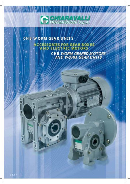
CHB WORM <strong>GEAR</strong> UNITS<br />
<strong>ACCESSORIES</strong> <strong>FOR</strong> <strong>GEAR</strong> <strong>BOXES</strong><br />
<strong>AND</strong> <strong>ELECTRIC</strong> MOTORS<br />
CHB WORM <strong>GEAR</strong>ED MOTORS<br />
<strong>AND</strong> WORM <strong>GEAR</strong> UNITS<br />
02.07
INDEX<br />
Introduction Page 1<br />
CHB 03-04-05 Worm geared motors and worm gear units Page 2<br />
CHB – CHB..P 03-04-05 – designation and order example Page 3<br />
CHB 03-04-05 Mounting positions Page 4<br />
CHB 03 Performance and dimensions with 4-pole motors Page 5<br />
CHB 04 Performance and dimensions with 4-pole motors Page 6<br />
CHB 05 Performance and dimensions with 4-pole motors Page 7<br />
CHB 06 Gear motors and worm gears Page 9<br />
CHB 06 – designation and order example Page 10<br />
CHB 06 Mounting positions Page 11<br />
CHB 06 Performance and dimensions with 4-pole motors Page 12<br />
CHBR – CHBRE Dimensions Page 13<br />
CHTPC Worm gear with pre-stage modules Page 14<br />
CHTPC / CHB Performance with 4-pole motors Page 15<br />
CHB / CHB Combined worm gears Page 16<br />
CHB / CHB Execution Page 17<br />
CHB / CHB Performance and dimensions with 4-pole motors Page 18<br />
Torque arm kit – Single and double output shaft Page 19<br />
Cover Page 20<br />
Technical data for CHT electric motors Page 21<br />
Forced ventilation kit Page 22<br />
Use and maintenance instructions Page 23<br />
General sales conditions Page 24<br />
N.B. CHIARAVALLI TRASMISSIONI SPA reserves the right to modify this catalogue without compensation of any kind for damages deriving from any errors that may be present in it.
INTRODUCTION<br />
The new CHB worm gearboxes of Chiaravalli Trasmissioni SPA have been produced to satisfy the market that require a product in<br />
dimensions and construction without changing the existing drawings and to guarantee non stop of their spare parts.<br />
Chiaravalli designed this new product by improving and introducing better technical modifications to offer easier application of the groups<br />
to the different assembling configurations so that by offering a better service in flexibility and delivery time.<br />
Starting from these considerations , we have a gearbox with a motor mounting flange that is separable from the housing which incorporate<br />
the oil seal; in this way we avoid any risk of damaging the oil seal in case of replacement of the input flange and the O-Ring can be<br />
eliminated.<br />
All the aside covers, swinging and with feet, have O-Rings instead of traditional flat gaskets. The sizes 03-04-05 allow the rotation of the<br />
feet without disassembling them; furthermore the versions with swinging aside covers allow the lateral flanges to be fitted on both sides<br />
with simple fixing screws.<br />
The worm screw has a ZI involute profile: with this worm-wheel coupling we shall get a better performance with a temperature reduction.<br />
The gearboxes and motors are painted with RAL 9022 aluminium colour epoxy powder to protect the parts from oxidation and against<br />
micro—blowholes that can come during the pressure of die-castings.<br />
The CHTPC pre-stage gears (already present in the catalogue of CHM) can also be mounted with this range, obtaining a gear ratio up to<br />
1:300. For bigger reductions is possible to have two gears together using an appropriate kit.<br />
LUBRICATION<br />
All of the groups are supplied with a synthetic lubricant and the maintenance is free and can be mounted in any position. The types of<br />
lubricants are described in the table here below.<br />
Lubricant Ambient ISO AGIP SHELL IP<br />
°C Ambient -25°C/+50°C VG 320 Telium VSF 320 Tivela oil S 320 Telium VSF<br />
QUANTITY OF OIL IN LITRES<br />
CHB 03 04 05 06<br />
0.035 0.055 0.090 0.38<br />
MOTOR MOUNTING FLANGES<br />
Gears supplied with mounting flanges must be assembled with motors whose shaft and flange tolerances correspond to a “normal” class<br />
of quality in order to avoid vibration and forcing of the input bearing. Motors supplied by Chiaravalli guarantee this requirement fulfilled.<br />
For ease of consultation, the correspondence of the size of the B5 and B14 motor with the sizes of the shaft and the motor connection<br />
flange are shown in the following table.<br />
Remember that, as the motor connection flanges are separate from the body it is also possible to have a shaft / flange combination that<br />
does not correspond to the table, e.g. 19/140, thereby offering adaptability for other non-unified models such as the brushless or direct<br />
current types.<br />
MMF 056 063 071 080 090<br />
B5 9/120 11/140 14/160 19/200 24/200<br />
B14 9/80 11/90 14/105 19/120 24/140<br />
FEET ROTATION<br />
Gears with feet can be rotated into the N and V positions by simply unscrewing the fixing screws. We recommend that some sealant is<br />
applied to the 4 screws close to the worm screw, as the holes are through holes.<br />
1
CHB 03-04-05 <strong>GEAR</strong>ED MOTORS <strong>AND</strong> WORM <strong>GEAR</strong> UNITS<br />
CHB...<br />
CHB...P<br />
CHBE...<br />
CHBE...P<br />
CHBR...<br />
CHBR...P<br />
CHBRE...<br />
CHBRE...P<br />
2
DESIGNATION CHB..P 03-04-05<br />
TYPE (1) SIZE VERSION FLANGE POS. (2) i MMF MOUNT. POS.<br />
CHB 03 F 1 7 63B5 UNIVERSAL<br />
CHB..P N 2 10 63B14<br />
CHBR V 15 56B5<br />
CHBR..P 20 56B14<br />
CHBE 30<br />
CHBE..P 40<br />
CHBRE 60<br />
CHBRE..P 70<br />
TYPE (1) SIZE VERSION FLANGE POS. (2) i MMF MOUNT. POS.<br />
CHB 04 F 1 7 71B5 UNIVERSAL<br />
CHB..P FA 2 10 71B14<br />
CHBR N 14 63B5<br />
CHBR..P V 20 63B14<br />
CHBE 28<br />
CHBE..P 35<br />
CHBRE 46<br />
CHBRE..P 60<br />
70<br />
100<br />
TYPE (1) SIZE VERSION FLANGE POS. (2) i MMF MOUNT. POS.<br />
CHB 05 F 1 7 80B5 UNIVERSAL<br />
CHB..P FA 2 10 80B14<br />
CHBR N 14 71B5<br />
CHBR..P V 18 71B14<br />
CHBE 24 63B5<br />
CHBE..P 28 63B14<br />
CHBRE 36<br />
CHBRE..P 45<br />
60<br />
70<br />
80<br />
100<br />
EXAMPLE ORDER<br />
CHB 04P FA 2 35 63 B14<br />
CHB 04 10 71 B5<br />
If the motor is also required, please specify:<br />
Size<br />
es. 63 C4<br />
Power es. Kw 0.22<br />
Poles es. 4<br />
Voltage es. V230/400<br />
Frequency es. 50 Hz<br />
Flange<br />
es. B14<br />
1) see page 2<br />
2) see page 4<br />
3
CHB 03-04-05 MOUNTING POSITION<br />
B3<br />
B6<br />
V5<br />
1<br />
1<br />
1<br />
B7<br />
B8<br />
V6<br />
3<br />
1<br />
1<br />
F1<br />
F2<br />
1<br />
B3<br />
4<br />
2<br />
POSITION OF TERMINAL BOX<br />
N.B. The position of the terminal box always refers to the B3 position.<br />
3<br />
4
CHB 03 PER<strong>FOR</strong>MANCE WITH 4-POLE MOTORS – 1400 REVS. INPUT<br />
TYPE i=ratio n2 r/min Kw=P1 Nm=T2 f.s. Possible types of motor connections<br />
CHB 03<br />
7 200 0.22 8 1.8 63/56 B5/B14<br />
10 140 0.22 11 1.4 63/56 B5/B14<br />
15 93 0.22 16 1.0 63/56 B5/B14<br />
20 70 0.22 20 0.9 63/56 B5/B14<br />
30 47 0.18 22 0.8 63/56 B5/B14<br />
40 35 0.12 18 1.0 63/56 B5/B14<br />
60 23 0.09 18 1.0 63/56 B5/B14<br />
70 20 0.09 15 0.9 56 B5/B14<br />
CHB 03 DIMENSIONS<br />
16<br />
55<br />
16<br />
52 46<br />
63<br />
52 46<br />
30<br />
55<br />
105<br />
ø 50 h8<br />
81.5<br />
30<br />
M6<br />
50<br />
40<br />
66<br />
81<br />
8<br />
6.5<br />
50<br />
1.5<br />
30<br />
65<br />
80<br />
V<br />
16<br />
55<br />
16<br />
30<br />
F1<br />
52 46<br />
5<br />
4<br />
55<br />
ø 80<br />
ø 50 H8<br />
30<br />
50<br />
52<br />
66<br />
81<br />
6.5<br />
50<br />
50.5<br />
68<br />
7<br />
80<br />
N<br />
55<br />
16 16<br />
52 46<br />
55<br />
30<br />
97.3<br />
66<br />
81<br />
6.5<br />
50<br />
80<br />
5
CHB 04 PER<strong>FOR</strong>MANCE WITH 4-POLE MOTORS – 1400 REVS. INPUT<br />
TYPE i=ratio n2 r/min Kw=P1 Nm=T2 f.s. Possible types of motor connections<br />
7 200 0.55* 22 1.4 71/63 B5/B14<br />
10 140 0.55* 30 1.0 71/63 B5/B14<br />
14 100 0.37 29 1.0 71/63 B5/B14<br />
CHB 04<br />
* motors 71 gr.<br />
20 70 0.37 38 1.0 71/63 B5/B14<br />
28 50 0.37 40 0.9 71/63 B5/B14<br />
35 40 0.25 41 0.9 71/63 B5/B14<br />
46 30 0.18 37 1.0 63 B5/B14<br />
60 23 0.18 44 0.9 63 B5/B14<br />
70 20 0.12 33 0.9 63 B5/B14<br />
100 14 0.12 30 0.9 63 B5/B14<br />
CHB 04 DIMENSIONS<br />
64<br />
24.5 24.5<br />
65 54<br />
74<br />
72<br />
81<br />
98<br />
10<br />
64<br />
24.5 24.5<br />
90<br />
44,6<br />
72<br />
65<br />
81<br />
98<br />
64<br />
8,5<br />
52<br />
90<br />
24.5 24.5<br />
65 54<br />
44,6<br />
123,7<br />
80<br />
44,6<br />
143,1<br />
8,5<br />
52<br />
2<br />
35<br />
110<br />
50<br />
h8<br />
760 H8<br />
11<br />
65 54<br />
9<br />
65 54<br />
60,5<br />
9<br />
7<br />
ø 110<br />
ø 60 H8<br />
44,6<br />
71,1<br />
44,6<br />
71,1<br />
44,6<br />
71,1<br />
M6<br />
52,2<br />
65<br />
V<br />
F1<br />
87<br />
ø 8,5<br />
N<br />
FA1<br />
65 54<br />
72<br />
8,5<br />
81<br />
98<br />
52<br />
90<br />
90<br />
87<br />
ø 8,5<br />
6
CHB 05 PER<strong>FOR</strong>MANCE WITH 4-POLE MOTORS – 1400 REVS. INPUT<br />
TYPE i=ratio n2 r/min Kw=P1 Nm=T2 f.s. Possible types of motor connections<br />
7 200 1.1* 40 1.4 80/71 B5/B14<br />
10 140 1.1* 49 1.2 80/71 B5/B14<br />
14 100 0.75 57 1.1 80/71 B5/B14<br />
18 18 78 0.55 52 1.1 80/71 B5/B14<br />
CHB 05<br />
* Motors 80 gr.<br />
24 58 0.55 67 0.9 80/71 B5/B14<br />
28 50 0.55 73 1.0 80/71 B5/B14<br />
36 39 0.37 61 1.1 71 B5/B14<br />
45 31 0.37 65 0.9 71 B5/B14<br />
60 23 0.25 60 1.0 71/63 B5/B14<br />
70 20 0.22 55 0.9 63 B5/B14<br />
80 17 0.18 54 1.0 63 B5/B14<br />
100 14 0.18 50 0.9 63 B5/B14<br />
CHB 05 DIMENSIONS<br />
82<br />
22 22<br />
70<br />
63<br />
82<br />
70<br />
63<br />
49,5<br />
82<br />
10<br />
49,5<br />
162,25<br />
80,25<br />
107<br />
ø 68 h8<br />
49,5<br />
M6<br />
80,25<br />
55<br />
98,5<br />
8,5<br />
63<br />
2.5<br />
37<br />
94<br />
124<br />
109,5<br />
V<br />
82<br />
22 22<br />
49,5<br />
F1<br />
10<br />
70<br />
63<br />
82<br />
ø 125<br />
ø 70 H8<br />
70<br />
98,5<br />
124<br />
8,5<br />
63<br />
109,5<br />
12<br />
85,5<br />
90<br />
N<br />
82<br />
22 22<br />
70<br />
63<br />
FA1<br />
10<br />
70<br />
63<br />
82<br />
49.5<br />
137,3<br />
ø 125<br />
ø 70 H8<br />
49,5<br />
80,25<br />
98,5<br />
8,5<br />
63<br />
12<br />
90<br />
7<br />
124<br />
109,5<br />
115
CHB 06 <strong>GEAR</strong>ED MOTORS <strong>AND</strong> WORM <strong>GEAR</strong> UNITS<br />
CHB 06<br />
CHBE 06<br />
CHBR 06<br />
CHBRE 06<br />
9
DESIGNATION CHB 06<br />
TYPE (1) SIZE VERSION FLANGE POS. (2) i MMF MOUNT. POS.<br />
CHB 06 FC 1 7 90B5 UNIVERSAL<br />
CHBR F 2 10 90B14<br />
CHBE (3) 12 80B5<br />
CHBRE 15 80B14<br />
19 71B5<br />
24 71B14<br />
30<br />
38<br />
45<br />
64<br />
80<br />
100<br />
EXAMPLE ORDER<br />
CHB 06 FA 1 19 90 B5<br />
If the motor is also required, please specify:<br />
Size<br />
es. 90 L4<br />
Power es. Kw 1.5<br />
Poles es. 4<br />
Voltage es. V230/400<br />
Frequency es. 50 Hz<br />
Flange<br />
es. B5<br />
1) see page 9<br />
2) see page 11<br />
3) lack of instructions indicates that the gear is not equipped with an output flange<br />
10
CHB 06 MOUNTING POSITION<br />
B3<br />
B6<br />
V5<br />
1<br />
1<br />
1<br />
B7<br />
B8<br />
V6<br />
3<br />
1<br />
1<br />
F1<br />
F2<br />
1<br />
B3<br />
11 5<br />
4<br />
3<br />
2<br />
POSITION OF TERMINAL BOX<br />
N.B. The position of the terminal box always refers to the B3 position.
CHB 06 PER<strong>FOR</strong>MANCE WITH 4-POLE MOTORS – 1400 REVS. INPUT<br />
TYPE i=ratio n2 r/min Kw=P1 Nm=T2 f.s. Possible types of motor connections<br />
7 200 1.85 75 1.5 90/80 B5/B14<br />
10 140 1.85 105 1.3 90/80 B5/B14<br />
12 117 1.85 129 1.1 90/80 B5/B14<br />
18 15 93 1.85 146 1.0 90/80 B5/B14<br />
CHB 06<br />
19 74 1.50 150 1.0 90/80 B5/B14<br />
24 58 1.10 138 1.1 90/80 B5/B14<br />
30 47 1.10 155 1.0 90/80 B5/B14<br />
38 37 0.75 133 1.1 90/80 B5/B14<br />
45 31 0.75 152 0.9 80/71 B5/B14<br />
64 22 0.37 101 1.2 80/71 B5/B14<br />
80 17 0.37 112 1.0 71 B5/B14<br />
100 14 0.37 110 1.0 71 B5/B14<br />
CHB 06 DIMENSIONS<br />
72.5 101<br />
120<br />
102<br />
51<br />
Ø 90<br />
22.5°<br />
M8x14<br />
8<br />
182.5<br />
72.5<br />
102 37.5<br />
ø 75 h8<br />
ø 75 h8<br />
102<br />
105<br />
145<br />
ø 9<br />
52<br />
76<br />
94<br />
3 53 53<br />
3<br />
72.5<br />
101<br />
CHB06F1<br />
76<br />
CHB06F2<br />
ø150<br />
ø115 h8<br />
ø180<br />
45°<br />
4-ø11<br />
78<br />
116<br />
5<br />
11<br />
72.5<br />
101<br />
76<br />
CHB06FC 1 CHB06FC 2<br />
45°<br />
ø150<br />
ø115 h8<br />
ø180<br />
4-ø11<br />
78<br />
86<br />
5<br />
11<br />
12
I<br />
CHBR – CHBRE – DIMENSIONS<br />
CHBR 03 - 04 - 05 CHBR 06<br />
f<br />
A<br />
B<br />
f<br />
A<br />
B<br />
CHBRE 03 - 04 - 05 CHBRE 06<br />
OUTPUT SHAFT DIMENSIONS<br />
b<br />
D<br />
t<br />
d<br />
I H<br />
f<br />
A<br />
B<br />
C<br />
A<br />
d<br />
d<br />
I H<br />
f<br />
A<br />
B<br />
C<br />
A<br />
d<br />
I H<br />
H<br />
R<br />
TYPE A B C D(H7) d(h6) f H I R b t<br />
CHBR 03 20 50 / 14 9 / 55 30 55 5 16.3<br />
CHBR 04 30 54 / 18 11 / 72 44.6 64 6 20.8<br />
CHBR 05 40 65 / 25 16 M6 85 49.5 82 8 28.3<br />
CHBR 06 40 110.5 / 25 18 M6 72.5 62.17 120 8 28.3<br />
CHBRE 03 20 50 50 14 9 / 55 30 55 5 16.3<br />
CHBRE 04 30 54 56 18 11 / 72 44.6 64 6 20.8<br />
CHBRE 05 40 65 65 25 16 M6 82 49.5 82 8 28.3<br />
CHBRE 06 40 110.5 74 25 18 M6 72.5 62.17 120 8 28.3<br />
13
CHTPC WORM <strong>GEAR</strong> WITH PRE-STAGE MODULE<br />
Z<br />
Z<br />
Z1<br />
E<br />
D<br />
F<br />
A<br />
Z<br />
Z1<br />
CHTPC 63 11/140 11/105<br />
CHTPC 71 14/160 14/120<br />
C<br />
B<br />
PINION ASSEMBLY INSTRUCTIONS<br />
1) Assemble the spacer A (if necessary heat between 80° and 100° C) onto the driving shaft and block it with Loctite 638<br />
for coaxial blockings<br />
2) Insert the key B included in the kit<br />
3) Assemble the pinion E (if necessary heat between 80° and 100° C) onto the driving shaft<br />
4) Fix the washer F using the screw C<br />
5) Assemble the oil seal D in the direction shown in the drawing<br />
6) Insert the motor with the pinion, taking care not to damage the oil seal<br />
Note: CHTPC pre-stage modul doesn’t allow radial loads.<br />
DESIGNATION CHTPC / CHB - CHB..P<br />
CHTPC / CHBE - CHB..P<br />
TYPE SIZE i = MMF<br />
CHTPC 63 3 63B5<br />
71 3 71B5<br />
EXAMPLE ORDER<br />
CHTPC 71 CHB 05 i= 108(3x36) MMF 71<br />
If the motor is also required, please specify:<br />
Size<br />
es. 71 B4<br />
Power es. Kw 0.37<br />
Poles es. 4<br />
Voltage es. V230/400<br />
Frequency es. 50 Hz<br />
14
CHTPC / CHB PER<strong>FOR</strong>MANCE WITH 4-POLE MOTORS – 1400 REVS. INPUT<br />
TYPE i=ratio n2 r/min Kw=P1 Nm=T2<br />
CHTPC63<br />
CHB 04<br />
105 13.3 0.12 42<br />
138 10.1 0.12 42<br />
180 7.8 0.12 46<br />
210 6.7 0.12 40<br />
300 4.7 0.12 36<br />
TYPE i=ratio n2 r/min Kw=P1 Nm=T2<br />
CHTPC63<br />
CHB 05<br />
108 12.9 0.18 72<br />
135 10.4 0.18 85<br />
180 10.4 0.18 85<br />
210 6.7 0.12 67<br />
240 5.8 0.12 58<br />
300 4.7 0.12 56<br />
TYPE i=ratio n2 r/min Kw=P1 Nm=T2<br />
CHTPC71<br />
CHB 05<br />
84 16.7 0.25 8<br />
108 12.9 0.25 90<br />
135 10.4 0.25 90<br />
TYPE i=ratio n2 r/min Kw=P1 Nm=T2<br />
CHTPC71<br />
CHB 06<br />
114 12.3 0.37 170<br />
135 10.4 0.37 176<br />
192 7.3 0.25 149<br />
240 5.8 0.25 130<br />
300 4.7 0.25 120<br />
DIMENSIONS CHTPC/CHB<br />
CHTPC.. / CHB 06<br />
CHTPC.. / CHB 03 - 04 - 05<br />
R1<br />
R1<br />
I2<br />
I2<br />
For other dimensions see pages 6 - 7 and 12 of the catalogue.<br />
CHTPC - CHB R1 I2<br />
63 + 04 110 40<br />
63 + 05 115 40<br />
71 + 05 123 50<br />
71 + 06 154 50<br />
The choice of power installed is tied to the unification of the motors, therefore it is sometimes in exuberance compared to the gear;<br />
always verify the maximum torque indicated when making the selection and if in doubt please contact our technical office.<br />
15
CHB/CHB COMBINED WORM <strong>GEAR</strong>S<br />
DESIGNATION CHB(R)/CHB – CHB(R)/CHB..P<br />
TYPE SIZE VERSION FLANGE POS. (1) i EXEC. MMF<br />
CHB/CHB 03/04 F 1 245 OAD 56B5<br />
CHB/CHB..P FA 2 350 OAS 56B14<br />
CHBR/CHB (2) 420 OBD<br />
CHBR/CHB..P 560 OBS<br />
700 VAD<br />
840 VAS<br />
1120 VBD<br />
1680 VBS<br />
2100<br />
TYPE SIZE VERSION FLANGE POS. (1) i EXEC. MMF<br />
CHB/CHB 03/05 F 1 240 OAD 63B5<br />
CHB/CHB..P FA 2 315 OAS 63B14<br />
CHBR/CHB (2) 420 OBD 56B5<br />
CHBR/CHB..P 540 OBS 56B14<br />
720 VAD<br />
900 VAS<br />
1120 VBD<br />
1440 VBS<br />
2160<br />
2700<br />
TYPE SIZE VERSION FLANGE POS. (1) i EXEC. MMF<br />
CHB/CHB 03/06 FC 1 240 OAD 63B5<br />
CHB/CHB..P F 2 315 OAS 63B14<br />
CHBR/CHB (3) 450 OBD 56B5<br />
CHBR/CHB..P 570 OBS 56B14<br />
720 VAD<br />
900 VAS<br />
1120 VBD<br />
1440 VBS<br />
2280<br />
2700<br />
For the executions see the table with drawings on page 17, if not specified OBS would be supplied.<br />
EXAMPLE ORDER<br />
CHB / CHB 03/05P FA 2 315 OBS 56B14<br />
If the motor is also required, please specify:<br />
Size<br />
es. 56 C4<br />
Power es. Kw 0.09<br />
Poles es. 4<br />
Voltage es. V230/400<br />
Frequency es. 50 Hz<br />
Flange<br />
es. B14<br />
1. see page 4 and 11<br />
2. lack of instructions indicates that the gear is not equipped with an output flange. In this case the group can be fixed on feet CHB/CHB or be swinging<br />
CHB/CHB..P<br />
3. lack of instructions indicates that the gear is not equipped with an output flange.<br />
16
EXECUTION<br />
OAD<br />
OAS<br />
3<br />
3<br />
OBD<br />
3<br />
OBS<br />
3<br />
VAD<br />
VAS<br />
1<br />
1<br />
VBS<br />
VBD<br />
1<br />
1<br />
The execution determines the mounting position of the first gear in relation to the<br />
second gear. If not otherwise specified at the time of order, the group will be supplied<br />
in the OBS execution. The placing position refers to the second gear.<br />
17
CHB / CHB PER<strong>FOR</strong>MANCE WITH 4-POLE MOTORS – 1400 REVS. INPUT<br />
TYPE i=ratio n2 r/min Kw=P1 Nm=T2<br />
CHB<br />
03/04<br />
245 5.7 0.09 58<br />
350 4.0 0.09* 58<br />
420 3.3 0.09* 58<br />
560 2.5 0.09* 58<br />
700 2.0 0.09* 58<br />
840 1.7 0.09* 58<br />
1120 1.3 0.09* 58<br />
1680 0.8 0.09* 58<br />
2100 0.7 0.09* 58<br />
TYPE i=ratio n2 r/min Kw=P1 Nm=T2<br />
240 5.8 0.12 77<br />
315 4.4 0.12 90<br />
420 3.3 0.09 90<br />
540 2.6 0.09 90<br />
720 1.9 0.09* 90<br />
900 1.6 0.09* 90<br />
1120 1.3 0.09* 90<br />
1440 0.9 0.09* 90<br />
2160 0.6 0.09* 90<br />
2700 0.5 0.09* 90<br />
CHB<br />
03/05<br />
TYPE i=ratio n2 r/min Kw=P1 Nm=T2<br />
240 5.8 0.22 160<br />
315 4.4 0.22 180<br />
450 3.1 0.18 200<br />
570 2.5 0.12 180<br />
720 1.9 0.12 200<br />
900 1.6 0.12 200<br />
1200 1.2 0.12 200<br />
1520 0.9 0.09* 200<br />
2280 0.6 0.09* 200<br />
2700 0.5 0.09* 200<br />
CHB<br />
03/06<br />
* The powers marked with an asterisk are higher than those<br />
that the gear allows, therefore the applicative choice must be<br />
made in accordance with the torque and not with the power.<br />
DIMENSIONS OF CHB/CHB COMBINED <strong>GEAR</strong>S<br />
CHB 03 / CHB 04 - 05 CHB 03 / CHB 06<br />
Y<br />
Y<br />
Y<br />
CHB 03 / 04 120.5<br />
CHB 03 / 04 120.5<br />
CHB 03 / 05 125.5<br />
CHB 03 / 05 125.5<br />
CHB 03 / 06 165<br />
For other dimensions see pages 5-6-7 and 12 of the catalogue.<br />
The gear ratios are those most frequently requested. It is possible to obtain multiple combinations using the various ratios of the<br />
two single gears.<br />
18
TORQUE ARM<br />
TIPO I A B Ø P Ø P Ø d H øE S<br />
CHB 03 100 40 157.5 50 65 7 14 8 4<br />
CHB 04 100 40 157.5 50 65 7 14 8 4<br />
CHB 05 100 55 172.5 68 94 7 14 8 4<br />
CHB 06 150 52.5 232.5 75 90 9 20 10 6<br />
ø d<br />
22°30’<br />
ø d<br />
øC øP<br />
øC øP<br />
A<br />
B<br />
I<br />
øE<br />
A<br />
B<br />
I<br />
øE<br />
H<br />
S<br />
03-04-05 06<br />
H<br />
S<br />
* Without anti vibrationbush<br />
The anchoring point of the torque<br />
arm is equipped with a vibration<br />
resistant bushing.<br />
SINGLE OUTPUT SHAFT KIT<br />
TYPE A Ø d B b t1 R L d2 ød1<br />
CHB 03 30 14 35 5 16 61 96 M5x13 14<br />
CHB 04 40 18 45 6 20.5 70 115 M6x16 18<br />
CHB 05 60 25 65 8 28 89 154 M8x20 25<br />
CHB 06 60 25 65 8 28 127 192 M8x20 25<br />
t 1<br />
d h6<br />
UNI 6604<br />
DIN 6885<br />
b<br />
d 2<br />
DIN 332<br />
R<br />
L<br />
A<br />
B<br />
d h6<br />
DOUBLE OUTPUT SHAFT KIT<br />
TYPE A Ø d B R b t1 L d2 ød1<br />
CHB 03 30 14 32.5 55 5 16 120 M5x13 14<br />
CHB 04 40 18 42.7 64 6 20.5 149.4 M6x16 18<br />
CHB 05 60 25 63.2 82 8 28 208.4 M8x20 25<br />
CHB 06 60 25 63.2 120 8 28 246.4 M8x20 25<br />
t 1<br />
d h6<br />
UNI 6604<br />
DIN 6885<br />
b<br />
d h6<br />
d 2<br />
DIN 332<br />
A<br />
B<br />
R<br />
L<br />
A<br />
B<br />
d h6<br />
19
COVER<br />
CHB 03 - 04 - 05 CHB 06<br />
C3<br />
C3<br />
TYPE<br />
C3<br />
03 37<br />
04 42<br />
05 55<br />
06 70<br />
REDUCTION BUSHINGS KIT<br />
SINGLE<br />
TYPE ø i/ø e L tongues Weight per kit<br />
kg<br />
CHT BRM-S 9/11 20 4/3 x 4 x 11 RB* 0.006<br />
CHT BRM-S 11/14 30 5/4 x 6 x 10 RB* 0.015<br />
CHT BRM-S 14/19 40 6 x 5 x 30 * 0.045<br />
CHT BRM-S 19/24 50 6 x 5.5 x 20 *<br />
8 x 5.5 x 40 *<br />
0.07<br />
CHT BRM-S 24/28 60 8 x 9 x 40 * 0.08<br />
CHT BRM-S 28/38 80 10 x 7 x 60 * 0.33<br />
CHT BRM-S 38/42 110 12/10 x 10 x 48 RB* 0.22<br />
DOUBLE<br />
TYPE ø i/ø e L tongues Weight per kit<br />
kg<br />
CHT BRM-D 11/19 40 6 x 6 x 30 * 0.06<br />
CHT BRM-D 14/24 50 8 x 7 x 40 A 0.12<br />
CHT BRM-D 19/28 60 8 x 7 x 50 A 0.16<br />
CHT BRM-D 24/38 80 10 x 8 x 60 A 0.44<br />
L<br />
L<br />
* to drawing<br />
Tongue acc. to UNI 6604 – DIN 6885<br />
Quenched<br />
ø e<br />
ø i<br />
ø i<br />
ø e<br />
20
TECHNICAL DATA <strong>FOR</strong> 4-POLE MOTORS<br />
THREE-PHASE <strong>ELECTRIC</strong> MOTORS<br />
(1400 RPM)<br />
TYPE POWER VOLTAGE CURRENT TORQUE EFFICIENCY FACTOR WEIGHT<br />
kW V 400 V N/m % COS. Ø Kg.<br />
CHT 56 B4 0.09 230/400 0.43 0.64 50 0.61 3.2<br />
CHT 63 A4 0.12 230/400 0.47 0.86 57 0.64 3.9<br />
CHT 63 B4 0.18 230/400 0.70 1.27 57 0.65 4.5<br />
CHT 63 C4 0.22 230/400 0.92 1.77 59 0.67 4.8<br />
CHT 71 A4 0.25 230/400 0.84 1.77 60 0.72 5.6<br />
CHT 71 B4 0.37 230/400 1.12 2.58 65 0.74 6.2<br />
CHT 71 C4 0.55 230/400 1.61 3.81 66 0.75 7.0<br />
CHT 80 A4 0.55 230/400 1.59 3.81 67 0.75 8.9<br />
CHT 80 B4 0.75 230/400 1.94 5.20 72 0.78 10.0<br />
CHT 80 D4 1.10 230/400 2.67 7.60 76.2 0.78 11.0<br />
CHT 90 S4 1.10 230/400 2.64 7.50 76.2 0.79 12.1<br />
CHT 90 L4 1.50 230/400 3.46 10.20 78.5 0.80 14.3<br />
CHT 90 LL4 1.85 230/400 4.30 9.24 79 0.78 16.0<br />
CHT 100 L A4 2.20 230/400 4.86 14.80 79.6 0.80 21.0<br />
CHT 100 L B4 3.00 230/400 6.50 20.20 80.5 0.81 24.7<br />
CHT 112 M4 4.00 230/400 8.26 26.70 83.6 0.84 30.1<br />
CHT 132 S4 5.50 230/400 11.00 36.22 87 0.85 44.0<br />
CHT 132 M4 7.50 230/400 14.64 49.40 88 0.86 52.0<br />
G<br />
b<br />
d<br />
X<br />
S<br />
L<br />
v<br />
C<br />
G<br />
b<br />
d<br />
X<br />
S<br />
L<br />
v<br />
M<br />
B<br />
F<br />
M<br />
C<br />
B<br />
B5<br />
H<br />
I<br />
F<br />
B14<br />
H<br />
I<br />
SIZES <strong>AND</strong> DIMENSIONS<br />
Type Mounting dimensions (mm) Dimensions<br />
B5<br />
B14<br />
d H b G I M F X V S I M F X V S B C L<br />
56 9 20 3 10.2 98 80 120 0 7 3.0 65 50 80 0 M5 2.5 120 100 195<br />
63 11 23 4 12.5 115 95 140 0 10 3.0 75 60 90 0 M5 2.5 130 110 215<br />
71 14 30 5 16 130 110 160 0 10 3.5 85 70 105 0 M6 2.5 145 117 255<br />
80 19 40 6 21.5 165 130 200 0 12 3.5 100 80 120 0 M6 3.0 165 137 290<br />
90S 24 50 8 27 165 130 200 0 12 3.5 115 95 140 0 M8 3.0 185 145 310<br />
90L/90LL 24 50 8 27 165 130 200 0 12 3.5 115 95 140 0 M8 3.0 185 145 335<br />
100L 28 60 8 31 215 180 250 0 15 4.0 130 110 160 0 M8 3.5 205 152 386<br />
112M 28 60 8 31 215 150 250 0 15 4.0 130 110 160 0 M8 3.5 230 180 395<br />
132S 38 80 10 41 265 230 300 0 15 4.0 165 130 200 0 M10 4.0 270 195 436<br />
132M 38 80 10 41 265 230 300 0 15 4.0 165 130 200 0 M10 4.0 270 195 475<br />
21<br />
- Motors with cage rotor, closed with external surface ventilation.<br />
- Design, construction and testing in conformity with the standards IEC<br />
2-3, international standards IEC 34-1 and the main foreign standards.<br />
- Power-sizes in accordance with the standards IEC 72, national standards<br />
UNEL-MEC.<br />
- Insulation class F<br />
- Protection IP55<br />
- S1 Continuous service<br />
- Efficiency class EFF2<br />
- European Directive ROHS 2002/95/CE<br />
- NSK or SKF Bearings<br />
- Phase separators<br />
- 2-pole and 6-pole motors available<br />
- Kit of feet available<br />
- Forced ventilation kit available for single-phase<br />
and three-phase models
<strong>FOR</strong>CED VENTILATION KIT * SINGLE-PHASE MODELS<br />
L x L<br />
F<br />
C<br />
G<br />
A interno<br />
B<br />
E<br />
D<br />
SINGLE-PHASE DIMENSIONS WITH IP55 TERMINAL BOX<br />
SIZE VOLTAGE HZ NOM. ABSORB. CURRENT AIR FLOW<br />
SPEED MIN/1 WATT M.A. M 3/H<br />
GR.63 230 50 / 60 2750 15 / 14 120 / 100 180<br />
GR.71 230 50 / 60 2750 15 / 14 120 / 100 180<br />
GR.80 230 50 / 60 2750 15 / 14 120 / 100 180<br />
GR.90 230 50 / 60 2900 42 / 36 190 / 180 340<br />
GR.100 230 50 / 60 2900 42 / 36 190 / 180 340<br />
GR.112 230 50 / 60 2900 42 / 36 190 / 180 340<br />
GR.132 230 50 / 60 2900 42 / 36 190 / 180 340<br />
SIZE<br />
GR.63<br />
GR.71<br />
GR.80<br />
GR.90<br />
GR.100<br />
GR.112<br />
GR.132<br />
COD. IP55<br />
AS063230<br />
AS071230<br />
AS080230<br />
AS090230<br />
AS100230<br />
AS112230<br />
AS132230<br />
A B C D E F G L x L<br />
121 123 102 58 6 50 104 75<br />
136 138 120 70 6 50 111 75<br />
153 155 130 80 6 55 125 100<br />
172 176 145 75 6 60 135 100<br />
195 197 150 85 8 60 150 100<br />
218 220 160 100 10 60 160 100<br />
255 257 180 120 10 65 175 100<br />
* <strong>FOR</strong>CED VENTILATION KIT THREE-PHASE MODELS<br />
AVAILABLE ON REQUEST<br />
22
Use and maintenance instructions<br />
INSTALLATION<br />
- The data shown on the identification name plate must correspond to the gear<br />
ordered<br />
- All the gears are supplied complete with permanent synthetic oil in a<br />
quantity that is sufficient for any assembly position<br />
- The gear must be fixed on a flat surface that is sufficiently rigid in order to avoid<br />
any vibration<br />
- The gear and the axis of the machine to be driven must be perfectly aligned<br />
- In the event that knocks, overloading or blockage of the machine are foreseen,<br />
the client must install a limiting device, joints, overload cut-out etc.<br />
- Coupling with pinions, joints, pulleys and other parts must be done after the<br />
parts have been cleaned and knocks should be avoided whilst assembling as<br />
they could damage the bearings and other internal parts<br />
- In the event that the motor is supplied by the client, he must check that the<br />
flange and shaft tolerances correspond to a “normal” class; our motors satisfy<br />
this requirement<br />
- Check that the fixing screws for the gear and the related accessories are correctly<br />
tightened<br />
- Take suitable measures to protect the groups from any aggressive atmospheric<br />
agents<br />
- Where foreseen, protect rotating parts from any possible contact with the<br />
operators<br />
- If the gears are painted, protect the oil seals and the machined surfaces<br />
- All of the gears are painted RAL 9022 grey<br />
OPERATION <strong>AND</strong> RUNNING-IN<br />
- To obtain the best performance the gears must first be run-in by gradually<br />
increasing the power in the first few hours of operation, in this phase an increase<br />
in temperature is considered normal<br />
- In the event of defective operation, noise, oil leakage, etc. stop the gear immediately<br />
and, when possible, remove the cause. Alternatively, send the piece to our factory<br />
to be controlled.<br />
MAINTENANCE<br />
- The worm gears from size 03 to size 06 and the pre-stage modules are lubricated<br />
with permanent synthetic oil and therefore do not require any maintenance<br />
WAREHOUSE STORAGE<br />
- If the warehouse storage will be for a long time, more than 3 months, the shafts<br />
and machined surfaces should be protected using antioxidants and the oil seals<br />
should be greased<br />
H<strong>AND</strong>LING<br />
- Care must be taken not to damage the oil seals and the machined surfaces<br />
when handling the groups<br />
DISPOSAL OF PACKAGING<br />
- The packaging in which our gears are delivered should be sent to specialised<br />
companies for recycling if possible.<br />
23
GENERAL SALES CONDITIONS<br />
1) ORDERS – Orders for special and standard material must always refer to<br />
offers made by CHIARAVALLI Trasmissioni SpA.<br />
The orders are binding for the client. Once work has commenced no cancellations<br />
or order reductions will be accepted unless the client reimburses the costs of<br />
the material and the work carried out up to the moment in which the order was<br />
suspended. The quantity despatched can vary by ± 5% compared to the quantity<br />
ordered.<br />
2) PRICES – The prices are those in force at the date of order. All prices are for<br />
goods delivered ex-works Premezzo, packing excluded. If there should be any<br />
increase in production and material costs over the duration of the supply,<br />
CHIARAVALLI Trasmissioni SpA reserves the right to adapt the prices accordingly,<br />
even for orders in course.<br />
3) TERMS OF DELIVERY – Only the terms of delivery indicated by CHIARAVALLI<br />
Trasmissioni SpA are to be considered valid. However, they must only be considered<br />
as indicative. In the event of difficulty in the procurement of materials, strikes or<br />
in any event in all cases of force majeure, the terms of delivery will be automatically<br />
extended without CHIARAVALLI Trasmissioni SpA having to pay any reimbursement<br />
for damages. The client is obligated to collect special material ordered when ready.<br />
4) DELIVERIES – Deliveries are the responsibility of the purchaser and are carried<br />
out at his own risk and peril. Any claims for shortages must be presented within<br />
8 days of receipt of the goods. If it is agreed that the cost of transport is to be<br />
paid, even if only in part, by CHIARAVALLI Trasmissioni SpA, the latter reserves<br />
the right to choose the most economical means of transport.<br />
5) PACKING – Packing will be invoiced at cost.<br />
6) RETURNS – No returns for any reason will be accepted unless previously<br />
authorised and with packing, any customs clearance and the return paid for by<br />
the purchaser. To cover warehouse and administrative expenses a debit note will<br />
be issued for approx. 15% of the value of the goods returned.<br />
7) WARRANTY – CHIARAVALLI Trasmissioni SpA promises to repair or substitute<br />
free of charge any parts that they recognise as being defective. The questioned<br />
goods must be returned to the factory of CHIARAVALLI Trasmissioni SpA, free<br />
of all expenses. The warranty will be considered cancelled in the event that the<br />
parts returned as defective have been repaired or tampered with. The repair of<br />
defective parts carried out by the purchaser will only be accepted after authorisation<br />
from CHIARAVALLI Trasmissioni SpA and after their approval of the cost estimate.<br />
CHIARAVALLI Trasmissioni SpA does not accept responsibility or pay any<br />
reimbursement for damages that occur during the use of their products, even if<br />
defective.<br />
8) RESPONSIBILITY – CHIARAVALLI Trasmissioni SpA does not accept responsibility<br />
or pay any reimbursement for damages that occur during the use of their products,<br />
even if defective. CHIARAVALLI Trasmissioni SpA declines all responsibility in the<br />
execution of parts to a client’s design under any patents.<br />
9) PAYMENTS – Only payments carried out in the manner and terms agreed<br />
will be considered valid. Once the due date of payment has passed, CHIARAVALLI<br />
Trasmissioni SpA will calculate the interest on delayed payment at a rate that is<br />
3% higher than the legal one, retaining the right to demand payment. In the event<br />
of delayed or missing payment by the purchaser, the company CHIARAVALLI<br />
Trasmissioni SpA reserves the right to suspend deliveries of the orders in course<br />
or to demand advance payment without having to pay any reimbursement or<br />
compensation to the purchaser. Any dispute regarding materials in manufacture<br />
or already possessed by the purchaser does not free the latter from the commitment<br />
of making the payment by the agreed date and for the whole amount of the<br />
invoice without making any deductions.<br />
10) OWNERSHIP –All of the goods despatched remain the property of<br />
CHIARAVALLI Trasmissioni SpA until the invoice is fully paid.<br />
11) COMPETENT COURT – Any controversy concerning business relations with<br />
CHIARAVALLI Trasmissioni SpA will be dealt with under the jurisdiction of the<br />
Court of Busto Arsizio.<br />
24
02/07<br />
dialogacrea.com<br />
FILIALI ITALIANE - DEPOSITI<br />
via per Cedrate s/n<br />
21044 Cavaria con Premezzo - VARESE<br />
Tel. 0331 214511 - Fax 0331 215916<br />
via 1° Maggio, 10<br />
40011 BOLOGNA / Anzola dell'Emilia<br />
Tel. 051 735290 - Fax 051 735366<br />
via E. Cantoni, 3 - 20156 MILANO<br />
Tel. 02 33400947 - Fax 02 33400949<br />
via Portogallo, 11 int. 51 - 35127 PADOVA<br />
Tel. 049 8705205 - Fax 049 8705237<br />
via G. B. Lulli, 61 H - 10148 TORINO<br />
Tel. 011 2267146 - Fax 011 2266925<br />
FILIALI ESTERE<br />
CHIARAVALLI FRANCE SARL<br />
2, bis rue de Paris - F-77230 Villeneuve S/Dammartin FRANCE<br />
Ph. 0033 1 60946666 - Fax 0033 1 60946660<br />
www.chiaravalli.fr - e-mail: info@chiaravalli.fr<br />
CHIARAVALLI ESPAÑA SL<br />
C/. Industria S/N - E - 08592 Sant Marti de Centelles Barcelona ESPAÑA<br />
Ph. 0034 93 8440099 - Fax 0034 93 8442193<br />
e-mail: chiaravall@grupobbva.net<br />
CHIARAVALLI CZ s.r.o.<br />
Brnenská, 43 - 59101 Zd'ár nad Sázavou CZECH REPUBLIC<br />
Ph. 00420 566 686161 - Fax 00420 566 686171<br />
www.chiaravalli.cz - e-mail: info@chiaravall.cz<br />
CHIARAVALLI POLSKA Sp. z o.o.<br />
Ul. Polna, 133 - 87-100 Torun<br />
Ph. 0048 56 6233000 - Fax 0048 56 6238246<br />
www.chiaravalli.pl - e-mail: info@chiaravalli.pl<br />
Via T. Minniti, 560<br />
21044 Cavaria con Premezzo (VA) - Italy<br />
Tel. +39.0331.214.511<br />
Fax +39.0331.219.430 735.067 - 735.090<br />
www.chiaravalli.com<br />
e-mail: chiaravalli@chiaravalli.it


