PLATINUM DDL
PLATINUM® DDL PLATINUM® DDL
PLATINUM® DDL PLATINUM® DDL
- No tags were found...

Create successful ePaper yourself
Turn your PDF publications into a flip-book with our unique Google optimized e-Paper software.
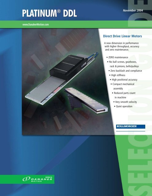
<strong>PLATINUM</strong> ® <strong>DDL</strong><br />
November 2004<br />
www.DanaherMotion.com<br />
Direct Drive Linear Motors<br />
A new dimension in performance<br />
with higher throughput, accuracy<br />
and zero maintenance.<br />
• ZERO maintenance<br />
• No ball screws, gearboxes,<br />
rack & pinions, belts/pulleys<br />
• Zero backlash and compliance<br />
• High stiffness<br />
• High positional accuracy<br />
• Compact mechanical<br />
assembly<br />
• Reduced parts count<br />
in machine<br />
• Very smooth velocity<br />
• Quiet operation
Introduction<br />
Kollmorgen<br />
<strong>PLATINUM</strong> ® <strong>DDL</strong><br />
The Direct Drive Linear (<strong>DDL</strong>) Story<br />
What is direct drive? Very simply it is the direct coupling of a linear<br />
motor (such as the Kollmorgen <strong>PLATINUM</strong>® <strong>DDL</strong>) to the driven<br />
load. With this configuration, all mechanical transmissions, such as<br />
ball/lead screws, rack & pinions, belts/pulleys, and gearboxes are<br />
eliminated. This in turn eliminates backlash and compliance and<br />
other problems associated with these mechanical transmissions.<br />
The <strong>DDL</strong> Benefits:<br />
• ZERO maintenance<br />
• No ball screws, gearboxes, rack & pinions, belts/pulleys<br />
• Zero backlash and compliance<br />
• High stiffness<br />
• High positional accuracy<br />
• Compact mechanical assembly<br />
• Reduced parts count in machine<br />
• Very smooth velocity<br />
• Quiet operation<br />
The <strong>PLATINUM</strong> <strong>DDL</strong> linear motor line provides a new dimension in<br />
performance with higher throughput, accuracy, and zero maintenance.<br />
Kollmorgen <strong>PLATINUM</strong> <strong>DDL</strong><br />
Kollmorgen supplied its first linear motors in the late 1970’s for use<br />
in precision X-Y tables and coating systems. These were brush DC<br />
motors using the Kollmorgen patented push-through commutator<br />
bar method. This led to development in the early 1980’s of the<br />
brushless versions of the linear motor which were used in film<br />
processing applications where smooth, high stiffness, linear motion<br />
was required. During the past 10 years, advances in permanent<br />
magnet material, power semiconductors, and microprocessor<br />
technology have been the enablers for increased performance and<br />
lower costs for linear motors.<br />
These developments have been refined into the Kollmorgen<br />
<strong>PLATINUM</strong> <strong>DDL</strong> product line of easily applied, cost effective linear<br />
motor components. The product line consists of two fundamental<br />
constructions, Ironless and Ironcore. The Ironless motors have no<br />
attractive force between the frameless components and have Zero<br />
cogging for ultra smooth motion. The Ironcore motors provide the<br />
highest force per frame size. They feature a patented anti-cogging<br />
design which yields extremely smooth operation from these high<br />
force motors.<br />
Standard Features:<br />
Ironless:<br />
• Peak force 60 to 1600 N (13.6 to 360 lbf)<br />
• Continuous force 21 to 450 N (4.6 to 101 lbf)<br />
• Zero cogging<br />
• Zero attractive force<br />
• Smooth motion for speed as low as 1 micron/second<br />
(0.00004 in/sec)<br />
• Low mass coil assembly for high acceleration<br />
Ironcore:<br />
• Peak force IC series: 190 to 15625 N (43 to 3513 lbf)<br />
• Continuous force IC series: 73 to 12023 N (16 to 2703 lbf)<br />
• Peak force ICD series: 170 to 1130 N (38 to 254 lbf)<br />
• Continuous force ICD series: 57 to 315 N (13 to 71 lbf)<br />
• Patented anti-cogging technique for minimal cogging<br />
without magnet skewing<br />
• High motor constant (Km)<br />
• High force density<br />
• ICD Series Advantage:<br />
– Very low profile<br />
– Low attraction force<br />
– Suitable to replace many Ironless applications<br />
All Motors:<br />
• Zero contact, zero maintenance, brushless design<br />
• 3 phase sinusoidal commutation<br />
• Peak accelerations easily above 10 g’s<br />
• High position accuracy and resolution<br />
• Very low settling time<br />
• Low thermal losses<br />
• Modular magnet design<br />
Standard Options:<br />
• Hall effect feedback<br />
• Thermal protection<br />
– Thermistor<br />
– Thermostat (Ironcore)<br />
• Supplemental air or water cooling (Ironcore)<br />
• Cable options<br />
• Magnet way covers for easy cleaning (Ironcore)<br />
• FM approved, hazardous environment<br />
DANAHER MOTION is a registered trademark of Danaher Corporation. Danaher Motion makes every attempt to ensure accuracy and reliability of the specifications in this publication. Specifications are subject to change without notice. Danaher Motion provides this information "AS IS" and<br />
disclaims all warranties, express or implied, including, but not limited to, implied warranties of merchantability and fitness for a particular purpose. It is the responsibility of the product user to determine the suitability of this product for a specific application. ©2004 Danaher Motion.<br />
2<br />
Tel<br />
: 540 633•3400 Web site : www.DanaherMotion.com
<strong>PLATINUM</strong> ® <strong>DDL</strong><br />
Kollmorgen<br />
Introduction<br />
How to Use this Data Publication<br />
This data publication makes the selection of a high performance linear<br />
motor simple! It includes a wide variety of linear motor components<br />
and cables that will adapt to your application needs. The linear motor<br />
selection guide at the back of this book is organized to lead you to the<br />
right motor quickly. The magnet ways for the Ironless, ICD and Ironcore<br />
motors are presented at the end of their respective sections so you can<br />
match any coil with any length of magnet assembly. To complete your<br />
sizing, use the model number ordering sheet at the back of this<br />
publication to build your part number as you size the motor.<br />
Easy Selection process:<br />
1. Determine peak and continuous force required for<br />
your applications (see our applications section on pages<br />
60-64 or use MOTIONEERING®, Danaher Motion’s<br />
sizing and selection software)<br />
2. Use the motor selection guide on pages 65 and 66 of<br />
this Data Publication to choose your motor<br />
3. Refer to the appropriate pages in the data publication<br />
for technical details<br />
4. Build model number for ordering using page 67<br />
Kollmorgen <strong>PLATINUM</strong> <strong>DDL</strong> Motors are Manufactured under one or<br />
more of the following patents:<br />
4,369,383 4,644,199 4,749,921 5,910,691 5,411,808 5,519,266<br />
5,642,013 6,160,327 WO 96/15574 and others.<br />
Kollmorgen <strong>PLATINUM</strong> <strong>DDL</strong> motors have been reviewed, tested, and<br />
found to be in conformity to the following standards: EN 60034, EN<br />
60204-1, IEC 34-1. Product has been reviewed per EN 60950, EN<br />
60529, IEC 721-3, NEMA MG7, UL1004, UL547, and UL674.<br />
The Kollmorgen <strong>PLATINUM</strong> <strong>DDL</strong> motors comply with the Low Voltage<br />
Directive 73/23/EEC for installation in a machine. Safety depends<br />
upon installing and configuring Motor per the manufacturer’s<br />
recommendations. The machine in which this product is to be installed<br />
must conform to the provisions of EC directive 89/336/EEC. The<br />
installer is responsible for ensuring that the end product complies with<br />
all the relevant laws in the country where the equipment is installed.<br />
The Data Publication is organized in the<br />
following sections:<br />
Pages<br />
Linear Motor Technology 4-5<br />
Ironless technical data 6-14<br />
electrical/mechanical specifications<br />
mechanical outlines of coil assemblies<br />
Ironless magnet ways technical data 14-17<br />
mechanical outline of magnet ways<br />
typical installation of magnet assemblies<br />
ICD technical data 18-24<br />
electrical/mechanical specifications<br />
mechanical outlines of coil assemblies<br />
ICD magnet ways technical data 22-24<br />
mechanical outline of magnet ways<br />
typical installation of magnet assemblies<br />
Ironcore technical data (non-cooled) 25-39<br />
electrical/mechanical specifications<br />
mechanical outlines of coil assemblies<br />
Ironcore technical data (water cooled) 40-53<br />
electrical/mechanical specifications<br />
mechanical outlines of coil assemblies<br />
Ironcore magnet ways technical data 54-56<br />
mechanical outlines of magnet ways<br />
typical installation of multiple magnet ways<br />
High Flex Cable Sets and Ordering Information 57-58<br />
Motor Wiring and Phasing diagrams 59<br />
Application Sizing Information 60-64<br />
Linear Motor Selection Charts 65-66<br />
Model Numbering System for Coils, Hall Effects, 67<br />
Magnet Ways, and Ordering Information<br />
DANAHER MOTION is a registered trademark of Danaher Corporation. Danaher Motion makes every attempt to ensure accuracy and reliability of the specifications in this publication. Specifications are subject to change without notice. Danaher Motion provides this information "AS IS" and<br />
disclaims all warranties, express or implied, including, but not limited to, implied warranties of merchantability and fitness for a particular purpose. It is the responsibility of the product user to determine the suitability of this product for a specific application. ©2004 Danaher Motion.<br />
Tel : 540 633 • 3400 Web site : www.DanaherMotion.com 3
Introduction<br />
Kollmorgen<br />
<strong>PLATINUM</strong> ® <strong>DDL</strong><br />
What is a Linear Servomotor?<br />
The Kollmorgen <strong>PLATINUM</strong>® <strong>DDL</strong> Series motors are frameless<br />
permanent magnet, three phase brushless servomotors.<br />
Fundamentally, a linear motor is a rotary motor that is rolled out flat.<br />
Stator<br />
N<br />
Rotor<br />
Rotary Motor<br />
S<br />
Permanent<br />
Magnets<br />
Windings<br />
Air Gap<br />
Rotary Motor Rolled Out Flat<br />
Linear Motor<br />
Slider<br />
The two primary components of permanent magnet brushless rotary<br />
motors are the stator (primary coils) and the rotor (secondary or<br />
rotating magnets). In brushless linear motors the rotor is rolled out<br />
flat to become the magnet track (also called the magnet way). The<br />
primary coils of the rotary motor are rolled out flat to become the<br />
coil assembly (also sometimes called the slider). In most brushless<br />
linear motor applications it is typical for the magnet way to be<br />
stationary and the coil assembly to be in motion, because of the<br />
relative masses of the two components. But it is also perfectly<br />
acceptable and sometimes advantageous<br />
to reverse this arrangement. The basic<br />
electromagnetic operating principles are<br />
the same in either case and are identical<br />
to those of a rotary motor.<br />
Two types of linear motors are available,<br />
Ironcore and Ironless. Each one provides<br />
characteristics and features that are<br />
optimal depending upon the application.<br />
Ironcore motors have coils wound on<br />
silicon steel laminations, to maximize the<br />
generated force, with a single sided magnet way. Using a patented<br />
electromagnetic design, Kollmorgen <strong>PLATINUM</strong> <strong>DDL</strong> linear motors<br />
have the highest rated force per size, a high Km motor constant<br />
(equals low thermal losses), and low cogging forces without the<br />
need for skewing of the magnets. The high thrust forces possible<br />
with these motors make them ideal for accelerating and moving<br />
high masses, and maintaining stiffness during machining or process<br />
forces. Ironless motors have no iron, or slots for the coils to be<br />
Base<br />
wound on. Therefore, these motors have zero cogging, a very light<br />
mass, and absolutely no attractive forces between the coil assembly<br />
and the magnet way. These characteristics are ideal for applications<br />
requiring very low bearing friction, high acceleration of lighter<br />
loads, and for maximizing constant velocity, even at ultra low<br />
speeds. The modular magnet ways consists of a double row of<br />
magnets to maximize the generated thrust force and to provide<br />
a flux return path for the magnetic circuit.<br />
Feedback Types:<br />
All brushless motors require feedback for commutation. The<br />
conventional rotary motor typically utilizes a resolver mounted on<br />
the rear of the motor or Hall effect devices mounted integrally in the<br />
coil windings. For a linear motor, commutation feedback can also be<br />
accomplished with a variety of methods. Digital or linear Hall effect<br />
devices are available from Kollmorgen for the <strong>PLATINUM</strong> <strong>DDL</strong> series<br />
which allow the drive electronics to commutate the linear motors in<br />
a manner identical to rotary motors.<br />
For exceptionally smooth motion requirements, sinusoidal drive<br />
electronics such as the Kollmorgen ServoStar® series, using digital<br />
Hall effects, provide sinusoidal drive currents to the motor for the<br />
best constant force and velocity performance. As an alternative, it is<br />
typical for linear motor applications to<br />
have a linear encoder present in the<br />
system for position feedback. It is<br />
increasingly common today for drive<br />
amplifiers, such as the Kollmorgen<br />
ServoStar Digital amplifier, to derive the<br />
necessary commutation information<br />
directly from this linear encoder, either<br />
with or without supplemental digital<br />
Hall effect devices on startup. Other<br />
Ironless Motor<br />
types of feedback used on linear motor<br />
applications include linear Inductosyns,<br />
laser interferometers, and LVDT’s.<br />
Ironcore Motor<br />
DANAHER MOTION is a registered trademark of Danaher Corporation. Danaher Motion makes every attempt to ensure accuracy and reliability of the specifications in this publication. Specifications are subject to change without notice. Danaher Motion provides this information "AS IS" and<br />
disclaims all warranties, express or implied, including, but not limited to, implied warranties of merchantability and fitness for a particular purpose. It is the responsibility of the product user to determine the suitability of this product for a specific application. ©2004 Danaher Motion.<br />
4<br />
Tel<br />
: 540 633•3400 Web site : www.DanaherMotion.com
<strong>PLATINUM</strong> ® <strong>DDL</strong><br />
Kollmorgen<br />
Introduction<br />
Advantages of Linear motors:<br />
High Stiffness<br />
In a linear motor system the motor is connected directly to the<br />
moving load. Therefore, there is no backlash and practically no<br />
compliance between the motor and the load. When the motor moves<br />
the load moves instantly. Shown in the graph is a comparison<br />
showing the very high dynamic stiffness of a Kollmorgen ironcore<br />
linear motor vs. a typical ground ball screw.<br />
Stiffness in lbs./inch<br />
Ironcore model 22-100 Stiffness vs. Ballscrew<br />
100,000,000<br />
10,000,000<br />
1,000,000<br />
Ballscrew<br />
100,000<br />
1 10 100<br />
1000<br />
Region of Potential<br />
Resonances for<br />
Ballscrew<br />
Linear Motor<br />
Frequency in Hz<br />
Wide Speed Range<br />
Since the frameless parts of the linear motor are non-contact, and no<br />
limitations of a mechanical transmission are present, both very high<br />
speeds and very low speeds are easily obtainable. Speeds are truly<br />
not limited by the motor. Instead, by eliminating the mechanical<br />
transmission, speed becomes limited by other elements in the system<br />
such as the linear bearings, and the achievable bandwidth from any<br />
feedback devices. Application speeds of greater than 5 meters per<br />
second (200 in./sec.) or less than 1 micron per second (.00004<br />
in./sec.) are typically achievable. In comparison, mechanical<br />
transmissions such as ball screws are commonly limited to linear<br />
speeds of 0.5 to 0.7 meters per second (20-30 in./sec.) because of<br />
resonances and wear. In addition to a wide speed range, linear<br />
motors, both ironcore and ironless, have excellent constant velocity<br />
characteristics, typically better than ± 0.01% speed variation.<br />
High System Dynamics<br />
In addition to high speed capability, direct drive linear motors are<br />
capable of very high accelerations. Limited only by the system bearings,<br />
accelerations of 3 to 5g’s are quite typical for the larger motors and<br />
accelerations exceeding 10g’s are easily achievable for smaller motors.<br />
Smooth Operation and Positional Accuracy<br />
Both ironless and ironcore motors exhibit very smooth motion<br />
profiles due to the inherent motor design of the Kollmorgen<br />
<strong>PLATINUM</strong>® <strong>DDL</strong> series. Cogging, which is a component of force, is<br />
greatly reduced in the ironcore designs and is zero in the ironless<br />
designs. As a result, these direct drive linear motors provide very low<br />
force and velocity ripple for ultra smooth motion. Positioning<br />
accuracies are limited only by the feedback resolution, and sub-micron<br />
resolutions are commonly achievable.<br />
Unlimited Travel<br />
Kollmorgen Platinum <strong>DDL</strong> series magnet ways are made in 5 modular<br />
sections: 64mm, 128mm, 256mm, 512mm and 1024mm long. Each<br />
module can be added in unlimited numbers to any other module to<br />
allow for unlimited travel. Whether the travel required is 1 millimeter<br />
(0.04 inches) or 100 meters (330 feet), the <strong>PLATINUM</strong> <strong>DDL</strong> series can<br />
accommodate the need.<br />
No Wear or Maintenance<br />
Linear motors have few components, therefore the need for ball<br />
screw components such as nuts, bearing blocks, couplings, motor<br />
mounts and the need to maintain these components have been<br />
eliminated. Very long life and clean operation, with no lubrication or<br />
maintenance of these parts are the result.<br />
Integration of Components is Much Simpler<br />
Frameless linear motors require much fewer components than rotary<br />
motors with mechanical transmissions. A 0.8mm airgap (0.031 inches)<br />
for the ironcore design and 0.5mm airgap (0.020 inches) for the ironless<br />
design is the only alignment of the frameless linear motor components<br />
that is necessary. No critical alignments are required as with ball screws.<br />
Straightness of travel as provided by the system linear bearings is more<br />
than sufficient for the Kollmorgen linear motors.<br />
Typical Applications for Linear Motors Include:<br />
Machine Tool<br />
Drilling<br />
Milling<br />
Grinding<br />
Laser cutting<br />
Cam grinding<br />
Semiconductor<br />
Wafer handling process<br />
Wafer inspection<br />
Wafer slicing<br />
Tab bonding<br />
Wire bonding<br />
Ion implantation<br />
Lithography<br />
Textile<br />
Carpet tufting<br />
Measurement/Inspection<br />
Coordinate Measurement Machines<br />
Electronic Assembly<br />
Pick-and-place machines<br />
Component insertion<br />
Screen printers<br />
Adhesive dispensers<br />
PC board inspection, drilling<br />
Other applications include:<br />
Flight Simulators<br />
Acceleration sleds<br />
Catapult<br />
G-Force measurement<br />
DANAHER MOTION is a registered trademark of Danaher Corporation. Danaher Motion makes every attempt to ensure accuracy and reliability of the specifications in this publication. Specifications are subject to change without notice. Danaher Motion provides this information "AS IS" and<br />
disclaims all warranties, express or implied, including, but not limited to, implied warranties of merchantability and fitness for a particular purpose. It is the responsibility of the product user to determine the suitability of this product for a specific application. ©2004 Danaher Motion.<br />
Tel : 540 633 • 3400 Web site : www.DanaherMotion.com 5
Ironless Motors<br />
Kollmorgen<br />
<strong>PLATINUM</strong> ® <strong>DDL</strong><br />
06 Series Ironless - Non-cooled<br />
Rated Performance Symbol Units IL06-015 IL06-030 IL06-050 IL06-075 IL06-100<br />
Peak force Fp N 60 120 200 300 400<br />
lbf 13.6 27 45 68 90<br />
Continuous force @ Tmax Fc N 21 38 61 87 113<br />
see note ➀ lbf 4.6 9 14 19 25<br />
Motor constant @ 25°C Km N/ W 3.3 5.6 8.0 10.2 12.1<br />
Max. Cont. power dissipation Pc W 53 65 83 101 121<br />
Electrical Specifications<br />
Winding Code A1 A4 A1 A4 A1 A4 A1 A4 A1 A4<br />
Peak current Ip Arms 7.2 14.4 7.1 14.2 7.0 14.0 7.0 14.0 7.0 14.0<br />
Continuous Current @ Tmax Ic Arms 2.5 4.9 2.3 4.5 2.1 4.3 2.0 4.1 2.0 4.0<br />
Electrical resistance @ 25°C±10% Rm Ohms L-L 4.2 1.1 6.1 1.5 8.6 2.2 11.7 2.9 14.7 3.7<br />
Electrical inductance ±20% L mH L-L 0.50 0.13 1.30 0.33 3.00 0.75 5.00 1.25 7.00 1.75<br />
Back EMF constant @ 25°C±10% Ke Vpeak/m/s L-L 6.9 3.4 13.7 6.9 23.3 11.6 34.9 17.5 46.5 23.3<br />
Vpeak/in/sec L-L 0.17 0.09 0.35 0.17 0.59 0.30 0.89 0.44 1.18 0.59<br />
Force constant @25°C±10% Kf N/Arms 8.4 4.2 16.8 8.4 28.5 14.3 42.8 21.4 57.0 28.5<br />
lbf / Arms 1.9 0.9 3.8 1.9 6.4 3.2 9.6 4.8 12.8 6.4<br />
Mechanical Specifications<br />
Coil Assembly Mass ±15% Mc kg 0.23 0.27 0.32 0.38 0.45<br />
lbs 0.5 0.6 0.7 0.8 1.0<br />
Magnetic Way Type MW MW MW MW075 MW100<br />
015 015T 030 030L 050 050L<br />
Magnetic Way Mass ±15% Mw kg/m 5.1 4.2 9.4 7.3 12.2 10.2 18.9 27.3<br />
lb/in 0.28 0.23 0.51 0.40 0.68 0.56 1.05 1.51<br />
Figures of Merit & Additional Data<br />
Electrical time constant Te ms 0.12 0.21 0.35 0.43 0.48<br />
Max.Theoretical Acceleration Amax g’s 26.8 45.2 63.6 80.6 90.7<br />
Magnetic attraction Fa kN 0 0 0 0 0<br />
lbf 0 0 0 0 0<br />
Thermal Resistance<br />
- coils to external structure Rth °C/Watt 1.97 1.61 1.26 1.04 0.87<br />
Max. Allowable Coil Temp. Tmax °C 130 130 130 130 130<br />
Notes:<br />
➀ The motor continuous rated force is measured with the motor coils achieving the motor maximum allowable temperature Tmax. At this<br />
operating point the number of watts being dissipated by the coil assembly is equal to the maximum continuous power dissipation Pc.<br />
The heat load can be limited to a value below Pc by limiting the continuous rated output force of the motor to a value equal to:<br />
Fc = Km x Square Root (Pw); where Pw = the acceptable heat load, in watts, and must be a value below Pc.<br />
The RMS current needed to produce this force is simply Fc divided by the force constant Kf.<br />
➁ Alternate windings can be made available. Please consult the Danaher Motion Customer Assistance Center for design options.<br />
➂ Maximum Theoretical Acceleration is based on the motors peak force and the motor mass alone. Limitations due to such factors as the<br />
additional mass of the load, the bearing type and design, the shock rating of the feedback, the peak current available from the amplifier<br />
etc. must be considered to determine the achievable acceleration in each application.<br />
➃ Please see our Application Sizing pages in the back of this publication for more details on sizing and thermal considerations.<br />
DANAHER MOTION is a registered trademark of Danaher Corporation. Danaher Motion makes every attempt to ensure accuracy and reliability of the specifications in this publication. Specifications are subject to change without notice. Danaher Motion provides this information "AS IS" and<br />
disclaims all warranties, express or implied, including, but not limited to, implied warranties of merchantability and fitness for a particular purpose. It is the responsibility of the product user to determine the suitability of this product for a specific application. ©2004 Danaher Motion.<br />
6<br />
Tel<br />
: 540 633•3400 Web site : www.DanaherMotion.com
<strong>PLATINUM</strong> ® <strong>DDL</strong><br />
Kollmorgen<br />
Ironless Motors<br />
IL06-xxx<br />
FOR MOTOR CABLE<br />
AND HALL EFFECT MTG.<br />
SEE DRAWING BELOW<br />
24.4<br />
(.961)<br />
4.4<br />
(.173)<br />
10.8<br />
(.427)<br />
10.0<br />
(.394)<br />
17.0<br />
(.669)<br />
4.5<br />
(.176)<br />
15.4<br />
(.606)<br />
BOTH<br />
SIDES<br />
35.3<br />
(1.391)<br />
110.8 (4.362) MAX.<br />
40.0<br />
(1.575)<br />
40.0<br />
(1.575)<br />
2 PL.<br />
BOTH<br />
SIDES<br />
M5 X 0.8 X 5 DP.<br />
6 PL., 3 PER SIDE<br />
3.9<br />
(.152)<br />
M5 X 0.8 X 5 DP.<br />
4 PL.<br />
4.0<br />
(.157)<br />
"A"<br />
16.7<br />
(.657)<br />
"T"<br />
"B"<br />
Coil Width Typ. Assy. Width Typ. Assy. Height<br />
Motor Coil “A”<br />
+.7 (0.027)<br />
- .3 (0.012) “B”±.6 (.024) “T” ±.4 (.016)<br />
IL06-015 42.30 (1.665) 52.10 (2.051) 25.40 (1.000)<br />
IL06-015 T 42.30 (1.665) 52.10 (2.051) 21.80 (.858)<br />
IL06-030 57.30 (2.256) 78.50 (3.091) 25.40 (1.000)<br />
IL06-030 L 57.30 (2.256) 67.30 (2.650) 25.40 (1.000)<br />
IL06-050 77.30 (3.043) 98.50 (3.878) 25.40 (1.000)<br />
IL06-050 L 77.30 (3.043) 87.30 (3.437) 25.40 (1.000)<br />
IL06-075 102.30 (4.028) 123.50 (4.862) 30.00 (1.181)<br />
IL06-100 127.30 (5.012) 148.50 (5.846) 34.00 (1.339)<br />
COIL ASSEMBLY<br />
1.2 .05<br />
(.048 .002)<br />
CLEARANCE-<br />
SET UP DIM.<br />
COIL TO MAGNET AIRGAP<br />
0.74 REF TYP. FOR -015, -030, -050<br />
1.12 REF TYP. FOR -075 AND -100<br />
MAGNET WAY REF.<br />
Notes:<br />
➀ Dimensions in mm (inches)<br />
➁ Tolerances unless otherwise specified:<br />
no decimal place ± 0.8 (.03)<br />
X decimal place ± 0.1 (.004)<br />
XX decimal place ± 0.05 (.002)<br />
Termination and Hall Effect Options<br />
12.2 +_ .3<br />
(.480 +_ .012)<br />
4.0 +_ .3<br />
(.157 +_ .012)<br />
6.8 +_ .3<br />
(.268 +_ .012)<br />
HALL EFFECT CONNECTOR OPTION:<br />
POSITRONIC P/N: MD9M2000Z<br />
9 PIN, MALE<br />
MATING CONNECTOR REFERENCE:<br />
POSITRONIC P/N: MD9F2000X<br />
SEE WIRE TABLE, PAGE 59<br />
7.7 +_ .3<br />
(.303 +_ .012)<br />
MOTOR CABLE<br />
THERMAL<br />
MOTOR<br />
OPTIONAL HALL EFFECT<br />
AS SHOWN, MOUNTING HOLES<br />
M3 X 6.3 (.25) MIN. DP. 2 PL.<br />
HALL<br />
EFFECT<br />
PIN 1<br />
1<br />
2<br />
PIN 5<br />
PIN 1<br />
3<br />
2<br />
1<br />
PIN 1<br />
PIN 9<br />
STANDARD LENGTH,<br />
SEE TABLE<br />
#4-40 JACKNUT (2)<br />
(REMOVABLE FOR BULKHEAD MOUNTING)<br />
HALL EFFECT ASSEMBLY<br />
STANDARD LENGTH,<br />
SEE TABLE<br />
THERMAL PROTECTION CONNECTOR:<br />
2 PIN - MALE CONNECTOR<br />
FREE HANGING RECEPTACLE<br />
MOLEX P/N 43025-0200<br />
2 FEMALE TERMINALS<br />
MOLEX P/N 43030-0010<br />
COIL ASSEMBLY REF<br />
COIL ASSEMBLY REF<br />
21.0<br />
(.827)<br />
MAX.<br />
MATING CONNECTOR REFERENCE:<br />
MOLEX "MICRO-FIT 3.0"<br />
PLUG: 43020-0201<br />
MALE TERMINALS: 43031-0010<br />
SEE WIRE TABLE, PAGE 59<br />
MOTOR CONNECTOR:<br />
POSITRONIC P/N: CBD3W3M0000Z<br />
3 PIN MALE, SHELL SIZE 2<br />
MALE CONTACTS:<br />
POSITRONIC P/N: MS40--D<br />
3 REMOVABLE MALE<br />
CONTACTS, SIZE 8<br />
MATING CONNECTOR REFERENCE:<br />
POSITRONIC P/N: CBD3W3F0000X<br />
3 FEMALE SOCKETS, SOLDER TYPE,<br />
SIZE 8, POSITRONIC P/N: FS40--D<br />
SEE WIRE TABLE, PAGE 59<br />
HALL EFFECT MASS<br />
W/P* CONNECTOR: .05KG (.11 LB) MAX<br />
W/C* CABLE: .03KG (.06 LB) MAX<br />
Connector Option<br />
Connector Length<br />
P1 400 (16)<br />
P2 200 (8)<br />
P3 100 (4)<br />
Flying Lead Option<br />
Leads<br />
Length<br />
C1 400 (16)<br />
C2 200 (8)<br />
C3 100 (4)<br />
Note:<br />
Cables exiting motor and hall<br />
effects are not dynamic flex<br />
cables. For high life flex<br />
extension cables, see page 57<br />
DANAHER MOTION is a registered trademark of Danaher Corporation. Danaher Motion makes every attempt to ensure accuracy and reliability of the specifications in this publication. Specifications are subject to change without notice. Danaher Motion provides this information "AS IS" and<br />
disclaims all warranties, express or implied, including, but not limited to, implied warranties of merchantability and fitness for a particular purpose. It is the responsibility of the product user to determine the suitability of this product for a specific application. ©2004 Danaher Motion.<br />
Tel : 540 633 • 3400 Web site : www.DanaherMotion.com 7
Ironless Motors<br />
Kollmorgen<br />
<strong>PLATINUM</strong> ® <strong>DDL</strong><br />
12 Series Ironless - Non-cooled<br />
Rated Performance Symbol Units IL12-015 IL12-030 IL12-050 IL12-075 IL12-100<br />
Peak force Fp N 120 240 400 600 800<br />
lbf 27 54 90 135 180<br />
Continuous force @ Tmax Fc N 41 76 122 174 226<br />
see note ➀ lbf 9 17 28 39 51<br />
Motor constant @ 25°C Km N/ W 4.8 7.8 11.3 14.5 17.2<br />
Max. Cont. power dissipation Pc W 107 131 167 202 242<br />
Electrical Specifications<br />
Winding Code A1 A2 A4 A1 A2 A4 A1 A2 A4 A1 A2 A4 A2 A4<br />
Peak current Ip Arms 7.1 14.3 28.6 7.1 14.2 28.5 7.0 14.0 28.1 7.0 14.0 28.1 14.0 28.1<br />
Continuous Current @ Tmax Ic Arms 2.4 4.9 9.8 2.3 4.5 9.0 2.1 4.3 8.6 2.0 4.1 8.1 4.0 7.9<br />
Electrical resistance<br />
@ 25°C±10% Rm Ohms L-L 8.5 2.1 0.5 12.2 3.1 0.8 17.2 4.3 1.1 23.3 5.8 1.5 7.4 1.8<br />
Electrical inductance ±20% L mH L-L 1.00 0.25 0.06 2.60 0.65 0.16 6.00 1.50 0.38 10.00 2.50 0.63 3.50 0.88<br />
Back EMF constant Ke Vpeak/m/s L-L 13.7 6.9 3.4 27.5 13.8 6.9 46.5 23.3 11.6 69.8 34.9 17.5 46.5 23.3<br />
@ 25°C±10% Vpeak/in/sec L-L 0.35 0.17 0.09 0.70 0.35 0.17 1.18 0.59 0.30 1.77 0.89 0.44 1.18 0.59<br />
Force constant @ 25°C±10% Kf N/Arms 16.8 8.4 4.2 33.7 16.9 8.4 57.0 28.5 14.3 85.5 42.8 21.4 57.0 28.5<br />
lbf / Arms 3.8 1.9 0.9 7.6 3.8 1.9 12.8 6.4 3.2 19.2 9.6 4.8 12.8 6.4<br />
Mechanical Specifications<br />
Coil Assembly Mass ±15% Mc kg 0.35 0.42 0.52 0.65 0.77<br />
lbs 0.8 0.9 1.1 1.4 1.7<br />
Magnetic Way Type MW MW MW MW075 MW100<br />
015 015T 030 030L 050 050L<br />
Magnetic Way Mass ±15% Mw kg/m 5.1 4.2 9.4 7.3 12.2 10.2 18.9 27.3<br />
lbs/in 0.28 0.23 0.51 0.40 0.68 0.56 1.05 1.51<br />
Figures of Merit & Additional Data<br />
Electrical time constant Te ms 0.12 0.21 0.35 0.43 0.48<br />
Max.Theoretical Acceleration Amax g’s 35.0 58.2 78.4 94.1 106.0<br />
Magnetic attraction Fa kN 0 0 0 0 0<br />
lbf 0 0 0 0 0<br />
Thermal Resistance<br />
- coils to external structure Rth °C/Watt 0.984 0.804 0.629 0.519 0.433<br />
Max. Allowable Coil Temp. Tmax °C 130 130 130 130 130<br />
Notes:<br />
➀ The motor continuous rated force is measured with the motor coils achieving the motor maximum allowable temperature Tmax. At this<br />
operating point the number of watts being dissipated by the coil assembly is equal to the maximum continuous power dissipation Pc.<br />
The heat load can be limited to a value below Pc by limiting the continuous rated output force of the motor to a value equal to:<br />
Fc = Km x Square Root (Pw); where Pw = the acceptable heat load, in watts, and must be a value below Pc.<br />
The RMS current needed to produce this force is simply Fc divided by the force constant Kf.<br />
➁ Alternate windings can be made available. Please consult the Danaher Motion Customer Assistance Center for design options.<br />
➂ Maximum Theoretical Acceleration is based on the motors peak force and the motor mass alone. Limitations due to such factors as the<br />
additional mass of the load, the bearing type and design, the shock rating of the feedback, the peak current available from the amplifier<br />
etc. must be considered to determine the achievable acceleration in each application.<br />
➃ Please see our Application Sizing pages in the back of this publication for more details on sizing and thermal considerations.<br />
DANAHER MOTION is a registered trademark of Danaher Corporation. Danaher Motion makes every attempt to ensure accuracy and reliability of the specifications in this publication. Specifications are subject to change without notice. Danaher Motion provides this information "AS IS" and<br />
disclaims all warranties, express or implied, including, but not limited to, implied warranties of merchantability and fitness for a particular purpose. It is the responsibility of the product user to determine the suitability of this product for a specific application. ©2004 Danaher Motion.<br />
8<br />
Tel<br />
: 540 633•3400 Web site : www.DanaherMotion.com
<strong>PLATINUM</strong> ® <strong>DDL</strong><br />
Kollmorgen<br />
Ironless Motors<br />
IL12-xxx<br />
FOR MOTOR CABLE<br />
AND HALL EFFECT MTG.<br />
SEE DRAWING BELOW<br />
24.4<br />
(.961)<br />
4.4<br />
(.173)<br />
10.8<br />
(.427)<br />
10.0<br />
(.394)<br />
4.5<br />
(.176)<br />
17.0<br />
(.669)<br />
23.4<br />
(.921)<br />
BOTH<br />
SIDES<br />
43.4<br />
(1.709)<br />
40.0<br />
(1.575)<br />
4 PL.<br />
BOTH<br />
SIDES<br />
M5 X 0.8 X 5 DP. 8 PL.<br />
206.8<br />
(8.142)<br />
MAX.<br />
40.0<br />
(1.575)<br />
3 PL.<br />
M5 X 0.8 X 5 DP.<br />
10 PL., 5 PER SIDE<br />
16.7<br />
(.657)<br />
3.9<br />
(.152)<br />
4.0<br />
(.157)<br />
"A"<br />
Magnet Way<br />
REF.<br />
"B"<br />
"T"<br />
Coil Width Typ. Assy. Width Typ. Assy. Height<br />
Motor Coil “A”<br />
+.7 (0.027)<br />
- .3 (0.012) “B”±.6 (.024) “T” ±.4 (.016)<br />
IL06-015 42.30 (1.665) 52.10 (2.051) 25.40 (1.000)<br />
IL06-015 T 42.30 (1.665) 52.10 (2.051) 21.80 (.858)<br />
IL06-030 57.30 (2.256) 78.50 (3.091) 25.40 (1.000)<br />
IL06-030 L 57.30 (2.256) 67.30 (2.650) 25.40 (1.000)<br />
IL06-050 77.30 (3.043) 98.50 (3.878) 25.40 (1.000)<br />
IL06-050 L 77.30 (3.043) 87.30 (3.437) 25.40 (1.000)<br />
IL06-075 102.30 (4.028) 123.50 (4.862) 30.00 (1.181)<br />
IL06-100 127.30 (5.012) 148.50 (5.846) 34.00 (1.339)<br />
COIL ASSEMBLY<br />
1.2 ±.05<br />
(.048 ±.002)<br />
CLEARANCE-<br />
SET UP DIM.<br />
COIL TO MAGNET AIRGAP<br />
0.74 REF TYP. FOR -015, -030, -050<br />
1.12 REF TYP. FOR -075 AND -100<br />
Notes:<br />
➀ Dimensions in mm (inches)<br />
➁ Tolerances unless<br />
otherwise specified:<br />
no decimal place ± 0.8 (.03)<br />
X decimal place ± 0.1 (.004)<br />
XX decimal place ± 0.05 (.002)<br />
Termination and Hall Effect Options<br />
12.2 +_ .3<br />
(.480 +_ .012)<br />
4.0 +_ .3<br />
(.157 +_ .012)<br />
6.8 +_ .3<br />
(.268 +_ .012)<br />
HALL EFFECT CONNECTOR OPTION:<br />
POSITRONIC P/N: MD9M2000Z<br />
9 PIN, MALE<br />
MATING CONNECTOR REFERENCE:<br />
POSITRONIC P/N: MD9F2000X<br />
SEE WIRE TABLE, PAGE 59<br />
7.7 +_ .3<br />
(.303 +_ .012)<br />
MOTOR CABLE<br />
THERMAL<br />
MOTOR<br />
OPTIONAL HALL EFFECT<br />
AS SHOWN, MOUNTING HOLES<br />
M3 X 6.3 (.25) MIN. DP. 2 PL.<br />
HALL<br />
EFFECT<br />
PIN 1<br />
1<br />
2<br />
PIN 5<br />
PIN 1<br />
3<br />
2<br />
1<br />
PIN 1<br />
PIN 9<br />
STANDARD LENGTH,<br />
SEE TABLE<br />
#4-40 JACKNUT (2)<br />
(REMOVABLE FOR BULKHEAD MOUNTING)<br />
HALL EFFECT ASSEMBLY<br />
STANDARD LENGTH,<br />
SEE TABLE<br />
THERMAL PROTECTION CONNECTOR:<br />
2 PIN - MALE CONNECTOR<br />
FREE HANGING RECEPTACLE<br />
MOLEX P/N 43025-0200<br />
2 FEMALE TERMINALS<br />
MOLEX P/N 43030-0010<br />
COIL ASSEMBLY REF<br />
COIL ASSEMBLY REF<br />
21.0<br />
(.827)<br />
MAX.<br />
MATING CONNECTOR REFERENCE:<br />
MOLEX "MICRO-FIT 3.0"<br />
PLUG: 43020-0201<br />
MALE TERMINALS: 43031-0010<br />
SEE WIRE TABLE, PAGE 59<br />
MOTOR CONNECTOR:<br />
POSITRONIC P/N: CBD3W3M0000Z<br />
3 PIN MALE, SHELL SIZE 2<br />
MALE CONTACTS:<br />
POSITRONIC P/N: MS40--D<br />
3 REMOVABLE MALE<br />
CONTACTS, SIZE 8<br />
MATING CONNECTOR REFERENCE:<br />
POSITRONIC P/N: CBD3W3F0000X<br />
3 FEMALE SOCKETS, SOLDER TYPE,<br />
SIZE 8, POSITRONIC P/N: FS40--D<br />
SEE WIRE TABLE, PAGE 59<br />
HALL EFFECT MASS<br />
W/P* CONNECTOR: .05KG (.11 LB) MAX<br />
W/C* CABLE: .03KG (.06 LB) MAX<br />
Connector Option<br />
Connector Length<br />
P1 400 (16)<br />
P2 200 (8)<br />
P3 100 (4)<br />
Flying Lead Option<br />
Leads<br />
Length<br />
C1 400 (16)<br />
C2 200 (8)<br />
C3 100 (4)<br />
Note:<br />
Cables exiting motor and hall<br />
effects are not dynamic flex<br />
cables. For high life flex<br />
extension cables, see page 57<br />
DANAHER MOTION is a registered trademark of Danaher Corporation. Danaher Motion makes every attempt to ensure accuracy and reliability of the specifications in this publication. Specifications are subject to change without notice. Danaher Motion provides this information "AS IS" and<br />
disclaims all warranties, express or implied, including, but not limited to, implied warranties of merchantability and fitness for a particular purpose. It is the responsibility of the product user to determine the suitability of this product for a specific application. ©2004 Danaher Motion.<br />
Tel : 540 633 • 3400 Web site : www.DanaherMotion.com 9
Ironless Motors<br />
Kollmorgen<br />
<strong>PLATINUM</strong> ® <strong>DDL</strong><br />
18 Series Ironless - Non-cooled<br />
Rated Performance Symbol Units IL18-015 IL18-030 IL18-050<br />
Peak force Fp N 180 360 600<br />
lbf 40 81 135<br />
Continuous force @ Tmax Fc N 62 114 184<br />
see note ➀ lbf 14 26 41<br />
Motor constant @ 25°C Km N/ W 5.8 9.7 13.8<br />
Max. Cont. power dissipation Pc W 160 196 251<br />
Electrical Specifications<br />
Winding Code A1 A2 A3 A4 A1 A2 A3 A4 A1 A2 A3 A4<br />
Peak current Ip Arms 7.1 14.2 21.3 42.6 7.1 14.3 21.4 42.8 7.0 14.0 21.0 42.1<br />
Continuous Current @ Tmax Ic Arms 2.4 4.9 7.3 14.7 2.3 4.5 6.8 13.6 2.2 4.3 6.5 12.9<br />
Electrical resistance<br />
@ 25°C±10% Rm Ohms L-L 12.7 3.2 1.4 0.4 18.2 4.6 2.0 0.5 25.7 6.4 2.9 0.7<br />
Electrical inductance ±20% L mH L-L 1.50 0.38 0.17 0.04 3.80 0.95 0.42 0.11 9.00 2.25 1.00 0.25<br />
Back EMF constant Ke Vpeak/m/s L-L 20.7 10.3 6.9 3.4 41.2 20.6 13.7 6.9 69.8 34.9 23.3 11.6<br />
@ 25°C±10% Vpeak/in/sec L-L 0.52 0.26 0.17 0.09 1.05 0.52 0.35 0.17 1.77 0.89 0.59 0.30<br />
Force constant @ 25°C±10% Kf N/Arms 25.3 12.7 8.4 4.2 50.5 25.3 16.8 8.4 85.5 42.8 28.5 14.3<br />
lbf/Arms 5.7 2.8 1.9 0.9 11.4 5.7 3.8 1.9 19.2 9.6 6.4 3.2<br />
Mechanical Specifications<br />
Coil Assembly Mass ±15% Mc kg 0.46 0.57 0.72<br />
lbs 1.0 1.3 1.6<br />
Magnetic Way Type MW MW MW<br />
015 015T 030 030L 050 050L<br />
Magnetic Way Mass ±15% Mw kg/m 5.1 4.2 9.4 7.3 12.2 10.2<br />
lbs/in 0.28 0.23 0.51 0.40 0.68 0.56<br />
Figures of Merit & Additional Data<br />
Electrical time constant Te ms 0.12 0.21 0.35<br />
Max.Theoretical Acceleration Amax g’s 40.2 64.5 84.9<br />
Magnetic attraction Fa kN 0 0 0<br />
lbf 0 0 0<br />
Thermal Resistance<br />
- coils to external structure Rth °C/Watt 0.656 0.536 0.419<br />
Max. Allowable Coil Temp. Tmax °C 130 130 130<br />
Notes:<br />
➀ The motor continuous rated force is measured with the motor coils achieving the motor maximum allowable temperature Tmax. At this<br />
operating point the number of watts being dissipated by the coil assembly is equal to the maximum continuous power dissipation Pc.<br />
The heat load can be limited to a value below Pc by limiting the continuous rated output force of the motor to a value equal to:<br />
Fc = Km x Square Root (Pw); where Pw = the acceptable heat load, in watts, and must be a value below Pc.<br />
The RMS current needed to produce this force is simply Fc divided by the force constant Kf.<br />
➁ Alternate windings can be made available. Please consult the Danaher Motion Customer Assistance Center for design options.<br />
➂ Maximum Theoretical Acceleration is based on the motors peak force and the motor mass alone. Limitations due to such factors as the<br />
additional mass of the load, the bearing type and design, the shock rating of the feedback, the peak current available from the amplifier<br />
etc. must be considered to determine the achievable acceleration in each application.<br />
➃ Please see our Application Sizing pages in the back of this publication for more details on sizing and thermal considerations.<br />
DANAHER MOTION is a registered trademark of Danaher Corporation. Danaher Motion makes every attempt to ensure accuracy and reliability of the specifications in this publication. Specifications are subject to change without notice. Danaher Motion provides this information "AS IS" and<br />
disclaims all warranties, express or implied, including, but not limited to, implied warranties of merchantability and fitness for a particular purpose. It is the responsibility of the product user to determine the suitability of this product for a specific application. ©2004 Danaher Motion.<br />
10<br />
Tel<br />
: 540 633•3400 Web site : www.DanaherMotion.com
<strong>PLATINUM</strong> ® <strong>DDL</strong><br />
Kollmorgen<br />
Ironless Motors<br />
18 Series Ironless - Non-cooled<br />
Rated Performance Symbol Units IL18-075 IL18-100<br />
Peak force Fp N 900 1200<br />
lbf 202 270<br />
Continuous force @ Tmax Fc N 260 338<br />
see note ➀ lbf 59 76<br />
Motor constant @ 25°C Km N/ W 17.7 21.0<br />
Max. Cont. power dissipation Pc W 303 363<br />
Electrical Specifications<br />
Winding Code A1 A2 A3 A4 A1 A2 A3 A4<br />
Peak current Ip Arms 7.0 14.0 21.0 42.1 7.0 14.0 21.0 42.1<br />
Continuous Current @ Tmax Ic Arms 2.0 4.1 6.1 12.2 2.0 4.0 5.9 11.9<br />
Electrical resistance<br />
@ 25°C±10% Rm Ohms L-L 35.0 8.8 3.9 1.0 44.2 11.1 4.9 1.2<br />
Electrical inductance ±20% L mH L-L 15.0 3.75 1.67 0.42 21.0 5.25 2.33 0.58<br />
Back EMF constant Ke Vpeak/m/s L-L 105 52.4 34.9 17.5 140 69.9 46.6 23.3<br />
@ 25°C±10% Vpeak/in/sec L-L 2.66 1.33 0.89 0.44 3.55 1.77 1.18 0.59<br />
Force constant @ 25°C±10% Kf N/Arms 128 64.2 42.8 21.4 171 85.6 57.0 28.5<br />
lbf/Arms 28.8 14.4 9.6 4.8 38.5 19.2 12.8 6.4<br />
Mechanical Specifications<br />
Coil Assembly Mass ±15% Mc kg 0.91 1.10<br />
lbs 2.0 2.4<br />
Magnetic Way Type MW075 MW100<br />
Magnetic Way Mass ±15% Mw kg/m 18.9 27.3<br />
lbs/in 1.05 1.51<br />
Figures of Merit & Additional Data<br />
Electrical time constant Te ms 0.43 0.48<br />
Max.Theoretical Acceleration Amax g’s 101 111<br />
Magnetic attraction Fa kN 0 0<br />
lbf 0 0<br />
Thermal Resistance<br />
- coils to external structure Rth °C/Watt 0.35 0.29<br />
Max. Allowable Coil Temp. Tmax °C 130 130<br />
Notes:<br />
➀ The motor continuous rated force is measured with the motor coils achieving the motor maximum allowable temperature Tmax. At this<br />
operating point the number of watts being dissipated by the coil assembly is equal to the maximum continuous power dissipation Pc.<br />
The heat load can be limited to a value below Pc by limiting the continuous rated output force of the motor to a value equal to:<br />
Fc = Km x Square Root (Pw); where Pw = the acceptable heat load, in watts, and must be a value below Pc.<br />
The RMS current needed to produce this force is simply Fc divided by the force constant Kf.<br />
➁ Alternate windings can be made available. Please consult the Danaher Motion Customer Assistance Center for design options.<br />
➂ Maximum Theoretical Acceleration is based on the motors peak force and the motor mass alone. Limitations due to such factors as the<br />
additional mass of the load, the bearing type and design, the shock rating of the feedback, the peak current available from the amplifier<br />
etc. must be considered to determine the achievable acceleration in each application.<br />
➃ Please see our Application Sizing pages in the back of this publication for more details on sizing and thermal considerations.<br />
DANAHER MOTION is a registered trademark of Danaher Corporation. Danaher Motion makes every attempt to ensure accuracy and reliability of the specifications in this publication. Specifications are subject to change without notice. Danaher Motion provides this information "AS IS" and<br />
disclaims all warranties, express or implied, including, but not limited to, implied warranties of merchantability and fitness for a particular purpose. It is the responsibility of the product user to determine the suitability of this product for a specific application. ©2004 Danaher Motion.<br />
Tel : 540 633 • 3400 Web site : www.DanaherMotion.com 11
Ironless Motors<br />
Kollmorgen<br />
<strong>PLATINUM</strong> ® <strong>DDL</strong><br />
IL18-xxx<br />
FOR MOTOR CABLE<br />
AND HALL EFFECT MTG.<br />
SEE DRAWING BELOW<br />
24.4<br />
(.961)<br />
4.4<br />
(.173)<br />
10.8<br />
(.427)<br />
4.5<br />
(.176)<br />
31.4<br />
(1.236)<br />
BOTH<br />
SIDES<br />
17.0<br />
(.669)<br />
10.0<br />
(.394)<br />
51.4<br />
(2.023)<br />
302.8 (11.922) MAX.<br />
40.0<br />
(1.575)<br />
6 PL.<br />
BOTH<br />
SIDES<br />
40.0<br />
(1.575)<br />
5 PL.<br />
M5 X 0.8 X 5 DP.<br />
14 PL., 7 PER SIDE<br />
M5 X 0.8 X<br />
5 DP. 12 PL.<br />
4.0<br />
(.157)<br />
3.9<br />
(.152)<br />
"A"<br />
16.7<br />
(.657)<br />
"B"<br />
MAGNET WAY<br />
REF.<br />
Coil Width Typ. Assy. Width Typ. Assy. Height<br />
Motor Coil “A”<br />
+.7 (0.027)<br />
- .3 (0.012) “B”±.6 (.024) “T” ±.4 (.016)<br />
IL06-015 42.30 (1.665) 52.10 (2.051) 25.40 (1.000)<br />
IL06-015 T 42.30 (1.665) 52.10 (2.051) 21.80 (.858)<br />
IL06-030 57.30 (2.256) 78.50 (3.091) 25.40 (1.000)<br />
IL06-030 L 57.30 (2.256) 67.30 (2.650) 25.40 (1.000)<br />
IL06-050 77.30 (3.043) 98.50 (3.878) 25.40 (1.000)<br />
IL06-050 L 77.30 (3.043) 87.30 (3.437) 25.40 (1.000)<br />
IL06-075 102.30 (4.028) 123.50 (4.862) 30.00 (1.181)<br />
IL06-100 127.30 (5.012) 148.50 (5.846) 34.00 (1.339)<br />
COIL ASSEMBLY<br />
1.2 .05<br />
(.048 .002)<br />
CLEARANCE-<br />
SET UP DIM.<br />
COIL TO MAGNET AIRGAP<br />
0.74 REF TYP. FOR -015, -030, -050<br />
1.12 REF TYP. FOR -075 AND -100<br />
Notes:<br />
➀ Dimensions in mm (inches)<br />
➁ Tolerances unless otherwise<br />
specified:<br />
no decimal place ± 0.8 (.03)<br />
X decimal place ± 0.1 (.004)<br />
XX decimal place ± 0.05 (.002)<br />
"T"<br />
Termination and Hall Effect Options<br />
12.2 +_ .3<br />
(.480 +_ .012)<br />
4.0 +_ .3<br />
(.157 +_ .012)<br />
6.8 +_ .3<br />
(.268 +_ .012)<br />
HALL EFFECT CONNECTOR OPTION:<br />
POSITRONIC P/N: MD9M2000Z<br />
9 PIN, MALE<br />
MATING CONNECTOR REFERENCE:<br />
POSITRONIC P/N: MD9F2000X<br />
SEE WIRE TABLE, PAGE 59<br />
7.7 +_ .3<br />
(.303 +_ .012)<br />
MOTOR CABLE<br />
THERMAL<br />
MOTOR<br />
OPTIONAL HALL EFFECT<br />
AS SHOWN, MOUNTING HOLES<br />
M3 X 6.3 (.25) MIN. DP. 2 PL.<br />
HALL<br />
EFFECT<br />
PIN 1<br />
1<br />
2<br />
PIN 5<br />
PIN 1<br />
3<br />
2<br />
1<br />
PIN 1<br />
PIN 9<br />
STANDARD LENGTH,<br />
SEE TABLE<br />
#4-40 JACKNUT (2)<br />
(REMOVABLE FOR BULKHEAD MOUNTING)<br />
HALL EFFECT ASSEMBLY<br />
STANDARD LENGTH,<br />
SEE TABLE<br />
THERMAL PROTECTION CONNECTOR:<br />
2 PIN - MALE CONNECTOR<br />
FREE HANGING RECEPTACLE<br />
MOLEX P/N 43025-0200<br />
2 FEMALE TERMINALS<br />
MOLEX P/N 43030-0010<br />
COIL ASSEMBLY REF<br />
COIL ASSEMBLY REF<br />
21.0<br />
(.827)<br />
MAX.<br />
MATING CONNECTOR REFERENCE:<br />
MOLEX "MICRO-FIT 3.0"<br />
PLUG: 43020-0201<br />
MALE TERMINALS: 43031-0010<br />
SEE WIRE TABLE, PAGE 59<br />
MOTOR CONNECTOR:<br />
POSITRONIC P/N: CBD3W3M0000Z<br />
3 PIN MALE, SHELL SIZE 2<br />
MALE CONTACTS:<br />
POSITRONIC P/N: MS40--D<br />
3 REMOVABLE MALE<br />
CONTACTS, SIZE 8<br />
MATING CONNECTOR REFERENCE:<br />
POSITRONIC P/N: CBD3W3F0000X<br />
3 FEMALE SOCKETS, SOLDER TYPE,<br />
SIZE 8, POSITRONIC P/N: FS40--D<br />
SEE WIRE TABLE, PAGE 59<br />
HALL EFFECT MASS<br />
W/P* CONNECTOR: .05KG (.11 LB) MAX<br />
W/C* CABLE: .03KG (.06 LB) MAX<br />
Connector Option<br />
Connector Length<br />
P1 400 (16)<br />
P2 200 (8)<br />
P3 100 (4)<br />
Flying Lead Option<br />
Leads<br />
Length<br />
C1 400 (16)<br />
C2 200 (8)<br />
C3 100 (4)<br />
Note:<br />
Cables exiting motor and hall effects<br />
are not dynamic flex cables. For high<br />
life flex extension cables, see page 57<br />
DANAHER MOTION is a registered trademark of Danaher Corporation. Danaher Motion makes every attempt to ensure accuracy and reliability of the specifications in this publication. Specifications are subject to change without notice. Danaher Motion provides this information "AS IS" and<br />
disclaims all warranties, express or implied, including, but not limited to, implied warranties of merchantability and fitness for a particular purpose. It is the responsibility of the product user to determine the suitability of this product for a specific application. ©2004 Danaher Motion.<br />
12<br />
Tel<br />
: 540 633•3400 Web site : www.DanaherMotion.com
<strong>PLATINUM</strong> ® <strong>DDL</strong><br />
Kollmorgen<br />
Ironless Motors<br />
24 Series Ironless - Non-cooled<br />
Rated Performance Symbol Units IL24-015 IL24-030 IL24-050 IL24-075 IL24-100<br />
Peak force Fp N 240 480 800 1200 1600<br />
lbf 54 108 180 270 360<br />
Continuous force @ Tmax Fc N 83 152 245 348 450<br />
see note ➀ lbf 19 34 55 78 101<br />
Motor constant @ 25°C Km N/ W 6.7 11.2 15.9 20.6 24.4<br />
Max. Cont. power dissipation Pc W 213 261 333 405 484<br />
Electrical Specifications<br />
Winding Code A1 A2 A3 A1 A2 A3 A1 A2 A3 A1 A2 A3 A4 A1 A2 A3 A4<br />
Peak current Ip Arms 7.1 14.2 28.4 7.1 14.2 28.5 7.0 14.0 28.1 7.0 14.0 28.0 56.1 7.0 14.0 28.1 56.1<br />
Continuous Current @ Tmax Ic Arms 2.4 4.9 9.8 2.3 4.5 9.0 2.1 4.3 8.6 2.0 4.1 8.1 16.3 2.0 3.9 7.9 15.8<br />
Electrical resistance<br />
@ 25°C±10% Rm Ohms L-L 16.9 4.2 1.1 24.3 6.1 1.5 34.3 8.6 2.1 46.6 11.7 2.9 0.73 58.9 14.7 3.7 0.92<br />
Electrical inductance ±20% L mH L-L 2.00 0.50 0.13 5.10 1.28 0.32 12.0 3.00 0.75 20.0 5.00 1.25 0.31 28.0 7.00 1.75 0.44<br />
Back EMF constant Ke Vpeak/m/s L-L 27.5 13.8 6.9 55.0 27.5 13.8 93.1 46.5 23.3 140 69.9 34.9 17.5 186 93.1 46.6 23.3<br />
@ 25°C±10% Vpeak/in/sec L-L 0.70 0.35 0.17 1.40 0.70 0.35 2.36 1.18 0.59 3.55 1.77 0.89 0.44 4.73 2.37 1.18 0.59<br />
Force constant @ 25°C±10% Kf N/Arms 33.7 16.9 8.4 67.4 33.7 16.9 114 57.0 28.5 171 85.6 42.8 21.4 228 114 57.0 28.5<br />
lbf / Arms 7.6 3.8 1.9 15.2 7.6 3.8 25.6 12.8 6.4 38.5 19.2 9.6 4.8 51.3 25.6 12.8 6.4<br />
Mechanical Specifications<br />
Coil Assembly Mass ±15% Mc kg 0.57 0.72 0.92 1.17 1.42<br />
lbs 1.3 1.6 2.0 2.6 3.1<br />
Magnetic Way Type MW MW MW MW075 MW100<br />
015 015T 030 030L 050 050L<br />
Magnetic Way Mass ±15% Mw kg/m 5.1 4.2 9.4 7.3 12.2 10.2 18.9 27.3<br />
lbs/in 0.28 0.23 0.51 0.40 0.68 0.56 1.05 1.51<br />
Figures of Merit & Additional Data<br />
Electrical time constant Te ms 0.12 0.21 0.35 0.43 0.48<br />
Max.Theoretical Acceleration Amax g’s 42.9 68.0 88.7 105 115<br />
Magnetic attraction Fa kN 0 0 0 0 0<br />
lbf 0 0 0 0 0<br />
Thermal Resistance<br />
- coils to external structure Rth °C/Watt 0.49 0.40 0.32 0.26 0.22<br />
Max. Allowable Coil Temp. Tmax °C 130 130 130 130 130<br />
Notes:<br />
➀ The motor continuous rated force is measured with the motor coils achieving the motor maximum allowable temperature Tmax. At this<br />
operating point the number of watts being dissipated by the coil assembly is equal to the maximum continuous power dissipation Pc.<br />
The heat load can be limited to a value below Pc by limiting the continuous rated output force of the motor to a value equal to:<br />
Fc = Km x Square Root (Pw); where Pw = the acceptable heat load, in watts, and must be a value below Pc.<br />
The RMS current needed to produce this force is simply Fc divided by the force constant Kf.<br />
➁ Alternate windings can be made available. Please consult the Danaher Motion Customer Assistance Center for design options.<br />
➂ Maximum Theoretical Acceleration is based on the motors peak force and the motor mass alone. Limitations due to such factors as the<br />
additional mass of the load, the bearing type and design, the shock rating of the feedback, the peak current available from the amplifier<br />
etc. must be considered to determine the achievable acceleration in each application.<br />
➃ Please see our Application Sizing pages in the back of this publication for more details on sizing and thermal considerations.<br />
DANAHER MOTION is a registered trademark of Danaher Corporation. Danaher Motion makes every attempt to ensure accuracy and reliability of the specifications in this publication. Specifications are subject to change without notice. Danaher Motion provides this information "AS IS" and<br />
disclaims all warranties, express or implied, including, but not limited to, implied warranties of merchantability and fitness for a particular purpose. It is the responsibility of the product user to determine the suitability of this product for a specific application. ©2004 Danaher Motion.<br />
Tel : 540 633 • 3400 Web site : www.DanaherMotion.com 13
Ironless Motors/Magnet Ways<br />
Kollmorgen<br />
<strong>PLATINUM</strong> ® <strong>DDL</strong><br />
IL24-xxx<br />
FOR MOTOR CABLE<br />
AND HALL EFFECT MTG.<br />
SEE PAGE 12<br />
24.4<br />
(.961)<br />
4.4<br />
(.173)<br />
M5 X 0.8 X 5 DP.<br />
20 PL., 10 PER SIDE<br />
4.5<br />
(.176)<br />
10.8<br />
(.427)<br />
10.0<br />
(.394)<br />
17.0<br />
(.669)<br />
19.4<br />
(.764)<br />
39.4<br />
(1.551)<br />
BOTH<br />
SIDES<br />
40.0<br />
(1.575)<br />
9 PL.<br />
398.8 (15.701) MAX.<br />
M5 X 0.8 X 5 DP.<br />
18 PL., 9 PER SIDE<br />
40.0<br />
(1.575)<br />
8 PL.<br />
BOTH<br />
SIDES<br />
3.8<br />
(.152)<br />
16.7<br />
(.657)<br />
4.0<br />
(.157)<br />
"A"<br />
"B"<br />
Coil Width Typ. Assy. Width Typ. Assy. Height<br />
Motor Coil “A”<br />
+.7 (0.027)<br />
- .3 (0.012)<br />
“B”±.6 (.024) “T” ±.4 (.016)<br />
IL06-015 42.30 (1.665) 52.10 (2.051) 25.40 (1.000)<br />
IL06-015 T 42.30 (1.665) 52.10 (2.051) 21.80 (.858)<br />
IL06-030 57.30 (2.256) 78.50 (3.091) 25.40 (1.000)<br />
IL06-030 L 57.30 (2.256) 67.30 (2.650) 25.40 (1.000)<br />
IL06-050 77.30 (3.043) 98.50 (3.878) 25.40 (1.000)<br />
IL06-050 L 77.30 (3.043) 87.30 (3.437) 25.40 (1.000)<br />
IL06-075 102.30 (4.028) 123.50 (4.862) 30.00 (1.181)<br />
IL06-100 127.30 (5.012) 148.50 (5.846) 34.00 (1.339)<br />
MAGNET WAY REF.<br />
COIL ASSEMBLY<br />
1.2 .05<br />
(.048 .002)<br />
CLEARANCE-<br />
SET UP DIM.<br />
COIL TO MAGNET AIRGAP<br />
0.74 REF TYP. FOR -015, -030, -050<br />
1.12 REF TYP. FOR -075 AND -100<br />
Notes:<br />
➀ Dimensions in mm (inches)<br />
➁ Tolerances unless otherwise specified:<br />
no decimal place ± 0.8 (.03)<br />
X decimal place ± 0.1 (.004)<br />
XX decimal place ± 0.05 (.002)<br />
"T"<br />
Ironless Magnet Ways<br />
Magnet assemblies are modular and can be installed in multiples of same or<br />
alternate lengths (see page 17). Standard assembly lengths are shown below.<br />
MWxxx-0064<br />
63.3 ±.4<br />
(2.492 ±.016)<br />
MAGNETIC AIR GAP<br />
"W"<br />
22.94<br />
(.903)<br />
MAX.<br />
A<br />
M<br />
A<br />
SEE TABLE<br />
9.00 ±.13<br />
(.354 ±.005)<br />
18.00 ±.05<br />
(.709 ±.002)<br />
Ø5.160-5.185 (.203-.204) X 6 (.236) DP.<br />
2 PL. MARKED "A", BOTH SIDES<br />
CUSTOMER TOOLING HOLES,<br />
SEE PAGE 17<br />
"H"<br />
MAGNET<br />
LENGTH<br />
Magnet Size “H” “W” “Z”<br />
Magnet Way Ref. ± .08 (.003) ± .4 (.016) ± .4 (.016)<br />
MW015-0064 15mm 5.69 (.224) 33.80 (1.331) 25.40 (1.000)<br />
Ø5.160-5.185 (.203-.204) X 10 (.394) DP. 2 PL. MARKED "B",<br />
CUSTOMER TOOLING HOLES, SEE PAGE 17<br />
MW015T-0064 15mm 5.69 (.224) 33.80 (1.331) 21.80 (.858)<br />
MW030-0064 30mm 7.11 (.280) 60.20 (2.370) 25.40 (1.000)<br />
22.94<br />
MW030L-0064 30mm 5.69 (.224) 49.00 (1.929) 25.40 (1.000)<br />
(.903)<br />
MAX.<br />
MW050-0064 50mm 7.11 (.280) 80.20 (3.158) 25.40 (1.000)<br />
18.00 ±.05<br />
(.709 ±.002)<br />
MW050L-0064 50mm 5.69 (.224) 69.00 (2.716) 25.40 (1.000)<br />
MW075-0064 75mm 8.23 (.324) 105.20 (4.142) 30.00 (1.181)<br />
C L BB<br />
MW100-0064 100mm 8.23 (.324) 130.20 (5.126) 34.00 (1.339)<br />
"Z"<br />
7.00<br />
(.276)<br />
32.0<br />
(1.260)<br />
M5 X 0.8 X 8 DP. 2 PL.<br />
Notes:<br />
➀ Dimensions in mm (inches)<br />
➁ Tolerances unless otherwise specified:<br />
no decimal place ± 0.8 (.03)<br />
X decimal place ± 0.1 (.004)<br />
XX decimal place ± 0.05 (.002)<br />
32.0<br />
(1.260)<br />
REF.<br />
Hardware (Hex, Socket Head Cap)<br />
Hole Dia. C’bore Dia. C’bore Depth Bottom Mount<br />
Magnet Way ± .13 (.005) ± .13 (.005) ± .13 (.005) Metric Inch Thread Option<br />
MW015-0064 4.70 (.185) 7.80 (.307) 4.00 (.157) M4 #8 M4 X 0.7 X 6.0 DP.<br />
MW015T-0064 4.70 (.185) 7.80 (.307) 5.79 (.228) M4 #8 M4 X 0.7 X 6.0 DP.<br />
MW030-0064 5.70 (.224) 9.35 (.368) 5.79 (.228) M5 #10 M5 X 0.8 X 8.0 DP.<br />
MW030L-0064 4.70 (.185) 7.80 (.307) 5.79 (.228) M4 #8 M4 X 0.7 X 6.0 DP.<br />
MW050-0064 5.70 (.224) 9.35 (.368) 5.79 (.228) M5 #10 M5 X 0.8 X 8.0 DP.<br />
MW050L-0064 4.70 (.185) 7.80 (.307) 5.79 (.228) M4 #8 M4 X 0.7 X 6.0 DP.<br />
MW075-0064 5.70 (.224) 9.35 (.368) 7.95 (.313) M5 #10 M5 X 0.8 X 8.0 DP.<br />
MW100-0064 5.70 (.224) 9.35 (.368) 9.96 (.392) M5 #10 M5 X 0.8 X 8.0 DP.<br />
DANAHER MOTION is a registered trademark of Danaher Corporation. Danaher Motion makes every attempt to ensure accuracy and reliability of the specifications in this publication. Specifications are subject to change without notice. Danaher Motion provides this information "AS IS" and<br />
disclaims all warranties, express or implied, including, but not limited to, implied warranties of merchantability and fitness for a particular purpose. It is the responsibility of the product user to determine the suitability of this product for a specific application. ©2004 Danaher Motion.<br />
14<br />
Tel<br />
: 540 633•3400 Web site : www.DanaherMotion.com
<strong>PLATINUM</strong> ® <strong>DDL</strong><br />
Kollmorgen<br />
Ironless Magnet Ways<br />
MWxxx-0128<br />
127.3 ±.4<br />
(5.012 ±.016)<br />
MAGNETIC AIR GAP<br />
"W"<br />
22.94<br />
(.903)<br />
MAX.<br />
22.94<br />
(.903)<br />
MAX.<br />
9.00 ±.13<br />
(.354 ± .005)<br />
A<br />
M<br />
M<br />
A<br />
SEE TABLE<br />
Ø5.160-5.185 (.203-.204) X 6 (.236) DP.<br />
2 PL. MARKED "A", BOTH SIDES<br />
CUSTOMER TOOLING HOLES,<br />
SEE PAGE 17<br />
C L B<br />
B<br />
Hole Dia. C’bore Dia C’bore Depth<br />
Bottom Mount<br />
64.0<br />
Magnet Size “H” “W” “Z”<br />
(2.520)<br />
Magnet Way Ref. ± .08 (.003) ± .4 (.016) ± .4 (.016)<br />
82.00 ±.05<br />
MW015-0128 15mm 5.69 (.224) 33.80 (1.331) 25.40 (1.000)<br />
(3.228 ±.002)<br />
MW015T-0128 15mm 5.69 (.224) 33.80 (1.331) 21.80 (.858)<br />
MW030-0128 30mm 7.11 (.280) 60.20 (2.370) 25.40 (1.000)<br />
Ø5.160-5.185 (.203-.204)<br />
MW030L-0128 30mm 5.69 (.224) 49.00 (1.929) 25.40 (1.000)<br />
X 10 (.394) DP. 2 PL.<br />
MARKED "B", CUSTOMER<br />
MW050-0128 50mm 7.11 (.280) 80.20 (3.158) 25.40 (1.000)<br />
TOOLING HOLES, SEE PAGE 17<br />
MW050L-0128 50mm 5.69 (.224) 69.00 (2.716) 25.40 (1.000)<br />
MW075-0128 75mm 8.23 (.324) 105.20 (4.142) 30.00 (1.181)<br />
82.00 ±.05<br />
MW100-0128 100mm 8.23 (.324) 130.20 (5.126) 34.00 (1.339)<br />
(3.228 ±.002)<br />
Hardware (Hex, Socket Head Cap)<br />
Magnet Way ± .13 (.005) ± .13 (.005) ± .13 (.005) Metric Inch Thread Option<br />
7.00<br />
32.0<br />
MW015-0128 4.70 (.185) 7.80 (.307) 4.00 (.157) M4 #8 M4 X 0.7 X 6.0 DP.<br />
(.276)<br />
(1.260)<br />
32.0<br />
REF.<br />
MW015T-0128 4.70 (.185) 7.80 (.307) 5.79 (.228) M4 #8 M4 X 0.7 X 6.0 DP.<br />
(1.260)<br />
3 PL. M5 X 0.8 X 8 DP. 4 PL.<br />
MW030-0128 5.70 (.224) 9.35 (.368) 5.79 (.228) M5 #10 M5 X 0.8 X 8.0 DP.<br />
MW030L-0128 4.70 (.185) 7.80 (.307) 5.79 (.228) M4 #8 M4 X 0.7 X 6.0 DP.<br />
MW050-0128 5.70 (.224) 9.35 (.368) 5.79 (.228) M5 #10 M5 X 0.8 X 8.0 DP.<br />
MW050L-0128 4.70 (.185) 7.80 (.307) 5.79 (.228) M4 #8 M4 X 0.7 X 6.0 DP.<br />
MW075-0128 5.70 (.224) 9.35 (.368) 7.95 (.313) M5 #10 M5 X 0.8 X 8.0 DP.<br />
MW100-0128 5.70 (.224) 9.35 (.368) 9.96 (.392) M5 #10 M5 X 0.8 X 8.0 DP.<br />
MWxxx-0256<br />
255.3 ±.4<br />
(10.051 ±.016) MAGNETIC AIR GAP<br />
"H"<br />
MAGNET<br />
LENGTH<br />
"Z"<br />
Notes:<br />
➀ Dimensions in mm (inches)<br />
➁ Tolerances unless otherwise specified:<br />
no decimal place ± 0.8 (.03)<br />
X decimal place ± 0.1 (.004)<br />
XX decimal place ± 0.05 (.002)<br />
"W"<br />
22.94<br />
(.903)<br />
MAX.<br />
9.00 ±.13<br />
(.354 ±.005)<br />
22.94<br />
(.903)<br />
MAX.<br />
M<br />
A<br />
64.0<br />
(2.520)<br />
3 PL.<br />
M<br />
M<br />
A<br />
SEE TABLE<br />
Ø5.160-5.185 (.203-.204) X 6 (.236) DP.<br />
2 PL. MARKED "A", BOTH SIDES<br />
CUSTOMER TOOLING HOLES,<br />
SEE PAGE 17<br />
C L B<br />
B<br />
Hardware (Hex, Socket Head Cap)<br />
Magnet Size “H” “W” “Z”<br />
Magnet Way Ref. ± .08 (.003) ± .4 (.016) ± .4 (.016)<br />
210.0 ±.05<br />
MW015-0256 15mm 5.69 (.224) 33.80 (1.331) 25.40 (1.000)<br />
(8.268 ±.002)<br />
MW015T-0256 15mm 5.69 (.224) 33.80 (1.331) 21.80 (.858)<br />
MW030-0256 30mm 7.11 (.280) 60.20 (2.370) 25.40 (1.000)<br />
Ø5.160-5.185 (.203-.204)<br />
X 10 (.394) DP. 2 PL.<br />
MW030L-0256 30mm 5.69 (.224) 49.00 (1.929) 25.40 (1.000)<br />
MARKED "B", CUSTOMER<br />
MW050-0256 50mm 7.11 (.280) 80.20 (3.158) 25.40 (1.000)<br />
TOOLING HOLES, SEE PAGE 17<br />
MW050L-0256 50mm 5.69 (.224) 69.00 (2.716) 25.40 (1.000)<br />
MW075-0256 75mm 8.23 (.324) 105.20 (4.142) 30.00 (1.181)<br />
210.0 ±.05<br />
(8.268 ±.002)<br />
MW100-0256 100mm 8.23 (.324) 130.20 (5.126) 34.00 (1.339)<br />
Hole Dia. C’bore Dia. C’bore Depth Bottom Mount<br />
7.00<br />
32.0<br />
Magnet Way ± .13 (.005) ± .13 (.005) ± .13 (.005) Metric Inch Thread Option<br />
(.276)<br />
(1.260)<br />
32.0<br />
REF.<br />
MW015-0256 4.70 (.185) 7.80 (.307) 4.00 (.157) M4 #8 M4 X 0.7 X 6.0 DP.<br />
(1.260)<br />
MW015T-0256 4.70 (.185) 7.80 (.307) 5.79 (.228) M4 #8 M4 X 0.7 X 6.0 DP.<br />
7 PL.<br />
M5 X 0.8 X 8 DP. 8 PL.<br />
MW030-0256 5.70 (.224) 9.35 (.368) 5.79 (.228) M5 #10 M5 X 0.8 X 8.0 DP.<br />
MW030L-0256 4.70 (.185) 7.80 (.307) 5.79 (.228) M4 #8 M4 X 0.7 X 6.0 DP.<br />
MW050-0256 5.70 (.224) 9.35 (.368) 5.79 (.228) M5 #10 M5 X 0.8 X 8.0 DP.<br />
MW050L-0256 4.70 (.185) 7.80 (.307) 5.79 (.228) M4 #8 M4 X 0.7 X 6.0 DP.<br />
MW075-0256 5.70 (.224) 9.35 (.368) 7.95 (.313) M5 #10 M5 X 0.8 X 8.0 DP.<br />
MW100-0256 5.70 (.224) 9.35 (.368) 9.96 (.392) M5 #10 M5 X 0.8 X 8.0 DP.<br />
Notes:<br />
➀ Dimensions in mm (inches)<br />
➁ Tolerances unless otherwise specified:<br />
no decimal place ± 0.8 (.03)<br />
X decimal place ± 0.1 (.004)<br />
XX decimal place ± 0.05 (.002)<br />
"H"<br />
MAGNET<br />
LENGTH<br />
"Z"<br />
DANAHER MOTION is a registered trademark of Danaher Corporation. Danaher Motion makes every attempt to ensure accuracy and reliability of the specifications in this publication. Specifications are subject to change without notice. Danaher Motion provides this information "AS IS" and<br />
disclaims all warranties, express or implied, including, but not limited to, implied warranties of merchantability and fitness for a particular purpose. It is the responsibility of the product user to determine the suitability of this product for a specific application. ©2004 Danaher Motion.<br />
Tel : 540 633 • 3400 Web site : www.DanaherMotion.com 15
Ironless Magnet Ways<br />
Kollmorgen<br />
<strong>PLATINUM</strong> ® <strong>DDL</strong><br />
MWxxx-0512<br />
511.3 ±.4<br />
(20.130 ±.016)<br />
MAGNETIC AIR GAP<br />
"W"<br />
22.94<br />
(.903)<br />
MAX.<br />
M<br />
A<br />
M<br />
64.0<br />
(2.520)<br />
7 PL.<br />
M<br />
A<br />
C L B<br />
B<br />
MW100-0512 100mm 8.23 (.324) 130.20 (5.126) 34.00 (1.339)<br />
Magnet Size “H” “W” “Z”<br />
Magnet Way Ref. ± .08 (.003) ± .4 (.016) ± .4 (.016)<br />
466.00 ±.05<br />
MW015-0512 15mm 5.69 (.224) 33.80 (1.331) 25.40 (1.000)<br />
(18.346 ±.002)<br />
MW015T-0512 15mm 5.69 (.224) 33.80 (1.331) 21.80 (.858)<br />
MW030-0512 30mm 7.11 (.280) 60.20 (2.370) 25.40 (1.000)<br />
M5 X 0.8 X 8 DP. 16 PL.<br />
MW030L-0512 30mm 5.69 (.224) 49.00 (1.929) 25.40 (1.000)<br />
MW050-0512 50mm 7.11 (.280) 80.20 (3.158) 25.40 (1.000)<br />
466.00 ±.05<br />
MW050L-0512 50mm 5.69 (.224) 69.00 (2.716) 25.40 (1.000)<br />
(18.346 ±.002)<br />
MW075-0512 75mm 8.23 (.324) 105.20 (4.142) 30.00 (1.181)<br />
9.00 ±.13<br />
(.354 ±.005)<br />
22.94<br />
(.903)<br />
MAX.<br />
SEE TABLE<br />
Ø5.160-5.185 (.203-.204) X 6 (.236) DP.<br />
2 PL. MARKED "A", BOTH SIDES<br />
CUSTOMER TOOLING HOLES,<br />
SEE PAGE 17<br />
"H"<br />
MAGNET<br />
LENGTH<br />
"Z"<br />
7.00<br />
(.276)<br />
32.0<br />
(1.260)<br />
15 PL.<br />
Notes:<br />
➀ Dimensions in mm (inches)<br />
➁ Tolerances unless otherwise specified:<br />
no decimal place ± 0.8 (.03)<br />
X decimal place ± 0.1 (.004)<br />
XX decimal place ± 0.05 (.002)<br />
32.0<br />
(1.260)<br />
REF.<br />
Ø5.160-5.185 (.203-.204)<br />
X 10 (.394) DP. 2 PL.<br />
MARKED "B"<br />
CUSTOMER TOOLING<br />
HOLES, SEE PAGE 17<br />
Hardware (Hex, Socket Head Cap)<br />
Hole Dia. C’bore Dia. C’bore Depth Bottom Mount<br />
Magnet Way ± .13 (.005) ± .13 (.005) ± .13 (.005) Metric Inch Thread Option<br />
MW015-0512 4.70 (.185) 7.80 (.307) 4.00 (.157) M4 #8 M4 X 0.7 X 6.0 DP.<br />
MW015T-0512 4.70 (.185) 7.80 (.307) 5.79 (.228) M4 #8 M4 X 0.7 X 6.0 DP.<br />
MW030-0512 5.70 (.224) 9.35 (.368) 5.79 (.228) M5 #10 M5 X 0.8 X 8.0 DP.<br />
MW030L-0512 4.70 (.185) 7.80 (.307) 5.79 (.228) M4 #8 M4 X 0.7 X 6.0 DP.<br />
MW050-0512 5.70 (.224) 9.35 (.368) 5.79 (.228) M5 #10 M5 X 0.8 X 8.0 DP.<br />
MW050L-0512 4.70 (.185) 7.80 (.307) 5.79 (.228) M4 #8 M4 X 0.7 X 6.0 DP.<br />
MW075-0512 5.70 (.224) 9.35 (.368) 7.95 (.313) M5 #10 M5 X 0.8 X 8.0 DP.<br />
MW100-0512 5.70 (.224) 9.35 (.368) 9.96 (.392) M5 #10 M5 X 0.8 X 8.0 DP.<br />
MWxxx-1024<br />
"W"<br />
22.94<br />
(.903)<br />
MAX.<br />
9.00 ±.13<br />
(.354 ±.005)<br />
22.94<br />
(.903)<br />
MAX.<br />
A<br />
M<br />
1023.3 ±.4<br />
(40.287 ±.016)<br />
64.0<br />
(2.520)<br />
15 PL.<br />
M<br />
M<br />
A<br />
SEE TABLE<br />
Ø5.135-5.185 (.203-.204) X 6 (.236) DP.<br />
2 PL. MARKED "A", BOTH SIDES<br />
CUSTOMER TOOLING HOLES,<br />
SEE PAGE 17<br />
MAGNETIC AIR GAP<br />
C L B<br />
B<br />
Hole Dia. C’bore Dia. C’bore Depth Bottom Mount<br />
Magnet Way ± .13 (.005) ± .13 (.005) ± .13 (.005) Metric Inch Thread Option<br />
Magnet Size “H” “W” “Z”<br />
Magnet Way Ref. ± .08 (.003) ± .4 (.016) ± .4 (.016)<br />
MW015-1024 15mm 5.69 (.224) 33.80 (1.331) 25.40 (1.000)<br />
978.00 ±.05<br />
(38.504 ±.002)<br />
MW015T-1024 15mm 5.69 (.224) 33.80 (1.331) 21.80 (.858)<br />
MW030-1024 30mm 7.11 (.280) 60.20 (2.370) 25.40 (1.000)<br />
Ø5.160-5.185 (.203-.204)<br />
X 10 (.394) DP. 2 PL.<br />
MW030L-1024 30mm 5.69 (.224) 49.00 (1.929) 25.40 (1.000)<br />
MARKED "B", CUSTOMER<br />
MW050-1024 50mm 7.11 (.280) 80.20 (3.158) 25.40 (1.000)<br />
TOOLING HOLES, SEE PAGE 17<br />
MW050L-1024 50mm 5.69 (.224) 69.00 (2.716) 25.40 (1.000)<br />
M5 X 0.8 X 8 DP. 32 PL.<br />
MW075-1024 75mm 8.23 (.324) 105.20 (4.142) 30.00 (1.181)<br />
978.05 ±.05<br />
(38.504 ±.002)<br />
MW100-1024 100mm 8.23 (.324) 130.20 (5.126) 34.00 (1.339)<br />
Hardware (Hex, Socket Head Cap)<br />
7.00<br />
32.0<br />
MW015-1024 4.70 (.185) 7.80 (.307) 4.00 (.157) M4 #8 M4 X 0.7 X 6.0 DP.<br />
(.276)<br />
(1.260)<br />
MW015T-1024 4.70 (.185) 7.80 (.307) 5.79 (.228) M4 #8 M4 X 0.7 X 6.0 DP.<br />
32.0<br />
REF.<br />
(1.260)<br />
MW030-1024 5.70 (.224) 9.35 (.368) 5.79 (.228) M5 #10 M5 X 0.8 X 8.0 DP.<br />
31 PL.<br />
MW030L-1024 4.70 (.185) 7.80 (.307) 5.79 (.228) M4 #8 M4 X 0.7 X 6.0 DP.<br />
MW050-1024 5.70 (.224) 9.35 (.368) 5.79 (.228) M5 #10 M5 X 0.8 X 8.0 DP.<br />
MW050L-1024 4.70 (.185) 7.80 (.307) 5.79 (.228) M4 #8 M4 X 0.7 X 6.0 DP.<br />
MW075-1024 5.70 (.224) 9.35 (.368) 7.95 (.313) M5 #10 M5 X 0.8 X 8.0 DP.<br />
MW100-1024 5.70 (.224) 9.35 (.368) 9.96 (.392) M5 #10 M5 X 0.8 X 8.0 DP.<br />
"H"<br />
MAGNET<br />
LENGTH<br />
"Z"<br />
Notes:<br />
➀ Dimensions in mm (inches)<br />
➁ Tolerances unless otherwise specified:<br />
no decimal place ± 0.8 (.03)<br />
X decimal place ± 0.1 (.004)<br />
XX decimal place ± 0.05 (.002)<br />
DANAHER MOTION is a registered trademark of Danaher Corporation. Danaher Motion makes every attempt to ensure accuracy and reliability of the specifications in this publication. Specifications are subject to change without notice. Danaher Motion provides this information "AS IS" and<br />
disclaims all warranties, express or implied, including, but not limited to, implied warranties of merchantability and fitness for a particular purpose. It is the responsibility of the product user to determine the suitability of this product for a specific application. ©2004 Danaher Motion.<br />
16<br />
Tel<br />
: 540 633•3400 Web site : www.DanaherMotion.com
<strong>PLATINUM</strong> ® <strong>DDL</strong><br />
Kollmorgen<br />
Ironless Magnet Ways<br />
Magnet Way widths correspond to the mating coil assembly width. Magnet Way assemblies are modular and come in standard lengths: 64, 128, 256, 512, 1024 mm.<br />
Multiple magnet assemblies can be installed to obtain the desired length. Shown below is the method to mount multiple assemblies.<br />
Bottom mounting installation<br />
Ø5 M6 (.197) DOWEL PIN<br />
2 PER MAGNET WAY<br />
RECOMMENDED<br />
COIL ASSEMBLY, REF.<br />
4.9<br />
(.193)<br />
M4 HARDWARE<br />
64MM MAGNET<br />
WAY, REF.<br />
ADJACENT<br />
MAGNET WAY<br />
REF.<br />
5.33 (.210)<br />
4.83 (.190)<br />
PIN, REF.<br />
7.11<br />
(.280)<br />
M5 HARDWARE<br />
CUSTOMER BANKING OR<br />
MOUNTING SURFACE, REF.<br />
7.01<br />
(.276)<br />
REF.<br />
46.00<br />
(1.811)<br />
REF.<br />
RESULTANT GAP BETWEEN MAGNET<br />
ASSEMBLIES FROM PROPER PIN<br />
LOCATION. DO NOT BUTT MAGNET<br />
ASSEMBLIES.<br />
MOUNTING HARDWARE<br />
(SEE MAGNET ASSEMBLY<br />
DRAWINGS FOR HARDWARE)<br />
Dimensions in mm(in)<br />
Side mounting installation<br />
CUSTOMER BANKING OR<br />
MOUNTING SURFACE, REF.<br />
COIL ASSEMBLY, REF.<br />
COIL ASSEMBLY, REF.<br />
COIL ASSEMBLY, REF.<br />
64 mm MAGNET<br />
WAY, REF.<br />
MOUNTING<br />
SCREW, REF.<br />
PIN, REF. Ø5 M6<br />
2 REQ'D. FOR SIZE 64<br />
(PINS OPTIONAL ON OTHER<br />
SIZE MAGNET WAYS)<br />
46.00<br />
(1.811)<br />
REF.<br />
ADJACENT MAGNET WAY<br />
LENGHT OPTIONAL, REF.<br />
RESULTANT GAP BETWEEN MAGNET<br />
ASSEMBLIES FROM PROPER PIN LOCATION.<br />
DO NOT BUTT MAGNET ASSEMBLIES.<br />
5.35 (.211)<br />
4.85 (.191)<br />
MOUNTING SCREW<br />
(SEE MAGNET ASSEMBLY<br />
DRAWINGS FOR HARDWARE)<br />
Dimensions in mm(in)<br />
DANAHER MOTION is a registered trademark of Danaher Corporation. Danaher Motion makes every attempt to ensure accuracy and reliability of the specifications in this publication. Specifications are subject to change without notice. Danaher Motion provides this information "AS IS" and<br />
disclaims all warranties, express or implied, including, but not limited to, implied warranties of merchantability and fitness for a particular purpose. It is the responsibility of the product user to determine the suitability of this product for a specific application. ©2004 Danaher Motion.<br />
Tel : 540 633 • 3400 Web site : www.DanaherMotion.com 17
ICD Series<br />
Kollmorgen<br />
<strong>PLATINUM</strong> ® <strong>DDL</strong><br />
ICD05 Series Ironcore<br />
Rated Performance Symbol Units ICD05-030 ICD05-050 ICD05-075 ICD05-100<br />
Peak force Fp N 170 280 425 550<br />
lbf 38 63 96 124<br />
Continuous force @ Tmax Fc N 57 87 125 157<br />
see note ➀ lbf 13 20 28 35<br />
Motor constant @ 130°C Km N/ W 10.3 14.5 18.6 22.0<br />
lbf/ W 2.3 3.3 4.2 4.9<br />
Motor constant @ 25°C Km25 N/ W 12.3 17.2 22.0 26.0<br />
lbf/ W 2.8 3.9 4.9 5.9<br />
Max. Cont. power dissipation Pc W 30 36 46 51<br />
Electrical Specifications<br />
Winding Code A1 A5 A1 A5 A1 A5 A1 A5<br />
Peak current Ip Arms 7.9 13.7 8.5 14.7 8.5 14.7 8.5 14.7<br />
Continuous Current @ Tmax Ic Arms 2.1 3.7 2.0 3.4 1.9 3.3 1.8 3.1<br />
Electrical resistance<br />
@ 25°C±10% Rm Ohms L-L 3.2 1.1 4.5 1.5 6.1 2.0 7.7 2.6<br />
Electrical inductance ±20% L mH L-L 9.1 3.0 14.4 4.8 21.0 7.0 27.6 9.2<br />
Back EMF constant Ke Vpeak/m/s L-L 21.8 12.6 36.3 21.0 54.3 31.4 72.4 41.8<br />
@ 25°C±10% Vpeak/in/sec L-L 0.55 0.32 0.92 0.53 1.38 0.80 1.84 1.06<br />
Force constant @ 25°C±10% Kf N/Arms 26.7 15.4 44.5 25.7 66.5 38.4 88.7 51.2<br />
lbf / Arms 6.0 3.5 10.0 5.8 15.0 8.6 19.9 11.5<br />
Mechanical Specifications<br />
Coil Assembly Mass ±15% Mc kg 0.62 0.95 1.36 1.71<br />
lbs 1.4 2.1 3.0 3.8<br />
Magnetic Way Type MCD030 MCD050 MCD075 MCD100<br />
Magnetic Way Mass ±15% Mw kg/m 2.70 3.93 5.48 7.04<br />
lbs/in 0.15 0.22 0.31 0.39<br />
Figures of Merit & Additional Data<br />
Electrical time constant Te ms 2.9 3.2 3.4 3.6<br />
Max.Theoretical Acceleration Amax g’s 28.0 30.2 31.9 32.8<br />
Magnetic attraction Fa kN 0.53 0.89 1.33 1.78<br />
lbf 119 200 299 400<br />
Thermal Resistance<br />
- coils to external structure Rth °C/Watt 3.50 2.90 2.30 2.06<br />
Max. Allowable Coil Temp. Tmax °C 130 130 130 130<br />
Notes:<br />
➀ The motor continuous rated force is measured with the motor coils achieving the motor maximum allowable temperature Tmax. At this<br />
operating point the number of watts being dissipated by the coil assembly is equal to the maximum continuous power dissipation Pc.<br />
The heat load can be limited to a value below Pc by limiting the continuous rated output force of the motor to a value equal to:<br />
Fc = Km x Square Root (Pw); where Pw = the acceptable heat load, in watts, and must be a value below Pc.<br />
The RMS current needed to produce this force is simply Fc divided by the force constant Kf.<br />
➁ Alternate windings can be made available. Please consult the Danaher Motion Customer Assistance Center for design options.<br />
➂ Maximum Theoretical Acceleration is based on the motors peak force and the motor mass alone. Limitations due to such factors as the<br />
additional mass of the load, the bearing type and design, the shock rating of the feedback, the peak current available from the amplifier<br />
etc. must be considered to determine the achievable acceleration in each application.<br />
➃ Please see our Application Sizing pages in the back of this publication for more details on sizing and thermal considerations.<br />
DANAHER MOTION is a registered trademark of Danaher Corporation. Danaher Motion makes every attempt to ensure accuracy and reliability of the specifications in this publication. Specifications are subject to change without notice. Danaher Motion provides this information "AS IS" and<br />
disclaims all warranties, express or implied, including, but not limited to, implied warranties of merchantability and fitness for a particular purpose. It is the responsibility of the product user to determine the suitability of this product for a specific application. ©2004 Danaher Motion.<br />
18<br />
Tel<br />
: 540 633•3400 Web site : www.DanaherMotion.com
<strong>PLATINUM</strong> ® <strong>DDL</strong><br />
Kollmorgen<br />
ICD Series<br />
ICD05-xxx<br />
6.0 (.24)<br />
TYP<br />
24.0 (.945)<br />
TYP<br />
15.7<br />
(.618)<br />
26.8 (1.055)<br />
MAX<br />
"X"<br />
23.2 REF<br />
12.5<br />
(.492)<br />
TYP<br />
32.4 0.1<br />
(1.274 .004)<br />
RESULTANT AIRGAP =<br />
0.9MM (.036) NOMINAL<br />
(0.5MM (.020) MIN.)<br />
WHEN COMPONENTS<br />
ARE SET UP TO<br />
DIMENSIONS SHOWN.<br />
(PLEASE REFER TO<br />
INSTALLATION MANUAL<br />
FOR MORE DETAIL)<br />
M2.5 X 3 MM DP<br />
"N" NUMBER OF HOLES<br />
PER MOUNTING BAR<br />
10.3<br />
(Ø13/32)<br />
TYP 4 PL<br />
30.2<br />
(1.19) TYP<br />
42.8 (1.69)<br />
TYP<br />
FOR MOTOR CABLE<br />
AND HALL EFFECT MTG.<br />
SEE DRAWING BELOW<br />
9.0<br />
(.355)<br />
14.0<br />
(.551)<br />
COIL ASSY<br />
103.5 (4.075)<br />
Motor Coil Coil Width # Holes<br />
Type “X” “N”<br />
ICD05-030 55.0 (2.165) ± 1.0 (.04) 3<br />
ICD05-050 75.0 (2.953) ±.1.0 (.04) 4<br />
ICD05-075 100.0 (3.937) ± 1.0 (.04) 5<br />
ICD05-100 125.0 (4.921) ± 1.0 (.04) 5<br />
MAGNET WAY REF<br />
HALL EFFECT (OPTIONAL)<br />
Notes:<br />
➀ Dimensions in mm (inches)<br />
➁ Tolerances unless otherwise specified:<br />
no decimal place ± 0.8 (.03)<br />
X decimal place ± 0.1 (.004)<br />
XX decimal place ± 0.05 (.002)<br />
Termination and Hall Effect Options<br />
THERMAL<br />
1<br />
2<br />
PIN1<br />
THERMAL PROTECTION CONNECTOR:<br />
2 PIN - MALE CONNECTOR<br />
FREE HANGING RECEPTACLE<br />
MOLEX P/N 43025-0200<br />
2 FEMALE TERMINALS<br />
MOLEX P/N 43030-0010<br />
MATING CONNECTOR REFERENCE:<br />
MOLEX "MICRO-FIT 3.0"<br />
PLUG: 43020-0201<br />
MALE TERMINALS: 43031-0010<br />
HALL EFFECT CONNECTOR OPTION:<br />
POSITRONIC P/N: MD9M2000Z<br />
9 PIN, MALE<br />
MATING CONNECTOR REFERENCE:<br />
POSITRONIC P/N: MD9F2000X<br />
14.0<br />
(.551)<br />
9.0<br />
(.355)<br />
MOTOR<br />
HALL<br />
EFFECT<br />
PIN 5<br />
PIN1<br />
PIN 9<br />
STANDARD LENGTH,<br />
SEE TABLE<br />
#4-40 JACKNUT (2)<br />
(REMOVABLE FOR<br />
BULKHEAD MOUNTING)<br />
COIL ASSEMBLY REF<br />
COIL ASSEMBLY<br />
REF<br />
MOTOR CONNECTOR:<br />
POSITRONIC P/N: CBD3W3M0000Z<br />
3 PIN, MALE SHELL, SIZE 2<br />
MALE CONTACTS:<br />
POSITRONIC P/N: MS40--D<br />
3 REMOVABLE MALE<br />
CONTACTS, SIZE 8<br />
MATING CONNECTOR REFERENCE:<br />
POSITRONIC P/N: CBD3W3F0000X<br />
3 FEMALE SOCKETS, SOLDER TYPE,<br />
SIZE 8, POSITRONIC P/N: FS40--D<br />
31.7<br />
(1.25)<br />
MOTOR CABLE<br />
PIN1<br />
HALL EFFECT ASSEMBLY<br />
STANDARD LENGTH,<br />
SEE TABLE<br />
26.8<br />
(1.055)<br />
MAX.<br />
HALL EFFECT MASS<br />
W/P* CONNECTOR: .07 KG (.15 LB) MAX<br />
W/C* CABLE: .03 KG (.07 LB) MAX<br />
Note:<br />
Cables exiting motor and hall effects are<br />
not dynamic flex cables. For high life flex<br />
extension cables, see page 57<br />
Connector Option<br />
Connector Length<br />
P1 400 (16)<br />
P2 200 (8)<br />
P3 100 (4)<br />
Flying Lead Option<br />
Leads<br />
Length<br />
C1 400 (16)<br />
C2 200 (8)<br />
C3 100 (4)<br />
DANAHER MOTION is a registered trademark of Danaher Corporation. Danaher Motion makes every attempt to ensure accuracy and reliability of the specifications in this publication. Specifications are subject to change without notice. Danaher Motion provides this information "AS IS" and<br />
disclaims all warranties, express or implied, including, but not limited to, implied warranties of merchantability and fitness for a particular purpose. It is the responsibility of the product user to determine the suitability of this product for a specific application. ©2004 Danaher Motion.<br />
Tel : 540 633 • 3400 Web site : www.DanaherMotion.com 19
ICD Series<br />
Kollmorgen<br />
<strong>PLATINUM</strong> ® <strong>DDL</strong><br />
ICD10 Series Ironcore<br />
Rated Performance Symbol Units ICD10-030 ICD10-050 ICD10-075 ICD10-100<br />
Peak force Fp N 340 560 850 1130<br />
lbf 76 126 191 254<br />
Continuous force @ Tmax Fc N 104 171 246 315<br />
see note ➀ lbf 23 38 55 71<br />
Motor constant @ 130°C Km N/ W 14.6 20.5 26.4 31.3<br />
lbf/ W 3.3 4.6 5.9 7.0<br />
Motor constant @ 25°C Km25 N/ W 17.3 24.3 31.3 37.1<br />
lbf/ W 3.9 5.5 7.0 8.3<br />
Max.Cont.power dissipation Pc W 51 69 87 101<br />
Electrical Specifications<br />
Winding Code A1 A4 A5 A8 A1 A4 A5 A8 A1 A4 A5 A8 A1 A4 A5 A8<br />
Peak current Ip Arms 7.9 15.8 13.7 27.4 7.9 15.8 13.7 27.4 7.9 15.8 13.7 27.4 7.9 15.8 13.7 27.4<br />
Continuous Current @ Tmax Ic Arms 1.9 3.9 3.4 6.8 1.9 3.8 3.3 6.6 1.8 3.7 3.2 6.4 1.8 3.5 3.1 6.1<br />
Electrical resistance<br />
@ 25°C±10% Rm Ohms L-L 6.4 1.6 2.1 0.5 9.0 2.2 3.0 0.7 12.2 3.0 4.1 1.0 15.4 3.9 5.1 1.3<br />
Electrical inductance ±20% L mH L-L 18.3 4.6 6.1 1.5 29.0 7.3 9.7 2.4 42.4 10.6 14.1 3.5 55.8 13.9 18.6 4.6<br />
Back EMF constant Ke Vpeak/m/s L-L 43.7 21.8 25.2 12.6 72.8 36.4 42.0 21.0 109.2 54.6 63.1 31.5 145.7 72.8 84.1 42.0<br />
@ 25°C±10% Vpeak/in/sec L-L 1.11 0.55 0.64 0.32 1.85 0.92 1.07 0.53 2.77 1.39 1.60 0.80 3.70 1.85 2.14 1.07<br />
Force constant @ 25°C±10% Kf N/Arms 53.5 26.8 30.9 15.4 89.2 44.6 51.5 25.7 133.8 66.9 77.2 38.6 178.4 89.2 103.0 51.5<br />
lbf / Arms 12.0 6.0 6.9 3.5 20.1 10.0 11.6 5.8 30.1 15.0 17.4 8.7 40.1 20.1 23.2 11.6<br />
Mechanical Specifications<br />
Coil Assembly Mass ±15% Mc kg 1.1 1.9 2.7 3.4<br />
lbs 2.5 4.1 5.9 7.5<br />
Magnetic Way Type MCD030 MCD050 MCD075 MCD100<br />
Magnetic Way Mass ±15% Mw kg/m 2.70 3.93 5.48 7.04<br />
lbs/in 0.15 0.22 0.31 0.39<br />
Figures of Merit & Additional Data<br />
Electrical time constant Te ms 2.9 3.2 3.5 3.6<br />
Max.Theoretical Acceleration Amax g’s 30.7 30.7 32.5 33.7<br />
Magnetic attraction Fa kN 1.06 1.78 2.66 3.56<br />
lbf 238 400 598 800<br />
Thermal Resistance<br />
- coils to external structure Rth °C/Watt 2.05 1.52 1.21 1.04<br />
Max. Allowable Coil Temp. Tmax °C 130 130 130 130<br />
Notes:<br />
➀ The motor continuous rated force is measured with the motor coils achieving the motor maximum allowable temperature Tmax. At this<br />
operating point the number of watts being dissipated by the coil assembly is equal to the maximum continuous power dissipation Pc.<br />
The heat load can be limited to a value below Pc by limiting the continuous rated output force of the motor to a value equal to:<br />
Fc = Km x Square Root (Pw); where Pw = the acceptable heat load, in watts, and must be a value below Pc.<br />
The RMS current needed to produce this force is simply Fc divided by the force constant Kf.<br />
➁ Alternate windings can be made available. Please consult the Danaher Motion Customer Assistance Center for design options.<br />
➂ Maximum Theoretical Acceleration is based on the motors peak force and the motor mass alone. Limitations due to such factors as the<br />
additional mass of the load, the bearing type and design, the shock rating of the feedback, the peak current available from the amplifier<br />
etc. must be considered to determine the achievable acceleration in each application.<br />
➃ Please see our Application Sizing pages in the back of this publication for more details on sizing and thermal considerations.<br />
DANAHER MOTION is a registered trademark of Danaher Corporation. Danaher Motion makes every attempt to ensure accuracy and reliability of the specifications in this publication. Specifications are subject to change without notice. Danaher Motion provides this information "AS IS" and<br />
disclaims all warranties, express or implied, including, but not limited to, implied warranties of merchantability and fitness for a particular purpose. It is the responsibility of the product user to determine the suitability of this product for a specific application. ©2004 Danaher Motion.<br />
20<br />
Tel<br />
: 540<br />
633•3400 • 3400 Web site<br />
:<br />
www.DanaherMotion.com
<strong>PLATINUM</strong> ® <strong>DDL</strong><br />
Kollmorgen<br />
ICD Series<br />
ICD10-xxx<br />
6.0 (.24)<br />
TYP<br />
M2.5 X 3 MM DP<br />
"N" NUMBER OF HOLES<br />
PER MOUNTING BAR<br />
24.0 (.945)<br />
TYP<br />
19.7 (.777)<br />
26.8 (1.055)<br />
MAX<br />
"X"<br />
23.2 REF<br />
12.5<br />
(.492)<br />
TYP<br />
32.4 0.1<br />
(1.274 .004)<br />
RESULTANT AIRGAP =<br />
0.9MM (.036) NOMINAL<br />
(0.5MM (.020) MIN.)<br />
WHEN COMPONENTS<br />
ARE SET UP TO<br />
DIMENSIONS SHOWN.<br />
(PLEASE REFER TO<br />
INSTALLATION MANUAL<br />
FOR MORE DETAIL)<br />
10.3<br />
(Ø13/32)<br />
TYP 4 PL<br />
34.0 (1.34)<br />
TYP<br />
115.0 (4.53)<br />
TYP<br />
183.5 (7.224)<br />
COIL ASSY<br />
FOR MOTOR CABLE<br />
AND HALL EFFECT MTG.<br />
SEE DRAWING BELOW<br />
9.0 (.355)<br />
14.0 (.551)<br />
Motor Coil Coil Width # Holes<br />
Type “X” “N”<br />
ICD10-030 55.0 (2.165) ± 1.0 (.04) 3<br />
ICD10-050 75.0 (2.953) ±.1.0 (.04) 4<br />
ICD10-075 100.0 (3.937) ± 1.0 (.04) 5<br />
ICD10-100 125.0 (4.921) ± 1.0 (.04) 5<br />
MAGNET WAY REF<br />
HALL EFFECT (OPTIONAL)<br />
Notes:<br />
➀ Dimensions in mm (inches)<br />
➁ Tolerances unless otherwise specified:<br />
no decimal place ± 0.8 (.03)<br />
X decimal place ± 0.1 (.004)<br />
XX decimal place ± 0.05 (.002)<br />
Termination and Hall Effect Options<br />
THERMAL<br />
1<br />
2<br />
PIN1<br />
THERMAL PROTECTION CONNECTOR:<br />
2 PIN - MALE CONNECTOR<br />
FREE HANGING RECEPTACLE<br />
MOLEX P/N 43025-0200<br />
2 FEMALE TERMINALS<br />
MOLEX P/N 43030-0010<br />
MATING CONNECTOR REFERENCE:<br />
MOLEX "MICRO-FIT 3.0"<br />
PLUG: 43020-0201<br />
MALE TERMINALS: 43031-0010<br />
HALL EFFECT CONNECTOR OPTION:<br />
POSITRONIC P/N: MD9M2000Z<br />
9 PIN, MALE<br />
MATING CONNECTOR REFERENCE:<br />
POSITRONIC P/N: MD9F2000X<br />
14.0<br />
(.551)<br />
9.0<br />
(.355)<br />
MOTOR<br />
HALL<br />
EFFECT<br />
PIN 5<br />
PIN1<br />
PIN 9<br />
STANDARD LENGTH,<br />
SEE TABLE<br />
#4-40 JACKNUT (2)<br />
(REMOVABLE FOR<br />
BULKHEAD MOUNTING)<br />
COIL ASSEMBLY REF<br />
COIL ASSEMBLY<br />
REF<br />
MOTOR CONNECTOR:<br />
POSITRONIC P/N: CBD3W3M0000Z<br />
3 PIN, MALE SHELL, SIZE 2<br />
MALE CONTACTS:<br />
POSITRONIC P/N: MS40--D<br />
3 REMOVABLE MALE<br />
CONTACTS, SIZE 8<br />
MATING CONNECTOR REFERENCE:<br />
POSITRONIC P/N: CBD3W3F0000X<br />
3 FEMALE SOCKETS, SOLDER TYPE,<br />
SIZE 8, POSITRONIC P/N: FS40--D<br />
31.7<br />
(1.25)<br />
MOTOR CABLE<br />
PIN1<br />
HALL EFFECT ASSEMBLY<br />
STANDARD LENGTH,<br />
SEE TABLE<br />
26.8<br />
(1.055)<br />
MAX.<br />
HALL EFFECT MASS<br />
W/P* CONNECTOR: .07 KG (.15 LB) MAX<br />
W/C* CABLE: .03 KG (.07 LB) MAX<br />
Note:<br />
Cables exiting motor and hall effects are<br />
not dynamic flex cables. For high life flex<br />
extension cables, see page 57<br />
Connector Option<br />
Connector Length<br />
P1 400 (16)<br />
P2 200 (8)<br />
P3 100 (4)<br />
Flying Lead Option<br />
Leads<br />
Length<br />
C1 400 (16)<br />
C2 200 (8)<br />
C3 100 (4)<br />
DANAHER MOTION is a registered trademark of Danaher Corporation. Danaher Motion makes every attempt to ensure accuracy and reliability of the specifications in this publication. Specifications are subject to change without notice. Danaher Motion provides this information "AS IS" and<br />
disclaims all warranties, express or implied, including, but not limited to, implied warranties of merchantability and fitness for a particular purpose. It is the responsibility of the product user to determine the suitability of this product for a specific application. ©2004 Danaher Motion.<br />
Tel : 540 633 • 3400 Web site : www.DanaherMotion.com 21
ICD Magnet Ways<br />
Kollmorgen<br />
<strong>PLATINUM</strong> ® <strong>DDL</strong><br />
Magnet assemblies are modular and can be installed in multiples of same or alternate lengths (see page 24). Standard assembly lengths are shown below.<br />
MCDxx-0064<br />
50.0 ±.05<br />
(1.968 ±.002)<br />
63.3 ±.15<br />
(2.492 ±.006)<br />
25.0<br />
(.984)<br />
6.65<br />
(.262)<br />
A<br />
A<br />
5.0<br />
(.197)<br />
Ø5.110-5.135 (.201-.202)<br />
THRU 2 PL. MARKED "A"<br />
FOR RECOMMENDED 5mm M6<br />
LOCATING PINS<br />
STAINLESS STEEL MAGNET COVER<br />
Ø4.7 (.185) THRU<br />
+0.25<br />
C'BORE 8.3 (.327) X 1.6 -0.00 (.063) DP.<br />
2 PL. LOCATED AS SHOWN<br />
RECOMMENDED MOUNTING HARDWARE:<br />
M4 SOCKET CAP DIN 912<br />
8-32 SOCKET CAP SCREW<br />
"W2"<br />
±.08 "W"<br />
(.003) ±.25(0.010)<br />
"J"<br />
"H"<br />
±.25(0.010)<br />
Type “W” “W2” “J” “H”<br />
MCD030-0064-001 55.0 (2.165) 45.0 (1.772) 4.0 (.157) 8.25 (.325)<br />
MCD050-0064-001 75.0 (2.953) 65.0 (2.559) 4.0 (.157) 8.25 (.325)<br />
MCD075-0064-001 100.0 (3.937) 90.0 (3.543) 4.0 (.157) 8.25 (.325)<br />
MCD100-0064-001 125.0 (4.921) 115.0 (4.528) 4.0 (.157) 8.25 (.325)<br />
Dimensions in mm(in)<br />
MCDxx-0128<br />
6.65<br />
(.262)<br />
25.0<br />
(.984)<br />
A<br />
127.3 ±.15<br />
(5.012 ±.006)<br />
114.0 ±.05<br />
(4.488 ±.002)<br />
A<br />
5.0<br />
(.197)<br />
Ø5.110-5.135 (.201-.202)<br />
THRU 2 PL. MARKED "A"<br />
FOR RECOMMENDED 5mm M6<br />
LOCATING PINS<br />
Ø4.7 (.185) THRU +0.25<br />
C'BORE 8.3 (.327) X 1.6 -0.00 (.063) DP.<br />
4 PL. LOCATED AS SHOWN<br />
RECOMMENDED MOUNTING HARDWARE:<br />
M4 SOCKET CAP DIN 912<br />
8-32 SOCKET CAP SCREW<br />
"W2"<br />
±.08<br />
(.003)<br />
"W"<br />
±.25<br />
(0.010)<br />
STAINLESS STEEL MAGNET COVER<br />
64.0<br />
(2.520)<br />
2 PL.<br />
"J" "H" ±.25 (0.010)<br />
Type “W” “W2” “J” “H”<br />
MCD030-0128-001 55.0 (2.165) 45.0 (1.772) 4.0 (.157) 8.25 (.325)<br />
MCD050-0128-001 75.0 (2.953) 65.0 (2.559) 4.0 (.157) 8.25 (.325)<br />
MCD075-0128-001 100.0 (3.937) 90.0 (3.543) 4.0 (.157) 8.25 (.325)<br />
MCD100-0128-001 125.0 (4.921) 115.0 (4.528) 4.0 (.157) 8.25 (.325)<br />
Dimensions in mm(in)<br />
DANAHER MOTION is a registered trademark of Danaher Corporation. Danaher Motion makes every attempt to ensure accuracy and reliability of the specifications in this publication. Specifications are subject to change without notice. Danaher Motion provides this information "AS IS" and<br />
disclaims all warranties, express or implied, including, but not limited to, implied warranties of merchantability and fitness for a particular purpose. It is the responsibility of the product user to determine the suitability of this product for a specific application. ©2004 Danaher Motion.<br />
22<br />
Tel<br />
: 540 633•3400 Web site : www.DanaherMotion.com
<strong>PLATINUM</strong> ® <strong>DDL</strong><br />
Kollmorgen<br />
ICD Magnet Ways<br />
MCDxx-0256<br />
6.65<br />
(.262)<br />
A<br />
255.3 ± .15<br />
(10.051 ± .006)<br />
25.0<br />
(.984)<br />
242.0 .05<br />
(9.528 .002)<br />
A<br />
"W2"<br />
± .08<br />
(.003)<br />
Ø5.110-5.135 (.201-.202)<br />
THRU 2 PL. MARKED "A"<br />
FOR RECOMMENDED 5mm M6<br />
LOCATING PINS<br />
5.0 (.197)<br />
STAINLESS STEEL MAGNET COVER<br />
Ø4.7 (.185) THRU +0.25<br />
C'BORE 8.3 (.327) X 1.6 -0.00 (.063) DP.<br />
8 PL. LOCATED AS SHOWN<br />
RECOMMENDED MOUNTING HARDWARE:<br />
M4 SOCKET CAP DIN 912<br />
8-32 SOCKET CAP SCREW<br />
64.0<br />
(2.520)<br />
6 PL.<br />
"W"<br />
± .25<br />
(0.010)<br />
"J" "H" ±.25 (0.010)<br />
Type “W” “W2” “J” “H”<br />
MCD030-0256-001 55.0 (2.165) 45.0 (1.772) 4.0 (.157) 8.25 (.325)<br />
MCD050-0256-001 75.0 (2.953) 65.0 (2.559) 4.0 (.157) 8.25 (.325)<br />
MCD075-0256-001 100.0 (3.937) 90.0 (3.543) 4.0 (.157) 8.25 (.325)<br />
MCD100-0256-001 125.0 (4.921) 115.0 (4.528) 4.0 (.157) 8.25 (.325)<br />
Dimensions in mm(in)<br />
MCDxx-0512<br />
6.65<br />
(.262)<br />
A<br />
25.0<br />
(.984)<br />
511.3 ±.15<br />
(20.130 ±.006)<br />
498.0 ±.05<br />
(19.606 ±.002)<br />
A<br />
5.0<br />
(.197)<br />
Ø5.110-5.135 (.201-.202)<br />
THRU 2 PL. MARKED "A"<br />
FOR RECOMMENDED 5mm M6<br />
LOCATING PINS<br />
"W2"<br />
±.08<br />
(0.003)<br />
"W"<br />
±.25<br />
(0.010)<br />
STAINLESS STEEL<br />
MAGNET COVER<br />
64.0<br />
(2.520)<br />
14 PL.<br />
Ø4.7 (.185) THRU +0.25<br />
C'BORE 8.3 (.327) X 1.6 -0.00 (.063) DP.<br />
16 PL. LOCATED AS SHOWN<br />
RECOMMENDED MOUNTING HARDWARE:<br />
M4 SOCKET CAP DIN 912<br />
8-32 SOCKET CAP SCREW<br />
"J"<br />
"H" ±.25 (0.010)<br />
Type “W” “W2” “J” “H”<br />
MCD030-0512-001 55.0 (2.165) 45.0 (1.772) 4.0 (.157) 8.25 (.325)<br />
MCD050-0512-001 75.0 (2.953) 65.0 (2.559) 4.0 (.157) 8.25 (.325)<br />
MCD075-0512-001 100.0 (3.937) 90.0 (3.543) 4.0 (.157) 8.25 (.325)<br />
MCD100-0512-001 125.0 (4.921) 115.0 (4.528) 4.0 (.157) 8.25 (.325)<br />
Dimensions in mm(in)<br />
DANAHER MOTION is a registered trademark of Danaher Corporation. Danaher Motion makes every attempt to ensure accuracy and reliability of the specifications in this publication. Specifications are subject to change without notice. Danaher Motion provides this information "AS IS" and<br />
disclaims all warranties, express or implied, including, but not limited to, implied warranties of merchantability and fitness for a particular purpose. It is the responsibility of the product user to determine the suitability of this product for a specific application. ©2004 Danaher Motion.<br />
Tel : 540 633 • 3400 Web site : www.DanaherMotion.com 23
ICD Magnet Ways<br />
Kollmorgen<br />
<strong>PLATINUM</strong> ® <strong>DDL</strong><br />
Typical Installation of Multiple Ironcore Magnet Assemblies<br />
Magnet Way widths correspond to the mating coil assembly width. Magnet Way assemblies are modular and come in<br />
standard lengths: 64, 128, 256, 512 mm. Multiple magnet assemblies can be installed to obtain the desired length.<br />
Shown below is the method to mount multiple assemblies.<br />
31.75<br />
(1.250)<br />
6.75<br />
(.266)<br />
64.0<br />
(2.520)<br />
TYP BOLT MTG.<br />
14.00<br />
(.551)<br />
PIN LOC.<br />
RECOMMENDED<br />
PIN Ø5 M6<br />
PIN DATUM HOLES TO BE LOCATED<br />
ON SAME SIDE TO ENSURE CORRECT<br />
NORTH/SOUTH POLE ORIENTATION<br />
A<br />
A<br />
A<br />
A<br />
A<br />
Dimensions in mm(in)<br />
1ST<br />
MAGNET<br />
ASSEMBLY<br />
2ND<br />
MAGNET<br />
ASSEMBLY<br />
3RD<br />
MAGNET<br />
ASSEMBLY<br />
Typical Mounting Bar Lengths & Mounting Holes Tabulation<br />
"L"<br />
"C"<br />
M2.5 x 0.45 x 3 mm DP<br />
NUMBER OF HOLES "N"<br />
PER MOUNTING BAR<br />
"S"<br />
NUMBER OF<br />
MOUNTING "T" BARS<br />
"M"<br />
Dimensions in mm(in)<br />
Motor Number Spacing Mounting<br />
Coil of Holes Between Holes Bar Length<br />
Type “N” “C” “L” “S”<br />
ICDXX-030 3 12.0 (.472) 30 (1.18) 3.0 (.118)<br />
ICDXX-050 4 12.0 (.472) 50 (1.97) 7.0 (.276)<br />
ICDXX-075 5 16.0 (.630) 75 (2.95) 5.5 (.217)<br />
ICDXX-100 5 20.0 (.787) 100 (3.94) 10.0 (.394)<br />
Motor Number<br />
Coil of Bars<br />
Type “M”<br />
ICD05-XXX 4<br />
ICD10-XXX 7<br />
DANAHER MOTION is a registered trademark of Danaher Corporation. Danaher Motion makes every attempt to ensure accuracy and reliability of the specifications in this publication. Specifications are subject to change without notice. Danaher Motion provides this information "AS IS" and<br />
disclaims all warranties, express or implied, including, but not limited to, implied warranties of merchantability and fitness for a particular purpose. It is the responsibility of the product user to determine the suitability of this product for a specific application. ©2004 Danaher Motion.<br />
24<br />
Tel<br />
: 540 633•3400 Web site : www.DanaherMotion.com
<strong>PLATINUM</strong> ® <strong>DDL</strong><br />
Kollmorgen<br />
Ironcore Motors<br />
11 Series Ironcore - Non-cooled<br />
Rated Performance Symbol Units IC11-015 IC11-030 IC11-050 IC11-075 IC11-100 IC11-150 IC11-200 IC11-250<br />
Peak force Fp N 190 375 625 940 1250 1875 2500 3125<br />
lbf 43 84 141 211 281 422 562 703<br />
Continuous force @ Tmax Fc N 73 151 276 435 599 905 1255 1496<br />
see note ➀ lbf 16 34 62 98 135 203 282 336<br />
Motor constant @ 25°C Km N/ W 13.1 22.5 32.0 41.4 49.1 62.0 73.0 79.5<br />
Max. Cont. power dissipation Pc W 44 64 106 157 210 300 418 500<br />
Electrical Specifications<br />
Winding Code A1 A5 A1 A5 A1 A5 A1 A5 A1 A5 A1 A5 A1 A5 A1 A5<br />
Peak current Ip Arms 11.3 19.1 11.3 19.1 11.3 19.1 11.3 19.1 11.3 19.1 11.3 19.1 11.3 19.1 11.3 19.1<br />
Continuous Current @ Tmax Ic Arms 3.9 6.7 4.0 6.9 4.4 7.6 4.6 8.0 4.8 8.2 4.8 8.3 5.0 8.6 4.9 8.6<br />
Electrical resistance<br />
@ 25°C±10% Rm Ohms L-L 1.4 0.47 1.9 0.63 2.6 0.87 3.5 1.2 4.4 1.5 6.2 2.1 8.0 2.7 9.7 3.2<br />
Electrical inductance ±20% L mH L-L 9.1 3.0 16.7 5.6 26.7 8.9 39.4 13.1 52.0 17.3 77.3 25.8 103 34.2 128 42.6<br />
Back EMF constant Ke Vpeak/m/s L-L 15.4 8.9 30.9 17.8 51.4 29.7 77.1 44.5 103 59.3 154 89.0 206 119 247 143<br />
@ 25°C±10% Vpeak/in/sec L-L 0.39 0.23 0.78 0.45 1.30 0.75 1.96 1.13 2.61 1.51 3.92 2.26 5.22 3.02 6.27 3.62<br />
Force constant @ 25°C±10% Kf N/Arms 18.9 10.9 37.8 21.8 62.9 36.3 94.4 54.5 126 72.7 189 109 252 145 303 175<br />
lbf / Arms 4.2 2.5 8.5 4.9 14.1 8.2 21.2 12.3 28.3 16.3 42.4 24.5 56.6 32.7 68.0 39.3<br />
Mechanical Specifications<br />
Coil Assembly Mass ±15% Mc kg 1.7 2.5 3.6 5.0 6.5 9.4 12.3 15.2<br />
lbs 3.7 5.5 7.9 11.0 14.3 20.7 27.1 33.5<br />
Magnetic Way Type MC015 MC030 MC050 MC075 MC100 MC150 MC200 MC250<br />
Magnetic Way Mass ±15% Mw kg/m 2.5 5.4 7.5 10.1 12.7 20.7 26.8 33.2<br />
lbs/in 0.14 0.30 0.42 0.56 0.71 1.16 1.50 1.86<br />
Figures of Merit & Additional Data<br />
Electrical time constant Te ms 6.5 8.8 10.3 11.3 11.8 12.5 12.8 13.2<br />
Max.Theoretical Acceleration Amax g’s 11.4 15.3 17.7 19.2 19.6 20.3 20.7 21.0<br />
Magnetic attraction Fa kN 0.72 1.4 2.4 3.7 4.9 7.3 9.9 12.3<br />
lbf 162 324 546 821 1102 1639 2214 2761<br />
Thermal Resistance<br />
- coils to external structure Rth °C/Watt 2.40 1.64 0.99 0.67 0.50 0.35 0.25 0.21<br />
Max. Allowable Coil Temp. Tmax °C 130 130 130 130 130 130 130 130<br />
Notes:<br />
➀ The motor continuous rated force is measured with the motor coils achieving the motor maximum allowable temperature Tmax. At this<br />
operating point the number of watts being dissipated by the coil assembly is equal to the maximum continuous power dissipation Pc.<br />
The heat load can be limited to a value below Pc by limiting the continuous rated output force of the motor to a value equal to:<br />
Fc = Km x Square Root (Pw); where Pw = the acceptable heat load, in watts, and must be a value below Pc.<br />
The RMS current needed to produce this force is simply Fc divided by the force constant Kf.<br />
➁ Alternate windings can be made available. Please consult the Danaher Motion Customer Assistance Center for design options.<br />
➂ Maximum Theoretical Acceleration is based on the motors peak force and the motor mass alone. Limitations due to such factors as the<br />
additional mass of the load, the bearing type and design, the shock rating of the feedback, the peak current available from the amplifier<br />
etc. must be considered to determine the achievable acceleration in each application.<br />
➃ Please see our Application Sizing pages in the back of this publication for more details on sizing and thermal considerations.<br />
DANAHER MOTION is a registered trademark of Danaher Corporation. Danaher Motion makes every attempt to ensure accuracy and reliability of the specifications in this publication. Specifications are subject to change without notice. Danaher Motion provides this information "AS IS" and<br />
disclaims all warranties, express or implied, including, but not limited to, implied warranties of merchantability and fitness for a particular purpose. It is the responsibility of the product user to determine the suitability of this product for a specific application. ©2004 Danaher Motion.<br />
Tel : 540 633 • 3400 Web site : www.DanaherMotion.com 25
Ironcore Motors<br />
Kollmorgen<br />
<strong>PLATINUM</strong> ® <strong>DDL</strong><br />
Non-Cooled IC11-xxx<br />
MOUNTING BAR<br />
3 PER MOTOR<br />
75.0<br />
(2.953)<br />
2 PL.<br />
25.1<br />
(.988)<br />
"C" DISTANCE BETWEEN<br />
MOUNTING HOLES<br />
SEE PAGE 56<br />
18.0 .2<br />
(.709 .008)<br />
"A"<br />
11.9<br />
(.469)<br />
Resultant airgap = 0.9mm (.036)<br />
nominal (0.5mm (.020”) minimum)<br />
when components are set up to<br />
dimension “B” in table below. (Please<br />
refer to installation manual for more<br />
detail)<br />
OPTIONAL STAINLESS<br />
STEEL MAGNET COVER<br />
COIL ASSEMBLY<br />
M5 X 0.8 X 8 DP.<br />
"N" NUMBER OF HOLES<br />
PER MOUNTING BAR<br />
200.2 .6<br />
(7.882 .024)<br />
FOR MOTOR CABLE<br />
AND HALL EFFECT MTG.<br />
SEE DRAWING BELOW<br />
43.3 REF<br />
22.7<br />
(.894)<br />
MAGNET<br />
WAY REF<br />
Notes:<br />
➀ Dimensions in mm (inches)<br />
➁ Tolerances unless otherwise specified:<br />
no decimal place ± 0.8 (.03)<br />
X decimal place ± 0.1 (.004)<br />
XX decimal place ± 0.05 (.002)<br />
"B"<br />
Motor Coi Coil Width Non-Cooled Dim “B” Dim “B” # Holes<br />
Type “A” without cover w/ Magnet cover “N”<br />
IC11-015 50.0 (1.969) ± 1.0 (.04) ICXX-015 54.3±0.1 (2.138±.004) 54.6±0.1 (2.150±.004) 1<br />
IC11-030 65.0 (2.559) ± 1.0 (.04) ICXX-030 58.3±0.1 (2.295±.004) 58.6±0.1 (2.307±.004) 2<br />
IC11-050 85.0 (3.346) ±.1.0 (.04) ICXX-050 58.3±0.1 (2.295±.004) 58.6±0.1 (2.307±.004) 2<br />
IC11-075 110.0 (4.331) ± 1.0 (.04) ICXX-075 58.3±0.1 (2.295±.004) 58.6±0.1 (2.307±.004) 3<br />
IC11-100 135.0 (5.315) ± 1.0 (.04) ICXX-100 58.3±0.1 (2.295±.004) 58.6±0.1 (2.307±.004) 3<br />
IC11-150 185.0 (7.283) ± 1.5 (.06) ICXX-150 60.3±0.1 (2.374±.004) 60.6±0.1 (2.386±.004) 5<br />
IC11-200 235.0 (9.252) ± 1.5 (.06) ICXX-200 60.3±0.1 (2.374±.004) 60.6±0.1 (2.386±.004) 6<br />
IC11-250 285.0 (11.220) ± 1.5 (.06) ICXX-250 60.3±0.1 (2.374±.004) 60.6±0.1 (2.386±.004) 7<br />
Termination and Hall Effect Options<br />
THERMAL<br />
1<br />
2<br />
PIN1<br />
THERMAL PROTECTION CONNECTOR:<br />
2 PIN - MALE CONNECTOR<br />
FREE HANGING RECEPTACLE<br />
MOLEX P/N 43025-0200<br />
2 FEMALE TERMINALS<br />
MOLEX P/N 43030-0010<br />
MATING CONNECTOR REFERENCE:<br />
MOLEX "MICRO-FIT 3.0"<br />
PLUG: 43020-0201<br />
MALE TERMINALS: 43031-0010<br />
SEE WIRE TABLE, PAGE 59<br />
HALL EFFECT CONNECTOR OPTION:<br />
POSITRONIC P/N: MD9M2000Z<br />
9 PIN, MALE<br />
MATING CONNECTOR REFERENCE:<br />
POSITRONIC P/N: MD9F2000X<br />
SEE WIRE TABLE, PAGE 59<br />
31.7<br />
(1.25)<br />
14.6<br />
(.575)<br />
MOTOR<br />
CABLE<br />
MOTOR<br />
HALL<br />
EFFECT<br />
PIN 5<br />
PIN1<br />
STANDARD LENGTH,<br />
SEE TABLE<br />
#4-40 JACKNUT (2)<br />
(REMOVABLE FOR BULKHEAD MOUNTING)<br />
COIL ASSEMBLY REF<br />
COIL ASSEMBLY REF<br />
MOTOR CONNECTOR:<br />
POSITRONIC P/N: CBD3W3M0000Z<br />
3 PIN, MALE SHELL, SIZE 2<br />
MALE CONTACTS:<br />
POSITRONIC P/N: MS40--D<br />
3 REMOVABLE MALE<br />
CONTACTS, SIZE 8<br />
MATING CONNECTOR REFERENCE:<br />
POSITRONIC P/N: CBD3W3F0000X<br />
3 FEMALE SOCKETS, SOLDER TYPE,<br />
SIZE 8, POSITRONIC P/N: FS40--D<br />
SEE WIRE TABLE, PAGE 59<br />
PIN1<br />
HALL EFFECT ASSEMBLY<br />
STANDARD LENGTH,<br />
SEE TABLE<br />
26.8<br />
(1.055)<br />
MAX.<br />
HALL EFFECT MASS<br />
W/P* CONNECTOR: .07 KG (.15 LB) MAX<br />
W/C* CABLE: .03 KG (.07 LB) MAX<br />
Note:<br />
Cables exiting motor and hall effects are<br />
not dynamic flex cables. For high life flex<br />
extension cables, see page 57<br />
Connector Option<br />
Connector Length<br />
P1 400 (16)<br />
P2 200 (8)<br />
P3 100 (4)<br />
Flying Lead Option<br />
Leads<br />
Length<br />
C1 400 (16)<br />
C2 200 (8)<br />
C3 100 (4)<br />
DANAHER MOTION is a registered trademark of Danaher Corporation. Danaher Motion makes every attempt to ensure accuracy and reliability of the specifications in this publication. Specifications are subject to change without notice. Danaher Motion provides this information "AS IS" and<br />
disclaims all warranties, express or implied, including, but not limited to, implied warranties of merchantability and fitness for a particular purpose. It is the responsibility of the product user to determine the suitability of this product for a specific application. ©2004 Danaher Motion.<br />
26<br />
Tel<br />
: 540 633•3400 Web site : www.DanaherMotion.com
<strong>PLATINUM</strong> ® <strong>DDL</strong><br />
Kollmorgen<br />
Ironcore Motors<br />
22 SERIES IRONCORE - NON-COOLED<br />
Rated Performance Symbol Units IC22-015 IC22-030 IC22-050 IC22-075<br />
Peak force Fp N 375 750 1250 1875<br />
lbf 84 169 281 422<br />
Continuous force @ Tmax Fc N 143 298 548 864<br />
see note ➀ lbf 32 67 123 194<br />
Motor constant @ 25°C Km N/ W 18.2 31.4 44.8 58.0<br />
Max. Cont. power dissipation Pc W 88 128 212 313<br />
Electrical Specifications<br />
Winding Code A1 A2 A6 A1 A2 A6 A1 A2 A6 A1 A2 A6<br />
Peak current Ip Arms 11.0 22.0 38.1 11.0 22.0 38.1 11.0 22.0 38.1 11.0 22.0 38.1<br />
Continuous Current @Tmax Ic Arms 3.8 7.6 13.1 3.9 7.9 13.7 4.4 8.7 15.1 4.6 9.2 15.9<br />
Electrical resistance<br />
@ 25°C±10% Rm Ohms L-L 2.9 0.73 0.24 3.9 1.0 0.33 5.3 1.3 0.44 7.1 1.8 0.59<br />
Electrical inductance ±20% L mH L-L 18.3 4.6 1.5 33.4 8.4 2.8 53.4 13.4 4.5 78.9 19.7 6.6<br />
Back EMF constant Ke Vpeak/m/s L-L 30.9 15.4 8.9 61.7 30.9 17.8 103 51.4 29.7 154 77.1 44.5<br />
@ 25°C±10% Vpeak/in/sec L-L 0.78 0.39 0.23 1.57 0.78 0.45 2.61 1.31 0.75 3.92 1.96 1.13<br />
Force constant @ 25°C±10% Kf N/Arms 37.8 18.9 10.9 75.6 37.8 21.8 126 63.0 36.3 189 94.4 54.5<br />
lbf/Arms 8.5 4.2 2.5 17.0 8.5 4.9 28.3 14.2 8.2 42.4 21.2 12.3<br />
Mechanical Specifications<br />
Coil Assembly Mass ±15% Mc kg 3.2 4.8 6.9 9.6<br />
lbs 7.1 10.6 15.2 21.2<br />
Magnetic Way Type MC015 MC030 MC050 MC075<br />
Magnetic Way Mass ±15% Mw kg/m 2.5 5.4 7.5 10.1<br />
lbs/in 0.14 0.30 0.42 0.56<br />
Figures of Merit & Additional Data<br />
Electrical time constant Te ms 6.3 8.6 10.1 11.1<br />
Max.Theoretical Acceleration Amax g’s 11.9 15.9 18.5 19.9<br />
Magnetic attraction Fa kN 1.5 2.9 4.9 7.3<br />
lbf 328 654 1090 1637<br />
Thermal Resistance<br />
- coils to external structure Rth °C/Watt 1.20 0.82 0.50 0.34<br />
Max. Allowable Coil Temp. Tmax °C 130 130 130 130<br />
Notes:<br />
➀ The motor continuous rated force is measured with the motor coils achieving the motor maximum allowable temperature Tmax. At this<br />
operating point the number of watts being dissipated by the coil assembly is equal to the maximum continuous power dissipation Pc.<br />
The heat load can be limited to a value below Pc by limiting the continuous rated output force of the motor to a value equal to:<br />
Fc = Km x Square Root (Pw); where Pw = the acceptable heat load, in watts, and must be a value below Pc.<br />
The RMS current needed to produce this force is simply Fc divided by the force constant Kf.<br />
➁ Alternate windings can be made available. Please consult the Danaher Motion Customer Assistance Center for design options.<br />
➂ Maximum Theoretical Acceleration is based on the motors peak force and the motor mass alone. Limitations due to such factors as the<br />
additional mass of the load, the bearing type and design, the shock rating of the feedback, the peak current available from the amplifier<br />
etc. must be considered to determine the achievable acceleration in each application.<br />
➃ Please see our Application Sizing pages in the back of this publication for more details on sizing and thermal considerations.<br />
DANAHER MOTION is a registered trademark of Danaher Corporation. Danaher Motion makes every attempt to ensure accuracy and reliability of the specifications in this publication. Specifications are subject to change without notice. Danaher Motion provides this information "AS IS" and<br />
disclaims all warranties, express or implied, including, but not limited to, implied warranties of merchantability and fitness for a particular purpose. It is the responsibility of the product user to determine the suitability of this product for a specific application. ©2004 Danaher Motion.<br />
Tel : 540 633 • 3400 Web site : www.DanaherMotion.com 27
Ironcore Motors<br />
Kollmorgen<br />
<strong>PLATINUM</strong> ® <strong>DDL</strong><br />
22 Series Ironcore - Non-cooled<br />
Rated Performance Symbol Units IC22-100 IC22-150 IC22-200 IC22-250<br />
Peak force Fp N 2500 3750 5000 6250<br />
lbf 562 843 1124 1405<br />
Continuous force @Tmax Fc N 1198 1810 2513 3000<br />
see note ➀ lbf 269 407 565 674<br />
Motor constant @ 25°C Km N/ W 69.5 87.8 103.4 112.8<br />
Max. Cont. power dissipation Pc W 420 600 833 1000<br />
Electrical Specifications<br />
Winding Code A1 A2 A6 A1 A2 A6 A1 A2 A6 A1 A2 A6<br />
Peak current Ip Arms 11.0 22.0 38.1 11.0 22.0 38.1 11.0 22.0 38.1 11.0 22.0 38.1<br />
Continuous Current @ Tmax Ic Arms 4.8 9.5 16.5 4.8 9.6 16.6 5.0 10.0 17.3 5.0 9.9 17.2<br />
Electrical resistance<br />
@ 25°C±10% Rm Ohms L-L 8.8 2.2 0.73 12.4 3.1 1.0 15.9 4.0 1.3 19.3 4.8 1.6<br />
Electrical inductance ±20% L mH L-L 104 26.0 8.7 155 38.7 12.9 205 51.3 17.1 256 63.9 21.3<br />
Back EMF constant Ke Vpeak/m/s L-L 206 103 59.3 308 154 89.0 411 206 119 494 247 143<br />
@ 25°C±10% Vpeak/in/sec L-L 5.22 2.61 1.51 7.83 3.92 2.26 10.4 5.22 3.02 12.5 6.27 3.62<br />
Force constant @ 25°C±10% Kf N/Arms 252 126 72.7 378 189 109 504 252 145 605 303 175<br />
lbf/Arms 56.6 28.3 16.3 84.9 42.5 24.5 113 56.6 32.7 136 68.0 39.3<br />
Mechanical Specifications<br />
Coil Assembly Mass ±15% Mc kg 12.5 18.1 23.7 29.3<br />
lbs 27.6 39.9 52.2 64.6<br />
Magnetic Way Type MC100 MC150 MC200 MC250<br />
Magnetic Way Mass ±15% Mw kg/m 12.7 20.7 26.8 33.2<br />
lbs/in 0.71 1.16 1.50 1.86<br />
Figures of Merit & Additional Data<br />
Electrical time constant Te ms 11.8 12.5 12.9 13.2<br />
Max.Theoretical Acceleration Amax g’s 20.4 21.1 21.5 21.8<br />
Magnetic attraction Fa kN 9.8 14.6 19.7 24.6<br />
lbf 2205 3271 4433 5524<br />
Thermal Resistance<br />
- coils to external structure Rth °C/Watt 0.25 0.18 0.13 0.11<br />
Max. Allowable Coil Temp. Tmax °C 130 130 130 130<br />
Notes:<br />
➀ The motor continuous rated force is measured with the motor coils achieving the motor maximum allowable temperature Tmax. At this<br />
operating point the number of watts being dissipated by the coil assembly is equal to the maximum continuous power dissipation Pc.<br />
The heat load can be limited to a value below Pc by limiting the continuous rated output force of the motor to a value equal to:<br />
Fc = Km x Square Root (Pw); where Pw = the acceptable heat load, in watts, and must be a value below Pc.<br />
The RMS current needed to produce this force is simply Fc divided by the force constant Kf.<br />
➁ Alternate windings can be made available. Please consult the Danaher Motion Customer Assistance Center for design options.<br />
➂ Maximum Theoretical Acceleration is based on the motors peak force and the motor mass alone. Limitations due to such factors as the<br />
additional mass of the load, the bearing type and design, the shock rating of the feedback, the peak current available from the amplifier<br />
etc. must be considered to determine the achievable acceleration in each application.<br />
➃ Please see our Application Sizing pages in the back of this publication for more details on sizing and thermal considerations.<br />
DANAHER MOTION is a registered trademark of Danaher Corporation. Danaher Motion makes every attempt to ensure accuracy and reliability of the specifications in this publication. Specifications are subject to change without notice. Danaher Motion provides this information "AS IS" and<br />
disclaims all warranties, express or implied, including, but not limited to, implied warranties of merchantability and fitness for a particular purpose. It is the responsibility of the product user to determine the suitability of this product for a specific application. ©2004 Danaher Motion.<br />
28<br />
Tel<br />
: 540 633•3400 Web site : www.DanaherMotion.com
<strong>PLATINUM</strong> ® <strong>DDL</strong><br />
Kollmorgen<br />
Ironcore Motors<br />
Non-Cooled IC22-xxx<br />
38.1<br />
75.0 (1.500)<br />
MOUNTING BAR<br />
(2.953)<br />
5 PER MOTOR 4 PL.<br />
"C" DISTANCE BETWEEN<br />
MOUNTING HOLES<br />
SEE PAGE 56<br />
OPTIONAL STAINLESS<br />
STEEL MAGNET COVER<br />
COIL ASSEMBLY<br />
MAGNET<br />
WAY REF<br />
M5 X 0.8 X 8 DP.<br />
"N" NUMBER OF HOLES<br />
PER MOUNTING BAR<br />
376.2 .6<br />
(14.811 .024)<br />
"B"<br />
"A"<br />
FOR MOTOR CABLE<br />
AND HALL EFFECT MTG.<br />
SEE DRAWING BELOW<br />
11.9<br />
(.469)<br />
43.3 REF<br />
22.7<br />
(.894)<br />
Resultant airgap = 0.9mm (.036)<br />
nominal (0.5mm (.020”)<br />
minimum) when components are<br />
set up to dimension “B”<br />
in table below.<br />
(Please refer to installation<br />
manual for more detail)<br />
Notes:<br />
➀ Dimensions in mm (inches)<br />
➁ Tolerances unless otherwise specified:<br />
no decimal place ± 0.8 (.03)<br />
X decimal place ± 0.1 (.004)<br />
XX decimal place ± 0.05 (.002)<br />
Motor Coil Coil Width Dim “B” Dim “B” # Holes<br />
Type “A” Non-Cooled without cover w/ Magnet cover “N”<br />
IC22-015 50.0 (1.969) ± 1.0 (.04) ICXX-015 54.3±0.1 (2.138±.004) 54.6±0.1 (2.150±.004) 1<br />
IC22-030 65.0 (2.559) ± 1.0 (.04) ICXX-030 58.3±0.1 (2.295±.004) 58.6±0.1 (2.307±.004) 2<br />
IC22-050 85.0 (3.346) ±.1.0 (.04) ICXX-050 58.3±0.1 (2.295±.004) 58.6±0.1 (2.307±.004) 2<br />
IC22-075 110.0 (4.331) ± 1.0 (.04) ICXX-075 58.3±0.1 (2.295±.004) 58.6±0.1 (2.307±.004) 3<br />
IC22-100 135.0 (5.315) ± 1.0 (.04) ICXX-100 58.3±0.1 (2.295±.004) 58.6±0.1 (2.307±.004) 3<br />
IC22-150 185.0 (7.283) ± 1.5 (.06) ICXX-150 60.3±0.1 (2.374±.004) 60.6±0.1 (2.386±.004) 5<br />
IC22-200 235.0 (9.252) ± 1.5 (.06) ICXX-200 60.3±0.1 (2.374±.004) 60.6±0.1 (2.386±.004) 6<br />
IC22-250 285.0 (11.220) ± 1.5 (.06) ICXX-250 60.3±0.1 (2.374±.004) 60.6±0.1 (2.386±.004) 7<br />
Termination and Hall Effects Options<br />
THERMAL<br />
1<br />
2<br />
PIN1<br />
THERMAL PROTECTION CONNECTOR:<br />
2 PIN - MALE CONNECTOR<br />
FREE HANGING RECEPTACLE<br />
MOLEX P/N 43025-0200<br />
2 FEMALE TERMINALS<br />
MOLEX P/N 43030-0010<br />
MATING CONNECTOR REFERENCE:<br />
MOLEX "MICRO-FIT 3.0"<br />
PLUG: 43020-0201<br />
MALE TERMINALS: 43031-0010<br />
SEE WIRE TABLE, PAGE 59<br />
HALL EFFECT CONNECTOR OPTION:<br />
POSITRONIC P/N: MD9M2000Z<br />
9 PIN, MALE<br />
MATING CONNECTOR REFERENCE:<br />
POSITRONIC P/N: MD9F2000X<br />
SEE WIRE TABLE, PAGE 59<br />
31.7<br />
(1.25)<br />
14.6<br />
(.575)<br />
MOTOR<br />
CABLE<br />
MOTOR<br />
HALL<br />
EFFECT<br />
PIN 5<br />
PIN1<br />
STANDARD LENGTH,<br />
SEE TABLE<br />
#4-40 JACKNUT (2)<br />
(REMOVABLE FOR BULKHEAD MOUNTING)<br />
COIL ASSEMBLY REF<br />
COIL ASSEMBLY REF<br />
MOTOR CONNECTOR:<br />
POSITRONIC P/N: CBD3W3M0000Z<br />
3 PIN, MALE SHELL, SIZE 2<br />
MALE CONTACTS:<br />
POSITRONIC P/N: MS40--D<br />
3 REMOVABLE MALE<br />
CONTACTS, SIZE 8<br />
MATING CONNECTOR REFERENCE:<br />
POSITRONIC P/N: CBD3W3F0000X<br />
3 FEMALE SOCKETS, SOLDER TYPE,<br />
SIZE 8, POSITRONIC P/N: FS40--D<br />
SEE WIRE TABLE, PAGE 59<br />
PIN1<br />
HALL EFFECT ASSEMBLY<br />
STANDARD LENGTH,<br />
SEE TABLE<br />
26.8<br />
(1.055)<br />
MAX.<br />
HALL EFFECT MASS<br />
W/P* CONNECTOR: .07 KG (.15 LB) MAX<br />
W/C* CABLE: .03 KG (.07 LB) MAX<br />
Note:<br />
Cables exiting motor and hall effects are<br />
not dynamic flex cables. For high life flex<br />
extension cables, see page 57<br />
Connector Option<br />
Connector Length<br />
P1 400 (16)<br />
P2 200 (8)<br />
P3 100 (4)<br />
Flying Lead Option<br />
Leads<br />
Length<br />
C1 400 (16)<br />
C2 200 (8)<br />
C3 100 (4)<br />
DANAHER MOTION is a registered trademark of Danaher Corporation. Danaher Motion makes every attempt to ensure accuracy and reliability of the specifications in this publication. Specifications are subject to change without notice. Danaher Motion provides this information "AS IS" and<br />
disclaims all warranties, express or implied, including, but not limited to, implied warranties of merchantability and fitness for a particular purpose. It is the responsibility of the product user to determine the suitability of this product for a specific application. ©2004 Danaher Motion.<br />
Tel : 540 633 • 3400 Web site : www.DanaherMotion.com 29
Ironcore Motors<br />
Kollmorgen<br />
<strong>PLATINUM</strong> ® <strong>DDL</strong><br />
33 Series Ironcore - Non-cooled<br />
Rated Performance Symbol Units IC33-015 IC33-030 IC33-050 IC33-075<br />
Peak force Fp N 565 1125 1875 2815<br />
lbf 127 253 422 633<br />
Continuous force @Tmax Fc N 216 450 824 1301<br />
see note ➀ lbf 49 101 185 292<br />
Motor constant @ 25°C Km N/ W 22.3 38.5 55.0 71.2<br />
Max. Cont. power dissipation Pc W 131 192 317 471<br />
Electrical Specifications<br />
Winding Code A1 A3 A5 A7 A1 A3 A5 A7 A1 A3 A5 A7 A1 A3 A5 A7<br />
Peak current Ip Arms 11.1 33.3 19.1 57.7 11.1 33.1 19.1 57.3 11.1 33.1 19.1 57.3 11.1 33.1 19.1 57.3<br />
Continuous Current @ Tmax Ic Arms 3.8 11.4 6.6 19.8 4.0 11.9 6.9 20.6 4.4 13.1 7.6 22.7 4.6 13.8 8.0 23.9<br />
Electrical resistance<br />
@ 25°C±10% Rm Ohms L-L 4.3 0.48 1.4 0.16 5.8 0.64 1.9 0.21 7.9 0.88 2.6 0.29 10.6 1.2 3.5 0.39<br />
Electrical inductance ±20% L mH L-L 27.4 3.0 9.1 1.0 50.1 5.6 16.7 1.9 80.2 8.9 26.7 3.0 118 13.1 39.4 4.4<br />
Back EMF constant Ke Vpeak/m/s L-L 46.3 15.4 26.7 8.9 92.6 30.9 53.5 17.8 154 51.4 89.0 29.7 231 77.1 134 44.5<br />
@ 25°C±10% Vpeak/in/sec L-L 1.18 0.39 0.68 0.23 2.35 0.78 1.36 0.45 3.92 1.31 2.26 0.75 5.88 1.96 3.39 1.13<br />
Force constant @ 25°C±10% Kf N/Arms 56.7 18.9 32.7 10.9 113 37.8 65.5 21.8 189 62.9 109 36.3 283 94.4 164 54.5<br />
lbf / Arms 12.7 4.2 7.4 2.5 25.5 8.5 14.7 4.9 42.4 14.1 24.5 8.2 63.7 21.2 36.8 12.3<br />
Mechanical Specifications<br />
Coil Assembly Mass ±15% Mc kg 5.0 7.3 10.4 14.4<br />
lbs 11.0 16.1 22.9 31.7<br />
Magnetic Way Type MC015 MC030 MC050 MC075<br />
Magnetic Way Mass ±15% Mw kg/m 2.5 5.4 7.5 10.1<br />
lbs/in 0.14 0.30 0.42 0.56<br />
Figures of Merit & Additional Data<br />
Electrical time constant Te ms 6.4 8.6 10.2 11.2<br />
Max.Theoretical Acceleration Amax g’s 11.5 15.7 18.4 19.9<br />
Magnetic attraction Fa kN 2.2 4.4 7.4 11.0<br />
lbf 497 991 1652 2480<br />
Thermal Resistance<br />
- coils to external structure Rth °C/Watt 0.80 0.55 0.33 0.22<br />
Max. Allowable Coil Temp. Tmax °C 130 130 130 130<br />
Notes:<br />
➀ The motor continuous rated force is measured with the motor coils achieving the motor maximum allowable temperature Tmax. At this<br />
operating point the number of watts being dissipated by the coil assembly is equal to the maximum continuous power dissipation Pc.<br />
The heat load can be limited to a value below Pc by limiting the continuous rated output force of the motor to a value equal to:<br />
Fc = Km x Square Root (Pw); where Pw = the acceptable heat load, in watts, and must be a value below Pc.<br />
The RMS current needed to produce this force is simply Fc divided by the force constant Kf.<br />
➁ Alternate windings can be made available. Please consult the Danaher Motion Customer Assistance Center for design options.<br />
➂ Maximum Theoretical Acceleration is based on the motors peak force and the motor mass alone. Limitations due to such factors as the<br />
additional mass of the load, the bearing type and design, the shock rating of the feedback, the peak current available from the amplifier<br />
etc. must be considered to determine the achievable acceleration in each application.<br />
➃ Please see our Application Sizing pages in the back of this publication for more details on sizing and thermal considerations.<br />
DANAHER MOTION is a registered trademark of Danaher Corporation. Danaher Motion makes every attempt to ensure accuracy and reliability of the specifications in this publication. Specifications are subject to change without notice. Danaher Motion provides this information "AS IS" and<br />
disclaims all warranties, express or implied, including, but not limited to, implied warranties of merchantability and fitness for a particular purpose. It is the responsibility of the product user to determine the suitability of this product for a specific application. ©2004 Danaher Motion.<br />
30<br />
Tel<br />
: 540 633•3400 Web site : www.DanaherMotion.com
<strong>PLATINUM</strong> ® <strong>DDL</strong><br />
Kollmorgen<br />
Ironcore Motors<br />
33 Series Ironcore - Non-cooled<br />
Rated Performance Symbol Units IC33-100 IC33-150 IC33-200 IC33-250<br />
Peak force Fp N 3750 5625 7500 9375<br />
lbf 843 1265 1686 2108<br />
Continuous force @ Tmax Fc N 1796 2718 3765 4496<br />
see note ➀ lbf 404 611 846 1011<br />
Motor constant @ 25°C Km N/ W 85.1 107.8 127 138<br />
Max. Cont. power dissipation Pc W 629 897 1250 1500<br />
Electrical Specifications<br />
Winding Code A1 A3 A5 A7 A1 A3 A5 A7 A1 A3 A5 A7 A1 A3 A5 A7<br />
Peak current Ip Arms 11.1 33.1 19.1 57.3 11.1 33.1 19.1 57.3 11.1 33.1 19.1 57.3 11.1 33.1 19.1 57.3<br />
Continuous Current @ Tmax Ic Arms 4.8 14.3 8.2 24.7 4.8 14.4 8.3 24.9 5.0 14.9 8.6 25.9 5.0 14.9 8.6 25.7<br />
Electrical resistance<br />
@ 25°C±10% Rm Ohms L-L 13.2 1.5 4.4 0.49 18.5 2.1 6.2 0.69 23.9 2.7 8.0 0.89 29.0 3.2 9.7 1.1<br />
Electrical inductance ±20% L mH L-L 156 17.3 52.0 5.8 232 25.8 77.3 8.6 308 34.2 103 11.4 384 42.6 128 14.2<br />
Back EMF constant Ke Vpeak/m/s L-L 308 103 178 59.3 463 154 267 89.0 617 206 356 119 741 247 428 143<br />
@ 25°C±10% Vpeak/in/sec L-L 7.83 2.61 4.52 1.51 11.7 3.92 6.78 2.26 15.7 5.22 9.05 3.02 18.8 6.27 10.9 3.62<br />
Force constant @ 25°C±10% Kf N/Arms 378 126 218 72.7 567 189 327 109 756 252 436 145 907 302 524 175<br />
lbf / Arms 84.9 28.3 49.0 16.3 127 42.5 73.5 24.5 170 56.6 98.1 32.7 204 68.0 118 39.3<br />
Mechanical Specifications<br />
Coil Assembly Mass ±15% Mc kg 18.9 27.3 35.7 44.1<br />
lbs 41.7 60.2 78.7 97.2<br />
Magnetic Way Type MC100 MC150 MC200 MC250<br />
Magnetic Way Mass ±15% Mw kg/m 12.7 20.7 26.8 33.2<br />
lbs/in 0.71 1.16 1.50 1.86<br />
Figures of Merit & Additional Data<br />
Electrical time constant Te ms 11.8 12.5 12.9 13.2<br />
Max.Theoretical Acceleration Amax g’s 20.2 21.0 21.4 21.7<br />
Magnetic attraction Fa kN 14.7 22.1 29.4 36.8<br />
lbf 3305 4957 6609 8262<br />
Thermal Resistance<br />
- coils to external structure Rth °C/Watt 0.17 0.12 0.084 0.070<br />
Max. Allowable Coil Temp. Tmax °C 130 130 130 130<br />
Notes:<br />
➀ The motor continuous rated force is measured with the motor coils achieving the motor maximum allowable temperature Tmax. At this<br />
operating point the number of watts being dissipated by the coil assembly is equal to the maximum continuous power dissipation Pc.<br />
The heat load can be limited to a value below Pc by limiting the continuous rated output force of the motor to a value equal to:<br />
Fc = Km x Square Root (Pw); where Pw = the acceptable heat load, in watts, and must be a value below Pc.<br />
The RMS current needed to produce this force is simply Fc divided by the force constant Kf.<br />
➁ Alternate windings can be made available. Please consult the Danaher Motion Customer Assistance Center for design options.<br />
➂ Maximum Theoretical Acceleration is based on the motors peak force and the motor mass alone. Limitations due to such factors as the<br />
additional mass of the load, the bearing type and design, the shock rating of the feedback, the peak current available from the amplifier<br />
etc. must be considered to determine the achievable acceleration in each application.<br />
➃ Please see our Application Sizing pages in the back of this publication for more details on sizing and thermal considerations.<br />
DANAHER MOTION is a registered trademark of Danaher Corporation. Danaher Motion makes every attempt to ensure accuracy and reliability of the specifications in this publication. Specifications are subject to change without notice. Danaher Motion provides this information "AS IS" and<br />
disclaims all warranties, express or implied, including, but not limited to, implied warranties of merchantability and fitness for a particular purpose. It is the responsibility of the product user to determine the suitability of this product for a specific application. ©2004 Danaher Motion.<br />
Tel<br />
: 540 633 • 3400 Web site : www.DanaherMotion.com<br />
31
Ironcore Motors<br />
Kollmorgen<br />
<strong>PLATINUM</strong> ® <strong>DDL</strong><br />
Non-Cooled IC33-xxx<br />
38.1<br />
75.0 (1.500)<br />
MOUNTING BAR<br />
(2.953)<br />
5 PER MOTOR 4 PL.<br />
"C" DISTANCE BETWEEN<br />
MOUNTING HOLES<br />
SEE PAGE 56<br />
OPTIONAL STAINLESS<br />
STEEL MAGNET COVER<br />
COIL ASSEMBLY<br />
MAGNET<br />
WAY REF<br />
M5 X 0.8 X 8 DP.<br />
"N" NUMBER OF HOLES<br />
PER MOUNTING BAR<br />
376.2 .6<br />
(14.811 .024)<br />
"B"<br />
"A"<br />
FOR MOTOR CABLE<br />
AND HALL EFFECT MTG.<br />
SEE DRAWING BELOW<br />
11.9<br />
(.469)<br />
43.3 REF<br />
22.7<br />
(.894)<br />
Resultant airgap = 0.9mm (.036)<br />
nominal (0.5mm (.020”)<br />
minimum) when components are<br />
set up to dimension “B”<br />
in table below.<br />
(Please refer to installation<br />
manual for more detail)<br />
Notes:<br />
➀ Dimensions in mm (inches)<br />
➁ Tolerances unless otherwise specified:<br />
no decimal place ± 0.8 (.03)<br />
X decimal place ± 0.1 (.004)<br />
XX decimal place ± 0.05 (.002)<br />
Motor Coil Coil Width Dim “B” Dim “B” # Holes<br />
Type “A” Non-Cooled without cover w/ Magnet cover “N”<br />
IC33-015 50.0 (1.969) ± 1.0 (.04) ICXX-015 54.3±0.1 (2.138±.004) 54.6±0.1 (2.150±.004) 1<br />
IC33-030 65.0 (2.559) ± 1.0 (.04) ICXX-030 58.3±0.1 (2.295±.004) 58.6±0.1 (2.307±.004) 2<br />
IC33-050 85.0 (3.346) ±.1.0 (.04) ICXX-050 58.3±0.1 (2.295±.004) 58.6±0.1 (2.307±.004) 2<br />
IC33-075 110.0 (4.331) ± 1.0 (.04) ICXX-075 58.3±0.1 (2.295±.004) 58.6±0.1 (2.307±.004) 3<br />
IC33-100 135.0 (5.315) ± 1.0 (.04) ICXX-100 58.3±0.1 (2.295±.004) 58.6±0.1 (2.307±.004) 3<br />
IC33-150 185.0 (7.283) ± 1.5 (.06) ICXX-150 60.3±0.1 (2.374±.004) 60.6±0.1 (2.386±.004) 5<br />
IC33-200 235.0 (9.252) ± 1.5 (.06) ICXX-200 60.3±0.1 (2.374±.004) 60.6±0.1 (2.386±.004) 6<br />
IC33-250 285.0 (11.220) ± 1.5 (.06) ICXX-250 60.3±0.1 (2.374±.004) 60.6±0.1 (2.386±.004) 7<br />
Termination and Hall Effects Options<br />
THERMAL<br />
1<br />
2<br />
PIN1<br />
THERMAL PROTECTION CONNECTOR:<br />
2 PIN - MALE CONNECTOR<br />
FREE HANGING RECEPTACLE<br />
MOLEX P/N 43025-0200<br />
2 FEMALE TERMINALS<br />
MOLEX P/N 43030-0010<br />
MATING CONNECTOR REFERENCE:<br />
MOLEX "MICRO-FIT 3.0"<br />
PLUG: 43020-0201<br />
MALE TERMINALS: 43031-0010<br />
SEE WIRE TABLE, PAGE 59<br />
HALL EFFECT CONNECTOR OPTION:<br />
POSITRONIC P/N: MD9M2000Z<br />
9 PIN, MALE<br />
MATING CONNECTOR REFERENCE:<br />
POSITRONIC P/N: MD9F2000X<br />
SEE WIRE TABLE, PAGE 59<br />
31.7<br />
(1.25)<br />
14.6<br />
(.575)<br />
MOTOR<br />
CABLE<br />
MOTOR<br />
HALL<br />
EFFECT<br />
PIN 5<br />
PIN1<br />
STANDARD LENGTH,<br />
SEE TABLE<br />
#4-40 JACKNUT (2)<br />
(REMOVABLE FOR BULKHEAD MOUNTING)<br />
COIL ASSEMBLY REF<br />
COIL ASSEMBLY REF<br />
MOTOR CONNECTOR:<br />
POSITRONIC P/N: CBD3W3M0000Z<br />
3 PIN, MALE SHELL, SIZE 2<br />
MALE CONTACTS:<br />
POSITRONIC P/N: MS40--D<br />
3 REMOVABLE MALE<br />
CONTACTS, SIZE 8<br />
MATING CONNECTOR REFERENCE:<br />
POSITRONIC P/N: CBD3W3F0000X<br />
3 FEMALE SOCKETS, SOLDER TYPE,<br />
SIZE 8, POSITRONIC P/N: FS40--D<br />
SEE WIRE TABLE, PAGE 59<br />
PIN1<br />
HALL EFFECT ASSEMBLY<br />
STANDARD LENGTH,<br />
SEE TABLE<br />
26.8<br />
(1.055)<br />
MAX.<br />
HALL EFFECT MASS<br />
W/P* CONNECTOR: .07 KG (.15 LB) MAX<br />
W/C* CABLE: .03 KG (.07 LB) MAX<br />
Note:<br />
Cables exiting motor and hall effects are<br />
not dynamic flex cables. For high life flex<br />
extension cables, see page 57<br />
Connector Option<br />
Connector Length<br />
P1 400 (16)<br />
P2 200 (8)<br />
P3 100 (4)<br />
Flying Lead Option<br />
Leads<br />
Length<br />
C1 400 (16)<br />
C2 200 (8)<br />
C3 100 (4)<br />
DANAHER MOTION is a registered trademark of Danaher Corporation. Danaher Motion makes every attempt to ensure accuracy and reliability of the specifications in this publication. Specifications are subject to change without notice. Danaher Motion provides this information "AS IS" and<br />
disclaims all warranties, express or implied, including, but not limited to, implied warranties of merchantability and fitness for a particular purpose. It is the responsibility of the product user to determine the suitability of this product for a specific application. ©2004 Danaher Motion.<br />
32<br />
Tel<br />
: 540 633•3400 Web site : www.DanaherMotion.com
<strong>PLATINUM</strong> ® <strong>DDL</strong><br />
Kollmorgen<br />
Ironcore Motors<br />
44 Series Ironcore - Non-cooled<br />
Rated Performance Symbol Units IC44-015 IC44-030 IC44-050 IC44-075<br />
Peak force Fp N 750 1500 2500 3750<br />
lbf 169 337 562 843<br />
Continuous force @ Tmax Fc N 286 597 1096 1732<br />
see note ➀ lbf 64 134 246 389<br />
Motor constant @ 25°C Km N/ W 25.7 44.3 63.3 82.4<br />
Max. Cont. power dissipation Pc W 175 256 423 625<br />
Electrical Specifications<br />
Winding Code A1 A2 A3 A7 A1 A2 A3 A7 A1 A2 A3 A7 A1 A2 A3 A7<br />
Peak current Ip Arms 11.1 22.1 44.1 76.4 11.1 22.1 44.1 76.4 11.1 22.1 44.1 76.4 11.1 22.1 44.1 76.4<br />
Continuous Current @ Tmax Ic Arms 3.8 7.6 15.1 26.2 3.9 7.9 15.8 27.3 4.4 8.7 17.4 30.2 4.6 9.2 18.3 31.8<br />
Electrical resistance<br />
@ 25°C±10% Rm Ohms L-L 5.8 1.5 0.36 0.12 7.8 2.0 0.49 0.16 10.6 2.7 0.66 0.22 14.1 3.5 0.88 0.29<br />
Electrical inductance ±20% L mH L-L 36.5 9.1 2.3 0.8 66.8 16.7 4.2 1.4 107 26.7 6.7 2.2 158 39.4 9.9 3.3<br />
Back EMF constant Ke Vpeak/m/s L-L 61.7 30.9 15.4 8.9 123 61.7 30.9 17.8 206 103 51.4 29.7 308 154 77.1 44.5<br />
@ 25°C±10% Vpeak/in/sec L-L 1.57 0.78 0.39 0.23 3.14 1.57 0.78 0.45 5.22 2.61 1.31 0.75 7.83 3.92 1.96 1.13<br />
Force constant @ 25°C±10% Kf N/Arms 75.6 37.8 18.9 10.9 151 75.6 37.8 21.8 252 126 63.0 36.3 378 189 94.4 54.5<br />
lbf / Arms 17.0 8.5 4.2 2.5 34.0 17.0 8.5 4.9 56.6 28.3 14.2 8.2 84.9 42.5 21.2 12.3<br />
Mechanical Specifications<br />
Coil Assembly Mass ±15% Mc kg 6.4 9.6 13.9 19.2<br />
lbs 14.1 21.2 30.6 42.3<br />
Magnetic Way Type MC015 MC030 MC050 MC075<br />
Magnetic Way Mass ±15% Mw kg/m 2.5 5.4 7.5 10.1<br />
lbs/in 0.14 0.30 0.42 0.56<br />
Figures of Merit & Additional Data<br />
Electrical time constant Te ms 6.3 8.6 10.1 11.2<br />
Max.Theoretical Acceleration Amax g’s 11.9 15.9 18.3 19.9<br />
Magnetic attraction Fa kN 2.9 5.9 9.8 14.7<br />
lbf 661 1322 2203 3305<br />
Thermal Resistance<br />
- coils to external structure Rth °C/Watt 0.60 0.41 0.25 0.17<br />
Max. Allowable Coil Temp. Tmax °C 130 130 130 130<br />
Notes:<br />
➀ The motor continuous rated force is measured with the motor coils achieving the motor maximum allowable temperature Tmax. At this<br />
operating point the number of watts being dissipated by the coil assembly is equal to the maximum continuous power dissipation Pc.<br />
The heat load can be limited to a value below Pc by limiting the continuous rated output force of the motor to a value equal to:<br />
Fc = Km x Square Root (Pw); where Pw = the acceptable heat load, in watts, and must be a value below Pc.<br />
The RMS current needed to produce this force is simply Fc divided by the force constant Kf.<br />
➁ Alternate windings can be made available. Please consult the Danaher Motion Customer Assistance Center for design options.<br />
➂ Maximum Theoretical Acceleration is based on the motors peak force and the motor mass alone. Limitations due to such factors as the<br />
additional mass of the load, the bearing type and design, the shock rating of the feedback, the peak current available from the amplifier<br />
etc. must be considered to determine the achievable acceleration in each application.<br />
➃ Please see our Application Sizing pages in the back of this publication for more details on sizing and thermal considerations.<br />
DANAHER MOTION is a registered trademark of Danaher Corporation. Danaher Motion makes every attempt to ensure accuracy and reliability of the specifications in this publication. Specifications are subject to change without notice. Danaher Motion provides this information "AS IS" and<br />
disclaims all warranties, express or implied, including, but not limited to, implied warranties of merchantability and fitness for a particular purpose. It is the responsibility of the product user to determine the suitability of this product for a specific application. ©2004 Danaher Motion.<br />
Tel<br />
: 540 633 • 3400 Web site : www.DanaherMotion.com<br />
33
Ironcore Motors<br />
Kollmorgen<br />
<strong>PLATINUM</strong> ® <strong>DDL</strong><br />
44 Series Ironcore - Non-cooled<br />
Rated Performance Symbol Units IC44-100 IC44-150 IC44-200 IC44-250<br />
Peak force Fp N 5000 7500 10000 12500<br />
lbf 1124 1686 2248 2810<br />
Continuous force @Tmax Fc N 2397 3617 5025 6029<br />
see note ➀ lbf 539 813 1130 1355<br />
Motor constant @ 25°C Km N/ W 98.3 124 146 160<br />
Max. Cont. power dissipation Pc W 840 1193 1667 2019<br />
Electrical Specifications<br />
Winding Code A1 A2 A3 A7 A1 A2 A3 A7 A1 A2 A3 A7 A1 A2 A3 A7<br />
Peak current Ip Arms 11.1 22.1 44.1 76.4 11.1 22.1 44.1 76.4 11.1 22.1 44.1 76.4 11.1 22.1 44.1 76.4<br />
Continuous Current @ Tmax Ic Arms 4.8 9.5 19.0 33.0 4.8 9.6 19.2 33.2 5.0 10.0 20.0 34.6 5.0 10.0 19.9 34.5<br />
Electrical resistance<br />
@ 25°C±10% Rm Ohms L-L 17.6 4.4 1.1 0.37 24.7 6.2 1.5 0.51 31.8 8.0 2.0 0.66 38.6 9.7 2.4 0.80<br />
Electrical inductance ±20% L mH L-L 208 52.1 13.0 4.3 309 77.4 19.3 6.4 410 103 25.7 8.6 512 128 32.0 10.7<br />
Back EMF constant Ke Vpeak/m/s L-L 411 206 103 59.3 617 308 154 89.0 823 411 206 119 988 494 247 143<br />
@ 25°C±10% Vpeak/in/sec L-L 10.4 5.22 2.61 1.51 15.7 7.83 3.92 2.26 20.9 10.4 5.22 3.02 25.1 12.5 6.27 3.62<br />
Force constant @ 25°C±10% Kf N/Arms 504 252 126 72.7 755 378 189 109 1008 504 252 145 1210 605 302 175<br />
lbf/Arms 113 56.6 28.3 16.3 170 84.9 42.5 24.5 227 113 56.6 32.7 272 136 68.0 39.3<br />
Mechanical Specifications<br />
Coil Assembly Mass ±15% Mc kg 25.0 36.2 47.4 58.5<br />
lbs 55.1 79.8 104 129<br />
Magnetic Way Type MC100 MC150 MC200 MC250<br />
Magnetic Way Mass ±15% Mw kg/m 12.7 20.7 26.8 33.2<br />
lbs/in 0.71 1.16 1.50 1.86<br />
Figures of Merit & Additional Data<br />
Electrical time constant Te ms 11.8 12.5 12.9 13.3<br />
Max.Theoretical Acceleration Amax g’s 20.4 21.1 21.5 21.8<br />
Magnetic attraction Fa kN 19.6 29.4 39.4 49.2<br />
lbf 4406 6609 8858 11061<br />
Thermal Resistance<br />
- coils to external structure Rth °C/Watt 0.13 0.088 0.063 0.052<br />
Max. Allowable Coil Temp. Tmax °C 130 130 130 130<br />
Notes:<br />
➀ The motor continuous rated force is measured with the motor coils achieving the motor maximum allowable temperature Tmax. At this<br />
operating point the number of watts being dissipated by the coil assembly is equal to the maximum continuous power dissipation Pc.<br />
The heat load can be limited to a value below Pc by limiting the continuous rated output force of the motor to a value equal to:<br />
Fc = Km x Square Root (Pw); where Pw = the acceptable heat load, in watts, and must be a value below Pc.<br />
The RMS current needed to produce this force is simply Fc divided by the force constant Kf.<br />
➁ Alternate windings can be made available. Please consult the Danaher Motion Customer Assistance Center for design options.<br />
➂ Maximum Theoretical Acceleration is based on the motors peak force and the motor mass alone. Limitations due to such factors as the<br />
additional mass of the load, the bearing type and design, the shock rating of the feedback, the peak current available from the amplifier<br />
etc. must be considered to determine the achievable acceleration in each application.<br />
➃ Please see our Application Sizing pages in the back of this publication for more details on sizing and thermal considerations.<br />
DANAHER MOTION is a registered trademark of Danaher Corporation. Danaher Motion makes every attempt to ensure accuracy and reliability of the specifications in this publication. Specifications are subject to change without notice. Danaher Motion provides this information "AS IS" and<br />
disclaims all warranties, express or implied, including, but not limited to, implied warranties of merchantability and fitness for a particular purpose. It is the responsibility of the product user to determine the suitability of this product for a specific application. ©2004 Danaher Motion.<br />
34<br />
Tel<br />
: 540 633•3400 Web site : www.DanaherMotion.com
<strong>PLATINUM</strong> ® <strong>DDL</strong><br />
Kollmorgen<br />
Ironcore Motors<br />
Non-Cooled<br />
IC44-xxx<br />
MOUNTING BAR<br />
3 PER MOTOR<br />
OPTIONAL STAINLESS<br />
STEEL MAGNET COVER<br />
COIL ASSEMBLY<br />
75.0<br />
(2.953)<br />
2 PL.<br />
25.1<br />
(.988)<br />
M5 X 0.8 X 8 DP.<br />
"N" NUMBER OF HOLES<br />
PER MOUNTING BAR<br />
200.2 .6<br />
(7.882 .024)<br />
"C" DISTANCE BETWEEN<br />
MOUNTING HOLES<br />
SEE PAGE 56<br />
FOR MOTOR CABLE<br />
AND HALL EFFECT MTG.<br />
SEE DRAWING BELOW<br />
18.0 .2<br />
(.709 .008)<br />
"A"<br />
11.9<br />
(.469)<br />
43.3 REF<br />
22.7<br />
(.894)<br />
Resultant airgap =<br />
0.9mm (.036) nominal<br />
(0.5mm (.020”)<br />
minimum) when<br />
components are set up<br />
to dimension “B” in<br />
table below. (Please<br />
refer to installation<br />
manual for more detail)<br />
MAGNET<br />
WAY REF<br />
Notes:<br />
➀ Dimensions in mm (inches)<br />
➁ Tolerances unless otherwise specified:<br />
no decimal place ± 0.8 (.03)<br />
X decimal place ± 0.1 (.004)<br />
XX decimal place ± 0.05 (.002)<br />
"B"<br />
Motor Coil Coil Width Dim “B” Dim “B” # Holes<br />
Type “A” Non-Cooled without cover w/ Magnet cover “N”<br />
IC44-015 50.0 (1.969) ± 1.0 (.04) ICXX-015 54.3±0.1 (2.138±.004) 54.6±0.1 (2.150±.004) 1<br />
IC44-030 65.0 (2.559) ± 1.0 (.04) ICXX-030 58.3±0.1 (2.295±.004) 58.6±0.1 (2.307±.004) 2<br />
IC44-050 85.0 (3.346) ±.1.0 (.04) ICXX-050 58.3±0.1 (2.295±.004) 58.6±0.1 (2.307±.004) 2<br />
IC44-075 110.0 (4.331) ± 1.0 (.04) ICXX-075 58.3±0.1 (2.295±.004) 58.6±0.1 (2.307±.004) 3<br />
IC44-100 135.0 (5.315) ± 1.0 (.04) ICXX-100 58.3±0.1 (2.295±.004) 58.6±0.1 (2.307±.004) 3<br />
IC44-150 185.0 (7.283) ± 1.5 (.06) ICXX-150 60.3±0.1 (2.374±.004) 60.6±0.1 (2.386±.004) 5<br />
IC44-200 235.0 (9.252) ± 1.5 (.06) ICXX-200 60.3±0.1 (2.374±.004) 60.6±0.1 (2.386±.004) 6<br />
IC44-250 285.0 (11.220) ± 1.5 (.06) ICXX-250 60.3±0.1 (2.374±.004) 60.6±0.1 (2.386±.004) 7<br />
Termination and Hall Effects Options<br />
THERMAL<br />
1<br />
2<br />
PIN1<br />
THERMAL PROTECTION CONNECTOR:<br />
2 PIN - MALE CONNECTOR<br />
FREE HANGING RECEPTACLE<br />
MOLEX P/N 43025-0200<br />
2 FEMALE TERMINALS<br />
MOLEX P/N 43030-0010<br />
MATING CONNECTOR REFERENCE:<br />
MOLEX "MICRO-FIT 3.0"<br />
PLUG: 43020-0201<br />
MALE TERMINALS: 43031-0010<br />
SEE WIRE TABLE, PAGE 59<br />
HALL EFFECT CONNECTOR OPTION:<br />
POSITRONIC P/N: MD9M2000Z<br />
9 PIN, MALE<br />
MATING CONNECTOR REFERENCE:<br />
POSITRONIC P/N: MD9F2000X<br />
SEE WIRE TABLE, PAGE 59<br />
31.7<br />
(1.25)<br />
14.6<br />
(.575)<br />
MOTOR<br />
CABLE<br />
MOTOR<br />
HALL<br />
EFFECT<br />
PIN 5<br />
PIN1<br />
STANDARD LENGTH,<br />
SEE TABLE<br />
#4-40 JACKNUT (2)<br />
(REMOVABLE FOR BULKHEAD MOUNTING)<br />
COIL ASSEMBLY REF<br />
COIL ASSEMBLY REF<br />
MOTOR CONNECTOR:<br />
POSITRONIC P/N: CBD3W3M0000Z<br />
3 PIN, MALE SHELL, SIZE 2<br />
MALE CONTACTS:<br />
POSITRONIC P/N: MS40--D<br />
3 REMOVABLE MALE<br />
CONTACTS, SIZE 8<br />
MATING CONNECTOR REFERENCE:<br />
POSITRONIC P/N: CBD3W3F0000X<br />
3 FEMALE SOCKETS, SOLDER TYPE,<br />
SIZE 8, POSITRONIC P/N: FS40--D<br />
SEE WIRE TABLE, PAGE 59<br />
PIN1<br />
HALL EFFECT ASSEMBLY<br />
STANDARD LENGTH,<br />
SEE TABLE<br />
26.8<br />
(1.055)<br />
MAX.<br />
HALL EFFECT MASS<br />
W/P* CONNECTOR: .07 KG (.15 LB) MAX<br />
W/C* CABLE: .03 KG (.07 LB) MAX<br />
Note:<br />
Cables exiting motor and hall effects are<br />
not dynamic flex cables. For high life flex<br />
extension cables, see page 57<br />
Connector Option<br />
Connector Length<br />
P1 400 (16)<br />
P2 200 (8)<br />
P3 100 (4)<br />
Flying Lead Option<br />
Leads<br />
Length<br />
C1 400 (16)<br />
C2 200 (8)<br />
C3 100 (4)<br />
DANAHER MOTION is a registered trademark of Danaher Corporation. Danaher Motion makes every attempt to ensure accuracy and reliability of the specifications in this publication. Specifications are subject to change without notice. Danaher Motion provides this information "AS IS" and<br />
disclaims all warranties, express or implied, including, but not limited to, implied warranties of merchantability and fitness for a particular purpose. It is the responsibility of the product user to determine the suitability of this product for a specific application. ©2004 Danaher Motion.<br />
Tel : 540 633 • 3400 Web site : www.DanaherMotion.com 35
Ironcore Motors<br />
Kollmorgen<br />
<strong>PLATINUM</strong> ® <strong>DDL</strong><br />
55 Series Ironcore - Non-cooled<br />
Rated Performance Symbol Units IC55-015 IC55-030 IC55-050<br />
Peak force Fp N 940 1875 3125<br />
lbf 211 422 703<br />
Continuous force @Tmax Fc N 359 748 1374<br />
see note ➀ lbf 81 168 309<br />
Motor constant @ 25°C Km N/ W 28.9 49.7 71.0<br />
Max. Cont. power dissipation Pc W 219 320 530<br />
Electrical Specifications<br />
Winding Code A1 A3 A5 A7 A1 A3 A5 A7 A1 A3 A5 A7<br />
Peak current Ip Arms 11.1 55.5 19.2 96.1 11.1 55.5 19.2 96.1 11.1 55.5 19.2 96.1<br />
Continuous Current @ Tmax Ic Arms 3.8 19.0 6.6 32.9 4.0 19.8 6.9 34.3 4.4 21.8 7.6 37.8<br />
Electrical resistance<br />
@ 25°C±10% Rm Ohms L-L 7.2 0.29 2.4 0.10 9.7 0.39 3.2 0.13 13.2 0.53 4.4 0.18<br />
Electrical inductance ±20% L mH L-L 45.6 1.8 15.2 0.6 83.5 3.3 27.8 1.1 134 5.3 44.5 1.8<br />
Back EMF constant Ke Vpeak/m/s L-L 77.2 15.4 44.5 8.9 154 30.9 89.1 17.8 257 51.4 148 29.7<br />
@ 25°C±10% Vpeak/in/sec L-L 1.96 0.39 1.13 0.23 3.92 0.78 2.26 0.45 6.53 1.31 3.77 0.75<br />
Force constant @ 25°C±10% Kf N/Arms 94.5 18.9 54.6 10.9 189 37.8 109 21.8 315 62.9 182 36.3<br />
lbf/Arms 21.2 4.2 12.3 2.5 42.5 8.5 24.5 4.9 70.7 14.1 40.8 8.2<br />
Mechanical Specifications<br />
Coil Assembly Mass ±15% Mc kg 8.0 12.0 17.3<br />
lbs 17.6 26.5 38.1<br />
Magnetic Way Type MC015 MC030 MC050<br />
Magnetic Way Mass ±15% Mw kg/m 2.5 5.4 7.5<br />
lbs/in 0.14 0.30 0.42<br />
Figures of Merit & Additional Data<br />
Electrical time constant Te ms 6.3 8.6 10.1<br />
Max.Theoretical Acceleration Amax g’s 12.0 15.9 18.4<br />
Magnetic attraction Fa kN 3.7 7.4 12.3<br />
lbf 827 1652 2754<br />
Thermal Resistance<br />
- coils to external structure Rth °C/Watt 0.48 0.33 0.20<br />
Max. Allowable Coil Temp. Tmax °C 130 130 130<br />
Notes:<br />
➀ The motor continuous rated force is measured with the motor coils achieving the motor maximum allowable temperature Tmax. At this<br />
operating point the number of watts being dissipated by the coil assembly is equal to the maximum continuous power dissipation Pc.<br />
The heat load can be limited to a value below Pc by limiting the continuous rated output force of the motor to a value equal to:<br />
Fc = Km x Square Root (Pw); where Pw = the acceptable heat load, in watts, and must be a value below Pc.<br />
The RMS current needed to produce this force is simply Fc divided by the force constant Kf.<br />
➁ Alternate windings can be made available. Please consult the Danaher Motion Customer Assistance Center for design options.<br />
➂ Maximum Theoretical Acceleration is based on the motors peak force and the motor mass alone. Limitations due to such factors as the<br />
additional mass of the load, the bearing type and design, the shock rating of the feedback, the peak current available from the amplifier<br />
etc. must be considered to determine the achievable acceleration in each application.<br />
➃ Please see our Application Sizing pages in the back of this publication for more details on sizing and thermal considerations.<br />
DANAHER MOTION is a registered trademark of Danaher Corporation. Danaher Motion makes every attempt to ensure accuracy and reliability of the specifications in this publication. Specifications are subject to change without notice. Danaher Motion provides this information "AS IS" and<br />
disclaims all warranties, express or implied, including, but not limited to, implied warranties of merchantability and fitness for a particular purpose. It is the responsibility of the product user to determine the suitability of this product for a specific application. ©2004 Danaher Motion.<br />
36<br />
Tel<br />
: 540 633•3400 Web site : www.DanaherMotion.com
<strong>PLATINUM</strong> ® <strong>DDL</strong><br />
Kollmorgen<br />
Ironcore Motors<br />
55 Series Ironcore - Non-cooled<br />
Rated Performance Symbol Units IC55-015 IC55-030 IC55-050<br />
Peak force Fp N 940 1875 3125<br />
lbf 211 422 703<br />
Continuous force @ Tmax Fc N 359 748 1374<br />
see note ➀ lbf 81 168 309<br />
Motor constant @ 25°C Km N/ W 28.9 49.7 71.0<br />
Max. Cont. power dissipation Pc W 219 320 530<br />
Electrical Specifications<br />
Winding Code A1 A3 A5 A7 A1 A3 A5 A7 A1 A3 A5 A7<br />
Peak current Ip Arms 11.1 55.5 19.2 96.1 11.1 55.5 19.2 96.1 11.1 55.5 19.2 96.1<br />
Continuous Current @ Tmax Ic Arms 3.8 19.0 6.6 32.9 4.0 19.8 6.9 34.3 4.4 21.8 7.6 37.8<br />
Electrical resistance<br />
@ 25°C±10% Rm Ohms L-L 7.2 0.29 2.4 0.10 9.7 0.39 3.2 0.13 13.2 0.53 4.4 0.18<br />
Electrical inductance ±20% L mH L-L 45.6 1.8 15.2 0.6 83.5 3.3 27.8 1.1 134 5.3 44.5 1.8<br />
Back EMF constant Ke Vpeak/m/s L-L 77.2 15.4 44.5 8.9 154 30.9 89.1 17.8 257 51.4 148 29.7<br />
@ 25°C±10% Vpeak/in/sec L-L 1.96 0.39 1.13 0.23 3.92 0.78 2.26 0.45 6.53 1.31 3.77 0.75<br />
Force constant @ 25°C±10% Kf N/Arms 94.5 18.9 54.6 10.9 189 37.8 109 21.8 315 62.9 182 36.3<br />
lbf/Arms 21.2 4.2 12.3 2.5 42.5 8.5 24.5 4.9 70.7 14.1 40.8 8.2<br />
Mechanical Specifications<br />
Coil Assembly Mass ±15% Mc kg 8.0 12.0 17.3<br />
lbs 17.6 26.5 38.1<br />
Magnetic Way Type MC015 MC030 MC050<br />
Magnetic Way Mass ±15% Mw kg/m 2.5 5.4 7.5<br />
lbs/in 0.14 0.30 0.42<br />
Figures of Merit & Additional Data<br />
Electrical time constant Te ms 6.3 8.6 10.1<br />
Max.Theoretical Acceleration Amax g’s 12.0 15.9 18.4<br />
Magnetic attraction Fa kN 3.7 7.4 12.3<br />
lbf 827 1652 2754<br />
Thermal Resistance<br />
- coils to external structure Rth °C/Watt 0.48 0.33 0.20<br />
Max. Allowable Coil Temp. Tmax °C 130 130 130<br />
Notes:<br />
➀ The motor continuous rated force is measured with the motor coils achieving the motor maximum allowable temperature Tmax. At this<br />
operating point the number of watts being dissipated by the coil assembly is equal to the maximum continuous power dissipation Pc.<br />
The heat load can be limited to a value below Pc by limiting the continuous rated output force of the motor to a value equal to:<br />
Fc = Km x Square Root (Pw); where Pw = the acceptable heat load, in watts, and must be a value below Pc.<br />
The RMS current needed to produce this force is simply Fc divided by the force constant Kf.<br />
➁ Alternate windings can be made available. Please consult the Danaher Motion Customer Assistance Center for design options.<br />
➂ Maximum Theoretical Acceleration is based on the motors peak force and the motor mass alone. Limitations due to such factors as the<br />
additional mass of the load, the bearing type and design, the shock rating of the feedback, the peak current available from the amplifier<br />
etc. must be considered to determine the achievable acceleration in each application.<br />
➃ Please see our Application Sizing pages in the back of this publication for more details on sizing and thermal considerations.<br />
DANAHER MOTION is a registered trademark of Danaher Corporation. Danaher Motion makes every attempt to ensure accuracy and reliability of the specifications in this publication. Specifications are subject to change without notice. Danaher Motion provides this information "AS IS" and<br />
disclaims all warranties, express or implied, including, but not limited to, implied warranties of merchantability and fitness for a particular purpose. It is the responsibility of the product user to determine the suitability of this product for a specific application. ©2004 Danaher Motion.<br />
Tel : 540 633 • 3400 Web site : www.DanaherMotion.com 37
Ironcore Motors<br />
Kollmorgen<br />
<strong>PLATINUM</strong> ® <strong>DDL</strong><br />
55 Series Ironcore - Non-cooled<br />
Rated Performance Symbol Units IC55-200 IC55-250<br />
Peak force Fp N 12500 15625<br />
lbf 2810 3513<br />
Continuous force @ Tmax Fc N 6303 7496<br />
see note ➀ lbf 1417 1685<br />
Motor constant @ 25°C Km N/ W 163 178<br />
Max. Cont. power dissipation Pc W 2100 2500<br />
Electrical Specifications<br />
Winding Code A1 A3 A5 A7 A1 A3 A5 A7<br />
Peak current Ip Arms 11.1 55.5 19.2 96.1 11.1 55.5 19.2 96.1<br />
Continuous Current @Tmax Ic Arms 5.0 25.0 8.7 43.3 5.0 24.8 8.6 42.9<br />
Electrical resistance<br />
@ 25°C±10% Rm Ohms L-L 39.8 1.6 13.3 0.53 48.3 1.9 16.1 0.64<br />
Electrical inductance ±20% L mH L-L 513 20.5 171 6.8 639 25.6 213 8.5<br />
Back EMF constant Ke Vpeak/m/s L-L 1028 206 594 119 1235 247 713 143<br />
@ 25°C±10% Vpeak/in/sec L-L 26.1 5.22 15.1 3.02 31.4 6.27 18.1 3.62<br />
Force constant @ 25°C±10% Kf N/Arms 1260 252 727 145 1512 302 873 175<br />
lbf / Arms 283 56.6 163 32.7 340 68.0 196 39.3<br />
Mechanical Specifications<br />
Coil Assembly Mass ±15% Mc kg 59 73<br />
lbs 130 161<br />
Magnetic Way Type MC200 MC250<br />
Magnetic Way Mass ±15% Mw kg/m 26.8 33.2<br />
lbs/in 1.50 1.86<br />
Figures of Merit & Additional Data<br />
Electrical time constant Te ms 12.9 13.2<br />
Max.Theoretical Acceleration Amax g’s 21.6 21.8<br />
Magnetic attraction Fa kN 49.3 61.5<br />
lbf 11072 13826<br />
Thermal Resistance<br />
- coils to external structure Rth °C/Watt 0.050 0.042<br />
Max. Allowable Coil Temp. Tmax °C 130 130<br />
Notes:<br />
➀ The motor continuous rated force is measured with the motor coils achieving the motor maximum allowable temperature Tmax. At this<br />
operating point the number of watts being dissipated by the coil assembly is equal to the maximum continuous power dissipation Pc.<br />
The heat load can be limited to a value below Pc by limiting the continuous rated output force of the motor to a value equal to:<br />
Fc = Km x Square Root (Pw); where Pw = the acceptable heat load, in watts, and must be a value below Pc.<br />
The RMS current needed to produce this force is simply Fc divided by the force constant Kf.<br />
➁ Alternate windings can be made available. Please consult the Danaher Motion Customer Assistance Center for design options.<br />
➂ Maximum Theoretical Acceleration is based on the motors peak force and the motor mass alone. Limitations due to such factors as the<br />
additional mass of the load, the bearing type and design, the shock rating of the feedback, the peak current available from the amplifier<br />
etc. must be considered to determine the achievable acceleration in each application.<br />
➃ Please see our Application Sizing pages in the back of this publication for more details on sizing and thermal considerations.<br />
DANAHER MOTION is a registered trademark of Danaher Corporation. Danaher Motion makes every attempt to ensure accuracy and reliability of the specifications in this publication. Specifications are subject to change without notice. Danaher Motion provides this information "AS IS" and<br />
disclaims all warranties, express or implied, including, but not limited to, implied warranties of merchantability and fitness for a particular purpose. It is the responsibility of the product user to determine the suitability of this product for a specific application. ©2004 Danaher Motion.<br />
38<br />
Tel<br />
: 540 633•3400 Web site : www.DanaherMotion.com
<strong>PLATINUM</strong> ® <strong>DDL</strong><br />
Kollmorgen<br />
Ironcore Motors<br />
Non-Cooled IC55-xxx<br />
MOUNTING BAR<br />
12 PER MOTOR<br />
OPTIONAL STAINLESS<br />
STEEL MAGNET COVER<br />
COIL ASSEMBLY<br />
MAGNET<br />
WAY REF.<br />
76.5<br />
(3.012)<br />
M5 X 0.8 X 8 DP.<br />
"N" NUMBER OF HOLES<br />
PER MOUNTING BAR<br />
75.0<br />
(2.953)<br />
9 PL.<br />
904.2 ±.6<br />
(35.598 ±.024)<br />
38.1<br />
(1.500)<br />
76.5<br />
(3.012)<br />
"C" DISTANCE BETWEEN<br />
MOUNTING HOLES<br />
(SEE PAGE 56)<br />
"B"<br />
"A"<br />
FOR MOTOR CABLE<br />
AND HALL EFFECT MTG.<br />
SEE OPTIONS BELOW<br />
11.9<br />
(.469)<br />
43.3 REF<br />
22.7<br />
(.894)<br />
Resultant airgap =<br />
0.9mm (.036) nominal<br />
(0.5mm (.020”)<br />
minimum) when<br />
components are set up<br />
to dimension “B” in<br />
table below. (Please<br />
refer to installation<br />
manual for more detail)<br />
Notes:<br />
➀ Dimensions in mm (inches)<br />
➁ Tolerances unless otherwise specified:<br />
no decimal place ± 0.8 (.03)<br />
X decimal place ± 0.1 (.004)<br />
XX decimal place ± 0.05 (.002)<br />
Motor Coil Coil Width Dim “B” Dim “B” # Holes<br />
Type “A” Non-Cooled without cover w/ Magnet cover “N”<br />
IC55-015 50.0 (1.969) ± 1.0 (.04) ICXX-015 54.3±0.1 (2.138±.004) 54.6±0.1 (2.150±.004) 1<br />
IC55-030 65.0 (2.559) ± 1.0 (.04) ICXX-030 58.3±0.1 (2.295±.004) 58.6±0.1 (2.307±.004) 2<br />
IC55-050 85.0 (3.346) ±.1.0 (.04) ICXX-050 58.3±0.1 (2.295±.004) 58.6±0.1 (2.307±.004) 2<br />
IC55-075 110.0 (4.331) ± 1.0 (.04) ICXX-075 58.3±0.1 (2.295±.004) 58.6±0.1 (2.307±.004) 3<br />
IC55-100 135.0 (5.315) ± 1.0 (.04) ICXX-100 58.3±0.1 (2.295±.004) 58.6±0.1 (2.307±.004) 3<br />
IC55-150 185.0 (7.283) ± 1.5 (.06) ICXX-150 60.3±0.1 (2.374±.004) 60.6±0.1 (2.386±.004) 5<br />
IC55-200 235.0 (9.252) ± 1.5 (.06) ICXX-200 60.3±0.1 (2.374±.004) 60.6±0.1 (2.386±.004) 6<br />
IC55-250 285.0 (11.220) ± 1.5 (.06) ICXX-250 60.3±0.1 (2.374±.004) 60.6±0.1 (2.386±.004) 7<br />
Termination and Hall Effect Options<br />
THERMAL<br />
1<br />
2<br />
PIN1<br />
THERMAL PROTECTION CONNECTOR:<br />
2 PIN - MALE CONNECTOR<br />
FREE HANGING RECEPTACLE<br />
MOLEX P/N 43025-0200<br />
2 FEMALE TERMINALS<br />
MOLEX P/N 43030-0010<br />
MATING CONNECTOR REFERENCE:<br />
MOLEX "MICRO-FIT 3.0"<br />
PLUG: 43020-0201<br />
MALE TERMINALS: 43031-0010<br />
SEE WIRE TABLE, PAGE 59<br />
HALL EFFECT CONNECTOR OPTION:<br />
POSITRONIC P/N: MD9M2000Z<br />
9 PIN, MALE<br />
MATING CONNECTOR REFERENCE:<br />
POSITRONIC P/N: MD9F2000X<br />
SEE WIRE TABLE, PAGE 59<br />
31.7<br />
(1.25)<br />
14.6<br />
(.575)<br />
MOTOR<br />
CABLE<br />
MOTOR<br />
HALL<br />
EFFECT<br />
PIN 5<br />
PIN1<br />
STANDARD LENGTH,<br />
SEE TABLE<br />
#4-40 JACKNUT (2)<br />
(REMOVABLE FOR BULKHEAD MOUNTING)<br />
COIL ASSEMBLY REF<br />
COIL ASSEMBLY REF<br />
MOTOR CONNECTOR:<br />
POSITRONIC P/N: CBD3W3M0000Z<br />
3 PIN, MALE SHELL, SIZE 2<br />
MALE CONTACTS:<br />
POSITRONIC P/N: MS40--D<br />
3 REMOVABLE MALE<br />
CONTACTS, SIZE 8<br />
MATING CONNECTOR REFERENCE:<br />
POSITRONIC P/N: CBD3W3F0000X<br />
3 FEMALE SOCKETS, SOLDER TYPE,<br />
SIZE 8, POSITRONIC P/N: FS40--D<br />
SEE WIRE TABLE, PAGE 59<br />
PIN1<br />
HALL EFFECT ASSEMBLY<br />
STANDARD LENGTH,<br />
SEE TABLE<br />
26.8<br />
(1.055)<br />
MAX.<br />
HALL EFFECT MASS<br />
W/P* CONNECTOR: .07 KG (.15 LB) MAX<br />
W/C* CABLE: .03 KG (.07 LB) MAX<br />
Note:<br />
Cables exiting motor and hall effects are<br />
not dynamic flex cables. For high life flex<br />
extension cables, see page 57<br />
Connector Option<br />
Connector Length<br />
P1 400 (16)<br />
P2 200 (8)<br />
P3 100 (4)<br />
Flying Lead Option<br />
Leads<br />
Length<br />
C1 400 (16)<br />
C2 200 (8)<br />
C3 100 (4)<br />
DANAHER MOTION is a registered trademark of Danaher Corporation. Danaher Motion makes every attempt to ensure accuracy and reliability of the specifications in this publication. Specifications are subject to change without notice. Danaher Motion provides this information "AS IS" and<br />
disclaims all warranties, express or implied, including, but not limited to, implied warranties of merchantability and fitness for a particular purpose. It is the responsibility of the product user to determine the suitability of this product for a specific application. ©2004 Danaher Motion.<br />
Tel : 540 633 • 3400 Web site : www.DanaherMotion.com 39
Cooled Ironcore Motors<br />
Kollmorgen<br />
<strong>PLATINUM</strong> ® <strong>DDL</strong><br />
11 Series Ironcore - Water cooled<br />
Rated Performance Symbol Units IC11-030 IC11-050 IC11-075 IC11-100 IC11-150 IC11-200 IC11-250<br />
Peak force Fp N 375 625 940 1250 1875 2500 3125<br />
lbf 84 141 211 281 422 562 703<br />
Continuous force @ Tmax Fc N 296 502 754 1006 1490 1991 2410<br />
see note ➀ lbf 66 113 169 226 335 448 542<br />
Motor constant @ 25°C Km N/ W 19.3 28.6 37.3 45.0 55.7 65.7 71.8<br />
Max. Cont. power dissipation Pc W 319 434 577 724 1010 1296 1591<br />
Electrical Specifications<br />
Winding Code A1 A5 A1 A5 A1 A5 A1 A5 A1 A5 A1 A5 A1 A5<br />
Peak current Ip Arms 13.8 23.9 13.8 23.9 13.8 23.9 13.8 23.9 13.8 23.9 13.8 23.9 13.8 23.9<br />
Continuous Current @ Tmax Ic Arms 9.7 16.9 9.9 17.2 9.9 17.1 9.9 17.2 9.8 17.0 9.8 17.0 9.9 17.2<br />
Electrical resistance<br />
@ 25°C±10% Rm Ohms L-L 1.6 0.53 2.1 0.70 2.8 0.93 3.5 1.2 5.0 1.7 6.4 2.1 7.7 2.6<br />
Electrical inductance ±20% L mH L-L 10.3 3.4 16.5 5.5 24.4 8.1 32.1 10.7 47.7 15.9 63.3 21.1 78.9 26.3<br />
Back EMF constant Ke Vpeak/m/s L-L 24.8 14.3 41.4 23.9 62.2 35.9 82.9 47.8 124 71.7 166 95.7 199 115<br />
@ 25°C±10% Vpeak/in/sec L-L 0.63 0.36 1.05 0.61 1.58 0.91 2.11 1.22 3.16 1.82 4.21 2.43 5.05 2.91<br />
Force constant @ 25°C±10% Kf N/Arms 30.4 17.6 50.7 29.3 76.2 44.0 102 58.6 152 87.9 203 117 243 141<br />
lbf / Arms 6.8 3.9 11.4 6.6 17.1 9.9 22.8 13.2 34.2 19.8 45.7 26.4 54.7 31.6<br />
Mechanical Specifications<br />
Coil Assembly Mass ±15% Mc kg 2.5 3.6 5.0 6.5 9.4 12.3 15.2<br />
lbs 5.5 7.9 11.0 14.3 20.7 27.1 33.5<br />
Magnetic Way Type MC030 MC050 MC075 MC100 MC150 MC200 MC250<br />
Magnetic Way Mass ±15% Mw kg/m 5.4 7.5 10.1 12.7 20.7 26.8 33.2<br />
lbs/in 0.30 0.42 0.56 0.71 1.16 1.50 1.86<br />
Figures of Merit & Additional Data<br />
Electrical time constant Te ms 6.4 7.9 8.7 9.2 9.5 9.9 10.2<br />
Max.Theoretical Acceleration Amax g’s 15.3 17.7 19.2 19.6 20.3 20.7 21.0<br />
Magnetic attraction Fa kN 1.4 2.4 3.7 4.9 7.3 9.9 12.3<br />
lbf 324 546 821 1102 1639 2214 2761<br />
Thermal Resistance<br />
- coils to external structure Rth °C/Watt 0.33 0.24 0.18 0.15 0.10 0.081 0.066<br />
Max. Allowable Coil Temp. Tmax °C 130 130 130 130 130 130 130<br />
Notes:<br />
➀ The motor continuous rated force is measured with the motor coils achieving the motor maximum allowable temperature Tmax. At this<br />
operating point the number of watts being dissipated by the coil assembly is equal to the maximum continuous power dissipation Pc.<br />
The heat load can be limited to a value below Pc by limiting the continuous rated output force of the motor to a value equal to:<br />
Fc = Km x Square Root (Pw); where Pw = the acceptable heat load, in watts, and must be a value below Pc.<br />
The RMS current needed to produce this force is simply Fc divided by the force constant Kf.<br />
➁ Alternate windings can be made available. Please consult the Danaher Motion Customer Assistance Center for design options.<br />
➂ Maximum Theoretical Acceleration is based on the motors peak force and the motor mass alone. Limitations due to such factors as the<br />
additional mass of the load, the bearing type and design, the shock rating of the feedback, the peak current available from the amplifier<br />
etc. must be considered to determine the achievable acceleration in each application.<br />
➃ Please see our Application Sizing pages in the back of this publication for more details on sizing and thermal considerations.<br />
DANAHER MOTION is a registered trademark of Danaher Corporation. Danaher Motion makes every attempt to ensure accuracy and reliability of the specifications in this publication. Specifications are subject to change without notice. Danaher Motion provides this information "AS IS" and<br />
disclaims all warranties, express or implied, including, but not limited to, implied warranties of merchantability and fitness for a particular purpose. It is the responsibility of the product user to determine the suitability of this product for a specific application. ©2004 Danaher Motion.<br />
40<br />
Tel<br />
: 540 633•3400 Web site : www.DanaherMotion.com
<strong>PLATINUM</strong> ® <strong>DDL</strong><br />
Kollmorgen<br />
Cooled Ironcore Motors<br />
Cooled IC11-xxx<br />
MOUNTING BAR<br />
3 PER MOTOR<br />
75.0<br />
(2.953)<br />
2 PL.<br />
25.1<br />
(.988)<br />
OPTIONAL COOLING<br />
(SEE OPTIONS BELOW)<br />
"C" DISTANCE BETWEEN<br />
MOUNTING HOLES<br />
(SEE PAGE 56)<br />
OPTIONAL STAINLESS<br />
STEEL MAGNET COVER<br />
MAGNET<br />
WAY REF<br />
COIL ASSEMBLY<br />
M5 X 0.8 X 8 DP.<br />
"N" NUMBER OF HOLES<br />
PER MOUNTING BAR<br />
200.2 .6<br />
(7.882 .024)<br />
Notes:<br />
➀ Dimensions in mm (inches)<br />
➁ Tolerances unless otherwise specified:<br />
no decimal place ± 0.8 (.03)<br />
X decimal place ± 0.1 (.004)<br />
XX decimal place ± 0.05 (.002)<br />
19.1<br />
(.750)<br />
FOR MOTOR CABLE<br />
AND HALL EFFECT MTG.<br />
SEE OPTIONS BELOW<br />
"B"<br />
"A"<br />
11.9<br />
(.469)<br />
43.3 REF<br />
22.7<br />
(.894)<br />
Resultant airgap = 0.9mm (.036)<br />
nominal (0.5mm (.020”) minimum)<br />
when components are set up to dimension<br />
“B” in table below.<br />
(Please refer to installation manual<br />
for more detail)<br />
Motor Coil Coil Width Dim “B” Dim “B” # Holes<br />
Type “A” Cooled without cover w/ Magnet cover “N”<br />
IC11-030 65.0 (2.559) ± 1.0 (.04) ICXX-030 58.3±0.1 (2.295±.004) 58.6±0.1 (2.307±.004) 2<br />
IC11-050 85.0 (3.346) ±.1.0 (.04) ICXX-050 58.3±0.1 (2.295±.004) 58.6±0.1 (2.307±.004) 2<br />
IC11-075 110.0 (4.331) ± 1.0 (.04) ICXX-075 58.3±0.1 (2.295±.004) 58.6±0.1 (2.307±.004) 3<br />
IC11-100 135.0 (5.315) ± 1.0 (.04) ICXX-100 58.3±0.1 (2.295±.004) 58.6±0.1 (2.307±.004) 3<br />
IC11-150 185.0 (7.283) ± 1.5 (.06) ICXX-150 60.3±0.1 (2.374±.004) 60.6±0.1 (2.386±.004) 5<br />
IC11-200 235.0 (9.252) ± 1.5 (.06) ICXX-200 60.3±0.1 (2.374±.004) 60.6±0.1 (2.386±.004) 6<br />
IC11-250 285.0 (11.220) ± 1.5 (.06) ICXX-250 60.3±0.1 (2.374±.004) 60.6±0.1 (2.386±.004) 7<br />
Termination and Hall Effect Options<br />
THERMAL<br />
1<br />
2<br />
PIN1<br />
THERMAL PROTECTION CONNECTOR:<br />
2 PIN - MALE CONNECTOR<br />
FREE HANGING RECEPTACLE<br />
MOLEX P/N 43025-0200<br />
2 FEMALE TERMINALS<br />
MOLEX P/N 43030-0010<br />
MATING CONNECTOR REFERENCE:<br />
MOLEX "MICRO-FIT 3.0"<br />
PLUG: 43020-0201<br />
MALE TERMINALS: 43031-0010<br />
SEE WIRE TABLE, PAGE 59<br />
HALL EFFECT CONNECTOR OPTION:<br />
POSITRONIC P/N: MD9M2000Z<br />
9 PIN, MALE<br />
MATING CONNECTOR REFERENCE:<br />
POSITRONIC P/N: MD9F2000X<br />
31.7<br />
(1.25)<br />
SEE WIRE TABLE, PAGE 59<br />
14.6<br />
(.575)<br />
MOTOR CABLE<br />
MOTOR<br />
HALL<br />
EFFECT<br />
PIN 5<br />
PIN1<br />
PIN 9<br />
STANDARD LENGTH,<br />
SEE TABLE<br />
#4-40 JACKNUT (2)<br />
(REMOVABLE FOR BULKHEAD MOUNTING)<br />
COIL ASSEMBLY REF<br />
COIL ASSEMBLY REF<br />
MOTOR CONNECTOR:<br />
POSITRONIC P/N: CBD3W3M0000Z<br />
3 PIN, MALE SHELL, SIZE 2<br />
MALE CONTACTS:<br />
POSITRONIC P/N: MS40--D<br />
3 REMOVABLE MALE<br />
CONTACTS, SIZE 8<br />
MATING CONNECTOR REFERENCE:<br />
POSITRONIC P/N: CBD3W3F0000X<br />
3 FEMALE SOCKETS, SOLDER TYPE,<br />
SIZE 8, POSITRONIC P/N: FS40--D<br />
SEE WIRE TABLE, PAGE 59<br />
26.4<br />
(1.038)<br />
7.8<br />
(.308)<br />
COOLING OPTION:<br />
1/8-27 NPT (FEMALE) 2 PL.<br />
8.4 (.331)<br />
16.2 (.637)<br />
32.0 (1.260)<br />
PIN 1<br />
Note:<br />
Cables exiting motor and hall effects are<br />
not dynamic flex cables. For high life flex<br />
extension cables, see page 57<br />
HALL EFFECT ASSEMBLY<br />
STANDARD LENGTH,<br />
SEE TABLE<br />
Connector Option<br />
Connector Length<br />
P1 400 (16)<br />
P2 200 (8)<br />
P3 100 (4)<br />
26.8<br />
(1.055)<br />
MAX.<br />
HALL EFFECT MASS<br />
W/P* CONNECTOR: .07 KG (.15 LB) MAX<br />
W/C* CABLE: .03 KG (.07 LB) MAX<br />
Flying Lead Option<br />
Leads<br />
Length<br />
C1 400 (16)<br />
C2 200 (8)<br />
C3 100 (4)<br />
DANAHER MOTION is a registered trademark of Danaher Corporation. Danaher Motion makes every attempt to ensure accuracy and reliability of the specifications in this publication. Specifications are subject to change without notice. Danaher Motion provides this information "AS IS" and<br />
disclaims all warranties, express or implied, including, but not limited to, implied warranties of merchantability and fitness for a particular purpose. It is the responsibility of the product user to determine the suitability of this product for a specific application. ©2004 Danaher Motion.<br />
Tel : 540 633 • 3400 Web site : www.DanaherMotion.com 41
Cooled Ironcore Motors<br />
Kollmorgen<br />
<strong>PLATINUM</strong> ® <strong>DDL</strong><br />
22 Series Ironcore - Water cooled<br />
Rated Performance Symbol Units IC22-030 IC22-050 IC22-075 IC22-100<br />
Peak force Fp N 750 1250 1875 2500<br />
lbf 169 281 422 562<br />
Continuous force @Tmax Fc N 603 1005 1493 1995<br />
see note ➀ lbf 136 226 336 448<br />
Motor constant @ 25°C Km N/ W 28.3 40.5 52.2 62.5<br />
Max. Cont. power dissipation Pc W 640 868 1154 1438<br />
Electrical Specifications<br />
Winding Code A1 A2 A6 A1 A2 A6 A1 A2 A6 A1 A2 A6<br />
Peak current Ip Arms 13.8 27.6 47.8 13.8 27.6 47.8 13.8 27.6 47.8 13.8 27.6 47.8<br />
Continuous Current @Tmax Ic Arms 9.9 19.8 34.3 9.9 19.8 34.3 9.8 19.6 34.0 9.8 19.6 34.0<br />
Electrical resistance<br />
@25°C±10% Rm Ohms L-L 3.1 0.78 0.26 4.2 1.1 0.35 5.7 1.4 0.48 7.1 1.8 0.59<br />
Electrical inductance ±20% L mH L-L 20.6 5.2 1.7 33.0 8.3 2.8 48.6 12.2 4.1 64.1 16.0 5.3<br />
Back EMF constant Ke Vpeak/m/s L-L 49.7 24.9 14.4 82.9 41.4 23.9 124 62.2 35.9 166 83.1 48.0<br />
@25°C±10% Vpeak/in/sec L-L 1.26 0.63 0.36 2.11 1.05 0.61 3.16 1.58 0.91 4.22 2.11 1.22<br />
Force constant @25°C±10% Kf N/Arms 60.9 30.5 17.6 102 50.8 29.3 152 76.2 44.0 203 102 58.7<br />
lbf/Arms 13.7 6.8 4.0 22.8 11.4 6.6 34.2 17.1 9.9 45.7 22.9 13.2<br />
Mechanical Specifications<br />
Coil Assembly Mass ±15% Mc kg 4.8 6.9 9.6 12.5<br />
lbs 10.6 15.2 21.2 27.6<br />
Magnetic Way Type MC030 MC050 MC075 MC100<br />
Magnetic Way Mass ±15% Mw kg/m 5.4 7.5 10.1 12.7<br />
lbs/in 0.30 0.42 0.56 0.71<br />
Figures of Merit & Additional Data<br />
Electrical time constant Te ms 6.6 7.9 8.5 9.0<br />
Max.Theoretical Acceleration Amax g’s 15.9 18.5 19.9 20.4<br />
Magnetic attraction Fa kN 2.9 4.9 7.3 9.8<br />
lbf 654 1090 1637 2205<br />
Thermal Resistance<br />
- coils to external structure Rth °C/Watt 0.16 0.12 0.091 0.073<br />
Max. Allowable Coil Temp. Tmax °C 130 130 130 130<br />
Notes:<br />
➀ The motor continuous rated force is measured with the motor coils achieving the motor maximum allowable temperature Tmax. At this<br />
operating point the number of watts being dissipated by the coil assembly is equal to the maximum continuous power dissipation Pc.<br />
The heat load can be limited to a value below Pc by limiting the continuous rated output force of the motor to a value equal to:<br />
Fc = Km x Square Root (Pw); where Pw = the acceptable heat load, in watts, and must be a value below Pc.<br />
The RMS current needed to produce this force is simply Fc divided by the force constant Kf.<br />
➁ Alternate windings can be made available. Please consult the Danaher Motion Customer Assistance Center for design options.<br />
➂ Maximum Theoretical Acceleration is based on the motors peak force and the motor mass alone. Limitations due to such factors as the<br />
additional mass of the load, the bearing type and design, the shock rating of the feedback, the peak current available from the amplifier<br />
etc. must be considered to determine the achievable acceleration in each application.<br />
➃ Please see our Application Sizing pages in the back of this publication for more details on sizing and thermal considerations.<br />
DANAHER MOTION is a registered trademark of Danaher Corporation. Danaher Motion makes every attempt to ensure accuracy and reliability of the specifications in this publication. Specifications are subject to change without notice. Danaher Motion provides this information "AS IS" and<br />
disclaims all warranties, express or implied, including, but not limited to, implied warranties of merchantability and fitness for a particular purpose. It is the responsibility of the product user to determine the suitability of this product for a specific application. ©2004 Danaher Motion.<br />
42<br />
Tel<br />
: 540 633•3400 Web site : www.DanaherMotion.com
<strong>PLATINUM</strong> ® <strong>DDL</strong><br />
Kollmorgen<br />
Cooled Ironcore Motors<br />
22 Series Ironcore - Water cooled<br />
Rated Performance Symbol Units IC22-150 IC22-200 IC22-250<br />
Peak force Fp N 3750 5000 6250<br />
lbf 843 1124 1405<br />
Continuous force @ Tmax Fc N 2996 4023 4806<br />
see note ➀ lbf 674 904 1080<br />
Motor constant @ 25°C Km N/ W 79.3 93.3 101<br />
Max. Cont. power dissipation Pc W 2019 2625 3182<br />
Electrical Specifications<br />
Winding Code A1 A2 A6 A1 A2 A6 A1 A2 A6<br />
Peak current Ip Arms 13.8 27.6 47.8 13.8 27.6 47.8 13.8 27.6 47.8<br />
Continuous Current @ Tmax Ic Arms 9.8 19.7 34.1 9.9 19.8 34.3 9.9 19.7 34.2<br />
Electrical resistance<br />
@ 25°C±10% Rm Ohms L-L 9.9 2.5 0.83 12.7 3.2 1.1 15.5 3.9 1.3<br />
Electrical inductance ±20% L mH L-L 95.4 23.9 8.0 127 31.6 10.5 158 39.4 13.1<br />
Back EMF constant Ke Vpeak/m/s L-L 249 124 71.8 332 166 95.7 398 199 115<br />
@ 25°C±10% Vpeak/in/sec L-L 6.32 3.16 1.82 8.42 4.21 2.43 10.1 5.05 2.91<br />
Force constant @ 25°C±10% Kf N/Arms 305 152 87.9 406 203 117 487 243 141<br />
lbf / Arms 68.5 34.2 19.8 91.3 45.7 26.4 109 54.7 31.6<br />
Mechanical Specifications<br />
Coil Assembly Mass ±15% Mc kg 18.1 23.7 29.3<br />
lbs 39.9 52.2 64.6<br />
Magnetic Way Type MC150 MC200 MC250<br />
Magnetic Way Mass ±15% Mw kg/m 20.7 26.8 33.2<br />
lbs/in 1.16 1.50 1.86<br />
Figures of Merit & Additional Data<br />
Electrical time constant Te ms 9.6 10.0 10.2<br />
Max.Theoretical Acceleration Amax g’s 21.1 21.5 21.8<br />
Magnetic attraction Fa kN 14.6 19.7 24.6<br />
lbf 3271 4433 5524<br />
Thermal Resistance<br />
- coils to external structure Rth °C/Watt 0.052 0.040 0.033<br />
Max. Allowable Coil Temp. Tmax °C 130 130 130<br />
Notes:<br />
➀ The motor continuous rated force is measured with the motor coils achieving the motor maximum allowable temperature Tmax. At this<br />
operating point the number of watts being dissipated by the coil assembly is equal to the maximum continuous power dissipation Pc.<br />
The heat load can be limited to a value below Pc by limiting the continuous rated output force of the motor to a value equal to:<br />
Fc = Km x Square Root (Pw); where Pw = the acceptable heat load, in watts, and must be a value below Pc.<br />
The RMS current needed to produce this force is simply Fc divided by the force constant Kf.<br />
➁ Alternate windings can be made available. Please consult the Danaher Motion Customer Assistance Center for design options.<br />
➂ Maximum Theoretical Acceleration is based on the motors peak force and the motor mass alone. Limitations due to such factors as the<br />
additional mass of the load, the bearing type and design, the shock rating of the feedback, the peak current available from the amplifier<br />
etc. must be considered to determine the achievable acceleration in each application.<br />
➃ Please see our Application Sizing pages in the back of this publication for more details on sizing and thermal considerations.<br />
DANAHER MOTION is a registered trademark of Danaher Corporation. Danaher Motion makes every attempt to ensure accuracy and reliability of the specifications in this publication. Specifications are subject to change without notice. Danaher Motion provides this information "AS IS" and<br />
disclaims all warranties, express or implied, including, but not limited to, implied warranties of merchantability and fitness for a particular purpose. It is the responsibility of the product user to determine the suitability of this product for a specific application. ©2004 Danaher Motion.<br />
Tel<br />
: 540 633 • 3400 Web site : www.DanaherMotion.com<br />
43
Cooled Ironcore Motors<br />
Kollmorgen<br />
<strong>PLATINUM</strong> ® <strong>DDL</strong><br />
Cooled IC22-xxx<br />
MOUNTING BAR<br />
5 PER MOTOR<br />
OPTIONAL STAINLESS<br />
STEEL MAGNET COVER<br />
COIL ASSEMBLY<br />
MAGNET<br />
WAY REF<br />
M5 X 0.8 X 8 DP.<br />
"N" NUMBER OF HOLES<br />
PER MOUNTING BAR<br />
376.2 .6<br />
(14.811 .024)<br />
75.0<br />
(2.953)<br />
4 PL.<br />
38.1<br />
(1.500)<br />
"C" DISTANCE BETWEEN<br />
MOUNTING HOLES<br />
(SEE PAGE 56)<br />
19.1<br />
(.750)<br />
OPTIONAL COOLING<br />
(SEE OPTIONS BELOW)<br />
FOR MOTOR CABLE<br />
AND HALL EFFECT MTG.<br />
SEE OPTIONS BELOW<br />
"B"<br />
"A"<br />
11.9<br />
(.469)<br />
43.3 REF<br />
22.7<br />
(.894)<br />
Resultant airgap =<br />
0.9mm (.036) nominal (0.5mm<br />
(.020”) minimum) when<br />
components are set up to<br />
dimension “B” in table below.<br />
(Please refer to installation<br />
manual for more detail)<br />
Notes:<br />
➀ Dimensions in mm (inches)<br />
➁ Tolerances unless otherwise specified:<br />
no decimal place ± 0.8 (.03)<br />
X decimal place ± 0.1 (.004)<br />
XX decimal place ± 0.05 (.002)<br />
Motor Coil Coil Width Dim “B” Dim “B” # Holes<br />
Type “A” Cooled1 without cover w/ Magnet cover “N”<br />
IC22-030 65.0 (2.559) ± 1.0 (.04) ICXX-030 58.3±0.1 (2.295±.004) 58.6±0.1 (2.307±.004) 2<br />
IC22-050 85.0 (3.346) ±.1.0 (.04) ICXX-050 58.3±0.1 (2.295±.004) 58.6±0.1 (2.307±.004) 2<br />
IC22-075 110.0 (4.331) ± 1.0 (.04) ICXX-075 58.3±0.1 (2.295±.004) 58.6±0.1 (2.307±.004) 3<br />
IC22-100 135.0 (5.315) ± 1.0 (.04) ICXX-100 58.3±0.1 (2.295±.004) 58.6±0.1 (2.307±.004) 3<br />
IC22-150 185.0 (7.283) ± 1.5 (.06) ICXX-150 60.3±0.1 (2.374±.004) 60.6±0.1 (2.386±.004) 5<br />
IC22-200 235.0 (9.252) ± 1.5 (.06) ICXX-200 60.3±0.1 (2.374±.004) 60.6±0.1 (2.386±.004) 6<br />
IC22-250 285.0 (11.220) ± 1.5 (.06) ICXX-250 60.3±0.1 (2.374±.004) 60.6±0.1 (2.386±.004) 7<br />
Termination and Effects Options<br />
THERMAL<br />
1<br />
2<br />
PIN1<br />
THERMAL PROTECTION CONNECTOR:<br />
2 PIN - MALE CONNECTOR<br />
FREE HANGING RECEPTACLE<br />
MOLEX P/N 43025-0200<br />
2 FEMALE TERMINALS<br />
MOLEX P/N 43030-0010<br />
MATING CONNECTOR REFERENCE:<br />
MOLEX "MICRO-FIT 3.0"<br />
PLUG: 43020-0201<br />
MALE TERMINALS: 43031-0010<br />
SEE WIRE TABLE, PAGE 59<br />
HALL EFFECT CONNECTOR OPTION:<br />
POSITRONIC P/N: MD9M2000Z<br />
9 PIN, MALE<br />
MATING CONNECTOR REFERENCE:<br />
POSITRONIC P/N: MD9F2000X<br />
31.7<br />
(1.25)<br />
SEE WIRE TABLE, PAGE 59<br />
14.6<br />
(.575)<br />
MOTOR CABLE<br />
MOTOR<br />
HALL<br />
EFFECT<br />
PIN 5<br />
PIN1<br />
PIN 9<br />
STANDARD LENGTH,<br />
SEE TABLE<br />
#4-40 JACKNUT (2)<br />
(REMOVABLE FOR BULKHEAD MOUNTING)<br />
COIL ASSEMBLY REF<br />
COIL ASSEMBLY REF<br />
MOTOR CONNECTOR:<br />
POSITRONIC P/N: CBD3W3M0000Z<br />
3 PIN, MALE SHELL, SIZE 2<br />
MALE CONTACTS:<br />
POSITRONIC P/N: MS40--D<br />
3 REMOVABLE MALE<br />
CONTACTS, SIZE 8<br />
MATING CONNECTOR REFERENCE:<br />
POSITRONIC P/N: CBD3W3F0000X<br />
3 FEMALE SOCKETS, SOLDER TYPE,<br />
SIZE 8, POSITRONIC P/N: FS40--D<br />
SEE WIRE TABLE, PAGE 59<br />
26.4<br />
(1.038)<br />
7.8<br />
(.308)<br />
COOLING OPTION:<br />
1/8-27 NPT (FEMALE) 2 PL.<br />
8.4 (.331)<br />
16.2 (.637)<br />
32.0 (1.260)<br />
PIN 1<br />
Note:<br />
Cables exiting motor and hall effects are<br />
not dynamic flex cables. For high life flex<br />
extension cables, see page 57<br />
HALL EFFECT ASSEMBLY<br />
STANDARD LENGTH,<br />
SEE TABLE<br />
Connector Option<br />
Connector Length<br />
P1 400 (16)<br />
P2 200 (8)<br />
P3 100 (4)<br />
26.8<br />
(1.055)<br />
MAX.<br />
HALL EFFECT MASS<br />
W/P* CONNECTOR: .07 KG (.15 LB) MAX<br />
W/C* CABLE: .03 KG (.07 LB) MAX<br />
Flying Lead Option<br />
Leads<br />
Length<br />
C1 400 (16)<br />
C2 200 (8)<br />
C3 100 (4)<br />
DANAHER MOTION is a registered trademark of Danaher Corporation. Danaher Motion makes every attempt to ensure accuracy and reliability of the specifications in this publication. Specifications are subject to change without notice. Danaher Motion provides this information "AS IS" and<br />
disclaims all warranties, express or implied, including, but not limited to, implied warranties of merchantability and fitness for a particular purpose. It is the responsibility of the product user to determine the suitability of this product for a specific application. ©2004 Danaher Motion.<br />
44<br />
Tel<br />
: 540 633•3400 Web site : www.DanaherMotion.com
<strong>PLATINUM</strong> ® <strong>DDL</strong><br />
Kollmorgen<br />
Cooled Ironcore Motors<br />
33 Series Ironcore - Water cooled<br />
Rated Performance Symbol Units IC33-030 IC33-050 IC33-075<br />
Peak force Fp N 1125 1875 2815<br />
lbf 253 422 633<br />
Continuous force @ Tmax Fc N 896 1492 2240<br />
see note ➀ lbf 202 335 504<br />
Motor constant @ 25°C Km N/ W 34.5 49.2 64.2<br />
Max. Cont. power dissipation Pc W 955 1296 1721<br />
Electrical Specifications<br />
Winding Code A1 A3 A5 A1 A3 A5 A1 A3 A5<br />
Peak current Ip Arms 13.8 41.4 23.9 13.8 41.4 23.9 13.8 41.4 23.9<br />
Continuous Current @ Tmax Ic Arms 9.8 29.5 17.0 9.8 29.4 17.0 9.8 29.4 17.0<br />
Electrical resistance<br />
@ 25°C±10% Rm Ohms L-L 4.7 0.52 1.6 6.4 0.71 2.1 8.5 0.94 2.8<br />
Electrical inductance ±20% L mH L-L 31.0 3.4 10.3 49.5 5.5 16.5 73.1 8.1 24.4<br />
Back EMF constant Ke Vpeak/m/s L-L 74.5 24.8 43.0 124 41.4 71.7 187 62.2 108<br />
@ 25°C±10% Vpeak/in/sec L-L 1.89 0.63 1.09 3.16 1.05 1.82 4.74 1.58 2.74<br />
Force constant @ 25°C±10% Kf N/Arms 91.3 30.4 52.7 152 50.7 87.9 229 76.2 132<br />
lbf / Arms 20.5 6.8 11.9 34.2 11.4 19.8 51.4 17.1 29.7<br />
Mechanical Specifications<br />
Coil Assembly Mass ±15% Mc kg 7.3 10.4 14.4<br />
lbs 16.1 22.9 31.7<br />
Magnetic Way Type MC030 MC050 MC075<br />
Magnetic Way Mass ±15% Mw kg/m 5.4 7.5 10.1<br />
lbs/in 0.30 0.42 0.56<br />
Figures of Merit & Additional Data<br />
Electrical time constant Te ms 6.6 7.7 8.6<br />
Max.Theoretical Acceleration Amax g’s 15.7 18.4 19.9<br />
Magnetic attraction Fa kN 4.4 7.4 11.0<br />
lbf 991 1652 2480<br />
Thermal Resistance<br />
- coils to external structure Rth °C/Watt 0.11 0.081 0.061<br />
Max. Allowable Coil Temp. Tmax °C 130 130 130<br />
Notes:<br />
➀ The motor continuous rated force is measured with the motor coils achieving the motor maximum allowable temperature Tmax. At this<br />
operating point the number of watts being dissipated by the coil assembly is equal to the maximum continuous power dissipation Pc.<br />
The heat load can be limited to a value below Pc by limiting the continuous rated output force of the motor to a value equal to:<br />
Fc = Km x Square Root (Pw); where Pw = the acceptable heat load, in watts, and must be a value below Pc.<br />
The RMS current needed to produce this force is simply Fc divided by the force constant Kf.<br />
➁ Alternate windings can be made available. Please consult the Danaher Motion Customer Assistance Center for design options.<br />
➂ Maximum Theoretical Acceleration is based on the motors peak force and the motor mass alone. Limitations due to such factors as the<br />
additional mass of the load, the bearing type and design, the shock rating of the feedback, the peak current available from the amplifier<br />
etc. must be considered to determine the achievable acceleration in each application.<br />
➃ Please see our Application Sizing pages in the back of this publication for more details on sizing and thermal considerations.<br />
DANAHER MOTION is a registered trademark of Danaher Corporation. Danaher Motion makes every attempt to ensure accuracy and reliability of the specifications in this publication. Specifications are subject to change without notice. Danaher Motion provides this information "AS IS" and<br />
disclaims all warranties, express or implied, including, but not limited to, implied warranties of merchantability and fitness for a particular purpose. It is the responsibility of the product user to determine the suitability of this product for a specific application. ©2004 Danaher Motion.<br />
Tel : 540 633 • 3400 Web site : www.DanaherMotion.com 45
Cooled Ironcore Motors<br />
Kollmorgen<br />
<strong>PLATINUM</strong> ® <strong>DDL</strong><br />
33 Series Ironcore - Water cooled<br />
Rated Performance Symbol Units IC33-100 IC33-150 IC33-200 IC33-250<br />
Peak force Fp N 3750 5625 7500 9375<br />
lbf 843 1265 1686 2108<br />
Continuous force @ Tmax Fc N 3014 4464 5990 7216<br />
see note ➀ lbf 677 1004 1347 1622<br />
Motor constant @ 25°C Km N/ W 76.5 96.9 114 124<br />
Max. Cont. power dissipation Pc W 2188 3000 3889 4773<br />
Electrical Specifications<br />
Winding Code A1 A3 A5 A1 A3 A5 A1 A3 A5 A1 A3 A5<br />
Peak current Ip Arms 13.8 41.4 23.9 13.8 41.4 23.9 13.8 41.4 23.9 13.8 41.4 23.9<br />
Continuous Current @ Tmax Ic Arms 9.9 29.7 17.1 9.8 29.3 16.9 9.8 29.5 17.0 9.9 29.6 17.1<br />
Electrical resistance<br />
@ 25°C±10% Rm Ohms L-L 10.6 1.2 3.5 14.9 1.7 5.0 19.1 2.1 6.4 23.2 2.6 7.7<br />
Electrical inductance ±20% L mH L-L 96.2 10.7 32.1 143 15.9 47.7 190 21.1 63.3 237 26.3 78.8<br />
Back EMF constant Ke Vpeak/m/s L-L 249 82.9 144 373 124 215 497 166 287 596 199 344<br />
@ 25°C±10% Vpeak/in/sec L-L 6.32 2.11 3.65 9.47 3.16 5.47 12.6 4.21 7.30 15.1 5.05 8.74<br />
Force constant @ 25°C±10% Kf N/Arms 304 102 176 457 152 264 609 203 352 730 243 422<br />
lbf/Arms 68.5 22.8 39.5 103 34.2 59.3 137 45.7 79.1 164 54.7 94.8<br />
Mechanical Specifications<br />
Coil Assembly Mass ±15% Mc kg 18.9 27.3 35.7 44.1<br />
lbs 41.7 60.2 78.7 97.2<br />
Magnetic Way Type MC100 MC150 MC200 MC250<br />
Magnetic Way Mass ±15% Mw kg/m 12.7 20.7 26.8 33.2<br />
lbs/in 0.71 1.16 1.50 1.86<br />
Figures of Merit & Additional Data<br />
Electrical time constant Te ms 9.1 9.6 9.9 10.2<br />
Max.Theoretical Acceleration Amax g’s 20.2 21.0 21.4 21.7<br />
Magnetic attraction Fa kN 14.7 22.1 29.4 36.8<br />
lbf 3305 4957 6609 8262<br />
Thermal Resistance<br />
- coils to external structure Rth °C/Watt 0.048 0.035 0.027 0.022<br />
Max. Allowable Coil Temp. Tmax °C 130 130 130 130<br />
Notes:<br />
➀ The motor continuous rated force is measured with the motor coils achieving the motor maximum allowable temperature Tmax. At this<br />
operating point the number of watts being dissipated by the coil assembly is equal to the maximum continuous power dissipation Pc.<br />
The heat load can be limited to a value below Pc by limiting the continuous rated output force of the motor to a value equal to:<br />
Fc = Km x Square Root (Pw); where Pw = the acceptable heat load, in watts, and must be a value below Pc.<br />
The RMS current needed to produce this force is simply Fc divided by the force constant Kf.<br />
➁ Alternate windings can be made available. Please consult the Danaher Motion Customer Assistance Center for design options.<br />
➂ Maximum Theoretical Acceleration is based on the motors peak force and the motor mass alone. Limitations due to such factors as the<br />
additional mass of the load, the bearing type and design, the shock rating of the feedback, the peak current available from the amplifier<br />
etc. must be considered to determine the achievable acceleration in each application.<br />
➃ Please see our Application Sizing pages in the back of this publication for more details on sizing and thermal considerations.<br />
DANAHER MOTION is a registered trademark of Danaher Corporation. Danaher Motion makes every attempt to ensure accuracy and reliability of the specifications in this publication. Specifications are subject to change without notice. Danaher Motion provides this information "AS IS" and<br />
disclaims all warranties, express or implied, including, but not limited to, implied warranties of merchantability and fitness for a particular purpose. It is the responsibility of the product user to determine the suitability of this product for a specific application. ©2004 Danaher Motion.<br />
46<br />
Tel<br />
: 540 633•3400 Web site : www.DanaherMotion.com
<strong>PLATINUM</strong> ® <strong>DDL</strong><br />
Kollmorgen<br />
Cooled Ironcore Motors<br />
Cooled IC33-xxx<br />
51.1<br />
75.0 (2.012)<br />
MOUNTING BAR<br />
7 PER MOTOR<br />
(2.953)<br />
6 PL.<br />
"C" DISTANCE BETWEEN<br />
OPTIONAL STAINLESS<br />
STEEL MAGNET COVER<br />
COIL ASSEMBLY<br />
MAGNET<br />
WAY REF<br />
M5 X 0.8 X 8 DP.<br />
"N" NUMBER OF HOLES<br />
PER MOUNTING BAR<br />
552.2 .6<br />
(21.740 .024)<br />
OPTIONAL COOLING<br />
(SEE OPTIONS BELOW)<br />
MOUNTING HOLES<br />
(SEE PAGE 56)<br />
"B"<br />
"A"<br />
11.9<br />
(.469)<br />
FOR MOTOR CABLE<br />
AND HALL EFFECT MTG.<br />
SEE OPTIONS BELOW<br />
19.1<br />
(.750)<br />
43.3 REF<br />
22.7<br />
(.894)<br />
Resultant airgap =<br />
0.9mm (.036) nominal<br />
(0.5mm (.020”) minimum)<br />
when components are set<br />
up to dimension “B” in<br />
table below. (Please refer<br />
to installation manual for<br />
more detail)<br />
Notes:<br />
➀ Dimensions in mm (inches)<br />
➁ Tolerances unless otherwise specified:<br />
no decimal place ± 0.8 (.03)<br />
X decimal place ± 0.1 (.004)<br />
XX decimal place ± 0.05 (.002)<br />
Motor Coil Coil Width Dim “B” Dim “B” # Holes<br />
Type “A” Cooled without cover w/ Magnet cover “N”<br />
IC33-030 65.0 (2.559) ± 1.0 (.04) ICXX-030 58.3±0.1 (2.295±.004) 58.6±0.1 (2.307±.004) 2<br />
IC33-050 85.0 (3.346) ±.1.0 (.04) ICXX-050 58.3±0.1 (2.295±.004) 58.6±0.1 (2.307±.004) 2<br />
IC33-075 110.0 (4.331) ± 1.0 (.04) ICXX-075 58.3±0.1 (2.295±.004) 58.6±0.1 (2.307±.004) 3<br />
IC33-100 135.0 (5.315) ± 1.0 (.04) ICXX-100 58.3±0.1 (2.295±.004) 58.6±0.1 (2.307±.004) 3<br />
IC33-150 185.0 (7.283) ± 1.5 (.06) ICXX-150 60.3±0.1 (2.374±.004) 60.6±0.1 (2.386±.004) 5<br />
IC33-200 235.0 (9.252) ± 1.5 (.06) ICXX-200 60.3±0.1 (2.374±.004) 60.6±0.1 (2.386±.004) 6<br />
IC33-250 285.0 (11.220) ± 1.5 (.06) ICXX-250 60.3±0.1 (2.374±.004) 60.6±0.1 (2.386±.004) 7<br />
Termination and Effects Options<br />
THERMAL<br />
1<br />
2<br />
PIN1<br />
THERMAL PROTECTION CONNECTOR:<br />
2 PIN - MALE CONNECTOR<br />
FREE HANGING RECEPTACLE<br />
MOLEX P/N 43025-0200<br />
2 FEMALE TERMINALS<br />
MOLEX P/N 43030-0010<br />
MATING CONNECTOR REFERENCE:<br />
MOLEX "MICRO-FIT 3.0"<br />
PLUG: 43020-0201<br />
MALE TERMINALS: 43031-0010<br />
SEE WIRE TABLE, PAGE 59<br />
HALL EFFECT CONNECTOR OPTION:<br />
POSITRONIC P/N: MD9M2000Z<br />
9 PIN, MALE<br />
MATING CONNECTOR REFERENCE:<br />
POSITRONIC P/N: MD9F2000X<br />
31.7<br />
(1.25)<br />
SEE WIRE TABLE, PAGE 59<br />
14.6<br />
(.575)<br />
MOTOR CABLE<br />
MOTOR<br />
HALL<br />
EFFECT<br />
PIN 5<br />
PIN1<br />
PIN 9<br />
STANDARD LENGTH,<br />
SEE TABLE<br />
#4-40 JACKNUT (2)<br />
(REMOVABLE FOR BULKHEAD MOUNTING)<br />
COIL ASSEMBLY REF<br />
COIL ASSEMBLY REF<br />
MOTOR CONNECTOR:<br />
POSITRONIC P/N: CBD3W3M0000Z<br />
3 PIN, MALE SHELL, SIZE 2<br />
MALE CONTACTS:<br />
POSITRONIC P/N: MS40--D<br />
3 REMOVABLE MALE<br />
CONTACTS, SIZE 8<br />
MATING CONNECTOR REFERENCE:<br />
POSITRONIC P/N: CBD3W3F0000X<br />
3 FEMALE SOCKETS, SOLDER TYPE,<br />
SIZE 8, POSITRONIC P/N: FS40--D<br />
SEE WIRE TABLE, PAGE 59<br />
26.4<br />
(1.038)<br />
7.8<br />
(.308)<br />
COOLING OPTION:<br />
1/8-27 NPT (FEMALE) 2 PL.<br />
PIN 1<br />
8.4 (.331)<br />
16.2 (.637)<br />
32.0 (1.260)<br />
HALL EFFECT ASSEMBLY<br />
STANDARD LENGTH,<br />
SEE TABLE<br />
26.8<br />
(1.055)<br />
MAX.<br />
HALL EFFECT MASS<br />
W/P* CONNECTOR: .07 KG (.15 LB) MAX<br />
W/C* CABLE: .03 KG (.07 LB) MAX<br />
Note:<br />
Cables exiting motor and hall effects are<br />
not dynamic flex cables. For high life flex<br />
extension cables, see page 57<br />
Connector Option<br />
Connector Length<br />
P1 400 (16)<br />
P2 200 (8)<br />
P3 100 (4)<br />
Flying Lead Option<br />
Leads<br />
Length<br />
C1 400 (16)<br />
C2 200 (8)<br />
C3 100 (4)<br />
DANAHER MOTION is a registered trademark of Danaher Corporation. Danaher Motion makes every attempt to ensure accuracy and reliability of the specifications in this publication. Specifications are subject to change without notice. Danaher Motion provides this information "AS IS" and<br />
disclaims all warranties, express or implied, including, but not limited to, implied warranties of merchantability and fitness for a particular purpose. It is the responsibility of the product user to determine the suitability of this product for a specific application. ©2004 Danaher Motion.<br />
Tel : 540 633•3400 Web site : www.DanaherMotion.com 47
Cooled Ironcore Motors<br />
Kollmorgen<br />
<strong>PLATINUM</strong> ® <strong>DDL</strong><br />
44 Series Ironcore - Water cooled<br />
Rated Performance Symbol Units IC44-030 IC44-050 IC44-075 IC44-100<br />
Peak force Fp N 1500 2500 3750 5000<br />
lbf 337 562 843 1124<br />
Continuous force @ Tmax Fc N 1201 1990 2980 4015<br />
see note ➀ lbf 270 446 669 902<br />
Motor constant @ 25°C Km N/ W 39.9 56.8 74.0 88.3<br />
Max. Cont. power dissipation Pc W 1280 1721 2283 2917<br />
Electrical Specifications<br />
Winding Code A1 A2 A3 A1 A2 A3 A1 A2 A3 A1 A2 A3<br />
Peak current Ip Arms 13.8 27.6 55.2 13.8 27.6 55.2 13.8 27.6 55.2 13.8 27.5 55.1<br />
Continuous Current @ Tmax Ic Arms 9.9 19.7 39.5 9.8 19.6 39.1 9.8 19.5 39.1 9.9 19.8 39.5<br />
Electrical resistance<br />
@ 25°C±10% Rm Ohms L-L 6.2 1.6 0.39 8.5 2.1 0.53 11.3 2.8 0.71 14.1 3.5 0.88<br />
Electrical inductance ±20% L mH L-L 41.3 10.3 2.6 66.1 16.5 4.1 97.3 24.3 6.1 128 32.1 8.0<br />
Back EMF constant Ke Vpeak/m/s L-L 99.4 49.7 24.8 166 82.9 41.4 249 124 62.2 331 166 82.9<br />
@ 25°C±10% Vpeak/in/sec L-L 2.52 1.26 0.63 4.21 2.11 1.05 6.32 3.16 1.58 8.42 4.21 2.11<br />
Force constant @25°C±10% Kf N/Arms 122 60.9 30.4 203 102 50.8 305 152 76.2 406 203 102<br />
lbf/Arms 27.4 13.7 6.8 45.6 22.8 11.4 68.5 34.2 17.1 91.3 45.6 22.8<br />
Mechanical Specifications<br />
Coil Assembly Mass ±15% Mc kg 9.6 13.9 19.2 25.0<br />
lbs 21.2 30.6 42.3 55.1<br />
Magnetic Way Type MC030 MC050 MC075 MC100<br />
Magnetic Way Mass ±15% Mw kg/m 5.4 7.5 10.1 12.7<br />
lbs/in 0.30 0.42 0.56 0.71<br />
Figures of Merit & Additional Data<br />
Electrical time constant Te ms 6.7 7.8 8.6 9.1<br />
Max.Theoretical Acceleration Amax g’s 15.9 18.3 19.9 20.4<br />
Magnetic attraction Fa kN 5.9 9.8 14.7 19.6<br />
lbf 1322 2203 3305 4406<br />
Thermal Resistance<br />
- coils to external structure Rth °C/Watt 0.082 0.061 0.046 0.036<br />
Max. Allowable Coil Temp. Tmax °C 130 130 130 130<br />
Notes:<br />
➀ The motor continuous rated force is measured with the motor coils achieving the motor maximum allowable temperature Tmax. At this<br />
operating point the number of watts being dissipated by the coil assembly is equal to the maximum continuous power dissipation Pc.<br />
The heat load can be limited to a value below Pc by limiting the continuous rated output force of the motor to a value equal to:<br />
Fc = Km x Square Root (Pw); where Pw = the acceptable heat load, in watts, and must be a value below Pc.<br />
The RMS current needed to produce this force is simply Fc divided by the force constant Kf.<br />
➁ Alternate windings can be made available. Please consult the Danaher Motion Customer Assistance Center for design options.<br />
➂ Maximum Theoretical Acceleration is based on the motors peak force and the motor mass alone. Limitations due to such factors as the<br />
additional mass of the load, the bearing type and design, the shock rating of the feedback, the peak current available from the amplifier<br />
etc. must be considered to determine the achievable acceleration in each application.<br />
➃ Please see our Application Sizing pages in the back of this publication for more details on sizing and thermal considerations.<br />
DANAHER MOTION is a registered trademark of Danaher Corporation. Danaher Motion makes every attempt to ensure accuracy and reliability of the specifications in this publication. Specifications are subject to change without notice. Danaher Motion provides this information "AS IS" and<br />
disclaims all warranties, express or implied, including, but not limited to, implied warranties of merchantability and fitness for a particular purpose. It is the responsibility of the product user to determine the suitability of this product for a specific application. ©2004 Danaher Motion.<br />
48<br />
Tel<br />
: 540 633•3400 Web site : www.DanaherMotion.com
<strong>PLATINUM</strong> ® <strong>DDL</strong><br />
Kollmorgen<br />
Cooled Ironcore Motors<br />
44 Series Ironcore - Water cooled<br />
Rated Performance Symbol Units IC44-150 IC44-200 IC44-250<br />
Peak force Fp N 7500 10000 12500<br />
lbf 1686 2248 2810<br />
Continuous force @ Tmax Fc N 5990 8035 9620<br />
see note ➀ lbf 1343 1806 2165<br />
Motor constant @ 25°C Km N/ W 112 132 143<br />
Max. Cont. power dissipation Pc W 4038 5250 6364<br />
Electrical Specifications<br />
Winding Code A1 A2 A3 A1 A2 A3 A2 A3<br />
Peak current Ip Arms 13.8 27.6 55.3 13.8 27.6 55.2 27.6 55.0<br />
Continuous Current @ Tmax Ic Arms 9.8 19.6 39.2 9.9 19.8 39.6 19.8 39.5<br />
Electrical resistance<br />
@ 25°C±10% Rm Ohms L-L 19.8 5.0 1.2 25.5 6.4 1.6 7.7 1.9<br />
Electrical inductance ±20% L mH L-L 191 47.7 11.9 253 63.3 15.8 78.9 19.7<br />
Back EMF constant Ke Vpeak/m/s L-L 497 249 124 663 332 166 397 199<br />
@ 25°C±10% Vpeak/in/sec L-L 12.6 6.32 3.16 16.8 8.42 4.21 10.1 5.05<br />
Force constant @ 25°C±10% Kf N/Arms 609 305 152 812 406 203 487 243<br />
lbf / Arms 137 68.5 34.2 183 91.3 45.7 109 54.7<br />
Mechanical Specifications<br />
Coil Assembly Mass ±15% Mc kg 36.2 47.4 58.5<br />
lbs 79.8 104 129<br />
Magnetic Way Type MC150 MC200 MC250<br />
Magnetic Way Mass ±15% Mw kg/m 20.7 26.8 33.2<br />
lbs/in 1.16 1.50 1.86<br />
Figures of Merit & Additional Data<br />
Electrical time constant Te ms 9.6 9.9 10.2<br />
Max.Theoretical Acceleration Amax g’s 21.1 21.5 21.8<br />
Magnetic attraction Fa kN 29.4 39.4 49.2<br />
lbf 6609 8855 11061<br />
Thermal Resistance<br />
- coils to external structure Rth °C/Watt 0.026 0.020 0.017<br />
Max. Allowable Coil Temp. Tmax °C 130 130 130<br />
Notes:<br />
➀ The motor continuous rated force is measured with the motor coils achieving the motor maximum allowable temperature Tmax. At this<br />
operating point the number of watts being dissipated by the coil assembly is equal to the maximum continuous power dissipation Pc.<br />
The heat load can be limited to a value below Pc by limiting the continuous rated output force of the motor to a value equal to:<br />
Fc = Km x Square Root (Pw); where Pw = the acceptable heat load, in watts, and must be a value below Pc.<br />
The RMS current needed to produce this force is simply Fc divided by the force constant Kf.<br />
➁ Alternate windings can be made available. Please consult the Danaher Motion Customer Assistance Center for design options.<br />
➂ Maximum Theoretical Acceleration is based on the motors peak force and the motor mass alone. Limitations due to such factors as the<br />
additional mass of the load, the bearing type and design, the shock rating of the feedback, the peak current available from the amplifier<br />
etc. must be considered to determine the achievable acceleration in each application.<br />
➃ Please see our Application Sizing pages in the back of this publication for more details on sizing and thermal considerations.<br />
DANAHER MOTION is a registered trademark of Danaher Corporation. Danaher Motion makes every attempt to ensure accuracy and reliability of the specifications in this publication. Specifications are subject to change without notice. Danaher Motion provides this information "AS IS" and<br />
disclaims all warranties, express or implied, including, but not limited to, implied warranties of merchantability and fitness for a particular purpose. It is the responsibility of the product user to determine the suitability of this product for a specific application. ©2004 Danaher Motion.<br />
Tel<br />
: 540 633•3400 Web site : www.DanaherMotion.com<br />
49
Cooled Ironcore Motors<br />
Kollmorgen<br />
<strong>PLATINUM</strong> ® <strong>DDL</strong><br />
Cooled IC44-xxx<br />
MOUNTING BAR<br />
10 PER MOTOR<br />
75.0<br />
(2.953)<br />
9 PL.<br />
26.6<br />
(1.047)<br />
OPTIONAL COOLING<br />
(SEE OPTIONS BELOW)<br />
"C" DISTANCE BETWEEN<br />
MOUNTING HOLES<br />
(SEE PAGE 56)<br />
"A"<br />
11.9<br />
(.469)<br />
Resultant airgap =<br />
0.9mm (.036) nominal<br />
(0.5mm (.020”)<br />
minimum) when<br />
components are set up<br />
to dimension “B” in<br />
table below. (Please<br />
refer to installation<br />
manual for more detail)<br />
OPTIONAL STAINLESS<br />
STEEL MAGNET COVER<br />
COIL ASSEMBLY<br />
MAGNET<br />
WAY REF<br />
M5 X 0.8 X 8 DP.<br />
"N" NUMBER OF HOLES<br />
PER MOUNTING BAR<br />
728.2 .6<br />
(28.669 .024)<br />
FOR MOTOR CABLE<br />
AND HALL EFFECT MTG.<br />
SEE OPTIONS BELOW<br />
19.1<br />
43.3 REF<br />
(.750)<br />
"B"<br />
22.7<br />
(.894)<br />
Notes:<br />
➀ Dimensions in mm (inches)<br />
➁ Tolerances unless otherwise specified:<br />
no decimal place ± 0.8 (.03)<br />
X decimal place ± 0.1 (.004)<br />
XX decimal place ± 0.05 (.002)<br />
Motor Coil Coil Width Dim “B” Dim “B” # Holes<br />
Type “A” Cooled without cover w/ Magnet cover “N”<br />
IC44-030 65.0 (2.559) ± 1.0 (.04) ICXX-030 58.3±0.1 (2.295±.004) 58.6±0.1 (2.307±.004) 2<br />
IC44-050 85.0 (3.346) ±.1.0 (.04) ICXX-050 58.3±0.1 (2.295±.004) 58.6±0.1 (2.307±.004) 2<br />
IC44-075 110.0 (4.331) ± 1.0 (.04) ICXX-075 58.3±0.1 (2.295±.004) 58.6±0.1 (2.307±.004) 3<br />
IC44-100 135.0 (5.315) ± 1.0 (.04) ICXX-100 58.3±0.1 (2.295±.004) 58.6±0.1 (2.307±.004) 3<br />
IC44-150 185.0 (7.283) ± 1.5 (.06) ICXX-150 60.3±0.1 (2.374±.004) 60.6±0.1 (2.386±.004) 5<br />
IC44-200 235.0 (9.252) ± 1.5 (.06) ICXX-200 60.3±0.1 (2.374±.004) 60.6±0.1 (2.386±.004) 6<br />
IC44-250 285.0 (11.220) ± 1.5 (.06) ICXX-250 60.3±0.1 (2.374±.004) 60.6±0.1 (2.386±.004) 7<br />
Termination and Hall Effect Options<br />
THERMAL<br />
1<br />
2<br />
PIN1<br />
THERMAL PROTECTION CONNECTOR:<br />
2 PIN - MALE CONNECTOR<br />
FREE HANGING RECEPTACLE<br />
MOLEX P/N 43025-0200<br />
2 FEMALE TERMINALS<br />
MOLEX P/N 43030-0010<br />
MATING CONNECTOR REFERENCE:<br />
MOLEX "MICRO-FIT 3.0"<br />
PLUG: 43020-0201<br />
MALE TERMINALS: 43031-0010<br />
SEE WIRE TABLE, PAGE 59<br />
HALL EFFECT CONNECTOR OPTION:<br />
POSITRONIC P/N: MD9M2000Z<br />
9 PIN, MALE<br />
MATING CONNECTOR REFERENCE:<br />
POSITRONIC P/N: MD9F2000X<br />
31.7<br />
(1.25)<br />
SEE WIRE TABLE, PAGE 59<br />
14.6<br />
(.575)<br />
MOTOR CABLE<br />
MOTOR<br />
HALL<br />
EFFECT<br />
PIN 5<br />
PIN1<br />
PIN 9<br />
STANDARD LENGTH,<br />
SEE TABLE<br />
#4-40 JACKNUT (2)<br />
(REMOVABLE FOR BULKHEAD MOUNTING)<br />
COIL ASSEMBLY REF<br />
COIL ASSEMBLY REF<br />
MOTOR CONNECTOR:<br />
POSITRONIC P/N: CBD3W3M0000Z<br />
3 PIN, MALE SHELL, SIZE 2<br />
MALE CONTACTS:<br />
POSITRONIC P/N: MS40--D<br />
3 REMOVABLE MALE<br />
CONTACTS, SIZE 8<br />
MATING CONNECTOR REFERENCE:<br />
POSITRONIC P/N: CBD3W3F0000X<br />
3 FEMALE SOCKETS, SOLDER TYPE,<br />
SIZE 8, POSITRONIC P/N: FS40--D<br />
SEE WIRE TABLE, PAGE 59<br />
26.4<br />
(1.038)<br />
7.8<br />
(.308)<br />
COOLING OPTION:<br />
1/8-27 NPT (FEMALE) 2 PL.<br />
8.4 (.331)<br />
16.2 (.637)<br />
32.0 (1.260)<br />
PIN 1<br />
Note:<br />
Cables exiting motor and hall effects<br />
are not dynamic flex cables. For high<br />
life flex extension cables, see page 57<br />
HALL EFFECT ASSEMBLY<br />
STANDARD LENGTH,<br />
SEE TABLE<br />
26.8<br />
(1.055)<br />
MAX.<br />
Connector Option<br />
Connector Length<br />
P1 400 (16)<br />
P2 200 (8)<br />
P3 100 (4)<br />
HALL EFFECT MASS<br />
W/P* CONNECTOR: .07 KG (.15 LB) MAX<br />
W/C* CABLE: .03 KG (.07 LB) MAX<br />
Flying Lead Option<br />
Leads<br />
Length<br />
C1 400 (16)<br />
C2 200 (8)<br />
C3 100 (4)<br />
DANAHER MOTION is a registered trademark of Danaher Corporation. Danaher Motion makes every attempt to ensure accuracy and reliability of the specifications in this publication. Specifications are subject to change without notice. Danaher Motion provides this information "AS IS" and<br />
disclaims all warranties, express or implied, including, but not limited to, implied warranties of merchantability and fitness for a particular purpose. It is the responsibility of the product user to determine the suitability of this product for a specific application. ©2004 Danaher Motion.<br />
50<br />
Tel<br />
: 540 633•3400 Web site : www.DanaherMotion.com
<strong>PLATINUM</strong> ® <strong>DDL</strong><br />
Kollmorgen<br />
Cooled Ironcore Motors<br />
55 Series Ironcore - Water cooled<br />
Rated Performance Symbol Units IC55-030 IC55-050 IC55-075 IC55-100<br />
Peak force Fp N 1875 3125 4690 6250<br />
lbf 422 703 1054 1405<br />
Continuous force @ Tmax Fc N 1497 2511 3773 5001<br />
see note ➀ lbf 336 564 848 1124<br />
Motor constant @ 25°C Km N/ W 44.6 63.8 83.1 98.8<br />
Max. Cont. power dissipation Pc W 1591 2188 2917 3621<br />
Electrical Specifications<br />
Winding Code A1 A3 A5 A1 A3 A5 A1 A3 A5 A1 A3 A5<br />
Peak current Ip Arms 13.8 69.1 23.9 13.9 69.5 24.1 13.9 69.6 24.1 13.8 69.2 24.0<br />
Continuous Current @ Tmax Ic Arms 9.8 49.2 17.0 9.9 49.5 17.1 9.9 49.5 17.2 9.9 49.3 17.1<br />
Electrical resistance<br />
@ 25°C±10% Rm Ohms L-L 7.8 0.31 2.6 10.6 0.42 3.5 14.1 0.56 4.7 17.7 0.71 5.9<br />
Electrical inductance ±20% L mH L-L 51.5 2.1 17.2 82.5 3.3 27.5 122 4.9 40.5 161 6.4 53.5<br />
Back EMF constant Ke Vpeak/m/s L-L 124 24.8 71.7 207 41.4 120 311 62.2 180 414 82.9 239<br />
@ 25°C±10% Vpeak/in/sec L-L 3.15 0.63 1.82 5.26 1.05 3.04 7.90 1.58 4.56 10.5 2.11 6.08<br />
Force constant @ 25°C±10% Kf N/Arms 152 30.4 87.8 254 50.7 146 381 76.2 220 508 102 293<br />
lbf/Arms 34.2 6.8 19.7 57.0 11.4 32.9 85.6 17.1 49.4 114 22.8 65.9<br />
Mechanical Specifications<br />
Coil Assembly Mass ±15% Mc kg 12.0 17.3 23.9 31.2<br />
lbs 26.5 38.1 52.7 68.8<br />
Magnetic Way Type MC030 MC050 MC075 MC100<br />
Magnetic Way Mass ±15% Mw kg/m 5.4 7.5 10.1 12.7<br />
lbs/in 0.30 0.42 0.56 0.71<br />
Figures of Merit & Additional Data<br />
Electrical time constant Te ms 6.6 7.8 8.6 9.1<br />
Max.Theoretical Acceleration Amax g’s 15.9 18.4 20.0 20.4<br />
Magnetic attraction Fa kN 7.4 12.3 18.4 24.5<br />
lbf 1652 2754 4132 5508<br />
Thermal Resistance<br />
- coils to external structure Rth °C/Watt 0.066 0.048 0.036 0.029<br />
Max. Allowable Coil Temp. Tmax °C 130 130 130 130<br />
Notes:<br />
➀ The motor continuous rated force is measured with the motor coils achieving the motor maximum allowable temperature Tmax. At this<br />
operating point the number of watts being dissipated by the coil assembly is equal to the maximum continuous power dissipation Pc.<br />
The heat load can be limited to a value below Pc by limiting the continuous rated output force of the motor to a value equal to:<br />
Fc = Km x Square Root (Pw); where Pw = the acceptable heat load, in watts, and must be a value below Pc.<br />
The RMS current needed to produce this force is simply Fc divided by the force constant Kf.<br />
➁ Alternate windings can be made available. Please consult the Danaher Motion Customer Assistance Center for design options.<br />
➂ Maximum Theoretical Acceleration is based on the motors peak force and the motor mass alone. Limitations due to such factors as the<br />
additional mass of the load, the bearing type and design, the shock rating of the feedback, the peak current available from the amplifier<br />
etc. must be considered to determine the achievable acceleration in each application.<br />
➃ Please see our Application Sizing pages in the back of this publication for more details on sizing and thermal considerations.<br />
DANAHER MOTION is a registered trademark of Danaher Corporation. Danaher Motion makes every attempt to ensure accuracy and reliability of the specifications in this publication. Specifications are subject to change without notice. Danaher Motion provides this information "AS IS" and<br />
disclaims all warranties, express or implied, including, but not limited to, implied warranties of merchantability and fitness for a particular purpose. It is the responsibility of the product user to determine the suitability of this product for a specific application. ©2004 Danaher Motion.<br />
Tel : 540 633 • 3400 Web site : www.DanaherMotion.com 51
Cooled Ironcore Motors<br />
Kollmorgen<br />
<strong>PLATINUM</strong> ® <strong>DDL</strong><br />
55 Series Ironcore - Water cooled<br />
Rated Performance Symbol Units IC55-150 IC55-200 IC55-250<br />
Peak force Fp N 9375 12500 15625<br />
lbf 2108 2810 3513<br />
Continuous force @ Tmax Fc N 7446 10033 12023<br />
see note ➀ lbf 1674 2256 2703<br />
Motor constant @ 25°C Km N/ W 125 147 160<br />
Max. Cont. power dissipation Pc W 5000 6563 7955<br />
Electrical Specifications<br />
Winding Code A3 A5 A3 A5 A3 A5<br />
Peak current Ip Arms 68.7 23.8 69.4 24.0 69.4 24.0<br />
Continuous Current @ Tmax Ic Arms 48.9 16.9 49.4 17.1 49.4 17.1<br />
Electrical resistance<br />
@ 25°C±10% Rm Ohms L-L 1.0 8.3 1.3 10.6 1.5 12.9<br />
Electrical inductance ±20% L mH L-L 9.5 79.5 12.7 106 15.8 131<br />
Back EMF constant Ke Vpeak/m/s L-L 124 359 166 479 199 574<br />
@ 25°C±10% Vpeak/in/sec L-L 3.16 9.11 4.21 12.2 5.05 14.6<br />
Force constant @ 25°C±10% Kf N/Arms 152 439 203 586 243 703<br />
lbf / Arms 34.2 98.8 45.7 132 54.7 158<br />
Mechanical Specifications<br />
Coil Assembly Mass ±15% Mc kg 45.1 59 73<br />
lbs 99.4 130 161<br />
Magnetic Way Type MC150 MC200 MC250<br />
Magnetic Way Mass ±15% Mw kg/m 20.7 26.8 33.2<br />
lbs/in 1.16 1.50 1.86<br />
Figures of Merit & Additional Data<br />
Electrical time constant Te ms 9.6 9.9 10.2<br />
Max.Theoretical Acceleration Amax g’s 21.2 21.6 21.8<br />
Magnetic attraction Fa kN 36.8 49.3 61.5<br />
lbf 8262 11072 13826<br />
Thermal Resistance<br />
- coils to external structure Rth °C/Watt 0.021 0.016 0.013<br />
Max. Allowable Coil Temp. Tmax °C 130 130 130<br />
Notes:<br />
➀ The motor continuous rated force is measured with the motor coils achieving the motor maximum allowable temperature Tmax. At this<br />
operating point the number of watts being dissipated by the coil assembly is equal to the maximum continuous power dissipation Pc.<br />
The heat load can be limited to a value below Pc by limiting the continuous rated output force of the motor to a value equal to:<br />
Fc = Km x Square Root (Pw); where Pw = the acceptable heat load, in watts, and must be a value below Pc.<br />
The RMS current needed to produce this force is simply Fc divided by the force constant Kf.<br />
➁ Alternate windings can be made available. Please consult the Danaher Motion Customer Assistance Center for design options.<br />
➂ Maximum Theoretical Acceleration is based on the motors peak force and the motor mass alone. Limitations due to such factors as the<br />
additional mass of the load, the bearing type and design, the shock rating of the feedback, the peak current available from the amplifier<br />
etc. must be considered to determine the achievable acceleration in each application.<br />
➃ Please see our Application Sizing pages in the back of this publication for more details on sizing and thermal considerations.<br />
DANAHER MOTION is a registered trademark of Danaher Corporation. Danaher Motion makes every attempt to ensure accuracy and reliability of the specifications in this publication. Specifications are subject to change without notice. Danaher Motion provides this information "AS IS" and<br />
disclaims all warranties, express or implied, including, but not limited to, implied warranties of merchantability and fitness for a particular purpose. It is the responsibility of the product user to determine the suitability of this product for a specific application. ©2004 Danaher Motion.<br />
52<br />
Tel<br />
: 540 633•3400 Web site : www.DanaherMotion.com
<strong>PLATINUM</strong> ® <strong>DDL</strong><br />
Kollmorgen<br />
Cooled Ironcore Motors<br />
Cooled<br />
IC55-xxx<br />
MOUNTING BAR<br />
12 PER MOTOR<br />
OPTIONAL STAINLESS<br />
STEEL MAGNET COVER<br />
COIL ASSEMBLY<br />
MAGNET<br />
WAY REF.<br />
76.5<br />
(3.012)<br />
M5 X 0.8 X 8 DP.<br />
"N" NUMBER OF HOLES<br />
PER MOUNTING BAR<br />
75.0<br />
(2.953)<br />
9 PL.<br />
904.2 .6<br />
(35.598 .024)<br />
38.1<br />
(1.500)<br />
76.5<br />
(3.012)<br />
"C" DISTANCE BETWEEN<br />
MOUNTING HOLES<br />
(SEE PAGE 56)<br />
19.1<br />
(.750)<br />
OPTIONAL COOLING<br />
(SEE OPTIONS BELOW)<br />
"A"<br />
FOR MOTOR CABLE<br />
AND HALL EFFECT MTG.<br />
SEE OPTIONS BELOW<br />
"B"<br />
11.9<br />
(.469)<br />
43.3 REF<br />
22.7<br />
(.894)<br />
Resultant airgap =<br />
0.9mm (.036) nominal<br />
(0.5mm (.020”)<br />
minimum) when<br />
components are set up<br />
to dimension “B” in<br />
table below. (Please<br />
refer to installation<br />
manual for more detail)<br />
Notes:<br />
➀ Dimensions in mm (inches)<br />
➁ Tolerances unless otherwise specified:<br />
no decimal place ± 0.8 (.03)<br />
X decimal place ± 0.1 (.004)<br />
XX decimal place ± 0.05 (.002)<br />
Motor Coil Coil Width Dim “B” Dim “B” # Holes<br />
Type “A” Cooled without cover w/ Magnet cover “N”<br />
IC55-030 65.0 (2.559) ± 1.0 (.04) ICXX-030 58.3±0.1 (2.295±.004) 58.6±0.1 (2.307±.004) 2<br />
IC55-050 85.0 (3.346) ±.1.0 (.04) ICXX-050 58.3±0.1 (2.295±.004) 58.6±0.1 (2.307±.004) 2<br />
IC55-075 110.0 (4.331) ± 1.0 (.04) ICXX-075 58.3±0.1 (2.295±.004) 58.6±0.1 (2.307±.004) 3<br />
IC55-100 135.0 (5.315) ± 1.0 (.04) ICXX-100 58.3±0.1 (2.295±.004) 58.6±0.1 (2.307±.004) 3<br />
IC55-150 185.0 (7.283) ± 1.5 (.06) ICXX-150 60.3±0.1 (2.374±.004) 60.6±0.1 (2.386±.004) 5<br />
IC55-200 235.0 (9.252) ± 1.5 (.06) ICXX-200 60.3±0.1 (2.374±.004) 60.6±0.1 (2.386±.004) 6<br />
IC55-250 285.0 (11.220) ± 1.5 (.06) ICXX-250 60.3±0.1 (2.374±.004) 60.6±0.1 (2.386±.004) 7<br />
Termination and Hall Effect Options<br />
THERMAL<br />
1<br />
2<br />
PIN1<br />
THERMAL PROTECTION CONNECTOR:<br />
2 PIN - MALE CONNECTOR<br />
FREE HANGING RECEPTACLE<br />
MOLEX P/N 43025-0200<br />
2 FEMALE TERMINALS<br />
MOLEX P/N 43030-0010<br />
MATING CONNECTOR REFERENCE:<br />
MOLEX "MICRO-FIT 3.0"<br />
PLUG: 43020-0201<br />
MALE TERMINALS: 43031-0010<br />
SEE WIRE TABLE, PAGE 59<br />
HALL EFFECT CONNECTOR OPTION:<br />
POSITRONIC P/N: MD9M2000Z<br />
9 PIN, MALE<br />
MATING CONNECTOR REFERENCE:<br />
POSITRONIC P/N: MD9F2000X<br />
31.7<br />
(1.25)<br />
SEE WIRE TABLE, PAGE 59<br />
14.6<br />
(.575)<br />
MOTOR CABLE<br />
MOTOR<br />
HALL<br />
EFFECT<br />
PIN 5<br />
PIN1<br />
PIN 9<br />
STANDARD LENGTH,<br />
SEE TABLE<br />
#4-40 JACKNUT (2)<br />
(REMOVABLE FOR BULKHEAD MOUNTING)<br />
COIL ASSEMBLY REF<br />
COIL ASSEMBLY REF<br />
MOTOR CONNECTOR:<br />
POSITRONIC P/N: CBD3W3M0000Z<br />
3 PIN, MALE SHELL, SIZE 2<br />
MALE CONTACTS:<br />
POSITRONIC P/N: MS40--D<br />
3 REMOVABLE MALE<br />
CONTACTS, SIZE 8<br />
MATING CONNECTOR REFERENCE:<br />
POSITRONIC P/N: CBD3W3F0000X<br />
3 FEMALE SOCKETS, SOLDER TYPE,<br />
SIZE 8, POSITRONIC P/N: FS40--D<br />
SEE WIRE TABLE, PAGE 59<br />
26.4<br />
(1.038)<br />
7.8<br />
(.308)<br />
COOLING OPTION:<br />
1/8-27 NPT (FEMALE) 2 PL.<br />
8.4 (.331)<br />
16.2 (.637)<br />
32.0 (1.260)<br />
PIN 1<br />
Note:<br />
Cables exiting motor and hall effects are<br />
not dynamic flex cables. For high life flex<br />
extension cables, see page 57<br />
HALL EFFECT ASSEMBLY<br />
STANDARD LENGTH,<br />
SEE TABLE<br />
26.8<br />
(1.055)<br />
MAX.<br />
Connector Option<br />
Connector Length<br />
P1 400 (16)<br />
P2 200 (8)<br />
P3 100 (4)<br />
HALL EFFECT MASS<br />
W/P* CONNECTOR: .07 KG (.15 LB) MAX<br />
W/C* CABLE: .03 KG (.07 LB) MAX<br />
Flying Lead Option<br />
Leads<br />
Length<br />
C1 400 (16)<br />
C2 200 (8)<br />
C3 100 (4)<br />
DANAHER MOTION is a registered trademark of Danaher Corporation. Danaher Motion makes every attempt to ensure accuracy and reliability of the specifications in this publication. Specifications are subject to change without notice. Danaher Motion provides this information "AS IS" and<br />
disclaims all warranties, express or implied, including, but not limited to, implied warranties of merchantability and fitness for a particular purpose. It is the responsibility of the product user to determine the suitability of this product for a specific application. ©2004 Danaher Motion.<br />
Tel : 540 633 • 3400 Web site : www.DanaherMotion.com 53
Ironcore Magnet Ways<br />
Kollmorgen<br />
<strong>PLATINUM</strong> ® <strong>DDL</strong><br />
MCxxx-0064<br />
Magnet assemblies are modular and can be installed in multiples of same or alternate lengths. Standard lengths are shown below.<br />
50.0 ±.05<br />
(1.968 ±.002)<br />
25.0<br />
(.984)<br />
6.65<br />
(.262)<br />
A<br />
A<br />
63.3 ±.15<br />
(2.492 ±.006)<br />
"W2"<br />
7.5<br />
(.295)<br />
Ø5.110-5.135 (.201-.202)<br />
THRU 2 PL. MARKED "A"<br />
FOR RECOMMENDED<br />
5mm M6 LOCATING PINS<br />
"W"<br />
OPTIONAL<br />
STAINLESS STEEL<br />
MAGNET COVER<br />
Magnetic Assembly Mounting “H” “H”<br />
Way Width Hole Width With Without<br />
Type “W” “W2” “J” Cover Cover<br />
MC015-0064 45.0 (1.772) 30.0 (1.181) 6.0 (.236) 10.4 (.409) 10.1 (.397)<br />
MC030-0064 60.0 (2.362) 45.0 (1.772) 10.0 (.394) 14.4 (.566) 14.1 (.555)<br />
MC050-0064 80.0 (3.150) 65.0 (2.560) 10.0 (.394) 14.4 (.566) 14.1 (.555)<br />
MC075-0064 105.0 (4.134) 90.0 (3.544) 10.0 (.394) 14.4 (.566) 14.1 (.555)<br />
MC100-0064 130.0 (5.118) 115.0 (4.528) 10.0 (.394) 14.4 (.566) 14.1 (.555)<br />
MC150-0064 180.0 (7.087) 165.0 (6.496) 12.0 (.472) 16.4 (.645) 16.1 (.634)<br />
MC200-0064 230.0 (9.055) 215.0 (8.464) 12.0 (.472) 16.4 (.645) 16.1 (.634)<br />
MC250-0064 285.0 (11.220) 270.0 (10.630) 12.0 (.472) 16.4 (.645) 16.1 (.634)<br />
See Dimensions & Installation page for MC250-xx mounting hole details.<br />
"J"<br />
"H"<br />
Ø6.6 (.260) THRU C'BORE Ø11.0 (.433) X 6.2 (.246) DP.<br />
2 PL. LOCATED AS SHOWN. RECOMMENDED MOUNTING HARDWARE:<br />
• M6 SOC. HD. CAP DIN 912 (1/4" SOC. HD. CAP SCREW)<br />
MCxxx-0128<br />
6.65<br />
(.262)<br />
25.0<br />
(.984)<br />
A<br />
127.3 ±.15<br />
(5.012 ±.006)<br />
114.0 ±.05<br />
(4.488 ±.002)<br />
A<br />
7.5<br />
(.295)<br />
"W2" ±.10<br />
(.004)<br />
Ø5.110-5.135 (.201-.202)<br />
THRU 2 PL. MARKED "A"<br />
FOR RECOMMENDED<br />
5mm M6 LOCATING PINS<br />
"W" ±.3<br />
(.012)<br />
OPTIONAL<br />
STAINLESS<br />
STEEL<br />
MAGNET<br />
COVER<br />
Magnetic Assembly Mounting “H” “H”<br />
Way Width Hole Width With Without<br />
Type “W” “W2” “J” Cover Cover<br />
MC015-0128 45.0 (1.772) 30.0 (1.181) 6.0 (.236) 10.4 (.409) 10.1 (.397)<br />
MC030-0128 60.0 (2.362) 45.0 (1.772) 10.0 (.394) 14.4 (.566) 14.1 (.555)<br />
MC050-0128 80.0 (3.150) 65.0 (2.560) 10.0 (.394) 14.4 (.566) 14.1 (.555)<br />
MC075-0128 105.0 (4.134) 90.0 (3.544) 10.0 (.394) 14.4 (.566) 14.1 (.555)<br />
MC100-0128 130.0 (5.118) 115.0 (4.528) 10.0 (.394) 14.4 (.566) 14.1 (.555)<br />
MC150-0128 180.0 (7.087) 165.0 (6.496) 12.0 (.472) 16.4 (.645) 16.1 (.634)<br />
MC200-0128 230.0 (9.055) 215.0 (8.464) 12.0 (.472) 16.4 (.645) 16.1 (.634)<br />
MC250-0128 285.0 (11.220) 270.0 (10.630) 12.0 (.472) 16.4 (.645) 16.1 (.634)<br />
See Dimensions & Installation page for MC250-xx mounting hole details.<br />
64.0<br />
(2.520)<br />
2 PL.<br />
Ø6.6 (.260) THRU<br />
C'BORE Ø11.0 (.433) X 6.2 (.246) DP. 4 PL. LOCATED AS SHOWN<br />
RECOMMENDED MOUNTING HARDWARE: • M6 SOC. HD. CAP<br />
DIN 912 (1/4" SOC. HD. CAP SCREW)<br />
"J" "H" ±.2 (.008)<br />
MCxxx-0256<br />
6.65<br />
(.262)<br />
A<br />
255.3 ±.15<br />
(10.051 ±.006)<br />
25.0<br />
(.984)<br />
64.0<br />
(2.520)<br />
6 PL.<br />
242.0 ±.05<br />
(9.528 ±.002)<br />
A<br />
"W2"<br />
±.10<br />
(.004)<br />
Ø5.110-5.135 (.201-.202) THRU 2 PL. MARKED "A"<br />
FOR RECOMMENDED 5mm M6 LOCATING PINS<br />
7.5 (.295)<br />
"W"<br />
±.3<br />
(.012)<br />
OPTIONAL<br />
STAINLESS<br />
STEEL<br />
MAGNET<br />
COVER<br />
Magnetic Assembly Mounting “H” “H”<br />
Way Width Hole Width With Without<br />
Type “W” “W2” “J” Cover Cover<br />
MC015-0256 45.0 (1.772) 30.0 (1.181) 6.0 (.236) 10.4 (.409) 10.1 (.397)<br />
MC030-0256 60.0 (2.362) 45.0 (1.772) 10.0 (.394) 14.4 (.566) 14.1 (.555)<br />
MC050-0256 80.0 (3.150) 65.0 (2.560) 10.0 (.394) 14.4 (.566) 14.1 (.555)<br />
MC075-0256 105.0 (4.134) 90.0 (3.544) 10.0 (.394) 14.4 (.566) 14.1 (.555)<br />
MC100-0256 130.0 (5.118) 115.0 (4.528) 10.0 (.394) 14.4 (.566) 14.1 (.555)<br />
MC150-0256 180.0 (7.087) 165.0 (6.496) 12.0 (.472) 16.4 (.645) 16.1 (.634)<br />
MC200-0256 230.0 (9.055) 215.0 (8.464) 12.0 (.472) 16.4 (.645) 16.1 (.634)<br />
MC250-0256 285.0 (11.220) 270.0 (10.630) 12.0 (.472) 16.4 (.645) 16.1 (.634)<br />
See Dimensions & Installation page for MC250-xx mounting hole details.<br />
Ø6.6 (.260) THRU<br />
C'BORE Ø11.0 (.433) X 6.2 (.246) DP. 8 PL. LOCATED AS SHOWN<br />
RECOMMENDED MOUNTING HARDWARE: • M6 SOC. HD. CAP<br />
DIN 912 (1/4" SOC. HD. CAP SCREW)<br />
"J" "H" ±.2 (.008)<br />
Dimensions in mm(in)<br />
DANAHER MOTION is a registered trademark of Danaher Corporation. Danaher Motion makes every attempt to ensure accuracy and reliability of the specifications in this publication. Specifications are subject to change without notice. Danaher Motion provides this information "AS IS" and<br />
disclaims all warranties, express or implied, including, but not limited to, implied warranties of merchantability and fitness for a particular purpose. It is the responsibility of the product user to determine the suitability of this product for a specific application. ©2004 Danaher Motion.<br />
54<br />
Tel<br />
: 540 633•3400 Web site : www.DanaherMotion.com
<strong>PLATINUM</strong> ® <strong>DDL</strong><br />
Kollmorgen<br />
Ironcore Magnet Ways<br />
MCxxx-0512<br />
6.65<br />
(.262)<br />
A<br />
25.0<br />
(.984)<br />
511.3 ±.15<br />
(20.130 ±.006)<br />
498.0 ±.05<br />
(19.606 ±.002)<br />
A<br />
7.5<br />
(.295)<br />
Ø5.110-5.135 (.201-.202)<br />
THRU 2 PL. MARKED "A"<br />
FOR RECOMMENDED 5mm M6<br />
LOCATING PINS<br />
OPTIONAL STAINLESS<br />
STEEL MAGNET COVER<br />
"W2"<br />
±.10 "W"<br />
(.004) ±.3<br />
(.012)<br />
64.0<br />
(2.520)<br />
14 PL.<br />
Ø6.6 (.260) THRU<br />
C'BORE Ø11.0 (.433) X 6.2 (.246) DP.<br />
16 PL. LOCATED AS SHOWN<br />
RECOMMENDED MOUNTING HARDWARE:<br />
• M6 SOC. HD. CAP DIN 912<br />
(1/4" SOC. HD. CAP SCREW)<br />
"J"<br />
"H" ±.2 (.008)<br />
Dimensions in mm(in)<br />
Magnetic Assembly Mounting “H” “H”<br />
Way Width Hole Width With Without<br />
Type “W” “W2” “J” Cover Cover<br />
MC015-0512 45.0 (1.772) 30.0 (1.181) 6.0 (.236) 10.4 (.409) 10.1 (.397)<br />
MC030-0512 60.0 (2.362) 45.0 (1.772) 10.0 (.394) 14.4 (.566) 14.1 (.555)<br />
MC050-0512 80.0 (3.150) 65.0 (2.560) 10.0 (.394) 14.4 (.566) 14.1 (.555)<br />
MC075-0512 105.0 (4.134) 90.0 (3.544) 10.0 (.394) 14.4 (.566) 14.1 (.555)<br />
MC100-0512 130.0 (5.118) 115.0 (4.528) 10.0 (.394) 14.4 (.566) 14.1 (.555)<br />
MC150-0512 180.0 (7.087) 165.0 (6.496) 12.0 (.472) 16.4 (.645) 16.1 (.634)<br />
MC200-0512 230.0 (9.055) 215.0 (8.464) 12.0 (.472) 16.4 (.645) 16.1 (.634)<br />
MC250-0512 285.0 (11.220) 270.0 (10.630) 12.0 (.472) 16.4 (.645) 16.1 (.634)<br />
See Dimensions & Installation page for MC250-xx<br />
mounting hole details.<br />
MCxxx-1024<br />
6.65<br />
(.262)<br />
25.0<br />
(.984)<br />
498.00 ±.05<br />
(19.606 ±.002)<br />
512.00 ±.05<br />
(20.158 ±.002)<br />
1023.3 ±.15<br />
(40.297 ±.006)<br />
1010.0 ±.05<br />
(39.764 ±.002)<br />
Ø5.110-5.135 (.201-.202)<br />
THRU 2 PL. MARKED "A"<br />
FOR RECOMMENDED 5mm M6<br />
LOCATING PINS<br />
7.5<br />
(.295)<br />
A<br />
A<br />
A<br />
A<br />
"W2"<br />
±.10<br />
(.004)<br />
"W"<br />
±.3<br />
(.012)<br />
64.0 (2.520)<br />
30 PL.<br />
Ø6.6 (.260) THRU<br />
C'BORE Ø11.0 (.433) X 6.2 (.246) DP.<br />
32 PL. LOCATED AS SHOWN<br />
RECOMMENDED MOUNTING HARDWARE:<br />
• M6 SOC. HD. CAP DIN 912<br />
(1/4" SOC. HD. CAP SCREW)<br />
"J"<br />
OPTIONAL STAINLESS<br />
STEEL MAGNET COVER<br />
"H" ±.2 (.008)<br />
Magnetic Assembly Mounting “H” “H”<br />
Way Width Hole Width With Without<br />
Type “W” “W2” “J” Cover Cover<br />
MC015-1024 45.0 (1.772) 30.0 (1.181) 6.0 (.236) 10.4 (.409) 10.1 (.397)<br />
MC030-1024 60.0 (2.362) 45.0 (1.772) 10.0 (.394) 14.4 (.566) 14.1 (.555)<br />
MC050-1024 80.0 (3.150) 65.0 (2.560) 10.0 (.394) 14.4 (.566) 14.1 (.555)<br />
MC075-1024 105.0 (4.134) 90.0 (3.544) 10.0 (.394) 14.4 (.566) 14.1 (.555)<br />
MC100-1024 130.0 (5.118) 115.0 (4.528) 10.0 (.394) 14.4 (.566) 14.1 (.555)<br />
MC150-1024 180.0 (7.087) 165.0 (6.496) 12.0 (.472) 16.4 (.645) 16.1 (.634)<br />
MC200-1024 230.0 (9.055) 215.0 (8.464) 12.0 (.472) 16.4 (.645) 16.1 (.634)<br />
MC250-1024 285.0 (11.220) 270.0 (10.630) 12.0 (.472) 16.4 (.645) 16.1 (.634)<br />
Dimensions in mm(in)<br />
See Dimensions & Installation page for MC250-xx<br />
mounting hole details.<br />
DANAHER MOTION is a registered trademark of Danaher Corporation. Danaher Motion makes every attempt to ensure accuracy and reliability of the specifications in this publication. Specifications are subject to change without notice. Danaher Motion provides this information "AS IS" and<br />
disclaims all warranties, express or implied, including, but not limited to, implied warranties of merchantability and fitness for a particular purpose. It is the responsibility of the product user to determine the suitability of this product for a specific application. ©2004 Danaher Motion.<br />
Tel : 540 633 • 3400 Web site : www.DanaherMotion.com 55
Ironcore Motors<br />
Kollmorgen<br />
<strong>PLATINUM</strong> ® <strong>DDL</strong><br />
Typical Installation of Multiple Ironcore Magnet Assemblies<br />
Magnet Way widths correspond to the mating coil assembly width. Magnet Way assemblies are modular and come in standard lengths: 64, 128, 256, 512, 1024 mm.<br />
Multiple magnet assemblies can be installed to obtain the desired length.<br />
Shown below is the method to mount multiple assemblies.<br />
31.75<br />
(1.250)<br />
6.75<br />
(.266)<br />
64.0<br />
(2.520)<br />
TYP BOLT MTG.<br />
14.00<br />
(.551)<br />
PIN LOC.<br />
RECOMMENDED<br />
PIN Ø5 M6<br />
PIN DATUM HOLES TO BE LOCATED<br />
ON SAME SIDE TO ENSURE CORRECT<br />
NORTH/SOUTH POLE ORIENTATION<br />
A<br />
A<br />
A<br />
A<br />
A<br />
1ST<br />
MAGNET<br />
ASSEMBLY<br />
2ND<br />
MAGNET<br />
ASSEMBLY<br />
3RD<br />
MAGNET<br />
ASSEMBLY<br />
RESULTANT GAP BETWEEN MAGNET<br />
ASSEMBLIES FROM PROPER PIN<br />
LOCATION. DO NOT BUTT MAGNET<br />
ASSEMBLIES.<br />
Typical Mounting Bar Lengths & Mounting Holes Tabulation<br />
"S"<br />
"L"<br />
"C"<br />
M5 X .8 X 8 DP.<br />
NUMBER OF HOLES<br />
PER BAR "N" WILL<br />
VARY WITH MOTOR WIDTH<br />
Motor Number Spacing Mounting<br />
Coil of Holes Between Holes Bar Length<br />
Type “N” “C” “L” “S”<br />
ICXX-015 1 ON CENTER 15 (.59) 7.5 (.295)<br />
ICXX-030 2 16.0 (0.630) 30 (1.18) 7.0 (.276)<br />
ICXX-050 2 36.0 (1.417) 50 (1.97) 7.0 (.276)<br />
ICXX-075 3 32.0 (1.260) 75 (2.95) 5.5 (.217)<br />
ICXX-100 3 36.0 (1.417) 100 (3.94) 14.0 (.551)<br />
ICXX-150 5 32.0 (1.260) 150 (5.91) 11.0 (.433)<br />
ICXX-200 6 36.0 (1.417) 200 (7.87) 10.0 (.394)<br />
ICXX-250 7 38.0 (1.496) 250 (9.84) 11.0 (.433)<br />
Dimensions in mm(in)<br />
250 Width Magnet Ways with 3 rows of Mounting Holes<br />
A<br />
Magnet<br />
Number<br />
270.0 ±.10<br />
(10.630 ±.004)<br />
C L<br />
SEE TABLE FOR<br />
NUMBER OF HOLES<br />
IN MAGNET COVER<br />
Way of Holes<br />
MC250-0064 3<br />
MC250-0128 6<br />
MC250-0256 12<br />
MC250-0512 24<br />
MC250-1024 48<br />
DANAHER MOTION is a registered trademark of Danaher Corporation. Danaher Motion makes every attempt to ensure accuracy and reliability of the specifications in this publication. Specifications are subject to change without notice. Danaher Motion provides this information "AS IS" and<br />
disclaims all warranties, express or implied, including, but not limited to, implied warranties of merchantability and fitness for a particular purpose. It is the responsibility of the product user to determine the suitability of this product for a specific application. ©2004 Danaher Motion.<br />
56<br />
Tel<br />
: 540 633•3400 Web site : www.DanaherMotion.com
<strong>PLATINUM</strong> ® <strong>DDL</strong><br />
Kollmorgen<br />
High Flex Cable Sets<br />
High Flex Cables for use with SERVOSTAR®<br />
C2 ENCODER/<br />
HALL FEEDBACK<br />
457 (18)<br />
CONNECTOR INTERFACE<br />
ADAPTER<br />
ACI 100<br />
ENCODER<br />
MATING CONNECTOR SUPPLIED<br />
(KITTED WITH ACI 100)<br />
(CABLE SUPPLIED WITH ENCODER)<br />
LINEAR ENCODER<br />
SERVOSTAR<br />
AMPLIFIER<br />
ACI 100<br />
MOTOR<br />
FEMALE<br />
BLACK CONNECTION<br />
SHIELDED<br />
GRAY<br />
SHIELDED<br />
BLACK<br />
SHIELDED<br />
MALE<br />
CONNECTION<br />
MALE<br />
CONNECTION<br />
Dimensions in mm (in)<br />
HALL EFFECT CABLE<br />
H1C-XX<br />
GRAY, HIGH FLEX, SHIELDED<br />
THERMAL<br />
T1C-XX<br />
BLACK, HIGH FLEX, SHIELDED<br />
MOTOR<br />
M1C-XX; M2C-XX; M3C-XX<br />
GRAY, HIGH FLEX, SHIELDED<br />
FEMALE<br />
CONNECTION<br />
MALE<br />
CONNECTION<br />
GRAY<br />
SHIELDED<br />
BLACK<br />
NOT SHIELDED<br />
BLUE<br />
SHIELDED<br />
P1 = 400 (16)<br />
P2 = 200 (8)<br />
P3 = 100 (4)<br />
STANDARD AVAILABLE LENGTHS<br />
HALL<br />
THERMAL<br />
MOTOR<br />
<strong>DDL</strong> MOTOR<br />
High Flex Cables for Generic Applications<br />
457 (18)<br />
AMPLIFIER<br />
CONNECTOR INTERFACE<br />
ADAPTER<br />
ACI 200<br />
GRAY<br />
SHIELDED<br />
BLACK<br />
SHIELDED<br />
FEMALE<br />
CONNECTION<br />
HALL<br />
THERM<br />
MALE<br />
CONNECTION<br />
Dimensions in mm (in)<br />
HALL EFFECT CABLE<br />
H1C-XX<br />
GRAY, HIGH FLEX, SHIELDED<br />
THERMAL<br />
T1C-XX<br />
BLACK, HIGH FLEX, SHIELDED<br />
MOTOR<br />
M1C-XX; M2C-XX; M3C-XX<br />
GRAY, HIGH FLEX, SHIELDED<br />
FEMALE<br />
CONNECTION<br />
MALE<br />
CONNECTION<br />
GRAY<br />
SHIELDED<br />
BLACK<br />
NOT SHIELDED<br />
BLUE<br />
SHIELDED<br />
P1 = 400 (16)<br />
P2 = 200 (8)<br />
P3 = 100 (4)<br />
STANDARD AVAILABLE LENGTHS<br />
HALL<br />
THERMAL<br />
MOTOR<br />
<strong>DDL</strong> MOTOR<br />
Note:<br />
Cables are designed for minimum life cycle of millions of cycles under ideal<br />
conditions. Actual field application conditions may or may not produce the cable<br />
life described here in.<br />
To ensure longest possible cable life under dynamic conditions, cables should be<br />
relaxed 24 hours before use by hanging freely at its mid-point. Cable is ready when<br />
very little memory is present. Cable should be installed in the ‘plane of original<br />
flexure.’ Cable should be installed with lowest possible mechanical tension. Avoid<br />
torsional bending. Minimum recommended dynamic bend radius is 15x largest cable<br />
diameter used in cable track; use a large bend radius whenever possible. Clearance<br />
between cables and track should be a minimum of 20% of the cable diameter. Use<br />
of a clamp or nylon cable tie that creates localized stress within the cable track must<br />
be avoided. Minimum distance from the clamping point to the start of the bend<br />
radius must be 25x the largest cable diameter used in the track.<br />
Cable track manufacturer should be consulted for application assistance.<br />
Minimum recommended dynamic bend radius 15x cable diameter<br />
Cable Assembly AWG Wire Diameter Min. Dynamic Radius (15x wire Ø)<br />
M1C 18 11.0mm (.430in) 165mm ( 6.5in)<br />
M2C 14 12.6mm (.495in) 185mm (7.3in)<br />
M3C 12 14.2mm (.560in) 215mm (8.5in)<br />
T1C 22 6.0mm (.235in) 90mm (3.5in)<br />
H1C 26 6.0mm (.235in) 90mm (3.5in)<br />
DANAHER MOTION is a registered trademark of Danaher Corporation. Danaher Motion makes every attempt to ensure accuracy and reliability of the specifications in this publication. Specifications are subject to change without notice. Danaher Motion provides this information "AS IS" and<br />
disclaims all warranties, express or implied, including, but not limited to, implied warranties of merchantability and fitness for a particular purpose. It is the responsibility of the product user to determine the suitability of this product for a specific application. ©2004 Danaher Motion.<br />
Tel : 540 633 • 3400 Web site : www.DanaherMotion.com 57
High Flex Cable Sets<br />
Kollmorgen<br />
<strong>PLATINUM</strong> ® <strong>DDL</strong><br />
Features<br />
• High Flex cable designed for dynamic, continuous flexing applications<br />
• Cable track compatible<br />
• Molded, high reliability connectors<br />
• Oil resistant PVC jacket<br />
• 105°C / 600V motor cable, 105°C / 300V Hall Effect and Thermal Sensor cable<br />
• CE compliant, fully shielded low impedance cable and connectors<br />
• Fully tested, color coded, shipped with schematics<br />
• Complete cable system for simple and reliable Plug-and-Play installation<br />
Standard lengths of 1, 3, 6, 9, 12 and 15 meters available. For other lengths, consult a Danaher Motion representative.<br />
Model Numbering System<br />
High Flex Motor Cable<br />
M - Motor<br />
M1C - 01<br />
Wire Size<br />
1C - 18 AWG for SE03, SE06 amplifiers<br />
2C - 14 AWG for SE10, SE20 amplifiers *<br />
3C - 12 AWG for SE10, SE20 amplifiers *<br />
Length in meters<br />
01 - 1 meter<br />
03 - 3 meters<br />
06 - 6 meters<br />
09 - 9 meters<br />
12 - 12 meters<br />
15 - 15 meters<br />
High Flex<br />
Hall Effect Cable<br />
H1C - Hall Effect<br />
H1C - 01<br />
EXAMPLE: H1C - 06<br />
High flex Hall Effect cable, terminated<br />
with connectors at motor and<br />
amplifier ends.<br />
Length in meters<br />
01 - 1 meter<br />
03 - 3 meters<br />
06 - 6 meters<br />
09 - 9 meters<br />
12 - 12 meters<br />
15 - 15 meters<br />
EXAMPLE: M1C - 06<br />
High flex motor cable, terminated with connectors at motor<br />
and amplifier ends, 18 AWG, for SE03 and SE06.<br />
T1C - 01<br />
ACI - 100<br />
High Flex Thermal Cable<br />
T1C - Thermal<br />
T2C - Thermal (S300, S600)<br />
EXAMPLE: T1C - 06<br />
High flex Thermal cable, terminated with<br />
connectors at motor and amplifier ends.<br />
Length in meters<br />
01 - 1 meter<br />
03 - 3 meters<br />
06 - 6 meters<br />
09 - 9 meters<br />
12 - 12 meters<br />
15 - 15 meters<br />
ACI<br />
Connector interface<br />
and adapter<br />
Type<br />
100 - SERVOSTAR<br />
200 - Non-SERVOSTAR<br />
* For application assistance regarding cable selection for these and other higher current rated amplifiers,<br />
contact a Danaher Motion representative.<br />
DANAHER MOTION is a registered trademark of Danaher Corporation. Danaher Motion makes every attempt to ensure accuracy and reliability of the specifications in this publication. Specifications are subject to change without notice. Danaher Motion provides this information "AS IS" and<br />
disclaims all warranties, express or implied, including, but not limited to, implied warranties of merchantability and fitness for a particular purpose. It is the responsibility of the product user to determine the suitability of this product for a specific application. ©2004 Danaher Motion.<br />
58<br />
Tel<br />
: 540 633•3400 Web site : www.DanaherMotion.com
<strong>PLATINUM</strong> ® <strong>DDL</strong><br />
Kollmorgen<br />
Wiring and Output<br />
Motor Wire Table<br />
SEE TABLE BELOW FOR AWG DIA<br />
Color or<br />
Pin Number Wire No. Function<br />
1 Red ØA<br />
2 White ØB<br />
3 Black ØC<br />
Connector Shell Grn/Yel GND<br />
Connector Shell Violet Shield<br />
Hall Effect Wire Table<br />
26 AWG 6.0 DIA (.24”)<br />
Pin<br />
Number Color Function<br />
1 Gray +5 Vdc<br />
2 Green S1<br />
3 Yellow S2<br />
4 Brown S3<br />
5 White Return<br />
Shell Shield Shield<br />
Thermal Protection Wire Table<br />
Thermistor 26 AWG 3.8 (.15”)<br />
Transition<br />
Pin Color Point<br />
1 Black / White 120°C (IC/ICD)<br />
90°C (IL)<br />
2 Black / White 120°C (IC/ICD)<br />
90°C (IL)<br />
see note 2<br />
note<br />
➀ Ground and shield connection at shell: first make / last break<br />
note<br />
➁TIC-X extender cable is shielded<br />
IL WIRE TABLE<br />
WINDING CODE AWG APPROX. CBL. DIA.<br />
ALL (A1,A2,A3,A4) 18 5.6mm (.22 IN)<br />
ICD WIRE TABLE<br />
WINDING CODE AWG APPROX. CBL. DIA.<br />
ALL (A1 - A8) 22 5.1mm (.20 IN)<br />
WINDING CODE IC WIRE TABLE NON-COOLED<br />
WINDING CODE AWG APPROX. CBL. DIA<br />
A1 18 5.6mm (.22 IN)<br />
A2 18 5.8mm (.22 IN)<br />
A3 14 8.9mm (.27 IN)<br />
A5 18 5.8mm (.22 IN)<br />
A6 14 6.9mm (.27 IN)<br />
A7 10 7.9mm (.31 IN)<br />
• Motor BEMF phases A,B,C relative to Hall effect devices<br />
S1,S2,S3 with coil travel direction towards the motor output<br />
cable assembly exit as shown below.<br />
IC WIRE TABLE COOLED (AC)<br />
WINDING CODE AWG APPROX. CBL. DIA<br />
A1 18 5.6mm (.22 IN)<br />
A2 14 8.9mm (.27 IN)<br />
A3 10 7.9mm (.31 IN)<br />
A5 14 8.9mm (.27 IN)<br />
A6 12 7.9mm (.31 IN)<br />
COIL ASSEMBLY<br />
MAGNET WAY<br />
A<br />
MOTOR WINDING<br />
CONFIGURATION WITH<br />
TRAVEL DIRECTION<br />
AS SHOWN<br />
A<br />
COIL TRAVEL DIRECTION<br />
MOTOR OUTPUT<br />
CABLE<br />
C<br />
B<br />
C<br />
B<br />
Magnet pole pitch:<br />
Both Ironcore (IC) and Ironless (IL) feature the same pole pitch, which is 32 mm (360 electrical degrees).<br />
note<br />
➀ The diagrams above refer to both Ironless and Ironcore motors<br />
DANAHER MOTION is a registered trademark of Danaher Corporation. Danaher Motion makes every attempt to ensure accuracy and reliability of the specifications in this publication. Specifications are subject to change without notice. Danaher Motion provides this information "AS IS" and<br />
disclaims all warranties, express or implied, including, but not limited to, implied warranties of merchantability and fitness for a particular purpose. It is the responsibility of the product user to determine the suitability of this product for a specific application. ©2004 Danaher Motion.<br />
Tel : 540 633 • 3400 Web site : www.DanaherMotion.com 59
Application Sizing<br />
Kollmorgen<br />
<strong>PLATINUM</strong> ® <strong>DDL</strong><br />
To size a Linear Motor, you will need to:<br />
1. Define a Move Profile<br />
2. Define the Load<br />
3. Size the Motor and the Amplifier<br />
From the move profile, we can calculate the maximum speed and the<br />
maximum acceleration/deceleration. From the load we can calculate all<br />
of the forces at constant speed and using the move profile all the<br />
dynamic forces during acceleration and deceleration. Once a motor is<br />
selected, the weight of the moving parts of the motor are added to the<br />
moving weight to calculate a total Peak Force and a total RMS force.<br />
The motor should be able to deliver the peak force and the calculated<br />
RMS force should be higher than the continuous force to ensure a<br />
known safety margin. The coil temperature rise can also be calculated<br />
to ensure that it is lower than the intended maximum temperature rise.<br />
The maximum bus voltage and continuous and peak current can also<br />
be calculated and compared to the selected amplifier to be sure the<br />
calculated performances can be achieved.<br />
Max Acceleration/Deceleration<br />
Acceleration A m = Vm / ta<br />
A m = 2 / 50E-3<br />
= 40 meter/sec 2<br />
A m “g” = A m /9.81<br />
a (g) = 40 / 9.81<br />
= 4.08 g<br />
Deceleration<br />
D m = V m /t d<br />
D m = 2/50E-3<br />
= 40 meter/sec 2<br />
D m “g” = D m /9.81<br />
d(g) = 40/9.81<br />
= 4.08 g<br />
1. Move Profile<br />
Triangular/Trapezoidal<br />
V, Velocity<br />
t a t r t d t dw t, time<br />
Units<br />
SI<br />
English<br />
S m - Move displacement meters inches<br />
t a - Acceleration Time seconds seconds<br />
t r - Time run at constant speed seconds seconds<br />
t d - Deceleration Time seconds seconds<br />
t dw - Dwell Time seconds seconds<br />
V m - Max Velocity meter/sec. inches/sec<br />
A m - Acceleration meter/sec 2 inches/sec 2<br />
D m - Deceleration meter/sec 2 inches/sec 2<br />
EXAMPLE: Move 0.1 meter in 100 msec assuming t a = t d and t r =0,<br />
(assume triangular move)<br />
Max Speed: V m = 2 • S m / ( t a + t d + 2 • t r )<br />
V m = 2 • 0.1 / ( 100E-3)<br />
= 2 meter/sec<br />
Units<br />
2. Load SI English<br />
F ext - External Force only N lbf<br />
(Cutting force, etc.)<br />
F acc - Acceleration Force only N lbf<br />
F r - Run Force at constant speed N lbf<br />
F dec - Deceleration Force only N lbf<br />
F am - Max. Acceleration Force N lbf<br />
F dm - Max. Deceleration Force N lbf<br />
F dw - Dwell Force N lbf<br />
F rms - RMS Force N lbf<br />
µ - Coefficient of Friction – –<br />
(bearing support)<br />
M l - Load Mass kg lbs<br />
M c - Coil Mass kg lbs<br />
M cb - Counterbalance Mass kg lbs<br />
F a - Magnetic Attraction Force N lbf<br />
CB - Counterbalance of load in % – –<br />
θ - Angle of Linear Displacement<br />
with horizontal<br />
(0°= horizontal, 90° vertical) degrees degrees<br />
g - Gravity coefficient 9.81 m/s 2 386 in/s 2<br />
n - Number of motors in parallel – –<br />
DANAHER MOTION is a registered trademark of Danaher Corporation. Danaher Motion makes every attempt to ensure accuracy and reliability of the specifications in this publication. Specifications are subject to change without notice. Danaher Motion provides this information "AS IS" and<br />
disclaims all warranties, express or implied, including, but not limited to, implied warranties of merchantability and fitness for a particular purpose. It is the responsibility of the product user to determine the suitability of this product for a specific application. ©2004 Danaher Motion.<br />
60<br />
Tel<br />
: 540 633•3400 Web site : www.DanaherMotion.com
<strong>PLATINUM</strong> ® <strong>DDL</strong><br />
Kollmorgen<br />
Application Sizing<br />
BASIC FORMULAS*:<br />
We assume a general case where we have n motors solidly coupled<br />
pushing the load and a possible counterbalance weight Mcb<br />
(Mostly for vertical displacement).<br />
Example of Coefficient of Friction µ:<br />
Linear bearing w/ balls 0.002 - 0.004<br />
Linear bearing w/ rollers 0.005<br />
Steel on oiled steel 0.06<br />
Steel on dry steel 0.2<br />
Steel on concrete 0.3<br />
Counterbalance Weight:<br />
M cb = Ml • CB/100<br />
Acceleration Force only:<br />
Facc = [(M l /n) • (1 + CB/100) + M c ] • Am<br />
Run Force at constant speed:<br />
F r = (M l /n + M c ) • g • SIN(q) + m • COS(q) - (Mcb/n) • g +<br />
F a • µ + F ext /n<br />
Deceleration Force only:<br />
F dec = [(M l /n) • (1 + CB/100) + M c ] • D m<br />
Maximum Acceleration Force:<br />
F am = F acc + F r<br />
Maximum Deceleration Force:<br />
F dm = F dec - F r<br />
Dwell Force:<br />
F dw = (M l /n+M c ) • g • [SIN(θ)] - (M cb /n) • g<br />
RMS Force:<br />
F rms =<br />
F am2 • t a + F r2<br />
• t r + F dm2 • t d + F dw2 • t dw<br />
t a + t r + t d + t dw<br />
* All calculations are given in SI units.<br />
For English units use weight in lbs instead of mass • g.<br />
3. Size the Motor and Amplifier<br />
EXAMPLE:<br />
Moving Weight:<br />
Ml = 0.5kg<br />
Number of Motors: n = 1<br />
Horizontal Move: θ = 0<br />
Counterbalance Force: M cb = 0<br />
External Force: F ext = 0<br />
Friction Coefficient: µ = 0.01<br />
Assume same move as above with a Dwell Time of 50 ms.<br />
Run Force at Constant Speed: F r = 0.5 • 9.81•0.01=0 .05 N<br />
Acceleration Force only: F a = 0.5 • 40 = 20 N<br />
Deceleration Force only: F d = 0.5 • 40 = 20 N<br />
Maximum Accel Force: F am = 20 + 0.05 = 20.05 N<br />
Maximum Decel Force: F dm = 20 - 0.05 = 19.95 N<br />
Rms Force:<br />
F rms =<br />
F rms = 16.3 N<br />
(20.05) 2 •(50E-3) + (19.95) 2 •(50E-3)<br />
100E-3 + 50E-3<br />
Motor Sizing:<br />
If we select an ironless motor for smoothest possible move we can<br />
use Motor IL060-30A1. This motor has a coil mass of 0.21 kg and no<br />
attractive force. By adding that weight in equations above, we need<br />
an additional Force of 0.21• 40 • 0.01= 0.084 N. So Peak Force is<br />
20.05 + 0.08 = 28.45 N and RMS force: 23.19 N. This motor will have<br />
a safety factor of (38-23.19)•100/38 = 39%.<br />
Sizing the Amplifier :<br />
Units<br />
SI English<br />
I a - Max. Acceleration Current A A<br />
I r - Run Current A A<br />
I d - Max Deceleration Current A A<br />
I dw - Dwell Current A A<br />
I rms - RMS Current A A<br />
K f - Force Constant N/A lbf/A<br />
R m - Motor Electrical Resistance Ohms L-L Ohms L-L<br />
K e - Back EMF Constant Vpeak/m/s Vpeak/in/s<br />
V bus - Bus Voltage VDC VDC<br />
L - Electrical Inductance H L-L H L-L<br />
Max Acceleration Current:<br />
I a = F am /K f<br />
Run Current at constant Speed:<br />
I r = F r /K f<br />
Max Deceleration Current only:<br />
I d = F dm /K f<br />
Dwell Current:<br />
I dw = F dw /K f<br />
RMS Current:<br />
I rms = F rms /K f<br />
DANAHER MOTION is a registered trademark of Danaher Corporation. Danaher Motion makes every attempt to ensure accuracy and reliability of the specifications in this publication. Specifications are subject to change without notice. Danaher Motion provides this information "AS IS" and<br />
disclaims all warranties, express or implied, including, but not limited to, implied warranties of merchantability and fitness for a particular purpose. It is the responsibility of the product user to determine the suitability of this product for a specific application. ©2004 Danaher Motion.<br />
Tel : 540 633 • 3400 Web site : www.DanaherMotion.com 61
Application Sizing<br />
Kollmorgen<br />
<strong>PLATINUM</strong> ® <strong>DDL</strong><br />
BUS VOLTAGE:<br />
If we assume a sine wave drive with a phase advance ϕ (degrees)<br />
and full conduction, the minimum bus voltage (see Fig. 1) is:<br />
V b1 = 2.4 (Volts)<br />
V b2 = K e •V m<br />
THERMAL CONSIDERATIONS:<br />
Units<br />
SI English<br />
∆θ - Coil increase of temperature °C °F<br />
R th - Thermal Resistance °C/W °F/W<br />
K m - Motor Constant N/ W lbf/ W<br />
P out - Output Power W W<br />
V b3 = 1.225•R m,hot x I rms<br />
V b4 = 7.6953•L•I rms •V m /Pitch<br />
αv = ARCTANGENT (V b4 /V b3 )<br />
V lr = V b32 + V b4<br />
2<br />
V bre = V b2 + Vlr•COS(αv + ϕ)<br />
V bim = V lr •SIN(αv + ϕ)<br />
V bus = V b1 + V bre2 + Vbim 2<br />
Note: If there is no Phase advance take ϕ=0°. Using an amplifier with<br />
Phase advance such as Kollmorgen SERVOSTAR® gives you up to<br />
30% more speed for same bus voltage.<br />
Figure 1:<br />
V BUS<br />
V B1<br />
V B2<br />
V B3<br />
Coil Temperature rise<br />
∆θ = R th •(F rms /Km) 2<br />
Resistance of Coil hot (copper)<br />
R m,hot = R ambient (234.5 + θ hot )<br />
(234.5 + θ hot )<br />
Power Losses<br />
(θ<br />
P lrms = ∆θ/R th = hot - θ ambient )<br />
R th<br />
Output Power<br />
P out (max) = F am •V m<br />
Example: In above example with:<br />
R th = 1.61 °C/W<br />
K m = 4.7 N/ W,<br />
V B4 The Use of the Motor Constant K m :<br />
V LR<br />
Coil Temperature rise: ∆θ = 1.61•(23.19/4.7) 2 = 39.2 °C<br />
Power Losses Pl = 39.2/1.61 = 24.34 Watts<br />
Max output Power P out (max) = 57 Watts.<br />
Cognizance of the heat load being generated by the linear motor is<br />
an important consideration in the application of any linear motor.<br />
Linear motors are direct drive devices, typically mounted very close to<br />
the moving load. Therefore, any heat generated by the linear motor<br />
needs to be managed to avoid affecting the process or workpiece<br />
that the moving load is carrying. The motor constant K m is a powerful<br />
parameter that can be used to determine this heat load.<br />
K m equals:<br />
K m =<br />
F<br />
P c<br />
where the RMS force F is in Newtons,<br />
the RMS heat load Pc is in watts<br />
and Km is in units of N/ W<br />
DANAHER MOTION is a registered trademark of Danaher Corporation. Danaher Motion makes every attempt to ensure accuracy and reliability of the specifications in this publication. Specifications are subject to change without notice. Danaher Motion provides this information "AS IS" and<br />
disclaims all warranties, express or implied, including, but not limited to, implied warranties of merchantability and fitness for a particular purpose. It is the responsibility of the product user to determine the suitability of this product for a specific application. ©2004 Danaher Motion.<br />
62<br />
Tel<br />
: 540 633•3400 Web site : www.DanaherMotion.com
<strong>PLATINUM</strong> ® <strong>DDL</strong><br />
Kollmorgen<br />
Application Sizing<br />
The motor constant, K M<br />
, allows us to determine motor performance<br />
capabilities such as shown in the following two examples. In the first<br />
example, we use K M<br />
to calculate, for a given force, how many watts<br />
of generated heat are dissipated by the motorís coil assembly. In the<br />
second, we use K M<br />
to determine the maximum RMS force developed<br />
by the motor when the dissipated power is limited to some value.<br />
1. An application requires a continuous thrust force of 200 Newtons.<br />
The IC11-050 ironcore motor is a good candidate, having a<br />
continuous force rating of 276 Newtons and a K M<br />
of 32.0 N/ W.<br />
Therefore, since resistance rises 1.405 times at 130°C from the<br />
ambient value at 25°C, and since resistance is the square root<br />
denominator of K M<br />
, we must write our equation as follows,<br />
Continuous Force Fc as a Function of<br />
Ambient Temperature<br />
In our data sheets the continuous rated force Fc is the RMS force that<br />
the motor can supply continuously 100% of the time, assuming the<br />
ambient temperature is 25 degrees C and with the coils achieving a<br />
maximum temperature of 130 degrees C. At higher (or lower)<br />
ambient temperatures, the Fc of the motor must be adjusted by a<br />
factor that is determined by the following equation:<br />
Factor =<br />
(130 -θ Amb )<br />
105<br />
where θ Amb = Ambient Temperature<br />
Force =<br />
200 =<br />
Watts = 54.9<br />
K M<br />
Factor<br />
32.0<br />
1.405<br />
Power (dissipated)<br />
Watts<br />
This factor vs. ambient temperature works out as:<br />
5 °C 10 15 20 25 30 35 40 45<br />
1.091 1.069 1.047 1.024 1 0.976 0.951 0.926 0.900<br />
This value of watts is the power or heat generated by the motor. It is<br />
interesting to note that for the same application, a larger IC11-100<br />
ironcore motor, with a K M<br />
of 49.1 N/ W, would dissipate only 23.3<br />
watts for the same force, F.<br />
2. The same application requires that no more than 45 watts are to<br />
be dissipated by the motor into the surrounding structure and<br />
environment. What is the maximum RMS force that the IC11-050<br />
motor may produce while not exceeding this power limit?<br />
Maximum RMS Force =<br />
32.0<br />
1.405<br />
= 181 N<br />
Therefore, if the motor delivers no more than 181 N of thrust<br />
force on an RMS basis, then this same motor will not dissipate<br />
more than 45 watts.<br />
45<br />
DANAHER MOTION is a registered trademark of Danaher Corporation. Danaher Motion makes every attempt to ensure accuracy and reliability of the specifications in this publication. Specifications are subject to change without notice. Danaher Motion provides this information "AS IS" and<br />
disclaims all warranties, express or implied, including, but not limited to, implied warranties of merchantability and fitness for a particular purpose. It is the responsibility of the product user to determine the suitability of this product for a specific application. ©2004 Danaher Motion.<br />
Tel : 540 633 • 3400 Web site : www.DanaherMotion.com 63
Application Sizing Worksheet<br />
Kollmorgen<br />
<strong>PLATINUM</strong> ® <strong>DDL</strong><br />
Customer:<br />
Contact:<br />
Telephone:<br />
fax:<br />
Project Name:<br />
Axis Name:<br />
Prepared by:<br />
E-Mail:<br />
Move<br />
Axis Orientation Horizontal Vertical<br />
Typical Move mm in<br />
Total Travel Length mm in<br />
Typical Move Time<br />
seconds<br />
Maximum Speed meters/sec inches/sec<br />
Minimum Speed meters/sec inches/sec<br />
Max. Acceleration meters/sec 2 inches/sec 2 g<br />
or Accel/Decel Time<br />
seconds<br />
Dwell Time<br />
seconds<br />
Move Profile trapezoidal triangular S-curve<br />
Loads<br />
Friction Coefficient<br />
Max Load Mass kg lb<br />
Thrust force N lbf<br />
Is this thrust force present during Accel/Decel? Yes No<br />
Precision<br />
Repeatability µm inch<br />
Absolute Accuracy µm inch<br />
Resolution µm inch<br />
Encoder Feedback<br />
Signal period µm<br />
Resolution lines/mm lines/in<br />
Electronic Interpolation Yes No If Yes, Multiplication Factor:<br />
Environment<br />
Ambient Temperature °C ° F<br />
Max Permissible Temperature Rise °C ° F<br />
Clean Room Environment Yes No If yes Class:<br />
Is Water or Air cooling permissible? Yes No<br />
Vacuum? Yes No Pressure:<br />
Amplifier & Power Supply<br />
Max Voltage<br />
VDC<br />
Max Current<br />
Amps<br />
Power Supply Single Phase Three phase<br />
Voltage V 50 Hz 60 Hz<br />
Also see MOTIONEERING ® , Danaher Motion’s Application Sizing Program.<br />
DANAHER MOTION is a registered trademark of Danaher Corporation. Danaher Motion makes every attempt to ensure accuracy and reliability of the specifications in this publication. Specifications are subject to change without notice. Danaher Motion provides this information "AS IS" and<br />
disclaims all warranties, express or implied, including, but not limited to, implied warranties of merchantability and fitness for a particular purpose. It is the responsibility of the product user to determine the suitability of this product for a specific application. ©2004 Danaher Motion.<br />
64<br />
Tel<br />
: 540 633•3400 Web site : www.DanaherMotion.com
<strong>PLATINUM</strong> ® <strong>DDL</strong><br />
Kollmorgen<br />
Ironless & ICD Selection Guide<br />
Ironless Linear Motors<br />
Continuous Force N<br />
Peak Force N<br />
Newtons<br />
06-015<br />
06-030<br />
06-050<br />
06-075<br />
06-100<br />
0<br />
100<br />
200<br />
300<br />
400<br />
500<br />
600<br />
700<br />
800<br />
900<br />
1,000<br />
1,100<br />
1,200<br />
1,300<br />
1,400<br />
1,500<br />
1,600<br />
Continuous Peak See<br />
Force Force Page<br />
N<br />
21<br />
38<br />
61<br />
87<br />
113<br />
(lbf)<br />
5<br />
9<br />
14<br />
20<br />
25<br />
N<br />
60<br />
120<br />
200<br />
300<br />
400<br />
(lbf)<br />
13<br />
27<br />
45<br />
67<br />
90<br />
No.<br />
6<br />
6<br />
6<br />
6<br />
6<br />
Motor Type<br />
12-015<br />
12-030<br />
12-050<br />
12-075<br />
12-100<br />
18-015<br />
18-030<br />
18-050<br />
18-075<br />
18-100<br />
41<br />
76<br />
122<br />
174<br />
226<br />
62<br />
114<br />
184<br />
260<br />
338<br />
9<br />
17<br />
27<br />
39<br />
51<br />
14<br />
26<br />
41<br />
58<br />
76<br />
120<br />
240<br />
400<br />
600<br />
800<br />
180<br />
360<br />
600<br />
900<br />
1200<br />
27<br />
54<br />
90<br />
135<br />
180<br />
40<br />
81<br />
135<br />
202<br />
270<br />
8<br />
8<br />
8<br />
8<br />
8<br />
10<br />
10<br />
10<br />
11<br />
11<br />
24-015<br />
24-030<br />
24-050<br />
24-075<br />
24-100<br />
83<br />
152<br />
245<br />
348<br />
450<br />
19<br />
34<br />
55<br />
78<br />
101<br />
240<br />
480<br />
800<br />
1200<br />
1600<br />
54<br />
108<br />
180<br />
270<br />
360<br />
13<br />
13<br />
13<br />
13<br />
13<br />
ICD Linear Motors<br />
Motor Type<br />
Newtons<br />
ICD05-030<br />
ICD05-050<br />
ICD05-075<br />
ICD05-100<br />
ICD10-030<br />
ICD10-050<br />
ICD10-075<br />
ICD10-100<br />
Continuous Force N<br />
(Non-Cooled)<br />
0<br />
200<br />
400<br />
600<br />
Peak Force N<br />
800<br />
1,000<br />
1,200<br />
1,400<br />
1,600<br />
Max.<br />
Continuous Peak See<br />
Force Force Page<br />
N<br />
57<br />
87<br />
125<br />
157<br />
(lbf)<br />
13<br />
20<br />
28<br />
35<br />
N<br />
170<br />
280<br />
425<br />
550<br />
(lbf)<br />
28<br />
63<br />
96<br />
124<br />
No.<br />
18<br />
18<br />
18<br />
18<br />
104<br />
171<br />
246<br />
315<br />
23<br />
38<br />
55<br />
71<br />
340<br />
560<br />
850<br />
1130<br />
76<br />
126<br />
191<br />
254<br />
20<br />
20<br />
20<br />
20<br />
DANAHER MOTION is a registered trademark of Danaher Corporation. Danaher Motion makes every attempt to ensure accuracy and reliability of the specifications in this publication. Specifications are subject to change without notice. Danaher Motion provides this information "AS IS" and<br />
disclaims all warranties, express or implied, including, but not limited to, implied warranties of merchantability and fitness for a particular purpose. It is the responsibility of the product user to determine the suitability of this product for a specific application. ©2004 Danaher Motion.<br />
Tel : 540 633 • 3400 Web site : www.DanaherMotion.com 65
Ironcore Selection Guide<br />
Kollmorgen<br />
<strong>PLATINUM</strong> ® <strong>DDL</strong><br />
Ironcore Linear Motors<br />
Newtons<br />
0<br />
Continuous Force N<br />
(Non-Cooled)<br />
1,000<br />
2,000<br />
3,000<br />
4,000<br />
5,000<br />
Continuous Force N<br />
(Water-Cooled)<br />
6,000<br />
7,000<br />
8,000<br />
9,000<br />
10,000<br />
11,000<br />
Peak Force N<br />
12,000<br />
13,000<br />
14,000<br />
15,000<br />
16,000<br />
Max.<br />
Continuous Peak See<br />
Force Force Page<br />
N (lbf) N (lbf) No.<br />
11-015<br />
73<br />
16<br />
190<br />
43<br />
25<br />
11-030<br />
296<br />
66<br />
375<br />
84<br />
25/40<br />
11-050<br />
502<br />
113<br />
625<br />
141<br />
25/40<br />
11-075<br />
754<br />
169<br />
940<br />
211<br />
25/40<br />
11-100<br />
1006<br />
226<br />
1250<br />
281<br />
25/40<br />
11-150<br />
1490<br />
335<br />
1875<br />
422<br />
25/40<br />
11-200<br />
1991<br />
448<br />
2500<br />
562<br />
25/40<br />
11-250<br />
2410<br />
542<br />
3125<br />
703<br />
25/40<br />
22-015<br />
143<br />
32<br />
375<br />
84<br />
27<br />
22-030<br />
603<br />
136<br />
750<br />
169<br />
27/42<br />
22-050<br />
1005<br />
226<br />
1250<br />
281<br />
27/42<br />
22-075<br />
1493<br />
336<br />
1875<br />
422<br />
27/42<br />
22-100<br />
1995<br />
448<br />
2500<br />
562<br />
28/42<br />
22-150<br />
2996<br />
674<br />
3750<br />
843<br />
28/43<br />
22-200<br />
4023<br />
904<br />
5000<br />
1124<br />
28/43<br />
22-250<br />
4806<br />
1080<br />
6250<br />
1405<br />
28/43<br />
33-015<br />
216<br />
49<br />
565<br />
127<br />
30<br />
Motor Type<br />
33-030<br />
33-050<br />
33-075<br />
33-100<br />
33-150<br />
33-200<br />
896<br />
1492<br />
2240<br />
3014<br />
4464<br />
5990<br />
202<br />
335<br />
504<br />
677<br />
1004<br />
1347<br />
1125<br />
1875<br />
2815<br />
3750<br />
5625<br />
7500<br />
253<br />
422<br />
633<br />
843<br />
1265<br />
1686<br />
30/45<br />
30/45<br />
30/45<br />
31/46<br />
31/46<br />
31/46<br />
33-250<br />
7216<br />
1622<br />
9375<br />
2108<br />
31/46<br />
44-015<br />
286<br />
64<br />
750<br />
169<br />
33<br />
44-030<br />
1201<br />
270<br />
1500<br />
337<br />
33/48<br />
44-050<br />
1990<br />
446<br />
2500<br />
562<br />
33/48<br />
44-075<br />
2980<br />
669<br />
3750<br />
843<br />
33/48<br />
44-100<br />
4015<br />
902<br />
5000<br />
1124<br />
34/48<br />
44-150<br />
5990<br />
1343<br />
7500<br />
1686<br />
34/49<br />
44-200<br />
8035<br />
1806<br />
10000<br />
2248<br />
34/49<br />
44-250<br />
9620<br />
2165<br />
12500<br />
2810<br />
34/49<br />
55-015<br />
359<br />
81<br />
940<br />
211<br />
36<br />
55-030<br />
1497<br />
336<br />
1875<br />
422<br />
36/51<br />
55-050<br />
2511<br />
564<br />
3125<br />
703<br />
36/51<br />
55-075<br />
3773<br />
848<br />
4690<br />
1054<br />
37/51<br />
55-100<br />
5001<br />
1124<br />
6250<br />
1405<br />
37/51<br />
55-150<br />
7446<br />
1674<br />
9375<br />
2108<br />
37/52<br />
55-200<br />
10033<br />
2256<br />
12500<br />
2810<br />
38/52<br />
55-250<br />
12023<br />
2703<br />
15625<br />
3513<br />
38/52<br />
DANAHER MOTION is a registered trademark of Danaher Corporation. Danaher Motion makes every attempt to ensure accuracy and reliability of the specifications in this publication. Specifications are subject to change without notice. Danaher Motion provides this information "AS IS" and<br />
disclaims all warranties, express or implied, including, but not limited to, implied warranties of merchantability and fitness for a particular purpose. It is the responsibility of the product user to determine the suitability of this product for a specific application. ©2004 Danaher Motion.<br />
66<br />
Tel<br />
: 540 633•3400 Web site : www.DanaherMotion.com
<strong>PLATINUM</strong> ® <strong>DDL</strong><br />
Kollmorgen<br />
Ordering Information<br />
Coil Model Number Description<br />
Coil Type<br />
IL - Ironless<br />
ICD - Low Profile Ironcore<br />
IC - Ironcore<br />
Coil Series<br />
06 - 06 Series Ironless<br />
12 - 12 Series Ironless<br />
18 - 18 Series Ironless<br />
24 - 24 Series Ironless<br />
05 - 05 Series ICD<br />
10 - 10 Series ICD<br />
11 - 11 Series Ironcore<br />
22 - 22 Series Ironcore<br />
33 - 33 Series Ironcore<br />
44 - 44 Series Ironcore<br />
55 - 55 Series Ironcore<br />
Magnetic Way Width (mm)<br />
015 - 15mm (IL & IC only)<br />
030 - 30mm<br />
050 - 50mm<br />
075 - 75mm<br />
100 - 100mm<br />
150 - 150mm (IC only)<br />
200 - 200mm (IC only)<br />
250 - 250mm (IC only)<br />
Options<br />
IL 06 - 030 A1 AC TR<br />
Winding Code<br />
A1<br />
A2<br />
“Y” Windings<br />
A3<br />
A4<br />
see performance specifications<br />
A5<br />
A6<br />
“ ” Windings<br />
A7<br />
A8<br />
xx<br />
Termination Option Px or Cx<br />
Px - Cable with Connector:<br />
Configuration (P1) includes 400 mm (16”) shielded cable<br />
with connector.<br />
P1 - 400 mm (16”)<br />
P2 - 200 mm (8”)<br />
P3 - 100 mm (4”)<br />
Cx - Motor cable and thermal cable with flying leads:<br />
C1 - 400 mm (16”)<br />
C2 - 200 mm (8”)<br />
C3 - 100 mm (4”)<br />
Thermal Protection Option<br />
TS - Thermostat (IC only)<br />
TR - Thermistor<br />
If No Thermal Protection, leave blank.<br />
Cooling Option (IC Only)<br />
AC - Integral Cooling<br />
If No Cooling, leave blank<br />
Example: IL06-030A1P1<br />
Ironless 6 Series motor coil, 30 mm width, A1<br />
winding designation terminated with 16”<br />
cable with connector.<br />
Hall Effect Assembly Model Number Description<br />
HDIL-100 xx<br />
Hall Effect<br />
HDIL - Digital for Ironless (Microswitch SS461A)<br />
HDIC - Digital for Ironcore (Microswitch SS461A)<br />
Winding Code<br />
100 (A1, A2, A3, A4)<br />
200 (A5, A6, A7, A8)<br />
Termination Option<br />
Px - Cable with Connector:<br />
Configuration (P1) includes 400 mm (16”) shielded<br />
cable with connector.<br />
(lengths as above)<br />
Cx - flying leads (lengths as above)<br />
Example: HDIL-100P1<br />
Hall Effect assembly with digital outputs for<br />
Ironless motor terminated with 16” cable<br />
with connector.<br />
Magnetic Way Model Number Description<br />
MW 030 L - 0128 - 001<br />
Magnet Way Type<br />
MW - Ironless<br />
MCD - ICD<br />
MC - Ironcore<br />
Magnet Way Width (mm)<br />
015 - 15mm (IL & IC only) 100 - 100mm<br />
030 - 30mm 150 - 150mm (IC only)<br />
050 - 50mm 200 - 200mm (IC only)<br />
075 - 75mm 250 - 250mm (IC only)<br />
Magnet Way Cover (Ironcore only)<br />
(Leave blank for Ironless or no cover)<br />
Magnet Assembly Way Length (mm)<br />
0064 - 64mm<br />
0128 - 128mm<br />
0256 - 256mm<br />
0512 - 512mm<br />
1024 - 1024mm (IL & IC only)<br />
T - Thin<br />
(15 mm Ironless only)<br />
L - Low Profile<br />
(30 & 50 mm Ironless only)<br />
For standard Assemblies or Ironcore, leave blank.<br />
Example: MW030-0128<br />
Ironless magnet way, 30 mm magnet width,<br />
128 mm assembly length<br />
DANAHER MOTION is a registered trademark of Danaher Corporation. Danaher Motion makes every attempt to ensure accuracy and reliability of the specifications in this publication. Specifications are subject to change without notice. Danaher Motion provides this information "AS IS" and<br />
disclaims all warranties, express or implied, including, but not limited to, implied warranties of merchantability and fitness for a particular purpose. It is the responsibility of the product user to determine the suitability of this product for a specific application. ©2004 Danaher Motion.<br />
Tel : 540 633 • 3400 Web site : www.DanaherMotion.com 67
Find additional <strong>PLATINUM</strong> ® <strong>DDL</strong> product information<br />
DanaherMotion.com offers many new tools to help serve your needs. We’ve developed an inuitive Web-based<br />
system to increase your knowledge of motion control, search our vast product selection by product attribute<br />
(using our New Product Advisors), and easily locate your nearest Danaher Motion distributor or Sales office.<br />
Visit www.DanaherMotion.com for more information and see our latest tools.<br />
DANAHER MOTION is a trademark.<br />
Danaher Motion makes every attempt to ensure accuracy and reliability of the specifications in this publication. Specifications are subject to change without notice. Danaher Motion provides this information "AS IS"<br />
and disclaims all warranties, express or implied, including, but not limited to, implied warranties of merchantability and fitness for a particular purpose. It is the responsibility of the product user to determine the<br />
suitability of this product for a specific application.<br />
©2004 Danaher Motion. IG-10K OCG/BH 1104 200406-09 N102<br />
FOR IMMEDIATE ASSISTANCE:<br />
Internet: www.DanaherMotion.com<br />
In USA, Canada Phone: 1-540-633-3400<br />
or Mexico: Fax: 1-540-639-4162<br />
E-mail:<br />
DMAC@danahermotion.com<br />
Literature: litrequest@danahermotion.com<br />
or write: Danaher Motion<br />
203A West Rock Road<br />
Radford, VA 24141 USA<br />
In UK: Phone: 0800 975 1000<br />
Sales Fax: 0800 975 1001<br />
E-mail:<br />
LMSEurope@danahermotion.com<br />
or write: Danaher Linear Motion Systems<br />
Fishleigh Road, Roundswell Business Park<br />
Barnstaple<br />
EX31 3UD UK<br />
Catalogue request: catalogues@danahermotion.com<br />
In Europe: Phone: +46 (0) 44 24 67 00<br />
Fax: +46 (0) 44 24 40 85<br />
E-mail:<br />
helpdesk@tollo.com<br />
or write: Danaher Motion<br />
Tollo Linear AB<br />
Box 9053<br />
SE-291 09 Kristianstad Sweden<br />
or Phone: +49 (0) 70 22 504-0<br />
Fax: +49 (0) 70 22 541-68<br />
or write: Danaher Linear GmbH<br />
Nürtinger Strasse 70<br />
D-72649 Wolfschlugen Germany<br />
Elsewhere: Phone: 1 (516) 883-8937<br />
Fax: 1 (516) 883-7109