
Create successful ePaper yourself
Turn your PDF publications into a flip-book with our unique Google optimized e-Paper software.
HSK-Clamping Unit / Design B<br />
• A newly designed coating optimizes the life span 50<br />
times in the case of insufficient lubrication.<br />
• The guiding of the gripper is done by means of a<br />
specially formed locating sleeve, which sits the tool<br />
directly into the taper.<br />
• New also are the geometry and the coating of the<br />
spacer. The position of the individual gripper fingers<br />
are securely held and guided to ensure a perfect<br />
balance at high speed.<br />
Quickest clamping now depends only on the machine tool<br />
control and its software<br />
With regard to <strong>spindle</strong> design, the drawbar presents some<br />
challenges. A drawbar is a movable device, and with each<br />
actuation the springs may end up in slightly different<br />
locations. This can create a balance problem, which could<br />
cause unwanted vibration at high speeds. To overcome this,<br />
drawbar components should be manufactured to close<br />
tolerances, and with guide bushings positioned internally.<br />
Also, as speeds increase, the holding force required also<br />
increases. It is not practical to increase the holding force<br />
by simply increasing the number of washers, as this<br />
would require a longer <strong>spindle</strong> shaft. It is also not always<br />
practical to increase the diameter of the washers, as this may require the shaft to be larger<br />
imposing on <strong>spindle</strong> speed.<br />
Mechanical locking systems<br />
Figure 43. HSK Clamping unit –<br />
Design B<br />
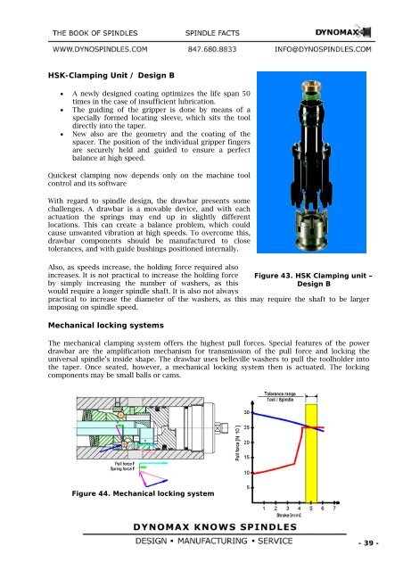
The mechanical clamping system offers the highest pull forces. Special features of the power<br />
drawbar are the amplification mechanism for transmission of the pull force and locking the<br />
universal <strong>spindle</strong>’s inside shape. The drawbar uses belleville washers to pull the toolholder into<br />
the taper. Once seated, however, a mechanical locking system then is actuated. The locking<br />
components may be small balls or cams.<br />
Figure 44. Mechanical locking system<br />
- 39 -