thumbwheel
mrt16-wp 12-24V.pub - CP Electronics
mrt16-wp 12-24V.pub - CP Electronics
- No tags were found...

Create successful ePaper yourself
Turn your PDF publications into a flip-book with our unique Google optimized e-Paper software.
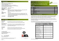
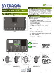
PRODUCT DATA AND INSTALLATION SHEET<br />
MRT16-WP WEATHERPROOF<br />
MULTI-RANGE TIME DELAY SWITCH<br />
(12 OR 24 V AC/DC VERSION)<br />
DESCRIPTION AND OPERATION<br />
The MRT16 series of time delay switches are designed to provide timed<br />
control of lighting, heating or ventilation loads. Using touch (light press<br />
required) activation the user can switch on a load for a preset time period<br />
and have the load turn off automatically after the time period has elapsed.<br />
Multiple timing ranges come as standard to allow the time out period to<br />
be set accurately. Time setting is achieved using switches and a <strong>thumbwheel</strong><br />
at the rear of the unit.<br />
Several modes of operation are selectable using switches:<br />
• On/off: triggering the timer will turn on the load and start the timing.<br />
Triggering the timer again during timing will immediately turn off the<br />
load and stop the timing.<br />
• Resetting: triggering the timer will turn on the load and start the timing.<br />
Triggering the timer again during timing will re-start the timing period<br />
from scratch. When using an external trigger In this mode, the timer will<br />
not start until the trigger is removed making it ideal for pump or fan<br />
overrun applications.<br />
• Non-resetting: triggering the timer will turn on the load and start the<br />
timing. Triggering the timer again during timing will have no affect.<br />
Optional neon indicators provide permanent illumination or illumination<br />
during the timing period.<br />
WIRING<br />
Wire the MRT16 timers as in diagram 1. Connection to the TRIG terminal is optional.<br />
Applying a live to the trigger terminal will start the timer running. A momentary switch can be used, for example, in corridor lighting applications. A<br />
permanent input can be used, for example, in pump overrun applications.<br />
To switch from more than one position simply wire two or more units in parallel to achieve two way and intermediate switching.<br />
When installing touch switches do not fix to a vibrating or uneven surface.<br />
Ensure that all cable entry to the enclosure is via suitable cable glands and seal with silicone sealant where appropriate.<br />
If it is necessary to screw through the rear of the enclosure, ensure that any holes are covered with the caps provided and sealed<br />
with silicone sealant where appropriate.<br />
Diagram 1 Standard Wiring<br />
Ref: %WD218 Issue 1
INSTALLATION<br />
Warning. This device works at mains potential. Be sure to take care when working with electricity.<br />
1. Make sure the load is connected and in working order.<br />
2. Isolate the mains supply to the circuit at the main consumer unit.<br />
3. Connect the controller via the terminal block. Live supply to the L terminal, Neutral to the N terminal and the load to the LIVE OUT terminal.<br />
Where required connect the external trigger to the TRIG terminal.<br />
4. Set the timing range according to the diagram below. Set the <strong>thumbwheel</strong> to the time setting (anticlockwise is minimum, clockwise is maximum).<br />
5. Set the function according to the diagram below (see above for description).<br />
6. Screw the unit to the wall and switch the mains supply back on at the distribution board.<br />
FAULT FINDING<br />
LOAD DOES NOT COME ON<br />
Check to see if the live supply to the circuit is<br />
good. Strap across the L and LIVE OUT terminal<br />
to check.<br />
LOAD DOES NOT GO OFF<br />
Check that the time setting is correct.<br />
When using external triggers, ensure that live is<br />
removed from the trigger terminal to enable the<br />
timer to start (for resetting mode only).<br />
SPECIFICATION<br />
LOAD<br />
16 Amp resistive load<br />
3 Amp inductive load<br />
SUPPLY VOLTAGE 12V version: 12 Volts AC/DC +/- 10%<br />
24V version: 24 Volts AC/DC +/- 10%<br />
TIMING PERIOD Adjustable 1 second to 2 hours in ranges<br />
TERMINAL CAPACITY 4.0mm 2<br />
IP RATING IP 66<br />
MATERIAL<br />
Polystyrene<br />
TYPE Class 2<br />
TEMPERATURE -10°C to 35°C<br />
CONFORMITY EMC-89/336/EEC<br />
LVD-73/23/EEC<br />
PART NUMBERS<br />
MRT16-WP 12V<br />
MRT16-WP 24V<br />
Weatherproof multi-range timer 12VAC/DC<br />
Weatherproof multi-range timer 24VAC/DC<br />
C.P. Electronics Ltd<br />
Unit 2 Abbey Manufacturing Estate<br />
Mount Pleasant, Wembley<br />
Middlesex. HA0 1RR<br />
IMPORTANT NOTICE!<br />
This device should be installed by a qualified electrician<br />
in accordance with the latest edition of the IEE wiring<br />
regulations.<br />
Due to our policy of continual<br />
product improvement CP<br />
Electronics reserves the right to<br />
alter the specification of this<br />
product without prior notice.<br />
Tel: + 44 (0) 20 8900 0671<br />
Fax: + 44 (0) 20 8900 0674<br />
www.cpelectronics.co.uk<br />
enquiry@cpelectronics.co.uk<br />
Ref: %WD218 Issue 1