characteristics
See Details Here - Utility Engineers
See Details Here - Utility Engineers
- No tags were found...

You also want an ePaper? Increase the reach of your titles
YUMPU automatically turns print PDFs into web optimized ePapers that Google loves.
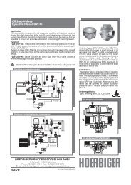
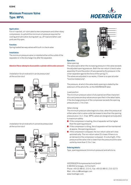
R284E<br />
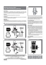
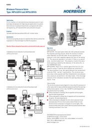
Minimum Pressure Valve<br />
Type: MPVL<br />
Application:<br />
For oil-injected, oil-lubricated screw compressors and other rotary<br />
compressors: to uphold the minimum oil pressure required for<br />
cooling and lubrication during start-up, off-load and when user<br />
ports are filly open.<br />
Function:<br />
Spring loaded two way valves with built-in check valve<br />
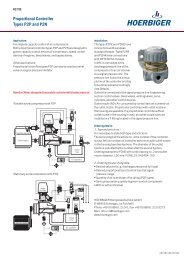
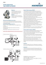
Installation:<br />
The minimum pressure valve is installed either at the outlet of the<br />
separator or in the discharge line after the separator.<br />
Attention! Never attempt to disassamble a cylinder whilst under pressure!<br />
Installation for air ends witch can be pressurized<br />
at the suction duct<br />
Operation:<br />
Valve opening<br />
The valve opens when the increasing pressure in the valve exceeds<br />
the adjusted opening pressure. Both the non-return (check) valve<br />
assembly (5) and the piston (4) are opened by the pressure in the<br />
oil/air separator against the force of the spring (7).<br />
The valves are adjusted in our works, if there is no special order<br />
"function tested only".<br />
The pressure, at which the valve starts opening is stated by the<br />
extension of the article No. on the HOERBIGER label.<br />
Load position<br />
The minimum pressure valve is fully opened and flow <strong>characteristics</strong><br />
and pressure drop values are as specified in the detail table,<br />
if the discharge pressure of the compressor exceeds the opening<br />
pressure plus 1.5 to 2 bar.<br />
Installation for air ends which cannot be pressurized<br />
at the suction duct<br />
Valve closing<br />
The minimum pressure valve begins to close, when the pressure at<br />
either valve inlet or valve outlet decreases to less than the opening<br />
pressure plus 1 to 1.5 bar. MPVL valves are designed and adjusted<br />
to maximum safety:<br />
n If the compressor is loading, the oil separator will be higher<br />
than the opening pressure<br />
n If the compressor is idling, the oil separator will be maintained<br />
at approx. the opening pressure<br />
n if the compressor is stopped, the non-return valve will close<br />
automatically. The non-return valve (5) closes if there is no<br />
air demand or the compressor is stopped. It is shut tight, if the<br />
pressure at the valve inlet is lower than the pressure at the valve<br />
outlet by more than 0.5 to 1 bar.<br />
Ordering details:<br />
Type, opening pressure (minimum pressure) and article no.<br />
HOERBIGER Kompressortechnik GmbH<br />
D-86956 Schongau, Im Forchet 5<br />
Phone +49 (0) 88 61 210-0, Fax +49 (0) 88 61 210-3273<br />
Mail: info-rcc@hoerbiger.com<br />
www.hoerbiger.com<br />
AKT4R284E200704
Details<br />
Type MPVL15B MPVL20B MPVL25B MPVL32B MPVL40B MPVL50B MPVL50F MPVL65B MPVL65F MPVL80F<br />
Nominal mm 15 20 25 32 40 50 50 65 65 80<br />
diameter DN<br />
Max. work. bar (g) 16<br />
press. PS<br />
Connections<br />
Datentabelle<br />
G1/2 G3/4 G1 G1 1/4 G1 1/2 G2 – G2 1/2 – –<br />
Flange design - - - - - - G2 - G2 1/2 G3<br />
connections<br />
Weight kg 0.35 0.45 0.8 1.1 1.5 3.3 5.7 5.8 9.5 13<br />
K V<br />
-value m 3 /h 4 5.5 9 15 24 40 40 64 64 100<br />
of the fully<br />
opened valve 2)<br />
Air intake m 3 /min recommended application range for pressure losses from 0.03 to 0.2 bar (g)<br />
capacity<br />
of the compressor<br />
Discharge bar (g) 5 to 16<br />
pressure<br />
of the compressor<br />
Medium oily pressurized air, filtered • recommended compressed air quality according to DIN ISO 8573-1, class 5<br />
Reference oil: see www.hoerbiger.com<br />
Start of opening 3) bar (g) 3 to 5, standard settings (±0.25 bar): 3.5 and 4.75<br />
Fully opened at 3) bar (g) opening pressure plus 1.5 to 2<br />
Closed at 3) bar (g) opening pressure minus 0.5 to 1<br />
Temperature range °C 0 to100 • short periods: - 25, +130 emergency stop (max. 10% working period at max.)<br />
Installation<br />
dimensions mm see dimension table, others upon request<br />
attitude<br />
optional<br />
Materials<br />
Aluminum alloy, Steel, Viton/NBR, PTFE<br />
1)<br />
DIN ISO 228, other thread executions upon request<br />
2)<br />
Valve fully open, measured to DIN IEC534 (values refer to specific weight 1000 kg/m 3<br />
3)<br />
see operation<br />
Diagram 1, recommended ranges of application
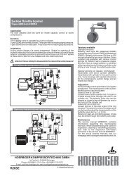
Maintenance:<br />
The service manual W283RCC contains information regarding<br />
the maintenance intervals. While disassembling the valve<br />
for inspection, cleaning or retrofitting purposes, also refer to<br />
the respective information contained in the service manual<br />
W283RCC. For the actual service manuals visit our homepage<br />
www.hoerbiger.com<br />
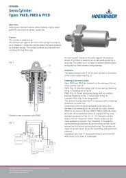
Pressure setting:<br />
Opening pressure:<br />
Valves supplied by HOERBIGER are set to the opening pressure.<br />
Precaution: The correct minimum pressure is vital for the function<br />
of the compressor. Tampering with adjustment may cause a<br />
compressor breakdown. Valves should be adjusted by authorized<br />
personal of the compressor manufacturer by using the accurate<br />
pressure gauge.<br />
For adjustment:<br />
Remove the plastic plug (9) and the pin (8) with a pair of pliers.<br />
Increase first the opening / minimum pressure by turning the ring<br />
(3) clockwise, one or two turns of the wrench. Then decrease the<br />
opening / minimum pressure by turning the ring (3) slowly and<br />
gradually counterclockwise. Secure the new setting by inserting<br />
the pin (8) into a new hole (to be drilled 2,5 mm into the ring 3).<br />
Check proper valve function on the compressor after maintenance<br />
or adjustment.<br />
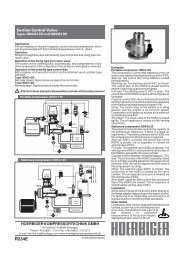
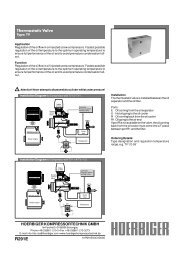
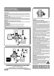
Dimensions<br />
MPVL..B<br />
MPVL..F<br />
Flanges<br />
MPVL50F<br />
MPVL65F<br />
MPVL80F<br />
lateral outlet<br />
flange<br />
inlet flange<br />
bottem view<br />
Main dimensions, inlet and outlet connections<br />
Dim. MPVL15B MPVL20B MPVL25B MPVL32B MPVL40B MPVL50B MPVL50F MPVL65B MPVL65F MPVL80F<br />
A G1/2 G3/4 G1 G1 1/4 G1 1/2 G2 – G2 1/2 – –<br />
B 43 50.5 56.5 67.5 67.5 78 100 93 103 125<br />
C 13 15 15 20 20 24 – 27 – –<br />
D 13 15 15 20 20 24 – 27 – –<br />
E 31 36 42.5 48 55 66 120 76 150 125<br />
F 36 46 55 50 65 85 85 95 95 115<br />
G 46 55 65 70 85 100 100 130 130 145<br />
H 110 124 138 175 214 240 262 317 321 389<br />
J – M5 M5 M8 M8 M10 M10 M10 M10 M12<br />
K – – – – – – 165 – 185 190,5<br />
L – – – – – – 22 – 24 24<br />
M – – – – – – 4xø18 – 4xø18 8xø18<br />
TKø125 – TKø145 TKø160<br />
N 1) – – – – – – – – – 2<br />
1)<br />
Valve is supplied with seals for installation between flanges without recesses.<br />
HOERBIGER can not grant any warranty for the correctness of technical or other data in catalogues, brochures and other printed material. HOERBIGER reserves the right to<br />
alter its products without notice. This also applies to products already on order provided that such alternations can be made without subsequential changes being necessary<br />
in specifications already agreed.