fallout fallout
See Details Here - Utility Engineers
See Details Here - Utility Engineers
- No tags were found...

Create successful ePaper yourself
Turn your PDF publications into a flip-book with our unique Google optimized e-Paper software.
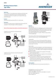
Thermostatic Valve<br />
Type: TV<br />
Application<br />
Regulation of the oil flow in oil-injected screw compressors. Fastest possible<br />
regulation of the oil temperature to the optimum operating temperature to<br />
ensure full performance of the oil and to avoid premature condensation <strong>fallout</strong>.<br />
Function<br />
Regulation of the oil flow in oil-injected screw compressors. Fastest possible<br />
regulation of the oil temperature to the optimum operating temperature to<br />
ensure full performance of the oil and to avoid premature condensation <strong>fallout</strong>.<br />
! Attention! Never attempt to disassemble a cylinder whilst under pressure!<br />
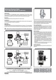
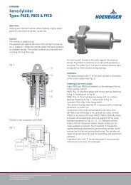
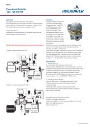
Installation Diagram for Compressor with TV 1/2-TV1<br />
Electric motor<br />
Injection pump<br />
Suction<br />
control<br />
valve<br />
Intake<br />
air filter<br />
Air end<br />
Controller...<br />
Pressure switch...<br />
Venting valve...<br />
Oil/air<br />
filter<br />
MPVL<br />
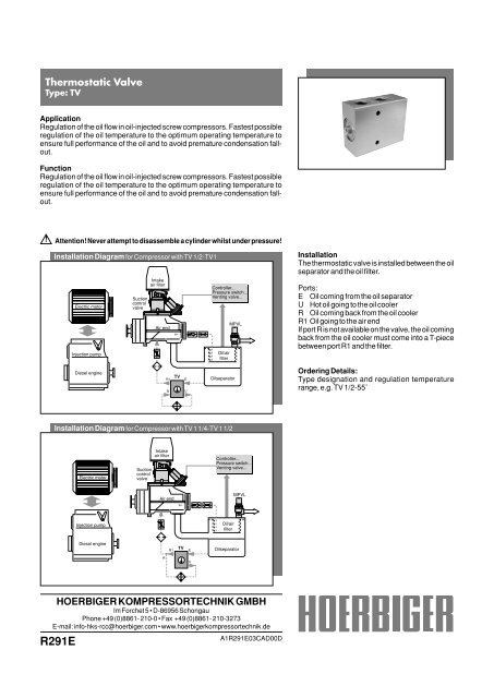
Installation<br />
The thermostatic valve is installed between the oil<br />
separator and the oil filter.<br />
Ports:<br />
E Oil coming from the oil separator<br />
U Hot oil going to the oil cooler<br />
R Oil coming back from the oil cooler<br />
R1 Oil going to the air end<br />
If port R is not available on the valve, the oil coming<br />
back from the oil cooler must come into a T-piece<br />
between port R1 and the filter.<br />
Diesel engine<br />
R1<br />
R<br />
TV<br />
E<br />
U<br />
Oilseparator<br />
Ordering Details:<br />
Type designation and regulation temperature<br />
range, e.g. TV 1/2-55˚<br />
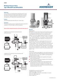
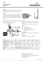
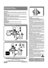
Installation Diagram for Compressor with TV 1 1/4-TV 1 1/2<br />
Electric motor<br />
Suction<br />
control<br />
valve<br />
Intake<br />
air filter<br />
Controller...<br />
Pressure switch...<br />
Venting valve...<br />
Air end<br />
MPVL<br />
Injection pump<br />
Oil/air<br />
filter<br />
Diesel engine<br />
R1<br />
TV<br />
E<br />
Oilseparator<br />
R<br />
U<br />
HOERBIGER KOMPRESSORTECHNIK GMBH<br />
Im Forchet 5 • D-86956 Schongau<br />
Phone +49 (0)8861- 210-0 • Fax +49 (0)8861- 210-3273<br />
E-mail: info-hks-rcc@hoerbiger.com • www.hoerbigerkompressortechnik.de<br />
R291E<br />
A1R291E03CAD00D
I<br />
I<br />
Details<br />
Type TV 1/2 TV 3/4 TV 1 TV 1 1/4 TV 1 1/2<br />
Nominal diameter DN mm 15 20 25 32 40<br />
Max. working bar (g) 16<br />
pressure PS<br />
Port sizes G1/2 G3/4 G1 G1 1/4 G1 1/2<br />
K V<br />
value m 3 /h 4 4 7 15 17<br />
Medium<br />
Mineral oils and synthetic oils (diester oils)<br />
Temperature range °C -10 to +110<br />
Regulation °C Version I: start of stroke: 55 - end of stroke: 70<br />
temperature range Version II: start of stroke: 70 - end of stroke: 85<br />
Max. flow rate, inlet l/min 45 70 140 180 400<br />
Dimensions mm See dimension table<br />
Materials<br />
Aluminium forging alloy, anodized, stainless steel, zinc-plated steel, brass, Viton<br />
Weight kg 0.8 0.9 1.6 1.7 2.3<br />
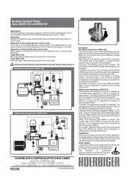
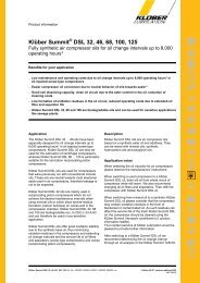
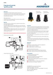
Dimensions, Type: TV 1 /2, TV 3 /4<br />
Dimensions, Type: TV 1<br />
C<br />
R , U<br />
F<br />
D<br />
E<br />
K<br />
R<br />
A<br />
K<br />
U<br />
U<br />
C<br />
P<br />
O<br />
R<br />
F<br />
K<br />
D<br />
A<br />
K<br />
H<br />
I<br />
I<br />
E<br />
G<br />
B<br />
L<br />
J<br />
E<br />
I<br />
I<br />
I<br />
R<br />
U<br />
B<br />
E<br />
K<br />
L<br />
J<br />
R1<br />
M<br />
K<br />
R1<br />
I<br />
R1, E<br />
H<br />
R1<br />
K<br />
M<br />
G<br />
N<br />
K<br />
E<br />
Dimensions, Type: TV 1 1 /4, TV 1 1/2<br />
A<br />
F<br />
C<br />
K<br />
J<br />
R1<br />
R1<br />
E<br />
B<br />
L<br />
Type: TV 1 1/ 4<br />
U<br />
U<br />
K<br />
M<br />
Type: TV 1 1/ 2<br />
J<br />
U<br />
G<br />
A<br />
H<br />
I<br />
H<br />
E<br />
E<br />
K<br />
G E<br />
Dimension Table (dimension in mm)<br />
Type TV 1/2 TV 3/4 TV 1 TV 1 1/4 TV 1 1/2<br />
A 100 105 120 120 140<br />
B 80 80 100 110 120<br />
C 40 45 60 60 70<br />
D 59 59 70 - -<br />
E 40 40 17 20 15<br />
F 22.5 21 24 32.5 39<br />
G 50 50 50 70 90<br />
H 15 15 7.5 24.5 14.5<br />
I 14 16 20 20 20<br />
J ø7 ø7 ø8 ø10.5 ø10,5<br />
K G1/2 G3/4 G1 G1 1/4 G1 1/2<br />
L M5 M5 M5 M5 M5<br />
M 22.5 21 32.5 60 75.5<br />
N - - 98 - -<br />
O - - 22 - -<br />
R , R1, U , E = Names of connections<br />
HOERBIGER can not grant any warranty for the correctness of technical or other datas in catalogues, brochures and other printed material. HOERBIGER reserves<br />
the right to alter its products without notice. This also applies to products already on order provided that such alternations can be made without subsequential changes<br />
being necessary in specifications already agreed.