BENSON VARIANTE RANGE
Benson BV Range
Benson BV Range
- No tags were found...

Create successful ePaper yourself
Turn your PDF publications into a flip-book with our unique Google optimized e-Paper software.
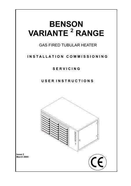
<strong>BENSON</strong><br />
<strong>VARIANTE</strong> 2 <strong>RANGE</strong><br />
GAS FIRED TUBULAR HEATER<br />
I N S T A L L A T I O N C O M M I S S I O N I N G<br />
S E R V I C I N G<br />
U S E R I N S T R U C T I O N S<br />
Issue 2<br />
March 2005<br />
1
Section Contents Page No<br />
1.0 Compliance Notices 4<br />
1.1 Certificates of Conformity 5<br />
1.2 General product Information 5<br />
1.3 General Requirements 6<br />
1.4 Delivery & Pre-installation Checks 6<br />
1.5 Warranty 7<br />
Special risk areas 7<br />
2.0 Installation 8<br />
2.1 Installation Clearances and Mounting Heights 8<br />
2.2 Heater Mounting 9<br />
2.3 Warm Air Circulation 10<br />
2.4 Air Supply 10<br />
2.5 Flue Installation 11<br />
2.6 Electrical Installation 19<br />
2.7 Gas Installation 20<br />
3.0 Commissioning 21<br />
3.1 Electrical Pre tests 21<br />
3.2 Ignition Sequence 21<br />
3.3 Hand Over 23<br />
4.0 Servicing 23<br />
4.1 Servicing Procedure 23<br />
5.0 Fault Diagnosis 25<br />
6.0 Wiring Diagrams 27<br />
7.0 Technical Data 30<br />
7.1 Technical Data Common Information 30<br />
7.2 Technical Data Heater Specifications 31<br />
8.0 Parts Listing 33<br />
9.0 Dimensions 35<br />
2
IMPORTANT NOTICE TO INSTALLERS<br />
Installers should satisfy themselves that the gas pipework installation is carried<br />
out in accordance with all current legislation, Codes of Practice and<br />
recommendations .<br />
Additionally it may be necessary to protect the gas valves which form part of<br />
the heater or burner assembly from potential pipe contamination particularly,<br />
but not exclusively , where copper gas pipework is used.<br />
In instances where copper pipework is to be used for all or part of a gas<br />
pipework installation, including short length final connections then we advise<br />
that installers consult with gas supplier or provider and satisfy themselves what<br />
additional precautions may be necessary<br />
Any reference made to Laws, Standards, Directives , Codes of Practice or other<br />
recommendations governing the application and installation of heating appliances and<br />
which may be referred to in Brochures, Specifications, Quotations, and Installation,<br />
Operation and Maintenance manuals is done so for information and guidance<br />
purposes only and should only be considered valid at the time of the publication.<br />
Benson Heating cannot be held responsible from any matters arising from the revision<br />
to or introduction of new Laws, Standards, Directives, Codes of Practice or other<br />
recommendations.<br />
3
1.0 Compliance notices<br />
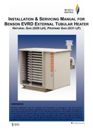
The Benson Variante range of warm air<br />
heaters detailed herewith are manufactured<br />
by Benson Heating within a strictly controlled<br />
environment within the parameters of<br />
ISO9001: 2000<br />
These instructions are only valid if the<br />
following country code is on the appliance<br />
GB. IE. If this code is not present on the<br />
appliance, it is necessary to refer to the<br />
technical instructions which will provide the<br />
necessary information concerning the<br />
modification of then appliance to the<br />
conditions of use for the country.<br />
The Benson Variante Range has been<br />
independently tested and assessed, and has<br />
been found to meet the Essential<br />
Requirements of the following European<br />
Directives.<br />
Gas Appliance Directive (90 / 396 / EEC)<br />
Machinery Directive (89 / 392 EEC)<br />
Low Voltage Directive (73 / 23 / EEC & 93 /<br />
68 / EEC)<br />
Electromagnetic Compatibility Directive (98 /<br />
336 / EEC & 91 / 31 / EEC)<br />
Product Liability Directive 65 / 374 / EEC)<br />
The manufacturer has taken reasonable and<br />
practical steps to ensure that Benson<br />
Variante Range of Heaters are safe and<br />
without risk when properly used. These<br />
heaters should therefore only be used in the<br />
manner and purpose for which they were<br />
intended, and in accordance with the<br />
recommendations detailed herewith.<br />
Where proprietary items are incorporated<br />
into Benson Heating products, detailed<br />
information and instructions are also<br />
provided as part of the information pack.<br />
It is the responsibility of the installer, owner,<br />
user, or hirer, of such products supplied by<br />
Benson Heating, to ensure that they are<br />
familiar with the appropriate information/<br />
manuals, supplied by the manufacturer, and<br />
that they are suitably aware of the purpose of<br />
the manuals and the safety instructions. In<br />
addition, operators must be suitably trained<br />
in the use of the appliance so as to ensure its<br />
continued safe and efficient use.<br />
Benson Heating has a commitment to<br />
continuous improvement, and therefore<br />
reserves the right to amend or change the<br />
specification of the Variante Heater range<br />
subject to agreement from The Notified<br />
Body.<br />
Contained within the text of the manual, the<br />
words 'Caution' and 'Warning' are used to<br />
highlight certain points.<br />
Caution is used when failure to follow or<br />
implement the instruction (s) can lead to<br />
premature failure or damage to the heater or<br />
its component parts.<br />
Warning is used when failure to heed or<br />
implement the instruction (s) can lead to not<br />
only component damage, but also to a<br />
hazardous situation being created where<br />
there is a risk of personal injury.<br />
The heaters have been designed,<br />
manufactured, assembled, inspected, and<br />
tested, with safety and quality in mind, there<br />
are certain basic precautions which the<br />
installer and user should be aware of, and<br />
they are strongly advised to read the<br />
appropriate sections of the information pack<br />
accompanying the heater, prior to installation<br />
or use.<br />
The Benson Variante range of heaters<br />
conform to the following European<br />
Harmonised Standards.<br />
BS EN 1020 Requirements for non domestic<br />
gas fired forced convection air heaters for<br />
space heating incorporating a fan to assist<br />
transportation of combustion air and/ or<br />
combustion products.<br />
Benson Heating supports all new products<br />
being supplied to their customers with a<br />
comprehensive information pack; this clearly<br />
defines mandatory instructions for the safe<br />
installation, use, and maintenance, of the<br />
Appliance (s).<br />
BS EN-ISO 12100-1:2003 &<br />
BS EN - ISO12100-2:2003<br />
Safety of Machinery - Basic Concepts,<br />
General Principles for Design<br />
Part 1 & Part 2<br />
4
BS EN 60204 - Part 1 : 1993<br />
Safety of Machinery - Electrical Equipment<br />
for Machines Specification for General<br />
Requirements<br />
BS EN 60335 - Part 1 : 1988<br />
Safety of Household and Similar Electrical<br />
Appliances General Requirements<br />
BS EN 55014 - 1993<br />
Limits and methods of measurement of radio<br />
disturbance characteristics of electrical<br />
motor-operated and thermal appliances for<br />
household and similar purposes, electrical<br />
tools and similar electric apparatus<br />
BS EN 50165 - 1995<br />
Electrical Equipment of non-electric heating<br />
appliances for household and similar<br />
purposes, safety requirements<br />
The Benson Variante range of gas unit<br />
heaters meet with the governments criteria in<br />
respect of the Enhanced Capital Allowance<br />
Scheme<br />
1.1 Certificates of conformity<br />
Declarations and Certificates are available<br />
upon request from the Quality Control<br />
Department at Benson Heating .<br />
Notified Body PIN Reference is<br />
063BQ5461<br />
1.2 General product information<br />
The Benson Variante range includes for 10<br />
model sizes with outputs from 12.0 kW to<br />
144.0 kW,<br />
Each model can be configured for use as<br />
axial fan crossflow (VRA/X) centrifugal fan<br />
(VRC) and axial fan downflow (VRE)<br />
Variante heaters are suitable for operation on<br />
natural gas (G20) or LPG (Propane G31)<br />
The Model Range is made up as follows<br />
Model No 40 70 100 135 170<br />
Output kW 12 19.6 24.9 39.2 49.0<br />
Model No 200 250 330 410 490<br />
Output kW 58.8 72.0 96.0 120.0 144.0<br />
Variante heaters have been approved for<br />
alternative flue discharge arrangements<br />
These are detailed in following page’s<br />
Cabinet<br />
Manufactured from electro-zinc coated steel,<br />
finished in a durable stove enamelled<br />
polyester powder paint.<br />
Heat Exchanger<br />
Manufactured from aluminised dimpled steel<br />
tube formed into a W shape to give<br />
enhanced efficiency .<br />
Flue / Combustion Air Spigot<br />
Each heater is fitted with two spigots both of<br />
which are located to the rear of the appliance<br />
One of the pair is for connection for the flue<br />
whilst the other is a screened combustion air<br />
intake<br />
Burner<br />
The induced draught multi in-shot burner<br />
assembly is manufactured from aluzinc<br />
coated steel and mounted to a common steel<br />
manifold which can be easily withdrawn<br />
through the burner access compartment.<br />
Burner Control<br />
The heaters are fitted with automatic<br />
ignition for all models within the range.<br />
Exhaust Fan<br />
Combustion gases are evacuated to<br />
atmosphere via an in built power flue venter<br />
fan which is safety interlocked to the gas<br />
valve via an air pressure proving device<br />
Air Movement Fan<br />
VRA/ X / E) are supplied with an Axial fan for<br />
free blowing applications .<br />
Variante (C) are supplied with Centrifugal<br />
fans suitable for ducted applications Note<br />
Neither asbestos nor soft soldered joints are<br />
used in the construction or manufacture of<br />
the Benson VRA/X/C/E range of Heaters.<br />
The materials selected for use can withstand<br />
the mechanical, chemical, and thermal<br />
stresses which they will be subject to during<br />
foreseen normal use when installed in<br />
5
accordance with the manufacturers<br />
recommendations.<br />
electrical services, wiring routes, and if<br />
appropriate, any additional controls.<br />
1.3 General Requirements<br />
Caution<br />
Before installation, check that the local<br />
distribution conditions, nature of gas and<br />
pressure, and the current state adjustment of<br />
the appliance are compatible.<br />
Warning<br />
Unauthorised modifications to the appliance,<br />
or departure from the manufacturers<br />
guidance on intended use, or, installation<br />
contrary to the manufacturers<br />
recommendations may constitute a hazard.<br />
Note<br />
To ignore the warning and caution notices,<br />
and to ignore the advice from the<br />
manufacturer on installation, commissioning,<br />
servicing, or use, will jeopardise any<br />
applicable warranty, moreover, such a<br />
situation could also compromise the safe and<br />
efficient running of the appliance itself, and<br />
thereby constitute a hazard.<br />
This appliance must be installed by a<br />
competent person and in accordance with<br />
European, National, and Local criteria,<br />
including any relevant standards, codes of<br />
practice the requirements of the current<br />
building Regulations (and in particular parts<br />
J & L), Health and safety regulations IEE<br />
regulations and any requirements of the local<br />
Authority, Fire Officer or insurers<br />
Relevant standards may include BS6230,<br />
BS6891 and BS5588 parts 2 and 3<br />
Prior to installation the following points<br />
should be considered;<br />
a) The position of the heater for the optimum<br />
efficient distribution and circulation of warm<br />
air<br />
b) The position of the heater relative to the<br />
route of the flue<br />
c) The position of the heater relative to the<br />
supply of gas<br />
d) The position of the heater relative to the<br />
e) The position of the heater relative to the<br />
supply of fresh air<br />
f) The position of the heater relative to<br />
potential stratification / circulation problems,<br />
which generally occur at higher levels and<br />
which may be overcome through the<br />
provision of a suitable de-stratification unit.<br />
g) The position of the heater relative to<br />
service and maintenance requirements<br />
Caution<br />
The heater must not be installed within an<br />
area where the conditions are unsuitable,<br />
e.g. where the atmosphere is highly<br />
corrosive, has a high degree of salinity, or<br />
where high wind velocities may affect burner<br />
operation. Suitable protection should be<br />
provided for the appliance when it is located<br />
in a position where it may be susceptible to<br />
external mechanical damage from; for<br />
example, fork lift trucks, overhead cranes<br />
etc.<br />
1.4 Delivery and pre-installation<br />
checks<br />
The heater is supplied wrapped in heavy<br />
duty protective polythene, mounted on a<br />
pallet.<br />
On receipt of the heater, the following<br />
checks should be carried out;<br />
a) The model is as per order<br />
b) That it is undamaged<br />
c) That it is suitable for the gas supply and<br />
pressure<br />
d) That it is suitable for the electrical supply<br />
If any of these points are not satisfied then<br />
contact should be made with the Sales Office<br />
at Benson Heating as soon as possible by<br />
telephoning 01547-528534. In the case of<br />
claims for damage, this must be reported in<br />
writing within 24 hours of delivery, in order to<br />
comply with insurance criteria<br />
6
1.5 Warranty<br />
The heater is supplied with a 1 year parts<br />
and labour warranty and a further year on all<br />
parts excluding consumable’ s.<br />
In addition to this there is also a 10 year<br />
time related warranty on the combustion<br />
chamber.<br />
The warranty commences from the date of<br />
dispatch from the manufacturer, and is<br />
subject to the terms detailed within the<br />
Benson Heating 'conditions of business'.<br />
Note (i)<br />
The warranty may be invalidated if -<br />
a) The warranty registration/commissioning<br />
card has not been completed and returned to<br />
Benson Heating<br />
b) The installation is not in accordance with<br />
the general requirements of this manual<br />
c) The flue arrangement and air supply for<br />
the heater are not in accordance with the<br />
manufacturers recommendations, codes of<br />
practice, or similar standards<br />
d) Air flow through the heater is not in<br />
accordance with the manufacturers technical<br />
specifications<br />
e) Internal wiring on the heater has been<br />
tampered with or unauthorised service/<br />
repairs undertaken<br />
f) The main electrical supply input to the<br />
heater has been interrupted during the<br />
heating mode<br />
g) The heater has been subject to and<br />
affected by the ingress of water in any form<br />
h) The heater is not operated at the rating(s)<br />
laid down in the manufacturers technical<br />
specifications<br />
i) The heater has not been operated or used<br />
within the normal scope of its intended<br />
application<br />
j) The manufacturer's recommended<br />
minimum service requirements have not<br />
been complied with<br />
Note (ii)<br />
All warranty claims must contain the<br />
following information to enable processing to<br />
take place;<br />
(1) Heater model<br />
(2) Heater serial number<br />
(3) Order reference/date of order, together<br />
with full installation details<br />
(name and address)<br />
(4) Details or symptoms of fault<br />
(5) Installers name and address.<br />
Faulty parts must be returned to the Benson<br />
Heating Spares Department, the address of<br />
which is provided on the cover of this<br />
manual. Any such parts will undergo<br />
inspection to verify the claim. Replacement<br />
parts supplied prior to this may be charged,<br />
and a credit supplied upon subsequent<br />
validation of the warranty claim.<br />
Consumable items are specifically not<br />
included within the scope of the warranty.<br />
Note (iii)<br />
Notification is required immediately a fault is<br />
suspected.<br />
The manufacturer will not accept<br />
responsibility for any additional damage that<br />
has been caused, expense incurred, or<br />
consequential loss resulting from any failure<br />
of the heater(s).<br />
SPECIAL RISK AREAS<br />
Where it is proposed to install a heater<br />
within a special risk area (e.g. an area<br />
containing flammable vapours where petrol<br />
engined vehicles are stored parked or<br />
serviced where paint spraying occurs, or<br />
where woodworking machinery or other<br />
flammable dust creating process’s are<br />
employed then restrictions, additional<br />
regulations concerning the heater flue wiring<br />
or controls may apply.<br />
It is strongly recommended that you contact<br />
Benson Technical before installation<br />
Caution<br />
When used in room sealed mode it may be<br />
possible to install Variante heaters in areas<br />
containing flammable vapours, high levels of<br />
airborne dust combustible dust chlorinated or<br />
halogenated hydrocarbons degreasing<br />
solvents styrenes other laminating materials<br />
or airborne silicones. Benson Technical<br />
7
should be contacted before installation .<br />
Failure to do so may invalidate or reduce<br />
guarantee cover.<br />
Plant Room Siting<br />
Provided certain criteria are met it is possible<br />
to install VRC (centrifugal fans) within a plant<br />
room heaters installed in plant rooms should<br />
only be configured for use in room sealed<br />
mode and provision should be made for the<br />
positive connection of flues , combustion air<br />
pipes, warm air discharge and return<br />
ductwork where such a siting is a<br />
requirement it is recommended that you<br />
consult Benson Technical prior to installation<br />
Additionally the maximum temperature within<br />
the plant room should not exceed 32 0 C<br />
2.0 Installation<br />
The location chosen for the heater must<br />
allow for the fitting of an effective flue<br />
system.<br />
The location must also allow for adequate<br />
clearance for the air supply, return air<br />
circulation, gas supply, electrical supply,<br />
whilst also providing good and safe working<br />
access.<br />
The heater must be installed so that it is<br />
level, supports for the heater must be<br />
sufficiently robust to withstand the weight of<br />
the heater and any ancillary equipment<br />
Any combustible material adjacent to the<br />
heater or flue system must be so placed or<br />
shielded so that its surface temperature does<br />
not exceed 65 0 C. Generally a free blowing<br />
heater should be located at a height<br />
(measured from floor level to the base of<br />
unit) as detailed within section 2.1<br />
VRA/X free blowing heaters are at their most<br />
effective when located as close to the<br />
working area as possible. However care<br />
should be exercised to avoid directing the<br />
discharged air directly onto the occupants of<br />
the area to be heated.<br />
Where the passage of cold air causes<br />
problems (e.g. by entrances, loading bays<br />
etc) it is considered favourable if the heater<br />
is positioned so as the discharge towards or<br />
across the cold air source from a distance<br />
from 1.5m - 6m dependent upon the size of<br />
the entrance and the air throw characteristics<br />
of the heater. On exposed walls heaters<br />
should be positioned so as to discharge<br />
towards, or along the length of the exposed<br />
wall.<br />
In areas where it is proposed that more than<br />
one heater is to be installed, a general<br />
scheme of circulation should be drawn up<br />
and maintained, thereby offering the best<br />
heat distribution. Air pressure within the area<br />
heated and the outside air pressure must<br />
remain the same, factors influencing this<br />
would be the presence of extraction systems,<br />
ventilation systems, and various types of<br />
process plant.<br />
VRA/X heaters are only suitable for free<br />
blowing applications or where the duct length<br />
does not exceed 2 metres.<br />
In which case the cross- section of the duct<br />
must be at least the same as that of the<br />
heater discharge grille<br />
VRE heaters configured for down flow<br />
applications should be suspended centrally<br />
over the area into which the warm air is to be<br />
discharged .<br />
2.1 Installation Mounting Heights and<br />
Clearances<br />
Model<br />
VRA/C<br />
40 70 100 135 170<br />
Min 1.8 1.8 2.0 2.0 2.4<br />
Max 2.3 2.3 2.5 2.5 3.0<br />
VRX Max 3.0 3.0 3.2 3.2 4.0<br />
Model<br />
VRA/C<br />
200 250 330 410 490<br />
Min 2.4 2.4 2.4 2.4 2.4<br />
Max 3.0 3.5 3.5 3.5 3.5<br />
VRX Max 4.0 5.0 5.0 5.0 5.0<br />
Model<br />
VRE<br />
40 70 100 135 170<br />
Min 3.5 4.0 4.0 4.0 5.0<br />
Max 4.5 5.5 6.0 7.0 8.0<br />
Model<br />
VRE<br />
200 250 330 410 490<br />
Min 5.0 5.0 6.0 6.0 6.0<br />
Max 12.0 8.0 10.0 12.0 12.0<br />
8
Clearances VRA / X in mm<br />
Model 40 70 100 135 170 200 250 330 410 490<br />
Above 300 300 300 300 300 300 300 300 300 300<br />
Below 300 300 300 300 300 300 300 300 300 300<br />
Right side 250 250 250 250 250 250 250 250 250 250<br />
Left side 800 800 800 800 800 800 950 950 950 950<br />
Rear 500 500 600 700 850 950 700 850 1050 1200<br />
Clearances VRC in mm<br />
Model 40 70 100 135 170 200 250 330 410 490<br />
Above 300 300 300 300 300 300 300 300 300 300<br />
Below 300 300 300 300 300 300 300 300 300 300<br />
Right side 250 250 250 250 250 250 250 250 250 250<br />
Left side 800 800 800 800 800 800 950 950 950 950<br />
Rear 200 200 200 200 200 200 200 200 200 200<br />
Clearances VRE in mm<br />
Model 40 70 100 135 170 200 250 330 410 490<br />
Above 1500 1500 1500 1500 1500 1500 1500 1500 1500 1500<br />
Below 4000 4000 4000 4000 5000 5000 6000 6000 6000 6000<br />
Right side 250 250 250 250 250 250 250 250 250 250<br />
Left side 800 800 800 800 800 800 950 950 950 950<br />
Rear 250 250 250 250 250 250 250 250 250 250<br />
Left hand side = burner compartment side<br />
2.2 Heater Mounting<br />
The heater and flue must be adequately<br />
supported by one of the following methods ;<br />
a) Suspension by steel drop rods or straps<br />
from the M10 fixing points located on top of<br />
the heater<br />
These must be of sufficient strength to<br />
safely carry the weight of the unit and<br />
ancillary equipment. The straps may only<br />
drop vertically to eyebolts, if used; I.E. They<br />
must not be joined to the eyebolt at an angle<br />
to the vertical, and eyebolts if used should be<br />
of an approved type.<br />
b) VRA/X heaters can be mounted on<br />
specifically designed cantilever wall or<br />
vertical stanchion brackets which locate<br />
directly to the four M10 fixings on the heater<br />
casing.<br />
Alternatively VRA/X or VRC units can be<br />
mounted on cantilever type wall brackets<br />
however consideration must be given to<br />
ensure that the bracket is large enough to<br />
support the heater whilst providing the<br />
necessary clearances<br />
In either case the installer should ensure that<br />
the wall wall fixings or other support medium<br />
is capable of supporting the weight<br />
9
The Heater must be installed within the<br />
mounting heights indicated below<br />
The following heights in metres<br />
c) On a level non-combustible surface<br />
capable of adequately supporting the weight<br />
of the unit and ancillary equipment .<br />
2.3 Warm Air Circulation<br />
The air heater should be positioned to enable<br />
maximum circulation of discharged warm air<br />
within the area to be heated, whilst taking<br />
account of personnel within the area,<br />
sources of cold air ingress , and obstructions.<br />
Ensure louvres are adjusted outwards<br />
and ensure blades are not resonating<br />
The air temperature rise on passing the heat<br />
exchanger is typically around 34 0 C<br />
A full and unobstructed return air path to the<br />
air heater must be provided<br />
(see 2.4 Air Supply).<br />
Where the heater is positioned to deliver<br />
blown air through an opening in a wall, return<br />
air intakes should be located so that they<br />
cannot become blocked. Similarly these<br />
intakes must be positioned so as not to draw<br />
in odours, fumes, hazardous vapours or<br />
particles.<br />
2.4 Air Supply<br />
Provision must be made for the existence of<br />
an air supply in order to satisfy both<br />
combustion and ventilation criteria.<br />
It is a requirement that the area where the air<br />
heater is located must have a permanent air<br />
vent of negligible resistance direct to the<br />
outside air.<br />
Such air vents must be positioned so as not<br />
to become blocked or flooded, nor should<br />
they be placed so as to introduce<br />
undesirable matter (e.g. flammable, volatile,<br />
or aggressive chemicals/compounds or<br />
potentially hazardous or harmful substances)<br />
either direct from the outside, or through their<br />
proximity to an adjacent extraction system.<br />
Note<br />
It is strongly recommended that BS 6230 :<br />
1991 is referred to for further information<br />
concerning ventilation requirements<br />
Where mechanical ventilation is used it is a<br />
requirement that the inlet is of the<br />
mechanical type, and the outlet is either<br />
mechanical or natural.<br />
2.4.1 Heaters installed within the<br />
heated space<br />
Where heaters are installed within the space<br />
to be heated (e.g. not a plant room separate<br />
room, or compartment then<br />
Combustion and general ventilation<br />
is not required if<br />
The combustion air intake is ducted to<br />
atmosphere (i.e. Room Sealed Appliance)<br />
OR<br />
The design air change rate of the building is<br />
more than 0.5 air changes per hour and the<br />
volume of the space is greater than 4.7m 3<br />
per kilowatt of the total rated heat input<br />
Combustion and general ventilation<br />
is required if<br />
The appliance is not provided with<br />
combustion ductwork e.g. the air for<br />
combustion is taken from the space being<br />
heated<br />
And<br />
The building design air change rate is less<br />
than 0.5 air changes per hour and the<br />
volume of the space is greater than 4.7m 3<br />
per kilowatt then low level ventilation is<br />
required<br />
Where combustion air ventilation is required<br />
as dictated by the previous criteria then that<br />
ventilation can be via permanent ventilation<br />
openings / grilles situated at low level (I.e.<br />
below the flue takeoff spigot ) and with the<br />
free area of such grilles as :-<br />
For heaters with a rated input of less than<br />
60 kW — 4.5 cm 2 per kW of heat input<br />
For heaters with a rated input of more than<br />
60 kW — 270 cm 2 plus for each kW of rated<br />
input over the 60 kW threshold an additional<br />
4.5 cm 2<br />
Or by mechanical input (not extract)<br />
ventilation in association with either<br />
mechanical or natural extract and with a<br />
ventilation flow rate of 1.08m 3 /h per kW of<br />
10
total rated input<br />
Where mechanical extract is used to<br />
complement the above then the extract rate<br />
shall be 2.16m 3 /h per kW of rated heat input<br />
Mechanical ventilation systems where fitted<br />
must be provided with safety interlocks to<br />
prevent heater operation in the event of<br />
airflow failure.<br />
Where the combustion air intake is not<br />
ducted to atmosphere heater installed in<br />
flue only configuration then ventilation can<br />
be via a permanent ventilation opening /<br />
grille situated at both Low level (Inlet) and<br />
high Level (Outlet) and with the free area of<br />
such grilles as :-<br />
Low level (Inlet)<br />
2.4.2<br />
Heaters installed Within a Plant Room<br />
Where the heater is installed within a plant<br />
room ,separate room or compartment then<br />
combustion and general ventilation<br />
is always required<br />
Where the combustion air intake is ducted to<br />
atmosphere (i.e. Room Sealed Appliances)<br />
Then that ventilation can be via a permanent<br />
ventilation / grille situated at both low level<br />
(inlet) and high level (outlet) and with the free<br />
area of such grilles as :-<br />
For heaters with a rated input of less than<br />
60 kW — 9.0 cm 2 per kW of heat input<br />
For heaters with a rated input of more than<br />
60 kW — 540 cm 2 plus for each kW of rated<br />
input over the 60 kW threshold an additional<br />
4.5 cm 2<br />
High Level (Outlet)<br />
For heaters with a rated input of less than<br />
60 kW — 4.5 cm 2 per kW of heat input<br />
Low level (Inlet)<br />
For heaters with a rated input of less than<br />
60 kW — 4.5 cm 2 per kW of heat input<br />
For heaters with a rated input of more than<br />
60 kW — 270 cm 2 plus for each kW of rated<br />
input over the 60 kW threshold an additional<br />
2.25 cm 2<br />
High Level (Outlet)<br />
For heaters with a rated input of less than<br />
60 kW — 4.5 cm 2 per kW of heat input<br />
For heaters with a rated input of more than<br />
60 kW — 270 cm 2 plus for each kW of rated<br />
input over the 60 kW threshold an additional<br />
2.25 cm 2<br />
Alternatively mechanical input (not extract)<br />
ventilation may be used in association with<br />
either mechanical or natural extract and with<br />
a ventilation flow rate of 2.16m 3 /h per kW of<br />
total rated input.<br />
Mechanical ventilation systems where fitted<br />
must be provided with safety interlocks to<br />
prevent heater operation in case of air flow<br />
failure<br />
For heaters with a rated input of more than<br />
60 kW — 270 cm 2 plus for each kW of rated<br />
input over the 60 kW threshold an additional<br />
2.25 cm 2<br />
Alternatively mechanical input (not extract)<br />
ventilation may be used in association with<br />
either mechanical or natural extract , and<br />
with a ventilation flow rate of 3.24m 3 /h per<br />
kW of total rated input<br />
Where mechanical extract is used to<br />
complement the above then the extract rate<br />
shall be 2.06m 3 /h per kW of rated heat input<br />
Mechanical ventilation systems where fitted<br />
must be provided with safety interlocks to<br />
prevent heater operation in case of air flow<br />
failure<br />
2.4.3 Ventilation Openings and Grilles<br />
Ventilation openings and grilles must<br />
communicate directly with the outside air, be<br />
of negligible resistance and shall be sited so<br />
that they cannot easily be blocked of flooded<br />
2.5 Flue Installation.<br />
An integral flue spigot is fitted to all Variante<br />
Air Heaters thereby allowing the flue to<br />
connect directly to the heater.<br />
11
Warning<br />
It is essential that the products of combustion<br />
are flued to the outside of the building.<br />
Each heater must have its own separate flue,<br />
with a flue diameter of not less than is<br />
detailed in section 7.2 within this manual.<br />
The flue assembly must comply with all the<br />
relevant regulations regarding height and<br />
materials, and must terminate with an<br />
approved flue terminal.<br />
Care should be taken to ensure that the flue<br />
terminal is not situated in a high pressure<br />
area, the proximity of buildings and other<br />
obstacles which will influence this must be<br />
taken into account, preferably at the design<br />
stage.<br />
All Variante Heaters are equipped with a built<br />
in flue venter fan which prevents the<br />
re circulation of combustion products,<br />
consequently an external draught diverter,<br />
barometric damper, or anti spillage system<br />
must not be installed. Such devices are<br />
unnecessary on the BVA/C range of heaters.<br />
Horizontal flue installations must not<br />
exceed the following<br />
VRA/C/X 040 3 Metres overall length.<br />
VRA/C/X 070/200 6 Metres overall length.<br />
VRA/C/X 250/490 8 Metres in overall length.<br />
Each 90 0 bend corresponds to 1Mtr of flue<br />
length<br />
Each 45 0 bend corresponds to 0.8 Mtr of flue<br />
length<br />
Flue pipe should be supported at intervals<br />
not exceeding 1.8mtrs<br />
In order to provide adequate natural draught,<br />
the minimum length of horizontal flue must<br />
not be less than 1M.<br />
For vertical flue installations the flue should<br />
rise vertically where possible bends should<br />
not exceed 45 0 and the number of bends<br />
should be kept to a minimum.<br />
Maximum vertical flue length must not<br />
exceed 10 Metres<br />
The temperature of the combustion products<br />
can be as high as 170 0 C and therefore tend<br />
to rise naturally within the flue. Unnecessary<br />
bends and restrictions should therefore be<br />
avoided.<br />
Provision for the disconnection of the flue for<br />
servicing and inspection purposes must also<br />
be made.<br />
The position of the flue and its terminal<br />
should be such that it does not impair the<br />
combustion process. It should terminate in<br />
an exposed position so as to allow the free<br />
escape of flue gases without risk of their reentering<br />
the building through windows,<br />
ventilation ports etc.<br />
The following distances in mm’s should<br />
be observed<br />
200 below guttering or eaves<br />
300 from corners or openings (windows<br />
doors etc) and from other horizontal<br />
terminals on same wall<br />
1200 from a facing surface<br />
1500 from another terminal vertically on the<br />
same wall<br />
2000 from ground level<br />
The heaters must be connected to the flue<br />
system supplied by Benson Heating and be<br />
capable of withstanding the stresses and<br />
loadings associated with normal use.<br />
When designing the flue system the<br />
prevention of the formation and entrapment<br />
of condensation must be a key consideration.<br />
Horizontal flue should be fitted ensuring a<br />
slight gradient approx 2 0 towards the terminal<br />
Where condensation is unavoidable traps<br />
should be included to encourage the<br />
condensates to flow freely to a point from<br />
which they may be released, preferably into<br />
a gully.<br />
The condensate pipe from the flue to the<br />
disposal point must be made from corrosion<br />
resistant pipe of not less than 25mm internal<br />
diameter.<br />
If the flue passes through a wall, ceiling, or<br />
roof made from combustible material then it<br />
has to be sleeved so as to provide a<br />
minimum of a 25mm void between the<br />
exterior of the flue and the internal wall of the<br />
sleeve.<br />
12
C 32 Vertical Co axial flue Kit options<br />
L1 maximum flue length 10 metres<br />
Kit comprises<br />
Item (1) Co-axial flue terminal Ø 80 x Ø 80<br />
Item (3) 90 0 by Ø 80 bend x 2<br />
33-55-010<br />
33-54-005<br />
Part No<br />
Extra pipes to extend the flue are available as an option<br />
Pipe Ø 80 x 1000 mm<br />
Pipe Ø 80 x 250 mm<br />
Pipe Ø 80 x 500 mm<br />
Bend Ø 80 x 45 0<br />
33-54-001<br />
33-54-002<br />
33-54-003<br />
33-54-004<br />
13
C 32 Vertical Co axial flue Kit options<br />
L1 maximum flue length 10 metres<br />
Kit comprises<br />
Item (1) Co-axial flue terminal<br />
Item (2) Ø100 x 250 mm pipe<br />
Item (3) 90 0 by Ø100 bend x 1<br />
Item (4) 45 0 by Ø100 bend x 2<br />
Extra pipes to extend the flue are available as an option<br />
Pipe Ø 100 x 1000 mm<br />
Pipe Ø 100 x 500 mm<br />
Pipe Ø 100 x 250 mm<br />
Part No<br />
33-55-107<br />
33-54-103<br />
33-54-105<br />
33-54-104<br />
33-54-101<br />
33-54-102<br />
33-54-103<br />
14
C 32 Vertical Co axial flue Kit options<br />
L1 maximum flue length 10 metres<br />
Kit comprises<br />
Item (1) Co-axial flue terminal<br />
Item (2) Ø130 x 250 mm pipe x 2<br />
Item (3) 90 0 by Ø130 bend x 2<br />
Part No<br />
33-55-207<br />
33-54-203<br />
33-54-205<br />
Extra pipes to extend the flue are available as an option<br />
Pipe Ø 130 x 1000 mm<br />
Pipe Ø 130 x 500 mm<br />
Pipe Ø 130 x 250 mm<br />
Bend Ø 100 x 45 0<br />
33-54-201<br />
33-54-202<br />
33-54-203<br />
33-54-204<br />
15
Option B 22<br />
In this configuration the heater is connected to a single flue pipe to discharge the products<br />
of combustion outside the building either through the roof or through a wall. The air for<br />
combustion is taken from inside the building.<br />
Heater Unit Flue Exit HORIZONTAL Flue Exit VERTICAL<br />
MIN. MAX. MIN. MAX.<br />
40 m 1,00 3,00 1,00 5,00<br />
70 m 1,00 6,00 1,00 10,00<br />
100 m 1,00 6,00 1,00 10,00<br />
135 m 1,00 6,00 1,00 10,00<br />
170 m 1,00 6,00 1,00 10,00<br />
200 m 1,00 6,00 1,00 10,00<br />
250 m 1,00 8,00 1,00 10,00<br />
330 m 1,00 8,00 1,00 10,00<br />
410 m 1,00 8,00 1,00 10,00<br />
490 m 1,00 8,00 1,00 10,00<br />
16
Option C 12<br />
In this configuration the heater is connected to a horizontal flue system discharging the<br />
products of combustion and bringing in the combustion air from outside the building in which<br />
the heater is located.<br />
The outlet / inlet must be through the wall and may be made with two separate pipes or with<br />
a horizontal coaxial concentric terminal<br />
Heater Unit Horizontal<br />
L1 MIN<br />
Concentric Flue<br />
L1MAX.<br />
40 m 0.50 3.00<br />
70 m 0.50 6.00<br />
100 m 0.60 6.00<br />
135 m 0.70 6.00<br />
170 m 0.85 6.00<br />
200 m 1,0 6.00<br />
250 m 0.7 8.00<br />
330 m 0.85 8.00<br />
410 m 1,05 8.00<br />
490 m 1,20 8.00<br />
17
VRE Flueing options B 22 Single pipe flue only and C 32 Vertical coaxial<br />
Heater Unit Flue Exit VERTICAL<br />
CO/AXIAL<br />
Flue Exit<br />
VERTICAL<br />
MIN. MAX. MIN. MAX.<br />
40 m 1,00 3.00 1,00 5,00<br />
70 m 1,00 6,00 1,00 10,00<br />
100 m 1,00 6,00 1,00 10,00<br />
135 m 1,00 6,00 1,00 10,00<br />
170 m 1,00 6,00 1,00 10,00<br />
200 m 1,00 6,00 1,00 10,00<br />
250 m 1,00 8,00 1,00 10,00<br />
330 m 1,00 8,00 1,00 10,00<br />
410 m 1,00 8,00 1,00 10,00<br />
490 m 1,00 8,00 1,00 10,00<br />
18
Caution<br />
It is imperative that the flue should be<br />
properly sealed where it passes through the<br />
roof, this can best be achieved by using the<br />
approved method of roof flashing plate and<br />
cravat. The flue spigot outlet on all Variante<br />
heaters is in horizontal configuration.<br />
Note<br />
It should be noted that claims made under<br />
warranty and attributed to the ingress of<br />
water may not be considered especially if an<br />
approved method of sealing has not been<br />
used, or if the design of the flue has not<br />
made provision for possible condensation<br />
problems.<br />
It is also recommended that BS5854: 1980<br />
and BS5440: parts 1 and 2 are used as a<br />
consultative document when considering flue<br />
requirements.<br />
If terminating through a wall only use Benson<br />
approved horizontal terminals<br />
2.6 Electrical Installation<br />
All electrical wiring and connections must be<br />
in accordance with the relevant European,<br />
National, and Local regulations as well as to<br />
IEE Standards.<br />
Ensure that the Electric and Gas supplies are<br />
turned off before any electrical work is<br />
carried out on the heater.<br />
Also ensure that wiring cannot make contact<br />
with any metal surfaces liable to be subject<br />
to high temperatures, and where insulation of<br />
the wiring could be impaired as a result of<br />
such contact.<br />
All Variante models must be earthed.<br />
Warning<br />
Ensure that the electrical supply is<br />
compatible to the heater.<br />
ALL HEATERS ARE NEUTRALLY RESET<br />
Caution<br />
The main electrical supply must not be<br />
switched off or disconnected as a method for<br />
stopping the heater, the exception to this is in<br />
the event of an emergency, or when the<br />
heater has been allowed to cool sufficiently<br />
to prevent any damage from being sustained<br />
to the heater or its controls (ie: during<br />
servicing).<br />
Claims for damage will not be considered if<br />
they have resulted from incorrect wiring or<br />
the incorrect use of the heater<br />
Each heater requires a permanent 230V<br />
50Hz 1ph electrical supply, which must be<br />
wired through a fused isolator fitted with a<br />
fuse of the correct rating (see section 7.1).<br />
The correct supply connection points for the<br />
live, neutral, and earth.<br />
Wiring diagrams are also detailed within this<br />
manual, (section 6.0 )<br />
The electrical supply isolator should be<br />
mounted adjacent to the air heater in an<br />
easily accessible position to allow for<br />
servicing isolation, or emergency shut off.<br />
Electrical panel<br />
Warning<br />
Ensure that the mains isolator is turned OFF<br />
before undertaking any electrical work on the<br />
heater. Access to the electrical panel is<br />
gained by opening the right hand heater side<br />
panel.<br />
Warning<br />
Ensure that all connections are secure and<br />
that there are no loose strands which could<br />
bridge across the terminals.<br />
A minimum conductor size of 1.0 mm<br />
(diameter) is required.<br />
Remote Control Panels Warning<br />
Isolate panel before working on heater<br />
Caution<br />
When using CP4 Optimised Controller<br />
Consideration should be made when routing<br />
the cable between the control and heater.<br />
Avoiding where possible any existing cables<br />
and switch gear as any induced voltage may<br />
affect the operation of the sequential control<br />
box within the heater.<br />
It is recommended that screened cable is<br />
used when the control is to be sited more<br />
than 10 metres away from the heater<br />
One electrical panel per heater is required,<br />
unless heaters are specified for multiple<br />
heater control applications. On no account<br />
should more than one heater be connected<br />
to a single time switch or thermostat.<br />
The only exception to this is when a control<br />
panel suitable for multiple heater applications<br />
is supplied by the manufacturer.<br />
19
Any ancillary electrical items e.g. room<br />
thermostats , time switches, remote panels<br />
etc, must be wired into the heater electrical<br />
circuit in accordance with the diagrams<br />
provided<br />
2.7 Gas installation<br />
Warning<br />
Please read notice on page 3 of this<br />
manual<br />
Note<br />
When external controls operate to switch<br />
the heater OFF, power to the heater should<br />
remain to allow the fan to continue to operate<br />
to sufficiently cool the heater thereby<br />
preventing damage to the heat exchanger.<br />
Fan limit control<br />
( Situated inside the right hand side panel)<br />
FAN ON 50 c FAN OFF 30 c<br />
These settings may require slight adjustment<br />
on commissioning<br />
Fan control (white button)<br />
The fan control switch features normally<br />
open 230V contacts, and is wired to control<br />
the live supply to the fan motor . When the<br />
circuit is made, the fan will switch on when<br />
the heat anticipator has closed the fan switch<br />
contacts. When the thermostat or time switch<br />
shuts down the burner, the fan will continue<br />
to run until the thermal switch has cooled<br />
sufficiently to prevent the residual heat from<br />
damaging the heater or its controls.<br />
On start up the fan delay prevents air being<br />
circulated until the desired temperature is<br />
achieved<br />
Limit control (red button) SET at 100 c<br />
An adjustable high temperature manual reset<br />
limit control. If this control needs resetting the<br />
cause should be determined and rectified<br />
immediately.<br />
On models with two fans a second limit<br />
control is situated inside the right side panel<br />
and is wired in series. Operation of either<br />
switch will shut down the heater. On larger<br />
models there will be additional limit stats<br />
fitted<br />
Caution<br />
The power supply to the fan must not be<br />
interrupted, the only time when power supply<br />
can be disconnected or interrupted is during<br />
servicing or in emergencies<br />
If there is a requirement for the heater to be<br />
switched off over night then the gas valve<br />
circuit should be opened via a time switch,<br />
etc, as per the wiring instructions and<br />
diagrams supplied within section 6.0 of this<br />
manual.<br />
As there have been recorded instances of<br />
the deposition of copper sulphide dust within<br />
the valves and orifices of gas appliances as<br />
a direct result of a reaction between the<br />
hydrogen sulphide contained in some natural<br />
gasses and copper pipe we recommend that<br />
the heater(s) should not be connected to any<br />
natural gas pipe distribution system which<br />
utilizes copper pipework, including final<br />
connections. Instead steel pipework should<br />
be used throughout.<br />
In the event that it is impractical to use steel<br />
pipework or where installers are obliged or<br />
insist on using elements of copper pipework<br />
within the installation then we strongly<br />
recommend that the gas supplier be<br />
consulted as specific conditions and<br />
requirements may be necessary.<br />
The Variante range of heaters are all<br />
manufactured and pre set for use with<br />
Natural Gas, and all feature 1/2” or 3/4” BSP<br />
connection points. Prior to installation the<br />
supply characteristics (gas type and<br />
pressure) must be checked to ensure that<br />
they are in accordance with the data plate on<br />
the heater.<br />
The gas supplier should check that the meter<br />
and service connection to the heater are<br />
capable of delivering the required volume of<br />
gas, thereby ensuring that the minimum<br />
burner pressure can be achieved.<br />
Consideration should be given to the<br />
pressure drop on single and multi heater<br />
installations and the effect they may have on<br />
other plant sharing the supply.<br />
If it is necessary to fit a gas pressure<br />
booster, the controls must include a low<br />
pressure cut off switch which must be fitted<br />
on the supply / inlet side of the booster. It is<br />
also a requirement that the gas supplier is<br />
advised prior to the installation or fitting of<br />
the booster.<br />
Each heater supply must be fitted with a<br />
separate isolating cock positioned adjacent<br />
to and upstream of the union which must be<br />
sited outside the heater.<br />
The isolating cock should be of the 90 0 turn<br />
20
type and should be clearly marked OPEN /<br />
CLOSED it should also be installed so as to<br />
fall to the closed position<br />
An approved gas jointing compound must be<br />
used on all joints and unions and the system<br />
purged and tested for soundness prior to<br />
final connection<br />
The connection to the heater can be made<br />
by way of either an approved flexible<br />
coupling or rigid connection . Threaded<br />
connections must comply to ISO 288/1 or<br />
ISO 7/1 further information concerning<br />
accepted European practice is detailed in<br />
BS EN1020 1998.<br />
The diameter of the pipework from the<br />
isolating cock to the burner must not be less<br />
than the diameter of the connection into the<br />
multiblock.<br />
Note<br />
Reference to The Institute of Gas Engineers<br />
publications Utilisation Procedures IGE/UP1<br />
and IGE/UP2 together with reference to<br />
BS6891 is strongly advised.<br />
The following pre-commissioning checks<br />
should be undertaken, having first ensured<br />
that the gas and electrical supplies are<br />
turned off.<br />
(a) Check that all panels and fasteners are<br />
secure and in place.<br />
(b) Check that the heater is mounted safely.<br />
(c) Check that the flue is sealed, secured,<br />
and adequately supported.<br />
(d) Check that the fan is free to rotate, that<br />
the fan is secured to its shaft, and that the<br />
guards and fan assembly are all in place and<br />
properly secured.<br />
(e) Check that the heater is installed so that<br />
it is not tilted and remains square.<br />
(f) Check that the outlet louvres (Axial<br />
heaters) are set to offer minimum resistance<br />
to air flow.<br />
3.0 Commissioning<br />
Note<br />
It is a requirement that only suitably<br />
qualified and competent personnel are<br />
allowed to undertake the commissioning<br />
of the heater.<br />
It is also strongly recommended that prior<br />
to commissioning the engineers<br />
familiarises themselves with the heater.<br />
the specific requirements of the<br />
installation / application, and the<br />
information contained within the manual.<br />
3.1 Electrical pre-tests<br />
The electrical safety checks must include the<br />
following<br />
a) Test for earth continuity<br />
b) Test for resistance to earth<br />
c) Check live and neutral connections are<br />
correct.<br />
d) Check to ensure that when the external<br />
controls operate to switch the heater off,<br />
power remains to the fan<br />
Warning<br />
All heaters are subject to a rigorous test<br />
programme prior to despatch, whilst such a<br />
programme does involve pre-commissioning<br />
and the setting of the heater to operate<br />
efficiently and within its designed operational<br />
limits this does not mean that the function of<br />
thorough on site commissioning is less<br />
important<br />
It is strongly recommended that the<br />
equipment used for the sampling and<br />
analysis of the flue gases is accurate to<br />
within +/- 0.1% and maintained so that it is<br />
regularly calibrated.<br />
3.2 Gas supply pre-test<br />
Ensure that the service pipework has been<br />
installed purged and tested in accordance<br />
with the relevant regulations, and that the<br />
installation is served by an adjacent isolating<br />
cock.<br />
Connection from the supply to the heater<br />
must also comply with the relevant<br />
regulations (see section 8.0) and must have<br />
been purged and soundness tested by an<br />
authorised engineer<br />
3.3 Ignition sequence<br />
PRE START DRY RUN<br />
21
In order to test that all controls are in good<br />
working order, the control sequence should<br />
first be tested with the gas supply turned Off.<br />
Ensure gas isolating cock is in the Off<br />
position<br />
Warning<br />
If during the following sequence of operations<br />
the heater fails to operate correctly the fault<br />
should be traced and rectified before<br />
proceeding, if necessary referring to section<br />
5.0 fault diagnosis.<br />
a) Switch off the main electrical supply to the<br />
heater<br />
b) Turn off gas supply to the heater<br />
c) Open side panel, and connect manometers<br />
to the gas supply test point and to the main<br />
burner test point<br />
d) Ensure outlet louvres are correctly set<br />
e) Ensure fan rotation is not impaired or<br />
obstructed<br />
f) Set room thermostat to its lowest setting<br />
g) If a time switch is fitted ensure it is set to<br />
an on period<br />
h) Switch on electrical supply<br />
i) Use leak tester to test for soundness on the<br />
unions and pipework<br />
j) Operate the heater through the installed<br />
control system.<br />
On start the signal will activate the flue venter<br />
for a pre purge period and in turn will make<br />
the air proving switch, once made, the air<br />
proving switch will complete the circuit to the<br />
control box and after a 40 second Delay the<br />
automatic control should attempt light the<br />
burner, because the gas is turned off and<br />
flame cannot be established , the control box<br />
will go to LOCKOUT.<br />
k) Reset the control on completion of dry run.<br />
l) Open gas cock<br />
m) Operate heater through installed control<br />
The flue venter will pre purge the heater and<br />
in turn operate an air proving switch which<br />
completes the electrical circuit to the control<br />
box after a 40 second Delay the control will<br />
open the gas solenoid valve and the main<br />
burner will light.<br />
The flame can be observed at the burner<br />
manifold, check that the burner is providing a<br />
good flame i.e. even and stable.<br />
n) Check pressure readings on the<br />
manometers, and continue to let the heater<br />
fire for ten minutes<br />
o) When the fan starts ensure that the<br />
direction of rotation is correct , and that the<br />
fan start is within 2 minutes of burner ignition<br />
Caution<br />
If the fan fails to operate within approximately<br />
2 minutes and the heater goes to overheat it<br />
will shut down through breaking the circuit to<br />
the gas valve, the cause must be ascertained<br />
and rectified before re-ignition.<br />
Once the limit thermostat has tripped out it<br />
must be manually reset to allow re-ignition to<br />
take place.<br />
p) After ten minutes check burner head<br />
pressure is as specification - adjust as<br />
necessary by removal of the gas pressure<br />
adjustment cover, and using a screwdriver<br />
turn the adjustment screw on the governor as<br />
follows: Clockwise to increase.<br />
Anti clockwise to decrease.<br />
q) Check that the gas pressure remains<br />
satisfactory for all appliances on the same<br />
circuit<br />
r) Undertake combustion tests checking CO<br />
CO 2 and efficiency (see section 7.0)<br />
CO should not exceed (20PPM)<br />
s) Check that the burners are extinguished<br />
when the thermostat is set to its lowest<br />
setting, and then remove the manometers.<br />
t) Turn the thermostat to its highest setting to<br />
re light the burner and replace the adjustment<br />
screw cover<br />
u) Turn the thermostat to its lowest setting<br />
and shut off the gas supply at the gas control<br />
valve, allow the fan to continue to run until the<br />
heater is cooled sufficiently for the fan to shut<br />
down<br />
22
v) Turn off the electrical supply<br />
w) Close the side panel<br />
x) Set thermostat to desired setting<br />
y) Ensure that the user is familiar with the<br />
heater and its controls and that the user is<br />
satisfied with the commissioning and testing,<br />
and that he is aware of the instructions within<br />
the manual<br />
It is strongly advised that the commissioning<br />
engineer runs through the lighting, shutdown,<br />
and general safe and efficient running of the<br />
heater before hand over.<br />
3.4 Hand over<br />
Upon satisfactory completion of<br />
commissioning and testing, a record of<br />
commissioning information (contact name<br />
date etc) should be made in the log book left<br />
with the heater by the commissioning<br />
engineer together with the user instructions<br />
At the same time the user should be made<br />
aware of the most efficient and economical<br />
methods of operation.<br />
The user must be familiar and satisfied with<br />
the safety, ignition, shutdown, and general<br />
operational procedures.<br />
4.0 Servicing<br />
Warning<br />
It is a requirement that only qualified<br />
personnel are allowed to carry out installation<br />
commissioning or servicing.<br />
In addition only spare parts recommended by<br />
the manufacturer may be fitted, and the<br />
installer should provide a list of<br />
recommended spare parts that are available<br />
through the manufacturer or his agent (see<br />
section 8)<br />
Before commencing any maintenance or<br />
servicing work the heater must be shut down<br />
and allowed to cool, and have the gas and<br />
electric supplies to it turned off at the supply<br />
cock and isolator respectively.<br />
Always test for gas soundness after<br />
completing any service work particularly<br />
if this has necessitated the removal and /<br />
or replacement of gas carrying<br />
components<br />
It is advisable that routine inspections are<br />
carried out on a frequent basis, servicing<br />
must also be carried out regularly, and in<br />
accordance with the manufacturers<br />
recommendations i.e. at a maximum interval<br />
of one year. In certain applications the<br />
frequency of servicing will have to be<br />
increased, this to a large extent is governed<br />
by the working environment, and both the<br />
manufacturer and the installer will be able to<br />
offer further advice.<br />
A safe working platform giving good access<br />
to the heater is required,<br />
Clean all accessible surfaces including the<br />
outside of the tubular heat exchanger by<br />
removal of the fan assembly and the louvres.<br />
Check for panel damage and that all<br />
fasteners are present and secure.<br />
Visually check all electrical wiring for signs of<br />
damage, possibly through contact with hot<br />
surfaces, check conduit for signs of chaffing<br />
and for security . Check all terminals are<br />
secure and free from escaped / stray<br />
conductor strands.<br />
4.1 Servicing procedure - major<br />
component parts<br />
Heat exchanger<br />
Remove louvres and fan assembly and carry<br />
out visual inspection of the tubular heat<br />
exchanger using an inspection lamp and<br />
mirror.<br />
Check seams and joints for perforations.<br />
Check for severe corrosion and splits in the<br />
heat exchanger.<br />
Check that there are no blockages and that<br />
there is not an excessive build up of soot<br />
within the heat exchanger.<br />
If required remove the burner manifold<br />
allowing access for cleaning, with a flexible<br />
flue brush and vacuum cleaner.<br />
Warning If the heat exchanger is found to be<br />
perforated the heater must not be fired until a<br />
replacement heat exchanger has been fitted<br />
Injectors and Manifold<br />
Undo the gas pipe connection<br />
Remove the 6 manifold fixing screws.<br />
Remove the manifold and injector assembly<br />
from the right hand side of the heater.<br />
Check that the manifold is straight, the<br />
23
injectors are correctly aligned, and that they<br />
are clean, and that there are no<br />
contaminates restricting the orifices, if<br />
necessary clean carefully with compressed<br />
air and or lint free cloth and acetone.<br />
Caution<br />
The injector orifice is precision machined to<br />
fine tolerances, do not clean with hard sharp<br />
or abrasive instruments. If the injectors have<br />
been removed from the manifold, when they<br />
are replaced, and care should be taken not<br />
to over tighten.<br />
Ensure all joints are gas tight.<br />
Fan and Motor<br />
Check that the fan is secure and rotates<br />
freely without excessive play in the shaft.<br />
The fan blades and motor should be cleaned<br />
using a soft brush. The fan and motor<br />
assembly can be removed from the heater by<br />
first disconnecting the leads from the<br />
terminal block and by removing the strain<br />
relief bush. The four screws securing the fan<br />
and motor assembly to the rear of the<br />
plenum can be removed, and the assembly<br />
complete with guard can then be removed<br />
from the heater.<br />
Fan and Limit Thermostats<br />
Open the right hand door, so as to gain<br />
access. Remove securing screw from cover,<br />
remove cover plate and disconnect the<br />
cables. Remove the screws which secure the<br />
unit to the side of the heater and withdraw<br />
the thermostat complete from the heater.<br />
Check that the bi metal coil and its housing<br />
are secure clean as necessary with a soft<br />
brush .<br />
Flue System<br />
Check that the flue is in good condition, that<br />
it is adequately supported, that there are no<br />
blockages or restrictions.<br />
Check that any joints are properly sealed<br />
preventing an escape of products of<br />
combustion.<br />
Check condensate drain if fitted .<br />
Check for signs of water ingress and any<br />
resultant damage.<br />
Flue Venter<br />
Check that the flue fan is clean and free from<br />
any dust deposits<br />
Differential Air Pressure Switch<br />
Check that the tubes are connected and<br />
clear and free from dust,<br />
Check that they are not kinked or damaged<br />
Check electrical connections are intact<br />
Test<br />
Test and re-commission as per sections 3.0<br />
to 3.4 inclusive.<br />
Automatic Controls<br />
Automatic control is by way of a Honeywell<br />
controller<br />
Spark Ignition is via an ignition electrode<br />
ensure that the ceramic insulation material is<br />
not damaged or cracked.<br />
Flame supervision is via a flame sensor rod .<br />
Check the flame sensor rod for signs of<br />
pitting or corrosion, ensure that the ceramic<br />
insulation material is not damaged or<br />
cracked. Check connections are secure.<br />
Multibloc Valve<br />
Main Governor<br />
To adjust the main governor, using a<br />
screwdriver remove the metal cover to<br />
reveal the adjustment screw, and turn as<br />
follows :<br />
Clockwise to increase pressure.<br />
Anticlockwise to decrease pressure.<br />
It should be noted that full clockwise<br />
adjustment will result in the valve being<br />
closed permanently.<br />
24
Fault Finding<br />
Burner<br />
fails to<br />
light<br />
Electric<br />
Supply ON<br />
No<br />
Turn on Electric<br />
Supply<br />
Yes<br />
Check fuse Replace if<br />
required<br />
Yes<br />
Flue fan running<br />
No<br />
Check flue fan<br />
connections<br />
Yes<br />
Replace flue fan<br />
Yes<br />
Air pressure<br />
switch made<br />
No<br />
Check flue is<br />
clear<br />
Yes<br />
Change air<br />
pressure switch<br />
d<br />
Yes<br />
Thermostat<br />
calling for<br />
heat<br />
Yes<br />
Limit thermostat<br />
operated<br />
Yes<br />
Reset Limit<br />
thermostat<br />
Yes<br />
Gas Supply<br />
ON<br />
No<br />
Turn on Gas<br />
Supply<br />
Yes<br />
Air in Gas<br />
Supply<br />
Yes<br />
Purge Gas Line<br />
No<br />
Spark ignition<br />
on<br />
No<br />
Check HT leads<br />
and<br />
connections<br />
Yes<br />
Faulty control<br />
box<br />
Yes<br />
No flame<br />
Yes<br />
Faulty Gas<br />
valve<br />
Yes<br />
Change gas<br />
valve<br />
25
Fault finding cont’d<br />
Fan will<br />
not run<br />
heater<br />
goes off<br />
on limit<br />
Yes<br />
Bad<br />
electrical<br />
connection<br />
No<br />
Yes<br />
Check<br />
wiring<br />
connection<br />
Fan control<br />
settings<br />
incorrect<br />
Yes<br />
Reset fan<br />
control<br />
settings<br />
No<br />
Fan runs in<br />
manual<br />
mode<br />
Yes<br />
Faulty fan<br />
control<br />
Yes<br />
Change fan<br />
control<br />
No<br />
Faulty fan<br />
motor or<br />
capacitor<br />
Yes<br />
Change fan<br />
motor or<br />
capacitor<br />
26
Wiring Diagram 33-64-346 VRA 040-200 ON / OFF Auto ignition<br />
WARNING NEUTRAL RESET<br />
27
Wiring Diagram 33-64-347 VRA 250-330 ON / OFF Auto Ignition<br />
WARNING NEUTRAL RESET<br />
28
Wiring Diagram 33-64-348 VRA 410- 490 ON / OFF Auto Ignition<br />
WARNING NEUTRAL RESET<br />
29
Wiring Diagram VRA 040-200 HI / LO Auto Ignition<br />
WARNING NEUTRAL RESET<br />
30
Wiring Diagrams VRA 250-330 HI / LO Auto Ignition<br />
WARNING NEUTRAL RESET<br />
31
Wiring Diagrams VRA 410-490 HI / LO Auto Ignition<br />
WARNING NEUTRAL RESET<br />
32
Wiring Diagrams VRE 410-490 ON /OFF optional HI / LO Auto Ignition<br />
33
Wiring Connection CP2 On/Off 33-64-350<br />
WARNING NEUTRAL RESET<br />
Wiring Connection CP2 Hi/Lo 33-64-488<br />
WARNING NEUTRAL RESET<br />
34
CP4 Controller Connections 33-64-351<br />
WARNING NEUTRAL RESET<br />
Less Controls Connections 33-64-349<br />
WARNING NEUTRAL RESET<br />
35
7.0 Technical Data<br />
Formulae for calculating efficiency are detailed as follows<br />
q1 is the heat of the dry products of combustion (% of heat released per unit volume of gas)<br />
q2 is the heat of the water vapour contained in the products of combustion (% of heat<br />
released per unit volume of gas)<br />
t1 is the average combustion air temperature (in o C)<br />
t2 is the average temperature of the products (in o C)<br />
C 1 is the mean specific heat of the dry products of combustion (in MJ/(m 3 K)<br />
H i is the net calorific value of the gas at 1013 mbar and 15 o C, dry (in MJ / m 3 )<br />
H s is the gross calorific value of the gas at 1013 mbar and 15 o C, dry (in MJ / m 3 )<br />
V f is the volume of dry products of combustion per unit volume of gas (in m 3 )<br />
V f is calculated from the volume of CO 2 ( V CO 2 ) produced by the combustion of 1m 3 of gas<br />
(see table below), and from the CO content of the products of combustion ( V CO 2 M)<br />
VCO 2<br />
V f = ………..x 100<br />
V CO 2 M<br />
Ref Gas G110 G120 G20 G25 G30 G31<br />
V CO 2 0.26 0.32 1 0.86 4 3<br />
The net efficiency , E (net) (in % ) is given by : E (net) = 100 + (q1 = q2)<br />
Where t 2 – t 1 Hs – Hi<br />
q1 = C1 x V f ------------------ x 100 q2 = 0.077 ------------------- (t 2 – t 1 )<br />
H i<br />
H i<br />
7.1 Technical Data Common Information<br />
Gas supply Types<br />
Destinations<br />
I<br />
2E + I 2H + I 3P<br />
BE FR GB IE NL<br />
Appliance Type B 22 C 32 C 12<br />
PIN / report no<br />
Electrical Supply<br />
Fuse Rating<br />
IP Rating<br />
0063BQ5461<br />
230V 50Hz 1ph<br />
6 AMP<br />
IP44<br />
Fan Limit Settings Fan On 50ºC Fan Off 30ºC Limit 100ºC<br />
36
7.2 Technical Data<br />
NAT GAS / LPG MODEL 40 70 100 135 170<br />
HEAT<br />
OUTPUT<br />
kW<br />
Btu<br />
12.0<br />
40.950<br />
19.6<br />
67,000<br />
29.4<br />
100,000<br />
39.2<br />
134,000<br />
49.0<br />
167,000<br />
HEAT<br />
INPUT (Nett )<br />
kW<br />
Btu<br />
12.9<br />
44,000<br />
21.1<br />
72,000<br />
32.0<br />
109,180<br />
42.6<br />
145,350<br />
53.3<br />
181,700<br />
EFFICIENCY % Nett 92.8 92.7 92.0 92.1 92.0<br />
GAS CONNECTION BSP/Rc 1/2” 1/2” 1/2” 1/2” 1/2”<br />
MIN INLET<br />
PRESS NAT GAS<br />
mbar<br />
Ins WG<br />
17.5<br />
7<br />
17.5<br />
7<br />
17.5<br />
7<br />
17.5<br />
7<br />
17.5<br />
7<br />
BURNER<br />
PRESSURE NAT GAS<br />
mbar<br />
Ins WG<br />
12.6<br />
5<br />
8.3<br />
3.3<br />
8.3<br />
3.3<br />
8.3<br />
3.3<br />
8.3<br />
3.3<br />
BURNER PRESSURE<br />
NAT GAS Hi Lo<br />
Hi mbar<br />
Lo mbar<br />
12.6 8.3<br />
3.3<br />
8.3<br />
3.3<br />
8.3<br />
3.3<br />
8.3<br />
3.3<br />
MAIN INJECTOR<br />
NATURAL GAS<br />
mm<br />
No Off<br />
1.8<br />
3<br />
2.2<br />
4<br />
2.2<br />
6<br />
2.2<br />
8<br />
2.2<br />
10<br />
NAT GAS<br />
CONSUMPTION<br />
ft 3 /hr<br />
m 3 /hr<br />
48<br />
1.37<br />
79<br />
2.23<br />
119<br />
3.38<br />
159<br />
4.50<br />
199<br />
5.63<br />
MIN INLET<br />
PRESS LPG<br />
mbar<br />
Ins WG<br />
37.0<br />
14.8<br />
37.0<br />
14.8<br />
37.0<br />
14.8<br />
37.0<br />
14.8<br />
37.0<br />
14.8<br />
BURNER<br />
PRESSURE LPG<br />
mbar<br />
Ins WG<br />
36.5<br />
14.6<br />
36.5<br />
14.6<br />
36.5<br />
14.6<br />
36.5<br />
14.6<br />
36.5<br />
14.6<br />
LPG PROPANE<br />
CONSUMPTION<br />
m 3 /hr<br />
Kg/h<br />
0.52<br />
0.96<br />
0.86<br />
1.59<br />
1.30<br />
2.41<br />
1.73<br />
3.20<br />
2.16<br />
4.00<br />
MAIN INJECTOR<br />
PROPANE<br />
mm<br />
No Off<br />
1.02<br />
3<br />
1.2<br />
4<br />
1.2<br />
6<br />
1.2<br />
8<br />
1.2<br />
10<br />
TEMPERATURE<br />
RISE<br />
ºC<br />
ºF<br />
32<br />
90<br />
30<br />
86<br />
31<br />
88<br />
34<br />
94<br />
33<br />
92<br />
AIR<br />
FLOW<br />
ft 3 /min<br />
m 3 /sec<br />
657<br />
0.31<br />
1165<br />
0.55<br />
1674<br />
0.79<br />
2034<br />
0.96<br />
2564<br />
1.21<br />
VRA<br />
THROW<br />
ft<br />
mtrs<br />
20<br />
6<br />
36<br />
11<br />
46<br />
14<br />
49<br />
15<br />
56<br />
17<br />
VRX<br />
THROW<br />
ft<br />
mtrs<br />
26<br />
8<br />
46<br />
14<br />
59<br />
18<br />
66<br />
20<br />
56<br />
23<br />
CENTRIFUGAL FAN STATIC<br />
PRESSURE<br />
Pa<br />
Ins WG<br />
100<br />
0.40<br />
125<br />
0.50<br />
100<br />
0.40<br />
150<br />
0.60<br />
150<br />
0.60<br />
SOUND LEVEL @ 3m Dba 53 55 57 58 61<br />
FLUE DIAMETER * mm 80 80 100 100 100<br />
COMBUSTION AIR DIA mm 80 80 100 100 100<br />
SUPPLY VOLTAGE 230/1/50 230/1/50 230/1/50 230/1/50 230/1/50<br />
ELECTRICAL POWER<br />
(AMPERES)<br />
Axial<br />
Cent<br />
0.4<br />
2<br />
0.7<br />
2<br />
0.8<br />
2<br />
1.2<br />
8<br />
1.6<br />
8<br />
INTERNAL FUSE<br />
RATING AMPERES<br />
Axial<br />
Cent<br />
6<br />
6<br />
6<br />
6<br />
6<br />
6<br />
6<br />
10<br />
6<br />
10<br />
POWER<br />
ABSORPTION Kw<br />
Axial<br />
Cent<br />
0.11<br />
0.3<br />
0.17<br />
0.4<br />
0.21<br />
0.4<br />
0.28<br />
0.7<br />
0.35<br />
1.1<br />
MOUNTING HEIGHT (MTRS)<br />
Min<br />
Max<br />
VRX Max<br />
1.8<br />
2.3<br />
3.0<br />
1.8<br />
2.3<br />
3.0<br />
2.0<br />
2.5<br />
3.2<br />
2.0<br />
2.5<br />
3.2<br />
2.4<br />
3.0<br />
4.0<br />
GROSS FLUE TEMP ºC 130 135 145 140 150<br />
WEIGHT<br />
Kgs<br />
Axial<br />
Cent<br />
71<br />
82<br />
76<br />
87<br />
90<br />
108<br />
104<br />
126<br />
120<br />
126<br />
AIR PRESS SWITCH mbar 1.5 1.03 1.03 1.03 1.03<br />
FLUE<br />
RESISTANCE<br />
min mbar<br />
max mbar<br />
-0.05<br />
+0.1<br />
-0.1<br />
+0.2<br />
-0.1<br />
+0.2<br />
-0.1<br />
+0.2<br />
-0.1<br />
+0.2<br />
37
7.2 Technical Data<br />
NAT GAS / LPG MODEL 200 250 330 410 490<br />
HEAT<br />
OUTPUT<br />
kW<br />
Btu<br />
58.8<br />
201,000<br />
72.0<br />
246,000<br />
96.0<br />
328.000<br />
120.0<br />
409,000<br />
144.0<br />
491,000<br />
HEAT INPUT<br />
(Nett)<br />
kW<br />
Btu<br />
63.9<br />
218,000<br />
78.8<br />
268,900<br />
105.2<br />
359,000<br />
130.4<br />
445,000<br />
156.5<br />
534,000<br />
EFFICIENCY % Nett 92.0 91.4 91.2 91.5 91.5<br />
GAS CONNECTION BSP/Rc 1/2” 3/4” 3/4” 3/4” 3/4”<br />
MIN INLET<br />
PRESS NAT GAS<br />
mbar<br />
Ins WG<br />
17.5<br />
7<br />
17.5<br />
7<br />
17.5<br />
7<br />
17.5<br />
7<br />
17.5<br />
7<br />
BURNER<br />
PRESSURE NAT GAS<br />
mbar<br />
Ins WG<br />
8.6<br />
3.4<br />
9.2<br />
3.7<br />
9.2<br />
3.7<br />
9.2<br />
3.7<br />
9.2<br />
3.7<br />
BURNER PRESSURE<br />
NAT GAS Hi Lo<br />
Hi mbar<br />
Lo mbar<br />
MAIN INJECTOR<br />
NATURAL GAS<br />
mm<br />
No Off<br />
2.2<br />
12<br />
3.4<br />
6<br />
3.4<br />
8<br />
3.4<br />
10<br />
3.4<br />
12<br />
NAT GAS<br />
CONSUMPTION<br />
ft 3 /hr<br />
m 3 /hr<br />
239<br />
6.76<br />
294<br />
8.33<br />
393<br />
11.12<br />
490<br />
13.87<br />
587<br />
16.63<br />
MIN INLET<br />
PRESS LPG<br />
Mbar<br />
Ins WG<br />
37.0<br />
14.8<br />
37.0<br />
14.8<br />
37.0<br />
14.8<br />
37.0<br />
14.8<br />
37.0<br />
14.8<br />
BURNER<br />
PRESSURE LPG<br />
Mbar<br />
Ins WG<br />
36.5<br />
14.6<br />
25.5<br />
10.2<br />
25.5<br />
10.2<br />
25.5<br />
10.2<br />
25.5<br />
10.2<br />
LPG PROPANE<br />
CONSUMPTION<br />
m 3 /hr<br />
Kg/h<br />
2.59<br />
4.79<br />
3.21<br />
5.94<br />
4.28<br />
7.92<br />
5.34<br />
9.88<br />
6.41<br />
11.86<br />
MAIN INJECTOR<br />
PROPANE GAS<br />
Mm<br />
No Off<br />
1.2<br />
12<br />
2.0<br />
6<br />
2.0<br />
8<br />
2.0<br />
10<br />
2.0<br />
12<br />
TEMPERATURE<br />
RISE<br />
ºC<br />
ºF<br />
31<br />
88<br />
32<br />
90<br />
34<br />
94<br />
32<br />
90<br />
32<br />
90<br />
AIR<br />
FLOW<br />
ft 3 /min<br />
m 3 /sec<br />
3263<br />
1.54<br />
4026<br />
1.90<br />
4789<br />
2.26<br />
6527<br />
3.08<br />
8010<br />
3.78<br />
VRA<br />
THROW<br />
ft<br />
mtrs<br />
66<br />
20<br />
69<br />
21<br />
72<br />
22<br />
89<br />
27<br />
102<br />
31<br />
VRX<br />
THROW<br />
ft<br />
mtrs<br />
85<br />
26<br />
98<br />
30<br />
105<br />
32<br />
121<br />
37<br />
141<br />
43<br />
CENTRIFUGAL FAN STATIC<br />
PRESSURE<br />
Pa<br />
Ins WG<br />
180<br />
0.72<br />
150<br />
0.60<br />
180<br />
0.72<br />
200<br />
0.80<br />
200<br />
0.80<br />
SOUND LEVEL @ 3m Dba 65 61 63 66 66<br />
FLUE DIAMETER * mm 100 130 130 130 130<br />
COMBUSTION AIR DIA mm 100 130 130 130 130<br />
SUPPLY VOLTAGE 230/1/50 230/1/50 230/1/50 230/1/50 230/1/50<br />
ELECTRICAL POWER<br />
(AMPERES)<br />
Axial<br />
Cent<br />
2.7<br />
8<br />
2.8<br />
9<br />
3.4<br />
12<br />
4.8 5.8<br />
INTERNAL FUSE<br />
RATING AMPERES<br />
Axial<br />
Cent<br />
6<br />
16<br />
6<br />
16<br />
6<br />
16<br />
6<br />
16<br />
6<br />
16<br />
POWER<br />
ABSORPTION Kw<br />
Axial<br />
Cent<br />
0.65<br />
1.1<br />
0.56<br />
1.4<br />
0.88<br />
2.2<br />
0.95<br />
3.1<br />
1.2<br />
3.1<br />
MOUNTING HEIGHT (MTRS)<br />
Min<br />
Max<br />
VRX Max<br />
2.4<br />
3.0<br />
4.0<br />
2.4<br />
3.5<br />
5.0<br />
2.4<br />
3.5<br />
5.0<br />
2.4<br />
3.5<br />
5.0<br />
2.4<br />
3.5<br />
5.0<br />
GROSS FLUE TEMP ºC 150 150 150 160 160<br />
WEIGHT<br />
Kgs<br />
Axial<br />
Cent<br />
138<br />
160<br />
181<br />
216<br />
203<br />
238<br />
242<br />
281<br />
279<br />
323<br />
AIR PRESS SWITCH mbar 1.03 1.65 1.65 1.65 1.65<br />
FLUE<br />
RESISTANCE<br />
min mbar<br />
max mbar<br />
-0.1<br />
+0.2<br />
-0.2<br />
+0.4<br />
-0.2<br />
+0.4<br />
-0.2<br />
+0.4<br />
-0.2<br />
+0.4<br />
38
8.0 Parts List<br />
MODEL 40 70 100 135 170<br />
Tubular Heat Exchanger<br />
Top Panel<br />
Side Panel<br />
Fan Plenum Axial 33-64-188 33-64-128 33-64-130 33-64-131 33-64-132<br />
Fan Axial VRA Standard 28-09-057 28-09-058 28-09-059 28-09-061 28-09-062<br />
Fan Axial VRE<br />
VRA ENHANCED THROW<br />
28-09-058 28-09-059 28-09-099 28-09-062 28-09-063<br />
Fan Plenum Centrifugal 33-64-202 33-64-203 33-64-204 33-64-205 33-64-206<br />
Fan Centrifugal 28-09-044 28-09-001 28-09-001 28-09-001 28-09-002<br />
Fan Limit Stat 28-60-021 28-60-021 28-60-023 28-60-023 28-60-023<br />
Gas Valve 28-30-180 28-30-180 28-30-180 28-30-180 28-30-180<br />
Control Box 29-01-173 29-01-173 29-01-173 29-01-173 29-01-173<br />
Injector Natural Gas 33-64-144 33-64-144 33-64-144 33-64-144 33-64-144<br />
Injector LPG Propane 33-64-146 33-64-146 33-64-146 33-64-146 33-64-146<br />
Inshot 33-64-158 33-64-158 33-64-158 33-64-158 33-64-158<br />
Gas Manifold 33-64-152 33-64-011 33-64-012 33-64-013 33-64-014<br />
Air Pressure Switch 28-40-136 33-62-119 33-62-119 33-62-119 32-62-119<br />
Flue Fan 28-09-082 28-09-082 28-09-083 28-09-084 28-09-084<br />
Run Neon Amber 28-50-029 28-50-029 28-50-029 28-50-029 28-50-029<br />
Lockout Neon Red 28-50-030 28-50-030 28-50-030 28-50-030 28-50-030<br />
Overheat Thermostat N/A N/A N/A N/A N/A<br />
Electrode 33-64-193 33-64-193 33-64-193 33-64-193 33-64-193<br />
Ionisation Probe 33-64-194 33-64-194 33-64-194 33-64-194 33-64-194<br />
Fuse holder 28-07-050 28-07-050 28-07-050 28-07-050 28-07-050<br />
Fuse 28-07-048 28-07-048 28-07-048 28-07-048 28-07-048<br />
Reset Switch 28-40-141 28-40-141 28-40-141 28-40-141 28-40-141<br />
39
Parts list con’td<br />
MODEL 200 250 330 410 490<br />
Tubular Heat Exchanger<br />
Top Panel<br />
Side Panel<br />
Fan Plenum Axial 33-64-133 33-64-134 33-64-135 33-64-189 33-64-190<br />
Fan Axial VRA Standard 28-09-092 28-09-062* 28-09-092* 28-09-056* 28-09-056*<br />
Fan Axial VRE<br />
VRA ENHANCED THROW<br />
28-09-097 28-09-063* 28-09-097* 28-09-056*<br />
28-09-063()<br />
Fan Plenum Centrifugal 33-64-207 33-64-208 33-64-209<br />
28-09-098(*)<br />
Fan Centrifugal 28-09-002 28-09-001* 28-09-002*<br />
Fan Limit Stat 28-60-023 28-60-021 28-60-021 28-60-021 28-60-021<br />
Gas Valve 28-30-180 28-30-181 28-30-181 28-30-184 28-30-184<br />
Control Box 29-01-173 29-01-183 29-01-183 29-01-183 29-01-183<br />
Injector Natural Gas 33-64-144 33-64-145 33-64-145 33-64-145 33-64-145<br />
Injector LPG Propane 33-64-146 33-64-147 33-64-147 33-64-147 33-64-147<br />
Inshot 33-64-158 33-64-160 33-64-160 33-64-160 33-64-160<br />
Gas Manifold 33-64-016 33-64-017 33-64-018 33-64-153 33-64-154<br />
Air Pressure Switch 33-62-119 33-62-119 28-40-139 28-40-139 28-40-139<br />
Flue Fan 28-09-084 28-09-089 28-09-089 28-09-089 28-09-090<br />
Run Neon Amber 28-50-029 28-50-029 28-50-029 28-50-029 28-50-029<br />
Lockout Neon Red 28-50-030 28-50-030 28-50-030 28-50-030 28-50-030<br />
Overheat Thermostat N/A 28-60-036 28-60-036 28-60-036 28-60-036<br />
Electrode 33-64-193 33-64-193 33-64-193 33-64-193 33-64-193<br />
Ionisation Probe 33-64-194 33-64-194 33-64-194 33-64-194 33-64-194<br />
Fuse Holder 28-07-050 28-07-050 28-07-050 28-07-050 28-07-050<br />
Fuse 28-07-048 28-07-048 28-07-048 28-07-048 28-07-048<br />
Reset Switch 28-40-141 28-40-141 28-40-141 28-40-141 28-40-141<br />
* DENOTES 2 FANS (*) DENOTES 4 FANS () DENOTES 3 FANS<br />
40
9.0 Dimensions V 2 RC<br />
Model A B C Cent DǾ E F G H J K L M N P Q R S T<br />
40 440 1050 1133.5 80 755 17 640 20 36 60 120 192 277.5 680 103 137 390 729<br />
70 440 1050 1174.5 80 755 17 640 20 36 60 120 192 309 680 103 169 390 729<br />
100 545 1050 1174.5 100 755 17 640 20 36 100 140 192 394.5 680 103 158 495 729<br />
135 650 1050 1174.5 100 755 17 640 20 36 100 140 190 507.5 680 103 147 600 729<br />
170 780 1050 1245.5 100 755 17 640 20 36 100 140 190 636 680 103 148.5 730 729<br />
200 910 1050 1245.5 100 755 17 640 20 36 100 140 190 765.5 680 103 150 860 729<br />
250 650 1750 1304.5 130 1365 17 770 20 36 100 225 307.5 490 810 227 175 600 1339<br />
330 800 1750 1375.5 130 1365 17 770 20 36 100 225 307.5 647 810 227 167.5 750 1339<br />
410 980 1750 1304.5 130 1365 17 770 20 36 100 225 293 808 810 227 175 930 1339<br />
490 1150 1750 1304.5 130 1365 17 770 20 36 100 225 293 975 810 227 177 1100 1339<br />
41
V 2 RA<br />
Model A B C Axial DǾ E F G H J K L M N P Q R<br />
40 440 1050 840.5 80 755 17 640 20 36 60 120 192 277.5 680 103 137<br />
70 440 1050 880.5 80 755 17 640 20 36 60 120 192 309 680 103 169<br />
100 545 1050 892.5 100 755 17 640 20 36 100 140 192 394.5 680 103 158<br />
135 650 1050 892.5 100 755 17 640 20 36 100 140 190 507.5 680 103 147<br />
170 780 1050 892.5 100 755 17 640 20 36 100 140 190 636 680 103 148.5<br />
200 910 1050 892.5 100 755 17 640 20 36 100 140 190 765.5 680 103 150<br />
250 650 1750 1022.5 130 1365 17 770 20 36 100 225 307.5 490 810 227 175<br />
330 800 1750 1022.5 130 1365 17 770 20 36 100 225 307.5 647 810 227 167.5<br />
410 980 1750 1022.5 130 1365 17 770 20 36 100 225 293 808 810 227 175<br />
490 1150 1750 1022.5 130 1365 17 770 20 36 100 225 293 975 810 227 177<br />
42
V 2 RE<br />
Model A B C Axial DǾ E F G H J K L M N P Q R<br />
40 440 1050 840.5 80 755 17 500 20 36 60 120 192 277.5 680 103 137<br />
70 440 1050 880.5 80 755 17 500 20 36 60 120 192 309 680 103 169<br />
100 545 1050 892.5 100 755 17 605 20 36 100 140 192 394.5 680 103 158<br />
135 650 1050 892.5 100 755 17 710 20 36 100 140 190 507.5 680 103 147<br />
170 780 1050 892.5 100 755 17 840 20 36 100 140 190 636 680 103 148.5<br />
200 910 1050 892.5 100 755 17 910 20 36 100 140 190 765.5 680 103 150<br />
250 650 1750 1022.5 130 1365 17 710 20 36 100 225 307.5 490 810 227 175<br />
330 800 1750 1022.5 130 1365 17 860 20 36 100 225 307.5 647 810 227 167.5<br />
410 980 1750 1022.5 130 1365 17 1040 20 36 100 225 293 808 810 227 175<br />
490 1150 1750 1022.5 130 1365 17 1210 20 36 100 225 293 975 810 227 177<br />
43
Vertical Co/Axial Terminal Dimensions<br />
AIR<br />
FLUE<br />
Heater A B C D E F G H J K<br />
40-70 120 80 250 775 1075 1280 140 125 80 80<br />
100-200 140 75 270 815 1115 1360 170 150 100 100<br />
250-490 225 85 330 900 1630 1860 210 200 130 130<br />
Dimensions in mm’s<br />
44
Horizontal Co/Axial Terminal Dimensions<br />
FLUE<br />
AIR<br />
TOP<br />
Ensure Terminal is located on the wall<br />
in this configuration<br />
BOTTOM<br />
Heater A B C D E F G B+C<br />
40-70 170 360 250 120 125 80 80 610<br />
100-200 170 350 260 140 150 100 100 610<br />
250-490 180 420 340 225 200 130 130 750<br />
Dimensions in mm’s<br />
45
Heater A B X Y øZ<br />
V 2 R040A 330 105 31 142 125<br />
V 2 R070A 330 105 31 174 125<br />
V 2 R100A 400 175 28 191 150<br />
V 2 R135A 400 175 28 300 150<br />
V 2 R170A 400 175 28 430 150<br />
V 2 R200A 400 175 28 560 150<br />
Dimensions in mm’s<br />
46
Heater A B X Y øZ<br />
V 2 R135C 653 755 28 200 150<br />
V 2 R170C 653 755 28 330 150<br />
V 2 R200C 653 755 28 460 150<br />
V 2 R250A 1263 1365 5 185 200<br />
V 2 R330A 1263 1365 5 317 200<br />
V 2 R410A 1263 1365 7 489 200<br />
V 2 R490A 1263 1365 7 630 200<br />
Dimensions in mm<br />
47
Heater X Y øZ<br />
V 2 R040C 31 142 125<br />
V 2 R070C 31 174 125<br />
V 2 R100C 28 261 150<br />
Dimensions in mm<br />
48
<strong>BENSON</strong> HEATING<br />
LUDLOW ROAD<br />
KNIGHTON<br />
POWYS<br />
LD7 1LP<br />
Telephone +44 (0) 1547 528534<br />
Facsimile +44 (0) 1547 520399<br />
email information@bensonheating.co.uk<br />
Web www.bensonheating.com<br />
Benson Heating is a division of <strong>BENSON</strong> CLIMATE SYSTEMS LTD<br />
49