BENSON OUH² OIL UNIT HEATER
Benson OUH2 Range OandM 3365190 Apr2012 issue7 ... - AmbiRad
Benson OUH2 Range OandM 3365190 Apr2012 issue7 ... - AmbiRad
- No tags were found...

You also want an ePaper? Increase the reach of your titles
YUMPU automatically turns print PDFs into web optimized ePapers that Google loves.
Technical Support:<br />
Tel: 01384 489200<br />
Email: ambiradgroupsupport@tnb.com<br />
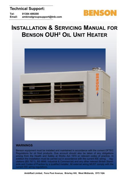
INSTALLATION & SERVICING MANUAL FOR<br />
<strong>BENSON</strong> <strong>OUH²</strong> <strong>OIL</strong> <strong>UNIT</strong> <strong>HEATER</strong><br />
WARNINGS<br />
Benson equipment must be installed and maintained in accordance with the current OFTEC<br />
Regulations for oil fired products. Due account should also be taken of any obligations<br />
arising from the Health and Safety at Works Act 1974 or relevant codes of practice. In<br />
addition the installation must be carried out in accordance with the current IEE wiring regulations<br />
(BS 7671), BS 6896: Industrial & Commercial) and any other relevant British Standards<br />
and Codes of Practice by a qualified installer. All external wiring MUST comply with the<br />
current IEE wiring regulations.<br />
AmbiRad Limited, Fens Pool Avenue, Brierley Hill, West Midlands, DY5 1QA<br />
1
Contents<br />
1 Compliance Notices …………………………………....………..…..…………. 4<br />
1.1 Certificates of Conformity ………………………………..…………..…. 5<br />
1.2 General Product Information …………………………………….…………. 5<br />
1.3 General Requirements ……...……………………………………...………. 5<br />
1.4 Delivery & Pre inspection …………………………………………….…. 6<br />
1.5 Warranty ……………………..…….………………………………………. 6<br />
2 Location & Positioning …………………….………………..…………..…………. 7<br />
2.1 Fuel Supply - General …………..…..……………...………………………. 7<br />
2.2 Fuel ……………...……………………………..……………...……………. 8<br />
2.3 Storage Tank ……………………..…………………….……………….. 8<br />
2.4 Single Pipe System (Gravity Fed) ….…………..………………...………. 9<br />
2.5 Two Pipe System …………………….…………...…………………… 9<br />
2.6 Pressurised Ring Main System ….…………..………………...………. 9<br />
2.7 Pipework and Fittings …………………….…………...…………………… 9<br />
2.8 Electrical Supply ……………...……………………………..………………. 11<br />
2.9 Air Supply ……………………..……………………….……………………. 11<br />
2.10 Warm Air Circulation …………………………………...……...…………. 14<br />
2.11 Flue System …….…………………………...………………..….……. 15<br />
3 Installation …………………………………………………...…….…….…………. 16<br />
3.1 Mounting Heights ………………...……………………...……………. 16<br />
3.2 Heater Mounting …………………………………………………..……...…. 16<br />
3.3 Minimum Clearances ……………………………………...………………. 16<br />
3.4 Flue Installation ……………………………..……..………….……...……. 16<br />
3.5 Oil Installation & Connection ….……………..……………..……...………. 17<br />
3.6 Electrical Installation & Connection ….……………………..……...………. 17<br />
3.7 Heater Control Installation ……………………………….………………. 17<br />
4 Commissioning ……………..…………………………...…………….…….……. 18<br />
4.1 Pre test …………………………………………………...…..…..………. 18<br />
4.2 Ignition ……………………………………………………….…..………. 18<br />
4.3 Air Delivery System …………………………………....…...…..….……. 20<br />
4.4 Hand Over …………………………………………………...….…...………. 20<br />
5 Servicing …………………………………………………...…………..…………. 21<br />
5.1 Planned Servicing …………………………………....………..………. 21<br />
5.2 Servicing procedure Major Components ….……………………...………. 21<br />
5.3 Service Re commissioning ….…………………………………...………. 23<br />
6 Fault Diagnosis By Flow Chart ………….………………...…….……...……. 24<br />
7 Wiring Diagrams ……………………………………………………...……………. 27<br />
8 Technical Data …………………………………………………...………………. 35<br />
8.1 Reference Documents Standards & Codes of Practice ...……...…… 36<br />
9 Parts Listing …………………………………...………………..……………………. 37<br />
10 Dimensional Drawings ………………………………….………...………………. 35<br />
2
~ C O N T E N T S ~<br />
11 User Instructions …………………………………………………………...………. 40<br />
11.1 Commissioning/hand over ……………………………….……….……... 40<br />
11.2 Servicing ……………………………….…………………………..…….… 40<br />
11.3 Start up procedure ……………………………….…………….….……. 40<br />
S E C T I O N 1<br />
11.4 Stop procedure ……………………………….……………………………. 40<br />
11.5 Shutdown procedure ……………………………….……………...……... 40<br />
1.011.6 Compliance Ventilation Notices only ……………………………….…………………..….…..... 4<br />
40<br />
1.111.7 Certificates Lockout of Conformity situations ……………………………….…...………..………. 5<br />
40<br />
1.2 General Product Information 5<br />
1.3 General Requirements 5<br />
Illustrations<br />
1.4 Delivery & Pre-installation Checks 6<br />
1.51 Warranty Oil Systems ………………………………………………………...……………. 6<br />
10<br />
2 Turbulator positions …………….…………………………………………………. 23<br />
2.0 Location & Positioning 7<br />
2.1 Gas Supply 9<br />
Any reference made to Laws, Standards, Directives, Codes of Practice or other<br />
2.2 Electrical Supply 9<br />
recommendations governing the application and installation of heating appliances and<br />
which 2.3 Air may Supply be referred to in Brochures, Specifications, Quotations, 9 and Installation,<br />
Operation 2.4 Minimum and Space Maintenance Requirements manuals is done so for information and 12 guidance purposes only<br />
2.5 and Air should Distribution only be considered System valid at the time of the publication. 12 Benson Heating cannot<br />
2.6 be held Flue responsible System from any matters arising from the revision 13 to or introduction of new<br />
2.7 Laws, Flue Standards, Installation Directives, Codes of Practice or other recommendations. 13<br />
3.0 Installation 16<br />
3.1 Bio Packaging fuel statement. & Siting 16<br />
3.2 Flooring 16<br />
3.3 All our Minimum oil fired Clearances heater products are configured for<br />
16<br />
3.4 use Assembly on both Class D light distillate fuel oil.<br />
16<br />
3.5 Gas Installation and Connection 17<br />
3.6 As a Electrical result of recent Installation changes & Connection made to European<br />
17<br />
3.7 legislation Air Distribution regarding Installation the specification of class D<br />
17<br />
3.8 heating Warm oil Air to Registers allow for the inclusion of 7% FAME<br />
17<br />
3.9 (Fatty Heater Acid Control Methyl Installation Ester) i.e. bio fuel and<br />
18<br />
effective from early 2011, all oil fired air heater<br />
4.0<br />
products<br />
Commissioning<br />
and installations maybe affected.<br />
18<br />
4.1 Pre-Test 18<br />
From April 2011 all our oil fired unit heaters<br />
4.2<br />
will<br />
Ignition<br />
be fitted with Riello burners which are bio<br />
19<br />
4.3 fuel Air compatible Delivery for System blends up to 10%.<br />
21<br />
4.4 Hand Over 21<br />
Please note that the use of bio fuels may give rise<br />
5.0 to a Servicing number of installation issues, to both new<br />
22<br />
5.1 and Planned existing plant Servicing which could affect the warranty<br />
22<br />
5.2 of the Servicing burner. We Procedure recommend - Major that Component you familiarise Parts 22<br />
5.3 yourself Servicing with current - Re-commissioning information from both the<br />
25<br />
6.0 burner Fault manufacturer Diagnosis Riello By Flow and OFTEC. Charts 26<br />
7.0 Wiring Diagrams by Model and Burner Type 28<br />
8.0 Technical Data Net Efficiency Calculations 35<br />
8.1 Benson Cabinet Range Data 36<br />
9.0 Reference Documents Standards, Codes of Practice 39<br />
9.1 Parts Listing 40<br />
3
1.0 Compliance notices<br />
The following information is relevant to the<br />
Benson Oil Fired Unit Heater range (OUHA)<br />
and (OUHC) manufactured by Benson<br />
Heating. These heaters are manufactured<br />
within a strictly controlled quality<br />
environment within the parameters of ISO<br />
9001.<br />
The Benson OUHA (C) has been tested and<br />
assessed for compliance with the following<br />
European Directives.<br />
Machinery Directive: (2006/42/EC)<br />
Low Voltage Directive: (2006/95/EC)<br />
Electromagnetic Compatibility Directive:<br />
(2004/108/EC)<br />
Product Liability Directive: (85/374/EEC)<br />
The manufacturer has taken reasonable and<br />
practical steps to ensure that Benson Unit<br />
Heaters are safe and without risk when<br />
properly used. These heaters should<br />
therefore only be used in the manner and<br />
purpose for which they were intended, and<br />
in accordance with the recommendations<br />
detailed herewith.<br />
The heaters have been designed,<br />
manufactured, assembled, inspected, and<br />
tested, with safety and quality in mind, there<br />
are certain basic precautions which the<br />
installer and user should be aware of, and<br />
they are strongly advised to read the<br />
appropriate sections of the information pack<br />
accompanying the heater, prior to<br />
installation or use.<br />
Benson Heating supports all new products<br />
being supplied to their customers with a<br />
comprehensive information pack; this clearly<br />
defines mandatory instructions for the safe<br />
installation, use, and maintenance, of the<br />
appliance (s).<br />
Where proprietary items are incorporated<br />
into Benson Heating products, detailed<br />
information and instructions are also<br />
provided as part of the information pack.<br />
It is the responsibility of the installer, owner,<br />
user, or hirer, of such products supplied by<br />
Benson Heating, to ensure that they are<br />
familiar with the appropriate information/<br />
manuals, supplied by the manufacturer, and<br />
that they are suitably aware of the purpose<br />
of the manuals and the safety instructions.<br />
In addition, operators must be suitably<br />
trained in the use of the appliance so as to<br />
ensure its continued safe and efficient use.<br />
Benson Heating has a commitment to<br />
continuous improvement, and therefore<br />
reserves the right to amend or change the<br />
specification of the Unit Heater range<br />
subject to compliance with the appropriate<br />
European, National, and Local regulations.<br />
Contained within the text of the manual, the<br />
words 'Caution' and 'Warning' are used to<br />
highlight certain points.<br />
Caution is used when failure to follow or<br />
implement the instruction (s) can lead to<br />
premature failure or damage to the heater or<br />
its component parts.<br />
Warning is used when failure to heed or<br />
implement the instruction (s) can lead to not<br />
only component damage, but also to a<br />
hazardous situation being created where<br />
there is a risk of personal injury.<br />
The Benson OUHA(C) Range conform to<br />
the following harmonized standards:<br />
BS EN 292-1<br />
Safety of Machinery - Basic Concepts,<br />
General Principles for Design Basic<br />
terminology, methodology<br />
BS EN 292-2<br />
Safety of Machinery - Basic Concepts,<br />
General Principles for Design Technical<br />
Principles and Specifications<br />
BS EN 60204-1<br />
Safety of Machinery - Electrical Equipment<br />
for Machines Specification for General<br />
Requirements<br />
BS EN 60335-1<br />
Safety of Household and Similar Electrical<br />
Appliances General Requirements<br />
BS EN 55014<br />
Limits and methods of measurement of radio<br />
disturbance characteristics of electrical<br />
motor-operated and thermal appliances for<br />
4
household and similar purposes, electrical<br />
tools and similar electric apparatus<br />
BS EN 50165<br />
Electrical Equipment of non-electric heating<br />
appliances for household and similar<br />
purposes, safety requirements<br />
1.1 Certificates of conformity<br />
Certificates are available from the Quality<br />
Control Department at Benson Heating.<br />
1.2 General product information<br />
The Benson OUH unit heater models have<br />
an output range from 100,000 Btu to<br />
350,000 Btu. Each heater must be<br />
connected to its own individual open flue.<br />
Each heater is fitted with a forced draught<br />
burner which has been test fired and pre-set<br />
prior to despatch. The safety functions of the<br />
burner are by way of a fully sequential<br />
control box fitted to the burner.<br />
Note<br />
Neither asbestos nor soft soldered joints are<br />
used in the construction or manufacture of<br />
the Benson range of Unit Heaters. The<br />
materials selected for use can withstand the<br />
mechanical, chemical, and thermal stresses<br />
which they will be subject to during foreseen<br />
normal use when installed in accordance<br />
with the manufacturers recommendations.<br />
1.3 General requirements<br />
Caution<br />
Ensure that the fuel supply is in accordance<br />
with the manufacturer's recommendations<br />
and is as stated on the appliance data plate.<br />
Installation, commissioning, and<br />
servicing must only be carried out by<br />
appropriately qualified and competent<br />
persons.<br />
Warning<br />
contrary to the manufacturers<br />
recommendations may constitute a hazard.<br />
Note<br />
To ignore the warning and caution notices,<br />
and to ignore the advice from the<br />
manufacturer on installation, commissioning,<br />
servicing, or use, will jeopardise any<br />
applicable warranty, moreover, such a<br />
situation could also compromise the safe<br />
and efficient running of the appliance itself,<br />
and thereby constitute a hazard.<br />
The installation of the appliance must meet<br />
all the relevant European, national, and local<br />
criteria. (See sections 3 and 9).<br />
Prior to installation the following points<br />
should be considered;<br />
a) The position of the heater for the optimum<br />
efficient distribution and circulation of warm<br />
air.<br />
b) The position of the heater relative to the<br />
route of the flue.<br />
c) The position of the heater relative to the<br />
supply of fuel.<br />
d) The position of the heater relative to the<br />
electrical services, and if appropriate, any<br />
additional controls.<br />
e) The position of the heater relative to the<br />
supply of fresh air.<br />
f) The position of the heater relative to<br />
service and maintenance requirements.<br />
Caution<br />
The heater must not be installed within an<br />
area where the conditions are unsuitable,<br />
e.g. where the atmosphere is highly<br />
corrosive, has a high degree of salinity, or<br />
where high wind velocities may affect burner<br />
operation. Suitable protection should be<br />
provided for the appliance when it is located<br />
in a position where it may be susceptible to<br />
external mechanical damage from; for<br />
example, fork lift trucks, overhead cranes<br />
etc.<br />
Unauthorised modifications to the appliance,<br />
or departure from the manufacturers<br />
guidance on intended use, or, installation<br />
5
1.4 Delivery and pre-installation<br />
checks<br />
The heater is supplied wrapped in heavy<br />
duty protective polythene. On receipt of the<br />
heater, the following checks should be<br />
carried out;<br />
a) The model is as per order<br />
b) That it is undamaged<br />
c) That it is suitable for the fuel supply<br />
d) That it is suitable for the electrical supply<br />
If any of these points are not satisfied then<br />
contact should be made with the Sales<br />
Office at Benson Heating as soon as<br />
possible by Telephoning 01384 489200. In<br />
the case of claims for damage, this must be<br />
signed for as damaged and be reported in<br />
writing within 24 hours of delivery, in order to<br />
comply with insurance criteria.<br />
1.5 Warranty<br />
The heater is supplied with a 1 year parts<br />
and labour warranty and a further year on all<br />
parts excluding consumable’ s.<br />
In addition to this there is also a 10 year<br />
time related warranty on the combustion<br />
chamber.<br />
The warranty commences from the date of<br />
dispatch from the manufacturer, and is<br />
subject to the terms detailed within the<br />
Benson Heating 'conditions of business'.<br />
Note (i)<br />
The warranty may be invalidated if -<br />
a) The installation is not in accordance with<br />
the general requirements of this manual.<br />
b) The flue arrangement and air supply for<br />
the heater are not in accordance with the<br />
manufacturers recommendations, codes of<br />
practice, or similar standards.<br />
c) Air flow through the heater is not in<br />
accordance with the manufacturers technical<br />
specifications.<br />
d) Internal wiring on the heater has been<br />
tampered with or unauthorised service/<br />
repairs undertaken.<br />
e) The main electrical supply input to the<br />
heater has been interrupted during the<br />
heating mode.<br />
f) The heater has been subject to and<br />
affected by the ingress of water in any form.<br />
g) The heater is not operated at the rating(s)<br />
laid down in the manufacturers technical<br />
specifications.<br />
h) The heater has not been operated or<br />
used within the normal scope of its intended<br />
application.<br />
i) The manufacturer's recommended<br />
minimum service requirements have not<br />
been complied with.<br />
Note (ii)<br />
All warranty claims must contain the<br />
following information to enable processing to<br />
take place;<br />
(1) Heater model.<br />
(2) Heater serial number<br />
(3) Order reference/date of order, together<br />
with full installation details (name and<br />
address)<br />
(4) Details or symptoms of fault<br />
(5) Installers name and address.<br />
Faulty parts must be returned to the Benson<br />
Spares Department, the address of which is<br />
provided at the rear of this manual. Any<br />
such parts will undergo inspection to verify<br />
the claim.<br />
Replacement parts supplied prior to this may<br />
be charged, and a credit supplied upon<br />
subsequent validation of the warranty claim.<br />
Consumable items are specifically not<br />
included within the scope of the warranty.<br />
Note (iii)<br />
Notification is required immediately a fault is<br />
suspected.<br />
The manufacturer will not accept<br />
responsibility for any additional damage that<br />
has been caused, expense incurred, or<br />
consequential loss resulting from any failure<br />
of the heater(s).<br />
6
2.0 Location/positioning<br />
Warning<br />
All of the basic criteria must be satisfied<br />
prior to commencing installation and<br />
commissioning, additionally, the Unit Heater<br />
must be positioned and installed so as to<br />
comply with all the relevant standards and<br />
guide lines (see section 9.0), as well as<br />
meeting National and Local Fire Regulations<br />
and Insurance criteria, especially if it is<br />
proposed that the heater is to be installed<br />
within a special risk area (e.g. proximity to<br />
where petrol engined vehicles are stored or<br />
parked, where cellulose spraying takes<br />
place, where woodworking machinery is<br />
operated, etc,).<br />
Indirect fired heaters must not be located in<br />
hazardous areas, however, it is permissible<br />
for the heater to supply air to such areas.<br />
The heater must not be installed within an<br />
environment where there is a high<br />
concentration of chlorides, fluorides, salts, or<br />
other aggressive or volatile chemicals/<br />
compounds. Nor should the heater be<br />
positioned where high winds or draughts<br />
could adversely affect the burner.<br />
The heater must be installed so that it is<br />
level. Supports for the heater must be<br />
sufficiently robust to withstand the weight of<br />
the heater and any ancillary equipment. Any<br />
combustible material adjacent to the heater<br />
or flue system must be so placed or shielded<br />
so that its surface temperature does not<br />
exceed 65°C<br />
The location chosen for the heater must<br />
allow for the fitting of an effective flue<br />
system.<br />
The location must also allow for adequate<br />
clearance for the air supply, return air<br />
circulation, oil supply, electrical supply,<br />
whilst also providing good and safe working<br />
access.<br />
Suspended free blowing Unit Heaters are at<br />
their most effective when located as close to<br />
the working area as possible. However care<br />
should be exercised to avoid directing the<br />
discharged air directly onto the occupants of<br />
the area to be heated.<br />
Where the passage of cold air causes<br />
problems (e.g by entrances, loading bays<br />
etc) it is considered favourable if the heater<br />
is positioned so as to discharge towards or<br />
across the cold air source from a distance<br />
from 1.5m - 6m dependent upon the size of<br />
the entrance and the air throw<br />
characteristics of the heater.<br />
On exposed walls heaters should be<br />
positioned so as to discharge towards, or<br />
along the length of the exposed wall. In<br />
areas where it is proposed that more than<br />
one heater is to be installed, a general<br />
scheme of circulation should be drawn up<br />
and maintained, thereby offering the best<br />
heat distribution.<br />
Air pressure within the area heated and the<br />
outside air pressure must remain the same,<br />
factors influencing this would be the<br />
presence of extraction systems, ventilation<br />
systems, and various types of process plant.<br />
OUHA 200-350 models can be installed to<br />
allow the fans to work in opposite directions.<br />
This enables the heater to be installed<br />
centrally in the area to be heated and allows<br />
warm air to be discharged to both the front<br />
and rear of the heater.<br />
2.1 Fuel supply - general<br />
The Benson range of oil fired heaters are all<br />
manufactured and pre-set for use with 35<br />
second gas oil delivered to the burner via a<br />
suitable piped system from the oil storage<br />
tank.<br />
Galvanised or plastic pipe work and<br />
fittings must not be used. (see BS 5410<br />
Part 1 1997)<br />
The constraints of the application will, to a<br />
large extent, determine whether it is<br />
preferable to use a single pipe gravity feed<br />
system, or whether the two pipe pumped<br />
system is more appropriate.<br />
Where more than one appliance is to share<br />
a common supply it will be necessary to use<br />
a pressurised ring main system.<br />
7
All pipe work must be constructed and<br />
installed so that it does not permit the<br />
ingress of air.<br />
The construction, size, and position of the oil<br />
storage tank must take account of the<br />
current regulations, as well as suiting the<br />
requirements of the installation.<br />
Caution<br />
On pumped systems always check that the<br />
pump is correctly set up prior to running, and<br />
always ensure that valves are open allowing<br />
a free flow of oil through the system.<br />
2.2 Fuel<br />
In order to promote trouble free operating it<br />
is necessary that the oil within the storage<br />
tank and oil line does not fall below the cold<br />
filter plugging point (cfpp), in this country<br />
and with class D fuel (also referred to as gas<br />
oil). The critical temperature is -4°C for this<br />
summer grade.<br />
The cfpp critical temperature for the winter<br />
grade is -12°C. If summer grade fuel is<br />
stored for winter use in areas prone to<br />
severe frosts and low temperatures it will be<br />
necessary to insulate or even heat the<br />
supply tank and pipe work.<br />
Note<br />
The fuel supplier should be contacted prior<br />
to installation so that any requirements<br />
concerning delivery, transport, storage and<br />
use can be addressed before work<br />
commences.<br />
Warning<br />
The pump pressure must not exceed a<br />
maximum of 0.4 bar, this is because beyond<br />
this point gas is liberated from the oil.<br />
The heaters are set for single pipe<br />
operation. A bypass plug is provided<br />
separate with the burner for conversion to<br />
two pipe see Riello manual.<br />
2.3 Storage tank<br />
An externally painted steel storage tank to<br />
BS 799 part 5 1987 or a medium density<br />
polyethylene oil tank OFTEC certified to<br />
OFS T-100 may be used. Local, national,<br />
European and fire regulations must also be<br />
complied with and must include:<br />
A fuel level gauge (not made from glass) a<br />
vent pipe with a diameter greater than that<br />
of the filler and featuring a weatherproof<br />
termination.<br />
A sludge valve.<br />
An outlet valve situated at the opposite end<br />
of the tank to the sludge valve.<br />
A filler pipe connection situated at the<br />
opposite end to the outlet valve.<br />
The size of the storage tank must take<br />
account of the estimated consumption and<br />
any quantity price breaks offered by the oil<br />
supplier.<br />
It is preferable to install the tank outside,<br />
however, if this is not practicable and the<br />
tank has to be installed indoors advice must<br />
be sought about its siting, especially so far<br />
as fire regulations are concerned.<br />
If a separate fire resistant chamber cannot<br />
be provided for indoor installations, a<br />
catchment pit with a capacity ten percent<br />
greater than that of the storage tank must be<br />
provided<br />
Storage tanks can if necessary be sited on a<br />
roof, but this is subject to special regulations<br />
as well as local authority approval and<br />
compliance with fire regulations, reference<br />
to BS 5410 part 2 1978 & part 1 1997 is<br />
strongly suggested.<br />
It is advisable to leave the tank unpainted on<br />
the inside, but to paint the outside with a<br />
proprietary grade of anti-corrosive paint.<br />
A galvanised or open topped tank is strictly<br />
not allowed.<br />
All oil storage tanks require a bund<br />
The Control of Pollution Regulation (Oil<br />
Storage) 2001 should be consulted prior to<br />
installation.<br />
8
2.4 Single pipe system (gravity feed)<br />
For installations where the oil tank is 200mm<br />
or more above the level of the fuel pump the<br />
principle of gravity feed may be used.<br />
The draw off point for the supply to the<br />
burner must not be positioned any lower<br />
than 100mm above the bottom of the tank.<br />
Where a return valve is fitted this must be<br />
tamper proof to prevent inadvertent<br />
operation.<br />
Caution<br />
If the valve is closed when the pump is<br />
running the oil pressure can be increased<br />
sufficiently so as to cause damage to the<br />
seals within the pump.<br />
The return oil should preferably be<br />
discharged through an elbow onto a tank<br />
plate situated within the tank, this should be<br />
positioned so as not to introduce air or air<br />
bubbles into the draw off pipe.<br />
2.5 Two pipe system<br />
This is used where the oil storage tank is<br />
lower than the pump.<br />
Access for the fuel feed to the burner should<br />
be via a suitable tapping made in the top of<br />
the tank, and the fuel feed pipe should<br />
extend to not less than 100mm above the<br />
bottom of the tank.<br />
A none return valve with a metal to metal<br />
seat should be fitted, especially if the return<br />
pipe work is terminated at a level above the<br />
draw off tube. The non- return valve must be<br />
removable for service and maintenance<br />
purposes, and the return pipe from the<br />
pump must therefore be extended down into<br />
the tank to the same level as the suction<br />
pipe.<br />
The presence of a tamper proof isolating<br />
valve fitted within the return pipe is only<br />
required if there is a risk that oil will siphon<br />
out of the tank if the return pipe is<br />
disconnected at the pump during<br />
maintenance or servicing and if the none<br />
return valve has been omitted.<br />
Caution<br />
The Deareator must be fitted the burner<br />
side of the inlet fuel filter<br />
Maximum lift should not exceed 3.5 metres,<br />
and the vacuum should not exceed 0.4 bar.<br />
Each heater must have a separate fuel<br />
supply.<br />
Note<br />
It is strongly recommended that the separate<br />
manual concerning the operational details of<br />
the burner supplied with the heater as part<br />
of the information package is studied prior to<br />
installation.<br />
2.6 Pressurised ring main system<br />
This system is used to supply a number of<br />
units from a common storage tank.<br />
A booster pump is used to provide the<br />
pressure to push the oil around the ring<br />
main and back to the tank.<br />
Pressure reducing valves should be fitted on<br />
the delivery pipe to each heater to ensure<br />
that the pressure at the burner pump is less<br />
than 6 psi.<br />
Caution<br />
The internal by-pass plug must be removed<br />
from the burner pump when used in a<br />
pressurised ring main application.<br />
2.7 Pipe work and fittings<br />
Caution<br />
Galvanised or plastic pipe work and<br />
fittings must not be used. (see BS 5410<br />
Part 1 1997)<br />
All joints must be sealed properly, if<br />
necessary using PTFE tape or other<br />
approved sealing media.<br />
The pipe work must be effectively sealed so<br />
as to prevent the ingress of air.<br />
It is advisable to check all pipe work prior to<br />
installation to ensure that there is no loose<br />
debris or scale present.<br />
9
Typical Fuel Layout<br />
H<br />
Maximum<br />
4 metres<br />
H<br />
m<br />
0<br />
0.5<br />
1.0<br />
1.5<br />
2.0<br />
3.0<br />
3.5<br />
I.D.<br />
8mm<br />
35.0<br />
30.0<br />
25.0<br />
20.0<br />
15.0<br />
8.0<br />
6.0<br />
I.D.<br />
10mm<br />
100.0<br />
100.0<br />
100.0<br />
90.0<br />
70.0<br />
30.0<br />
20.0<br />
BURNER<br />
The pump suction should not exceed a maximum of 4 metres.<br />
Beyond this limit gas is released from t he oil.<br />
H<br />
The return line should terminate within the oil tank at the same level<br />
as the suction line; in this case a non return valve is not required.<br />
Should, however, the return line terminate over the fuel level,<br />
a non return valve is essential.<br />
This solution, however, is less safe than the previous one, due to<br />
possibility of leakage of the valve.<br />
Priming the pump: Start the burner and await priming.<br />
Should lock-out occur prior to arrival of the fuel, wait at least 20 seconds<br />
before repeating the operation.<br />
BURNER<br />
The pump suction must not exceed 4 metres;<br />
beyond this value the pump becomes noisy.<br />
H<br />
The return valve must termin ate at the same level<br />
as the foot valve, otherwise the pump may<br />
become air locked.<br />
1 GATE VALVE<br />
2 IN-LINE FILTER<br />
3 PUMP<br />
4 RELIEF VALVE<br />
5 PRESSURE GAUGE<br />
6 PRESSURE REDUCING VALVE<br />
7 RETURN TO TANK<br />
7<br />
4 5<br />
6 6<br />
3<br />
1 2<br />
10
Black iron pipes can be hammered to assist<br />
in the removal of these contaminants.<br />
Note<br />
The oil feed to each heater must be fitted<br />
with a fire check valve and isolating valve.<br />
The fire check valve must be operated by<br />
way of a fusible link positioned so that it is<br />
above the burner.<br />
Note<br />
Any waste oil or sludge must be<br />
disposed of correctly.<br />
Never dispose of it by dumping or<br />
tipping it down drains or into<br />
watercourses where ground water can<br />
become polluted and environmental<br />
damage caused.<br />
2.8 Electrical supply<br />
Wiring external to the unit heater must be<br />
installed in accordance with any local,<br />
national, and European regulations, as well<br />
as meeting the appropriate requirements of<br />
IEE regulations.<br />
The means of connection to the main<br />
electrical supply must allow for complete<br />
electrical isolation of the heater, furthermore,<br />
in the case of a unit wired for a three phase<br />
supply, the supply should only be used to<br />
serve the heater itself and no other plant or<br />
equipment. The position of the isolation<br />
switch must be such that it is adjacent to the<br />
heater and easily accessible at all times. In<br />
addition, the isolator itself must have a<br />
contact separation of not less than 3mm.(as<br />
per BS5991 clause 20.2).<br />
All connections must be checked to ensure<br />
that they are secure, and free from<br />
corrosion.<br />
Terminals and connections should also be<br />
checked to ensure that no stray strands are<br />
bridging terminals.<br />
Electrical continuity should also be checked.<br />
Cables, conduit, and fittings that are used to<br />
make the connection between the isolator<br />
and the heater must conform to the<br />
appropriate IEE regulations.<br />
All heaters are supplied fused and prewired,<br />
all must be earthed.<br />
The Control fuse ratings are detailed on the<br />
appliance data plate.<br />
Warning<br />
Ensure that the electric and oil supplies are<br />
turned off before any electrical work is<br />
carried out on the heater.<br />
Ensure that wiring cannot make contact with<br />
any surfaces liable to be subject to high<br />
temperatures or where the insulation of the<br />
wiring could be impaired as a result of such<br />
contact.<br />
Final connections for any additional external<br />
controls must be completed on site, and<br />
must be carried out according to IEE<br />
regulations.<br />
Separate user information is provided for the<br />
time control unit and the burner, and forms<br />
part of the product information pack which<br />
accompanies every heater when<br />
despatched.<br />
Caution<br />
The main electrical supply must not be<br />
switched off or disconnected as a method<br />
for stopping the heater, the exception to this<br />
is in an emergency, or during servicing,<br />
when the heat exchanger has been allowed<br />
to cool sufficiently to prevent any damage<br />
from occurring. Claims for damage will not<br />
be considered if they have resulted from<br />
incorrect wiring or the incorrect use of the<br />
heater.<br />
Always ensure that the appropriate<br />
personal protective equipment is used.<br />
2.9 Air Supply<br />
Provision must be made for the existence of<br />
an air supply in order to satisfy both<br />
combustion and ventilation criteria.<br />
It is a requirement that the area where the<br />
air heater is located must have a permanent<br />
11
air vent of negligible resistance direct to the<br />
outside air.<br />
Such air vents must be positioned so as not<br />
to become blocked or flooded, nor should<br />
they be placed so as to introduce<br />
undesirable matter (e.g. flammable, volatile,<br />
or aggressive chemicals/compounds or<br />
potentially hazardous or harmful<br />
substances) either direct from the outside, or<br />
through their proximity to an adjacent<br />
extraction system.<br />
Note It is strongly recommended that BS<br />
6230 is referred to for further information<br />
concerning ventilation requirements<br />
Where mechanical ventilation is used it is a<br />
requirement that the inlet is of the<br />
mechanical type, and the outlet is either<br />
mechanical or natural.<br />
2.9.1 Heaters installed within the<br />
heated space.<br />
Where heaters are installed within the space<br />
to be heated (i.e. not a plant room or<br />
enclosure) then:<br />
Combustion air or heater related ventilation<br />
air will not be required if -<br />
• The design air change rate of the<br />
heated space is 0.5 air changes per<br />
hour or greater or<br />
• The design air change rate may be<br />
satisfied by natural infiltration or by<br />
mechanical ventilation<br />
Combustion and General ventilation will be<br />
required if -<br />
• The design air change rate of the<br />
heated space is less than 0.5 air<br />
changes per hour or<br />
• Where the heated space has an air<br />
change rate of less than 0.5 air<br />
changes per hour then it will be<br />
necessary to provide either natural<br />
ventilation openings to the heated<br />
space (section 2.9.1.1 refers) or the<br />
mechanical ventilation of the heated<br />
space (section 2.9.1.2. refers)<br />
2.9.1.1 Natural Ventilation Openings<br />
to the Heated Space.<br />
If the heated space design air change rate is<br />
less than 0.5 air changes per hour then<br />
provision for low level natural ventilation<br />
openings will only be necessary.<br />
The minimum free area of the low level<br />
natural ventilation opening shall be:<br />
• 2cm 2 for each kW of rated heat input<br />
The low level natural ventilation opening<br />
should be situated on an external wall and<br />
be within 1000 mm of floor level for natural<br />
gas and ideally at floor level for l.p.g gas<br />
installations but in any event no higher than<br />
250 mm.<br />
The table in the next column provides<br />
specific data for each heater model as -<br />
Model<br />
Minimum Free Area of<br />
ventilation opening<br />
High Level<br />
Low Level<br />
cm 2 cm 2<br />
100 None 68<br />
140 None 88<br />
200 None 128<br />
250 None 166<br />
300 None 192<br />
350 None 230<br />
2.9.1.2 Mechanical Ventilation to the<br />
Heated Space.<br />
In the event that the heated space has a<br />
design air change of less than 0.5 air<br />
changes per hour and that installer prefers<br />
to mechanically ventilate the heated space<br />
rather than provide ventilation openings then<br />
-<br />
• The heated space needs to be<br />
mechanically ventilated so that the<br />
design air change is 0.5 air changes or<br />
greater.<br />
12
• It is a requirement that the mechanical<br />
ventilation shall be of the ‘input’ type<br />
with either natural or mechanical<br />
extraction.<br />
• Systems of mechanical extraction with<br />
a natural inlet shall not be used.<br />
• It is necessary to provide an automatic<br />
means to safely inhibit heater(s)<br />
operation should mechanical air<br />
supply fail for any reason.<br />
2.9.2. Heaters Installed within a Plant<br />
Room or Enclosure.<br />
A plant room means a room housing the<br />
heater plant and probably other items of<br />
building service plant and would generally<br />
have generous space for maintenance.<br />
An enclosure is where the heater is installed<br />
within a compartment or confined area<br />
where space is limited.<br />
Where heaters are installed within a plant<br />
room or enclosure then provision for both<br />
combustion air and air for general ventilation<br />
will be required by means of high and low<br />
level ventilation openings (sections 2.3.2.1<br />
refers to plant room applications and<br />
sections 2.3.2.2 refers to enclosure<br />
applications).<br />
Alternatively the plant room or enclosure<br />
may be mechanically ventilated (section<br />
2.3.2.3 refers).<br />
2.9.2.1 Natural Ventilation Openings<br />
to Plant Rooms<br />
For plant room applications the minimum<br />
free area of ventilation opening shall be:<br />
• At high level 2 cm 2 for each kW of<br />
rated heat input.<br />
• At low level 4 cm 2 for each kW of rated<br />
heat input.<br />
The high level ventilation opening should be<br />
sited on an external wall and positioned as<br />
high as is practical and always within the top<br />
15% of the wall height.<br />
The low level natural ventilation opening<br />
should be situated on an external wall and<br />
be within 1000 mm of floor level for natural<br />
gas and ideally at floor level for l.p.g gas<br />
installations but in any event no higher than<br />
250 mm.<br />
The table below provides specific data for<br />
each heater model as -<br />
Model<br />
Minimum Free Area of<br />
ventilation opening<br />
High Level<br />
Low Level<br />
cm 2 cm 2<br />
100 68 134<br />
140 88 176<br />
200 128 258<br />
250 166 332<br />
300 192 384<br />
350 230 460<br />
2.9.2.2 Natural Ventilation Openings<br />
to Enclosures<br />
For enclosure applications the minimum free<br />
area of ventilation opening shall be:<br />
• At high level 5 cm 2 for each kW of<br />
rated heat input.<br />
• At low level 10 cm 2 for each kW of<br />
rated heat input.<br />
The high level ventilation opening should be<br />
sited on an external wall and positioned as<br />
high as is practical and always within the top<br />
15% of the wall height<br />
The low level natural ventilation opening<br />
should be situated on an external wall and<br />
be within 1000 mm of floor level for natural<br />
gas and ideally at floor level for l.p.g gas<br />
installations but in any event no higher than<br />
250 mm.<br />
The table in the next column provides<br />
specific data for each heater model as -<br />
13
Model<br />
Minimum Free Area of<br />
ventilation opening<br />
High Level<br />
Low Level<br />
MODEL<br />
Mechanical<br />
Ventilation Rate for<br />
Plant Room or<br />
Enclosure<br />
cm 2 cm 2<br />
M 3 /h<br />
100 170 340<br />
140 220 440<br />
200 320 640<br />
250 415 830<br />
300 480 960<br />
350 575 1150<br />
100 141<br />
140 182<br />
200 265<br />
250 344<br />
300 397<br />
350 476<br />
2.9.2.3 Mechanical Ventilation to a<br />
Plant Room or Enclosure.<br />
In the event that the installer prefers to<br />
mechanically ventilate the plant room or<br />
enclosure rather than provide ventilation<br />
openings then -<br />
• The plant room or enclosure needs to<br />
be mechanically ventilated at the rate<br />
of 4.14 m 3 /h of fresh air per kW or<br />
rated heat input.<br />
• It is a requirement that the mechanical<br />
ventilation shall be of the ’input’ type<br />
with either natural or mechanical<br />
extraction. Where mechanical<br />
extraction is selected then the<br />
extraction rate should be 5%-10% less<br />
than the input rate.<br />
• Systems of mechanical extraction with<br />
a natural inlet shall not be used.<br />
• It is necessary to provide an automatic<br />
means to safely inhibit heater(s)<br />
operation should mechanical air<br />
supply fail for any reason.<br />
2.10 Warm Air Circulation<br />
The air heater should be positioned to<br />
enable maximum circulation of discharged<br />
warm air within the area to be heated, whilst<br />
taking account of personnel within the area,<br />
sources of cold air ingress, and obstructions.<br />
Ensure louvres are adjusted outwards<br />
and ensure blades are not resonating<br />
The air temperature rise on passing the heat<br />
exchanger is typically around 340°C<br />
A full and unobstructed return air path to the<br />
air heater must be provided (see 2.9 Air<br />
Supply).<br />
Where the heater is positioned to deliver<br />
blown air through an opening in a wall,<br />
return air intakes should be located so that<br />
they cannot become blocked. Similarly these<br />
intakes must be positioned so as not to draw<br />
in odours, fumes, hazardous vapours or<br />
particles.<br />
The table opposite provides specific data for<br />
each heater model as -<br />
14
2.11 Flue system.<br />
Warning<br />
It is essential that the products of<br />
combustion are flued to the outside of the<br />
building. Each heater must have its own<br />
separate flue, with a flue diameter of not<br />
less than is detailed in this manual.<br />
The minimum vertical length of flue must not<br />
be less than 1m. The number of bends<br />
should be kept to a minimum.<br />
It is strongly advised that BS 5854; 1980,<br />
and BS 5440; parts 1 and 2, are used as<br />
consultative documents when considering<br />
flue requirements.<br />
Care should be taken to ensure that the flue<br />
terminal is not situated in a high-pressure<br />
area, the proximity of buildings and other<br />
obstacles which will influence this must be<br />
taken into account, preferably at the design<br />
stage.<br />
Provision must be made for the<br />
disconnection of the flue for inspection and<br />
service requirements, and it is strongly<br />
advised that where bends are fitted<br />
inspection covers are included.<br />
Flue should be supported at intervals not<br />
exceeding 1.8 mtrs<br />
The materials from which the flue is<br />
constructed must be non-combustible,<br />
resistant to internal and external corrosion,<br />
and be capable of withstanding the stresses<br />
and loadings associated with normal use.<br />
When designing the flue system the<br />
prevention of the formation and entrapment<br />
of condensation must be a key<br />
consideration.<br />
Twin wall or insulated systems are<br />
recommended, as they tend to inhibit the<br />
formation of condensates.<br />
The condensate pipe from the flue to the<br />
disposal point must be made from corrosion<br />
resistant pipe of not less than the internal<br />
diameter of the drain pipe.<br />
If the flue passes through a wall, ceiling, or<br />
roof made from combustible material then it<br />
has to be sleeved so as to provide a<br />
minimum of a 25mm void between the<br />
exterior of the flue and the internal wall of<br />
the sleeve. The maximum permitted<br />
temperature of any adjacent combustible<br />
material is 65°C.<br />
The position of the flue and its terminal<br />
should be such that it does not impair the<br />
combustion process. It should terminate in<br />
an exposed position so as to allow the<br />
escape and dissipation of flue gases without<br />
risk of their re-entering the property through<br />
windows, ventilation ports, etc.<br />
The flue should extend to at least 1m above<br />
the height of any object within 3.5m of the<br />
terminal.<br />
Flue terminals should be fitted on all flues,<br />
the terminal must be of the approved type,<br />
and have outlet grilles on all sides giving a<br />
total free area of at least double that of the<br />
flue.<br />
Caution<br />
It is imperative that the flue should be<br />
properly sealed where it passes through the<br />
roof, this can best be achieved by using the<br />
approved method of roof flashing plate and<br />
cravat.<br />
Note<br />
It should be noted that claims made under<br />
warranty and attributed to the ingress of<br />
water may not be considered especially if an<br />
approved method of sealing has not been<br />
used, or if the design of the flue has not<br />
made provision for possible condensation<br />
problems.<br />
Where condensation is unavoidable traps<br />
should be included to encourage the<br />
condensates to flow freely to a point from<br />
which they may be released, preferably into<br />
a gully.<br />
15
3.0 Installation<br />
3.1 Installation Mounting Heights<br />
OUHA models<br />
The Heater must be installed within the<br />
mounting heights indicated below in metres.<br />
The following clearances in mm must be<br />
observed *when suspended:<br />
Model Size<br />
OUHA Min Max<br />
100 2.0 2.7<br />
140 2.0 2.7<br />
200 2.4 3.0<br />
250 2.4 3.5<br />
300 2.5 3.5<br />
350 2.4 3.5<br />
3.2 Heater Mounting<br />
The heater and flue must be adequately<br />
supported by one of the following methods;<br />
a) Suspension by steel drop rods or straps<br />
from the M10 fixing points located on top of<br />
the heater. These must be of sufficient<br />
strength to safely carry the weight of the unit<br />
and ancillary equipment. The straps may<br />
only drop vertically to eyebolts, if used; I.E.<br />
They must not be joined to the eyebolt at an<br />
angle to the vertical, and eyebolts if used<br />
should be of an approved type.<br />
b) OUH heaters can be mounted on<br />
specifically designed cantilever wall or<br />
vertical stanchion brackets which locate<br />
directly to the four M10 fixings on the heater<br />
casing.<br />
Alternatively OUHA or OUHC units can be<br />
mounted on cantilever type wall brackets<br />
however consideration must be given to<br />
ensure that the bracket is large enough to<br />
support the heater whilst providing the<br />
necessary clearances.<br />
In either case the installer should ensure<br />
that the wall wall fixings or other support<br />
medium is capable of supporting the weight<br />
c) On a level non-combustible surface<br />
capable of adequately supporting the weight<br />
of the unit and ancillary equipment .<br />
3.3 Minimum clearances<br />
The following minimum clearances (in<br />
millimeters) are recommended when<br />
installing the heater.<br />
Model<br />
100 140 200 250 300 350<br />
Above 300<br />
Below* 300<br />
RHS 680 810<br />
LHS 250<br />
Rear<br />
OUHA<br />
Rear<br />
OUHC<br />
3.4 Flue Installation<br />
400 560<br />
200<br />
An integral flue spigot is fitted to all unit<br />
Heaters thereby allowing the flue to connect<br />
directly to the heater.<br />
The design of the flue must ensure that it<br />
can be disconnected to allow for cleaning<br />
and servicing, furthermore, all of the flue<br />
section joint sockets must face upwards,<br />
and the seal between the sections achieved<br />
through mechanical joints or through the use<br />
of approved caulking string and grout.<br />
It is strongly advised that BS 5854 and BS<br />
5440 parts 1 and 2 are referred to.<br />
Where condensation is likely to be a<br />
problem provision should be made<br />
preferably at the design stage.<br />
16
3.5 Oil Installation/connection<br />
The oil tank must be positioned so that there<br />
is a fall of 7.5mm (+/- 2.5mm) for every<br />
30mm away from the outlet and towards the<br />
sludge/drain valve, which must be sited at<br />
the lowest point in the tank. If the tank is<br />
positioned on supports then there must be<br />
an adequate protective layer between tank<br />
and support to prevent damage or<br />
deterioration through corrosion. It is strongly<br />
suggested that reference is made to BS<br />
5410 ; part 2 ; 1978.<br />
It is also suggested that the installer is<br />
familiar with the detail and requirements<br />
contained within sections 2.1 through to<br />
section 2.6 of this manual prior to<br />
commencing installation.<br />
Warning<br />
Prolonged exposure and contact with Gas<br />
Oil can result in the natural oils being<br />
removed from the skin, sensitisation can<br />
result in dermatitis.<br />
Always ensure that the appropriate personal<br />
protective equipment is used.<br />
3.6 Electrical Installation/connection<br />
Benson unit heaters are only available in<br />
230V 50Hz 1PH.<br />
must be carried out according to IEE<br />
regulations.<br />
Separate user information is provided for the<br />
time control unit and the burner, and forms<br />
part of the product information pack which<br />
accompanies every heater when<br />
despatched.<br />
Warning<br />
Always isolate from mains electrical supply<br />
before commencing work on the heater.<br />
Always ensure that the appropriate personal<br />
protective equipment is used.<br />
3.7 Heater Control Installation<br />
Warning<br />
Isolate heater from mains before<br />
undertaking any electrical work.<br />
Unless specified all Unit Heaters are<br />
manufactured and supplied with a remote<br />
controllers are available to be wired back to<br />
the heater.<br />
Refer to Controller instruction manual for full<br />
installation details.<br />
See section 7.0 for individual wiring<br />
diagrams.<br />
It is recommended that reference is made to<br />
the wiring diagrams contained within section<br />
7 of this manual prior to installation or<br />
connection to the supply. The electrical<br />
supply must be as specified and suitable for<br />
the heater, and must be run within conduit to<br />
a point adjacent to the heater, and be<br />
terminated to provide an isolation point that<br />
will prevent remote or inadvertent activation.<br />
Cables, conduit, and fittings that are used to<br />
make the connection between the isolator<br />
and the heater must conform to the<br />
appropriate IEE regulations.<br />
All heaters are supplied fused and<br />
-wired, all must be earthed.<br />
pre<br />
Final connections for any additional external<br />
controls must be completed on site, and<br />
17
4.0 Commissioning<br />
Note:<br />
It is a requirement that only suitably<br />
qualified and competent personnel are<br />
allowed to undertake the commissioning<br />
of the heater.<br />
It is also strongly recommended that<br />
prior to commissioning the engineer<br />
familiarises himself with; the information<br />
contained within the information pack<br />
that accompanies the heater, the heater<br />
itself, and with the specific requirements<br />
of the installation/application.<br />
Warning<br />
All Unit Heaters undergo a rigorous test<br />
programme prior to being despatched, whilst<br />
such a programme does involve precommissioning<br />
and setting up the heater to<br />
operate efficiently and well within its<br />
designed operational limits, this does not<br />
mean that on site commissioning is less<br />
important than might otherwise be the case.<br />
The idiosyncrasies of each installation can<br />
only ever be allowed for, through the use of<br />
thorough on site commissioning carried out<br />
by trained and experienced personnel<br />
equipped with the correct tools and<br />
apparatus.<br />
Note<br />
It is strongly recommended that equipment<br />
used for the sampling and analysis of flue<br />
gases is accurate to within +/- 0.1% and<br />
maintained so that it is regularly calibrated.<br />
4.1 Commissioning - Pretest<br />
Check to ensure electrical safety, and<br />
inspect and check the oil installation, testing<br />
for leaks.<br />
(a) Ensure that the electrical supply is turned<br />
off.<br />
(b) Ensure that the oil supply is turned off.<br />
(c) Check that all panels and fasteners are<br />
secure and in place.<br />
(d) Check that the heater is installed<br />
correctly and that the support is adequate.<br />
(e) Ensure that warm air delivery outlets are<br />
open.<br />
(f) Check that fan is free to rotate and the<br />
guards are in place.<br />
(g) Ensure that the flue is secure,<br />
adequately supported, and that the various<br />
joints are properly sealed.<br />
(h) Check that there is provision for flue gas<br />
sampling and that this sample point can be<br />
plugged and sealed after commissioning.<br />
(i) Remove cover from fan limit stat check<br />
that fan limit stat settings have not been<br />
disturbed and are as follows:<br />
Fan Control: Fan on 50°C Fan off 30 ° C<br />
Overheat limit: set at 100°C<br />
Also check that the white button (automatic)<br />
is pulled outward and that the red button<br />
(reset) is pushed inwards to the reset<br />
position.<br />
(j) Ensure that the burner is securely<br />
attached to the heater.<br />
(k) Test for electrical earth continuity<br />
between the heater, oil pipe work, and<br />
mains supply.<br />
(l) Turn on main electrical supply.<br />
(m) Enable fan on via controller by selecting<br />
‘Fan only’; ‘Vent only’; ‘Vent/Manual’.*<br />
(* dependent on control type supplied. Refer<br />
to individual controller operating manual.)<br />
(n) Check to ensure burner is off but power<br />
remains to the fan. The fan will start<br />
enabling fan direction etc to be verified.<br />
Reset Fan on/standby switch to off.<br />
(o) Set room thermostat and time clock to<br />
'demand' positions.<br />
(p) Turn mains electrical supply to off,<br />
replace and secure lower louvered panel<br />
covering fan and motor assembly.<br />
4.2 Commissioning - Ignition<br />
Note<br />
It is strongly recommended that the separate<br />
manual concerning the operational details of<br />
the burner supplied with the heater as part<br />
of the information package is studied prior to<br />
commissioning.<br />
Time intervals within the ignition sequence<br />
will vary slightly from one model to another.<br />
18
Warning<br />
Do not proceed with commissioning unless<br />
all the criteria detailed have been satisfied.<br />
(a) Ensure the electrical supply is turned off.<br />
(b) Ensure that the Oil supply is turned off.<br />
(c) Turn on main electrical supply.<br />
(d) Enable burner via controller by selecting<br />
‘Heat’ (Relay 2); ‘Heat On’; ‘Heat/Auto’. *<br />
(* dependent on control type supplied. Refer<br />
to individual controller operating manual.)<br />
(e) Select 'on' position for heater on/standby<br />
switch.<br />
(f) Check for the following burner sequence<br />
1 15s Pilot ignition... Burner ignition...<br />
4 ambient) and the burner automatically refires.<br />
(o) Re-set time clock to a minimum off<br />
period, checking that the burner shuts down,<br />
and then automatically re-lights once the<br />
minimum off period has elapsed (Separate<br />
information on the time clock is contained<br />
within the information package supplied with<br />
the heater).<br />
(p) Check limit stat by isolating fan control<br />
circuit<br />
The time between the fan stopping and<br />
burner shut down should be noted.<br />
If the time interval between fan stop and<br />
burner shut down is greater than 2 minutes<br />
Check settings on fan and limit stat are<br />
correct.<br />
(q) Undertake flue gas analysis using<br />
approved and calibrated analysing<br />
equipment recording data on the<br />
commissioning card, ie, CO, CO 2 , net and<br />
gross flue temperatures.<br />
Record burner oil pump pressure, ambient<br />
temperature, barometric pressure, and<br />
smoke reading (0 - 1 Baccarach scale).<br />
Note (i)<br />
The burner air and oil pressure settings<br />
should be only very finely adjusted to<br />
achieve a CO 2 reading of 12.5% (+/- 0.5%).<br />
Note (ii)<br />
The gross efficiency must be approximately<br />
80 % sample taken at 1m above the flue<br />
spigot point.<br />
Note (iii)<br />
All Unit Heaters are test fired and precommissioned<br />
as part of the manufacturing<br />
process, if however, during on site<br />
commissioning the data are found to be not<br />
in accordance with the manufacturers data,<br />
then the following action is recommended.<br />
* Re-check all readings and calculations.<br />
* Adjust burner as per manufacturers<br />
instructions.<br />
* Consult Benson Heating Technical<br />
Department.<br />
19
(r) Complete commissioning card and<br />
provide operating instructions for the user,<br />
high-light the fact that the manufacturer<br />
recommends that in the interests of safety<br />
and efficiency the heater is serviced on a<br />
regular basis only by qualified and<br />
competent persons.<br />
The completed commissioning card must be<br />
returned to Benson Heating Service<br />
Department immediately after the<br />
satisfactory completion of commissioning,<br />
failure to do so can invalidate any<br />
subsequent warranty claim.<br />
(s) Set all controls to the requirements of the<br />
user.<br />
(t) Final adjustment for the direction of the<br />
air flow from the heater should be made.<br />
4.3 Commissioning - air delivery<br />
system<br />
Final adjustment of the air louvres are<br />
adjusted outwards and ensure blades are<br />
not resonating.<br />
Caution<br />
On ducted applications it is necessary that<br />
the system is balanced in order to optimise<br />
the efficiency of the heater and the air<br />
distribution and delivery system Failure to<br />
balance the system can result in fan motor<br />
overloading and premature component<br />
failure, it can also result in an inefficient<br />
heating/ventilation system.<br />
(a) Check that the amount of fan produced<br />
air volume is in accordance with the heater<br />
specification, if the volume is too great the<br />
fan can be overloaded. Ensure that the<br />
running current is as per that stated on the<br />
heater data plate.<br />
Alternatively, the static pressure should be<br />
measured at the start of the ductwork to<br />
confirm that it is within the permissible<br />
tolerance.<br />
system resistance should be increased<br />
through the introduction of a damper placed<br />
as close to the start of the ductwork as<br />
possible, thereby resulting in a reduction in<br />
drawn current.<br />
The damper should be adjusted until the<br />
current is in accordance with that stated on<br />
the data plate.<br />
(c) If the current drawn is too low the duct<br />
outlet grilles will require opening to reduce<br />
static pressure and increase air volume, if<br />
this is not the case overheat cut outs can be<br />
caused.<br />
4.4 Commissioning - hand over<br />
(a) Upon full and satisfactory completion of<br />
commissioning, a record of commissioning<br />
information (contact, date, etc) should be left<br />
with the heater, a copy of which must also<br />
be forwarded to Benson Heating Service<br />
Department.<br />
(b) The commissioning engineer must<br />
ensure that the user is familiar with the safe<br />
and efficient use of the heater, detailing the<br />
function of all controls, and main<br />
components.<br />
(c) The user should be made aware of the<br />
following in particular:<br />
(i) Lighting, shutdown, and operational<br />
information.<br />
(ii) Safety features, data plate, and labelling.<br />
(iii) The requirement for regular inspection -<br />
especially if the heater is within a more<br />
demanding environment - and the need for<br />
regular servicing carried out by competent<br />
and qualified persons.<br />
(d) Section C 'User Instructions' should be<br />
left with the customer upon satisfactory<br />
completion of the commissioning and<br />
hand-over.<br />
(b) If the current drawn is greater than the<br />
stated running current, in most probability<br />
this will be caused by insufficient static<br />
pressure within the ductwork, in which case<br />
20
5.0 Servicing<br />
Warning<br />
Servicing must be carried out on a regular<br />
basis, the maximum interval between<br />
services being 1 year.<br />
In certain applications the frequency of<br />
servicing will have to be increased , this to a<br />
large extent is governed by the working<br />
environment.<br />
It is a requirement that only suitably qualified<br />
and competent persons are allowed to<br />
undertake servicing.<br />
Before any maintenance or servicing<br />
work is carried out the heater must be<br />
shut down and allowed to cool, and have<br />
the oil and electric supplies to it turned<br />
off at the supply valve and isolator<br />
respectively.<br />
Caution<br />
Certain component parts are factory sealed<br />
and are designed so as to be tamper proof.<br />
Usually such items do not require servicing,<br />
and therefore should not be tampered with.<br />
Failure to comply with this can invalidate any<br />
warranty, and can also lead to premature<br />
failure.<br />
The following parts fall within this category:<br />
room thermostat, time clock, frost<br />
thermostat, sequential controller, and fan<br />
and motor.<br />
Additionally, the fan and limit stat has been<br />
factory set, and must not be re-set without<br />
formal consent from the manufacturer.<br />
Reference should be made to the separate<br />
information covering the operational details<br />
of the burner and timer.<br />
Only approved spare/replacement parts can<br />
be fitted, failure to comply with this can<br />
compromise the safe and efficient running of<br />
the heater, and can also invalidate any<br />
warranty claim.<br />
5.1 Planned Servicing<br />
In order to maintain the efficient operation of<br />
the heater it is recommended that the<br />
following planned servicing and preventative<br />
maintenance programme is adopted by the<br />
user.<br />
Quarterly Inspection-<br />
(a) Visual inspection of the burner<br />
(b) Clean and check spark electrode<br />
(c) Clean and check photocell<br />
(d) Check overheat safety is operational<br />
Bi-Annual Inspection-<br />
(a) As per quarterly inspection, plus...<br />
(b) Combustion check<br />
(c) Smoke test<br />
Annual Inspection-<br />
(a) As per half year inspection, plus...<br />
(b) Heat exchanger and cleaning<br />
(c) Electrical connections<br />
(d) Main fan motor assembly<br />
(e) Oil supply including filter<br />
(f) Burner<br />
(g) Air delivery system<br />
(h) Flue<br />
5.2 Servicing Procedure - Major<br />
Component Parts<br />
Flue<br />
A visual inspection should be carried out to<br />
ensure that the flue remains adequately<br />
supported, both internally as well as<br />
21
externally, and that the various joints are<br />
effectively sealed.<br />
Inspection covers, where fitted, should be<br />
removed and the flue checked to see<br />
whether cleaning is require If inspection<br />
covers are not fitted the flue gas exit duct<br />
and flue spigot will provide not only an<br />
indication of the cleanliness of the flue, but<br />
will also enable access for cleaning.<br />
The presence of the flue terminal should be<br />
checked. If a condensate trap and drain<br />
facility is fitted this should be checked to<br />
ensure that it continues to function correctly,<br />
and the drainage of condensates is not<br />
impaired.<br />
Main Fan<br />
Remove dust and other foreign matter by<br />
blowing off with compressed air or through<br />
the use of a soft bristle brush.<br />
Check that the bearings do not show signs<br />
of excessive wear. It should be noted that<br />
these bearings do not require lubricating.<br />
Heat Exchanger<br />
The heat exchanger requires a visual<br />
inspection at least once per year, this should<br />
be accompanied by cleaning.<br />
It is recommended that a flue brush and<br />
vacuum cleaner be used to facilitate this.<br />
Access to the heat exchanger is gained<br />
through the removal of the rear upper panel<br />
and heat shield.<br />
Servicing and cleaning should be performed<br />
as follows:<br />
(a) Remove brass nuts and cover from heat<br />
exchanger end assembly to expose heat<br />
exchanger tubes.<br />
(b) Remove any accumulated deposits from<br />
the tubes by pushing through the full length<br />
with a flue brush.<br />
(c) The flue brush should be withdrawn so<br />
as to pull any deposits back into the bottom<br />
of the flue box where they can then be<br />
removed by using a vacuum cleaner.<br />
(d) Particular attention should be paid to the<br />
upper internal surfaces of the tubes, where<br />
through convection heavier deposition is<br />
likely to occur.<br />
(e) Any deposits which may have<br />
accumulated within the combustion chamber<br />
can be removed with a vacuum cleaner<br />
once the burner is removed.<br />
Note<br />
It is most important that a build up of<br />
deposits is not allowed to occur as this can<br />
have an adverse effect upon the efficiency<br />
of the heater and reduce the life of the heat<br />
exchanger.<br />
(f) The heat exchanger and combustion<br />
chamber should be visually inspected for<br />
signs of splits, cracks, and distortion.<br />
(g) All gaskets should be checked to ensure<br />
that they continue to provide a gas tight<br />
seal, if there is an element of doubt then<br />
they should be replaced.<br />
If the condition of the heat exchanger<br />
gives cause for concern the Service<br />
Department at Benson Heating should be<br />
advised pending a more detailed<br />
examination<br />
Electrical Supply<br />
All connections must be checked to ensure<br />
that they are secure, and free from<br />
corrosion.<br />
Terminals and connections should also be<br />
checked to ensure that no stray strands are<br />
bridging terminals.<br />
Electrical continuity should also be checked.<br />
Oil Supply<br />
The oil supply pipe work, tank, and fittings<br />
should all be inspected to ensure that they<br />
are free from corrosion, and to ensure that<br />
where brackets have been fitted these<br />
remain secure and offer adequate support.<br />
22
The oil filter should be replaced with a new<br />
one, and the system should be checked for<br />
leaks. If the oil level is such to allow removal<br />
of any sludge or other contaminants form<br />
the tank this too should be undertaken,<br />
particularly if there have been problems of<br />
poor firing associated with contaminants<br />
reaching the burner.<br />
Note<br />
Any waste oil or sludge must be<br />
disposed of correctly. Never dispose of it<br />
by dumping or tipping it down drains or<br />
into watercourses where ground water<br />
can become polluted and environmental<br />
damage caused.<br />
Burner<br />
Service requirements for the burner fitted to<br />
the unit heater are covered in the separate<br />
manual prepared by the burner<br />
manufacturer.<br />
Note<br />
It is most important that the burner is<br />
serviced regularly and in accordance with<br />
the manufacturers instructions.<br />
Air Delivery System<br />
A visual inspection should be undertaken to<br />
ensure that the air delivery system is in good<br />
order, that it remains adequately supported<br />
and that the various joints are effectively<br />
sealed.<br />
Report<br />
A full and detailed service report should be<br />
prepared, it is advised that the report is not<br />
completed until the heater has been recommissioned,<br />
where upon the completed<br />
report can then be run through with the user.<br />
5.3 Service Re-commissioning<br />
The heater should be re-commissioned as<br />
follows, as per section 4.1 through to section<br />
4.4 inclusive.<br />
This must be regarded as a necessary part<br />
of the heater service. By the service<br />
engineer.<br />
Turbulator Positions Units 100-250. 8 off<br />
Turbulator Positions Units 300-350. 11 off<br />
23
6.0 Fault Diagnosis by Flow Chart<br />
24
7.0 Wiring Diagrams<br />
Internal Wiring Diagram 33-65-100<br />
OUHA 100-140 ON/OFF Riello Oil Fired Burner<br />
27
Internal Wiring Diagram 33-65-106<br />
OUHA 200-350 ON/OFF Riello Oil Fired Burner<br />
28
Internal Wiring Diagram 33-65-107<br />
OUHA 100-140 HI/LOW Riello Oil Fired Burner<br />
29
Internal Wiring Diagram 33-65-108<br />
OUHA 200-350 HI/LOW Riello Oil Fired Burner<br />
30
Internal Wiring Diagram 33-65-191<br />
OUHC 200-350 ON/OFF Riello Oil Fired Burner<br />
31
Remote Connections 33-65-131<br />
ON/OFF (HI/LOW) to CP4<br />
Remote Connections 33-65-228<br />
ON/OFF (HI/LOW) Less Controls<br />
32
Remote Connections 33-65-102<br />
ON/OFF to CP2OU<br />
Remote Connections 33-65-130<br />
HI/LOW to CP2OU<br />
33
Remote Connections 33-65-228<br />
ON/OFF to SmartCom SC3-SZ<br />
Remote Connections 33-65-229<br />
HI/LOW to SmartCom SC3-MZ<br />
34
8.0 Technical Data<br />
MODEL OUH100 OUH140 OUH200 OUH250 OUH300 OUH350<br />
Heat Output<br />
Heat Input (NETT)<br />
Fuel Consumption<br />
Gas Oil 35sec<br />
kW/hr<br />
Btu/hr<br />
kW/hr<br />
Btu/hr<br />
Imp gall/hr<br />
litre/hr<br />
31.26<br />
106,660<br />
34.24<br />
116,830<br />
0.76<br />
3.5<br />
35<br />
39.78<br />
135.725<br />
44.60<br />
152,175<br />
1.0<br />
4.5<br />
58.61<br />
200,000<br />
64.25<br />
219,220<br />
1.43<br />
6.5<br />
71.88<br />
245,240<br />
82.73<br />
282,250<br />
1.76<br />
8.0<br />
87.92<br />
300,000<br />
96.04<br />
327,690<br />
2.13<br />
9.7<br />
102.50<br />
350,000<br />
114.8<br />
391,640<br />
2.55<br />
11.57<br />
Burner Type RIELLO G5 G5 G10 G10 G20 G20<br />
35sec Oil Nozzle<br />
Oil Pump Pressure<br />
35sec<br />
US galls/hr<br />
Type<br />
Psi<br />
Bar<br />
0.65<br />
80°S<br />
190<br />
13.1<br />
0.85<br />
60°S<br />
190<br />
13.1<br />
1.35<br />
45°S<br />
160<br />
11.0<br />
1.75<br />
60°S<br />
160<br />
11.0<br />
2.0<br />
60°S<br />
160<br />
11.0<br />
Head Setting Number 3 6 4 5 2 1.5<br />
Air Setting Number 3 5.5 3 4.5 2 2.8<br />
28sec Oil Nozzle<br />
Oil Pump Pressure<br />
28sec<br />
Fuel Consumption<br />
Gas Oil 28sec<br />
US galls/hr<br />
Type<br />
Psi<br />
Bar<br />
Imp gall/hr<br />
litre/hr<br />
0.75<br />
80°S<br />
150<br />
10.5<br />
0.74<br />
3.5<br />
1.0<br />
60°S<br />
150<br />
10.5<br />
0.98<br />
4.45<br />
1.5<br />
60°S<br />
140<br />
9.5<br />
1.6<br />
7.2<br />
2.0<br />
60°S<br />
130<br />
8.8<br />
2.0<br />
9.0<br />
2.25<br />
60°S<br />
140<br />
9.5<br />
2.3<br />
10.4<br />
Oil Connection BSP 3/8 3/8 3/8 3/8 3/8 3/8<br />
Air Throw<br />
(APPROX)<br />
Air Flow (STD)<br />
Outlet Pressure<br />
Centrifugal<br />
Temp Rise<br />
Through Heater<br />
2.25<br />
45°S<br />
180<br />
12.4<br />
2.75<br />
60°S<br />
135<br />
9.2<br />
2.5<br />
11.34<br />
mtrs 21 23 31 37 36 39<br />
m 3 /sec<br />
ft 3 /min<br />
Pascals<br />
Ins WG<br />
°C<br />
°F<br />
0.9<br />
1900<br />
150<br />
0.6<br />
29<br />
52<br />
1.02<br />
2120<br />
150<br />
0.6<br />
32<br />
57<br />
1.6<br />
3400<br />
180<br />
0.72<br />
30<br />
54<br />
1.9<br />
4050<br />
150<br />
0.6<br />
31<br />
56<br />
2.44<br />
5180<br />
180<br />
0.72<br />
30<br />
54<br />
2.63<br />
5573<br />
180<br />
0.72<br />
Nett Efficiency % 91.30 89.23 91.22 89.10 91.55 89.30<br />
Sound Level @ 3m dba 61 65 68 69 71 72<br />
Combustion Chamber<br />
pressure<br />
m/bar 0.14 0.14 0.14 0.14 0.14 0.14<br />
Flue Diameter mm 125 125 125 150<br />
Flue Resistance<br />
Min m/bar<br />
Max m/bar<br />
-0.1<br />
+0.2<br />
-0.1<br />
+0.2<br />
Electrical Supply Standard 230/1/50 230/1/50 230/1/50 230/1/50 230/1/50 230/1/50<br />
Rated Input OUHA kW 0.55 0.55 0.9 0.9 1.1 1.1<br />
Rated Input OUHC kW 1.1 1.1 1.1 1.1 2.2 2.2<br />
Internal Fuse OU-<br />
HA<br />
Fused Isolator<br />
OUHC<br />
-0.1<br />
+0.2<br />
-0.1<br />
+0.2<br />
-0.1<br />
+0.2<br />
Amps 6 6 6 6 6 6<br />
Amps 10 10 16 16 20 20<br />
Run Current OUHA Amps 1.6 1.6 2.8 2.8 3.4 3.4<br />
Run Current OUHC Amps 8 8 11 11 15 15<br />
Electrical<br />
Protection<br />
IP 20 20 20 20 20 20<br />
WEIGHT kg 116 116 177 177 240 240<br />
AIR NOZZLE SIZE Ins 138 138 212 212 280 280<br />
32<br />
57<br />
-0.1<br />
+0.2
8.1 Reference Information<br />
Doc/Ref<br />
BS 5410-1 & -2<br />
BS EN 292-1 & -2<br />
BS EN 60204-1<br />
BS EN 60335-1<br />
BS EN 55014<br />
BS EN 50165<br />
BS 5854<br />
BS 799-5<br />
OFTEC OFS T-100<br />
BS 715:1993<br />
BS 5440-1<br />
BS 5440-2<br />
BS 779<br />
ISO 228/1<br />
(See also BS 2779 and BS 5380)<br />
Title/Subject<br />
Code of Practice for Oil firing<br />
Safety of Machinery<br />
Safety of Machinery - Electrical<br />
Safety of Electrical Appliances<br />
Electromagnetic Compatibility<br />
Safety of Electrical Equipment<br />
Code of Practice - Flues/Flue Structures<br />
Oil Burning Equipment - oil tanks<br />
Polyethylene oil storage tanks<br />
Metal Flue Pipes and Fittings<br />
Specification/Installation of Flues<br />
Ventilation Requirements Gas Appliances<br />
Oil Burning Equipment - Burners<br />
Pipe Threads Seals and Couplings<br />
36
9.0 Parts Lists<br />
DESCRIPTION 100 140 200 250 300 350<br />
Fan/Limit Thermostat 28-60-021 28-60-021 28-60-021 28-60-021 28-60-021 28-60-021<br />
Fan/Limit Gasket 20-33-549 20-33-549 20-33-549 20-33-549 20-33-549 20-33-549<br />
Burner Plate Gasket 31-28-080 31-28-080 31-28-080 30-40-156 30-40-156 30-40-156<br />
Overheat Thermostat N/A N/A 28-60-039 28-60-039 28-60-039 28-60-039<br />
Fire Valve 29-03-007 39-03-007 29-03-007 29-03-007 29-03-007 29-03-007<br />
Sight Glass 20-30-151 20-30-151 20-30-151 20-30-151 20-30-151 20-30-151<br />
Sight Glass Holder 20-30-061 20-30-061 20-30-061 20-30-061 20-30-061 20-30-061<br />
Sight Glass Gasket 20-28-084 20-28-084 20-28-084 20-28-084 20-28-084 20-28-084<br />
MCB 6A 28-07-084 28-07-084 28-07-084 28-07-084 28-07-084 28-07-084<br />
Axial Fan 28-09-062 28-09-062 28-09-062 28-09-062 28-09-092 28-09-092<br />
Centrifugal Fan 1ph 28-09-001 28-09-144 28-09-049 28-09-049 28-09-144 28-09-144<br />
Fan Restrictor N/A 33-30-518 31-30-017 31-30-017 N/A TBA<br />
Fuel Filter 29-15-017 29-15-017 29-15-017 29-15-017 29-15-017 29-15-017<br />
Nozzle 27-00-410 27-00-418 27-00-426 27-00-436 27-00-032 27-00-036<br />
Burner 29-99-452 29-99-452 29-99-453 29-99-453 29-99-454 29-99-454<br />
MCB 16A<br />
OUHC ONLY<br />
Relay 4 Pole<br />
OUHC ONLY<br />
N/A N/A 28-07-086 28-07-086 28-07-086 28-07-086<br />
N/A N/A 28-25-049 28-25-049 28-25-049 28-25-049<br />
37
10.0 Dimensional drawings - OUHA<br />
MODEL A B C-axial D E F G H J K L M<br />
100 780 1050 895 125 755 17 640 20 36 182.5 340 680<br />
140 780 1050 895 125 755 17 640 20 36 182.5 340 380<br />
200 780 1475 895 150 1177 17 640 20 36 170 340 380<br />
250 780 1475 895 150 1177 17 640 20 36 170 340 380<br />
300 980 1750 1025 175 1365 17 770 20 36 231 405 810<br />
350 980 1750 1025 175 1365 17 770 20 36 231 405 810<br />
N P<br />
212 139<br />
212 139<br />
212 139<br />
212 139<br />
300 219<br />
300 219<br />
38
Dimensional drawings - OUHC<br />
MODEL A B C-cent D E F G H J K L M<br />
100 780 1050 895 125 755 17 640 20 36 182.5 340 680<br />
140 780 1050 895 125 755 17 640 20 36 182.5 340 380<br />
200 780 1475 895 150 1177 17 640 20 36 170 340 380<br />
250 780 1475 895 150 1177 17 640 20 36 170 340 380<br />
300 980 1750 1025 175 1365 17 770 20 36 231 405 810<br />
350 980 1750 1025 175 1365 17 770 20 36 231 405 810<br />
N P<br />
212 139<br />
212 139<br />
212 139<br />
212 139<br />
300 219<br />
300 219<br />
R S<br />
729 730<br />
729 730<br />
1151 730<br />
1151 730<br />
1339 930<br />
1339 930<br />
39
11 User Instructions<br />
11.1 Commissioning and hand over<br />
Warning<br />
As part of the commissioning programme,<br />
the commissioning engineer must go<br />
through the following with the operator.<br />
(i) Lighting, shutdown, and operational<br />
information.<br />
(ii) Safety features, data plate, and labelling.<br />
(iii) The requirement for regular inspection -<br />
especially if the heater is within a more<br />
demanding environment - and the need for<br />
regular servicing, carried out by competent<br />
and qualified engineers.<br />
Caution<br />
After approximately 100 hours of running,<br />
the tension on the fan belts must be<br />
checked to ensure that it is correct, and that<br />
the belts have not stretched.<br />
It is strongly advised that this is undertaken<br />
by the commissioning engineer, and not the<br />
operator<br />
11.2 Servicing<br />
Warning<br />
Servicing must be carried out on a regular<br />
basis, the maximum interval between<br />
services being one year.<br />
It is a requirement that only suitably qualified<br />
and competent persons are allowed to<br />
undertake the servicing.<br />
Benson Heating advise that the planned<br />
service schedule as detailed in section 5.1<br />
of the Installation, Commissioning and<br />
Servicing Manual is adopted by the user.<br />
Further details are available from either<br />
Benson Heating or from the commissioning<br />
engineer.<br />
11.3 Start Up Procedure<br />
(a) Enable burner via controller by selecting<br />
‘Heat’ (Relay 2); ‘Heat On’; ‘Heat/Auto’.*<br />
(* dependent on control type supplied. Refer<br />
to individual controller operating manual.)<br />
(b) Burner will fire and establish within<br />
60seconds.<br />
(c) As temperature of heater increases, fan<br />
will operate.<br />
11.4 Stop procedure<br />
(a) Disable burner by selecting ‘Heat OFF’;<br />
‘Standby’.* (* dependent on control type<br />
supplied. Refer to individual controller<br />
operating manual.)<br />
(b) The burner will turn off.<br />
(c) The fan motor will continue to run until<br />
heat dissipation allows the fan and limit stat<br />
to shut down the fan.<br />
Caution<br />
Do not use the main electrical isolator to<br />
turn off the heater, to do so can cause<br />
damage to the heat exchanger and<br />
combustion chamber and thereby invalidate<br />
the warranty.<br />
11.5 Shut down procedure<br />
(a) Follow steps 10.4 (a), (b) and (c), when<br />
main fan stops turn main electrical isolator<br />
off, and shut oil valves<br />
11.6 Ventilation only<br />
(a) Enable fan on via controller by selecting<br />
‘Fan only’; ‘Vent only’; ‘Vent/Manual’.*<br />
(*dependent on control type supplied. Refer<br />
to individual controller operating manual.)<br />
(b) Fan will operate without the burner for<br />
the set period of the controller.<br />
11.7 Lockout situations<br />
If either the burner or the fan and limit stat<br />
go to lockout, the lockout must be cleared<br />
manually before the ignition sequence can<br />
be re-initiated.<br />
Caution<br />
Repeated or frequent lockouts must be<br />
investigated and their cause determined by<br />
a qualified and competent engineer.<br />
Document reference number 33-65-190 April 2012 issue 7<br />
Technical Support:<br />
Tel: 01384 489 200<br />
Fax: 01384 489 707<br />
ambiradgroupsupport@tnb.com<br />
www.ambiradgroup.co.uk<br />
40