BENSON OUH² OIL UNIT HEATER
Benson OUH2 Range OandM 3365190 Apr2012 issue7 ... - AmbiRad
Benson OUH2 Range OandM 3365190 Apr2012 issue7 ... - AmbiRad
- No tags were found...
Create successful ePaper yourself
Turn your PDF publications into a flip-book with our unique Google optimized e-Paper software.
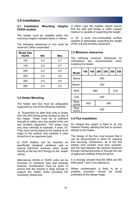
3.0 Installation<br />
3.1 Installation Mounting Heights<br />
OUHA models<br />
The Heater must be installed within the<br />
mounting heights indicated below in metres.<br />
The following clearances in mm must be<br />
observed *when suspended:<br />
Model Size<br />
OUHA Min Max<br />
100 2.0 2.7<br />
140 2.0 2.7<br />
200 2.4 3.0<br />
250 2.4 3.5<br />
300 2.5 3.5<br />
350 2.4 3.5<br />
3.2 Heater Mounting<br />
The heater and flue must be adequately<br />
supported by one of the following methods;<br />
a) Suspension by steel drop rods or straps<br />
from the M10 fixing points located on top of<br />
the heater. These must be of sufficient<br />
strength to safely carry the weight of the unit<br />
and ancillary equipment. The straps may<br />
only drop vertically to eyebolts, if used; I.E.<br />
They must not be joined to the eyebolt at an<br />
angle to the vertical, and eyebolts if used<br />
should be of an approved type.<br />
b) OUH heaters can be mounted on<br />
specifically designed cantilever wall or<br />
vertical stanchion brackets which locate<br />
directly to the four M10 fixings on the heater<br />
casing.<br />
Alternatively OUHA or OUHC units can be<br />
mounted on cantilever type wall brackets<br />
however consideration must be given to<br />
ensure that the bracket is large enough to<br />
support the heater whilst providing the<br />
necessary clearances.<br />
In either case the installer should ensure<br />
that the wall wall fixings or other support<br />
medium is capable of supporting the weight<br />
c) On a level non-combustible surface<br />
capable of adequately supporting the weight<br />
of the unit and ancillary equipment .<br />
3.3 Minimum clearances<br />
The following minimum clearances (in<br />
millimeters) are recommended when<br />
installing the heater.<br />
Model<br />
100 140 200 250 300 350<br />
Above 300<br />
Below* 300<br />
RHS 680 810<br />
LHS 250<br />
Rear<br />
OUHA<br />
Rear<br />
OUHC<br />
3.4 Flue Installation<br />
400 560<br />
200<br />
An integral flue spigot is fitted to all unit<br />
Heaters thereby allowing the flue to connect<br />
directly to the heater.<br />
The design of the flue must ensure that it<br />
can be disconnected to allow for cleaning<br />
and servicing, furthermore, all of the flue<br />
section joint sockets must face upwards,<br />
and the seal between the sections achieved<br />
through mechanical joints or through the use<br />
of approved caulking string and grout.<br />
It is strongly advised that BS 5854 and BS<br />
5440 parts 1 and 2 are referred to.<br />
Where condensation is likely to be a<br />
problem provision should be made<br />
preferably at the design stage.<br />
16


