BENSON OUH² OIL UNIT HEATER
Benson OUH2 Range OandM 3365190 Apr2012 issue7 ... - AmbiRad
Benson OUH2 Range OandM 3365190 Apr2012 issue7 ... - AmbiRad
- No tags were found...

You also want an ePaper? Increase the reach of your titles
YUMPU automatically turns print PDFs into web optimized ePapers that Google loves.
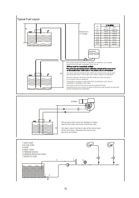
Typical Fuel Layout<br />
H<br />
Maximum<br />
4 metres<br />
H<br />
m<br />
0<br />
0.5<br />
1.0<br />
1.5<br />
2.0<br />
3.0<br />
3.5<br />
I.D.<br />
8mm<br />
35.0<br />
30.0<br />
25.0<br />
20.0<br />
15.0<br />
8.0<br />
6.0<br />
I.D.<br />
10mm<br />
100.0<br />
100.0<br />
100.0<br />
90.0<br />
70.0<br />
30.0<br />
20.0<br />
BURNER<br />
The pump suction should not exceed a maximum of 4 metres.<br />
Beyond this limit gas is released from t he oil.<br />
H<br />
The return line should terminate within the oil tank at the same level<br />
as the suction line; in this case a non return valve is not required.<br />
Should, however, the return line terminate over the fuel level,<br />
a non return valve is essential.<br />
This solution, however, is less safe than the previous one, due to<br />
possibility of leakage of the valve.<br />
Priming the pump: Start the burner and await priming.<br />
Should lock-out occur prior to arrival of the fuel, wait at least 20 seconds<br />
before repeating the operation.<br />
BURNER<br />
The pump suction must not exceed 4 metres;<br />
beyond this value the pump becomes noisy.<br />
H<br />
The return valve must termin ate at the same level<br />
as the foot valve, otherwise the pump may<br />
become air locked.<br />
1 GATE VALVE<br />
2 IN-LINE FILTER<br />
3 PUMP<br />
4 RELIEF VALVE<br />
5 PRESSURE GAUGE<br />
6 PRESSURE REDUCING VALVE<br />
7 RETURN TO TANK<br />
7<br />
4 5<br />
6 6<br />
3<br />
1 2<br />
10