

am..Brew
T'JTJ~~~ - Free and Open Source Software
T'JTJ~~~ - Free and Open Source Software
- No tags were found...

Create successful ePaper yourself
Turn your PDF publications into a flip-book with our unique Google optimized e-Paper software.
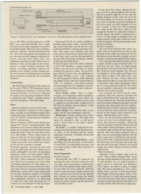
Continuedfrom page /6<br />
LpREPARED<br />
I+AROLIN E<br />
I'<br />
CENT ER CO ~ lACT -<br />
CE~TE R<br />
C~OR<br />
- 9/32 CE ~T E R<br />
CONOUC TOIl<br />
7LW<br />
•<br />
Figurt.' J. Cutawayof*wavt.' impedance con\'t.'r1er. showing allparts ofthe completed unit.<br />
rers on 432 MH z and nine quarters on 1296<br />
MHz. you could theoretically use a single<br />
line and set of 2-meter impedance conveners<br />
for all three bands . There are a few problems.<br />
however. with this " one line and matcher fits<br />
all." First. the more quarter wavelengths you<br />
use. the narrower the frequency respon se becomes.<br />
a nd th e more likel y that you r<br />
impedance matching sections will become attenuators<br />
if they are not right on the money .<br />
Second. a single feedline precludes fullduplex<br />
crossband operation required for<br />
satellite work. Finally. at those frequencies.<br />
the cost ofremote mounted antenna switching<br />
relays would far exceed the cost of separate<br />
feedlines!<br />
Construction<br />
The following co nstruction plan s appear [0<br />
be the easiest 500 to 750 impedance matching<br />
arrangemen t to du plicate. using the most<br />
common materials I've run across. Although<br />
this project was originally intended for Mode<br />
L uplink use only. Table I includes dimensions<br />
for all popular VHFfUHF bands.<br />
Parts<br />
Build two identical units for each cable.<br />
«Outer Conductor: Standa rd .lA-inch copper<br />
pipe. available at any plumhing supply house<br />
or hardware<br />
*<br />
store. Insu re that it actually measures<br />
~ (0 .875 ~) outside di<strong>am</strong>cter and has a<br />
0.032 ~ wall thickness.<br />
«Inner Conductor: Hobby brass tubing measuring<br />
9f32 - (0.281 ") outside di<strong>am</strong>eter. Miscellaneous<br />
sizes of brass tubing and assorted<br />
shapes are available in many hardware stores<br />
and model shops. These are typically stocked<br />
in t z-inch lengths. Where longer pieces are<br />
req uired . buy two 12-inch lengths for each<br />
co nverter and slip a 4-inch length of the next<br />
smaller size inside. then so lder them together.<br />
Be sure the asse mbly is straight.<br />
«Coa xial Connector: You ca n get away with<br />
using the UHF type (50-239) connector at 2<br />
meters. although it is not ideal. At any higher<br />
frequency. always use high quality Te fl on"<br />
and silver N connectors. normally designated<br />
UG-58fU. These co nnectors cost S3-5 each<br />
new. but if you are going to go to the trouble<br />
of buildi ng equipment for these bands. it is<br />
fal se economy to use cheap co nnectors . Also.<br />
stay away from the inexpensive bright nickel<br />
plated ones. as they will corrode. and usually<br />
do not have insulators capable of tolerating<br />
the so ldering heal required for asse mbling<br />
these impedance conveners. lr's depressing<br />
to watch the center melt and drop OUI of a<br />
connector as you attempt to solder the fla nge .<br />
18 73AmateurRadio . Juty, 1989<br />
Good used UG-58s are widely available at<br />
harnfests and surplus outlets . A good cleaning<br />
in the d ishwasher and the use o f a used<br />
(soft) Scotch-Brite" cleaning pad does wonde<br />
rs. Stay away from clea ning with steel<br />
wool . as you'llleave brass where silver used<br />
to be! Also. stee l wool has the bad habit of<br />
leaving little electrically-conductive strands<br />
in the least noticeable place!'>.<br />
«Center Contact: Since the ce nter cond uctor<br />
of the CATV hardlinc is copper-coated aluminum.<br />
you will need some fonn of finger<br />
connector for posi tive contact. The most elegant<br />
solution I have seen was published by<br />
Bill Olson W3HQT in his .. > 50" column<br />
for QEXmagazine in March. 1988. Bill used<br />
the double female center pin removed from a<br />
UHF " T" co nnector. cut in half 10 provide<br />
twoscrsoffingers for two impedance converters<br />
that just fit the hardline ce nte r conducto r.<br />
- Miscellaneous:<br />
Silver hobby solder. Th is is a highstrength<br />
. low-temperature solder available at<br />
most hardware and hobby stores. Silver solder<br />
resists corrosion in ou tdoor service. and<br />
is reputed to provide better conductivity to<br />
RF than it!'> ordinary lead-tin relative. It has<br />
separate solder and flux.<br />
Hose ch<strong>am</strong> ps. Use stainless steel. screw<br />
types. One for each impedance converter.<br />
Hand tools. Include a tubing cutter. hacksaw.<br />
small triangular file , and small steel<br />
square for alignment. Also. a small pencil<br />
torch is much easier to usc than a regular<br />
propane torch.<br />
So AI Ox"'. or similar compound for preventing<br />
corrosion between the aluminum outer<br />
jacket o f the hardline and the copper<br />
impedance convener . Available at electrical<br />
supply houses.<br />
A solderi ng a nd assembly fixture. made<br />
by drilling an Il fl6-inch hole . * inch deep in<br />
a wood board. Not absolutely necessary. but<br />
sure beat!'> trying to hold a hOI connecto r in<br />
you r fingers .<br />
Parts Preparation<br />
SOLDER<br />
.../ l".,<br />
eCcnrer Contacts:<br />
Disassembl e the UHF T connecto r by<br />
grasping the male connector ce nter pin with<br />
vise grips and unscrewing it counterclockwise.<br />
Drive the double female center conductor<br />
out of the end of the co nnector. Note that<br />
so me T co nnectors have a slight crimp on one<br />
end. so gently d rive the pin out the opposite<br />
end . Discard all pieces except the double<br />
female pin . Saw me dou ble female in half to<br />
make two center contacts. one for each end of<br />
you r hardline system.<br />
Fit the end of the contact opposite the fingers<br />
to the 9f3 2 center conductor tube. It may<br />
well be a perfect. tight fit . If not. tum the<br />
outside di<strong>am</strong>eter of the solid end to lit the<br />
9/32 tube tightly. It is best to use a lathe. but<br />
you ca n do a satisfacto ry job by chucking the<br />
pin in the chuck of a drill cl<strong>am</strong>ped in a vise<br />
and " turning" it with a fil e . When cl<strong>am</strong>ping<br />
the co ntact in the drill chuck . slide it in far<br />
enough for the jaws to co ntact the solid part,<br />
not the finge rs. Be ca refu l. Turning down a<br />
1/16 to I,t -inch length is adequate since the<br />
contact and the center tube conducto r will be<br />
soldered together. Set the prepared pins aside<br />
for later assembly.<br />
- Cemcr Conductor:<br />
One end of me 9f32-inch tube ce nter conductor<br />
must be necked down to the I,i inch<br />
di<strong>am</strong>eter of the solder pin on the UG-58. Do<br />
this before you cut the tube to length. so that if<br />
you goo f. you can cut the end off and try again.<br />
First. clea n the tube and insure that one end<br />
is square. Scribe a mark around the tube 3/32<br />
inch from the end. Then. cut eight equally<br />
spaced stors in the end of the tube to the 3/32<br />
line. with the small triangular file. file each<br />
slot slightly to create eight equal fingers that<br />
each taper to abou t 111 6 inch at the outer<br />
ends. Remove all burrs. Gently bend each<br />
finger inward a little at a time until you have a<br />
Ill-inch hole in the center. Be patient. Check<br />
the fit on the center pin of the UG-58. When<br />
you are satisfied. clean and tin the end lightly<br />
with the silver solder and n ux.<br />
Now assemble Ihe VG-58 and the ce nter<br />
conductor. Place the connector, threaded end<br />
do.....n. intothe hole in the " assembly fixture ."<br />
Tin the connector pin. Heat the necked-down<br />
end ofthe center conductor and slip it over the<br />
connector pin. then solder the two together .<br />
Whi le the joint is still hot. usc the steel square<br />
to insure that the ce nter conductor is perpendicu<br />
lar to the flange of the co nnector in all<br />
planes . Hold the piece until it cools.<br />
Next. lay the previously-prepared ce nter<br />
contact pin next to the soldered center co n<br />
ductor and connector assembly. Measuring<br />
from the insu lator-on the UG-58 outtothe end<br />
ofthe ce nter contact pin fingers. set the overall<br />
length to that required by the frequency of<br />
interest . Mark me ce nter conductor tube so<br />
that . whe n cut and pressed together with the<br />
center co ntact pin. it will be the right length .<br />
Cut the 9/32 lube. Clea n and deburr the end.<br />
Put some flux on it and press the center pin<br />
into the end of the tube. Rechec k the overall<br />
length. then solder. Remove all traces of nux<br />
with alcohol.<br />
«Outer Conductor:<br />
Standard a-Inch copper pipe with its<br />
O.03r wall is almost exactly 0 .065- larger<br />
than Ihe outside di<strong>am</strong>eter of the jacket on the<br />
~- inch hardline . So. we need to prepare a<br />
spacer sleeve to match the two di<strong>am</strong>eters.<br />
First. square one end o f a piece of copper<br />
pipe, then clean and deburr it. Now . with a<br />
tubing cu tter, cut off a l -inch long section.<br />
This length will be the space r sleeve. Now<br />
mark and saw a lA-inch wide section lengthwise<br />
from the side of this sleeve. Deburr Ihe<br />
cut. then compress the sleeve evenly until it will<br />
just start imo the end ofthe uncut copper pipe.


