

am..Brew
T'JTJ~~~ - Free and Open Source Software
T'JTJ~~~ - Free and Open Source Software
- No tags were found...

You also want an ePaper? Increase the reach of your titles
YUMPU automatically turns print PDFs into web optimized ePapers that Google loves.
•<br />
Special atte ntion has been given to the ground<br />
bus. The signal line grounds are run together<br />
to the upper right comer o f the board (as<br />
viewed from the component side-see Figure<br />
connect the outputs<br />
of an HF rig , 2 meter<br />
rig, and a phone<br />
patch . to the inputs<br />
of the mixer. You<br />
can then use an output<br />
to connect a tape<br />
recorder. You can<br />
adjust the inputs for<br />
proper level s. and<br />
record any ofthe input<br />
sources without<br />
constantly changing<br />
patch cords and adjusting<br />
levels. You<br />
can use another outeo<br />
" ••<br />
•, • ............. , ,".1<br />
•<br />
- ""~<br />
0<br />
. ~<br />
-ec<br />
••<br />
"<br />
Figure 4. Gain/frequency graph of low-pass<br />
filter. The cia-offfrequency is defined as 3 dB<br />
betow the nominal. The nominal gain here is<br />
12 dB. so rhe cut-off is 9 dB. which occurs<br />
around 6 kHz..<br />
1"' RIG<br />
I 12" A I,.<br />
11:m<br />
I. .....<br />
I<br />
. 1 1,.Pf<br />
I<br />
.~ " .<br />
~H ~~o 1""1<br />
I<br />
I<br />
,,,<br />
I ,<br />
I<br />
• I<br />
AuDIO<br />
" " ER<br />
I<br />
I<br />
::9,H.<br />
" OI.II< T[ O<br />
_ u£.<br />
FIgure 5. Suggested hook-up for the Four<br />
In/Fi ve Out mixer. You can monitorboth rigs<br />
f rom Ih~ s<strong>am</strong>e remote speaker.<br />
6). The power grounds from the op <strong>am</strong>ps<br />
are run together and terminate at the s<strong>am</strong>e<br />
corner. There are two connections at this<br />
point. One is for the power ground which is<br />
ru n with the +VDC wire. The second is for<br />
the connection [0 the enclosure. This should<br />
be the only connection to the chassis, thereby<br />
eliminating ground loops within the audio<br />
circuits.<br />
What Can You Do ",Uh It?<br />
Applications are not limited to repeaters. In<br />
the shack. multiple sources are often combined.<br />
You can replace the board-mounted<br />
trimpots with panel moun! pots, for easy adjustment.<br />
If the wire lengths exceed a couple<br />
of inches, be sure to use shielded wire. If you<br />
are driving the mixer from a speaker output.<br />
provide a suitable load for the source. Let me<br />
know ifyou come up with any unusual applications<br />
.<br />
One ex<strong>am</strong>ple is to<br />
P,"<br />
R1-R10<br />
Rll<br />
VR1-VR8<br />
Cl-C4<br />
CS,Cl1<br />
C6-Cl0<br />
U1-US<br />
D1<br />
D2<br />
Parts and Price List<br />
Description<br />
Total parts price listed above: $8.91<br />
put with a small audio <strong>am</strong>p for a remote<br />
speaker . This allows you 10 monitor both rigs<br />
on one speaker (see Figure 5).<br />
Construction of the Mixer<br />
The mixer, built from readily available<br />
pans, is designed for case of servicing. You<br />
can obtain pans mail order or from Radio<br />
Shack. Construction isn ' t critical; perf board<br />
is fine.<br />
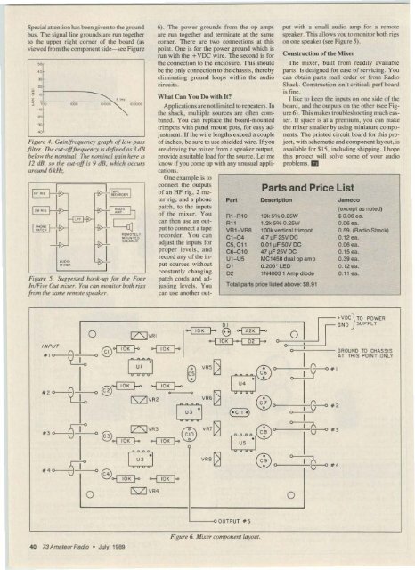
(like to keep the inputs on one side of the<br />
board , and the outputs on the other (see Figure<br />
6 ). This makes troubleshooting much easier.<br />
If space is at a premium, you can make<br />
the mixer smaller by using miniature components.<br />
The primed circuit board for this project,<br />
with sche matic and compo nent layout, is<br />
available for S15. including shipping. I hope<br />
this project will solve some of your audio<br />
problems. DI<br />
10k 5% 0.2SW<br />
1.2k 5% 0 .2SW<br />
lOOk vertical trimpot<br />
4 .7~F2SVDC<br />
0.01 ~ F SOV DC<br />
47~F 2 5V DC<br />
MC14S8 duai 01' <strong>am</strong>p<br />
0 .200~ LED<br />
1N4003 1 Amp diode<br />
J<strong>am</strong>eco<br />
(except as noted)<br />
$0.06 ea.<br />
O.06ea.<br />
0.59. (Radio ShaCk)<br />
0.12 ea.<br />
0.06 ea.<br />
0 .15ea.<br />
0.39 ea.<br />
0.12ea.<br />
0.11 ea.<br />
INPUT<br />
tt<br />
# 10<br />
tt<br />
0 IZSlVR '<br />
o@~ 10K b- 0-1 ro« f-<<br />
8 ~ V RS ~<br />
@o1 W ' f-- --I '0' f-<br />
# 20 o C2 ,<br />
0'<br />
..., 10 K f-< (;) 0-1 A2K f--<br />
., ro« H 02 f-o 0<br />
VR6~<br />
c2l0°<br />
U4<br />
0<br />
0 ,•<br />
a<br />
IS71 VR2 (00 ~---O_2<br />
'<br />
+ VOC} TO POWER<br />
NO SU PPLY<br />
I<br />
0 GROUND TO CHASSIS<br />
AT THIS POINT ONLY<br />
~<br />
0 #'<br />
# 3 0<br />
O@oj<br />
VSlVR' e<br />
10K ~ .,<br />
[3 (- Cll -) I<br />
0<br />
VR7 ~<br />
8<br />
0<br />
"'0<br />
'0' f-o •<br />
8'<br />
us<br />
' 0 0 ·3<br />
#4 0<br />
GJ 9+<br />
VRSk]<br />
C4 oj<br />
0<br />
0(8<br />
'0' l- -1 '0' f-<br />
IV IVR4<br />
@ =+G<br />
• 0 0#4<br />
0<br />
'-----" OUTPUT .5<br />
40 73 Amateur Radio • J uly. 1989<br />
Figure 6. Mixer component layout.


