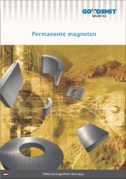
permanent magnets
Pdf brochure permanent magnets - Goudsmit Magnetics
Pdf brochure permanent magnets - Goudsmit Magnetics
- No tags were found...

Create successful ePaper yourself
Turn your PDF publications into a flip-book with our unique Google optimized e-Paper software.
<strong>permanent</strong> <strong>magnets</strong><br />
The Goudsmit Magnetic supplies premises in the<br />
Prunellalaan in Waalre.<br />
The showroom.<br />
The storehouse offers space for an exquisite buffer<br />
stock which is composed in consultation with our<br />
customers.<br />
Content<br />
Page 2:<br />
Goudsmit Magnetic Supplies BV<br />
Page 3:<br />
List of concepts A to D<br />
Page 4:<br />
List of concepts E to M<br />
Page 5:<br />
List of concepts N to Z & general<br />
properties of the different<br />
<strong>magnets</strong><br />
Page 6:<br />
Neoflux® <strong>magnets</strong><br />
Page 7:<br />
Neoflux® table<br />
Page 8:<br />
Samarium-Cobalt <strong>magnets</strong><br />
& table<br />
GOUDSMIT: DRIVEN BY MAGNETISM SINCE 1959!<br />
From the very beginning <strong>permanent</strong> <strong>magnets</strong> have played an important role in<br />
electrotechnics. Especially Alnico and Ferrite <strong>magnets</strong> have already been applied<br />
for years in loudspeakers, dynamos, motors and relays. Since the early seventies<br />
very powerful <strong>magnets</strong> have been produced on the basis of alloys from rare earth<br />
materials such as Samarium-Cobalt (SmCo) and Neodymium-Iron-Boron (NdFeB).<br />
Especially NdFeB <strong>magnets</strong>, at Goudsmit better known under the brand name<br />
Neoflux®, are applied in modern electronic applications. The number of <strong>magnets</strong><br />
used in airbags, starting motors, ABS systems, tachometers and in combination<br />
with sensors, has strongly increased in the automotive industry.<br />
Goudsmit Magnetic Supplies has been producing and supplying <strong>magnets</strong> and<br />
magnetic products already since 1959 and is NEN-EN-ISO 9001 certified. Goudsmit<br />
quality is guaranteed by a team of experienced and disciplined Qa engineers.<br />
They make use of the most advanced measuring systems such as the Permagraph,<br />
Helmholz coil, flux meters and CNC-controlled 3D measuring equipment. Apart<br />
from that Goudsmit also offers you good advice in the (re)design process of your<br />
product. This is done on the basis of consultancy and basically through 2d or<br />
3d computer simulations. An extensive stock program and an efficient logistic<br />
system enable them to provide you with the right <strong>magnets</strong> in a timely manner.<br />
Flexibility, trust and know-how form the basis of Goudsmit’s success.<br />
Page 9:<br />
Plastic-bonded <strong>magnets</strong> & table<br />
Page 10:<br />
Alnico <strong>magnets</strong> & table<br />
Page 11:<br />
Ferrite <strong>magnets</strong> & table<br />
ISO certified<br />
(no: 651218)
LIST OF CONCEPTS<br />
ANISOTROPIC—ISOTROPIC<br />
When some kind of magnetic material is pressed in a magnetic field this magnetic<br />
material is called preferentially-oriented and anisotropic. When this magnetic<br />
material is not pressed in a magnetic field, it is called isotropic. Later on isotropic<br />
magnetic material can be magnetised in all directions, anisotropic only in the<br />
preferential direction. The remanence (Br) of anisotropic magnetic material is (in<br />
preferential direction) about twice as high as the remanence of isotropic magnetic<br />
material (see figure 1).<br />
B<br />
See magnetic induction.<br />
(BH)max<br />
See maximum energy density.<br />
Br<br />
See remanence.<br />
Goudsmit checks the dimensions of<br />
your magnet by using the very newest<br />
CNC measuring equipment.<br />
COERCIVITY, NORMAL HcB<br />
The necessary field strength to make the magnetic induction in a magnetic<br />
material 0 (see demagnetisation curve). The “-”mark is usually left out in<br />
specifications. Units: A/m or Oe.<br />
COERCIVITY, INTRINSIC HcJ<br />
The necessary field strength to make the polarisation of a magnetic material 0<br />
(see demagnetisation curve). The “-”mark is usually left out in specifications.<br />
Units: A/m or Oe.<br />
CURIE TEMPERATURE<br />
Temperature above which magnetism completely disappears. Units °C en K<br />
among others.<br />
DEMAGNETISATION CURVE<br />
(2nd quadrant of the hysteresis curve)<br />
The demagnetisation curve of a kind of magnetic material is determined by<br />
putting the magnetic material in a closed system and by generating a magnetic<br />
field by means of coils first magnetising the material to saturation (+H) and<br />
then demagnetising (-H). During this process the polarisation of the magnetic<br />
material (J) is measured. The magnetic induction B in the magnet is calculated<br />
by means of the following formula:<br />
B=J+µ0 •H in which J = polarisation of material (share of material)<br />
µ0 •H = share of field<br />
<br />
<br />
<br />
<br />
<br />
<br />
<br />
<br />
Figure 1: demagnetisation curve of isotropic<br />
<br />
and anisotropic magnetic material.<br />
<br />
<br />
<br />
<br />
<br />
<br />
<br />
<br />
<br />
<br />
<br />
<br />
<br />
<br />
<br />
<br />
POSSIBILITIES OF MAGNETISATION<br />
Figure 2: demagnetisation curve.<br />
<br />
N S N<br />
N<br />
S<br />
h<br />
N<br />
Axially magnetised I&A<br />
• speakers<br />
• holding devices<br />
• magnetic switches<br />
• insert gas switches<br />
Magnetised through the<br />
height I&A<br />
• filtering systems<br />
• clamping devices<br />
• magnetic chokes<br />
• switches<br />
N<br />
N<br />
N<br />
S<br />
N<br />
N<br />
S<br />
N<br />
S<br />
N<br />
N<br />
S<br />
N<br />
N<br />
N<br />
S<br />
N<br />
N<br />
S<br />
N<br />
S<br />
N<br />
N<br />
S<br />
N<br />
S<br />
Radially magnetised I<br />
• holding <strong>magnets</strong><br />
• couplings (limited sizes<br />
available)<br />
Magnetised through<br />
diameter I<br />
• synchronous motors<br />
Laterally magnetised on<br />
surface picture shows<br />
6-pole configuration I<br />
• disc coupling<br />
• holding devices<br />
P<br />
S<br />
N<br />
S S<br />
N<br />
S<br />
N<br />
S<br />
N<br />
S<br />
N<br />
S<br />
<br />
<br />
<br />
<br />
<br />
<br />
<br />
N<br />
S<br />
N<br />
<br />
S<br />
N<br />
S<br />
N<br />
S<br />
<br />
N<br />
<br />
<br />
<br />
<br />
<br />
Multiple pole magnetised on<br />
inside surface picture shows<br />
4-pole configuration I<br />
• concentric ring<br />
• couplings<br />
• motors<br />
Laterally magnetised in<br />
lines on surface I (p=pole<br />
distance)<br />
• holding devices<br />
• magnetic chokes<br />
<br />
<br />
Radially magnetised I&A<br />
• motors<br />
<br />
<br />
<br />
N<br />
S S<br />
S N<br />
N N<br />
N S<br />
S<br />
Axially magnetised in<br />
segments with alternating<br />
poles I&A<br />
• synchronous motors<br />
• disc coupling<br />
S<br />
N<br />
N<br />
S<br />
N<br />
S<br />
N<br />
Multiple pole magnetised<br />
on outer surface picture<br />
shows 4-pole configuration I<br />
• dynamos<br />
• motors<br />
• concentric ring<br />
• couplings<br />
S<br />
N<br />
S<br />
N<br />
S<br />
N<br />
S<br />
N<br />
Diametrical magnetised I&A<br />
• motors<br />
I = isotroop<br />
A = anisotroop<br />
3
FLUX DENSITY<br />
See magnetic induction<br />
QUANTITIES AND UNITS<br />
A few widely used quantities with their units most used:<br />
Quantity Units Relation between units<br />
B<br />
magnetic induction<br />
B H<br />
Energy density<br />
H<br />
Magnetic field strength<br />
T (Tesla)<br />
G (Gauss)<br />
J/m 3 (Joule / meter 3 )<br />
GOe (Gauss·Oersted)<br />
A/m (Ampère/meter)<br />
Oe (Oersted)<br />
1 T = 10000 G<br />
1 kG = 0.1 T<br />
7.96 Kj/m 3 = 1 MGOe<br />
79.6 kA/m = 1 kOe<br />
Goudsmit checks the dimensions of your magnet by<br />
using the very newest CNC measuring equipment.<br />
HcB<br />
See coercivity, normal.<br />
HcJ<br />
See coercivity, intrinsic.<br />
IRREVERSIBLE LOSS, RECOVERABLE<br />
Permanent loss of magnetism due to too high temperatures for example. Only<br />
remagnetisation can restore the loss.<br />
IRREVERSIBLE LOSS, IRRECOVERABLE<br />
Permanent loss of magnetism due to too high temperature for example<br />
or oxidation. This loss is irrecoverable.<br />
ISOTROPIC<br />
See anisotropic.<br />
The Helmholz coil is used in combination with a flux<br />
meter to quickly and accurately measure the different<br />
formats and complex forms of magnetised SmCo,<br />
Neoflux® and ferrite <strong>magnets</strong>.<br />
J<br />
See magnetic polarisation.<br />
MAGNETIC INDUCTION, B<br />
Magnetic ordering in a material as a result of a magnetic field (H) and/or<br />
magnetic material (J) or: The number of magnetic field lines per unit area.<br />
Units: Including T and G.<br />
MAGNETIC POLARISATION, J<br />
Share of material to the magnetic induction. Units including T and G.<br />
MAGNETIC FIELD STRENGTH, H<br />
Magnetic power resulting in magnetic induction.<br />
The Permagraph checks whether the <strong>magnets</strong> meet<br />
the magnet specifications, possibly to a maximum<br />
temperature of 200 °C!<br />
MAXIMAL ENERGY DENSITY (BH)max<br />
Biggest possible product of B and H on the demagnetisation curve (see demagnetisation<br />
curve). In general the following holds: the bigger the (BH)max of magnetic<br />
material, the smaller might be the volume. The “-”mark is usually left out in<br />
specifications. Units: kJ/m3 and MGOe. Example: The volume of a GSN35 magnet<br />
can be ±10 x smaller than the volume of a GSF33H magnet and still have the same<br />
application.<br />
GENERAL PROPERTIES<br />
max. temperature of use<br />
Tw (°C)<br />
Reversible temperature<br />
coefficients; aBr (%/°C)<br />
Reversible temperature<br />
coefficients; aHcJ (%/°C)<br />
Ferrite<br />
Plastic bonded<br />
ferrite<br />
Neoflux®<br />
Plastic bonded<br />
Neoflux®<br />
SmCo<br />
225 120~150 80~230 160 250 450<br />
AINico<br />
-0.20 -0.2 -0.9~-0.12 -0.08~-0.12 -0.03~-0.05 -0.03<br />
+0.20<br />
/+0.50<br />
+0.3 -0.45~-0.85 -0.5 -0.3~-0.5 +0.02<br />
Curie temperature Tc (°C) 460 450 310~380 320 700~800 850<br />
Density (103 x kg/m3) 4.5~5.1 3.3~3.7 7.4~7.6 5~6.5 8~8.5 7.3<br />
Magnetisation and demagnetisation of <strong>magnets</strong> and<br />
magnet systems is performed in-house.<br />
Values only serve for comparing the kinds of material<br />
* Mechanical stress: Due to the brittleness of the materials it is not advisable to subject <strong>magnets</strong> to mechanical stress<br />
* Given magnetic properties for the materials are measured in accordance with the IE404-5 standard: the magnetic properties<br />
mentioned in the tables cannot be achieved for all magnet forms and dimensions
MAXIMAL APPLICATION TEMPERATURE<br />
Indication of the maximal temperature at which the magnetic material can be<br />
used with limited irreversible losses (see Working Point, Operating Line).<br />
PERMANENT MAGNET<br />
A magnet which completely or partially keeps its magnetism after being<br />
magnetised.<br />
<br />
<br />
<br />
<br />
<br />
<br />
PERMEABILITY<br />
The capacity of material to conduct magnetism. The permeability of vacuum<br />
(µ0) is 12.56•10-6 T/(A/m) or 1 G/Oe.<br />
<br />
<br />
<br />
<br />
REMANENCE Br<br />
Magnetic induction in magnetic material when the field strength is zero (H=0)<br />
and after saturation (see demagnetisation curve). Units: Including T and G.<br />
Figure 3: Demagnetisation curves and working<br />
point for any given Neoflux® magnet.<br />
REVERSIBLE LOSS<br />
Temporary loss of magnetism due to f.e. temperature change.<br />
TEMPERATURE COEFFICIENT (Br and HcJ)<br />
This indicates the reversible change (in percentage) of Br or HcJ in case of<br />
temperature change. The values depend on the kind of material, the quality and<br />
the temperature among other things.<br />
FREE POLES<br />
The field lines leaving the magnet go back to the magnet through the air<br />
(no ferromagnetic material).<br />
WORKING POINT / OPERATING LINE<br />
2 demagnetisation curves (only the normal curves) of random Neoflux® material<br />
are shown in figure 3. The working point (Bm, Hm) of a magnet is the point of<br />
intersection of the working line with the B-H curve. For <strong>magnets</strong> with free poles<br />
and without external magnetic field the angle of the working line with respect<br />
to the B axis depends on the relation between the length and diameter of the<br />
magnet; L 1 /D 1 > L 2 /D 2 Working line1 is closer to the B axis than the working line 2 .<br />
Goudsmit UK can advise you on a consultancy<br />
basis by means of computer simulations.<br />
We make use of the most advanced software<br />
to calculate your magnetic system.<br />
Permanent <strong>magnets</strong> are also available in a steel<br />
pot (if desired with a rubber cuff); these kinds of<br />
<strong>magnets</strong> have one attraction area which makes<br />
them a lot stronger.<br />
An advanced product such as a loudspeaker<br />
requests a dustproof magnet with the right<br />
magnetic and mechanical properties.<br />
Our delivery program also includes electro<br />
<strong>magnets</strong> .<br />
5
NEOFLUX® (Nd-Fe-B) MAGNETS:<br />
• Since 1986 Goudsmit has been selling NdFeB (Neodymium, Iron, Boron) <strong>magnets</strong> under the brand name<br />
Neoflux®.<br />
• Neoflux® is the strongest available <strong>permanent</strong> magnet with a maximal energy product of more than<br />
50 MGOe with an excellent coercivity.<br />
• A favourable price-quality ratio combined with the best possible magnetic properties.<br />
• Standard tolerances are ± 0.1 mm. If grinded ± 0, 05 mm. Tighter tolerances are available on request.<br />
• Processing is possible with diamond tools provided they are well cooled, as grinding residue can<br />
spontaneously ignite in combination with oxygen.<br />
• For the protection of corrosion Neoflux® <strong>magnets</strong> are provided with a coating which can consist of double<br />
Nickel, Nickel-Copper-Nickel, Zinc, Tin, Aluminium, Teflon or Epoxy, depending on the application.<br />
• Neoflux® <strong>magnets</strong> are always anisotropic which means that they can only be magnetised in preferential<br />
direction, axially and diametrically.<br />
• By using special coils Neoflux® can be magnetised in a multipoled way.<br />
• Neoflux® can be made in all kinds of shapes without additional tool costs; a clear drawing can avoid<br />
misunderstandings.<br />
• These <strong>magnets</strong> are not only used in motors, loudspeakers, separators, MRI scanners, windmills, electronics<br />
but also in cars, often in combination with sensors.<br />
• As Neoflux® <strong>magnets</strong> are mechanically spoken not as strong although very strong from a magnetic point<br />
of view, it is very important to handle them with great care.<br />
• Temperature of use is maximum 80°C to 200°C, depending on the specification, dimensions and system design<br />
• The minimum dimension for a block magnet is 1 x 1 x 1 mm, whereas the maximum dimension for this type<br />
is 160 x 150 x 50 mm.<br />
• The minimum dimension for a disc magnet is Ø 1.5 x 0.5 mm, whereas the maximum dimension for this<br />
type is Ø 150 x 50 mm.<br />
• The minimum dimension for a ring magnet is Ø 3 x Ø 1 x 1 mm, whereas the maximum dimension for this<br />
type is Ø 150 x Ø* x 50 mm (* inside diameter in consultation).
NEOFLUX® MAGNETS:<br />
Quality<br />
Remanence (Br)<br />
“Normal coercivity (HcB)”<br />
“Intrinsic<br />
coercivity<br />
(HcJ)”<br />
“Maximum energy density<br />
((B H)max )”<br />
T KG kA/m kOe kA/m kOe kJ/m 3 MGOe<br />
Min. Typ. Min. Typ. Min. Typ. Min. Typ. Min. Min. Min. Typ. Min. Typ.<br />
Max.<br />
temperature<br />
of use *<br />
GSN35 1.17 1.22 11.7 12.2 836 891 10.5 11.2 955 12 263 279 33 35 80<br />
GSN38 1.22 1.26 12.2 12.6 836 891 10.5 11.2 955 12 279 302 35 38 80<br />
GSN40 1.26 1.30 12.6 13.0 836 891 10.5 11.2 955 12 302 318 38 40 80<br />
GSN42 1.30 1.33 13.0 13.3 836 891 10.5 11.2 955 12 318 334 40 42 80<br />
GSN45 1.33 1.37 13.3 13.7 836 891 10.5 11.2 955 12 334 358 42 45 80<br />
GSN48 1.37 1.40 13.7 14.0 812 859 10.2 10.8 875 11 358 382 45 48 80<br />
GSN50 1.40 1.43 14.0 14.3 812 859 10.2 10.8 875 11 382 398 48 50 70<br />
GSN33M 1.14 1.17 11.4 11.7 812 859 10.2 10.8 1114 14 239 263 30 33 100<br />
GSN35M 1.17 1.22 11.7 12.2 836 891 10.5 11.2 1114 14 263 279 33 35 100<br />
GSN38M 1.22 1.26 12.2 12.6 859 915 10.8 11.5 1114 14 279 302 35 38 100<br />
GSN40M 1.26 1.30 12.6 13.0 859 915 10.8 11.5 1114 14 302 318 38 40 100<br />
GSN42M 1.30 1.33 13.0 13.3 859 915 10.8 11.5 1114 14 318 334 40 42 100<br />
GSN45M 1.33 1.37 13.3 13.7 859 915 10.8 11.5 1114 14 334 358 42 45 100<br />
GSN48M 1.37 1.41 13.7 14.1 859 915 10.8 11.5 1114 14 358 382 45 48 100<br />
GSN30H 1.08 1.14 10.8 11.4 780 812 9.8 10.2 1353 17 223 239 28 30 120<br />
GSN33H 1.14 1.17 11.4 11.7 812 875 10.2 11.0 1353 17 239 263 30 33 120<br />
GSN35H 1.17 1.22 11.7 12.2 836 891 10.5 11.2 1353 17 263 279 33 35 120<br />
GSN38H 1.22 1.26 12.2 12.6 859 915 10.8 11.5 1353 17 279 302 35 38 120<br />
GSN40H 1.26 1.30 12.6 13.0 859 915 10.8 11.5 1353 17 302 318 38 40 120<br />
GSN42H 1.30 1.33 13.0 13.3 859 915 10.8 11.5 1353 17 318 334 40 42 120<br />
GSN44H 1.33 1.37 13.3 13.7 859 915 10.8 11.5 1353 17 334 358 42 44 120<br />
GSN46H 1.35 1.37 13.5 13.7 859 915 10.8 11.5 1353 17 350 358 44 45 120<br />
GSN48H 1.37 1.40 13.7 14.0 859 915 10.8 11.5 1353 17 358 382 45 48 120<br />
GSN30SH 1.08 1.14 10.8 11.4 780 812 9.8 10.2 1592 20 223 239 28 30 150<br />
GSN33SH 1.14 1.17 11.4 11.7 812 875 10.2 11.0 1592 20 239 263 30 33 150<br />
GSN35SH 1.17 1.22 11.7 12.2 836 891 10.5 11.2 1592 20 263 279 33 35 150<br />
GSN38SH 1.22 1.26 12.2 12.6 859 915 10.8 11.5 1592 20 279 302 35 38 150<br />
GSN40SH 1.26 1.30 12.6 13.0 859 915 10.8 11.5 1592 20 302 318 38 40 150<br />
GSN42SH 1.30 1.33 13.0 13.3 859 915 10.8 11.5 1592 20 318 334 40 42 150<br />
GSN44SH 1.33 1.36 13.3 13.6 859 915 10.8 11.5 1592 20 334 358 42 44 150<br />
GSN28UH 1.04 1.08 10.4 10.8 780 812 9.8 10.2 1989 25 199 223 25 28 160<br />
GSN30UH 1.08 1.14 10.8 11.4 796 844 10.0 10.6 1989 25 223 239 28 30 160<br />
GSN33UH 1.14 1.17 11.4 11.7 812 875 10.2 11.0 1989 25 239 263 30 33 160<br />
GSN35UH 1.17 1.22 11.7 12.2 836 891 10.5 11.2 1989 25 263 279 33 35 160<br />
GSN38UH 1.22 1.26 12.2 12.6 836 891 10.5 11.2 1989 25 279 302 35 38 160<br />
GSN40UH 1.26 1.30 12.6 13.0 836 891 10.5 10.5 1989 25 302 318 38 40 160<br />
GSN28EH 1.04 1.08 10.4 10.8 780 812 9.8 10.2 2387 30 199 223 25 28 180<br />
GSN30EH 1.08 1.14 10.8 11.4 796 844 10.0 10.6 2387 30 223 239 28 30 180<br />
GSN33EH 1.14 1.17 11.4 11.7 812 875 10.2 11.0 2387 30 239 263 30 33 180<br />
GSN35EH 1.17 1.22 11.7 12.2 836 891 10.5 11.2 2387 30 263 279 33 35 180<br />
GSN38EH 1.22 1.26 1.22 12.6 836 891 10.5 11.2 2387 30 279 302 35 38 180<br />
At maximum temperature of use a magnet with free poles is considered without the presence of an external magnetic field.<br />
If the L/D ratio > 0.7 the irreversible loss is < 5%. We are always ready to give you advice!<br />
STABILISED NEOFLUX®:<br />
(°C)<br />
2 mg/cm 2 mass loss after 2 days of PCT<br />
Quality<br />
Remanence (Br)<br />
“Normal<br />
coercivity (HcB)”<br />
“Intrinsic<br />
coercivity (HcJ)”<br />
“Maximum energy density<br />
((BH)max)”<br />
T KG kA/m kOe kA/m kOe kJ/m 3 MGOe<br />
Min. Typ. Min. Typ. Min. Min. Min. Min. Min. Typ. Min. Typ.<br />
GSNS53N 1.44 1.50 14.4 15.0 >836 >10.5 >876 >11 398 430 50 54 80<br />
GSNS50M 1.40 1.46 14.0 14.6 >1043 >13.1 >1114 >14 374 406 47 51 100<br />
GSNS35EH 1.17 1.24 11.7 12.4 >868 >10.9 >2388 >30 263 295 33 37 200<br />
GSNS30AH 1.08 1.15 10.8 11.5 >804 >10.1 >2786 >35 223 255 28 32 230(**)<br />
GSNS33AH 1.14 1.21 11.4 12.1 >852 >10.7 >2786 >35 247 279 31 35 230(**)<br />
Exception: (**) the irreversible loss for these materials is < 3% with L/C ratio > 0.447)<br />
For the most actual specifications, dimensions and curves we invite you to have a look at our website: www.goudsmit<strong>magnets</strong>.com<br />
Max.<br />
temperature<br />
of<br />
use *<br />
(°C)<br />
7
SAMARIUM-COBALT MAGNETS:<br />
• Next to Neoflux® <strong>magnets</strong> Samarium-Cobalt (SmCo) <strong>magnets</strong> also belong to the group of rare earth <strong>magnets</strong>.<br />
• SmCo <strong>magnets</strong> have very good magnetic properties with a maximum energy product of 18 to 30 MGOe,<br />
a low temperature coefficient and high stability.<br />
• The maximum temperature of use is 250°C depending on the specification, dimensions and system design.<br />
• SmCo <strong>magnets</strong> are well resistant against oxidation and - as long as they are used under normal conditions<br />
- do not require a coating.<br />
• SmCo <strong>magnets</strong> are often the best choice for applications in which durability is very important such as for<br />
high-quality electronic products, medical devices and in the automobile industry.<br />
• De cost price of SmCo <strong>magnets</strong>, in comparison with Neoflux®, is a lot higher due to the high, unstable<br />
Cobalt prices.<br />
• SmCo is very fragile.<br />
• The minimum dimension for a block magnet is 2 x 2 x 1 mm, whereas the maximum dimension for this<br />
type is 120 x 52 x 52 mm.<br />
• The minimum dimension for a disc magnet is Ø 2 x 1 mm, whereas the maximum dimension for this type<br />
is Ø 90 x 50 mm.<br />
• The minimum dimension for a ring magnet is Ø 3 x Ø 1.5 x 1 mm, whereas the maximum dimension for this<br />
type is Ø 90 x Ø* x 50 mm (* inside diameter in consultation).<br />
“Intrinsic<br />
coercivity<br />
(HcJ)”<br />
“Maximum energy density<br />
((BH)max)”<br />
Max. temperature<br />
of use *<br />
Remanence (Br)<br />
“Normal coercivity (HcB)”<br />
Quality<br />
T KG kA/m kOe kA/m kOe kJ/m 3 MGOe<br />
Min. Typ. Min. Typ. Min. Typ. Min. Typ. Min. Typ. Min. Typ. Min. Typ.<br />
(°C)<br />
GSS20 0.92 0.94 9.2 9.4 653 685 8.2 8.6 >1194 >15 150 158 18.8 19.8 250<br />
GSS23 0.95 0.98 9.5 9.8 637 684 8.0 8.6 >1433 >18 175 182 22 22.9 250<br />
GSS27 1.05 1.07 10.5 10.7 756 776 9.5 9.7 >1433 >15 205 212 25.8 26.6 300<br />
GSS29 1.08 1.09 10.8 10.9 780 796 9.8 10.0 >955 >12 220 230 27.6 28.9 300<br />
For the most actual specifications, dimensions and curves we invite you to have a look at our website: www.goudsmit<strong>magnets</strong>.com
PLASTIC-BONDED FERRITE MAGNETS:<br />
• Plastic-bonded <strong>magnets</strong> can be manufactured by pressing or injection-moulding using basic<br />
materials consisting of ferrite, Neoflux® or Samarium-Cobalt. It is mixed with a thermoplastic<br />
material such as polyamide.<br />
• The advantage of this material is that it can be pressed or injection-moulded in very capricious shapes,<br />
with strict tolerances of ± 0.05 mm without finishing.<br />
• Although plastic-bonded Neoflux® <strong>magnets</strong> have a greater resistance to corrosion that sintered Neoflux®,<br />
it is advisable to apply a coating to them.<br />
• Thanks to the isotropy, this material can be magnetised in various directions (see page 3).<br />
Quality<br />
Remanence (Br) “Normal coercivity (HcB)” “Intrinsic coercivity (HcJ)”<br />
“Maximum energy density<br />
((BH)max)”<br />
T KG kA/m kOe kA/m kOe kJ/m 3 MGOe<br />
Min. Typ. Min. Typ. Min. Typ. Min. Typ. Min. Typ. Min. Typ. Min. Typ. Min. Typ.<br />
GSFI-1 0.11 0.13 1.1 1.3 70 85 0.88 1.07 190 230 2.39 2.89 1.5 3.0 0.19 0.38 120<br />
GSFI-2 0.13 0.18 1.3 1.8 85 125 1.07 1.57 190 230 2.39 2.89 3.0 3.6 0.38 0.45 120<br />
GSFI-3 0.21 0.24 2.1 2.4 120 170 1.50 2.13 160 230 2.01 2.89 7.0 12.0 0.87 1.50 120<br />
GSFI-4 0.25 0.26 2.5 2.6 165 195 2.07 2.45 210 320 2.63 4.02 11.0 13.0 1.38 1.63 120<br />
GSFI-5 0.27 0.28 2.7 2.8 170 200 2.13 2.51 210 320 2.63 4.02 14.03 15.1 1.80 1.90 120<br />
GSFI-6 0.28 0.29 2.8 2.9 180 190 2.26 2.38 210 230 2.63 2.89 15.9 16.5 2.0 2.07 120<br />
Max. temperature<br />
of use *<br />
(°C)<br />
PLASTIC-BONDED NEOFLUX® MAGNETS:<br />
Quality<br />
Remanence (Br) “Normal coercivity (HcB)” “Intrinsic coercivity (HcJ)”<br />
“Maximum energy density<br />
((BH)max)”<br />
T KG kA/m kOe kA/m kOe kJ/m 3 MGOe<br />
Min. Typ. Min. Typ. Min. Typ. Min. Typ. Min. Typ. Min. Typ. Min. Typ. Min. Typ.<br />
GSNB-4 0.35 0.4 3.5 4.0 240 260 3.0 3.2 640 720 8.0 9.0 24 28 3.0 3.5 150<br />
GSNB-6 0.5 0.55 5.0 5.5 320 340 4.0 4.3 640 720 8.0 9.0 40 48 5.0 6.0 150<br />
GSNB-8 0.6 0.63 6.0 6.3 360 400 4.5 5.0 640 760 8.0 9.5 64 68 8.0 8.5 140<br />
GSNB-8H 0.56 0.61 5.6 6.1 400 432 5.0 5.4 960 1160 12.0 14.5 60 66 7.5 8.3 120<br />
GSNB-10 0.68 0.70 6.8 7.0 400 420 5.0 5.2 640 720 8.0 9.0 72 76 9.0 9.5 120<br />
GSNB-12 0.7 0.75 7.0 7.5 416 448 5.2 5.6 640 720 8.0 9.0 80 88 10.0 11.0 130<br />
GSNB-12D 0.7 0.75 7.0 7.5 448 464 5.6 5.8 720 840 9.0 10.5 80 88 10.0 11.0 140<br />
Max. temperature<br />
of use *<br />
(°C)<br />
9<br />
For the most actual specifications, dimensions and curves we invite you to have a look at our website: www.goudsmit<strong>magnets</strong>.com
ALNICO MAGNETS:<br />
• Alnico <strong>magnets</strong> are made of Aluminium, Nickel, Cobalt and Iron and have already been applied since 1930.<br />
Sometimes a few other elements such as copper, titanium and niobium are added.<br />
• Alnico <strong>magnets</strong> have a maximum energy product of 1 to ± 9 MGOe and do not require coating when used<br />
under normal conditions.<br />
• The maximum temperature of use is 450°C depending on the specification, dimensions and system design.<br />
• Most of the Alnico <strong>magnets</strong> are caste and in this process the alloy, which is liquid, is poured into sand<br />
moulds at very high temperature.<br />
• Some of these <strong>magnets</strong> are pressed and sintered.<br />
• Casting Alnico can happen in complex forms, such as horseshoes for example.<br />
• Sintered Alnico has slightly lower magnetic properties however they have better mechanical properties<br />
than caste alnico, with very small casting amounts during the casting process.<br />
• Standard tolerance for grinded alnico is ±0.1 mm, depending on the size and shape.<br />
• It is important (watch out!) that the length/diameter ratio is kept, this will prevent demagnetisation.<br />
• The minimum dimension for a block magnet is 2 x 2 x 2 mm, whereas the maximum dimension for this<br />
type is 100 x 100 x 100 mm.<br />
• The minimum dimension for a disc magnet is Ø 1 x 2 mm, whereas the maximum dimension for this type<br />
is Ø 100 x 100 mm.<br />
• The minimum dimension for a ring magnet is Ø 5 x Ø 3.5 x 1 mm, whereas the maximum dimension for this<br />
type is Ø 200 x Ø* x 50 mm (* inside diameter in consultation).<br />
Quality<br />
Remanence (Br)<br />
“Normal coercivity<br />
(HcB)”<br />
“Intrinsic coercivity<br />
(HcJ)”<br />
“Maximum energy<br />
density ((BH)max)”<br />
T KG kA/m kOe kA/m kOe kJ/m 3 MGOe<br />
Min. Min. Min. Min. Min. Min. Min. Min.<br />
GSA5A 1.20 12.0 48 0.600 49 0.62 36 4.50 450<br />
GSA5B 1.25 12.5 55 0.69 57 0.72 47 5.90 450<br />
GSA6 1.30 13.0 56 0.70 58 0.73 60 7.50 450<br />
GSA8 0.80 8.0 110 1.380 111 1.40 37 4.70 450<br />
GSAS5A 1.10 11.0 48 0.60 51 0.64 34 4.25 450<br />
GSAS5B 1.00 10.0 56 0.70 57 0.71 28 3.50 450<br />
Max. temperature<br />
of use *<br />
For the most actual specifications, dimensions and curves we invite you to have a look at our website: www.goudsmit<strong>magnets</strong>.com<br />
(°C)
FERRITE MAGNETS (ceramic <strong>magnets</strong>):<br />
• Ferrite or ceramic <strong>magnets</strong> are still the most widely used <strong>magnets</strong> with a maximum energy product of<br />
1 to ± 4.3 MGOe.<br />
• Due to the environmental requirements which are becoming more stringent barium ferrite has been<br />
replaced by strontium ferrite during the last years.<br />
• Ferrite is the cheapest magnetic material and has a high corrosion resistance making coating unnecessary.<br />
• This magnetic material is hard and fragile and must be processed with diamond, preferably when it is not<br />
in a magnetic state.<br />
• Because it might shrink during the sinter process a tolerance of ± 2 % should be taken into account when<br />
determining the dimensions. If grinded ± 0.1 mm.<br />
• Tighter tolerance is available on request.<br />
• Ferrite <strong>magnets</strong> can be supplied both isotropically as anisotropically and are used in the most divergent<br />
products such as loudspeakers, magnetrons, measuring devices, toys, engines, reed contacts etc.<br />
• The maximum temperature of use is 225°C depending on the specification, dimensions and system design.<br />
• For specifications: See the table below. For magnetisation possibilities: see page 3.<br />
• The minimum dimension for block <strong>magnets</strong> is 2 x 2 x 2 mm, whereas the maximum dimension for this<br />
type is 270 x 90 x 25.4 mm.<br />
• The minimum dimension for disc <strong>magnets</strong> is Ø 2 x 1 mm, whereas the maximum dimension for this type is<br />
Ø 156 x 25.<br />
• The minimum dimension for ring <strong>magnets</strong> is 8 x 2.5 x 3 mm, whereas the maximum dimension for this<br />
type is Ø 256 x Ø* x 25 mm (* inside diameter in consultation).<br />
Quality<br />
Remanence ( (Br) “ Normal coercivity (HcB)” “Intrinsic coercivity (HcJ)”<br />
“Maximum energy density<br />
((BH)max)”<br />
T KG kA/m kOe kA/m kOe kJ/m 3 MGOe<br />
Min. Typ. Min. Typ. Min. Typ. Min. Typ. Min. Typ. Min. Typ. Min. Typ. Min. Typ.<br />
GSFD-10 0.21 0.23 2.1 2.3 127 159 1.60 2.00 211 235 2.65 2.95 5.6 8.8 0.7 1.1 225<br />
GFSD-25 0.38 0.40 3.8 4.0 143 175 1.8 2.2 147 179 1.85 2.25 23.9 27.1 3.0 3.4 225<br />
GFSD-30 0.39 0.41 3.9 4.1 175 207 2.20 2.60 179 211 2.25 2.65 25.5 28.7 3.2 3.6 225<br />
GFSD-33H 0.39 0.41 3.9 4.1 239 271 3.0 3.4 243 275 3.05 3.45 27.1 30.3 3.4 3.8 225<br />
Max. temperature<br />
of use *<br />
GFSD-34H 0.370 0.390 3.70 3.90 263 291 3.30 3.65 307 330 3.85 4.15 28.7 30.3 3.6 3.8 225<br />
GFSD-42 0.415 0.435 4.15 4.35 215 239 2.70 3.00 219 243 2.75 3.05 31.2 34.4 3.9 4.3 225<br />
11<br />
For the most actual specifications, dimensions and curves we invite you to have a look at our website: www.goudsmit<strong>magnets</strong>.com<br />
(°C)
www.goudsmit<strong>magnets</strong>.com<br />
Goudsmit Magnetic Supplies B.V.<br />
Prunellalaan 14<br />
P.O. Box 7<br />
5580 AA Waalre<br />
The Netherlands<br />
Tel.: +31-(0)40-2219015<br />
Fax: +31-(0)40-2220256<br />
www.goudsmit<strong>magnets</strong>.com<br />
supplies@goudsmit-magnetics.nl<br />
Folder number: 07/73