www.etisalat.ae Design guide
www.etisalat.ae Design guide
www.etisalat.ae Design guide

You also want an ePaper? Increase the reach of your titles
YUMPU automatically turns print PDFs into web optimized ePapers that Google loves.
<strong>Design</strong> <strong>guide</strong><br />
Index<br />
<strong>www</strong>.<strong>etisalat</strong>.<strong>ae</strong><br />
Subject Page<br />
Introduction 2<br />
General telecom requirements 3<br />
Civil requirements applicable for all types of buildings 3<br />
Entry box 3<br />
Entry pipes 3<br />
Main telecom room 4<br />
Floor telecom room 4<br />
Roof-top telecom room 4<br />
Risers from main telecom room to individual floors 5<br />
Floor distribution box 5<br />
Flat distribution-from indoor equipment cabinet 6<br />
Villa floor distribution-from indoor equipment cabinet 6<br />
Installation of in-building fibre drop cables 6<br />
High-rise buildings 6<br />
Single villas 7<br />
Etisalat telecom requirements 7<br />
Etisalat telecom requirements-Table 1 7<br />
Etisalat telecom requirements-Table 2 8<br />
Structured Cabling System (SCS) 9<br />
Cabling & termination 9<br />
Telecommunication cabling 9<br />
Telecommunication socket 9<br />
Accessories 10<br />
Horizontal subsystem (UTP Cables) 10<br />
Cable capacities in trays conduits 11<br />
Indoor equipment cabinet 19” 11<br />
A) Free standing types 11<br />
B) Wall-mounted type cabinets 12<br />
Under-floor systems 12<br />
Main elements of under-floor raceway systems 12<br />
Protection from electromagnetic interference 13<br />
Electrical requirements 15<br />
Important notes 15<br />
List of annexures 16
1<br />
<strong>Design</strong> <strong>guide</strong> <strong>www</strong>.<strong>etisalat</strong>.<strong>ae</strong><br />
Introduction<br />
Introduction<br />
Telecommunication is now an integral part of social,<br />
economic and political issues of the world. Networks of<br />
the future will be digital and intelligent and will offer high<br />
transmission capacity and flexible bandwidth; in addition,<br />
they will be easily accessed and connected while its<br />
services will be personal and tailored to individual needs.<br />
These will allow us to interact in ways previously not<br />
possible - available at any time and any place. In addition<br />
to providing entertainment and business services, networks<br />
of the future will provide education, health and other<br />
public services.<br />
Major advances in communications technology have<br />
substantially widened the range of services carried by<br />
the network. Satellites, microwave radio, optical cable<br />
links, digital switching and transmission, offer a potential<br />
for the improvement of quality and for the extension of<br />
access to the most remote areas. The pace of technological<br />
change is increasing while the magnitude of demands the<br />
future will make on our creativity and capacity to adapt<br />
is great. Customers will demand more than just stateof-the-art<br />
technology; they will want convenience and<br />
increased control in their lives that affordable information<br />
access can provide. While businesses will look for total<br />
telecommunications solutions that will not only enable<br />
them to remain productive and compete globally but will<br />
also give them a competitive edge.<br />
Etisalat can be well-placed to meet these challenges ahead<br />
and meet the varied needs of our local and international<br />
customers and pave the way for the region’s new dynamism<br />
in the telecommunications industry well into the 21st<br />
century.<br />
As technology and mode of transport are changing fast, a<br />
broad approach to suit all future type of services will have<br />
to be borne in mind, while designing the infrastructures for<br />
buildings. A properly designed building with clear Access<br />
Path supports the triple play services, viz telephony, data<br />
and video services. Also, supports future advanced services,<br />
warranting higher speeds and higher bandwidth, planned to<br />
be available in near future, for faster provision of services.<br />
The present booklet is to provide <strong>guide</strong>lines for consultants,<br />
contractors and the details on the in-building facilities<br />
required to be considered at the design stage.<br />
The details provided are a general insight and the minimum<br />
requirements of Etisalat for the new buildings, primarily to<br />
develop and deploy FTTX (Fibre to Home), based on GPON<br />
technology.<br />
2
<strong>Design</strong> <strong>guide</strong> <strong>www</strong>.<strong>etisalat</strong>.<strong>ae</strong><br />
General telecom requirements<br />
To provide telecom services, the internal concealed pipe<br />
and other associated requirements vary for the different<br />
building types. The various types of buildings are grouped<br />
as commercial buildings, residential towers, ware houses,<br />
medium high-rise buildings, shopping complexes, retail<br />
houses, row houses, independent villas, campus villas,<br />
labour camps, mosques, petrol pumps, etc.<br />
The building owners, builders, property developers,<br />
consultants and contractors are advised to provide the<br />
various in–building requirements, as applicable, to ensure<br />
timely provision of services.<br />
Civil requirements applicable for all types<br />
of buildings<br />
Entry box<br />
Entry box is an underground joint box built, exclusively to<br />
allow installation of Etisalat underground cable network to<br />
the customer’s premises.<br />
• The entry box is a reinforced concrete structure, with a<br />
heavy duty Ductile Iron Frame and Cover of rating grade ‘A’<br />
and size is 60x60x80 cm. The cover shall have marking as<br />
“Telephones”<br />
• The location of the entry box, depends on the location of<br />
existing/proposed Etisalat external line plant<br />
• The entry box should be constructed at a maximum<br />
distance of 1 meter from plot line. If it is not practical to<br />
install within the plot, then install it outside the plot. Make<br />
sure it touches the boundary wall<br />
• Due to the variables involved, it is essential to consult<br />
Etisalat at the design stage, to decide the location<br />
of the entry box and entry pipe. The consultants/<br />
contractors must not deviate from the stipulated location<br />
• An earth rod must be provided at the entry box. The<br />
required earth resistance should not exceed more than 5<br />
ohms<br />
• For entry box size details please refer to Table No. 1<br />
Entry pipes (Lead-in ducts)<br />
The entry pipes are uPVC ducts. These ducts are to be<br />
extended from the entry box towards premises and towards<br />
Etisalat line plant location.<br />
• Entry pipes should be laid at a depth of 60 cm from the<br />
proposed finished paving level. The entry pipe must be<br />
protected with concrete to prevent damages<br />
• Entry pipe should be extended to the entry box and<br />
beyond to the nearest existing Etisalat plant location, or 1<br />
meter from plot limit or as advised by Etisalat<br />
• The entry pipe should be of uPVC material and of black<br />
color<br />
• The open ends of the entry pipe must be properly sealed,<br />
to prevent entry of sub-soil materials and ingress of water<br />
• Location of entry pipes must be clearly marked, above<br />
ground for easy location<br />
• Building contractors shall be responsible to locate the<br />
installed entry pipes on site, if requested by Etisalat<br />
• No right-angled sharp bends should be installed through<br />
out the duct length, except one wide-angle, long radius<br />
bend (factory made) at the terminating end of the duct,<br />
inside the main telecom room. Alternatively, at the location<br />
of the wide angle bend, a cable pull box of minimum size<br />
600(L) x 700(W) x 800(D) mm must be provided<br />
• Entry pipes must be assigned, exclusively for Etisalat<br />
telecommunication services<br />
• Entry pipes must be provided with a draw rope made of<br />
nylon of minimum 6 mm diameter<br />
• For the number and size of entry pipes, for the various<br />
types of buildings, please refer to Table 1<br />
Main telecom room<br />
Main telecom room should be a dedicated room. This is to<br />
be provided either on the ground floor or basement or in<br />
the first floor or mezzanine floor of the building for the<br />
purpose of terminating telecommunication cables and to<br />
house the present & future telecom equipment. The room<br />
must be exclusively for Etisalat use<br />
• The room must be easily accessible to Etisalat Personnel<br />
24 hr./day, (all days including weekends). The room<br />
must be clean, dry and free from dust and secured from<br />
unauthorized entry<br />
• Adequate lighting and minimum of four 20 amp and<br />
240 volt A.C. Mains outlet from a dedicated circuit breaker<br />
should be provided<br />
• The room must be air-conditioned and a “raised floor” of<br />
minimum 30 cm should be provided if required, depending<br />
on the telecom room usage<br />
• The room must be provided with a good earth rod of not<br />
more than 5 ohms<br />
• The door opening for the room should swing outwards<br />
• The floor, roof and surrounding wall of the telecom room,<br />
should be free of any concealed water/drainage pipes and<br />
air-conditioning ducts passing through<br />
• The room must be provided with an emergency light, a<br />
smoke detector and a fire alarm<br />
• If the telecom room is proposed in the basement, an<br />
automatic sump draining system must be provided to<br />
handle water seepages<br />
• The duct entry to building must be sealed air and water<br />
tight<br />
• For the main telecom room size, please refer Table No. 1<br />
Floor telecom closet<br />
Floor telecom closet is a dedicated closet and required on<br />
each floor for the purpose of routing and/or terminating<br />
telecommunication cables. The room should be exclusively<br />
for Etisalat use<br />
• The closet must readily be accessible to Etisalat personnel<br />
and equipment 24 hr./day, all the days, round the clock and<br />
the closet, clean dry, and free from dust and secured from<br />
unauthorized entry<br />
• The door opening for the closet should swing outwards,<br />
when opened<br />
• For the floor telecom closet size, please refer Table No. 1<br />
Roof-top telecom room<br />
Roof-top telecom room, is a dedicated room to be provided<br />
on the roof-top of the proposed multi-storey buildings,<br />
exclusively for Etisalat use and secured from unauthorized<br />
entry. The minimum roof-top telecom room size should be<br />
3(L) x 3(W) x 3(H) meter<br />
• The floor loading of this area must be maximum possible,<br />
to support future installation of telecommunications<br />
equipment<br />
• An opening of size 60x40 cm to be provided on the wall<br />
of the room, facing the terrace, 50 cm below the room<br />
ceiling<br />
3 4
<strong>Design</strong> <strong>guide</strong> <strong>www</strong>.<strong>etisalat</strong>.<strong>ae</strong><br />
• The location of the room should be within the vertical<br />
structure of the building, with due considerations for load<br />
safety provisions and to extend related facilities required<br />
such as air-conditioning, 3-phase power (Distribution<br />
Board) DB, earthing less than 5 ohms, adequate lighting,<br />
one 13 amp 240 v AC power socket and one telephone<br />
socket<br />
• The room must be provided with an emergency light, a<br />
smoke detector and a fire alarm<br />
• The room must readily be accessible to Etisalat<br />
personnel and equipment 24 hr every day, all the days,<br />
round the clock and the room must be clean, dry and free<br />
from dust<br />
Risers from main telecom room<br />
to individual floors<br />
The risers are required in multiple-storey buildings for<br />
the installation of telecom fibre optic cables from main<br />
telecom room to other floors, as detailed below:-<br />
• Galvanized slotted iron cable trays (minimum 200x50<br />
mm HDRF (Heavy Duty, Return Flange) should be provided<br />
from the main telephone room, to each telephone closet<br />
and extended up to the roof telephone room<br />
• The risers to each floor must be symmetrical and<br />
vertically in line with the main telecom room.<br />
However, where the main telecom room, floor telephone<br />
closet and roof telecom rooms are to be located one<br />
below the other in vertical line, a continuous cable trays/<br />
conduits must be provided with pull boxes/access panels at<br />
every turning point and at interval of 15 meters each, up to<br />
the main telecom room. Right angle or sharp bends are to<br />
be avoided<br />
• If a building consists of more than one tower, all the<br />
above specified requirements are required in each tower<br />
The towers must be inter-connected at the main telecom<br />
room, by separate cable trays of minimum 2 nos. and size<br />
200x50 mm or through floor raceways passing through<br />
a common area between the two buildings. The size of<br />
the floor raceways is to be decided at the design stage by<br />
Etisalat. The same requirements also apply to mezzanine<br />
and penthouse floors. The telecom cable trays should have<br />
adequate separation from electrical cable trays. Electrical<br />
cable trays should not cross the telecom cable trays.<br />
Floor distribution box<br />
Floor distribution boxes are metallic boxes, concealed,<br />
located on the wall, where the internal conduit from every<br />
flat is terminated. These empty boxes, should be located<br />
close to the risers and can be more than one, depending<br />
upon the number of flats and conduits proposed to be<br />
terminated. These distribution boxes facilitate to route the<br />
fibre optic cables to the premises direct and the number of<br />
cables corresponds to the number of flat/premises.<br />
• The distribution boxes should be of size not less than<br />
30(L) X 30(H) X 15(D) flush mounted on wall and should<br />
be fixed inside the telecom closet of each floor. A suitable<br />
hinged cover must be provided<br />
• It should be installed at a height of 120 cm above the<br />
finished floor level<br />
• The conduits leading from the floor distribution box<br />
towards flat, should not be less than 25 mm diameter<br />
• Adequate safe working space is to be provided around<br />
each location<br />
• The distribution boxes on a floor, should not be linked to<br />
or serve any other floor of the building<br />
• The distribution boxes location should never be near any<br />
electrical junction box or bus bars. Adequate safe working<br />
space should be provided in front of each box<br />
• A single conduit of at least 25 mm (1 inch) internal dia.,<br />
black and of uPVC material should be provided from each<br />
floor distribution box to the indoor equipment cabinet of<br />
each office, residence, flat and other independent areas in<br />
the same floor<br />
• Etisalat should be consulted to enhance the requirements,<br />
if the building is designed for commercial use<br />
Flat distribution<br />
– from indoor equipment cabinet<br />
• A secured indoor equipment cabinet should be of<br />
minimum size 12 U and width 600 mm and depth 515 mm<br />
to house the Optical Network Unit (ONU), power sockets<br />
and patch panel/IDC modules and battery. The cabinet<br />
should be flush mounted on wall. The cabinet should be<br />
dedicated to each office/residential flat and to be sited in a<br />
secured place. The location shall be suitable for technician’s<br />
access, when required<br />
• The location of the indoor equipment cabinet should be<br />
at a common point, where all the internal conduits meet<br />
and the Structured Cabling System (SCS) on a star topology<br />
can be installed. However, the farthest socket must not<br />
exceed 90 m from the cabinet<br />
• Two power sockets are required, inside the indoor<br />
equipment cabinet, for powering the optical network unit<br />
and battery rectifier<br />
• The cabinet distribution box location should not be<br />
adjacent to any electrical distribution or bus bars<br />
• The cabinet distribution box should be installed at a<br />
height of 120 cm above the finished floor level<br />
• All internal conduits should be of a diameter not less<br />
than 25 mm (1 inch) to extend the structured cables from<br />
ONU to SCS socket locations at each room<br />
Villa distribution<br />
- from indoor equipment cabinet<br />
• A secured indoor equipment cabinet, should be of<br />
minimum size 12 U and width 600 mm and depth 515 mm<br />
to house the Optical Network Unit (ONU), power sockets<br />
and patch panel/IDC modules and battery. The cabinet<br />
should be flush mounted on wall. The cabinet should be<br />
dedicated on each villa and to be sited in a secured place.<br />
The location must be suitable for technician’s access, when<br />
required<br />
• A secured distribution box of size 30 (L)x30 (H)x15 (W) cm<br />
flush mounted on wall is required in every floor of the villa,<br />
for distributing SCS, from the indoor cabinet<br />
• The floor distribution box should be kept at a convenient<br />
and easily accessible location where the floor distribution<br />
conduits are terminated. It should be installed at a height<br />
between 40 cm and 120 cm above the finished floor level<br />
• The distribution boxes on different floors of a villa should<br />
be connected through a PVC conduit, of a 50 mm diameter<br />
• The distribution box should have one 50 mm (2 inch)<br />
conduit to the rooftop of the villa, from the cabinet or<br />
from the telephone entry duct location, in order to provide<br />
access to cables from the antenna<br />
Installation of in-building fibre drop cables<br />
High-rise buildings<br />
The building owner should install a minimum of 2 core fibre<br />
drop cables, from the main telecom room ODF location<br />
to the indoor cabinet location of each flat/premises.<br />
Termination of these fibres should be by Etisalat on the<br />
ONU and ODF. Installer to leave an extra length of 3 m of<br />
cable on either end for terminations. The cables must be<br />
suitably labeled<br />
5 6
<strong>Design</strong> <strong>guide</strong> <strong>www</strong>.<strong>etisalat</strong>.<strong>ae</strong><br />
Single villas<br />
In the case of single villas, Etisalat will extend and<br />
terminate the FO cable, directly in the ONU.<br />
In all other cases, the 2 core drop cables should be<br />
extended to the ODF location in the telecom room,<br />
by the owner.<br />
Bldg<br />
Types<br />
Entry Box<br />
Telecom<br />
Requirements<br />
Entry Pipes/ Duct<br />
Apartment Indoor<br />
Distribution Cabinet<br />
std 19“ Rack<br />
Single villa<br />
Size:<br />
60x60x80 cm.<br />
Location:<br />
Within the<br />
compound and at<br />
Max 1 m from<br />
compound wall line<br />
A single (2”) inch<br />
pipes/duct towards<br />
the villa & single x<br />
(2”) inch<br />
pipes/ducts to be<br />
extended outside<br />
the plotline towards<br />
Etisalat Network<br />
12U (H) x 600 mm<br />
(W) X 515 mm (D)<br />
flush mounted on<br />
wall<br />
Size:<br />
JRC-4 Joint Box<br />
(Etisalat standard)<br />
Location:<br />
Depends upon the<br />
layout<br />
A single (4”) inch<br />
pipes/ducts to be<br />
extended one meter<br />
outside the plot line<br />
towards Etisalat<br />
Network. Internal<br />
Distribution within<br />
plot to be in<br />
accordance with<br />
Etisalat advise<br />
12U (H) x 600 mm<br />
(W) X 515 mm (D)<br />
flush mounted on<br />
wall, per villa<br />
Size:<br />
JRC 12 Joint Box<br />
(Etisalat standard)<br />
Location:<br />
Within the property,<br />
near plot line.<br />
Additional Boxes at<br />
all turning points<br />
of lead-in<br />
2x (4”) inch<br />
pipes/ducts towards<br />
the building and<br />
four x (4”) inch<br />
pipes/ducts towards<br />
the Etisalat Network<br />
42U (H) x 800 mm<br />
(W) X 800 mm (D)<br />
Stand alone type<br />
19” equipment<br />
Cabinet<br />
Size:<br />
JRC 12 Joint Box<br />
(Etisalat standard)<br />
Location:<br />
Within the property,<br />
near plot line.<br />
Additional Boxes at<br />
all turning points<br />
of lead-in<br />
2 x (4”) inch<br />
pipes/ducts towards<br />
the building and<br />
four x (4”) inch<br />
pipes/ducts towards<br />
the Etisalat Network<br />
A diversity entry<br />
route may also be<br />
provisioned<br />
42U (H) x 800 mm<br />
(W) X 800 mm (D)<br />
Stand alone type<br />
19” equipment<br />
Cabinet<br />
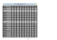
Etisalat telecom requirements<br />
The Table No. 1 below, details the different requirements<br />
for the various types of buildings and types.<br />
Size:<br />
JRC 12 Joint Box<br />
(Etisalat standard)<br />
Location:<br />
Within the property,<br />
near plot line.<br />
Additional Boxes at<br />
all turning points<br />
of lead-in<br />
2 x (4”) inch<br />
pipes/ducts towards<br />
the building and<br />
four x (4”) inch<br />
pipes/ducts towards<br />
the Etisalat Network<br />
A diversity entry<br />
route may also be<br />
provisioned<br />
42U (H) x 800 mm<br />
(W) X 800 mm (D)<br />
Stand alone type<br />
19” equipment<br />
Cabinet<br />
Size:<br />
JRC 12 Joint Box<br />
(Etisalat standard)<br />
Location:<br />
Depending on the<br />
layout<br />
2 x (4”) inch<br />
pipes/ducts towards<br />
the building and<br />
four x (4”) inch<br />
pipes/ducts towards<br />
the Etisalat Network<br />
A diversity entry<br />
route may also be<br />
provisioned<br />
42U (H) x 800 mm<br />
(W) X 800 mm (D)<br />
Stand alone type<br />
19” equipment<br />
Cabinet<br />
Size:<br />
60x60x80 cm with<br />
Grade A cover<br />
Position:<br />
Within land plot<br />
where lead-in<br />
branching to other<br />
blocks end<br />
at turning points<br />
A single x (4”) inch<br />
pipes/ducts to be<br />
extended one meter<br />
outside the plot line<br />
towards Etisalat<br />
Network.<br />
12U (H) x 600 mm<br />
(W) X 515 mm (D)<br />
flush mounted<br />
on wall<br />
7 8<br />
Bldg<br />
Types<br />
Complex of<br />
villas<br />
Single villa Complex of<br />
villas<br />
Bldgs (G+5)<br />
or<br />
Building area<br />
upto 3000 m2<br />
Bldgs (G+5)<br />
or<br />
Bldg floors<br />
(G+6) to (G+10)<br />
or<br />
Bldg of 100<br />
tenants<br />
or<br />
Bldg area<br />
upto 7000 m2<br />
Bldg floors<br />
(G+6) to (G+10)<br />
Bldg floors (G+10)<br />
and more<br />
or<br />
over 100 tenants<br />
or<br />
Bldg area more than<br />
7000 m2<br />
Bldg floors (G+10)<br />
and more<br />
Shopping malls Palaces &<br />
hospitals<br />
Shopping malls Palaces &<br />
hospitals<br />
Group of shops<br />
& sheds<br />
Group of shops<br />
& sheds<br />
Apartment Indoor<br />
Distribution Cabinet<br />
std 19“ Rack<br />
Bldg<br />
Types<br />
Telecom<br />
Requirements<br />
Floor<br />
Distribution Box<br />
Main<br />
Telecom Room<br />
Floor<br />
Telecom Closet<br />
Riser Cable Trays<br />
12U (H) x 600 mm<br />
(W) X 515 mm (D)<br />
flush mounted on<br />
wall<br />
accordance with<br />
Etisalat advise<br />
12U (H) x 600 mm<br />
(W) X 515 mm (D)<br />
flush mounted on<br />
wall, per villa<br />
Single villa Complex of<br />
villas<br />
Size:<br />
One 30x30 x15 cm<br />
box recessed inside<br />
the wall for each<br />
floor.<br />
Location:<br />
Convenient location<br />
with 1 meter free<br />
wall space around<br />
and at a height<br />
between 40-120 cm<br />
above finished<br />
floor level.<br />
Per single villa.<br />
Size: One<br />
30x30x15 cm box<br />
recessed inside the<br />
wall for each floor.<br />
Location:<br />
Convenient location<br />
with one meter free<br />
wall space around<br />
and at a height<br />
between 40-120 cm<br />
above finished<br />
floor level.<br />
No requirements Size:<br />
2x3x3 (LxWxH)<br />
meters for villas<br />
more than<br />
10 numbers<br />
42U (H) x 800 mm<br />
(W) X 800 mm (D)<br />
Stand alone type<br />
19” equipment<br />
Cabinet<br />
Bldgs (G+5)<br />
or<br />
Building area<br />
upto 3000 m2<br />
Size:<br />
One 30x30x15 cm<br />
boxes flush to wall<br />
Location:<br />
To be provided in<br />
each floor Telecom<br />
Closet<br />
Size:<br />
2x3x3 (LxWxH)<br />
meters<br />
Location:<br />
In the ground floor<br />
common area.<br />
No requirements No requirements Size:<br />
Closet (LxWxD)<br />
100x60x60 cm<br />
Location:<br />
In common area<br />
No requirements No requirements 20x5 cm<br />
cable trays<br />
route may also be<br />
provisioned<br />
42U (H) x 800 mm<br />
(W) X 800 mm (D)<br />
Stand alone type<br />
19” equipment<br />
Cabinet<br />
Bldg floors<br />
(G+6) to (G+10)<br />
or<br />
Bldg of 100<br />
tenants<br />
or<br />
Bldg area<br />
upto 7000 m2<br />
Size:<br />
One 30x30x15 cm<br />
box flush to wall<br />
Location:<br />
To be provided in<br />
each floor Telecom<br />
Closet<br />
Size:<br />
3x3x3 (LxWxH)<br />
meters<br />
Location:<br />
In the ground floor<br />
common area.<br />
Size:<br />
Closet (LxWxD)<br />
100x60x60 cm<br />
Location:<br />
In common areas<br />
Table 1 Table 1 (Continued)<br />
20x5 cm<br />
cable trays<br />
route may also be<br />
provisioned<br />
42U (H) x 800 mm<br />
(W) X 800 mm (D)<br />
Stand alone type<br />
19” equipment<br />
Cabinet<br />
Bldg floors (G+10)<br />
and more<br />
or<br />
over 100 tenants<br />
or<br />
Bldg area more than<br />
7000 m2<br />
Size:<br />
One 30x30x15 cm<br />
box flush to wall<br />
Location:<br />
To be provided in<br />
each floor Telecom<br />
Closet<br />
Size:<br />
3x4x3 (LxWxH)<br />
meters<br />
Location:<br />
In the ground floor<br />
common area.<br />
Size:<br />
Closet (LxWxD)<br />
100x60x60 cm<br />
Location:<br />
In common areas<br />
20x5 cm<br />
cable trays<br />
route may also be<br />
provisioned<br />
42U (H) x 800 mm<br />
(W) X 800 mm (D)<br />
Stand alone type<br />
19” equipment<br />
Cabinet<br />
Size:<br />
One 30x30x15 cm<br />
box flush to wall<br />
Location:<br />
To be provided in<br />
each floor Telecom<br />
Closet<br />
Size:<br />
3x4x3 (LxWxH)<br />
meters<br />
Location:<br />
In the ground floor<br />
common area.<br />
Size:<br />
Closet (LxWxD)<br />
100x60x60 cm<br />
Location:<br />
In common area<br />
route may also be<br />
provisioned<br />
42U (H) x 800 mm<br />
(W) X 800 mm (D)<br />
Stand alone type<br />
19” equipment<br />
Cabinet<br />
Shopping malls Palaces &<br />
hospitals<br />
20x5 cm<br />
cable trays<br />
Size:<br />
One 30x30x15 cm<br />
box flush to wall<br />
Location:<br />
To be provided in<br />
each floor Telecom<br />
Closet<br />
Size:<br />
3x4x3 (LxWxH)<br />
meters<br />
Location:<br />
In the ground floor<br />
common area.<br />
Size:<br />
Closet (LxWxD)<br />
100x60x60 cm<br />
Location:<br />
In common areas<br />
20x5 cm<br />
cable trays<br />
12U (H) x 600 mm<br />
(W) X 515 mm (D)<br />
flush mounted<br />
on wall<br />
Group of shops<br />
& sheds<br />
Size:<br />
One 30x30x15 cm box<br />
flush to wall<br />
Location:<br />
To be provided in each<br />
floor Telecom Closet<br />
Size:<br />
2x3x3 (LxWxH) meters<br />
Location:<br />
In the ground floor<br />
common area.<br />
Size:<br />
Closet (LxWxD)<br />
100x60x60 cm<br />
Location:<br />
In common areas<br />
No requirements
<strong>Design</strong> <strong>guide</strong> <strong>www</strong>.<strong>etisalat</strong>.<strong>ae</strong><br />
Structured Cabling System (SCS)<br />
To deliver the services from the ONU, a SCS System on star<br />
topology is required. The minimum requirement is standard<br />
CAT 6 cable with RJ45 connectivity. A SCS design being<br />
project specific, a discussion, with complete details is<br />
recommended with system designers and Etisalat.<br />
However, the following are the general minimum<br />
requirements of structured cabling systems, for provision<br />
of service.<br />
Cabling & termination<br />
Telecommunication cabling<br />
• The cables used for these wiring must comply with<br />
minimum CAT 6 standards<br />
• The planned SCS cable should meet the designed service<br />
requirements within the particular flat level and should<br />
have built-in flexibility, to meet growing needs of the<br />
tenants<br />
• All SCS cables are to be properly labeled and terminated,<br />
in the RJ45 sockets and in-patch panel or in CAT 6<br />
compliant IDC modules by the owners<br />
• Building owner is responsible for replacement of inbuilding<br />
cables and other fixtures, if these become faulty<br />
• Cable diagrams must be submitted to Etisalat for<br />
approval at the design stage and as-built is required on<br />
completion<br />
• Cables and other accessories required for block wiring<br />
may be purchased from any reputable source provided that<br />
the material meets standards<br />
• The name and contact telephone numbers of the SCS<br />
installer, should be labeled at appropriate location<br />
• Completed SCS should be subject to acceptance by<br />
Etisalat. However, the design and performance of the SCS<br />
system should be the responsibility of the installer/owner<br />
• Any upgrading required in the in–building facility,<br />
telecommunication cables, due to either enhanced demand,<br />
change in building status or damage should be provided by<br />
building owner<br />
• The supply and termination of UTP cables on patch<br />
panel or IDC modules and sockets locations should be the<br />
responsibility of the installers/owners<br />
• Etisalat would supply and install, main ODFs, mini ODFs<br />
and optical network units (ONUs). All jumperings and<br />
patchings in the ODFs, patch panels in ONUs would be the<br />
responsibility of Etisalat. Building owners/contractors or<br />
other technicians are totally prohibited to carry out these<br />
functions<br />
Telecommunication socket<br />
All outlets should be Category 6 performance, outlets<br />
mounted in shutters, typically in dual, triple or quad<br />
formation in a single or double gang white faceplate.<br />
All RJ45 outlets should be fitted with spring loaded sliding<br />
shutters to prevent the ingress of dirt and dust.<br />
• Provision for at least one dual socket for<br />
telecommunication services should be made in every room<br />
including kitchen. Conduit with not less than 25 mm<br />
should be connected between the socket locations<br />
• Every socket must be connected with a minimum of four<br />
pair SCS Cat 6 cable, following star topology. In case of<br />
hotel buildings, the provision of telecommunication socket<br />
should also be extended to the bathrooms<br />
• Telecommunication sockets, cables and associated<br />
facilities within the various rooms and premises are to be<br />
provided by the building owner<br />
9 10<br />
Accessories<br />
All accessory plates should be dual or quad white PVC<br />
plated. The use of any special faceplate, which may be<br />
specific to any other manufacturer’s product range, such as<br />
brass finish, etc. should be reviewed.<br />
The choice of outlets distribution, location and type, either<br />
it is single, dual, or quad, the optimum requirements in<br />
each area, ultimate number of outlets in every locations,<br />
flexibility and maximum usage, should be the responsibility<br />
of consultants.<br />
Horizontal subsystem (UTP Cables)<br />
All horizontal cables should be based on the Category 6<br />
performance compliant.<br />
All conductors in each cable should be connected to a<br />
single RJ45 socket at the work area outlets and patch<br />
panel. Each cable should be terminated to maintain the<br />
twists in each pair within 5 mm of the termination. Proper<br />
strain relief should be provided for the cable at the outlets<br />
and patch panel, avoiding strain on the conductors<br />
Colour coding for the termination should be as per the<br />
following table.<br />
Pair Tip Ring<br />
1 White Blue<br />
2 White Orange<br />
3 White Green<br />
4 White Brown<br />
Horizontal cabling<br />
• The physical topology of the horizontal cabling should<br />
be configured as a star with each outlet connected directly<br />
to a flat/apartment distribution box inside the flat or<br />
apartment. No looping of cables from outlet to outlet is<br />
permitted<br />
• The horizontal cabling is to be provided to single, dual,<br />
triple and quad outlets throughout<br />
• The length of cable between the farthest<br />
telecommunications outlet and the distribution box should<br />
not exceed 90 m (295 ft.)<br />
• A minimum of two telecommunications outlets should be<br />
provided for each individual work area. The outlets may be<br />
located with one or more faceplates in the work area<br />
Horizontal pathways<br />
• Horizontal pathways (conduits, sleeves, cable trays,<br />
etc.) are used for taking the cables from the floor<br />
telecommunications room to the telecommunications<br />
outlets in the same floor<br />
• A variety of methods are available and the choice of<br />
selection of method should depend on the purpose of the<br />
floor area to be served (i.e. general office spaces, apartment<br />
dwellings, etc.)<br />
Conduits<br />
• The use of conduits as a horizontal raceway system<br />
should only be considered when the outlet locations are<br />
permanent, the device densities are low and flexibility is<br />
not required<br />
• The minimum size of a conduit pipe used as a<br />
horizontal pathway from the distribution box to the<br />
telecommunications outlet should be 25 mm (1 inch)<br />
• For the conduits, the inside bending radius should always<br />
be at least 10 times the internal diameter
<strong>Design</strong> <strong>guide</strong> <strong>www</strong>.<strong>etisalat</strong>.<strong>ae</strong><br />
• Minimum of one nylon draw wire must be installed in a<br />
conduit<br />
• Pull boxes should be located such that they are readily<br />
accessible at all times. Pull boxes to be spaced at a<br />
maximum of 15 m apart to minimize cable stress during<br />
installation and to provide serviceability in the future<br />
• Conduits must be free from sharp edges, to prevent cable<br />
damage during and subsequent to pulling<br />
• Conduits protruding through a floor should be<br />
terminated; a minimum of 50 mm from the floor to prevent<br />
water or other liquids from flowing into the conduits<br />
Maximum number of UTP cables inside a conduit,<br />
recommended for the installation of a Structured Cabling<br />
System is as follows:<br />
Conduit trade Internal dia No. of Cat<br />
size (mm) 6 cables<br />
1” 25.40 7<br />
11 /4” 34.04 13<br />
11 /2” 39.88 18<br />
2” 51.31 30<br />
Cable capacities in trays conduits<br />
When the internal cable trays, risers and ladders, etc. are<br />
designed, supplied and installed by others, the maximum<br />
number of UTP cables, recommended to be installed on<br />
a tray as shown; however this need to be reduced in the<br />
case of bends and crossovers. The formula applied is that<br />
for every 25 mm x 25 mm cross section, 8 cables can be<br />
accommodated. No truncking or cable tray should be more<br />
than 75% full on installation.<br />
Cable tray size Truncking size No. of UTP<br />
(mm) (mm) cables<br />
50x50 50x50 30<br />
75x50 50x75 45<br />
100x50 50x100 60<br />
100x50 75x75 67<br />
150x 50 75x100 90<br />
200x50 100x100 120<br />
300x 50 150x150 180<br />
450x50 - 360<br />
900x50 - 540<br />
Where a FO cable block wiring is considered, a very careful<br />
consideration must be taken, while designing the system.<br />
The owner should be responsible for the design, supply and<br />
maintenance of all related items.<br />
Indoor equipment cabinet 19”<br />
Depending upon the termination and patch panel<br />
requirement, and to accommodate other active and passive<br />
equipment, a cabinet with standard 19” rack is required,<br />
generally complying with the following:-<br />
A) Free standing types<br />
Recommended for high-rise buildings, shopping malls,<br />
hospitals, airports, large commercial establishments, etc.<br />
The cabinets should be:<br />
• 42U 800 mm wide x 800 mm deep 19” equipment cabinet<br />
• Glass front door with provision for air circulation<br />
• Steel rear door<br />
• Jacking feet<br />
• Horizontal cable management<br />
• Vertical cable management<br />
• Bonded to a local earth point<br />
B) Wall-mounted type cabinets<br />
These are recommended for flats, villas, shops, etc. and<br />
should be provided flush with wall, at a common location<br />
where all SCS cables, patch panels/IDC modules, fibres,<br />
power and ONU equipment are proposed to be installed.<br />
The cabinet should be exclusive for Etisalat use and no<br />
access to others should be allowed.<br />
• 12U – 22U 600 mm wide x 515 mm deep 19” wiring/<br />
equipment cabinet<br />
• Glass front door with provision for air circulation<br />
• Vertical cable management<br />
• Bonded to a local earth point<br />
We recommend that the proposed locations of the cabinets<br />
have sufficient space around the cabinets to allow access<br />
to installation and maintenance and should be located in<br />
central locations, where all the terminations of the SCS<br />
cables on patch panels/IDC modules and fibre termination<br />
and ONUs, power socket and battery back up, should be<br />
installed.<br />
11 12<br />
Patching<br />
The design of patch frame layouts is critical to create a<br />
high level of manageability within a compact cabinet,<br />
while maintaining effective operations when used by the<br />
customer.<br />
We recommend all horizontal UTP cabling should be<br />
terminated in a 12 or 24 port patch panel, placed inside<br />
the wall or floor cabinet. Alternatively, Cat 6 compliant IDC<br />
modules can also be used.<br />
Voice services can be fed from the services patch panel<br />
directly to the user outlet using standard 1 pair patch<br />
cords.<br />
Labeling<br />
Label elements<br />
All floor outlets, patch frames and horizontal cables should<br />
be labeled. A typewritten standard labeling system is<br />
recommended. The labeling scheme shall be agreed on with<br />
the clients’ telecom team.<br />
Horizontal cable labels<br />
Label all horizontal cables at both ends using a selflaminating,<br />
wrap around label.<br />
User outlet labels<br />
Each RJ45 user outlet should be labeled with a unique<br />
identifier, typically using the agreed scheme.<br />
Under-floor systems<br />
• For general office spaces, an under-floor raceway system<br />
should be used for maximum flexibility<br />
• In multi-channel layouts, separate raceways must be<br />
used for telecommunications and electrical power to<br />
reduce electromagnetic interference. The dividers for<br />
separation of compartments in the raceway should be<br />
bonded to ground<br />
Main elements of under-floor raceway<br />
systems<br />
Distribution raceway<br />
• Distribution raceway provides a pathway for the cables<br />
from the feeder raceway to the work areas. The minimum
<strong>Design</strong> <strong>guide</strong> <strong>www</strong>.<strong>etisalat</strong>.<strong>ae</strong><br />
size of the distribution raceway should be 30 mm height x<br />
60 mm width of cross-sectional area. The same size must<br />
be used for every (multi-channel) layout<br />
Feeder raceway<br />
• Feeder raceway provides a pathway for the cables from<br />
the distribution box in the floor telecommunications room<br />
to the distribution raceways. The minimum size of the<br />
feeder raceway should be 40 mm height x 200 mm width<br />
of cross-sectional area. The same size must be used for<br />
every (multi-channel) layout<br />
• The feeder raceways starting point in the floor<br />
telecommunications room must be adjacent to the<br />
distribution box. The Feeder raceway should end at the last<br />
distribution raceway it is serving<br />
Access unit<br />
• The access unit provides access at the point of<br />
intersection of the feeder and the distribution raceways<br />
Cable trays<br />
• Cable trays are mostly used for floors with raised tiles or<br />
floorings<br />
• As a general <strong>guide</strong>line, cable trays that intersect must be<br />
provided with a transitional bend radius of 150 mm in all<br />
directions<br />
• Exposed sheet metal edges must be provided with<br />
bushings or other means of protection such that cables will<br />
not be damaged during or after installation. Since cable<br />
trays are usually metallic, all sharp edges, burrs and screw<br />
tips that may come into contact with cabling should be<br />
removed<br />
• The minimum access space between the sub-floor and<br />
the underside of the floor tile should be minimum<br />
150 mm (6 in)<br />
Etisalat should be consulted in the initial design stage to<br />
decide on the requirements if the building is designed for<br />
office use.<br />
Protection from<br />
electromagnetic interference<br />
The following requirements apply to UTP cabling,<br />
as pathways and spaces used to carry or house<br />
telecommunications cabling.<br />
• The proximity of cabling to electrical facilities and<br />
equipment that generate high levels of electromagnetic<br />
interference (EMI) should be taken into account for<br />
metallic cabling<br />
• Sources of EMI include: power cables, photocopy<br />
equipment, electric motors, transformers, fluorescent<br />
lighting, arc welders and induction heaters, etc.<br />
To avoid EMI, the telecommunications pathways, spaces<br />
and metallic cables should be installed with the following<br />
clearances:<br />
41.2 m (4 ft) from large motors or transformers<br />
40.3 m (1 ft) from conduit and cables used for electrical<br />
power distribution<br />
412 cm (5 in) from fluorescent lighting<br />
• Pathways and metallic cables should cross perpendicular<br />
to fluorescent lighting and electrical power cables or<br />
conduits<br />
Separation distance from power source<br />
During the design stages, separation of power and the<br />
Structured Cabling Systems (SCS) must be considered.<br />
Unshielded data cables should not be installed near sources<br />
of electromagnetism. The <strong>guide</strong>lines are listed on the<br />
next page.<br />
Typical building environment<br />
Minimum separation distance from power source
<strong>Design</strong> <strong>guide</strong> <strong>www</strong>.<strong>etisalat</strong>.<strong>ae</strong><br />
• Direct sunlight should not fall in the PBX room. Curtains/<br />
screens are to be provided for the windows if any<br />
• Power conduit and telecom cable conduit must be<br />
separate<br />
Electrical requirements<br />
• A minimum of two 13 amp 240 v A/C main outlets (via)<br />
UPS system should be provided. The actual mains power<br />
requirements will depend on the size and type of the PBX<br />
• The room should be provided with an earth not more<br />
than 5 ohms<br />
• Anti-static flooring should be provided, including the<br />
battery room<br />
• The rooms must be provided with an emergency light,<br />
a smoke detector and a fire alarm<br />
PABX can be installed in the main telecom room in the case<br />
of a single owner.<br />
Important note<br />
1) This design <strong>guide</strong> explains in general, all Etisalat<br />
requirements that will facilitate the provision of<br />
telecommunication services to new buildings, yet the<br />
requirements indicated in the ‘NOC’ (No Objection<br />
Certificate) should be fully complied.<br />
2) Architects/consultants/designers must liaise with<br />
Etisalat at the design stage and obtain Etisalat approval on<br />
the final design drawings.<br />
3) Minimum two sets of telephone design drawings must<br />
be submitted for study and approval, before tendering.<br />
4) Where deviations/comments/amendments are advised<br />
on the design, drawings must be corrected and<br />
re-submitted for approval.<br />
5) One set of approved ‘As-Built’ drawings must be<br />
submitted along with the building completion certificate,<br />
which will be certified by Etisalat.<br />
6) Etisalat’s responsibility is limited to provision and<br />
installation of ODFs, termination of fibres, patching/<br />
jumpering works and Optical Network Units (ONUs).<br />
7) The owners are responsible for supply and installation<br />
of all internal FO cables from ODF (main telecom room)<br />
to ONU (customer premises) locations, provision of wall<br />
mounted or stand alone cabinets to accommodate ONU,<br />
power, patch panels, etc. and complete structured cabling<br />
system.<br />
8) The indoor drop 2 F fiber cables, should be from a<br />
popular brand and make, conforming to ITU standard G 652<br />
single mode fiber standards.<br />
9) On completion of the requirements, any comments<br />
and snags advised by Etisalat building inspector, must be<br />
attended to by the contractor or owner of the building<br />
soon, to avoid delays in the issuance of the building<br />
completion certificate.<br />
List of annexures<br />
Annexure I type of entry box<br />
(JRC 4 & JRC 12)<br />
Annexure II typical examples<br />
15 16
<strong>Design</strong> <strong>guide</strong> <strong>www</strong>.<strong>etisalat</strong>.<strong>ae</strong><br />
1 مقر قحلملا<br />
Annexure 1<br />
17 18
<strong>Design</strong> <strong>guide</strong> <strong>www</strong>.<strong>etisalat</strong>.<strong>ae</strong><br />
1 مقر قحلملا<br />
Annexure 1<br />
Typical telecom requirement in villas<br />
2 مقر قحلملا<br />
Annexure 2<br />
19 20
<strong>Design</strong> <strong>guide</strong> <strong>www</strong>.<strong>etisalat</strong>.<strong>ae</strong><br />
Typical telecom requirement in multi-storey building<br />
TYPICAL TELECOM REQUIREMENT IN VILLAS<br />
2 مقر قحلملا<br />
Annexure 2<br />
21 22