1 table of contents specifications list division 0
1 table of contents specifications list division 0
1 table of contents specifications list division 0
- No tags were found...

Create successful ePaper yourself
Turn your PDF publications into a flip-book with our unique Google optimized e-Paper software.
RME VARIOUS SITES<br />
JOSE LUIS GARCIA<br />
672-12-118 CONSULTING ENGINEERS<br />
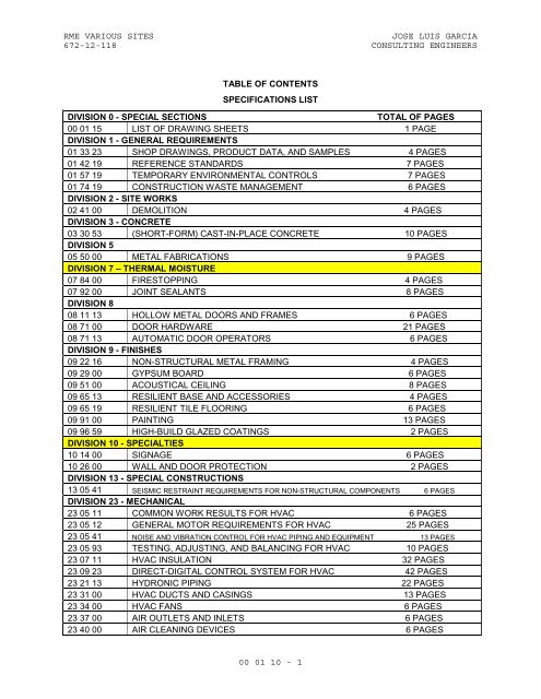
TABLE OF CONTENTS<br />
SPECIFICATIONS LIST<br />
DIVISION 0 - SPECIAL SECTIONS<br />
TOTAL OF PAGES<br />
00 01 15 LIST OF DRAWING SHEETS 1 PAGE<br />
DIVISION 1 - GENERAL REQUIREMENTS<br />
01 33 23 SHOP DRAWINGS, PRODUCT DATA, AND SAMPLES 4 PAGES<br />
01 42 19 REFERENCE STANDARDS 7 PAGES<br />
01 57 19 TEMPORARY ENVIRONMENTAL CONTROLS 7 PAGES<br />
01 74 19 CONSTRUCTION WASTE MANAGEMENT 6 PAGES<br />
DIVISION 2 - SITE WORKS<br />
02 41 00 DEMOLITION 4 PAGES<br />
DIVISION 3 - CONCRETE<br />
03 30 53 (SHORT-FORM) CAST-IN-PLACE CONCRETE 10 PAGES<br />
DIVISION 5<br />
05 50 00 METAL FABRICATIONS 9 PAGES<br />
DIVISION 7 – THERMAL MOISTURE<br />
07 84 00 FIRESTOPPING 4 PAGES<br />
07 92 00 JOINT SEALANTS 8 PAGES<br />
DIVISION 8<br />
08 11 13 HOLLOW METAL DOORS AND FRAMES 6 PAGES<br />
08 71 00 DOOR HARDWARE 21 PAGES<br />
08 71 13 AUTOMATIC DOOR OPERATORS 6 PAGES<br />
DIVISION 9 - FINISHES<br />
09 22 16 NON-STRUCTURAL METAL FRAMING 4 PAGES<br />
09 29 00 GYPSUM BOARD 6 PAGES<br />
09 51 00 ACOUSTICAL CEILING 8 PAGES<br />
09 65 13 RESILIENT BASE AND ACCESSORIES 4 PAGES<br />
09 65 19 RESILIENT TILE FLOORING 6 PAGES<br />
09 91 00 PAINTING 13 PAGES<br />
09 96 59 HIGH-BUILD GLAZED COATINGS 2 PAGES<br />
DIVISION 10 - SPECIALTIES<br />
10 14 00 SIGNAGE 6 PAGES<br />
10 26 00 WALL AND DOOR PROTECTION 2 PAGES<br />
DIVISION 13 - SPECIAL CONSTRUCTIONS<br />
13 05 41 SEISMIC RESTRAINT REQUIREMENTS FOR NON-STRUCTURAL COMPONENTS 6 PAGES<br />
DIVISION 23 - MECHANICAL<br />
23 05 11 COMMON WORK RESULTS FOR HVAC 6 PAGES<br />
23 05 12 GENERAL MOTOR REQUIREMENTS FOR HVAC 25 PAGES<br />
23 05 41 NOISE AND VIBRATION CONTROL FOR HVAC PIPING AND EQUIPMENT 13 PAGES<br />
23 05 93 TESTING, ADJUSTING, AND BALANCING FOR HVAC 10 PAGES<br />
23 07 11 HVAC INSULATION 32 PAGES<br />
23 09 23 DIRECT-DIGITAL CONTROL SYSTEM FOR HVAC 42 PAGES<br />
23 21 13 HYDRONIC PIPING 22 PAGES<br />
23 31 00 HVAC DUCTS AND CASINGS 13 PAGES<br />
23 34 00 HVAC FANS 6 PAGES<br />
23 37 00 AIR OUTLETS AND INLETS 6 PAGES<br />
23 40 00 AIR CLEANING DEVICES 6 PAGES<br />
00 01 10 - 1
RME VARIOUS SITES<br />
JOSE LUIS GARCIA<br />
672-12-118 CONSULTING ENGINEERS<br />
23 74 13 CENTRAL-STATION AIR-HANDLING UNITS 12 PAGES<br />
23 82 16 AIR COILS 5 PAGES<br />
DIVISION 26 - ELECTRICAL<br />
26 05 11 REQUIREMENTS FOR ELECTRICAL INSTALLATIONS 9 PAGES<br />
LOW-VOLTAGE ELECTRICAL POWER CONDUCTORS AND CABLES (600 VOLTS<br />
26 05 21 AND BELOW)<br />
7 PAGES<br />
26 05 26 GROUNDING AND BONDING FOR ELECTRICAL SYSTEMS 8 PAGES<br />
26 05 33 RACEWAY AND BOXES FOR ELECTRICAL SYSTEMS 12 PAGES<br />
26 24 16 PANELBOARDS 6 PAGES<br />
26 29 11 MOTOR STARTERS 12 PAGES<br />
26 29 21 DISCONNECT SWITCHES 3 PAGES<br />
00 01 10 - 2
RME VARIOUS SITES<br />
JOSE LUIS GARCIA<br />
672-12-118 CONSULTING ENGINEERS<br />
SECTION 00 01 15<br />
LIST OF DRAWING SHEETS<br />
The drawings <strong>list</strong>ed below accompanying this specification form a part <strong>of</strong><br />
the contract.<br />
Sheet No.<br />
Drawing Title<br />
T-1 Title Sheet & Index <strong>of</strong> Drawings<br />
MECHANICAL<br />
AC-1 General Requirements<br />
AC-2 General Requirements<br />
AC-3 Basement Level AC Plan<br />
AC-4 First Floor AC Plan<br />
AC-5 Ro<strong>of</strong> Level AC Plan<br />
AC-6 Ponce Clinic AC Floor Plan<br />
AC-7 Ponce Clinic AC Ro<strong>of</strong> Plan<br />
AC-8 SPD ETO Existing Exhaust System<br />
AC-9 SPD New ETO Exhaust Sys. & AC Ro<strong>of</strong> Plan<br />
AC-10 Existing Podiatry Clinic ACV System<br />
AC-11 New Podiatry Clinic ACV System<br />
AC-12 Existing Physical Therapy Clinic ACV System<br />
AC-13 New Physical Therapy Clinic ACV System<br />
AC-14 VA Ponce Exist. & New Receiving and Sterile/Clean Sto. Rm. ACV Sys.<br />
AC-15 VA Ponce New AC Ro<strong>of</strong> Plan<br />
AC-16 SPD & ETO New Air Flow & Control Diagram<br />
AC-17 Podiatry Clinic New Air Flow & Control Diagram<br />
AC-18 Physical Therapy, New Therapy Pool & New Air Flow & Control Diagram<br />
AC-19 VA Ponce Receiving and Sterile/Clean Sto. Rm. Air Flow & Control Diagram<br />
AC-20 San Juan Podiatry Clinic AC Schedules and Notes<br />
AC-21 Physical Therapy Clinic AC Schedules and Notes<br />
AC-22 SPD ETO Clinic AC Schedules and Notes<br />
AC-23 VA Ponce Receiving and Sterile/Clean Sto. Rm. AC Schedules & Notes<br />
AC-24 General Details<br />
AC-25 General Details<br />
ELECTRICAL<br />
E-1 Legend Notes and Schedules<br />
E-2 First Floor Electrical Plan<br />
E-3 Ro<strong>of</strong> Level Electrical<br />
E-4 VA Ponce New Ro<strong>of</strong> Plan<br />
E-5 VA Ponce New Electrical Ro<strong>of</strong> Plan<br />
E-6 VA Ponce Electrical Room, One Line Diagram and Schedules<br />
Architectural<br />
A-1 Demolition Floor Plan<br />
A-2 Partition Floor Plan<br />
A-3 Reflected Ceiling Plan and Partial Ro<strong>of</strong> Plan<br />
A-4 Door, Window and Wall Details<br />
A-5 Wall and Miscellaneous Details<br />
A-6 Seismic Resistant Ceiling Details<br />
00 01 15 - 1
RME VARIOUS SITES<br />
672-12-118<br />
SECTION 01 00 00<br />
GENERAL REQUIREMENTS<br />
TABLE OF CONTENTS<br />
1.1 GENERAL INTENTION..................................................................................................................1<br />
1.2 STATEMENT OF BID ITEM(S) ...................................................................................................2<br />
1.3 SPECIFICATIONS AND DRAWINGS FOR CONTRACTOR ........................................................2<br />
1.4 construction security requirements............................................................................2<br />
1.5 FIRE SAFETY...................................................................................................................................4<br />
1.6 OPERATIONS AND STORAGE AREAS..........................................................................................8<br />
1.7 ALTERATIONS.................................................................................................................................12<br />
1.8 INFECTION PREVENTION MEASURES......................................................................................14<br />
1.9 DISPOSAL AND RETENTION ......................................................................................................17<br />
1.10 PROTECTION OF EXISTING VEGETATION, STRUCTURES, EQUIPMENT,<br />
UTILITIES, AND IMPROVEMENTS....................................................................................................17<br />
1.11 RESTORATION ..............................................................................................................................19<br />
1.12 PHYSICAL DATA .........................................................................................................................20<br />
1.13 As-Built Drawings................................................................................................................20<br />
1.14 USE OF ROADWAYS.....................................................................................................................21<br />
1.15 TEMPORARY USE OF MECHANICAL AND ELECTRICAL EQUIPMENT ............................21<br />
1.16 TEMPORARY USE OF EXISTING ELEVATORS.....................................................................22<br />
1.17 TEMPORARY TOILETS................................................................................................................23<br />
1.18 AVAILABILITY AND USE OF UTILITY SERVICES.........................................................23<br />
1.19 TESTS.............................................................................................................................................25<br />
1.20 INSTRUCTIONS............................................................................................................................26<br />
1.21 EQUIPMENT ...................................................................................................................................27<br />
i
RME VARIOUS SITES<br />
672-12-118<br />
1.22 CONSTRUCTION SIGN................................................................................................................28<br />
1.23 SAFETY SIGN ..............................................................................................................................28<br />
ii
08-10<br />
SECTION 01 00 00<br />
GENERAL REQUIREMENTS<br />
1.1 GENERAL INTENTION<br />
A. Contractor shall completely prepare site for building operations,<br />
including demolition and removal <strong>of</strong> existing structures, and furnish<br />
labor and materials and perform work for the RME VARIOUS SITES HVAC<br />
UPGRADE as required by drawings and <strong>specifications</strong>.<br />
B. Visits to the site by Bidders may be made only by appointment with the<br />
Contracting Officer and/or VA Project Manager/COR assigned. Refer to bid<br />
instructions.<br />
C. Offices <strong>of</strong> JLG CONSULTING ENGINEERING P.S.C., as Architect-Engineers,<br />
will render certain technical services during construction. Such<br />
services shall be considered as advisory to the Government and shall not<br />
be construed as expressing or implying a contractual act <strong>of</strong> the<br />
Government without affirmations by Contracting Officer or his duly<br />
authorized representative.<br />
E. All employees <strong>of</strong> general contractor and subcontractors shall comply with<br />
VA security management program and obtain permission <strong>of</strong> the VA police,<br />
be identified by project and employer, and restricted from unauthorized<br />
access.<br />
F. Prior to commencing work, general contractor shall provide pro<strong>of</strong> that a<br />
OSHA certified “competent person” (CP) (29 CFR 1926.20(b)(2) will<br />
maintain a presence at the work site whenever the general or<br />
subcontractors are present.<br />
G. Training:<br />
1. All employees <strong>of</strong> general contractor or subcontractors shall have the<br />
10-hour OSHA certified Construction Safety course and /or other<br />
relevant competency training, as determined by VA CP with input from<br />
the ICRA team.<br />
2. Submit training records <strong>of</strong> all such employees for approval before the<br />
start <strong>of</strong> work.<br />
01 00 00 -1
08-10<br />
1.2 STATEMENT OF BID ITEM(S)<br />
A. ITEM I, GENERAL CONSTRUCTION: Provide HVAC upgrades to three areas on<br />
two different sites: San Juan VAMC Building and Ponce Outpatient Clinic.<br />
The areas included in this project are: Podiatry Clinic and Physical<br />
Therapy Room at San Juan VAMC; and the SPD Primary at Ponce OPC.<br />
Work includes general construction, alterations, mechanical and<br />
electrical work, utility systems, necessary removal <strong>of</strong> existing<br />
structures and construction and certain other items.<br />
1.3 SPECIFICATIONS AND DRAWINGS FOR CONTRACTOR<br />
A. DURING PRE-AWARD PHASE, 1 digital copy <strong>of</strong> all <strong>specifications</strong> and<br />
drawings will be furnished in .pdf and/or .dwg format. Any other format<br />
required by selected contractor will be discussed with CO/COTR.<br />
B. Additional sets <strong>of</strong> drawings may be made by the Contractor, at<br />
Contractor's expense, from reproducible sepia prints furnished by<br />
Issuing Office. Such sepia prints shall be returned to the Issuing<br />
Office immediately after printing is completed.<br />
1.4 CONSTRUCTION SECURITY REQUIREMENTS<br />
A. Security Plan:<br />
1. The security plan defines both physical and administrative security<br />
procedures that will remain effective for the entire duration <strong>of</strong> the<br />
project.<br />
2. The General Contractor is responsible for assuring that all subcontractors<br />
working on the project and their employees also comply<br />
with these regulations.<br />
B. Security Procedures:<br />
01 00 00 -2
08-10<br />
1. General Contractor’s employees shall not enter the project site<br />
without appropriate badge. They may also be subject to inspection <strong>of</strong><br />
their personal effects when entering or leaving the project site.<br />
2. For working outside the “regular hours” as defined in the contract,<br />
The General Contractor shall give 3 days notice to the Contracting<br />
Officer so that security arrangements can be provided for the<br />
employees. This notice is separate from any notices required for<br />
utility shutdown described later in this section.<br />
3. No photography <strong>of</strong> VA premises is allowed without written permission<br />
<strong>of</strong> the Contracting Officer.<br />
4. VA reserves the right to close down or shut down the project site and<br />
order General Contractor’s employees <strong>of</strong>f the premises in the event <strong>of</strong><br />
a national emergency. The General Contractor may return to the site<br />
only with the written approval <strong>of</strong> the Contracting Officer.<br />
C. Key Control:<br />
1. The General Contractor shall provide duplicate keys and lock<br />
combinations to the VA Project Manager and Graphic Control for the<br />
purpose <strong>of</strong> security inspections <strong>of</strong> every area <strong>of</strong> project including<br />
tool boxes and parked machines and takes any emergency action.<br />
2. The General Contractor shall turn over all permanent lock cylinders<br />
to the VA locksmith for permanent installation. See Section 08 71 00,<br />
DOOR HARDWARE and coordinate.<br />
D. Document Control:<br />
1. Before starting any work, the General Contractor/Sub Contractors<br />
shall submit an electronic security memorandum describing the<br />
approach to following goals and maintaining confidentiality <strong>of</strong><br />
“sensitive information”.<br />
2. The General Contractor is responsible for safekeeping <strong>of</strong> all<br />
drawings, project manual and other project information. This<br />
information shall be shared only with those with a specific need to<br />
accomplish the project.<br />
4. Certain documents, sketches, videos or photographs and drawings may<br />
be marked “Law Enforcement Sensitive” or “Sensitive Unclassified”.<br />
Secure such information in separate containers and limit the access<br />
01 00 00 -3
08-10<br />
to only those who will need it for the project. Return the<br />
information to the Contracting Officer upon request.<br />
5. These security documents shall not be removed or transmitted from the<br />
project site without the written approval <strong>of</strong> Contracting Officer.<br />
6. All paper waste or electronic media such as CD’s and diskettes shall<br />
be shredded and destroyed in a manner accep<strong>table</strong> to the VA.<br />
7. Notify Contracting Officer and Site Security Officer immediately when<br />
there is a loss or compromise <strong>of</strong> “sensitive information”.<br />
8. All electronic information shall be stored in specified location<br />
following VA standards and procedures using an Engineering Document<br />
Management S<strong>of</strong>tware (EDMS).<br />
a. Security, access and maintenance <strong>of</strong> all project drawings, both<br />
scanned and electronic shall be performed and tracked through the<br />
EDMS system.<br />
b. “Sensitive information” including drawings and other documents may<br />
be attached to e-mail provided all VA encryption procedures are<br />
followed.<br />
E. Motor Vehicle Restrictions<br />
1. Vehicle authorization request shall be required for any vehicle<br />
entering the site and such request shall be submitted 24 hours before<br />
the date and time <strong>of</strong> access. Access shall be restricted to picking up<br />
and dropping <strong>of</strong>f materials and supplies.<br />
2. Separate permits shall be issued for General Contractor and its<br />
employees for parking in designated areas only.<br />
1.5 FIRE SAFETY<br />
A. Applicable Publications: Publications <strong>list</strong>ed below form part <strong>of</strong> this<br />
Article to extent referenced. Publications are referenced in text by<br />
basic designations only.<br />
01 00 00 -4
08-10<br />
1. American Society for Testing and Materials (ASTM):<br />
E84-2008.............Surface Burning Characteristics <strong>of</strong> Building<br />
Materials<br />
2. National Fire Protection Association (NFPA):<br />
10-2006..............Standard for Por<strong>table</strong> Fire Extinguishers<br />
30-2007..............Flammable and Combustible Liquids Code<br />
51B-2003.............Standard for Fire Prevention During Welding,<br />
Cutting and Other Hot Work<br />
70-2007..............National Electrical Code<br />
241-2004.............Standard for Safeguarding Construction,<br />
Alteration, and Demolition Operations<br />
3. Occupational Safety and Health Administration (OSHA):<br />
29 CFR 1926..........Safety and Health Regulations for Construction<br />
B. Fire Safety Plan: Establish and maintain a fire protection program in<br />
accordance with 29 CFR 1926. Prior to start <strong>of</strong> work, prepare a plan<br />
detailing project-specific fire safety measures, including periodic<br />
status reports, and submit to VA Project Manager and Facility Safety<br />
Engineer for review for compliance with contract requirements in<br />
accordance with Section 01 33 23, SHOP DRAWINGS, PRODUCT DATA AND<br />
SAMPLES Prior to any worker for the contractor or subcontractors<br />
beginning work, they shall undergo a safety briefing provided by the<br />
general contractor’s competent person per OSHA requirements. This<br />
briefing shall include information on the construction limits, VAMC<br />
safety guidelines, means <strong>of</strong> egress, break areas, work hours, locations<br />
<strong>of</strong> restrooms, use <strong>of</strong> VAMC equipment, etc. Documentation shall be<br />
provided to the Engineer or VA Project Manager that individual has<br />
undergone contractor’s safety briefing.<br />
C. Site and Building Access: Maintain free and unobstructed access to<br />
facility emergency services and for fire, police and other emergency<br />
response forces in accordance with NFPA 241.<br />
D. Separate temporary facilities, such as trailers, storage sheds, and<br />
dumpsters, from existing buildings and new construction by distances in<br />
01 00 00 -5
08-10<br />
accordance with NFPA 241. For small facilities with less than 6 m (20<br />
feet) exposing overall length, separate by 3m (10 feet).<br />
E. Temporary Construction Partitions:<br />
1. Install and maintain temporary construction partitions to provide<br />
smoke-tight separations between construction areas and adjoining<br />
areas. Construct partitions <strong>of</strong> gypsum board or treated plywood (flame<br />
spread rating <strong>of</strong> 25 or less in accordance with ASTM E84) on both<br />
sides <strong>of</strong> fire retardant treated wood or metal steel studs. Extend the<br />
partitions through suspended ceilings to floor slab deck or ro<strong>of</strong>.<br />
Seal joints and penetrations. At door openings, install Class C, ¾<br />
hour fire/smoke rated doors with self-closing devices.<br />
2. Install one-hour fire-rated temporary construction partitions as<br />
shown on drawings to maintain integrity <strong>of</strong> existing exit stair<br />
enclosures, exit passageways, fire-rated enclosures <strong>of</strong> hazardous<br />
areas, horizontal exits, smoke barriers, vertical shafts and openings<br />
enclosures.<br />
3. Close openings in smoke barriers and fire-rated construction to<br />
maintain fire ratings. Seal penetrations with <strong>list</strong>ed throughpenetration<br />
firestop materials in accordance with Section 07 84 00,<br />
FIRESTOPPING.<br />
F. Temporary Heating and Electrical: Install, use and maintain<br />
installations in accordance with 29 CFR 1926, NFPA 241 and NFPA 70.<br />
G. Means <strong>of</strong> Egress: Do not block exiting for occupied buildings, including<br />
paths from exits to roads. Minimize disruptions and coordinate with VA<br />
Project Manager and facility Safety Engineer/Officer.<br />
H. Egress Routes for Construction Workers: Maintain free and unobstructed<br />
egress. Inspect daily and report findings and corrective actions weekly<br />
to VA Project Manager and facility Safety Engineer/Officer.<br />
I. Fire Extinguishers: Provide and maintain extinguishers in construction<br />
areas and temporary storage areas in accordance with 29 CFR 1926, NFPA<br />
241 and NFPA 10.<br />
J. Flammable and Combustible Liquids: Store, dispense and use liquids in<br />
accordance with 29 CFR 1926, NFPA 241 and NFPA 30.<br />
01 00 00 -6
08-10<br />
K. Existing Fire Protection: Do not impair automatic sprinklers, smoke and<br />
heat detection, and fire alarm systems, except for portions immediately<br />
under construction, and temporarily for connections. Provide fire watch<br />
for impairments more than 4 hours in a 24-hour period. Request<br />
interruptions in accordance with Article, OPERATIONS AND STORAGE AREAS,<br />
and coordinate with VA Project Manager and facility Safety<br />
Engineer/Officer all existing or temporary fire protection systems (fire<br />
alarms, sprinklers) located in construction areas shall be tested as<br />
coordinated with the medical center. Parameters for the testing and<br />
results <strong>of</strong> any tests performed shall be recorded by the medical center<br />
and copies provided to the VA Project Manager.<br />
L. Smoke Detectors: Prevent accidental operation. Remove temporary covers<br />
at end <strong>of</strong> work operations each day. Coordinate with VA Project Manager<br />
and facility Safety Engineer/Officer.<br />
M. Hot Work: Perform and safeguard hot work operations in accordance with<br />
NFPA 241 and NFPA 51B. Coordinate with VA Project Manager and facility<br />
Safety Engineer/Officer. Obtain permits from VA Project Manager and<br />
facility Safety Engineer/Officer at least 48 hours in advance. Designate<br />
contractor's responsible project-site fire prevention program manager to<br />
permit hot work.<br />
N. Fire Hazard Prevention and Safety Inspections: Inspect entire<br />
construction areas weekly. Coordinate with, and report findings and<br />
corrective actions weekly to VA Project Manager and facility Safety<br />
Engineer/Officer.<br />
O. Smoking: Smoking is prohibited in and adjacent to construction areas<br />
inside existing buildings and additions under construction. In separate<br />
and detached buildings under construction, smoking is prohibited except<br />
in designated smoking rest areas.<br />
P. Dispose <strong>of</strong> waste and debris in accordance with NFPA 241. Remove from<br />
buildings daily.<br />
Q. Perform other construction, alteration and demolition operations in<br />
accordance with 29 CFR 1926.<br />
R. If required, submit documentation to the VA Project Manager that<br />
personnel have been trained in the fire safety aspects <strong>of</strong> working in<br />
areas with impaired structural or compartmentalization features.<br />
01 00 00 -7
08-10<br />
1.6 OPERATIONS AND STORAGE AREAS<br />
A. The Contractor shall confine all operations (including storage <strong>of</strong><br />
materials) on Government premises to areas authorized or approved by the<br />
Contracting Officer. The Contractor shall hold and save the Government,<br />
its <strong>of</strong>ficers and agents, free and harmless from liability <strong>of</strong> any nature<br />
occasioned by the Contractor's performance.<br />
B. Temporary buildings (e.g., storage sheds, shops, <strong>of</strong>fices) and utilities<br />
may be erected by the Contractor only with the approval <strong>of</strong> the<br />
Contracting Officer and shall be built with labor and materials<br />
furnished by the Contractor without expense to the Government. The<br />
temporary buildings and utilities shall remain the property <strong>of</strong> the<br />
Contractor and shall be removed by the Contractor at its expense upon<br />
completion <strong>of</strong> the work. With the written consent <strong>of</strong> the Contracting<br />
Officer, the buildings and utilities may be abandoned and need not be<br />
removed.<br />
C. The Contractor shall, under regulations prescribed by the Contracting<br />
Officer, use only established roadways, or use temporary roadways<br />
constructed by the Contractor when and as authorized by the Contracting<br />
Officer. When materials are transported in prosecuting the work,<br />
vehicles shall not be loaded beyond the loading capacity recommended by<br />
the manufacturer <strong>of</strong> the vehicle or prescribed by any Federal, State, or<br />
local law or regulation. When it is necessary to cross curbs or<br />
sidewalks, the Contractor shall protect them from damage. The Contractor<br />
shall repair or pay for the repair <strong>of</strong> any damaged curbs, sidewalks, or<br />
roads.<br />
D. Working space and space available for storing materials shall be as<br />
determined by the VA Project Manager and Planning Section Personnel.<br />
E. Workmen are subject to rules <strong>of</strong> Medical Center applicable to their<br />
conduct.<br />
F. Execute work so as to interfere as little as possible with normal<br />
functioning <strong>of</strong> VACHS Medical Center as a whole, including operations <strong>of</strong><br />
utility services, fire protection systems and any existing equipment,<br />
and with work being done by others. Use <strong>of</strong> equipment and tools that<br />
transmit vibrations and noises through the building structure, are not<br />
permitted in buildings that are occupied, during construction, jointly<br />
01 00 00 -8
08-10<br />
by patients or medical personnel, and Contractor's personnel, except as<br />
permitted by VA Project Manager where required by limited working space.<br />
1. Do not store materials and equipment in other than assigned areas.<br />
2. Schedule delivery <strong>of</strong> materials and equipment to immediate<br />
construction working areas within buildings in use by Department <strong>of</strong><br />
Veterans Affairs in quantities sufficient for not more than two work<br />
days. Provide unobstructed access to VACHS Medical Center areas<br />
required to remain in operation.<br />
3. Where access by VACHS Medical Center personnel to vacated portions <strong>of</strong><br />
buildings is not required, storage <strong>of</strong> Contractor's materials and<br />
equipment will be permitted subject to fire and safety requirements.<br />
G. Phasing: To insure such executions, Contractor shall furnish the VA<br />
Project Manager with a schedule <strong>of</strong> approximate phasing, dates on which<br />
the Contractor intends to accomplish work in each specific area <strong>of</strong> site,<br />
building or portion there<strong>of</strong>. In addition, Contractor shall notify the VA<br />
Project Manager two weeks in advance <strong>of</strong> the proposed date <strong>of</strong> starting<br />
work in each specific area <strong>of</strong> site, building or portion there<strong>of</strong>. Arrange<br />
such phasing and dates to insure accomplishment <strong>of</strong> this work in<br />
successive phases mutually agreeable to VACHS Medical Center Director,<br />
Facility Management Service Chief, Project Section Chief, VA Project<br />
Managers, General Engineers and Contractor, as follows:<br />
Phase I:<br />
VA Ponce Outpatient Clinic (POPC) Ponce, PR<br />
-Building # 200, Receiving/Prosthetics/SPD Area<br />
Phase II:<br />
VA Caribbean Healthcare System (VACHS) Center, San Juan, PR<br />
-Building #1, 1 st Floor PM&R Physical Therapy Area<br />
-Building #1, 1 st Floor PM&R Podiatry Clinic Area<br />
H. Building(s) No. (s) 1 and 200 will be occupied during performance <strong>of</strong><br />
work; but immediate areas <strong>of</strong> alterations will be vacated.<br />
01 00 00 -9
08-10<br />
1. Certain areas <strong>of</strong> Building(s) No. (s) 1 and 200 will be occupied by<br />
Medical Center personnel for various periods as <strong>list</strong>ed below:<br />
AREA<br />
(a)Receiving/Prosthetics/SPD Area<br />
(b)1 st Floor PM&R Physical Therapy Area<br />
(c)1 st Floor PM&R Podiatry Clinic Area<br />
PERIOD<br />
Regular Working Hours<br />
Regular Working Hours<br />
Regular Working Hours<br />
Contractor shall take all measures and provide all material necessary<br />
for protecting existing equipment and property in affected areas <strong>of</strong><br />
construction against dust and debris, so that equipment and affected<br />
areas to be used in the Medical Centers operations will not be<br />
hindered. Contractor shall permit access to VACHS personnel and<br />
patients through other construction areas which serve as routes <strong>of</strong><br />
access to such affected areas and equipment. Coordinate alteration<br />
work in areas occupied by Department <strong>of</strong> Veterans Affairs so that<br />
Medical Center operations will continue during the construction<br />
period.<br />
2. Immediate areas <strong>of</strong> alterations not mentioned in preceding<br />
Subparagraph 1 will be temporarily vacated while alterations are<br />
performed.<br />
I. Construction Fence: Before construction operations begin, Contractor<br />
shall provide a chain link construction fence, 2.1m (seven feet) minimum<br />
height, around the construction area indicated on the drawings. Provide<br />
gates as required for access with necessary hardware, including hasps<br />
and padlocks. Fasten fence fabric to terminal posts with tension bands<br />
and to line posts and top and bottom rails with tie wires spaced at<br />
maximum 375mm (15 inches). Bottom <strong>of</strong> fences shall extend to 25mm (one<br />
inch) above grade. Remove the fence when directed by VA Project Manager.<br />
J. When a building is turned over to Contractor, Contractor shall accept<br />
entire responsibility therefore.<br />
1. Contractor shall maintain a minimum temperature <strong>of</strong> 4 degrees C (40<br />
degrees F) at all times, except as otherwise specified.<br />
01 00 00 -10
08-10<br />
2. Contractor shall maintain in operating condition existing fire<br />
protection and alarm equipment. In connection with fire alarm<br />
equipment, Contractor shall make arrangements for pre-inspection <strong>of</strong><br />
site with Fire Department or Company (Department <strong>of</strong> Veterans Affairs<br />
or municipal) whichever will be required to respond to an alarm from<br />
Contractor's employee or watchman.<br />
K. Utilities Services: Maintain existing utility services for Medical<br />
Center at all times. Provide temporary facilities, labor, materials,<br />
equipment, connections, and utilities to assure uninterrupted services.<br />
Where necessary to cut existing water, steam, gases, sewer or air pipes,<br />
or conduits, wires, cables, etc. <strong>of</strong> utility services or <strong>of</strong> fire<br />
protection systems and communications systems (including telephone),<br />
they shall be cut and capped at sui<strong>table</strong> places where shown; or, in<br />
absence <strong>of</strong> such indication, where directed by VA Project Manager.<br />
1. No utility service such as water, gas, steam, sewers or electricity,<br />
or fire protection systems and communications systems may be<br />
interrupted without prior approval <strong>of</strong> VA Project Manager. Electrical<br />
work shall be accomplished with all affected circuits or equipment<br />
de-energized. When an electrical outage cannot be accomplished, work<br />
on any energized circuits or equipment shall not commence without the<br />
Medical Center Director’s prior knowledge and written approval. Refer<br />
to specification Sections 26 05 11, REQUIREMENTS FOR ELECTRICAL<br />
INSTALLATIONS.<br />
2. Contractor shall submit a request to interrupt any such services to<br />
VA Project Manager, in writing, 48 hours in advance <strong>of</strong> proposed<br />
interruption. Request shall state reason, date, exact time <strong>of</strong>, and<br />
approximate duration <strong>of</strong> such interruption.<br />
3. Contractor will be advised (in writing) <strong>of</strong> approval <strong>of</strong> request, or <strong>of</strong><br />
which other date and/or time such interruption will cause least<br />
inconvenience to operations <strong>of</strong> Medical Center. Interruption time<br />
approved by Medical Center may occur at other than Contractor's<br />
normal working hours.<br />
4. Major interruptions <strong>of</strong> any system must be requested, in writing, at<br />
least 15 calendar days prior to the desired time and shall be<br />
performed as directed by the VA Project Manager.<br />
01 00 00 -11
08-10<br />
5. In case <strong>of</strong> a contract construction emergency, service will be<br />
interrupted on approval <strong>of</strong> VA Project Manager. Such approval will be<br />
confirmed in writing as soon as practical.<br />
6. Whenever it is required that a connection fee be paid to a public<br />
utility provider for new permanent service to the construction<br />
project, for such items as water, sewer, electricity, gas or steam,<br />
payment <strong>of</strong> such fee shall be the responsibility <strong>of</strong> the Government and<br />
not the Contractor.<br />
L. Abandoned Lines: All service lines such as wires, cables, conduits,<br />
ducts, pipes and the like, and their hangers or supports, which are to<br />
be abandoned but are not required to be entirely removed, shall be<br />
sealed, capped or plugged. The lines shall not be capped in finished<br />
areas, but shall be removed and sealed, capped or plugged in ceilings,<br />
within furred spaces, in unfinished areas, or within walls or<br />
partitions; so that they are completely behind the finished surfaces.<br />
M. To minimize interference <strong>of</strong> construction activities with flow <strong>of</strong> Medical<br />
Center traffic, comply with the following:<br />
1. Keep roads, walks and entrances to grounds, to parking and to<br />
occupied areas <strong>of</strong> buildings clear <strong>of</strong> construction materials, debris<br />
and standing construction equipment and vehicles.<br />
2. Method and scheduling <strong>of</strong> required cutting, altering and removal <strong>of</strong><br />
existing roads; walks and entrances must be approved by the VA<br />
Project Manager.<br />
N. Coordinate the work for this contract with other construction operations<br />
as directed by VA Project Manager. This includes the scheduling <strong>of</strong><br />
traffic and the use <strong>of</strong> roadways, as specified in Article, USE OF<br />
ROADWAYS.<br />
1.7 ALTERATIONS<br />
A. Survey: Before any work is started, the Contractor shall make a thorough<br />
survey with the VA Project Manager and a representative <strong>of</strong> VA Service in<br />
which alterations occur and areas which are anticipated routes <strong>of</strong><br />
access, and furnish a report, signed by all three to the Contracting<br />
Officer. This report shall <strong>list</strong> by rooms and spaces:<br />
01 00 00 -12
08-10<br />
1. Existing condition and types <strong>of</strong> resilient flooring, doors, windows,<br />
walls and other surfaces not required to be altered throughout<br />
affected areas <strong>of</strong> buildings.<br />
2. Existence and conditions <strong>of</strong> items such as plumbing fixtures and<br />
accessories, electrical fixtures, equipment, venetian blinds, shades,<br />
etc., required by drawings to be either reused or relocated, or both.<br />
3. Shall note any discrepancies between drawings and existing conditions<br />
at site.<br />
4. Shall designate areas for working space, materials storage and routes<br />
<strong>of</strong> access to areas within buildings where alterations occur and which<br />
have been agreed upon by Contractor and VA Project Manager.<br />
B. Any items required by drawings to be either reused or relocated or both,<br />
found during this survey to be nonexistent, or in opinion <strong>of</strong> VA Project<br />
Manager, to be in such condition that their use is impossible or<br />
impractical, shall be furnished and/or replaced by Contractor with new<br />
items in accordance with <strong>specifications</strong> which will be furnished by<br />
Government. Provided the contract work is changed by reason <strong>of</strong> this<br />
subparagraph B, the contract will be modified accordingly, under<br />
provisions <strong>of</strong> clause entitled "DIFFERING SITE CONDITIONS" (FAR 52.236-2)<br />
and "CHANGES" (FAR 52.243-4 and VAAR 852.236-88).<br />
C. Re-Survey: Thirty days before expected partial or final inspection date,<br />
the Contractor and VA Project Manager together shall make a thorough<br />
re-survey <strong>of</strong> the areas <strong>of</strong> buildings involved. They shall furnish a<br />
report on conditions then existing, <strong>of</strong> resilient flooring, doors,<br />
windows, walls and other surfaces as compared with conditions <strong>of</strong> same as<br />
noted in first condition survey report:<br />
1. Re-survey report shall also <strong>list</strong> any damage caused by Contractor to<br />
such flooring and other surfaces, despite protection measures; and,<br />
will form basis for determining extent <strong>of</strong> repair work required <strong>of</strong><br />
Contractor to restore damage caused by Contractor's workmen in<br />
executing work <strong>of</strong> this contract.<br />
D. Protection: Provide the following protective measures:<br />
1. Wherever existing ro<strong>of</strong> surfaces are disturbed they shall be protected<br />
against water infiltration. In case <strong>of</strong> leaks, they shall be repaired<br />
immediately upon discovery.<br />
01 00 00 -13
08-10<br />
2. Temporary protection against damage for portions <strong>of</strong> existing<br />
structures and grounds where work is to be done, materials handled<br />
and equipment moved and/or relocated.<br />
3. Protection <strong>of</strong> interior <strong>of</strong> existing structures at all times, from<br />
damage, dust and weather inclemency. Wherever work is performed,<br />
floor surfaces that are to remain in place shall be adequately<br />
protected prior to starting work, and this protection shall be<br />
maintained intact until all work in the area is completed.<br />
1.8 INFECTION PREVENTION MEASURES<br />
A. Implement the requirements <strong>of</strong> VAMC’s Infection Control Risk Assessment<br />
(ICRA) team. ICRA Group may monitor dust in the vicinity <strong>of</strong> the<br />
construction work and require the Contractor to take corrective action<br />
immediately if the safe levels are exceeded.<br />
B. Establish and maintain a dust control program as part <strong>of</strong> the<br />
contractor’s infection preventive measures in accordance with the<br />
guidelines provided by ICRA Group. Prior to start <strong>of</strong> work, prepare a<br />
plan detailing project-specific dust protection measures, including<br />
periodic status reports, and submit to VA Project Manager for review for<br />
compliance with contract requirements in accordance with Section 01 33<br />
23, SHOP DRAWINGS, PRODUCT DATA AND SAMPLES.<br />
1. All personnel involved in the construction or renovation activity<br />
shall be educated and trained in infection prevention measures<br />
established by the medical center.<br />
C. Medical center Infection Control personnel shall monitor for airborne<br />
disease (e.g. aspergillosis) as appropriate during construction. A<br />
baseline <strong>of</strong> conditions may be established by the medical center prior to<br />
the start <strong>of</strong> work and periodically during the construction stage to<br />
determine impact <strong>of</strong> construction activities on indoor air quality. In<br />
addition:<br />
1. The VA PM and VAMC Infection Control personnel shall review pressure<br />
differential monitoring documentation to verify that pressure<br />
differentials in the construction zone and in the patient-care rooms<br />
are appropriate for their settings. The requirement for negative air<br />
pressure in the construction zone shall depend on the location and<br />
01 00 00 -14
08-10<br />
type <strong>of</strong> activity. Upon notification, the contractor shall implement<br />
corrective measures to restore proper pressure differentials as<br />
needed.<br />
2. In case <strong>of</strong> any problem, the medical center, along with assistance<br />
from the contractor, shall conduct an environmental assessment to<br />
find and eliminate the source.<br />
D. In general, following preventive measures shall be adopted during<br />
construction to keep down dust and prevent mold.<br />
1. Dampen debris to keep down dust and provide temporary construction<br />
partitions in existing structures where directed by VA Project<br />
Manager. Blank-<strong>of</strong>f ducts and diffusers to prevent circulation <strong>of</strong> dust<br />
into occupied areas during construction.<br />
2. Do not perform dust producing tasks within occupied areas without the<br />
approval <strong>of</strong> the VA Project Manager. For construction in any areas<br />
that will remain jointly occupied by the medical Center and<br />
Contractor’s workers, the Contractor shall:<br />
a. Provide dust pro<strong>of</strong> one-hour fire-rated temporary drywall<br />
construction barriers to completely separate construction from the<br />
operational areas <strong>of</strong> the hospital in order to contain dirt debris<br />
and dust. Barriers shall be sealed and made presen<strong>table</strong> on<br />
hospital occupied side. Install a self-closing rated door in a<br />
metal frame, commensurate with the partition, to allow worker<br />
access. Maintain negative air at all times. A fire retardant<br />
polystyrene, 6-mil thick or greater plastic barrier meeting local<br />
fire codes may be used where dust control is the only hazard, and<br />
an agreement is reached with the VA Project Manager and Medical<br />
Center.<br />
b. HEPA filtration is required where the exhaust dust may reenter the<br />
breathing zone. Contractor shall verify that construction exhaust<br />
to exterior is not reintroduced to the medical center through<br />
intake vents, or building openings. Install HEPA (High Efficiency<br />
Particulate Accumulator) filter vacuum system rated at 95% capture<br />
<strong>of</strong> 0.3 microns including pollen, mold spores and dust particles.<br />
Insure continuous negative air pressures occurring within the work<br />
area. HEPA filters should have ASHRAE 85 or other prefilter to<br />
extend the useful life <strong>of</strong> the HEPA. Provide both primary and<br />
01 00 00 -15
08-10<br />
secondary filtrations units. Exhaust hoses shall be heavy duty,<br />
flexible steel reinforced and exhausted so that dust is not<br />
reintroduced to the medical center.<br />
c. Adhesive Walk-<strong>of</strong>f/Carpet Walk-<strong>of</strong>f Mats, minimum 600mm x 900mm (24”<br />
x 36”), shall be used at all interior transitions from the<br />
construction area to occupied medical center area. These mats<br />
shall be changed as <strong>of</strong>ten as required to maintain clean work areas<br />
directly outside construction area at all times.<br />
d. Vacuum and wet mop all transition areas from construction to the<br />
occupied medical center at the end <strong>of</strong> each workday. Vacuum shall<br />
utilize HEPA filtration. Maintain surrounding area frequently.<br />
Remove debris as they are created. Transport these outside the<br />
construction area in containers with tightly fitting lids.<br />
e. The contractor shall not haul debris through patient-care areas<br />
without prior approval <strong>of</strong> the VA Project Manager and the Medical<br />
Center. When, approved, debris shall be hauled in enclosed dust<br />
pro<strong>of</strong> containers or wrapped in plastic and sealed with duct tape.<br />
No sharp objects should be allowed to cut through the plastic.<br />
Wipe down the exterior <strong>of</strong> the containers with a damp rag to remove<br />
dust. All equipment, tools, material, etc. transported through<br />
occupied areas shall be made free from dust and moisture by<br />
vacuuming and wipe down.<br />
f. Using a HEPA vacuum, clean inside the barrier and vacuum ceiling<br />
tile prior to replacement. Any ceiling access panels opened for<br />
investigation beyond sealed areas shall be sealed immediately when<br />
unattended.<br />
g. There shall be no standing water during construction. This<br />
includes water in equipment drip pans and open containers within<br />
the construction areas. All accidental spills must be cleaned up<br />
and dried within 12 hours. Remove and dispose <strong>of</strong> porous materials<br />
that remain damp for more than 72 hours.<br />
h. At completion, remove construction barriers and ceiling protection<br />
carefully, outside <strong>of</strong> normal work hours. Vacuum and clean all<br />
surfaces free <strong>of</strong> dust after the removal.<br />
E. Final Cleanup:<br />
01 00 00 -16
08-10<br />
1. Upon completion <strong>of</strong> project, or as work progresses, remove all<br />
construction debris from above ceiling, vertical shafts and utility<br />
chases that have been part <strong>of</strong> the construction.<br />
2. Perform HEPA vacuum cleaning <strong>of</strong> all surfaces in the construction<br />
area. This includes walls, ceilings, cabinets, furniture (built-in or<br />
free standing), partitions, flooring, etc.<br />
3. All new air ducts shall be cleaned prior to final inspection.<br />
1.9 DISPOSAL AND RETENTION<br />
A. Materials and equipment accruing from work removed and from demolition<br />
<strong>of</strong> buildings or structures, or parts there<strong>of</strong>, shall be disposed <strong>of</strong> as<br />
follows:<br />
1. Reserved items which are to remain property <strong>of</strong> the Government are<br />
identified by attached tags or noted on drawings or in <strong>specifications</strong><br />
as items to be stored. Items that remain property <strong>of</strong> the Government<br />
shall be removed or dislodged from present locations in such a manner<br />
as to prevent damage which would be detrimental to re-installation<br />
and reuse. Store such items were directed by VA Project Manager.<br />
2. Items not reserved shall become property <strong>of</strong> the Contractor and be<br />
removed by Contractor from the VACHS Medical Center.<br />
3. Items <strong>of</strong> por<strong>table</strong> equipment and furnishings located in rooms and<br />
spaces in which work is to be done under this contract shall remain<br />
the property <strong>of</strong> the Government. When rooms and spaces are vacated by<br />
the Department <strong>of</strong> Veterans Affairs during the alteration period, such<br />
items which are NOT required by drawings and <strong>specifications</strong> to be<br />
either relocated or reused will be removed by the Government in<br />
advance <strong>of</strong> work to avoid interfering with Contractor's operation.<br />
1.10 PROTECTION OF EXISTING VEGETATION, STRUCTURES, EQUIPMENT, UTILITIES, AND<br />
IMPROVEMENTS<br />
A. The Contractor shall preserve and protect all structures, equipment, and<br />
vegetation (such as trees, shrubs, and grass) on or adjacent to the work<br />
01 00 00 -17
08-10<br />
sites, which are not to be removed and which do not unreasonably<br />
interfere with the work required under this contract. The Contractor<br />
shall only remove trees when specifically authorized to do so, and shall<br />
avoid damaging vegetation that will remain in place. If any limbs or<br />
branches <strong>of</strong> trees are broken during contract performance, or by the<br />
careless operation <strong>of</strong> equipment, or by workmen, the Contractor shall<br />
trim those limbs or branches with a clean cut and paint the cut with a<br />
tree-pruning compound as directed by the Contracting Officer.<br />
B. The Contractor shall protect from damage all existing improvements and<br />
utilities at or near the work site and on adjacent property <strong>of</strong> a third<br />
party, the locations <strong>of</strong> which are made known to or should be known by<br />
the Contractor. The Contractor shall repair any damage to those<br />
facilities, including those that are the property <strong>of</strong> a third party,<br />
resulting from failure to comply with the requirements <strong>of</strong> this contract<br />
or failure to exercise reasonable care in performing the work. If the<br />
Contractor fails or refuses to repair the damage promptly, the<br />
Contracting Officer may have the necessary work performed and charge the<br />
cost to the Contractor.<br />
(FAR 52.236-9)<br />
C. Refer to Section 01 57 19, TEMPORARY ENVIRONMENTAL CONTROLS, for<br />
additional requirements on protecting vegetation, soils and the<br />
environment. Refer to Articles, "Alterations", "Restoration", and<br />
"Operations and Storage Areas" for additional instructions concerning<br />
repair <strong>of</strong> damage to structures and site improvements.<br />
D. Refer to FAR clause 52.236-7, "Permits and Responsibilities," which is<br />
included in General Conditions. A National Pollutant Discharge<br />
Elimination System (NPDES) permit is required for this project. The<br />
Contractor is considered an "operator" under the permit and has<br />
extensive responsibility for compliance with permit requirements. VA<br />
will make the permit application available at the (appropriate medical<br />
center) <strong>of</strong>fice. The apparent low bidder, contractor and affected<br />
subcontractors shall furnish all information and certifications that are<br />
required to comply with the permit process and permit requirements. Many<br />
<strong>of</strong> the permit requirements will be satisfied by completing construction<br />
as shown and specified. Some requirements involve the Contractor's<br />
01 00 00 -18
08-10<br />
method <strong>of</strong> operations and operations planning and the Contractor is<br />
responsible for employing best management practices. The affected<br />
activities <strong>of</strong>ten include, but are not limited to the following:<br />
- Designating areas for equipment maintenance and repair;<br />
- Providing waste receptacles at convenient locations and provide<br />
regular collection <strong>of</strong> wastes;<br />
- Locating equipment wash down areas on site, and provide appropriate<br />
control <strong>of</strong> wash-waters;<br />
- Providing protected storage areas for chemicals, paints, solvents,<br />
fertilizers, and other potentially toxic materials; and<br />
- Providing adequately maintained sanitary facilities.<br />
1.11 RESTORATION<br />
A. Remove, cut, alter, replace, patch and repair existing work as necessary<br />
to install new work. Except as otherwise shown or specified, do not cut,<br />
alter or remove any structural work, and do not disturb any ducts,<br />
plumbing, steam, gas, or electric work without approval <strong>of</strong> the VA<br />
Project Manager. Existing work to be altered or extended and that is<br />
found to be defective in any way, shall be reported to the VA Project<br />
Manager before it is disturbed. Materials and workmanship used in<br />
restoring work, shall conform in type and quality to that <strong>of</strong> original<br />
existing construction, except as otherwise shown or specified.<br />
B. Upon completion <strong>of</strong> contract, deliver work complete and undamaged.<br />
Existing work (walls, ceilings, partitions, floors, mechanical and<br />
electrical work, lawns, paving, roads, walks, etc.) disturbed or removed<br />
as a result <strong>of</strong> performing required new work, shall be patched, repaired,<br />
reinstalled, or replaced with new work, and refinished and left in as<br />
good condition as existed before commencing work.<br />
C. At Contractor's own expense, Contractor shall immediately restore to<br />
service and repair any damage caused by Contractor's workmen to existing<br />
piping and conduits, wires, cables, etc., <strong>of</strong> utility services or <strong>of</strong> fire<br />
protection systems and communications systems (including telephone)<br />
which are indicated on drawings and which are not scheduled for<br />
discontinuance or abandonment.<br />
01 00 00 -19
08-10<br />
D. Expense <strong>of</strong> repairs to such utilities and systems not shown on drawings<br />
or locations <strong>of</strong> which are unknown will be covered by adjustment to<br />
contract time and price in accordance with clause entitled "CHANGES"<br />
(FAR 52.243-4 and VAAR 852.236-88) and "DIFFERING SITE CONDITIONS" (FAR<br />
52.236-2).<br />
1.12 PHYSICAL DATA<br />
A. Data and information furnished or referred to below is for the<br />
Contractor's information. The Government shall not be responsible for<br />
any interpretation <strong>of</strong> or conclusion drawn from the data or information<br />
by the Contractor.<br />
B. Government does not guarantee that other materials will not be<br />
encountered nor that proportions, conditions or character <strong>of</strong> several<br />
materials will not vary from those indicated by explorations. Bidders<br />
are expected to examine site <strong>of</strong> work and logs <strong>of</strong> borings; and, after<br />
investigation, decide for themselves character <strong>of</strong> materials and make<br />
their bids accordingly. Upon proper application to Department <strong>of</strong><br />
Veterans Affairs, bidders will be permitted to make subsurface<br />
explorations <strong>of</strong> their own at site.<br />
1.13 AS-BUILT DRAWINGS<br />
A. The contractor shall maintain two full size sets <strong>of</strong> as-built drawings<br />
which will be kept current during construction <strong>of</strong> the project, to<br />
include all contract changes, modifications and clarifications.<br />
B. All variations shall be shown in the same general detail as used in the<br />
contract drawings. To insure compliance, as-built drawings shall be made<br />
available for the VA Project Manager's review, as <strong>of</strong>ten as requested.<br />
C. Contractor shall deliver two approved completed sets <strong>of</strong> as-built<br />
drawings to the VA Project Manager within 15 calendar days after each<br />
completed phase and after the acceptance <strong>of</strong> the project by the VA<br />
Project Manager.<br />
01 00 00 -20
08-10<br />
D. Paragraphs A, B, & C shall also apply to all shop drawings.<br />
1.14 USE OF ROADWAYS<br />
A. For hauling, use only established public roads and roads on VACHS<br />
property and, when authorized by the VA Project Manager, such temporary<br />
roads which are necessary in the performance <strong>of</strong> contract work. Temporary<br />
roads shall be constructed by the Contractor at Contractor's expense.<br />
When necessary to cross curbing, sidewalks, or similar construction,<br />
they must be protected by well-constructed bridges.<br />
B. When new permanent roads are to be a part <strong>of</strong> this contract, Contractor<br />
may construct them immediately for use to facilitate building<br />
operations. These roads may be used by all who have business thereon<br />
within zone <strong>of</strong> building operations.<br />
C. When certain buildings (or parts <strong>of</strong> certain buildings) are required to<br />
be completed in advance <strong>of</strong> general date <strong>of</strong> completion, all roads leading<br />
thereto must be completed and available for use at time set for<br />
completion <strong>of</strong> such buildings or parts there<strong>of</strong>.<br />
1.15 TEMPORARY USE OF MECHANICAL AND ELECTRICAL EQUIPMENT<br />
A. Use <strong>of</strong> new installed mechanical and electrical equipment to provide<br />
heat, ventilation, plumbing, light and power will be permitted subject<br />
to compliance with the following provisions:<br />
1. Permission to use each unit or system must be given by VA Project<br />
Manager. If the equipment is not installed and maintained in<br />
accordance with the following provisions, the VA Project Manager will<br />
withdraw permission for use <strong>of</strong> the equipment.<br />
2. Electrical installations used by the equipment shall be completed in<br />
accordance with the drawings and <strong>specifications</strong> to prevent damage to<br />
the equipment and the electrical systems, i.e. transformers, relays,<br />
circuit breakers, fuses, conductors, motor controllers and their<br />
overload elements shall be properly sized, coordinated and adjusted.<br />
Voltage supplied to each item <strong>of</strong> equipment shall be verified to be<br />
01 00 00 -21
08-10<br />
correct and it shall be determined that motors are not overloaded.<br />
The electrical equipment shall be thoroughly cleaned before using it<br />
and again immediately before final inspection including vacuum<br />
cleaning and wiping clean interior and exterior surfaces.<br />
3. Units shall be properly lubricated, balanced, and aligned. Vibrations<br />
must be eliminated.<br />
4. Automatic temperature control systems for preheat coils shall<br />
function properly and all safety controls shall function to prevent<br />
coil freeze-up damage.<br />
5. The air filtering system utilized shall be that which is designed for<br />
the system when complete, and all filter elements shall be replaced<br />
at completion <strong>of</strong> construction and prior to testing and balancing <strong>of</strong><br />
system.<br />
6. All components <strong>of</strong> heat production and distribution system, metering<br />
equipment, condensate returns, and other auxiliary facilities used in<br />
temporary service shall be cleaned prior to use; maintained to<br />
prevent corrosion internally and externally during use; and cleaned,<br />
maintained and inspected prior to acceptance by the Government.<br />
B. Prior to final inspection, the equipment or parts used which show wear<br />
and tear beyond normal, shall be replaced with identical replacements,<br />
at no additional cost to the Government.<br />
C. This paragraph shall not reduce the requirements <strong>of</strong> the mechanical and<br />
electrical <strong>specifications</strong> sections.<br />
1.16 TEMPORARY USE OF EXISTING ELEVATORS<br />
A.Use <strong>of</strong> existing elevators for handling building materials and<br />
Contractor's personnel will be permitted subject to following<br />
provisions:<br />
1. Contractor makes all arrangements with the VA Project Manager for use<br />
<strong>of</strong> elevators.<br />
2. Contractor covers and provides maximum protection <strong>of</strong> following<br />
elevator components:<br />
01 00 00 -22
08-10<br />
a. Entrance jambs, heads s<strong>of</strong>fits and threshold plates.<br />
b. Entrance columns, canopy, return panels and inside surfaces <strong>of</strong> car<br />
enclosure walls.<br />
c. Finish flooring.<br />
3. Government will accept hoisting ropes <strong>of</strong> elevator and rope <strong>of</strong> each<br />
speed governor if they are worn under normal operation. However, if<br />
these ropes are damaged by action <strong>of</strong> foreign matter such as sand,<br />
lime, grit, stones, etc., during temporary use, they shall be removed<br />
and replaced by new hoisting ropes.<br />
4. If brake lining <strong>of</strong> elevators are excessively worn or damaged during<br />
temporary use, they shall be removed and replaced by new brake<br />
lining.<br />
5. All parts <strong>of</strong> main controller, starter, relay panel, selector, etc.,<br />
worn or damaged during temporary use shall be removed and replaced<br />
with new parts, if recommended by elevator inspector after elevator<br />
is released by Contractor.<br />
6. Place elevator in condition equal, less normal wear, to that existing<br />
at time it was placed in service <strong>of</strong> Contractor as approved by<br />
Contracting Officer.<br />
1.17 TEMPORARY TOILETS<br />
A. Contractor may have for use <strong>of</strong> Contractor's workmen, such toilet<br />
accommodations as may be assigned to Contractor by VACHS Medical Center.<br />
Contractor shall keep such places clean and be responsible for any<br />
damage done there to by Contractor's workmen. Failure to maintain<br />
satisfactory condition in toilets will deprive Contractor <strong>of</strong> the<br />
privilege to use such toilets.<br />
1.18 AVAILABILITY AND USE OF UTILITY SERVICES<br />
A. The Government shall make all reasonably required amounts <strong>of</strong> utilities<br />
available to the Contractor from existing outlets and supplies, as<br />
specified in the contract. The amount to be paid by the Contractor for<br />
01 00 00 -23
08-10<br />
chargeable electrical services shall be the prevailing rates charged to<br />
the Government. The Contractor shall carefully conserve any utilities<br />
furnished without charge.<br />
B. The Contractor, at Contractor's expense and in a workmanlike manner<br />
satisfactory to the Contracting Officer, shall install and maintain all<br />
necessary temporary connections and distribution lines, and all meters<br />
required to measure the amount <strong>of</strong> electricity used for the purpose <strong>of</strong><br />
determining charges. Before final acceptance <strong>of</strong> the work by the<br />
Government, the Contractor shall remove all the temporary connections,<br />
distribution lines, meters, and associated paraphernalia.<br />
C. Contractor shall install meters at Contractor's expense and furnish the<br />
VACHS Medical Center a monthly record <strong>of</strong> the Contractor's usage <strong>of</strong><br />
electricity as hereinafter specified.<br />
D. Heat: Furnish temporary heat necessary to prevent injury to work and<br />
materials through dampness and cold. Use <strong>of</strong> open salamanders or any<br />
temporary heating devices which may be fire hazards or may smoke and<br />
damage finished work, will not be permitted. Maintain minimum<br />
temperatures as specified for various materials:<br />
1. Obtain heat by connecting to VACHS Medical Center heating<br />
distribution system.<br />
a. Steam is available at no cost to Contractor.<br />
E. Electricity (for Construction and Testing): Furnish all temporary<br />
electric services.<br />
1. Obtain electricity by connecting to the VACHS Medical Center<br />
electrical distribution system. The Contractor shall meter and pay<br />
for electricity required for electric cranes and hoisting devices,<br />
electrical welding devices and any electrical heating devices<br />
providing temporary heat. Electricity for all other uses is available<br />
at no cost to the Contractor.<br />
F. Water (for Construction and Testing): Furnish temporary water service.<br />
1. Obtain water by connecting to the VACHS Medical Center water<br />
distribution system. Provide reduced pressure backflow preventer at<br />
each connection. Water is available at no cost to the Contractor.<br />
01 00 00 -24
08-10<br />
2. Maintain connections, pipe, fittings and fixtures and conserve<br />
water-use so none is wasted. Failure to stop leakage or other wastes<br />
will be cause for revocation (at VA Project Manager's discretion) <strong>of</strong><br />
use <strong>of</strong> water from VACHS Medical Center's system.<br />
G. Steam: Furnish steam system for testing required in various sections <strong>of</strong><br />
<strong>specifications</strong>.<br />
1. Obtain steam for testing by connecting to the VACHS Medical Center<br />
steam distribution system. Steam is available at no cost to the<br />
Contractor.<br />
2. Maintain connections, pipe, fittings and fixtures and conserve<br />
steam-use so none is wasted. Failure to stop leakage or other waste<br />
will be cause for revocation (at VA Project Manager's discretion), <strong>of</strong><br />
use <strong>of</strong> steam from the VACHS Medical Center's system.<br />
1.19 TESTS<br />
A. Pre-test mechanical and electrical equipment and systems and make<br />
corrections required for proper operation <strong>of</strong> such systems before<br />
requesting final tests. Final test will not be conducted unless<br />
pre-tested.<br />
B. Conduct final tests required in various sections <strong>of</strong> <strong>specifications</strong> in<br />
presence <strong>of</strong> an authorized representative <strong>of</strong> the Contracting Officer.<br />
Contractor shall furnish all labor, materials, equipment, instruments,<br />
and forms, to conduct and record such tests.<br />
C. Mechanical and electrical systems shall be balanced, controlled and<br />
coordinated. A system is defined as the entire complex which must be<br />
coordinated to work together during normal operation to produce results<br />
for which the system is designed. For example, air conditioning supply<br />
air is only one part <strong>of</strong> entire system which provides comfort conditions<br />
for a building. Other related components are return air, exhaust air,<br />
steam, chilled water, refrigerant, hot water, controls and electricity,<br />
etc. Another example <strong>of</strong> a complex which involves several components <strong>of</strong><br />
different disciplines is a boiler installation. Efficient and accep<strong>table</strong><br />
boiler operation depends upon the coordination and proper operation <strong>of</strong><br />
fuel, combustion air, controls, steam, feedwater, condensate and other<br />
related components.<br />
01 00 00 -25
08-10<br />
D. All related components as defined above shall be functioning when any<br />
system component is tested. Tests shall be completed within a reasonably<br />
short period <strong>of</strong> time during which operating and environmental conditions<br />
remain reasonably constant.<br />
E. Individual test result <strong>of</strong> any component, where required, will only be<br />
accepted when submitted with the test results <strong>of</strong> related components and<br />
<strong>of</strong> the entire system.<br />
1.20 INSTRUCTIONS<br />
A. Contractor shall furnish Maintenance and Operating manuals and verbal<br />
instructions when required by the various sections <strong>of</strong> the <strong>specifications</strong><br />
and as hereinafter specified.<br />
B. Manuals: Maintenance and operating manuals (four copies each) for each<br />
separate piece <strong>of</strong> equipment shall be delivered to the VA Project Manager<br />
coincidental with the delivery <strong>of</strong> the equipment to the job site. Manuals<br />
shall be complete, detailed guides for the maintenance and operation <strong>of</strong><br />
equipment. They shall include complete information necessary for<br />
starting, adjusting, maintaining in continuous operation for long<br />
periods <strong>of</strong> time and dismantling and reassembling <strong>of</strong> the complete units<br />
and sub-assembly components. Manuals shall include an index covering all<br />
component parts clearly cross-referenced to diagrams and illustrations.<br />
Illustrations shall include "exploded" views showing and identifying<br />
each separate item. Emphasis shall be placed on the use <strong>of</strong> special tools<br />
and instruments. The function <strong>of</strong> each piece <strong>of</strong> equipment, component,<br />
accessory and control shall be clearly and thoroughly explained. All<br />
necessary precautions for the operation <strong>of</strong> the equipment and the reason<br />
for each precaution shall be clearly set forth. Manuals must reference<br />
the exact model, style and size <strong>of</strong> the piece <strong>of</strong> equipment and system<br />
being furnished. Manuals referencing equipment similar to but <strong>of</strong> a<br />
different model, style, and size than that furnished will not be<br />
accepted.<br />
C. Instructions: Contractor shall provide qualified, factory-trained<br />
manufacturers' representatives to give detailed instructions to assigned<br />
Department <strong>of</strong> Veterans Affairs personnel in the operation and complete<br />
maintenance for each piece <strong>of</strong> equipment. All such training will be at<br />
the job site. These requirements are more specifically detailed in the<br />
01 00 00 -26
08-10<br />
various technical sections. Instructions for different items <strong>of</strong><br />
equipment that are component parts <strong>of</strong> a complete system shall be given<br />
in an integrated, progressive manner. All instructors for every piece <strong>of</strong><br />
component equipment in a system shall be available until instructions<br />
for all items included in the system have been completed. This is to<br />
assure proper instruction in the operation <strong>of</strong> inter-related systems. All<br />
instruction periods shall be at such times as scheduled by the VA<br />
Project Manager and shall be considered concluded only when the VA<br />
Project Manager is satisfied in regard to complete and thorough<br />
coverage. The Department <strong>of</strong> Veterans Affairs reserves the right to<br />
request the removal <strong>of</strong>, and substitution for, any instructor who, in the<br />
opinion <strong>of</strong> the VA Project Manager, does not demonstrate sufficient<br />
qualifications in accordance with requirements for instructors above.<br />
1.21 EQUIPMENT<br />
A. Contractor shall disconnect, dismantle as necessary, remove and<br />
reinstall in new location, all existing equipment and items indicated by<br />
symbol "R" or otherwise shown to be relocated by the Contractor.<br />
B. Perform relocation <strong>of</strong> such equipment or items at such times and in such<br />
a manner as directed by the VA Project Manager.<br />
C. Suitably cap existing service lines, such as steam, condensate return,<br />
water, drain, gas, air, vacuum and/or electrical, whenever such lines<br />
are disconnected from equipment to be relocated. Remove abandoned lines<br />
in finished areas and cap as specified herein before under paragraph<br />
"Abandoned Lines".<br />
D. Provide all mechanical and electrical service connections, fittings,<br />
fastenings and any other materials necessary for assembly and<br />
installation <strong>of</strong> relocated equipment; and leave such equipment in proper<br />
operating condition.<br />
E. Contractor shall employ services <strong>of</strong> an installation engineer, who is an<br />
authorized representative <strong>of</strong> the manufacturer <strong>of</strong> this equipment to<br />
supervise assembly and installation <strong>of</strong> existing equipment, required to<br />
be relocated.<br />
F. All service lines such as noted above for relocated equipment shall be<br />
in place at point <strong>of</strong> relocation ready for use before any existing<br />
01 00 00 -27
08-10<br />
equipment is disconnected. Make relocated existing equipment ready for<br />
operation or use immediately after reinstallation.<br />
1.22 CONSTRUCTION SIGN<br />
A. Provide a Construction Sign where directed by the VA Project Manager.<br />
All wood members shall be <strong>of</strong> framing lumber. Cover sign frame with 0.7<br />
mm (24 gage) galvanized sheet steel nailed securely around edges and on<br />
all bearings. Provide three 100 by 100 mm (4 inch by 4 inch) posts (or<br />
equivalent round posts) set 1200 mm (four feet) into ground. Set bottom<br />
<strong>of</strong> sign level at 900 mm (three feet) above ground and secure to posts<br />
with through bolts. Make posts full height <strong>of</strong> sign. Brace posts with 50<br />
x 100 mm (two by four inch) material as directed.<br />
B. Maintain sign and remove it when directed by the VA Project Manager.<br />
C. Construction sign specs showing required legend and other<br />
characteristics <strong>of</strong> sign will be provided by VA Project Manager<br />
1.23 SAFETY SIGN<br />
A. Provide a Safety Sign where directed by VA Project Manager. Face <strong>of</strong> sign<br />
shall be 19 mm (3/4 inch) thick exterior grade plywood. Provide two 100<br />
mm by 100 mm (four by four inch) posts extending full height <strong>of</strong> sign and<br />
900 mm (three feet) into ground. Set bottom <strong>of</strong> sign level at 1200 mm<br />
(four feet) above ground.<br />
B. Maintain sign and remove it when directed by VA Project Manager.<br />
C. Safety sign specs showing required legend and other characteristics <strong>of</strong><br />
sign will be provided by VA Project Manager<br />
- - - E N D - - -<br />
01 00 00 -28
RME VARIOUS SITES<br />
JOSE LUIS GARCIA<br />
672-12-118 CONSULTING ENGINEERS<br />
SECTION 01 33 23<br />
SHOP DRAWINGS, PRODUCT DATA, AND SAMPLES<br />
1-1. Refer to Articles titled SPECIFICATIONS AND DRAWINGS FOR<br />
CONSTRUCTION (FAR 52.236-21) and, SPECIAL NOTES (VAAR 852.236-91), in<br />
GENERAL CONDITIONS.<br />
1-2. For the purposes <strong>of</strong> this contract, samples // (including<br />
laboratory samples to be tested) //, test reports, certificates, and<br />
manufacturers' literature and data shall also be subject to the<br />
previously referenced requirements. The following text refers to all<br />
items collectively as SUBMITTALS.<br />
1-3. Submit for approval, all <strong>of</strong> the items specifically mentioned under<br />
the separate sections <strong>of</strong> the specification, with information sufficient<br />
to evidence full compliance with contract requirements. Materials,<br />
fabricated articles and the like to be installed in permanent work shall<br />
equal those <strong>of</strong> approved submittals. After an item has been approved, no<br />
change in brand or make will be permitted unless:<br />
A. Satisfactory written evidence is presented to, and approved by<br />
Contracting Officer, that manufacturer cannot make scheduled delivery <strong>of</strong><br />
approved item or;<br />
B. Item delivered has been rejected and substitution <strong>of</strong> a sui<strong>table</strong> item is<br />
an urgent necessity or;<br />
C. Other conditions become apparent which indicates approval <strong>of</strong> such<br />
substitute item to be in best interest <strong>of</strong> the Government.<br />
1-4. Forward submittals in sufficient time to permit proper<br />
consideration and approval action by Government. Time submission to<br />
assure adequate lead time for procurement <strong>of</strong> contract - required items.<br />
Delays attribu<strong>table</strong> to untimely and rejected submittals // (including<br />
any laboratory samples to be tested) // will not serve as a basis for<br />
extending contract time for completion.<br />
1-5. Submittals will be reviewed for compliance with contract<br />
requirements by Architect-Engineer, and action thereon will be taken by<br />
Resident Engineer on behalf <strong>of</strong> the Contracting Officer.<br />
1-6. Upon receipt <strong>of</strong> submittals, Architect-Engineer will assign a file<br />
number thereto. Contractor, in any subsequent correspondence, shall<br />
refer to this file and identification number to expedite replies<br />
relative to previously approved or disapproved submittals.<br />
1-7. The Government reserves the right to require additional<br />
submittals, whether or not particularly mentioned in this contract. If<br />
additional submittals beyond those required by the contract are<br />
furnished pursuant to request therefor by Contracting Officer,<br />
01 33 23 - 1
RME VARIOUS SITES<br />
JOSE LUIS GARCIA<br />
672-12-118 CONSULTING ENGINEERS<br />
adjustment in contract price and time will be made in accordance with<br />
Articles titled CHANGES (FAR 52.243-4) and CHANGES - SUPPLEMENT (VAAR<br />
852.236-88) <strong>of</strong> the GENERAL CONDITIONS.<br />
1-8. Schedules called for in <strong>specifications</strong> and shown on shop drawings<br />
shall be submitted for use and information <strong>of</strong> Department <strong>of</strong> Veterans<br />
Affairs and Architect-Engineer. However, the Contractor shall assume<br />
responsibility for coordinating and verifying schedules. The Contracting<br />
Officer and Architect- Engineer assumes no responsibility for checking<br />
schedules or layout drawings for exact sizes, exact numbers and detailed<br />
positioning <strong>of</strong> items.<br />
1-9. Submittals must be submitted by Contractor only and shipped<br />
prepaid. Contracting Officer assumes no responsibility for checking<br />
quantities or exact numbers included in such submittals.<br />
A. //Submit samples required by Section 09 06 00, SCHEDULE FOR FINISHES, in<br />
quadruplicate. // Submit // other // samples in single units unless<br />
otherwise specified. Submit shop drawings, schedules, manufacturers'<br />
literature and data, and certificates in quadruplicate, except where a<br />
greater number is specified.<br />
B. Submittals will receive consideration only when covered by a transmittal<br />
letter signed by Contractor. Letter shall be sent via first class mail<br />
//FAX // and shall contain the <strong>list</strong> <strong>of</strong> items, name <strong>of</strong> // Medical Center<br />
// Cemetery //, name <strong>of</strong> Contractor, contract number, applicable<br />
specification paragraph numbers, applicable drawing numbers (and other<br />
information required for exact identification <strong>of</strong> location for each<br />
item), manufacturer and brand, ASTM or Federal Specification Number (if<br />
any) and such additional information as may be required by<br />
<strong>specifications</strong> for particular item being furnished. In addition,<br />
catalogs shall be marked to indicate specific items submitted for<br />
approval.<br />
1. A copy <strong>of</strong> letter must be enclosed with items, and any items received<br />
without identification letter will be considered "unclaimed goods"<br />
and held for a limited time only.<br />
2. Each sample, certificate, manufacturers' literature and data shall be<br />
labeled to indicate the name and location <strong>of</strong> the // Medical Center //<br />
Cemetery //, name <strong>of</strong> Contractor, manufacturer, brand, contract number<br />
and ASTM or Federal Specification Number as applicable and<br />
location(s) on project.<br />
3. Required certificates shall be signed by an authorized representative<br />
<strong>of</strong> manufacturer or supplier <strong>of</strong> material, and by Contractor.<br />
01 33 23 - 2
RME VARIOUS SITES<br />
JOSE LUIS GARCIA<br />
672-12-118 CONSULTING ENGINEERS<br />
SPEC WRITER NOTE: Omit following<br />
subparagraph "C" if laboratory tests are<br />
not required.<br />
C. In addition to complying with the applicable requirements specified in<br />
preceding Article 1.9, samples which are required to have Laboratory<br />
Tests (those preceded by symbol "LT" under the separate sections <strong>of</strong> the<br />
specification shall be tested, at the expense <strong>of</strong> Contractor, in a<br />
commercial laboratory approved by Contracting Officer.<br />
1. Laboratory shall furnish Contracting Officer with a certificate<br />
stating that it is fully equipped and qualified to perform intended<br />
work, is fully acquainted with specification requirements and<br />
intended use <strong>of</strong> materials and is an independent establishment in no<br />
way connected with organization <strong>of</strong> Contractor or with manufacturer or<br />
supplier <strong>of</strong> materials to be tested.<br />
2. Certificates shall also set forth a <strong>list</strong> <strong>of</strong> comparable projects upon<br />
which laboratory has performed similar functions during past five<br />
years.<br />
3. Samples and laboratory tests shall be sent directly to approved<br />
commercial testing laboratory.<br />
4. Contractor shall send a copy <strong>of</strong> transmittal letter to both Resident<br />
Engineer and to Architect-Engineer simultaneously with submission <strong>of</strong><br />
material to a commercial testing laboratory.<br />
//4. Contractor shall forward a copy <strong>of</strong> transmittal letter to Resident<br />
Engineer simultaneously with submission to a commercial testing<br />
laboratory //.<br />
5. Laboratory test reports shall be sent directly to Resident Engineer<br />
for appropriate action.<br />
6. Laboratory reports shall <strong>list</strong> contract specification test<br />
requirements and a comparative <strong>list</strong> <strong>of</strong> the laboratory test results.<br />
When tests show that the material meets specification requirements,<br />
the laboratory shall so certify on test report.<br />
7. Laboratory test reports shall also include a recommendation for<br />
approval or disapproval <strong>of</strong> tested item.<br />
D. If submittal samples have been disapproved, resubmit new samples as soon<br />
as possible after notification <strong>of</strong> disapproval. Such new samples shall be<br />
marked "Resubmitted Sample" in addition to containing other previously<br />
specified information required on label and in transmittal letter.<br />
E. Approved samples will be kept on file by the Resident Engineer at the<br />
site until completion <strong>of</strong> contract, at which time such samples will be<br />
delivered to Contractor as Contractor's property. Where noted in<br />
technical sections <strong>of</strong> <strong>specifications</strong>, approved samples in good condition<br />
01 33 23 - 3
RME VARIOUS SITES<br />
JOSE LUIS GARCIA<br />
672-12-118 CONSULTING ENGINEERS<br />
may be used in their proper locations in contract work. At completion <strong>of</strong><br />
contract, samples that are not approved will be returned to Contractor<br />
only upon request and at Contractor's expense. Such request should be<br />
made prior to completion <strong>of</strong> the contract. Disapproved samples that are<br />
not requested for return by Contractor will be discarded after<br />
completion <strong>of</strong> contract.<br />
F. Submittal drawings (shop, erection or setting drawings) and schedules,<br />
required for work <strong>of</strong> various trades, shall be checked before submission<br />
by technically qualified employees <strong>of</strong> Contractor for accuracy,<br />
completeness and compliance with contract requirements. These drawings<br />
and schedules shall be stamped and signed by Contractor certifying to<br />
such check.<br />
1. For each drawing required, submit one legible photographic paper or<br />
vellum reproducible.<br />
2. Reproducible shall be full size.<br />
3. Each drawing shall have marked thereon, proper descriptive title,<br />
including //Medical Center location, project number, manufacturer's<br />
number, reference to contract drawing number, detail Section Number,<br />
and Specification Section Number.<br />
4. A space 120 mm by 125 mm (4-3/4 by 5 inches) shall be reserved on<br />
each drawing to accommodate approval or disapproval stamp.<br />
5. Submit drawings, ROLLED WITHIN A MAILING TUBE, fully protected for<br />
shipment.<br />
6. One reproducible print <strong>of</strong> approved or disapproved shop drawings will<br />
be forwarded to Contractor.<br />
7. When work is directly related and involves more than one trade, shop<br />
drawings shall be submitted to Architect-Engineer under one cover.<br />
1-11. At the time <strong>of</strong> transmittal to the Architect-Engineer, the<br />
Contractor shall also send a copy <strong>of</strong> the complete submittal directly to<br />
the Resident Engineer.<br />
- - - E N D - - -<br />
01 33 23 - 4
RME VARIOUS SITES<br />
JOSE LUIS GARCIA<br />
672-12-118 CONSULTING ENGINEERS<br />
PART 1 - GENERAL<br />
1.1 DESCRIPTION<br />
SECTION 01 42 19<br />
REFERENCE STANDARDS<br />
This section specifies the availability and source <strong>of</strong> references and<br />
standards specified in the project manual under paragraphs APPLICABLE<br />
PUBLICATIONS and/or shown on the drawings.<br />
1.2 AVAILABILITY OF SPECIFICATIONS LISTED IN THE GSA INDEX OF FEDERAL<br />
SPECIFICATIONS, STANDARDS AND COMMERCIAL ITEM DESCRIPTIONS FPMR PART 101-29<br />
(FAR 52.211-1) (AUG 1998)<br />
A. The GSA Index <strong>of</strong> Federal Specifications, Standards and Commercial Item<br />
Descriptions, FPMR Part 101-29 and copies <strong>of</strong> <strong>specifications</strong>, standards,<br />
and commercial item descriptions cited in the solicitation may be<br />
obtained for a fee by submitting a request to – GSA Federal Supply<br />
Service, Specifications Section, Suite 8100, 470 East L’Enfant Plaza,<br />
SW, Washington, DC 20407, Telephone (202) 619-8925, Facsimile (202) 619-<br />
8978.<br />
B. If the General Services Administration, Department <strong>of</strong> Agriculture, or<br />
Department <strong>of</strong> Veterans Affairs issued this solicitation, a single copy<br />
<strong>of</strong> <strong>specifications</strong>, standards, and commercial item descriptions cited in<br />
this solicitation may be obtained free <strong>of</strong> charge by submitting a request<br />
to the addressee in paragraph (a) <strong>of</strong> this provision. Additional copies<br />
will be issued for a fee.<br />
1.3 AVAILABILITY FOR EXAMINATION OF SPECIFICATIONS NOT LISTED IN THE GSA INDEX<br />
OF FEDERAL SPECIFICATIONS, STANDARDS AND COMMERCIAL ITEM DESCRIPTIONS<br />
(FAR 52.211-4) (JUN 1988)<br />
The <strong>specifications</strong> and standards cited in this solicitation can be<br />
examined at the following location:<br />
DEPARMENT OF VETERANS AFFAIRS<br />
Office <strong>of</strong> Construction & Facilities Management<br />
Facilities Quality Service (00CFM1A)<br />
811 Vermont Avenue, NW - Room 462<br />
Washington, DC 20420<br />
Telephone Numbers: (202) 461-8217 or (202) 461-8292<br />
Between 9:00 AM - 3:00 PM<br />
1.4 AVAILABILITY OF SPECIFICATIONS NOT LISTED IN THE GSA INDEX OF FEDERAL<br />
SPECIFICATIONS, STANDARDS AND COMMERCIAL ITEM DESCRIPTIONS (FAR 52.211-3)<br />
(JUN 1988)<br />
The <strong>specifications</strong> cited in this solicitation may be obtained from the<br />
associations or organizations <strong>list</strong>ed below.<br />
AA<br />
Aluminum Association Inc.<br />
http://www.aluminum.org<br />
01 42 19 - 1
RME VARIOUS SITES<br />
JOSE LUIS GARCIA<br />
672-12-118 CONSULTING ENGINEERS<br />
AABC<br />
AAMA<br />
AAN<br />
AASHTO<br />
AATCC<br />
ACGIH<br />
ACI<br />
ACPA<br />
ACPPA<br />
ADC<br />
AGA<br />
AGC<br />
AGMA<br />
AHAM<br />
AISC<br />
AISI<br />
AITC<br />
AMCA<br />
ANLA<br />
ANSI<br />
Associated Air Balance Council<br />
http://www.aabchq.com<br />
American Architectural Manufacturer's Association<br />
http://www.aamanet.org<br />
American Nursery and Landscape Association<br />
http://www.anla.org<br />
American Association <strong>of</strong> State Highway and Transportation Officials<br />
http://www.aashto.org<br />
American Association <strong>of</strong> Textile Chemists and Colorists<br />
http://www.aatcc.org<br />
American Conference <strong>of</strong> Governmental Industrial Hygienists<br />
http://www.acgih.org<br />
American Concrete Institute<br />
http://www.aci-int.net<br />
American Concrete Pipe Association<br />
http://www.concrete-pipe.org<br />
American Concrete Pressure Pipe Association<br />
http://www.acppa.org<br />
Air Diffusion Council<br />
http://flexibleduct.org<br />
American Gas Association<br />
http://www.aga.org<br />
Associated General Contractors <strong>of</strong> America<br />
http://www.agc.org<br />
American Gear Manufacturers Association, Inc.<br />
http://www.agma.org<br />
Association <strong>of</strong> Home Appliance Manufacturers<br />
http://www.aham.org<br />
American Institute <strong>of</strong> Steel Construction<br />
http://www.aisc.org<br />
American Iron and Steel Institute<br />
http://www.steel.org<br />
American Institute <strong>of</strong> Timber Construction<br />
http://www.aitc-glulam.org<br />
Air Movement and Control Association, Inc.<br />
http://www.amca.org<br />
American Nursery & Landscape Association<br />
http://www.anla.org<br />
American National Standards Institute, Inc.<br />
http://www.ansi.org<br />
01 42 19 - 2
RME VARIOUS SITES<br />
JOSE LUIS GARCIA<br />
672-12-118 CONSULTING ENGINEERS<br />
APA<br />
ARI<br />
ASAE<br />
ASCE<br />
ASHRAE<br />
ASME<br />
ASSE<br />
ASTM<br />
AWI<br />
AWS<br />
AWWA<br />
BHMA<br />
BIA<br />
CAGI<br />
CGA<br />
CI<br />
CISCA<br />
CISPI<br />
CLFMI<br />
The Engineered Wood Association<br />
http://www.apawood.org<br />
Air-Conditioning and Refrigeration Institute<br />
http://www.ari.org<br />
American Society <strong>of</strong> Agricultural Engineers<br />
http://www.asae.org<br />
American Society <strong>of</strong> Civil Engineers<br />
http://www.asce.org<br />
American Society <strong>of</strong> Heating, Refrigerating, and<br />
Air-Conditioning Engineers<br />
http://www.ashrae.org<br />
American Society <strong>of</strong> Mechanical Engineers<br />
http://www.asme.org<br />
American Society <strong>of</strong> Sanitary Engineering<br />
http://www.asse-plumbing.org<br />
American Society for Testing and Materials<br />
http://www.astm.org<br />
Architectural Woodwork Institute<br />
http://www.awinet.org<br />
American Welding Society<br />
http://www.aws.org<br />
American Water Works Association<br />
http://www.awwa.org<br />
Builders Hardware Manufacturers Association<br />
http://www.buildershardware.com<br />
Brick Institute <strong>of</strong> America<br />
http://www.bia.org<br />
Compressed Air and Gas Institute<br />
http://www.cagi.org<br />
Compressed Gas Association, Inc.<br />
http://www.cganet.com<br />
The Chlorine Institute, Inc.<br />
http://www.chlorineinstitute.org<br />
Ceilings and Interior Systems Construction Association<br />
http://www.cisca.org<br />
Cast Iron Soil Pipe Institute<br />
http://www.cispi.org<br />
Chain Link Fence Manufacturers Institute<br />
http://www.chainlinkinfo.org<br />
01 42 19 - 3
RME VARIOUS SITES<br />
JOSE LUIS GARCIA<br />
672-12-118 CONSULTING ENGINEERS<br />
CPMB<br />
CRA<br />
CRSI<br />
CTI<br />
DHI<br />
EGSA<br />
EEI<br />
EPA<br />
ETL<br />
FAA<br />
FCC<br />
FPS<br />
GANA<br />
FM<br />
GA<br />
GSA<br />
HI<br />
HPVA<br />
ICBO<br />
ICEA<br />
Concrete Plant Manufacturers Bureau<br />
http://www.cpmb.org<br />
California Redwood Association<br />
http://www.calredwood.org<br />
Concrete Reinforcing Steel Institute<br />
http://www.crsi.org<br />
Cooling Technology Institute<br />
http://www.cti.org<br />
Door and Hardware Institute<br />
http://www.dhi.org<br />
Electrical Generating Systems Association<br />
http://www.egsa.org<br />
Edison Electric Institute<br />
http://www.eei.org<br />
Environmental Protection Agency<br />
http://www.epa.gov<br />
ETL Testing Laboratories, Inc.<br />
http://www.et1.com<br />
Federal Aviation Administration<br />
http://www.faa.gov<br />
Federal Communications Commission<br />
http://www.fcc.gov<br />
The Forest Products Society<br />
http://www.forestprod.org<br />
Glass Association <strong>of</strong> North America<br />
http://www.cssinfo.com/info/gana.html/<br />
Factory Mutual Insurance<br />
http://www.fmglobal.com<br />
Gypsum Association<br />
http://www.gypsum.org<br />
General Services Administration<br />
http://www.gsa.gov<br />
Hydraulic Institute<br />
http://www.pumps.org<br />
Hardwood Plywood & Veneer Association<br />
http://www.hpva.org<br />
International Conference <strong>of</strong> Building Officials<br />
http://www.icbo.org<br />
Insulated Cable Engineers Association Inc.<br />
http://www.icea.net<br />
01 42 19 - 4
RME VARIOUS SITES<br />
JOSE LUIS GARCIA<br />
672-12-118 CONSULTING ENGINEERS<br />
\ICAC<br />
IEEE<br />
IMSA<br />
IPCEA<br />
NBMA<br />
MSS<br />
NAAMM<br />
NAPHCC<br />
NBS<br />
NBBPVI<br />
NEC<br />
NEMA<br />
NFPA<br />
NHLA<br />
NIH<br />
NIST<br />
NLMA<br />
NPA<br />
NSF<br />
Institute <strong>of</strong> Clean Air Companies<br />
http://www.icac.com<br />
Institute <strong>of</strong> Electrical and Electronics Engineers<br />
http://www.ieee.org\<br />
International Municipal Signal Association<br />
http://www.imsasafety.org<br />
Insulated Power Cable Engineers Association<br />
Metal Buildings Manufacturers Association<br />
http://www.mbma.com<br />
Manufacturers Standardization Society <strong>of</strong> the Valve and Fittings<br />
Industry Inc.<br />
http://www.mss-hq.com<br />
National Association <strong>of</strong> Architectural Metal Manufacturers<br />
http://www.naamm.org<br />
Plumbing-Heating-Cooling Contractors Association<br />
http://www.phccweb.org.org<br />
National Bureau <strong>of</strong> Standards<br />
See - NIST<br />
National Board <strong>of</strong> Boiler and Pressure Vessel Inspectors<br />
http://www.nationboard.org<br />
National Electric Code<br />
See - NFPA National Fire Protection Association<br />
National Electrical Manufacturers Association<br />
http://www.nema.org<br />
National Fire Protection Association<br />
http://www.nfpa.org<br />
National Hardwood Lumber Association<br />
http://www.natlhardwood.org<br />
National Institute <strong>of</strong> Health<br />
http://www.nih.gov<br />
National Institute <strong>of</strong> Standards and Technology<br />
http://www.nist.gov<br />
Northeastern Lumber Manufacturers Association, Inc.<br />
http://www.nelma.org<br />
National Particleboard Association<br />
18928 Premiere Court<br />
Gaithersburg, MD 20879<br />
(301) 670-0604<br />
National Sanitation Foundation<br />
http://www.nsf.org<br />
01 42 19 - 5
RME VARIOUS SITES<br />
JOSE LUIS GARCIA<br />
672-12-118 CONSULTING ENGINEERS<br />
NWWDA<br />
OSHA<br />
PCA<br />
PCI<br />
PPI<br />
PEI<br />
PTI<br />
RFCI<br />
RIS<br />
RMA<br />
SCMA<br />
SDI<br />
IGMA<br />
SJI<br />
SMACNA<br />
SSPC<br />
STI<br />
SWI<br />
TCA<br />
Window and Door Manufacturers Association<br />
http://www.nwwda.org<br />
Occupational Safety and Health Administration<br />
Department <strong>of</strong> Labor<br />
http://www.osha.gov<br />
Portland Cement Association<br />
http://www.portcement.org<br />
Precast Prestressed Concrete Institute<br />
http://www.pci.org<br />
The Plastic Pipe Institute<br />
http://www.plasticpipe.org<br />
Porcelain Enamel Institute, Inc.<br />
http://www.porcelainenamel.com<br />
Post-Tensioning Institute<br />
http://www.post-tensioning.org<br />
The Resilient Floor Covering Institute<br />
http://www.rfci.com<br />
Redwood Inspection Service<br />
See - CRA<br />
Rubber Manufacturers Association, Inc.<br />
http://www.rma.org<br />
Southern Cypress Manufacturers Association<br />
http://www.cypressinfo.org<br />
Steel Door Institute<br />
http://www.steeldoor.org<br />
Insulating Glass Manufacturers Alliance<br />
http://www.igmaonline.org<br />
Steel Joist Institute<br />
http://www.steeljoist.org<br />
Sheet Metal and Air-Conditioning Contractors<br />
National Association, Inc.<br />
http://www.smacna.org<br />
The Society for Protective Coatings<br />
http://www.sspc.org<br />
Steel Tank Institute<br />
http://www.steeltank.com<br />
Steel Window Institute<br />
http://www.steelwindows.com<br />
Tile Council <strong>of</strong> America, Inc.<br />
http://www.tileusa.com<br />
01 42 19 - 6
RME VARIOUS SITES<br />
JOSE LUIS GARCIA<br />
672-12-118 CONSULTING ENGINEERS<br />
TEMA<br />
TPI<br />
UBC<br />
UL<br />
ULC<br />
WCLIB<br />
WRCLA<br />
WWPA<br />
Tubular Exchange Manufacturers Association<br />
http://www.tema.org<br />
Truss Plate Institute, Inc.<br />
583 D'On<strong>of</strong>rio Drive; Suite 200<br />
Madison, WI 53719<br />
(608) 833-5900<br />
The Uniform Building Code<br />
See ICBO<br />
Underwriters' Laboratories Incorporated<br />
http://www.ul.com<br />
Underwriters' Laboratories <strong>of</strong> Canada<br />
http://www.ulc.ca<br />
West Coast Lumber Inspection Bureau<br />
6980 SW Varns Road, P.O. Box 23145<br />
Portland, OR 97223<br />
(503) 639-0651<br />
Western Red Cedar Lumber Association<br />
P.O. Box 120786<br />
New Brighton, MN 55112<br />
(612) 633-4334<br />
Western Wood Products Association<br />
http://www.wwpa.org<br />
- - - E N D - - -<br />
01 42 19 - 7
RME VARIOUS SITES<br />
JOSE LUIS GARCIA<br />
672-12-118 CONSULTING ENGINEERS<br />
SECTION 01 57 19<br />
TEMPORARY ENVIRONMENTAL CONTROLS<br />
EP-1. DESCRIPTION<br />
A. This section specifies the control <strong>of</strong> environmental pollution and damage<br />
that the Contractor must consider for air, water, and land resources. It<br />
includes management <strong>of</strong> visual aesthetics, noise, solid waste, radiant<br />
energy, and radioactive materials, as well as other pollutants and<br />
resources encountered or generated by the Contractor. The Contractor is<br />
obligated to consider specified control measures with the costs included<br />
within the various contract items <strong>of</strong> work.<br />
B. Environmental pollution and damage is defined as the presence <strong>of</strong><br />
chemical, physical, or biological elements or agents which:<br />
1. Adversely effect human health or welfare,<br />
2. Unfavorably alter ecological balances <strong>of</strong> importance to human life,<br />
3. Effect other species <strong>of</strong> importance to humankind, or;<br />
4. Degrade the utility <strong>of</strong> the environment for aesthetic, cultural, and<br />
historical purposes.<br />
C. Definitions <strong>of</strong> Pollutants:<br />
1. Chemical Waste: Petroleum products, bituminous materials, salts,<br />
acids, alkalis, herbicides, pesticides, organic chemicals, and<br />
inorganic wastes.<br />
2. Debris: Combustible and noncombustible wastes, such as leaves, tree<br />
trimmings, ashes, and waste materials resulting from construction or<br />
maintenance and repair work.<br />
3. Sediment: Soil and other debris that has been eroded and transported<br />
by run<strong>of</strong>f water.<br />
4. Solid Waste: Rubbish, debris, garbage, and other discarded solid<br />
materials resulting from industrial, commercial, and agricultural<br />
operations and from community activities.<br />
5. Surface Discharge: The term "Surface Discharge" implies that the<br />
water is discharged with possible sheeting action and subsequent soil<br />
erosion may occur. Waters that are surface discharged may terminate<br />
in drainage ditches, storm sewers, creeks, and/or "water <strong>of</strong> the<br />
United States" and would require a permit to discharge water from the<br />
governing agency.<br />
6. Rubbish: Combustible and noncombustible wastes such as paper, boxes,<br />
glass and crockery, metal and lumber scrap, tin cans, and bones.<br />
01 57 19- 1
RME VARIOUS SITES<br />
JOSE LUIS GARCIA<br />
672-12-118 CONSULTING ENGINEERS<br />
7. Sanitary Wastes:<br />
a. Sewage: Domestic sanitary sewage and human and animal waste.<br />
b. Garbage: Refuse and scraps resulting from preparation, cooking,<br />
dispensing, and consumption <strong>of</strong> food.<br />
EP-2. QUALITY CONTROL<br />
A. Establish and maintain quality control for the environmental protection<br />
<strong>of</strong> all items set forth herein.<br />
B. Record on daily reports any problems in complying with laws,<br />
regulations, and ordinances. Note any corrective action taken.<br />
EP-3. REFERENCES<br />
A. The publications <strong>list</strong>ed below form a part <strong>of</strong> this specification to the<br />
extent referenced. The publications are referred to in the text by basic<br />
designation only.<br />
B. U.S. National Archives and Records Administration (NARA):<br />
33 CFR 328..............Definitions<br />
EP-4. SUBMITTALS<br />
A. In accordance with Section, 01 33 23, SHOP DRAWINGS, PRODUCT DATA, AND<br />
SAMPLES, furnish the following:<br />
1. Environmental Protection Plan: After the contract is awarded and<br />
prior to the commencement <strong>of</strong> the work, the Contractor shall meet with<br />
the Resident Engineer to discuss the proposed Environmental<br />
Protection Plan and to develop mutual understanding relative to<br />
details <strong>of</strong> environmental protection. Not more than 20 days after the<br />
meeting, the Contractor shall prepare and submit to the Resident<br />
Engineer and the Contracting Officer for approval, a written and/or<br />
graphic Environmental Protection Plan including, but not limited to,<br />
the following:<br />
a. Name(s) <strong>of</strong> person(s) within the Contractor's organization who is<br />
(are) responsible for ensuring adherence to the Environmental<br />
Protection Plan.<br />
b. Name(s) and qualifications <strong>of</strong> person(s) responsible for<br />
manifesting hazardous waste to be removed from the site.<br />
C. Name(s) and qualifications <strong>of</strong> person(s) responsible for training<br />
the Contractor's environmental protection personnel.<br />
d. Description <strong>of</strong> the Contractor's environmental protection personnel<br />
training program.<br />
e. A <strong>list</strong> <strong>of</strong> Federal, State, and local laws, regulations, and permits<br />
concerning environmental protection, pollution control, noise<br />
control and abatement that are applicable to the Contractor's<br />
01 57 19- 2
RME VARIOUS SITES<br />
JOSE LUIS GARCIA<br />
672-12-118 CONSULTING ENGINEERS<br />
proposed operations and the requirements imposed by those laws,<br />
regulations, and permits.<br />
f. Methods for protection <strong>of</strong> features to be preserved within<br />
authorized work areas including trees, shrubs, vines, grasses,<br />
ground cover, landscape features, air and water quality, fish and<br />
wildlife, soil, historical, and archeological and cultural<br />
resources.<br />
g. Procedures to provide the environmental protection that comply<br />
with the applicable laws and regulations. Describe the procedures<br />
to correct pollution <strong>of</strong> the environment due to accident, natural<br />
causes, or failure to follow the procedures as described in the<br />
Environmental Protection Plan.<br />
h. Permits, licenses, and the location <strong>of</strong> the solid waste disposal<br />
area.<br />
i. Drawings showing locations <strong>of</strong> any proposed temporary excavations<br />
or embankments for haul roads, material storage areas, structures,<br />
sanitary facilities, and stockpiles <strong>of</strong> excess or spoil materials.<br />
Include as part <strong>of</strong> an Erosion Control Plan approved by the<br />
District Office <strong>of</strong> the U.S. Soil Conservation Service and the<br />
Department <strong>of</strong> Veterans Affairs.<br />
j. Environmental Monitoring Plans for the job site including land,<br />
water, air, and noise.<br />
k. Work Area Plan showing the proposed activity in each portion <strong>of</strong><br />
the area and identifying the areas <strong>of</strong> limited use or nonuse. Plan<br />
should include measures for marking the limits <strong>of</strong> use areas. This<br />
plan may be incorporated within the Erosion Control Plan.<br />
B. Approval <strong>of</strong> the Contractor's Environmental Protection Plan will not<br />
relieve the Contractor <strong>of</strong> responsibility for adequate and continued<br />
control <strong>of</strong> pollutants and other environmental protection measures.<br />
EP-5. PROTECTION OF ENVIRONMENTAL RESOURCES<br />
A. Protect environmental resources within the project boundaries and those<br />
affected outside the limits <strong>of</strong> permanent work during the entire period<br />
<strong>of</strong> this contract. Confine activities to areas defined by the<br />
<strong>specifications</strong> and drawings.<br />
B. Protection <strong>of</strong> Land Resources: Prior to construction, identify all land<br />
resources to be preserved within the work area. Do not remove, cut,<br />
deface, injure, or destroy land resources including trees, shrubs,<br />
vines, grasses, top soil, and land forms without permission from the<br />
Resident Engineer. Do not fasten or attach ropes, cables, or guys to<br />
01 57 19- 3
RME VARIOUS SITES<br />
JOSE LUIS GARCIA<br />
672-12-118 CONSULTING ENGINEERS<br />
trees for anchorage unless specifically authorized, or where special<br />
emergency use is permitted.<br />
1. Work Area Limits: Prior to any construction, mark the areas that<br />
require work to be performed under this contract. Mark or fence<br />
isolated areas within the general work area that are to be saved and<br />
protected. Protect monuments, works <strong>of</strong> art, and markers before<br />
construction operations begin. Convey to all personnel the purpose <strong>of</strong><br />
marking and protecting all necessary objects.<br />
9. Handle and dispose <strong>of</strong> solid wastes in such a manner that will prevent<br />
contamination <strong>of</strong> the environment. Place solid wastes (excluding<br />
clearing debris) in containers that are emptied on a regular<br />
schedule. Transport all solid waste <strong>of</strong>f Government property and<br />
dispose <strong>of</strong> waste in compliance with Federal, State, and local<br />
requirements.<br />
11. Handle discarded materials other than those included in the solid<br />
waste category as directed by the Resident Engineer.<br />
C. Protection <strong>of</strong> Water Resources: Keep construction activities under<br />
surveillance, management, and control to avoid pollution <strong>of</strong> surface and<br />
ground waters and sewer systems. Implement management techniques to<br />
control water pollution by the <strong>list</strong>ed construction activities that are<br />
included in this contract.<br />
1. Washing and Curing Water: Do not allow wastewater directly derived<br />
from construction activities to enter water areas. Collect and place<br />
wastewater in retention ponds allowing the suspended material to<br />
settle, the pollutants to separate, or the water to evaporate.<br />
2. Control movement <strong>of</strong> materials and equipment at stream crossings<br />
during construction to prevent violation <strong>of</strong> water pollution control<br />
standards <strong>of</strong> the Federal, State, or local government.<br />
3. Monitor water areas affected by construction.<br />
D. Protection <strong>of</strong> Fish and Wildlife Resources: Keep construction activities<br />
under surveillance, management, and control to minimize interference<br />
with, disturbance <strong>of</strong>, or damage to fish and wildlife. Prior to beginning<br />
construction operations, <strong>list</strong> species that require specific attention<br />
along with measures for their protection.<br />
E. Protection <strong>of</strong> Air Resources: Keep construction activities under<br />
surveillance, management, and control to minimize pollution <strong>of</strong> air<br />
resources. Burning is not permitted on the job site. Keep activities,<br />
equipment, processes, and work operated or performed, in strict<br />
accordance with Puerto Rico Environmental Quality Board and Federal<br />
emission and performance laws and standards. Maintain ambient air<br />
01 57 19- 4
RME VARIOUS SITES<br />
JOSE LUIS GARCIA<br />
672-12-118 CONSULTING ENGINEERS<br />
quality standards set by the Environmental Protection Agency, for those<br />
construction operations and activities specified.<br />
1. Particulates: Control dust particles, aerosols, and gaseous byproducts<br />
from all construction activities, processing, and<br />
preparation <strong>of</strong> materials (such as from asphaltic batch plants) at all<br />
times, including weekends, holidays, and hours when work is not in<br />
progress.<br />
2. Particulates Control: Maintain all excavations, stockpiles, haul<br />
roads, permanent and temporary access roads, plant sites, spoil<br />
areas, borrow areas, and all other work areas within or outside the<br />
project boundaries free from particulates which would cause a hazard<br />
or a nuisance. Sprinklering, chemical treatment <strong>of</strong> an approved type,<br />
light bituminous treatment, baghouse, scrubbers, electrostatic<br />
precipitators, or other methods are permitted to control particulates<br />
in the work area.<br />
3. Hydrocarbons and Carbon Monoxide: Control monoxide emissions from<br />
equipment to Federal and State allowable limits.<br />
4. Odors: Control odors <strong>of</strong> construction activities and prevent obnoxious<br />
odors from occurring.<br />
F. Reduction <strong>of</strong> Noise: Minimize noise using every action possible. Perform<br />
noise-producing work in less sensitive hours <strong>of</strong> the day or week as<br />
directed by the Resident Engineer. Maintain noise-produced work at or<br />
below the decibel levels and within the time periods specified.<br />
1. Perform construction activities involving repetitive, high-level<br />
impact noise only between 8:00a.m. and 6:00p.m unless otherwise<br />
permitted by local ordinance or the Resident Engineer. Repetitive<br />
impact noise on the property shall not exceed the following dB<br />
limitations:<br />
Time Duration <strong>of</strong> Impact Noise Sound Level in dB<br />
More than 12 minutes in any hour 70<br />
Less than 30 seconds <strong>of</strong> any hour 85<br />
Less than three minutes <strong>of</strong> any hour 80<br />
Less than 12 minutes <strong>of</strong> any hour 75<br />
2. Provide sound-deadening devices on equipment and take noise abatement<br />
measures that are necessary to comply with the requirements <strong>of</strong> this<br />
contract, consisting <strong>of</strong>, but not limited to, the following:<br />
a. Maintain maximum permissible construction equipment noise levels<br />
at 15 m (50 feet) (dBA):<br />
EARTHMOVING MATERIALS HANDLING<br />
01 57 19- 5
RME VARIOUS SITES<br />
JOSE LUIS GARCIA<br />
672-12-118 CONSULTING ENGINEERS<br />
FRONT LOADERS 75 CONCRETE MIXERS 75<br />
BACKHOES 75 CONCRETE PUMPS 75<br />
DOZERS 75 CRANES 75<br />
TRACTORS 75 DERRICKS IMPACT 75<br />
SCAPERS 80 PILE DRIVERS 95<br />
GRADERS 75 JACK HAMMERS 75<br />
TRUCKS 75 ROCK DRILLS 80<br />
PAVERS,<br />
STATIONARY<br />
PUMPS 75<br />
80 PNEUMATIC TOOLS 80<br />
GENERATORS 75 SAWS 75<br />
COMPRESSORS 75 VIBRATORS 75<br />
b. Use shields or other physical barriers to restrict noise<br />
transmission.<br />
c. Provide soundpro<strong>of</strong> housings or enclosures for noise-producing<br />
machinery.<br />
d. Use efficient silencers on equipment air intakes.<br />
e. Use efficient intake and exhaust mufflers on internal combustion<br />
engines that are maintained so equipment performs below noise<br />
levels specified.<br />
f. Line hoppers and storage bins with sound deadening material.<br />
g. Conduct truck loading, unloading, and hauling operations so that<br />
noise is kept to a minimum.<br />
3. Measure sound level for noise exposure due to the construction at<br />
least once every five successive working days while work is being<br />
performed above 55 dB(A) noise level. Measure noise exposure at the<br />
property line or 15 m (50 feet) from the noise source, whichever is<br />
greater. Measure the sound levels on the A weighing network <strong>of</strong> a<br />
General Purpose sound level meter at slow response. To minimize the<br />
effect <strong>of</strong> reflective sound waves at buildings, take measurements at<br />
900 to 1800 mm (three to six feet) in front <strong>of</strong> any building face.<br />
Submit the recorded information to the Resident Engineer noting any<br />
problems and the alternatives for mitigating actions.<br />
G. Restoration <strong>of</strong> Damaged Property: If any direct or indirect damage is<br />
done to public or private property resulting from any act, omission,<br />
neglect, or misconduct, the Contractor shall restore the damaged<br />
property to a condition equal to that existing before the damage at no<br />
additional cost to the Government. Repair, rebuild, or restore property<br />
as directed or make good such damage in an accep<strong>table</strong> manner.<br />
01 57 19- 6
RME VARIOUS SITES<br />
JOSE LUIS GARCIA<br />
672-12-118 CONSULTING ENGINEERS<br />
H. Final Clean-up: On completion <strong>of</strong> project and after removal <strong>of</strong> all<br />
debris, rubbish, and temporary construction, Contractor shall leave the<br />
construction area in a clean condition satisfactory to the Resident<br />
Engineer. Cleaning shall include <strong>of</strong>f the station disposal <strong>of</strong> all items<br />
and materials not required to be salvaged, as well as all debris and<br />
rubbish resulting from demolition and new work operations.<br />
- - - E N D - - -<br />
01 57 19- 7
RME VARIOUS SITES<br />
JOSE LUIS GARCIA<br />
672-12-118 CONSULTING ENGINEERS<br />
PART 1 – GENERAL<br />
1.1 DESCRIPTION<br />
SECTION 01 74 19<br />
CONSTRUCTION WASTE MANAGEMENT<br />
A. This section specifies the requirements for the management <strong>of</strong> nonhazardous<br />
building construction and demolition waste.<br />
B. Waste disposal in landfills shall be minimized to the greatest extent<br />
possible. Of the inevi<strong>table</strong> waste that is generated, as much <strong>of</strong> the<br />
waste material as economically feasible shall be salvaged, recycled or<br />
reused.<br />
C. Contractor shall use all reasonable means to divert construction and<br />
demolition waste from landfills and incinerators, and facilitate their<br />
salvage and recycle not limited to the following:<br />
1. Waste Management Plan development and implementation.<br />
2. Techniques to minimize waste generation.<br />
3. Sorting and separating <strong>of</strong> waste materials.<br />
4. Salvage <strong>of</strong> existing materials and items for reuse or resale.<br />
5. Recycling <strong>of</strong> materials that cannot be reused or sold.<br />
D. At a minimum the following waste categories shall be diverted from<br />
landfills:<br />
1. Soil.<br />
2. Inerts (eg, concrete, masonry and asphalt).<br />
3. Clean dimensional wood and palette wood.<br />
4. Green waste (biodegradable landscaping materials).<br />
5. Engineered wood products (plywood, particle board and I-joists,<br />
etc).<br />
6. Metal products (eg, steel, wire, beverage containers, etc).<br />
7. Cardboard, paper and packaging.<br />
8. Bitumen ro<strong>of</strong>ing materials.<br />
9. Plastics (eg, ABS, PVC).<br />
10. Gypsum board.<br />
11. Insulation.<br />
12. Paint.<br />
1.2 RELATED WORK<br />
A. Section 02 41 00, DEMOLITION.<br />
B. Section 01 00 00, GENERAL REQUIREMENTS.<br />
1.3 QUALITY ASSURANCE<br />
A. Contractor shall practice efficient waste management when sizing,<br />
cutting and installing building products. Processes shall be employed<br />
01 74 19 - 1
RME VARIOUS SITES<br />
JOSE LUIS GARCIA<br />
672-12-118 CONSULTING ENGINEERS<br />
to ensure the generation <strong>of</strong> as little waste as possible. Construction<br />
/Demolition waste includes products <strong>of</strong> the following:<br />
1. Excess or unusable construction materials.<br />
2. Packaging used for construction products.<br />
3. Poor planning and/or layout.<br />
4. Construction error.<br />
5. Over ordering.<br />
6. Weather damage.<br />
7. Contamination.<br />
8. Mishandling.<br />
9. Breakage.<br />
B. Establish and maintain the management <strong>of</strong> non-hazardous building<br />
construction and demolition waste set forth herein. Conduct a site<br />
assessment to estimate the types <strong>of</strong> materials that will be generated by<br />
demolition and construction.<br />
C. Contractor shall develop and implement procedures to reuse and recycle<br />
new materials to a minimum <strong>of</strong> 50 percent.<br />
D. Contractor shall be responsible for implementation <strong>of</strong> any special<br />
programs involving rebates or similar incentives related to recycling.<br />
Any revenues or savings obtained from salvage or recycling shall accrue<br />
to the contractor.<br />
E. Contractor shall provide all demolition, removal and legal disposal <strong>of</strong><br />
materials. Contractor shall ensure that facilities used for recycling,<br />
reuse and disposal shall be permitted for the intended use to the<br />
extent required by local, state, federal regulations. The Whole<br />
Building Design Guide website http://www.wbdg.org provides a<br />
Construction Waste Management Database that contains information on<br />
companies that haul. Collect, and process recyclable debris from<br />
construction projects.<br />
F. Contractor shall assign a specific area to facilitate separation <strong>of</strong><br />
materials for reuse, salvage, recycling, and return. Such areas are to<br />
be kept neat and clean and clearly marked in order to avoid<br />
contamination or mixing <strong>of</strong> materials.<br />
G. Contractor shall provide on-site instructions and supervision <strong>of</strong><br />
separation, handling, salvaging, recycling, reuse and return methods to<br />
be used by all parties during waste generating stages.<br />
H. Record on daily reports any problems in complying with laws,<br />
regulations and ordinances with corrective action taken.<br />
01 74 19 - 2
RME VARIOUS SITES<br />
JOSE LUIS GARCIA<br />
672-12-118 CONSULTING ENGINEERS<br />
1.3 TERMINOLOGY<br />
A. Class III Landfill: A landfill that accepts non-hazardous resources<br />
such as household, commercial and industrial waste resulting from<br />
construction, remodeling, repair and demolition operations.<br />
B. Clean: Untreated and unpainted; uncontaminated with adhesives, oils,<br />
solvents, mastics and like products.<br />
C. Construction and Demolition Waste: Includes all non-hazardous resources<br />
resulting from construction, remodeling, alterations, repair and<br />
demolition operations.<br />
D. Dismantle: The process <strong>of</strong> parting out a building in such a way as to<br />
preserve the usefulness <strong>of</strong> its materials and components.<br />
E. Disposal: Acceptance <strong>of</strong> solid wastes at a legally operating facility<br />
for the purpose <strong>of</strong> land filling (includes Class III landfills and inert<br />
fills).<br />
F. Inert Backfill Site: A location, other than inert fill or other<br />
disposal facility, to which inert materials are taken for the purpose<br />
<strong>of</strong> filling an excavation, shoring or other soil engineering operation.<br />
G. Inert Fill: A facility that can legally accept inert waste, such as<br />
asphalt and concrete exclusively for the purpose <strong>of</strong> disposal.<br />
H. Inert Solids/Inert Waste: Non-liquid solid resources including, but not<br />
limited to, soil and concrete that does not contain hazardous waste or<br />
soluble pollutants at concentrations in excess <strong>of</strong> water-quality<br />
objectives established by a regional water board, and does not contain<br />
significant quantities <strong>of</strong> decomposable solid resources.<br />
I. Mixed Debris: Loads that include commingled recyclable and nonrecyclable<br />
materials generated at the construction site.<br />
J. Mixed Debris Recycling Facility: A solid resource processing facility<br />
that accepts loads <strong>of</strong> mixed construction and demolition debris for the<br />
purpose <strong>of</strong> recovering re-usable and recyclable materials and disposing<br />
non-recyclable materials.<br />
K. Permitted Waste Hauler: A company that holds a valid permit to collect<br />
and transport solid wastes from individuals or businesses for the<br />
purpose <strong>of</strong> recycling or disposal.<br />
L. Recycling: The process <strong>of</strong> sorting, cleansing, treating, and<br />
reconstituting materials for the purpose <strong>of</strong> using the altered form in<br />
the manufacture <strong>of</strong> a new product. Recycling does not include burning,<br />
incinerating or thermally destroying solid waste.<br />
01 74 19 - 3
RME VARIOUS SITES<br />
JOSE LUIS GARCIA<br />
672-12-118 CONSULTING ENGINEERS<br />
1. On-site Recycling – Materials that are sorted and processed on site<br />
for use in an altered state in the work, i.e. concrete crushed for<br />
use as a sub-base in paving.<br />
2. Off-site Recycling – Materials hauled to a location and used in an<br />
altered form in the manufacture <strong>of</strong> new products.<br />
M. Recycling Facility: An operation that can legally accept materials for<br />
the purpose <strong>of</strong> processing the materials into an altered form for the<br />
manufacture <strong>of</strong> new products. Depending on the types <strong>of</strong> materials<br />
accepted and operating procedures, a recycling facility may or may not<br />
be required to have a solid waste facilities permit or be regulated by<br />
the local enforcement agency.<br />
N. Reuse: Materials that are recovered for use in the same form, on-site<br />
or <strong>of</strong>f-site.<br />
O. Return: To give back reusable items or unused products to vendors for credit.<br />
P. Salvage: To remove waste materials from the site for resale or re-use<br />
by a third party.<br />
Q. Source-Separated Materials: Materials that are sorted by type at the<br />
site for the purpose <strong>of</strong> reuse and recycling.<br />
R. Solid Waste: Materials that have been designated as non-recyclable and<br />
are discarded for the purposes <strong>of</strong> disposal.<br />
S. Transfer Station: A facility that can legally accept solid waste for<br />
the purpose <strong>of</strong> temporarily storing the materials for re-loading onto<br />
other trucks and transporting them to a landfill for disposal, or<br />
recovering some materials for re-use or recycling.<br />
1.4 SUBMITTALS<br />
A. In accordance with Section 01 33 23, SHOP DRAWINGS, PRODUCT DATA, and<br />
SAMPLES, furnish the following:<br />
B. Prepare and submit to the Resident Engineer a written demolition debris<br />
management plan. The plan shall include, but not be limited to, the<br />
following information:<br />
1. Procedures to be used for debris management.<br />
2. Techniques to be used to minimize waste generation.<br />
3. Analysis <strong>of</strong> the estimated job site waste to be generated:<br />
a. List <strong>of</strong> each material and quantity to be salvaged, reused,<br />
recycled.<br />
b. List <strong>of</strong> each material and quantity proposed to be taken to a<br />
landfill.<br />
4. Detailed description <strong>of</strong> the Means/Methods to be used for material<br />
handling.<br />
01 74 19 - 4
RME VARIOUS SITES<br />
JOSE LUIS GARCIA<br />
672-12-118 CONSULTING ENGINEERS<br />
a. On site: Material separation, storage, protection where<br />
applicable.<br />
b. Off site: Transportation means and destination. Include <strong>list</strong> <strong>of</strong><br />
materials.<br />
1) Description <strong>of</strong> materials to be site-separated and self-hauled<br />
to designated facilities.<br />
2) Description <strong>of</strong> mixed materials to be collected by designated<br />
waste haulers and removed from the site.<br />
c. The names and locations <strong>of</strong> mixed debris reuse and recycling<br />
facilities or sites.<br />
d. The names and locations <strong>of</strong> trash disposal landfill facilities or<br />
sites.<br />
e. Documentation that the facilities or sites are approved to<br />
receive the materials.<br />
B. Designated Manager responsible for instructing personnel, supervising,<br />
documenting and administer over meetings relevant to the Waste<br />
Management Plan.<br />
C. Monthly summary <strong>of</strong> construction and demolition debris diversion and<br />
disposal, quantifying all materials generated at the work site and<br />
disposed <strong>of</strong> or diverted from disposal through recycling.<br />
1.5 APPLICABLE PUBLICATIONS<br />
Publications <strong>list</strong>ed below form a part <strong>of</strong> this specification to the<br />
extent referenced. Publications are referenced by the basic designation<br />
only. In the event that criteria requirements conflict, the most<br />
stringent requirements shall be met.<br />
A. U.S. Green Building Council (USGBC):<br />
LEED Green Building Rating System for New Construction<br />
1.6 RECORDS<br />
Maintain records to document the quantity <strong>of</strong> waste generated; the<br />
quantity <strong>of</strong> waste diverted through sale, reuse, or recycling; and the<br />
quantity <strong>of</strong> waste disposed by landfill or incineration. Records shall<br />
be kept in accordance with the LEED Reference Guide and LEED Template.<br />
PART 2 - PRODUCTS<br />
2.1 MATERIALS<br />
A. List <strong>of</strong> each material and quantity to be salvaged, recycled, reused.<br />
B. List <strong>of</strong> each material and quantity proposed to be taken to a landfill.<br />
C. Material tracking data: Receiving parties, dates removed,<br />
transportation costs, weight tickets, tipping fees, manifests,<br />
invoices, net total costs or savings.<br />
01 74 19 - 5
RME VARIOUS SITES<br />
JOSE LUIS GARCIA<br />
672-12-118 CONSULTING ENGINEERS<br />
PART 3 - EXECUTION<br />
3.1 COLLECTION<br />
A. Provide all necessary containers, bins and storage areas to facilitate<br />
effective waste management.<br />
B. Clearly identify containers, bins and storage areas so that recyclable<br />
materials are separated from trash and can be transported to respective<br />
recycling facility for processing.<br />
C. Hazardous wastes shall be separated, stored, disposed <strong>of</strong> according to<br />
local, state, federal regulations.<br />
3.2 DISPOSAL<br />
A. Contractor shall be responsible for transporting and disposing <strong>of</strong><br />
materials that cannot be delivered to a source-separated or mixed<br />
materials recycling facility to a transfer station or disposal facility<br />
that can accept the materials in accordance with state and federal<br />
regulations.<br />
B. Construction or demolition materials with no practical reuse or that<br />
cannot be salvaged or recycled shall be disposed <strong>of</strong> at a landfill or<br />
incinerator.<br />
3.3 REPORT<br />
A. With each application for progress payment, submit a summary <strong>of</strong><br />
construction and demolition debris diversion and disposal including<br />
beginning and ending dates <strong>of</strong> period covered.<br />
B. Quantify all materials diverted from landfill disposal through salvage or<br />
recycling during the period with the receiving parties, dates removed,<br />
transportation costs, weight tickets, manifests, invoices. Include the net<br />
total costs or savings for each salvaged or recycled material.<br />
C. Quantify all materials disposed <strong>of</strong> during the period with the receiving<br />
parties, dates removed, transportation costs, weight tickets, tipping<br />
fees, manifests, invoices. Include the net total costs for each<br />
disposal.<br />
- - - E N D - - -<br />
01 74 19 - 6
RME VARIOUS SITES<br />
JOSE LUIS GARCIA<br />
672-12-118 CONSULTING ENGINEERS<br />
SECTION 02 41 00<br />
DEMOLITION<br />
PART 1 - GENERAL<br />
1.1 DESCRIPTION:<br />
This section specifies demolition and removal <strong>of</strong> buildings, portions <strong>of</strong><br />
buildings, utilities, other structures and debris from trash dumps<br />
shown.<br />
1.2 RELATED WORK:<br />
A. Demolition and removal <strong>of</strong> roads, walks, curbs, and on-grade slabs<br />
outside buildings to be demolished:<br />
B. Safety Requirements: GENERAL CONDITIONS Article, ACCIDENT PREVENTION.<br />
C. Disconnecting utility services prior to demolition: Section 01 00 00,<br />
GENERAL REQUIREMENTS.<br />
D. Reserved items that are to remain the property <strong>of</strong> the Government:<br />
Section 01 00 00, GENERAL REQUIREMENTS.<br />
E. Environmental Protection: Section 01 57 19, TEMPORARY ENVIRONMENTAL<br />
CONTROLS.<br />
F. Construction Waste Management: Section 017419 CONSTRUCTION WASTE<br />
MANAGEMENT.<br />
G. Infectious Control: Section 01 00 00, GENERAL REQUIREMENTS, Article 1.7,<br />
INFECTION PREVENTION MEASURES.<br />
1.3 PROTECTION:<br />
A. Perform demolition in such manner as to eliminate hazards to persons and<br />
property; to minimize interference with use <strong>of</strong> adjacent areas, utilities<br />
and structures or interruption <strong>of</strong> use <strong>of</strong> such utilities; and to provide<br />
free passage to and from such adjacent areas <strong>of</strong> structures. Comply with<br />
requirements <strong>of</strong> GENERAL CONDITIONS Article, ACCIDENT PREVENTION.<br />
B. Provide safeguards, including warning signs, barricades, temporary<br />
fences, warning lights, and other similar items that are required for<br />
protection <strong>of</strong> all personnel during demolition and removal operations.<br />
Comply with requirements <strong>of</strong> Section 01 00 00, GENERAL REQUIREMENTS,<br />
Article PROTECTION OF EXISTING VEGETATION, STRUCTURES, EQUIPMENT,<br />
UTILITIES AND IMPROVEMENTS.<br />
C. Maintain fences, barricades, lights, and other similar items around<br />
exposed excavations until such excavations have been completely filled.<br />
D. Provide enclosed dust chutes with control gates from each floor to carry<br />
debris to truck beds and govern flow <strong>of</strong> material into truck. Provide<br />
overhead bridges <strong>of</strong> tight board or prefabricated metal construction at<br />
dust chutes to protect persons and property from falling debris.<br />
02 41 00 - 1
RME VARIOUS SITES<br />
JOSE LUIS GARCIA<br />
672-12-118 CONSULTING ENGINEERS<br />
E. Prevent spread <strong>of</strong> flying particles and dust. Sprinkle rubbish and debris<br />
with water to keep dust to a minimum. Do not use water if it results in<br />
hazardous or objectionable condition such as, but not limited to; ice,<br />
flooding, or pollution. Vacuum and dust the work area daily.<br />
F. In addition to previously <strong>list</strong>ed fire and safety rules to be observed in<br />
performance <strong>of</strong> work, include following:<br />
1. No wall or part <strong>of</strong> wall shall be permitted to fall outwardly from<br />
structures.<br />
2. Maintain at least one stairway in each structure in usable condition<br />
to highest remaining floor. Keep stairway free <strong>of</strong> obstructions and<br />
debris until that level <strong>of</strong> structure has been removed.<br />
3. Wherever a cutting torch or other equipment that might cause a fire<br />
is used, provide and maintain fire extinguishers nearby ready for<br />
immediate use. Instruct all possible users in use <strong>of</strong> fire<br />
extinguishers.<br />
4. Keep hydrants clear and accessible at all times. Prohibit debris from<br />
accumulating within a radius <strong>of</strong> 4500 mm (15 feet) <strong>of</strong> fire hydrants.<br />
G. Before beginning any demolition work, the Contractor shall survey the<br />
site and examine the drawings and <strong>specifications</strong> to determine the extent<br />
<strong>of</strong> the work. The contractor shall take necessary precautions to avoid<br />
damages to existing items to remain in place, to be reused, or to remain<br />
the property <strong>of</strong> the // Medical Center // Cemetery Property //; any<br />
damaged items shall be repaired or replaced as approved by the Resident<br />
Engineer. The Contractor shall coordinate the work <strong>of</strong> this section with<br />
all other work and shall construct and maintain shoring, bracing, and<br />
supports as required. The Contractor shall ensure that structural<br />
elements are not overloaded and shall be responsible for increasing<br />
structural supports or adding new supports as may be required as a<br />
result <strong>of</strong> any cutting, removal, or demolition work performed under this<br />
contract. Do not overload structural elements. Provide new supports and<br />
reinforcement for existing construction weakened by demolition or<br />
removal works. Repairs, reinforcement, or structural replacement must<br />
have Resident Engineer’s approval.<br />
H. The work shall comply with the requirements <strong>of</strong> Section 01 57 19,<br />
TEMPORARY ENVIRONMENTAL CONTROLS.<br />
I. The work shall comply with the requirements <strong>of</strong> Section 01 00 00, GENERAL<br />
REQUIREMENTS, Article 1.7 INFECTION PREVENTION MEASURES.<br />
1.4 UTILITY SERVICES:<br />
A. Demolish and remove outside utility service lines shown to be removed.<br />
B. Remove abandoned outside utility lines that would interfere with<br />
installation <strong>of</strong> new utility lines and new construction.<br />
02 41 00 - 2
RME VARIOUS SITES<br />
JOSE LUIS GARCIA<br />
672-12-118 CONSULTING ENGINEERS<br />
PART 2 - PRODUCTS (NOT USED)<br />
PART 3 – EXECUTION<br />
3.1 DEMOLITION:<br />
A. Completely demolish and remove buildings and structures, including all<br />
appurtenances related or connected thereto, as noted below:<br />
1. As required for installation <strong>of</strong> new utility service lines.<br />
2. To full depth within an area defined by hypothetical lines located<br />
1500 mm (5 feet) outside building lines <strong>of</strong> new structures.<br />
B. Debris, including brick, concrete, stone, metals and similar materials<br />
shall become property <strong>of</strong> Contractor and shall be disposed <strong>of</strong> by him<br />
daily, <strong>of</strong>f the Medical Center to avoid accumulation at the demolition<br />
site. Materials that cannot be removed daily shall be stored in areas<br />
specified by the Resident Engineer. Break up concrete slabs below grade<br />
that do not require removal from present location into pieces not<br />
exceeding 600 mm (24 inches) square to permit drainage. Contractor shall<br />
dispose debris in compliance with applicable federal, state or local<br />
permits, rules and/or regulations.<br />
C. In removing buildings and structures <strong>of</strong> more than two stories, demolish<br />
work story by story starting at highest level and progressing down to<br />
third floor level. Demolition <strong>of</strong> first and second stories may proceed<br />
simultaneously.<br />
D. Remove and legally dispose <strong>of</strong> all materials, other than earth to remain<br />
as part <strong>of</strong> project work, from any trash dumps shown. Materials removed<br />
shall be hauled to VA specified disposal site. All materials in the<br />
indicated trash dump areas, including above surrounding grade and<br />
extending to a depth <strong>of</strong> 1500mm (5feet) below surrounding grade, shall be<br />
included as part <strong>of</strong> the lump sum compensation for the work <strong>of</strong> this<br />
section. Materials that are located beneath the surface <strong>of</strong> the<br />
surrounding ground more than 1500 mm (5 feet), or materials that are<br />
discovered to be hazardous, shall be handled as unforeseen. The removal<br />
<strong>of</strong> hazardous material shall be referred to Hazardous Materials<br />
<strong>specifications</strong>.<br />
E. Remove existing utilities as indicated or uncovered by work and<br />
terminate in a manner conforming to the nationally recognized code<br />
covering the specific utility and approved by the Resident Engineer.<br />
When Utility lines are encountered that are not indicated on the<br />
drawings, the Resident Engineer shall be notified prior to further work<br />
in that area.<br />
02 41 00 - 3
RME VARIOUS SITES<br />
JOSE LUIS GARCIA<br />
672-12-118 CONSULTING ENGINEERS<br />
3.2 CLEAN-UP:<br />
On completion <strong>of</strong> work <strong>of</strong> this section and after removal <strong>of</strong> all debris,<br />
leave site in clean condition satisfactory to Resident Engineer.<br />
Clean-up shall include <strong>of</strong>f the Medical Center disposal <strong>of</strong> all items and<br />
materials not required to remain property <strong>of</strong> the Government as well as<br />
all debris and rubbish resulting from demolition operations.<br />
- - - E N D - - -<br />
02 41 00 - 4
RME VARIOUS SITES<br />
JOSE LUIS GARCIA<br />
672-12-118 CONSULTING ENGINEERS<br />
SECTION 03 30 53<br />
(SHORT-FORM) CAST-IN-PLACE CONCRETE<br />
PART 1 - GENERAL<br />
1.1 DESCRIPTION:<br />
This section specifies cast-in-place structural concrete and material<br />
and mixes for other concrete.<br />
1.2 RELATED WORK:<br />
A. N/A<br />
1.3 TOLERANCES:<br />
A. ACI 117.<br />
B. Slab Finishes: ACI 117, F-number method in accordance with ASTM E1155.<br />
1.4 REGULATORY REQUIREMENTS:<br />
A. ACI SP-66 ACI Detailing Manual<br />
B. ACI 318 - Building Code Requirements for Reinforced Concrete.<br />
1.5 SUBMITTALS:<br />
A. Submit in accordance with Section 01 33 23, SHOP DRAWINGS, PRODUCT DATA,<br />
AND SAMPLES.<br />
B. Concrete Mix Design.<br />
C. Shop Drawings: Reinforcing steel: Complete shop drawings.<br />
D. Manufacturer's Certificates: Air-entraining admixture, chemical<br />
admixtures, curing compounds.<br />
1.6 APPLICABLE PUBLICATIONS:<br />
A. Publications <strong>list</strong>ed below form a part <strong>of</strong> this specification to extent<br />
referenced. Publications are referenced in text by basic designation<br />
only.<br />
B. American Concrete Institute (ACI):<br />
117R-06.................Tolerances for Concrete Construction and<br />
Materials<br />
211.1-91(R2002).........Proportions for Normal, Heavyweight, and Mass<br />
Concrete<br />
211.2-98(R2004).........Proportions for Structural Lightweight Concrete<br />
301-05..................Specification for Structural Concrete<br />
305R-06.................Hot Weather Concreting<br />
306R-2002...............Cold Weather Concreting<br />
SP-66-04 ...............ACI Detailing Manual<br />
318/318R-05.............Building Code Requirements for Reinforced<br />
Concrete<br />
347R-04.................Guide to Formwork for Concrete<br />
C. American Society for Testing And Materials (ASTM):<br />
03 30 53 - 1
RME VARIOUS SITES<br />
JOSE LUIS GARCIA<br />
672-12-118 CONSULTING ENGINEERS<br />
A185-07.................Steel Welded Wire, Fabric, Plain for Concrete<br />
Reinforcement<br />
A615/A615M-08...........Deformed and Plain Billet-Steel Bars for<br />
Concrete Reinforcement<br />
A996/A996M-06...........Standard Specification for Rail-Steel and Axle-<br />
Steel Deformed Bars for Concrete Reinforcement<br />
C31/C31M-08.............Making and Curing Concrete Test Specimens in the<br />
Field<br />
C33-07..................Concrete Aggregates<br />
C39/C39M-05.............Compressive Strength <strong>of</strong> Cylindrical Concrete<br />
Specimens<br />
C94/C94M-07.............Ready-Mixed Concrete<br />
C143/C143M-05...........Standard Test Method for Slump <strong>of</strong> Hydraulic<br />
Cement Concrete<br />
C150-07.................Portland Cement<br />
C171-07.................Sheet Material for Curing Concrete<br />
C172-07.................Sampling Freshly Mixed Concrete<br />
C173-07.Air Content <strong>of</strong> Freshly Mixed Concrete by the Volumetric Method<br />
C192/C192M-07...........Making and Curing Concrete Test Specimens in the<br />
Laboratory<br />
C231-08.................Air Content <strong>of</strong> Freshly Mixed Concrete by the<br />
Pressure Method<br />
C260-06.................Air-Entraining Admixtures for Concrete<br />
C330-05.................Lightweight Aggregates for Structural Concrete<br />
C494/C494M-08...........Chemical Admixtures for Concrete<br />
C618-08.................Coal Fly Ash and Raw or Calcined Natural<br />
Pozzolan for Use in Concrete<br />
D1751-04.Preformed Expansion Joint Fillers for Concrete Paving and<br />
Structural Construction (Non-extruding and<br />
Resilient Bituminous Types)<br />
D4397-02................Polyethylene Sheeting for Construction,<br />
Industrial and Agricultural Applications<br />
E1155-96(2008)..........Determining F F Floor Flatness and F L Floor<br />
Levelness Numbers<br />
PART 2 - PRODUCTS<br />
2.1 FORMS:<br />
Wood, plywood, metal, or other materials, approved by Resident Engineer,<br />
<strong>of</strong> grade or type sui<strong>table</strong> to obtain type <strong>of</strong> finish specified.<br />
2.2 MATERIALS:<br />
A. Portland Cement: ASTM C150, Type I or II.<br />
03 30 53 - 2
RME VARIOUS SITES<br />
JOSE LUIS GARCIA<br />
672-12-118 CONSULTING ENGINEERS<br />
B. Fly Ash: ASTM C618, Class C or F including supplementary optional<br />
requirements relating to reactive aggregates and alkalis, and loss on<br />
ignition (LOI) not to exceed 5 percent.<br />
C. Coarse Aggregate: ASTM C33, Size 67. Size 467 may be used for footings<br />
and walls over 300 mm (12 inches) thick. Coarse aggregate for applied<br />
topping and metal pan stair fill shall be Size 7.<br />
D. Fine Aggregate: ASTM C33.<br />
E. Lightweight Aggregate for Structural Concrete: ASTM C330, Table 1<br />
F. Mixing Water: Fresh, clean, and po<strong>table</strong>.<br />
G. Air-Entraining Admixture: ASTM C260.<br />
H. Chemical Admixtures: ASTM C494.<br />
I. Vapor Barrier: ASTM D4397, 0.25 mm (10 mil).<br />
J. Reinforcing Steel: ASTM A615 or ASTM A996, deformed. See structural<br />
drawings for grade.<br />
K. Welded Wire Fabric: ASTM A185.<br />
L. Expansion Joint Filler: ASTM D1751.<br />
M. Sheet Materials for Curing Concrete: ASTM C171.<br />
N. Abrasive Aggregates: Aluminum oxide grains or emery grits.<br />
O. Liquid Hardener and Dustpro<strong>of</strong>er: Fluosilicate solution or magnesium<br />
fluosilicate or zinc fluosilicate. Magnesium and zinc may be used<br />
separately or in combination as recommended by manufacturer.<br />
P. Liquid Densifier/Sealer: 100 percent active colorless aqueous siliconate<br />
solution.<br />
Q. Grout, Non-Shrinking: Premixed ferrous or non-ferrous, mixed and applied<br />
in accordance with manufacturer's recommendations. Grout shall show no<br />
settlement or vertical drying shrinkage at 3 days or thereafter based on<br />
initial measurement made at time <strong>of</strong> placement, and produce a compressive<br />
strength <strong>of</strong> at least 18mpa (2500 psi) at 3 days and 35mpa (5000 psi) at<br />
28 days.<br />
2.3 CONCRETE MIXES:<br />
A. Design <strong>of</strong> concrete mixes using materials specified shall be the<br />
responsibility <strong>of</strong> the Contractor as set forth under Option C <strong>of</strong> ASTM<br />
C94.<br />
B. Compressive strength at 28 days shall be not less than 3000 psi<br />
C. Establish strength <strong>of</strong> concrete by testing prior to beginning concreting<br />
operation. Test consists <strong>of</strong> average <strong>of</strong> three cylinders made and cured in<br />
accordance with ASTM C192 and tested in accordance with ASTM C39.<br />
D. Maximum slump for vibrated concrete is 100 mm (4 inches) tested in<br />
accordance with ASTM C143.<br />
E. Cement and water factor (See Table I):<br />
03 30 53 - 3
RME VARIOUS SITES<br />
JOSE LUIS GARCIA<br />
672-12-118 CONSULTING ENGINEERS<br />
TABLE I - CEMENT AND WATER FACTORS FOR CONCRETE<br />
Concrete: Strength Non-Air-Entrained Air-Entrained<br />
Min. 28 Day Comp.<br />
Str.<br />
MPa (psi)<br />
Min. Cement<br />
kg/m 3 (lbs/c.<br />
yd)<br />
Max. Water<br />
Cement Ratio<br />
Min. Cement<br />
kg/m 3<br />
(lbs/c. yd)<br />
Max. Water<br />
Cement Ratio<br />
35 (5000) 1,3 375 (630) 0.45 385 (650) 0.40<br />
30 (4000) 1,3 325 (550) 0.55 340 (570) 0.50<br />
25 (3000) 1,3 280 (470) 0.65 290 (490) 0.55<br />
25 (3000) 1,2 300 (500) * 310 (520) *<br />
1. If trial mixes are used, the proposed mix design shall achieve a<br />
compressive strength 8.3 MPa (1200 psi) in excess <strong>of</strong> f'c. For<br />
concrete strengths above 35 Mpa (5000 psi), the proposed mix design<br />
shall achieve a compressive strength 9.7 MPa (1400 psi) in excess <strong>of</strong><br />
f’c.<br />
2. Lightweight Structural Concrete. Pump mixes may require higher cement<br />
values.<br />
3. For concrete exposed to high sulfate content soils maximum water<br />
cement ratio is 0.44.<br />
* Determined by Laboratory in accordance with ACI 211.1 for normal<br />
concrete or ACI 211.2 for lightweight structural concrete.<br />
F. Air-entrainment is required for all exterior concrete and as required<br />
for Section 32 05 23, CEMENT AND CONCRETE FOR EXTERIOR IMPROVEMENTS. Air<br />
content shall conform with the following // <strong>table</strong>: // <strong>table</strong>s //:<br />
TABLE I - TOTAL AIR CONTENT<br />
FOR VARIOUS SIZES OF COARSE AGGREGATES (NORMAL CONCRETE)<br />
Nominal Maximum Size <strong>of</strong><br />
Coarse Aggregate<br />
Total Air Content<br />
Percentage by Volume<br />
10 mm (3/8 in) 6 to 10<br />
13 mm (1/2 in) 5 to 9<br />
19 mm (3/4 in) 4 to 8<br />
25 mm (1 in) 3 1/2 to 6 1/2<br />
40 mm (1 1/2 in) 3 to 6<br />
TABLE II TOTAL AIR CONTENT<br />
AIR CONTENT OF LIGHTWEIGHT STRUCTURAL CONCRETE<br />
Nominal Maximum size <strong>of</strong> Total Air<br />
Content<br />
Coarse Aggregate, mm’s (Inches)<br />
Percentage by Volume<br />
03 30 53 - 4
RME VARIOUS SITES<br />
JOSE LUIS GARCIA<br />
672-12-118 CONSULTING ENGINEERS<br />
Greater than 10 mm (3/8 in) 4 to 8 10 mm (3/8 in) or less 5 to 9<br />
2.4 BATCHING & MIXING:<br />
A. Store, batch, and mix materials as specified in ASTM C94.<br />
1. Job-Mixed: Concrete mixed at job site shall be mixed in a batch mixer<br />
in manner specified for stationary mixers in ASTM C94.<br />
2. Ready-Mixed: Ready-mixed concrete comply with ASTM C94, except use <strong>of</strong><br />
non-agitating equipment for transporting concrete to the site will<br />
not be permitted. With each load <strong>of</strong> concrete delivered to project,<br />
ready-mixed concrete producer shall furnish, in duplicate,<br />
certification as required by ASTM C94.<br />
3. Mixing structural lightweight concrete: Charge mixer with 2/3 <strong>of</strong><br />
total mixing water and all <strong>of</strong> the aggregate. Mix ingredients for not<br />
less than 30 seconds in a stationary mixer or not less than 10<br />
revolutions at mixing speed in a truck mixer. Add remaining mixing<br />
water and other ingredients and continue mixing. Above procedure may<br />
be modified as recommended by aggregate producer.<br />
PART 3 - EXECUTION<br />
3.1 FORMWORK:<br />
A. Installation conform to ACI 347. Sufficiently tight to hold concrete<br />
without leakage, sufficiently braced to withstand vibration <strong>of</strong> concrete,<br />
and to carry, without appreciable deflection, all dead and live loads to<br />
which they may be subjected.<br />
B. Treating and Wetting: Treat or wet contact forms as follows:<br />
1. Coat plywood and board forms with non-staining form sealer. In hot<br />
weather cool forms by wetting with cool water just before concrete is<br />
placed.<br />
2. Clean and coat removable metal forms with light form oil before<br />
reinforcement is placed. In hot weather cool metal forms by<br />
thoroughly wetting with water just before placing concrete.<br />
3. Use sealer on reused plywood forms as specified for new material.<br />
C. Inserts, sleeves, and similar items: Flashing reglets, masonry ties,<br />
anchors, inserts, wires, hangers, sleeves, boxes for floor hinges and<br />
other items specified as furnished under this and other sections <strong>of</strong><br />
<strong>specifications</strong> and required to be in their final position at time<br />
concrete is placed shall be properly located, accurately positioned and<br />
built into construction, and maintained securely in place.<br />
D. Construction Tolerances:<br />
03 30 53 - 5
RME VARIOUS SITES<br />
JOSE LUIS GARCIA<br />
672-12-118 CONSULTING ENGINEERS<br />
1. Contractor is responsible for setting and maintaining concrete<br />
formwork to assure erection <strong>of</strong> completed work within tolerances<br />
specified to accommodate installation or other rough and finish<br />
materials. Remedial work necessary for correcting excessive<br />
tolerances is the responsibility <strong>of</strong> the Contractor. Erected work that<br />
exceeds specified tolerance limits shall be remedied or removed and<br />
replaced, at no additional cost to the Government.<br />
2. Permissible surface irregularities for various classes <strong>of</strong> materials<br />
are defined as "finishes" in specification sections covering<br />
individual materials. They are to be distinguished from tolerances<br />
specified which are applicable to surface irregularities <strong>of</strong><br />
structural elements.<br />
3.2 REINFORCEMENT:<br />
Details <strong>of</strong> concrete reinforcement, unless otherwise shown, in accordance<br />
with ACI 318 and ACI SP-66. Support and securely tie reinforcing steel<br />
to prevent displacement during placing <strong>of</strong> concrete.<br />
3.3 VAPOR BARRIER:<br />
Except where membrane waterpro<strong>of</strong>ing is required, place interior concrete<br />
slabs on a continuous vapor barrier.<br />
A. Place 100 mm (4 inches) <strong>of</strong> fine granular fill over the vapor barrier to<br />
act as a blotter for concrete slab.<br />
B. Lap joints 150 mm (6 inches) and seal with a compatible<br />
pressure-sensitive tape.<br />
C. Patch punctures and tears.<br />
3.4 PLACING CONCRETE:<br />
A. Remove water from excavations before concrete is placed. Remove hardened<br />
concrete, debris and other foreign materials from interior <strong>of</strong> forms, and<br />
from inside <strong>of</strong> mixing and conveying equipment. Obtain approval <strong>of</strong><br />
Resident Engineer before placing concrete. Provide screeds at required<br />
elevations for concrete slabs.<br />
B. Before placing new concrete on or against concrete which has set,<br />
existing surfaces shall be roughened and cleaned free from all laitance,<br />
foreign matter, and loose particles.<br />
C. Convey concrete from mixer to final place <strong>of</strong> deposit by method which<br />
will prevent segregation or loss <strong>of</strong> ingredients. Do not deposit in work<br />
concrete that has attained its initial set or has contained its water or<br />
cement more than 1 1/2 hours. Do not allow concrete to drop freely more<br />
than 1500 mm (5 feet) in unexposed work nor more than 900 mm (3 feet) in<br />
exposed work. Place and consolidate concrete in horizontal layers not<br />
exceeding 300 mm (12 inches) in thickness. Consolidate concrete by<br />
spading, rodding, and mechanical vibrator. Do not secure vibrator to<br />
03 30 53 - 6
RME VARIOUS SITES<br />
JOSE LUIS GARCIA<br />
672-12-118 CONSULTING ENGINEERS<br />
forms or reinforcement. Vibration shall be carried on continuously with<br />
placing <strong>of</strong> concrete.<br />
D. Hot weather placing <strong>of</strong> concrete: Follow recommendations <strong>of</strong> ACI 305R to<br />
prevent problems in the manufacturing, placing, and curing <strong>of</strong> concrete<br />
that can adversely affect the properties and serviceability <strong>of</strong> the<br />
hardened concrete.<br />
E. Cold weather placing <strong>of</strong> concrete: Follow recommendations <strong>of</strong> ACI 306R, to<br />
prevent freezing <strong>of</strong> thin sections less than 300 mm (12 inches) and to<br />
permit concrete to gain strength properly, except that use <strong>of</strong> calcium<br />
chloride shall not be permitted without written approval from Resident<br />
Engineer.<br />
3.5 PROTECTION AND CURING:<br />
Protect exposed surfaces <strong>of</strong> concrete from premature drying, wash by rain<br />
or running water, wind, mechanical injury, and excessively hot or cold<br />
temperature. Curing method shall be subject to approval by Resident<br />
Engineer.<br />
3.6 FORM REMOVAL:<br />
Forms remain in place until concrete has a sufficient strength to carry<br />
its own weight and loads supported. Removal <strong>of</strong> forms at any time is the<br />
Contractor's sole responsibility.<br />
3.7 SURFACE PREPARATION:<br />
Immediately after forms have been removed and work has been examined and<br />
approved by Resident Engineer, remove loose materials, and patch all<br />
stone pockets, surface honeycomb, or similar deficiencies with cement<br />
mortar made with 1 part portland cement and 2 to 3 parts sand.<br />
3.8 FINISHES:<br />
A. Vertical and Overhead Surface Finishes:<br />
1. Unfinished Areas: Vertical and overhead concrete surfaces exposed in<br />
unfinished areas, above suspended ceilings in manholes, and other<br />
unfinished areas exposed or concealed will not require additional<br />
finishing.<br />
2. Interior and Exterior Exposed Areas (to be painted): Fins, burrs and<br />
similar projections on surface shall be knocked <strong>of</strong>f flush by<br />
mechanical means approved by Resident Engineer and rubbed lightly<br />
with a fine abrasive stone or hone. Use an ample amount <strong>of</strong> water<br />
during rubbing without working up a lather <strong>of</strong> mortar or changing<br />
texture <strong>of</strong> concrete.<br />
3. Interior and Exterior Exposed Areas (finished): Finished areas,<br />
unless otherwise shown, shall be given a grout finish <strong>of</strong> uniform<br />
color and shall have a smooth finish treated as follows:<br />
03 30 53 - 7
RME VARIOUS SITES<br />
JOSE LUIS GARCIA<br />
672-12-118 CONSULTING ENGINEERS<br />
a. After concrete has hardened and laitance, fins and burrs have been<br />
removed, scrub concrete with wire brushes. Clean stained concrete<br />
surfaces by use <strong>of</strong> a hone or stone.<br />
b. Apply grout composed <strong>of</strong> 1 part portland cement and 1 part clean,<br />
fine sand (smaller than 600 micro-m (No. 30) sieve). Work grout<br />
into surface <strong>of</strong> concrete with cork floats or fiber brushes until<br />
all pits and honeycomb are filled.<br />
c. After grout has hardened, but still plastic, remove surplus grout<br />
with a sponge rubber float and by rubbing with clean burlap.<br />
d. In hot, dry weather use a fog spray to keep grout wet during<br />
setting period. Complete finish for any area in same day. Confine<br />
limits <strong>of</strong> finished areas to natural breaks in wall surface. Do not<br />
leave grout on concrete surface overnight.<br />
B. Slab Finishes:<br />
1. Scratch Finish: Slab surfaces to receive a bonded applied<br />
cementitious application shall all be thoroughly raked or wire<br />
broomed after partial setting (within 2 hours after placing) to<br />
roughen surface to insure a permanent bond between base slab and<br />
applied cementitious materials.<br />
2. Floating: Allow water brought to surface by float used for rough<br />
finishing to evaporate before surface is again floated or troweled.<br />
Do not sprinkle dry cement on surface to absorb water.<br />
3. Float Finish: Ramps, stair treads, and platforms, both interior and<br />
exterior, equipment pads, and slabs to receive non-cementitious<br />
materials, except as specified, shall be screened and floated to a<br />
smooth dense finish. After first floating, while surface is still<br />
s<strong>of</strong>t, surfaces shall be checked for alignment using a straightedge or<br />
template. Correct high spots by cutting down with a trowel or similar<br />
tool and correct low spots by filling in with material <strong>of</strong> same<br />
composition as floor finish. Remove any surface projections on<br />
floated finish by rubbing or dry grinding. Refloat the slab to a<br />
uniform sandy texture.<br />
4. Steel Trowel Finish: Applied toppings, concrete surfaces to receive<br />
resilient floor covering or carpet, future floor ro<strong>of</strong> and all<br />
monolithic concrete floor slabs exposed in finished work and for<br />
which no other finish is shown or specified shall be steel troweled.<br />
Final steel troweling to secure a smooth, dense surface shall be<br />
delayed as long as possible, generally when the surface can no longer<br />
be dented with finger. During final troweling, tilt steel trowel at a<br />
slight angle and exert heavy pressure on trowel to compact cement<br />
03 30 53 - 8
RME VARIOUS SITES<br />
JOSE LUIS GARCIA<br />
672-12-118 CONSULTING ENGINEERS<br />
paste and form a dense, smooth surface. Finished surface shall be<br />
free <strong>of</strong> trowel marks, uniform in texture and appearance.<br />
5. Broom Finish: Finish all exterior slabs, ramps, and stair treads with<br />
a bristle brush moistened with clear water after the surfaces have<br />
been floated.<br />
6. Finished slab flatness (FF) and levelness (FL) values comply with the<br />
following minimum requirements:<br />
Slab on grade & Shored suspended<br />
slabs<br />
Unshored suspended slabs<br />
Specified overall value F F 25/F L 20 Specified overall value F F 25<br />
Minimum local value F F 17/F L 15 Minimum local value F F 17<br />
3.9 SURFACE TREATMENTS:<br />
A. Surface treatments shall be mixed and applied in accordance with<br />
manufacturer's printed instructions.<br />
B. Liquid Densifier/Sealer: Use on all exposed concrete floors and concrete<br />
floors to receive carpeting // except those specified to receive nonslip<br />
finish //.<br />
C. Non-Slip Finish: Except where safety nosing and tread coverings are<br />
shown, apply non-slip abrasive aggregate to treads and platforms <strong>of</strong> all<br />
concrete steps and stairs, and to surfaces <strong>of</strong> exterior concrete ramps<br />
and platforms. Aggregate shall be broadcast uniformly over concrete<br />
surface. Trowel concrete surface to smooth dense finish. After curing,<br />
rub the treated surface with abrasive brick and water sufficiently to<br />
slightly expose abrasive aggregate.<br />
3.10 APPLIED TOPPING:<br />
A. Separate concrete topping with thickness and strength shown with only<br />
enough water to insure a stiff, workable, plastic mix.<br />
B. Continuously place applied topping until entire section is complete,<br />
struck <strong>of</strong>f with straightedge, compact by rolling or tamping, float and<br />
steel trowel to a hard smooth finish.<br />
3.11 RESURFACING FLOORS:<br />
Remove existing flooring, in areas to receive resurfacing, to expose<br />
existing structural slab and to extend not less than 25 mm (1 inch)<br />
below new finished floor level. Prepare exposed structural slab surface<br />
by roughening, broom cleaning, wetting, and grouting. Apply topping as<br />
specified.<br />
3.12 RETAINING WALLS:<br />
A. Concrete for retaining walls shall be as shown and air-entrained.<br />
03 30 53 - 9
RME VARIOUS SITES<br />
JOSE LUIS GARCIA<br />
672-12-118 CONSULTING ENGINEERS<br />
B. Install and construct expansion and contraction joints, waterstops, weep<br />
holes, reinforcement and railing sleeves as shown.<br />
C. Finish exposed surfaces to match adjacent concrete surfaces, new or<br />
existing.<br />
D. Porous backfill shall be placed as shown.<br />
3.13 PRECAST CONCRETE ITEMS:<br />
Precast concrete items, not specified elsewhere, shall be cast using 25<br />
MPa (3000 psi) air-entrained concrete to shapes and dimensions shown.<br />
Finish surfaces to match corresponding adjacent concrete surfaces.<br />
Reinforce with steel as necessary for safe handling and erection.<br />
- - - E N D - - -<br />
03 30 53 - 10
RME VARIOUS SITES<br />
JOSE LUIS GARCIA<br />
672-12-118 CONSULTING ENGINEERS<br />
SECTION 05 50 00<br />
METAL FABRICATIONS<br />
PART 1 - GENERAL<br />
1.1 DESCRIPTION<br />
A. This section specifies items and assemblies fabricated from structural<br />
steel shapes and other materials as shown and specified.<br />
B. Items specified.<br />
1. Support for Wall and Ceiling Mounted Items<br />
2. Railings.<br />
1.2 RELATED WORK<br />
A. Stainless steel corner guards: Section 10 26 00, WALL AND DOOR<br />
PROTECTION.<br />
1.3 SUBMITTALS<br />
A. Submit in accordance with Section 01 33 23, SHOP DRAWINGS, PRODUCT DATA,<br />
AND SAMPLES.<br />
B. Shop Drawings:<br />
1. Each item specified, showing complete detail, location in the<br />
project, material and size <strong>of</strong> components, method <strong>of</strong> joining various<br />
components and assemblies, finish, and location, size and type <strong>of</strong><br />
anchors.<br />
2. Mark items requiring field assembly for erection identification and<br />
furnish erection drawings and instructions.<br />
3. Provide templates and rough-in measurements as required.<br />
D. Manufacturer's Certificates:<br />
1. Anodized finish as specified.<br />
2. Live load designs as specified.<br />
E. Design Calculations for specified live loads including dead loads.<br />
F. Furnish setting drawings and instructions for installation <strong>of</strong> anchors to<br />
be preset into concrete and masonry work, and for the positioning <strong>of</strong><br />
items having anchors to be built into concrete or masonry construction.<br />
1.4 QUALITY ASSURANCE<br />
A. Each manufactured product shall meet, as a minimum, the requirements<br />
specified, and shall be a standard commercial product <strong>of</strong> a manufacturer<br />
regularly presently manufacturing items <strong>of</strong> type specified.<br />
B. Each product type shall be the same and be made by the same<br />
manufacturer.<br />
C. Assembled product to the greatest extent possible before delivery to the<br />
site.<br />
05 50 00- 1
RME VARIOUS SITES<br />
JOSE LUIS GARCIA<br />
672-12-118 CONSULTING ENGINEERS<br />
D. Include additional features, which are not specifically prohibited by<br />
this specification, but which are a part <strong>of</strong> the manufacturer's standard<br />
commercial product.<br />
1.5 APPLICABLE PUBLICATIONS<br />
A. The publications <strong>list</strong>ed below form a part <strong>of</strong> this specification to the<br />
extent referenced. The publications are referenced in the text by the<br />
basic designation only.<br />
B. American Society <strong>of</strong> Mechanical Engineers (ASME):<br />
B18.6.1-81(R1997).......Wood Screws<br />
B18.2.2-87(R2005).......Square and Hex Nuts<br />
C. American Society for Testing and Materials (ASTM):<br />
A36/A36M-05.............Structural Steel<br />
A47-99(R2004)...........Malleable Iron Castings<br />
A48-03..................Gray Iron Castings<br />
A53-06..................Pipe, Steel, Black and Hot-Dipped, Zinc-Coated<br />
Welded and Seamless<br />
A123-02.................Zinc (Hot-Dip Galvanized) Coatings on Iron and<br />
Steel Products<br />
A167-99(R2004)..........Stainless and Heat-Resisting Chromium-Nickel<br />
Steel Plate, Sheet and Strip<br />
A269-07.................Seamless and Welded Austenitic Stainless Steel<br />
Tubing for General Service<br />
A307-07.................Carbon Steel Bolts and Studs, 60,000 PSI Tensile<br />
Strength<br />
A312/A312M-06...........Seamless, Welded, and Heavily Cold Worked<br />
Austenitic Stainless Steel Pipes<br />
A391/A391M-01...........Grade 80 Alloy Steel Chain<br />
A653/A653M-07...........Steel Sheet, Zinc Coated (Galvanized) or Zinc-<br />
Iron Alloy Coated (Galvannealed) by the Hot-Dip<br />
Process<br />
A786/A786M-05...........Rolled Steel Floor Plate<br />
B456-03.................Electrodeposited Coatings <strong>of</strong> Copper Plus Nickel<br />
Plus Chromium and Nickel Plus Chromium<br />
C1107-07................Packaged Dry, Hydraulic-Cement Grout (Nonshrink)<br />
F436-07.................Hardened Steel Washers<br />
F468-06.................Nonferrous Bolts, Hex Cap Screws, and Studs for<br />
General Use<br />
F593-02.................Stainless Steel Bolts, Hex Cap Screws, and Studs<br />
F1667-05................Driven Fasteners: Nails, Spikes and Staples<br />
05 50 00- 2
RME VARIOUS SITES<br />
JOSE LUIS GARCIA<br />
672-12-118 CONSULTING ENGINEERS<br />
D. American Welding Society (AWS):<br />
D1.1-04.................Structural Welding Code Steel<br />
D1.3-98.................Structural Welding Code Sheet Steel<br />
E. National Association <strong>of</strong> Architectural Metal Manufacturers (NAAMM)<br />
AMP521-01...............Pipe Railing Manual<br />
AMP 500-505-1988........Metal Finishes Manual<br />
F. Structural Steel Painting Council (SSPC):<br />
SP 1-05.................No. 1, Solvent Cleaning<br />
SP 2-05.................No. 2, Hand Tool Cleaning<br />
SP 3-05.................No. 3, Power Tool Cleaning<br />
G. Federal Specifications (Fed. Spec):<br />
RR-T-650E...............Treads, Metallic and Nonmetallic, Nonskid<br />
PART 2 - PRODUCTS<br />
2.1 DESIGN CRITERIA<br />
A. In addition to the dead loads, design fabrications to support the<br />
following live loads unless otherwise specified.<br />
B. Railings: 900 N (200 pounds) in any direction at any point.<br />
2.2 MATERIALS<br />
A. Structural Steel: ASTM A36.<br />
B. Stainless Steel: ASTM A167, Type 302 or 304.<br />
C. Floor Plate:<br />
1. Steel ASTM A786.<br />
D. Stainless Steel Tubing: ASTM A269, type 302 or 304.<br />
E. Grout: ASTM C1107, pourable type.<br />
2.3 HARDWARE<br />
A. Rough Hardware:<br />
1. Furnish rough hardware with a standard plating, applied after<br />
punching, forming and assembly <strong>of</strong> parts; galvanized, cadmium plated,<br />
or zinc-coated by electro-galvanizing process. Galvanized G-90 where<br />
specified.<br />
B. Fasteners:<br />
1. Bolts with Nuts:<br />
a. ASME B18.2.2.<br />
b. ASTM A307 for 415 MPa (60,000 psi) tensile strength bolts.<br />
c. ASTM F468 for nonferrous bolts.<br />
d. ASTM F593 for stainless steel.<br />
2. Screws: ASME B18.6.1.<br />
3. Washers: ASTM F436, type to suit material and anchorage.<br />
4. Nails: ASTM F1667, Type I, style 6 or 14 for finish work.<br />
05 50 00- 3
RME VARIOUS SITES<br />
JOSE LUIS GARCIA<br />
672-12-118 CONSULTING ENGINEERS<br />
2.4 FABRICATION GENERAL<br />
A. Material<br />
1. Use material as specified. Use material <strong>of</strong> commercial quality and<br />
sui<strong>table</strong> for intended purpose for material that is not named or its<br />
standard <strong>of</strong> quality not specified.<br />
2. Use material free <strong>of</strong> defects which could affect the appearance or<br />
service ability <strong>of</strong> the finished product.<br />
B. Size:<br />
1. Size and thickness <strong>of</strong> members as shown.<br />
2. When size and thickness is not specified or shown for an individual<br />
part, use size and thickness not less than that used for the same<br />
component on similar standard commercial items or in accordance with<br />
established shop methods.<br />
C. Connections<br />
1. Except as otherwise specified, connections may be made by welding,<br />
riveting or bolting.<br />
2. Field riveting will not be approved.<br />
3. Design size, number and placement <strong>of</strong> fasteners, to develop a joint<br />
strength <strong>of</strong> not less than the design value.<br />
4. Holes, for rivets and bolts: Accurately punched or drilled and burrs<br />
removed.<br />
5. Size and shape welds to develop the full design strength <strong>of</strong> the parts<br />
connected by welds and to transmit imposed stresses without permanent<br />
deformation or failure when subject to service loadings.<br />
6. Use Rivets and bolts <strong>of</strong> material selected to prevent corrosion<br />
(electrolysis) at bimetallic contacts. Plated or coated material will<br />
not be approved.<br />
7. Use stainless steel connectors for removable members machine screws<br />
or bolts.<br />
D. Fasteners and Anchors<br />
1. Use methods for fastening or anchoring metal fabrications to building<br />
construction as shown or specified.<br />
2. Where fasteners and anchors are not shown, design the type, size,<br />
location and spacing to resist the loads imposed without deformation<br />
<strong>of</strong> the members or causing failure <strong>of</strong> the anchor or fastener, and suit<br />
the sequence <strong>of</strong> installation.<br />
3. Use material and finish <strong>of</strong> the fasteners compatible with the kinds <strong>of</strong><br />
materials which are fastened together and their location in the<br />
finished work.<br />
05 50 00- 4
RME VARIOUS SITES<br />
JOSE LUIS GARCIA<br />
672-12-118 CONSULTING ENGINEERS<br />
4. Fasteners for securing metal fabrications to new construction only,<br />
may be by use <strong>of</strong> threaded or wedge type inserts or by anchors for<br />
welding to the metal fabrication for installation before the concrete<br />
is placed or as masonry is laid.<br />
5. Fasteners for securing metal fabrication to existing construction or<br />
new construction may be expansion bolts, toggle bolts, power actuated<br />
drive pins, welding, self drilling and tapping screws or bolts.<br />
E. Workmanship<br />
1. General:<br />
a. Fabricate items to design shown.<br />
b. Furnish members in longest lengths commercially available within<br />
the limits shown and specified.<br />
c. Fabricate straight, true, free from warp and twist, and where<br />
applicable square and in same plane.<br />
d. Provide holes, sinkages and reinforcement shown and required for<br />
fasteners and anchorage items.<br />
e. Provide openings, cut-outs, and tapped holes for attachment and<br />
clearances required for work <strong>of</strong> other trades.<br />
f. Prepare members for the installation and fitting <strong>of</strong> hardware.<br />
g. Cut openings in gratings and floor plates for the passage <strong>of</strong><br />
ducts, sumps, pipes, conduits and similar items. Provide<br />
reinforcement to support cut edges.<br />
h. Fabricate surfaces and edges free from sharp edges, burrs and<br />
projections which may cause injury.<br />
2. Welding:<br />
a. Weld in accordance with AWS.<br />
b. Welds shall show good fusion, be free from cracks and porosity and<br />
accomplish secure and rigid joints in proper alignment.<br />
c. Where exposed in the finished work, continuous weld for the full<br />
length <strong>of</strong> the members joined and have depressed areas filled and<br />
protruding welds finished smooth and flush with adjacent surfaces.<br />
d. Finish welded joints to match finish <strong>of</strong> adjacent surface.<br />
3. Joining:<br />
a. Miter or butt members at corners.<br />
b. Where frames members are butted at corners, cut leg <strong>of</strong> frame<br />
member perpendicular to surface, as required for clearance.<br />
4. Anchors:<br />
a. Where metal fabrications are shown to be preset in concrete, weld<br />
32 x 3 mm (1-1/4 by 1/8 inch) steel strap anchors, 150 mm (6<br />
05 50 00- 5
RME VARIOUS SITES<br />
JOSE LUIS GARCIA<br />
672-12-118 CONSULTING ENGINEERS<br />
inches) long with 25 mm (one inch) hooked end, to back <strong>of</strong> member<br />
at 600 mm (2 feet) on center, unless otherwise shown.<br />
b. Where metal fabrications are shown to be built into masonry use 32<br />
x 3 mm (1-1/4 by 1/8 inch) steel strap anchors, 250 mm (10 inches)<br />
long with 50 mm (2 inch) hooked end, welded to back <strong>of</strong> member at<br />
600 mm (2 feet) on center, unless otherwise shown.<br />
5. Cutting and Fitting:<br />
a. Accurately cut, machine and fit joints, corners, copes, and<br />
miters.<br />
b. Fit removable members to be easily removed.<br />
c. Design and construct field connections in the most practical place<br />
for appearance and ease <strong>of</strong> installation.<br />
d. Fit pieces together as required.<br />
e. Fabricate connections for ease <strong>of</strong> assembly and disassembly without<br />
use <strong>of</strong> special tools.<br />
f. Joints firm when assembled.<br />
g. Conceal joining, fitting and welding on exposed work as far as<br />
practical.<br />
h. Do not show rivets and screws prominently on the exposed face.<br />
i. The fit <strong>of</strong> components and the alignment <strong>of</strong> holes shall eliminate<br />
the need to modify component or to use exceptional force in the<br />
assembly <strong>of</strong> item and eliminate the need to use other than common<br />
tools.<br />
F. Finish:<br />
1. Finish exposed surfaces in accordance with NAAMM Metal Finishes<br />
Manual.<br />
2. Steel and Iron: NAAMM AMP 504.<br />
a. Zinc coated (Galvanized): ASTM A123, G90 unless noted otherwise.<br />
b. Surfaces exposed in the finished work:<br />
1) Finish smooth rough surfaces and remove projections.<br />
2) Fill holes, dents and similar voids and depressions with epoxy<br />
type patching compound.<br />
4. Stainless Steel: NAAMM AMP-504 Finish No. 4.<br />
G. Protection:<br />
1. Spot prime all abraded and damaged areas <strong>of</strong> zinc coating which expose<br />
the bare metal, using zinc rich paint on hot-dip zinc coat items and<br />
zinc dust primer on all other zinc coated items.<br />
2.5 SUPPORTS<br />
A. General:<br />
1. Fabricate ASTM A36 structural steel shapes as shown.<br />
05 50 00- 6
RME VARIOUS SITES<br />
JOSE LUIS GARCIA<br />
672-12-118 CONSULTING ENGINEERS<br />
2. Use clip angles or make provisions for welding hangers and braces to<br />
overhead construction.<br />
3. Field connections may be welded or bolted.<br />
B. For Wall Mounted Items:<br />
1. For items supported by metal stud partitions.<br />
2. Steel strip or hat channel minimum <strong>of</strong> 1.5 mm (0.0598 inch) thick.<br />
3. Steel strip minimum <strong>of</strong> 150 mm (6 inches) wide, length extending one<br />
stud space beyond end <strong>of</strong> item supported.<br />
4. Steel hat channels where shown. Flange cut and flatted for anchorage<br />
to stud.<br />
5. Structural steel tube or channel for grab bar at water closets floor<br />
to structure above with clip angles or end plates formed for anchors.<br />
6. Use steel angles for thru wall counters. Drill angle for fasteners at<br />
ends and not over 100 mm (4 inches) on center between ends.<br />
2.6 RAILINGS<br />
A. In addition to the dead load design railing assembly to support live<br />
load specified.<br />
B. Fabrication General:<br />
1. Provide continuous welded joints, dressed smooth and flush.<br />
2. Standard flush fittings, designed to be welded, may be used.<br />
3. Exposed threads will not be approved.<br />
4. Form handrail brackets to size and design shown.<br />
5. Interior Post Anchors:<br />
a. Provide flanged fittings for securing fixed posts to floor with<br />
expansion bolts, unless shown otherwise.<br />
b. Weld or thread flanged fitting to posts at base.<br />
c. For securing removable posts to floor, provide close fitting<br />
sleeve insert or inverted flange base plate with stud bolts or<br />
rivets concrete anchor welded to the base plate.<br />
d. Provide sliding flange base plate on posts secured with set<br />
screws.<br />
e. Weld flange base plate to removable posts set in sleeves.<br />
C. Handrails:<br />
1. Close free ends <strong>of</strong> rail with flush metal caps welded in place except<br />
where flanges for securing to walls with bolts are shown.<br />
2. Make provisions for attaching handrail brackets to wall, posts, and<br />
handrail as shown.<br />
D. Stainless Steel Railings:<br />
1. Fabricate from 38 mm (1-1/2 inches) outside diameter stainless steel<br />
tubing, ASTM A269, having a wall thickness <strong>of</strong> 1.6 mm (0.065 inch).<br />
05 50 00- 7
RME VARIOUS SITES<br />
JOSE LUIS GARCIA<br />
672-12-118 CONSULTING ENGINEERS<br />
2. Join sections by an internal connector to form hairline joints where<br />
field assembled.<br />
3. Fabricate with continuous welded connections.<br />
4. Fabricate brackets <strong>of</strong> stainless steel to design shown.<br />
5. Fabricate stainless steel sleeves at least 150 mm (6 inches) deep<br />
having internal dimensions at least 13 mm (1/2 inch) greater than<br />
external dimensions <strong>of</strong> post.<br />
PART 3 - EXECUTION<br />
3.1 INSTALLATION, GENERAL<br />
A. Set work accurately, in alignment and where shown, plumb, level, free <strong>of</strong><br />
rack and twist, and set parallel or perpendicular as required to line<br />
and plane <strong>of</strong> surface.<br />
B. Items set into concrete or masonry.<br />
1. Provide temporary bracing for such items until concrete or masonry is<br />
set.<br />
2. Place in accordance with setting drawings and instructions.<br />
3. Build strap anchors, into masonry as work progresses.<br />
C. Field weld in accordance with AWS.<br />
1. Design and finish as specified for shop welding.<br />
2. Use continuous weld unless specified otherwise.<br />
D. Install anchoring devices and fasteners as shown and as necessary for<br />
securing metal fabrications to building construction as specified. Power<br />
actuated drive pins may be used except for removable items and where<br />
members would be deformed or substrate damaged by their use.<br />
E. Secure escutcheon plate with set screw.<br />
3.2 INSTALLATION OF SUPPORTS<br />
A. Anchorage to structure.<br />
1. Secure angles or channels and clips to overhead structural steel by<br />
continuous welding unless bolting is shown.<br />
2. Secure supports to concrete inserts by bolting or continuous welding<br />
as shown.<br />
3. Secure supports to mid height <strong>of</strong> concrete beams when inserts do not<br />
exist with expansion bolts and to slabs, with expansion bolts. unless<br />
shown otherwise.<br />
4. Secure steel plate or hat channels to studs as detailed.<br />
B. Supports for Wall Mounted items:<br />
1. Locate center <strong>of</strong> support at anchorage point <strong>of</strong> supported item.<br />
2. Locate support at top and bottom <strong>of</strong> wall hung cabinets.<br />
05 50 00- 8
RME VARIOUS SITES<br />
JOSE LUIS GARCIA<br />
672-12-118 CONSULTING ENGINEERS<br />
3. Locate support at top <strong>of</strong> floor cabinets and shelving installed<br />
against walls.<br />
4. Locate supports where required for items shown.<br />
3.3 RAILINGS<br />
A. Steel Posts:<br />
1. Secure fixed posts to concrete with expansion bolts through flanged<br />
fittings except where sleeves are shown with pourable grout.<br />
2. Install sleeves in concrete formwork.<br />
3. Set post in sleeve and pour grout to surface.<br />
4. Secure removable posts to concrete with either machine screws through<br />
flanged fittings which are secured to inverted flanges embedded in<br />
and set flush with finished floor, or set posts in close fitting pipe<br />
sleeves without grout.<br />
5. Secure sliding flanged fittings to posts at base with set screws.<br />
6. Secure fixed flanged fittings to concrete with expansion bolts.<br />
7. Secure posts to steel with welds.<br />
B. Stainless Steel Railing:<br />
1. Install pipe sleeves in concrete formwork.<br />
2. Set posts in sleeve to within 6 mm (1/4 inch) <strong>of</strong> surface for interior<br />
locations except to where posts are required to be removable.<br />
3. Apply beveled bead <strong>of</strong> urethane sealant flush with surface for<br />
interior posts as specified in Section 07 92 00, JOINT SEALANTS.<br />
3.4 CLEAN AND ADJUSTING<br />
A. Adjust movable parts including hardware to operate as designed without<br />
binding or deformation <strong>of</strong> the members centered in the opening or frame<br />
and, where applicable, contact surfaces fit tight and even without<br />
forcing or warping the components.<br />
B. Clean after installation exposed prefinished and plated items and items<br />
fabricated from stainless steel and copper alloys, as recommended by the<br />
metal manufacture and protected from damage until completion <strong>of</strong> the<br />
project.<br />
- - - E N D - - -<br />
05 50 00- 9
RME VARIOUS SITES<br />
JOSE LUIS GARCIA<br />
672-12-118 CONSULTING ENGINEERS<br />
SECTION 07 84 00<br />
FIRESTOPPING<br />
PART 1 GENERAL<br />
1.1 DESCRIPTION<br />
A. Closures <strong>of</strong> openings in walls, floors, and ro<strong>of</strong> decks against<br />
penetration <strong>of</strong> flame, heat, and smoke or gases in fire resistant rated<br />
construction.<br />
1.2 RELATED WORK<br />
A. Sealants and application: Section 07 92 00, JOINT SEALANTS.<br />
B. Fire and smoke damper assemblies in ductwork: Section 23 31 00, HVAC<br />
DUCTS AND CASINGS and Section 23 37 00, AIR OUTLETS AND INLETS.<br />
1.3 SUBMITTALS<br />
A. Submit in accordance with Section 01 33 23, SHOP DRAWINGS, PRODUCT<br />
DATA, AND SAMPLES.<br />
B. Manufacturers literature, data, and installation instructions for types<br />
<strong>of</strong> firestopping used.<br />
C. List <strong>of</strong> FM, UL, or WH classification number <strong>of</strong> systems installed.<br />
D. Certified laboratory test reports for ASTM E814 tests for systems not<br />
<strong>list</strong>ed by FM, UL, or WH proposed for use.<br />
1.4 DELIVERY AND STORAGE<br />
A. Deliver materials in their original unopened containers with<br />
manufacturer’s name and product identification.<br />
B. Store in a location providing protection from damage and exposure to<br />
the elements.<br />
1.5 WARRANTY<br />
Firestopping work subject to the terms <strong>of</strong> the Article “Warranty <strong>of</strong><br />
Construction”, FAR clause 52.246-21, except extend the warranty period<br />
to five years.<br />
1.6 QUALITY ASSURANCE<br />
FM, UL, or WH or other approved laboratory tested products will be<br />
accep<strong>table</strong>.<br />
1.7 APPLICABLE PUBLICATIONS<br />
A. Publications <strong>list</strong>ed below form a part <strong>of</strong> this specification to the<br />
extent referenced. Publications are referenced in the text by the basic<br />
designation only.<br />
B. American Society for Testing and Materials (ASTM):<br />
07 84 00 - 1
RME VARIOUS SITES<br />
JOSE LUIS GARCIA<br />
672-12-118 CONSULTING ENGINEERS<br />
E84-07..................Surface Burning Characteristics <strong>of</strong> Building<br />
Materials<br />
E814-06.................Fire Tests <strong>of</strong> Through-Penetration Fire Stops<br />
C. Factory Mutual Engineering and Research Corporation (FM):<br />
Annual Issue Approval Guide Building Materials<br />
D. Underwriters Laboratories, Inc. (UL):<br />
Annual Issue Building Materials Directory<br />
Annual Issue Fire Resistance Directory<br />
1479-03.................Fire Tests <strong>of</strong> Through-Penetration Firestops<br />
E. Warnock Hersey (WH):<br />
Annual Issue Certification Listings<br />
PART 2 - PRODUCTS<br />
2.1 FIRESTOP SYSTEMS<br />
A. Use either factory built (Firestop Devices) or field erected (through-<br />
Penetration Firestop Systems) to form a specific building system<br />
maintaining required integrity <strong>of</strong> the fire barrier and stop the passage<br />
<strong>of</strong> gases or smoke.<br />
B. Through-penetration firestop systems and firestop devices tested in<br />
accordance with ASTM E814 or UL 1479 using the "F" or "T" rating to<br />
maintain the same rating and integrity as the fire barrier being<br />
sealed. "T" ratings are not required for penetrations smaller than or<br />
equal to 100 mm (4 in) nominal pipe or 0.01 m 2 (16 sq. in.) in overall<br />
cross sectional area.<br />
C. Products requiring heat activation to seal an opening by its<br />
intumescence shall exhibit a demonstrated ability to function as<br />
designed to maintain the fire barrier.<br />
D. Firestop sealants used for firestopping or smoke sealing shall have<br />
following properties:<br />
1. Contain no flammable or toxic solvents.<br />
2. Have no dangerous or flammable out gassing during the drying or<br />
curing <strong>of</strong> products.<br />
3. Water-resistant after drying or curing and unaffected by high<br />
humidity, condensation or transient water exposure.<br />
4. When used in exposed areas, shall be capable <strong>of</strong> being sanded and<br />
finished with similar surface treatments as used on the surrounding<br />
wall or floor surface.<br />
07 84 00 - 2
RME VARIOUS SITES<br />
JOSE LUIS GARCIA<br />
672-12-118 CONSULTING ENGINEERS<br />
E. Firestopping system or devices used for penetrations by glass pipe,<br />
plastic pipe or conduits, unenclosed cables, or other non-metallic<br />
materials shall have following properties:<br />
1. Classified for use with the particular type <strong>of</strong> penetrating material<br />
used.<br />
2. Penetrations containing loose electrical cables, computer data<br />
cables, and communications cables protected using firestopping<br />
systems that allow unrestricted cable changes without damage to the<br />
seal.<br />
3. Intumescent products which would expand to seal the opening and act<br />
as fire, smoke, toxic fumes, and, water sealant.<br />
F. Maximum flame spread <strong>of</strong> 25 and smoke development <strong>of</strong> 50 when tested in<br />
accordance with ASTM E84.<br />
G. FM, UL, or WH rated or tested by an approved laboratory in accordance<br />
with ASTM E814.<br />
H. Materials to be asbestos free.<br />
PART 3 - EXECUTION<br />
3.1 EXAMINATION<br />
Submit product data and installation instructions, as required by<br />
article, submittals, after an on site examination <strong>of</strong> areas to receive<br />
firestopping.<br />
3.2 PREPARATION<br />
A. Remove dirt, grease, oil, loose materials, or other substances that<br />
prevent adherence and bonding or application <strong>of</strong> the firestopping<br />
materials.<br />
B. Remove insulation on insulated pipe for a distance <strong>of</strong> 150 mm (six<br />
inches) on either side <strong>of</strong> the fire rated assembly prior to applying the<br />
firestopping materials unless the firestopping materials are tested and<br />
approved for use on insulated pipes.<br />
3.3 INSTALLATION<br />
A. Do not begin work until the specified material data and installation<br />
instructions <strong>of</strong> the proposed firestopping systems have been submitted<br />
and approved.<br />
B. Install firestopping systems with smoke stopping in accordance with FM,<br />
UL, WH, or other approved system details and installation instructions.<br />
07 84 00 - 3
RME VARIOUS SITES<br />
JOSE LUIS GARCIA<br />
672-12-118 CONSULTING ENGINEERS<br />
3.4 CLEAN-UP AND ACCEPTANCE OF WORK<br />
A. As work on each floor is completed, remove materials, litter, and<br />
debris.<br />
B. Do not move materials and equipment to the next-scheduled work area<br />
until completed work is inspected and accepted by the Resident<br />
Engineer.<br />
C. Clean up spills <strong>of</strong> liquid type materials.<br />
- - - E N D - - -<br />
07 84 00 - 4
RME VARIOUS SITES<br />
JOSE LUIS GARCIA<br />
672-12-118 CONSULTING ENGINEERS<br />
SECTION 07 92 00<br />
JOINT SEALANTS<br />
PART 1 - GENERAL<br />
1.1 DESCRIPTION:<br />
Section covers all sealant and caulking materials and their<br />
application, wherever required for complete installation <strong>of</strong> building<br />
materials or systems.<br />
1.2 RELATED WORK:<br />
A. Firestopping penetrations: Section 07 84 00, FIRESTOPPING.<br />
B. Mechanical Work: Section 23 05 11, COMMON WORK RESULTS FOR HVAC AND<br />
STEAM GENERATION.<br />
1.3 QUALITY CONTROL:<br />
A. Installer Qualifications: An experienced installer who has specialized<br />
in installing joint sealants similar in material, design, and extent to<br />
those indicated for this Project and whose work has resulted in jointsealant<br />
installations with a record <strong>of</strong> successful in-service<br />
performance.<br />
B. Source Limitations: Obtain each type <strong>of</strong> joint sealant through one<br />
source from a single manufacturer.<br />
C. VOC: Acrylic latex and Silicon sealants shall have less than 50g/l VOC<br />
content.<br />
1.4 SUBMITTALS:<br />
A. Submit in accordance with Section 01 33 23, SHOP DRAWINGS, PRODUCT<br />
DATA, AND SAMPLES.<br />
B. Manufacturer’s installation instructions for each product used.<br />
C. Manufacturer’s Literature and Data:<br />
1. Primers<br />
2. Sealing compound, each type, including compatibility when different<br />
sealants are in contact with each other.<br />
1.5 PROJECT CONDITIONS:<br />
A. Environmental Limitations:<br />
1. Do not proceed with installation <strong>of</strong> joint sealants under following<br />
conditions:<br />
a. When ambient and substrate temperature conditions are outside<br />
limits permitted by joint sealant manufacturer.<br />
b. When joint substrates are wet.<br />
B. Joint-Width Conditions:<br />
07 92 00 - 1
RME VARIOUS SITES<br />
JOSE LUIS GARCIA<br />
672-12-118 CONSULTING ENGINEERS<br />
1. Do not proceed with installation <strong>of</strong> joint sealants where joint<br />
widths are less than those allowed by joint sealant manufacturer for<br />
applications indicated.<br />
C. Joint-Substrate Conditions:<br />
1. Do not proceed with installation <strong>of</strong> joint sealants until<br />
contaminants capable <strong>of</strong> interfering with adhesion are removed from<br />
joint substrates.<br />
1.6 DELIVERY, HANDLING, AND STORAGE:<br />
A. Deliver materials in manufacturers' original unopened containers, with<br />
brand names, date <strong>of</strong> manufacture, shelf life, and material designation<br />
clearly marked thereon.<br />
B. Carefully handle and store to prevent inclusion <strong>of</strong> foreign materials.<br />
C. Do not subject to sustained temperatures exceeding 5 C (40 F) or less<br />
than 32 C (90 F).<br />
1.7 DEFINITIONS:<br />
A. Definitions <strong>of</strong> terms in accordance with ASTM C717 and as specified.<br />
B. Back-up Rod: A type <strong>of</strong> sealant backing.<br />
C. Bond Breakers: A type <strong>of</strong> sealant backing.<br />
D. Filler: A sealant backing used behind a back-up rod.<br />
1.8 WARRANTY:<br />
A. Warranty exterior sealing against leaks, adhesion, and cohesive<br />
failure, and subject to terms <strong>of</strong> "Warranty <strong>of</strong> Construction", FAR clause<br />
52.246-21, except that warranty period shall be extended to two years.<br />
B. General Warranty: Special warranty specified in this Article shall not<br />
deprive Government <strong>of</strong> other rights Government may have under other<br />
provisions <strong>of</strong> Contract Documents and shall be in addition to, and run<br />
concurrent with, other warranties made by Contractor under requirements<br />
<strong>of</strong> Contract Documents.<br />
1.9 APPLICABLE PUBLICATIONS:<br />
A. Publications <strong>list</strong>ed below form a part <strong>of</strong> this specification to extent<br />
referenced. Publications are referenced in text by basic designation<br />
only.<br />
B. American Society for Testing and Materials (ASTM):<br />
C509-06.................Elastomeric Cellular Preformed Gasket and<br />
Sealing Material.<br />
C612-04.................Mineral Fiber Block and Board Thermal<br />
Insulation.<br />
07 92 00 - 2
RME VARIOUS SITES<br />
JOSE LUIS GARCIA<br />
672-12-118 CONSULTING ENGINEERS<br />
C717-07.................Standard Terminology <strong>of</strong> Building Seals and<br />
Sealants.<br />
C834-05.................Latex Sealants.<br />
C919-02.................Use <strong>of</strong> Sealants in Acoustical Applications.<br />
C920-05.................Elastomeric Joint Sealants.<br />
C1021-08................Laboratories Engaged in Testing <strong>of</strong> Building<br />
Sealants.<br />
C1193-05................Standard Guide for Use <strong>of</strong> Joint Sealants.<br />
C1330-02 (R2007)........Cylindrical Sealant Backing for Use with Cold<br />
Liquid Applied Sealants.<br />
D1056-07................Specification for Flexible Cellular Materials—<br />
Sponge or Expanded Rubber.<br />
E84-08..................Surface Burning Characteristics <strong>of</strong> Building<br />
Materials.<br />
C. Sealant, Waterpro<strong>of</strong>ing and Restoration Institute (SWRI).<br />
The Pr<strong>of</strong>essionals’ Guide<br />
PART 2 - PRODUCTS<br />
2.1 SEALANTS:<br />
A. S-6:<br />
1. ASTM C920, silicone, neutral cure.<br />
2. Type S.<br />
3. Class: Joint movement range <strong>of</strong> plus 100 percent to minus 50 percent.<br />
4. Grade NS.<br />
5. Shore A hardness <strong>of</strong> 15-20.<br />
6. Minimum elongation <strong>of</strong> 1200 percent.<br />
B. S-9:<br />
1. ASTM C920 silicone.<br />
2. Type S.<br />
3. Class 25.<br />
4. Grade NS.<br />
5. Shore A hardness <strong>of</strong> 25-30.<br />
6. Non-yellowing, mildew resistant.<br />
2.2 CAULKING COMPOUND:<br />
A. C-1: ASTM C834, acrylic latex.<br />
B. C-2: One component acoustical caulking, non drying, non hardening,<br />
synthetic rubber.<br />
07 92 00 - 3
RME VARIOUS SITES<br />
JOSE LUIS GARCIA<br />
672-12-118 CONSULTING ENGINEERS<br />
2.3 COLOR:<br />
A. Color <strong>of</strong> sealants for other locations shall be light gray or aluminum,<br />
unless specified otherwise.<br />
B. Caulking shall be light gray or white, unless specified otherwise.<br />
2.4 JOINT SEALANT BACKING:<br />
A. General: Provide sealant backings <strong>of</strong> material and type that are<br />
nonstaining; are compatible with joint substrates, sealants, primers,<br />
and other joint fillers; and are approved for applications indicated by<br />
sealant manufacturer based on field experience and laboratory testing.<br />
B. Cylindrical Sealant Backings: ASTM C1330, <strong>of</strong> type indicated below and<br />
<strong>of</strong> size and density to control sealant depth and otherwise contribute<br />
to producing optimum sealant performance:<br />
1. Type C: Closed-cell material with a surface skin.<br />
C. Elastomeric Tubing Sealant Backings: Neoprene, butyl, EPDM, or silicone<br />
tubing complying with ASTM D1056, nonabsorbent to water and gas, and<br />
capable <strong>of</strong> remaining resilient at temperatures down to minus 32 C<br />
(minus 26 F). Provide products with low compression set and <strong>of</strong> size and<br />
shape to provide a secondary seal, to control sealant depth, and<br />
otherwise contribute to optimum sealant performance.<br />
D. Bond-Breaker Tape: Polyethylene tape or other plastic tape recommended<br />
by sealant manufacturer for preventing sealant from adhering to rigid,<br />
inflexible joint-filler materials or joint surfaces at back <strong>of</strong> joint<br />
where such adhesion would result in sealant failure. Provide selfadhesive<br />
tape where applicable.<br />
2.5 FILLER:<br />
A. Mineral fiber board: ASTM C612, Class 1.<br />
B. Thickness same as joint width.<br />
C. Depth to fill void completely behind back-up rod.<br />
2.6 PRIMER:<br />
A. As recommended by manufacturer <strong>of</strong> sealant material.<br />
B. Stain free type.<br />
2.7 CLEANERS-NON POUROUS SURFACES:<br />
Chemical cleaners accep<strong>table</strong> to manufacturer <strong>of</strong> sealants and sealant<br />
backing material, free <strong>of</strong> oily residues and other substances capable <strong>of</strong><br />
staining or harming joint substrates and adjacent non-porous surfaces and<br />
formulated to promote adhesion <strong>of</strong> sealant and substrates.<br />
07 92 00 - 4
RME VARIOUS SITES<br />
JOSE LUIS GARCIA<br />
672-12-118 CONSULTING ENGINEERS<br />
PART 3 - EXECUTION<br />
3.1 INSPECTION:<br />
A. Inspect substrate surface for bond breaker contamination and unsound<br />
materials at adherent faces <strong>of</strong> sealant.<br />
B. Coordinate for repair and resolution <strong>of</strong> unsound substrate materials.<br />
C. Inspect for uniform joint widths and that dimensions are within<br />
tolerance established by sealant manufacturer.<br />
3.2 PREPARATIONS:<br />
A. Prepare joints in accordance with manufacturer's instructions and SWRI.<br />
B. Clean surfaces <strong>of</strong> joint to receive caulking or sealants leaving joint<br />
dry to the touch, free from frost, moisture, grease, oil, wax, lacquer<br />
paint, or other foreign matter that would tend to destroy or impair<br />
adhesion.<br />
1. Clean porous joint substrate surfaces by brushing, grinding, blast<br />
cleaning, mechanical abrading, or a combination <strong>of</strong> these methods to<br />
produce a clean, sound substrate capable <strong>of</strong> developing optimum bond<br />
with joint sealants.<br />
2. Remove loose particles remaining from above cleaning operations by<br />
vacuuming or blowing out joints with oil-free compressed air. Porous<br />
joint surfaces include the following:<br />
a. Concrete.<br />
3. Remove laitance and form-release agents from concrete.<br />
4. Clean nonporous surfaces with chemical cleaners or other means that<br />
do not stain, harm substrates, or leave residues capable <strong>of</strong><br />
interfering with adhesion <strong>of</strong> joint sealants.<br />
a. Metal.<br />
b. Glass.<br />
c. Glazed surfaces <strong>of</strong> ceramic tile.<br />
C. Do not cut or damage joint edges.<br />
D. Apply masking tape to face <strong>of</strong> surfaces adjacent to joints before<br />
applying primers, caulking, or sealing compounds.<br />
1. Do not leave gaps between ends <strong>of</strong> sealant backings.<br />
2. Do not stretch, twist, puncture, or tear sealant backings.<br />
3. Remove absorbent sealant backings that have become wet before<br />
sealant application and replace them with dry materials.<br />
E. Apply primer to sides <strong>of</strong> joints wherever required by compound<br />
manufacturer's printed instructions.<br />
07 92 00 - 5
RME VARIOUS SITES<br />
JOSE LUIS GARCIA<br />
672-12-118 CONSULTING ENGINEERS<br />
1. Apply primer prior to installation <strong>of</strong> back-up rod or bond breaker<br />
tape.<br />
2. Use brush or other approved means that will reach all parts <strong>of</strong><br />
joints.<br />
F. Take all necessary steps to prevent three sided adhesion <strong>of</strong> sealants.<br />
3.3 BACKING INSTALLATION:<br />
A. Install back-up material, to form joints enclosed on three sides as<br />
required for specified depth <strong>of</strong> sealant.<br />
B. Where deep joints occur, install filler to fill space behind the backup<br />
rod and position the rod at proper depth.<br />
C. Cut fillers installed by others to proper depth for installation <strong>of</strong><br />
back-up rod and sealants.<br />
D. Install back-up rod, without puncturing the material, to a uniform<br />
depth, within plus or minus 3 mm (1/8 inch) for sealant depths<br />
specified.<br />
E. Where space for back-up rod does not exist, install bond breaker tape<br />
strip at bottom (or back) <strong>of</strong> joint so sealant bonds only to two<br />
opposing surfaces.<br />
F. Take all necessary steps to prevent three sided adhesion <strong>of</strong> sealants.<br />
3.4 SEALANT DEPTHS AND GEOMETRY:<br />
A. At widths up to 6 mm (1/4 inch), sealant depth equal to width.<br />
B. At widths over 6 mm (1/4 inch), sealant depth 1/2 <strong>of</strong> width up to 13 mm<br />
(1/2 inch) maximum depth at center <strong>of</strong> joint with sealant thickness at<br />
center <strong>of</strong> joint approximately 1/2 <strong>of</strong> depth at adhesion surface.<br />
3.5 INSTALLATION:<br />
A. General:<br />
1. Apply sealants only when ambient temperature is between<br />
5 C and 38 C (40 and 100 F).<br />
2. Do not use polysulfide base sealants where sealant may be exposed to<br />
fumes from bituminous materials, or where water vapor in continuous<br />
contact with cementitious materials may be present.<br />
3. Do not use sealant type <strong>list</strong>ed by manufacture as not sui<strong>table</strong> for<br />
use in locations specified.<br />
4. Apply caulking and sealing compound in accordance with<br />
manufacturer's printed instructions.<br />
5. Avoid dropping or smearing compound on adjacent surfaces.<br />
6. Fill joints solidly with compound and finish compound smooth.<br />
7. Tool joints to concave surface unless shown or specified otherwise.<br />
07 92 00 - 6
RME VARIOUS SITES<br />
JOSE LUIS GARCIA<br />
672-12-118 CONSULTING ENGINEERS<br />
8. Apply compounds with nozzle size to fit joint width.<br />
9. Test sealants for compatibility with each other and substrate. Use<br />
only compatible sealant.<br />
B. For application <strong>of</strong> sealants, follow requirements <strong>of</strong> ASTM C1193 unless<br />
specified otherwise.<br />
C. Where gypsum board partitions are <strong>of</strong> sound rated, fire rated, or smoke<br />
barrier construction, follow requirements <strong>of</strong> ASTM C919 only to seal all<br />
cut-outs and intersections with the adjoining construction unless<br />
specified otherwise.<br />
1. Apply a 6 mm (1/4 inch) minimum bead <strong>of</strong> sealant each side <strong>of</strong> runners<br />
(tracks), including those used at partition intersections with<br />
dissimilar wall construction.<br />
2. Coordinate with application <strong>of</strong> gypsum board to install sealant<br />
immediately prior to application <strong>of</strong> gypsum board.<br />
3. Partition intersections: Seal edges <strong>of</strong> face layer <strong>of</strong> gypsum board<br />
abutting intersecting partitions, before taping and finishing or<br />
application <strong>of</strong> veneer plaster-joint reinforcing.<br />
4. Openings: Apply a 6 mm (1/4 inch) bead <strong>of</strong> sealant around all cutouts<br />
to seal openings <strong>of</strong> electrical boxes, ducts, pipes and similar<br />
penetrations. To seal electrical boxes, seal sides and backs.<br />
5. Control Joints: Before control joints are installed, apply sealant<br />
in back <strong>of</strong> control joint to reduce flanking path for sound through<br />
control joint.<br />
3.6 FIELD QUALITY CONTROL:<br />
A. Inspect joints for complete fill, for absence <strong>of</strong> voids, and for joint<br />
configuration complying with specified requirements. Record results in<br />
a field adhesion test log.<br />
3.7 CLEANING:<br />
A. Fresh compound accidentally smeared on adjoining surfaces: Scrape <strong>of</strong>f<br />
immediately and rub clean with a solvent as recommended by the sealant<br />
manufacturer.<br />
B. After filling and finishing joints, remove masking tape.<br />
C. Leave adjacent surfaces in a clean and unstained condition.<br />
3.8 LOCATIONS:<br />
A. Metal Reglets and Flashings:<br />
1. Flashings to Wall: Type S-6<br />
2. Metal to Metal: Type S-6<br />
B. Sanitary Joints:<br />
07 92 00 - 7
RME VARIOUS SITES<br />
JOSE LUIS GARCIA<br />
672-12-118 CONSULTING ENGINEERS<br />
1. Walls to Plumbing Fixtures: Type S-9<br />
2. Counter Tops to Walls: Type S-9<br />
3. Pipe Penetrations: Type S-9<br />
C. Interior Caulking:<br />
1. Typical Narrow Joint 6 mm, (1/4 inch) or less at Walls and Adjacent<br />
Components: Types C-1, and C-2<br />
2. Perimeter <strong>of</strong> Doors, Windows, Access Panels which Adjoin Concrete or<br />
Masonry Surfaces: Types C-1, and C-2.<br />
3. Joints at Masonry Walls and Columns, Piers, Concrete Walls or<br />
Exterior Walls: Types C-1, and C-2.<br />
4. Exposed Isolation Joints at Top <strong>of</strong> Full Height Walls: Types C-1, and<br />
C-2.<br />
- - - E N D - - -<br />
07 92 00 - 8
RME VARIOUS SITES<br />
JOSE LUIS GARCIA<br />
672-12-118 CONSULTING ENGINEERS<br />
SECTION 08 11 13<br />
HOLLOW METAL DOORS AND FRAMES<br />
PART 1 - GENERAL<br />
1.1 DESCRIPTION<br />
A. This section specifies steel doors, steel frames and related<br />
components.<br />
B. Terms relating to steel doors and frames as defined in ANSI A123.1 and<br />
as specified.<br />
1.2 RELATED WORK<br />
A. Frames fabricated <strong>of</strong> structural steel: Section 05 50 00, METAL<br />
FABRICATIONS.<br />
F. Door Hardware: Section 08 71 00, DOOR HARDWARE.<br />
1.3 TESTING<br />
An independent testing laboratory shall perform testing.<br />
1.4 SUBMITTALS<br />
A. Submit in accordance with Section 01 33 23, SHOP DRAWINGS, PRODUCT<br />
DATA, AND SAMPLES.<br />
B. Manufacturers Literature and Data:<br />
1. Fire rated doors and frames, showing conformance with NFPA 80 and<br />
Underwriters Laboratory, Inc., or Intertek Testing Services or<br />
Factory Mutual fire rating requirements.<br />
2. Sound rated doors, including test report from Testing Laboratory.<br />
1.5 SHIPMENT<br />
A. Prior to shipment label each door and frame to show location, size,<br />
door swing and other pertinent information.<br />
B. Fasten temporary steel spreaders across the bottom <strong>of</strong> each door frame.<br />
1.6 STORAGE AND HANDLING<br />
A. Store doors and frames at the site under cover.<br />
B. Protect from rust and damage during storage and erection until<br />
completion.<br />
1.7 APPLICABLE PUBLICATIONS<br />
A. Publications <strong>list</strong>ed below form a part <strong>of</strong> this specification to the<br />
extent referenced. Publications are referenced in the text by the basic<br />
designation only.<br />
B. Door and Hardware Institute (DHI):<br />
A115 Series Steel Door and Frame Preparation for Hardware,<br />
Series A115.1 through A115.17 (Dates Vary)<br />
08 11 13-1
RME VARIOUS SITES<br />
JOSE LUIS GARCIA<br />
672-12-118 CONSULTING ENGINEERS<br />
D. Steel Door Institute (SDI):<br />
113-01 Thermal Transmittance <strong>of</strong> Steel Door and Frame<br />
Assemblies<br />
128-1997 Acoustical Performance for Steel Door and Frame<br />
Assemblies<br />
A250.8-03 Standard Steel Doors and Frames<br />
E. American Society for Testing and Materials (ASTM):<br />
A167-99(R2004) Stainless and Heat-Resisting Chromium-Nickel<br />
Steel Plate, Sheet, and Strip<br />
A568/568-M-07 Steel, Sheet, Carbon, and High-Strength, Lowalloy,<br />
Hot-Rolled and Cold-Rolled<br />
A1008-08 Steel, sheet, Cold-Rolled, Carbon, Structural,<br />
High Strength Low Alloy and High Strength Low<br />
Alloy with Improved Formability<br />
B209/209M-07 Aluminum and Aluminum-Alloy Sheet and Plate<br />
B221/221M-08 Aluminum and Aluminum-Alloy Extruded Bars,<br />
Rods, Wire, Pr<strong>of</strong>iles and Tubes<br />
D1621-04 Compressive Properties <strong>of</strong> Rigid Cellular<br />
Plastics<br />
E90-04 Laboratory Measurement <strong>of</strong> Airborne Sound<br />
Transmission Loss <strong>of</strong> Building Partitions<br />
F. The National Association Architectural Metal Manufactures (NAAMM):<br />
Metal Finishes Manual (1988 Edition)<br />
G. National Fire Protection Association (NFPA):<br />
80-09 Fire Doors and Fire Windows<br />
H. Underwriters Laboratories, Inc. (UL):<br />
Fire Resistance Directory<br />
I. Intertek Testing Services (ITS):<br />
Certifications Listings…Latest Edition<br />
J. Factory Mutual System (FM):<br />
Approval Guide<br />
PART 2 - PRODUCTS<br />
2.1 MATERIALS<br />
A. Stainless Steel: ASTM A167, Type 302 or 304; finish, NAAMM Number 4.<br />
B. Sheet Steel: ASTM A1008, cold-rolled for panels (face sheets) <strong>of</strong> doors.<br />
C. Anchors, Fastenings and Accessories: Fastenings anchors, clips<br />
connecting members and sleeves from zinc coated steel.<br />
08 11 13-2
RME VARIOUS SITES<br />
JOSE LUIS GARCIA<br />
672-12-118 CONSULTING ENGINEERS<br />
E. Aluminum Sheet: ASTM B209/209M.<br />
F. Aluminum, Extruded: ASTM B221/221M.<br />
G. Prime Paint: Paint that meets or exceeds the requirements <strong>of</strong> A250.8.<br />
2.2 FABRICATION GENERAL<br />
A. GENERAL:<br />
1. Follow SDI A250.8 for fabrication <strong>of</strong> standard steel doors, except as<br />
specified otherwise. Doors to receive hardware specified in Section<br />
08 71 00, DOOR HARDWARE. Tolerances as per SDI A250.8. Thickness, 44<br />
mm (1-3/4 inches), unless otherwise shown.<br />
2. Close top edge <strong>of</strong> exterior doors flush and seal to prevent water<br />
intrusion.<br />
3. When vertical steel stiffeners are used for core construction, fill<br />
spaces between stiffeners with mineral fiber insulation.<br />
B. Standard Duty Doors: SDI A250.8, Level 1, Model 2 <strong>of</strong> size and design<br />
shown. Use for interior locations only. Do not use for stairwell doors,<br />
security doors and detention doors.<br />
C. Heavy Duty Doors: SDI A250.8, Level 2, Model 2 <strong>of</strong> size and design<br />
shown. Core construction types a, d, or f, for interior doors<br />
F. Fire Rated Doors (Labeled):<br />
1. Conform to NFPA 80 when tested by Underwriters Laboratories, Inc.,<br />
Inchcape Testing Services, or Factory Mutual for the class <strong>of</strong> door<br />
or door opening shown.<br />
2. Fire rated labels <strong>of</strong> metal, with raised or incised markings <strong>of</strong><br />
approving laboratory shall be permanently attached to doors.<br />
3. Close top and vertical edges <strong>of</strong> doors flush. Vertical edges shall be<br />
seamless. Apply steel astragal to the meeting stile <strong>of</strong> the active<br />
leaf <strong>of</strong> pairs <strong>of</strong> fire rated doors, except where vertical rod exit<br />
devices are specified for both leaves swinging in the same<br />
direction.<br />
4. Construct fire rated doors in stairwell enclosures for maximum<br />
transmitted temperature rise <strong>of</strong> 230 C (450 F) above ambient<br />
temperature at end <strong>of</strong> 30 minutes <strong>of</strong> fire exposure when tested in<br />
accordance with ASTM E152.<br />
2.3 METAL FRAMES<br />
A. General:<br />
1. SDI A250.8, 1.3 mm (0.053 inch) thick sheet steel, types and styles<br />
as shown or scheduled.<br />
08 11 13-3
RME VARIOUS SITES<br />
JOSE LUIS GARCIA<br />
672-12-118 CONSULTING ENGINEERS<br />
2. Frames for exterior doors: Fabricate from 1.7 mm (0.067 inch) thick<br />
galvanized steel conforming to ASTM A525.<br />
3. Frames for labeled fire rated doors<br />
a. Comply with NFPA 80. Test by Underwriters Laboratories, Inc.,<br />
Inchcape Testing Services, or Factory Mutual.<br />
b. Fire rated labels <strong>of</strong> approving laboratory permanently attached to<br />
frames as evidence <strong>of</strong> conformance with these requirements.<br />
Provide labels <strong>of</strong> metal or engraved stamp, with raised or incised<br />
markings.<br />
5. Knocked-down frames are not accep<strong>table</strong>.<br />
B. Reinforcement and Covers:<br />
1. SDI A250.8 for, minimum thickness <strong>of</strong> steel reinforcement welded to<br />
back <strong>of</strong> frames.<br />
2. Provide mortar guards securely fastened to back <strong>of</strong> hardware<br />
reinforcements.<br />
C. Terminated Stops: SDI A250.8.<br />
D. Two piece frames:<br />
a. One piece unequal leg finished rough buck sub-frames as shown,<br />
drilled for anchor bolts.<br />
b. Unequal leg finished frames formed to fit subframes and secured to<br />
subframe legs with countersunk, flat head screws, spaced 300 mm (12<br />
inches) on center at head and jambs on each side.<br />
c. Preassemble at factory for alignment.<br />
E. Frame Anchors:<br />
1. Floor anchors:<br />
a. Where floor fills occur, provide extension type floor anchors to<br />
compensate for depth <strong>of</strong> fill.<br />
b. At bottom <strong>of</strong> jamb use 1.3 mm (0.053 inch) thick steel clip angles<br />
welded to jamb and drilled to receive two 6 mm (1/4 inch) floor<br />
bolts.<br />
c. Where mullions occur, provide 2.3 mm (0.093 inch) thick steel<br />
channel anchors, drilled for two 6 mm (1/4 inch) floor bolts and<br />
frame anchor screws.<br />
d. Where sill sections occur, provide continuous 1 mm (0.042 inch)<br />
thick steel rough bucks drilled for 6 mm (1/4 inch) floor bolts<br />
and frame anchor screws. Space floor bolts at 50 mm (24 inches)<br />
on center.<br />
2. Jamb anchors:<br />
08 11 13-4
RME VARIOUS SITES<br />
JOSE LUIS GARCIA<br />
672-12-118 CONSULTING ENGINEERS<br />
a. Locate anchors on jambs near top and bottom <strong>of</strong> each frame, and at<br />
intermediate points not over 600 mm (24 inches) apart, except for<br />
fire rated frames space anchors as required by labeling<br />
authority.<br />
b. Form jamb anchors <strong>of</strong> not less than 1 mm (0.042 inch) thick steel<br />
unless otherwise specified.<br />
c. Anchors set in masonry: Use adjus<strong>table</strong> anchors designed for<br />
friction fit against the frame and for extension into the masonry<br />
not less than 250 mm (10 inches). Use one <strong>of</strong> following type:<br />
1) Wire loop type <strong>of</strong> 5 mm (3/16 inch) diameter wire.<br />
2) T-shape or strap and stirrup type <strong>of</strong> corrugated or perforated<br />
sheet steel.<br />
d. Anchors for stud partitions: Either weld to frame or use lock-in<br />
snap-in type. Provide tabs for securing anchor to the sides <strong>of</strong><br />
the studs.<br />
e. Anchors for frames set in prepared openings:<br />
1) Steel pipe spacers with 6 mm (1/4 inch) inside diameter welded<br />
to plate reinforcing at jamb stops or hat shaped formed strap<br />
spacers, 50 mm (2 inches) wide, welded to jamb near stop.<br />
2) Drill jamb stop and strap spacers for 6 mm (1/4 inch) flat<br />
head bolts to pass thru frame and spacers.<br />
3) Two piece frames: Subframe or rough buck drilled for 6 mm (1/4<br />
inch) bolts.<br />
f. Anchors for observation windows and other continuous frames set<br />
in stud partitions.<br />
1) In addition to jamb anchors, weld clip anchors to sills and<br />
heads <strong>of</strong> continuous frames over 1200 mm (4 feet) long.<br />
2) Anchors spaced 600 mm (24 inches) on centers maximum.<br />
g. Modify frame anchors to fit special frame and wall construction<br />
and provide special anchors where shown or required.<br />
2.4 SHOP PAINTING<br />
SDI A250.8.<br />
PART 3 - EXECUTION<br />
3.1 INSTALLATION<br />
A. Plumb, align and brace frames securely until permanent anchors are set.<br />
1. Use triangular bracing near each corner on both sides <strong>of</strong> frames with<br />
temporary wood spreaders at midpoint.<br />
08 11 13-5
RME VARIOUS SITES<br />
JOSE LUIS GARCIA<br />
672-12-118 CONSULTING ENGINEERS<br />
2. Use wood spreaders at bottom <strong>of</strong> frame if the shipping spreader is<br />
removed.<br />
3. Protect frame from accidental abuse.<br />
4. Where construction will permit concealment, leave the shipping<br />
spreaders in place after installation, otherwise remove the<br />
spreaders after the frames are set and anchored.<br />
5. Remove wood spreaders and braces only after the walls are built and<br />
jamb anchors are secured.<br />
B. Floor Anchors:<br />
1. Anchor the bottom <strong>of</strong> door frames to floor with two 6 mm (1/4 inch)<br />
diameter expansion bolts.<br />
2. Power actuated drive pins may be used to secure frame anchors to<br />
concrete floors.<br />
C. Jamb Anchors:<br />
1. Anchors in masonry walls: Embed anchors in mortar. Fill space<br />
between frame and masonry wall with grout or mortar as walls are<br />
built.<br />
2. Coat frame back with a bituminous coating prior to lining <strong>of</strong> grout<br />
filling in masonry walls.<br />
3. Secure anchors to sides <strong>of</strong> studs with two fasteners through anchor<br />
tabs. Use steel drill screws to steel studs.<br />
4. Frames set in prepared openings <strong>of</strong> masonry or concrete: Expansion<br />
bolt to wall with 6 mm (1/4 inch) expansion bolts through spacers.<br />
Where subframes or rough bucks are used, 6 mm (1/4 inch) expansion<br />
bolts on 600 mm (24 inch) centers or power activated drive pins 600<br />
mm (24 inches) on centers. Secure two piece frames to subframe or<br />
rough buck with machine screws on both faces.<br />
D. Install anchors for labeled fire rated doors to provide rating as<br />
required.<br />
3.2 INSTALLATION OF DOORS AND APPLICATION OF HARDWARE<br />
Install doors and hardware as specified in Sections: Section 08 11 13 -<br />
HOLLOW METAL DOORS AND FRAMES, Section 08 14 00 - WOOD DOORS, Section<br />
08 71 00 - DOOR HARDWARE.<br />
- - - E N D - - -<br />
08 11 13-6
RME VARIOUS SITES<br />
JOSE LUIS GARCIA<br />
672-12-118 CONSULTING ENGINEERS<br />
SECTION 08 71 00<br />
DOOR HARDWARE<br />
PART 1 - GENERAL<br />
1.1 DESCRIPTION<br />
A. Door hardware and related items necessary for complete installation and<br />
operation <strong>of</strong> doors.<br />
1.2 RELATED WORK<br />
A. Caulking: Section 07 92 00 JOINT SEALANTS.<br />
B. Application <strong>of</strong> Hardware: Section 08 14 00, WOOD DOORS, Section 08 11<br />
13, HOLLOW METAL DOORS AND FRAMES.<br />
C. Painting: Section 09 91 00, PAINTING.<br />
1.3 GENERAL<br />
A. All hardware shall comply with UFAS, (Uniform Federal Accessible<br />
Standards) unless specified otherwise.<br />
B. Provide rated door hardware assemblies where required by most current<br />
version <strong>of</strong> the International Building Code (IBC).<br />
C. Hardware for Labeled Fire Doors and Exit Doors: Conform to requirements<br />
<strong>of</strong> NFPA 80 for labeled fire doors and to NFPA 101 for exit doors, as<br />
well as to other requirements specified. Provide hardware <strong>list</strong>ed by UL,<br />
except where heavier materials, large size, or better grades are<br />
specified herein under paragraph HARDWARE SETS. In lieu <strong>of</strong> UL labeling<br />
and <strong>list</strong>ing, test reports from a nationally recognized testing agency<br />
may be submitted showing that hardware has been tested in accordance<br />
with UL test methods and that it conforms to NFPA requirements.<br />
D. Hardware for application on metal and wood doors and frames shall be<br />
made to standard templates. Furnish templates to the fabricator <strong>of</strong><br />
these items in sufficient time so as not to delay the construction.<br />
E. The following items shall be <strong>of</strong> the same manufacturer, if possible,<br />
except as otherwise specified:<br />
1. Mortise locksets.<br />
2. Hinges for hollow metal and wood doors.<br />
3. Surface applied overhead door closers.<br />
4. Exit devices.<br />
5. Floor closers.<br />
08 71 00-1
RME VARIOUS SITES<br />
JOSE LUIS GARCIA<br />
672-12-118 CONSULTING ENGINEERS<br />
1.4 WARRANTY<br />
A. Automatic door operators shall be subject to the terms <strong>of</strong> FAR Clause<br />
52.24-21, except that the Warranty period shall be two years in lieu <strong>of</strong><br />
one year for all items except as noted below:<br />
1. Locks, latchsets, and panic hardware: 5 years.<br />
2. Door closers and continuous hinges: 10 years.<br />
1.5 MAINTENANCE MANUALS<br />
A. In accordance with Section 01 00 00, GENERAL REQUIREMENTS Article<br />
titled "INSTRUCTIONS", furnish maintenance manuals and instructions on<br />
all door hardware.<br />
1.6 SUBMITTALS<br />
A. Submit in accordance with Section 01 33 23, SHOP DRAWINGS, PRODUCT DATA<br />
AND SAMPLES. Submit 6 copies <strong>of</strong> the schedule per Section 01 33 23 plus<br />
2 copies to the VAMC Locksmith (VISN Locksmith if the VAMC does not<br />
have a locksmith).<br />
B. Hardware Schedule: Prepare and submit hardware schedule in the<br />
following form:<br />
Hardware<br />
Item<br />
Quantity Size Reference<br />
Publication<br />
Type No.<br />
Finish Mfr.<br />
Name<br />
and<br />
Catalog<br />
No.<br />
Key<br />
Control<br />
Symbols<br />
UL Mark<br />
(if<br />
fire<br />
rated<br />
and<br />
<strong>list</strong>ed)<br />
ANSI/BHMA<br />
Finish<br />
Designation<br />
C. Samples and Manufacturers' Literature:<br />
1. Samples: All hardware items (proposed for the project) that have not<br />
been previously approved by Builders Hardware Manufacturers<br />
Association shall be submitted for approval. Tag and mark all items<br />
with manufacturer's name, catalog number and project number.<br />
D. Certificate <strong>of</strong> Compliance and Test Reports: Submit certificates that<br />
hardware conforms to the requirements specified herein. Certificates<br />
shall be accompanied by copies <strong>of</strong> reports as referenced. The testing<br />
shall have been conducted either in the manufacturer's plant and<br />
certified by an independent testing laboratory or conducted in an<br />
independent laboratory, within four years <strong>of</strong> submittal <strong>of</strong> reports for<br />
approval.<br />
08 71 00-2
RME VARIOUS SITES<br />
JOSE LUIS GARCIA<br />
672-12-118 CONSULTING ENGINEERS<br />
1.7 DELIVERY AND MARKING<br />
A. Deliver items <strong>of</strong> hardware to job site in their original containers,<br />
complete with necessary appurtenances including screws, keys, and<br />
instructions. Tag one <strong>of</strong> each different item <strong>of</strong> hardware and deliver to<br />
Resident Engineer for reference purposes. Tag shall identify items by<br />
Project Specification number and manufacturer's catalog number. These<br />
items shall remain on file in Resident Engineer's <strong>of</strong>fice until all<br />
other similar items have been installed in project, at which time the<br />
Resident Engineer will deliver items on file to Contractor for<br />
installation in predetermined locations on the project.<br />
1.8 PREINSTALLATION MEETING<br />
A. Convene a preinstallation meeting not less than 30 days before start <strong>of</strong><br />
installation <strong>of</strong> door hardware. Require attendance <strong>of</strong> parties directly<br />
affecting work <strong>of</strong> this section, including Contractor and Installer,<br />
Architect, Project Engineer and VA Locksmith, Hardware Consultant, and<br />
Hardware Manufacturer’s Representative. Review the following:<br />
1. Inspection <strong>of</strong> door hardware.<br />
2. Job and surface readiness.<br />
3. Coordination with other work.<br />
4. Protection <strong>of</strong> hardware surfaces.<br />
5. Substrate surface protection.<br />
6. Installation.<br />
7. Adjusting.<br />
8. Repair.<br />
9. Field quality control.<br />
10. Cleaning.<br />
1.9 INSTRUCTIONS<br />
A. Hardware Set Symbols on Drawings: Except for protective plates, door<br />
stops, mutes, thresholds and the like specified herein, hardware<br />
requirements for each door are indicated on drawings by symbols.<br />
Symbols for hardware sets consist <strong>of</strong> letters (e.g., "HW") followed by a<br />
number. Each number designates a set <strong>of</strong> hardware items applicable to a<br />
door type.<br />
B. Manufacturers' Catalog Number References: Where manufacturers' products<br />
are specified herein, products <strong>of</strong> other manufacturers which are<br />
considered equivalent to those specified may be used. Manufacturers<br />
whose products are specified are identified by abbreviations as<br />
follows:<br />
08 71 00-3
RME VARIOUS SITES<br />
JOSE LUIS GARCIA<br />
672-12-118 CONSULTING ENGINEERS<br />
Adams-Rite Adams Rite Mfg. Co. Pomona, CA<br />
Best Best Access Systems Indianapolis, IN<br />
Don-Jo Don-Jo Manufacturing Sterling, MA<br />
G.E. Security GE Security, Inc. Bradentown, FL<br />
Markar<br />
Markar Architectural<br />
Products<br />
Pomona, CA<br />
Pemko Pemko Manufacturing Co. Ventura, CA<br />
Rixson Rixson Franklin Park, IL<br />
Rockwood Rockwood Manufacturing Co. Rockwood, PA<br />
Securitron Securitron Magnalock Corp. Sparks, NV<br />
Southern Folger<br />
Southern Folger Detention<br />
Equipment Co.<br />
San Antonio, TX<br />
Stanley The Stanley Works New Britain, CT<br />
Tice Tice Industries Portland, OR<br />
Trimco Triangle Brass Mfg. Co. Los Angeles, CA<br />
Zero Zero Weather Stripping Co. New York, NY<br />
C. Keying: All cylinders shall be keyed into existing Yale Grand Master<br />
Key System Provide removable core cylinders that are removable only<br />
with a special key or tool without disassembly <strong>of</strong> knob or lockset.<br />
Cylinders shall be 6 pin type. Keying information shall be furnished at<br />
a later date by the Resident Engineer.<br />
1.10 APPLICABLE PUBLICATIONS<br />
A. The publications <strong>list</strong>ed below form a part <strong>of</strong> this specification to the<br />
extent referenced. The publications are referenced in the text by the<br />
basic designation only. In text, hardware items are referred to by<br />
series, types, etc., <strong>list</strong>ed in such <strong>specifications</strong> and standards,<br />
except as otherwise specified.<br />
B. American Society for Testing and Materials (ASTM):<br />
E2180-07................Standard Test Method for Determining the<br />
Activity <strong>of</strong> Incorporated Antimicrobial Agent(s)<br />
In Polymeric or Hydrophobic Materials<br />
C. American National Standards Institute/Builders Hardware Manufacturers<br />
Association (ANSI/BHMA):<br />
A156.1-06 Butts and Hinges<br />
A156.2-03 Bored and Pre-assembled Locks and Latches<br />
A156.4-08 Door Controls (Closers)<br />
08 71 00-4
RME VARIOUS SITES<br />
JOSE LUIS GARCIA<br />
672-12-118 CONSULTING ENGINEERS<br />
A156.5-01 Auxiliary Locks and Associated Products<br />
A156.6-05 Architectural Door Trim<br />
A156.8-05 Door Controls-Overhead Stops and Holders<br />
A156.12-05 .............Interconnected Locks and Latches<br />
A156.13-05 Mortise Locks and Latches Series 1000<br />
A156.14-07 .............Sliding and Folding Door Hardware<br />
A156.16-08 Auxiliary Hardware<br />
A156.17-04 .............Self-Closing Hinges and Pivots<br />
A156.18-06 Materials and Finishes<br />
A156.21-09 Thresholds<br />
A156.22-05 Door Gasketing and Edge Seal Systems<br />
A156.26-06 Continuous Hinges<br />
A156.28-07 .............Master Keying Systems<br />
A250.8-03 Standard Steel Doors and Frames<br />
D. National Fire Protection Association (NFPA):<br />
80-10 Fire Doors and Fire Windows<br />
101-09 Life Safety Code<br />
E. Underwriters Laboratories, Inc. (UL):<br />
Building Materials Directory (2008)<br />
PART 2 - PRODUCTS<br />
2.1 BUTT HINGES<br />
A. ANSI A156.1. Provide only three-knuckle hinges, except five-knuckle<br />
where the required hinge type is not available in a three-knuckle<br />
version (e.g., some types <strong>of</strong> swing-clear hinges). The following types<br />
<strong>of</strong> butt hinges shall be used for the types <strong>of</strong> doors <strong>list</strong>ed, except<br />
where otherwise specified:<br />
1. Interior Doors: Type A8112/A5112 for doors 900 mm (3 feet) wide or<br />
less and Type A8111/A5111 for doors over 900 mm (3 feet) wide.<br />
Hinges for doors exposed to high humidity areas (shower rooms,<br />
toilet rooms, kitchens, janitor rooms, etc. shall be <strong>of</strong> stainless<br />
steel material.<br />
B. Provide quantity and size <strong>of</strong> hinges per door leaf as follows:<br />
1. Doors up to 1210 mm (4 feet) high: 2 hinges.<br />
2. Doors 1210 mm (4 feet) to 2260 mm (7 feet 5 inches) high: 3 hinges<br />
minimum.<br />
3. Doors greater than 2260 mm (7 feet 5 inches) high: 4 hinges.<br />
4. Doors up to 900 mm (3 feet) wide, standard weight: 114 mm x 114 mm (4-<br />
1/2 inches x 4-1/2 inches) hinges.<br />
08 71 00-5
RME VARIOUS SITES<br />
JOSE LUIS GARCIA<br />
672-12-118 CONSULTING ENGINEERS<br />
5. Doors over 900 mm (3 feet) to 1065 mm (3 feet 6 inches) wide, standard<br />
weight: 127 mm x 114 mm (5 inches x 4-1/2 inches).<br />
6. Doors over 1065 mm (3 feet 6 inches) to 1210 mm (4 feet), heavy weight:<br />
127 mm x 114 mm (5 inches x 4-1/2 inches).<br />
7. Provide heavy-weight hinges where specified.<br />
8. At doors weighing 330 kg (150 lbs.) or more, furnish 127 mm (5<br />
inch) high hinges.<br />
C. See Articles "MISCELLANEOUS HARDWARE" and "HARDWARE SETS" for pivots<br />
and hinges other than butts specified above and continuous hinges<br />
specified below.<br />
2.2 DOOR CLOSING DEVICES<br />
A. Closing devices shall be products <strong>of</strong> one manufacturer.<br />
2.3 OVERHEAD CLOSERS<br />
A. Conform to ANSI A156.4, Grade 1.<br />
B. Closers shall conform to the following:<br />
1. The closer shall have minimum 50 percent adjus<strong>table</strong> closing force<br />
over minimum value for that closer and have adjus<strong>table</strong> hydraulic<br />
back check effective between 60 degrees and 85 degrees <strong>of</strong> door<br />
opening.<br />
2. Where specified, closer shall have hold-open feature.<br />
3. Size Requirements: Provide multi-size closers, sizes 1 through 6,<br />
except where multi-size closer is not available for the required<br />
application.<br />
4. Material <strong>of</strong> closer body shall be forged or cast.<br />
5. Arm and brackets for closers shall be steel, malleable iron or high<br />
strength ductile cast iron.<br />
6. Where closers are exposed to the exterior or are mounted in rooms<br />
that experience high humidity, provide closer body and arm assembly<br />
<strong>of</strong> stainless steel material.<br />
7. Closers shall have full size metal cover; plastic covers will not be<br />
accepted.<br />
8. Closers shall have adjus<strong>table</strong> hydraulic back-check, separate valves<br />
for closing and latching speed, adjus<strong>table</strong> back-check positioning<br />
valve, and adjus<strong>table</strong> delayed action valve.<br />
9. Provide closers with any accessories required for the mounting<br />
application, including (but not limited to) drop plates, special<br />
s<strong>of</strong>fit plates, spacers for heavy-duty parallel arm fifth screws,<br />
bull-nose or other regular arm brackets, longer or shorter arm<br />
08 71 00-6
RME VARIOUS SITES<br />
JOSE LUIS GARCIA<br />
672-12-118 CONSULTING ENGINEERS<br />
assemblies, and special factory templating. Provide special arms,<br />
drop plates, and templating as needed to allow mounting at doors<br />
with overhead stops and/or holders.<br />
10. Closer arms or backcheck valve shall not be used to stop the door<br />
from overswing, except in applications where a separate wall, floor,<br />
or overhead stop cannot be used.<br />
11. Provide parallel arm closers with heavy duty rigid arm.<br />
12. Where closers are to be installed on the push side <strong>of</strong> the door,<br />
provide parallel arm type except where conditions require use <strong>of</strong> top<br />
jamb arm.<br />
13. Provide all surface closers with the same body attachment screw<br />
pattern for ease <strong>of</strong> replacement and maintenance.<br />
14. All closers shall have a 1 ½” (38mm) minimum piston diameter.<br />
2.4 FLOOR CLOSERS AND FLOOR PIVOT SETS<br />
A. Comply with ANSI A156.4. Provide stainless steel floor plates for floor<br />
closers and floor pivots, except where metal thresholds occur. Provide<br />
cement case for all floor closers. Floor closers specified for fire<br />
doors shall comply with Underwriters Laboratories, Inc., requirements<br />
for concealed type floor closers for classes <strong>of</strong> fire doors indicated on<br />
drawings. Hold-open mechanism, where required, shall engage when door<br />
is opened 105 degrees, except when door swing is limited by building<br />
construction or equipment, the hold-open feature shall engage when door<br />
is opened approximately 90 degrees. The hold-open mechanism shall be<br />
selec<strong>table</strong> on/<strong>of</strong>f by turning a screw through the floor plate. Floor<br />
closers shall have adjus<strong>table</strong> hydraulic back-check, adjus<strong>table</strong> close<br />
speed, and adjus<strong>table</strong> latch speed. Provide closers with delayed action<br />
where a hold-open mechanism is not required. Floor closers shall be<br />
multi-sized. Single acting floor closers shall also have built in dead<br />
stop. Where required, provide closers with special cement cases<br />
appropriate for shallow deck installation or where concrete joint lines<br />
run through the floor blockout. At <strong>of</strong>fset-hung doors installed in deep<br />
reveals, provide special closer arm and spindle to allow for<br />
installation. Where stone or terrazzo is applied over the floor closer<br />
case, provide closer without floor plate and with extended spindle<br />
(length as required) and special cover pan (depth as required) to allow<br />
closer to be accessed without damaging the material applied over the<br />
closer. Pivots for non-labeled doors shall be cast, forged or extruded<br />
brass or bronze.<br />
08 71 00-7
RME VARIOUS SITES<br />
JOSE LUIS GARCIA<br />
672-12-118 CONSULTING ENGINEERS<br />
B. Where floor closer appears in hardware set provide the following as<br />
applicable.<br />
1. Double Acting Floor Closers: Type C06012.<br />
2. Single Acting Floor Closer: Type C06021 (center pivoted).<br />
(Intermediate pivot is not required).<br />
3. Single Acting Floor Closers: Type C06041 (<strong>of</strong>fset pivoted).<br />
4. Single Acting Floor Closer for Labeled Fire Doors: Type C06051<br />
(<strong>of</strong>fset pivoted).<br />
5. Single Acting Floor Closers For Lead Lined Doors: Type C06071<br />
(<strong>of</strong>fset pivoted).<br />
2.5 COMBINATION CLOSER – HOLDER<br />
A. Conform to ANSI A156.15; combination closer-holder with built-in<br />
electronic release.<br />
B. Combination closer-holder shall have the following features:<br />
1. Control door closing and latching sequence by hydraulic action.<br />
2. Wiring for 24V DC current. Current draw shall not exceed 0.16<br />
amperes.<br />
3. Combination closer-holder type:<br />
a. At doors with 90-110° hold-open point: Single lever arm with<br />
slide track closing action, and adjus<strong>table</strong> hydraulic back-check.<br />
Provide tracks with spring-cushion stop assemblies to avoid the<br />
necessity <strong>of</strong> a separate wall or floor stop. Provide with double<br />
egress arm where required.<br />
b. At doors with over 110° to 175° hold-open point: Single or double<br />
lever arm and adjus<strong>table</strong> hydraulic back-check. Provide with long<br />
arms where required for deep frame reveals.<br />
4. Spring power for closing force shall conform to ANSI A156.4 and have<br />
50% spring power adjustment.<br />
5. Size closers per manufacturer’s printed catalog recommendations.<br />
6. Hold open mechanism shall hold door open between 85 degrees and 175<br />
degrees depending on wall and frame conditions. Mount device to<br />
provide maximum door opening permitted by building construction or<br />
equipment.<br />
7. Electronic release shall release door when signaled by smoke<br />
detector. Smoke detectors shall not be incorporated as an integral<br />
part <strong>of</strong> door holders. Smoke detectors are specified in the<br />
ELECTRICAL Section.<br />
8. All closers to have full covers.<br />
08 71 00-8
RME VARIOUS SITES<br />
JOSE LUIS GARCIA<br />
672-12-118 CONSULTING ENGINEERS<br />
9. All closers shall have a 1 ½” minimum piston diameter and an<br />
adjus<strong>table</strong> back check position valve.<br />
2.6 DOOR STOPS<br />
A. Conform to ANSI A156.16.<br />
B. Provide door stops wherever an opened door or any item <strong>of</strong> hardware<br />
thereon would strike a wall, column, equipment or other parts <strong>of</strong><br />
building construction. For concrete, masonry or quarry tile<br />
construction, use lead expansion shields for mounting door stops.<br />
C. Where cylindrical locks with turn pieces or pushbuttons occur, equip<br />
wall bumpers Type L02251 (rubber pads having concave face) to receive<br />
turn piece or button.<br />
D. Provide floor stops (Type L02141 or L02161 in <strong>of</strong>fice areas; Type L02121<br />
x 3 screws into floor elsewhere. Wall bumpers, where used, must be<br />
installed to impact the trim or the door within the leading half <strong>of</strong> its<br />
width. Floor stops, where used, must be installed within 4-inches <strong>of</strong><br />
the wall face and impact the door within the leading half <strong>of</strong> its width.<br />
E. Where drywall partitions occur, use floor stops, Type L02141 or L02161<br />
in <strong>of</strong>fice areas, Type L02121 elsewhere.<br />
F. Provide stop Type L02011, as applicable for exterior doors. At<br />
outswing doors where stop can be installed in concrete, provide stop<br />
mated to concrete anchor set in 76mm (3-inch) core-drilled hole and<br />
filled with quick-setting cement.<br />
G. Omit stops where floor mounted door holders are required and where<br />
automatic operated doors occur.<br />
H. Provide appropriate roller bumper for each set <strong>of</strong> doors (except where<br />
closet doors occur) where two doors would interfere with each other in<br />
swinging.<br />
I. Provide appropriate door mounted stop on doors in individual toilets<br />
where floor or wall mounted stops cannot be used.<br />
J. Provide overhead surface applied stop Type C02541, ANSI A156.8 on<br />
patient toilet doors in bedrooms where toilet door could come in<br />
contact with the bedroom door.<br />
K. Provide door stops on doors where combination closer magnetic holders<br />
are specified, except where wall stops cannot be used or where floor<br />
stops cannot be installed within 4-inches <strong>of</strong> the wall.<br />
L. Where the specified wall or floor stop cannot be used, provide<br />
concealed overhead stops (surface-mounted where concealed cannot be<br />
used).<br />
08 71 00-9
RME VARIOUS SITES<br />
JOSE LUIS GARCIA<br />
672-12-118 CONSULTING ENGINEERS<br />
2.7 LOCKS AND LATCHES<br />
A. Conform to ANSI A156.2. Locks and latches for doors 45 mm (1-3/4 inch)<br />
thick or over shall have beveled fronts. Lock cylinders shall have not<br />
less than six . Cylinders for all locksets shall be removable core<br />
type. Cylinder shall be removable by special key or tool. Construct<br />
all cores so that they will be interchangeable into the core housings<br />
<strong>of</strong> all mortise locks, rim locks, cylindrical locks, and any other type<br />
lock included in the Great Grand Master Key System. Disassembly <strong>of</strong><br />
lever or lockset shall not be required to remove core from lockset. All<br />
locksets or latches on double doors with fire label shall have latch<br />
bolt with 19 mm (3/4 inch) throw, unless shorter throw allowed by the<br />
door manufacturer’s fire label. Provide temporary keying device or<br />
construction core <strong>of</strong> allow opening and closing during construction and<br />
prior to the installation <strong>of</strong> final cores.<br />
B. In addition to above requirements, locks and latches shall comply with<br />
following requirements:<br />
1. Mortise Lock and Latch Sets: Conform to ANSI/BHMA A156.13. Mortise<br />
locksets shall be series 1000, minimum Grade 2. All locksets and<br />
latchsets shall have lever handles fabricated from cast stainless<br />
steel. Provide sectional (lever x rose) lever design matching<br />
Falcon S-lever design. No substitute lever material shall be<br />
accepted. All locks and latchsets shall be furnished with 122.55 mm<br />
(4-7/8-inch) curved lip strike and wrought box. At outswing pairs<br />
with overlapping astragals, provide flat lip strip with 21mm (7/8-<br />
inch) lip-to-center dimension. Lock function F02 shall be furnished<br />
with emergency tools/keys for emergency entrance. All lock cases<br />
installed on lead lined doors shall be lead lined before applying<br />
final hardware finish. Furnish armored fronts for all mortise locks.<br />
Where mortise locks are installed in high-humidity locations or<br />
where exposed to the exterior on both sides <strong>of</strong> the opening, provide<br />
non-ferrous mortise lock case.<br />
2. Cylindrical Lock and Latch Sets: levers shall meet ADA (Americans<br />
with Disabilities Act) requirements. Cylindrical locksets shall be<br />
series 4000 Grade I. All locks and latchsets shall be furnished with<br />
122.55 mm (4-7/8-inch) curved lip strike and wrought box. At<br />
outswing pairs with overlapping astragals, provide flat lip strip<br />
with 21mm (7/8-inch) lip-to-center dimension. Provide lever design<br />
to match design selected by Architect or to match existing lever<br />
08 71 00-10
RME VARIOUS SITES<br />
JOSE LUIS GARCIA<br />
672-12-118 CONSULTING ENGINEERS<br />
design. Where two turn pieces are specified for lock F76, turn<br />
piece on inside knob shall lock and unlock inside knob, and turn<br />
piece on outside knob shall unlock outside knob when inside knob is<br />
in the locked position. (This function is intended to allow<br />
emergency entry into these rooms without an emergency key or any<br />
special tool.)<br />
3. Auxiliary locks shall be as specified under hardware sets and<br />
conform to ANSI A156.5.<br />
4. Privacy locks in non-mental-health patient rooms shall have an<br />
inside thumbturn for privacy and an outside thumbturn for emergency<br />
entrance. Single occupancy patient privacy doors shall typically<br />
swing out; where such doors cannot swing out, provide center-pivoted<br />
doors with rescue hardware (see HW-2B).<br />
2.8 KEYS<br />
A. Stamp all keys with change number and key set symbol. Furnish keys in<br />
quantities as follows:<br />
Locks/Keys<br />
Cylinder locks<br />
Cylinder lock change key<br />
blanks<br />
Master-keyed sets<br />
Grand Master sets<br />
Great Grand Master set<br />
Control key<br />
Quantity<br />
2 keys each<br />
100 each different key way<br />
6 keys each<br />
6 keys each<br />
5 keys<br />
2 keys<br />
2.10 ARMOR PLATES, KICK PLATES, MOP PLATES AND DOOR EDGING<br />
A. Conform to ANSI Standard A156.6.<br />
B. Provide protective plates as specified below:<br />
1. Kick plates, mop plates and armor plates <strong>of</strong> metal, Type J100 series.<br />
2. Provide kick plates and mop plates where specified. Kick plates<br />
shall be 254 mm (10 inches) or 305 mm (12 inches) high. Mop plates<br />
shall be 152 mm (6 inches) high. Both kick and mop plates shall be<br />
minimum 1.27 mm (0.050 inches) thick. Provide kick and mop plates<br />
beveled on all 4 edges (B4E). On push side <strong>of</strong> doors where jamb stop<br />
extends to floor, make kick plates 38 mm (1-1/2 inches) less than<br />
width <strong>of</strong> door, except pairs <strong>of</strong> metal doors which shall have plates<br />
25 mm (1 inch) less than width <strong>of</strong> each door. Extend all other kick<br />
and mop plates to within 6 mm (1/4 inch) <strong>of</strong> each edge <strong>of</strong> doors. Kick<br />
08 71 00-11
RME VARIOUS SITES<br />
JOSE LUIS GARCIA<br />
672-12-118 CONSULTING ENGINEERS<br />
and mop plates shall butt astragals. For jamb stop requirements, see<br />
specification sections pertaining to door frames.<br />
3. Kick plates and/or mop plates are not required on following door<br />
sides:<br />
a. Armor plate side <strong>of</strong> doors;<br />
b. Exterior side <strong>of</strong> exterior doors;<br />
c. Closet side <strong>of</strong> closet doors;<br />
d. Both sides <strong>of</strong> aluminum entrance doors.<br />
4. Armor plates for doors are <strong>list</strong>ed under Article "Hardware Sets".<br />
Armor plates shall be thickness as noted in the hardware set, 875 mm<br />
(35 inches) high and 38 mm (1-1/2 inches) less than width <strong>of</strong> doors,<br />
except on pairs <strong>of</strong> metal doors. Provide armor plates beveled on all<br />
4 edges (B4E). Plates on pairs <strong>of</strong> metal doors shall be 25 mm (1<br />
inch) less than width <strong>of</strong> each door. Where top <strong>of</strong> intermediate rail<br />
<strong>of</strong> door is less than 875 mm (35 inches) from door bottom, extend<br />
armor plates to within 13 mm (1/2 inch) <strong>of</strong> top <strong>of</strong> intermediate rail.<br />
On doors equipped with panic devices, extend armor plates to within<br />
13 mm (1/2 inch) <strong>of</strong> panic bolt push bar.<br />
5. Where louver or grille occurs in lower portion <strong>of</strong> doors, substitute<br />
stretcher plate and kick plate in place <strong>of</strong> armor plate. Size <strong>of</strong><br />
stretcher plate and kick plate shall be 254 mm (10 inches) high.<br />
2.9 DOOR PULLS<br />
A. Conform to ANSI A156.6. Pull plate 90 mm by 350 mm (3-1/2 inches by 14<br />
inches), unless otherwise specified. Cut plates <strong>of</strong> door pulls for<br />
cylinders, or turn pieces where required.<br />
2.10 THRESHOLDS<br />
A. Conform to ANSI A156.21, mill finish extruded aluminum, except as<br />
otherwise specified. In existing construction, thresholds shall be<br />
installed in a bed <strong>of</strong> sealant with ¼-20 stainless steel machine screws<br />
and expansion shields. In new construction, embed aluminum anchors<br />
coated with epoxy in concrete to secure thresholds. Furnish thresholds<br />
for the full width <strong>of</strong> the openings.<br />
B. For thresholds at elevators entrances see other sections <strong>of</strong><br />
<strong>specifications</strong>.<br />
C. At exterior doors and any interior doors exposed to moisture, provide<br />
threshold with non-slip abrasive finish.<br />
D. Provide with miter returns where threshold extends more than 12 mm (0.5<br />
inch) from fame face.<br />
08 71 00-12
RME VARIOUS SITES<br />
JOSE LUIS GARCIA<br />
672-12-118 CONSULTING ENGINEERS<br />
2.11 MISCELLANEOUS HARDWARE<br />
A. Access Doors (including Sheet Metal, Screen and Woven Wire Mesh Types):<br />
Except for fire-rated doors and doors to Temperature Control Cabinets,<br />
equip each single or double metal access door with Lock Type E76213,<br />
conforming to ANSI A156.5. Key locks as directed. Ship lock prepaid to<br />
the door manufacturer. Hinges shall be provided by door manufacturer.<br />
B. Cylinders for Various Partitions and Doors: Key cylinders same as<br />
entrance doors <strong>of</strong> area in which partitions and door occur, except as<br />
otherwise specified. Provide cylinders to operate locking devices where<br />
specified for following partitions and doors:<br />
1. Folding doors and partitions.<br />
2. Wicket door (in roll-up door assemblies).<br />
3. Slide-up doors.<br />
4. Swing-up doors.<br />
5. Fire-rated access doors-Engineer's key set.<br />
6. Doors from corridor to electromagnetic shielded room.<br />
7. Day gate on vault door.<br />
C. Mutes: Conform to ANSI A156.16. Provide door mutes or door silencers<br />
Type L03011 or L03021, depending on frame material, <strong>of</strong> white or light<br />
gray color, on each steel or wood door frame, except at fire-rated<br />
frames, lead-lined frames and frames for sound-resistant, lightpro<strong>of</strong><br />
and electromagnetically shielded doors. Furnish 3 mutes for single<br />
doors and 2 mutes for each pair <strong>of</strong> doors, except double-acting doors.<br />
Provide 4 mutes or silencers for frames for each Dutch type door.<br />
Provide 2 mutes for each edge <strong>of</strong> sliding door which would contact door<br />
frame.<br />
2.12 FINISHES<br />
A. Exposed surfaces <strong>of</strong> hardware shall have ANSI A156.18, finishes as<br />
specified below. Finishes on all hinges, pivots, closers, thresholds,<br />
etc., shall be as specified below under "Miscellaneous Finishes." For<br />
field painting (final coat) <strong>of</strong> ferrous hardware, see Section 09 91 00,<br />
PAINTING.<br />
B. 626 or 630: All surfaces on exterior and interior <strong>of</strong> buildings, except<br />
where other finishes are specified.<br />
C. Miscellaneous Finishes:<br />
1. Hinges --exterior doors: 626 or 630.<br />
2. Hinges --interior doors: 652 or 630.<br />
3. Pivots: Match door trim.<br />
08 71 00-13
RME VARIOUS SITES<br />
JOSE LUIS GARCIA<br />
672-12-118 CONSULTING ENGINEERS<br />
4. Door Closers: Factory applied paint finish. Dull or Satin Aluminum<br />
color.<br />
5. Thresholds: Mill finish aluminum.<br />
6. Cover plates for floor hinges and pivots: 630.<br />
7. Other primed steel hardware: 600.<br />
D. Hardware Finishes for Existing Buildings: U.S. Standard finishes shall<br />
match finishes <strong>of</strong> hardware in (similar) existing space<br />
E. Anti-microbial Coating: All hand-operated hardware (levers, pulls, push<br />
bars, push plates, paddles, and panic bars) shall be provided with an<br />
anti-microbial/anti-fungal coating that has passed ASTM E2180 tests.<br />
Coating to consist <strong>of</strong> ionic silver (Ag+). Silver ions surround<br />
bacterial cells, inhibiting growth <strong>of</strong> bacteria, mold, and mildew by<br />
blockading food and respiration supplies.<br />
2.13 BASE METALS<br />
A. Apply specified U.S. Standard finishes on different base metals as<br />
following:<br />
Finish Base Metal<br />
652 Steel<br />
626 Brass or bronze<br />
630 Stainless steel<br />
PART 3 - EXECUTION<br />
3.1 HARDWARE HEIGHTS<br />
A. For existing buildings locate hardware on doors at heights to match<br />
existing hardware. The Contractor shall visit the site, verify location<br />
<strong>of</strong> existing hardware and submit locations to VA Resident Engineer for<br />
approval.<br />
B. Hardware Heights from Finished Floor:<br />
1. Exit devices centerline <strong>of</strong> strike (where applicable) 1024 mm<br />
(40-5/16 inches).<br />
2. Locksets and latch sets centerline <strong>of</strong> strike 1024 mm (40-5/16<br />
inches).<br />
3. Deadlocks centerline <strong>of</strong> strike 1219 mm (48 inches).<br />
4. Hospital arm pull 1168 mm (46 inches) to centerline <strong>of</strong> bottom<br />
supporting bracket.<br />
5. Centerline <strong>of</strong> door pulls to be 1016 mm (40 inches).<br />
08 71 00-14
RME VARIOUS SITES<br />
JOSE LUIS GARCIA<br />
672-12-118 CONSULTING ENGINEERS<br />
6. Push plates and push-pull shall be 1270 mm (50 inches) to top <strong>of</strong><br />
plate.<br />
7. Push-pull latch to be 1024 mm (40-5/16 inches) to centerline <strong>of</strong><br />
strike.<br />
8. Locate other hardware at standard commercial heights. Locate push<br />
and pull plates to prevent conflict with other hardware.<br />
3.2 INSTALLATION<br />
A. Closer devices, including those with hold-open features, shall be<br />
equipped and mounted to provide maximum door opening permitted by<br />
building construction or equipment. Closers shall be mounted on side <strong>of</strong><br />
door inside rooms, inside stairs, and away from corridors. Where<br />
closers are mounted on doors they shall be mounted with sex nuts and<br />
bolts; foot shall be fastened to frame with machine screws.<br />
B. Hinge Size Requirements:<br />
Door Thickness Door Width Hinge Height<br />
45 mm (1-3/4 inch) 900 mm (3 feet) and less 113 mm (4-1/2 inches)<br />
45 mm (1-3/4 inch) Over 900 mm (3 feet) but<br />
not more than 1200 mm (4<br />
feet)<br />
35 mm (1-3/8 inch)<br />
(hollow core wood<br />
doors)<br />
Not over 1200 mm (4 feet)<br />
125 mm (5 inches)<br />
113 mm (4-1/2 inches)<br />
C. Hinge leaves shall be sufficiently wide to allow doors to swing clear<br />
<strong>of</strong> door frame trim and surrounding conditions.<br />
D. Where new hinges are specified for new doors in existing frames or<br />
existing doors in new frames, sizes <strong>of</strong> new hinges shall match sizes <strong>of</strong><br />
existing hinges; or, contractor may reuse existing hinges provided<br />
hinges are restored to satisfactory operating condition as approved by<br />
Resident Engineer. Existing hinges shall not be reused on door openings<br />
having new doors and new frames. Coordinate preparation for hinge<br />
cut-outs and screw-hole locations on doors and frames.<br />
E. Hinges Required Per Door:<br />
Doors 1500 mm (5 ft) or less in height<br />
Doors over 1500 mm (5 ft) high and not over 2280 mm<br />
(7 ft 6 in) high<br />
Doors over 2280 mm (7 feet 6 inches) high<br />
2 butts<br />
3 butts<br />
4 butts<br />
08 71 00-15
RME VARIOUS SITES<br />
JOSE LUIS GARCIA<br />
672-12-118 CONSULTING ENGINEERS<br />
Dutch type doors<br />
Doors with spring hinges 1370 mm (4 feet 6 inches) high<br />
or less<br />
4 butts<br />
2 butts<br />
Doors with spring hinges over 1370 mm (4 feet 6 inches) 3 butts<br />
F. Fastenings: Sui<strong>table</strong> size and type and shall harmonize with hardware as<br />
to material and finish. Provide machine screws and lead expansion<br />
shields to secure hardware to concrete, ceramic or quarry floor tile,<br />
or solid masonry. Fiber or rawl plugs and adhesives are not permitted.<br />
All fastenings exposed to weather shall be <strong>of</strong> nonferrous metal.<br />
G. After locks have been installed; show in presence <strong>of</strong> Resident Engineer<br />
that keys operate their respective locks in accordance with keying<br />
requirements. (All keys, Master Key level and above shall be sent<br />
Registered Mail to the Medical Center Director along with the bitting<br />
<strong>list</strong>. Also a copy <strong>of</strong> the invoice shall be sent to the Resident Engineer<br />
for his records.) Installation <strong>of</strong> locks which do not meet specified<br />
keying requirements shall be considered sufficient justification for<br />
rejection and replacement <strong>of</strong> all locks installed on project.<br />
3.3 FINAL INSPECTION<br />
A. Installer to provide letter to VA Resident/Project Engineer that upon<br />
completion, installer has visited the Project and has accomplished the<br />
following:<br />
1. Re-adjust hardware.<br />
2. Evaluate maintenance procedures and recommend changes or additions,<br />
and instruct VA personnel.<br />
3. Identify items that have deteriorated or failed.<br />
4. Submit written report identifying problems.<br />
3.4 DEMONSTRATION<br />
A. Demonstrate efficacy <strong>of</strong> mechanical hardware and electrical, and<br />
electronic hardware systems, including adjustment and maintenance<br />
procedures, to satisfaction <strong>of</strong> Resident/Project Engineer and VA<br />
Locksmith.<br />
3.5 HARDWARE SETS<br />
A. Following sets <strong>of</strong> hardware correspond to hardware symbols shown on<br />
drawings. Only those hardware sets that are shown on drawings will be<br />
required. Disregard hardware sets <strong>list</strong>ed in <strong>specifications</strong> but not<br />
shown on drawings.<br />
08 71 00-16
RME VARIOUS SITES<br />
JOSE LUIS GARCIA<br />
672-12-118 CONSULTING ENGINEERS<br />
INTERIOR SINGLE DOORS<br />
Each Door to Have:<br />
HW-1<br />
NON-RATED/RATED<br />
1 Continuous Hinges A51031B x INTEGRAL HINGE GUARD CHANNEL<br />
X ADJUSTA-SCREWS<br />
1 Auto Flush Bolt TYPE 25<br />
1 Storeroom Lock F07<br />
1 Closers C02011/C02021 (PT4D, PT4F, PT4H)<br />
1 Armor Plate J101 x 1.275 MM (0.050 INCH) THICKNESS<br />
1 Floor Stop L02121 x 3 FASTENERS<br />
1 Set Self-Adhesive Seals R0E154<br />
Each Door to Have:<br />
HW-2<br />
RATED<br />
1 Continuous Hinge A51031B x INTEGRAL HINGE GUARD CHANNEL<br />
X ADJUSTA-SCREWS<br />
1 Storeroom Lock F07<br />
1 Closer C02011/C02021 (PT4D, PT4F, PT4H)<br />
1 Armor Plate J101 x 1.275 MM (0.050 INCH) THICKNESS<br />
1 Edge Guard (@ Wood Doors) J208M / J211 (VERIFY), CUT: HARDWARE<br />
1 Floor Stop L02121 x 3 FASTENERS<br />
1 Set Self-Adhesive Seals R0E154<br />
INSTALL HARDWARE ON EXISTING DOOR. PATCH, REPAIR, AND PAINT DOOR.<br />
08 71 00-17
RME VARIOUS SITES<br />
JOSE LUIS GARCIA<br />
672-12-118 CONSULTING ENGINEERS<br />
INTERIOR PAIRS OF DOORS<br />
Each Pair to Have:<br />
HW-3<br />
RATED<br />
2 Continuous Hinges A51031B x INTEGRAL HINGE GUARD CHANNEL<br />
X ADJUSTA-SCREWS<br />
1 Set Auto Flush Bolts TYPE 25 LESS BOTTOM BOLT<br />
1 Classroom Hospital Lock F08 x PADDLES POINTING DOWN<br />
1 Coordinator TYPE 21A<br />
1 Overlapping Astragal with R5Y634 x R0E154 x THRU-BOLTS<br />
Self-Adhesive Seal<br />
2 Closers (@ rated doors) C02011/C02021 (PT4D, PT4F, PT4H)<br />
2 Heavy-Duty Armor Plates J101 x 3.175 MM (0.125 INCH) THICKNESS<br />
1 Lock Trim Protector Bar R111LPB-630 (ROCKWOOD), OR EQUAL<br />
2 Edge Guard (@ Wood Doors) J208M / J211 (VERIFY), CUT: HARDWARE<br />
2 Floor Stops L02121 x 3 FASTENERS<br />
INSTALL LOCK TRIM PROTECTOR BAR ON PUSH SIDE OF ACTIVE LEAF TO PROTECT<br />
LEVER TRIM.<br />
08 71 00-18
RME VARIOUS SITES<br />
JOSE LUIS GARCIA<br />
672-12-118 CONSULTING ENGINEERS<br />
EXTERIOR PAIRS OF DOORS<br />
Each Pair to Have:<br />
HW-4<br />
RATED<br />
2 Continuous Hinges A51031B x INTEGRAL HINGE GUARD CHANNEL<br />
X ADJUSTA-SCREWS<br />
1 Set Auto Flush Bolts TYPE 25 LESS BOTTOM BOLT<br />
1 Classroom Hospital Lock F08 x PADDLES POINTING DOWN<br />
1 Coordinator TYPE 21A<br />
1 Overlapping Astragal with R5Y634 x R0E154 x THRU-BOLTS<br />
Self-Adhesive Seal<br />
2 Closers (@ rated doors) C02011/C02021 (PT4D, PT4F, PT4H)<br />
2 Heavy-Duty Armor Plates J101 x 3.175 MM (0.125 INCH) THICKNESS<br />
1 Lock Trim Protector Bar R111LPB-630 (ROCKWOOD), OR EQUAL<br />
2 Floor Stops L02121 x 3 FASTENERS<br />
1 Top Rain Drip 346c (PEMKO)<br />
Seal<br />
S88d (PEMKO) @ TOP AND THE 2 SIDES OF A<br />
DOOR ASSEMBLY<br />
INSTALL LOCK TRIM PROTECTOR BAR ON PUSH SIDE OF ACTIVE LEAF TO PROTECT<br />
LEVER TRIM.<br />
08 71 00-19
RME VARIOUS SITES<br />
JOSE LUIS GARCIA<br />
672-12-118 CONSULTING ENGINEERS<br />
OPTION 2 ONLY:<br />
INTERIOR SINGLE DOORS<br />
Each Door to Have:<br />
HW 1<br />
NON-RATED/RATED<br />
4 Butts T4A3386 5 X 4.5 (McKinney)<br />
Auto operator 2000 Series (KM Systems, Inc.)<br />
Wall switch 44 1300 0011 (KM Systems, Inc.)<br />
Pull plate 1010 3 (Trimco)<br />
Push plate 1820 (Trimco)<br />
Wall stop 1270WVCP (Trimco)<br />
Armor plate<br />
Notes:<br />
1. For automatic door operator see Specification Section 08 71 13.<br />
2. All hardware shall be as specified or approved equal.<br />
INTERIOR PAIRS OF DOORS<br />
Each Pair to Have:<br />
HW 3<br />
RATED<br />
8 Butts T4A3386 5 X 4.5 (McKinney)<br />
Auto operator 2000 Series (KM Systems, Inc.)<br />
2 Wall switches 44 1300 0011 (KM Systems, Inc.)<br />
2 Pull plate 1010 3 (Trimco)<br />
2 Push plate 1820 (Trimco)<br />
2 Wall stop 1270WVCP (Trimco)<br />
2 Armor plate<br />
Notes:<br />
1. For automatic door operator see Specification Section 08 71 13.<br />
2. All hardware shall be as specified or approved equal.<br />
08 71 00-20
RME VARIOUS SITES<br />
JOSE LUIS GARCIA<br />
672-12-118 CONSULTING ENGINEERS<br />
EXTERIOR PAIRS OF DOORS<br />
Each Pair to Have:<br />
HW 4<br />
RATED<br />
8 Butts T4A3386 5 X 4.5 (McKinney)<br />
Auto operator 2000 Series (KM Systems, Inc.)<br />
2 Wall switches 44 1300 0011 (KM Systems, Inc.)<br />
Key switch mounted on exterior 630 (Locknetics)<br />
Dead lock 4874 (Sargent)<br />
2 Flush bolt 3915 12” (Trimco)<br />
2 Pull plate 1010 3 (Trimco)<br />
2 Push plate 1820 (Trimco)<br />
2 Wall stop 1270WVCP (Trimco)<br />
Threshold 228 (Pemko)<br />
2 Threshold 200 (Pemko)<br />
Meeting stile 306cn (Pemko)<br />
Top rain drip 346c (Pemko)<br />
Seal S88d (Pemko)<br />
2 Armor plate<br />
Notes:<br />
1. For automatic door operator see Specification Section 08 71 13.<br />
2. All hardware shall be as specified or approved equal.<br />
- - - E N D - - -<br />
08 71 00-21
RME VARIOUS SITES<br />
JOSE LUIS GARCIA<br />
672-12-118 CONSULTING ENGINEERS<br />
PART 1 - GENERAL<br />
1.1 DESCRIPTION<br />
SECTION 08 71 13<br />
AUTOMATIC DOOR OPERATORS<br />
A. This section specifies equipment, controls and accessories for<br />
automatic operation <strong>of</strong> swing doors.<br />
1.2 RELATED WORK<br />
A. Door hardware; Section 08 71 00, DOOR HARDWARE.<br />
C. Electric general wiring, connections and equipment requirements;<br />
Division 26, ELECTRICAL.<br />
1.3 QUALITY ASSURANCE<br />
A. Automatic door operators, controls and other equipment shall be<br />
products <strong>of</strong> a manufacturer regularly engaged in manufacturing such<br />
equipment for a minimum <strong>of</strong> three years.<br />
B. One type <strong>of</strong> automatic door equipment shall be used throughout the<br />
building.<br />
C. Equipment installer shall have specialized experience and shall be<br />
1.4 WARRANTY<br />
approved by the manufacturer.<br />
A. Automatic door operators shall be subject to the terms <strong>of</strong> the "Warranty<br />
<strong>of</strong> Construction" Article <strong>of</strong> Section 00 72 00, GENERAL CONDITIONS,<br />
except that the Warranty period shall be two years in lieu <strong>of</strong> one year.<br />
1.5 MAINTENANCE MANUALS<br />
A. In accordance with Section 01 00 00, GENERAL REQUIREMENTS Article<br />
titled "INSTRUCTIONS", furnish maintenance manuals and instructions on<br />
automatic door operators.<br />
1.6 SUBMITTALS<br />
A. Submit in accordance with Section 01 33 23, SHOP DRAWINGS, PRODUCT<br />
DATA, AND SAMPLES.<br />
B. Manufacturer's literature and data describing operators, power units,<br />
controls, door hardware and safety devices.<br />
C. Shop Drawings:<br />
1. Showing location <strong>of</strong> controls and safety devices in relationship to<br />
each automatically operated door.<br />
2. Showing layout, pr<strong>of</strong>iles, product components, including anchorage,<br />
accessories, as applicable.<br />
08 71 13 - 1
RME VARIOUS SITES<br />
JOSE LUIS GARCIA<br />
672-12-118 CONSULTING ENGINEERS<br />
3. Submit templates, wiring diagrams, fabrication details and other<br />
information to coordinate the proper installation <strong>of</strong> the automatic<br />
door operators.<br />
D. Submit in writing to Resident Engineer that items <strong>list</strong>ed in Article 1.3<br />
are in compliance.<br />
1.7 DESIGN CRITERIA<br />
A. As a minimum automatic door equipment shall comply with the<br />
requirements <strong>of</strong> BHMA 156.10. Except as otherwise noted on drawings,<br />
provide operators which will move the doors from the fully closed to<br />
fully opened position in seven seconds maximum time interval, when<br />
speed adjustment is at maximum setting.<br />
B. Equipment: Conforming to UL 325. Provide key operated power disconnect<br />
wall switch for each door installation.<br />
C. Electrical Wiring, Connections and Equipment: Provide all motor,<br />
starter, controls, associated devices, and interconnecting wiring<br />
required for the installation. Equipment and wiring shall be as<br />
specified in Division 26, ELECTRICAL.<br />
1.8 APPLICABLE PUBLICATIONS<br />
A. The publications <strong>list</strong>ed below form a part <strong>of</strong> this specification to the<br />
extent referenced. The publications are referenced in the text by the<br />
basic designation only.<br />
B. Builders Hardware Manufacturers Association, Inc. (BHMA):<br />
A156.10-05..............Power Operated Pedestrian Doors (BHMA 1601)<br />
C. National Fire Protection Association (NFPA):<br />
101-09..................Life Safety Code<br />
D. Underwriters Laboratory (UL):<br />
325-10..................Door, Drapery, Gate, Louver, and Window<br />
Operators and Systems<br />
1.9 DELIVERY AND STORAGE<br />
A. Delivery shall be in factory’s original, unopened, undamaged container<br />
with identification labels attached.<br />
PART 2 - PRODUCTS<br />
2.1 SWING DOOR OPERATORS<br />
A. General: Swing door operators shall be <strong>of</strong> institutional type, door<br />
panel size 600 mm to 1250 mm (2'-0" to 5'-0") width, weight not to<br />
exceed 300 kg (600 pounds), electric operated for overhead mounting<br />
within the header or transom. Furnish metal mounting supports, brackets<br />
and other accessories necessary for the installation <strong>of</strong> operators at<br />
08 71 13 - 2
RME VARIOUS SITES<br />
JOSE LUIS GARCIA<br />
672-12-118 CONSULTING ENGINEERS<br />
the head <strong>of</strong> the door frames. The motor on automatic door operator shall<br />
be provided with an interlock so that the motor will not operate when<br />
doors are electrically locked from opening.<br />
B. Operators shall have checking mechanism providing cushioning action at<br />
last part <strong>of</strong> door travel, in both opening and closing cycle. Operators<br />
shall be capable <strong>of</strong> recycling doors instantaneously to full open<br />
position from any point in the closing cycle when control switch is<br />
activated. Operators shall, when automatic power is interrupted or<br />
shut-<strong>of</strong>f, permit doors to easily open manually without damage to<br />
automatic operator system.<br />
C. Operator, enclosed in housing, shall open door by energizing motor and<br />
shall stop by electrically reducing voltage and stalling motor against<br />
mechanical stop. Door shall close by means <strong>of</strong> spring energy, and close<br />
force shall be controlled by gear system and motor being used as<br />
dynamic break without power, or controlled by hydraulic closer in<br />
electro-hydraulic operators. System shall operate as manual door<br />
control in event <strong>of</strong> power failure. Opening and closing speeds shall be<br />
adjus<strong>table</strong>:<br />
1. Operator Housing: Housing shall be a minimum <strong>of</strong> 112 mm (4-1/2<br />
inches) wide by 140 mm (5.5 inches) high aluminum extrusions with<br />
enclosed end caps for application to 100 mm (4 inches) and larger<br />
frame systems. All structural sections shall have a minimum<br />
thickness <strong>of</strong> 3.2 mm (0.125 inch) and be fabricated <strong>of</strong> a minimum <strong>of</strong><br />
6063-T5 aluminum alloy.<br />
2. Power Operator: Completely assembled and sealed unit which shall<br />
include gear drive transmission, mechanical spring and bearings, all<br />
located in aluminum case and filled with special lubricant for<br />
extreme temperature conditions. Complete unit shall be rubber<br />
mounted with provisions for easy maintenance and replacement,<br />
without removing door from pivots or frame.<br />
3. Connecting hardware shall have drive arm attached to door with a pin<br />
linkage rotating in a self-lubricating bearing. Door shall not pivot<br />
on shaft <strong>of</strong> operator.<br />
4. Electrical Control: Operator shall have a self contained electrical<br />
control unit, including necessary transformers, relays, rectifiers,<br />
and other electronic components for proper operation and switching<br />
<strong>of</strong> power operator. All connecting harnesses shall have interlocking<br />
plugs.<br />
08 71 13 - 3
RME VARIOUS SITES<br />
JOSE LUIS GARCIA<br />
672-12-118 CONSULTING ENGINEERS<br />
2.2 MICROPRCESSOR CONTROLS<br />
A. The system shall include a multi-function microprocessor control<br />
providing adjus<strong>table</strong> hold open time (1–30 seconds), LED indications for<br />
sensor input signals and operator status and power assist close<br />
options. Control shall be capable <strong>of</strong> receiving activation signals from<br />
any device with normally open dry contact output. All activation modes<br />
shall provide fully adjus<strong>table</strong> opening speed:<br />
B. The door shall be held open by low voltage applied to the continuous<br />
duty motor. The control shall include an adjus<strong>table</strong> safety circuit that<br />
monitors door operation and stops the opening direction <strong>of</strong> the door if<br />
an obstruction is sensed. The motor shall include a recycle feature<br />
that reopens the door if an obstruction is sensed at any point during<br />
the closing cycle. The control shall include a standard three position<br />
key switch with functions for ON, OFF, and HOLD OPEN, mounted on<br />
operator enclosure, door frame, or wall, as indicated in the<br />
architectural drawings.<br />
2.3 POWER UNITS<br />
Each power unit shall be self-contained, electric operated and<br />
independent <strong>of</strong> the door operator. Capacity and size <strong>of</strong> power circuits<br />
shall be in accordance with automatic door operator manufacturer's<br />
<strong>specifications</strong> and Division 26 – ELECTRICAL.<br />
2.4 DOOR CONTROLS<br />
A. Opening and closing actions <strong>of</strong> doors shall be actuated by controls and<br />
safety devices specified, and conform to ANSI 156.10. Controls shall<br />
cause doors to open instantly when control device is actuated; hold<br />
doors in open positions; then, cause doors to close, unless safety<br />
device or reactivated control interrupts operation.<br />
B. Manual Controls:<br />
1. Push Plate Wall Switch: Recess type, stainless steel push plate<br />
minimum 100 mm by 100 mm (four-inch by four-inch), with 13 mm (l/2-<br />
inch) high letters "To Operate Door--Push" engraved on face <strong>of</strong><br />
plate.<br />
C. Motion Detector: The motion detector may be surface mounted or<br />
concealed, to provide a signal to actuate the door operator, and<br />
monitor the immediate zone, to detect intrusion by persons, carts or<br />
similar objects. The zone which the detector monitors shall be 1500 mm<br />
(five feet) deep and 1500 mm (five feet) across, plus or minus 150 mm<br />
(six inches) on all dimensions. The maximum response time shall be no<br />
08 71 13 - 4
RME VARIOUS SITES<br />
JOSE LUIS GARCIA<br />
672-12-118 CONSULTING ENGINEERS<br />
less than 25 milliseconds. Unit shall be designed to operate on 24<br />
volts AC. The control shall not be affected by cleaning material,<br />
solvents, dust, dirt and outdoor weather conditions.<br />
2.6 SAFETY DEVICES<br />
A. General: Area over which doors swing or slide shall be a safety section<br />
and anyone standing in path <strong>of</strong> door's movement shall be protected by a<br />
safety device.<br />
B. Each swing door shall have installed on the pull side a presence sensor<br />
to detect any person standing in the door swing path and prevent the<br />
door from opening.<br />
C. Time delay switches shall be adjus<strong>table</strong> between 3 to 60 seconds and<br />
shall control closing cycle <strong>of</strong> doors.<br />
D. Decals with sign "In" or "Do Not Enter" shall be installed on both<br />
faces <strong>of</strong> each door where shown.<br />
PART 3 - EXECUTION<br />
3.1 INSTALLATION<br />
A. Coordinate installation <strong>of</strong> equipment with other related work. Manual<br />
controls and power disconnect switches shall be recessed or semi-flush<br />
mounted in partitions. Secure operator components to adjacent<br />
construction with sui<strong>table</strong> fastenings. Conceal conduits, piping, and<br />
electric equipment, in finish work.<br />
B. Install power units in locations shown. Where units are to be mounted<br />
on walls, provide metal supports or shelves for the units. All<br />
equipment, including time delay switches, shall be accessible for<br />
maintenance and adjustment.<br />
C. Operators shall be adjusted and must function properly for the type o£<br />
traffic (pedestrians, carts, stretchers and wheelchairs) expected to<br />
pass through doors. Each door leaf <strong>of</strong> pairs <strong>of</strong> doors shall open and<br />
close in synchronization. On pairs <strong>of</strong> doors, operators shall allow<br />
either door to be opened manually without the other door opening.<br />
D. Install controls at positions shown and make them convenient for<br />
particular traffic expected to pass through openings. Maximum height <strong>of</strong><br />
push plate wall switches from finished floors shall be 40 inches unless<br />
otherwise approved by the Resident Engineer.<br />
3.2 INSTRUCTIONS<br />
A. Following the installation and final adjustments <strong>of</strong> the door operators,<br />
the installer shall fully instruct VA personnel for 2 hours on the<br />
08 71 13 - 5
RME VARIOUS SITES<br />
JOSE LUIS GARCIA<br />
672-12-118 CONSULTING ENGINEERS<br />
operating, servicing and safety requirements for the swing automatic<br />
door operators.<br />
B. Coordinate instruction to VA personnel with VA Resident Engineer.<br />
- - - E N D - - -<br />
08 71 13 - 6
RME VARIOUS SITES<br />
JOSE LUIS GARCIA<br />
672-12-118 CONSULTING ENGINEERS<br />
PART 1 - GENERAL<br />
1.1 DESCRIPTION<br />
SECTION 09 22 16<br />
NON-STRUCTURAL METAL FRAMING<br />
This section specifies steel studs wall systems, shaft wall systems,<br />
ceiling or s<strong>of</strong>fit suspended or furred framing, fasteners, and<br />
accessories for the screw attachment <strong>of</strong> gypsum board, plaster bases or<br />
other building boards.<br />
1.2 RELATED WORK<br />
A. Ceiling suspension systems for acoustical tile or panels and lay in<br />
gypsum board panels: Section 09 51 00, ACOUSTICAL CEILINGS and Section<br />
09 29 00, GYPSUM BOARD.<br />
1.3 TERMINOLOGY<br />
A. Description <strong>of</strong> terms shall be in accordance with ASTM C754, ASTM C11,<br />
ASTM C841 and as specified.<br />
B. Underside <strong>of</strong> Structure Overhead: In spaces where steel trusses or bar<br />
joists are shown, the underside <strong>of</strong> structure overhead shall be the<br />
underside <strong>of</strong> the floor or ro<strong>of</strong> construction supported by beams, trusses,<br />
or bar joists. In interstitial spaces with walk-on floors the underside<br />
<strong>of</strong> the walk-on floor is the underside <strong>of</strong> structure overhead.<br />
C. Thickness <strong>of</strong> steel specified is the minimum bare (uncoated) steel<br />
thickness.<br />
1.4 SUBMITTALS<br />
A. Submit in accordance with Section 01 33 23, SHOP DRAWINGS, PRODUCT DATA,<br />
AND SAMPLES.<br />
B. Manufacturer's Literature and Data:<br />
1. Studs, runners and accessories.<br />
2. Channels (Rolled steel).<br />
3. Screws, clips and other fasteners.<br />
C. Test Results: Fire rating test designation, each fire rating required<br />
for each assembly.<br />
1.5 DELIVERY, IDENTIFICATION, HANDLING AND STORAGE<br />
In accordance with the requirements <strong>of</strong> ASTM C754.<br />
1.6 APPLICABLE PUBLICATIONS<br />
A. The publications <strong>list</strong>ed below form a part <strong>of</strong> this specification to the<br />
extent referenced. The publications are referenced in the text by the<br />
basic designation only.<br />
B. American Society For Testing And Materials (ASTM)<br />
A123-09.................Zinc (Hot-dip Galvanized) Coatings on Iron and<br />
Steel Products<br />
09 22 16 - 1
RME VARIOUS SITES<br />
JOSE LUIS GARCIA<br />
672-12-118 CONSULTING ENGINEERS<br />
A653/A653M-09...........Steel Sheet, Zinc-Coated (Galvanized) or Zinc-<br />
Iron Alloy Coated (Galvannealed) by the Hot-Dip<br />
Process<br />
A641-09.................Zinc-Coated (Galvanized) Carbon Steel Wire<br />
C11-10..................Terminology Relating to Gypsum and Related<br />
Building Materials and Systems<br />
C645-09.................Non-Structural Steel Framing Members<br />
C754-09.................Installation <strong>of</strong> Steel Framing Members to Receive<br />
Screw-Attached Gypsum Panel Products<br />
C954-07.................Steel Drill Screws for the Application <strong>of</strong> Gypsum<br />
Panel Products or Metal Plaster Bases to Steel<br />
Studs from 0.033 in. (0.84 mm) to 0.112 in.<br />
(2.84 mm) in Thickness<br />
C1002-07................Steel Self-Piercing Tapping Screws for the<br />
Application <strong>of</strong> Gypsum Panel Products or Metal<br />
Plaster Bases to Wood Studs or Steel Studs<br />
PART 2 - PRODUCTS<br />
2.1 PROTECTIVE COATING<br />
Galvanize steel studs, runners (track), rigid (hat section) furring<br />
channels, "Z" shaped furring channels, and resilient furring channels,<br />
with coating designation <strong>of</strong> G-60 minimum, per ASTM 123.<br />
2.2 STEEL STUDS AND RUNNERS (TRACK)<br />
A. ASTM C645, modified for thickness specified and sizes as shown.<br />
1. Use ASTM A525 steel, 0.8 mm (0.0329-inch) thick bare metal (33 mil).<br />
2. Runners same thickness as studs.<br />
B. Provide not less than two cutouts in web <strong>of</strong> each stud, approximately 300<br />
mm (12 inches) from each end, and intermediate cutouts on approximately<br />
600 mm (24-inch) centers.<br />
C. Doubled studs for openings and studs for supporting concrete<br />
backer-board.<br />
D. Studs 3600 mm (12 feet) or less in length shall be in one piece.<br />
2.3 FASTENERS, CLIPS, AND OTHER METAL ACCESSORIES<br />
A. ASTM C754, except as otherwise specified.<br />
B. For fire rated construction: Type and size same as used in fire rating<br />
test.<br />
C. Fasteners for steel studs thicker than 0.84 mm (0.033-inch) thick. Use<br />
ASTM C954 steel drill screws <strong>of</strong> size and type recommended by the<br />
manufacturer <strong>of</strong> the material being fastened.<br />
09 22 16 - 2
RME VARIOUS SITES<br />
JOSE LUIS GARCIA<br />
672-12-118 CONSULTING ENGINEERS<br />
D. Clips: ASTM C841 (paragraph 6.11), manufacturer’s standard items. Clips<br />
used in lieu <strong>of</strong> tie wire shall have holding power equivalent to that<br />
provided by the tie wire for the specific application.<br />
E. Concrete ceiling hanger inserts (anchorage for hanger wire and hanger<br />
straps): Steel, zinc-coated (galvanized), manufacturers standard items,<br />
designed to support twice the hanger loads imposed and the type <strong>of</strong><br />
hanger used.<br />
F. Tie Wire and Hanger Wire:<br />
1. ASTM A641, s<strong>of</strong>t temper, Class 1 coating.<br />
2. Gage (diameter) as specified in ASTM C754 or ASTM C841.<br />
G. Attachments for Wall Furring:<br />
1. Manufacturers standard items fabricated from zinc-coated (galvanized)<br />
steel sheet.<br />
2. For concrete or masonry walls: Metal slots with adjus<strong>table</strong> inserts or<br />
adjus<strong>table</strong> wall furring brackets. Spacers may be fabricated from 1<br />
mm (0.0396-inch) thick galvanized steel with corrugated edges.<br />
H. Power Actuated Fasteners: Type and size as recommended by the<br />
manufacturer <strong>of</strong> the material being fastened.<br />
PART 3 - EXECUTION<br />
3.1 INSTALLATION CRITERIA<br />
A. Where fire rated construction is required for walls, partitions,<br />
columns, beams and floor-ceiling assemblies, the construction shall be<br />
same as that used in fire rating test.<br />
B. Construction requirements for fire rated assemblies and materials shall<br />
be as shown and specified, the provisions <strong>of</strong> the Scope paragraph (1.2)<br />
<strong>of</strong> ASTM C754 and ASTM C841 regarding details <strong>of</strong> construction shall not<br />
apply.<br />
3.2 INSTALLING STUDS<br />
A. Install studs in accordance with ASTM C754, except as otherwise shown or<br />
specified.<br />
B. Space studs not more than 610 mm (24 inches) on center.<br />
C. Cut studs 6 mm to 9 mm (1/4 to 3/8-inch) less than floor to underside <strong>of</strong><br />
structure overhead when extended to underside <strong>of</strong> structure overhead.<br />
D. Where studs are shown to terminate above suspended ceilings, provide<br />
bracing as shown or extend studs to underside <strong>of</strong> structure overhead.<br />
E. Extend studs to underside <strong>of</strong> structure overhead for fire, rated<br />
partitions, smoke partitions, shafts, and sound rated partitions<br />
F. Openings:<br />
1. Frame jambs <strong>of</strong> openings in stud partitions and furring with two studs<br />
placed back to back or as shown.<br />
09 22 16 - 3
RME VARIOUS SITES<br />
JOSE LUIS GARCIA<br />
672-12-118 CONSULTING ENGINEERS<br />
2. Fasten back to back studs together with 9 mm (3/8-inch) long Type S<br />
pan head screws at not less than 600 mm (two feet) on center,<br />
staggered along webs.<br />
3. Studs fastened flange to flange shall have splice plates on both<br />
sides approximately 50 X 75 mm (2 by 3 inches) screwed to each stud<br />
with two screws in each stud. Locate splice plates at 600 mm (24<br />
inches) on center between runner tracks.<br />
G. Fastening Studs:<br />
1. Fasten studs located adjacent to partition intersections, corners and<br />
studs at jambs <strong>of</strong> openings to flange <strong>of</strong> runner tracks with two screws<br />
through each end <strong>of</strong> each stud and flange <strong>of</strong> runner.<br />
2. Do not fasten studs to top runner track when studs extend to<br />
underside <strong>of</strong> structure overhead.<br />
H. Chase Wall Partitions:<br />
1. Locate cross braces for chase wall partitions to permit the<br />
installation <strong>of</strong> pipes, conduits, carriers and similar items.<br />
2. Use studs or runners as cross bracing not less than 63 mm (2-1/2<br />
inches wide).<br />
I. Form building seismic or expansion joints with double studs back to back<br />
spaced 75 mm (three inches) apart plus the width <strong>of</strong> the seismic or<br />
expansion joint.<br />
J. Form control joint, with double studs spaced 13 mm (1/2-inch) apart.<br />
3.3 INSTALLING SUPPORTS REQUIRED BY OTHER TRADES<br />
A. Provide for attachment and support <strong>of</strong> electrical outlets, plumbing,<br />
laboratory or heating fixtures, recessed type plumbing fixture<br />
accessories, access panel frames, wall bumpers, wood seats, toilet stall<br />
partitions, dressing booth partitions, urinal screens, chalkboards,<br />
tackboards, wall-hung casework, handrail brackets, recessed fire<br />
extinguisher cabinets and other items like auto door buttons and auto<br />
door operators supported by stud construction.<br />
B. Provide additional studs where required. Install metal backing plates,<br />
or special metal shapes as required, securely fastened to metal studs.<br />
3.4 TOLERANCES<br />
A. Fastening surface for application <strong>of</strong> subsequent materials shall not vary<br />
more than 3 mm (1/8-inch) from the layout line.<br />
B. Plumb and align vertical members within 3 mm (1/8-inch.)<br />
C. Level or align ceilings within 3 mm (1/8-inch.)<br />
- - - E N D - - -<br />
09 22 16 - 4
RME VARIOUS SITES<br />
JOSE LUIS GARCIA<br />
672-12-118 CONSULTING ENGINEERS<br />
SECTION 09 29 00<br />
GYPSUM BOARD<br />
PART 1 - GENERAL<br />
1.1 DESCRIPTION<br />
This section specifies installation and finishing <strong>of</strong> gypsum board.<br />
1.2 RELATED WORK<br />
A. Installation <strong>of</strong> steel framing members for walls, partitions, furring,<br />
s<strong>of</strong>fits, and ceilings: Section 09 22 16, NON-STRUCTURAL METAL FRAMING.<br />
B. Acoustical Sealants: Section 07 92 00, JOINT SEALANTS.<br />
1.3 TERMINOLOGY<br />
A. Definitions and description <strong>of</strong> terms shall be in accordance with ASTM<br />
C11, C840, and as specified.<br />
B. Underside <strong>of</strong> Structure Overhead: In spaces where steel trusses or bar<br />
joists are shown, the underside <strong>of</strong> structure overhead shall be the<br />
underside <strong>of</strong> the floor or ro<strong>of</strong> construction supported by the trusses or<br />
bar joists.<br />
C. "Yoked": Gypsum board cut out for opening with no joint at the opening<br />
(along door jamb or above the door).<br />
1.4 SUBMITTALS<br />
A. Submit in accordance with Section 01 33 23, SHOP DRAWINGS, PRODUCT DATA,<br />
AND SAMPLES.<br />
B. Manufacturer's Literature and Data:<br />
1. Cornerbead and edge trim.<br />
2. Finishing materials.<br />
3. Laminating adhesive.<br />
4. Gypsum board, each type.<br />
C. Shop Drawings:<br />
1. Typical gypsum board installation, showing corner details, edge trim<br />
details and the like.<br />
2. Typical sound rated assembly, showing treatment at perimeter <strong>of</strong><br />
partitions and penetrations at gypsum board.<br />
3. Typical shaft wall assembly.<br />
4. Typical fire rated assembly and column firepro<strong>of</strong>ing, indicating<br />
details <strong>of</strong> construction same as that used in fire rating test.<br />
D. Samples:<br />
1. Cornerbead.<br />
2. Edge trim.<br />
3. Control joints.<br />
E. Test Results:<br />
1. Fire rating test, each fire rating required for each assembly.<br />
09 29 00 - 1
RME VARIOUS SITES<br />
JOSE LUIS GARCIA<br />
672-12-118 CONSULTING ENGINEERS<br />
2. Sound rating test.<br />
1.5 DELIVERY, IDENTIFICATION, HANDLING AND STORAGE<br />
In accordance with the requirements <strong>of</strong> ASTM C840.<br />
1.6 ENVIRONMENTAL CONDITIONS<br />
In accordance with the requirements <strong>of</strong> ASTM C840.<br />
1.7 APPLICABLE PUBLICATIONS<br />
A. The publications <strong>list</strong>ed below form a part <strong>of</strong> this specification to the<br />
extent referenced. The publications are referenced in the text by the<br />
basic designation only.<br />
B. American Society for Testing And Materials (ASTM):<br />
C11-08..................Terminology Relating to Gypsum and Related<br />
Building Materials and Systems<br />
C475-02.................Joint Compound and Joint Tape for Finishing<br />
Gypsum Board<br />
C840-08.................Application and Finishing <strong>of</strong> Gypsum Board<br />
C919-08.................Sealants in Acoustical Applications<br />
C954-07.................Steel Drill Screws for the Application <strong>of</strong> Gypsum<br />
Board or Metal Plaster Bases to Steel Stud from<br />
0.033 in. (0.84mm) to 0.112 in. (2.84mm) in<br />
thickness<br />
C1002-07................Steel Self-Piercing Tapping Screws for the<br />
Application <strong>of</strong> Gypsum Panel Products or Metal<br />
Plaster Bases to Wood Studs or Steel Studs<br />
C1047-05................Accessories for Gypsum Wallboard and Gypsum<br />
Veneer Base<br />
C1177-06................Glass Mat Gypsum Substrate for Use as Sheathing<br />
C1658-06................Glass Mat Gypsum Panels<br />
C1396-06................Gypsum Board<br />
E84-08..................Surface Burning Characteristics <strong>of</strong> Building<br />
Materials<br />
C. Underwriters Laboratories Inc. (UL):<br />
Latest Edition..........Fire Resistance Directory<br />
D. Inchcape Testing Services (ITS):<br />
Latest Editions.........Certification Listings<br />
PART 2 - PRODUCTS<br />
2.1 GYPSUM BOARD<br />
A. Gypsum Board: ASTM C1396, Type X, 16 mm (5/8 inch) thick unless shown<br />
otherwise. Shall contain a minimum <strong>of</strong> 20 percent recycled gypsum.<br />
B. Coreboard or Shaft Wall Liner Panels.<br />
09 29 00 - 2
RME VARIOUS SITES<br />
JOSE LUIS GARCIA<br />
672-12-118 CONSULTING ENGINEERS<br />
1. ASTM C1396, Type X.<br />
2. ASTM C1658: Glass Mat Gypsum Panels,<br />
3. Coreboard for shaft walls 300, 400, 600 mm (12, 16, or 24 inches)<br />
wide by required lengths 25 mm (one inch) thick with paper faces<br />
treated to resist moisture.<br />
C. Water Resistant Gypsum Backing Board: ASTM C620, Type X, 16 mm (5/8<br />
inch) thick.<br />
D. Gypsum cores shall contain a minimum <strong>of</strong> 95 percent post industrial<br />
recycled gypsum content. Paper facings shall contain 100 percent postconsumer<br />
recycled paper content.<br />
2.2 GYPSUM SHEATHING BOARD<br />
A. ASTM C1396, Type X, water-resistant core, 16 mm (5/8 inch) thick.<br />
B. ASTM C1177, Type X.<br />
2.3 ACCESSORIES<br />
A. ASTM C1047, except form <strong>of</strong> 0.39 mm (0.015 inch) thick zinc coated steel<br />
sheet or rigid PVC plastic.<br />
B. Flanges not less than 22 mm (7/8 inch) wide with punchouts or<br />
deformations as required to provide compound bond.<br />
2.4 FASTENERS<br />
A. ASTM C1002 and ASTM C840, except as otherwise specified.<br />
B. ASTM C954, for steel studs thicker than 0.04 mm (0.33 inch).<br />
C. Select screws <strong>of</strong> size and type recommended by the manufacturer <strong>of</strong> the<br />
material being fastened.<br />
D. For fire rated construction, type and size same as used in fire rating<br />
test.<br />
E. Clips: Zinc-coated (galvanized) steel; gypsum board manufacturer's<br />
standard items.<br />
2.5 FINISHING MATERIALS AND LAMINATING ADHESIVE<br />
ASTM C475 and ASTM C840. Free <strong>of</strong> antifreeze, vinyl adhesives,<br />
preservatives, biocides and other VOC. Adhesive shall contain a maximum<br />
VOC content <strong>of</strong> 50 g/l.<br />
PART 3 - EXECUTION<br />
3.1 GYPSUM BOARD HEIGHTS<br />
A. Extend all layers <strong>of</strong> gypsum board from floor to underside <strong>of</strong> structure<br />
overhead on following partitions and furring:<br />
1. Two sides <strong>of</strong> partitions:<br />
a. Fire rated partitions.<br />
b. Full height partitions shown (FHP).<br />
c. Corridor partitions.<br />
2. One side <strong>of</strong> partitions or furring:<br />
09 29 00 - 3
RME VARIOUS SITES<br />
JOSE LUIS GARCIA<br />
672-12-118 CONSULTING ENGINEERS<br />
a. Inside <strong>of</strong> exterior wall furring or stud construction.<br />
b. Room side <strong>of</strong> room without suspended ceilings.<br />
c. Furring for pipes and duct shafts, except where fire rated shaft<br />
wall construction is shown.<br />
3. Extend all layers <strong>of</strong> gypsum board construction used for firepro<strong>of</strong>ing<br />
<strong>of</strong> columns from floor to underside <strong>of</strong> structure overhead, unless<br />
shown otherwise.<br />
B. In locations other than those specified, extend gypsum board from floor<br />
to heights as follows:<br />
1. Not less than 100 mm (4 inches) above suspended acoustical ceilings.<br />
2. At ceiling <strong>of</strong> suspended gypsum board ceilings.<br />
3. At existing ceilings.<br />
3.2 INSTALLING GYPSUM BOARD<br />
A. Coordinate installation <strong>of</strong> gypsum board with other trades and related<br />
work.<br />
B. Install gypsum board in accordance with ASTM C840, except as otherwise<br />
specified.<br />
C. Moisture and Mold–Resistant Assemblies: Provide and install moisture and<br />
mold-resistant glass mat gypsum wallboard products with moistureresistant<br />
surfaces complying with ASTM C1658 where shown and in<br />
locations which might be subject to moisture exposure during<br />
construction.<br />
D. Use gypsum boards in maximum practical lengths to minimize number <strong>of</strong> end<br />
joints.<br />
E. Bring gypsum board into contact, but do not force into place.<br />
F. Walls (Except Shaft Walls):<br />
1. When gypsum board is installed parallel to framing members, space<br />
fasteners 300 mm (12 inches) on center in field <strong>of</strong> the board, and 200<br />
mm (8 inches) on center along edges.<br />
2. When gypsum board is installed perpendicular to framing members, space<br />
fasteners 300 mm (12 inches) on center in field and along edges.<br />
3. Stagger screws on abutting edges or ends.<br />
4. For single-ply construction, apply gypsum board with long dimension<br />
either parallel or perpendicular to framing members as required to<br />
minimize number <strong>of</strong> joints except gypsum board shall be applied<br />
vertically over "Z" furring channels.<br />
5. For two-ply gypsum board assemblies, apply base ply <strong>of</strong> gypsum board<br />
to assure minimum number <strong>of</strong> joints in face layer. Apply face ply <strong>of</strong><br />
wallboard to base ply so that joints <strong>of</strong> face ply do not occur at<br />
joints <strong>of</strong> base ply with joints over framing members.<br />
09 29 00 - 4
RME VARIOUS SITES<br />
JOSE LUIS GARCIA<br />
672-12-118 CONSULTING ENGINEERS<br />
6. For three-ply gypsum board assemblies, apply plies in same manner as<br />
for two-ply assemblies, except that heads <strong>of</strong> fasteners need only be<br />
driven flush with surface for first and second plies. Apply third ply<br />
<strong>of</strong> wallboard in same manner as second ply <strong>of</strong> two-ply assembly, except<br />
use fasteners <strong>of</strong> sufficient length enough to have the same<br />
penetration into framing members as required for two-ply assemblies.<br />
7. No <strong>of</strong>fset in exposed face <strong>of</strong> walls and partitions will be permitted<br />
because <strong>of</strong> single-ply and two-ply or three-ply application<br />
requirements.<br />
8. Control Joints ASTM C840 and as follows:<br />
a. Locate at both side jambs <strong>of</strong> openings if gypsum board is not<br />
"yoked". Use one system throughout.<br />
b. Not required for wall lengths less than 9000 mm (30 feet).<br />
c. Extend control joints the full height <strong>of</strong> the wall or length <strong>of</strong><br />
s<strong>of</strong>fit/ceiling membrane.<br />
the back and sides <strong>of</strong> the boxes. STC minimum values as shown.<br />
G. Electrical and Telecommunications Boxes:<br />
1. Seal annular spaces between electrical and telecommunications<br />
receptacle boxes and gypsum board partitions.<br />
H. Accessories:<br />
1. Set accessories plumb, level and true to line, neatly mitered at<br />
corners and intersections, and securely attach to supporting surfaces<br />
as specified.<br />
2. Install in one piece, without the limits <strong>of</strong> the longest commercially<br />
available lengths.<br />
3. Corner Beads:<br />
a. Install at all vertical and horizontal external corners and where<br />
shown.<br />
b. Use screws only. Do not use crimping tool.<br />
4. Edge Trim (casings Beads):<br />
a. At both sides <strong>of</strong> expansion and control joints unless shown<br />
otherwise.<br />
b. Where gypsum board terminates against dissimilar materials and at<br />
perimeter <strong>of</strong> openings, except where covered by flanges, casings or<br />
permanently built-in equipment.<br />
c. Where gypsum board surfaces <strong>of</strong> non-load bearing assemblies abut<br />
load bearing members.<br />
d. Where shown.<br />
3.3 FINISHING OF GYPSUM BOARD<br />
A. Finish joints, edges, corners, and fastener heads in accordance with<br />
ASTM C840. Use Level 5 finish for al finished areas open to public view.<br />
09 29 00 - 5
RME VARIOUS SITES<br />
JOSE LUIS GARCIA<br />
672-12-118 CONSULTING ENGINEERS<br />
B. Before proceeding with installation <strong>of</strong> finishing materials, assure the<br />
following:<br />
1. Gypsum board is fastened and held close to framing or furring.<br />
2. Fastening heads in gypsum board are slightly below surface in dimple<br />
formed by driving tool.<br />
C. Finish joints, fasteners, and all openings, including openings around<br />
penetrations, on that part <strong>of</strong> the gypsum board extending above suspended<br />
ceilings to seal surface <strong>of</strong> non decorated fire rated gypsum board<br />
construction. After the installation <strong>of</strong> hanger rods, hanger wires,<br />
supports, equipment, conduits, piping and similar work, seal remaining<br />
openings and maintain the integrity <strong>of</strong> the fire rated construction.<br />
Sanding is not required <strong>of</strong> non decorated surfaces.<br />
3.6 REPAIRS<br />
A. After taping and finishing has been completed, and before decoration,<br />
repair all damaged and defective work, including nondecorated surfaces.<br />
B. Patch holes or openings 13 mm (1/2 inch) or less in diameter, or<br />
equivalent size, with a setting type finishing compound or patching<br />
plaster.<br />
C. Repair holes or openings over 13 mm (1/2 inch) diameter, or equivalent<br />
size, with 16 mm (5/8 inch) thick gypsum board secured in such a manner<br />
as to provide solid substrate equivalent to undamaged surface.<br />
D. Tape and refinish scratched, abraded or damaged finish surfaces<br />
including cracks and joints in non decorated surface to provide fire<br />
protection equivalent to the fire rated construction<br />
3.7 UNACCESSIBLE CEILINGS<br />
Access doors are needed to access electrical and mechanical equipment<br />
above gypsum board ceilings. These doors should be locked to prevent<br />
unauthorized access and secured to ceiling using tamper resistant<br />
fasteners.<br />
- - - E N D - - -<br />
09 29 00 - 6
RME VARIOUS SITES<br />
JOSE LUIS GARCIA<br />
672-12-118 CONSULTING ENGINEERS<br />
SECTION 09 51 00<br />
ACOUSTICAL CEILINGS<br />
PART 1- GENERAL<br />
1.1 DESCRIPTION<br />
A. Metal ceiling suspension system for acoustical ceilings.<br />
B. Acoustical units.<br />
C. Adhesive application.<br />
1.2 RELATED WORK<br />
A. Color, pattern, and location <strong>of</strong> each type <strong>of</strong> acoustical unit:<br />
As shown on drawings.<br />
1.3 SUBMITTAL<br />
A. Submit in accordance with Section 01 33 23, SHOP DRAWINGS, PRODUCT DATA,<br />
AND SAMPLES.<br />
B. Samples:<br />
1. Acoustical units, each type, with label indicating conformance to<br />
specification requirements.<br />
2. Colored markers for units providing access.<br />
C. Manufacturer's Literature and Data:<br />
1. Ceiling suspension system, each type, showing complete details <strong>of</strong><br />
installation<br />
2. Acoustical units, each type<br />
D. Manufacturer's Certificates: Acoustical units, each type, in accordance<br />
with specification requirements.<br />
1.4 DEFINITIONS<br />
A. Standard definitions as defined in ASTM C634.<br />
B. Terminology as defined in ASTM E1264.<br />
1.5 APPLICABLE PUBLICATIONS<br />
A. Publications <strong>list</strong>ed below form a part <strong>of</strong> this specification to extent<br />
referenced. Publications are referenced in the text by basic<br />
designation only.<br />
B. American Society for Testing and Materials (ASTM):<br />
A641/A641M-03...........Zinc-coated (Galvanized) Carbon Steel Wire<br />
A653/A653M-07...........Steel Sheet, Zinc-Coated (Galvanized) or Zinc-<br />
Iron Alloy-coated (Galvannealed) by the Hot-Dip<br />
Process<br />
C423-07.................Sound Absorption and Sound Absorption<br />
Coefficients by the Reverberation Room Method<br />
09 51 00 - 1
RME VARIOUS SITES<br />
JOSE LUIS GARCIA<br />
672-12-118 CONSULTING ENGINEERS<br />
C634-02 (E2007).........Standard Terminology Relating to Environmental<br />
Acoustics<br />
C635-04.................Metal Suspension Systems for Acoustical Tile and<br />
Lay-in Panel Ceilings<br />
C636-06.................Installation <strong>of</strong> Metal Ceiling Suspension Systems<br />
for Acoustical Tile and Lay-in Panels<br />
E84-07..................Surface Burning Characteristics <strong>of</strong> Building<br />
Materials<br />
E119-07.................Fire Tests <strong>of</strong> Building Construction and<br />
Materials<br />
E413-04.................Classification for Rating Sound Insulation.<br />
E580-06.................Application <strong>of</strong> Ceiling Suspension Systems for<br />
Acoustical Tile and Lay-in Panels in Areas<br />
Requiring Seismic Restraint<br />
E1264-(R2005)...........Classification for Acoustical Ceiling Products<br />
PART 2- PRODUCTS<br />
2.1 METAL SUSPENSION SYSTEM<br />
A. ASTM C635, heavy-duty system, except as otherwise specified.<br />
1. Ceiling suspension system members may be fabricated from either <strong>of</strong><br />
the following unless specified otherwise.<br />
a. Galvanized cold-rolled steel, bonderized.<br />
b. Extruded aluminum.<br />
c. Fire resistant plastic (glass fiber) having a flame spread and<br />
smoke developed rating <strong>of</strong> not more than 25 when tested in<br />
accordance with ASTM E84.<br />
2. Use same construction for cross runners as main runners. Use <strong>of</strong><br />
lighter-duty sections for cross runners is not accep<strong>table</strong>.<br />
B. Exposed grid suspension system for support <strong>of</strong> lay-in panels:<br />
1. Exposed grid width not less than 22 mm (7/8 inch) with not less than<br />
8 mm (5/16 inch) panel bearing surface.<br />
2. Fabricate wall molding and other special molding from the same<br />
material with same exposed width and finish as the exposed grid<br />
members.<br />
C. Concealed grid suspension system for support <strong>of</strong> mineral base acoustical<br />
tile:<br />
1. Concealed grid upward access suspension system to provide an initial<br />
opening <strong>of</strong> 300 mm by 600 mm (12 by 24 inches) and for removal <strong>of</strong><br />
adjacent runners and tile without the use <strong>of</strong> special tools, and<br />
without damage to suspension system and acoustical tile.<br />
2. Minimum flange width <strong>of</strong> 22 mm (7/8 inch) except for access hook and<br />
angle.<br />
09 51 00 - 2
RME VARIOUS SITES<br />
JOSE LUIS GARCIA<br />
672-12-118 CONSULTING ENGINEERS<br />
3. Minimum flange width <strong>of</strong> 11 mm (7/16 inch) for access hook and angle.<br />
D. Suspension system for support <strong>of</strong> Metal Type V, VI, and VII tiles:<br />
Concealed grid type having runners designed for the snap-in attachment<br />
<strong>of</strong> metal tile (pans).<br />
2.2 PERIMETER SEAL<br />
A. Vinyl, polyethylene or polyurethane open cell sponge material having<br />
density <strong>of</strong> 1.3 plus or minus 10 percent, compression set less than 10<br />
percent with pressure sensitive adhesive coating on one side.<br />
B. Thickness as required to fill voids between back <strong>of</strong> wall molding and<br />
finish wall.<br />
C. Not less than 9 mm (3/8 inch) wide strip.<br />
2.3 WIRE<br />
A. ASTM A641.<br />
B. For wire hangers: Minimum diameter 2.68 mm (0.1055 inch).<br />
C. For bracing wires: Minimum diameter 3.43 mm (0.1350 inch).<br />
2.4 ANCHORS AND INSERTS<br />
A. Use anchors or inserts to support twice the loads imposed by hangers<br />
attached thereto.<br />
B. Hanger Inserts:<br />
1. Fabricate inserts from steel, zinc-coated (galvanized after<br />
fabrication).<br />
2. Nailing type option for wood forms:<br />
a. Upper portion designed for anchorage in concrete and positioning<br />
lower portion below surface <strong>of</strong> concrete approximately 25 mm (one<br />
inch).<br />
b. Lower portion provided with not less than 8 mm (5/16 inch) hole to<br />
permit attachment <strong>of</strong> hangers.<br />
3. Flush ceiling insert type:<br />
a. Designed to provide a shell covered opening over a wire loop to<br />
permit attachment <strong>of</strong> hangers and keep concrete out <strong>of</strong> insert<br />
recess.<br />
b. Insert opening inside shell approximately 16 mm (5/8 inch) wide by<br />
9 mm (3/8 inch) high over top <strong>of</strong> wire.<br />
c. Wire 5 mm (3/16 inch) diameter with length to provide positive<br />
hooked anchorage in concrete.<br />
C. Clips:<br />
1. Galvanized steel.<br />
2. Designed to clamp to steel beam or bar joists, or secure framing<br />
member together.<br />
3. Designed to rigidly secure framing members together.<br />
09 51 00 - 3
RME VARIOUS SITES<br />
JOSE LUIS GARCIA<br />
672-12-118 CONSULTING ENGINEERS<br />
4. Designed to sustain twice the loads imposed by hangers or items<br />
supported.<br />
D. Tile Splines: ASTM C635.<br />
2.5 CARRYING CHANNELS FOR SECONDARY FRAMING<br />
A. Fabricate from cold-rolled or hot-rolled steel, black asphaltic paint<br />
finish, free <strong>of</strong> rust.<br />
B. Weighing not less than the following, per 300 m (per thousand linear<br />
Size mm<br />
feet):<br />
Size<br />
Inches<br />
Cold-rolled<br />
Kg<br />
Pound<br />
Hot-rolled<br />
Kg Pound<br />
38 1 1/2 215.4 475 508 1120<br />
50 2 267.6 590 571.5 1260<br />
2.6 ADHESIVE<br />
A. ASTM D1779, having flame spread index <strong>of</strong> 25 or less when tested in<br />
accordance with ASTM E84.<br />
B. Developing minimum strength <strong>of</strong> 7 kg/m 2 (one psi) <strong>of</strong> contact surface 48<br />
hours after installation in temperature <strong>of</strong> 21 C (70 F).<br />
2.7 ACOUSTICAL UNITS<br />
A. General:<br />
1. Ceiling Tile shall meet minimum 37% bio-based content in accordance<br />
with USDA Bio-Preferred Product requirements.<br />
2. ASTM E1264, weighing 3.6 kg/m 2 (3/4 psf) minimum for mineral fiber<br />
panels or tile.<br />
3. Class A Flame Spread: ASTM 84<br />
4. Minimum NRC (Noise Reduction Coefficient): 0.55 unless specified<br />
otherwise: ASTM C423.<br />
5. Minimum CAC (Ceiling Attenuation Class): 40-44 range unless specified<br />
otherwise: ASTM E413.<br />
6. Manufacturers standard finish, minimum Light Reflectance (LR)<br />
coefficient <strong>of</strong> 0.75 on the exposed surfaces<br />
7. Lay-in panels: Sizes as shown, with reveal edges.<br />
8. Tile for concealed grid upward access system: Optional 300 by 300<br />
or 300 by 600 mm (12 by 12 or 12 by 24 inch) size.<br />
a. Cross score 300 by 600 mm (12 by 24 inch) tile to simulate 300 by<br />
300 mm (12 by 12 inch) tile edges.<br />
b. Provide tile with beveled edges and joints as required to suit<br />
suspension and access system.<br />
9. Perforated metal facing (pan); tile or panels:<br />
09 51 00 - 4
RME VARIOUS SITES<br />
JOSE LUIS GARCIA<br />
672-12-118 CONSULTING ENGINEERS<br />
a. Tiles: Size <strong>of</strong> units optional, 300 by 300, 300 by 600, 300 by<br />
900, and 300 by 1200 mm (12 by 12, 12 by 24, 12 by 36, and 12 by<br />
48 inches). Cross score units larger than 300 by 300 mm (12 by 12<br />
inches) to simulate 300 by 300 mm (12 by 12 inch) units. Use<br />
beveled edge units. Design joints for snap-in attachment to<br />
suspension system.<br />
b. Panels: Sizes as shown with recessed reveal edges to finish flush<br />
with exposed grid suspension system.<br />
c. Sound absorbent element; either non-sifting mineral wool or glass<br />
fiber (free <strong>of</strong> formaldehyde)<strong>of</strong> density and thickness to provide<br />
specified noise reduction coefficient. Enclosure sound absorbent<br />
elements within plastic envelopes.<br />
d. Support sound absorbent elements on wire spacer about 6 mm (1/4<br />
inch) high. Fit both the sound absorbent element and the spacer<br />
into the unit.<br />
B. Type IV Units - Mineral base with membrane-faced overlay, Form 2 - Water<br />
felted, minimum 16 mm (5/8 inch) thick. Apply over the paint coat on<br />
the face <strong>of</strong> the unit a poly (vinyl) chloride overspray having a flame<br />
spread index <strong>of</strong> 25 or less when tested in accordance with ASTM E84.<br />
2.9 ACCESS IDENTIFICATION<br />
A. Markers:<br />
1. Use colored markers with pressure sensitive adhesive on one side.<br />
2. Make colored markers <strong>of</strong> paper <strong>of</strong> plastic, 6 to 9 mm (1/4 to 3/8 inch)<br />
in diameter.<br />
B. Use markers <strong>of</strong> the same diameter throughout building.<br />
C. Color Code: Use following color markers for service identification:<br />
Color...................Service<br />
Red.....................Sprinkler System: Valves and Controls<br />
Green...................Domestic Water: Valves and Controls<br />
Yellow..................Chilled Water and Heating Water<br />
Orange..................Ductwork: Fire Dampers<br />
Blue....................Ductwork: Dampers and Controls<br />
Black...................Gas: Laboratory, Medical, Air and Vacuum<br />
PART 3 EXECUTION<br />
3.1 CEILING TREATMENT<br />
A. Treatment <strong>of</strong> ceilings shall include sides and s<strong>of</strong>fits <strong>of</strong> ceiling beams,<br />
furred work 600 mm (24 inches) wide and over, and vertical surfaces at<br />
changes in ceiling heights unless otherwise shown. Install acoustic<br />
tiles after wet finishes have been installed and solvents have cured.<br />
B. Lay out acoustical units symmetrically about center lines <strong>of</strong> each room<br />
or space unless shown otherwise on reflected ceiling plan.<br />
09 51 00 - 5
RME VARIOUS SITES<br />
JOSE LUIS GARCIA<br />
672-12-118 CONSULTING ENGINEERS<br />
C. Moldings:<br />
1. Install metal wall molding at perimeter <strong>of</strong> room, column, or edge at<br />
vertical surfaces.<br />
2. Install special shaped molding at changes in ceiling heights and at<br />
other breaks in ceiling construction to support acoustical units and<br />
to conceal their edges.<br />
D. Perimeter Seal:<br />
1. Install perimeter seal between vertical leg <strong>of</strong> wall molding and<br />
finish wall, partition, and other vertical surfaces.<br />
2. Install perimeter seal to finish flush with exposed faces <strong>of</strong><br />
horizontal legs <strong>of</strong> wall molding.<br />
3.2 CEILING SUSPENSION SYSTEM INSTALLATION<br />
A. General:<br />
1. Install metal suspension system for acoustical tile and lay-in panels<br />
in accordance with ASTM C636, except as specified otherwise.<br />
2. Use direct or indirect hung suspension system or combination there<strong>of</strong><br />
as defined in ASTM C635.<br />
3. Support a maximum area <strong>of</strong> 1.48 m 2 (16 sf) <strong>of</strong> ceiling per hanger.<br />
4. Prevent deflection in excess <strong>of</strong> 1/360 <strong>of</strong> span <strong>of</strong> cross runner and<br />
main runner.<br />
5. Provide extra hangers, minimum <strong>of</strong> one hanger at each corner <strong>of</strong> each<br />
item <strong>of</strong> mechanical, electrical and miscellaneous equipment supported<br />
by ceiling suspension system not having separate support or hangers.<br />
6. Provide not less than 100 mm (4 inch) clearance from the exposed face<br />
<strong>of</strong> the acoustical units to the underside <strong>of</strong> ducts, pipe, conduit,<br />
secondary suspension channels, concrete beams or joists; and steel<br />
beam or bar joist unless furred system is shown,<br />
7. Use main runners not less than 1200 mm (48 inches) in length.<br />
8. Install hanger wires vertically. Angled wires are not accep<strong>table</strong><br />
except for seismic restraint bracing wires.<br />
B. Anchorage to Structure:<br />
1. Steel:<br />
a. When steel framing does not permit installation <strong>of</strong> hanger wires at<br />
spacing required, install carrying channels for attachment <strong>of</strong><br />
hanger wires.<br />
(1) Size and space carrying channels to insure that the maximum<br />
deflection specified will not be exceeded.<br />
(2) Attach hangers to steel carrying channels, spaced four feet on<br />
center, unless area supported or deflection exceeds the amount<br />
specified.<br />
09 51 00 - 6
RME VARIOUS SITES<br />
JOSE LUIS GARCIA<br />
672-12-118 CONSULTING ENGINEERS<br />
b. Attach carrying channels to the bottom flange <strong>of</strong> steel beams<br />
spaced not 1200 mm (4 feet) on center before fire pro<strong>of</strong>ing is<br />
installed. Weld or use steel clips to attach to beam to develop<br />
full strength <strong>of</strong> carrying channel.<br />
c. Attach hangers to bottom chord <strong>of</strong> bar joists or to carrying<br />
channels installed between the bar joists when hanger spacing<br />
prevents anchorage to joist. Rest carrying channels on top <strong>of</strong> the<br />
bottom chord <strong>of</strong> the bar joists, and securely wire tie or clip to<br />
joist.<br />
B. Direct Hung Suspension System:<br />
1. As illustrated in ASTM C635.<br />
2. Support main runners by hanger wires attached directly to the<br />
structure overhead.<br />
3. Maximum spacing <strong>of</strong> hangers, 1200 mm (4 feet) on centers unless<br />
interference occurs by mechanical systems. Use indirect hung<br />
suspension system where not possible to maintain hanger spacing.<br />
C. Seismic Ceiling Bracing System:<br />
1. Construct system is accordance with ASTM E580.<br />
2. Connect bracing wires to structure above as specified for anchorage<br />
to structure and to main runner or carrying channels <strong>of</strong> suspended<br />
ceiling at bottom.<br />
3.3 ACOUSTICAL UNIT INSTALLATION<br />
A. Cut acoustic units for perimeter borders and penetrations to fit tight<br />
against penetration for joint not concealed by molding.<br />
B. Install lay-in acoustic panels in exposed grid with not less than 6 mm<br />
(1/4 inch) bearing at edges on supports.<br />
1. Install tile to lay level and in full contact with exposed grid.<br />
2. Replace cracked, broken, stained, dirty, or tile not cut for minimum<br />
bearing.<br />
C. Tile in concealed grid upward access suspension system:<br />
1. Install acoustical tile with joints close, straight and true to line,<br />
and with exposed surfaces level and flush at joints.<br />
2. Make corners and arises full, and without worn or broken places.<br />
3. Locate acoustical units providing access as specified under Article,<br />
ACCESS.<br />
D. Adhesive applied tile:<br />
1. Condition <strong>of</strong> surface shall be in accordance with ASTM D1779, Note 1,<br />
Cleanliness <strong>of</strong> Surface, and Note 4, Rigidity <strong>of</strong> Base Surface.<br />
2. Size or seal surface as recommended by manufacturer <strong>of</strong> adhesive and<br />
allow to dry before installing units.<br />
E. Markers:<br />
09 51 00 - 7
RME VARIOUS SITES<br />
JOSE LUIS GARCIA<br />
672-12-118 CONSULTING ENGINEERS<br />
1. Install markers <strong>of</strong> color code specified to identify the various<br />
concealed piping, mechanical, and plumbing systems.<br />
2. Attach colored markers to exposed grid on opposite sides <strong>of</strong> the units<br />
providing access.<br />
3. Attach marker on exposed ceiling surface <strong>of</strong> upward access acoustical<br />
unit.<br />
3.4 CLEAN-UP AND COMPLETION<br />
A. Replace damaged, discolored, dirty, cracked and broken acoustical units.<br />
B. Leave finished work free from defects.<br />
- - - E N D - - -<br />
09 51 00 - 8
RME VARIOUS SITES<br />
JOSE LUIS GARCIA<br />
672-12-118 CONSULTING ENGINEERS<br />
SECTION 09 65 13<br />
RESILIENT BASE AND ACCESSORIES<br />
PART 1 - GENERAL<br />
1.1 DESCRIPTION<br />
This section specifies the installation <strong>of</strong> vinyl or rubber base.<br />
1.2 RELATED WORK<br />
A. Color and texture: As shown on drawings.<br />
1.3 SUBMITTALS<br />
A. Submit in accordance with Section 01 33 23, SHOP DRAWINGS, PRODUCT DATA,<br />
AND SAMPLES.<br />
B. Manufacturer's Literature and Data:<br />
1. Description <strong>of</strong> each product.<br />
2. Base material manufacturer's recommendations for adhesives.<br />
3. Application and installation instructions.<br />
C. Samples:<br />
1. Base: 150 mm (6 inches) long, each type and color.<br />
2. Adhesive: Literature indicating each type.<br />
1.4 DELIVERY<br />
A. Deliver materials to the site in original sealed packages or containers,<br />
clearly marked with the manufacturer's name or brand, type and color,<br />
production run number and date <strong>of</strong> manufacture.<br />
B. Materials from containers which have been distorted, damaged or opened<br />
prior to installation will be rejected.<br />
1.5 STORAGE<br />
A. Store materials in weather tight and dry storage facility.<br />
B. Protect material from damage by handling and construction operations<br />
before, during, and after installation.<br />
1.6 APPLICABLE PUBLICATIONS<br />
A. The publication <strong>list</strong>ed below form a part <strong>of</strong> this specification to the<br />
extent referenced. The publications are referenced in the text by the<br />
basic designation only.<br />
B. American Society for Testing and Materials (ASTM):<br />
F1344-04................Rubber Floor Tile<br />
F1861-02................Resilient Wall Base<br />
PART 2 - PRODUCTS<br />
2.1 GENERAL<br />
Use only products by the same manufacturer and from the same production<br />
run.<br />
09 65 13 - 1
RME VARIOUS SITES<br />
JOSE LUIS GARCIA<br />
672-12-118 CONSULTING ENGINEERS<br />
2.2 RESILIENT BASE<br />
A. ASTM F1861, 3 mm (1/8 inch) thick, 100 mm (4 inches) high, Type TP<br />
Rubber, Thermoplastics, Group 2-layered with molded top. Style B-cove.<br />
B. Where carpet occurs, use Style A-straight.<br />
C. Use only one type <strong>of</strong> base throughout.<br />
2.3 PRIMER (FOR CONCRETE FLOORS)<br />
As recommended by the adhesive and tile manufacturer.<br />
2.4 LEVELING COMPOUND (FOR CONCRETE FLOORS)<br />
Provide products with latex or polyvinyl acetate resins in the mix.<br />
2.5 ADHESIVES<br />
A. Use products recommended by the material manufacturer for the conditions<br />
<strong>of</strong> use.<br />
B. Use low-VOC adhesive during installation. Water based adhesive with low<br />
VOC is preferred over solvent based adhesive.<br />
PART 3 - EXECUTION<br />
3.1 PROJECT CONDITIONS<br />
A. Maintain temperature <strong>of</strong> materials above 21 o C (70 F), for 48 hours<br />
before installation.<br />
B. Maintain temperature <strong>of</strong> rooms where work occurs, between 21 o C and 27 o C<br />
(70 o F and 80 o F) for at least 48 hours, before, during, and after<br />
installation.<br />
C. Do not install materials until building is permanently enclosed and wet<br />
construction is complete, dry, and cured.<br />
3.2 INSTALLATION REQUIREMENTS<br />
A. The respective manufacturer's instructions for application and<br />
installation will be considered for use when approved by the Resident<br />
Engineer.<br />
B. Submit proposed installation deviation from this specification to the<br />
Resident Engineer indicating the differences in the method <strong>of</strong><br />
installation.<br />
C. The Resident Engineer reserves the right to have test portions <strong>of</strong><br />
material installation removed to check for non-uniform adhesion and<br />
spotty adhesive coverage.<br />
3.3 PREPARATION<br />
A. Examine surfaces on which material is to be installed.<br />
B. Fill cracks, pits, and dents with leveling compound.<br />
C. Level to 3 mm (1/8 inch) maximum variations.<br />
D. Do not use adhesive for leveling or filling.<br />
E. Grind, sand, or cut away protrusions; grind high spots.<br />
09 65 13 - 2
RME VARIOUS SITES<br />
JOSE LUIS GARCIA<br />
672-12-118 CONSULTING ENGINEERS<br />
F. Clean substrate area <strong>of</strong> oil, grease, dust, paint, and deleterious<br />
substances.<br />
G. Substrate area dry and cured. Perform manufacturer’s recommended bond<br />
and moisture test.<br />
H. Preparation <strong>of</strong> existing installation:<br />
1. Remove existing base including adhesive.<br />
2. Do not use solvents to remove adhesives.<br />
3. Prepare substrate as specified.<br />
3.4 BASE INSTALLATION<br />
A. Location:<br />
1. Unless otherwise specified or shown, where base is scheduled, install<br />
base over toe space <strong>of</strong> base <strong>of</strong> casework, lockers, laboratory,<br />
pharmacy furniture island cabinets and where other equipment occurs.<br />
2. Extend base scheduled for room into adjacent closet, alcoves, and<br />
around columns.<br />
B. Application:<br />
1. Apply adhesive uniformly with no bare spots.<br />
2. Set base with joints aligned and butted to touch for entire height.<br />
3. Before starting installation, layout base material to provide the<br />
minimum number <strong>of</strong> joints with no strip less than 600 mm (24 inches)<br />
length.<br />
a. Short pieces to save material will not be permitted.<br />
b. Locate joints as remote from corners as the material lengths or<br />
the wall configuration will permit.<br />
C. Form corners and end stops as follows:<br />
1. Score back <strong>of</strong> outside corner.<br />
2. Score face <strong>of</strong> inside corner and notch cove.<br />
D. Roll base for complete adhesion.<br />
3.5 CLEANING AND PROTECTION<br />
A. Clean all exposed surfaces <strong>of</strong> base and adjoining areas <strong>of</strong> adhesive<br />
spatter before it sets.<br />
B. Keep traffic <strong>of</strong>f resilient material for at least 72 hours after<br />
installation.<br />
C. Clean and polish materials in the following order:<br />
1. After two weeks, scrub resilient base, sheet rubber and treads<br />
materials with a minimum amount <strong>of</strong> water and a mild detergent. Leave<br />
surfaces clean and free <strong>of</strong> detergent residue. Polish resilient base<br />
to a gloss finish.<br />
2. Do not polish tread and sheet rubber materials.<br />
09 65 13 - 3
RME VARIOUS SITES<br />
JOSE LUIS GARCIA<br />
672-12-118 CONSULTING ENGINEERS<br />
D. When construction traffic is anticipated, cover tread materials with<br />
reinforced kraft paper and plywood or hardboard properly secured and<br />
maintained until removal is directed by the Resident Engineer.<br />
E. Where protective materials are removed and immediately prior to<br />
acceptance, replace damaged materials and re-clean resilient materials.<br />
Damaged materials are defined as having cuts, gouges, scrapes or tears<br />
and not fully adhered.<br />
- - - E N D - - -<br />
09 65 13 - 4
RME VARIOUS SITES<br />
JOSE LUIS GARCIA<br />
672-12-118 CONSULTING ENGINEERS<br />
SECTION 09 65 19<br />
RESILIENT TILE FLOORING<br />
PART 1 - GENERAL<br />
1.1 DESCRIPTION<br />
For Option 1 only: This section specifies the installation <strong>of</strong> solid<br />
vinyl tile flooring, vinyl composition tile flooring, rubber tile<br />
flooring, and accessories.<br />
1.2 RELATED WORK<br />
A. Color and pattern and location in room finish schedule: As shown on<br />
drawings.<br />
B. Resilient Base: Section 09 65 13, RESILIENT BASE AND ACCESSORIES.<br />
1.3 SUBMITTALS<br />
A. Submit in accordance with Section 01 33 23, SHOP DRAWINGS, PRODUCT DATA,<br />
AND SAMPLES.<br />
B. Manufacturer's Literature and Data:<br />
1. Description <strong>of</strong> each product.<br />
2. Resilient material manufacturer’s recommendations for adhesives,<br />
underlayment, primers and polish.<br />
3. Application and installation instructions.<br />
C. Samples:<br />
1. Tile: 300 mm by 300 mm (12 inches by 12 inches) for each type,<br />
pattern and color.<br />
2. Edge Strips: 150 mm (6 inches) long, each type.<br />
3. Feature Strips: 150 mm (6 inches) long.<br />
D. Shop Drawings:<br />
1. Layout <strong>of</strong> patterns shown on the drawings and in Section 09 06 00,<br />
SCHEDULE FOR FINISHES.<br />
2. Edge strip locations showing types and detail cross sections.<br />
E. Test Reports:<br />
1. Abrasion resistance: Depth <strong>of</strong> wear for each tile type and color and<br />
volume loss <strong>of</strong> tile, certified by independent laboratory.<br />
2. Tested per ASTM F510.<br />
1.4 DELIVERY<br />
A. Deliver materials to the site in original sealed packages or containers,<br />
clearly marked with the manufacturer's name or brand, type and color,<br />
production run number and date <strong>of</strong> manufacture.<br />
B. Materials from containers which have been distorted, damaged or opened<br />
prior to installation will be rejected.<br />
09 65 19 - 1
RME VARIOUS SITES<br />
JOSE LUIS GARCIA<br />
672-12-118 CONSULTING ENGINEERS<br />
1.5 STORAGE<br />
A. Store materials in weathertight and dry storage facility.<br />
B. Protect from damage from handling, water, and temperature.<br />
1.6 APPLICABLE PUBLICATIONS<br />
A. The publications <strong>list</strong>ed below form a part <strong>of</strong> this specification to the<br />
extent referenced. The publications are referenced in the text by the<br />
basic designation only.<br />
B. American Society for Testing and Materials (ASTM):<br />
D4078-02................Water Emulsion Floor Finish<br />
E648-08.................Critical Radiant Flux <strong>of</strong> Floor Covering Systems<br />
Using a Radiant Energy Source<br />
E662-06.................Specific Optical Density <strong>of</strong> Smoke Generated by<br />
Solid Materials<br />
E1155-96 (R2008)........Determining Floor Flatness and Floor Levelness<br />
Numbers<br />
F510-93 (R 2004)........Resistance to Abrasion <strong>of</strong> Resilient Floor<br />
Coverings Using an Abrader with a Grit Feed<br />
Method<br />
F710-08.................Preparing Concrete Floors to Receive Resilient<br />
Flooring<br />
F1066-04................Vinyl Composition Floor Tile<br />
F1344-04................Rubber Floor Tile<br />
F1700-04................Solid Vinyl Floor Tile<br />
C. Resilient Floor Covering Institute (RFCI):<br />
IP #2...................Installation Practice for Vinyl Composition Tile<br />
(VCT)<br />
D. Federal Specifications (Fed. Spec.):<br />
SS-T-312................Tile Floor: Asphalt, Rubber, Vinyl and Vinyl<br />
Composition<br />
PART 2 - PRODUCTS<br />
2.1 GENERAL<br />
A. Furnish product type, materials <strong>of</strong> the same production run and meeting<br />
following criteria.<br />
B. Use adhesives, underlayment, primers and polish recommended by the floor<br />
resilient material manufacturer.<br />
C. Critical Radiant Flux: 0.45 watts per sq. cm or more, Class I, per ASTM<br />
E 648.<br />
D. Smoke density: Less than 450 per ASTM E662.<br />
09 65 19 - 2
RME VARIOUS SITES<br />
JOSE LUIS GARCIA<br />
672-12-118 CONSULTING ENGINEERS<br />
2.2 VINYL COMPOSITION TILE<br />
A. ASTM F1066, Composition 1, Class 2 (through pattern), 300 mm (12 inches)<br />
square, 3 mm (1/8 inch) thick.<br />
B. Color and pattern uniformly distributed throughout thickness.<br />
2.3 SOLID VINYL-TILE<br />
A. ASTM F1700, 300 mm (12 by 12 inches) square, 3 mm (1/8 inch) thick,<br />
homogenous throughout.<br />
B. Color and Pattern uniformly distributed throughout thickness.<br />
C. Where solid vinyl tiles are specified, seek products with recycled<br />
content.<br />
2.4 RUBBER TILE<br />
A. ASTM F1344, Class 1, homogenous rubber tile, B, through mottled, 300 mm<br />
(12 inches) square, 3 mm (1/8 inch) thick.<br />
B. Color and pattern uniformly distributed throughout tile.<br />
C. Molded pattern wearing surface base thickness 3 mm (1/8 inch) thick.<br />
D. Where rubber tile is used provide tiles with a minimum <strong>of</strong> 90% post<br />
consumer rubber.<br />
2.5 ADHESIVES<br />
A. Comply with applicable regulations regarding toxic and hazardous<br />
materials Green Seal (GS-36) for commercial adhesive.<br />
B. Use low-VOC adhesive during installation. Water based is preferred over<br />
solvent based adhesives.<br />
2.6 PRIMER (FOR CONCRETE SUBFLOORS)<br />
As recommended by the adhesive and tile manufacturer.<br />
2.7 LEVELING COMPOUND (FOR CONCRETE FLOORS)<br />
A. Provide cementitious products with latex or polyvinyl acetate resins in<br />
the mix.<br />
B. Determine the type <strong>of</strong> underlayment selected for use by the condition to<br />
be corrected.<br />
2.8 POLISH AND CLEANERS<br />
A. Cleaners RFCI CL-1.<br />
B. Polish: ASTM D4078.<br />
2.9 EDGE STRIPS<br />
A. 28 mm (1-1/8 inch) wide unless shown otherwise.<br />
B. Bevel from maximum thickness to minimum thickness for flush joint unless<br />
shown otherwise.<br />
C. Extruded aluminum, mill finish, mechanically cleaned:<br />
1. Drill and counter sink edge strip for flat head screws.<br />
2. Space holes near ends and approximately 225 mm (9 inches) on center<br />
between.<br />
09 65 19 - 3
RME VARIOUS SITES<br />
JOSE LUIS GARCIA<br />
672-12-118 CONSULTING ENGINEERS<br />
D. Resilient Edge Strip or Reducer Strip: Fed. Specs. SS-T-312, Solid<br />
vinyl.<br />
2.10 SCREWS<br />
Stainless steel flat head screw.<br />
2.11 FEATURE STRIPS<br />
A. Use same material as floor tile.<br />
B. Sizes and shapes as shown.<br />
PART 3 - EXECUTION<br />
3.1 PROJECT CONDITIONS<br />
A. Maintain temperature <strong>of</strong> materials a minimum <strong>of</strong> 22 C (70 F,) for 48<br />
hours before installation.<br />
B. Maintain temperature <strong>of</strong> rooms where work occurs between 21 C and 27 C<br />
(70 F and 80 F), for at least 48 hours, before, during and after<br />
installation.<br />
C. Do not install flooring until building is permanently enclosed and wet<br />
construction in or near areas to receive tile materials is complete, dry<br />
and cured.<br />
3.2 SUBFLOOR PREPARATION<br />
A. Verify that concrete slabs comply with ASTM F710. At existing slabs,<br />
determine levelness by F-number method in accordance with ASTM E1155.<br />
Overall value shall not exceed as follows:<br />
FF30/FL20<br />
B. Correct conditions which will impair proper installation.<br />
C. Fill cracks, joints and other irregularities in concrete with leveling<br />
compound:<br />
1. Do not use adhesive for filling or leveling purposes.<br />
2. Do not use leveling compound to correct imperfections which can be<br />
corrected by spot grinding.<br />
3. Trowel to smooth surface free <strong>of</strong> trowel marks, pits, dents,<br />
protrusions, cracks or joints.<br />
D. Clean floor <strong>of</strong> oil, paint, dust, and deleterious substances: Leave floor<br />
dry and cured free <strong>of</strong> residue from existing curing or cleaning agents.<br />
E. Concrete Subfloor Testing:<br />
Determine Adhesion and dryness <strong>of</strong> the floor by bond and moisture tests<br />
as recommended by RFCI manual MRP.<br />
F. Perform additional subfloor preparation to obtain satisfactory adherence<br />
<strong>of</strong> flooring if subfloor test patches allows easy removal <strong>of</strong> tile.<br />
G. Prime the concrete subfloor if the primer will seal slab conditions that<br />
would inhibit bonding, or if priming is recommended by the tile or<br />
adhesive manufacturers.<br />
09 65 19 - 4
RME VARIOUS SITES<br />
JOSE LUIS GARCIA<br />
672-12-118 CONSULTING ENGINEERS<br />
H. Preparation <strong>of</strong> existing installation shall include the removal <strong>of</strong><br />
existing resilient floor and existing adhesive. Do not use solvents to<br />
remove adhesives.<br />
3.3 INSTALLATION<br />
A. Install in accordance with manufacturer's instructions for application<br />
and installation unless specified otherwise.<br />
B. Mix tile from at least two containers. An apparent line either <strong>of</strong> shades<br />
or pattern variance will not be accepted.<br />
C. Tile Layout:<br />
1. If layout is not shown on drawings, lay tile symmetrically about<br />
center <strong>of</strong> room or space with joints aligned.<br />
2. No tile shall be less than 150 mm (6 inches) and <strong>of</strong> equal width at<br />
walls.<br />
3. Place tile pattern in the same direction; do not alternate tiles.<br />
D. Trim tiles to touch for the length <strong>of</strong> intersections at pipes and<br />
vertical projections, seal joints at pipes with waterpro<strong>of</strong> cement.<br />
E. Application:<br />
1. Apply adhesive uniformly with no bare spots.<br />
a. Conform to RFC1-TM-6 for joint tightness and for corner<br />
intersection unless layout pattern shows random corner<br />
intersection.<br />
b. More than 5 percent <strong>of</strong> the joints not touching will not be<br />
accepted.<br />
2. Roll tile floor with a minimum 45 kg (100 pound) roller. No<br />
exceptions.<br />
3. The Resident Engineer may have test tiles removed to check for nonuniform<br />
adhesion, spotty adhesive coverage, and ease <strong>of</strong> removal.<br />
Install new tile for broken removed tile.<br />
F. Installation <strong>of</strong> Edge Strips:<br />
1. Locate edge strips under center line <strong>of</strong> doors unless otherwise shown.<br />
2. Set resilient edge strips in adhesive. Anchor metal edge strips with<br />
anchors and screws specified.<br />
3. Where tile edge is exposed, butt edge strip to touch along tile edge.<br />
4. Where thin set ceramic tile abuts resilient tile, set edge strip<br />
against floor file and against the ceramic tile edge.<br />
3.4 CLEANING AND PROTECTION<br />
A. Clean adhesive marks on exposed surfaces during the application <strong>of</strong><br />
resilient materials before the adhesive sets. Exposed adhesive is not<br />
accep<strong>table</strong>.<br />
B. Keep traffic <strong>of</strong>f resilient material for a minimum 72 hours after<br />
installation.<br />
09 65 19 - 5
RME VARIOUS SITES<br />
JOSE LUIS GARCIA<br />
672-12-118 CONSULTING ENGINEERS<br />
C. Clean and polish materials in the following order:<br />
1. For the first two weeks sweep and damp mopped only.<br />
2. After two weeks, scrub resilient materials with a minimum amount <strong>of</strong><br />
water and a mild detergent. Leave surface clean and free <strong>of</strong> detergent<br />
residue.<br />
3. Apply polish to the floors in accordance with the polish<br />
manufacturer's instructions.<br />
D. When construction traffic occurs over tile, cover resilient materials<br />
with reinforced kraft paper properly secured and maintained until<br />
removal is directed by Resident Engineer. At entrances and where wheeled<br />
vehicles or carts are used, cover tile with plywood, hardboard, or<br />
particle board over paper, secured and maintained until removal is<br />
directed by Resident Engineer.<br />
E. When protective materials are removed and immediately prior to<br />
acceptance, replace any damage tile, re-clean resilient materials,<br />
lightly re-apply polish and buff floors.<br />
3.6 LOCATION<br />
A. Unless otherwise specified or shown, install tile flooring, on floor<br />
under areas where casework, laboratory and pharmacy furniture and other<br />
equipment occurs, except where mounted in wall recesses.<br />
B. Extend tile flooring for room into adjacent closets and alcoves.<br />
- - - E N D - - -<br />
09 65 19 - 6
RME VARIOUS SITES<br />
JOSE LUIS GARCIA<br />
672-12-118 CONSULTING ENGINEERS<br />
PART 1-GENERAL<br />
1.1 DESCRIPTION<br />
A. Section specifies field painting.<br />
SECTION 09 91 00<br />
PAINTING<br />
B. Section specifies prime coats which may be applied in shop under other<br />
sections.<br />
C. Painting includes shellacs, stains, varnishes, coatings specified, and<br />
striping or markers and identity markings.<br />
1.2 RELATED WORK<br />
A. Shop prime painting <strong>of</strong> steel and ferrous metals: Division 05 - METALS,<br />
Division 08 – DOOR AND WINDOWS, Division 10 – SPECIALTIES, Division 21 –<br />
FIRE SUPPRESSION, Division 22 - PLUMBING, Division 23 – HEATING,<br />
VENTILATION AND AIR-CONDITIONING, Division 26 - ELECTRICAL, Division 27 –<br />
COMMUNICATIONS.<br />
1.3 SUBMITTALS<br />
A. Submit in accordance with Section 01 33 23, SHOP DRAWINGS, PRODUCT DATA,<br />
AND SAMPLES.<br />
B. Manufacturer's Literature and Data:<br />
Before work is started, or sample panels are prepared, submit<br />
manufacturer's literature, the current Master Painters Institute (MPI)<br />
"Approved Product List" indicating brand label, product name and product<br />
code as <strong>of</strong> the date <strong>of</strong> contract award, will be used to determine<br />
compliance with the submittal requirements <strong>of</strong> this specification. The<br />
Contractor may choose to use subsequent MPI "Approved Product List",<br />
however, only one <strong>list</strong> may be used for the entire contract and each<br />
coating system is to be from a single manufacturer. All coats on a<br />
particular substrate must be from a single manufacturer. No variation from<br />
the MPI "Approved Product List" where applicable is accep<strong>table</strong>.<br />
C. Manufacturers' Certificates indicating compliance with specified<br />
requirements:<br />
1. Manufacturer's paint substituted for Federal Specification paints meets<br />
or exceeds performance <strong>of</strong> paint specified.<br />
1.4 DELIVERY AND STORAGE<br />
A. Deliver materials to site in manufacturer's sealed container marked to<br />
show following:<br />
1. Name <strong>of</strong> manufacturer.<br />
2. Product type.<br />
3. Batch number.<br />
4. Instructions for use.<br />
09 91 00 - 1
RME VARIOUS SITES<br />
JOSE LUIS GARCIA<br />
672-12-118 CONSULTING ENGINEERS<br />
5. Safety precautions.<br />
B. In addition to manufacturer's label, provide a label legibly printed as<br />
following:<br />
1. Federal Specification Number, where applicable, and name <strong>of</strong> material.<br />
2. Surface upon which material is to be applied.<br />
3. If paint or other coating, state coat types; prime, body or finish.<br />
C. Maintain space for storage, and handling <strong>of</strong> painting materials and<br />
equipment in a neat and orderly condition to prevent spontaneous<br />
combustion from occurring or igniting adjacent items.<br />
D. Store materials at site at least 24 hours before using, at a temperature<br />
between 18 and 30 degrees C (65 and 85 degrees F).<br />
1.5 APPLICABLE PUBLICATIONS<br />
A. Publications <strong>list</strong>ed below form a part <strong>of</strong> this specification to the extent<br />
referenced. Publications are referenced in the text by basic designation<br />
only.<br />
B. American Conference <strong>of</strong> Governmental Industrial Hygienists (ACGIH):<br />
ACGIH TLV-BKLT-1992.....Threshold Limit Values (TLV) for Chemical<br />
Substances and Physical Agents and Biological<br />
Exposure Indices (BEIs)<br />
ACGIH TLV-DOC...........Documentation <strong>of</strong> Threshold Limit Values and<br />
Biological Exposure Indices, (Sixth Edition)<br />
C. American National Standards Institute (ANSI):<br />
A13.1-96................Scheme for the Identification <strong>of</strong> Piping Systems<br />
D. American Society for Testing and Materials (ASTM):<br />
D260-86..........Boiled Linseed Oil<br />
E. Commercial Item Description (CID):<br />
A-A-1555................Water Paint, Powder (Cementitious, White and<br />
Colors) (WPC) (cancelled)<br />
F. Federal Specifications (Fed Spec):<br />
TT-P-1411A..............Paint, Copolymer-Resin, Cementitious (For<br />
Waterpro<strong>of</strong>ing Concrete and Masonry Walls) (CEP)<br />
G. Master Painters Institute (MPI):<br />
No. 26-06...............Cementitious Galvanized Metal Primer<br />
No. 27-06...............Exterior / Interior Alkyd Floor Enamel, Gloss (FE)<br />
No. 36-06...............Knot Sealer<br />
No. 43-06...............Interior Satin Latex, MPI Gloss Level 4<br />
No. 44-06...............Interior Low Sheen Latex, MPI Gloss Level 2<br />
No. 45-06...............Interior Primer Sealer<br />
No. 46-06...............Interior Enamel Undercoat<br />
No. 47-06...............Interior Alkyd, Semi-Gloss, MPI Gloss Level 5 (AK)<br />
No. 48-06...............Interior Alkyd, Gloss, MPI Gloss Level 6 (AK)<br />
09 91 00 - 2
RME VARIOUS SITES<br />
JOSE LUIS GARCIA<br />
672-12-118 CONSULTING ENGINEERS<br />
No. 49-06...............Interior Alkyd, Flat, MPI Gloss Level 1 (AK)<br />
No. 50-06...............Interior Latex Primer Sealer<br />
No. 51-06...............Interior Alkyd, Eggshell, MPI Gloss Level 3<br />
No. 52-06...............Interior Latex, MPI Gloss Level 3 (LE)<br />
No. 53-06...............Interior Latex, Flat, MPI Gloss Level 1 (LE)<br />
No. 54-06...............Interior Latex, Semi-Gloss, MPI Gloss Level 5 (LE)<br />
No. 59-06...............Interior/Exterior Alkyd Porch & Floor Enamel, Low<br />
Gloss (FE)<br />
No. 60-06...............Interior/Exterior Latex Porch & Floor Paint, Low<br />
Gloss<br />
No. 66-06...............Interior Alkyd Fire Retardant, Clear Top-Coat (ULC<br />
Approved) (FC)<br />
No. 67-06...............Interior Latex Fire Retardant, Top-Coat (ULC<br />
Approved) (FR)<br />
No. 68-06...............Interior/ Exterior Latex Porch & Floor Paint,<br />
Gloss<br />
No. 71-06...............Polyurethane, Moisture Cured, Clear, Flat (PV)<br />
No. 74-06...............Interior Alkyd Varnish, Semi-Gloss<br />
No. 77-06...............Epoxy Cold Cured, Gloss (EC)<br />
No. 114-06..............Interior Latex, Gloss (LE) and (LG)<br />
No. 138-06..............Interior High Performance Latex, MPI Gloss Level 2<br />
(LF)<br />
No. 139-06..............Interior High Performance Latex, MPI Gloss Level 3<br />
(LL)<br />
No. 140-06..............Interior High Performance Latex, MPI Gloss Level 4<br />
No. 141-06..............Interior High Performance Latex (SG) MPI Gloss<br />
Level 5<br />
H. Steel Structures Painting Council (SSPC):<br />
SSPC SP 1-00 (R2004)....Solvent Cleaning<br />
SSPC SP 2-00 (R2004)....Hand Tool Cleaning<br />
SSPC SP 3-00 (R2004)....Power Tool Cleaning<br />
PART 2 - PRODUCTS<br />
2.1 MATERIALS<br />
A. Plastic Tape:<br />
1. Pigmented vinyl plastic film in colors as specified in Section 09 06<br />
00, SCHEDULE FOR FINISHES or specified.<br />
2. Pressure sensitive adhesive back.<br />
3. Widths as shown.<br />
B. Identity markers options:<br />
1. Pressure sensitive vinyl markers.<br />
2. Snap-on coil plastic markers.<br />
09 91 00 - 3
RME VARIOUS SITES<br />
JOSE LUIS GARCIA<br />
672-12-118 CONSULTING ENGINEERS<br />
C. Exterior/ interior Alkyd Floor Enamel, Gloss (FE): MPI 27.<br />
D. Knot Sealer: MPI 36.<br />
E. Interior Satin Latex: MPI 43.<br />
F. Interior Low Sheen Latex: MPI 44.<br />
G. Interior Primer Sealer: MPI 45.<br />
H. Interior Enamel Undercoat: MPI 47.<br />
I. Interior Alkyd, Semi-Gloss (AK): MPI 47.<br />
J. Interior Alkyd, Gloss (AK): MPI 49.<br />
K. Interior Latex Primer Sealer: MPI 50.<br />
L. Interior Alkyd, Eggshell: MPI 51<br />
M. Interior Latex, MPI Gloss Level 3 (LE): MPI 52.<br />
N. Interior Latex, Flat, MPI Gloss Level 1 (LE): MPI 53.<br />
O. Interior Latex, Semi-Gloss, MPI Gloss Level 5 (LE): MPI 54.<br />
P. Interior / Exterior Alkyd Porch & Floor Enamel, Low Gloss (FE): MPI 59.<br />
Q. Interior/ Exterior Latex Porch & Floor Paint, Low Gloss: MPI 60.<br />
R. Interior Alkyd Fire Retardant, Clear Top-Coat (ULC Approved) (FC): MPI 66.<br />
S. Interior Latex Fire Retardant, Top-Coat (ULC Approved) (FR): MPI 67.<br />
T. Interior/ Exterior Latex Porch & Floor Paint, gloss: MPI 68.<br />
U. Interior latex, Gloss (LE) and (LG): MPI 114.<br />
X. Interior High Performance Latex, MPI Gloss Level 2(LF): MPI 138.<br />
Y. Interior High Performance Latex, MPI Gloss Level 3 (LL): MPI 139.<br />
Z. Interior High Performance Latex, MPI Gloss Level 4: MPI 140.<br />
AA. Interior High Performance Latex (SG), MPI Gloss Level 5: MPI 141.<br />
2.2 PAINT PROPERTIES<br />
A. Use ready-mixed (including colors), except two component epoxies,<br />
polyurethanes, polyesters, paints having metallic powders packaged<br />
separately and paints requiring specified additives.<br />
B. Where no requirements are given in the referenced <strong>specifications</strong> for<br />
primers, use primers with pigment and vehicle, compatible with substrate<br />
and finish coats specified.<br />
2.3 REGULATORY REQUIREMENTS/QUALITY ASSURANCE<br />
A. Paint materials shall conform to the restrictions <strong>of</strong> the local<br />
Environmental and Toxic Control jurisdiction.<br />
1. Volatile Organic Compounds (VOC): VOC content <strong>of</strong> paint materials shall<br />
not exceed 10g/l for interior latex paints/primers and 50g/l for<br />
exterior latex paints and primers.<br />
2. Lead-Base Paint:<br />
a. Comply with Section 410 <strong>of</strong> the Lead-Based Paint Poisoning Prevention<br />
Act, as amended, and with implementing regulations promulgated by<br />
Secretary <strong>of</strong> Housing and Urban Development.<br />
09 91 00 - 4
RME VARIOUS SITES<br />
JOSE LUIS GARCIA<br />
672-12-118 CONSULTING ENGINEERS<br />
b. Regulations concerning prohibition against use <strong>of</strong> lead-based paint<br />
in federal and federally assisted construction, or rehabilitation <strong>of</strong><br />
residential structures are set forth in Subpart F, Title 24, Code <strong>of</strong><br />
Federal Regulations, Department <strong>of</strong> Housing and Urban Development.<br />
3. Asbestos: Materials shall not contain asbestos.<br />
4. Chromate, Cadmium, Mercury, and Silica: Materials shall not contain<br />
zinc-chromate, strontium-chromate, Cadmium, mercury or mercury<br />
compounds or free crystalline silica.<br />
5. Human Carcinogens: Materials shall not contain any <strong>of</strong> the ACGIH-BKLT<br />
and ACGHI-DOC confirmed or suspected human carcinogens.<br />
6. Use high performance acrylic paints in place <strong>of</strong> alkyd paints, where<br />
possible.<br />
7. VOC content for solvent-based paints shall not exceed 250g/l and shall<br />
not be formulated with more than one percent aromatic hydro carbons by<br />
weight.<br />
PART 3 - EXECUTION<br />
3.1 JOB CONDITIONS<br />
A. Safety: Observe required safety regulations and manufacturer’s warning and<br />
instructions for storage, handling and application <strong>of</strong> painting materials.<br />
1. Take necessary precautions to protect personnel and property from<br />
hazards due to falls, injuries, toxic fumes, fire, explosion, or other<br />
harm.<br />
2. Deposit soiled cleaning rags and waste materials in metal containers<br />
approved for that purpose. Dispose <strong>of</strong> such items <strong>of</strong>f the site at end <strong>of</strong><br />
each days work.<br />
B. Atmospheric and Surface Conditions:<br />
1. Do not apply coating when air or substrate conditions are:<br />
a. Over 35 degrees C (95 degrees F), unless specifically pre-approved<br />
by the Contracting Officer and the product manufacturer. Under no<br />
circumstances shall application conditions exceed manufacturer<br />
recommendations.<br />
2. Maintain interior temperatures until paint dries hard.<br />
3. Do no exterior painting when it is windy and dusty.<br />
4. Do not paint in direct sunlight or on surfaces that the sun will soon<br />
warm.<br />
5. Apply only on clean and dry surfaces except as follows:<br />
a. Apply water thinned acrylic and cementitious paints to damp (not<br />
wet) surfaces where allowed by manufacturer's printed instructions.<br />
b. Dampened with a fine mist <strong>of</strong> water on hot dry days concrete and<br />
masonry surfaces to which water thinned acrylic and cementitious<br />
paints are applied to prevent excessive suction and to cool surface.<br />
09 91 00 - 5
RME VARIOUS SITES<br />
JOSE LUIS GARCIA<br />
672-12-118 CONSULTING ENGINEERS<br />
6. Varnishing:<br />
a. Apply in clean areas and in still air.<br />
b. Before varnishing vacuum and dust area.<br />
c. Immediately before varnishing wipe down surfaces with a tack rag.<br />
3.2 SURFACE PREPARATION<br />
A. Method <strong>of</strong> surface preparation is optional, provided results <strong>of</strong> finish<br />
painting produce solid even color and texture specified with no overlays.<br />
B. General:<br />
1. Remove prefinished items not to be painted such as lighting fixtures,<br />
escutcheon plates, hardware, trim, and similar items for reinstallation<br />
after paint is dried.<br />
2. Remove items for reinstallation and complete painting <strong>of</strong> such items and<br />
adjacent areas when item or adjacent surface is not accessible or<br />
finish is different.<br />
3. See other sections <strong>of</strong> <strong>specifications</strong> for specified surface conditions<br />
and prime coat.<br />
4. Clean surfaces for painting with materials and methods compatible with<br />
substrate and specified finish. Remove any residue remaining from<br />
cleaning agents used. Do not use solvents, acid, or steam on concrete<br />
and masonry.<br />
D. Ferrous Metals:<br />
1. Remove oil, grease, soil, drawing and cutting compounds, flux and other<br />
detrimental foreign matter in accordance with SSPC-SP 1 (Solvent<br />
Cleaning).<br />
2. Remove loose mill scale, rust, and paint, by hand or power tool<br />
cleaning, as defined in SSPC-SP 2 (Hand Tool Cleaning) and SSPC-SP 3<br />
(Power Tool Cleaning). Exception: where high temperature aluminum paint<br />
is used, prepare surface in accordance with paint manufacturer's<br />
instructions.<br />
3. Fill dents, holes and similar voids and depressions in flat exposed<br />
surfaces <strong>of</strong> hollow steel doors and frames, access panels, roll-up steel<br />
doors and similar items specified to have semi-gloss or gloss finish<br />
with TT-F-322D (Filler, Two-Component Type, For Dents, Small Holes and<br />
Blow-Holes). Finish flush with adjacent surfaces.<br />
a. This includes flat head countersunk screws used for permanent<br />
anchors.<br />
b. Do not fill screws <strong>of</strong> item intended for removal such as glazing<br />
beads.<br />
4. Spot prime abraded and damaged areas in shop prime coat which expose<br />
bare metal with same type <strong>of</strong> paint used for prime coat. Feather edge <strong>of</strong><br />
spot prime to produce smooth finish coat.<br />
09 91 00 - 6
RME VARIOUS SITES<br />
JOSE LUIS GARCIA<br />
672-12-118 CONSULTING ENGINEERS<br />
5. Spot prime abraded and damaged areas which expose bare metal <strong>of</strong> factory<br />
finished items with paint as recommended by manufacturer <strong>of</strong> item.<br />
F. Gypsum Board:<br />
1. Remove efflorescence, loose and chalking plaster or finishing<br />
materials.<br />
2. Remove dust, dirt, and other deterrents to paint adhesion.<br />
3. Fill holes, cracks, and other depressions with CID-A-A-1272A [Plaster,<br />
Gypsum (Spackling Compound) finished flush with adjacent surface, with<br />
texture to match texture <strong>of</strong> adjacent surface. Patch holes over 25 mm<br />
(1-inch) in diameter as specified in Section for plaster or gypsum<br />
board.<br />
3.3 PAINT PREPARATION<br />
A. Thoroughly mix painting materials to ensure uniformity <strong>of</strong> color, complete<br />
dispersion <strong>of</strong> pigment and uniform composition.<br />
B. Do not thin unless necessary for application and when finish paint is used<br />
for body and prime coats. Use materials and quantities for thinning as<br />
specified in manufacturer's printed instructions.<br />
C. Remove paint skins, then strain paint through commercial paint strainer to<br />
remove lumps and other particles.<br />
D. Mix two component and two part paint and those requiring additives in such<br />
a manner as to uniformly blend as specified in manufacturer's printed<br />
instructions unless specified otherwise.<br />
E. For tinting required to produce exact shades specified, use color pigment<br />
recommended by the paint manufacturer.<br />
3.4 APPLICATION<br />
A. Start <strong>of</strong> surface preparation or painting will be construed as acceptance<br />
<strong>of</strong> the surface as satisfactory for the application <strong>of</strong> materials.<br />
B. Unless otherwise specified, apply paint in three coats; prime, body, and<br />
finish. When two coats applied to prime coat are the same, first coat<br />
applied over primer is body coat and second coat is finish coat.<br />
C. Apply each coat evenly and cover substrate completely.<br />
D. Allow not less than 48 hours between application <strong>of</strong> succeeding coats,<br />
except as allowed by manufacturer's printed instructions, and approved by<br />
Resident Engineer.<br />
E. Finish surfaces to show solid even color, free from runs, lumps,<br />
brushmarks, laps, holidays, or other defects.<br />
F. Apply by brush, roller or spray, except as otherwise specified.<br />
G. Do not spray paint in existing occupied spaces unless approved by Resident<br />
Engineer, except in spaces sealed from existing occupied spaces.<br />
09 91 00 - 7
RME VARIOUS SITES<br />
JOSE LUIS GARCIA<br />
672-12-118 CONSULTING ENGINEERS<br />
3.5 PRIME PAINTING<br />
A. After surface preparation prime surfaces before application <strong>of</strong> body and<br />
finish coats, except as otherwise specified.<br />
B. Spot prime and apply body coat to damaged and abraded painted surfaces<br />
before applying succeeding coats.<br />
C. Additional field applied prime coats over shop or factory applied prime<br />
coats are not required except for exterior exposed steel apply an<br />
additional prime coat.<br />
D. Prime rebates for stop and face glazing <strong>of</strong> wood, and for face glazing <strong>of</strong><br />
steel.<br />
E. Gypsum Board:<br />
1. Surfaces scheduled to have MPI 52 (Interior Latex, MPI Gloss Level 3<br />
(LE)).<br />
2. Primer: MPI 50(Interior Latex Primer Sealer).<br />
3.6 INTERIOR FINISHES<br />
A. Apply following finish coats over prime coats in spaces or on surfaces<br />
specified in drawings.<br />
B. Metal Work:<br />
1. Apply to exposed surfaces.<br />
2. Ferrous Metal, Galvanized Metal, and Other Metals Scheduled:<br />
a. Apply two coats <strong>of</strong> MPI 47 (Interior Alkyd, Semi-Gloss (AK)) unless<br />
specified otherwise.<br />
b. Two coats <strong>of</strong> MPI 51 (Interior Alkyd, Eggshell (AK)).<br />
C. Gypsum Board:<br />
1. Two coats <strong>of</strong> MPI 52 X-Green (Latex, Interior (MPI Gloss Level 3)).<br />
3.7 REFINISHING EXISTING PAINTED SURFACES<br />
A. Clean, patch and repair existing surfaces as specified under surface<br />
preparation.<br />
B. Remove and reinstall items as specified under surface preparation.<br />
C. Remove existing finishes or apply separation coats to prevent non<br />
compatible coatings from having contact.<br />
D. Patched or Replaced Areas in Surfaces and Components: Apply spot prime and<br />
body coats as specified for new work to repaired areas or replaced<br />
components.<br />
E. Refinish areas as specified for new work to match adjoining work unless<br />
specified or scheduled otherwise.<br />
F. Coat knots and pitch streaks showing through old finish with MPI 36 (Knot<br />
Sealer) before refinishing.<br />
G. Sand or dull glossy surfaces prior to painting.<br />
H. Sand existing coatings to a feather edge so that transition between new<br />
and existing finish will not show in finished work.<br />
09 91 00 - 8
RME VARIOUS SITES<br />
JOSE LUIS GARCIA<br />
672-12-118 CONSULTING ENGINEERS<br />
3.8 PAINT COLOR<br />
A. Color and gloss <strong>of</strong> finish coats to match existing or as specified in<br />
Section 3.9, ELECTRICAL WORK FIELD PAINTING SCHEDULE.<br />
B. For additional requirements regarding color see Articles, REFINISHING<br />
EXISTING PAINTED SURFACE and MECHANICAL AND ELECTRICAL FIELD PAINTING<br />
SCHEDULE.<br />
C. Coat Colors:<br />
1. Color <strong>of</strong> priming coat: Lighter than body coat.<br />
2. Color <strong>of</strong> body coat: Lighter than finish coat.<br />
3. Color prime and body coats to not show through the finish coat and to<br />
mask surface imperfections or contrasts.<br />
D. Painting, Caulking, Closures, and Fillers Adjacent to Casework:<br />
1. Paint to match color <strong>of</strong> casework where casework has a paint finish.<br />
2. Paint to match color <strong>of</strong> wall where casework is stainless steel, plastic<br />
laminate, or varnished wood.<br />
3.9 MECHANICAL AND ELECTRICAL WORK FIELD PAINTING SCHEDULE<br />
A. Field painting <strong>of</strong> electrical consists <strong>of</strong> cleaning, touching-up abraded<br />
shop prime coats, and applying prime, body and finish coats to materials<br />
and equipment if not factory finished in space scheduled to be finished.<br />
B. Paint as specified under paragraph H, colors.<br />
C. Paint various systems specified in Division 02 – EXISTING CONDITIONS,<br />
Division 21 – FIRE SUPPRESSION, Division 22 - PLUMBING, Division 23 –<br />
HEATING, VENTILATION AND AIR-CONDITIONING, Division 26 - ELECTRICAL and<br />
Division 27 – COMMUNICATIONS.<br />
D. Paint after tests have been completed.<br />
E. Omit prime coat from factory prime-coated items.<br />
F. Finish painting <strong>of</strong> mechanical and electrical equipment is not required<br />
when located in interstitial spaces, above suspended ceilings, in<br />
concealed areas such as pipe and electric closets, pipe basements, pipe<br />
tunnels, trenches, attics, ro<strong>of</strong> spaces, shafts and furred spaces except on<br />
electrical conduit containing feeders 600 volts or more.<br />
G. Omit field painting <strong>of</strong> items specified in paragraph, Building and<br />
Structural WORK NOT PAINTED.<br />
H. Color:<br />
1. Paint items having no color specified in drawings to match surrounding<br />
surfaces.<br />
2. Paint colors as specified by Resident Engineer, except for following:<br />
a. Gray: ......................Heating, ventilating, air conditioning<br />
and refrigeration equipment (except as required to match surrounding<br />
surfaces), and water and sewage treatment equipment and sewage<br />
ejection equipment.<br />
09 91 00 - 9
RME VARIOUS SITES<br />
JOSE LUIS GARCIA<br />
672-12-118 CONSULTING ENGINEERS<br />
b. Federal Safety Red: Electrical conducts containing fire alarm<br />
control wiring and fire alarm equipment.<br />
c. Federal Safety Orange: Entire lengths <strong>of</strong> electrical conduits<br />
containing feeders 600 volts or more.<br />
I. Apply paint systems on properly prepared and primed surface as follows:<br />
1. Interior Locations:<br />
a. Apply two coats <strong>of</strong> MPI 47 (Interior Alkyd, Semi-Gloss (AK)) to<br />
following items:<br />
1) Equipment and systems such as hinged covers and frames for<br />
control cabinets and boxes, cast-iron radiators, electric<br />
conduits and panel boards.<br />
2) Heating, ventilating, air conditioning, plumbing equipment, and<br />
machinery having shop prime coat and not factory finished.<br />
b. Paint electrical conduits containing cables rated 600 volts or more<br />
using two coats <strong>of</strong> MPI 9 (Exterior Alkyd Enamel (EO)) in the<br />
Federal Safety Orange color in exposed and concealed spaces full<br />
length <strong>of</strong> conduit.<br />
3. Other exposed locations:<br />
a. Cloth jackets <strong>of</strong> insulation <strong>of</strong> ducts and pipes in connection with<br />
plumbing, air conditioning, ventilating refrigeration and heating<br />
systems: One coat <strong>of</strong> MPI 50 (Interior Latex Primer Sealer) and one<br />
coat <strong>of</strong> MPI 10 (Exterior Latex, Flat (AE)).<br />
3.10 BUILDING AND STRUCTURAL WORK FIELD PAINTING<br />
A. Painting and finishing <strong>of</strong> interior work except as specified under<br />
paragraph 3.11 B.<br />
1. Painting and finishing <strong>of</strong> new and existing work including colors and<br />
gloss <strong>of</strong> finish selected is specified in drawings.<br />
2. Painting <strong>of</strong> disturbed, damaged and repaired or patched surfaces when<br />
entire space is not scheduled for complete repainting or refinishing.<br />
3. Painting <strong>of</strong> ferrous metal and galvanized metal.<br />
4. Identity painting and safety painting.<br />
B. Building and Structural Work not Painted:<br />
1. Prefinished items:<br />
a. Casework, doors and similar items specified factory finished under<br />
other sections.<br />
b. Factory finished equipment.<br />
2. Finished surfaces:<br />
a. Hardware except ferrous metal.<br />
b. Anodized aluminum, stainless steel, chromium plating, copper, and<br />
brass, except as otherwise specified.<br />
c. Signs, fixtures, and other similar items integrally finished.<br />
09 91 00 - 10
RME VARIOUS SITES<br />
JOSE LUIS GARCIA<br />
672-12-118 CONSULTING ENGINEERS<br />
3. Concealed surfaces:<br />
a. Inside duct shafts, interstitial spaces, and above ceilings.<br />
b. Inside walls or other spaces behind access doors or panels.<br />
c. Surfaces concealed behind permanently installed casework and<br />
equipment.<br />
4. Labels:<br />
a. Code required label, such as Underwriters Laboratories Inc.,<br />
Inchcape Testing Services, Inc., or Factory Mutual Research<br />
Corporation.<br />
b. Identification plates, instruction plates, performance rating, and<br />
nomenclature.<br />
5. Structural steel to receive sprayed-on fire pro<strong>of</strong>ing.<br />
6. Ceilings, walls, columns in interstitial spaces.<br />
7. Ceilings, walls, and columns in pipe basements.<br />
3.11 IDENTITY PAINTING SCHEDULE<br />
A. Identify designated service in accordance with ANSI A13.1, unless<br />
specified otherwise, on exposed piping, piping above removable ceilings,<br />
piping in accessible pipe spaces, interstitial spaces, and piping behind<br />
access panels.<br />
1. Legend may be identified using 2.1 G options or by stencil<br />
applications.<br />
2. Apply legends adjacent to changes in direction, on branches, where<br />
pipes pass through walls or floors, adjacent to operating accessories<br />
such as valves, regulators, strainers and cleanouts a minimum <strong>of</strong> 12000<br />
mm (40 feet) apart on straight runs <strong>of</strong> piping. Identification next to<br />
plumbing fixtures is not required.<br />
3. Locate Legends clearly visible from operating position.<br />
4. Use arrow to indicate direction <strong>of</strong> flow.<br />
5. Identify pipe <strong>contents</strong> with sufficient additional details such as<br />
temperature, pressure, and <strong>contents</strong> to identify possible hazard. Insert<br />
working pressure shown on drawings where asterisk appears for High,<br />
Medium, and Low Pressure designations as follows:<br />
a. High Pressure - 414 kPa (60 psig) and above.<br />
b. Medium Pressure - 104 to 413 kPa (15 to 59 psig).<br />
c. Low Pressure - 103 kPa (14 psig) and below.<br />
d. Add Fuel oil grade numbers.<br />
6. Legend name in full or in abbreviated form as follows:<br />
COLOR OF COLOR OF COLOR OF LEGEND<br />
PIPING EXPOSED PIPING BACKGROUND LETTERS BBREVIATIONS<br />
09 91 00 - 11
RME VARIOUS SITES<br />
JOSE LUIS GARCIA<br />
672-12-118 CONSULTING ENGINEERS<br />
A/C Condenser Water Supply Green White A/C Cond Wtr Sup<br />
A/C Condenser Water Return Green White A/C Cond Wtr Ret<br />
Chilled Water Supply Green White Ch. Wtr Sup<br />
Chilled Water Return Green White Ch. Wtr Ret<br />
Cold Water (Domestic) White Green White C.W. Dom<br />
Hot Water (Domestic)<br />
Supply White Yellow Black H.W. Dom<br />
Return White Yellow Black H.W. Dom Ret<br />
Tempered Water White Yellow Black Temp. Wtr<br />
Sanitary Waste Green White San Waste<br />
Sanitary Vent Green White San Vent<br />
Fire Protection Water<br />
Sprinkler Red White Auto Spr<br />
Standpipe Red White Stand<br />
Sprinkler Red White Drain<br />
B. Fire Partitions:<br />
1. Identify partitions above ceilings on both sides <strong>of</strong> partitions except<br />
within shafts in letters not less than 64 mm (2 1/2 inches) high.<br />
2. Stenciled message: "FIRE PARTITION" as applicable.<br />
3. Locate not more than 6100 mm (20 feet) on center on corridor sides <strong>of</strong><br />
partitions, and with a least one message per room on room side <strong>of</strong><br />
partition.<br />
4. Use semigloss paint <strong>of</strong> color that contrasts with color <strong>of</strong> substrate.<br />
C. Identify columns in pipe basements and interstitial space:<br />
1. Apply stenciled number and letters to correspond with grid numbering<br />
and lettering shown.<br />
2. Paint numbers and letters 100 mm (4 inches) high, locate 450 mm (18<br />
inches) below overhead structural slab.<br />
3. Apply on four sides <strong>of</strong> interior columns and on inside face only <strong>of</strong><br />
exterior wall columns.<br />
4. Color:<br />
a. Use black on concrete columns.<br />
b. Use white or contrasting color on steel columns.<br />
3.12 PROTECTION CLEAN UP, AND TOUCH-UP<br />
A. Protect work from paint droppings and spattering by use <strong>of</strong> masking, drop<br />
cloths, removal <strong>of</strong> items or by other approved methods.<br />
B. Upon completion, clean paint from hardware, glass and other surfaces and<br />
items not required to be painted <strong>of</strong> paint drops or smears.<br />
09 91 00 - 12
RME VARIOUS SITES<br />
JOSE LUIS GARCIA<br />
672-12-118 CONSULTING ENGINEERS<br />
C. Before final inspection, touch-up or refinished in a manner to produce<br />
solid even color and finish texture, free from defects in work which was<br />
damaged or discolored.<br />
- - - E N D - - -<br />
09 91 00 - 13
RME VARIOUS SITES<br />
JOSE LUIS GARCIA<br />
672-12-118 CONSULTING ENGINEERS<br />
SECTION 09 96 59<br />
HIGH-BUILD GLAZED COATINGS<br />
PART 1 - GENERAL<br />
1.1 DESCRIPTION<br />
This section specifies a special coating (SC) system designed to provide<br />
on interior masonry or other surfaces a glazed tile like finish.<br />
1.2 RELATED WORK<br />
Location, color and texture (Class): See drawings.<br />
1.3 SUBMITTALS<br />
A. Submit in accordance with Section 01 33 23, SHOP DRAWINGS, PRODUCT DATA,<br />
AND SAMPLES.<br />
B. Certificates:<br />
1. Certifying that the coating complies with requirements <strong>of</strong> this<br />
specification, including resistance to abrasion and resistance to<br />
perspiration.<br />
2. Certifying that the coating supplied is the same, with manufacturing<br />
tolerances, as the coating tested.<br />
D. Manufacturer's Literature and Data:<br />
Literature and data describing the coating material to be furnished.<br />
Printed application for instructions for each substrate.<br />
E. Test Reports: Reports <strong>of</strong> tests certifying compliance with requirement<br />
specified.<br />
1.4 ENVIRONMENTAL REQUIREMENTS<br />
Apply coating only when surface and air ambient temperature is above<br />
10 0 C (50 degrees F) and maintained for a period <strong>of</strong> not less than 48<br />
hours after applications, except as otherwise required by the coating<br />
manufacturer.<br />
1.5 APPLICABLE PUBLICATIONS<br />
A. The publications <strong>list</strong>ed below form a part <strong>of</strong> this specification to the<br />
extent referenced. The publications are referenced in the text by the<br />
basic designation only.<br />
B. The Master Painters Institute (MPI):<br />
Approved Product List – 2010<br />
PART 2 - PRODUCTS<br />
2.1 GLAZED COATING<br />
A. In existing occupied buildings, use Water Based Epoxy, MPI No. 115.<br />
09 96 59 - 1
RME VARIOUS SITES<br />
JOSE LUIS GARCIA<br />
672-12-118 CONSULTING ENGINEERS<br />
PART 3 - EXECUTION<br />
3.1 PREPARATION OF SURFACES<br />
A. Patch surfaces as required for receiving glazed coating. Fill masonry<br />
block and make surfaces smooth and free <strong>of</strong> voids and pinholes. Assure<br />
surfaces are clean, dry, well cured, sound and free <strong>of</strong> ridges and<br />
depressions.<br />
B. Previous Coatings: Remove flaking, scaling or unsound coatings. Sand<br />
sound previous coatings to remain, with medium sand paper to eliminate<br />
gloss and provide tooth.<br />
D. Remove or protect items not requiring coating.<br />
3.2 APPLICATION<br />
A. Finish Film Thickness: Apply materials at not less than the<br />
manufacturer's recommended spreading rate.<br />
B. On previously coated surfaces, apply one base coat and one finish coat.<br />
C. On bare concrete block and cast in place concrete apply two base coats<br />
and one finish coat.<br />
D. On bare gypsum board apply one primer coat, one base coat and one finish<br />
coat.<br />
E. In rooms or spaces shown or specified to have glazed coating, apply the<br />
glazed coating to surfaces behind casework and equipment, except behind<br />
those items built into wall recesses.<br />
F. Make edges <strong>of</strong> glazed coatings sharp and clean without overlapping<br />
adjoining other materials or colors.<br />
3.3 CLEANING AND PROTECTION<br />
A. During progress <strong>of</strong> the work and upon completion, promptly clean adjacent<br />
surfaces and materials <strong>of</strong> spills, spatters, drips, and stains from<br />
glazed coatings application. Remove glazed coatings by proper methods<br />
exercising care to prevent damage to finished surfaces and materials.<br />
B. Protect work <strong>of</strong> other trades against damage resulting from glazed<br />
coatings work.<br />
C. Touch up damaged coating surfaces before final acceptance.<br />
- - - E N D - - -<br />
09 96 59 - 2
RME VARIOUS SITES<br />
JOSE LUIS GARCIA<br />
672-12-118 CONSULTING ENGINEERS<br />
PART 1 - GENERAL<br />
1.1 DESCRIPTION<br />
SECTION 10 14 00<br />
SIGNAGE<br />
A. This section specifies interior signage for room numbers code required<br />
signs,<br />
1.2 RELATED WORK<br />
A. Electrical: Related Electrical Specification Sections.<br />
B. Lighted EXIT signs for egress purposes are specified under Division 26,<br />
ELECTRICAL.<br />
1.3 MANUFACTURER'S QUALIFICATIONS<br />
Sign manufacturer shall provide evidence that they regularly and<br />
presently manufactures signs similar to those specified in this section<br />
as one <strong>of</strong> their principal products.<br />
1.4 SUBMITTALS<br />
A. Submit in accordance with Section 01 33 00, SHOP DRAWINGS, PRODUCT DATA<br />
AND SAMPLES.<br />
B. Samples: Sign panels and frames, with letters and symbols, each type.<br />
Submit 2 sets. One set <strong>of</strong> samples will be retained by Resident Engineer,<br />
other returned to Contractor.<br />
1. Sign Panel, 200 mm x 250 mm (8 inches x 10 inches), with letters.<br />
2. Color samples <strong>of</strong> each color, 150 mm x 150 mm (6 inches x 6 inches.<br />
Show anticipated range <strong>of</strong> color and texture.<br />
3. Sample <strong>of</strong> typeface, arrow and symbols in a typical full size layout.<br />
C. Manufacturer's Literature:<br />
1. Showing the methods and procedures proposed for the concealed<br />
anchorage <strong>of</strong> the signage system to each surface type.<br />
2. Manufacturer’s printed <strong>specifications</strong>, anchorage details,<br />
installation and maintenance instructions.<br />
D. Samples: Sign location plan, showing location, type and total number <strong>of</strong><br />
signs required.<br />
E. Shop Drawings: Scaled for manufacture and fabrication <strong>of</strong> sign types.<br />
Identify materials, show joints, welds, anchorage, accessory items,<br />
mounting and finishes.<br />
F. Full size layout patterns for dimensional letters.<br />
1.5 DELIVERY AND STORAGE<br />
A. Deliver materials to job in manufacturer's original sealed containers<br />
with brand name marked thereon. Protect materials from damage.<br />
10 14 00 - 1
RME VARIOUS SITES<br />
JOSE LUIS GARCIA<br />
672-12-118 CONSULTING ENGINEERS<br />
B. Package to prevent damage or deterioration during shipment, handling,<br />
storage and installation. Maintain protective covering in place and in<br />
good repair until removal is necessary.<br />
C. Deliver signs only when the site and mounting services are ready for<br />
installation work to proceed.<br />
D. Store products in dry condition inside enclosed facilities.<br />
1.6 APPLICABLE PUBLICATIONS<br />
A. The publications <strong>list</strong>ed below form a part <strong>of</strong> this specification to the<br />
extent referenced. The publications are referenced in the text by the<br />
basic designation only.<br />
B. American Society for Testing and Materials (ASTM):<br />
B209-07.................Aluminum and Aluminum-Alloy Sheet and Plate<br />
B221-06.................Aluminum and Aluminum-Alloy Extruded Bars, Rods,<br />
Wire, Shapes, and tubes.<br />
C. Federal Specifications (Fed Spec):<br />
MIL-PRF-8184F...........Plastic Sheet, Acrylic, Modified.<br />
MIL-P-46144C............Plastic Sheet, Polycarbonate<br />
1.7 MINIMUM SIGN REQUIREMENTS<br />
A. Permanent Rooms and Spaces:<br />
1. Tactile and Braille Characters, raised minimum 0.793 mm (1/32 in).<br />
Characters shall be accompanied by Grade 2 Braille.<br />
2. Type Styles: Characters shall be uppercase, Helvetica Medium,<br />
Helvetica Medium Condensed and Helvetica Regular.<br />
3. Character Height: Minimum 16 mm (5/8 in) high, Maximum 50 mm (2 in).<br />
4. Symbols (Pictograms): Equivalent written description shall be placed<br />
directly below symbol, outside <strong>of</strong> symbol's background field. Border<br />
dimensions <strong>of</strong> symbol background shall be minimum 150 mm (6 in) high.<br />
5. Finish and Contrast: Characters and background shall be eggshell,<br />
matte or other non-glare finish with adequate contrast with<br />
background.<br />
6. Mounting Location and Height: As shown. Mounted on wall adjacent to<br />
the latch side <strong>of</strong> the door and to avoid door swing and protruding<br />
objects.<br />
1.8 COLORS AND FINISHES:<br />
Color and finishes shall match adjacent signage system.<br />
PART 2 - PRODUCTS<br />
2.1 GENERAL<br />
A. Signs <strong>of</strong> type, size and design shown on the drawings and as specified.<br />
B. Signs complete with lettering, framing and related components for a<br />
complete installation.<br />
10 14 00 - 2
RME VARIOUS SITES<br />
JOSE LUIS GARCIA<br />
672-12-118 CONSULTING ENGINEERS<br />
C. Provide graphics items as completed units produced by a single<br />
manufacturer, including necessary mounting accessories, fittings and<br />
fastenings.<br />
D. Do not scale drawings for dimensions. Contractor to verify and be<br />
responsible for all dimensions and conditions shown by these drawings.<br />
Resident Engineer to be notified <strong>of</strong> any discrepancy in drawing, in field<br />
directions or conditions, and/or <strong>of</strong> any changes required for all such<br />
construction details.<br />
E. The Sign Contractor, by commencing work <strong>of</strong> this section, assumes overall<br />
2.2 PRODUCTS<br />
responsibility, as part <strong>of</strong> his warranty <strong>of</strong> work, to assure that<br />
assemblies, components and parts shown or required within the work <strong>of</strong><br />
the section, comply with the Contract Documents. The Contractor shall<br />
further warrant: That all components, specified or required to<br />
satisfactorily complete the installation are compatible with each other<br />
and with conditions <strong>of</strong> installations.<br />
A. Aluminum:<br />
1. Sheet and Plate: ASTM B209.<br />
2. Extrusions and Tubing: ASTM B221.<br />
B. Cast Acrylic Sheet: MIL-PRF-8184F; Type II, class 1, Water white nonglare<br />
optically clear. Matt finish water white clear acrylic shall not<br />
be accep<strong>table</strong>.<br />
C. Polycarbonate: MIL-P-46144C; Type I, class 1.<br />
D. Vinyl: 0.1 mm thick machine cut, having a pressure sensitive adhesive<br />
and integral colors.<br />
E. Electrical Signs:<br />
1. General: Furnish and install all lighting, electrical components,<br />
fixtures and lamps ready for use in accordance with the sign type<br />
drawings, details and <strong>specifications</strong>.<br />
2. Refer to Electrical Specifications Section, Division 26, ELECTRICAL,<br />
to verify line voltages for sign locations that require electrical<br />
signs.<br />
3. Quality Control: Installed electrical components and sign<br />
installations are to bear the label and certification <strong>of</strong><br />
Underwriter’s Laboratories, Inc., and are to comply with National<br />
Electrical Code as well as applicable federal, state and local codes<br />
for installation techniques, fabrication methods and general product<br />
safety.<br />
4. Ballast and Lighting Fixtures: See Electrical Specifications.<br />
F. Concrete Post Footings: See Section 03 30 53, MISCELLANEOUS CAST-IN-<br />
PLACE CONCRETE, Cast-in-place Concrete.<br />
G. Steel: See Section 05 12 00, STRUCTURAL STEEL FRAMING.<br />
10 14 00 - 3
RME VARIOUS SITES<br />
JOSE LUIS GARCIA<br />
672-12-118 CONSULTING ENGINEERS<br />
2.3 SIGN STANDARDS<br />
A. Topography:<br />
1. Type Style: Helvetica Medium and Helvetica Medium Condensed. Initial<br />
caps or all caps as indicated in Sign Message Schedule.<br />
2. Arrow: See graphic standards in drawings.<br />
3. Letter spacing: See graphic standards on drawings.<br />
4. Letter spacing: See graphic standards on drawings.<br />
5. All text, arrows, and symbols to be provided in size, colors,<br />
typefaces and letter spacing shown. Text shall be a true, clean,<br />
accurate reproduction <strong>of</strong> typeface(s) shown. Text shown in drawings<br />
are for layout purposes only; final text for signs is <strong>list</strong>ed in Sign<br />
Message Schedule.<br />
B. Project Colors and Finishes: See Section 09 06 00, SCHEDULE FOR<br />
FINISHES.<br />
2.4 SIGN TYPES<br />
A. General:<br />
1. The interior sign system is comprised <strong>of</strong> sign types families that are<br />
identified by a letter and number which identify a particular group<br />
<strong>of</strong> signs. An additional number identifies a specific type <strong>of</strong> sign<br />
within that family.<br />
2. Sign system shall match adjacent signage system.<br />
P. Temporary Interior Signs:<br />
1. Fabricated from 50 kg (110 pound) matte finished white paper cut to<br />
100 mm (4 inch) wide by 300 mm (12 inch) long. Punched 3 mm (.125<br />
inch) hole with edge <strong>of</strong> hole spaced 13 mm (.5 inch) in from edge and<br />
centered on 100 mm (4 inch) side. Reinforce hole on both sides with<br />
sui<strong>table</strong> material that prevents tie form pulling through hole. Ties<br />
are steel wire 0.3 mm (0.120 inch) thick attached to tag with twist<br />
leaving 150 mm (6 inch) long free ends.<br />
2. Mark architectural room number on sign, with broad felt marker in<br />
clearly legible numbers or letters that identify room, corridor or<br />
space as shown on floor plans.<br />
3. Install temporary signs to all rooms that have a room, corridor or<br />
space number. Attach to door frame, door knob or door pull.<br />
a. Doors that do not require signs are: corridor doors in corridor<br />
with same number, folding doors or partitions, toilet doors,<br />
bathroom doors within and between rooms, closet doors within<br />
rooms, communicating doors in partitions between rooms with<br />
corridor entrance doors.<br />
b. Replace and missing damaged or illegible signs.<br />
10 14 00 - 4
RME VARIOUS SITES<br />
JOSE LUIS GARCIA<br />
672-12-118 CONSULTING ENGINEERS<br />
2.5 FABRICATION<br />
A. Design components to allow for expansion and contraction for a minimum<br />
material temperature range <strong>of</strong> 56 °C (100 °F), without causing buckling,<br />
excessive opening <strong>of</strong> joints or over stressing <strong>of</strong> adhesives, welds and<br />
fasteners.<br />
B. Form work to required shapes and sizes, with true curve lines and<br />
angles. Provide necessary rebates, lugs and brackets for assembly <strong>of</strong><br />
units. Use concealed fasteners whenever and wherever possible.<br />
C. Shop fabricate so far as practicable. Joints fastened flush to conceal<br />
reinforcement, or welded where thickness or section permits.<br />
D. Contact surfaces <strong>of</strong> connected members be true. Assembled so joints will<br />
be tight and practically unnoticeable, without use <strong>of</strong> filling compound.<br />
E. Signs shall have fine, even texture and be flat and sound. Lines and<br />
miters sharp, arises unbroken, pr<strong>of</strong>iles accurate and ornament true to<br />
pattern. Plane surfaces be smooth flat and without oil-canning, free <strong>of</strong><br />
rack and twist. Maximum variation from plane <strong>of</strong> surface plus or minus<br />
0.3 mm (0.015 inches). Restore texture to filed or cut areas.<br />
F. Level or straighten wrought work. Members shall have sharp lines and<br />
angles and smooth su1rfaces.<br />
G. Extruded members to be free from extrusion marks. Square turns and<br />
corners sharp, curves true.<br />
H. Drill holes for bolts and screws. Conceal fastenings where possible.<br />
Exposed ends and edges mill smooth, with corners slightly rounded. Form<br />
joints exposed to weather to exclude water.<br />
I. Finish hollow signs with matching material on all faces, tops, bottoms<br />
and ends. Edge joints tightly mitered to give appearance <strong>of</strong> solid<br />
material.<br />
J. All painted surfaces properly primed. Finish coating <strong>of</strong> paint to have<br />
complete coverage with no light or thin applications allowing substrate<br />
or primer to show. Finished surface smooth, free <strong>of</strong> scratches, gouges,<br />
drips, bubbles, thickness variations, foreign matter and other<br />
imperfections.<br />
K. Movable parts, including hardware, are be cleaned and adjusted to<br />
operate as designed without binding <strong>of</strong> deformation <strong>of</strong> members. Doors and<br />
covers centered in opening or frame. All contact surfaces fit tight and<br />
even without forcing or warping components.<br />
L. Pre-assemble items in shop to greatest extent possible to minimize field<br />
splicing and assembly. Disassemble units only as necessary for shipping<br />
and handling limitations. Clearly mark units for re-assembly and<br />
coordinated installation.<br />
10 14 00 - 5
RME VARIOUS SITES<br />
JOSE LUIS GARCIA<br />
672-12-118 CONSULTING ENGINEERS<br />
M. No signs are to be manufactured until final sign message schedule and<br />
location review has been completed by the Resident Engineer & forwarded<br />
to contractor.<br />
PART 3 - EXECUTION<br />
3.1 INSTALLATION<br />
A. Protect products against damage during field handling and installation.<br />
Protect adjacent existing and newly placed construction, landscaping and<br />
finishes as necessary to prevent damage during installation. Paint and<br />
touch up any exposed fasteners and connecting hardware to match color<br />
and finish <strong>of</strong> surrounding surface.<br />
B. Mount signs in proper alignment, level and plumb according to the sign<br />
location plan and the dimensions given on elevation and sign location<br />
drawings. Where otherwise not dimensioned, signs shall be installed<br />
where best suited to provide a consistent appearance throughout the<br />
project. When exact position, angle, height or location is in doubt,<br />
contact Resident Engineer for clarification.<br />
C. Contractor shall be responsible for all signs that are damaged, lost or<br />
stolen while materials are on the job site and up until the completion<br />
and final acceptance <strong>of</strong> the job.<br />
D. Remove or correct signs or installation work Resident Engineer<br />
determines as unsafe or as an unsafe condition.<br />
E. At completion <strong>of</strong> sign installation, clean exposed sign surfaces. Clean<br />
and repair any adjoining surfaces and landscaping that became soiled or<br />
damaged as a result <strong>of</strong> installation <strong>of</strong> signs.<br />
F. Certain signs may be installed on glass. A blank glass back up is<br />
required to be placed on opposite side <strong>of</strong> glass exactly behind sign<br />
being installed. This blank glass back up is to be the same size as sign<br />
being installed.<br />
G. Contractor will be responsible for verifying that behind each sign<br />
location there are no utility lines that will be affected by<br />
installation <strong>of</strong> signs. Any damage during installation <strong>of</strong> signs to<br />
utilities will be the sole responsibility <strong>of</strong> the Contractor to correct<br />
and repair.<br />
H. Furnish inserts and anchoring devices which must be set in concrete or<br />
other material for installation <strong>of</strong> signs. Provide setting drawings,<br />
templates, instructions and directions for installation <strong>of</strong> anchorage<br />
devices which may involve other trades.<br />
- - - END - - -<br />
10 14 00 - 6
RME VARIOUS SITES<br />
JOSE LUIS GARCIA<br />
672-12-118 CONSULTING ENGINEERS<br />
SECTION 10 26 00<br />
WALL AND DOOR PROTECTION<br />
PART 1 - GENERAL<br />
1.1 DESCRIPTION<br />
This section specifies corner guards.<br />
1.2 RELATED WORK<br />
A. Structural steel corner guards: Section 05 50 00, METAL FABRICATIONS.<br />
B. Armor plates and kick plates not specified in this section: Section 08<br />
71 00, DOOR HARDWARE.<br />
1.3 SUBMITTALS<br />
A. Submit in accordance with Section 01 33 23, SHOP DRAWINGS, PRODUCT DATA,<br />
AND SAMPLES.<br />
B. Shop Drawings: Show design and installation details.<br />
C. Manufacturer's Literature and Data:<br />
1. Corner Guards.<br />
D. Test Report: Showing that resilient material complies with specified<br />
fire and safety code requirements.<br />
1.4 DELIVERY AND STORAGE<br />
A. Deliver materials to the site in original sealed packages or containers<br />
marked with the name and brand, or trademark <strong>of</strong> the manufacturer.<br />
B. Protect from damage from handling and construction operations before,<br />
during and after installation.<br />
C. Store in a dry environment <strong>of</strong> approximately 21° C (70 degrees F) for at<br />
least 48 hours prior to installation.<br />
1.5 APPLICABLE PUBLICATIONS<br />
A. Publications <strong>list</strong>ed below form a part <strong>of</strong> this specification to extent<br />
referenced. Publications are referenced in text by basic designation<br />
only.<br />
B. American Society for Testing and Materials (ASTM):<br />
A167-99(R2009)..........Stainless and Heat-Resisting Chromium-Nickel<br />
Steel Plate, Sheet, and Strip<br />
D635-06.................Rate <strong>of</strong> Burning and/or Extent and Time <strong>of</strong><br />
Burning <strong>of</strong> Self-Supporting Plastics in a<br />
Horizontal Position<br />
E84-09..................Surface Burning Characteristics <strong>of</strong> Building<br />
Materials<br />
C. The National Association <strong>of</strong> Architectural Metal Manufacturers (NAAMM):<br />
AMP 500-06..............Metal Finishes Manual<br />
E. Society <strong>of</strong> American Automotive Engineers (SAE):<br />
10 26 00 - 1
RME VARIOUS SITES<br />
JOSE LUIS GARCIA<br />
672-12-118 CONSULTING ENGINEERS<br />
J 1545-05...............Instrumental Color Difference Measurement for<br />
Exterior Finishes.<br />
F. Underwriters Laboratories Inc. (UL):<br />
Annual Issue............Building Materials Directory<br />
PART 2 - PRODUCTS<br />
2.1 MATERIALS<br />
A. Stainless Steel: ASTM A167, Type 302B.<br />
2.2 CORNER GUARDS<br />
A. Stainless Steel Corner Guards: Fabricate <strong>of</strong> 1.6 mm (0.0625-inch) thick<br />
stainless steel. Form guards <strong>of</strong> dimensions and to contour shown.<br />
2.3 FASTENERS AND ANCHORS<br />
A. Provide fasteners and anchors as required for each specific type <strong>of</strong><br />
installation.<br />
B. Where type, size, spacing or method <strong>of</strong> fastening is not shown or<br />
specified, submit shop drawings showing proposed installation details.<br />
2.4 FINISH<br />
A. In accordance with NAAMM AMP 500 series.<br />
B. Stainless Steel: NAAMM finish Number 4.<br />
PART 3 - INSTALLATION<br />
3.1 STAINLESS STEEL CORNER GUARDS<br />
Where corner guards are installed on walls, partitions or columns<br />
finished with plaster anchor corner guards as shown on drawings or<br />
provide continuous 16 gage perforated, galvanized Z-shape steel anchors<br />
welded to back edges <strong>of</strong> corner guards and expansion bolted to concrete<br />
or masonry with four 9.5 mm (3/8-inch) diameter bolts, spaced 400 mm (16<br />
inches) on centers. Coat back surfaces <strong>of</strong> corner guards, where shown,<br />
with a non-flammable, sound deadening material. Corner guards shall<br />
overlap finish plaster surfaces.<br />
1. Where corner guards are installed on gypsum board, clean surface and<br />
anchor guards with a neoprene solvent-type contact adhesive<br />
specifically manufactured for use on gypsum board construction.<br />
Remove excess adhesive from around edge <strong>of</strong> guard and allow to cure<br />
undisturbed for 24 hours.<br />
- - - E N D - - -<br />
10 26 00 - 2
RME VARIOUS SITES<br />
JOSE LUIS GARCIA<br />
672-12-118 CONSULTING ENGINEERS<br />
SECTION 13 05 41<br />
SEISMIC RESTRAINT REQUIREMENTS FOR NON-STRUCTURAL COMPONENTS<br />
PART 1 – GENERAL<br />
1.1 DESCRIPTION:<br />
A. Provide seismic restraint in accordance with the requirements <strong>of</strong> this<br />
section in order to maintain the integrity <strong>of</strong> nonstructural components<br />
<strong>of</strong> the building so that they remain safe and functional in case <strong>of</strong><br />
seismic event.<br />
B. Definitions: Non-structural building components are components or<br />
systems that are not part <strong>of</strong> the building’s structural system whether<br />
inside or outside, above or below grade. Non-structural components <strong>of</strong><br />
buildings include:<br />
1. Architectural Elements: Glazing; nonbearing partitions; suspended<br />
ceilings; cabinets; medical equipment; and storage racks.<br />
2. Electrical Elements: Power and lighting systems; selector and<br />
controller panels; fire protection and alarm systems; and<br />
communication systems.<br />
3. Mechanical Elements: Heating, ventilating, and air-conditioning<br />
systems; medical gas systems; plumbing systems; sprinkler systems;<br />
1.2 RELATED WORK:<br />
A. Section No.09 22 16, NON-STRUCTURAL BEARING FRAMING;<br />
B. Section No.09 51 00, ACOUSTICAL CEILINGS;<br />
C. Section No. 23 05 11, Common Work Results for HVAC;<br />
D. Section No. 23 31 00, HVAC DUCTS AND CASINGS;<br />
E. Section No.26 05 11, REQUIREMENTS FOR ELECTRICAL INSTALLATIONS;<br />
F. Section No.26 05 21, LOW-VOLTAGE ELECTRICAL POWER CONDUCTORS AND CABLES<br />
(600 VOLTS AND BELOW);<br />
G. Section No.26 05 26, GROUNDING AND BONDING FOR ELECTRICAL SYSTEMS;<br />
H. Section No.26 05 33, RACEWAY AND BOXES FOR ELECTRICAL SYSTEMS;<br />
I. Section No.26 24 16, PANELBOARDS;<br />
J. Section No.26 29 11, MOTOR STARTERS;<br />
K. Section No.26 29 21, DISCONNECT SWITCHES;<br />
1.3 QUALITY CONTROL:<br />
A. Shop-Drawing Preparation:<br />
1. Have seismic-force-restraint shop drawings and calculations prepared<br />
by a pr<strong>of</strong>essional structural engineer experienced in the area <strong>of</strong><br />
seismic force restraints. The pr<strong>of</strong>essional structural engineer shall<br />
be registered in the state where the project is located.<br />
13 05 41 - 1
RME VARIOUS SITES<br />
JOSE LUIS GARCIA<br />
672-12-118 CONSULTING ENGINEERS<br />
2. Submit design <strong>table</strong>s and information used for the design-force<br />
levels, stamped and signed by a pr<strong>of</strong>essional structural engineer<br />
registered in the State where project is located.<br />
B. Coordination:<br />
1. Do not install seismic restraints until seismic restraint submittals<br />
are approved by the Resident Engineer.<br />
2. Coordinate and install trapezes or other multi-pipe hanger systems<br />
prior to pipe installation.<br />
1.4 SUBMITTALS:<br />
A. Submit a coordinated set <strong>of</strong> equipment anchorage drawings prior to<br />
installation including:<br />
1. Description, layout, and location <strong>of</strong> items to be anchored or braced<br />
with anchorage or brace points noted and dimensioned.<br />
2. Details <strong>of</strong> anchorage or bracing at large scale with all members,<br />
parts brackets shown, together with all connections, bolts, welds<br />
etc. clearly identified and specified.<br />
3. Numerical value <strong>of</strong> design seismic brace loads.<br />
4. For expansion bolts, include design load and capacity if different<br />
from those specified.<br />
B. Submit prior to installation, a coordinated set <strong>of</strong> bracing drawings for<br />
seismic protection <strong>of</strong> piping, with data identifying the various supportto-structure<br />
connections and seismic bracing structural connections,<br />
include:<br />
1. Single-line piping diagrams on a floor-by-floor basis. Show all<br />
suspended piping for a given floor on the same plain.<br />
2. Type <strong>of</strong> pipe (Copper, steel, cast iron, insulated, non-insulated,<br />
etc.).<br />
3. Pipe <strong>contents</strong>.<br />
4. Structural framing.<br />
5. Location <strong>of</strong> all gravity load pipe supports and spacing requirements.<br />
6. Numerical value <strong>of</strong> gravity load reactions.<br />
7. Location <strong>of</strong> all seismic bracing.<br />
8. Numerical value <strong>of</strong> applied seismic brace loads.<br />
9. Type <strong>of</strong> connection (Vertical support, vertical support with seismic<br />
brace etc.).<br />
10. Seismic brace reaction type (tension or compression). Details<br />
illustrating all support and bracing components, methods <strong>of</strong><br />
connections, and specific anchors to be used.<br />
13 05 41 - 2
RME VARIOUS SITES<br />
JOSE LUIS GARCIA<br />
672-12-118 CONSULTING ENGINEERS<br />
C. Submit prior to installation, bracing drawings for seismic protection <strong>of</strong><br />
suspended ductwork and suspended electrical and communication cables,<br />
include:<br />
1. Details illustrating all support and bracing components, methods <strong>of</strong><br />
connection, and specific anchors to be used.<br />
2. Numerical value <strong>of</strong> applied gravity and seismic loads and seismic<br />
loads acting on support and bracing components.<br />
3. Maximum spacing <strong>of</strong> hangers and bracing.<br />
4. Seal <strong>of</strong> registered structural engineer responsible for design.<br />
D. Submit design calculations prepared and sealed by the registered<br />
structural engineer specified above in paragraph 1.3A.<br />
E. Submit for concrete anchors, the appropriate ICBC evaluation reports,<br />
OSHPD pre-approvals, or lab test reports verifying compliance with OSHPD<br />
Interpretation <strong>of</strong> Regulations 28-6.<br />
1.5 APPLICABLE PUBLICATIONS:<br />
A. The Publications <strong>list</strong>ed below (including amendments, addenda revisions,<br />
supplements and errata) form a part <strong>of</strong> this specification to the extent<br />
referenced. The publications are referenced in text by basic designation<br />
only.<br />
B. American Concrete Institute (ACI):<br />
355.2-07................Qualification for Post-Installed Mechanical<br />
Anchors in Concrete and Commentary<br />
C. American Institute <strong>of</strong> Steel Construction (AISC):<br />
Load and Resistance Factor Design, Volume 1, Second Edition.<br />
D. American Society for Testing and Materials (ASTM):<br />
A36/A36M-05.............Standard Specification for Carbon Structural<br />
Steel.<br />
A53/A53M-07.............Standard Specification for Pipe, Steel, Black<br />
and Hot-Dipped, Zinc-Coated, Welded and<br />
Seamless.<br />
A307 (REV A-07).........Standard Specification for Carbon Steel Bolts<br />
and Studs; 60,000 PSI Tensile Strength.<br />
A325-07.................Standard Specification for Structural Bolts,<br />
Steel, Heat Treated, 120/105 ksi Minimum Tensile<br />
Strength.<br />
A325M-05................Standard Specification for High-Strength Bolts<br />
for Structural Steel Joints [Metric].<br />
A490-06.................Standard Specification for Heat-Treated Steel<br />
Structural Bolts, 150 ksi Minimum Tensile<br />
Strength.<br />
13 05 41 - 3
RME VARIOUS SITES<br />
JOSE LUIS GARCIA<br />
672-12-118 CONSULTING ENGINEERS<br />
A490M (REV A-04)........Standard Specification for High-Strength Steel<br />
Bolts, Classes 10.9 and 10.9.3, for Structural<br />
Steel Joints [Metric].<br />
A500/A500M-07...........Standard Specification for Cold-Formed Welded<br />
and Seamless Carbon Steel Structural Tubing in<br />
Rounds and Shapes.<br />
A501-07.................Specification for Hot-Formed Welded and Seamless<br />
Carbon Steel Structural Tubing.<br />
A615/A615M-07...........Standard Specification for Deformed and Plain<br />
Billet-Steel Bars for Concrete Reinforcement.<br />
A992/A992M (REV A-06)...Standard Specification for Steel for Structural<br />
Shapes for Use in Building Framing.<br />
A996/A996M (REV A-06)...Standard Specification for Rail-Steel and Axel-<br />
Steel Deformed Bars for Concrete<br />
Reinforcement.<br />
E488-96(R2003)..........Standard Test Method for Strength <strong>of</strong> Anchors in<br />
Concrete and Masonry Elements.<br />
E. International Building Code (IBC) 2003 Edition.<br />
F. VA Seismic Design Requirements, H-18-8, December 2003.<br />
G. National Uniform Seismic Installation Guidelines (NUSIG).<br />
H. Sheet Metal and Air Conditioning Contractors National Association<br />
(SMACNA):<br />
Seismic Restraint Manual - Guidelines for Mechanical Systems, 1998<br />
Edition and Addendum.<br />
1.6 REGULATORY REQUIREMENT:<br />
A. IBC 2003.<br />
B. Exceptions: The seismic restraint <strong>of</strong> the following items may be omitted:<br />
1. Equipment weighing less than 400 pounds, which is supported directly<br />
on the floor or ro<strong>of</strong>.<br />
2. Equipment weighing less than 20 pounds, which is suspended from the<br />
ro<strong>of</strong> or floor or hung from a wall.<br />
3. Gas and medical piping less than 2 ½ inches inside diameter.<br />
4. Piping in boiler plants and equipment rooms less than 1 ¼ inches<br />
inside diameter.<br />
5. All other piping less than 2 ½ inches inside diameter, except for<br />
automatic fire suppression systems.<br />
6. All piping suspended by individual hangers, 12 inches or less in<br />
length from the top <strong>of</strong> pipe to the bottom <strong>of</strong> the support for the<br />
hanger.<br />
7. All electrical conduits, less than 2 ½ inches inside diameter.<br />
13 05 41 - 4
RME VARIOUS SITES<br />
JOSE LUIS GARCIA<br />
672-12-118 CONSULTING ENGINEERS<br />
8. All rectangular air handling ducts less than six square feet in<br />
cross sectional area.<br />
9. All round air handling ducts less than 28 inches in diameter.<br />
10. All ducts suspended by hangers 12 inches or less in length from the<br />
PART 2 – PRODUCTS<br />
2.1 STEEL:<br />
top <strong>of</strong> the duct to the bottom <strong>of</strong> support for the hanger.<br />
A. Structural Steel: ASTM A36, A36M, or A992.<br />
B. Structural Tubing: ASTM A500, Grade B.<br />
C. Structural Tubing: ASTM A501.<br />
D. Steel Pipe: ASTM A53/A53M, Grade B.<br />
E. Bolts & Nuts: ASTM A307, A325, A325M, A490, or A490M.<br />
PART 3 – EXECUTION<br />
3.1 CONSTRUCTION, GENERAL:<br />
A. Provide equipment supports and anchoring devices to withstand the<br />
seismic design forces, so that when seismic design forces are applied,<br />
the equipment cannot displace, overturn, or become inoperable.<br />
B. Provide anchorages in conformance with recommendations <strong>of</strong> the equipment<br />
manufacturer and as shown on approved shop drawings and calculations.<br />
C. Construct seismic restraints and anchorage to allow for thermal<br />
expansion.<br />
D. Testing Before Final Inspection:<br />
1. Test 10-percent <strong>of</strong> anchors in masonry and concrete per ASTM E488, and<br />
ACI 355.2 to determine that they meet the required load capacity. If<br />
any anchor fails to meet the required load, test the next 20<br />
consecutive anchors, which are required to have zero failure, before<br />
resuming the 10-percent testing frequency.<br />
2. Before scheduling Final Inspection, submit a report on this testing<br />
indicating the number and location <strong>of</strong> testing, and what anchor-loads<br />
were obtained.<br />
3.2 EQUIPMENT RESTRAINT AND BRACING:<br />
A. See drawings for equipment to be restrained or braced.<br />
3.3 MECHANICAL DUCTWORK AND PIPING; ELECTRICAL BUSWAYS, CONDUITS, AND CABLE<br />
TRAYS; AND TELECOMMUNICATION WIRES AND CABLE TRAYS<br />
A. Support and brace mechanical ductwork and piping; electrical busways,<br />
conduits and cable trays; and telecommunication wires and cable trays<br />
including boiler plant stacks and breeching to resist directional forces<br />
(lateral, longitudinal and vertical).<br />
13 05 41 - 5
RME VARIOUS SITES<br />
JOSE LUIS GARCIA<br />
672-12-118 CONSULTING ENGINEERS<br />
B. Brace duct and breeching branches with a minimum <strong>of</strong> 1 brace per branch.<br />
D. Provide supports and anchoring so that, upon application <strong>of</strong> seismic<br />
forces, piping remains fully connected as operable systems which will<br />
not displace sufficiently to damage adjacent or connecting equipment, or<br />
building members.<br />
E. Seismic Restraint <strong>of</strong> Piping:<br />
1. Design criteria:<br />
a. Piping resiliently supported: Restrain to support 120-percent <strong>of</strong><br />
the weight <strong>of</strong> the systems and components and <strong>contents</strong>.<br />
b. Piping not resiliently supported: Restrain to support 60-percent<br />
<strong>of</strong> the weight <strong>of</strong> the system components and <strong>contents</strong>.<br />
F. Piping Connections: Provide flexible connections where pipes connect to<br />
equipment. Make the connections capable <strong>of</strong> accommodating relative<br />
differential movements between the pipe and equipment under conditions<br />
<strong>of</strong> earthquake shaking.<br />
3.4 PARTITIONS<br />
A. In buildings with flexible structural frames, anchor partitions to only<br />
structural element, such as a floor slab, and separate such partition by<br />
a physical gap from all other structural elements.<br />
B. Properly anchor masonry walls to the structure for restraint, so as to<br />
carry lateral loads imposed due to earthquake along with their own<br />
weight and other lateral forces.<br />
3.5 CEILINGS AND LIGHTING FIXTURES<br />
A. At regular intervals, laterally brace suspended ceilings against lateral<br />
and vertical movements, and provide with a physical separation at the<br />
walls.<br />
B. Independently support and laterally brace all lighting fixtures. Refer<br />
to applicable portion <strong>of</strong> lighting specification, Section 26 51 00,<br />
INTERIOR LIGHTING.<br />
3.6 STORAGE RACKS AND CABINETS<br />
A. Install storage racks to withstand earthquake forces and anchored to the<br />
floor or laterally braced from the top to the structural elements.<br />
B. Anchor medical supply cabinets to the floor or walls and equip them with<br />
properly engaged, lockable latches.<br />
C. Anchor filing cabinets that are more than 2 drawers high to the floor or<br />
walls, and equip all drawers with properly engaged, lockable latches.<br />
D. Anchor bookcases that are more than 30 inches high to the floor or<br />
walls, and equip any doors with properly engaged, lockable latches.<br />
- - - E N D - - -<br />
13 05 41 - 6
RME VARIOUS SITES<br />
JOSE LUIS GARCIA<br />
672-12-118 CONSULTING ENGINEERS<br />
SECTION 23 05 11<br />
COMMON WORK RESULTS FOR HVAC<br />
PART 1 - GENERAL<br />
1.1 DESCRIPTION<br />
A. The requirements <strong>of</strong> this Section apply to all sections <strong>of</strong> Division 23.<br />
B. Definitions:<br />
1. Exposed: Piping, ductwork, and equipment exposed to view in finished<br />
rooms.<br />
2. Option or optional: Contractor's choice <strong>of</strong> an alternate material or<br />
method.<br />
3. RE: Resident Engineer<br />
4. COTR: Contracting Officer’s Technical Representative.<br />
1.2 RELATED WORK<br />
A. Section 01 00 00, GENERAL REQUIREMENTS.<br />
B. Section 01 33 23, SHOP DRAWINGS, PRODUCT DATA, AND SAMPLES.<br />
C. Concrete and Grout: Section 03 30 00, CAST-IN-PLACE CONCRETE (SHORT-<br />
FORM).<br />
D. Section 07 84 00, FIRESTOPPING.<br />
E. Section 07 92 00, JOINT SEALANTS.<br />
F. Section 09 91 00, PAINTING.<br />
G. Section 13 05 41, SEISMIC RESTRAINT REQUIREMENTS FOR NON-STRUCTURAL<br />
COMPONENTS.<br />
1.3 QUALITY ASSURANCE<br />
A. Mechanical, electrical and associated systems shall be safe, reliable,<br />
efficient, durable, easily and safely operable and maintainable, easily<br />
and safely accessible, and in compliance with applicable codes as<br />
specified. The systems shall be comprised <strong>of</strong> high quality institutionalclass<br />
and industrial-class products <strong>of</strong> manufacturers that are<br />
experienced specia<strong>list</strong>s in the required product lines. All construction<br />
firms and personnel shall be experienced and qualified specia<strong>list</strong>s in<br />
industrial and institutional HVAC or steam boiler plant construction, as<br />
applicable.<br />
B. Flow Rate Tolerance for HVAC Equipment: Section 23 05 93, TESTING,<br />
ADJUSTING, AND BALANCING FOR HVAC.<br />
C. Equipment Vibration Tolerance:<br />
1. Refer to Section 23 05 41, NOISE AND VIBRATION CONTROL FOR HVAC<br />
PIPING AND EQUIPMENT. Equipment shall be factory-balanced to this<br />
tolerance and re-balanced on site, as necessary.<br />
23 05 11 - 1
RME VARIOUS SITES<br />
JOSE LUIS GARCIA<br />
672-12-118 CONSULTING ENGINEERS<br />
2. After HVAC air balance work is completed and permanent drive sheaves<br />
are in place, perform field mechanical balancing and adjustments<br />
required to meet the specified vibration tolerance.<br />
D. Products Criteria:<br />
1. Standard Products: Material and equipment shall be the standard<br />
products <strong>of</strong> a manufacturer regularly engaged in the manufacture <strong>of</strong><br />
the products for at least 3 years. The design, model and size <strong>of</strong> each<br />
item shall have been in satisfactory and efficient operation on at<br />
least three installations for approximately three years. However,<br />
digital electronics devices, s<strong>of</strong>tware and systems such as controls,<br />
instruments, computer work station, shall be the current generation<br />
<strong>of</strong> technology and basic design that has a proven satisfactory service<br />
record <strong>of</strong> at least three years. See other specification sections for<br />
any exceptions.<br />
2. All items furnished shall be free from defects that would adversely<br />
affect the performance, maintainability and appearance <strong>of</strong> individual<br />
components and overall assembly.<br />
3. Conform to codes and standards as required by the <strong>specifications</strong>.<br />
Conform to local codes, if required by local authorities such as the<br />
natural gas supplier, if the local codes are more stringent then<br />
those specified. Refer any conflicts to the Resident Engineer<br />
(RE)/Contracting Officers Technical Representative (COTR).<br />
4. Multiple Units: When two or more units <strong>of</strong> materials or equipment <strong>of</strong><br />
the same type or class are required, these units shall be products <strong>of</strong><br />
one manufacturer.<br />
5. Assembled Units: Manufacturers <strong>of</strong> equipment assemblies, which use<br />
components made by others, assume complete responsibility for the<br />
final assembled product.<br />
6. Nameplates: Nameplate bearing manufacturer's name or identifiable<br />
trademark shall be securely affixed in a conspicuous place on<br />
equipment, or name or trademark cast integrally with equipment,<br />
stamped or otherwise permanently marked on each item <strong>of</strong> equipment.<br />
7. Asbestos products or equipment or materials containing asbestos shall<br />
not be used.<br />
E. Equipment Service Organizations:<br />
1. HVAC: Products and systems shall be supported by service<br />
organizations that maintain a complete inventory <strong>of</strong> repair parts and<br />
are located reasonably close to the site.<br />
F. HVAC Mechanical Systems Welding: Before any welding is performed,<br />
contractor shall submit a certificate certifying that welders comply<br />
with the following requirements:<br />
23 05 11 - 2
RME VARIOUS SITES<br />
JOSE LUIS GARCIA<br />
672-12-118 CONSULTING ENGINEERS<br />
1. Qualify welding processes and operators for piping according to ASME<br />
"Boiler and Pressure Vessel Code", Section IX, "Welding and Brazing<br />
Qualifications".<br />
2. Comply with provisions <strong>of</strong> ASME B31 series "Code for Pressure Piping".<br />
3. Certify that each welder has passed American Welding Society (AWS)<br />
qualification tests for the welding processes involved, and that<br />
certification is current.<br />
G. Execution (Installation, Construction) Quality:<br />
1. Apply and install all items in accordance with manufacturer's written<br />
instructions. Refer conflicts between the manufacturer's instructions<br />
and the contract drawings and <strong>specifications</strong> to the RE/COTR for<br />
resolution. Provide written hard copies or computer files <strong>of</strong><br />
manufacturer’s installation instructions to the RE/COTR at least two<br />
weeks prior to commencing installation <strong>of</strong> any item. Installation <strong>of</strong><br />
the item will not be allowed to proceed until the recommendations are<br />
received. Failure to furnish these recommendations is a cause for<br />
rejection <strong>of</strong> the material.<br />
2. All items that require access, such as for operating, cleaning,<br />
servicing, maintenance, and calibration, shall be easily and safely<br />
accessible by persons standing at floor level, or standing on<br />
permanent platforms, without the use <strong>of</strong> por<strong>table</strong> ladders. Examples <strong>of</strong><br />
these items include, but are not limited to: all types <strong>of</strong> valves,<br />
filters and strainers, transmitters, control devices. Prior to<br />
commencing installation work, refer conflicts between this<br />
requirement and contract drawings to the RE/COTR for resolution.<br />
3. Provide complete layout drawings required by Paragraph, SUBMITTALS.<br />
Do not commence construction work on any system until the layout<br />
drawings have been approved.<br />
1.4 SUBMITTALS<br />
A. Submit in accordance with Section 01 33 23, SHOP DRAWINGS, PRODUCT DATA,<br />
AND SAMPLES, and with requirements in the individual specification<br />
sections.<br />
B. Contractor shall make all necessary field measurements and<br />
investigations to assure that the equipment and assemblies will meet<br />
contract requirements.<br />
C. If equipment is submitted which differs in arrangement from that shown,<br />
provide drawings that show the rearrangement <strong>of</strong> all associated systems.<br />
Approval will be given only if all features <strong>of</strong> the equipment and<br />
23 05 11 - 3
RME VARIOUS SITES<br />
JOSE LUIS GARCIA<br />
672-12-118 CONSULTING ENGINEERS<br />
associated systems, including accessibility, are equivalent to that<br />
required by the contract.<br />
D. Prior to submitting shop drawings for approval, contractor shall certify<br />
in writing that manufacturers <strong>of</strong> all major items <strong>of</strong> equipment have each<br />
reviewed drawings and <strong>specifications</strong>, and have jointly coordinated and<br />
properly integrated their equipment and controls to provide a complete<br />
and efficient installation.<br />
E. Upon request by Government, provide <strong>list</strong>s <strong>of</strong> previous installations for<br />
selected items <strong>of</strong> equipment. Include contact persons who will serve as<br />
references, with telephone numbers and e-mail addresses.<br />
F. Submittals and shop drawings for interdependent items, containing<br />
applicable descriptive information, shall be furnished together and<br />
complete in a group. Coordinate and properly integrate materials and<br />
equipment in each group to provide a completely compatible and efficient<br />
installation. Final review and approvals will be made only by groups.<br />
G. Samples: Samples will not be required, except for insulation or where<br />
materials <strong>of</strong>fered differ from specification requirements. Samples shall<br />
be accompanied by full description <strong>of</strong> characteristics different from<br />
specification. The Government, at the Government’s expense, will perform<br />
evaluation and testing if necessary. The Contractor may submit samples<br />
<strong>of</strong> additional material at the Contractor's option; however, if<br />
additional samples <strong>of</strong> materials are submitted later, pursuant to<br />
Government request, adjustment in contract price and time will be made<br />
as provided in the GENERAL CONDITIONS.<br />
J. Layout Drawings:<br />
1. Submit complete consolidated and coordinated layout drawings for all<br />
new systems, and for existing systems that are in the same areas.<br />
Refer to the GENERAL CONDITIONS.<br />
2. The drawings shall include plan views, elevations and sections <strong>of</strong> all<br />
systems and shall be on a scale <strong>of</strong> not less than 1:32 (3/8-inch equal<br />
to one foot). Clearly identify and dimension the proposed locations<br />
<strong>of</strong> the principal items <strong>of</strong> equipment. The drawings shall clearly show<br />
locations and adequate clearance for all equipment, piping, valves,<br />
control panels and other items. Show the access means for all items<br />
requiring access for operations and maintenance. Provide detailed<br />
layout drawings <strong>of</strong> all piping and duct systems.<br />
3. Do not install equipment foundations, equipment or piping until<br />
layout drawings have been approved.<br />
4. In addition, for HVAC systems, provide details <strong>of</strong> the following:<br />
a. Mechanical equipment rooms.<br />
b. Interstitial space.<br />
23 05 11 - 4
RME VARIOUS SITES<br />
JOSE LUIS GARCIA<br />
672-12-118 CONSULTING ENGINEERS<br />
c. Hangers, inserts, supports, and bracing.<br />
d. Pipe sleeves.<br />
e. Duct or equipment penetrations <strong>of</strong> floors, walls, ceilings, or<br />
ro<strong>of</strong>s.<br />
K. Manufacturer's Literature and Data: Submit under the pertinent section<br />
rather than under this section.<br />
1. Submit belt drive with the driven equipment. Submit selection data<br />
for specific drives when requested by the Resident Engineer.<br />
2. Submit electric motor data and variable speed drive data with the<br />
driven equipment.<br />
3. Equipment and materials identification.<br />
4. Fire-stopping materials.<br />
5. Hangers, inserts, supports and bracing. Provide load calculations for<br />
variable spring and constant support hangers. For boiler plants,<br />
refer to Section 23 21 11, BOILER PLANT PIPING SYSTEMS, for<br />
additional requirements.<br />
6. Wall, floor, and ceiling plates.<br />
L. HVAC Maintenance Data and Operating Instructions:<br />
1. Maintenance and operating manuals in accordance with Section 01 00<br />
00, GENERAL REQUIREMENTS, Article, INSTRUCTIONS, for systems and<br />
equipment.<br />
2. Provide a <strong>list</strong>ing <strong>of</strong> recommended replacement parts for keeping in<br />
stock supply, including sources <strong>of</strong> supply, for equipment. Include in<br />
the <strong>list</strong>ing belts for equipment: Belt manufacturer, model number,<br />
size and style, and distinguished whether <strong>of</strong> multiple belt sets.<br />
M. Provide copies <strong>of</strong> approved HVAC equipment submittals to the Testing,<br />
Adjusting and Balancing Subcontractor.<br />
1.5 APPLICABLE PUBLICATIONS<br />
A. The publications <strong>list</strong>ed below form a part <strong>of</strong> this specification to the<br />
extent referenced. The publications are referenced in the text by the<br />
basic designation only.<br />
B. Air Conditioning and Refrigeration Institute (ARI):<br />
430-99..................Central Station Air-Handling Units<br />
C. American National Standard Institute (ANSI):<br />
B31.1-2004..............Power Piping<br />
D. Rubber Manufacturers Association (ANSI/RMA):<br />
IP-20-2007..............Drives Using Classical V-Belts and Sheaves<br />
IP-21-1991(1997)........Drives Using Double-V (Hexagonal) Belts<br />
IP-22-2007..............Drives Using Narrow V-Belts and Sheaves<br />
23 05 11 - 5
RME VARIOUS SITES<br />
JOSE LUIS GARCIA<br />
672-12-118 CONSULTING ENGINEERS<br />
E. Air Movement and Control Association (AMCA):<br />
410-96..................Recommended Safety Practices for Air Moving<br />
Devices<br />
F. American Society <strong>of</strong> Mechanical Engineers (ASME):<br />
Boiler and Pressure Vessel Code (BPVC):<br />
Section I-2007..........Power Boilers<br />
Section IX-2007.........Welding and Brazing Qualifications<br />
Code for Pressure Piping:<br />
B31.1-2004..............Power Piping, with Amendments<br />
G. American Society for Testing and Materials (ASTM):<br />
A36/A36M-05.............Carbon Structural Steel<br />
A575-96(2002)...........Steel Bars, Carbon, Merchant Quality, M-Grades R<br />
(2002)<br />
E84-07..................Standard Test Method for Burning Characteristics<br />
<strong>of</strong> Building Materials<br />
E119-07.................Standard Test Method for Fire Tests <strong>of</strong> Building<br />
Construction and Materials<br />
H. Manufacturers Standardization Society (MSS) <strong>of</strong> the Valve and Fittings<br />
Industry, Inc:<br />
SP-58-2002..............Pipe Hangers and Supports-Materials, Design and<br />
Manufacture<br />
SP 69-2003..............Pipe Hangers and Supports-Selection and<br />
Application<br />
SP 127-2001.............Bracing for Piping Systems, Seismic – Wind –<br />
Dynamic, Design, Selection, Application<br />
J. National Electrical Manufacturers Association (NEMA):<br />
MG-1-2006...............Motors and Generators<br />
K. National Fire Protection Association (NFPA):<br />
31-06...................Standard for Installation <strong>of</strong> Oil-Burning<br />
Equipment<br />
54-06...................National Fuel Gas Code<br />
70-08...................National Electrical Code<br />
85-07...................Boiler and Combustion Systems Hazard Code<br />
90A-02..................Installation <strong>of</strong> Air Conditioning and Ventilating<br />
Systems<br />
101-06..................Life Safety Code<br />
1.6 DELIVERY, STORAGE AND HANDLING<br />
A. Protection <strong>of</strong> Equipment:<br />
1. Equipment and material placed on the job site shall remain in the<br />
custody <strong>of</strong> the Contractor until phased acceptance, whether or not the<br />
Government has reimbursed the Contractor for the equipment and<br />
23 05 11 - 6
RME VARIOUS SITES<br />
JOSE LUIS GARCIA<br />
672-12-118 CONSULTING ENGINEERS<br />
material. The Contractor is solely responsible for the protection <strong>of</strong><br />
such equipment and material against any damage.<br />
2. Place damaged equipment in first class, new operating condition; or,<br />
replace same as determined and directed by the RE/COTR. Such repair<br />
or replacement shall be at no additional cost to the Government.<br />
3. Protect interiors <strong>of</strong> new equipment and piping systems against entry<br />
<strong>of</strong> foreign matter. Clean both inside and outside before painting or<br />
placing equipment in operation.<br />
4. Existing equipment and piping being worked on by the Contractor shall<br />
be under the custody and responsibility <strong>of</strong> the Contractor and shall<br />
be protected as required for new work.<br />
B. Cleanliness <strong>of</strong> Piping and Equipment Systems:<br />
1. Exercise care in storage and handling <strong>of</strong> equipment and piping<br />
material to be incorporated in the work. Remove debris arising from<br />
cutting, threading and welding <strong>of</strong> piping.<br />
2. Piping systems shall be flushed, blown or pigged as necessary to<br />
deliver clean systems.<br />
3. Clean interior <strong>of</strong> all tanks prior to delivery for beneficial use by<br />
the Government.<br />
4. Boilers shall be left clean following final internal inspection by<br />
Government insurance representative or inspector.<br />
5. Contractor shall be fully responsible for all costs, damage, and<br />
delay arising from failure to provide clean systems.<br />
PART 2 - PRODUCTS<br />
2.1 FACTORY-ASSEMBLED PRODUCTS<br />
A. Provide maximum standardization <strong>of</strong> components to reduce spare part<br />
requirements.<br />
B. Manufacturers <strong>of</strong> equipment assemblies that include components made by<br />
others shall assume complete responsibility for final assembled unit.<br />
1. All components <strong>of</strong> an assembled unit need not be products <strong>of</strong> same<br />
manufacturer.<br />
2. Constituent parts that are alike shall be products <strong>of</strong> a single<br />
manufacturer.<br />
3. Components shall be compatible with each other and with the total<br />
assembly for intended service.<br />
4. Contractor shall guarantee performance <strong>of</strong> assemblies <strong>of</strong> components,<br />
and shall repair or replace elements <strong>of</strong> the assemblies as required to<br />
deliver specified performance <strong>of</strong> the complete assembly.<br />
C. Components <strong>of</strong> equipment shall bear manufacturer's name and trademark,<br />
model number, serial number and performance data on a name plate<br />
23 05 11 - 7
RME VARIOUS SITES<br />
JOSE LUIS GARCIA<br />
672-12-118 CONSULTING ENGINEERS<br />
securely affixed in a conspicuous place, or cast integral with, stamped<br />
or otherwise permanently marked upon the components <strong>of</strong> the equipment.<br />
D. Major items <strong>of</strong> equipment, which serve the same function, must be the<br />
same make and model. Exceptions will be permitted if performance<br />
requirements cannot be met.<br />
2.2 COMPATIBILITY OF RELATED EQUIPMENT<br />
Equipment and materials installed shall be compatible in all respects<br />
with other items being furnished and with existing items so that the<br />
result will be a complete and fully operational plant that conforms to<br />
contract requirements.<br />
2.3 BELT DRIVES<br />
A. Type: ANSI/RMA standard V-belts with proper motor pulley and driven<br />
sheave. Belts shall be constructed <strong>of</strong> reinforced cord and rubber.<br />
B. Dimensions, rating and selection standards: ANSI/RMA IP-20 and IP-21.<br />
C. Minimum Horsepower Rating: Motor horsepower plus recommended ANSI/RMA<br />
service factor (not less than 20 percent) in addition to the ANSI/RMA<br />
allowances for pitch diameter, center distance, and arc <strong>of</strong> contact.<br />
D. Maximum Speed: 25 m/s (5000 feet per minute).<br />
E. Adjustment Provisions: For alignment and ANSI/RMA standard allowances<br />
for installation and take-up.<br />
F. Drives may utilize a single V-Belt (any cross section) when it is the<br />
manufacturer's standard.<br />
G. Multiple Belts: Matched to ANSI/RMA specified limits by measurement on a<br />
belt measuring fixture. Seal matched sets together to prevent mixing or<br />
partial loss <strong>of</strong> sets. Replacement, when necessary, shall be an entire<br />
set <strong>of</strong> new matched belts.<br />
H. Sheaves and Pulleys:<br />
1. Material: Pressed steel, or close grained cast iron.<br />
2. Bore: Fixed or bushing type for securing to shaft with keys.<br />
3. Balanced: Statically and dynamically.<br />
4. Groove spacing for driving and driven pulleys shall be the same.<br />
5. Minimum Diameter <strong>of</strong> V-Belt Sheaves (ANSI/RMA recommendations)in<br />
millimeters and inches:<br />
23 05 11 - 8
RME VARIOUS SITES<br />
JOSE LUIS GARCIA<br />
672-12-118 CONSULTING ENGINEERS<br />
Fractional<br />
Horsepower<br />
Cross<br />
Section<br />
Min. od<br />
mm (in)<br />
Cross<br />
Section<br />
Standard<br />
Min. od<br />
mm (in)<br />
Cross<br />
Section<br />
High Capacity<br />
Min. od<br />
mm (in)<br />
2L 20 (0.8) A 83 (3.25) 3V 67 (2.65)<br />
3L 38 (1.5) B 146 (5.75) 4V 180 (7.10)<br />
4L 64 (2.5) C 239 (9.40) 5V 318 (12.50)<br />
5L 89 (3.5) D 345 (13.60)<br />
E 554 (21.80)<br />
I. Drive Types, Based on ARI 435:<br />
1. Provide adjus<strong>table</strong>-pitch or fixed-pitch drive as follows:<br />
a. Fan speeds up to 1800 RPM: 7.5 kW (10 horsepower) and smaller.<br />
b. Fan speeds over 1800 RPM: 2.2 kW (3 horsepower) and smaller.<br />
2. Provide fixed-pitch drives for drives larger than those <strong>list</strong>ed above.<br />
3. The final fan speeds required to just meet the system CFM and<br />
pressure requirements, without throttling, shall be determined by<br />
adjustment <strong>of</strong> a temporary adjus<strong>table</strong>-pitch motor sheave or by fan law<br />
calculation if a fixed-pitch drive is used initially.<br />
2.4 DRIVE GUARDS<br />
A. For machinery and equipment, provide guards as shown in AMCA 410 for<br />
belts, chains, couplings, pulleys, sheaves, shafts, gears and other<br />
moving parts regardless <strong>of</strong> height above the floor to prevent damage to<br />
equipment and injury to personnel. Drive guards may be excluded where<br />
motors and drives are inside factory fabricated air handling unit<br />
casings.<br />
B. Pump shafts and couplings shall be fully guarded by a sheet steel guard,<br />
covering coupling and shaft but not bearings. Material shall be minimum<br />
16-gage sheet steel; ends shall be braked and drilled and attached to<br />
pump base with minimum <strong>of</strong> four 6 mm (1/4-inch) bolts. Reinforce guard as<br />
necessary to prevent side play forcing guard onto couplings.<br />
C. V-belt and sheave assemblies shall be totally enclosed, firmly mounted,<br />
non-resonant. Guard shall be an assembly <strong>of</strong> minimum 22-gage sheet steel<br />
and expanded or perforated metal to permit observation <strong>of</strong> belts. 25 mm<br />
(one-inch) diameter hole shall be provided at each shaft centerline to<br />
permit speed measurement.<br />
D. Materials: Sheet steel, cast iron, expanded metal or wire mesh rigidly<br />
secured so as to be removable without disassembling pipe, duct, or<br />
electrical connections to equipment.<br />
E. Access for Speed Measurement: 25 mm (One inch) diameter hole at each<br />
shaft center.<br />
23 05 11 - 9
RME VARIOUS SITES<br />
JOSE LUIS GARCIA<br />
672-12-118 CONSULTING ENGINEERS<br />
2.5 LIFTING ATTACHMENTS<br />
Provide equipment with sui<strong>table</strong> lifting attachments to enable equipment<br />
to be lifted in its normal position. Lifting attachments shall withstand<br />
any handling conditions that might be encountered, without bending or<br />
distortion <strong>of</strong> shape, such as rapid lowering and braking <strong>of</strong> load.<br />
2.6 ELECTRIC MOTORS<br />
A. All material and equipment furnished and installation methods shall<br />
conform to the requirements Section 26 29 11, LOW-VOLTAGE MOTOR<br />
STARTERS; and, Section 26 05 21, LOW-VOLTAGE ELECTRICAL POWER CONDUCTORS<br />
AND CABLES (600 VOLTS AND BELOW). Provide all electrical wiring,<br />
conduit, and devices necessary for the proper connection, protection and<br />
operation <strong>of</strong> the systems. Provide special energy efficient motors as<br />
scheduled. Unless otherwise specified for a particular application use<br />
electric motors with the following requirements.<br />
B. Single-phase Motors: Capacitor-start type for hard starting<br />
applications. Motors for centrifugal fans and pumps may be split phase<br />
or permanent split capacitor (PSC).<br />
C. Poly-phase Motors: NEMA Design B, Squirrel cage, induction type. Each<br />
two-speed motor shall have two separate windings. Provide a time- delay<br />
(20 seconds minimum) relay for switching from high to low speed.<br />
D. Rating: Continuous duty at 100 percent capacity in an ambient<br />
temperature <strong>of</strong> 40 degrees centigrade (104 degrees F); minimum horsepower<br />
as shown on drawings; maximum horsepower in normal operation not to<br />
exceed nameplate rating without service factor.<br />
E. Special Requirements:<br />
1. Where motor power requirements <strong>of</strong> equipment furnished deviate from<br />
power shown on plans, provide electrical service designed under the<br />
requirements <strong>of</strong> NFPA 70 without additional time or cost to the<br />
Government.<br />
2. Assemblies <strong>of</strong> motors, starters, controls and interlocks on factory<br />
assembled and wired devices shall be in accordance with the<br />
requirements <strong>of</strong> this specification.<br />
3. Wire and cable materials specified in the electrical <strong>division</strong> <strong>of</strong> the<br />
<strong>specifications</strong> shall be modified as follows:<br />
a. Wiring material located where temperatures can exceed 71 degrees C<br />
(160 degrees F) shall be stranded copper with Teflon FEP<br />
insulation with jacket. This includes wiring on the boilers.<br />
b. Other wiring at boilers and to control panels shall be NFPA 70<br />
designation THWN.<br />
23 05 11 - 10
RME VARIOUS SITES<br />
JOSE LUIS GARCIA<br />
672-12-118 CONSULTING ENGINEERS<br />
c. Provide shielded conductors or wiring in separate conduits for all<br />
instrumentation and control systems where recommended by<br />
manufacturer <strong>of</strong> equipment.<br />
4. Select motor sizes so that the motors do not operate into the service<br />
factor at maximum required loads on the driven equipment. Motors on<br />
pumps shall be sized for non-overloading at all points on the pump<br />
performance curves.<br />
5. Motors utilized with variable frequency drives shall be rated<br />
“inverter-ready” per NEMA Standard, MG1, Part 31.4.4.2. Provide<br />
motor shaft grounding apparatus that will protect bearings from<br />
damage from stray currents.<br />
F. Motor Efficiency and Power Factor: All motors, when specified as “high<br />
efficiency” by the project <strong>specifications</strong> on driven equipment, shall<br />
conform to efficiency and power factor requirements in Section 23 05 12,<br />
GENERAL MOTOR REQUIREMENTS FOR HVAC AND STEAM GENERATION EQUIPMENT, with<br />
no consideration <strong>of</strong> annual service hours. Motor manufacturers generally<br />
define these efficiency requirements as “NEMA premium efficient” and the<br />
requirements generally exceed those <strong>of</strong> the Energy Policy Act <strong>of</strong> 1992<br />
(EPACT). Motors not specified as “high efficiency” shall comply with<br />
EPACT.<br />
G. Insulation Resistance: Not less than one-half meg-ohm between stator<br />
conductors and frame, to be determined at the time <strong>of</strong> final inspection.<br />
2.7 VARIABLE SPEED MOTOR CONTROLLERS<br />
A. Refer to Section 26 05 11, REQUIREMENTS FOR ELECTRICAL INSTALLATIONS and<br />
Section 26 29 11, LOW-VOLTAGE MOTOR STARTERS for <strong>specifications</strong>.<br />
B. The combination <strong>of</strong> controller and motor shall be provided by the<br />
manufacturer <strong>of</strong> the driven equipment, such as pumps and fans, and shall<br />
be rated for 100 percent output performance. Multiple units <strong>of</strong> the same<br />
class <strong>of</strong> equipment, i.e. air handlers, fans, pumps, shall be product <strong>of</strong><br />
a single manufacturer.<br />
C. Motors shall be energy efficient type and be approved by the motor<br />
controller manufacturer. The controller-motor combination shall be<br />
guaranteed to provide full motor nameplate horsepower in variable<br />
frequency operation. Both driving and driven motor/fan sheaves shall be<br />
fixed pitch.<br />
D. Controller shall not add any current or voltage transients to the input<br />
AC power distribution system, DDC controls, sensitive medical equipment,<br />
etc., nor shall be affected from other devices on the AC power system.<br />
23 05 11 - 11
RME VARIOUS SITES<br />
JOSE LUIS GARCIA<br />
672-12-118 CONSULTING ENGINEERS<br />
2.10 EQUIPMENT AND MATERIALS IDENTIFICATION<br />
A. Use symbols, nomenclature and equipment numbers specified, shown on the<br />
drawings and shown in the maintenance manuals. Identification for piping<br />
is specified in Section 09 91 00, PAINTING.<br />
B. Interior (Indoor) Equipment: Engraved nameplates, with letters not less<br />
than 48 mm (3/16-inch) high <strong>of</strong> brass with black-filled letters, or rigid<br />
black plastic with white letters specified in Section 09 91 00, PAINTING<br />
permanently fastened to the equipment. Identify unit components such as<br />
coils, filters, fans, etc.<br />
C. Exterior (Outdoor) Equipment: Brass nameplates, with engraved black<br />
filled letters, not less than 48 mm (3/16-inch) high riveted or bolted<br />
to the equipment.<br />
D. Control Items: Label all temperature and humidity sensors, controllers<br />
and control dampers. Identify and label each item as they appear on the<br />
control diagrams.<br />
E. Valve Tags and Lists:<br />
1. HVAC: Provide for all valves.<br />
2. Valve tags: Engraved black filled numbers and letters not less than<br />
13 mm (1/2-inch) high for number designation, and not less than 6.4<br />
mm(1/4-inch) for service designation on 19 gage 38 mm (1-1/2 inches)<br />
round brass disc, attached with brass "S" hook or brass chain.<br />
3. Valve <strong>list</strong>s: Typed or printed plastic coated card(s), sized 216<br />
mm(8-1/2 inches) by 280 mm (11 inches) showing tag number, valve<br />
function and area <strong>of</strong> control, for each service or system. Punch<br />
sheets for a 3-ring notebook.<br />
4. Provide detailed plan for each floor <strong>of</strong> the building indicating the<br />
location and valve number for each valve. Identify location <strong>of</strong> each<br />
valve with a color coded thumb tack in ceiling.<br />
2.11 FIRESTOPPING<br />
Section 07 84 00, FIRESTOPPING specifies an effective barrier against<br />
the spread <strong>of</strong> fire, smoke and gases where penetrations occur for piping<br />
and ductwork. Refer to Section 23 07 11, HVAC Insulation for firestop<br />
pipe and duct insulation.<br />
2.12 GALVANIZED REPAIR COMPOUND<br />
Mil. Spec. DOD-P-21035B, paint form.<br />
2.13 HVAC PIPE AND EQUIPMENT SUPPORTS AND RESTRAINTS<br />
A. Vibration Isolators: Refer to Section 23 05 41, NOISE AND VIBRATION<br />
CONTROL FOR HVAC PIPING AND EQUIPMENT.<br />
B. Pipe Hangers and Supports for Boiler Plant: Refer to Section 23 21 11,<br />
BOILER PLANT PIPING SYSTEMS.<br />
23 05 11 - 12
RME VARIOUS SITES<br />
JOSE LUIS GARCIA<br />
672-12-118 CONSULTING ENGINEERS<br />
C. Supports for Ro<strong>of</strong> Mounted Items:<br />
1. Equipment: Equipment rails shall be galvanized steel, minimum 1.3 mm<br />
(18 gauge), with integral baseplate, continuous welded corner seams,<br />
factory installed 50 mm by 100 mm (2 by 4) treated wood nailer, 1.3<br />
mm (18 gauge) galvanized steel counter flashing cap with screws,<br />
built-in cant strip, (except for gypsum or tectum deck), minimum<br />
height 280 mm (11 inches). For surface insulated ro<strong>of</strong> deck, provide<br />
raised cant strip to start at the upper surface <strong>of</strong> the insulation.<br />
2. Pipe/duct pedestals: Provide a galvanized Unistrut channel welded to<br />
U-shaped mounting brackets which are secured to side <strong>of</strong> rail with<br />
galvanized lag bolts.<br />
D. Pipe Supports: Comply with MSS SP-58. Type Numbers specified refer to<br />
this standard. For selection and application comply with MSS SP-69.<br />
Refer to Section 05 50 00, METAL FABRICATIONS, for miscellaneous metal<br />
support materials and prime coat painting requirements.<br />
E. Attachment to Concrete Building Construction:<br />
1. Concrete insert: MSS SP-58, Type 18.<br />
2. Self-drilling expansion shields and machine bolt expansion anchors:<br />
Permitted in concrete not less than 102 mm (four inches) thick when<br />
approved by the Resident Engineer for each job condition.<br />
3. Power-driven fasteners: Permitted in existing concrete or masonry not<br />
less than 102 mm (four inches) thick when approved by the Resident<br />
Engineer for each job condition.<br />
F. Attachment to Steel Building Construction:<br />
1. Welded attachment: MSS SP-58, Type 22.<br />
2. Beam clamps: MSS SP-58, Types 20, 21, 28 or 29. Type 23 C-clamp may<br />
be used for individual copper tubing up to 23mm (7/8-inch) outside<br />
diameter.<br />
I. Hanger Rods: Hot-rolled steel, ASTM A36 or A575 for allowable load<br />
<strong>list</strong>ed in MSS SP-58. For piping, provide adjustment means for<br />
controlling level or slope. Types 13 or 15 turn-buckles shall provide 38<br />
mm (1-1/2 inches) minimum <strong>of</strong> adjustment and incorporate locknuts.<br />
All-thread rods are accep<strong>table</strong>.<br />
J. Hangers Supporting Multiple Pipes (Trapeze Hangers): Galvanized, cold<br />
formed, lipped steel channel horizontal member, not less than 41 mm by<br />
41 mm (1-5/8 inches by 1-5/8 inches), 2.7 mm (No. 12 gage), designed to<br />
accept special spring held, hardened steel nuts. Not permitted for steam<br />
supply and condensate piping.<br />
1. Allowable hanger load: Manufacturers rating less 91kg (200 pounds).<br />
23 05 11 - 13
RME VARIOUS SITES<br />
JOSE LUIS GARCIA<br />
672-12-118 CONSULTING ENGINEERS<br />
2. Guide individual pipes on the horizontal member <strong>of</strong> every other<br />
trapeze hanger with 6 mm (1/4-inch) U-bolt fabricated from steel rod.<br />
Provide Type 40 insulation shield, secured by two 13mm (1/2-inch)<br />
galvanized steel bands, or preinsulated calcium silicate shield for<br />
insulated piping at each hanger.<br />
K. Supports for Piping Systems:<br />
1. Select hangers sized to encircle insulation on insulated piping.<br />
Refer to Section 23 07 11, HVAC, PLUMBING, AND BOILER PLANT<br />
INSULATION for insulation thickness. To protect insulation, provide<br />
Type 39 saddles for roller type supports or preinsulated calcium<br />
silicate shields. Provide Type 40 insulation shield or preinsulated<br />
calcium silicate shield at all other types <strong>of</strong> supports and hangers<br />
including those for preinsulated piping.<br />
2. Piping Systems except High and Medium Pressure Steam (MSS SP-58):<br />
a. Standard clevis hanger: Type 1; provide locknut.<br />
b. Riser clamps: Type 8.<br />
c. Wall brackets: Types 31, 32 or 33.<br />
d. Roller supports: Type 41, 43, 44 and 46.<br />
e. Saddle support: Type 36, 37 or 38.<br />
f. Turnbuckle: Types 13 or 15. Preinsulate.<br />
g. U-bolt clamp: Type 24.<br />
h. Copper Tube:<br />
1) Hangers, clamps and other support material in contact with<br />
tubing shall be painted with copper colored epoxy paint,<br />
plastic coated or taped with non adhesive isolation tape to<br />
prevent electrolysis.<br />
2) For vertical runs use epoxy painted or plastic coated riser<br />
clamps.<br />
3) For supporting tube to strut: Provide epoxy painted pipe straps<br />
for copper tube or plastic inserted vibration isolation clamps.<br />
4) Insulated Lines: Provide pre-insulated calcium silicate shields<br />
sized for copper tube.<br />
i. Supports for plastic or glass piping: As recommended by the pipe<br />
manufacturer with black rubber tape extending one inch beyond<br />
steel support or clamp.<br />
3. High and Medium Pressure Steam (MSS SP-58):<br />
a. Provide eye rod or Type 17 eye nut near the upper attachment.<br />
b. Piping 50 mm (2 inches) and larger: Type 43 roller hanger. For<br />
roller hangers requiring seismic bracing provide a Type 1 clevis<br />
hanger with Type 41 roller attached by flat side bars.<br />
23 05 11 - 14
RME VARIOUS SITES<br />
JOSE LUIS GARCIA<br />
672-12-118 CONSULTING ENGINEERS<br />
c. Piping with Vertical Expansion and Contraction:<br />
1) Movement up to 20 mm (3/4-inch): Type 51 or 52 variable spring<br />
unit with integral turn buckle and load indicator.<br />
2) Movement more than 20 mm (3/4-inch): Type 54 or 55 constant<br />
support unit with integral adjusting nut, turn buckle and<br />
travel position indicator. //<br />
4. Convertor and Expansion Tank Hangers: May be Type 1 sized for the<br />
shell diameter. Insulation where required will cover the hangers.<br />
L. Pre-insulated Calcium Silicate Shields:<br />
1. Provide 360 degree water resistant high density 965 kPa (140 psi)<br />
compressive strength calcium silicate shields encased in galvanized<br />
metal.<br />
2. Pre-insulated calcium silicate shields to be installed at the point<br />
<strong>of</strong> support during erection.<br />
3. Shield thickness shall match the pipe insulation.<br />
4. The type <strong>of</strong> shield is selected by the temperature <strong>of</strong> the pipe, the<br />
load it must carry, and the type <strong>of</strong> support it will be used with.<br />
a. Shields for supporting chilled or cold water shall have insulation<br />
that extends a minimum <strong>of</strong> 1 inch past the sheet metal. Provide for<br />
an adequate vapor barrier in chilled lines.<br />
b. The pre-insulated calcium silicate shield shall support the<br />
maximum allowable water filled span as indicated in MSS-SP 69. To<br />
support the load, the shields may have one or more <strong>of</strong> the<br />
following features: structural inserts 4138 kPa (600 psi)<br />
compressive strength, an extra bottom metal shield, or formed<br />
structural steel (ASTM A36) wear plates welded to the bottom sheet<br />
metal jacket.<br />
5. Shields may be used on steel clevis hanger type supports, roller<br />
supports or flat surfaces.<br />
M. Seismic Restraint <strong>of</strong> Piping and Ductwork: Refer to Section 13 05 41,<br />
SEISMIC RESTRAINT REQUIREMENTS FOR NON-STRUCTURAL COMPONENTS. Comply<br />
with MSS SP-127.<br />
2.14 PIPE PENETRATIONS<br />
A. Install sleeves during construction for other than blocked out floor<br />
openings for risers in mechanical bays.<br />
B. To prevent accidental liquid spills from passing to a lower level,<br />
provide the following:<br />
1. For sleeves: Extend sleeve 25 mm (one inch) above finished floor and<br />
provide sealant for watertight joint.<br />
2. For blocked out floor openings: Provide 40 mm (1-1/2 inch) angle set<br />
in silicone adhesive around opening.<br />
23 05 11 - 15
RME VARIOUS SITES<br />
JOSE LUIS GARCIA<br />
672-12-118 CONSULTING ENGINEERS<br />
3. For drilled penetrations: Provide 40 mm (1-1/2 inch) angle ring or<br />
square set in silicone adhesive around penetration.<br />
C. Penetrations are not allowed through beams or ribs, but may be installed<br />
in concrete beam flanges. Any deviation from these requirements must<br />
receive prior approval <strong>of</strong> Resident Engineer.<br />
D. Sheet Metal, Plastic, or Moisture-resistant Fiber Sleeves: Provide for<br />
pipe passing through floors, interior walls, and partitions, unless<br />
brass or steel pipe sleeves are specifically called for below.<br />
E. Cast Iron or Zinc Coated Pipe Sleeves: Provide for pipe passing through<br />
exterior walls below grade. Make space between sleeve and pipe<br />
watertight with a modular or link rubber seal. Seal shall be applied at<br />
both ends <strong>of</strong> sleeve.<br />
F. Galvanized Steel or an alternate Black Iron Pipe with asphalt coating<br />
Sleeves: Provide for pipe passing through concrete beam flanges, except<br />
where brass pipe sleeves are called for. Provide sleeve for pipe passing<br />
through floor <strong>of</strong> mechanical rooms, laundry work rooms, and animal rooms<br />
above basement. Except in mechanical rooms, connect sleeve with floor<br />
plate.<br />
G. Brass Pipe Sleeves: Provide for pipe passing through quarry tile,<br />
terrazzo or ceramic tile floors. Connect sleeve with floor plate.<br />
H. Sleeves are not required for wall hydrants for fire department<br />
connections or in drywall construction.<br />
I. Sleeve Clearance: Sleeve through floors, walls, partitions, and beam<br />
flanges shall be one inch greater in diameter than external diameter <strong>of</strong><br />
pipe. Sleeve for pipe with insulation shall be large enough to<br />
accommodate the insulation. Interior openings shall be caulked tight<br />
with fire stopping material and sealant to prevent the spread <strong>of</strong> fire,<br />
smoke, and gases.<br />
J. Sealant and Adhesives: Shall be as specified in Section 07 92 00, JOINT<br />
SEALANTS.<br />
2.15 SPECIAL TOOLS AND LUBRICANTS<br />
A. Furnish, and turn over to the RE/COTR, special tools not readily<br />
available commercially, that are required for disassembly or adjustment<br />
<strong>of</strong> equipment and machinery furnished.<br />
B. Grease Guns with Attachments for Applicable Fittings: One for each type<br />
<strong>of</strong> grease required for each motor or other equipment.<br />
C. Tool Containers: Hardwood or metal, permanently identified for in tended<br />
service and mounted, or located, where directed by the Resident<br />
Engineer.<br />
D. Lubricants: A minimum <strong>of</strong> 0.95 L (one quart) <strong>of</strong> oil, and 0.45 kg (one<br />
pound) <strong>of</strong> grease, <strong>of</strong> equipment manufacturer's recommended grade and<br />
23 05 11 - 16
RME VARIOUS SITES<br />
JOSE LUIS GARCIA<br />
672-12-118 CONSULTING ENGINEERS<br />
type, in unopened containers and properly identified as to use for each<br />
different application.<br />
2.16 WALL, FLOOR AND CEILING PLATES<br />
A. Material and Type: Chrome plated brass or chrome plated steel, one piece<br />
or split type with concealed hinge, with set screw for fastening to<br />
pipe, or sleeve. Use plates that fit tight around pipes, cover openings<br />
around pipes and cover the entire pipe sleeve projection.<br />
B. Thickness: Not less than 2.4 mm (3/32-inch) for floor plates. For wall<br />
and ceiling plates, not less than 0.64 mm (0.025-inch) for up to 80 mm<br />
(3-inch pipe), 0.89 mm (0.035-inch) for larger pipe.<br />
C. Locations: Use where pipe penetrates floors, walls and ceilings in<br />
exposed locations, in finished areas only. Use also where insulation<br />
ends on exposed water supply pipe drop from overhead. Provide a<br />
watertight joint in spaces where brass or steel pipe sleeves are<br />
specified.<br />
2.17 ASBESTOS<br />
Materials containing asbestos are not permitted.<br />
PART 3 - EXECUTION<br />
3.1 ARRANGEMENT AND INSTALLATION OF EQUIPMENT AND PIPING<br />
A. Coordinate location <strong>of</strong> piping, sleeves, inserts, hangers, ductwork and<br />
equipment. Locate piping, sleeves, inserts, hangers, ductwork and<br />
equipment clear <strong>of</strong> windows, doors, openings, light outlets, and other<br />
services and utilities. Prepare equipment layout drawings to coordinate<br />
proper location and personnel access <strong>of</strong> all facilities. Submit the<br />
drawings for review as required by Part 1. Follow manufacturer's<br />
published recommendations for installation methods not otherwise<br />
specified.<br />
B. Operating Personnel Access and Observation Provisions: Select and<br />
arrange all equipment and systems to provide clear view and easy access,<br />
without use <strong>of</strong> por<strong>table</strong> ladders, for maintenance and operation <strong>of</strong> all<br />
devices including, but not limited to: all equipment items, valves,<br />
filters, strainers, transmitters, sensors, control devices. All gages<br />
and indicators shall be clearly visible by personnel standing on the<br />
floor or on permanent platforms. Do not reduce or change maintenance and<br />
operating space and access provisions that are shown on the drawings.<br />
C. Equipment and Piping Support: Coordinate structural systems necessary<br />
for pipe and equipment support with pipe and equipment locations to<br />
permit proper installation.<br />
23 05 11 - 17
RME VARIOUS SITES<br />
JOSE LUIS GARCIA<br />
672-12-118 CONSULTING ENGINEERS<br />
D. Location <strong>of</strong> pipe sleeves, trenches and chases shall be accurately<br />
coordinated with equipment and piping locations.<br />
E. Cutting Holes:<br />
1. Cut holes through concrete and masonry by rotary core drill.<br />
Pneumatic hammer, impact electric, and hand or manual hammer type<br />
drill will not be allowed, except as permitted by RE/COTR where<br />
working area space is limited.<br />
2. Locate holes to avoid interference with structural members such as<br />
beams or grade beams. Holes shall be laid out in advance and drilling<br />
done only after approval by RE/COTR. If the Contractor considers it<br />
necessary to drill through structural members, this matter shall be<br />
referred to RE/COTR for approval.<br />
3. Do not penetrate membrane waterpro<strong>of</strong>ing.<br />
F. Interconnection <strong>of</strong> Instrumentation or Control Devices: Generally,<br />
electrical and pneumatic interconnections are not shown but must be<br />
provided.<br />
G. Minor Piping: Generally, small diameter pipe runs from drips and drains,<br />
water cooling, and other service are not shown but must be provided.<br />
H. Electrical and Pneumatic Interconnection <strong>of</strong> Controls and Instruments:<br />
This generally not shown but must be provided. This includes<br />
interconnections <strong>of</strong> sensors, transmitters, transducers, control devices,<br />
control and instrumentation panels, instruments and computer<br />
workstations. Comply with NFPA-70.<br />
I. Protection and Cleaning:<br />
1. Equipment and materials shall be carefully handled, properly stored,<br />
and adequately protected to prevent damage before and during<br />
installation, in accordance with the manufacturer's recommendations<br />
and as approved by the Resident Engineer. Damaged or defective items<br />
in the opinion <strong>of</strong> the Resident Engineer, shall be replaced.<br />
2. Protect all finished parts <strong>of</strong> equipment, such as shafts and bearings<br />
where accessible, from rust prior to operation by means <strong>of</strong> protective<br />
grease coating and wrapping. Close pipe openings with caps or plugs<br />
during installation. Tightly cover and protect fixtures and equipment<br />
against dirt, water chemical, or mechanical injury. At completion <strong>of</strong><br />
all work thoroughly clean fixtures, exposed materials and equipment.<br />
J. Concrete and Grout: Use concrete and shrink compensating grout 25 MPa<br />
(3000 psi) minimum, specified in Section 03 30 00, CAST-IN-PLACE<br />
CONCRETE.<br />
K. Install gages, thermometers, valves and other devices with due regard<br />
for ease in reading or operating and maintaining said devices. Locate<br />
and position thermometers and gages to be easily read by operator or<br />
23 05 11 - 18
RME VARIOUS SITES<br />
JOSE LUIS GARCIA<br />
672-12-118 CONSULTING ENGINEERS<br />
staff standing on floor or walkway provided. Servicing shall not require<br />
dismantling adjacent equipment or pipe work.<br />
L. Install steam piping expansion joints as per manufacturer’s<br />
recommendations.<br />
M. Work in Existing Building:<br />
1. Perform as specified in Article, OPERATIONS AND STORAGE AREAS,<br />
Article, ALTERATIONS, and Article, RESTORATION <strong>of</strong> the Section 01 00<br />
00, GENERAL REQUIREMENTS for relocation <strong>of</strong> existing equipment,<br />
alterations and restoration <strong>of</strong> existing building(s).<br />
2. As specified in Section 01 00 00, GENERAL REQUIREMENTS, Article,<br />
OPERATIONS AND STORAGE AREAS, make alterations to existing service<br />
piping at times that will least interfere with normal operation <strong>of</strong><br />
the facility.<br />
3. Cut required openings through existing masonry and reinforced<br />
concrete using diamond core drills. Use <strong>of</strong> pneumatic hammer type<br />
drills, impact type electric drills, and hand or manual hammer type<br />
drills, will be permitted only with approval <strong>of</strong> the Resident<br />
Engineer. Locate openings that will least effect structural slabs,<br />
columns, ribs or beams. Refer to the Resident Engineer for<br />
determination <strong>of</strong> proper design for openings through structural<br />
sections and opening layouts approval, prior to cutting or drilling<br />
into structure. After Resident Engineer's approval, carefully cut<br />
opening through construction no larger than absolutely necessary for<br />
the required installation.<br />
N. Work in Animal Research Areas: Seal all pipe and duct penetrations with<br />
silicone sealant to prevent entrance <strong>of</strong> insects.<br />
O. Switchgear Drip Protection: Every effort shall be made to eliminate the<br />
installation <strong>of</strong> pipe above electrical and telephone switchgear. If this<br />
is not possible, encase pipe in a second pipe with a minimum <strong>of</strong> joints.<br />
P. Inaccessible Equipment:<br />
1. Where the Government determines that the Contractor has installed<br />
equipment not conveniently accessible for operation and maintenance,<br />
equipment shall be removed and reinstalled or remedial action<br />
performed as directed at no additional cost to the Government.<br />
2. The term "conveniently accessible" is defined as capable <strong>of</strong> being<br />
reached without the use <strong>of</strong> ladders, or without climbing or crawling<br />
under or over obstacles such as motors, fans, pumps, belt guards,<br />
transformers, high voltage lines, piping, and ductwork.<br />
3.2 TEMPORARY PIPING AND EQUIPMENT<br />
A. Continuity <strong>of</strong> operation <strong>of</strong> existing facilities will generally require<br />
temporary installation or relocation <strong>of</strong> equipment and piping.<br />
23 05 11 - 19
RME VARIOUS SITES<br />
JOSE LUIS GARCIA<br />
672-12-118 CONSULTING ENGINEERS<br />
B. The Contractor shall provide all required facilities in accordance with<br />
the requirements <strong>of</strong> phased construction and maintenance <strong>of</strong> service. All<br />
piping and equipment shall be properly supported, sloped to drain,<br />
operate without excessive stress, and shall be insulated where injury<br />
can occur to personnel by contact with operating facilities. The<br />
requirements <strong>of</strong> Para. 3.1 apply.<br />
C. Temporary facilities and piping shall be completely removed and any<br />
openings in structures sealed. Provide necessary blind flanges and caps<br />
to seal open piping remaining in service.<br />
3.3 RIGGING<br />
A. Design is based on application <strong>of</strong> available equipment. Openings in<br />
building structures are planned to accommodate design scheme.<br />
B. Alternative methods <strong>of</strong> equipment delivery may be <strong>of</strong>fered by Contractor<br />
and will be considered by Government under specified restrictions <strong>of</strong><br />
phasing and maintenance <strong>of</strong> service as well as structural integrity <strong>of</strong><br />
the building.<br />
C. Close all openings in the building when not required for rigging<br />
operations to maintain proper environment in the facility for Government<br />
operation and maintenance <strong>of</strong> service.<br />
D. Contractor shall provide all facilities required to deliver specified<br />
equipment and place on foundations. Attachments to structures for<br />
rigging purposes and support <strong>of</strong> equipment on structures shall be<br />
Contractor's full responsibility. Upon request, the Government will<br />
check structure adequacy and advise Contractor <strong>of</strong> recommended<br />
restrictions.<br />
E. Contractor shall check all clearances, weight limitations and shall<br />
<strong>of</strong>fer a rigging plan designed by a Registered Pr<strong>of</strong>essional Engineer. All<br />
modifications to structures, including reinforcement there<strong>of</strong>, shall be<br />
at Contractor's cost, time and responsibility.<br />
F. Rigging plan and methods shall be referred to RE/COTR for evaluation<br />
prior to actual work.<br />
G. Restore building to original condition upon completion <strong>of</strong> rigging work.<br />
3.4 PIPE AND EQUIPMENT SUPPORTS<br />
A. Where hanger spacing does not correspond with joist or rib spacing, use<br />
structural steel channels secured directly to joist and rib structure<br />
that will correspond to the required hanger spacing, and then suspend<br />
the equipment and piping from the channels. Drill or burn holes in<br />
structural steel only with the prior approval <strong>of</strong> the RE/COTR.<br />
23 05 11 - 20
RME VARIOUS SITES<br />
JOSE LUIS GARCIA<br />
672-12-118 CONSULTING ENGINEERS<br />
B. Use <strong>of</strong> chain, wire or strap hangers; wood for blocking, stays and<br />
bracing; or, hangers suspended from piping above will not be permitted.<br />
Replace or thoroughly clean rusty products and paint with zinc primer.<br />
C. Use hanger rods that are straight and vertical. Turnbuckles for vertical<br />
adjustments may be omitted where limited space prevents use. Provide a<br />
minimum <strong>of</strong> 15 mm (1/2-inch) clearance between pipe or piping covering<br />
and adjacent work.<br />
D. HVAC Horizontal Pipe Support Spacing: Refer to MSS SP-69. Provide<br />
additional supports at valves, strainers, in-line pumps and other heavy<br />
components. Provide a support within one foot <strong>of</strong> each elbow.<br />
E. HVAC Vertical Pipe Supports:<br />
1. Up to 150 mm (6-inch pipe), 9 m (30 feet) long, bolt riser clamps to<br />
the pipe below couplings, or welded to the pipe and rests supports<br />
securely on the building structure.<br />
2. Vertical pipe larger than the foregoing, support on base elbows or<br />
tees, or substantial pipe legs extending to the building structure.<br />
F. Overhead Supports:<br />
1. The basic structural system <strong>of</strong> the building is designed to sustain<br />
the loads imposed by equipment and piping to be supported overhead.<br />
2. Provide steel structural members, in addition to those shown, <strong>of</strong><br />
adequate capability to support the imposed loads, located in<br />
accordance with the final approved layout <strong>of</strong> equipment and piping.<br />
3. Tubing and capillary systems shall be supported in channel troughs.<br />
G. Floor Supports:<br />
1. Provide concrete bases, concrete anchor blocks and pedestals, and<br />
structural steel systems for support <strong>of</strong> equipment and piping. Anchor<br />
and dowel concrete bases and structural systems to resist forces<br />
under operating and seismic conditions (if applicable) without<br />
excessive displacement or structural failure.<br />
2. Do not locate or install bases and supports until equipment mounted<br />
thereon has been approved. Size bases to match equipment mounted<br />
thereon plus 50 mm (2 inch) excess on all edges. Refer to structural<br />
drawings. Bases shall be neatly finished and smoothed, shall have<br />
chamfered edges at the top, and shall be sui<strong>table</strong> for painting.<br />
3. All equipment shall be shimmed, leveled, firmly anchored, and grouted<br />
with epoxy grout. Anchor bolts shall be placed in sleeves, anchored<br />
to the bases. Fill the annular space between sleeves and bolts with a<br />
granular material to permit alignment and realignment.<br />
4. For seismic anchoring, refer to Section 13 05 41, SEISMIC RESTRAINT<br />
REQUIREMENTS FOR NON-STRUCTURAL COMPONENTS.<br />
23 05 11 - 21
RME VARIOUS SITES<br />
JOSE LUIS GARCIA<br />
672-12-118 CONSULTING ENGINEERS<br />
3.5 MECHANICAL DEMOLITION<br />
A. Rigging access, other than indicated on the drawings, shall be provided<br />
by the Contractor after approval for structural integrity by the<br />
RE/COTR. Such access shall be provided without additional cost or time<br />
to the Government. Where work is in an operating plant, provide approved<br />
protection from dust and debris at all times for the safety <strong>of</strong> plant<br />
personnel and maintenance <strong>of</strong> plant operation and environment <strong>of</strong> the<br />
plant.<br />
B. In an operating plant, maintain the operation, cleanliness and safety.<br />
Government personnel will be carrying on their normal duties <strong>of</strong><br />
operating, cleaning and maintaining equipment and plant operation.<br />
Confine the work to the immediate area concerned; maintain cleanliness<br />
and wet down demolished materials to eliminate dust. Do not permit<br />
debris to accumulate in the area to the detriment <strong>of</strong> plant operation.<br />
Perform all flame cutting to maintain the fire safety integrity <strong>of</strong> this<br />
plant. Adequate fire extinguishing facilities shall be available at all<br />
times. Perform all work in accordance with recognized fire protection<br />
standards. Inspection will be made by personnel <strong>of</strong> the VA Medical<br />
Center, and Contractor shall follow all directives <strong>of</strong> the RE or COTR<br />
with regard to rigging, safety, fire safety, and maintenance <strong>of</strong><br />
operations.<br />
C. Completely remove all piping, wiring, conduit, and other devices<br />
associated with the equipment not to be re-used in the new work. This<br />
includes all pipe, valves, fittings, insulation, and all hangers<br />
including the top connection and any fastenings to building structural<br />
systems. Seal all openings, after removal <strong>of</strong> equipment, pipes, ducts,<br />
and other penetrations in ro<strong>of</strong>, walls, floors, in an approved manner and<br />
in accordance with plans and <strong>specifications</strong> where specifically covered.<br />
Structural integrity <strong>of</strong> the building system shall be maintained.<br />
Reference shall also be made to the drawings and <strong>specifications</strong> <strong>of</strong> the<br />
other disciplines in the project for additional facilities to be<br />
demolished or handled.<br />
D. All valves including gate, globe, ball, butterfly and check, all<br />
pressure gages and thermometers with wells shall remain Government<br />
property and shall be removed and delivered to RE/COTR and stored as<br />
directed. The Contractor shall remove all other material and equipment,<br />
devices and demolition debris under these plans and <strong>specifications</strong>. Such<br />
material shall be removed from Government property expeditiously and<br />
shall not be allowed to accumulate.<br />
23 05 11 - 22
RME VARIOUS SITES<br />
JOSE LUIS GARCIA<br />
672-12-118 CONSULTING ENGINEERS<br />
3.6 CLEANING AND PAINTING<br />
A. Prior to final inspection and acceptance <strong>of</strong> the plant and facilities for<br />
beneficial use by the Government, the plant facilities, equipment and<br />
systems shall be thoroughly cleaned and painted. Refer to Section 09 91<br />
00, PAINTING.<br />
B. In addition, the following special conditions apply:<br />
1. Cleaning shall be thorough. Use solvents, cleaning materials and<br />
methods recommended by the manufacturers for the specific tasks.<br />
Remove all rust prior to painting and from surfaces to remain<br />
unpainted. Repair scratches, scuffs, and abrasions prior to applying<br />
prime and finish coats.<br />
2. Material And Equipment Not To Be Painted Includes:<br />
a. Motors, controllers, control switches, and safety switches.<br />
b. Control and interlock devices.<br />
c. Regulators.<br />
d. Pressure reducing valves.<br />
e. Control valves and thermostatic elements.<br />
f. Lubrication devices and grease fittings.<br />
g. Copper, brass, aluminum, stainless steel and bronze surfaces.<br />
h. Valve stems and rotating shafts.<br />
i. Pressure gauges and thermometers.<br />
j. Glass.<br />
k. Name plates.<br />
3. Control and instrument panels shall be cleaned, damaged surfaces<br />
repaired, and shall be touched-up with matching paint obtained from<br />
panel manufacturer.<br />
4. Pumps, motors, steel and cast iron bases, and coupling guards shall<br />
be cleaned, and shall be touched-up with the same color as utilized<br />
by the pump manufacturer<br />
5. Temporary Facilities: Apply paint to surfaces that do not have<br />
existing finish coats.<br />
6. Paint shall withstand the following temperatures without peeling or<br />
discoloration:<br />
a. Boiler stack and breeching -- 65 degrees C (150 degrees F) on<br />
insulation jacket surface and 315 degrees C (600 degrees F) on<br />
metal surface <strong>of</strong> stacks and breeching.<br />
b. Condensate and feedwater -- 38 degrees C (100 degrees F) on<br />
insulation jacket surface and 120 degrees C (250 degrees F) on<br />
metal pipe surface.<br />
23 05 11 - 23
RME VARIOUS SITES<br />
JOSE LUIS GARCIA<br />
672-12-118 CONSULTING ENGINEERS<br />
c. Steam -- 52 degrees C (125 degrees F) on insulation jacket surface<br />
and 190 degrees C (375 degrees F) on metal pipe surface.<br />
7. Final result shall be smooth, even-colored, even-textured factory<br />
finish on all items. Completely repaint the entire piece <strong>of</strong><br />
equipment if necessary to achieve this.<br />
3.7 IDENTIFICATION SIGNS<br />
A. Provide laminated plastic signs, with engraved lettering not less than<br />
5 mm (3/16-inch) high, designating functions, for all equipment,<br />
switches, motor controllers, relays, meters, control devices, including<br />
automatic control valves. Nomenclature and identification symbols shall<br />
correspond to that used in maintenance manual, and in diagrams specified<br />
elsewhere. Attach by chain, adhesive, or screws.<br />
B. Factory Built Equipment: Metal plate, securely attached, with name and<br />
address <strong>of</strong> manufacturer, serial number, model number, size, performance.<br />
C. Pipe Identification: Refer to Section 09 91 00, PAINTING.<br />
3.8 MOTOR AND DRIVE ALIGNMENT<br />
A. Belt Drive: Set driving and driven shafts parallel and align so that the<br />
corresponding grooves are in the same plane.<br />
B. Direct-connect Drive: Securely mount motor in accurate alignment so that<br />
shafts are free from both angular and parallel misalignment when both<br />
motor and driven machine are operating at normal temperatures.<br />
3.9 LUBRICATION<br />
A. Lubricate all devices requiring lubrication prior to initial operation.<br />
Field-check all devices for proper lubrication.<br />
B. Equip all devices with required lubrication fittings or devices. Provide<br />
a minimum <strong>of</strong> one liter (one quart) <strong>of</strong> oil and 0.5 kg (one pound) <strong>of</strong><br />
grease <strong>of</strong> manufacturer's recommended grade and type for each different<br />
application; also provide 12 grease sticks for lubricated plug valves.<br />
Deliver all materials to RE/COTR in unopened containers that are<br />
properly identified as to application.<br />
C. Provide a separate grease gun with attachments for applicable fittings<br />
for each type <strong>of</strong> grease applied.<br />
D. All lubrication points shall be accessible without disassembling<br />
equipment, except to remove access plates.<br />
3.10 STARTUP AND TEMPORARY OPERATION<br />
Start up equipment as described in equipment <strong>specifications</strong>. Verify that<br />
vibration is within specified tolerance prior to extended operation.<br />
Temporary use <strong>of</strong> equipment is specified in Section 01 00 00, GENERAL<br />
REQUIREMENTS, Article, TEMPORARY USE OF MECHANICAL AND ELECTRICAL<br />
EQUIPMENT.<br />
23 05 11 - 24
RME VARIOUS SITES<br />
JOSE LUIS GARCIA<br />
672-12-118 CONSULTING ENGINEERS<br />
3.11 OPERATING AND PERFORMANCE TESTS<br />
A. Should evidence <strong>of</strong> malfunction in any tested system, or piece <strong>of</strong><br />
equipment or component part there<strong>of</strong>, occur during or as a result <strong>of</strong><br />
tests, make proper corrections, repairs or replacements, and repeat<br />
tests at no additional cost to the Government.<br />
B. When completion <strong>of</strong> certain work or system occurs at a time when final<br />
control settings and adjustments cannot be properly made to make<br />
performance tests, then make performance tests for heating systems and<br />
for cooling systems respectively during first actual seasonal use <strong>of</strong><br />
respective systems following completion <strong>of</strong> work.<br />
3.13 INSTRUCTIONS TO VA PERSONNEL<br />
Provide in accordance with Article, INSTRUCTIONS, <strong>of</strong> Section 01 00 00,<br />
GENERAL REQUIREMENTS,<br />
23 05 11 - 25
RME VARIOUS SITES<br />
JOSE LUIS GARCIA<br />
672-12-118 CONSULTING ENGINEERS<br />
PART 1 - GENERAL<br />
1.1 DESCRIPTION:<br />
SECTION 23 05 12<br />
GENERAL MOTOR REQUIREMENTS FOR HVAC<br />
This section specifies the furnishing, installation and connection <strong>of</strong><br />
motors for HVAC and steam generation equipment.<br />
1.2 RELATED WORK:<br />
A. Section 26 05 11, REQUIREMENTS FOR ELECTRICAL INSTALLATIONS: General<br />
electrical requirements common to more than one Section <strong>of</strong> Division 26.<br />
B. Section 26 29 11, LOW-VOLTAGE MOTOR STARTERS: Starters, control and<br />
protection for motors.<br />
D. Section 23 05 11, COMMON WORK RESULTS FOR HVAC.<br />
H. Section 23 34 00, HVAC FANS.<br />
1.3 SUBMITTALS:<br />
A. In accordance with Section 26 05 11, REQUIREMENTS FOR ELECTRICAL<br />
INSTALLATIONS, submit the following:<br />
B. Shop Drawings:<br />
1. Provide documentation to demonstrate compliance with drawings and<br />
<strong>specifications</strong>.<br />
2. Include electrical ratings, efficiency, bearing data, power factor,<br />
frame size, dimensions, mounting details, materials, horsepower,<br />
voltage, phase, speed (RPM), enclosure, starting characteristics,<br />
torque characteristics, code letter, full load and locked rotor<br />
current, service factor, and lubrication method.<br />
C. Manuals:<br />
1. Submit simultaneously with the shop drawings, companion copies <strong>of</strong><br />
complete installation, maintenance and operating manuals, including<br />
technical data sheets and application data.<br />
D. Certification: Two weeks prior to final inspection, unless otherwise<br />
noted, submit four copies <strong>of</strong> the following certification to the Resident<br />
Engineer:<br />
1. Certification that the motors have been applied, installed, adjusted,<br />
lubricated, and tested according to manufacturer published<br />
recommendations.<br />
23 05 12 - 1
RME VARIOUS SITES<br />
JOSE LUIS GARCIA<br />
672-12-118 CONSULTING ENGINEERS<br />
1.4 APPLICABLE PUBLICATIONS:<br />
A. The publications <strong>list</strong>ed below form a part <strong>of</strong> this specification to the<br />
extent referenced. The publications are referenced in the text by the<br />
basic designation only.<br />
B. National Electrical Manufacturers Association (NEMA):<br />
MG 1-2006 Rev. 1 2009 ..Motors and Generators<br />
MG 2–2001 Rev. 1 2007...Safety Standard for Construction and Guide for<br />
Selection, Installation and Use <strong>of</strong> Electric<br />
Motors and Generators<br />
C. National Fire Protection Association (NFPA):<br />
70-2008.................National Electrical Code (NEC)<br />
D. Institute <strong>of</strong> Electrical and Electronics Engineers (IEEE):<br />
112-04..................Standard Test Procedure for Polyphase Induction<br />
Motors and Generators<br />
E. American Society <strong>of</strong> Heating, Refrigerating and Air-Conditioning<br />
Engineers (ASHRAE):<br />
90.1-2007...............Energy Standard for Buildings Except Low-Rise<br />
Residential Buildings<br />
PART 2 - PRODUCTS<br />
2.1 MOTORS:<br />
A. For alternating current, fractional and integral horsepower motors, NEMA<br />
Publications MG 1 and MG 2 shall apply.<br />
B. All material and equipment furnished and installation methods shall<br />
conform to the requirements <strong>of</strong> Section 26 29 11, LOW-VOLTAGE MOTOR<br />
STARTERS; and Section 26 05 21, LOW-VOLTAGE ELECTRICAL POWER CONDUCTORS<br />
AND CABLES (600 VOLTS AND BELOW). Provide all electrical wiring,<br />
conduit, and devices necessary for the proper connection, protection and<br />
operation <strong>of</strong> the systems. Provide premium efficiency type motors as<br />
scheduled. Unless otherwise specified for a particular application, use<br />
electric motors with the following requirements.<br />
C. Single-phase Motors: Motors for centrifugal fans and pumps may be split<br />
phase or permanent split capacitor (PSC) type. Provide capacitor-start<br />
type for hard starting applications.<br />
//1. Contractor’s Option - Electrically Commutated motor (EC Type):<br />
Motor shall be brushless DC type specifically designed for<br />
applications with heavy duty ball bearings and electronic<br />
commutation. The motor shall be speed controllable down to 20% <strong>of</strong><br />
full speed and 85% efficient at all speeds.//<br />
D. Poly-phase Motors: NEMA Design B, Squirrel cage, induction type.<br />
23 05 12 - 2
RME VARIOUS SITES<br />
JOSE LUIS GARCIA<br />
672-12-118 CONSULTING ENGINEERS<br />
1. Two Speed Motors: Each two-speed motor shall have two separate<br />
windings. Provide a time- delay (20 seconds minimum) relay for<br />
switching from high to low speed.<br />
E. Voltage ratings shall be as follows:<br />
1. Single phase:<br />
a. Motors connected to 120-volt systems: 115 volts.<br />
b. Motors connected to 208-volt systems: 200 volts.<br />
c. Motors connected to 240 volt or 480 volt systems: 230/460 volts,<br />
dual connection.<br />
2. Three phase:<br />
a. Motors connected to 208-volt systems: 200 volts.<br />
b. Motors, less than 74.6 kW (100 HP), connected to 240 volt or 480<br />
volt systems: 208-230/460 volts, dual connection.<br />
c. Motors, 74.6 kW (100 HP) or larger, connected to 240-volt systems:<br />
230 volts.<br />
d. Motors, 74.6 kW (100 HP) or larger, connected to 480-volt systems:<br />
460 volts.<br />
e. Motors connected to high voltage systems (Over 600V): Shall<br />
conform to NEMA Standards for connection to the nominal system<br />
voltage shown on the drawings.<br />
F. Number <strong>of</strong> phases shall be as follows:<br />
1. Motors, less than 373 W (1/2 HP): Single phase.<br />
2. Motors, 373 W (1/2 HP) and larger: 3 phase.<br />
3. Exceptions:<br />
a. Hermetically sealed motors.<br />
b. Motors for equipment assemblies, less than 746 W (one HP), may be<br />
single phase provided the manufacturer <strong>of</strong> the proposed assemblies<br />
cannot supply the assemblies with three phase motors.<br />
G. Motors shall be designed for operating the connected loads continuously<br />
in a 40°C (104°F) environment, where the motors are installed, without<br />
exceeding the NEMA standard temperature rises for the motor insulation.<br />
If the motors exceed 40°C (104°F), the motors shall be rated for the<br />
actual ambient temperatures.<br />
H. Motor designs, as indicated by the NEMA code letters, shall be<br />
coordinated with the connected loads to assure adequate starting and<br />
running torque.<br />
I. Motor Enclosures:<br />
1. Shall be the NEMA types as specified and/or shown on the drawings.<br />
2. Where the types <strong>of</strong> motor enclosures are not shown on the drawings,<br />
they shall be the NEMA types, which are most sui<strong>table</strong> for the<br />
23 05 12 - 3
RME VARIOUS SITES<br />
JOSE LUIS GARCIA<br />
672-12-118 CONSULTING ENGINEERS<br />
environmental conditions where the motors are being installed.<br />
Enclosure requirements for certain conditions are as follows:<br />
a. Motors located outdoors, indoors in wet or high humidity<br />
locations, or in unfiltered airstreams shall be totally enclosed<br />
type.<br />
b. Where motors are located in an NEC 511 classified area, provide<br />
TEFC explosion pro<strong>of</strong> motor enclosures.<br />
c. Where motors are located in a corrosive environment, provide TEFC<br />
enclosures with corrosion resistant finish.<br />
3. Enclosures shall be primed and finish coated at the factory with<br />
manufacturer's prime coat and standard finish.<br />
J. Special Requirements:<br />
1. Where motor power requirements <strong>of</strong> equipment furnished deviate from<br />
power shown on plans, provide electrical service designed under the<br />
requirements <strong>of</strong> NFPA 70 without additional time or cost to the<br />
Government.<br />
2. Assemblies <strong>of</strong> motors, starters, controls and interlocks on factory<br />
assembled and wired devices shall be in accordance with the<br />
requirements <strong>of</strong> this specification.<br />
3. Wire and cable materials specified in the electrical <strong>division</strong> <strong>of</strong> the<br />
<strong>specifications</strong> shall be modified as follows:<br />
a. Wiring material located where temperatures can exceed 71 degrees C<br />
(160 degrees F) shall be stranded copper with Teflon FEP<br />
insulation with jacket. This includes wiring on the boilers.<br />
b. Other wiring at boilers and to control panels shall be NFPA 70<br />
designation THWN.<br />
c. Provide shielded conductors or wiring in separate conduits for all<br />
instrumentation and control systems where recommended by<br />
manufacturer <strong>of</strong> equipment.<br />
4. Select motor sizes so that the motors do not operate into the service<br />
factor at maximum required loads on the driven equipment. Motors on<br />
pumps shall be sized for non-overloading at all points on the pump<br />
performance curves.<br />
5. Motors utilized with variable frequency drives shall be rated<br />
“inverter-duty” per NEMA Standard, MG1, Part 31.4.4.2. Provide motor<br />
shaft grounding apparatus that will protect bearings from damage from<br />
stray currents.<br />
K. Additional requirements for specific motors, as indicated in the other<br />
sections <strong>list</strong>ed in Article 1.2, shall also apply.<br />
L. Energy-Efficient Motors (Motor Efficiencies): All permanently wired<br />
polyphase motors <strong>of</strong> 746 Watts (1 HP) or more shall meet the minimum<br />
23 05 12 - 4
RME VARIOUS SITES<br />
JOSE LUIS GARCIA<br />
672-12-118 CONSULTING ENGINEERS<br />
full-load efficiencies as indicated in the following <strong>table</strong>. Motors <strong>of</strong><br />
746 Watts or more with open, drip-pro<strong>of</strong> or totally enclosed fan-cooled<br />
enclosures shall be NEMA premium efficiency type, unless otherwise<br />
indicated. Motors provided as an integral part <strong>of</strong> motor driven equipment<br />
are excluded from this requirement if a minimum seasonal or overall<br />
efficiency requirement is indicated for that equipment by the provisions<br />
<strong>of</strong> another section. Motors not specified as “premium efficiency” shall<br />
comply with the Energy Policy Act <strong>of</strong> 2005 (EPACT).<br />
Minimum Premium Efficiencies<br />
Open Drip-Pro<strong>of</strong><br />
Minimum Premium Efficiencies<br />
Totally Enclosed Fan-Cooled<br />
Rating<br />
kW (HP)<br />
1200<br />
RPM<br />
1800<br />
RPM<br />
3600<br />
RPM<br />
Rating<br />
kW (HP)<br />
1200<br />
RPM<br />
1800<br />
RPM<br />
3600<br />
RPM<br />
0.746 (1) 82.5% 85.5% 77.0% 0.746 (1) 82.5% 85.5% 77.0%<br />
1.12 (1.5) 86.5% 86.5% 84.0% 1.12 (1.5) 87.5% 86.5% 84.0%<br />
1.49 (2) 87.5% 86.5% 85.5% 1.49 (2) 88.5% 86.5% 85.5%<br />
2.24 (3) 88.5% 89.5% 85.5% 2.24 (3) 89.5% 89.5% 86.5%<br />
3.73 (5) 89.5% 89.5% 86.5% 3.73 (5) 89.5% 89.5% 88.5%<br />
5.60 (7.5) 90.2% 91.0% 88.5% 5.60 (7.5) 91.0% 91.7% 89.5%<br />
7.46 (10) 91.7% 91.7% 89.5% 7.46 (10) 91.0% 91.7% 90.2%<br />
11.2 (15) 91.7% 93.0% 90.2% 11.2 (15) 91.7% 92.4% 91.0%<br />
14.9 (20) 92.4% 93.0% 91.0% 14.9 (20) 91.7% 93.0% 91.0%<br />
18.7 (25) 93.0% 93.6% 91.7% 18.7 (25) 93.0% 93.6% 91.7%<br />
22.4 (30) 93.6% 94.1% 91.7% 22.4 (30) 93.0% 93.6% 91.7%<br />
29.8 (40) 94.1% 94.1% 92.4% 29.8 (40) 94.1% 94.1% 92.4%<br />
37.3 (50) 94.1% 94.5% 93.0% 37.3 (50) 94.1% 94.5% 93.0%<br />
44.8 (60) 94.5% 95.0% 93.6% 44.8 (60) 94.5% 95.0% 93.6%<br />
56.9 (75) 94.5% 95.0% 93.6% 56.9 (75) 94.5% 95.4% 93.6%<br />
74.6 (100) 95.0% 95.4% 93.6% 74.6 (100) 95.0% 95.4% 94.1%<br />
93.3 (125) 95.0% 95.4% 94.1% 93.3 (125) 95.0% 95.4% 95.0%<br />
112 (150) 95.4% 95.8% 94.1% 112 (150) 95.8% 95.8% 95.0%<br />
149.2 (200) 95.4% 95.8% 95.0% 149.2 (200) 95.8% 96.2% 95.4%<br />
M. Minimum Power Factor at Full Load and Rated Voltage: 90 percent at 1200<br />
RPM, 1800 RPM and 3600 RPM.<br />
PART 3 - EXECUTION<br />
3.1 INSTALLATION:<br />
Install motors in accordance with manufacturer’s recommendations, the<br />
NEC, NEMA, as shown on the drawings and/or as required by other sections<br />
<strong>of</strong> these <strong>specifications</strong>.<br />
23 05 12 - 5
RME VARIOUS SITES<br />
JOSE LUIS GARCIA<br />
672-12-118 CONSULTING ENGINEERS<br />
3.2 FIELD TESTS<br />
A. Perform an electric insulation resistance Test using a megohmmeter on<br />
all motors after installation, before start-up. All shall test free from<br />
grounds.<br />
B. Perform Load test in accordance with ANSI/IEEE 112, Test Method B, to<br />
determine freedom from electrical or mechanical defects and compliance<br />
with performance data.<br />
C. Insulation Resistance: Not less than one-half meg-ohm between stator<br />
conductors and frame, to be determined at the time <strong>of</strong> final inspection.<br />
3.3 STARTUP AND TESTING<br />
A. The Commissioning Agent will observe startup and contractor testing <strong>of</strong><br />
selected equipment. Coordinate the startup and contractor testing<br />
schedules with Resident Engineer and Commissioning Agent. Provide a<br />
minimum <strong>of</strong> 7 days prior notice.<br />
3.5 DEMONSTRATION AND TRAINING<br />
A. Provide services <strong>of</strong> manufacturer’s technical representative for four<br />
hours to instruct VA personnel in operation and maintenance <strong>of</strong> units.<br />
- - - E N D - - -<br />
23 05 12 - 6
RME VARIOUS SITES<br />
JOSE LUIS GARCIA<br />
672-12-118 CONSULTING ENGINEERS<br />
PART 1 - GENERAL<br />
1.1 DESCRIPTION<br />
SECTION 23 05 41<br />
NOISE AND VIBRATION CONTROL FOR HVAC PIPING AND EQUIPMENT<br />
Noise criteria, seismic restraints for equipment , vibration tolerance<br />
and vibration isolation for HVAC and plumbing work.<br />
1.2 RELATED WORK<br />
A. Section 13 05 41, SEISMIC RESTRAINT REQUIREMENTS FOR NON-STRUCTURAL<br />
COMPONENTS: Seismic requirements for non-structural equipment<br />
B. Section 23 05 11, COMMON WORK RESULTS FOR HVAC: General mechanical<br />
requirements and items, which are common to more than one section <strong>of</strong><br />
Division 23.<br />
C. Section 23 31 00, HVAC DUCTS AND CASINGS: requirements for flexible<br />
duct connectors, sound attenuators and sound absorbing duct lining.<br />
D.SECTION 23 05 93, TESTING, ADJUSTING, AND BALANCING FOR HVAC:<br />
requirements for sound and vibration tests.<br />
1.3 QUALITY ASSURANCE<br />
A. Refer to article, QUALITY ASSURANCE in specification Section 23 05 11,<br />
COMMON WORK RESULTS FOR HVAC AND STEAM GENERATION.<br />
B. Noise Criteria:<br />
1. For equipment which has no sound power ratings scheduled on the<br />
plans, the contractor shall select equipment such that the foregoing<br />
noise criteria, local ordinance noise levels, and OSHA requirements<br />
are not exceeded. Selection procedure shall be in<br />
accordance with ASHRAE Fundamentals Handbook, Chapter 7, Sound and<br />
Vibration.<br />
2. An allowance, not to exceed 5db, may be added to the measured value<br />
to compensate for the variation <strong>of</strong> the room attenuating effect<br />
between room test condition prior to occupancy and design condition<br />
after occupancy which may include the addition <strong>of</strong> sound absorbing<br />
material, such as, furniture. This allowance may not be taken after<br />
occupancy. The room attenuating effect is defined as the difference<br />
between sound power level emitted to room and sound pressure level<br />
in room.<br />
3. In absence <strong>of</strong> specified measurement requirements, measure equipment<br />
noise levels three feet from equipment and at an elevation <strong>of</strong> maximum<br />
noise generation.<br />
23 05 41 - 1
12-06M<br />
C. Seismic Restraint Requirements:<br />
1. Equipment:<br />
a. All mechanical equipment not supported with isolators external to<br />
the unit shall be securely anchored to the structure. Such<br />
mechanical equipment shall be properly supported to resist a<br />
horizontal force <strong>of</strong> 20 percent <strong>of</strong> the weight <strong>of</strong> the equipment<br />
furnished.<br />
b. All mechanical equipment mounted on vibration isolators shall be<br />
provided with seismic restraints capable <strong>of</strong> resisting a<br />
horizontal force <strong>of</strong> 100 percent <strong>of</strong> the weight <strong>of</strong> the equipment<br />
furnished.<br />
2. Piping: Refer to specification Section 23 05 11, COMMON WORK RESULTS<br />
FOR HVAC AND STEAM GENERATION.<br />
3. Ductwork: Refer to specification Section 23 31 00, HVAC DUCTS AND<br />
CASINGS.<br />
D. Allowable Vibration Tolerances for Rotating, Non-reciprocating Equipment:<br />
Not to exceed a self-excited vibration maximum velocity <strong>of</strong> 5 mm<br />
per second (0.20 inch per second) RMS, filter in, when measured with a<br />
vibration meter on bearing caps <strong>of</strong> machine in vertical, horizontal and<br />
axial directions or measured at equipment mounting feet if bearings are<br />
concealed. Measurements for internally isolated fans and motors may be<br />
made at the mounting feet.<br />
1.4 SUBMITTALS<br />
A. Submit in accordance with specification Section 01 33 23, SHOP<br />
DRAWINGS, PRODUCT DATA, AND SAMPLES.<br />
B. Manufacturer's Literature and Data:<br />
1. Vibration isolators:<br />
a. Floor mountings<br />
b. Hangers<br />
c. Snubbers<br />
d. Thrust restraints<br />
2. Bases.<br />
3. Seismic restraint provisions and bolting.<br />
4. Acoustical enclosures.<br />
C. Isolator manufacturer shall furnish with submittal load calculations<br />
for selection <strong>of</strong> isolators, including supplemental bases, based on<br />
lowest operating speed <strong>of</strong> equipment supported.<br />
23 05 41 - 2
12-06M<br />
/D. Seismic Requirements: Submittals are required for all equipment anchors,<br />
supports and seismic restraints. Submittals shall include<br />
weights, dimensions, standard connections, and manufacturer's<br />
certification that all specified equipment will withstand seismic<br />
Lateral Force requirements as shown on drawings,<br />
1.5 APPLICABLE PUBLICATIONS<br />
A. The publications <strong>list</strong>ed below form a part <strong>of</strong> this specification to the<br />
extent referenced. The publications are referenced in the text by the<br />
basic designation only.<br />
B. American Society <strong>of</strong> Heating, Refrigerating and Air-Conditioning<br />
Engineers, Inc. (ASHRAE):<br />
2005....................Fundamentals Handbook, Chapter 7, Sound and<br />
Vibration<br />
C. American Society for Testing and Materials (ASTM):<br />
A123/A123M-02...........Standard Specification for Zinc (Hot-Dip<br />
Galvanized) Coatings on Iron and Steel Products<br />
A307-04.................Standard Specification for Carbon Steel Bolts<br />
and Studs, 60,000 PSI Tensile Strength<br />
D2240-05................Standard Test Method for Rubber Property -<br />
Durometer Hardness<br />
D. Manufacturers Standardization (MSS):<br />
SP-58-02................Pipe Hangers and Supports-Materials, Design and<br />
Manufacture<br />
E. Occupational Safety and Health Administration (OSHA):<br />
29 CFR 1910.95..........Occupational Noise Exposure<br />
PART 2 - PRODUCTS<br />
2.1 GENERAL REQUIREMENTS<br />
A. Type <strong>of</strong> isolator, base, and minimum static deflection shall be as<br />
required for each specific equipment application as recommended by<br />
isolator or equipment manufacturer but subject to minimum requirements<br />
indicated herein and in the schedule on the drawings.<br />
B. Elastometric Isolators shall comply with ASTM D2240 and be oil<br />
resistant neoprene with a maximum stiffness <strong>of</strong> 60 durometer and have a<br />
straight-line deflection curve.<br />
C. Exposure to weather: Isolators, including springs, exposed to weather<br />
shall be hot dip galvanized after fabrication. Hot-dip zinc coating<br />
shall not be less than 609 grams per square meter (two ounces per<br />
23 05 41 - 3
12-06M<br />
square foot) by weight complying with ASTM A123.In addition provide<br />
limit stops to resist wind velocity. Comply with the design wind<br />
velocity <strong>of</strong> 150 mph.<br />
D. Uniform Loading: Select and locate isolators to produce uniform loading<br />
and deflection even when equipment weight is not evenly distributed.<br />
E. Color code isolators by type and size for easy identification <strong>of</strong><br />
capacity.<br />
2.2 SEISMIC RESTRAINT REQUIREMENTS FOR EQUIPMENTS<br />
A. Bolt pad mounted equipment, without vibration isolators, to the floor<br />
or other support using ASTM A307 standard bolting material.<br />
B. Floor mounted equipment, with vibration Isolators: Type SS. Where Type<br />
N isolators are used provide channel frame base horizontal restraints<br />
bolted to the floor, or other support, on all sides <strong>of</strong> the equipment<br />
Size and material required for the base shall be as recommended by the<br />
isolator manufacturer.<br />
C. On all sided <strong>of</strong> suspended equipment, provide bracing for rigid supports<br />
and provide restraints for resiliently supported equipment. The slack<br />
cable restraint method, Mason Industries, or equal, is accep<strong>table</strong>.<br />
2.3 VIBRATION ISOLATORS<br />
A. Floor Mountings:<br />
1. Double Deflection Neoprene (Type N): Shall include neoprene covered<br />
steel support plated (top and bottom), friction pads, and necessary<br />
bolt holes.<br />
2. Spring Isolators (Type S): Shall be free-standing, laterally s<strong>table</strong><br />
and include acoustical friction pads and leveling bolts. Isolators<br />
shall have a minimum ratio <strong>of</strong> spring diameter-to-operating spring<br />
height <strong>of</strong> 1.0 and an additional travel to solid equal to 50 percent<br />
<strong>of</strong> rated deflection.<br />
3. Captive Spring Mount for Seismic Restraint (Type SS):<br />
a. Design mounts to resiliently resist seismic forces in all directions.<br />
Snubbing shall take place in all modes with adjustment to<br />
limit upward, downward, and horizontal travel to a maximum <strong>of</strong> 6<br />
mm (1/4-inch) before contacting snubbers. Mountings shall have a<br />
minimum rating <strong>of</strong> one G coefficient <strong>of</strong> gravity as calculated and<br />
certified by a registered structural engineer.<br />
b. All mountings shall have leveling bolts that must be rigidly<br />
bolted to the equipment. Spring diameters shall be no less than<br />
23 05 41 - 4
12-06M<br />
0.8 <strong>of</strong> the compressed height <strong>of</strong> the spring at rated load. Springs<br />
shall have a minimum additional travel to solid equal to 50<br />
percent <strong>of</strong> the rated deflection. Mountings shall have ports for<br />
spring inspection. Provide an all directional neoprene cushion<br />
collar around the equipment bolt.<br />
4. Spring Isolators with Vertical Limit Stops (Type SP): Similar to<br />
spring isolators noted above, except include a vertical limit stop<br />
to limit upward travel if weight is removed and also to reduce<br />
movement and spring extension due to wind loads. Provide clearance<br />
around restraining bolts to prevent mechanical short circuiting. //<br />
Isolators shall have a minimum seismic rating <strong>of</strong> one G. //<br />
5. Pads (Type D), Washers (Type W), and Bushings (Type L): Pads shall<br />
be felt, cork, neoprene waffle, neoprene and cork sandwich, neoprene<br />
and fiberglass, neoprene and steel waffle, or reinforced duck and<br />
neoprene. Washers and bushings shall be reinforced duck and<br />
neoprene. Size pads for a maximum load <strong>of</strong> 345 kPa (50 pounds per<br />
square inch).<br />
6. Seismic Pad (Type DS): Pads shall be felt, cork neoprene waffle,<br />
neoprene and cork sandwich, neoprene and fiberglass, neoprene and<br />
steel waffle, or reinforced duck and neoprene, with steel top plate<br />
and drilled for an anchor bolt. Washers and bushings shall be<br />
reinforced duck and neoprene. Size pads for a maximum load <strong>of</strong> 345<br />
kPa (50 pounds per square inch).<br />
B. Hangers: Shall be combination neoprene and springs unless otherwise<br />
noted and shall allow for expansion <strong>of</strong> pipe.<br />
1. Combination Neoprene and Spring (Type H): Vibration hanger shall<br />
contain a spring and double deflection neoprene element in series.<br />
Spring shall have a diameter not less than 0.8 <strong>of</strong> compressed operating<br />
spring height. Spring shall have a minimum additional travel<br />
<strong>of</strong> 50 percent between design height and solid height. Spring shall<br />
permit a 15 degree angular misalignment without rubbing on hanger<br />
box.<br />
2. Spring Position Hanger (Type HP): Similar to combination neoprene<br />
and spring hanger except hanger shall hold piping at a fixed<br />
elevation during installation and include a secondary adjustment<br />
feature to transfer load to spring while maintaining same position.<br />
23 05 41 - 5
12-06M<br />
3. Neoprene (Type HN): Vibration hanger shall contain a double<br />
deflection type neoprene isolation element. Hanger rod shall be<br />
separated from contact with hanger bracket by a neoprene grommet.<br />
4. Spring (Type HS): Vibration hanger shall contain a coiled steel<br />
spring in series with a neoprene grommet. Spring shall have a<br />
diameter not less than 0.8 <strong>of</strong> compressed operating spring height.<br />
Spring shall have a minimum additional travel <strong>of</strong> 50 percent between<br />
design height and solid height. Spring shall permit a 15 degree<br />
angular misalignment without rubbing on hanger box.<br />
5. Hanger supports for piping 50 mm (2 inches) and larger shall have a<br />
pointer and scale deflection indicator.<br />
C. Snubbers: Each spring mounted base shall have a minimum <strong>of</strong> four alldirectional<br />
or eight two directional (two per side) seismic snubbers<br />
that are double acting. Elastomeric materials shall be shock absorbent<br />
neoprene bridge quality bearing pads, maximum 60 durometer, replaceable<br />
and have a minimum thickness <strong>of</strong> 6 mm (1/4 inch). Air gap between hard<br />
and resilient material shall be not less than 3 mm (1/8 inch) nor more<br />
than 6 mm (1/4 inch). Restraints shall be capable <strong>of</strong> withstanding<br />
design load without permanent deformation.<br />
D. Thrust Restraints (Type THR): Restraints shall provide a spring element<br />
contained in a steel frame with neoprene pads at each end attachment.<br />
Restraints shall have factory preset thrust and be field adjus<strong>table</strong> to<br />
allow a maximum movement <strong>of</strong> 6 mm (1/4 inch) when the fan starts and<br />
stops. Restraint assemblies shall include rods, angle brackets and<br />
other hardware for field installation.<br />
2.4 BASES<br />
A. Rails (Type R): Design rails with isolator brackets to reduce mounting<br />
height <strong>of</strong> equipment and cradle machines having legs or bases that do<br />
not require a complete supplementary base. To assure adequate<br />
stiffness, height <strong>of</strong> members shall be a minimum <strong>of</strong> 1/12 <strong>of</strong> longest base<br />
dimension but not less than 100 mm (4 inches). Where rails are used<br />
with neoprene mounts for small fans or close coupled pumps, extend<br />
rails to compensate overhang <strong>of</strong> housing.<br />
B. Integral Structural Steel Base (Type B): Design base with isolator<br />
brackets to reduce mounting height <strong>of</strong> equipment which require a<br />
complete supplementary rigid base. To assure adequate stiffness, height<br />
<strong>of</strong> members shall be a minimum <strong>of</strong> 1/12 <strong>of</strong> longest base dimension, but<br />
not less than 100 mm (four inches).<br />
23 05 41 - 6
12-06M<br />
C. Inertia Base (Type I): Base shall be a reinforced concrete inertia<br />
base. Pour concrete into a welded steel channel frame, incorporating<br />
prelocated equipment anchor bolts and pipe sleeves. Level the concrete<br />
to provide a smooth uniform bearing surface for equipment mounting.<br />
Provide grout under uneven supports. Channel depth shall be a minimum<br />
<strong>of</strong> 1/12 <strong>of</strong> longest dimension <strong>of</strong> base but not less than 150 mm (six<br />
inches). Form shall include 13-mm (1/2-inch) reinforcing bars welded in<br />
place on minimum <strong>of</strong> 203 mm (eight inch) centers running both ways in a<br />
layer 40 mm (1-1/2 inches) above bottom. Use height saving brackets in<br />
all mounting locations. Weight <strong>of</strong> inertia base shall be equal to or<br />
greater than weight <strong>of</strong> equipment supported to provide a maximum peakto-peak<br />
displacement <strong>of</strong> 2 mm (1/16 inch).<br />
D. Curb Mounted Isolation Base (Type CB): Fabricate from aluminum to fit<br />
on top <strong>of</strong> standard curb with overlap to allow water run-<strong>of</strong>f and have<br />
wind and water seals which shall not interfere with spring action.<br />
Provide resilient snubbers with 6 mm (1/4 inch) clearance for wind<br />
resistance. Top and bottom bearing surfaces shall have sponge type<br />
weather seals. Integral spring isolators shall comply with Spring<br />
Isolator (Type S) requirements.<br />
PART 3 - EXECUTION<br />
3.1 INSTALLATION<br />
A. Vibration Isolation:<br />
1. No metal-to-metal contact will be permitted between fixed and<br />
floating parts.<br />
2. Connections to Equipment: Allow for deflections equal to or greater<br />
than equipment deflections. Electrical, drain, piping connections,<br />
and other items made to rotating or reciprocating equipment (pumps,<br />
compressors, etc.) which rests on vibration isolators, shall be<br />
isolated from building structure for first three hangers or<br />
supports.<br />
3. Common Foundation: Mount each electric motor on same foundation as<br />
driven machine. Hold driving motor and driven machine in positive<br />
rigid alignment with provision for adjusting motor alignment and<br />
belt tension. Bases shall be level throughout length and width.<br />
Provide shims to facilitate pipe connections, leveling, and bolting.<br />
4. Provide heat shields where elastomers are subject to temperatures<br />
over 38 degrees C (l00 degrees F).<br />
23 05 41 - 7
12-06M<br />
5. Extend bases for pipe elbow supports at discharge and suction<br />
connections at pumps. Pipe elbow supports shall not short circuit<br />
pump vibration to structure.<br />
6. Non-rotating equipment such as heat exchangers and convertors shall<br />
be mounted on isolation units having the same static deflection as<br />
the isolation hangers or support <strong>of</strong> the pipe connected to the<br />
equipment.<br />
B. Inspection and Adjustments: Check for vibration and noise transmission<br />
through connections, piping, ductwork, foundations, and walls. Adjust,<br />
repair, or replace isolators as required to reduce vibration and noise<br />
transmissions to specified levels.<br />
3.2 ADJUSTING<br />
A. Adjust vibration isolators after piping systems are filled and<br />
equipment is at operating weight.<br />
B. Adjust limit stops on restrained spring isolators to mount equipment at<br />
normal operating height. After equipment installation is complete,<br />
adjust limit stops so they are out <strong>of</strong> contact during normal operation.<br />
C. Attach thrust limits at centerline <strong>of</strong> thrust and adjust to a maximum <strong>of</strong><br />
1/4inch (6-mm) movement during start and stop.<br />
D. Adjust active height <strong>of</strong> spring isolators.<br />
E. Adjust snubbers according to manufacturer's recommendations.<br />
F. Adjust seismic restraints to permit free movement <strong>of</strong> equipment within<br />
normal mode <strong>of</strong> operation.<br />
G. Torque anchor bolts according to equipment manufacturer's<br />
recommendations to resist seismic forces.<br />
- - - E N D - - -<br />
23 05 41 - 8
RME VARIOUS SITES<br />
JOSE LUIS GARCIA<br />
672-12-118 CONSULTING ENGINEERS<br />
SELECTION GUIDE FOR VIBRATION ISOLATORS<br />
EQUIPMENT ON GRADE 20FT FLOOR SPAN 30FT FLOOR SPAN 40FT FLOOR SPAN 50FT FLOOR SPAN<br />
BASE<br />
TYPE<br />
ISOL<br />
TYPE<br />
MIN<br />
DEFL<br />
BASE<br />
TYPE<br />
ISOL<br />
TYPE<br />
MIN<br />
DEFL<br />
BASE<br />
TYPE<br />
ISOL<br />
TYPE<br />
MIN<br />
DEFL<br />
BASE<br />
TYPE<br />
ISOL<br />
TYPE<br />
MIN<br />
DEFL<br />
BASE<br />
TYPE<br />
ISOL<br />
TYPE<br />
MIN<br />
DEFL<br />
REFRIGERATION MACHINES<br />
ABSORPTION --- D --- --- SP 1.0 --- SP 1.0 --- SP 1.7 --- SP 1.7<br />
PACKAGED HERMETIC --- D --- --- SP 1.0 --- SP 1.7 --- SP 1.7 R SP 2.5<br />
OPEN CENTRIFUGAL B D --- B SP 1.0 --- SP 1.7 B SP 1.7 B SP 3.5<br />
RECIPROCATING:<br />
500 - 750 RPM --- D --- --- SP 1.7 R SP 1.7 R SP 2.5 R SP 3.5<br />
751 RPM & OVER --- D --- --- SP 1.0 --- --- 1.7 R SP 2.5 R SP 2.5<br />
COMPRESSORS AND VACUUM PUMPS<br />
UP THROUGH 1-1/2<br />
HP<br />
2 HP AND OVER:<br />
--- D,L,<br />
W<br />
--- ---- D,L,<br />
W<br />
--- --- D,L,<br />
W<br />
--- --- D,L,<br />
W<br />
--- --- D,L,<br />
W<br />
500 - 750 RPM --- D --- --- S 1.7 --- S 2.5 --- S 2.5 --- S 2.5<br />
750 RPM & OVER --- D --- --- S 1.0 --- S 1.7 --- S 2.5 --- S 2.5<br />
---<br />
PUMPS<br />
CLOSE<br />
COUPLED<br />
UP TO<br />
1-1/2<br />
HP<br />
--- --- --- --- D,L,<br />
W<br />
--- --- D,L,<br />
W<br />
--- --- D,L,<br />
W<br />
--- --- D,L,<br />
W<br />
---<br />
T-1
12-06M<br />
EQUIPMENT ON GRADE 20FT FLOOR SPAN 30FT FLOOR SPAN 40FT FLOOR SPAN 50FT FLOOR SPAN<br />
BASE<br />
MOUNTED<br />
2 HP<br />
&<br />
OVER<br />
UP TO<br />
10 HP<br />
15 HP<br />
THRU<br />
40 HP<br />
50 HP<br />
&<br />
OVER<br />
BASE<br />
TYPE<br />
ISOL<br />
TYPE<br />
MIN<br />
DEFL<br />
BASE<br />
TYPE<br />
ISOL<br />
TYPE<br />
MIN<br />
DEFL<br />
BASE<br />
TYPE<br />
ISOL<br />
TYPE<br />
MIN<br />
DEFL<br />
BASE<br />
TYPE<br />
ISOL<br />
TYPE<br />
MIN<br />
DEFL<br />
BASE<br />
TYPE<br />
ISOL<br />
TYPE<br />
--- --- --- I S 1.0 I S 1.0 I S 1.7 I S 1.7<br />
--- --- --- --- D,L,<br />
W<br />
--- --- D,L,<br />
W<br />
--- --- D,L,<br />
W<br />
--- --- D,L,<br />
W<br />
I S 1.0 I S 1.0 I S 1.7 I S 1.7 I S 1.7<br />
I S 1.0 I S 1.0 I S 1.7 I S 2.5 I S 2.5<br />
MIN<br />
DEFL<br />
---<br />
ROOF VENTILTORS<br />
ABOVE OCCUPIED AREAS:<br />
5 HP & OVER --- --- --- CB S 1.0 CB S 1.0 CB S 1.0 CB S 1.0<br />
CENTRIFUGAL BLOWERS<br />
UP TO 50 HP:<br />
UP TO 200 RPM B N 0.3 B S 2.5 B S 2.5 B S 3.5 B S 3.5<br />
201 - 300 RPM B N 0.3 B S 1.7 B S 2.5 B S 2.5 B S 3.5<br />
301 - 500 RPM B N 0.3 B S 1.7 B S 1.7 B S 2.5 B S 3.5<br />
501 RPM & OVER B N 0.3 B S 1.0 B S 1.0 B S 1.7 B S 2.5<br />
60 HP & OVER:<br />
UP TO 300 RPM B S 1.7 I S 2.5 I S 3.5 I S 3.5 I S 3.5<br />
T-2
12-06M<br />
EQUIPMENT ON GRADE 20FT FLOOR SPAN 30FT FLOOR SPAN 40FT FLOOR SPAN 50FT FLOOR SPAN<br />
BASE<br />
TYPE<br />
ISOL<br />
TYPE<br />
MIN<br />
DEFL<br />
BASE<br />
TYPE<br />
ISOL<br />
TYPE<br />
MIN<br />
DEFL<br />
301 - 500 RPM B S 1.7 I S 1.7 I S 2.5 I S 3.5 I S 3.5<br />
501 RPM & OVER B S 1.0 I S 1.7 I S 1.7 I S 2.5 I S 2.5<br />
BASE<br />
TYPE<br />
ISOL<br />
TYPE<br />
MIN<br />
DEFL<br />
BASE<br />
TYPE<br />
ISOL<br />
TYPE<br />
MIN<br />
DEFL<br />
BASE<br />
TYPE<br />
ISOL<br />
TYPE<br />
MIN<br />
DEFL<br />
COOLING TOWERS<br />
UP TO 500 RPM --- --- --- --- SP 1.0 --- SP 1.7 --- SP 2.5 --- SP 3.5<br />
501 RPM & OVER --- --- --- --- SP 1.0 --- SP 1.0 --- SP 1.7 --- SP 2.5<br />
INTERNAL COMBUSTION ENGINES<br />
UP TO 25 HP I N 0.3 I N 0.3 I S 1.7 I S 2.5 I S 2.5<br />
30 THRU 100 HP I N 0.3 I N 1.7 I S 2.5 I S 3.5 I S 3.5<br />
125 HP & OVER I N 0.3 I N 2.5 I S 3.5 I S 4.5 I S 4.5<br />
AIR HANDLING UNIT PACKAGES<br />
SUSPENDED:<br />
UP THRU 5 HP --- --- --- --- H 1.0 --- H 1.0 --- H 1.0 --- H 1.0<br />
7-1/2 HP & OVER:<br />
UP TO 500 RPM --- --- --- --- H,<br />
THR<br />
501 RPM & OVER --- --- --- --- H,<br />
THR<br />
FLOOR MOUNTED:<br />
1.7 --- H,<br />
THR<br />
1.0 --- H,<br />
THR<br />
1.7 --- H,<br />
THR<br />
1.0 --- H,TH<br />
R<br />
1.7 --- H,<br />
THR<br />
1.7 --- H,TH<br />
R<br />
UP THRU 5 HP --- D --- --- S 1.0 --- S 1.0 --- S 1.0 --- S 1.0<br />
1.7<br />
1.7<br />
T-3
12-06M<br />
EQUIPMENT ON GRADE 20FT FLOOR SPAN 30FT FLOOR SPAN 40FT FLOOR SPAN 50FT FLOOR SPAN<br />
7-1/2 HP & OVER:<br />
BASE<br />
TYPE<br />
ISOL<br />
TYPE<br />
MIN<br />
DEFL<br />
BASE<br />
TYPE<br />
ISOL<br />
TYPE<br />
UP TO 500 RPM --- D --- R S,<br />
THR<br />
501 RPM & OVER --- D --- --- S,<br />
THR<br />
MIN<br />
DEFL<br />
BASE<br />
TYPE<br />
ISOL<br />
TYPE<br />
1.7 R S,<br />
THR<br />
1.0 --- S,<br />
THR<br />
IN-LINE CENTRIFUGAL AND VANE AXIAL FANS, FLOOR MOUNTED: (APR 9)<br />
UP THRU 50 HP:<br />
MIN<br />
DEFL<br />
BASE<br />
TYPE<br />
ISOL<br />
TYPE<br />
1.7 R S,<br />
THR<br />
1.0 R S,<br />
THR<br />
MIN<br />
DEFL<br />
BASE<br />
TYPE<br />
ISOL<br />
TYPE<br />
1.7 R S,<br />
THR<br />
1.7 R S,<br />
THR<br />
UP TO 300 RPM --- D --- R S 2.5 R S 2.5 R S 2.5 R S 3.5<br />
301 - 500 RPM --- D --- R S 1.7 R S 1.7 R S 2.5 R S 2.5<br />
501 - & OVER --- D --- --- S 1.0 --- S 1.0 R S 1.7 R S 2.5<br />
60 HP AND OVER:<br />
301 - 500 RPM R S 1.0 R S 1.7 R S 1.7 R S 2.5 R S 3.5<br />
501 RPM & OVER R S 1.0 R S 1.7 R S 1.7 R S 1.7 R S 2.5<br />
MIN<br />
DEFL<br />
1.7<br />
1.7<br />
T-4
12-06M<br />
NOTES:<br />
1. Edit the Table above to suit where isolator, other than those shown, are used, such as for seismic restraints and<br />
position limit stops.<br />
2. For suspended floors lighter than 100 mm (4 inch) thick concrete, select deflection requirements from next higher span.<br />
3. For separate chiller building on grade, pump isolators may be omitted.<br />
4. Direct bolt fire pumps to concrete base. Provide pads (D) for domestic water booster pump package.<br />
5. For projects in seismic areas, use only SS & DS type isolators and snubbers.<br />
6. For floor mounted in-line centrifugal blowers (ARR 1): use "B" type in lieu <strong>of</strong> "R" type base.<br />
7. Suspended: Use "H" isolators <strong>of</strong> same deflection as floor mounted.<br />
T-5
RME VARIOUS SITES<br />
JOSE LUIS GARCIA<br />
672-12-118 CONSULTING ENGINEERS<br />
SECTION 23 05 93<br />
TESTING, ADJUSTING, AND BALANCING FOR HVAC<br />
PART 1 - GENERAL<br />
1.1 DESCRIPTION<br />
A. Testing, adjusting, and balancing (TAB) <strong>of</strong> heating, ventilating and air<br />
conditioning (HVAC) systems. TAB includes the following:<br />
1. Planning systematic TAB procedures.<br />
2. Design Review Report.<br />
3. Systems Inspection report.<br />
4. Duct Air Leakage test report.<br />
5. Systems Readiness Report.<br />
6. Balancing air and water distribution systems; adjustment <strong>of</strong> total<br />
system to provide design performance; and testing performance <strong>of</strong><br />
equipment and automatic controls.<br />
7. Vibration and sound measurements.<br />
8. Recording and reporting results.<br />
B. Definitions:<br />
1. Basic TAB used in this Section: Chapter 37, "Testing, Adjusting and<br />
Balancing" <strong>of</strong> ASHRAE Handbook, "HVAC Applications".<br />
2. TAB: Testing, Adjusting and Balancing; the process <strong>of</strong> checking and<br />
adjusting HVAC systems to meet design objectives.<br />
3. AABC: Associated Air Balance Council.<br />
4. NEBB: National Environmental Balancing Bureau.<br />
5. Hydronic Systems: Includes chilled water, heating hot water.<br />
6. Air Systems: Includes all outside air, supply air, return air,<br />
exhaust air and relief air systems.<br />
7. Flow rate tolerance: The allowable percentage variation, minus to<br />
plus, <strong>of</strong> actual flow rate from values (design) in the contract<br />
documents.<br />
1.2 RELATED WORK<br />
A. Section 23 05 11, COMMON WORK RESULTS FOR HVAC AND STEAM GENERATION:<br />
General Mechanical Requirements.<br />
B. Section 23 05 41, NOISE AND VIBRATION CONTROL FOR HVAC PIPING AND<br />
EQUIPMENT: Noise and Vibration Requirements.<br />
C. Section 23 07 11, HVAC INSULATION: Piping and Equipment Insulation.<br />
D. Section 23 31 00, HVAC DUCTS AND CASINGS: Duct Leakage.<br />
23 05 93 - 1
RME VARIOUS SITES<br />
JOSE LUIS GARCIA<br />
672-12-118 CONSULTING ENGINEERS<br />
E. Section 23 09 23, DIRECT-DIGITAL CONTROL SYSTEM FOR HVAC: Controls and<br />
Instrumentation Settings.<br />
1.3 QUALITY ASSURANCE<br />
A. Refer to Articles, Quality Assurance and Submittals, in Section<br />
23 05 11, COMMON WORK RESULTS FOR HVAC AND STEAM GENERATION.<br />
B. Qualifications:<br />
1. TAB Agency: The TAB agency shall be a subcontractor <strong>of</strong> the General<br />
Contractor and shall report to and be paid by the General<br />
Contractor.<br />
2. The TAB agency shall be either a certified member <strong>of</strong> AABC or<br />
certified by the NEBB to perform TAB service for HVAC, water<br />
balancing and vibrations and sound testing <strong>of</strong> equipment. The<br />
certification shall be maintained for the entire duration <strong>of</strong> duties<br />
specified herein. If, for any reason, the agency loses subject<br />
certification during this period, the General Contractor shall<br />
immediately notify the Resident Engineer and submit another TAB firm<br />
for approval. Any agency that has been the subject <strong>of</strong> disciplinary<br />
action by either the AABC or the NEBB within the five years<br />
preceding Contract Award shall not be eligible to perform any work<br />
related to the TAB. All work performed in this Section and in other<br />
related Sections by the TAB agency shall be considered invalid if<br />
the TAB agency loses its certification prior to Contract completion,<br />
and the successor agency’s review shows unsatisfactory work<br />
performed by the predecessor agency.<br />
3. TAB Specia<strong>list</strong>: The TAB specia<strong>list</strong> shall be either a member <strong>of</strong> AABC<br />
or an experienced technician <strong>of</strong> the Agency certified by NEBB. The<br />
certification shall be maintained for the entire duration <strong>of</strong> duties<br />
specified herein. If, for any reason, the Specia<strong>list</strong> loses subject<br />
certification during this period, the General Contractor shall<br />
immediately notify the Resident Engineer and submit another TAB<br />
Specia<strong>list</strong> for approval. Any individual that has been the subject <strong>of</strong><br />
disciplinary action by either the AABC or the NEBB within the five<br />
years preceding Contract Award shall not be eligible to perform any<br />
duties related to the HVAC systems, including TAB. All work<br />
specified in this Section and in other related Sections performed by<br />
the TAB specia<strong>list</strong> shall be considered invalid if the TAB Specia<strong>list</strong><br />
loses its certification prior to Contract completion and must be<br />
performed by an approved successor.<br />
23 05 93 - 2
RME VARIOUS SITES<br />
JOSE LUIS GARCIA<br />
672-12-118 CONSULTING ENGINEERS<br />
4. TAB Specia<strong>list</strong> shall be identified by the General Contractor<br />
within 60 days after the notice to proceed. The TAB specia<strong>list</strong><br />
will be coordinating, scheduling and reporting all TAB work and<br />
related activities and will provide necessary information as<br />
required by the Resident Engineer. The responsibilities would<br />
specifically include:<br />
a. Shall directly supervise all TAB work.<br />
b. Shall sign the TAB reports that bear the seal <strong>of</strong> the TAB<br />
standard. The reports shall be accompanied by report forms and<br />
schematic drawings required by the TAB standard, AABC or NEBB.<br />
c. Would follow all TAB work through its satisfactory completion.<br />
d. Shall provide final markings <strong>of</strong> settings <strong>of</strong> all HVAC adjustment<br />
devices.<br />
e. Permanently mark location <strong>of</strong> duct test ports.<br />
5. All TAB technicians performing actual TAB work shall be experienced<br />
and must have done satisfactory work on a minimum <strong>of</strong> 3 projects<br />
comparable in size and complexity to this project. Qualifications<br />
must be certified by the TAB agency in writing.<br />
C. Test Equipment Criteria: The instrumentation shall meet the<br />
accuracy/calibration requirements established by AABC National<br />
Standards or by NEBB Procedural Standards for Testing, Adjusting and<br />
Balancing <strong>of</strong> Environmental Systems and instrument manufacturer. Provide<br />
calibration history <strong>of</strong> the instruments to be used for test and balance<br />
purpose.<br />
D. Tab Criteria:<br />
1. One or more <strong>of</strong> the applicable AABC, NEBB or SMACNA publications,<br />
supplemented by ASHRAE Handbook "HVAC Applications" Chapter 36, and<br />
requirements stated herein shall be the basis for planning,<br />
procedures, and reports.<br />
2. Flow rate tolerance: Following tolerances are allowed. For<br />
tolerances not mentioned herein follow ASHRAE Handbook "HVAC<br />
Applications", Chapter 36, as a guideline. Air Filter resistance<br />
during tests, artificially imposed if necessary, shall be at least<br />
90 percent <strong>of</strong> final values for pre-filters and after-filters.<br />
a. Air handling unit and all other fans, cubic meters/min (cubic<br />
feet per minute): Minus 0 percent to plus l0 percent.<br />
b. Air terminal units (maximum values): Minus 2 percent to plus l0<br />
percent.<br />
23 05 93 - 3
RME VARIOUS SITES<br />
JOSE LUIS GARCIA<br />
672-12-118 CONSULTING ENGINEERS<br />
c. Exhaust hoods/cabinets: 0 percent to plus l0 percent.<br />
d. Minimum outside air: 0 percent to plus 10 percent.<br />
e. Individual room air outlets and inlets, and air flow rates not<br />
mentioned above: Minus 2 percent to plus l0 percent except if the<br />
air to a space is 100 CFM or less the tolerance would be 0 to<br />
plus 5 percent.<br />
f. Heating hot water pumps and hot water coils: Minus 5 percent to<br />
plus 5 percent.<br />
g. Chilled water and condenser water pumps: 0 percent to plus 5<br />
percent.<br />
h. Chilled water coils: 0 percent to plus 5 percent.<br />
3. Systems shall be adjusted for energy efficient operation as<br />
described in PART 3.<br />
4. Typical TAB procedures and results shall be demonstrated to the<br />
Resident Engineer for one air distribution system (including all<br />
fans, three terminal units, three rooms) and one hydronic system<br />
(pumps and three coils) as follows:<br />
a. When field TAB work begins.<br />
b. During each partial final inspection and the final inspection for<br />
the project if requested by VA.<br />
1.4 SUBMITTALS<br />
A. Submit in accordance with Section 01 33 23, SHOP DRAWINGS, PRODUCT<br />
DATA, AND SAMPLES.<br />
B. Submit names and qualifications <strong>of</strong> TAB agency and TAB specia<strong>list</strong>s<br />
within 60 days after the notice to proceed. Submit information on three<br />
recently completed projects and a <strong>list</strong> <strong>of</strong> proposed test equipment.<br />
C. For use by the Resident Engineer staff, submit one complete set <strong>of</strong><br />
applicable AABC or NEBB publications that will be the basis <strong>of</strong> TAB<br />
work.<br />
D. Submit Following for Review and Approval:<br />
1. Design Review Report within 90 days for conventional design projects<br />
after the system layout on air and water side is completed by the<br />
Contractor.<br />
2. Systems inspection report on equipment and installation for<br />
conformance with design.<br />
3. Duct Air Leakage Test Report.<br />
4. Systems Readiness Report.<br />
23 05 93 - 4
RME VARIOUS SITES<br />
JOSE LUIS GARCIA<br />
672-12-118 CONSULTING ENGINEERS<br />
5. Intermediate and Final TAB reports covering flow balance and<br />
adjustments, performance tests, vibration tests and sound tests.<br />
6. Include in final reports uncorrected installation deficiencies noted<br />
during TAB and applicable explanatory comments on test results that<br />
differ from design requirements.<br />
E. Prior to request for Final or Partial Final inspection, submit<br />
completed Test and Balance report for the area.<br />
1.5 APPLICABLE PUBLICATIONS<br />
A. The following publications form a part <strong>of</strong> this specification to the<br />
extent indicated by the reference thereto. In text the publications are<br />
referenced to by the acronym <strong>of</strong> the organization.<br />
B. American Society <strong>of</strong> Heating, Refrigerating and Air Conditioning<br />
Engineers, Inc. (ASHRAE):<br />
2003....................HVAC Applications ASHRAE Handbook, Chapter 37,<br />
Testing, Adjusting, and Balancing and Chapter<br />
47, Sound and Vibration Control<br />
C. Associated Air Balance Council (AABC):<br />
2002....................AABC National Standards for Total System<br />
Balance<br />
D. National Environmental Balancing Bureau (NEBB):<br />
7 th Edition 2005 ........Procedural Standards for Testing, Adjusting,<br />
Balancing <strong>of</strong> Environmental Systems<br />
1 st Edition 1994 ........Procedural Standards for the Measurement and<br />
Assessment <strong>of</strong> Sound and Vibration<br />
2 nd Edition 1999 ........Procedural Standards for Building Systems<br />
Commissioning<br />
E. Sheet Metal and Air Conditioning Contractors National Association<br />
(SMACNA):<br />
3 rd Edition 2002 ........HVAC SYSTEMS-Testing, Adjusting and Balancing<br />
PART 2 - PRODUCTS<br />
2.1 PLUGS<br />
Provide plastic plugs to seal holes drilled in ductwork for test<br />
purposes.<br />
2.2 INSULATION REPAIR MATERIAL<br />
See Section 23 07 11, HVAC, PLUMBING, AND BOILER PLANT INSULATION.<br />
Provide for repair <strong>of</strong> insulation removed or damaged for TAB work.<br />
23 05 93 - 5
RME VARIOUS SITES<br />
JOSE LUIS GARCIA<br />
672-12-118 CONSULTING ENGINEERS<br />
PART 3 - EXECUTION<br />
3.1 GENERAL<br />
A. Refer to TAB Criteria in Article, Quality Assurance.<br />
B. Obtain applicable contract documents and copies <strong>of</strong> approved submittals<br />
for HVAC equipment and automatic control systems.<br />
3.2 DESIGN REVIEW REPORT<br />
The TAB Specia<strong>list</strong> shall review the Contract Plans and <strong>specifications</strong><br />
and advise the Resident Engineer <strong>of</strong> any design deficiencies that would<br />
prevent the HVAC systems from effectively operating in accordance with<br />
the sequence <strong>of</strong> operation specified or prevent the effective and<br />
accurate TAB <strong>of</strong> the system. The TAB Specia<strong>list</strong> shall provide a report<br />
individually <strong>list</strong>ing each deficiency and the corresponding proposed<br />
corrective action necessary for proper system operation.<br />
3.3 SYSTEMS INSPECTION REPORT<br />
A. Inspect equipment and installation for conformance with design.<br />
B. The inspection and report is to be done after air distribution<br />
equipment is on site and duct installation has begun, but well in<br />
advance <strong>of</strong> performance testing and balancing work. The purpose <strong>of</strong> the<br />
inspection is to identify and report deviations from design and ensure<br />
that systems will be ready for TAB at the appropriate time.<br />
C. Reports: Follow check <strong>list</strong> format developed by AABC, NEBB or SMACNA,<br />
supplemented by narrative comments, with emphasis on air handling units<br />
and fans. Check for conformance with submittals. Verify that diffuser<br />
and register sizes are correct. Check air terminal unit installation<br />
including their duct sizes and routing.<br />
3.4 DUCT AIR LEAKAGE TEST REPORT<br />
See paragraphs "Duct leakage Tests and Repairs" in Section 23 31 00,<br />
HVAC DUCTS AND CASINGS for TAB agency’s role and responsibilities in<br />
witnessing, recording and reporting <strong>of</strong> deficiencies.<br />
3.5 SYSTEM READINESS REPORT<br />
A. Inspect each System to ensure that it is complete including<br />
installation and operation <strong>of</strong> controls.<br />
B. Verify that all items such as ductwork piping, ports, terminals,<br />
connectors, etc., that is required for TAB are installed. Provide a<br />
report to the Resident Engineer.<br />
23 05 93 - 6
RME VARIOUS SITES<br />
JOSE LUIS GARCIA<br />
672-12-118 CONSULTING ENGINEERS<br />
3.6 TAB REPORTS<br />
A. Submit an intermediate report for // 25 percent // 50 percent // <strong>of</strong><br />
systems and equipment tested and balanced to establish satisfactory<br />
test results.<br />
B. The TAB contractor shall provide raw data immediately in writing to the<br />
Resident Engineer if there is a problem in achieving intended results<br />
before submitting a formal report.<br />
C. If over 20 percent <strong>of</strong> readings in the intermediate report fall outside<br />
the accep<strong>table</strong> range, the TAB report shall be considered invalid and<br />
all contract TAB work shall be repeated and re-submitted for approval.<br />
D. Do not proceed with the remaining systems until intermediate report is<br />
approved by the Resident Engineer.<br />
3.7 TAB PROCEDURES<br />
A. Tab shall be performed in accordance with the requirement <strong>of</strong> the<br />
Standard under which TAB agency is certified by either AABC or NEBB.<br />
B. General: During TAB all related system components shall be in full<br />
operation. Fan and pump rotation, motor loads and equipment vibration<br />
shall be checked and corrected as necessary before proceeding with TAB.<br />
Set controls and/or block <strong>of</strong>f parts <strong>of</strong> distribution systems to simulate<br />
design operation <strong>of</strong> variable volume air or water systems for test and<br />
balance work.<br />
C. Coordinate TAB procedures with any phased construction completion<br />
requirements for the project. Provide TAB reports for each phase <strong>of</strong> the<br />
project prior to partial final inspections <strong>of</strong> each phase <strong>of</strong> the<br />
project.<br />
D. Allow sufficient time in construction schedule for TAB and submission<br />
<strong>of</strong> all reports for an organized and timely correction <strong>of</strong> deficiencies.<br />
E. Air Balance and Equipment Test: Include air handling units, fans, fan<br />
coil units, room diffusers/outlets/inlets.<br />
1. Artificially load air filters by partial blanking to produce air<br />
pressure drop <strong>of</strong> at least 90 percent <strong>of</strong> the design final pressure<br />
drop.<br />
2. Adjust fan speeds to provide design air flow. V-belt drives,<br />
including fixed pitch pulley requirements, are specified in Section<br />
23 05 11, COMMON WORK RESULTS FOR HVAC AND STEAM GENERATION.<br />
23 05 93 - 7
RME VARIOUS SITES<br />
JOSE LUIS GARCIA<br />
672-12-118 CONSULTING ENGINEERS<br />
3. Test and balance systems in all specified modes <strong>of</strong> operation,<br />
including variable volume, economizer, and fire emergency modes.<br />
Verify that dampers and other controls function properly.<br />
4. Variable air volume (VAV) systems:<br />
a. Coordinate TAB, including system volumetric controls, with<br />
Section 23 09 23, DIRECT-DIGITAL CONTROL SYSTEM FOR HVAC.<br />
b. Section 23 36 00, AIR TERMINAL UNITS, specifies that maximum and<br />
minimum flow rates for air terminal units (ATU) be factory set.<br />
Check and readjust ATU flow rates if necessary. Balance air<br />
distribution from ATU on full cooling maximum scheduled cubic<br />
meters per minute (cubic feet per minute). Reset room thermostats<br />
and check ATU operation from maximum to minimum cooling, to the<br />
heating mode, and back to cooling. Record and report the heating<br />
coil leaving air temperature when the ATU is in the maximum<br />
heating mode.<br />
5. Record final measurements for air handling equipment performance<br />
data sheets.<br />
F.<br />
3.8 VIBRATION TESTING<br />
A. Furnish instruments and perform vibration measurements as specified in<br />
Section 23 05 41, NOISE AND VIBRATION CONTROL FOR HVAC PIPING AND<br />
EQUIPMENT. Field vibration balancing is specified in Section 23 05 11,<br />
COMMON WORK RESULTS FOR HVAC AND STEAM GENERATION. Provide measurements<br />
for all rotating HVAC equipment <strong>of</strong> 373 watts (1/2 horsepower) and<br />
larger, including centrifugal/screw compressors, cooling towers, pumps,<br />
fans and motors.<br />
B. Record initial measurements for each unit <strong>of</strong> equipment on test forms<br />
and submit a report to the Resident Engineer. Where vibration readings<br />
exceed the allowable tolerance Contractor shall be directed to correct<br />
the problem. The TAB agency shall verify that the corrections are done<br />
and submit a final report to the Resident Engineer.<br />
3.9 SOUND TESTING<br />
A. Perform and record required sound measurements in accordance with<br />
Paragraph, QUALITY ASSURANCE in Section 23 05 41, NOISE AND VIBRATION<br />
CONTROL FOR HVAC PIPING AND EQUIPMENT.<br />
1. Take readings in all rooms. The Resident Engineer may designate the<br />
specific rooms to be tested.<br />
23 05 93 - 8
RME VARIOUS SITES<br />
JOSE LUIS GARCIA<br />
672-12-118 CONSULTING ENGINEERS<br />
2. Provide cooling tower sound measurements. Refer to Section 23 65 00,<br />
COOLING TOWERS.<br />
B. Take measurements with a calibrated sound level meter and octave band<br />
analyzer <strong>of</strong> the accuracy required by AABC or NEBB.<br />
C. Sound reference levels, formulas and coefficients shall be according to<br />
ASHRAE Handbook, "HVAC Applications", Chapter 46, SOUND AND VIBRATION<br />
CONTROL.<br />
D. Determine compliance with <strong>specifications</strong> as follows:<br />
1. When sound pressure levels are specified, including the NC Criteria<br />
in Section 23 05 41, NOISE AND VIBRATION CONTROL FOR HVAC PIPING AND<br />
EQUIPMENT:<br />
a. Reduce the background noise as much as possible by shutting <strong>of</strong>f<br />
unrelated audible equipment.<br />
b. Measure octave band sound pressure levels with specified<br />
equipment "<strong>of</strong>f."<br />
c. Measure octave band sound pressure levels with specified<br />
equipment "on."<br />
d. Use the DIFFERENCE in corresponding readings to determine the<br />
sound pressure due to equipment.<br />
DIFFERENCE: 0 1 2 3 4 5 to 9 10 or More<br />
FACTOR: 10 7 4 3 2 1 0<br />
Sound pressure level due to equipment equals sound pressure level<br />
with equipment "on" minus FACTOR.<br />
e. Plot octave bands <strong>of</strong> sound pressure level due to equipment for<br />
typical rooms on a graph which also shows noise criteria (NC)<br />
curves.<br />
2. When sound power levels are specified:<br />
a. Perform steps 1.a. thru 1.d., as above.<br />
b. For indoor equipment: Determine room attenuating effect, i.e.,<br />
difference between sound power level and sound pressure level.<br />
Determined sound power level will be the sum <strong>of</strong> sound pressure<br />
level due to equipment plus the room attenuating effect.<br />
c. For outdoor equipment: Use directivity factor and distance from<br />
noise source to determine distance factor, i.e., difference<br />
between sound power level and sound pressure level. Measured<br />
sound power level will be the sum <strong>of</strong> sound pressure level due to<br />
23 05 93 - 9
RME VARIOUS SITES<br />
JOSE LUIS GARCIA<br />
672-12-118 CONSULTING ENGINEERS<br />
equipment plus the distance factor. Use 10 meters (30 feet) for<br />
sound level location.<br />
3. Where sound pressure levels are specified in terms <strong>of</strong> dB(A), as in<br />
Section 23 65 00, COOLING TOWERS, measure sound levels using the "A"<br />
scale <strong>of</strong> meter. Single value readings will be used instead <strong>of</strong> octave<br />
band analysis.<br />
E. Where measured sound levels exceed specified level, the installing<br />
contractor or equipment manufacturer shall take remedial action<br />
approved by the Resident Engineer and the necessary sound tests shall<br />
be repeated.<br />
3.10 MARKING OF SETTINGS<br />
Following approval <strong>of</strong> Tab final Report, the setting <strong>of</strong> all HVAC<br />
adjustment devices including valves, splitters and dampers shall be<br />
permanently marked by the TAB Specia<strong>list</strong> so that adjustment can be<br />
restored if disturbed at any time. Style and colors used for markings<br />
shall be coordinated with the Resident Engineer.<br />
3.11 IDENTIFICATION OF TEST PORTS<br />
The TAB Specia<strong>list</strong> shall permanently and legibly identify the location<br />
points <strong>of</strong> duct test ports. If the ductwork has exterior insulation, the<br />
identification shall be made on the exterior side <strong>of</strong> the insulation.<br />
All penetrations through ductwork and ductwork insulation shall be<br />
sealed to prevent air leaks and maintain integrity <strong>of</strong> vapor barrier.<br />
- - - E N D - - -<br />
23 05 93 - 10
RME VARIOUS SITES<br />
JOSE LUIS GARCIA<br />
672-12-118 CONSULTING ENGINEERS<br />
SECTION 23 07 11<br />
HVAC INSULATION<br />
PART 1 - GENERAL<br />
1.1 DESCRIPTION<br />
A. Field applied insulation for thermal efficiency and condensation<br />
control for<br />
1. HVAC piping, ductwork and equipment.<br />
B. Definitions<br />
1. ASJ: All service jacket, white finish facing or jacket.<br />
2. Air conditioned space: Space having air temperature and/or humidity<br />
controlled by mechanical equipment.<br />
3. Cold: Equipment, ductwork or piping handling media at design<br />
temperature <strong>of</strong> 16 degrees C (60 degrees F) or below.<br />
4. Concealed: Ductwork and piping above ceilings and in chases.<br />
5. Exposed: Piping, ductwork, and equipment exposed to view in finished<br />
areas including mechanical, Boiler Plant and electrical equipment<br />
rooms or exposed to outdoor weather. Attics and crawl spaces where<br />
air handling units are located are considered to be mechanical<br />
rooms. Shafts, chases, unfinished attics, crawl spaces and pipe<br />
basements are not considered finished areas.<br />
6. FSK: Foil-scrim-kraft facing.<br />
7. Hot: HVAC Ductwork handling air at design temperature above 16<br />
degrees C (60 degrees F);HVAC and plumbing equipment or piping<br />
handling media above 41 degrees C (105 degrees F); Boiler Plant<br />
breechings and stack temperature range 150-370 degrees C(300-700<br />
degrees F) and piping media and equipment 32 to 230 degrees C(90 to<br />
450 degrees F)<br />
8. Density: kg/m 3 - kilograms per cubic meter (Pcf - pounds per cubic<br />
foot).<br />
9. Runouts: Branch pipe connections up to 25-mm (one-inch) nominal size<br />
to fan coil units or reheat coils for terminal units.<br />
10. Thermal conductance: Heat flow rate through materials.<br />
a. Flat surface: Watt per square meter (BTU per hour per square<br />
foot).<br />
b. Pipe or Cylinder: Watt per square meter (BTU per hour per linear<br />
foot).<br />
23 07 11 - 1
RME VARIOUS SITES<br />
JOSE LUIS GARCIA<br />
672-12-118 CONSULTING ENGINEERS<br />
11. Thermal Conductivity (k): Watt per meter, per degree C (BTU per inch<br />
thickness, per hour, per square foot, per degree F temperature<br />
difference).<br />
12. HPS: High pressure steam (415 kPa [60 psig] and above).<br />
13. HPR: High pressure steam condensate return.<br />
14. MPS: Medium pressure steam (110 kPa [16 psig] thru 414 kPa [59<br />
psig].<br />
15. MPR: Medium pressure steam condensate return.<br />
16. LPS: Low pressure steam (103 kPa [15 psig] and below).<br />
17. LPR: Low pressure steam condensate gravity return.<br />
18. PC: Pumped condensate.<br />
19. HWH: Hot water heating supply.<br />
20. HWHR: Hot water heating return.<br />
21. GH: Hot glycol-water heating supply.<br />
22. GHR: Hot glycol-water heating return.<br />
23. FWPD: Feedwater pump discharge.<br />
24. FWPS: Feedwater pump suction.<br />
25. CTPD: Condensate transfer pump discharge.<br />
26. CTPS: Condensate transfer pump suction.<br />
27. VR: Vacuum condensate return.<br />
28. CPD: Condensate pump discharge.<br />
29. R: Pump recirculation.<br />
30. FOS: Fuel oil supply.<br />
31. FOR: Fuel oil return.<br />
32. CW: Cold water.<br />
33. SW: S<strong>of</strong>t water.<br />
34. HW: Hot water.<br />
35. CH: Chilled water supply.<br />
36. CHR: Chilled water return.<br />
37. GC: Chilled glycol-water supply.<br />
38. GCR: Chilled glycol-water return.<br />
39. RS: Refrigerant suction.<br />
40. PVDC: Polyvinylidene chloride vapor retarder jacketing, white.<br />
1.2 RELATED WORK<br />
A. Section 07 84 00, FIRESTOPPING: Mineral fiber and bond breaker behind<br />
sealant.<br />
23 07 11 - 2
RME VARIOUS SITES<br />
JOSE LUIS GARCIA<br />
672-12-118 CONSULTING ENGINEERS<br />
B. Section 23 05 11, COMMON WORK RESULTS FOR HVAC AND STEAM GENERATION:<br />
General mechanical requirements and items, which are common to more<br />
than one section <strong>of</strong> Division 23.<br />
C. Section 23 05 11, COMMON WORK RESULTS FOR HVAC: General requirements<br />
pertaining to mechanical work.<br />
D. Section 23 21 13, HYDRONIC PIPING and Section 23 22 13, STEAM AND<br />
CONDENSATE HEATING PIPING: Piping and equipment.<br />
E. Section 23 21 13, HYDRONIC PIPING: Chilled water piping.<br />
F. Section 23 31 00, HVAC DUCTS AND CASINGS: Ductwork, plenum and<br />
fittings.<br />
1.3 QUALITY ASSURANCE<br />
A. Refer to article QUALITY ASSURANCE, in Section 23 05 11, COMMON WORK<br />
RESULTS FOR HVAC AND STEAM GENERATION.<br />
B. Criteria:<br />
1. Comply with NFPA 90A, particularly paragraphs 4.3.3.1 through<br />
4.3.3.6, 4.3.10.2.6, and 5.4.6.4, parts <strong>of</strong> which are quoted as<br />
follows:<br />
4.3.3.1 Pipe insulation and coverings, duct coverings, duct<br />
linings, vapor retarder facings, adhesives, fasteners, tapes, and<br />
supplementary materials added to air ducts, plenums, panels, and<br />
duct silencers used in duct systems, unless otherwise provided<br />
for in 4.3.3.1.2 or 4.3.3.1.3, shall have, in the form in which<br />
they are used, a maximum flame spread index <strong>of</strong> 25 without<br />
evidence <strong>of</strong> continued progressive combustion and a maximum smoke<br />
developed index <strong>of</strong> 50 when tested in accordance with NFPA 255,<br />
Standard Method <strong>of</strong> Test <strong>of</strong> Surface Burning Characteristics <strong>of</strong><br />
Building Materials.<br />
4.3.3.1.1 Where these products are to be applied with adhesives,<br />
they shall be tested with such adhesives applied, or the<br />
adhesives used shall have a maximum flame spread index <strong>of</strong> 25 and<br />
a maximum smoke developed index <strong>of</strong> 50 when in the final dry<br />
state. (See 4.2.4.2.)<br />
4.3.3.1.2 The flame spread and smoke developed index requirements<br />
<strong>of</strong> 4.3.3.1.1 shall not apply to air duct weatherpro<strong>of</strong> coverings<br />
where they are located entirely outside <strong>of</strong> a building, do not<br />
penetrate a wall or ro<strong>of</strong>, and do not create an exposure hazard.<br />
4.3.3.1.3 Smoke detectors required by 6.4.4 shall not be<br />
required to meet flame spread index or smoke developed index<br />
requirements.<br />
4.3.3.2 Closure systems for use with rigid and flexible air ducts<br />
tested in accordance with UL 181, Standard for Safety Factory-<br />
Made Air Ducts and Air Connectors, shall have been tested,<br />
<strong>list</strong>ed, and used in accordance with the conditions <strong>of</strong> their<br />
<strong>list</strong>ings, in accordance with one <strong>of</strong> the following:<br />
(1) UL 181A, Standard for Safety Closure Systems for Use with<br />
Rigid Air Ducts and Air Connectors<br />
23 07 11 - 3
RME VARIOUS SITES<br />
JOSE LUIS GARCIA<br />
672-12-118 CONSULTING ENGINEERS<br />
(2) UL 181B, Standard for Safety Closure Systems for Use with<br />
Flexible Air Ducts and Air Connectors<br />
4.3.3.3 Air duct, panel, and plenum coverings and linings, and<br />
pipe insulation and coverings shall not flame, glow, smolder, or<br />
smoke when tested in accordance with a similar test for pipe<br />
covering, ASTM C 411, Standard Test Method for Hot-Surface<br />
Performance <strong>of</strong> High-Temperature Thermal Insulation, at the<br />
temperature to which they are exposed in service.<br />
4.3.3.3.1 In no case shall the test temperature be below 121°C<br />
(250°F).<br />
4.3.3.4 Air duct coverings shall not extend through walls or<br />
floors that are required to be fire stopped or required to have a<br />
fire resistance rating, unless such coverings meet the<br />
requirements <strong>of</strong> 5.4.6.4.<br />
4.3.3.5* Air duct linings shall be interrupted at fire dampers to<br />
prevent interference with the operation <strong>of</strong> devices.<br />
4.3.3.6 Air duct coverings shall not be installed so as to<br />
conceal or prevent the use <strong>of</strong> any service opening.<br />
4.3.10.2.6 Materials exposed to the airflow shall be<br />
noncombustible or limited combustible and have a maximum smoke<br />
developed index <strong>of</strong> 50 or comply with the following.<br />
4.3.10.2.6.1 Electrical wires and cables and optical fiber cables<br />
shall be <strong>list</strong>ed as noncombustible or limited combustible and have<br />
a maximum smoke developed index <strong>of</strong> 50 or shall be <strong>list</strong>ed as<br />
having a maximum peak optical density <strong>of</strong> 0.5 or less, an average<br />
optical density <strong>of</strong> 0.15 or less, and a maximum flame spread<br />
distance <strong>of</strong> 1.5 m (5 ft) or less when tested in accordance<br />
with NFPA 262, Standard Method <strong>of</strong> Test for Flame Travel and<br />
Smoke <strong>of</strong> Wires and Cables for Use in Air-Handling Spaces.<br />
4.3.10.2.6.2 Pneumatic tubing for control systems shall be <strong>list</strong>ed<br />
as having a maximum peak optical density <strong>of</strong> 0.5 or less, an<br />
average optical density <strong>of</strong> 0.15 or less, and a maximum flame<br />
spread distance <strong>of</strong> 1.5 m (5 ft) or less when tested in accordance<br />
with UL 1820, Standard for Safety Fire Test <strong>of</strong> Pneumatic Tubing<br />
for Flame and Smoke Characteristics.<br />
4.3.10.2.6.3 Nonferrous fire sprinkler piping shall be <strong>list</strong>ed as<br />
having a maximum peak optical density <strong>of</strong> 0.5 or less, an average<br />
optical density <strong>of</strong> 0.15 or less, and a maximum flame spread<br />
distance <strong>of</strong> 1.5 m (5 ft) or less when tested in accordance with<br />
UL 1887, Standard for Safety Fire Test <strong>of</strong> Plastic Sprinkler Pipe<br />
for Visible Flame and Smoke Characteristics.<br />
4.3.10.2.6.4 Optical-fiber and communication raceways shall be<br />
<strong>list</strong>ed as having a maximum peak optical density <strong>of</strong> 0.5 or less,<br />
an average optical density <strong>of</strong> 0.15 or less, and a maximum flame<br />
spread distance <strong>of</strong> 1.5 m (5 ft) or less when tested in accordance<br />
with UL 2024, Standard for Safety Optical-Fiber Cable Raceway.<br />
4.3.10.2.6.5 Loudspeakers and recessed lighting fixtures,<br />
including their assemblies and accessories, shall be permitted in<br />
the ceiling cavity plenum where <strong>list</strong>ed as having a maximum peak<br />
optical density <strong>of</strong> 0.5 or less, an average optical density <strong>of</strong><br />
0.15 or less, and a peak heat release rate <strong>of</strong> 100 kW or less when<br />
23 07 11 - 4
RME VARIOUS SITES<br />
JOSE LUIS GARCIA<br />
672-12-118 CONSULTING ENGINEERS<br />
tested in accordance with UL 2043, Standard for Safety Fire Test<br />
for Heat and Visible Smoke Release for Discrete Products and<br />
Their Accessories Installed in Air-Handling Spaces.<br />
4.3.10.2.6.6 Supplementary materials for air distribution systems<br />
shall be permitted when complying with the provisions <strong>of</strong> 4.3.3.<br />
4.3.10.2.6.7 Smoke detectors shall not be required to meet the<br />
provisions <strong>of</strong> this section.<br />
5.4.6.4 Where air ducts pass through walls, floors, or partitions<br />
that are required to have a fire resistance rating and where fire<br />
dampers are not required, the opening in the construction around<br />
the air duct shall be as follows:<br />
(1) Not exceeding a 25.4 mm (1 in.) average clearance on all<br />
sides<br />
(2) Filled solid with an approved material capable <strong>of</strong><br />
preventing the passage <strong>of</strong> flame and hot gases sufficient to<br />
ignite cotton waste when subjected to the time-temperature fire<br />
conditions required for fire barrier penetration as specified<br />
in NFPA 251, Standard Methods <strong>of</strong> Tests <strong>of</strong> Fire Endurance <strong>of</strong><br />
Building Construction and Materials<br />
2. Test methods: ASTM E84, UL 723, or NFPA 255.<br />
3. Specified k factors are at 24 degrees C (75 degrees F) mean<br />
temperature unless stated otherwise. Where optional thermal<br />
insulation material is used, select thickness to provide thermal<br />
conductance no greater than that for the specified material. For<br />
pipe, use insulation manufacturer's published heat flow <strong>table</strong>s. For<br />
domestic hot water supply and return, run out insulation and<br />
condensation control insulation, no thickness adjustment need be<br />
made.<br />
4. All materials shall be compatible and sui<strong>table</strong> for service<br />
temperature, and shall not contribute to corrosion or otherwise<br />
attack surface to which applied in either the wet or dry state.<br />
C. Every package or standard container <strong>of</strong> insulation or accessories<br />
delivered to the job site for use must have a manufacturer's stamp or<br />
label giving the name <strong>of</strong> the manufacturer and description <strong>of</strong> the<br />
material.<br />
1.4 SUBMITTALS<br />
A. Submit in accordance with Section 01 33 23, SHOP DRAWINGS, PRODUCT<br />
DATA, AND SAMPLES.<br />
B. Shop Drawings:<br />
1. All information, clearly presented, shall be included to determine<br />
compliance with drawings and <strong>specifications</strong> and ASTM, federal and<br />
military <strong>specifications</strong>.<br />
23 07 11 - 5
RME VARIOUS SITES<br />
JOSE LUIS GARCIA<br />
672-12-118 CONSULTING ENGINEERS<br />
a. Insulation materials: Specify each type used and state surface<br />
burning characteristics.<br />
b. Insulation facings and jackets: Each type used. Make it clear<br />
that white finish will be furnished for exposed ductwork, casings<br />
and equipment.<br />
c. Insulation accessory materials: Each type used.<br />
d. Manufacturer's installation and fitting fabrication instructions<br />
for flexible unicellular insulation.<br />
e. Make reference to applicable specification paragraph numbers for<br />
coordination.<br />
C. Samples:<br />
1. Each type <strong>of</strong> insulation: Minimum size 100 mm (4 inches) square for<br />
board/block/ blanket; 150 mm (6 inches) long, full diameter for<br />
round types.<br />
2. Each type <strong>of</strong> facing and jacket: Minimum size 100 mm (4 inches<br />
square).<br />
3. Each accessory material: Minimum 120 ML (4 ounce) liquid container<br />
or 120 gram (4 ounce) dry weight for adhesives / cement / mastic.<br />
1.5 STORAGE AND HANDLING OF MATERIAL<br />
Store materials in clean and dry environment, pipe covering jackets<br />
shall be clean and unmarred. Place adhesives in original containers.<br />
Maintain ambient temperatures and conditions as required by printed<br />
instructions <strong>of</strong> manufacturers <strong>of</strong> adhesives, mastics and finishing<br />
cements.<br />
1.6 APPLICABLE PUBLICATIONS<br />
A. The publications <strong>list</strong>ed below form a part <strong>of</strong> this specification to the<br />
extent referenced. The publications are referenced in the text by basic<br />
designation only.<br />
B. Federal Specifications (Fed. Spec.):<br />
L-P-535E (2)-91.........Plastic Sheet (Sheeting): Plastic Strip; Poly<br />
(Vinyl Chloride) and Poly (Vinyl Chloride -<br />
Vinyl Acetate), Rigid.<br />
C. Military Specifications (Mil. Spec.):<br />
MIL-A-3316C (2)-90......Adhesives, Fire-Resistant, Thermal Insulation<br />
MIL-A-24179A (1)-87.....Adhesive, Flexible Unicellular-Plastic<br />
Thermal Insulation<br />
MIL-C-19565C (1)-88.....Coating Compounds, Thermal Insulation, Fire-and<br />
Water-Resistant, Vapor-Barrier<br />
23 07 11 - 6
RME VARIOUS SITES<br />
JOSE LUIS GARCIA<br />
672-12-118 CONSULTING ENGINEERS<br />
MIL-C-20079H-87.........Cloth, Glass; Tape, Textile Glass; and Thread,<br />
Glass and Wire-Reinforced Glass<br />
D. American Society for Testing and Materials (ASTM):<br />
A167-99.................Standard Specification for Stainless and<br />
Heat-Resisting Chromium-Nickel Steel Plate,<br />
Sheet, and Strip<br />
B209-04.................Standard Specification for Aluminum and<br />
Aluminum-Alloy Sheet and Plate<br />
C411-97.................Standard test method for Hot-Surface<br />
Performance <strong>of</strong> High-Temperature Thermal<br />
Insulation<br />
C449-00.................Standard Specification for Mineral Fiber<br />
Hydraulic-Setting Thermal Insulating and<br />
Finishing Cement<br />
C533-04.................Standard Specification for Calcium Silicate<br />
Block and Pipe Thermal Insulation<br />
C534-05.................Standard Specification for Preformed Flexible<br />
Elastomeric Cellular Thermal Insulation in<br />
Sheet and Tubular Form<br />
C547-06.................Standard Specification for Mineral Fiber pipe<br />
Insulation<br />
C552-03.................Standard Specification for Cellular Glass<br />
Thermal Insulation<br />
C553-02.................Standard Specification for Mineral Fiber<br />
Blanket Thermal Insulation for Commercial and<br />
Industrial Applications<br />
C585-90.................Standard Practice for Inner and Outer Diameters<br />
<strong>of</strong> Rigid Thermal Insulation for Nominal Sizes<br />
<strong>of</strong> Pipe and Tubing (NPS System) R (1998)<br />
C612-04.................Standard Specification for Mineral Fiber Block<br />
and Board Thermal Insulation<br />
C1126-04................Standard Specification for Faced or Unfaced<br />
Rigid Cellular Phenolic Thermal Insulation<br />
C1136-06................Standard Specification for Flexible, Low<br />
Permeance Vapor Retarders for Thermal<br />
Insulation<br />
D1668-97a (2006)........Standard Specification for Glass Fabrics (Woven<br />
and Treated) for Ro<strong>of</strong>ing and Waterpro<strong>of</strong>ing<br />
23 07 11 - 7
RME VARIOUS SITES<br />
JOSE LUIS GARCIA<br />
672-12-118 CONSULTING ENGINEERS<br />
E84-06..................Standard Test Method for Surface Burning<br />
Characteristics <strong>of</strong> Building<br />
Materials<br />
E119-05a................Standard Test Method for Fire Tests <strong>of</strong> Building<br />
Construction and Materials<br />
E136-04.................Standard Test Methods for Behavior <strong>of</strong> Materials<br />
in a Vertical Tube Furnace at 750 degrees C<br />
(1380 F)<br />
E. National Fire Protection Association (NFPA):<br />
90A-02..................Installation <strong>of</strong> Air Conditioning and<br />
Ventilating Systems<br />
96-04...................Standards for Ventilation Control and Fire<br />
Protection <strong>of</strong> Commercial Cooking Operations<br />
101-06..................Life Safety Code<br />
251-06..................Standard methods <strong>of</strong> Tests <strong>of</strong> Fire Endurance <strong>of</strong><br />
Building Construction Materials<br />
255-06..................Standard Method <strong>of</strong> tests <strong>of</strong> Surface Burning<br />
Characteristics <strong>of</strong> Building Materials<br />
F. Underwriters Laboratories, Inc (UL):<br />
723.....................UL Standard for Safety Test for Surface Burning<br />
Characteristics <strong>of</strong> Building Materials with<br />
Revision <strong>of</strong> 08/03<br />
G. Manufacturer’s Standardization Society <strong>of</strong> the Valve and Fitting<br />
Industry (MSS):<br />
SP58-2002...............Pipe Hangers and Supports Materials, Design,<br />
and Manufacture<br />
PART 2 - PRODUCTS<br />
2.1 MINERAL FIBER<br />
A. ASTM C612 (Board, Block), Class 1 or 2, k = 0.037 Watt per meter, per<br />
degree C (0.26), external insulation for temperatures up to 204 degrees<br />
C (400 degrees F).<br />
B. ASTM C553 (Blanket, Flexible) Type I, // Class B-3, Density 16 kg/m 3 (1<br />
pcf), k = 0.045 (0.31) // Class B-5, Density 32 kg/m 3 (2 pcf), k = 0.04<br />
(0.27) //, for use at temperatures up to 204 degrees C (400 degrees F)<br />
C. ASTM C547 (Pipe Fitting Insulation and Preformed Pipe Insulation),<br />
Class 1, k = 0.037 (0.26) for use at temperatures 230 degrees C (450<br />
degrees F).<br />
23 07 11 - 8
RME VARIOUS SITES<br />
JOSE LUIS GARCIA<br />
672-12-118 CONSULTING ENGINEERS<br />
2.2 MINERAL WOOL OR REFRACTORY FIBER<br />
A. Comply with Standard ASTM C612, Class 3, 450 degrees C (850 degrees F).<br />
2.3 RIGID CELLULAR PHENOLIC FOAM<br />
A. Preformed (molded) pipe insulation, ASTM C1126, type III, grade 1, k =<br />
0.021(0.15), for temperatures up to 121 degrees C (250 degrees F) with<br />
vapor retarder and all service jacket with polyvinyl chloride premolded<br />
fitting covering.<br />
B. Equipment and Duct Insulation, ASTM C 1126, type II, grade 1, k = 0.021<br />
(0.15), for temperatures up to 121 degrees C (250 degrees F) with rigid<br />
cellular phenolic insulation and covering, vapor retarder and all<br />
service jacket.<br />
2.4 CELLULAR GLASS CLOSED-CELL<br />
A. Comply with Standard ASTM C177, C518, density 120 kg/m 3 (7.5 pcf)<br />
nominal, k = 0.033 (0.29) at 0 degrees C (75 degrees F).<br />
B. Pipe insulation for temperatures up to 200 degrees C (400 degrees F).<br />
2.5 POLYISOCYANURATE CLOSED-CELL RIGID<br />
A. Preformed (fabricated) pipe insulation, ASTM C591, type IV,<br />
K=0.027(0.19), for use at temperatures up to 149 degree C (300 degree<br />
F) with factory applied PVDC or all service jacket vapor retarder with<br />
polyvinyl chloride premolded fitting covers.<br />
B. Equipment and duct insulation, ASTM C 591,type IV, K=0.027(0.19), for<br />
use at temperatures up to 149 degrees C (300 degrees F) with PVDC or<br />
all service jacket vapor retarder jacket.<br />
2.6 FLEXIBLE ELASTOMERIC CELLULAR THERMAL<br />
A. ASTM C177, C518, k = 0.039 Watt per meter, per degree C (0.27), at 24<br />
degrees C (75 degrees F), flame spread not over 25, smoke developed not<br />
over 50, for temperatures from minus 4 degrees C (40 degrees F) to 93<br />
degrees C (200 degrees F). No jacket required.<br />
2.7 N/A<br />
2.8 CALCIUM SILICATE<br />
A. Preformed pipe Insulation: ASTM C533, Type I and Type II with indicator<br />
denoting asbestos-free material.<br />
B. Premolded Pipe Fitting Insulation: ASTM C533, Type I and Type II with<br />
indicator denoting asbestos-free material.<br />
C. Equipment Insulation: ASTM C533, Type I and Type II<br />
D. Characteristics:<br />
23 07 11 - 9
RME VARIOUS SITES<br />
JOSE LUIS GARCIA<br />
672-12-118 CONSULTING ENGINEERS<br />
Insulation Characteristics<br />
ITEMS TYPE I TYPE II<br />
Temperature, maximum degrees C 649 (1200) 927 (1700)<br />
(degrees F)<br />
Density (dry), Kg/m 3 (lb/ ft3) 232 (14.5) 288 (18)<br />
Thermal conductivity:<br />
Min W/ m K (Btu in/h ft 2 degrees F)@<br />
mean temperature <strong>of</strong> 93 degrees C<br />
0.059<br />
(0.41)<br />
0.078<br />
(0.540)<br />
(200 degrees F)<br />
Surface burning characteristics:<br />
Flame spread Index, Maximum 0 0<br />
Smoke Density index, Maximum 0 0<br />
2.9 INSULATION FACINGS AND JACKETS<br />
A. Vapor Retarder, higher strength with low water permeance = 0.02 or less<br />
perm rating, Beach puncture 50 units for insulation facing on exposed<br />
ductwork, casings and equipment, and for pipe insulation jackets.<br />
Facings and jackets shall be all service type (ASJ) or PVDC Vapor<br />
Retarder jacketing.<br />
B. ASJ jacket shall be white kraft bonded to 0.025 mm (1 mil) thick<br />
aluminum foil, fiberglass reinforced, with pressure sensitive adhesive<br />
closure. Comply with ASTM C1136. Beach puncture 5 units, Sui<strong>table</strong> for<br />
painting without sizing. Jackets shall have minimum 40 mm (1-1/2 inch)<br />
lap on longitudinal joints and minimum 100 mm (4 inch) butt strip on<br />
end joints. Butt strip material shall be same as the jacket. Lap and<br />
butt strips shall be self-sealing type with factory-applied pressure<br />
sensitive adhesive.<br />
C. Vapor Retarder medium strength with low water vapor permeance <strong>of</strong> 0.02<br />
or less perm rating), Beach puncture 25 units: Foil-Scrim-Kraft (FSK)<br />
or PVDC vapor retarder jacketing type for concealed ductwork and<br />
equipment.<br />
D. Glass Cloth Jackets: Presized, minimum 0.18 kg per square meter (7.8<br />
ounces per square yard), 2000 kPa (300 psig) bursting strength with<br />
integral vapor retarder where required or specified. Weather pro<strong>of</strong> if<br />
utilized for outside service.<br />
23 07 11 - 10
RME VARIOUS SITES<br />
JOSE LUIS GARCIA<br />
672-12-118 CONSULTING ENGINEERS<br />
E. Factory composite materials may be used provided that they have been<br />
tested and certified by the manufacturer.<br />
F. Pipe fitting insulation covering (jackets): Fitting covering shall be<br />
premolded to match shape <strong>of</strong> fitting and shall be polyvinyl chloride<br />
(PVC) conforming to Fed Spec L-P-335, composition A, Type II Grade GU,<br />
and Type III, minimum thickness 0.7 mm (0.03 inches). Provide color<br />
matching vapor retarder pressure sensitive tape.<br />
G. Aluminum Jacket-Piping systems and circular breeching and stacks: ASTM<br />
B209, 3003 alloy, H-14 temper, 0.6 mm (0.023 inch) minimum thickness<br />
with locking longitudinal joints. Jackets for elbows, tees and other<br />
fittings shall be factory-fabricated to match shape <strong>of</strong> fitting and <strong>of</strong><br />
0.6 mm (0.024) inch minimum thickness aluminum. Fittings shall be <strong>of</strong><br />
same construction as straight run jackets but need not be <strong>of</strong> the same<br />
alloy. Factory-fabricated stainless steel bands shall be installed on<br />
all circumferential joints. Bands shall be 20 mm (0.75 inch) wide on<br />
450 mm (18 inch) centers. System shall be weatherpro<strong>of</strong> if utilized for<br />
outside service.<br />
H. Aluminum jacket-Rectangular breeching: ASTM B209, 3003 alloy, H-14<br />
temper, 0.5 mm (0.020 inches) thick with 32 mm (1-1/4 inch)<br />
corrugations or 0.8 mm (0.032 inches) thick with no corrugations.<br />
System shall be weatherpro<strong>of</strong> if used for outside service.<br />
2.10 PIPE COVERING PROTECTION SADDLES<br />
A. Cold pipe support: Premolded pipe insulation 180 degrees (half-shells)<br />
on bottom half <strong>of</strong> pipe at supports. Material shall be cellular glass or<br />
high density Polyisocyanurate insulation <strong>of</strong> the same thickness as<br />
adjacent insulation. Density <strong>of</strong> Polyisocyanurate insulation shall be a<br />
minimum <strong>of</strong> 48 kg/m 3 (3.0 pcf).<br />
Nominal Pipe Size and Accessories Material (Insert Blocks)<br />
Nominal Pipe Size mm (inches) Insert Blocks mm (inches)<br />
Up through 125 (5) 150 (6) long<br />
150 (6) 150 (6) long<br />
200 (8), 250 (10), 300 (12) 225 (9) long<br />
350 (14), 400 (16) 300 (12) long<br />
450 through 600 (18 through 24) 350 (14) long<br />
B. Warm or hot pipe supports: Premolded pipe insulation (180 degree halfshells)<br />
on bottom half <strong>of</strong> pipe at supports. Material shall be high<br />
23 07 11 - 11
RME VARIOUS SITES<br />
JOSE LUIS GARCIA<br />
672-12-118 CONSULTING ENGINEERS<br />
density Polyisocyanurate (for temperatures up to 149 degrees C [300<br />
degrees F]), cellular glass or calcium silicate. Insulation at<br />
supports shall have same thickness as adjacent insulation. Density <strong>of</strong><br />
Polyisocyanurate insulation shall be a minimum <strong>of</strong> 48 kg/m 3 (3.0 pcf).<br />
C. Boiler Plant Pipe supports: MSS SP58, Type 39. Apply at all pipe<br />
support points, except where MSS SP58, Type 3 pipe clamps provided as<br />
part <strong>of</strong> the support system.<br />
2.11 ADHESIVE, MASTIC, CEMENT<br />
A. Mil. Spec. MIL-A-3316, Class 1: Jacket and lap adhesive and protective<br />
finish coating for insulation.<br />
B. Mil. Spec. MIL-A-3316, Class 2: Adhesive for laps and for adhering<br />
insulation to metal surfaces.<br />
C. Mil. Spec. MIL-A-24179, Type II Class 1: Adhesive for installing<br />
flexible unicellular insulation and for laps and general use.<br />
D. Mil. Spec. MIL-C-19565, Type I: Protective finish for outdoor use.<br />
E. Mil. Spec. MIL-C-19565, Type I or Type II: Vapor barrier compound for<br />
indoor use.<br />
F. ASTM C449: Mineral fiber hydraulic-setting thermal insulating and<br />
finishing cement.<br />
G. Other: Insulation manufacturers' published recommendations.<br />
2.12 MECHANICAL FASTENERS<br />
A. Pins, anchors: Welded pins, or metal or nylon anchors with tin-coated<br />
or fiber washer, or clips. Pin diameter shall be as recommended by the<br />
insulation manufacturer.<br />
B. Staples: Outward clinching monel or stainless steel.<br />
C. Wire: 1.3 mm thick (18 gage) s<strong>of</strong>t annealed galvanized or 1.9 mm (14<br />
gage) copper clad steel or nickel copper alloy.<br />
D. Bands: 20 mm (3/4 inch) nominal width, brass, galvanized steel,<br />
aluminum or stainless steel.<br />
2.13 REINFORCEMENT AND FINISHES<br />
A. Glass fabric, open weave: ASTM D1668, Type III (resin treated) and Type<br />
I (asphalt treated).<br />
B. Glass fiber fitting tape: Mil. Spec MIL-C-20079, Type II, Class 1.<br />
C. Tape for Flexible Elastomeric Cellular Insulation: As recommended by<br />
the insulation manufacturer.<br />
D. Hexagonal wire netting: 25 mm (one inch) mesh, 0.85 mm thick (22 gage)<br />
galvanized steel.<br />
23 07 11 - 12
RME VARIOUS SITES<br />
JOSE LUIS GARCIA<br />
672-12-118 CONSULTING ENGINEERS<br />
E. Corner beads: 50 mm (2 inch) by 50 mm (2 inch), 0.55 mm thick (26 gage)<br />
galvanized steel; or, 25 mm (1 inch) by 25 mm (1 inch), 0.47 mm thick<br />
(28 gage) aluminum angle adhered to 50 mm (2 inch) by 50 mm (2 inch)<br />
Kraft paper.<br />
F. PVC fitting cover: Fed. Spec L-P-535, Composition A, 11-86 Type II,<br />
Grade GU, with Form B Mineral Fiber insert, for media temperature 4<br />
degrees C (40 degrees F) to 121 degrees C (250 degrees F). Below 4<br />
degrees C (40 degrees F) and above 121 degrees C (250 degrees F).<br />
Provide double layer insert. Provide color matching vapor barrier<br />
pressure sensitive tape.<br />
2.14 FIRESTOPPING MATERIAL<br />
Other than pipe and duct insulation, refer to Section 07 84 00<br />
FIRESTOPPING.<br />
2.15 FLAME AND SMOKE<br />
Unless shown otherwise all assembled systems shall meet flame spread 25<br />
and smoke developed 50 rating as developed under ASTM, NFPA and UL<br />
standards and <strong>specifications</strong>. See paragraph 1.3 "Quality Assurance".<br />
PART 3 - EXECUTION<br />
3.1 GENERAL REQUIREMENTS<br />
A. Required pressure tests <strong>of</strong> duct and piping joints and connections shall<br />
be completed and the work approved by the Resident Engineer for<br />
application <strong>of</strong> insulation. Surface shall be clean and dry with all<br />
foreign materials, such as dirt, oil, loose scale and rust removed.<br />
B. Except for specific exceptions, insulate entire specified equipment,<br />
piping (pipe, fittings, valves, accessories), and duct systems.<br />
Insulate each pipe and duct individually. Do not use scrap pieces <strong>of</strong><br />
insulation where a full length section will fit.<br />
C. Where removal <strong>of</strong> insulation <strong>of</strong> piping, ductwork and equipment is<br />
required to comply with Section 02 82 11, TRADITIONAL ASBESTOS<br />
ABATEMENT and Section 02 82 13.13, GLOVEBAG ASBESTOS ABATEMENT, such<br />
areas shall be reinsulated to comply with this specification.<br />
D. Insulation materials shall be installed in a first class manner with<br />
smooth and even surfaces, with jackets and facings drawn tight and<br />
smoothly cemented down at all laps. Insulation shall be continuous<br />
through all sleeves and openings, except at fire dampers and duct<br />
heaters (NFPA 90A). Vapor retarders shall be continuous and<br />
uninterrupted throughout systems with operating temperature 16 degrees<br />
C (60 degrees F) and below. Lap and seal vapor barrier over ends and<br />
23 07 11 - 13
RME VARIOUS SITES<br />
JOSE LUIS GARCIA<br />
672-12-118 CONSULTING ENGINEERS<br />
exposed edges <strong>of</strong> insulation. Anchors, supports and other metal<br />
projections through insulation on cold surfaces shall be insulated and<br />
vapor sealed for a minimum length <strong>of</strong> 150 mm (6 inches).<br />
E. Install vapor stops at all insulation terminations on either side <strong>of</strong><br />
valves, pumps and equipment and particularly in straight lengths <strong>of</strong><br />
pipe insulation.<br />
F. Construct insulation on parts <strong>of</strong> equipment such as chilled water pumps<br />
and heads <strong>of</strong> chillers, convertors and heat exchangers that must be<br />
opened periodically for maintenance or repair, so insulation can be<br />
removed and replaced without damage. Install insulation with bolted 1<br />
mm thick (20 gage) galvanized steel or aluminum covers as complete<br />
units, or in sections, with all necessary supports, and split to<br />
coincide with flange/split <strong>of</strong> the equipment.<br />
G. Insulation on hot piping and equipment shall be terminated square at<br />
items not to be insulated, access openings and nameplates. Cover all<br />
exposed raw insulation with white sealer or jacket material.<br />
H. Protect all insulations outside <strong>of</strong> buildings with aluminum jacket using<br />
lock joint or other approved system for a continuous weather tight<br />
system. Access doors and other items requiring maintenance or access<br />
shall be removable and sealable.<br />
I. HVAC work not to be insulated:<br />
1. Internally insulated ductwork and air handling units.<br />
2. Relief air ducts (Economizer cycle exhaust air).<br />
3. Exhaust air ducts and plenums, and ventilation exhaust air shafts.<br />
4. In hot piping: Unions, flexible connectors, control valves, PRVs,<br />
safety valves and discharge vent piping, vacuum breakers,<br />
thermostatic vent valves, steam traps 20 mm (3/4 inch) and smaller,<br />
exposed piping through floor for convectors and radiators. Insulate<br />
piping to within approximately 75 mm (3 inches) <strong>of</strong> uninsulated<br />
items.<br />
J. Apply insulation materials subject to the manufacturer's recommended<br />
temperature limits. Apply adhesives, mastic and coatings at the<br />
manufacturer's recommended minimum coverage.<br />
K. Elbows, flanges and other fittings shall be insulated with the same<br />
material as is used on the pipe straights. The elbow/ fitting<br />
insulation shall be field-fabricated, mitered or factory prefabricated<br />
to the necessary size and shape to fit on the elbow/ fitting. Use <strong>of</strong><br />
23 07 11 - 14
RME VARIOUS SITES<br />
JOSE LUIS GARCIA<br />
672-12-118 CONSULTING ENGINEERS<br />
polyurethane spray-foam to fill a PVC elbow jacket is prohibited on<br />
cold applications.<br />
L. Firestop Pipe and Duct insulation:<br />
1. Provide firestopping insulation at fire and smoke barriers through<br />
penetrations. Fire stopping insulation shall be UL <strong>list</strong>ed as defines<br />
in Section 07 84 00, FIRESTOPPING.<br />
2. Pipe and duct penetrations requiring fire stop insulation including,<br />
but not limited to the following:<br />
a. Pipe risers through floors<br />
b. Pipe or duct chase walls and floors<br />
c. Smoke partitions<br />
d. Fire partitions<br />
M. Provide metal jackets over insulation as follows:<br />
a. All piping and ducts exposed to outdoor weather.<br />
b. Piping exposed in building, within 1800 mm (6 feet) <strong>of</strong> the floor,<br />
that connects to sterilizers, kitchen and laundry equipment. Jackets<br />
may be applied with pop rivets. Provide aluminum angle ring<br />
escutcheons at wall, ceiling or floor penetrations.<br />
c. A 50 mm (2 inch) overlap is required at longitudinal and<br />
circumferential joints.<br />
3.2 INSULATION INSTALLATION<br />
A. Mineral Fiber Board:<br />
1. Faced board: Apply board on pins spaced not more than 300 mm (12<br />
inches) on center each way, and not less than 75 mm (3 inches) from<br />
each edge <strong>of</strong> board. In addition to pins, apply insulation bonding<br />
adhesive to entire underside <strong>of</strong> horizontal metal surfaces. Butt<br />
insulation edges tightly and seal all joints with laps and butt<br />
strips. After applying speed clips cut pins <strong>of</strong>f flush and apply<br />
vapor seal patches over clips.<br />
2. Plain board:<br />
a. Insulation shall be scored, beveled or mitered to provide tight<br />
joints and be secured to equipment with bands spaced 225 mm (9<br />
inches) on center for irregular surfaces or with pins and clips<br />
on flat surfaces. Use corner beads to protect edges <strong>of</strong><br />
insulation.<br />
b. For hot equipment: Stretch 25 mm (1 inch) mesh wire, with edges<br />
wire laced together, over insulation and finish with insulating<br />
23 07 11 - 15
RME VARIOUS SITES<br />
JOSE LUIS GARCIA<br />
672-12-118 CONSULTING ENGINEERS<br />
and finishing cement applied in one coat, 6 mm (1/4 inch) thick,<br />
trowel led to a smooth finish.<br />
c. For cold equipment: Apply meshed glass fabric in a tack coat 1.5<br />
to 1.7 square meter per liter (60 to 70 square feet per gallon)<br />
<strong>of</strong> vapor mastic and finish with mastic at 0.3 to 0.4 square meter<br />
per liter (12 to 15 square feet per gallon) over the entire<br />
fabric surface.<br />
d. Chilled water pumps: Insulate with removable and replaceable 1 mm<br />
thick (20 gage) aluminum or galvanized steel covers lined with<br />
insulation. Seal closure joints/flanges <strong>of</strong> covers with gasket<br />
material. Fill void space in enclosure with flexible mineral<br />
fiber insulation.<br />
3. Exposed, unlined ductwork and equipment in unfinished areas,<br />
mechanical and electrical equipment rooms and attics, and duct work<br />
exposed to outdoor weather:<br />
a. 50 mm (2 inch) thick insulation faced with ASJ (white all service<br />
jacket): Supply air duct unlined air handling units<br />
b. 40 mm (1-1/2 inch) thick insulation faced with ASJ: Return air<br />
duct, mixed air plenums and prefilter housing.<br />
c. Outside air intake ducts: no insulation required 25 mm (one inch)<br />
thick insulation faced with ASJ.<br />
B. Flexible Mineral Fiber Blanket:<br />
1. Adhere insulation to metal with 100 mm (4 inch) wide strips <strong>of</strong><br />
insulation bonding adhesive at 200 mm (8 inches) on center all<br />
around duct. Additionally secure insulation to bottom <strong>of</strong> ducts<br />
exceeding 600 mm (24 inches) in width with pins welded or adhered on<br />
450 mm (18 inch) centers. Secure washers on pins. Butt insulation<br />
edges and seal joints with laps and butt strips. Staples may be used<br />
to assist in securing insulation. Seal all vapor retarder<br />
penetrations with mastic. Sagging duct insulation will not be<br />
accep<strong>table</strong>. Install firestop duct insulation where required.<br />
2. Supply air ductwork to be insulated includes main and branch ducts<br />
from AHU discharge to room supply outlets, and the bodies <strong>of</strong> ceiling<br />
outlets to prevent condensation. Insulate sound attenuator units,<br />
coil casings and damper frames. To prevent condensation insulate<br />
trapeze type supports and angle iron hangers for flat oval ducts<br />
that are in direct contact with metal duct.<br />
23 07 11 - 16
RME VARIOUS SITES<br />
JOSE LUIS GARCIA<br />
672-12-118 CONSULTING ENGINEERS<br />
3. Concealed supply air ductwork.<br />
a. Above ceilings at a ro<strong>of</strong> level: 50 mm (2 inch) thick insulation<br />
faced with FSK.<br />
b. Above ceilings for other than ro<strong>of</strong> level: 40 mm (1 ½ inch) thick<br />
insulation faced with FSK.<br />
4. Concealed return air duct above ceilings at a ro<strong>of</strong> level,<br />
unconditioned areas, and in chases with external wall or containing<br />
steam piping; 40 mm (1-1/2 inch) thick, insulation faced with FSK.<br />
Concealed return air ductwork in other locations need not be<br />
insulated.<br />
5. Return air duct in interstitial spaces: 40 mm (1-1/2 inch thick<br />
insulation faced with FSK.<br />
6. Concealed outside air duct: 40 mm (1-1/2 inch) thick insulation<br />
faced with FSK.<br />
7. Exhaust air branch duct from autopsy refrigerator to main duct: 40<br />
mm (1-1/2 inch) thick insulation faced with FSK.<br />
C. Molded Mineral Fiber Pipe and Tubing Covering:<br />
1. Fit insulation to pipe or duct, aligning longitudinal joints. Seal<br />
longitudinal joint laps and circumferential butt strips by rubbing<br />
hard with a nylon sealing tool to assure a positive seal. Staples<br />
may be used to assist in securing insulation. Seal all vapor<br />
retarder penetrations on cold piping with a generous application <strong>of</strong><br />
vapor barrier mastic. Provide inserts and install with metal<br />
insulation shields at outside pipe supports. Install freeze<br />
protection insulation over heating cable.<br />
2. Contractor's options for fitting, flange and valve insulation:<br />
a. Insulating and finishing cement for sizes less than 100 mm (4<br />
inches) operating at surface temperature <strong>of</strong> 16 degrees C (61<br />
degrees F) or more.<br />
b. Factory premolded, one piece PVC covers with mineral fiber, (Form<br />
B), inserts. Provide two insert layers for pipe temperatures<br />
below 4 degrees C (40 degrees F), or above 121 degrees C (250<br />
degrees F). Secure first layer <strong>of</strong> insulation with twine. Seal<br />
seam edges with vapor barrier mastic and secure with fitting<br />
tape.<br />
c. Factory molded, ASTM C547 or field mitered sections, joined with<br />
adhesive or wired in place. For hot piping finish with a<br />
smoothing coat <strong>of</strong> finishing cement. For cold fittings, 16 degrees<br />
23 07 11 - 17
RME VARIOUS SITES<br />
JOSE LUIS GARCIA<br />
672-12-118 CONSULTING ENGINEERS<br />
C (60 degrees F) or less, vapor seal with a layer <strong>of</strong> glass<br />
fitting tape imbedded between two 2 mm (1/16 inch) coats <strong>of</strong> vapor<br />
barrier mastic.<br />
d. Fitting tape shall extend over the adjacent pipe insulation and<br />
overlap on itself at least 50 mm (2 inches).<br />
3. Nominal thickness in millimeters and inches specified in <strong>table</strong><br />
below, for piping above ground:<br />
SPEC WRITER NOTE: Insulate vent piping<br />
for PRV safety valves, receivers and<br />
flash tanks where protection to personnel<br />
is required.<br />
Nominal Thickness <strong>of</strong> Molded Mineral Fiber Insulation<br />
Nominal Pipe Size,<br />
millimeters (inches):<br />
a. 122-177 degrees C<br />
(251-350 F) (HPS,<br />
MPS,)<br />
b. 100-121 degrees C<br />
HPR, MPR (212-250<br />
degrees F) (Vent<br />
piping from PRV safety<br />
valves, condensate<br />
receivers, and flash<br />
tanks)<br />
c. 38-99 degrees C (100-<br />
211 degrees F) (LPR,<br />
PC, HWH, HWHR, GH,<br />
GHR)<br />
1. Runouts to fan coil<br />
units //<br />
2. Runouts to //<br />
reheat coils // air<br />
terminal unit<br />
reheat coils //<br />
d. Domestic hot water<br />
supply and return<br />
25<br />
(1) &<br />
below<br />
32- 75<br />
(1-1/4-<br />
3)<br />
100-150<br />
(4-6)<br />
50 (2.0) 65 (2.5) 90<br />
(3.5)<br />
25 (1.0) 50 (2.0) 50<br />
(2.0)<br />
25 (1.0) 40 (1.5) 50<br />
(2.0)<br />
200<br />
(8) and<br />
above<br />
90 (3.5)<br />
50 (2.0)<br />
50 (2.0)<br />
15 (0.5) - - -<br />
15 (0.5) - - -<br />
15 (0.5) 20(0.75) 25<br />
(1.0)<br />
40 (1.5)<br />
D. Rigid Cellular Phenolic Foam:<br />
23 07 11 - 18
RME VARIOUS SITES<br />
JOSE LUIS GARCIA<br />
672-12-118 CONSULTING ENGINEERS<br />
1. Rigid closed cell phenolic insulation may be provided for piping,<br />
ductwork and equipment for temperatures up to 121 degrees C (250<br />
degrees F).<br />
2. Note the NFPA 90A burning characteristics requirements <strong>of</strong> 25/50 in<br />
paragraph 1.3.B<br />
3. Provide secure attachment facilities such as welding pins.<br />
4. Apply insulation with joints tightly drawn together<br />
5. Apply adhesives, coverings, neatly finished at fittings, and valves.<br />
6. Final installation shall be smooth, tight, neatly finished at all<br />
edges.<br />
7. Minimum thickness in millimeters (inches) specified in <strong>table</strong> below,<br />
for piping above ground:<br />
Nominal Thickness <strong>of</strong> Rigid Closed-Cell Phenolic Foam Insulation<br />
Nominal Pipe Size<br />
millimeters (inches):<br />
1. 100-121 degrees C<br />
(212-250 degrees F),<br />
LPS, Vent piping from<br />
receivers and flash<br />
tanks.<br />
2. 38-99 degrees C (100-<br />
211 degrees F), LPR,<br />
PC, HWH, HWHR, GH and<br />
GHR.<br />
a. // Run outs to Fan<br />
Coil units // reheat<br />
coils //.<br />
3. 4-16 degrees C (40-60<br />
degrees F), CH, CHR,<br />
GC, and GCR.<br />
//a.Run outs to Fan Coil<br />
Units //.<br />
25<br />
(1) &<br />
below<br />
15<br />
(0.5)<br />
15<br />
(0.5)<br />
15<br />
(0.5)<br />
20<br />
(0.75)<br />
15<br />
(0.5)<br />
//b.Ice Water Piping // 15<br />
(0.5)<br />
4. 10 degrees C (50<br />
degrees F) and less,<br />
RS for DX<br />
refrigerants.<br />
5. Domestic hot water<br />
supply and return.<br />
15<br />
(0.5)<br />
15<br />
(0.5)<br />
32-75<br />
(1 1/4-3)<br />
100-150<br />
(4-6)<br />
200-300<br />
(8-12)<br />
25 (1) 25 (1) -- --<br />
20 (0.75) 25 (1) -- --<br />
-- -- -- --<br />
20 (0.75) 25 (1) 40<br />
(1.5)<br />
-- -- -- --<br />
20 (0.75) 25 (1) -- --<br />
20 (0.75) -- -- --<br />
15 (0.5) 20<br />
(0.75)<br />
20<br />
(0.75)<br />
350<br />
(14) &<br />
above<br />
50<br />
(2.0)<br />
--<br />
23 07 11 - 19
RME VARIOUS SITES<br />
JOSE LUIS GARCIA<br />
672-12-118 CONSULTING ENGINEERS<br />
8. Condensation control insulation: Minimum 20 mm (0.75 inch) thick for<br />
all pipe sizes.<br />
a. HVAC: Cooling coil condensation piping to waste piping fixture or<br />
drain inlet. Omit insulation on plastic piping in mechanical<br />
rooms.<br />
b. Plumbing piping as follows:<br />
1) Body <strong>of</strong> ro<strong>of</strong> and overflow drains horizontal runs and <strong>of</strong>fsets<br />
(including elbows) <strong>of</strong> interior downspout piping in all areas<br />
above pipe basement.<br />
2) Waste piping from electric water coolers and icemakers to<br />
drainage system.<br />
3) Waste piping located above basement floor from ice making and<br />
film developing equipment and air handling units, from fixture<br />
(including trap) to main vertical waste pipe.<br />
4) MRI quench vent piping.<br />
5) Bedpan sanitizer atmospheric vent<br />
6) Reagent grade water piping.<br />
7) Cold water piping.<br />
E. Cellular Glass Insulation:<br />
1. Pipe and tubing, covering nominal thickness in millimeters and<br />
inches as tabulated below for chilled water and refrigerant piping.<br />
Nominal Thickness <strong>of</strong> Cellular Glass Insulation<br />
Millimeters (inches) Thru 38<br />
(11/2)<br />
1. 4-16 degrees C (40-60<br />
degrees F) (CH and CHR<br />
within chiller room and<br />
pipe chase and underground)<br />
2. 4-16 degrees C (40-60<br />
degrees F) (CH and CHR<br />
outside chiller room)<br />
50<br />
(2.0)<br />
40<br />
(1.5)<br />
50- 150<br />
(2-6)<br />
80<br />
(3.0)<br />
50<br />
(2.0)<br />
200-300<br />
(8-12)<br />
80<br />
(3.0)<br />
50<br />
(2.0)<br />
over 350<br />
(14)<br />
100<br />
(4.0)<br />
65 (2.5)<br />
2. Underground Piping Other than or in lieu <strong>of</strong> that Specified in<br />
Section 23 21 13, HYDRONIC PIPING and Section 33 63 00, STEAM ENERGY<br />
DISTRIBUTION: Type II, factory jacketed with a 3 mm laminate<br />
jacketing consisting <strong>of</strong> 3000 mm x 3000 mm (10 ft x 10 ft) asphalt<br />
23 07 11 - 20
RME VARIOUS SITES<br />
JOSE LUIS GARCIA<br />
672-12-118 CONSULTING ENGINEERS<br />
impregnated glass fabric, bituminous mastic and outside protective<br />
plastic film.<br />
a. 75 mm (3 inches) thick for hot water piping.<br />
b. As tabulated above for chilled water piping.<br />
c. Underground piping: Apply insulation with joints tightly butted.<br />
Seal longitudinal self-sealing lap. Use field fabricated or<br />
factory made fittings. Seal butt joints and fitting with<br />
jacketing as recommended by the insulation manufacturer. Use 100<br />
mm (4 inch) wide strips to seal butt joints.<br />
d. Provide expansion chambers for pipe loops, anchors and wall<br />
penetrations as recommended by the insulation manufacturer.<br />
e. Underground insulation shall be inspected and approved by the<br />
Resident Engineer as follows:<br />
1) Insulation in place before coating.<br />
2) After coating.<br />
f. Sand bed and backfill: Minimum 75 mm (3 inches) all around<br />
insulated pipe or tank, applied after coating has dried.<br />
3. Cold equipment: 50 mm (2 inch) thick insulation faced with ASJ for<br />
chilled water pumps, water filters, chemical feeder pots or tanks,<br />
expansion tanks, air separators and air purgers.<br />
F. Polyisocyanurate Closed-Cell Rigid Insulation:<br />
1. Polyisocyanurate closed-cell rigid insulation (PIR) may be provided<br />
for piping, equipment and ductwork for temperature up to 149 degree<br />
C (300 degree F) provided insulation thickness requirement does not<br />
exceed 38 mm (1.5 inches).<br />
2. Install insulation, vapor retarder and jacketing per manufacturer’s<br />
recommendations. Particular attention should be paid to<br />
recommendations for joint staggering, adhesive application, external<br />
hanger design, expansion/contraction joint design and spacing and<br />
vapor retarder integrity.<br />
3. Install insulation with all joints tightly butted (except expansion)<br />
joints in hot applications).<br />
4. If insulation thickness exceeds 63 mm (2.5 inches), install as a<br />
double layer system with longitudinal (lap) and butt joint<br />
staggering as recommended by manufacturer.<br />
5. For cold applications, vapor retarder shall be installed in a<br />
continuous manner. No staples, rivets, screws or any other<br />
23 07 11 - 21
RME VARIOUS SITES<br />
JOSE LUIS GARCIA<br />
672-12-118 CONSULTING ENGINEERS<br />
attachment device capable <strong>of</strong> penetrating the vapor retarder shall be<br />
used to attach the vapor retarder or jacketing. No wire ties capable<br />
<strong>of</strong> penetrating the vapor retarder shall be used to hold the<br />
insulation in place. Banding shall be used to attach PVC or metal<br />
jacketing.<br />
6. Elbows, flanges and other fittings shall be insulated with the same<br />
material as is used on the pipe straights. The elbow/ fitting<br />
insulation shall be field-fabricated, mitered or factory<br />
prefabricated to the necessary size and shape to fit on the elbow/<br />
fitting. Use <strong>of</strong> polyurethane spray-foam to fill PVC elbow jacket is<br />
prohibited on cold applications.<br />
7. For cold applications, the vapor retarder on elbows/fittings shall<br />
be either mastic-fabric-mastic or 2 mil thick PVDC vapor retarder<br />
adhesive tape.<br />
8. All PVC and metal jacketing shall be installed so as to naturally<br />
shed water. Joints shall point down and shall be sealed with either<br />
adhesive or caulking (except for periodic slip joints).<br />
9. Underground piping: Follow instructions for above ground piping but<br />
the vapor retarder jacketing shall be 6 mil thick PVDC or minimum 30<br />
mil thick rubberized bituminous membrane. Sand bed and backfill<br />
shall be a minimum <strong>of</strong> 150 mm (6 inches) all around insulated pipe.<br />
10. Note the NFPA 90A burning characteristic requirements <strong>of</strong> 25/50 in<br />
paragraph 1.3B. Refer to paragraph 3.1 for items not to be<br />
insulated.<br />
11. Minimum thickness in millimeter (inches) specified in <strong>table</strong> below,<br />
for piping:<br />
Nominal Thickness <strong>of</strong> Polyisocyanurate Rigid Insulation<br />
Nominal Pipe Size<br />
millimeters(inches):<br />
25(1)<br />
&<br />
below<br />
32-75<br />
(1 1/4-<br />
3)<br />
100-150<br />
(4-6)<br />
200-300<br />
(8-12)<br />
1. 122-149 degree<br />
C(251-300 degree<br />
F) (HPS, MPS)<br />
2. 100-121 degrees C<br />
(211-250 degrees<br />
F), HPR, MPR,<br />
LPS, Vent piping<br />
from receivers<br />
and flash tanks<br />
40<br />
(1.5)<br />
20<br />
(0.75)<br />
-- -- --<br />
40(1.5) 40(1.5) 40(1.50)<br />
23 07 11 - 22
RME VARIOUS SITES<br />
JOSE LUIS GARCIA<br />
672-12-118 CONSULTING ENGINEERS<br />
Nominal Thickness <strong>of</strong> Polyisocyanurate Rigid Insulation<br />
3. 38-99 degrees C<br />
(100-211 degrees<br />
F), LPR, PC, HWH,<br />
HWHR, GH and GHR<br />
a. //Run outs to<br />
fan coil units<br />
//reheat<br />
coils//<br />
4. 4-16 degrees C<br />
(40-60 degrees<br />
F), CH, CHR, GC<br />
and GCR for<br />
relative humidity<br />
up to 80 percent<br />
or underground<br />
location<br />
//a. Run outs to fan<br />
coil units//<br />
//b. Ice water<br />
piping//<br />
5. 4-16 degrees<br />
C(40-60 degrees<br />
F) CH, CHR, GC<br />
and GCR for<br />
relative humidity<br />
80 to 90 percent<br />
or higher<br />
20<br />
(0.75)<br />
20<br />
(0.75)<br />
25<br />
(1.00<br />
20<br />
(0.75)<br />
25<br />
(1.00<br />
40<br />
(1.50<br />
25(1.0) 40(1.5) 40(1.50)<br />
-- -- --<br />
25 (1.0) 40<br />
(1.50<br />
25 (1.) -- --<br />
25 (1.0) 40<br />
(1.5)<br />
40 (1.5) 40<br />
(1.5)<br />
40(1.5)<br />
--<br />
40 (1.5)<br />
6. 10 degrees C (50<br />
degrees F) and<br />
less, RS for DX<br />
refrigerants<br />
7. Domestic hot<br />
water supply and<br />
return<br />
20<br />
(0.75)<br />
15<br />
(0.5)<br />
25 (1.0) -- --<br />
20<br />
(0.74)<br />
25<br />
(1.0)<br />
25(1.0)<br />
12. Condensation control insulation: Minimum 20 mm (0.75 inch) thick<br />
for all pipe sizes.<br />
a. HVAC: Cooling coil condensation piping to waste piping fixture or<br />
drain inlet. Omit insulation on plastic piping in mechanical<br />
rooms.<br />
23 07 11 - 23
RME VARIOUS SITES<br />
JOSE LUIS GARCIA<br />
672-12-118 CONSULTING ENGINEERS<br />
b. Plumbing piping as follows:<br />
1) Body <strong>of</strong> ro<strong>of</strong> and overflow drains and horizontal runs and<br />
<strong>of</strong>fsets (including elbows) <strong>of</strong> interior downspout piping in all<br />
areas above pipe basement.<br />
2) Waste piping from electric water coolers to drainage system.<br />
3) Waste piping located above basement floor from ice making and<br />
film developing equipment and air handling units, from fixture<br />
(including trap) to main vertical waste pipe.<br />
4) MRI quench vent piping.<br />
5) Bedpan sanitizer atmospheric vent.<br />
6) Reagent grade water piping.<br />
7) Cold Water Piping.<br />
G. Flexible Elastomeric Cellular Thermal Insulation:<br />
1. Apply insulation and fabricate fittings in accordance with the<br />
manufacturer's installation instructions and finish with two coats<br />
<strong>of</strong> weather resistant finish as recommended by the insulation<br />
manufacturer.<br />
2. Pipe and tubing insulation:<br />
a. Use proper size material. Do not stretch or strain insulation.<br />
b. To avoid undue compression <strong>of</strong> insulation, provide cork stoppers<br />
or wood inserts at supports as recommended by the insulation<br />
manufacturer. Insulation shields are specified under Section<br />
23 05 11, COMMON WORK RESULTS FOR HVAC AND STEAM GENERATION.<br />
c. Where possible, slip insulation over the pipe or tubing prior to<br />
connection, and seal the butt joints with adhesive. Where the<br />
slip-on technique is not possible, slit the insulation and apply<br />
it to the pipe sealing the seam and joints with contact adhesive.<br />
Optional tape sealing, as recommended by the manufacturer, may be<br />
employed. Make changes from mineral fiber insulation in a<br />
straight run <strong>of</strong> pipe, not at a fitting. Seal joint with tape.<br />
3. Apply sheet insulation to flat or large curved surfaces with 100<br />
percent adhesive coverage. For fittings and large pipe, apply<br />
adhesive to seams only.<br />
4. Pipe insulation: nominal thickness in millimeters (inches as<br />
specified in <strong>table</strong> below for piping above ground:<br />
23 07 11 - 24
RME VARIOUS SITES<br />
JOSE LUIS GARCIA<br />
672-12-118 CONSULTING ENGINEERS<br />
Nominal Thickness <strong>of</strong> Flexible Elastomeric Cellular Insulation<br />
Nominal Pipe Size<br />
millimeters (inches)<br />
1. 38-93 degrees C (100-200<br />
degrees F) (HWH, HWHR, GH,<br />
GHR)<br />
a. Runouts to // fan coil<br />
units // reheat coils<br />
25 (1)<br />
& below<br />
25<br />
(1.0)<br />
20<br />
(0.75)<br />
32-75<br />
(1 1/4-<br />
3)<br />
40<br />
(1.5)<br />
40<br />
(1.5)<br />
100-150<br />
(4-6)<br />
200<br />
(8)<br />
- -<br />
- -<br />
// air terminal unit<br />
reheat coils //<br />
2. 4-16 degrees C (40-60<br />
degrees F) (CH, CHR, GC,<br />
GCR)<br />
a. Runouts to // fan coil<br />
units // cooling coil<br />
25<br />
(1.0)<br />
20<br />
(0.75)<br />
40<br />
(1.5)<br />
40<br />
(1.5)<br />
- -<br />
- -<br />
condensate piping //<br />
b. // Ice water piping //<br />
RS for DX refrigeration<br />
25<br />
(1.0)<br />
40<br />
(1.5)<br />
- -<br />
//<br />
3. Domestic hot water supply<br />
and return<br />
15<br />
(0.50)<br />
20<br />
(0.75)<br />
25<br />
(1.0)<br />
40<br />
(1.50)<br />
5. Minimum 20 mm (0.75 inch) thick insulation for pneumatic control<br />
lines for a minimum distance <strong>of</strong> 6 m (20 feet) from discharge side <strong>of</strong><br />
the refrigerated dryer.<br />
6. Use Class S (Sheet), 20 mm (3/4 inch) thick for the following:<br />
a. Chilled water pumps<br />
b. Bottom and sides <strong>of</strong> metal basins for winterized cooling towers<br />
(where basin water is heated).<br />
c. Chillers, insulate any cold chiller surfaces subject to<br />
condensation which has not been factory insulated.<br />
d. Piping inside refrigerators and freezers: Provide heat tape under<br />
insulation.<br />
H. Duct Wrap for Kitchen Hood Grease Ducts:<br />
1. The insulation thickness, layers and installation method shall be as<br />
per recommendations <strong>of</strong> the manufacturer to maintain the fire<br />
integrity and performance rating.<br />
2. Provide stainless steel jacket for all exterior and exposed interior<br />
ductwork.<br />
23 07 11 - 25
RME VARIOUS SITES<br />
JOSE LUIS GARCIA<br />
672-12-118 CONSULTING ENGINEERS<br />
I. Calcium Silicate:<br />
1. Minimum thickness in millimeter (inches) specified below for piping<br />
other than in boiler plant. See paragraphs 3.3 through 3.7 for<br />
Boiler Plant Applications.<br />
Nominal Thickness Of Calcium Silicate Insulation<br />
(Non-Boiler Plant)<br />
Nominal Pipe Size<br />
Millimeters (Inches)<br />
93-260 degrees C(200-<br />
500 degrees F)(HPS,<br />
HPR)<br />
Thru 25<br />
(1)<br />
32 to 75<br />
(1-1/4 to<br />
3)<br />
100-200<br />
(4 to 6)<br />
Over 200<br />
(6)<br />
67 (2-1/2) 75(3) 100(4) 100(4)<br />
2. Engine Exhaust Insulation for Emergency Generator and Diesel Driven<br />
Fire Pump: Type II, Class D, 65 mm (2 1/2 inch) nominal thickness.<br />
Cover exhaust completely from engine through ro<strong>of</strong> or wall<br />
construction, including muffler. Secure with 16 AWG galvanized<br />
annealed wire or 0.38 x 12 mm 0.015 x 1/2 IN wide galvanized bands<br />
on 300 mm 12 IN maximum centers. Anchor wire and bands to welded<br />
pins, clips or angles. Apply 25 mm 1 IN hex galvanized wire over<br />
insulation. Fill voids with 6 mm 1/4 IN insulating cement.<br />
3. ETO Exhaust (High Temperature): Type II, class D, 65 mm (2.5 inches)<br />
nominal thickness. Cover duct for entire length. Provide sheet<br />
aluminum jacket for all exterior ductwork.<br />
//4. Kitchen Exhaust Duct work: Type II, class D, 65 mm (2.5 inches)<br />
nominal thickness. Wire insulation in place with 12 gauge galvanized<br />
wire. //<br />
5. MRI Quench Vent Insulation: Type I, class D, 150 mm (6 inch) nominal<br />
thickness.<br />
3.3 APPLICATION –BOILER PLANT, PIPE, VALVES, STRAINERS AND FITTINGS:<br />
A. Temperature range 120 to 230 degrees C (251 to 450 degrees F);<br />
1. Application; Steam service 110 kpa (16 psig nominal) and higher,<br />
high pressure condensate to trap assembly, boiler bottom blow<strong>of</strong>f<br />
from boiler to blow<strong>of</strong>f valve closest to boiler.<br />
2. Insulation and Jacket:<br />
23 07 11 - 26
RME VARIOUS SITES<br />
JOSE LUIS GARCIA<br />
672-12-118 CONSULTING ENGINEERS<br />
a. Calcium silicate for piping from zero to 1800 mm (6 feet) above<br />
boiler room floor, feedwater heater mezzanine floor or access<br />
platform and any floors or platforms on which tanks or pumps are<br />
located.<br />
b. Mineral fiber for remaining locations.<br />
c. ASJ with PVC premolded fitting coverings.<br />
d. Aluminum jacket from zero to 1800 mm (6 feet) above floor on<br />
atomizing steam and condensate lines at boilers and burners.<br />
3. Thickness:<br />
Nominal Thickness Of Calcium Silicate Insulation<br />
(Boiler Plant)<br />
Pipe Diameter mm Insulation Thickness mm<br />
(in)<br />
(in)<br />
25 (1) and below 50 (2)<br />
32 to 80 (1 1/4 63 (2-1/2)<br />
to 3)<br />
100 (4) and 88 (3-1/2)<br />
above<br />
B. Temperature range 100 to 121 degrees C (211 to 250 degrees F):<br />
1. Application: Steam service 103 kpa (15 psig) and below, trap<br />
assembly discharge piping, boiler feedwater from feedwater heater to<br />
boiler feed pump recirculation, feedwater heater overflow, heated<br />
oil from oil heater to burners.<br />
2. Insulation and Jacket:<br />
a. Calcium silicate for piping from zero to 1800 mm (0 to 6 feet)<br />
above boiler room floor, feedwater heater mezzanine floor and<br />
access platform, and any floors or access platforms on which<br />
tanks or pumps are located.<br />
b. Mineral Fiber or rigid closed cell phenolic foam for remaining<br />
locations.<br />
c. ASJ with PVC premolded fitting coverings.<br />
d. Aluminum jacket from zero to 1800 mm (6 feet) above floor on<br />
condensate lines at boilers and burners.<br />
3. Thickness-calcium silicate and mineral fiber insulation:<br />
23 07 11 - 27
RME VARIOUS SITES<br />
JOSE LUIS GARCIA<br />
672-12-118 CONSULTING ENGINEERS<br />
Nominal Thickness Of Insulation<br />
Pipe Diameter mm (in) Insulation Thickness mm (in)<br />
25 (1) and below 25 (1)<br />
32 to 80 (1-1/4 to 3) 50 (2)<br />
100 (4) and above 50 (2)<br />
4. Thickness-rigid closed-cell phenolic foam insulation:<br />
Nominal Thickness Of Insulation<br />
Pipe Diameter mm (in) Insulation Thickness mm (in)<br />
25 (10 and below) 19 (0.75)<br />
32 to 80 (1-1/4 to 30) 25 (1)<br />
100 (4) and above 25 (1)<br />
C. Temperature range 32 to 99 degrees C (90 to 211 degrees F):<br />
1. Application: Pumped condensate, vacuum heating return, gravity and<br />
pumped heating returns, condensate transfer, condensate transfer<br />
pump recirculation, heated oil system to heaters and returns from<br />
burners, condensate return from convertors and heated water storage<br />
tanks.<br />
2. Insulation Jacket:<br />
a. Calcium silicate for piping from zero to 1800 mm (six feet above<br />
boiler room floor, feedwater heater mezzanine floor and access<br />
platform and any floor or access platform on which tanks or pumps<br />
are located.<br />
b. Mineral fiber or rigid closed-cell phenolic foam for remaining<br />
locations.<br />
c. ASJ with PVC premolded fitting coverings.<br />
3. Thickness-calcium silicate and mineral fiber insulation:<br />
Nominal Thickness Of Insulation<br />
Pipe Diameter mm (in) Insulation Thickness mm (in)<br />
25 (1) and below 25 (1)<br />
32 to 80 (1-1/4 to 3) 38 (1-1/2)<br />
100 (40 and above 50 (2)<br />
23 07 11 - 28
RME VARIOUS SITES<br />
JOSE LUIS GARCIA<br />
672-12-118 CONSULTING ENGINEERS<br />
4. Thickness-rigid closed-cell phenolic foam insulation:<br />
Nominal Thickness Of Insulation<br />
Pipe Diameter mm (in) Insulation Thickness mm (in)<br />
25 (1) and below 19 (0.75)<br />
32 to 80 (1-1/4 to 3) 19 (0.75)<br />
100 (4) and above 25 (1)<br />
D. Protective insulation to prevent personnel injury:<br />
1. Application: Piping from zero to 1800 mm (6 feet) above all floors<br />
and access platforms including continuous blow<strong>of</strong>f, feedwater and<br />
boiler water sample, blow<strong>of</strong>f tank vent, flash tank vents and<br />
condensater tank vent, shot-type chemical feed, fire tube boiler<br />
bottom blow<strong>of</strong>f after valves, valve by-passes.<br />
2. Insulation thickness: 25 mm (1 inch).<br />
3. Insulation and jacket: Calcium silicate with ASJ except provide<br />
aluminum jacket on piping at boilers within 1800 mm (6 feet) <strong>of</strong><br />
floor. Use PVC premolded fitting coverings when all service jacket<br />
is utilized.<br />
E. Installation:<br />
1. At pipe supports, weld pipe covering protection saddles to pipe,<br />
except where MS-SP58, type 3 pipe clamps are utilized.<br />
2. Insulation shall be firmly applied, joints butted tightly,<br />
mechanically fastened by stainless steel wires on 300 mm (12 inch)<br />
centers.<br />
3. At support points, fill and thoroughly pack space between pipe<br />
covering protective saddle bearing area.<br />
4. Terminate insulation and jacket hard and tight at anchor points.<br />
5. Terminate insulation at piping facilities not insulated with a 45<br />
degree chamfered section <strong>of</strong> insulating and finishing cement covered<br />
with jacket.<br />
6. On calcium silicate, mineral fiber and rigid closed-cell phenolic<br />
foam systems, insulated flanged fittings, strainers and valves with<br />
sections <strong>of</strong> pipe insulation cut, fitted and arranged neatly and<br />
firmly wired in place. Fill all cracks, voids and coat outer surface<br />
with insulating cement. Install jacket. Provide similar construction<br />
23 07 11 - 29
RME VARIOUS SITES<br />
JOSE LUIS GARCIA<br />
672-12-118 CONSULTING ENGINEERS<br />
on welded and threaded fittings on calcium silicate systems or use<br />
premolded fitting insulation.<br />
7. On mineral fiber systems, insulate welded and threaded fittings more<br />
than 50 mm (2 inches) in diameter with compressed blanket insulation<br />
(minimum 2/1) and finish with jacket or PVC cover.<br />
8. Insulate fittings 50 mm (2 inches) and smaller with mastic finishing<br />
material and cover with jacket.<br />
9. Insulate valve bonnet upto valve side <strong>of</strong> bonnet flange to permit<br />
bonnet flange removal without disturbing insulation.<br />
10. Install jacket smooth, tight and neatly finish all edges. Over wrap<br />
ASJ butt strips by 50 percent. Secure aluminum jacket with stainless<br />
steel bands 300 mm (12 inches) on center or aluminum screws on 200<br />
mm (4 inch) centers.<br />
11. Do not insulate basket removal flanges on strainers.<br />
3.4 APPLICATION-BOILER FLUE GAS SYSTEMS<br />
A. Temperature range 150 to 370 degrees C (300 to 700 degrees F):<br />
1. Application: Transitions, stacks and breechings from boiler<br />
outlet to stack outlet; induced draft fans (if provided); flue<br />
gas recirculation fans and ductwork (if provided).<br />
2. Thickness:<br />
a. Single-wall duct systems: 50 mm (2 inches).<br />
b. Double-wall factory-fabricated duct systems with air space<br />
between walls: None.<br />
3. Insulation and jacket: Calcium Silicate with aluminum sheet metal<br />
jacket.<br />
B. Protective Insulation to Prevent Personnel Injury:<br />
1. Application: Double wall factory-fabricated duct system with<br />
uninsulated air space between walls within 900 mm (3 feet)<br />
horizontally and 1800 mm (6 feet) vertically <strong>of</strong> platform or floor.<br />
2. Insulation thickness; 25 mm (1 inch).<br />
3. Insulation and jacket: Calcium Silicate with aluminum sheet metal<br />
jacket.<br />
C. Insulating:<br />
1. Provide attachment facilities such as angles, welded studs, clip<br />
angles.<br />
2. Apply insulation with joints tightly butted and staggered. Seal<br />
joints with high temperature cement.<br />
3. Provide metal corner beads.<br />
23 07 11 - 30
RME VARIOUS SITES<br />
JOSE LUIS GARCIA<br />
672-12-118 CONSULTING ENGINEERS<br />
4. Band insulation firmly in place to provide a smooth surface. Maximum<br />
band spacing shall not be more than 300 mm (12 inches).<br />
5. Install jacket. All surfaces outside <strong>of</strong> building must be weather<br />
tight. At termination <strong>of</strong> stub stacks, provide metal closure system<br />
which is connected and sealed to perimeter <strong>of</strong> stack to prevent water<br />
penetration <strong>of</strong> insulation.<br />
3.5 APPLICATION-BOILER DEAERATING FEEDWATER HEATER, TANKS<br />
A. Temperature range 38 to 120 degrees C (100 to 250 degrees F)<br />
1. Application: Deaerating feedwater heater and storage tank,<br />
condensate storage tanks, heat exchangers, blow<strong>of</strong>f tank.<br />
2. Insulation Thickness:<br />
a. Feedwater heater and storage tanks: 75 mm (3 inches)<br />
b. Condensate storage tanks: 50 mm (2 inches)<br />
c. Blow<strong>of</strong>f tank, heat exchangers: 25 mm (1 inch).<br />
3. Insulation and covering: Calcium silicate with glass cloth jacket.<br />
B. Insulating:<br />
1. Insulate tanks with an assembly <strong>of</strong> chamfered block to fit curvature.<br />
Secure with 1.6 mm diameter (16 gage) wire or stainless steel bands<br />
300 mm (12 inches) on centers, fill all voids and interstices with<br />
finishing cement coat, imbed hexagonal wire mesh in first finish<br />
coat. Provide a second finish coat and a glass cloth covering.<br />
2. Apply glass cloth with adhesive, smooth, tight and neatly finished<br />
at all cloth edges; prime to receive paint.<br />
3. Do not insulate over nameplates and data plates. Nameplates and data<br />
plates must be legible.<br />
3.6 APPLICATION ON HEATED OR TRACED OIL FACILITIES OUTSIDE OF BUILDING<br />
A. Temperature range 30 to 120 degrees C (85 to 250 degrees F).<br />
1. Application: Aboveground oil storage tank, oil and steam or hot<br />
water underground and aboveground piping systems.<br />
2. Insulation thickness:<br />
a. Tanks; 38 mm (1-1/2 inches) plus finish.<br />
b. Oil suction and return piping: 38 mm (1-1/2 inches plus finish).<br />
c. Steam or hot water piping: 38 mm (1-1/2 inches) plus finish.<br />
B. Insulation and jacket (aboveground tanks and piping): Calcium silicate<br />
with glass cloth or aluminum jacket, weatherpro<strong>of</strong> jacket when used<br />
outside <strong>of</strong> building.<br />
23 07 11 - 31
RME VARIOUS SITES<br />
JOSE LUIS GARCIA<br />
672-12-118 CONSULTING ENGINEERS<br />
C. Insulation and Jacket (underground piping); Calcium silicate with<br />
fiberglass scrim jacket located within secondary containment. Allow<br />
space for heating cable (if provided) along bottom line <strong>of</strong> piping.<br />
- - - E N D - - -<br />
23 07 11 - 32
RME VARIOUS SITES<br />
JOSE LUIS GARCIA<br />
672-12-118 CONSULTING ENGINEERS<br />
SECTION 23 09 23<br />
DIRECT-DIGITAL CONTROL SYSTEM FOR HVAC<br />
PART 1 - GENERAL<br />
1.1 Description<br />
A. Control devices and systems to provide the functional requirements<br />
<strong>of</strong> these <strong>specifications</strong> and as shown on the drawings.<br />
1. Direct Digital Control (DDC) <strong>of</strong> Heating, Ventilating, and Air<br />
Conditioning (HVAC) equipment and systems with electronic<br />
positioning <strong>of</strong> valves and dampers.<br />
2. Electronic control <strong>of</strong> terminal units, fans, heaters, and similar<br />
units for control <strong>of</strong> room conditions.<br />
B. The project includes the installation <strong>of</strong> new controls including<br />
standalone panels, sensors conduits, wiring etc. The new controls<br />
shall be connected to the existing ECC. The existing ECC is a Trane<br />
Tracer Summit system. All graphics, databases, programs shall be<br />
done on the ECC. The new controls shall be provided and installed by<br />
Trane. The system shall use Bacnet at the higher level <strong>of</strong><br />
communication.<br />
C. Electrical power to controls: All electrical work required for the<br />
operation <strong>of</strong> the automatic controls system specified herein, shall<br />
be included by the controls contractor. This will include but not<br />
limited to providing 115 Volts ( or other such as 24 Volts DC) to<br />
all components, interlocking smoke detectors and dampers to fire<br />
alarm system, providing power circuits, etc. All work shall be done<br />
in accordance with NFPA.<br />
D. ECC s<strong>of</strong>tware information in the specification: The controls<br />
contractor shall use all the existing ECC s<strong>of</strong>tware functions,<br />
alarms, graphic and data bases utilities to comply with the contract<br />
documents. These functions are described on this specification.<br />
C. Definitions:<br />
1. Algorithm: A logical procedure for solving a recurrent<br />
mathematical problem. A prescribed set <strong>of</strong> well-defined rules or<br />
processes for the solution <strong>of</strong> a problem in a finite number <strong>of</strong><br />
steps.<br />
23 09 23 - 1
RME VARIOUS SITES<br />
JOSE LUIS GARCIA<br />
672-12-118 CONSULTING ENGINEERS<br />
2. Analog: A continuously varying signal value (e.g. temperature,<br />
current, velocity)<br />
3. Baud: A Baud is a signal change in a communication link. One<br />
signal change can represent on or more bits <strong>of</strong> information<br />
depending on type <strong>of</strong> transmission scheme. Simple peripheral<br />
communication is normally one bit per Baud. (e.g., Baud Rate =<br />
9600 Baud/sec is 9600 bits/sec if one signal change = 1 bit.<br />
4. Binary: A two-state system where an “on” condition is<br />
represented by a high signal level and an “<strong>of</strong>f” condition is<br />
represented by a low signal level.<br />
5. Control Wiring: Includes conduit, wire and wiring devices to<br />
install interlocks, thermostats, PE and EP switches, and like<br />
devices. Includes all wiring from a DDC cabinet to all sensors<br />
and points defined in the input/output summary shown on drawings<br />
and required to execute the sequence <strong>of</strong> operation.<br />
6. Digital Controller (CU):A control module which is microprocessor<br />
based, programmable by the user, may include I/O data processing<br />
functions. There could be more than one type <strong>of</strong> CU for specific<br />
applications. For example, Auxiliary Units (ACU’s) for air<br />
handling units, unitary control units (UCU’s) for VAV boxes, fan<br />
coil units, etc., and Remote Control Units (RCU’s) for<br />
supervising ACU’s and UCU’s, etc.<br />
7. Distributed Control Panel (DCP): A panel which houses the digital<br />
controller (CU), input and output functions, power supplies,<br />
relays, transducers, and associated hardware.<br />
8. Direct Digital Control (DDC):A control loop or subsystem in which<br />
digital and analog information is received and processed by a<br />
microprocessor based system, and digital control signals are<br />
generated based on control algorithms and transmitted to field<br />
devices in order to achieve a set <strong>of</strong> predefined conditions.<br />
9. Deadband: A temperature range over which no heating or cooling<br />
is supplied i.e. 22-25 C (72-78 F), as opposed to a single point<br />
changeover or overlap).<br />
23 09 23 - 2
RME VARIOUS SITES<br />
JOSE LUIS GARCIA<br />
672-12-118 CONSULTING ENGINEERS<br />
10. Diagnostic Program: A s<strong>of</strong>tware test program which is used to<br />
detect and report system or peripheral malfunctions and failures.<br />
This test is performed at the initial start up <strong>of</strong> the system.<br />
11. Distributed Control System:A system in which the processing <strong>of</strong><br />
system data is decentralized and control decisions can and are<br />
made at the subsystem level. System operational programs and<br />
information are provided to the remote subsystems and status is<br />
reported back to the Engineering Control Center (ECC). Upon the<br />
loss <strong>of</strong> communication with the EEC, the subsystems shall be<br />
capable <strong>of</strong> operating in a standalone mode using the last best<br />
available data. Digital controllers in a system are linked in a<br />
communications network composed <strong>of</strong> one or more levels <strong>of</strong> area<br />
networks (LAN).<br />
12. Down Load:The electronic transfer <strong>of</strong> programs and data files from<br />
a central computer or operator workstation with secondary memory<br />
devices, to remote, distributed computers in a distributed<br />
system. Transfer is made over the distributed computers in a<br />
distributed system. Transfer is made over the distributed<br />
system’s communication network.<br />
13. Dynamic Control:A process that optimizes operation <strong>of</strong> HVAC<br />
systems (air handling units, converters, chillers, etc.) by<br />
increasing and decreasing setpoints or starting and stopping<br />
equipment in response to heating and cooling loads <strong>of</strong> downstream<br />
equipment. A requirement <strong>of</strong> dynamic control is knowing the<br />
heating/cooling demand status <strong>of</strong> downstream equipment, therefore<br />
dynamic control requires controllers connected in a<br />
communications network.<br />
14. Engineering Control Center (ECC):The centralized control point<br />
for the intelligent control network. The ECC includes operator<br />
Workstation(s), network communications control. Operator<br />
Workstation includes central Operator’s personal computer based<br />
terminal, keyboard, mouse, printer(s), and any additional<br />
peripheral devices required to perform the primary man-machine<br />
functions <strong>of</strong> the ECC.<br />
23 09 23 - 3
RME VARIOUS SITES<br />
JOSE LUIS GARCIA<br />
672-12-118 CONSULTING ENGINEERS<br />
15. Firmware: Firmware is s<strong>of</strong>tware programmed into read only memory<br />
(ROM) chips. S<strong>of</strong>tware may not be changed without physically<br />
altering the chip.<br />
16. Graphic Sequence <strong>of</strong> Operation: A drawing or graphic showing all<br />
interlocks and control loop sequences between the input and<br />
output points. Graphic sequence <strong>of</strong> operation is a graphical<br />
representation <strong>of</strong> the sequence <strong>of</strong> operation. The graphic<br />
sequence <strong>of</strong> operation will show all inputs, outputs, and logic<br />
blocks.<br />
17. Input/Output (I/O): I/O refers to analog inputs (AI), digital<br />
inputs (DI), analog output (AO), and digital output (DO) in a<br />
digital controller. Inputs from analog sensors (temperature,<br />
pressure, flow, humidity, etc.) and digital sensors (motor<br />
status, flow switches, switch position, and pulse output<br />
devices).<br />
18. Input/Output Unit: The section <strong>of</strong> a DDC system through which<br />
information is received and transmitted.<br />
19. Man-machine Interface: A method by which an operator is capable<br />
<strong>of</strong> communicating with a DDC system. In the case <strong>of</strong> a computer,<br />
the man-machine interface includes: the keyboard, mouse,<br />
monitor, and so on. The Man-machine interfacing allows an<br />
operator to command, control, monitor, and program the system.<br />
20. Local Area Network (LAN): A communications bus that<br />
interconnects digital controllers for peer-to-peer<br />
communications. A LAN shall allow sharing <strong>of</strong> global information,<br />
make it possible to apply building wide control strategies, such<br />
as peak demand limiting, permit dynamic control strategies, allow<br />
coordinated response to alarm conditions, and permit remote<br />
monitoring and programming <strong>of</strong> digital controllers.<br />
21. Operating System (OS): S<strong>of</strong>tware which controls the execution <strong>of</strong><br />
computer application programs.<br />
22. Peripheral: Input/Output unit used to communicate with the<br />
computer, digital controllers, and make copies <strong>of</strong> system outputs.<br />
Peripherals include CRT, printer, tape deck, and diskette.<br />
23 09 23 - 4
RME VARIOUS SITES<br />
JOSE LUIS GARCIA<br />
672-12-118 CONSULTING ENGINEERS<br />
23. Microprocessor: A microprocessor refers to the central<br />
processing until (CPU) that contains all the registers and logic<br />
circuitry that make it possible for digital controllers to do<br />
computing.<br />
24. Peer-to-Peer: Peer-to-Peer refers to controllers connected on a<br />
communications LAN that act independently, as equals, and<br />
communicate with each other and pass information which<br />
facilitates control.<br />
25. Resolution: Resolution refers to the number <strong>of</strong> possible states<br />
that input value or output can take and is functional <strong>of</strong> the<br />
digital controller I/O circuitry; the A/D converter for input and<br />
the D/A converter for output. Sixteen (16) bit resolution has<br />
65536 possible states and eight (8) bit resolution has 256<br />
possible states.<br />
26. Stand-Alone Control: Stand-Alone Control refers to the digital<br />
controller being able to perform required climate control and<br />
energy management functions without connection to another digital<br />
controller or central site computer. Digital controller<br />
requirements for stand-alone control are a time clock, a<br />
microprocessor, microchip resident control programs, PID control,<br />
a communications port for interfacing with and programming the<br />
control, firmware for interrogation and programming, and I/O for<br />
sensing and effecting control <strong>of</strong> its control environment.<br />
27. Virtual Point: A virtual point allows transfer <strong>of</strong> calculated<br />
values between s<strong>of</strong>tware programs, such as duty cycling, enthalpy,<br />
etc. This point resides only in s<strong>of</strong>tware.<br />
1.3 QUALITY ASSURANCE<br />
A. Criteria<br />
1. Single Source Responsibility <strong>of</strong> Supplier: The Contractor shall<br />
obtain hardware and s<strong>of</strong>tware supplied under this section and<br />
delegate the responsibility to a single source control supplier.<br />
The control supplier shall be responsible for the complete<br />
installation and proper operation <strong>of</strong> the system including<br />
debugging and calibration <strong>of</strong> the CU and all s<strong>of</strong>tware. The<br />
23 09 23 - 5
RME VARIOUS SITES<br />
JOSE LUIS GARCIA<br />
672-12-118 CONSULTING ENGINEERS<br />
control system supplier shall be in the business <strong>of</strong> design,<br />
installation and service <strong>of</strong> the computerized building<br />
environmental control systems similar in size and complexity to<br />
the system specified.<br />
2. Equipment and Materials: Equipment and materials shall be<br />
cataloged products <strong>of</strong> manufacturers regularly engaged in<br />
production and installation <strong>of</strong> HVAC control systems. Products<br />
shall be manufacturer’s latest standard design and have been<br />
tested and proven in actual use.<br />
3. The supplier shall provided evidence <strong>of</strong> experience by submitting<br />
resumes <strong>of</strong> the project manager, the local branch manager, project<br />
engineer, the application engineering staff, and the electronic<br />
technicians to be involved with the supervision, the engineering,<br />
and the installation <strong>of</strong> the system. Information concerning the<br />
amount <strong>of</strong> training and experience shall be included in each<br />
resume. The supplier shall maintain local stock <strong>of</strong> all devices<br />
installed on this project. All personnel for this project must<br />
have at least five years <strong>of</strong> experience in their expertise area<br />
and at least one year working with the controls manufacturer.<br />
5. Code approval:<br />
a. Computer based electronic equipment shall confirm to the<br />
requirements <strong>of</strong> FCC part 15, subpart J, for Class A computing<br />
devices governing radio frequency electromagnetic interference<br />
(EMI) while continuing to operate normally.<br />
b. All equipment and components shall be <strong>list</strong>ed under UL 916 for<br />
Energy Management Systems, UL 864 for Control Units for Fire-<br />
Protective Signaling Systems, UL 1076 for Proprietary Burglar<br />
Alarm Units and systems, and UL 294 for Access Control Systems<br />
Units.<br />
c. All wiring shall be in accordance with NFPA 70, Articles 725,<br />
760, and 800.<br />
6. All system s<strong>of</strong>tware and control commands shall support year 2000 and<br />
beyond dates for all reporting, control and other system functions.<br />
Year 2000 capability may be provided by future s<strong>of</strong>tware and<br />
necessary equipment upgrades. These upgrades must be at no cost to<br />
the government, completed in a manner that causes minimum disruption<br />
23 09 23 - 6
RME VARIOUS SITES<br />
JOSE LUIS GARCIA<br />
672-12-118 CONSULTING ENGINEERS<br />
to government operations, and be installed and fully operational no<br />
later than mid 1999. The control system submittal shall<br />
describe provisions being made to comply with this requirement.<br />
7. The specification covers minimum requirements and are not intended<br />
to preclude provision <strong>of</strong> equipment <strong>of</strong> methods that exceed the<br />
requirement.<br />
B. Performance Tests<br />
1. Perform pretests and tests in accordance with Article TESTS in<br />
Section 01010, GENERAL REQUIREMENTS, and in accordance with Test<br />
Plans and Specifications. Submit Test Report including Final<br />
Operational Test.<br />
2. Demonstrate to the Resident Engineer that all controls are<br />
installed, adjusted, and can perform all functions required by<br />
the drawings and <strong>specifications</strong>. When coordinated with the<br />
Resident Engineer demonstration may be performed in conjunction<br />
with instructions to VA operations personnel.<br />
3. Final Operational Tests:<br />
a. Performance Test Period: Not less than 80 consecutive hours<br />
to demonstrate proper functioning <strong>of</strong> the complete ECC system<br />
after complete installation and debugging <strong>of</strong> the system.<br />
Continue test on a day to day basis until the performance<br />
standard is met. This test shall be done after complete<br />
installation and debugging <strong>of</strong> the control systems, and before<br />
the final inspection <strong>of</strong> the control system.<br />
b. Acceptance Performance Standard: Operation at an average<br />
effectiveness level (AEL) <strong>of</strong> at least 95 percent for the<br />
performance test period. Whenever downtime occurs correct<br />
defects before resuming test. Failure due to an individual<br />
sensor or controller shall not count as system downtime<br />
provided that:<br />
1) The system records the fault.<br />
2) The AEL for all sensors and controllers together is at<br />
least 95 percent <strong>of</strong> the test period.<br />
23 09 23 - 7
RME VARIOUS SITES<br />
JOSE LUIS GARCIA<br />
672-12-118 CONSULTING ENGINEERS<br />
c. Equipment Identification: Section 230541, COMMON WORK RESULT<br />
FOR HVAC (MECHANICAL)<br />
1.4 SUBMITTALS<br />
A. Submit in accordance with Section 01340, SAMPLES AND SHOP DRAWINGS.<br />
B. Manufacturer’s literature and data for all components including the<br />
following:<br />
1. A wiring diagram for each type <strong>of</strong> input device and each type <strong>of</strong><br />
output device including controllers, modems, repeaters, etc.<br />
Diagram shall show how the device is wired and powered, showing<br />
typical connections at the digital controllers and each power<br />
supply, as well as the device itself. Show for all field<br />
connected devices, including but not limited to, control relays,<br />
motor starters, electric or electronic actuators, and temperature<br />
pressure, flow and humidity sensors and transmitters.<br />
2. A diagram <strong>of</strong> each terminal strip, including digital controller<br />
terminal strips, terminal strip location, termination numbers and<br />
the associated point names.<br />
3. Control dampers and control valves schedule.<br />
4. Installation instructions for smoke dampers and combination<br />
smoke/fire dampers.<br />
5. Control air supply components, and sizing computations for<br />
compressors, receivers and main air piping.<br />
6. Catalog cut sheets <strong>of</strong> all equipment used. This includes, but is<br />
not limited to DDC panels, peripherals, sensors, actuators, and<br />
dampers.<br />
7. Pro<strong>of</strong> <strong>of</strong> availability <strong>of</strong> specified standards/tested DDC control<br />
program submodules.<br />
8. Flow charts for each sequence <strong>of</strong> operation.<br />
9. Catalog cut sheets <strong>of</strong> air measuring stations used for the<br />
volumetric control system. Include as a separate volumetric<br />
control section velocity transmitters, static pressure<br />
transmitters, and flow chart for sequence <strong>of</strong> operation.<br />
23 09 23 - 8
RME VARIOUS SITES<br />
JOSE LUIS GARCIA<br />
672-12-118 CONSULTING ENGINEERS<br />
10. Explain and describe in a system performance demonstration<br />
procedure, the sequence <strong>of</strong> tests that will be executed to<br />
demonstrate that the system performs all specified and proposed<br />
functions. Include in the procedure the method by which system<br />
accuracy will be demonstrated.<br />
C. Certificates: Compliance with Article, QUALITY ASSURANCE.<br />
D. Control Drawings: Show all connections between the ECC, HVAC<br />
system, and associated devices using simple line diagrams. Show and<br />
identify all HVAC equipment and control devices for all the air,<br />
water, and steam systems. Equipment and control labels shall<br />
correspond to those shown on the drawings.<br />
E. Devices layout drawings: Prior installation <strong>of</strong> control devices show<br />
on plan drawings the location <strong>of</strong> control devices including but not<br />
limited to sensors, actuators, transmitters and control panels.<br />
F. As Built Control Drawings:<br />
1. One set <strong>of</strong> reproducible drawings.<br />
2. One complete set <strong>of</strong> prints.<br />
3. One stick-file set <strong>of</strong> applicable system prints wall mounted in<br />
each mechanical room.<br />
G. Operation and Maintenance (O/M) Manuals):<br />
1. Submit in accordance with Article, INSTRUCTIONS, in Section<br />
01010, GENERAL REQUIREMENTS.<br />
2. Include the following documentation:<br />
a. General description and <strong>specifications</strong> for all components.<br />
b. Detailed illustrations and complete calibration procedures.<br />
c. One copy <strong>of</strong> the final version <strong>of</strong> all s<strong>of</strong>tware.<br />
d. Complete troubleshooting procedures and guidelines for all<br />
systems.<br />
e. Complete operating instructions for all systems.<br />
f. Maintenance Instruction: Document all maintenance and<br />
repair/replacement procedures. Replacement procedures shall<br />
be documented down to the board level. Provide ordering<br />
number for each system component, and source <strong>of</strong> supply.<br />
23 09 23 - 9
RME VARIOUS SITES<br />
JOSE LUIS GARCIA<br />
672-12-118 CONSULTING ENGINEERS<br />
Provide a <strong>list</strong> <strong>of</strong> recommended spare parts needed to minimize<br />
downtime.<br />
1.5 INSTRUCTIONS<br />
A. Instruction to VA operations personnel: Perform in accordance with<br />
Article, INSTRUCTIONS, in Section 01010, GENERAL REQUIREMENTS.<br />
1. First phase: Formal instruction, for a total <strong>of</strong> 32 hours,<br />
conducted sometime between the completed installation and prior<br />
to the performance test period, at a time mutually agreeable to<br />
the Contractor and the Resident Engineer.<br />
2. Second phase: On the job training during start-up, check-out,<br />
and performance test period. On the job training shall consist<br />
<strong>of</strong> facilities personnel working with the Contractor’s<br />
installation and test personnel on a daily basis. During the<br />
performance test period, provide five 8-hour periods <strong>of</strong><br />
instruction.<br />
3. The O/M Manuals shall contain approved submittals as outlined in<br />
Article 1.5, SUBMITTALS, and the controls contractor review the<br />
manual <strong>contents</strong> during second phase <strong>of</strong> the training. In<br />
addition, provide diagrammatic layouts <strong>of</strong> the DDC systems<br />
specified. The layouts shall show all DDC cabinets, all<br />
connected mechanical systems, locations and function <strong>of</strong> each<br />
sensor, actuator, and equipment cut sheets <strong>of</strong> the entire system.<br />
O/M Manual shall contain a detailed description <strong>of</strong> the systems<br />
and subsystems and a complete <strong>list</strong>ing <strong>of</strong> all s<strong>of</strong>tware programs<br />
required to perform the sequence <strong>of</strong> operation. O/M Manual shall<br />
describe all commands, operating and troubleshooting<br />
instructions, and routine maintenance procedures to be used with<br />
the system.<br />
1.6 JOB CONDITIONS (Environmental Conditions <strong>of</strong> Operation)<br />
A. The ECC and immediate peripheral devices and system support<br />
equipment shall be designed to operate in ambient conditions <strong>of</strong> 65<br />
to 90 F at a relative humidity <strong>of</strong> 20 to 80 percent non-condensing.<br />
B. Remote equipment:<br />
23 09 23 - 10
RME VARIOUS SITES<br />
JOSE LUIS GARCIA<br />
672-12-118 CONSULTING ENGINEERS<br />
1. The DCP’s and all associated equipment shall be designed to<br />
operate in ambient conditions <strong>of</strong> 32 to 140 F at a relative<br />
humidity <strong>of</strong> 5 to 95 percent non-condensing.<br />
2. Digital controllers (CU’s) shall operate properly with power<br />
fluctuations <strong>of</strong> plus 10 percent to minus 15 percent <strong>of</strong> nominal<br />
supply voltage.<br />
3. Sensors and controlling devices shall be designed to operate in<br />
the environment which they are sensing or controlling but not<br />
less severe than for DCP’s.<br />
4. All digital controllers shall be properly mounted and organized<br />
in a grounded UL Listed NEMA 1 cabinet (panel). On outdoors, the<br />
cabinet shall be NEMA 3R. The cabinet shall protect digital<br />
controllers from dust, liquids, or accidental blows. The cabinet<br />
shall be stainless steel 304.<br />
17 APPLICABLE PUBLICATIONS<br />
A. The publications <strong>list</strong>ed below form a part <strong>of</strong> this specification to<br />
the extent referenced. The publications are referenced in the text<br />
by the basic designation only.<br />
B. American Society <strong>of</strong> Heating, Refrigerating, and Air-Conditioning<br />
Engineers (ASHRAE):<br />
135-01..................BACNET Building Automation and Control Networks<br />
C. American Society <strong>of</strong> Mechanical Engineers (ASME):<br />
B16.18-01...............Cast Copper Alloy Solder Joint Pressure<br />
Fittings.<br />
B16.22-01...............Wrought Copper and Copper Alloy Solder Joint<br />
Pressure Fittings.<br />
D. American Society <strong>of</strong> Testing Materials (ASTM):<br />
B32-02..................Specification for Solder Metal<br />
B88-02..................Specifications for Seamless Copper Tube<br />
B88M-99.................Specification for Seamless Copper Tube (Metric)<br />
B280-02.................Specification for Seamless Copper Tube for Air-<br />
Conditioning and Refrigeration Field Service<br />
D2737-03................Specification for Polyethylene Tube<br />
E. Federal Communication Commission (FCC):<br />
Rules and Regulations Volume II-July, Part A Radio Frequency Devices.<br />
F. Institute <strong>of</strong> Electrical and Electronic Engineers (IEEE):<br />
23 09 23 - 11
RME VARIOUS SITES<br />
JOSE LUIS GARCIA<br />
672-12-118 CONSULTING ENGINEERS<br />
802.3-03................Information Technology-Telecommunications and<br />
Information Exchange between Systems-Local and<br />
Metropolitan Area Networks- Specific<br />
Requirements-Part 3: Carrier Sense Multiple<br />
Access with Collision Detection (CSMA/CD)<br />
G. Instrument Society <strong>of</strong> America (ISA):<br />
S7.0.01-00..............Quality Standard for Instrument Air<br />
H. National Fire Protection Association (NFPA):<br />
70-05...................National Electric Code<br />
90A-02..................Standard for Installation <strong>of</strong> Air-Conditioning<br />
and Ventilation Systems<br />
I. Underwriter Laboratories Inc (UL):<br />
94-01...................Test for Flammability <strong>of</strong> Parts and Devices and<br />
Appliances<br />
294-01..................Access Control System Units<br />
486A-01.................Wire Connectors and Soldering Lugs for Use with<br />
Copper Conductors<br />
486B-01.................Wire Connectors for use with Aluminum<br />
Conductors<br />
555S-03.................Leakage Ratings for Dampers for Use in Smoke<br />
Control Systems<br />
916-02..................Energy Management<br />
1076-99.................Proprietary Burglar Alarm Units and Systems<br />
PART 2 - PRODUCTS<br />
2.1 DIRECT DIGITAL CONTROL SYSTEM<br />
A. Provide a DDC system as a distributed control system. The system<br />
shall have stand-alone direct digital controllers (CU’s), a<br />
communications network, and the Engineering Control Center (ECC).<br />
B. To prevent a single-failure catastrophe, and to minimize the effect<br />
<strong>of</strong> a digital controller failure, multiple CU’s shall be provided.<br />
Failure <strong>of</strong> any single controller shall have no effect on other<br />
controllers, except where global strategy is involved. The DDC<br />
network shall automatically reconfigure on a network break to ensure<br />
survivability <strong>of</strong> global communications among remaining CU’s on the<br />
network. Failure <strong>of</strong> the ECC shall have no effect on other<br />
controllers, including those involved in global strategies. There<br />
could be more than one type <strong>of</strong> CU for specific applications. For<br />
23 09 23 - 12
RME VARIOUS SITES<br />
JOSE LUIS GARCIA<br />
672-12-118 CONSULTING ENGINEERS<br />
example Auxiliary control units (ACU’s) for air handling units shall<br />
support, but not necessarily limited to, all the necessary points<br />
inputs and outputs to perform the specified control sequences in a<br />
totally stand-alone fashion, or unitary control units (UCU’s) for<br />
VAV boxes, fan coil units, converters, and chillers, etc. address<br />
specific applications pertaining to these equipment. These units<br />
shall connect to field sensors and control devices. The other type<br />
<strong>of</strong> digital controller could be a remote control until (RCU)<br />
supervising air handling unit controllers and unitary control units.<br />
The remote control units RCU’s shall communicate with other RCU’s<br />
and with the ECC over a local network, and shall provide general<br />
purpose control functions, global control functions, and history<br />
recording function. The RCU’s and their associated control units<br />
shall communicate over a dedicated communication circuit. Provide<br />
the quantity <strong>of</strong> digital controllers indicated on the drawings that<br />
will perform required climate control.<br />
C. Separate digital controllers shall be provided where shown on the<br />
drawings as minimum requirements at least one CU per mechanical<br />
room. Additional CU’s may be provided as contractor’s option.<br />
D. Direct digital controllers (CU’s) shall be microprocessor based with<br />
all hardware, s<strong>of</strong>tware, and communications interfaces. CU’s shall<br />
have access to data within the network as needed in order to<br />
accomplish required global control strategies. Communication shall<br />
not be depended upon the ECC. If communication between RCU’s or<br />
between and RCU and the ECC is disrupted, remaining CU’s shall<br />
continue to operate in stand-alone mode. Likewise, if communication<br />
between an ACU and it’s connected RCU, or between a UCU and its<br />
connected RCU is disrupted, remaining CU’s shall continue to operate<br />
in stand-alone mode. The RCU controllers shall each be either 32<br />
bit or 16 bit microprocessors configured in a true distributed<br />
manner where input-output processing is a function <strong>of</strong> the DDC<br />
controller. ACU and UCU controller shall be 8 bit or 16 bit or 32<br />
bit microprocessors as necessary to perform required functions.<br />
Remote “slave” gathering panels are not accep<strong>table</strong>.<br />
1. The controller shall be modular and wired in a NEMA 1<br />
enclosed Distributed Control Panel (DCP) complete with all<br />
relays digital to analog converters, and terminal strips. If<br />
23 09 23 - 13
RME VARIOUS SITES<br />
JOSE LUIS GARCIA<br />
672-12-118 CONSULTING ENGINEERS<br />
the panel is located outdoors the panel shall be NEMA 3R.<br />
RCU’s shall have sufficient memory, but not less than 640 kb<br />
and a minimum <strong>of</strong> 20% spare capacity <strong>of</strong> its I/O functions. The<br />
type <strong>of</strong> spares shall be in the same proportion as the<br />
implemented I/O functions on the panel, but in no case shall<br />
there be less than two spare points <strong>of</strong> each implemented I/O<br />
type. The panel I/O functions shall be furnished complete,<br />
with no changes or addition necessary to support<br />
implementation <strong>of</strong> space functions. ACU’s shall also have a<br />
minimum <strong>of</strong> 10% <strong>of</strong> its I/O functions as spare capacity.<br />
2. The controllers and I/O function boards shall be designed to<br />
operate in the environmental ambient conditions noted in<br />
paragraph 1.7B.<br />
3. The system shall utilize EPROM or EEPROM and RAM memory. All<br />
DDC algorithms and parameters shall be RAM or EEPROM based for<br />
ready access for modification and adjustment. RAM memory<br />
shall be provided with 72 hours battery backup minimum.<br />
Digital controllers that are downloaded automatically<br />
following power fail/restart or that have non-volatile RAM<br />
need not have battery back up.<br />
4. Provide hardware resident clock with each central plant/air<br />
handling unit and each controller on the highest level local<br />
area network (LAN) which shall have its clock backed up by a<br />
battery or a capacitor with sufficient capacity to maintain<br />
clock operation for a minimum <strong>of</strong> 72 hours during normal power<br />
outage.<br />
E. Input/Output Equipment:<br />
1. Input/Output (I/O) modules shall accept industrial platinum<br />
resistance sensors. Analog input resolution shall be 12 bit; 8<br />
bit resolution controllers are not accep<strong>table</strong>. Each output point<br />
shall be provided with a light emitting diode (LED) which shall<br />
indicate status (on-<strong>of</strong>f) <strong>of</strong> digital outputs. Analog outputs must<br />
be true analog for proportional output control. The status and<br />
position indication may also be presented on a por<strong>table</strong> hand held<br />
display device. Processor s<strong>of</strong>tware shall allow for scaling and<br />
23 09 23 - 14
RME VARIOUS SITES<br />
JOSE LUIS GARCIA<br />
672-12-118 CONSULTING ENGINEERS<br />
for calibration <strong>of</strong> sensor lead length variations to insure<br />
display accuracies.<br />
2. The following <strong>table</strong> indicates the type <strong>of</strong> sensors and signal that<br />
shall be used for input/output to the direct digital controllers.<br />
Reference the Hardware section <strong>of</strong> these <strong>specifications</strong> for<br />
further sensor requirements. Thermistor or thermocouple inputs<br />
are not accep<strong>table</strong> for ACU’s and RCU’s. Thermistors may be used<br />
for application specific unitary controllers (UCU’s) where any<br />
non-linear thermistor characteristic is compensated for in<br />
s<strong>of</strong>tware.<br />
SENSOR/OUTPUT DEVICE<br />
RTDs w/Transmitters<br />
Platinum Element Direct<br />
RTD or Balco Direct<br />
E/P Output Transducer<br />
SENSOR RANGE<br />
0420 ma, 0-10VDC<br />
1000 or 3000 ohm<br />
500 or 1000 ohm<br />
20-103 kPa (3-15 PSI)<br />
Relative Humidity 4-20 ma, 0-10V, 0-1V<br />
Pressure 4-20 ma, 0-10V, 0-1V<br />
Others-i.e. Current, Voltage 4-20 ma, 0-10V<br />
3. The CUs and digital output modules shall be capable <strong>of</strong> performing<br />
two and three state output functions to emulate H-O-A switches<br />
and contact closures.<br />
F. UL Listing:<br />
The Control Unit (CU) shall be <strong>list</strong>ed by Underwriter Laboratories<br />
per UL 916, UL 876, and UL 1064.<br />
G. Communication Ports:<br />
1. Controller to Controller LAN Communication Ports: Controllers in<br />
the building DDC system shall be connected in a communications<br />
network. Network may consist <strong>of</strong> more than one level <strong>of</strong> area<br />
network and one level may have multiple drops. Communication<br />
network shall permit sharing between controllers <strong>of</strong> sensor and<br />
control information, thereby allowing execution <strong>of</strong> dynamic<br />
control strategies and coordinated response to alarm conditions.<br />
Minimum baud rate for the lowest level LAN shall be 9600 Baud.<br />
23 09 23 - 15
RME VARIOUS SITES<br />
JOSE LUIS GARCIA<br />
672-12-118 CONSULTING ENGINEERS<br />
Minimum baud rate for the highest level LAN shall be 9600 Baud.<br />
Minimum baud rate for a DDC system consisting <strong>of</strong> a signal LAN<br />
shall be 9600 Baud.<br />
2. On-Site Interface Ports: Provide a RS-232, RS-485, or RJ-11<br />
communications port for each ACUs and RCUs digital controller<br />
that allows direct connection <strong>of</strong> a computer or PDOT (as defined<br />
in para 2.1.G) and through which the controller may be fully<br />
interrogated, and for downloading and uploading control programs,<br />
modifying programs and program data base, and retrieving or<br />
accepting trend reports, messages, and alarms. Controller access<br />
shall not be limited to access through another controller. Onsite<br />
interface communication ports shall be in addition to the<br />
communications port(s) supporting controller to controller<br />
communications. Communication rate shall be 9600 Baud minimum.<br />
3. Remote Work Station Interface Port: Provide one additional<br />
direct connect computer port in each DDC system for permanent<br />
connection <strong>of</strong> a report operator’s work station, unless the<br />
workstation is a node on the LAN.<br />
H. Diagnostic Devices (DD):<br />
1. Diagnostic devices are hand held terminals for communication with<br />
the direct digital controllers and the ECC.<br />
2. Each Control Unit (CU) and ECC shall be supplied with connections<br />
to which maintenance personnel can connect por<strong>table</strong> diagnostic<br />
operators (PDOT’s) for data display, setpoint modifications, and<br />
reloading and modification <strong>of</strong> controller programs.<br />
I. Electric Outlet:<br />
Provide a single phase, 120 Vac electrical service outlet inside or<br />
within 2 meters (6 feet) <strong>of</strong> the RCU and ACU enclosures for use with<br />
test equipment.<br />
J. Spare Equipment:<br />
Provide spare digital controller (CU) boards and spare I/O boards as<br />
required. It shall be possible for trained hospital personnel to<br />
replace CU boards and load s<strong>of</strong>tware via the PPT and the ECC.<br />
23 09 23 - 16
RME VARIOUS SITES<br />
JOSE LUIS GARCIA<br />
672-12-118 CONSULTING ENGINEERS<br />
1. Provide a minimum <strong>of</strong> one spare digital controller board <strong>of</strong> each<br />
type and associated parts including batteries to make at least<br />
one complete set <strong>of</strong> DDC control equipment spares.<br />
2. If I/O boards are separate from the CU boards, provide two spare<br />
I/O boards for each spare CU board provided above.<br />
2.2 DIRECT DIGITAL CONTROLLER SOFTWARE<br />
A. The DDC system shall be a network <strong>of</strong> independent stand-alone CU’s.<br />
Each CU shall be capable <strong>of</strong> full control <strong>of</strong> its assigned functions<br />
as a completely independent unit. The sequence <strong>of</strong> control shall be<br />
written to include control operations (such as temperature and<br />
pressure control loops), time event operations, energy management<br />
functions (night set back, reset schedules, and optimum start<br />
routines), push button overrides, demand limiting, safeties, and<br />
emergency conditions.<br />
1. The CU operating system s<strong>of</strong>tware shall be PROM resident and<br />
operate independently <strong>of</strong> the ECC. The operating system shall<br />
provide alarm monitoring and reporting, provide control<br />
application packages, and contain built-in automatic diagnostic<br />
routines.<br />
2. After a power failure and upon a power restoration, the system<br />
shall provide automatic sequential restart <strong>of</strong> equipment based on<br />
current program time and program requirements without operator<br />
invention.<br />
B. All temperature control functions shall execute within the standalone<br />
control units via DDC algorithms. The VA shall be able to<br />
customize control strategies and sequences <strong>of</strong> operations defining<br />
the appropriate control loop algorithms and choosing the optimum<br />
loop parameters. The VA shall be able to make these changes without<br />
having to burn new CU EPROMS, all data file information will be held<br />
in EEPROM for ease <strong>of</strong> access and change. Each CU shall include the<br />
following stand-alone functions:<br />
1. Direct Digital Control algorithm and control sequences are to be<br />
CU resident and be capable <strong>of</strong> stand-alone operation independent<br />
<strong>of</strong> the ECC. All DDC programs shall be custom written as required<br />
to meet the performance criteria spelled out in the sequence <strong>of</strong><br />
23 09 23 - 17
RME VARIOUS SITES<br />
JOSE LUIS GARCIA<br />
672-12-118 CONSULTING ENGINEERS<br />
operation paragraphs for each controlled mechanical system. PID<br />
algorithm shall be employed as appropriate to the application and<br />
per sequences or operation.<br />
2. All CU resident DDC programs shall be capable <strong>of</strong> being enabled or<br />
disabled from the ECC. In the enable mode all DDC loops shall be<br />
active and output signals shall be routed to the final control<br />
elements. In the disable mode all DDC loop calculations shall<br />
continue but outputs to actuators shall go to fail safe mode.<br />
(When disabled, control outputs shall stay in the same state or<br />
position as commanded from the central or until they are manually<br />
set to automatic.)<br />
3. To eliminate integral windup, all PID programs shall<br />
automatically invoke integral windup prevention routines whenever<br />
the controlled unit is <strong>of</strong>f, under manual control or under control<br />
<strong>of</strong> an EMS or time initiated program.<br />
C. Default Value Operation:<br />
All CU’s shall be capable <strong>of</strong> being programmed to utilized stored<br />
default values for assured fail-safe operation <strong>of</strong> critical<br />
processes. Default values shall be invoked upon sensor failure or,<br />
if the primary value is normally provided by the central or another<br />
CU, by loss <strong>of</strong> bus communication. Individual application s<strong>of</strong>tware<br />
packages shall be structured to assume a fail-safe condition upon<br />
loss <strong>of</strong> input sensors. Loss <strong>of</strong> an input sensor shall result in<br />
output <strong>of</strong> a sensor failed message at the central control and command<br />
station. Each ACU and RCU shall have capability for local readouts<br />
<strong>of</strong> all functions. The UCUs shall be read remotely.<br />
D. Control loops shall be able to utilize any <strong>of</strong> the following control<br />
modes:<br />
1. Two position (on-<strong>of</strong>f, slow-fast)<br />
2. Proportional<br />
3. Proportional plus integral (PI)<br />
4. Proportional plus integral plus derivative (PID)<br />
E. Standard/Tested DDC Control Program Submodules:<br />
23 09 23 - 18
RME VARIOUS SITES<br />
JOSE LUIS GARCIA<br />
672-12-118 CONSULTING ENGINEERS<br />
1. The following <strong>list</strong> is typical <strong>of</strong> standard direct digital control<br />
submodules that have been written, factory tested, and<br />
successfully used on many projects. Pro<strong>of</strong> shall be included in<br />
the submittal that such project applicable programs standard has<br />
been written, tested, and successfully used by the contractor on<br />
at least five other projects.<br />
a. Sequenceable analog output submodule<br />
b. Sequenceable two-position output submodule<br />
c. Reset main temperature setpoint submodule<br />
d. Single zone control submodule<br />
e. Humidity control submodule<br />
f. Dewpoint and humidity control submodule<br />
g. Highest <strong>of</strong> two sensors control submodule<br />
h. Controller with summer-winter changeover submodule<br />
i. Three input controller submodule<br />
j. Fan static pressure control submodule<br />
k. Static pressure control with return fan reset submodule<br />
l. Differential temperature control submodule<br />
m. Binary step output submodule<br />
n. Step and proportional output submodule<br />
o. Hot water reset submodule<br />
p. Mixed air submodule<br />
q. Single zone control with heating/cooling submodule<br />
r. Single input control with Energy Management Control System<br />
(EMCS) submodule flow charts<br />
2. Provide flow charts for each <strong>of</strong> the project submodule programs at<br />
time <strong>of</strong> submittal.<br />
F. System Diagnostics:<br />
1. System diagnostic s<strong>of</strong>tware and hardware diagnostic s<strong>of</strong>tware<br />
stored in non-volatile memory shall be provided for the central<br />
23 09 23 - 19
RME VARIOUS SITES<br />
JOSE LUIS GARCIA<br />
672-12-118 CONSULTING ENGINEERS<br />
computer and each remote DCP CU. Each intelligent board within<br />
each remote DCP shall independently execute its own cold-start<br />
initialization diagnostic routines. These tests shall assure<br />
that the board circuitry is operating properly and that the<br />
individual boards within the system communicate with each other<br />
properly. If any test within the system detects a problem, a<br />
message shall be output to the peripheral devices provided the<br />
failure is not within the peripheral devices themselves or within<br />
the peripheral communication circuitry. Additionally, LED<br />
indicators which are visible while the board is operating shall<br />
be provided to localize the fault. The LED indicators shall<br />
operate in addition to the peripheral device reporting.<br />
2. Cold-start initialization diagnostics shall be initiated by<br />
power-up and operator keyboard request. Additional hardware and<br />
s<strong>of</strong>tware shall be provided to continuously monitor on-line system<br />
operation and detect system faults.<br />
G. Application S<strong>of</strong>tware:<br />
1. Application s<strong>of</strong>tware programs shall be distributed throughout the<br />
CUs in the system. Distributed s<strong>of</strong>tware resident in CUs shall be<br />
provides for stand-alone operating independent <strong>of</strong> the ECC and to<br />
improve system throughout and response time by reducing the<br />
workload on the central control. All CUs shall contain s<strong>of</strong>tware,<br />
compatible with ECC s<strong>of</strong>tware, as necessary for scheduling and<br />
controlling resident programs, and for data file management. All<br />
energy management sensor failures shall be immediately reported<br />
to the operator. Each unique application program shall be<br />
capable <strong>of</strong> being enabled or disabled by the operator from the PPT<br />
and the ECC.<br />
2. Provide the following programs as a minimum:<br />
a. Optimum Start: Optimum start program shall automatically<br />
delay equipment startup based on outdoor temperature, space<br />
temperature, and system response to assure that comfort<br />
conditions are reached exactly at scheduled occupancy time.<br />
The program is to operate in both heating and cooling cycles.<br />
An adaptive algorithm is to be employed which will<br />
automatically adjust according to past experiences. Algorithm<br />
23 09 23 - 20
RME VARIOUS SITES<br />
JOSE LUIS GARCIA<br />
672-12-118 CONSULTING ENGINEERS<br />
shall be tested and updated every day. The program shall<br />
automatically assign longer lead times for weekend and holiday<br />
shutdowns. Space temperature input is to be the highest value<br />
<strong>of</strong> zones served in the cooling mode and the lowest <strong>of</strong> zones<br />
served in the heating mode. It shall be possible to assign<br />
occupancy start times on a per air handler unit basis.<br />
Modification <strong>of</strong> assigned occupancy start times shall be<br />
possible via the central operator’s terminal.<br />
b. Automatic Restart Programming: Motor in “start” mode shall<br />
not restart instantaneously when power is restored after<br />
failure. Restart shall be sequenced by the CU network restart<br />
program.<br />
1) Automatic restart <strong>of</strong> preassigned field equipment upon<br />
resumption <strong>of</strong> commercial power: Provide a computer<br />
s<strong>of</strong>tware program that will restart field device in<br />
preassigned sequence upon restoration <strong>of</strong> commercial power.<br />
The program shall execute the appropriate sequential<br />
commands to restore the building to a minimal, satisfactory<br />
operating condition. The operator shall be able to<br />
assigned equipment to be started, on-line, through the<br />
keyboard. Indication <strong>of</strong> commercial power return as well as<br />
program initiation shall be displayed and recorded at the<br />
printer.<br />
2) Automatic restart <strong>of</strong> preassigned field equipment upon<br />
application <strong>of</strong> emergency power: Provide a computer<br />
s<strong>of</strong>tware program that will restart field devices upon<br />
application <strong>of</strong> emergency and commercial power resumption,<br />
and shall execute the appropriate sequential minimal,<br />
satisfactory operating condition under emergency power<br />
conditions. The operator shall be able to assign equipment<br />
to be started, on-line through the keyboard.<br />
3) Indication <strong>of</strong> commercial power failure and emergency power<br />
as well as program availability initiation shall be<br />
displayed and recorded at the printer. All field cabinet<br />
(DCP) power failures shall be printed. A status message<br />
shall be printed whenever emergency or commercial power is<br />
23 09 23 - 21
RME VARIOUS SITES<br />
JOSE LUIS GARCIA<br />
672-12-118 CONSULTING ENGINEERS<br />
restored. A hold interval shall be provided before program<br />
channel initiation to allow operator intervention.<br />
c. Prevention Maintenance Instruction (PMI) programming: A<br />
preventative maintenance alarm shall be printed indicating<br />
maintenance requirements based on run time. The log shall<br />
include all equipment <strong>list</strong>ed in the ECC schedule that have<br />
reached limit criteria <strong>of</strong> calendar-date (month-day-year) or<br />
high accumulation <strong>of</strong> totalized run-time (for points with<br />
start/stop or run status indication). Each PMI message shall<br />
include point description, limit criteria and preventative<br />
maintenance instruction assigned to that limit. A minimum <strong>of</strong><br />
480 character PMI shall be provided for each component <strong>of</strong><br />
units such as air handling units. All criteria, PMI and<br />
reset-to-zero assignments shall be operator programmable, online<br />
at the keyboard. Stagger initial alarms to distribute<br />
maintenance throughout the year. Program initial PM alarms as<br />
follows:<br />
1) Air handling units and water chillers, run time 2000 hours<br />
2) Prefilters, run time 1000, hours, afterfilters, run time<br />
3000 hours<br />
3) Fans and pumps, run time 4000 hours<br />
4) Refrigerators/freezers, converters, cooling tower system,<br />
water treatment, calendar time 3 months<br />
5) Emergency generator oil samples, calibration <strong>of</strong><br />
instrumentation and controls, calendar time 12 months<br />
6) All other, calendar time 4 months<br />
d. Fire Emergency Programming:<br />
1) Upon sensing <strong>of</strong> smoke the unit fan shall be stopped and<br />
smoke dampers (if shown or requested by drawings) shall be<br />
closed.<br />
e. Sensor and Control Devices:<br />
1) General: Provide all remote sensing points and<br />
instrumentation as required for the systems. All sensors<br />
shall have accuracies as stated hereinafter.<br />
23 09 23 - 22
RME VARIOUS SITES<br />
JOSE LUIS GARCIA<br />
672-12-118 CONSULTING ENGINEERS<br />
2) Field wiring for each digital device shall be two or three<br />
conductor No. 18 AWG, or larger twisted sets <strong>of</strong> copper<br />
conductors 300 volts, thermoplastic. When line voltage is<br />
present in conduits or wiring trays the insulation on all<br />
conductors shall be 600 volts. For multiconductor wire<br />
having four or more conductors, wire size shall be not less<br />
than No. 20 AWG solid copper.<br />
3) Temperature Sensors:<br />
a) Temperature sensors shall be <strong>of</strong> the resistance type.<br />
Thermo-couples may be used but shall be restricted to<br />
temperature range <strong>of</strong> 260 C(500 F) and above.<br />
Temperature sensors located outdoors shall have sun<br />
shields.<br />
b) The following shall apply to temperature sensors:<br />
1. Stem or tip sensitive types.<br />
2. Sensing elements shall be hermetically sealed.<br />
3. Stem and tip construction shall be 304 stainless<br />
steel, copper, glass, or epoxy.<br />
4. All external trim material shall be corrosion<br />
resistant designed for the intended application.<br />
5. Thermometer wells shall be <strong>of</strong> bronze, stainless<br />
steel, copper, or monel materials. Heat transfer<br />
compounds shall be compatible with the sensors. At<br />
each sensor location in piping provide a well<br />
sui<strong>table</strong> for a glass stem mercury thermometer.<br />
6. Sensor accuracy: Sensors are only one element in the<br />
overall system accuracy to which the CU can respond.<br />
That response includes alarm decision, value display,<br />
value calculation on which analog values must be<br />
multiplied, subtracted, square rooted, etc. As such,<br />
the system end-to-end accuracies are herein stated.<br />
Sensors that have a tendency to drift with age shall<br />
be supplied with self-correction, therefore the<br />
following range/accuracies are stated:<br />
23 09 23 - 23
RME VARIOUS SITES<br />
JOSE LUIS GARCIA<br />
672-12-118 CONSULTING ENGINEERS<br />
Typical<br />
Typical<br />
Range Accuracy Application<br />
0 to 20 deg C plus or minus 0.5 deg C Chilled Water<br />
(30 to 70 deg F) (plus or minus 0.5 deg F)<br />
Minus 40 to 40 deg C plus or minus 1.0 deg C O.A.<br />
(Minus 50 to 100 deg F) (plus or minus 1.2 deg F)<br />
Minus 20 to 40 deg C plus or minus 0.5 deg C Space Temps<br />
(1 to 100 deg F) (plus or minus 0.7 deg F)<br />
10 to 120 deg C plus or minus 1.0 deg C General Equip<br />
(50 to 250 deg F) (plus or minus 1.2 deg F)<br />
Minus 20 to 260 deg C plus or minus 2.0 deg C High Temp HW<br />
(0 to 500 deg F) plus or minus 3.0 deg F<br />
7. Sensors for differential temperature readings to be<br />
read in BTU (kilojoule) calculations shall be a<br />
matched pair with a differential accuracy <strong>of</strong> plus <strong>of</strong><br />
minus 0.1 degrees C (0.1 degrees F).<br />
4) Differential pressure sensors:<br />
a) The entire assembly shall be constructed to shock,<br />
vibration and pressure surges <strong>of</strong> 170 kPa (25 psi) above<br />
scale will neither harm the gauge nor affect its<br />
accuracy.<br />
b) Sensors shall have the following features:<br />
1. S<strong>of</strong>tware adjus<strong>table</strong> high and low limits.<br />
2. Suitability for operation in an ambient temperature<br />
range <strong>of</strong> 0 to 60 degrees C (30 to 140 degrees F).<br />
3. Accuracy within 5 percent <strong>of</strong> full scale.<br />
c) Flow status <strong>of</strong> fans and pumps, 370 watts (1/2 hp) and<br />
larger, shall be proven by differential pressure<br />
switches. Provide s<strong>of</strong>tware resident time delays to<br />
23 09 23 - 24
RME VARIOUS SITES<br />
JOSE LUIS GARCIA<br />
672-12-118 CONSULTING ENGINEERS<br />
prevent false alarms during starting/stopping including<br />
printout and application programs.<br />
5) Water Flow Rate Sensor and Indicator:<br />
a) Sensor shall be insertion turbine type with turbine<br />
element, retractor and preamplifier/transmitter mounted<br />
on a two-inch full port isolation valve. Design shall<br />
be such that the entire assembly may be easily removed<br />
or installed as a single unit under line pressure<br />
through the isolation valve without interference with<br />
process flow. The retracting assembly shall have a<br />
calibrated scale to allow precise positioning <strong>of</strong> the<br />
flow element to the required insertion depth within plus<br />
or minute 1 mm (0.05 inch). All primary wetted parts<br />
shall be constructed <strong>of</strong> 316 stainless steel, 17-4<br />
stainless steel, and tungsten carbide. Operating power<br />
shall be nominal 24 VDC. Local instantaneous flow<br />
indicator shall be LED type in NEMA 4 enclosure with 3-<br />
1/2 digit display, for wall or panel mounting.<br />
b) Performance characteristics:<br />
1. Ambient conditions, -40 to 60 degrees C (-40 to 140<br />
degrees F), 0 to 100 percent humidity.<br />
2. Operating conditions, 850 kPa (125 psig), 0 to 120<br />
degrees C (30 to 250 degrees F), 0.15 to 12 m per<br />
second (0.5 to 40 feet per second) velocity.<br />
3. Nominal range (turn down ratio), 10 to 1.<br />
4. Overall accuracy, including linearity and<br />
repeatability: plus or minus two percent <strong>of</strong> reading.<br />
5. Repeatability, plus or minus 0.25 percent <strong>of</strong> reading.<br />
6. Preamplifier mounted on meter shall provide a 4-20<br />
ma divided pulse output or switch closure signal for<br />
units <strong>of</strong> volume or mass per a time base. Signal<br />
transmission distance shall be a minimum <strong>of</strong> 1,800<br />
meters (6,000 feet). Preamplifier for bi-directional<br />
flow measurement shall provide a directional contact<br />
closure from a relay mounted in the preamplifier.<br />
23 09 23 - 25
RME VARIOUS SITES<br />
JOSE LUIS GARCIA<br />
672-12-118 CONSULTING ENGINEERS<br />
7. Pressure loss, maximum 1% <strong>of</strong> the line pressure in<br />
line sizes above 100 mm (4 inches).<br />
8. Ambient temperature effects, less than 0.005%<br />
calibrated span per degree C (degree F) temperature<br />
change.<br />
9. RFI effect - flow meter shall not be affected by RFI.<br />
10. Power supply effect less than 0.02% <strong>of</strong> span for a<br />
variation <strong>of</strong> plus or minus 10 percent power supply.<br />
Maximum power consumption shall be 1.4 watts or less<br />
per flow meter.<br />
6) Pressure Differential Switches:<br />
a) All pressure sensing elements shall be corrosion<br />
resistant.<br />
b) Pressure sensing elements shall be Bourdon tubes,<br />
bellows diaphragm or piezoelectric type.<br />
c) Switch type units shall have adjus<strong>table</strong> set point<br />
settings.<br />
d) Pressure sensor switches shall be snap action type<br />
contacts designed for the application. For logic inputs<br />
to the CU’s, contacts shall be short radius gold or<br />
rhodium plated to insure proper switching for the power<br />
logic circuits. When switching other items they shall<br />
be sui<strong>table</strong> for the load.<br />
e) Switch type sensor assemblies shall operate<br />
automatically and reset automatically when conditions<br />
return to normal.<br />
f) Sensor ratings: Sensors shall have the following<br />
pressure and accuracy ratings:<br />
1. Chilled, condenser and hot water sensors shall be<br />
rated at 900 kPa (125 psig).<br />
2. Sensors on all steam lines shall be protected by<br />
pigtail siphons installed between the sensor and the<br />
line, and shall have an isolation valve installed<br />
between the sensor and pressure source.<br />
23 09 23 - 26
RME VARIOUS SITES<br />
JOSE LUIS GARCIA<br />
672-12-118 CONSULTING ENGINEERS<br />
7) Relative Humidity Sensors: The sensor shall be an analog<br />
precision capacitance type relative humidity detector. The<br />
sensing element shall be rated for the relative humidity<br />
range designed into the building environmental control<br />
system. The sensor shall have a constant accuracy <strong>of</strong> plus<br />
or minus 2.0 percent relative humidity.<br />
2.3 ENGINEERING CONTROL CENTER (ECC)(Existing)<br />
A. The ECC shall function as the primary operator interface (manmachine)<br />
device to the distributed control system. As such, it<br />
shall be useable by the operator to provide control over the<br />
communication system and monitor all connected digital controllers<br />
for change <strong>of</strong> state, change <strong>of</strong> value, or no respond conditions. The<br />
ECC shall contain s<strong>of</strong>tware that allows it to be used for preparing<br />
data bases for any part <strong>of</strong> the system, for defining system<br />
configuration, for adding and deleting points, and for defining<br />
control loops. The ECC s<strong>of</strong>tware shall also provide for historical<br />
data storage, archiving <strong>of</strong> system databases, downloading <strong>of</strong> data to<br />
the DCPs, alarm reporting, tending and other functions not performed<br />
by the distributed control systems. Failure <strong>of</strong> the ECC shall in no<br />
way adversely affect the operation <strong>of</strong> the overall control system.<br />
B. The system man-machine interface shall be an easy to use, selfguiding,<br />
full graphic, menu penetration approach. Key features that<br />
shall be included in the interface are as follows:<br />
1. Full English data addressing and presentation<br />
2. Interactive operation and help messages<br />
3. Organization <strong>of</strong> points into logical groups<br />
4. Fill-in-the-blanks programming<br />
5. On-line data file programming<br />
6. Segregation <strong>of</strong> information to appropriate terminals<br />
7. Five levels <strong>of</strong> system access for security (password protection)<br />
8. Pictorial representation <strong>of</strong> data on color graphic terminals with<br />
dynamic data<br />
9. Capability to alternate between graphic and text displays<br />
23 09 23 - 27
RME VARIOUS SITES<br />
JOSE LUIS GARCIA<br />
672-12-118 CONSULTING ENGINEERS<br />
10. Use <strong>of</strong> Windowing s<strong>of</strong>tware<br />
2.4 ECC SOFTWARE (Existing)<br />
A. The following control programs shall be used for this project<br />
1. A Temporary Scheduler program which will allow the operator to<br />
override preset time clock operation <strong>of</strong> equipment.<br />
2. A Time and Event Program which will initiate a controlled<br />
sequence <strong>of</strong> events for execution at a specific time or upon the<br />
occurrence <strong>of</strong> an event.<br />
3. System Services: Set <strong>of</strong> routines to supply common s<strong>of</strong>tware<br />
services to applications and operator interface programs as<br />
follows:<br />
a. A psychometric routine is to convert direct measurements <strong>of</strong><br />
drybulb and dewpoint or relative humidity (RH) to humidity<br />
ratio and enthalpy values usable by the EMS application<br />
programs.<br />
b. An alarm lockout routine to inhibit nuisance alarms.<br />
c. A floating alarm limit routine which will allow analog alarm<br />
limits to automatically adjust upward or downward with<br />
application program control or manual adjustment <strong>of</strong> set<br />
points. Alarm differentials above and below setpoint are to<br />
be field adjus<strong>table</strong>.<br />
E. System Graphics: Using the graphic system s<strong>of</strong>tware, edit, graphical<br />
representation <strong>of</strong> the building(s), the building mechanical systems,<br />
and the DDC system to include the remodeled project areas. The<br />
current value and point <strong>of</strong> every I/O point shall be shown on at<br />
least one graphic and its appropriate physical location relative to<br />
building and mechanical systems. The intent <strong>of</strong> the graphic based<br />
s<strong>of</strong>tware is to provide an ergonomic interface to the DDC system that<br />
encourages effective and efficient interaction with the system. In<br />
addition, the system shall be provided with the following:<br />
1. Graphics shall closely follow the style <strong>of</strong> the control diagrams<br />
showing on the project drawings in representing mechanical<br />
systems, sensors, controlled devices, and point names.<br />
23 09 23 - 28
RME VARIOUS SITES<br />
JOSE LUIS GARCIA<br />
672-12-118 CONSULTING ENGINEERS<br />
2. Graphics shall have identifying title visible when the graphic is<br />
being viewed.<br />
3. Point data shall update dynamically on the graphics when the<br />
workstation is on line with the control system.<br />
4. For systems without graphics to give the same hierarchical affect<br />
provided by graphic penetration.<br />
5. Mechanical System Graphics: Provide two dimensional drawings to<br />
symbolize mechanical equipment; do not use line drawings. Show<br />
controlled or sensed mechanical equipment. Each graphic shall<br />
consist <strong>of</strong> a single mechanical system; for example, graphic for<br />
an air handling unit, a graphic for a VAV box, a graphic for a<br />
heating hot water system, and a graphic for a chilled water<br />
system, etc. Place sensors and controlled devices associated<br />
with mechanical equipment in their appropriate locations. Place<br />
point name and point value adjacent to sensor or controlled<br />
device. Provide visual indication <strong>of</strong> each point in alarm.<br />
Condition, such as zone temperature, associated with mechanical<br />
system shall be shown on the graphic. Point values shall update<br />
dynamically on the graphic.<br />
6. Trend data shall be displayed graphically, with control variable<br />
and process variable plotted as functions <strong>of</strong> time on the same<br />
chart. At the operator’s discretion trend data shall be plotted<br />
real time.<br />
F. CCRT Screen Segregation:<br />
1. A portion <strong>of</strong> the CRT screen shall be dedicated to change <strong>of</strong><br />
status (COS) displays. A header line is to be provided for<br />
information relative to current conditions, and shall<br />
continuously display day <strong>of</strong> week in full English, day, month, and<br />
year. Outdoor air temperature, outdoor air relative humidity,<br />
and the initials <strong>of</strong> the operator currently signed on shall be<br />
displayed in this dedicated area. The dedicated display shall<br />
indicate the type <strong>of</strong> COS, such as Smoke Alarm, Mechanical Alarm,<br />
Mechanical Alarm Acknowledge, and Trouble Condition, followed by<br />
the time <strong>of</strong> concurrence and an appropriate action taken message.<br />
Also provide a complete English language description <strong>of</strong> the<br />
23 09 23 - 29
RME VARIOUS SITES<br />
JOSE LUIS GARCIA<br />
672-12-118 CONSULTING ENGINEERS<br />
point. Description, display and printout shall include physical<br />
location, such as Mechanical Bay 4-3 100-AH61 discharge air.<br />
2. Alarm display: Alarm conditions shall generate an audible alarm<br />
and cause a flashing alphanumeric display in the dedicated area<br />
on the screen. In addition, a graphic diagram <strong>of</strong> the mechanical<br />
system <strong>of</strong> floor plan associated with alarm shall be automatically<br />
indexed. Depressing the execute button shall display the<br />
graphic. The displayed graphic shall show all related system<br />
points, their values and status. Acknowledgment <strong>of</strong> the COS<br />
condition shall cause the audible to silence. When the alarm is<br />
acknowledged the displayed value or status will stop flashing.<br />
Multiple alarm occurrences shall be displayed and printed out.<br />
The alarms are to be buffered and displayed sequentially in order<br />
<strong>of</strong> priority.<br />
3. The CRT shall display real-time data, allow operator commands,<br />
report system activity and shall be capable <strong>of</strong> performing all<br />
programming functions specified.<br />
2.5 SYSTEM SIGNAL TRANSMISSION<br />
A. All CU input signal circuits shall be in metal conduit or in<br />
approved shielding cable or both. All network communications<br />
between CUs and from CUs to the ECC must be installed in metal<br />
conduit.<br />
1. Communications between RCU controllers shall utilize a<br />
commercially available local area network which operates at 2.5<br />
megabaud or faster. The LAN shall be capable <strong>of</strong> operating at<br />
distances <strong>of</strong> at least 1,000 meters (3300 feet) between most<br />
distant nodes. The system shall automatically reconfigure itself<br />
upon failure and restoration <strong>of</strong> line failures. Communication<br />
between RCU’s and ACU’s, and between RCU’s and USU’s shall be via<br />
RS-485 which shall operate at 9600 baud or faster.<br />
2. Transmission line shall be electrically isolated from the CU’s<br />
and the ECC at each interface to prevent any voltages in the<br />
transmission lines from damaging any <strong>of</strong> the electronic circuits.<br />
3. Lightning Protection: All cables entering or exiting a building<br />
which serve as communication links (DCP to ECC or between DCPs)<br />
23 09 23 - 30
RME VARIOUS SITES<br />
JOSE LUIS GARCIA<br />
672-12-118 CONSULTING ENGINEERS<br />
shall have lightning arrestor networks installed near the point<br />
where the cable penetrates the building. Both primary detection<br />
devices (such as a three electrode gas type surge arrestor or<br />
equal) and secondary protectors shall be installed as a minimum<br />
and shall be as required to reduce dangerous voltages to<br />
nondamage levels. Fuses are not permitted as communication line<br />
lightning protection devices. Sui<strong>table</strong> forms are zener diodes,<br />
optical isolation, varistors and combinations <strong>of</strong> these with the<br />
proper interconnection circuitry. Transient protection shall<br />
protect against spikes up to 1000 volts peak voltage with a one<br />
microsecond delay time. The protective device shall be<br />
automatic, self restarting, and on duty at all times. Circuit<br />
design and protective devices shall be selected assuming a<br />
maximum <strong>of</strong> 25 ohms grounding condition.<br />
4. All transmission bus connected devices, DCP’s, shall be such that<br />
loss <strong>of</strong> any single device shall not disrupt or interfere with<br />
communication to other devices on the bus. Loss <strong>of</strong> communication<br />
with the ECC shall not cause any DCP to halt operation or to<br />
cease to perform its intended function (i.e., each DCP shall<br />
continue to operate on a stand-alone basis).<br />
B. Intercomputer Communication:<br />
1. Intercomputer communication shall be done using Bacnet<br />
2.6 THERMOSTATS AND HUMIDISTATS<br />
A. Room thermostats controlling heating and cooling devices shall have<br />
three modes <strong>of</strong> operation (heating - null or dead band - cooling).<br />
Thermostats for patient bedrooms shall have capability <strong>of</strong> being<br />
adjusted to eliminate null or dead band. Wall mounted thermostats<br />
shall have polished or brushed aluminum finish, setpoint and<br />
temperature display and external adjustment.<br />
1. Electronic Thermostats:<br />
a. Public Space Thermostat: Public space thermostat shall be a<br />
platinum sensor and shall not have a visible means <strong>of</strong> setpoint<br />
adjustment. Adjustment shall be via the controller to which<br />
it is connected.<br />
23 09 23 - 31
RME VARIOUS SITES<br />
JOSE LUIS GARCIA<br />
672-12-118 CONSULTING ENGINEERS<br />
b. Patient Room thermostats: Provide a platinum space<br />
temperature sensor with setpoint adjustment and a setpoint<br />
indicator.<br />
B. Strap-on thermostat shall be enclosed in a dirt-and-moisture pro<strong>of</strong><br />
housing with fixed temperature switching point and single pole,<br />
double throw switch.<br />
C. Room Humidistats: Provide fully proportioning humidistats with<br />
adjus<strong>table</strong> throttling range for accuracy <strong>of</strong> settings and<br />
conservation. The humidistats shall have setpoint scales shown in<br />
percent <strong>of</strong> relative humidity located on the instrument. Systems<br />
showing moist/dry or high/low are not accep<strong>table</strong>.<br />
d. Room sensor and humidistat covers shall be similar to match room<br />
thermostat covers in style.<br />
2.7 FINAL CONTROL ELEMENTS AND OPERATORS<br />
A. Fail Safe Operation: Design and install control valves and dampers<br />
to “fail safe” in either the normally open or normally closed<br />
position as required for freeze, moisture, smoke or fire protection.<br />
B. Spring Ranges: Provide range as required for system sequencing and<br />
to provide tight close-<strong>of</strong>f.<br />
C. Power Operated Control Dampers (other than VAV Boxes): Provide<br />
factory fabricated, balanced type dampers. All modulating dampers<br />
shall be opposed blade type.<br />
1. Maximum leakage in closed position shall not exceed 7 L/S (15<br />
CFMs) differential pressure for outside air and exhaust dampers<br />
and 200 L/S / 1 square meter (40 CFM / sq.ft.) at 50 mm (2<br />
inches) differential pressure for other dampers.<br />
2. Frame shall be galvanized steel channel with seals as required to<br />
meet leakage criteria.<br />
3 Blades shall be galvanized steel or aluminum, 200 mm (8 inch)<br />
maximum width, with edges sealed as required. Blades for twoposition,<br />
duct mounted dampers shall be parallel, airfoil<br />
(streamlined) type for minimum noise generation and pressure<br />
drop.<br />
4. Bearing shall be nylon, bronze sleeve or ball type.<br />
23 09 23 - 32
RME VARIOUS SITES<br />
JOSE LUIS GARCIA<br />
672-12-118 CONSULTING ENGINEERS<br />
5. Hardware shall be zinc-plated steel. Connected rods and linkage<br />
shall be non-slip. Working parts <strong>of</strong> joints shall be brass,<br />
bronze, nylon or stainless steel.<br />
D. Smoke Dampers and Combination Fire/Smoke Dampers: Each damper shall<br />
be classified by Underwriter’s Laboratories as a Class II/III<br />
leakage rated damper for use in smoke control systems under the<br />
latest version <strong>of</strong> UL 555S, and shall bear a UL label attesting to<br />
same. The damper manufacturer shall have tested and qualified with<br />
UL, a complete range <strong>of</strong> damper sizes covering all smoke dampers<br />
required for the project.<br />
1. UL Velocity rating are based on damper size and the number <strong>of</strong><br />
damper actuators to properly operate the damper. Dampers must<br />
have labels and literature required by UL 555S to provide details<br />
sufficient that the resident engineer can easily determine<br />
compliance.<br />
2. Smoke dampers and UL approved operators shall be qualified under<br />
UL 555S to an elevated temperature <strong>of</strong> 250 degrees F. The damper<br />
and operator(s) shall meet all applicable UL 555S qualifications<br />
for both smoke dampers and operators. Operators shall be<br />
electric or pneumatic type operating at 140 kPa (20 psig) as<br />
required by the central system.<br />
3. No smoke damper that requires manual reset or link replacement<br />
after actuation is accep<strong>table</strong>. See drawings for required control<br />
operation.<br />
4. Metal parts shall be aluminum, mill finish galvanized steel, zinc<br />
plated steel or stainless steel.<br />
5. Maximum air velocity, through free area <strong>of</strong> open dampers and<br />
maximum pressure loss:<br />
a. Smoke damper in air conditioning unit, 700 fpm.<br />
b. Duct mounted damper, 600 meter per minute (2000 fpm). Maximum<br />
static pressure loss, 50 Pascal (0.20 inches water gage).<br />
E. Control Valves:<br />
23 09 23 - 33
RME VARIOUS SITES<br />
JOSE LUIS GARCIA<br />
672-12-118 CONSULTING ENGINEERS<br />
1. Valves shall be rated for a minimum <strong>of</strong> 150 percent <strong>of</strong> system<br />
operating pressure at the valve location but not less than 900<br />
kPa (125 psig).<br />
2. Valves 50 mm (2 inches) and smaller shall be bronze body with<br />
screwed or flare connections.<br />
3. Valves 60 mm (2-1/2 inches) and larger shall be bronze or iron<br />
body, flanged.<br />
4. Provide brass or bronze seats except for valves controlling media<br />
above 100 degrees C (210 degrees F), which shall have stainless<br />
steel seats.<br />
5. Flow characteristics:<br />
a. Three way valves shall have a linear relation or equal<br />
percentage relation <strong>of</strong> flow versus value position.<br />
b. Two-way valves position versus flow relation shall be linear<br />
for steam and equal percentage for water flow control.<br />
6. Maximum pressure drop through valve:<br />
a. Two position steam control, 20 percent <strong>of</strong> inlet gauge<br />
pressure.<br />
b. Modulating Steam Control, 80 percent <strong>of</strong> inlet gauge pressure<br />
(acoustic velocity limitation).<br />
c. Modulating water flow control, greater <strong>of</strong> 3 meters (10 feet)<br />
<strong>of</strong> water or the pressure drop through the apparatus.<br />
e. Two position water valves shall be line size.<br />
7. Valves outdoors: Follow manufacturer recommendations.<br />
F. Damper and Valve Operators and Relays:<br />
1. Electric damper operator shall provide full modulating control <strong>of</strong><br />
dampers. A linkage and pushrod shall be furnished for mounting<br />
the actuator on the damper frame internally in the duct or<br />
externally in the duct or externally on the duct wall, or shall<br />
be furnished with a direct coupled design.<br />
2. Relays shall be <strong>of</strong> the following type:<br />
a. Electrical Interlocking Relays: Electric-pneumatic (EP) or<br />
pneumatic-electric (PE) types.<br />
23 09 23 - 34
RME VARIOUS SITES<br />
JOSE LUIS GARCIA<br />
672-12-118 CONSULTING ENGINEERS<br />
b. Electrical pilot duty <strong>of</strong> contactor types. Provide inductive<br />
rated contracts for circuits with coils, motors or other<br />
inductive devices.<br />
2.8 AIR FLOW CONTROL<br />
A. Air flow and static pressure shall be controlled via digital<br />
controller (CUs) with inputs from air flow control measuring<br />
stations and static pressure inputs as specified. Controller<br />
outputs shall be true analog output signals to pneumatic<br />
positioners. Pulse width modulation outputs are not accep<strong>table</strong>.<br />
The CUs shall include the capability to control via simple<br />
proportional (P) control, proportional plus integral (PI),<br />
proportional plus integral plus derivative (PID), and on-<strong>of</strong>f. The<br />
air flow control programs shall be factory tested programs that are<br />
documented in the literature <strong>of</strong> the control manufacturer.<br />
B. Air Flow Measuring Station:<br />
1. Air flow measuring stations shall measure air flow by the pilot<br />
tube traverse method. Each unit shall consist <strong>of</strong> a network or<br />
static and total pressure sensors, factory positioned and<br />
connected in parallel, to produce and equalized velocity<br />
pressure. The measured velocity pressure converted to air flow<br />
(cfm) shall have an accuracy within 2 percent <strong>of</strong> the full scale<br />
throughout the velocity range from 200 to 1,200 meter per minute<br />
(700 to 4,000 fpm).<br />
2. Each air flow measuring station shall be installed to meet at<br />
least the manufacturer’s minimum installation conditions and<br />
shall not amplify the sound level within the duct. The maximum<br />
resistance to air flow shall not exceed 0.3 times the velocity<br />
head for the duct stations and 0.6 time the velocity head for the<br />
fan stations. The unit shall be sui<strong>table</strong> for continuos operation<br />
up to a temperature <strong>of</strong> 120 degrees C (250 degrees F).<br />
3. Air flow measuring stations shall consist <strong>of</strong> 16 gauge sheet metal<br />
casing, an aluminum air velocity treatment and air straightening<br />
section with an open face area not less than 97 percent and a<br />
total and static pressure sensing manifold made <strong>of</strong> copper. Each<br />
station shall contain noncombustible sensors, which shall be<br />
incapable <strong>of</strong> producing toxic gases or fumes in the event <strong>of</strong><br />
23 09 23 - 35
RME VARIOUS SITES<br />
JOSE LUIS GARCIA<br />
672-12-118 CONSULTING ENGINEERS<br />
elevated duct temperatures. All interconnecting tubing shall be<br />
internal to the unit with the exception <strong>of</strong> one total pressure and<br />
one static pressure meter connection.<br />
4. Differential pressure transducers shall measure and transmit<br />
pressure signals to the direct digital controller CU. The<br />
differential pressure transducers shall operate in one <strong>of</strong> four<br />
ranges <strong>of</strong> the total span.<br />
PART 3 - EXECUTION<br />
3.1 INSTALLATION<br />
A. General:<br />
1. Workmanship: Provide properly trained skilled technicians,<br />
regularly employed in installation <strong>of</strong> DDC systems, qualified for<br />
the work and directed by experienced engineers.<br />
2. Work Coordination: Section 01001, GENERAL CONDITIONS.<br />
3. Electrical Work and Safety Requirements: NFPA 70 and ANSI C2,<br />
and referenced electrical sections <strong>of</strong> these <strong>specifications</strong>.<br />
4. Wiring: Comply with Section 260511, REQUIREMENTS FOR ELECTRICAL<br />
INSTALLATION; Section 260533, RACEWAY AND BOXES FOR ELECTRICAL<br />
SYSTEMS; Section 260521, LOW VOLTAGE ELECTRICAL POWER CONDUCTORS<br />
AND CABLES. The term wiring is construed to include furnishing<br />
<strong>of</strong> wire, conduit, miscellaneous material and labor to install a<br />
working system. Outdoor installations shall be <strong>of</strong> waterpro<strong>of</strong><br />
construction or in NEMA 3R or 4 enclosures.<br />
5. Welding and Piping: Perform in accordance with Section 15705,<br />
HVAC PIPING SYSTEMS.<br />
6. Except for short apparatus connections, run conduit and pneumatic<br />
tubing parallel to or at right angles to the building structure.<br />
Conceal conduit and tubing in finished spaces. Pressure test<br />
tubing for one hour at 150 percent <strong>of</strong> working pressure<br />
7. Install pneumatic control tubing underground in conduit <strong>of</strong><br />
sufficient strength to prevent damage to tubing.<br />
8. Do not run tubing and conduit concealed under insulation or<br />
inside ducts. Mount control devices, tubing and conduit located<br />
23 09 23 - 36
RME VARIOUS SITES<br />
JOSE LUIS GARCIA<br />
672-12-118 CONSULTING ENGINEERS<br />
on ducts or apparatus with external insulation on stand-<strong>of</strong>f<br />
support to avoid interference with insulation.<br />
9. Run tubing and wire connecting devices on or in control cabinets<br />
parallel with the sides <strong>of</strong> the cabinet neatly racked to permit<br />
tracing. Rack connections bridging a cabinet door along hinge<br />
side and protect from damage. Provide grommets, sleeves, or<br />
vinyl tape to protect plastic tubing or wires from sharp edges <strong>of</strong><br />
panels, conduit and other items.<br />
10. Equipment and Materials Identification: Section 230541, COMMON<br />
WORK RESULTS FOR HVAC (MECHANICAL).<br />
B. Field Materials:<br />
1. Sensors and Controls:<br />
a. Provide all remote sensors and instrumentation.<br />
b. Permanently mark terminal blocks for identification. Protect<br />
all circuits to avoid interruption <strong>of</strong> service due to shortcircuiting<br />
or other conditions. Line-protect all wiring that<br />
comes from external sources to the site from lightning and<br />
static electricity.<br />
c. Label or code each field wire at each end. Permanently label<br />
or code each point <strong>of</strong> all field terminal strips to show the<br />
instrument or item served. Color-coded cable with cable<br />
diagrams may be used to accomplish cable identification.<br />
d. Temperature Sensors:<br />
1) Temperature sensors shall be readily accessible and<br />
adap<strong>table</strong> to each type <strong>of</strong> application in such a manner as<br />
to permit for quick, each replacement and servicing without<br />
special tools or skills. Calibrate sensors to accuracy<br />
specified. In no case will sensors designed for one<br />
application be installed for another application such as<br />
replacing a duct sensor with a room sensor. Room<br />
temperature sensor should not be mounted on exterior walls<br />
when other locations are available. Mount center line <strong>of</strong><br />
room sensor at 1.5 meters (5 feet) above finished floor.<br />
23 09 23 - 37
RME VARIOUS SITES<br />
JOSE LUIS GARCIA<br />
672-12-118 CONSULTING ENGINEERS<br />
2) Mount duct sensors in locations to sense the correct<br />
temperature <strong>of</strong> the air only, within the vibration and<br />
velocity limits <strong>of</strong> the sensing element. Mount extended<br />
surface element, when used, securely within the duct and<br />
position to measure the best average temperature. Do not<br />
locate sensors in dead air spaces or positions obstructed<br />
by ducts or equipment. Thermally isolate elements from<br />
brackets and supports to respond to air temperature only.<br />
Surely seal duct penetrations.<br />
3) String duct averaging sensors between two rigid supports in<br />
a serpentine position to sense average conditions.<br />
Thermally isolate the sensing elements from supports.<br />
4) Provide outside air temperature sensors on north side <strong>of</strong><br />
the building, away from exhaust hoods, air intakes and<br />
other areas that may effect temperature readings. Provide<br />
sun shields to protect outside air sensors from direct<br />
sunlight.<br />
5) Provide thermometers at locations indicated. Mount<br />
thermometers to allow readability when standing on the<br />
floor.<br />
2. Damper Actuators: Actuators shall not be mounted in the air<br />
stream.<br />
3. Pressure Sensors:<br />
a. Provide all pressure sensor and gauges.<br />
b. Install pressure sensing tips in locations to sense<br />
appropriate pressure conditions and at locations shown on the<br />
drawings.<br />
c. Install high pressure side <strong>of</strong> the differential switch between<br />
pump discharge and check valve.<br />
d. Install snubbers and isolation valves on steam pressure<br />
sensing applications.<br />
4. Digital Controllers: Install in accordance with manufacturer’s<br />
published instructions and requirements.<br />
C. Signal Transmission System Equipment:<br />
23 09 23 - 38
RME VARIOUS SITES<br />
JOSE LUIS GARCIA<br />
672-12-118 CONSULTING ENGINEERS<br />
1. General: Install all system components in accordance with the<br />
National Electrical Code and other applicable codes as necessary<br />
in accordance with the manufacturer’s recommendations.<br />
a. Splices: Splices in shielded and coaxial cables shall consist<br />
<strong>of</strong> terminations and the use <strong>of</strong> shielded cable couplers.<br />
Terminations shall be in accessible locations. Cables shall<br />
be harnessed with cable ties.<br />
b. Equipment: Fit all equipment contained in cabinets or panels<br />
with service loops, each loop being at least 300 mm (12<br />
inches) long. Equipment for fiber optics system shall be rack<br />
mounted, as applicable, in ventilated, self-supporting, code<br />
gauge steel enclosure. Cables shall be supported for minimum<br />
sag.<br />
c. Cable runs:<br />
1) Keep cable runs as short as possible. Allow extra length<br />
fro connecting to the terminal board.<br />
2) Do not bend flexible coaxial cables in a radius less than<br />
ten times the cable outside diameter.<br />
3) Use vinyl tape, sleeves, or grommets to protect cables from<br />
vibration at points where they pass around sharp corners,<br />
through walls, panel cabinets, etc.<br />
2. Grounding: Ground system per manufacturer’s requirements for<br />
proper and safe operation.<br />
3.2 FIELD TEST AND INSPECTIONS<br />
A. GENERAL<br />
1. Demonstrate function <strong>of</strong> the heating, ventilating and airconditioning<br />
systems in compliance with the contract documents.<br />
Furnish personnel, instrumentation, and equipment necessary to<br />
perform calibration and site testing. Ensure that tests are<br />
performed by competent employees <strong>of</strong> the DDC system manufacturer<br />
regularly employed in the testing and calibration <strong>of</strong> DDC systems.<br />
2. Testing will include the field tests and the performance<br />
verification tests. Field tests shall demonstrate proper<br />
calibration <strong>of</strong> input and output devices, and the operation <strong>of</strong><br />
23 09 23 - 39
RME VARIOUS SITES<br />
JOSE LUIS GARCIA<br />
672-12-118 CONSULTING ENGINEERS<br />
specific equipment. Performance verification tests shall ensure<br />
proper execution <strong>of</strong> the sequence <strong>of</strong> operation and proper tuning<br />
<strong>of</strong> control loops.<br />
3. Contractor shall schedule the performance verification tests and<br />
coordinate with the Resident Engineer. Contractor shall also<br />
furnish the field test documentation to the Resident Engineer<br />
that the installed system(s) has been calibrated, tested, and<br />
ready for the performance verification test.<br />
4. The testing shall not be done during scheduled seasonal <strong>of</strong>fperiods<br />
<strong>of</strong> heating and cooling systems.<br />
B. Field Testing and Performance Verification Tests:<br />
1. Document all tests with detailed test results. Explain in detail<br />
the nature <strong>of</strong> each failure and corrective action taken.<br />
2. During and after completion <strong>of</strong> the Field Tests, and again after<br />
the performance verification test, identify, determine causes,<br />
replace, repair, or calibrate equipment that fails to meet the<br />
contract specification, and deliver a written report to VA.<br />
3. Application S<strong>of</strong>tware Operation Test:<br />
a. Test application s<strong>of</strong>tware for ability to communicate with the<br />
digital controllers, uploading and downloading <strong>of</strong> control<br />
programs.<br />
b. Demonstrate the s<strong>of</strong>tware ability to edit the control program<br />
<strong>of</strong>f line.<br />
c. Demonstrate reporting <strong>of</strong> alarm conditions for each alarm and<br />
ensure that workstations receives these alarms.<br />
d. Demonstrate ability <strong>of</strong> s<strong>of</strong>tware to receive an save trend and<br />
status reports.<br />
4. Performance Verification Test:<br />
a. Conduct the performance verification tests to demonstrate<br />
control system maintain setpoints, control loops are tuned,<br />
and controllers are programmed for the correct sequence <strong>of</strong><br />
operation. Conduct performance verification test during ---<br />
<strong>of</strong> continuos HVAC and DDC systems operation and before final<br />
23 09 23 - 40
RME VARIOUS SITES<br />
JOSE LUIS GARCIA<br />
672-12-118 CONSULTING ENGINEERS<br />
acceptance <strong>of</strong> work. The performance verification test shall<br />
demonstrate the following as a minimum:<br />
1) Furnish the VA graphed trends to show the sequence <strong>of</strong><br />
operation is executed in correct order. And that the HVAC<br />
system operates properly through the complete sequence <strong>of</strong><br />
operation, for example seasonal, occupied/unoccupied, warm<br />
up.<br />
2) Demonstrate hardware interlocks and safeties work, and that<br />
the control system perform the correct sequence <strong>of</strong> control<br />
after a loss <strong>of</strong> power.<br />
3) Furnish the VA graphed trends <strong>of</strong> control loops to<br />
demonstrate the control loop is s<strong>table</strong> and that setpoint is<br />
maintained. Control loop response shall respond to<br />
setpoints and stabilize in 1 minute. Control loop trend<br />
date shall be instantaneous and the time between data<br />
points shall not be greater than 1 minute.<br />
C. Inspection and Adjustment:<br />
1. Observe the HVAC system in its shut down condition. Check<br />
dampers and valves for proper normal positions. Document each<br />
position for the test report.<br />
2. Check the operation <strong>of</strong> each output to verify correct operation.<br />
Command digital outputs on and <strong>of</strong>f. Command analog outputs to<br />
minimum range, such as 4mA, and maximum range--10mA, measure and<br />
record commanded and actual values. Document each command and<br />
result for the test report.<br />
3. With the digital controller, apply a control signal to each<br />
actuator and verify that the actuator operates properly from its<br />
normal position to full range <strong>of</strong> stroke position. Record actual<br />
spring ranges and normal positions for all modulating control<br />
valves and dampers. Include documentation in the test report.<br />
4. Demonstrate that programming is not lost after power failure, and<br />
digital controllers automatically resume proper control after a<br />
power failure.<br />
D. Signal Transmission System Equipment:<br />
23 09 23 - 41
RME VARIOUS SITES<br />
JOSE LUIS GARCIA<br />
672-12-118 CONSULTING ENGINEERS<br />
1. Ground Rod Tests: Before any wire is connected to the ground<br />
rods, use a por<strong>table</strong> ground testing instrument to test each<br />
ground or group <strong>of</strong> grounds.<br />
2. Coaxial Cable Tests: Implement NEMA WC41 as a minimum.<br />
E. Performance Tests: Perform in accordance with Article, QUALITY<br />
ASSURANCE.<br />
F. Instructions: Article, INSTRUCTIONS.<br />
----- END -----<br />
23 09 23 - 42
RME VARIOUS SITES<br />
JOSE LUIS GARCIA<br />
672-12-118 CONSULTING ENGINEERS<br />
SECTION 23 21 13<br />
HYDRONIC PIPING<br />
PART 1 - GENERAL<br />
1.1 DESCRIPTION<br />
A. Water piping to connect HVAC equipment, including the following:<br />
1. Chilled water, condenser water, heating hot water and drain piping.<br />
2. Extension <strong>of</strong> domestic water make-up piping.<br />
1.2 RELATED WORK<br />
A. Section 01 00 00, GENERAL REQUIREMENTS.<br />
B. Section 01 33 23, SHOP DRAWINGS, PRODUCT DATA, and SAMPLES.<br />
C. Section 03 30 53, CAST-IN-PLACE CONCRETE (SHORT-FORM).<br />
D. Section 13 05 41, SEISMIC RESTRAINT REQUIREMENTS FOR NON-STRUCTURAL<br />
COMPONENTS: Seismic restraints for piping.//<br />
E. Section 23 05 11, COMMON WORK RESULTS FOR HVAC: General mechanical<br />
requirements and items, which are common to more than one section <strong>of</strong><br />
Division 23.<br />
F. Section 23 07 11, HVAC INSULATION: Piping insulation.<br />
G. Section 23 09 23, DIRECT-DIGITAL CONTROL SYSTEM FOR HVAC: Temperature<br />
and pressure sensors and valve operators.<br />
1.3 QUALITY ASSURANCE<br />
A. Section 23 05 11, COMMON WORK RESULTS FOR HVAC and STEAM GENERATION,<br />
which includes welding qualifications.<br />
B. Submit prior to welding <strong>of</strong> steel piping a certificate <strong>of</strong> Welder’s<br />
certification. The certificate shall be current and not more than one<br />
year old.<br />
C. For mechanical pressed sealed fittings, only tools <strong>of</strong> fitting<br />
manufacturer shall be used.<br />
D. Mechanical pressed fittings shall be installed by factory trained<br />
workers.<br />
E. All grooved joint couplings, fittings, valves, and specialties shall be<br />
the products <strong>of</strong> a single manufacturer. Grooving tools shall be the<br />
same manufacturer as the grooved components.<br />
1. All castings used for coupling housings, fittings, valve bodies,<br />
etc., shall be date stamped for quality assurance and traceability.<br />
232113-1
RME VARIOUS SITES<br />
JOSE LUIS GARCIA<br />
672-12-118 CONSULTING ENGINEERS<br />
1.4 SUBMITTALS<br />
A. Submit in accordance with Section 01 33 23, SHOP DRAWINGS, PRODUCT<br />
DATA, and SAMPLES.<br />
B. Manufacturer's Literature and Data:<br />
1. Pipe and equipment supports.<br />
2. Pipe and tubing, with specification, class or type, and schedule.<br />
3. Pipe fittings, including miscellaneous adapters and special<br />
fittings.<br />
4. Flanges, gaskets and bolting.<br />
5. Grooved joint couplings and fittings.<br />
6. Valves <strong>of</strong> all types.<br />
7. Strainers.<br />
8. Flexible connectors for water service.<br />
9. Pipe alignment guides.<br />
10. Expansion joints.<br />
11. Expansion compensators.<br />
12. All specified hydronic system components.<br />
13. Water flow measuring devices.<br />
14. Gages.<br />
15. Thermometers and test wells.<br />
16. Electric heat tracing systems.<br />
17. Seismic bracing details for piping.<br />
C. N/A<br />
D. Submit the welder’s qualifications in the form <strong>of</strong> a current (less than<br />
one year old) and formal certificate.<br />
E. Coordination Drawings: Refer to Article, SUBMITTALS <strong>of</strong> Section 23 05<br />
11, COMMON WORK RESULTS FOR HVAC and STEAM GENERATION.<br />
F. As-Built Piping Diagrams: Provide drawing as follows for chilled water,<br />
condenser water, and heating hot water system and other piping systems<br />
and equipment.<br />
1. One wall-mounted stick file with complete set <strong>of</strong> prints. Mount stick<br />
file in the chiller plant or control room along with control diagram<br />
stick file.<br />
2. One complete set <strong>of</strong> reproducible drawings.<br />
3. One complete set <strong>of</strong> drawings in electronic Autocad and pdf format.<br />
232113-2
RME VARIOUS SITES<br />
JOSE LUIS GARCIA<br />
672-12-118 CONSULTING ENGINEERS<br />
1.5 APPLICABLE PUBLICATIONS<br />
A. The publications <strong>list</strong>ed below form a part <strong>of</strong> this specification to the<br />
extent referenced. The publications are referenced in the text by the<br />
basic designation only. American National Standards Institute, Inc.<br />
B. American Society <strong>of</strong> Mechanical Engineers/American National Standards<br />
Institute, Inc. (ASME/ANSI):<br />
B1.20.1-83(R2006).......Pipe Threads, General Purpose (Inch)<br />
B16.4-06................Gray Iron Threaded FittingsB16.18-01 Cast<br />
Copper Alloy Solder joint Pressure fittings<br />
B16.23-02...............Cast Copper Alloy Solder joint Drainage<br />
fittings<br />
B40.100-05..............Pressure Gauges and Gauge Attachments<br />
C. American National Standards Institute, Inc./Fluid Controls Institute<br />
(ANSI/FCI):<br />
70-2-2006...............Control Valve Seat Leakage<br />
D. American Society <strong>of</strong> Mechanical Engineers (ASME):<br />
B16.1-98................Cast Iron Pipe Flanges and Flanged Fittings<br />
B16.3-2006..............Malleable Iron Threaded Fittings: Class 150 and<br />
300<br />
B16.4-2006..............Gray Iron Threaded Fittings: (Class 125 and<br />
250)<br />
B16.5-2003..............Pipe Flanges and Flanged Fittings: NPS ½<br />
through NPS 24 Metric/Inch Standard<br />
B16.9-07................Factory Made Wrought Butt Welding Fittings<br />
B16.11-05...............Forged Fittings, Socket Welding and Threaded<br />
B16.18-01...............Cast Copper Alloy Solder Joint Pressure<br />
Fittings<br />
B16.22-01...............Wrought Copper and Bronze Solder Joint Pressure<br />
Fittings.<br />
B16.24-06...............Cast Copper Alloy Pipe Flanges and Flanged<br />
Fittings<br />
B16.39-06...............Malleable Iron Threaded Pipe Unions<br />
B16.42-06...............Ductile Iron Pipe Flanges and Flanged Fittings<br />
B31.1-08................Power Piping<br />
E. American Society for Testing and Materials (ASTM):<br />
A47/A47M-99 (2004)......Ferritic Malleable Iron Castings<br />
232113-3
RME VARIOUS SITES<br />
JOSE LUIS GARCIA<br />
672-12-118 CONSULTING ENGINEERS<br />
A53/A53M-07.............Standard Specification for Pipe, Steel, Black<br />
and Hot-Dipped, Zinc-Coated, Welded and<br />
Seamless<br />
A106/A106M-08...........Standard Specification for Seamless Carbon<br />
Steel Pipe for High-Temperature Service<br />
A126-04.................Standard Specification for Gray Iron Castings<br />
for Valves, Flanges, and Pipe Fittings<br />
A183-03 ................ Standard Specification for Carbon Steel Track<br />
Bolts and Nuts<br />
A216/A216M-08 .......... Standard Specification for Steel Castings,<br />
Carbon, Sui<strong>table</strong> for Fusion Welding, for High<br />
Temperature Service<br />
A234/A234M-07 .......... Piping Fittings <strong>of</strong> Wrought Carbon Steel and<br />
Alloy Steel for Moderate and High Temperature<br />
Service<br />
A307-07 ................ Standard Specification for Carbon Steel Bolts<br />
and Studs, 60,000 PSI Tensile Strength<br />
A536-84 (2004) ......... Standard Specification for Ductile Iron Castings<br />
A615/A615M-08 .......... Deformed and Plain Carbon Steel Bars for<br />
Concrete Reinforcement<br />
A653/A 653M-08 ......... Steel Sheet, Zinc-Coated (Galvanized) or Zinc-<br />
Iron Alloy Coated (Galvannealed) By the Hot-Dip<br />
Process<br />
B32-08 ................. Standard Specification for Solder Metal<br />
B62-02 ................. Standard Specification for Composition Bronze or<br />
Ounce Metal Castings<br />
B88-03 ................. Standard Specification for Seamless Copper Water<br />
Tube<br />
B209-07 ................ Aluminum and Aluminum Alloy Sheet and Plate<br />
C177-04 ............... Standard Test Method for Steady State Heat Flux<br />
Measurements and Thermal Transmission Properties<br />
by Means <strong>of</strong> the Guarded Hot Plate Apparatus<br />
C478-09 ................ Precast Reinforced Concrete Manhole Sections<br />
C533-07 ................ Calcium Silicate Block and Pipe Thermal<br />
Insulation<br />
C552-07 ................ Cellular Glass Thermal Insulation<br />
232113-4
RME VARIOUS SITES<br />
JOSE LUIS GARCIA<br />
672-12-118 CONSULTING ENGINEERS<br />
D3350-08 ............... Polyethylene Plastics Pipe and Fittings<br />
Materials<br />
C591-08 ................ Unfaced Preformed Rigid Cellular<br />
Polyisocyanurate Thermal Insulation<br />
D1784-08 ............... Rigid Poly (Vinyl Chloride) (PVC) Compounds and<br />
Chlorinated Poly (Vinyl Chloride) (CPVC)<br />
Compound<br />
D1785-06 ............... Poly (Vinyl Chloride0 (PVC) Plastic Pipe,<br />
Schedules 40, 80 and 120<br />
D2241-05 ............... Poly (Vinyl Chloride) (PVC) Pressure Rated Pipe<br />
(SDR Series)<br />
F439-06 ................ Standard Specification for Chlorinated Poly<br />
(Vinyl Chloride) (CPVC) Plastic Pipe Fittings,<br />
Schedule 80<br />
F441/F441M-02 .......... Standard Specification for Chlorinated Poly<br />
(Vinyl Chloride) (CPVC) Plastic Pipe, Schedules<br />
40 and 80<br />
F477-08 ................ Elastomeric Seals Gaskets) for Joining Plastic<br />
Pipe<br />
F. American Water Works Association (AWWA):<br />
C110-08.................Ductile Iron and Grey Iron Fittings for Water<br />
C203-02.................Coal Tar Protective Coatings and Linings for<br />
Steel Water Pipe Lines Enamel and Tape Hot<br />
Applied<br />
G. American Welding Society (AWS):<br />
B2.1-02.................Standard Welding Procedure Specification<br />
H. Copper Development Association, Inc. (CDA):<br />
CDA A4015-06............Copper Tube Handbook<br />
I. Expansion Joint Manufacturer’s Association, Inc. (EJMA):<br />
EMJA-2003...............Expansion Joint Manufacturer’s Association<br />
Standards, Ninth Edition<br />
J. Manufacturers Standardization Society (MSS) <strong>of</strong> the Valve and Fitting<br />
Industry, Inc.:<br />
SP-67-02a...............Butterfly Valves<br />
SP-70-06................Gray Iron Gate Valves, Flanged and Threaded<br />
Ends<br />
232113-5
RME VARIOUS SITES<br />
JOSE LUIS GARCIA<br />
672-12-118 CONSULTING ENGINEERS<br />
SP-71-05................Gray Iron Swing Check Valves, Flanged and<br />
Threaded Ends<br />
SP-80-08................Bronze Gate, Globe, Angle and Check Valves<br />
SP-85-02................Cast Iron Globe and Angle Valves, Flanged and<br />
Threaded Ends<br />
SP-110-96...............Ball Valves Threaded, Socket-Welding, Solder<br />
Joint, Grooved and Flared Ends<br />
SP-125-00...............Gray Iron and Ductile Iron In-line, Spring<br />
Loaded, Center-Guided Check Valves<br />
K. National Sanitation Foundation/American National Standards Institute,<br />
Inc. (NSF/ANSI):<br />
14-06...................Plastic Piping System Components and Related<br />
Materials<br />
50-2009a................Equipment for Swimming Pools, Spas, Hot Tubs<br />
and other Recreational Water Facilities –<br />
Evaluation criteria for materials, components,<br />
products, equipment and systems for use at<br />
recreational water facilities<br />
61-2008.................Drinking Water System Components – Health<br />
Effects<br />
L. Tubular Exchanger Manufacturers Association: TEMA 9th Edition, 2007<br />
1.6 SPARE PARTS<br />
A. For mechanical pressed sealed fittings provide tools required for each<br />
pipe size used at the facility.<br />
PART 2 - PRODUCTS<br />
2.1 PIPE AND EQUIPMENT SUPPORTS, PIPE SLEEVES, AND WALL AND CEILING PLATES<br />
A. Provide in accordance with Section 23 05 11, COMMON WORK RESULTS FOR<br />
HVAC and STEAM GENERATION.<br />
2.2 PIPE AND TUBING<br />
A. Chilled Water, Condenser Water, Heating Hot Water:<br />
1. Steel: ASTM A53 Grade B, seamless or ERW, Schedule 40.<br />
2. Copper water tube option: ASTM B88, Type K or L, hard drawn. // S<strong>of</strong>t<br />
drawn tubing, 20 mm (3/4 inch) and larger, may be used for runouts<br />
routed under slab to floor mounted fan coil units. //<br />
B. Extension <strong>of</strong> Domestic Water Make-up // and All Solar Hot Water //<br />
Piping: ASTM B88, Type K or L, hard drawn copper tubing.<br />
232113-6
RME VARIOUS SITES<br />
JOSE LUIS GARCIA<br />
672-12-118 CONSULTING ENGINEERS<br />
C. Cooling Coil Condensate Drain Piping:<br />
1. From air handling units: Copper water tube, ASTM B88, Type M, or<br />
schedule 40 PVC plastic piping.<br />
2. From fan coil or other terminal units: Copper water tube, ASTM B88,<br />
Type L for runouts and Type M for mains.<br />
D. Chemical Feed Piping for Condenser Water Treatment: Chlorinated<br />
polyvinyl chloride (CPVC), Schedule 80, ASTM F441.<br />
E. Pipe supports, including insulation shields, for above ground piping:<br />
Section 23 05 11, COMMON WORK RESULTS FOR HVAC and STEAM GENERATION.<br />
2.3 FITTINGS FOR STEEL PIPE<br />
A. 50 mm (2 inches) and Smaller: Screwed or welded joints.<br />
1. Butt welding: ASME B16.9 with same wall thickness as connecting<br />
piping.<br />
2. Forged steel, socket welding or threaded: ASME B16.11.<br />
3. Screwed: 150 pound malleable iron, ASME B16.3. 125 pound cast iron,<br />
ASME B16.4, may be used in lieu <strong>of</strong> malleable iron. Bushing reduction<br />
<strong>of</strong> a single pipe size, or use <strong>of</strong> close nipples, is not accep<strong>table</strong>.<br />
4. Unions: ASME B16.39.<br />
5. Water hose connection adapter: Brass, pipe thread to 20 mm (3/4<br />
inch) garden hose thread, with hose cap nut.<br />
B. 65 mm (2-1/2 inches) and Larger: Welded or flanged joints. Contractor’s<br />
option: Grooved mechanical couplings and fittings are optional.<br />
1. Butt welding fittings: ASME B16.9 with same wall thickness as<br />
connecting piping. Elbows shall be long radius type, unless<br />
otherwise noted.<br />
2. Welding flanges and bolting: ASME B16.5:<br />
a. Water service: Weld neck or slip-on, plain face, with 6 mm (1/8<br />
inch) thick full face neoprene gasket sui<strong>table</strong> for 104 degrees C<br />
(220 degrees F).<br />
1) Contractor's option: Convoluted, cold formed 150 pound steel<br />
flanges, with teflon gaskets, may be used for water service.<br />
b. Flange bolting: Carbon steel machine bolts or studs and nuts,<br />
ASTM A307, Grade B.<br />
C. Welded Branch and Tap Connections: Forged steel weldolets, or<br />
branchlets and threadolets may be used for branch connections up to one<br />
pipe size smaller than the main. Forged steel half-couplings, ASME<br />
B16.11 may be used for drain, vent and gage connections.<br />
232113-7
RME VARIOUS SITES<br />
JOSE LUIS GARCIA<br />
672-12-118 CONSULTING ENGINEERS<br />
D. Grooved Mechanical Pipe Couplings and Fittings (Contractor’s Option):<br />
Grooved Mechanical Pipe Couplings and Fittings may be used, with cut or<br />
roll grooved pipe, in water service up to 110 degrees C (230 degrees F)<br />
in lieu <strong>of</strong> welded, screwed or flanged connections. All joints must be<br />
rigid type.<br />
1. Grooved mechanical couplings: Malleable iron, ASTM A47 or ductile<br />
iron, ASTM A536, fabricated in two or more parts, securely held<br />
together by two or more track-head, square, or oval-neck bolts, ASTM<br />
A449 and A183.<br />
2. Gaskets: Rubber product recommended by the coupling manufacturer for<br />
the intended service.<br />
3. Grooved end fittings: Malleable iron, ASTM A47; ductile iron, ASTM<br />
A536; or steel, ASTM A53 or A106, designed to accept grooved<br />
mechanical couplings. Tap-in type branch connections are accep<strong>table</strong>.<br />
2.4 FITTINGS FOR COPPER TUBING<br />
A. Joints:<br />
1. Solder Joints: Joints shall be made up in accordance with<br />
recommended practices <strong>of</strong> the materials applied. Apply 95/5 tin and<br />
antimony on all copper piping.<br />
2. Contractor’s Option: Mechanical press sealed fittings, double<br />
pressed type, NSF 50/61 approved, with EPDM (ethylene propylene<br />
diene monomer) non-toxic synthetic rubber sealing elements for up 65<br />
mm (2-1/2 inch) and below are optional for above ground water piping<br />
only.<br />
3. Mechanically formed tee connection in water and drain piping: Form<br />
mechanically extracted collars in a continuous operation by drilling<br />
pilot hole and drawing out tube surface to form collar, having a<br />
height <strong>of</strong> not less than three times the thickness <strong>of</strong> tube wall.<br />
Adjus<strong>table</strong> collaring device shall insure proper tolerance and<br />
complete uniformity <strong>of</strong> the joint. Notch and dimple joining branch<br />
tube in a single process to provide free flow where the branch tube<br />
penetrates the fitting.<br />
B. Bronze Flanges and Flanged Fittings: ASME B16.24.<br />
C. Fittings: ANSI/ASME B16.18 cast copper or ANSI/ASME B16.22 solder<br />
wrought copper.<br />
2.5 FITTINGS FOR PLASTIC PIPING<br />
A. Schedule 40, socket type for solvent welding.<br />
232113-8
RME VARIOUS SITES<br />
JOSE LUIS GARCIA<br />
672-12-118 CONSULTING ENGINEERS<br />
B. Schedule 40 PVC drain piping: Drainage pattern.<br />
C. Chemical feed piping for condenser water treatment: Chlorinated<br />
polyvinyl chloride (CPVC), Schedule 80, ASTM F439.<br />
2.6 DIELECTRIC FITTINGS<br />
A. Provide where copper tubing and ferrous metal pipe are joined.<br />
B. 50 mm (2 inches) and Smaller: Threaded dielectric union, ASME B16.39.<br />
C. 65 mm (2 1/2 inches) and Larger: Flange union with dielectric gasket<br />
and bolt sleeves, ASME B16.42.<br />
D. Temperature Rating, 99 degrees C (210 degrees F).<br />
E. Contractor’s option: On pipe sizes 2” and smaller, screwed end brass<br />
ball valves may be used in lieu <strong>of</strong> dielectric unions.<br />
2.7 SCREWED JOINTS<br />
A. Pipe Thread: ANSI B1.20.<br />
B. Lubricant or Sealant: Oil and graphite or other compound approved for<br />
the intended service.<br />
2.8 VALVES<br />
A. Asbestos packing is not accep<strong>table</strong>.<br />
B. All valves <strong>of</strong> the same type shall be products <strong>of</strong> a single manufacturer.<br />
C. Provide chain operators for valves 150 mm (6 inches) and larger when<br />
the centerline is located 2400 mm (8 feet) or more above the floor or<br />
operating platform.<br />
D. Shut-Off Valves<br />
1. Ball Valves (Pipe sizes 2” and smaller): MSS-SP 110, screwed or<br />
solder connections, brass or bronze body with chrome-plated ball<br />
with full port and Teflon seat at 2760 kPa (400 psig) working<br />
pressure rating. Provide stem extension to allow operation without<br />
interfering with pipe insulation.<br />
2. Butterfly Valves (Pipe Sizes 2-1/2” and larger): Provide stem<br />
extension to allow 50 mm (2 inches) <strong>of</strong> pipe insulation without<br />
interfering with valve operation. MSS-SP 67, flange lug type or<br />
grooved end rated 1205 kPa (175 psig) working pressure at 93 degrees<br />
C (200 degrees F). Valves shall be ANSI Leakage Class VI and rated<br />
for bubble tight shut-<strong>of</strong>f to full valve pressure rating. Valve<br />
shall be rated for dead end service and bi-directional flow<br />
capability to full rated pressure. Not permitted for direct buried<br />
pipe applications.<br />
232113-9
RME VARIOUS SITES<br />
JOSE LUIS GARCIA<br />
672-12-118 CONSULTING ENGINEERS<br />
a. Body: Cast iron, ASTM A126, Class B. Malleable iron, ASTM A47<br />
electro-plated, or ductile iron, ASTM A536, Grade 65-45-12<br />
electro-plated.<br />
b. Trim: Bronze, aluminum bronze, or 300 series stainless steel<br />
disc, bronze bearings, 316 stainless steel shaft and<br />
manufacturer's recommended resilient seat. Resilient seat shall<br />
be field replaceable, and fully line the body to completely<br />
isolate the body from the product. A phosphate coated steel shaft<br />
or stem is accep<strong>table</strong>, if the stem is completely isolated from<br />
the product.<br />
c. Actuators: Field interchangeable. Valves for balancing service<br />
shall have adjus<strong>table</strong> memory stop to limit open position.<br />
1) Valves 150 mm (6 inches) and smaller: Lever actuator with<br />
minimum <strong>of</strong> seven locking positions, except where chain wheel<br />
is required.<br />
2) Valves 200 mm (8 inches) and larger: Enclosed worm gear with<br />
handwheel, and where required, chain-wheel operator.<br />
3) 3. Gate Valves (Contractor’s Option in lieu <strong>of</strong> Ball or<br />
Butterfly Valves):<br />
a) 50 mm (2 inches) and smaller: MSS-SP 80, Bronze, 1034 kPa<br />
(150 psig), wedge disc, rising stem, union bonnet.<br />
b) 65 mm (2 1/2 inches) and larger: Flanged, outside screw and<br />
yoke. MSS-SP 70, iron body, bronze mounted, 861 kPa (125<br />
psig) wedge disc.<br />
E. Globe and Angle Valves<br />
1. Globe Valves<br />
a. 50 mm (2 inches) and smaller: MSS-SP 80, bronze, 1034 kPa (150<br />
lb.) Globe valves shall be union bonnet with metal plug type<br />
disc.<br />
b. 65 mm (2 1/2 inches) and larger: 861 kPa (125 psig), flanged,<br />
iron body, bronze trim, MSS-SP-85 for globe valves.<br />
2. Angle Valves:<br />
a. 50 mm (2 inches) and smaller: MSS-SP 80, bronze, 1034 kPa (150<br />
lb.) Angle valves shall be union bonnet with metal plug type<br />
disc.<br />
b. 65 mm (2 1/2 inches) and larger: 861 kPa (125 psig), flanged,<br />
iron body, bronze trim, MSS-SP-85 for angle.<br />
232113-10
RME VARIOUS SITES<br />
JOSE LUIS GARCIA<br />
672-12-118 CONSULTING ENGINEERS<br />
F. Check Valves<br />
1. Swing Check Valves:<br />
a. 50 mm (2 inches) and smaller: MSS-SP 80, bronze, 1034 kPa (150<br />
lb.), 45 degree swing disc.<br />
b. 65 mm (2 1/2 inches) and larger: 861 kPa (125 psig), flanged,<br />
iron body, bronze trim, MSS-SP-71 for check valves.<br />
2. Non-Slam or Silent Check Valve: Spring loaded double disc swing<br />
check or internally guided flat disc lift type check for bubble<br />
tight shut-<strong>of</strong>f. Provide where check valves are shown in chilled<br />
water and hot water piping. Check valves incorporating a balancing<br />
feature may be used.<br />
a. Body: MSS-SP 125 cast iron, ASTM A126, Class B, or steel, ASTM<br />
A216, Class WCB, or ductile iron, ASTM 536, flanged, grooved, or<br />
wafer type.<br />
b. Seat, disc and spring: 18-8 stainless steel, or bronze, ASTM B62.<br />
Seats may be elastomer material.<br />
G. Water Flow Balancing Valves: For flow regulation and shut-<strong>of</strong>f. Valves<br />
shall be line size rather than reduced to control valve size.<br />
1. // Ball // or // Globe // style valve.<br />
2. A dual purpose flow balancing valve and adjus<strong>table</strong> flow meter, with<br />
bronze or cast iron body, calibrated position pointer, valved<br />
pressure taps or quick disconnects with integral check valves and<br />
preformed polyurethane insulating enclosure.<br />
3. Provide a readout kit including flow meter, readout probes, hoses,<br />
flow charts or calculator, and carrying case.<br />
H. Automatic Balancing Control Valves: Factory calibrated to maintain<br />
constant flow (plus or minus five percent) over system pressure<br />
fluctuations <strong>of</strong> at least 10 times the minimum required for control.<br />
Provide standard pressure taps and four sets <strong>of</strong> capacity charts. Valves<br />
shall be line size and be one <strong>of</strong> the following designs:<br />
1. Gray iron (ASTM A126) or brass body rated 1205 kPa (175 psig) at 93<br />
degrees C (200 degrees F), with stainless steel piston and spring.<br />
2. Brass or ferrous body designed for 2067 kPa (300 psig) service at<br />
121 degrees C (250 degrees F), with corrosion resistant, tamper<br />
pro<strong>of</strong>, self-cleaning piston/spring assembly that is easily removable<br />
for inspection or replacement.<br />
232113-11
RME VARIOUS SITES<br />
JOSE LUIS GARCIA<br />
672-12-118 CONSULTING ENGINEERS<br />
3. Combination assemblies containing ball type shut-<strong>of</strong>f valves, unions,<br />
flow regulators, strainers with blowdown valves and pressure<br />
temperature ports shall be accep<strong>table</strong>.<br />
2.<br />
2.10 STRAINERS<br />
A. Y Type.<br />
1. Screens: Bronze, monel metal or 18-8 stainless steel, free area not<br />
less than 2-1/2 times pipe area, with perforations as follows: 1.1<br />
mm (0.045 inch) diameter perforations for 100 mm (4 inches) and<br />
larger: 3.2 mm (0.125 inch) diameter perforations.<br />
2.11 FLEXIBLE CONNECTORS FOR WATER SERVICE<br />
A. Flanged Spool Connector:<br />
1. Single arch or multiple arch type. Tube and cover shall be<br />
constructed <strong>of</strong> chlorobutyl elastomer with full faced integral<br />
flanges to provide a tight seal without gaskets. Connectors shall be<br />
internally reinforced with high strength synthetic fibers<br />
impregnated with rubber or synthetic compounds as recommended by<br />
connector manufacturer, and steel reinforcing rings.<br />
2. Working pressures and temperatures shall be as follows:<br />
a. Connector sizes 50 mm to 100 mm (2 inches to 4 inches), 1137 kPa<br />
(165psig) at 121 degrees C (250 degrees F).<br />
b. Connector sizes 125 mm to 300 mm (5 inches to 12 inches), 965 kPa<br />
(140 psig) at 121 degrees C (250 degrees F).<br />
3. Provide ductile iron retaining rings and control units.<br />
B. Mechanical Pipe Couplings:<br />
See other fittings specified under Part 2, PRODUCTS.<br />
2.12 EXPANSION JOINTS<br />
A. Factory built devices, inserted in the pipe lines, designed to absorb<br />
axial cyclical pipe movement which results from thermal expansion and<br />
contraction. This includes factory-built or field-fabricated guides<br />
located along the pipe lines to restrain lateral pipe motion and direct<br />
the axial pipe movement into the expansion joints.<br />
B. Manufacturing Quality Assurance: Conform to Expansion Joints<br />
Manufacturers Association Standards.<br />
C. Bellows - Internally Pressurized Type:<br />
1. Multiple corrugations <strong>of</strong> Type 304 or Type A240-321 stainless steel.<br />
232113-12
RME VARIOUS SITES<br />
JOSE LUIS GARCIA<br />
672-12-118 CONSULTING ENGINEERS<br />
2. Internal stainless steel sleeve entire length <strong>of</strong> bellows.<br />
3. External cast iron equalizing rings for services exceeding 340 kPa<br />
(50 psig).<br />
4. Welded ends.<br />
5. Design shall conform to standards <strong>of</strong> EJMA and ASME B31.1.<br />
6. External tie rods designed to withstand pressure thrust force upon<br />
anchor failure if one or both anchors for the joint are at change in<br />
direction <strong>of</strong> pipeline.<br />
7. Integral external cover.<br />
D. Bellows - Externally Pressurized Type:<br />
1. Multiple corrugations <strong>of</strong> Type 304 stainless steel.<br />
2. Internal and external guide integral with joint.<br />
3. Design for external pressurization <strong>of</strong> bellows to eliminate squirm.<br />
4. Welded ends.<br />
5. Conform to the standards <strong>of</strong> EJMA and ASME B31.1.<br />
6. Threaded connection at bottom, 25 mm (one inch) minimum, for drain<br />
or drip point.<br />
7. Integral external cover and internal sleeve.<br />
E. Expansion Compensators:<br />
1. Corrugated bellows, externally pressurized, stainless steel or<br />
bronze.<br />
2. Internal guides and anti-torque devices.<br />
3. Threaded ends.<br />
4. External shroud.<br />
5. Conform to standards <strong>of</strong> EJMA.<br />
F. Expansion Joint (Contractor’s Option): 2415 kPa (350 psig) maximum<br />
working pressure, steel pipe fitting consisting <strong>of</strong> telescoping body and<br />
slip-pipe sections, PTFE modified polyphenylene sulfide coated slide<br />
section, with grooved ends, sui<strong>table</strong> for axial end movement to 75 mm (3<br />
inch).<br />
G. Expansion Joint Identification: Provide stamped brass or stainless<br />
steel nameplate on each expansion joint <strong>list</strong>ing the manufacturer, the<br />
allowable movement, flow direction, design pressure and temperature,<br />
date <strong>of</strong> manufacture, and identifying the expansion joint by the<br />
identification number on the contract drawings.<br />
H. Guides: Provide factory-built guides along the pipe line to permit<br />
axial movement only and to restrain lateral and angular movement.<br />
232113-13
RME VARIOUS SITES<br />
JOSE LUIS GARCIA<br />
672-12-118 CONSULTING ENGINEERS<br />
Guides must be designed to withstand a minimum <strong>of</strong> 15 percent <strong>of</strong> the<br />
axial force which will be imposed on the expansion joints and anchors.<br />
Field-built guides may be used if detailed on the contract drawings.<br />
I. Supports: Provide saddle supports and frame or hangers for heat<br />
exchanger. Mounting height shall be adjusted to facilitate gravity<br />
return <strong>of</strong> steam condensate. Construct supports from steel, weld<br />
joints.<br />
2.13 HYDRONIC SYSTEM COMPONENTS<br />
A. Heat Exchanger (Water to Water): Shell and tube type, U-bend removable<br />
tube bundle, heating fluid in shell, heated fluid in tubes, equipped<br />
with support cradles.<br />
1. Maximum tube velocity: 2.3 m/s (7.5 feet per second).<br />
2. Tube fouling factor: TEMA Standards, but not less than 0.001.<br />
3. Materials:<br />
a. Shell: Steel.<br />
b. Tube sheet and tube supports: Steel or brass.<br />
c. Tubes: 20 mm (3/4 inch) OD copper.<br />
d. Head or bonnet: Cast iron or steel.<br />
4. Construction: In accordance with ASME Pressure Vessel Code for 861<br />
kPa (125 psig) working pressure for shell and tubes. Provide<br />
manufacturer's certified data report, Form No. U-1.<br />
B. Plate and Frame Heat Exchanger:<br />
1. Fixed frame with bolted removable corrugated channel plate assembly,<br />
ASME code stamped for 150 psig working pressure.<br />
2. Corrugated channel plates shall be type 316 or 304 stainless steel.<br />
3. Channel plate ports to be double gasketed to prevent mixing or<br />
cross-contamination <strong>of</strong> hot side and cold side fluids. Gaskets to be<br />
EPPM.<br />
4. Channel plate carrying bars to be carbon steel with zinc yellow<br />
chromate finish.<br />
5. Fixed frame plates and moveable pressure plates to be corrosion<br />
resistant epoxy painted carbon steel.<br />
6. Piping connections 2” and smaller to be carbon steel NPT tappings.<br />
Piping connections 4” and larger to be studded port design to accept<br />
ANSI flange connections. Connection ports to be integral to the<br />
frame or pressure plate.<br />
232113-14
RME VARIOUS SITES<br />
JOSE LUIS GARCIA<br />
672-12-118 CONSULTING ENGINEERS<br />
7. Finished units to be provided with OSHA required, formed aluminum<br />
splash guards to enclose exterior channel plate and gasket surfaces.<br />
8. Provide two sets <strong>of</strong> replacement gaskets and provide one set <strong>of</strong><br />
wrenches for disassembly <strong>of</strong> plate type heat exchangers.<br />
9. Performance: As scheduled on drawings.<br />
C. N/A<br />
D. Air Purger: Cast iron or fabricated steel, 861 kPa (125 psig) water<br />
working pressure, for in-line installation.<br />
E. Tangential Air Separator: ASME Pressure Vessel Code construction for<br />
861 kPa (125 psig) working pressure, flanged tangential inlet and<br />
outlet connection, internal perforated stainless steel air collector<br />
tube designed to direct released air into expansion tank, bottom<br />
blowdown connection. Provide Form No. U-1. If scheduled on the<br />
drawings, provide a removable stainless steel strainer element having 5<br />
mm (3/16 inch) perforations and free area <strong>of</strong> not less than five times<br />
the cross-sectional area <strong>of</strong> connecting piping.<br />
F. Diaphragm Type Pre-Pressurized Expansion Tank: ASME Pressure Vessel<br />
Code construction for 861 kPa (125 psig) working pressure, welded steel<br />
shell, rust-pro<strong>of</strong> coated, with a flexible elastomeric diaphragm<br />
sui<strong>table</strong> for a maximum operating temperature <strong>of</strong> 116 degrees C (240<br />
degrees F). Provide Form No. U-1. Tank shall be equipped with system<br />
connection, drain connection, standard air fill valve and be factory<br />
pre-charged to a minimum <strong>of</strong> 83 kPa (12 psig).<br />
G. Closed Expansion (Compression) Tank: ASME Pressure Vessel Code<br />
construction for 861 kPa (125 psig) working pressure, steel, rust-pro<strong>of</strong><br />
coated. Provide gage glass, with protection guard, and angle valves<br />
with tapped openings for drain (bottom) and plugged vent (top). Provide<br />
Form No. U-1.<br />
1. Horizontal tank: Provide cradle supports and following accessories:<br />
a. Air control tank fittings: Provide in each expansion tank to<br />
facilitate air transfer from air separator, or purger, into tank<br />
while restricting gravity circulation. Fitting shall include an<br />
integral or separate air vent tube, cut to length <strong>of</strong> about 2/3 <strong>of</strong><br />
tank diameter, to allow venting air from the tank when<br />
establishing the initial water level in the tank.<br />
232113-15
RME VARIOUS SITES<br />
JOSE LUIS GARCIA<br />
672-12-118 CONSULTING ENGINEERS<br />
b. Tank drainer-air charger: Shall incorporate a vent tube, cut to<br />
above 2/3 <strong>of</strong> tank diameter, and drain valve with hose connection<br />
draining and recharging with air.<br />
2. Vertical floor-mounted expansion tank: Provide gage glass, system or<br />
drain connection (bottom) and air charging (top) tappings. Provide<br />
gate valve and necessary adapters for charging system. Tank support<br />
shall consist <strong>of</strong> floor mounted base ring with drain access opening<br />
or four angle iron legs with base plates.<br />
H. Pressure Reducing Valve (Water): Diaphragm or bellows operated, spring<br />
loaded type, with minimum adjus<strong>table</strong> range <strong>of</strong> 28 kPa (4 psig) above and<br />
below set point. Bronze, brass or iron body and bronze, brass or<br />
stainless steel trim, rated 861 kPa (125 psig) working pressure at 107<br />
degrees C (225 degrees F).<br />
I. Pressure Relief Valve: Bronze or iron body and bronze or stainless<br />
steel trim, with testing lever. Comply with ASME Code for Pressure<br />
Vessels, Section 8, and bear ASME stamp.<br />
J. Automatic Air Vent Valves (where shown): Cast iron or semi-steel body,<br />
1034 kPa (150 psig) working pressure, stainless steel float, valve,<br />
valve seat and mechanism, minimum 15 mm (1/2 inch) water connection and<br />
6 mm (1/4 inch) air outlet. Air outlet shall be piped to the nearest<br />
floor drain.<br />
2.14 N/A<br />
2.15 GAGES, PRESSURE AND COMPOUND<br />
A. ASME B40.100, Accuracy Grade 1A, (pressure, vacuum, or compound for<br />
air, oil or water), initial mid-scale accuracy 1 percent <strong>of</strong> scale<br />
(Qualify grade), metal or phenolic case, 115 mm (4-1/2 inches) in<br />
diameter, 6 mm (1/4 inch) NPT bottom connection, white dial with black<br />
graduations and pointer, clear glass or acrylic plastic window,<br />
sui<strong>table</strong> for board mounting. Provide red "set hand" to indicate normal<br />
working pressure.<br />
B. Provide brass lever handle union cock. Provide brass/bronze pressure<br />
snubber for gages in water service.<br />
C. Range <strong>of</strong> Gages: Provide range equal to at least 130 percent <strong>of</strong> normal<br />
operating range.<br />
1. For condenser water suction (compound): Minus 100 kPa (30 inches Hg)<br />
to plus 700 kPa (100 psig).<br />
232113-16
RME VARIOUS SITES<br />
JOSE LUIS GARCIA<br />
672-12-118 CONSULTING ENGINEERS<br />
2.16 PRESSURE/TEMPERATURE TEST PROVISIONS<br />
A. Pete's Plug: 6 mm (1/4 inch) MPT by 75 mm (3 inches) long, brass body<br />
and cap, with retained safety cap, nordel self-closing valve cores,<br />
permanently installed in piping where shown, or in lieu <strong>of</strong> pressure<br />
gage test connections shown on the drawings.<br />
B. Provide one each <strong>of</strong> the following test items to the Resident Engineer:<br />
1. 6 mm (1/4 inch) FPT by 3 mm (1/8 inch) diameter stainless steel<br />
pressure gage adapter probe for extra long test plug. PETE'S 500 XL<br />
is an example.<br />
2. 90 mm (3-1/2 inch) diameter, one percent accuracy, compound gage, –—<br />
100 kPa (30 inches) Hg to 700 kPa (100 psig) range.<br />
3. 0 - 104 degrees C (220 degrees F) pocket thermometer one-half degree<br />
accuracy, 25 mm (one inch) dial, 125 mm (5 inch) long stainless<br />
steel stem, plastic case.<br />
2.17 THERMOMETERS<br />
A. Mercury or organic liquid filled type, red or blue column, clear<br />
plastic window, with 150 mm (6 inch) brass stem, straight, fixed or<br />
adjus<strong>table</strong> angle as required for each in reading.<br />
B. Case: Chrome plated brass or aluminum with enamel finish.<br />
C. Scale: Not less than 225 mm (9 inches), range as described below, two<br />
degree graduations.<br />
D. Separable Socket (Well): Brass, extension neck type to clear pipe<br />
insulation.<br />
E. Scale ranges:<br />
1. Chilled Water and Glycol-Water: 0-38 degrees C (32-100 degrees F).<br />
2. Hot Water and Glycol-Water: -1 – 116 degrees C (30-240 degrees F).<br />
2.18 FIRESTOPPING MATERIAL<br />
Refer to Section 23 05 11, COMMON WORK RESULTS FOR HVAC and STEAM<br />
GENERATION.<br />
232113-17
RME VARIOUS SITES<br />
JOSE LUIS GARCIA<br />
672-12-118 CONSULTING ENGINEERS<br />
PART 3 - EXECUTION<br />
3.1 GENERAL<br />
A. The drawings show the general arrangement <strong>of</strong> pipe and equipment but do<br />
not show all required fittings and <strong>of</strong>fsets that may be necessary to<br />
connect pipes to equipment, fan-coils, coils, radiators, etc., and to<br />
coordinate with other trades. Provide all necessary fittings, <strong>of</strong>fsets<br />
and pipe runs based on field measurements and at no additional cost to<br />
the government. Coordinate with other trades for space available and<br />
relative location <strong>of</strong> HVAC equipment and accessories to be connected on<br />
ceiling grid. Pipe location on the drawings shall be altered by<br />
contractor where necessary to avoid interferences and clearance<br />
difficulties.<br />
B. Store materials to avoid excessive exposure to weather or foreign<br />
materials. Keep inside <strong>of</strong> piping relatively clean during installation<br />
and protect open ends when work is not in progress.<br />
C. Support piping securely. Refer to PART 3, Section 23 05 11, COMMON WORK<br />
RESULTS FOR HVAC and STEAM GENERATION. Install heat exchangers at<br />
height sufficient to provide gravity flow <strong>of</strong> condensate to the flash<br />
tank and condensate pump.<br />
D. Install piping generally parallel to walls and column center lines,<br />
unless shown otherwise on the drawings. Space piping, including<br />
insulation, to provide 25 mm (one inch) minimum clearance between<br />
adjacent piping or other surface. Unless shown otherwise, slope drain<br />
piping down in the direction <strong>of</strong> flow not less than 25 mm (one inch) in<br />
12 m (40 feet). Provide eccentric reducers to keep bottom <strong>of</strong> sloped<br />
piping flat.<br />
E. Locate and orient valves to permit proper operation and access for<br />
maintenance <strong>of</strong> packing, seat and disc. Generally locate valve stems in<br />
overhead piping in horizontal position. Provide a union adjacent to one<br />
end <strong>of</strong> all threaded end valves. Control valves usually require reducers<br />
to connect to pipe sizes shown on the drawing. Install butterfly valves<br />
with the valve open as recommended by the manufacturer to prevent<br />
binding <strong>of</strong> the disc in the seat.<br />
F. Offset equipment connections to allow valving <strong>of</strong>f for maintenance and<br />
repair with minimal removal <strong>of</strong> piping. Provide flexibility in equipment<br />
connections and branch line take-<strong>of</strong>fs with 3-elbow swing joints where<br />
noted on the drawings.<br />
232113-18
RME VARIOUS SITES<br />
JOSE LUIS GARCIA<br />
672-12-118 CONSULTING ENGINEERS<br />
G. Tee water piping runouts or branches into the side <strong>of</strong> mains or other<br />
branches. Avoid bull-head tees, which are two return lines entering<br />
opposite ends <strong>of</strong> a tee and exiting out the common side.<br />
H. Provide manual or automatic air vent at all piping system high points<br />
and drain valves at all low points. Install piping to floor drains<br />
from all automatic air vents.<br />
I. Connect piping to equipment as shown on the drawings. Install<br />
components furnished by others such as:<br />
1. Water treatment pot feeders and condenser water treatment systems.<br />
2. Flow elements (orifice unions), control valve bodies, flow switches,<br />
pressure taps with valve, and wells for sensors.<br />
J. Thermometer Wells: In pipes 65 mm (2-1/2 inches) and smaller increase<br />
the pipe size to provide free area equal to the upstream pipe area.<br />
K. Firestopping: Fill openings around uninsulated piping penetrating<br />
floors or fire walls, with firestop material. For firestopping<br />
insulated piping refer to Section 23 07 11, HVAC, PLUMBING, and BOILER<br />
PLANT INSULATION.<br />
L. Where copper piping is connected to steel piping, provide dielectric<br />
connections.<br />
3.2 PIPE JOINTS<br />
A. Welded: Beveling, spacing and other details shall conform to ASME B31.1<br />
and AWS B2.1. See Welder’s qualification requirements under "Quality<br />
Assurance" in Section 23 05 11, COMMON WORK RESULTS FOR HVAC and STEAM<br />
GENERATION.<br />
B. Screwed: Threads shall conform to ASME B1.20; joint compound shall be<br />
applied to male threads only and joints made up so no more than three<br />
threads show. Coat exposed threads on steel pipe with joint compound,<br />
or red lead paint for corrosion protection.<br />
C. Mechanical Joint: Pipe grooving shall be in accordance with joint<br />
manufacturer's <strong>specifications</strong>. Lubricate gasket exterior including<br />
lips, pipe ends and housing interiors to prevent pinching the gasket<br />
during installation. Lubricant shall be as recommended by coupling<br />
manufacturer.<br />
D. 125 Pound Cast Iron Flange (Plain Face): Mating flange shall have<br />
raised face, if any, removed to avoid overstressing the cast iron<br />
flange.<br />
E. Solvent Welded Joints: As recommended by the manufacturer.<br />
232113-19
RME VARIOUS SITES<br />
JOSE LUIS GARCIA<br />
672-12-118 CONSULTING ENGINEERS<br />
3.3 EXPANSION JOINTS (BELLOWS AND SLIP TYPE)<br />
A. Anchors and Guides: Provide type, quantity and spacing as recommended<br />
by manufacturer <strong>of</strong> expansion joint and as shown. A pr<strong>of</strong>essional<br />
engineer shall verify in writing that anchors and guides are properly<br />
designed for forces and moments which will be imposed.<br />
B. Cold Set: Provide setting <strong>of</strong> joint travel at installation as<br />
recommended by the manufacturer for the ambient temperature during the<br />
installation.<br />
C. Preparation for Service: Remove all apparatus provided to restrain<br />
joint during shipping or installation. Representative <strong>of</strong> manufacturer<br />
shall visit the site and verify that installation is proper.<br />
D. Access: Expansion joints must be located in readily accessible space.<br />
Locate joints to permit access without removing piping or other<br />
devices. Allow clear space to permit replacement <strong>of</strong> joints and to<br />
permit access to devices for inspection <strong>of</strong> all surfaces and for adding.<br />
3.4 SEISMIC BRACING ABOVEGROUND PIPING<br />
Provide in accordance with Section 13 05 41, SEISMIC RESTRAINT<br />
REQUIREMENTS FOR NON-STRUCTURAL COMPONENTS.<br />
3.5 LEAK TESTING ABOVEGROUND PIPING<br />
A. Inspect all joints and connections for leaks and workmanship and make<br />
corrections as necessary, to the satisfaction <strong>of</strong> the Resident Engineer.<br />
Tests may be either <strong>of</strong> those below, or a combination, as approved by<br />
the Resident Engineer.<br />
B. An operating test at design pressure, and for hot systems, design<br />
maximum temperature.<br />
C. A hydrostatic test at 1.5 times design pressure. For water systems the<br />
design maximum pressure would usually be the static head, or expansion<br />
tank maximum pressure, plus pump head. Factory tested equipment<br />
(convertors, exchangers, coils, etc.) need not be field tested. Isolate<br />
equipment where necessary to avoid excessive pressure on mechanical<br />
seals and safety devices.<br />
3.6 FLUSHING AND CLEANING PIPING SYSTEMS<br />
A. Water Piping: Clean systems as recommended by the suppliers <strong>of</strong><br />
chemicals specified in Section 23 25 00, HVAC WATER TREATMENT.<br />
1. Initial flushing: Remove loose dirt, mill scale, metal chips, weld<br />
beads, rust, and like deleterious substances without damage to any<br />
system component. Provide temporary piping or hose to bypass coils,<br />
232113-20
RME VARIOUS SITES<br />
JOSE LUIS GARCIA<br />
672-12-118 CONSULTING ENGINEERS<br />
control valves, exchangers and other factory cleaned equipment<br />
unless accep<strong>table</strong> means <strong>of</strong> protection are provided and subsequent<br />
inspection <strong>of</strong> hide-out areas takes place. Isolate or protect clean<br />
system components, including pumps and pressure vessels, and remove<br />
any component which may be damaged. Open all valves, drains, vents<br />
and strainers at all system levels. Remove plugs, caps, spool<br />
pieces, and components to facilitate early debris discharge from<br />
system. Sectionalize system to obtain debris carrying velocity <strong>of</strong><br />
1.8 m/S (6 feet per second), if possible. Connect dead-end supply<br />
and return headers as necessary. Flush bottoms <strong>of</strong> risers. Install<br />
temporary strainers where necessary to protect down-stream<br />
equipment. Supply and remove flushing water and drainage by various<br />
type hose, temporary and permanent piping and Contractor's booster<br />
pumps. Flush until clean as approved by the Resident Engineer.<br />
2. Cleaning: Using products supplied in Section 23 25 00, HVAC WATER<br />
TREATMENT, circulate systems at normal temperature to remove<br />
adherent organic soil, hydrocarbons, flux, pipe mill varnish, pipe<br />
joint compounds, iron oxide, and like deleterious substances not<br />
removed by flushing, without chemical or mechanical damage to any<br />
system component. Removal <strong>of</strong> tightly adherent mill scale is not<br />
required. Keep isolated equipment which is "clean" and where<br />
dead-end debris accumulation cannot occur. Sectionalize system if<br />
possible, to circulate at velocities not less than 1.8 m/S (6 feet<br />
per second). Circulate each section for not less than four hours.<br />
Blow-down all strainers, or remove and clean as frequently as<br />
necessary. Drain and prepare for final flushing.<br />
3. Final Flushing: Return systems to conditions required by initial<br />
flushing after all cleaning solution has been displaced by clean<br />
make-up. Flush all dead ends and isolated clean equipment. Gently<br />
operate all valves to dislodge any debris in valve body by<br />
throttling velocity. Flush for not less than one hour.<br />
3.7 OPERATING AND PERFORMANCE TEST AND INSTRUCTION<br />
A. Refer to PART 3, Section 23 05 11, COMMON WORK RESULTS FOR HVAC and<br />
STEAM GENERATION.<br />
B. Adjust red set hand on pressure gages to normal working pressure.<br />
- - - E N D - - -<br />
232113-21
RME VARIOUS SITES<br />
JOSE LUIS GARCIA<br />
672-12-118 CONSULTING ENGINEERS<br />
232113-22
RME VARIOUS SITES<br />
JOSE LUIS GARCIA<br />
672-12-118 CONSULTING ENGINEERS<br />
SECTION 23 31 00<br />
HVAC DUCTS AND CASINGS<br />
PART 1 - GENERAL<br />
1.1 DESCRIPTION<br />
A. Ductwork and accessories for HVAC including the following:<br />
1. Supply air, return air, outside air, exhaust, make-up air, and relief<br />
systems.<br />
3. Exhaust duct for “wet exhaust” ducts.<br />
B. Definitions:<br />
1. SMACNA Standards as used in this specification means the HVAC Duct<br />
Construction Standards, Metal and Flexible.<br />
2. Seal or Sealing: Use <strong>of</strong> liquid or mastic sealant, with or without<br />
compatible tape overlay, or gasketing <strong>of</strong> flanged joints, to keep air<br />
leakage at duct joints, seams and connections to an accep<strong>table</strong><br />
minimum.<br />
3. Duct Pressure Classification: SMACNA HVAC Duct Construction<br />
Standards, Metal and Flexible.<br />
4. Exposed Duct: exposed to weather.<br />
1.2 RELATED WORK<br />
A. Fire Stopping Material: Section 07 84 00, FIRESTOPPING.<br />
B. Seismic Reinforcing: Section 13 05 41, SEISMIC RESTRAINT REQUIREMENTS<br />
FOR NON-STRUCTURAL COMPONENTS.<br />
C. General Mechanical Requirements: Section 23 05 11, COMMON WORK RESULTS<br />
FOR HVAC.<br />
D. Noise Level Requirements: Section 23 05 41, NOISE AND VIBRATION CONTROL<br />
FOR HVAC PIPING and EQUIPMENT.<br />
E. Duct Insulation: Section 23 07 11, HVAC INSULATION<br />
F. Duct Mounted Coils: Section 23 82 16, AIR COILS.<br />
G. Return Air and Exhaust Air Fans: Section 23 34 00, HVAC FANS.<br />
H. Duct Mounted Instrumentation: Section 23 09 23, DIRECT-DIGITAL CONTROL<br />
SYSTEM FOR HVAC.<br />
I. Testing and Balancing <strong>of</strong> Air Flows: Section 23 05 93, TESTING,<br />
ADJUSTING, and BALANCING FOR HVAC.<br />
1.3 QUALITY ASSURANCE<br />
A. Refer to article, QUALITY ASSURANCE, in Section 23 05 11, COMMON WORK<br />
RESULTS FOR HVAC and STEAM GENERATION.<br />
B. Fire Safety Code: Comply with NFPA 90A.<br />
C. Duct System Construction and Installation: Referenced SMACNA Standards<br />
are the minimum accep<strong>table</strong> quality.<br />
23 31 00 - 1
RME VARIOUS SITES<br />
JOSE LUIS GARCIA<br />
672-12-118 CONSULTING ENGINEERS<br />
D. Duct Sealing, Air Leakage Criteria, and Air Leakage Tests: Ducts shall<br />
be sealed as per duct sealing requirements <strong>of</strong> SMACNA HVAC Air Duct<br />
Leakage Test Manual for duct pressure classes shown on the drawings.<br />
E. Duct accessories exposed to the air stream, such as dampers <strong>of</strong> all types<br />
(except smoke dampers) and access openings, shall be <strong>of</strong> the same<br />
material as the duct or provide at least the same level <strong>of</strong> corrosion<br />
resistance.<br />
1.4 SUBMITTALS<br />
A. Submit in accordance with Section 01 33 23, SHOP DRAWINGS, PRODUCT DATA,<br />
and SAMPLES.<br />
B. Manufacturer's Literature and Data:<br />
1. Rectangular ducts:<br />
a. Schedules <strong>of</strong> duct systems, materials and selected SMACNA<br />
construction alternatives for joints, sealing, gage and<br />
reinforcement.<br />
b. Duct liner.<br />
c. Sealants and gaskets.<br />
d. Access doors.<br />
2. Round and flat oval duct construction details:<br />
a. Manufacturer's details for duct fittings.<br />
b. Duct liner.<br />
c. Sealants and gaskets.<br />
d. Access sections.<br />
e. Installation instructions.<br />
3. Volume dampers, back draft dampers.<br />
4. Upper hanger attachments.<br />
5. Fire dampers, fire doors, and smoke dampers with installation<br />
instructions.<br />
6. Sound attenuators, including pressure drop and acoustic performance.<br />
7. Flexible ducts and clamps, with manufacturer's installation<br />
instructions.<br />
8. Flexible connections.<br />
9. Instrument test fittings.<br />
10.Details and design analysis <strong>of</strong> alternate or optional duct systems.<br />
11 COMMON WORK RESULTS FOR HVAC and STEAM GENERATION.<br />
C. Coordination Drawings: Refer to article, SUBMITTALS, in Section 23 05<br />
1.5 APPLICABLE PUBLICATIONS<br />
A. The publications <strong>list</strong>ed below form a part <strong>of</strong> this specification to the<br />
extent referenced. The publications are referenced in the text by the<br />
basic designation only.<br />
23 31 00 - 2
RME VARIOUS SITES<br />
JOSE LUIS GARCIA<br />
672-12-118 CONSULTING ENGINEERS<br />
B. American Society <strong>of</strong> Civil Engineers (ASCE):<br />
ASCE7-05................Minimum Design Loads for Buildings and Other<br />
Structures<br />
C. American Society for Testing and Materials (ASTM):<br />
A167-99(2009)...........Standard Specification for Stainless and<br />
Heat-Resisting Chromium-Nickel Steel Plate,<br />
Sheet, and Strip<br />
A653-09.................Standard Specification for Steel Sheet,<br />
Zinc-Coated (Galvanized) or Zinc-Iron Alloy<br />
coated (Galvannealed) by the Hot-Dip process<br />
A1011-09a...............Standard Specification for Steel, Sheet and<br />
Strip, Hot rolled, Carbon, structural, High-<br />
Strength Low-Alloy, High Strength Low-Alloy with<br />
Improved Formability, and Ultra-High Strength<br />
B209-07.................Standard Specification for Aluminum and<br />
Aluminum-Alloy Sheet and Plate<br />
C1071-05e1..............Standard Specification for Fibrous Glass Duct<br />
Lining Insulation (Thermal and Sound Absorbing<br />
Material)<br />
E84-09a.................Standard Test Method for Surface Burning<br />
Characteristics <strong>of</strong> Building Materials<br />
D. National Fire Protection Association (NFPA):<br />
90A-09..................Standard for the Installation <strong>of</strong> Air<br />
Conditioning and Ventilating Systems<br />
96-08...................Standard for Ventilation Control and Fire<br />
Protection <strong>of</strong> Commercial Cooking Operations<br />
E. Sheet Metal and Air Conditioning Contractors National Association<br />
(SMACNA):<br />
2nd Edition – 2005......HVAC Duct Construction Standards, Metal and<br />
Flexible<br />
1st Edition - 1985......HVAC Air Duct Leakage Test Manual<br />
6th Edition – 2003......Fibrous Glass Duct Construction Standards<br />
F. Underwriters Laboratories, Inc. (UL):<br />
181-08..................Factory-Made Air Ducts and Air Connectors<br />
555-06 .................Standard for Fire Dampers<br />
555S-06 ................Standard for Smoke Dampers<br />
PART 2 - PRODUCTS<br />
23 31 00 - 3
RME VARIOUS SITES<br />
JOSE LUIS GARCIA<br />
672-12-118 CONSULTING ENGINEERS<br />
2.1 DUCT MATERIALS AND SEALANTS<br />
A. General: Except for systems specified otherwise, construct ducts,<br />
casings, and accessories <strong>of</strong> galvanized sheet steel, ASTM A653, coating<br />
G90; or, aluminum sheet, ASTM B209, alloy 1100, 3003 or 5052.<br />
B. Specified Corrosion Resistant Systems: Stainless steel sheet, ASTM A167,<br />
Class 302 or 304, Condition A (annealed) Finish No. 4 for exposed ducts<br />
and Finish No. 2B for concealed duct or ducts located in mechanical<br />
rooms.<br />
C. Optional Duct Materials:<br />
1. Grease Duct: Double wall factory-built grease duct, UL labeled and<br />
complying with NFPA 96 may be furnished in lieu <strong>of</strong> specified<br />
materials for kitchen and grill hood exhaust duct. Installation and<br />
accessories shall comply with the manufacturers catalog data. Outer<br />
jacket <strong>of</strong> exposed ductwork shall be stainless steel. Square and<br />
rectangular duct shown on the drawings will have to be converted to<br />
equivalent round size.<br />
D. Joint Sealing: Refer to SMACNA HVAC Duct Construction Standards,<br />
paragraph S1.9.<br />
1. Sealant: Elastomeric compound, gun or brush grade, maximum 25 flame<br />
spread and 50 smoke developed (dry state) compounded specifically for<br />
sealing ductwork as recommended by the manufacturer. Generally<br />
provide liquid sealant, with or without compatible tape, for low<br />
clearance slip joints and heavy, permanently elastic, mastic type<br />
where clearances are larger. Oil base caulking and glazing compounds<br />
are not accep<strong>table</strong> because they do not retain elasticity and bond.<br />
2. Tape: Use only tape specifically designated by the sealant<br />
manufacturer and apply only over wet sealant. Pressure sensitive tape<br />
shall not be used on bare metal or on dry sealant.<br />
3. Gaskets in Flanged Joints: S<strong>of</strong>t neoprene.<br />
E. Approved factory made joints may be used.<br />
2.2 DUCT CONSTRUCTION AND INSTALLATION<br />
A. Regardless <strong>of</strong> the pressure classifications outlined in the SMACNA<br />
Standards, fabricate and seal the ductwork in accordance with the<br />
following pressure classifications:<br />
B. Duct Pressure Classification:<br />
0 to 50 mm (2 inch)<br />
> 50 mm to 75 mm (2 inch to 3 inch)<br />
> 75 mm to 100 mm (3 inch to 4 inch)<br />
Show pressure classifications on the floor plans.<br />
C. Seal Class: All ductwork shall receive Class A Seal<br />
23 31 00 - 4
RME VARIOUS SITES<br />
JOSE LUIS GARCIA<br />
672-12-118 CONSULTING ENGINEERS<br />
D. Wet Air Exhaust Ducts and Accessories: Ducts for dishwashers, scullery<br />
hood, cart washers, manual cart washers, cage washers, steam sterilizer<br />
hoods and orthotics hoods shall be 1.3 mm (18 gage) stainless steel made<br />
liquid tight with continuous external weld for all seams and joints.<br />
Provide neoprene gaskets at flanged connections. Where ducts are not<br />
self draining back to the equipment, provide low point drain pocket with<br />
copper drain pipe to sanitary sewer. Provide access door in side <strong>of</strong> duct<br />
at drain pockets.<br />
E. Laboratory Hood, Exhaust and Associated Ductwork: 1.3 mm (18 gage) all<br />
welded Stainless steel.<br />
F. Round and Flat Oval Ducts: Furnish duct and fittings made by the same<br />
manufacturer to insure good fit <strong>of</strong> slip joints. When submitted and<br />
approved in advance, round and flat oval duct, with size converted on<br />
the basis <strong>of</strong> equal pressure drop, may be furnished in lieu <strong>of</strong><br />
rectangular duct design shown on the drawings.<br />
1. Elbows: Diameters 80 through 200 mm (3 through 8 inches) shall be two<br />
sections die stamped, all others shall be gored construction, maximum<br />
18 degree angle, with all seams continuously welded or standing seam.<br />
Coat galvanized areas <strong>of</strong> fittings damaged by welding with corrosion<br />
resistant aluminum paint or galvanized repair compound.<br />
2. Provide bell mouth, conical tees or taps, laterals, reducers, and<br />
other low loss fittings as shown in SMACNA HVAC Duct Construction<br />
Standards.<br />
3. Ribbed Duct Option: Lighter gage round/oval duct and fittings may be<br />
furnished provided certified tests indicating that the rigidity and<br />
performance is equivalent to SMACNA standard gage ducts are<br />
submitted.<br />
a. Ducts: Manufacturer's published standard gage, G90 coating, spiral<br />
lock seam construction with an intermediate standing rib.<br />
b. Fittings: May be manufacturer's standard as shown in published<br />
catalogs, fabricated by spot welding and bonding with neoprene<br />
base cement or machine formed seam in lieu <strong>of</strong> continuous welded<br />
seams.<br />
4. Provide flat side reinforcement <strong>of</strong> oval ducts as recommended by the<br />
manufacturer and SMACNA HVAC Duct Construction Standard S3.13.<br />
Because <strong>of</strong> high pressure loss, do not use internal tie-rod<br />
reinforcement unless approved by the Resident Engineer.<br />
G. Casings and Plenums: Construct in accordance with SMACNA HVAC Duct<br />
Construction Standards Section 6, including curbs, access doors, pipe<br />
23 31 00 - 5
RME VARIOUS SITES<br />
JOSE LUIS GARCIA<br />
672-12-118 CONSULTING ENGINEERS<br />
penetrations, eliminators and drain pans. Access doors shall be hollow<br />
metal, insulated, with latches and door pulls, 500 mm (20 inches) wide<br />
by 1200 - 1350 mm (48 - 54 inches) high. Provide view port in the doors<br />
where shown. Provide drain for outside air louver plenum. Outside air<br />
plenum shall have exterior insulation. Drain piping shall be routed to<br />
the nearest floor drain.<br />
P. Volume Dampers: Single blade or opposed blade, multi-louver type as<br />
detailed in SMACNA Standards. Refer to SMACNA Detail Figure 2-12 for<br />
Single Blade and Figure 2.13 for Multi-blade Volume Dampers.<br />
Q. Duct Hangers and Supports: Refer to SMACNA Standards Section IV. Avoid<br />
use <strong>of</strong> trapeze hangers for round duct.<br />
2.4 DUCT ACCESS DOORS, PANELS AND SECTIONS<br />
A. Provide access doors, sized and located for maintenance work, upstream,<br />
in the following locations:<br />
1. Each duct mounted coil and humidifier.<br />
2. Each fire damper (for link service), smoke damper and automatic<br />
control damper.<br />
3. Each duct mounted smoke detector.<br />
4. For cleaning operating room supply air duct and kitchen hood exhaust<br />
duct, locate access doors at 6 m (20 feet) intervals and at each<br />
change in duct direction.<br />
B. Openings shall be as large as feasible in small ducts, 300 mm by 300 mm<br />
(12 inch by 12 inch) minimum where possible. Access sections in<br />
insulated ducts shall be double-wall, insulated. Transparent<br />
shatterpro<strong>of</strong> covers are preferred for uninsulated ducts.<br />
1. For rectangular ducts: Refer to SMACNA HVAC Duct Construction<br />
Standards (Figure 2-12).<br />
2. For round and flat oval duct: Refer to SMACNA HVAC duct Construction<br />
Standards (Figure 2-11).<br />
2.5 FIRE DAMPERS<br />
A. Galvanized steel, interlocking blade type, UL <strong>list</strong>ing and label, 1-1/2<br />
hour rating, 70 degrees C (160 degrees F) fusible line, 100 percent free<br />
opening with no part <strong>of</strong> the blade stack or damper frame in the air<br />
stream.<br />
B. Fire dampers in wet air exhaust shall be <strong>of</strong> stainless steel<br />
construction, all others may be galvanized steel.<br />
C. Minimum requirements for fire dampers:<br />
1. The damper frame may be <strong>of</strong> design and length as to function as the<br />
mounting sleeve, thus eliminating the need for a separate sleeve, as<br />
allowed by UL 555. Otherwise provide sleeves and mounting angles,<br />
23 31 00 - 6
RME VARIOUS SITES<br />
JOSE LUIS GARCIA<br />
672-12-118 CONSULTING ENGINEERS<br />
minimum 1.9 mm (14 gage), required to provide installation equivalent<br />
to the damper manufacturer's UL test installation.<br />
2. Submit manufacturer's installation instructions conforming to UL<br />
rating test.<br />
2.6 SMOKE DAMPERS<br />
A. Maximum air velocity, through free area <strong>of</strong> open damper, and pressure<br />
loss: Low pressure and medium pressure duct (supply, return, exhaust,<br />
outside air): 450 m/min (1500 fpm). Maximum static pressure loss: 32 Pa<br />
(0.13 inch W.G.).<br />
B. Maximum air leakage, closed damper: 0.32 cubic meters /min/square meter<br />
(4.0 CFM per square foot) at 750 Pa (3 inch W.G.) differential pressure.<br />
C. Minimum requirements for dampers:<br />
1. Shall comply with requirements <strong>of</strong> Table 6-1 <strong>of</strong> UL 555S, except for<br />
the Fire Endurance and Hose Stream Test.<br />
2. Frame: Galvanized steel channel with side, top and bottom stops or<br />
seals.<br />
3. Blades: Galvanized steel, parallel type preferably, 300 mm (12 inch)<br />
maximum width, edges sealed with neoprene, rubber or felt, if<br />
required to meet minimum leakage. Airfoil (streamlined) type for<br />
minimum noise generation and pressure drop are preferred for duct<br />
mounted dampers.<br />
4. Shafts: Galvanized steel.<br />
5. Bearings: Nylon, bronze sleeve or ball type.<br />
6. Hardware: Zinc plated.<br />
7. Operation: Automatic open/close. No smoke damper that requires manual<br />
reset or link replacement after actuation is accep<strong>table</strong>. See drawings<br />
for required control operation.<br />
D. Motor operator (actuator): Provide pneumatic or electric as required by<br />
the automatic control system, externally mounted on stand-<strong>of</strong>fs to allow<br />
complete insulation coverage.<br />
2.7 COMBINATION FIRE AND SMOKE DAMPERS<br />
A. Combination fire and smoke dampers: Multi-blade type units meeting all<br />
requirements <strong>of</strong> both fire dampers and smoke dampers shall be used where<br />
shown and may be used at the Contractor's option where applicable.<br />
2.8 FIRE DOORS<br />
A. Galvanized steel, interlocking blade type, UL <strong>list</strong>ing and label, 71<br />
degrees C (160 degrees F) fusible link, 3 hour rating and approved for<br />
openings in Class A fire walls with rating up to 4 hours, 100 percent<br />
free opening with no part <strong>of</strong> the blade stack or damper frame in the air<br />
stream.<br />
23 31 00 - 7
RME VARIOUS SITES<br />
JOSE LUIS GARCIA<br />
672-12-118 CONSULTING ENGINEERS<br />
2.9 FLEXIBLE AIR DUCT<br />
A. General: Factory fabricated, complying with NFPA 90A for connectors not<br />
passing through floors <strong>of</strong> buildings. Flexible ducts shall not penetrate<br />
any fire or smoke barrier which is required to have a fire resistance<br />
rating <strong>of</strong> one hour or more. Flexible duct length shall not exceed 1.5 m<br />
(5 feet). Provide insulated acoustical air duct connectors in supply air<br />
duct systems and elsewhere as shown.<br />
B. Flexible ducts shall be <strong>list</strong>ed by Underwriters Laboratories, Inc.,<br />
complying with UL 181. Ducts larger than 200 mm (8 inches) in diameter<br />
shall be Class 1. Ducts 200 mm (8 inches) in diameter and smaller may be<br />
Class 1 or Class 2.<br />
C. Insulated Flexible Air Duct: Factory made including mineral fiber<br />
insulation with maximum C factor <strong>of</strong> 0.25 at 24 degrees C (75 degrees F)<br />
mean temperature, encased with a low permeability moisture barrier outer<br />
jacket, having a puncture resistance <strong>of</strong> not less than 50 Beach Units.<br />
Acoustic insertion loss shall not be less than 3 dB per 300 mm (foot) <strong>of</strong><br />
straight duct, at 500 Hz, based on 150 mm (6 inch) duct, <strong>of</strong> 750 m/min<br />
(2500 fpm).<br />
D. Application Criteria:<br />
1. Temperature range: -18 to 93 degrees C (0 to 200 degrees F) internal.<br />
2. Maximum working velocity: 1200 m/min (4000 feet per minute).<br />
3. Minimum working pressure, inches <strong>of</strong> water gage: 2500 Pa (10 inches)<br />
positive, 500 Pa (2 inches) negative.<br />
E. Duct Clamps: 100 percent nylon strap, 80 kg (175 pounds) minimum loop<br />
tensile strength manufactured for this purpose or stainless steel strap<br />
with cadmium plated worm gear tightening device. Apply clamps with<br />
sealant and as approved for UL 181, Class 1 installation.<br />
2.10 FLEXIBLE DUCT CONNECTIONS<br />
A. Where duct connections are made to fans and air handling units, install<br />
a non-combustible flexible connection <strong>of</strong> 822 g (29 ounce) neoprene<br />
coated fiberglass fabric approximately 150 mm (6 inches) wide. For<br />
connections exposed to sun and weather provide hypalon coating in lieu<br />
<strong>of</strong> neoprene. Burning characteristics shall conform to NFPA 90A. Securely<br />
fasten flexible connections to round ducts with stainless steel or<br />
zinc-coated iron draw bands with worm gear fastener. For rectangular<br />
connections, crimp fabric to sheet metal and fasten sheet metal to ducts<br />
by screws 50 mm (2 inches) on center. Fabric shall not be stressed other<br />
than by air pressure. Allow at least 25 mm (one inch) slack to insure<br />
that no vibration is transmitted.<br />
23 31 00 - 8
RME VARIOUS SITES<br />
JOSE LUIS GARCIA<br />
672-12-118 CONSULTING ENGINEERS<br />
2.11 SOUND ATTENUATING UNITS<br />
A. Casing, not less than 1.0 mm (20 gage) galvanized sheet steel, or 1.3 mm<br />
(18 gage) aluminum fitted with sui<strong>table</strong> flanges to make clean airtight<br />
connections to ductwork. Sound-absorbent material faced with glass fiber<br />
cloth and covered with not less than 0,6 mm (24 gage) or heavier<br />
galvanized perforated sheet steel, or 0.85 mm (22 gage) or heavier<br />
perforated aluminum. Perforations shall not exceed 4 mm (5/32-inch)<br />
diameter, approximately 25 percent free area. Sound absorbent material<br />
shall be long glass fiber acoustic blanket meeting requirements <strong>of</strong> NFPA<br />
90A.<br />
B. Entire unit shall be completely air tight and free <strong>of</strong> vibration and<br />
buckling at internal static pressures up to 2000 Pa (8 inches W.G.) at<br />
operating velocities.<br />
C. Pressure drop through each unit: Not to exceed indicated value at design<br />
air quantities indicated.<br />
D. Submit complete independent laboratory test data showing pressure drop<br />
and acoustical performance.<br />
E. Cap open ends <strong>of</strong> attenuators at factory with plastic, heavy duty paper,<br />
cardboard, or other appropriate material to prevent entrance <strong>of</strong> dirt,<br />
water, or any other foreign matter to inside <strong>of</strong> attenuator. Caps shall<br />
not be removed until attenuator is installed in duct system.<br />
2.12 PREFABRICATED ROOF CURBS<br />
A. Galvanized steel or extruded aluminum 300 mm (12 inches) above finish<br />
ro<strong>of</strong> service, continuous welded corner seams, treated wood nailer, 40 mm<br />
(1-1/2 inch) thick, 48 kg/cubic meter (3 pound/cubic feet) density rigid<br />
mineral fiberboard insulation with metal liner, built-in cant strip<br />
(except for gypsum or tectum decks). For surface insulated ro<strong>of</strong> deck,<br />
provide raised cant strip (recessed mounting flange) to start at the<br />
upper surface <strong>of</strong> the insulation. Curbs shall be constructed for pitched<br />
ro<strong>of</strong> or ridge mounting as required to keep top <strong>of</strong> curb level.<br />
2.13 FIRESTOPPING MATERIAL<br />
A. Refer to Section 07 84 00, FIRESTOPPING.<br />
2.14 SEISMIC RESTRAINT FOR DUCTWORK<br />
A. Refer to Section 13 05 41, SEISMIC RESTRAINT REQUIREMENTS FOR NON-<br />
STRUCTURAL COMPONENTS.<br />
2.15 DUCT MOUNTEDTHERMOMETER (AIR)<br />
A. Stem Type Thermometers: ASTM E1, 7 inch scale, red appearing mercury,<br />
lens front tube, cast aluminum case with enamel finish and clear glass<br />
or polycarbonate window, brass stem, 2 percent <strong>of</strong> scale accuracy to ASTM<br />
E77 scale calibrated in degrees Fahrenheit.<br />
23 31 00 - 9
RME VARIOUS SITES<br />
JOSE LUIS GARCIA<br />
672-12-118 CONSULTING ENGINEERS<br />
B. Thermometer Supports:<br />
1. Socket: Brass separable sockets for thermometer stems with or without<br />
extensions as required, and with cap and chain.<br />
2. Flange: 3 inch outside diameter reversible flange, designed to fasten<br />
to sheet metal air ducts, with brass perforated stem.<br />
2.16 DUCT MOUNTEDTEMPERATURE SENSOR (AIR)<br />
A. Refer to Section 23 09 23, DIRECT-DIGITAL CONTROL SYSTEM FOR HVAC.<br />
2.17 INSTRUMENT TEST FITTINGS<br />
A. Manufactured type with a minimum 50 mm (two inch) length for insulated<br />
duct, and a minimum 25 mm (one inch) length for duct not insulated. Test<br />
hole shall have a flat gasket for rectangular ducts and a concave gasket<br />
for round ducts at the base, and a screw cap to prevent air leakage.<br />
B. Provide instrument test holes at each duct or casing mounted temperature<br />
sensor or transmitter, and at entering and leaving side <strong>of</strong> each heating<br />
coil, cooling coil, and heat recovery unit.<br />
PART 3 - EXECUTION<br />
3.1 INSTALLATION<br />
A. Comply with provisions <strong>of</strong> Section 23 05 11, COMMON WORK RESULTS FOR HVAC<br />
and STEAM GENERATION, particularly regarding coordination with other<br />
trades and work in existing buildings.<br />
B. Fabricate and install ductwork and accessories in accordance with<br />
referenced SMACNA Standards:<br />
1. Drawings show the general layout <strong>of</strong> ductwork and accessories but do<br />
not show all required fittings and <strong>of</strong>fsets that may be necessary to<br />
connect ducts to equipment, boxes, diffusers, grilles, etc., and to<br />
coordinate with other trades. Fabricate ductwork based on field<br />
measurements. Provide all necessary fittings and <strong>of</strong>fsets at no<br />
additional cost to the government. Coordinate with other trades for<br />
space available and relative location <strong>of</strong> HVAC equipment and<br />
accessories on ceiling grid. Duct sizes on the drawings are inside<br />
dimensions which shall be altered by Contractor to other dimensions<br />
with the same air handling characteristics where necessary to avoid<br />
interferences and clearance difficulties.<br />
2. Provide duct transitions, <strong>of</strong>fsets and connections to dampers, coils,<br />
and other equipment in accordance with SMACNA Standards, Section II.<br />
Provide streamliner, when an obstruction cannot be avoided and must<br />
be taken in by a duct. Repair galvanized areas with galvanizing<br />
repair compound.<br />
23 31 00 - 10
RME VARIOUS SITES<br />
JOSE LUIS GARCIA<br />
672-12-118 CONSULTING ENGINEERS<br />
3. Provide bolted construction and tie-rod reinforcement in accordance<br />
with SMACNA Standards.<br />
4. Construct casings, eliminators, and pipe penetrations in accordance<br />
with SMACNA Standards, Chapter 6. Design casing access doors to swing<br />
against air pressure so that pressure helps to maintain a tight seal.<br />
C. Install duct hangers and supports in accordance with SMACNA Standards,<br />
Chapter 4, except Power Fastener sections.<br />
D. Install fire dampers, smoke dampers and combination fire/smoke dampers<br />
in accordance with the manufacturer's instructions to conform to the<br />
installation used for the rating test. Install fire dampers, smoke<br />
dampers and combination fire/smoke dampers at locations indicated and<br />
where ducts penetrate fire rated and/or smoke rated walls, shafts and<br />
where required by the Resident Engineer. Install with required<br />
perimeter mounting angles, sleeves, breakaway duct connections,<br />
corrosion resistant springs, bearings, bushings and hinges per UL and<br />
NFPA. Demonstrate re-setting <strong>of</strong> fire dampers and operation <strong>of</strong> smoke<br />
dampers to the Resident Engineer.<br />
E. Seal openings around duct penetrations <strong>of</strong> floors and fire rated<br />
partitions with fire stop material as required by NFPA 90A.<br />
F. Flexible duct installation: Refer to SMACNA Standards, Chapter 3. Ducts<br />
shall be continuous, single pieces not over 1.5 m (5 feet) long (NFPA<br />
90A), as straight and short as feasible, adequately supported.<br />
Centerline radius <strong>of</strong> bends shall be not less than two duct diameters.<br />
Make connections with clamps as recommended by SMACNA. Clamp per SMACNA<br />
with one clamp on the core duct and one on the insulation jacket.<br />
Flexible ducts shall not penetrate floors, or any chase or partition<br />
designated as a fire or smoke barrier, including corridor partitions<br />
fire rated one hour or two hour. Support ducts SMACNA Standards.<br />
G. Where diffusers, registers and grilles cannot be installed to avoid<br />
seeing inside the duct, paint the inside <strong>of</strong> the duct with flat black<br />
paint to reduce visibility.<br />
H. Control Damper Installation:<br />
1. Provide necessary blank-<strong>of</strong>f plates required to install dampers that<br />
are smaller than duct size. Provide necessary transitions required to<br />
install dampers larger than duct size.<br />
2. Assemble multiple sections dampers with required interconnecting<br />
linkage and extend required number <strong>of</strong> shafts through duct for<br />
external mounting <strong>of</strong> damper motors.<br />
3. Provide necessary sheet metal baffle plates to eliminate<br />
stratification and provide air volumes specified. Locate baffles by<br />
23 31 00 - 11
RME VARIOUS SITES<br />
JOSE LUIS GARCIA<br />
672-12-118 CONSULTING ENGINEERS<br />
experimentation, and affix and seal permanently in place, only after<br />
stratification problem has been eliminated.<br />
4. Install all damper control/adjustment devices on stand-<strong>of</strong>fs to allow<br />
complete coverage <strong>of</strong> insulation.<br />
I. Air Flow Measuring Devices (AFMD): Install units with minimum straight<br />
run distances, upstream and downstream as recommended by the<br />
manufacturer.<br />
J. Low Pressure Duct Liner: Install in accordance with SMACNA, Duct Liner<br />
Application Standard.<br />
K. Protection and Cleaning: Adequately protect equipment and materials<br />
against physical damage. Place equipment in first class operating<br />
condition, or return to source <strong>of</strong> supply for repair or replacement, as<br />
determined by Resident Engineer. Protect equipment and ducts during<br />
construction against entry <strong>of</strong> foreign matter to the inside and clean<br />
both inside and outside before operation and painting. When new ducts<br />
are connected to existing ductwork, clean both new and existing ductwork<br />
by mopping and vacuum cleaning inside and outside before operation.<br />
3.2 DUCT LEAKAGE TESTS AND REPAIR<br />
A. Ductwork leakage testing shall be performed by the Testing and Balancing<br />
Contractor directly contracted by the General Contractor and independent<br />
<strong>of</strong> the Sheet Metal Contractor.<br />
B. Ductwork leakage testing shall be performed for the entire air<br />
distribution system (including all supply, return, exhaust and relief<br />
ductwork), section by section, including fans, coils and filter<br />
sections.<br />
C. Test procedure, apparatus and report shall conform to SMACNA Leakage<br />
Test manual. The maximum leakage rate allowed is 4 percent <strong>of</strong> the design<br />
air flow rate.<br />
D. All ductwork shall be leak tested first before enclosed in a shaft or<br />
covered in other inaccessible areas.<br />
E. All tests shall be performed in the presence <strong>of</strong> the Resident Engineer<br />
and the Test and Balance agency. The Test and Balance agency shall<br />
measure and record duct leakage and report to the Resident Engineer and<br />
identify leakage source with excessive leakage.<br />
F. If any portion <strong>of</strong> the duct system tested fails to meet the permissible<br />
leakage level, the Contractor shall rectify sealing <strong>of</strong> ductwork to bring<br />
it into compliance and shall retest it until accep<strong>table</strong> leakage is<br />
demonstrated to the Resident Engineer.<br />
G. All tests and necessary repairs shall be completed prior to insulation<br />
or concealment <strong>of</strong> ductwork.<br />
23 31 00 - 12
RME VARIOUS SITES<br />
JOSE LUIS GARCIA<br />
672-12-118 CONSULTING ENGINEERS<br />
H. Make sure all openings used for testing flow and temperatures by TAB<br />
Contractor are sealed properly.<br />
3.3 DUCTWORK EXPOSED TO WIND VELOCITY<br />
A. Provide additional support and bracing to all exposed ductwork installed<br />
on the ro<strong>of</strong> or outside the building to withstand wind velocity <strong>of</strong> 150<br />
mph.<br />
3.4 TESTING, ADJUSTING AND BALANCING (TAB)<br />
A. Refer to Section 23 05 93, TESTING, ADJUSTING, and BALANCING FOR HVAC.<br />
3.5 OPERATING AND PERFORMANCE TESTS<br />
A. Refer to Section 23 05 11, COMMON WORK RESULTS FOR HVAC<br />
- - - E N D - - -<br />
23 31 00 - 13
RME VARIOUS SITES<br />
JOSE LUIS GARCIA<br />
672-12-118 CONSULTING ENGINEERS<br />
SECTION 23 34 00<br />
HVAC FANS<br />
PART 1 - GENERAL<br />
1.1 DESCRIPTION<br />
A. Fans for heating, ventilating and air conditioning.<br />
B. Product Definitions: AMCA Publication 99, Standard l-66.<br />
1.2 RELATED WORK<br />
A. Section 01 00 00, GENERAL REQUIREMENTS.<br />
B. Section 01 33 23, SHOP DRAWINGS, PRODUCT DATA, AND SAMPLES.<br />
C. Section 13 05 41, SEISMIC RESTRAINT REQUIREMENTS FOR NON-STRUCTURAL<br />
COMPONENTS.<br />
D. Section 23 05 11, COMMON WORK RESULTS FOR HVAC AND STEAM GENERATION.<br />
E. Section 23 05 12, GENERAL MOTOR REQUIREMENTS FOR HVAC AND STEAM<br />
GENERATION EQUIPMENT.<br />
F. Section 23 05 41, NOISE AND VIBRATION CONTROL FOR HVAC PIPING AND<br />
EQUIPMENT.<br />
G. Section 23 05 93, TESTING, ADJUSTING, AND BALANCING FOR HVAC.<br />
H. Section 23 09 23, DIRECT-DIGITAL CONTROL SYSTEM FOR HVAC.<br />
I. Section 23 82 16, AIR COILS.<br />
J. Section 26 29 11, LOW-VOLTAGE MOTOR STARTERS.<br />
1.3 QUALITY ASSURANCE<br />
A. Refer to paragraph, QUALITY ASSURANCE, in Section 23 05 11, COMMON WORK<br />
RESULTS FOR HVAC AND STEAM GENERATION.<br />
B. Fans and power ventilators shall be <strong>list</strong>ed in the current edition <strong>of</strong><br />
AMCA 26l, and shall bear the AMCA performance seal.<br />
C. Operating Limits for Centrifugal Fans: AMCA 99 (Class I, II, and III).<br />
D. Fans and power ventilators shall comply with the following standards:<br />
l. Testing and Rating: AMCA 2l0.<br />
2. Sound Rating: AMCA 300.<br />
E. Vibration Tolerance for Fans and Power Ventilators: Section 23 05 41,<br />
NOISE AND VIBRATION CONTROL FOR HVAC PIPING AND EQUIPMENT.<br />
F. Performance Criteria:<br />
l. The fan schedule shall show the design air volume and static<br />
pressure. Select the fan motor HP by increasing the fan BHP by 10<br />
percent to account for the drive losses and field conditions.<br />
2. Select the fan operating point as follows:<br />
a. Forward Curve and Axial Flow Fans: Right hand side <strong>of</strong> peak<br />
pressure point<br />
b. Air Foil, Backward Inclined, or Tubular: At or near the peak<br />
static efficiency<br />
23 34 00 - 1
RME VARIOUS SITES<br />
JOSE LUIS GARCIA<br />
672-12-118 CONSULTING ENGINEERS<br />
G. Safety Criteria: Provide manufacturer's standard screen on fan inlet and<br />
discharge where exposed to operating and maintenance personnel.<br />
H. Corrosion Protection:<br />
1. Except for fans in fume hood exhaust service, all steel shall be<br />
mill-galvanized, or phosphatized and coated with minimum two coats,<br />
corrosion resistant enamel paint. Manufacturers paint and paint<br />
system shall meet the minimum <strong>specifications</strong> <strong>of</strong>: ASTM D1735 water<br />
fog; ASTM B117 salt spray; ASTM D3359 adhesion; and ASTM G152 and<br />
G153 for carbon arc light apparatus for exposure <strong>of</strong> non-metallic<br />
material.<br />
2. Fans for general purpose fume hoods, or chemical hoods, and<br />
radioisotope hoods shall be constructed <strong>of</strong> materials compatible with<br />
the chemicals being transported in the air through the fan.<br />
I. Spark resistant construction: If flammable gas, vapor or combustible<br />
dust is present in concentrations above 20% <strong>of</strong> the Lower Explosive Limit<br />
(LEL), the fan construction shall be as recommended by AMCA's<br />
Classification for Spark Resistant Construction. Drive set shall be<br />
comprised <strong>of</strong> non-static belts for use in an explosive.<br />
1.4 SUBMITTALS<br />
A. Submit in accordance with Section 01 33 23, SHOP DRAWINGS, PRODUCT DATA,<br />
and SAMPLES.<br />
B. Manufacturers Literature and Data:<br />
l. Fan sections, motors and drives.<br />
2. Centrifugal fans, motors, drives, accessories and coatings.<br />
a. In-line centrifugal fans.<br />
b. Tubular Centrifugal Fans.<br />
c. Up-blast kitchen hood exhaust fans.<br />
d. Industrial fans.<br />
e. Utility fans and vent sets.<br />
3. Prefabricated ro<strong>of</strong> curbs.<br />
4. Power ro<strong>of</strong> and wall ventilators.<br />
5. Centrifugal ceiling fans.<br />
6. Propeller fans.<br />
7. Packaged hood make-up air units.<br />
8. Vane axial fans.<br />
9. Tube-axial fans.<br />
10. Air curtain units.<br />
C. Certified Sound power levels for each fan.<br />
D. Motor ratings types, electrical characteristics and accessories.<br />
E. Ro<strong>of</strong> curbs.<br />
F. Belt guards.<br />
23 34 00 - 2
RME VARIOUS SITES<br />
JOSE LUIS GARCIA<br />
672-12-118 CONSULTING ENGINEERS<br />
G. Maintenance and Operating manuals in accordance with Section 01 00 00,<br />
GENERAL REQUIREMENTS.<br />
H. Certified fan performance curves for each fan showing cubic feet per<br />
minute (CFM) versus static pressure, efficiency, and horsepower for<br />
design point <strong>of</strong> operation.<br />
1.5 APPLICABLE PUBLICATIONS<br />
A. The publications <strong>list</strong>ed below form a part <strong>of</strong> this specification to the<br />
extent referenced. The publications are referenced in the text by the<br />
basic designation only.<br />
B. Air Movement and Control Association International, Inc. (AMCA):<br />
99-86...................Standards Handbook<br />
2l0-06..................Laboratory Methods <strong>of</strong> Testing Fans for<br />
Aerodynamic Performance Rating<br />
26l-09..................Directory <strong>of</strong> Products Licensed to bear the AMCA<br />
Certified Ratings Seal - Published Annually<br />
300-08..................Reverberant Room Method for Sound Testing <strong>of</strong><br />
Fans<br />
C. American Society for Testing and Materials (ASTM):<br />
B117-07a................Standard Practice for Operating Salt Spray (Fog)<br />
Apparatus<br />
D1735-08................Standard Practice for Testing Water Resistance<br />
<strong>of</strong> Coatings Using Water Fog Apparatus<br />
D3359-08................Standard Test Methods for Measuring Adhesion by<br />
Tape Test<br />
G152-06.................Standard Practice for Operating Open Flame<br />
Carbon Arc Light Apparatus for Exposure <strong>of</strong> Non-<br />
Metallic Materials<br />
G153-04.................Standard Practice for Operating Enclosed Carbon<br />
Arc Light Apparatus for Exposure <strong>of</strong> Non-Metallic<br />
Materials<br />
D. National Fire Protection Association (NFPA):<br />
NFPA 96-08..............Standard for Ventilation Control and Fire<br />
Protection <strong>of</strong> Commercial Cooking Operations<br />
E. National Sanitation Foundation (NSF):<br />
37-07...................Air Curtains for Entrance Ways in Food and Food<br />
Service Establishments<br />
F. Underwriters Laboratories, Inc. (UL):<br />
181-2005................Factory Made Air Ducts and Air Connectors<br />
1.6 EXTRA MATERIALS<br />
A. Provide one additional set <strong>of</strong> belts for all belt-driven fans.<br />
23 34 00 - 3
RME VARIOUS SITES<br />
JOSE LUIS GARCIA<br />
672-12-118 CONSULTING ENGINEERS<br />
PART 2 - PRODUCTS<br />
2.1 FAN SECTION (CABINET FAN)<br />
Refer to specification Section 23 73 00, INDOOR CENTRAL-STATION AIR-<br />
HANDLING UNITS.<br />
2.2 CENTRIFUGAL FANS<br />
A. Standards and Performance Criteria: Refer to Paragraph, QUALITY<br />
ASSURANCE. Record factory vibration test results on the fan or furnish<br />
to the Contractor.<br />
B. Fan arrangement, unless noted or approved otherwise:<br />
l. DWDl fans: Arrangement 3.<br />
2. SWSl fans: Arrangement l, 3, 9 or l0.<br />
C. Construction: Wheel diameters and outlet areas shall be in accordance<br />
with AMCA standards.<br />
l. Housing: Low carbon steel, arc welded throughout, braced and<br />
supported by structural channel or angle iron to prevent vibration or<br />
pulsation, flanged outlet, inlet fully streamlined. Provide lifting<br />
clips, and casing drain. Provide manufacturer's standard access door.<br />
Provide 12.5 mm (1/2 inches) wire mesh screens for fan inlets without<br />
duct connections.<br />
2. Wheel: Steel plate with die formed blades welded or riveted in place,<br />
factory balanced statically and dynamically.<br />
3. Shaft: Designed to operate at no more than 70 percent <strong>of</strong> the first<br />
critical speed at the top <strong>of</strong> the speed range <strong>of</strong> the fans class.<br />
4. Bearings: Heavy duty ball or roller type sized to produce a Bl0 life<br />
<strong>of</strong> not less than 50,000 hours, and an average fatigue life <strong>of</strong> 200,000<br />
hours. Extend filled lubrication tubes for interior bearings or<br />
ducted units to outside <strong>of</strong> housing.<br />
5. Belts: Oil resistant, non-sparking and non-static.<br />
6. Belt Drives: Factory installed with final alignment belt adjustment<br />
made after installation.<br />
7. Motors and Fan Wheel Pulleys: Adjus<strong>table</strong> pitch for use with motors<br />
through 15HP, fixed pitch for use with motors larger than 15HP.<br />
Select pulleys so that pitch adjustment is at the middle <strong>of</strong> the<br />
adjustment range at fan design conditions.<br />
8. Motor, adjus<strong>table</strong> motor base, drive and guard: Furnish from factory<br />
with fan. Refer to Section 23 05 11, COMMON WORK RESULTS FOR HVAC<br />
AND STEAM GENERATION for <strong>specifications</strong>. Provide protective sheet<br />
metal enclosure for fans located outdoors.<br />
9. Furnish variable speed fan motor controllers where shown on the<br />
drawings. Refer to Section, MOTOR STARTERS. Refer to Section 23 05<br />
23 34 00 - 4
RME VARIOUS SITES<br />
JOSE LUIS GARCIA<br />
672-12-118 CONSULTING ENGINEERS<br />
11, COMMON WORK RESULTS FOR HVAC AND STEAM GENERATION for<br />
controller/motor combination requirements.<br />
D. In-line Centrifugal Fans: In addition to the requirements <strong>of</strong> paragraphs<br />
A and 2.2.C3 thru 2.2.C9, provide minimum 18 Gauge galvanized steel<br />
housing with inlet and outlet flanges, backward inclined aluminum<br />
centrifugal fan wheel, bolted access door and supports as required.<br />
Motors shall be factory pre-wired to an external junction box.<br />
E. Tubular Centrifugal Fans: In addition to the requirements <strong>of</strong> paragraphs<br />
A and 2.2.C2 thru 2.2.C9 provide;<br />
1. Housings: Hot rolled steel, one-piece design, incorporating integral<br />
guide vanes, motor mounts, bolted access hatch and end flanges.<br />
Provide spun inlet bell and screen for unducted inlet and screen for<br />
unducted outlet. Provide welded steel, flanged inlet and outlet cones<br />
for ducted connection. Provide mounting legs or suspension brackets<br />
as required for support. Guide vanes shall straighten the discharge<br />
air pattern to provide linear flow.<br />
F. Industrial Fans: Use where scheduled or in lieu <strong>of</strong> centrifugal fans for<br />
low volume high static service. Construction <strong>specifications</strong> paragraphs A<br />
and C for centrifugal fans shall apply. Provide material handling flat<br />
blade type fan wheel.<br />
G. Utility Fans, Vent Sets and Small Capacity Fans: Class l design, arc<br />
welded housing, spun intake cone. Applicable construction specification,<br />
paragraphs A and C, for centrifugal fans shall apply for wheel diameters<br />
300 mm (l2 inches) and larger. Requirement for AMCA seal is waived for<br />
wheel diameters less than 300 mm (l2 inches) and housings may be cast<br />
iron.<br />
H. Spark Resistant/Explosion Pro<strong>of</strong> Fans: If flammable gas, vapor or<br />
combustible dust is present in concentrations above 20% <strong>of</strong> the Lower<br />
Explosive Limit (LEL), provide AMCA construction option: A, B or C as<br />
indicated. Drive set shall be comprised <strong>of</strong> non-static belts for use in<br />
an explosive atmosphere. Motor shall be explosion pro<strong>of</strong> type if located<br />
in air stream.<br />
2.3 CENTRIFUGAL CEILING FANS (SMALL CABINET FAN)<br />
A. Standards and Performance Criteria: Refer to Paragraph, QUALITY<br />
ASSURANCE.<br />
B. Steel housing, baked enamel finish, direct connected fan assembly,<br />
attached grille. Provide gravity back draft assembly, aluminum wall cap<br />
23 34 00 - 5
RME VARIOUS SITES<br />
JOSE LUIS GARCIA<br />
672-12-118 CONSULTING ENGINEERS<br />
and bird or insect screen. //Provide electric motor operated damper<br />
where indicated.//<br />
C. Acoustical Lining: 12.5 mm (1/2 inch) thick mineral fiber, dark finish.<br />
Comply with UL 181 for erosion.<br />
D. Motor: Shaded pole or permanent split capacitor, sleeve bearings,<br />
supported by steel brackets in combination with rubber isolators.<br />
E. Ceiling Grille, (Where indicated): White plastic egg crate design, 80<br />
percent free area.<br />
F. Control: Provide solid state speed control (located at unit) for final<br />
air balancing.<br />
PART 3 - EXECUTION<br />
3.1 INSTALLATION<br />
A. Install fan, motor and drive in accordance with manufacturer's<br />
instructions.<br />
B. Align fan and motor sheaves to allow belts to run true and straight.<br />
C. Bolt equipment to curbs with galvanized lag bolts.<br />
D. Install vibration control devices as shown on drawings and specified in<br />
Section 23 05 41, NOISE AND VIBRATION CONTROL FOR HVAC PIPING AND<br />
EQUIPMENT.<br />
3.2 PRE-OPERATION MAINTENANCE<br />
A. Lubricate bearings, pulleys, belts and other moving parts with<br />
manufacturer recommended lubricants.<br />
B. Rotate impeller by hand and check for shifting during shipment and check<br />
all bolts, collars, and other parts for tightness.<br />
C. Clean fan interiors to remove foreign material and construction dirt and<br />
dust.<br />
3.3 START-UP AND INSTRUCTIONS<br />
A. Verify operation <strong>of</strong> motor, drive system and fan wheel according to the<br />
drawings and <strong>specifications</strong>.<br />
B. Check vibration and correct as necessary for air balance work.<br />
C. After air balancing is complete and permanent sheaves are in place<br />
perform necessary field mechanical balancing to meet vibration tolerance<br />
in Section 23 05 41, NOISE AND VIBRATION CONTROL FOR HVAC PIPING AND<br />
EQUIPMENT.<br />
- - - E N D - - -<br />
23 34 00 - 6
RME VARIOUS SITES<br />
JOSE LUIS GARCIA<br />
672-12-118 CONSULTING ENGINEERS<br />
PART 1 - GENERAL<br />
1.1 DESCRIPTION<br />
A. Ro<strong>of</strong> Curbs<br />
SECTION 23 37 00<br />
AIR OUTLETS AND INLETS<br />
B. Air Outlets and Inlets: Diffusers, Registers, and Grilles.<br />
1.2 RELATED WORK<br />
A. Seismic Reinforcing: Section 13 05 41, SEISMIC RESTRAINT REQUIREMENTS<br />
FOR NON-STRUCTURAL COMPONENTS.<br />
B. General Mechanical Requirements: Section 23 05 11, COMMON WORK RESULTS<br />
FOR HVAC.<br />
C. Noise Level Requirements: Section 23 05 41, NOISE AND VIBRATION CONTROL<br />
FOR HVAC PIPING AND EQUIPMENT.<br />
D. Testing and Balancing <strong>of</strong> Air Flows: Section 23 05 93, TESTING,<br />
ADJUSTING, AND BALANCING FOR HVAC.<br />
1.3 QUALITY ASSURANCE<br />
A. Refer to article, QUALITY ASSURANCE, in Section 23 05 11, COMMON WORK<br />
RESULTS FOR HVAC.<br />
B. Fire Safety Code: Comply with NFPA 90A.<br />
1.4 SUBMITTALS<br />
A. Submit in accordance with Section 01 33 23, SHOP DRAWINGS, PRODUCT DATA,<br />
and SAMPLES.<br />
B. Manufacturer's Literature and Data:<br />
1. Air intake/exhaust hoods.<br />
2. Diffusers, registers, grilles and accessories.<br />
C. Coordination Drawings: Refer to article, SUBMITTALS, in Section 23 05<br />
11, COMMON WORK RESULTS FOR HVAC.<br />
1.5 APPLICABLE PUBLICATIONS<br />
A. The publications <strong>list</strong>ed below form a part <strong>of</strong> this specification to the<br />
extent referenced. The publications are referenced in the text by the<br />
basic designation only.<br />
B. Air Diffusion Council Test Code:<br />
1062 GRD-84.............Certification, Rating, and Test Manual 4 th<br />
Edition<br />
C. American Society <strong>of</strong> Civil Engineers (ASCE):<br />
ASCE7-05................Minimum Design Loads for Buildings and Other<br />
Structures<br />
D. American Society for Testing and Materials (ASTM):<br />
23 37 00 - 1
RME VARIOUS SITES<br />
JOSE LUIS GARCIA<br />
672-12-118 CONSULTING ENGINEERS<br />
A167-99 (2004)..........Standard Specification for Stainless and<br />
Heat-Resisting Chromium-Nickel Steel Plate,<br />
Sheet and Strip<br />
B209-07.................Standard Specification for Aluminum and<br />
Aluminum-Alloy Sheet and Plate<br />
E. National Fire Protection Association (NFPA):<br />
90A-09..................Standard for the Installation <strong>of</strong> Air<br />
Conditioning and Ventilating Systems<br />
F. Underwriters Laboratories, Inc. (UL):<br />
181-08..................UL Standard for Safety Factory-Made Air Ducts<br />
and Connectors<br />
PART 2 - PRODUCTS<br />
2.1 GRAVITY INTAKE/EXHAUST VENTILATORS (ROOF MOUNTED)<br />
A. Aluminum, ASTM B209, louvered, spun, or fabricated using panel sections<br />
with roll-formed edges, 13 mm (1/2 inch) mesh aluminum welded wire bird<br />
screen, with gravity or motorized dampers where shown, accessible<br />
interior, designed for wind velocity specified in Paragraph 3.3.<br />
1. Spun Intake/Exhaust Ventilators: Spun aluminum structural components<br />
shall be constructed <strong>of</strong> minimum 1.3 mm (16 Gauge) marine alloy<br />
aluminum, bolted to a rigid aluminum support structure. The aluminum<br />
base shall have continuously welded curb cap corners for maximum leak<br />
protection. The spun aluminum baffle shall have a rolled bead for<br />
added strength.<br />
2. Louvered Intake/Exhaust Hoods: Louvered hood constructed from 0.081<br />
Gauge extruded aluminum tiers welded to a minimum 3.3 mm (8 Gauge)<br />
aluminum support structure. The aluminum hood shall be constructed<br />
<strong>of</strong> a minimum 0.064 marine alloy aluminum and provided with a layer <strong>of</strong><br />
anti-condensate coating. The aluminum base shall have continuously<br />
welded curb cap corners for maximum leak protection.<br />
3. Low Silhouette Intake/Exhaust Ventilator: The unit shall be <strong>of</strong> bolted<br />
and welded construction utilizing corrosion resistant fasteners. The<br />
aluminum hood shall be constructed <strong>of</strong> minimum 1.60 mm (14 Gauge)<br />
marine alloy aluminum, bolted to a minimum 3.25 mm (8 Gauge) aluminum<br />
support structure. The aluminum base shall have continuously welded<br />
curb cap corners for maximum leak protection. Birdscreen constructed<br />
<strong>of</strong> 13 mm (1/2 inch) mesh shall be mounted across the relief opening.<br />
B. See ventilator schedule on the drawings. Sizes shown on the drawings<br />
designate throat size. Area <strong>of</strong> ventilator perimeter opening shall be not<br />
less than the throat area.<br />
C. Dampers for Gravity Ventilators without Duct Connection: Construct<br />
damper <strong>of</strong> the same material as the ventilator and <strong>of</strong> the design to<br />
23 37 00 - 2
RME VARIOUS SITES<br />
JOSE LUIS GARCIA<br />
672-12-118 CONSULTING ENGINEERS<br />
completely close opening or remain wide open. Hold damper in closed<br />
position by a brass chain and catch. Extend chains 300 mm (12 inches)<br />
below and engage catch when damper is closed.<br />
2.2 EQUIPMENT SUPPORTS<br />
Refer to Section 23 05 11, COMMON WORK RESULTS FOR HVAC.<br />
2.3 AIR OUTLETS AND INLETS<br />
A. Materials:<br />
1. Aluminum. Use aluminum air outlets and inlets for facilities located<br />
in high-humidity areas. Exhaust air registers located in combination<br />
toilets and shower stalls shall be constructed from aluminum. Provide<br />
manufacturer's standard gasket.<br />
2. Exposed Fastenings: The same material as the respective inlet or<br />
outlet. Fasteners for aluminum may be stainless steel.<br />
3. Contractor shall review all ceiling drawings and details and provide<br />
all ceiling mounted devices with appropriate dimensions and trim for<br />
the specific locations.<br />
B. Performance Test Data: In accordance with Air Diffusion Council Code<br />
1062GRD. Refer to Section 23 05 41, NOISE AND VIBRATION CONTROL FOR HVAC<br />
PIPING AND EQUIPMENT for NC criteria.<br />
C. Air Supply Outlets:<br />
1. Ceiling Diffusers: Sui<strong>table</strong> for surface mounting, exposed T-bar or<br />
special tile ceilings, <strong>of</strong>f-white finish, square or round neck<br />
connection as shown on the drawings. Provide plaster frame for units<br />
in plaster ceilings.<br />
a. Square, louver, fully adjus<strong>table</strong> pattern: Round neck, surface<br />
mounting unless shown otherwise on the drawings. Provide<br />
equalizing or control grid and volume control damper.<br />
b. Louver face type: Square or rectangular, removable core for 1, 2,<br />
3, or 4 way directional pattern. Provide equalizing or control<br />
grid and opposed blade damper.<br />
c. Perforated face type: Manual adjustment for one-, two-, three-, or<br />
four-way horizontal air distribution pattern without change <strong>of</strong> air<br />
volume or pressure. Provide equalizing or control grid and opposed<br />
blade over overlapping blade damper. Perforated face diffusers for<br />
VAV systems shall have the pattern controller on the inner face,<br />
rather than in the neck and designed to discharge air horizontally<br />
at the ceiling maintaining a Coanda effect.<br />
3. Operating Room Air Distribution Devices:<br />
23 37 00 - 3
RME VARIOUS SITES<br />
JOSE LUIS GARCIA<br />
672-12-118 CONSULTING ENGINEERS<br />
a. Devices shall consist <strong>of</strong> a non-aspirating perforated panel center<br />
air supply providing downward airflow over the operating <strong>table</strong> and<br />
fixed nonadjus<strong>table</strong> multiple slot perimeter panels surrounding the<br />
operating <strong>table</strong> area to provide an air curtain which shall be<br />
projected outward from the operating <strong>table</strong> area at not less than a<br />
five degree angle nor more than a 15 degree angle. Velocity <strong>of</strong> air<br />
distribution at operating <strong>table</strong> height shall not exceed 12 m/min<br />
(40 feet per minute) for the center supply or 15 m/min (50 feet<br />
per minute) for the air curtain. Perforated pressure plates shall<br />
be provided over the perimeter and center air distribution faces<br />
to equalize pressure and airflow throughout the system.<br />
b. All components <strong>of</strong> the system inside the operating room shall be<br />
fabricated <strong>of</strong> 1.0 mm (20 Gauge) thick 18-8 stainless steel (ASTM<br />
A167), No. 4 finish, and outside the operating room shall be <strong>of</strong><br />
the manufacturer’s standard aluminum finish. All distribution<br />
components and pressure plates shall be attached to the face<br />
panels at both the perimeter and center. The face panels shall be<br />
retained with 1/4 turn fasteners. Plenums shall be supplied by the<br />
manufacturer and shall be sized to permit them to be easily wiped<br />
out by hand with germicidal solution for sterilization purposes<br />
and all horizontal corners <strong>of</strong> the plenums shall have a minimum<br />
radius <strong>of</strong> 20 mm (3/4 inch). Connecting elbows shall be radialized<br />
and be sized to permit manual sterilization <strong>of</strong> the plenums.<br />
4. Supply Registers: Double deflection type with horizontal face bars<br />
and opposed blade damper with removable key operator.<br />
a. Margin: Flat, 30 mm (1-1/4 inches) wide.<br />
b. Bar spacing: 20 mm (3/4 inch) maximum.<br />
c. Finish: Off white baked enamel for ceiling mounted units. Wall<br />
units shall have a prime coat for field painting, or shall be<br />
extruded with manufacturer's standard finish.<br />
5. Supply Grilles: Same as registers but without the opposed blade<br />
damper.<br />
6. Drum Louvers: Aluminum construction, drum louver, with pivoted blades<br />
and rotating drum to adjust length <strong>of</strong> throw and direction.<br />
a. Register shall have integral; face adjus<strong>table</strong>, opposed blade<br />
damper constructed <strong>of</strong> heavy gauge steel. Damper shall be operable<br />
from the face <strong>of</strong> the register. Units shall be nozzle type with<br />
adjus<strong>table</strong> discharge pattern.<br />
7. Jet Diffusers: Aluminum construction (nozzle and frame) sui<strong>table</strong> for<br />
wall or ceiling mounting or direct mounting on ducts.<br />
23 37 00 - 4
RME VARIOUS SITES<br />
JOSE LUIS GARCIA<br />
672-12-118 CONSULTING ENGINEERS<br />
D. Return and Exhaust Registers and Grilles: Provide opposed blade damper<br />
without removable key operator for registers.<br />
1. Finish: Off-white baked enamel for ceiling mounted units. Wall units<br />
shall have a prime coat for field painting, or shall be extruded<br />
aluminum with manufacturer's standard aluminum finish.<br />
2. Standard Type: Fixed horizontal face bars set at 30 to 45 degrees,<br />
approximately 30 mm (1-1/4 inch) margin.<br />
3. Perforated Face Type: To match supply units.<br />
4. Grid Core Type: 13 mm by 13 mm (1/2 inch by 1/2 inch) core with 30 mm<br />
(1-1/4 inch) margin.<br />
5. Linear Type: To match supply units.<br />
6. Door Grilles: Are furnished with the doors.<br />
7. Egg Crate Grilles: Aluminum or Painted Steel 1/2 by 1/2 by 1/2 inch<br />
grid providing 90% free area.<br />
a. Heavy extruded aluminum frame shall have countersunk screw<br />
mounting. Unless otherwise indicated, register blades and frame<br />
shall have factory applied white finish.<br />
b. Grille shall be sui<strong>table</strong> for duct or surface mounting as indicated<br />
on drawings. All necessary appurtenances shall be provided to<br />
allow for mounting.<br />
E. Supply Registers in Psychiatric Rooms: Supply air registers shall be<br />
security type, steel with perforated faceplate, flat surface margin,<br />
extension sleeve, opposed blade damper and back mounting flanges.<br />
Faceplate shall be 5 mm (3/16 inch) (minimum) with 5x5 mm holes on 7<br />
mm (3/16 by 3/16 inch holes on 9/32 inch) spacing and a minimum free<br />
area <strong>of</strong> 45 percent. Wall sleeve shall be 5 mm (3/16 inch) thick<br />
(minimum).<br />
F. Air Inlet Registers in Psychiatric Rooms: Return, exhaust, transfer and<br />
relief air registers shall be security type, steel with perforated<br />
faceplate, flat surface margin, wall sleeve, opposed blade damper and<br />
back mounting flanges. Faceplate shall be 5 mm (3/16 inch) (minimum)<br />
with 5x5 mm holes on 7 mm (3/16 by 3/16 inch holes on 9/32 inch)<br />
spacing and a minimum free area <strong>of</strong> 45 percent. Wall sleeve shall be 5 mm<br />
(3/16 inch) thick (minimum).<br />
G. Acoustic Transfer Grille: Aluminum, sui<strong>table</strong> for partition or wall<br />
mounting.<br />
2.4 WIRE MESH GRILLE<br />
A. Fabricate grille with 2 x 2 mesh 13 mm (1/2 inch) galvanized steel or<br />
aluminum hardware cloth in a spot welded galvanized steel frame with<br />
approximately 40 mm (1-1/2 inch) margin.<br />
23 37 00 - 5
RME VARIOUS SITES<br />
JOSE LUIS GARCIA<br />
672-12-118 CONSULTING ENGINEERS<br />
B. Use grilles where shown in unfinished areas such as mechanical rooms.<br />
2.5 FILTER RETURN/EXHAUST GRILLE<br />
A. Provide grille with in stream 1-inch deep MERV 4 filter and removable<br />
face.<br />
1. Finish: Off-white baked enamel for ceiling mounted units. Wall units<br />
shall have a prime coat for field painting, or shall be extruded<br />
aluminum with manufacturer's standard aluminum finish. Stainless<br />
Steel shall be No. 4 finish.<br />
2. Standard Type: Fixed horizontal face bars set at 30 to 45 degrees,<br />
approximately 30 mm (1-1/4 inch) margin.<br />
3. Steel, Aluminum, or Stainless steel as scheduled.<br />
4. Standard face connected to a mounting frame with space for a<br />
throwaway filter. Hold face closed by a locking screw. Provide<br />
retaining clips to hold filter in place. Provide fiberglass<br />
throwaway filter.<br />
PART 3 - EXECUTION<br />
3.1 INSTALLATION<br />
A. Comply with provisions <strong>of</strong> Section 23 05 11, COMMON WORK RESULTS FOR HVAC<br />
AND STEAM GENERATION, particularly regarding coordination with other<br />
trades and work in existing buildings.<br />
B. Protection and Cleaning: Protect equipment and materials against<br />
physical damage. Place equipment in first class operating condition, or<br />
return to source <strong>of</strong> supply for repair or replacement, as determined by<br />
Resident Engineer. Protect equipment during construction against entry<br />
<strong>of</strong> foreign matter to the inside and clean both inside and outside before<br />
operation and painting.<br />
3.2 INTAKE/ EXHAUST HOODS EXPOSED TO WIND VELOCITY<br />
Provide additional support and bracing to all exposed ductwork installed on<br />
the ro<strong>of</strong> or outside the building to withstand wind velocity <strong>of</strong> 150 mph or,<br />
in coastal areas, as defined in ASCE 7 Fig. 1.<br />
3.3 TESTING, ADJUSTING AND BALANCING (TAB)<br />
Refer to Section 23 05 93, TESTING, ADJUSTING, AND BALANCING FOR HVAC.<br />
3.4 OPERATING AND PERFORMANCE TESTS<br />
Refer to Section 23 05 11, COMMON WORK RESULTS FOR HVAC AND STEAM<br />
GENERATION<br />
- - - E N D - - -<br />
23 37 00 - 6
RME VARIOUS SITES<br />
JOSE LUIS GARCIA<br />
672-12-118 CONSULTING ENGINEERS<br />
SECTION 23 40 00<br />
HVAC AIR CLEANING DEVICES<br />
PART 1 - GENERAL<br />
1.1 DESCRIPTION<br />
A. Air filters for heating, ventilating and air conditioning.<br />
B. Definitions: Refer to ASHRAE Standard 52.2 for definitions <strong>of</strong> face<br />
velocity, net effective filtering area, media velocity, initial<br />
resistance (pressure drop), MERV (Minimum Efficiency Reporting Value),<br />
PSE (Particle Size Efficiency), particle size ranges for each MERV<br />
number, dust holding capacity and explanation <strong>of</strong> electrostatic media<br />
based filtration products versus mechanical filtration products. Refer<br />
to ASHRAE Standard 52.2 Appendix J for definition <strong>of</strong> MERV-A.<br />
1.2 RELATED WORK<br />
A. Section 23 05 11, COMMON WORK RESULTS FOR HVAC AND STEAM GENERATION:<br />
General mechanical requirements and items, which are common to more than<br />
one section <strong>of</strong> Division 23.<br />
B. Section 23 73 13, CENTRAL-STATION AIR-HANDLING UNITS: Filter housing and<br />
racks.<br />
1.3 QUALITY ASSURANCE<br />
A. Air Filter Performance Report for Extended Surface Filters:<br />
1. Submit a test report for each Grade <strong>of</strong> filter being <strong>of</strong>fered. The<br />
report shall not be more than three (3) years old and prepared by<br />
using test equipment, method and duct section as specified by ASHRAE<br />
Standard 52.2 for type filter under test and accep<strong>table</strong> to Resident<br />
Engineer, indicating that filters comply with the requirements <strong>of</strong><br />
this specification. Filters utilizing partial or complete synthetic<br />
media will be tested in compliance with pre-conditioning steps as<br />
stated in Appendix J. All testing is to be conducted on filters with<br />
a nominal 24 inch by 24 inch face dimension. Test for 150 m/min (500<br />
fpm) will be accepted for lower velocity rated filters provided the<br />
test report <strong>of</strong> an independent testing laboratory complies with all<br />
the requirements <strong>of</strong> this specification.<br />
2. Guarantee Performance: The manufacturer shall supply ASHRAE 52.2 test<br />
reports on each filter type submitted. Any filter supplied will be<br />
required to maintain the minimum efficiency shown on the ASHRAE<br />
Standard 52.2 report throughout the time the filter is in service.<br />
Within the first 6-12 weeks <strong>of</strong> service a filter may be pulled out <strong>of</strong><br />
23 40 00 - 1
RME VARIOUS SITES<br />
JOSE LUIS GARCIA<br />
672-12-118 CONSULTING ENGINEERS<br />
service and sent to an independent laboratory for ASHRAE Standard<br />
52.2 testing for initial efficiency only. If this filter fails to<br />
meet the minimum level <strong>of</strong> efficiency shown in the previously<br />
submitted reports, the filter manufacturer/distributor shall take<br />
back all filters and refund the owner all monies paid for the<br />
filters, cost <strong>of</strong> installation, cost <strong>of</strong> freight and cost <strong>of</strong> testing.<br />
B. Filter Warranty for Extended Surface Filters: Guarantee the filters<br />
against leakage, blow-outs, and other deficiencies during their normal<br />
useful life, up to the time that the filter reaches the final pressure<br />
drop. Defective filters shall be replaced at no cost to the Government.<br />
C. Comply with UL Standard 900 for flame test.<br />
D. Nameplates: Each filter shall bear a label or name plate indicating<br />
manufacturer's name, filter size, rated efficiency, // UL classification<br />
1.4 SUBMITTALS<br />
A. Submit in accordance with Section 01 33 23, SHOP DRAWINGS, PRODUCT DATA,<br />
AND SAMPLES.<br />
B. Manufacturer's Literature and Data:<br />
1. Extended surface filters.<br />
2. Holding frames. Identify locations.<br />
3. Side access housings. Identify locations, verify insulated doors.<br />
4. HEPA filters.<br />
5. Magnehelic gages.<br />
C. Air Filter performance reports.<br />
D. Suppliers warranty.<br />
E. Field test results for HEPA filters as per paragraph 2.3.E.3.<br />
1.5 APPLICABLE PUBLICATIONS<br />
A. The publications <strong>list</strong>ed below form a part <strong>of</strong> this specification to the<br />
extent referenced. The publications are referenced in the text by basic<br />
designation only.<br />
B. American Society <strong>of</strong> Heating, Refrigerating and Air-conditioning<br />
Engineers, Inc. (ASHRAE):<br />
52.2-2007...............Method <strong>of</strong> Testing General Ventilation Air-<br />
Cleaning Devices for Removal Efficiency by<br />
Particle Size, including Appendix J<br />
C. American Society <strong>of</strong> Mechanical Engineers (ASME):<br />
NQA-1-2008..............Quality Assurance Requirements for Nuclear<br />
Facilities Applications<br />
D. Underwriters Laboratories, Inc. (UL):<br />
900;Revision 15 July 2009 Test Performance <strong>of</strong> Air Filter Units<br />
23 40 00 - 2
RME VARIOUS SITES<br />
JOSE LUIS GARCIA<br />
672-12-118 CONSULTING ENGINEERS<br />
PART 2 - PRODUCTS<br />
2.1 REPLACEMENT FILTER ELEMENTS TO BE FURNISHED<br />
A. To allow temporary use <strong>of</strong> HVAC systems for testing and in accordance<br />
with Paragraph, TEMPORARY USE OF MECHANICAL AND ELECTRICAL SYSTEMS in<br />
Section 01 00 00, GENERAL REQUIREMENTS, provide one complete set <strong>of</strong><br />
spare filters to the Resident Engineer.<br />
B. The Resident Engineer will direct whether these additional filters will<br />
either be installed as replacements for dirty units or turned over to VA<br />
for future use as replacements.<br />
2.2 EXTENDED SURFACE AIR FILTERS<br />
A. Use factory assembled air filters <strong>of</strong> the extended surface type with<br />
supported or non-supported cartridges for removal <strong>of</strong> particulate matter<br />
in air conditioning, heating and ventilating systems. Filter units shall<br />
be <strong>of</strong> the extended surface type fabricated for disposal when the<br />
contaminant load limit is reached as indicated by maximum (final)<br />
pressure drop.<br />
B. Filter Classification: UL <strong>list</strong>ed and approved conforming to UL Standard<br />
900.<br />
C. HVAC Filter Types<br />
MERV Value<br />
ASHRAE<br />
52.2<br />
MERV-A<br />
Value<br />
ASHRAE 62.2<br />
Appendix J<br />
HVAC Filter Types<br />
Table 2.2C<br />
Application Particle Size Thickness /Type<br />
8 8-A Pre-Filter 3 to 10 Microns 50 mm (2-inch)<br />
Throwaway<br />
11 11-A After-Filter 1 to 3 Microns 150 mm (6-inch) or 300<br />
mm (12-inch) Rigid<br />
Cartridge<br />
13 13-A After-Filter 0.3 to 1 Microns 150 mm (6-inch) or 300<br />
mm (12-inch) Rigid<br />
Cartridge<br />
14 14-A After-Filter 0.3 to 1 Microns 150 mm (6-inch) or 300<br />
mm (12-inch) Rigid<br />
Cartridge<br />
D. HEPA Filters<br />
Efficiency<br />
at 0.3<br />
Micron<br />
Application<br />
Initial<br />
Resistance<br />
(inches w.g.)<br />
HEPA Filters<br />
Table 2.2D<br />
Rated CFM<br />
Construction<br />
99.97 Final Filter 1.35 1100 Galvanized Frame X-<br />
Body<br />
99.97 Final Filter 1.00 2000 Aluminum Frame V-Bank<br />
23 40 00 - 3
RME VARIOUS SITES<br />
JOSE LUIS GARCIA<br />
672-12-118 CONSULTING ENGINEERS<br />
2.3 MEDIUM EFFICIENCY PLEATED PANEL PRE-FILTERS (2”; MERV 8; UL 900 CLASS 2):<br />
A. Construction: Air filters shall be medium efficiency ASHRAE pleated<br />
panels consisting <strong>of</strong> cotton and synthetic or 100% virgin synthetic<br />
media, self supporting media with required media stabilizers, and<br />
beverage board enclosing frame. Filter media shall be l<strong>of</strong>ted to a<br />
uniform depth and formed into a uniform radial pleat. The media<br />
stabilizers shall be bonded to the downstream side <strong>of</strong> the media to<br />
maintain radial pleats and prevent media oscillation. An enclosing frame<br />
<strong>of</strong> no less than 28-point high wet-strength beverage board shall provide<br />
a rigid and durable enclosure. The frame shall be bonded to the media on<br />
all sides to prevent air bypass. Integral diagonal support members on<br />
the air entering and air exiting side shall be bonded to the apex <strong>of</strong><br />
each pleat to maintain uniform pleat spacing in varying airflows.<br />
B. Performance: The filter shall have a Minimum Efficiency Reporting Value<br />
<strong>of</strong> MERV 8 when evaluated under the guidelines <strong>of</strong> ASHRAE Standard 52.2.<br />
It shall also have a MERV-A <strong>of</strong> 8 when tested per Appendix J <strong>of</strong> the same<br />
standard. The media shall maintain or increase in efficiency over the<br />
life <strong>of</strong> the filter. Pertinent tolerances specified in Section 7.4 <strong>of</strong> the<br />
Air-Conditioning and Refrigeration Institute (ARI) Standard 850-93 shall<br />
apply to the performance ratings. All testing is to be conducted on<br />
filters with a nominal 24” x 24” face dimension.<br />
Minimum Efficiency Reporting (MERV) 8<br />
Dust Holding Capacity (Grams) 105<br />
Nominal Size (Width x Height x Depth)<br />
Rated Air Flow Capacity (Cubic Feet per<br />
Minute)<br />
24x24x2<br />
2,000<br />
Rated Air Flow Rate (Feet per Minute) 500<br />
Final Resistance (Inches w.g.)<br />
Maximum Recommended Change-Out Resistance<br />
(Inches w.g.)<br />
1.0<br />
0.66<br />
Rated Initial Resistance (Inches w.g.) 0.33<br />
C. The filters shall be approved and <strong>list</strong>ed by Underwriters' Laboratories,<br />
Inc. as Class 2 when tested according to U. L. Standard 900 and CAN 4-<br />
5111.<br />
2.4 HIGH EFFICIENCY EXTENDED SURFACE (INTERMEDIATE/AFTER (FINAL)) CARTRIDGE<br />
FILTERS (12”; MERV 14/13/11; UL 900 CLASS 2):<br />
A. Construction: Air filters shall consist <strong>of</strong> 8 pleated media packs<br />
assembled into 4 V-banks within a totally plastic frame. The filters<br />
shall be capable <strong>of</strong> operating at temperatures up to 80 degrees C (176<br />
degrees F). The filters must either fit without modification or be<br />
23 40 00 - 4
RME VARIOUS SITES<br />
JOSE LUIS GARCIA<br />
672-12-118 CONSULTING ENGINEERS<br />
adap<strong>table</strong> to the existing holding frames. The molded end panels are<br />
to be made <strong>of</strong> high impact polystyrene plastic. The center<br />
support members shall be made <strong>of</strong> ABS plastic. No metal<br />
components are to be used.<br />
B. Media: The media shall be made <strong>of</strong> micro glass fibers with a water<br />
repellent binder. The media shall be a dual density construction, with<br />
coarser fibers on the air entering side and finer fibers on the air<br />
leaving side. The media shall be pleated using separators made <strong>of</strong><br />
continuous beads <strong>of</strong> low pr<strong>of</strong>ile thermoplastic material. The media packs<br />
shall be bonded to the structural support members at all points <strong>of</strong><br />
contact, this improves the rigidity as well as eliminates potential air<br />
bypass in the filter<br />
C. Performance: Filters <strong>of</strong> the size, air flow capacity and nominal<br />
efficiency (MERV) shall meet the following rated performance<br />
<strong>specifications</strong> based on the ASHRAE 52.2-1999 test method. Where<br />
applicable, performance tolerance specified in Section 7.4 <strong>of</strong> the Air-<br />
Conditioning and Refrigeration Institute (ARI) Standard 850-93 shall<br />
apply to the performance ratings. All testing is to be conducted on<br />
filters with a nominal 24"x24" header dimension.<br />
Minimum Efficiency Reporting Value<br />
(MERV)<br />
Gross Media Area (Sq. Ft.)<br />
Dust Holding Capacity (Grams)<br />
14 13 11<br />
Nominal Size (Width x Height x Depth) 24x24x12 24x24x12 24x24x12<br />
Rated Air Flow Capacity (cubic feet per<br />
minute)<br />
197<br />
486<br />
197<br />
430<br />
197<br />
465<br />
2,000 2,000 2,000<br />
Rated Air Flow Rate (feet per minute) 500 500 500<br />
Final Resistance (inches w.g.)<br />
Maximum Recommended Change-Out<br />
Resistance (Inches w.g.)<br />
2.0<br />
0.74<br />
2.0<br />
0.68<br />
2.0<br />
0.54<br />
Rated Initial Resistance (inches w.g.) 0.37 0.34 0.27<br />
2.5 INSTRUMENTATION<br />
A. Magnehelic Differential Pressure Filter Gages: Nominal 100 mm (four<br />
inch) diameter, zero to 500 Pa (zero to two inch water gage), three inch<br />
for HEPA) range, //except for MERV 17 HEPA Final Filters, where the<br />
range shall be zero to 750 Pa (zero to three inch water gage)// Gauges<br />
shall be flush-mounted in aluminum panel board, complete with static<br />
tips, copper or aluminum tubing, and accessory items to provide zero<br />
adjustment.<br />
23 40 00 - 5
RME VARIOUS SITES<br />
JOSE LUIS GARCIA<br />
672-12-118 CONSULTING ENGINEERS<br />
B. DDC static (differential) air pressure measuring station. Refer to<br />
Specification Section 23 09 23 DIRECT DIGITAL CONTROL SYSTEM FOR HVAC<br />
C. Provide one DDC sensor across each extended surface filter. Provide<br />
Petcocks for each gauge or sensor.<br />
D. Provide one common filter gauge for two-stage filter banks with<br />
isolation valves to allow differential pressure measurement.<br />
2.6 HVAC EQUIPMENT FACTORY FILTERS<br />
A. Manufacturer standard filters within fabricated packaged equipment<br />
should be specified with the equipment and should adhere to industry<br />
standard.<br />
B. Cleanable filters are not permitted.<br />
C. Automatic Roll Type filters are not permitted.<br />
2.7 FILTER RETURN GRILLES<br />
Refer to Section 23 37 00 AIR OUTLETS AND INLETS.<br />
PART 3 – EXECUTION<br />
3.1 INSTALLATION<br />
A. Install supports, filters and gages in accordance with manufacturer's<br />
instructions.<br />
B. Label clearly with words "Contaminated Air" on exhaust ducts leading to<br />
the HEPA filter housing.<br />
3.2 START-UP AND TEMPORARY USE<br />
A. Clean and vacuum air handling units and plenums prior to starting air<br />
handling systems.<br />
B. Install or deliver replacement filter units as directed by the Resident<br />
Engineer.<br />
- - E N D - - -<br />
23 40 00 - 6
RME VARIOUS SITES<br />
JOSE LUIS GARCIA<br />
672-12-118 CONSULTING ENGINEERS<br />
SECTION 23 74 13<br />
CENTRAL-STATION AIR-HANDLING UNITS<br />
PART 1 - GENERAL<br />
1.1 DESCRIPTION<br />
A. Ro<strong>of</strong> top air handling units including integral components specified<br />
herein.<br />
B. Definitions: Ro<strong>of</strong> Top Air Handling Unit(Ro<strong>of</strong> Top Units, RTU): A factory<br />
fabricated assembly consisting <strong>of</strong> fan, coils, filters, and other<br />
necessary equipment to perform one or more <strong>of</strong> the following functions <strong>of</strong><br />
circulating, cleaning, heating, cooling, humidifying, dehumidifying, and<br />
mixing <strong>of</strong> air. Design capacities <strong>of</strong> units shall be as scheduled on the<br />
drawings.<br />
1.2 RELATED WORK<br />
A. Seismic restraints for equipment: Section 13 05 41, SEISMIC RESTRAINT<br />
REQUIREMENTS FOR NON-STRUCTURAL COMPONENTS.<br />
B. General mechanical requirements and items, which are common to more than<br />
one section <strong>of</strong> Division 23: Section 23 05 11, COMMON WORK RESULTS FOR<br />
HVAC.<br />
C. Sound and vibration requirements: Section 23 05 41, NOISE AND VIBRATION<br />
CONTROL FOR HVAC PIPING AND EQUIPMENT.<br />
D. Piping and duct insulation: Section 23 07 11, HVAC INSULATION.<br />
E. Piping and valves: Section 23 21 13, HYDRONIC PIPING.<br />
F. Heating and cooling coils and pressure requirements: Section 23 82 16,<br />
AIR COILS.<br />
G. Return and exhaust fans: Section 23 34 00, HVAC FANS.<br />
H. Requirements for flexible duct connectors, sound attenuators and sound<br />
absorbing duct lining: Section 23 31 00, HVAC DUCTS AND CASINGS.<br />
I. Air filters and filters' efficiency: Section 23 40 00, HVAC AIR CLEANING<br />
DEVICES.<br />
J. HVAC controls: Section 23 09 23, DIRECT-DIGITAL CONTROL SYSTEM FOR HVAC.<br />
K. Testing, adjusting and balancing <strong>of</strong> air and water flows: Section 23 05<br />
93, TESTING, ADJUSTING, AND BALANCING FOR HVAC.<br />
L. Types <strong>of</strong> motors: Section 23 05 12, GENERAL MOTOR REQUIREMENTS FOR HVAC.<br />
M. Types <strong>of</strong> motor starters: Section 26 29 11, LOW-VOLTAGE MOTOR STARTERS.<br />
1.3 QUALITY ASSURANCE<br />
A. Refer to Article, Quality Assurance, in Section 23 05 11, COMMON WORK<br />
RESULTS FOR HVAC AND STEAM GENERATION.<br />
B. Certification: Certify ro<strong>of</strong> top air-handling units in accordance with<br />
ARI 430.<br />
23 74 13 - 1
RME VARIOUS SITES<br />
JOSE LUIS GARCIA<br />
672-12-118 CONSULTING ENGINEERS<br />
C. Heating, Cooling, and Air Handling Capacity and Performance Standards:<br />
ARI 430, ARI 410, ASHRAE 51, and AMCA 210.<br />
D. Performance Criteria:<br />
1. The fan schedule indicates design cubic meter per minute (cubic feet<br />
per minute) and design static pressure. Scheduled fan motors, 375<br />
watts (1/2 horsepower) and larger, are sized for the maximum <strong>of</strong><br />
present or future design cubic meter per minute (cubic feet per<br />
minute) at 110 percent design static pressure, but not to exceed 187<br />
Pa (3/4 inch water gage) additional pressure.<br />
2. Fans and motors shall be capable <strong>of</strong> s<strong>table</strong> operation at design<br />
conditions cubic meters per minute (cubic feet per minute) and 110<br />
percent pressure as stated above.<br />
3. Lower than design pressure drop <strong>of</strong> approved individual components may<br />
allow use <strong>of</strong> a smaller fan motor and still provide the safety factor.<br />
When submitted as a deviation, a smaller motor may be approved in the<br />
interest <strong>of</strong> energy conservation. Such a deviation shall not qualify<br />
for any value engineering incentive claim or reward.<br />
4. Select fan operating point to right hand side <strong>of</strong> peak static pressure<br />
point and near the peak <strong>of</strong> static efficiency.<br />
5. Operating Limits: AMCA 99.<br />
E. Units shall be constructed by a manufacturer who has been manufacturing<br />
ro<strong>of</strong> top units for at least five (5) years.<br />
F. Units shall be shipped in one (1) piece where possible and in shrink<br />
wrapping to protect the unit from dirt, moisture and /or road salt.<br />
Shipping splits can be provided as required for installation. Lifting<br />
lugs will be supplied on each side <strong>of</strong> the split to facilitate rigging<br />
and joining <strong>of</strong> segments.<br />
1.4. SUBMITTALS:<br />
A. The contractor shall, in accordance with Section 01 33 23, SHOP<br />
DRAWINGS, PRODUCT DATA, AND SAMPLES, furnish a complete submission for<br />
all ro<strong>of</strong> top units covered in the project. The submission shall include<br />
all information <strong>list</strong>ed below. Partial and incomplete submissions shall<br />
be rejected without reviews.<br />
B. Manufacturer's Literature and Data:<br />
1. Submittals for RTUs shall include fans, drives, motors, coils, mixing<br />
box with outside/return air dampers, filter housings, and all other<br />
related accessories. The contractor shall provide custom drawings<br />
showing total air handling unit assembly including dimensions,<br />
operating weight, access sections, flexible connections, door swings,<br />
controls penetrations, electrical disconnect, lights, duplex<br />
23 74 13 - 2
RME VARIOUS SITES<br />
JOSE LUIS GARCIA<br />
672-12-118 CONSULTING ENGINEERS<br />
receptacles, switches, wiring, utility connection points, unit<br />
support system, vibration isolators, drain pan, pressure drops<br />
through each component (filter, coil etc) and rigging points.<br />
Submittal drawings <strong>of</strong> section or component only, will not be<br />
accep<strong>table</strong>. Contractor shall also submit performance data including<br />
performance test results, charts, curves or certified computer<br />
selection data; data sheets; fabrication and insulation details; and<br />
the number <strong>of</strong> pieces that each unit will have to be broken into to<br />
meet shipping and job site rigging requirements. This data shall be<br />
submitted in hard copies and in electronic version compatible to<br />
AutoCAD version used by the VA at the time <strong>of</strong> submission.<br />
2. Submit sound power levels in each octave band for fan and at entrance<br />
and discharge <strong>of</strong> RTUs at scheduled conditions. Include sound<br />
attenuator capacities and itemized internal component attenuation.<br />
Internal lining <strong>of</strong> supply air ductwork with sound absorbing material<br />
is not permitted. In absence <strong>of</strong> sound power ratings refer to Section<br />
23 05 41, NOISE AND VIBRATION CONTROL FOR HVAC PIPING AND EQUIPMENT.<br />
3. Provide fan curves showing cubic meters per minute (cubic feet per<br />
minute), static pressure, efficiency, and horsepower for design point<br />
<strong>of</strong> operation and at maximum design cubic meters per minute (cubic<br />
feet per minute) and 110 percent <strong>of</strong> design static pressure.<br />
4. Submit total fan static pressure, external static pressure, for RTU<br />
including total, inlet and discharge pressures, and itemized<br />
specified internal losses and unspecified internal losses. Refer to<br />
air handling unit schedule on drawings.<br />
C. Maintenance and operating manuals in accordance with Section 01 00 00,<br />
GENERAL REQUIREMENTS. Include instructions for lubrication, filter<br />
replacement, motor and drive replacement, spare part <strong>list</strong>s, and wiring<br />
diagrams.<br />
D. Submit written test procedures two weeks prior to factory testing.<br />
Submit written results <strong>of</strong> factory tests for approval prior to shipping.<br />
1.5 APPLICABLE PUBLICATIONS<br />
A. The publications <strong>list</strong>ed below form a part <strong>of</strong> this specification to the<br />
extent referenced. The publications are referenced in the text by the<br />
basic designation only.<br />
B. Air-Conditioning and Refrigeration Institute (ARI):<br />
260-01..................Sound Rating <strong>of</strong> Ducted Air Moving and<br />
Conditioning Equipment<br />
410-01..................Standard for Forced-Circulation Air-Heating and<br />
Air-Cooling Coils<br />
430-89..................Standard for Central Station Air Handling Units<br />
23 74 13 - 3
RME VARIOUS SITES<br />
JOSE LUIS GARCIA<br />
672-12-118 CONSULTING ENGINEERS<br />
ARI-DCAACP..............Directory <strong>of</strong> Certified Applied Air Conditioning<br />
Products<br />
C. Air Moving and Conditioning Association (AMCA):<br />
210-00..................Laboratory Methods <strong>of</strong> Testing Fans for Rating<br />
D. Anti-Friction Bearing Manufacturer's Association, Inc. (AFBMA):<br />
9-90....................Load Ratings and Fatigue life for Ball Bearings<br />
E. American Society <strong>of</strong> Heating, Refrigerating and Air Conditioning<br />
Engineers (ASHRAE):<br />
51-01...................Standard, Laboratory Methods <strong>of</strong> Testing Fans for<br />
Rating<br />
F. American Society for Testing and Materials (ASTM):<br />
A653/653M-02............Steel Sheet, Zinc-Coated (Galvanized) or Zinc-<br />
Iron Alloy-Coated (Galvannealed) by the Hot-Dip<br />
Process<br />
B117-97.................Salt Spray (Fog) Testing<br />
C1071-00................Thermal and Acoustical Insulation (Mineral<br />
Fiber, Duct Lining Material)<br />
D1654-00................Standard Method for Evaluation <strong>of</strong> Painted or<br />
Coated Specimens Subjected to Corrosive<br />
Environments<br />
D1735-97................Water Resistance <strong>of</strong> Coatings Using Water Fog<br />
Apparatus<br />
D3359-95................Standard Test Methods for Measuring Adhesion by<br />
Tape Test<br />
E84-01..................Surface Burning Characteristics <strong>of</strong> Building<br />
Materials<br />
G. Anti-Friction Bearing Manufacturer's Association, Inc. (AFBMA):<br />
9-90....................Load Ratings and Fatigue life for Ball Bearings<br />
H. Military Specifications (Mil. Spec.):<br />
DOD-P-21035A-77.........Paint, High Zinc Dust Content, Galvanizing<br />
Repair<br />
I. National Fire Protection Association (NFPA):<br />
90A-99..................Installation <strong>of</strong> Air Conditioning and Ventilating<br />
Systems<br />
PART 2 - PRODUCTS<br />
2.1 ROOF TOP AIR HANDLING UNITS<br />
A. General:<br />
1. Ro<strong>of</strong> top units (RTU) shall be entirely <strong>of</strong> double wall galvanized<br />
steel construction. Casing is specified in paragraph 2.1.C. Foil face<br />
lining is not an accep<strong>table</strong> substitute for double wall construction.<br />
Galvanizing shall be hot dipped conforming to ASTM A525 and shall<br />
23 74 13 - 4
RME VARIOUS SITES<br />
JOSE LUIS GARCIA<br />
672-12-118 CONSULTING ENGINEERS<br />
provide a minimum <strong>of</strong> 0.275 kg <strong>of</strong> zinc per square meter (0.90 oz. <strong>of</strong><br />
zinc per square foot) (G90). Aluminum constructed units may be<br />
provided subject to VA approval and documentation that structural<br />
rigidity is equal or greater than the galvanized steel specified.<br />
2. The contractor and the RTU manufacturer shall be responsible for<br />
insuring that the unit will not exceed the allocated space shown on<br />
the drawings, including required clearances for service and future<br />
overhaul or removal <strong>of</strong> unit components. All structural, piping,<br />
wiring, and ductwork alterations <strong>of</strong> units, which are dimensionally<br />
different than those specified, shall be the responsibility <strong>of</strong> the<br />
contractor at no additional cost to the government.<br />
3. RTUs shall be fully assembled by the manufacturer in the factory in<br />
accordance with the arrangement shown on the drawings. The unit shall<br />
be assembled into the largest sections possible subject to shipping<br />
and rigging restrictions. The correct fit <strong>of</strong> all components and<br />
casing sections shall be verified in the factory for all units prior<br />
to shipment. All units shall be fully assembled, tested and then<br />
split to accommodate shipment and job site rigging. On units not<br />
shipped fully assembled, the manufacturer shall tag each section and<br />
include air flow direction to facilitate assembly at the job site.<br />
Lifting lugs or shipping skids shall be provided for each section to<br />
allow for field rigging and final placement <strong>of</strong> unit.<br />
4. The RTU manufacturer shall provide the necessary gasketing, caulking,<br />
and all screws, nuts, and bolts required for assembly. The<br />
manufacturer shall provide a local representative at the job site to<br />
supervise the assembly and to assure the units are assembled to meet<br />
manufacturer's recommendations and requirements noted on the<br />
drawings. Provide documentation that this representative has provided<br />
this service on similar jobs to the Contracting Officer. If a local<br />
representative cannot be provided, the manufacturer shall provide a<br />
factory representative.<br />
5. Gaskets: All door and casing and panel gaskets and gaskets between<br />
air handling unit components, if joined in the field, shall be high<br />
quality which seal air tight and retain their structural integrity<br />
and sealing capability after repeated assembly and disassembly <strong>of</strong><br />
bolted panels and opening and closing <strong>of</strong> hinged components. Bolted<br />
sections may use a more permanent gasketing method provided they are<br />
not disassembled.<br />
6. Structural Rigidity: Provide structural reinforcement when required<br />
by span or loading so that the deflection <strong>of</strong> the assembled structure<br />
23 74 13 - 5
RME VARIOUS SITES<br />
JOSE LUIS GARCIA<br />
672-12-118 CONSULTING ENGINEERS<br />
shall not exceed 1/200 <strong>of</strong> the span based on a differential static<br />
pressure <strong>of</strong> 1991 Pa (8 inches water gage) or higher.<br />
B. Base:<br />
1. Provide a heavy duty steel base 100-150 mm (4-6 inch) mounting legs<br />
for supporting all RTU major components. Bases shall be constructed<br />
<strong>of</strong> wide-flange steel I-beams, channels, or minimum 125 mm (5 inch)<br />
high 3.5 mm (10 gauge) steel base rails. Welded or bolted cross<br />
members shall be provided as required for lateral stability.<br />
Contractor shall provide supplemental steel supports as required to<br />
obtain proper operation heights for cooling coil condensate drain<br />
trap and // steam coil condensate return trap as shown on drawings.<br />
2. The RTU bases not constructed <strong>of</strong> galvanized material shall be<br />
cleaned, primed with a rust inhibiting primer, and finished with rust<br />
inhibiting exterior enamel.<br />
C. Casing (including wall, floor and ro<strong>of</strong>):<br />
1. General: RTU casing shall be entirely double wall insulated panels,<br />
integral <strong>of</strong> or attached to a structural frame. Construction shall be<br />
such that removal <strong>of</strong> any panel shall not affect the structural<br />
integrity <strong>of</strong> the unit. Casing finished shall meet salt-spray test as<br />
specified in paragraph 2.1.C.10. All casing and panel sections shall<br />
be tightly butted and gasketed. No gaps <strong>of</strong> double wall construction<br />
will be allowed where panels bolt to air handling unit structural<br />
member. Structural members, not covered by the double wall panels,<br />
shall have equivalent insulated double wall construction.<br />
2. Double wall galvanized steel panels, minimum 51 mm (2 inches) thick,<br />
constructed <strong>of</strong> minimum 1.3 mm (18 gauge) outer skin and 1.0 mm (20<br />
gauge) solid or perforated inner skin. Perforated panels (inner skin)<br />
are not allowed in cooling coil sections, floors, door panels and<br />
where solid sheet is required to avoid air bypass. // RTUs serving<br />
surgical suites shall have all surfaces, exposed to supply air, made<br />
<strong>of</strong> stainless steel from after-filter discharge to RTU discharge.<br />
Slight exposure <strong>of</strong> galvanized metal at assembly and access points<br />
will be accep<strong>table</strong>. Casings <strong>of</strong> these sections must be without<br />
perforations and shall be same gauge thickness as specified above. //<br />
3. Blank-Off: Provide where required to insure no air bypass between<br />
sections, through perforated panels or around coils or filters.<br />
Blank-Off shall be installed at each component <strong>of</strong> the air handling<br />
unit and also at the internal panels to prevent recirculation <strong>of</strong> the<br />
air through perforated panels. Seal any holes where bypass occurs.<br />
23 74 13 - 6
RME VARIOUS SITES<br />
JOSE LUIS GARCIA<br />
672-12-118 CONSULTING ENGINEERS<br />
4. Insulation: Insulation shall be encased in double-wall casing between<br />
exterior and interior panels such that no insulation can erode to the<br />
air stream. Insulation shall be 50 mm (2 inch) thick, 24 kg/m 3 and<br />
(1.5 lb/ft 3 ) density with a thermal conductivity R <strong>of</strong> approximately<br />
13.8 W/m.K (8.0 BTU/hr-ft 2 O F). Units with less than 50 mm (2 inch)<br />
<strong>of</strong> insulation in any part <strong>of</strong> the walls, floor, ro<strong>of</strong> or drain pan<br />
shall not be accep<strong>table</strong>. The insulation shall comply with NFPA 90-A<br />
for the flame and smoke generation requirements. Also, refer to<br />
specification Section 23 07 11, HVAC, PLUMBING, AND BOILER PLANT<br />
INSULATION.<br />
5. Condensation through metal connections between inner and outer panels<br />
shall be kept to an absolute minimum.<br />
6. Casing panels shall be secured to the support structure with<br />
stainless steel or zinc-chromate plated screws and gaskets installed<br />
around the panel perimeter. Panels shall be completely removable to<br />
allow removal <strong>of</strong> fan, coils, and other internal components for future<br />
maintenance, repair, or modifications. Welded exterior panels are not<br />
accep<strong>table</strong>.<br />
7. Access Doors: Provide in each access section and where shown on<br />
drawings. Doors shall be a minimum <strong>of</strong> 50 mm (2 inches) thick with<br />
same double wall construction as the unit casing. Doors shall be a<br />
minimum <strong>of</strong> 600 mm (24 inches) wide, unless shown <strong>of</strong> different size on<br />
drawings, and shall be the full casing height up to a maximum <strong>of</strong> 1850<br />
mm (6 feet). Doors shall be gasketed, hinged, and latched to provide<br />
an airtight seal. The access doors for fan section, mixing box, //<br />
humidifier // coil section shall include a minimum 150 mm x 150 mm (6<br />
inch x 6 inch) double thickness, with air space between glass panes<br />
tightly sealed, reinforced glass or Plexiglas window in a gasketed<br />
frame.<br />
a. Hinges: Manufacturers standard, designed for door size, weight and<br />
pressure classifications. Hinges shall hold door completely rigid<br />
with minimum 45 kg (100 pound) weight hung on latch side <strong>of</strong> door.<br />
b. Latches: Non-corrosive alloy construction, with operating levers<br />
for positive cam action, operable from either inside or outside.<br />
Doors that do not open against unit operating pressure shall allow<br />
the door to ajar and then require approximately 0.785 radian (45<br />
degrees) further movement <strong>of</strong> the handle for complete opening.<br />
Latch shall be capable <strong>of</strong> restraining explosive opening <strong>of</strong> door<br />
with a force not less than 1991 Pa (8 inches water gage).<br />
23 74 13 - 7
RME VARIOUS SITES<br />
JOSE LUIS GARCIA<br />
672-12-118 CONSULTING ENGINEERS<br />
c. Gaskets: Neoprene, continuous around door, positioned for direct<br />
compression with no sliding action between the door and gasket.<br />
Secure with high quality mastic to eliminate possibility <strong>of</strong> gasket<br />
slipping or coming loose.<br />
8. Provide sealed sleeves, metal or plastic escutcheons or grommets for<br />
penetrations through casing for power and temperature control wiring<br />
and pneumatic tubing. Coordinate with electrical and temperature<br />
control subcontractors for number and location <strong>of</strong> penetrations.<br />
Coordinate lights, switches, and duplex receptacles and disconnect<br />
switch location and mounting. All penetrations and equipment mounting<br />
may be provided in the factory or in the field. All field<br />
penetrations shall be performed neatly by drilling or saw cutting. No<br />
cutting by torches will be allowed. Neatly seal all openings<br />
airtight.<br />
9. Ro<strong>of</strong> <strong>of</strong> the unit shall be sloped to have a minimum pitch <strong>of</strong> 1/4 inch<br />
per foot. The ro<strong>of</strong> shall overhang the side panels by a minimum <strong>of</strong><br />
three inches to prevent precipitation drainage from streaming down<br />
the unit side panels.<br />
10. Casing finished shall meet ASTM B117, 500-hour salt spray test, using<br />
20 percent sodium chloride solution. Immediately after completion <strong>of</strong><br />
the test, the coating shall show no sign <strong>of</strong> b<strong>list</strong>ering, wrinkling, or<br />
cracking, no loss <strong>of</strong> adhesion, and the specimen shall show no sign <strong>of</strong><br />
rust creepage beyond 1/8-inch on either side <strong>of</strong> scratch mark.<br />
D. Unit floor shall be level without <strong>of</strong>fset space or gap and designed to<br />
support a minimum <strong>of</strong> 488 kg/square meter (100 pounds per square foot)<br />
distributed load without permanent deformation or crushing <strong>of</strong> internal<br />
insulation. Provide adequate structural base members beneath floor in<br />
service access sections to support typical service foot traffic and to<br />
prevent damage to unit floor or internal insulation. Unit floors in<br />
casing sections, which may contain water or condensate, shall be<br />
watertight with drain pan.<br />
E. Condensate Drain Pan: Drain pan shall be designed to extend entire<br />
length <strong>of</strong> cooling coils including headers and return bends. Depth <strong>of</strong><br />
drain pan shall be at least 43 mm (1.7 inches) and shall handle all<br />
condensate without overflowing. Drain pan shall be double wall<br />
construction, 304 stainless steel and have a minimum <strong>of</strong> 50 mm (2 inch)<br />
insulation, and shall be sloped to drain. Drain pan shall be continuous<br />
metal or welded watertight. No mastic sealing <strong>of</strong> joints exposed to water<br />
will be permitted. Drain pan shall be placed on top <strong>of</strong> casing floor or<br />
integrated into casing floor assembly. Drain pan shall be pitched in all<br />
directions to drain line.<br />
23 74 13 - 8
RME VARIOUS SITES<br />
JOSE LUIS GARCIA<br />
672-12-118 CONSULTING ENGINEERS<br />
1. An intermediate condensate drip pan shall be provided on stacked<br />
cooling coils and shall be constructed <strong>of</strong> 304 stainless steel with<br />
copper downspouts factory piped to main condensate pan. Use <strong>of</strong><br />
intermediate condensate drain channel on upper casing <strong>of</strong> lower coil<br />
is permissible provided it is readily cleanable. Design <strong>of</strong><br />
intermediate condensate drain shall prevent upper coil condensate<br />
from flowing across face <strong>of</strong> lower coil.<br />
2. Drain pan shall be piped to the exterior <strong>of</strong> the unit. Drain pan shall<br />
be readily cleanable.<br />
3. Installation, including frame, shall be designed and sealed to<br />
prevent blow-by.<br />
G. Fans Sections:<br />
1. Fans shall be minimum Class II construction, double width, double<br />
inlet centrifugal, air foil or backward inclined or forward curved<br />
type as indicated on drawings, factory balanced and rated in<br />
accordance with AMCA 210 or ASHRAE 51. Provide self-aligning, pillow<br />
block, regreasable ball-type bearings selected for a B(10) life <strong>of</strong><br />
not less than 40,000 hours and an L(50) average fatigue life <strong>of</strong><br />
200,000 hours per AFBMA Standard 9. Extend bearing grease lines to<br />
motor and drive side <strong>of</strong> fan section. Fan shall be located in<br />
airstream to assure proper air flow.<br />
2. Allowable vibration tolerances for fan shall not exceed a selfexcited<br />
vibration maximum velocity <strong>of</strong> 0.005 m/s (0.20 inch per<br />
second) RMS, filter in, when measured with a vibration meter on<br />
bearing caps <strong>of</strong> machine in vertical, horizontal and axial directions<br />
or measured at equipment mounting feet if bearings are concealed.<br />
After field installation, compliance to this requirement shall be<br />
demonstrated with field test in accordance with Section 23 05 41,<br />
NOISE AND VIBRATION CONTROL FOR HVAC PIPING AND EQUIPMENT and Section<br />
23 05 93, TESTING, ADJUSTING, AND BALANCING FOR HVAC.<br />
H. Fan Motor, Drive and Mounting Assembly:<br />
1. Provide internally vibration isolated fan, motor and drive, mounted<br />
on a common integral bolted or welded structural steel base with<br />
adjus<strong>table</strong> motor slide rail with locking device. Provide vibration<br />
isolators and flexible duct connections at fan discharge to<br />
completely isolate fan assembly. Refer to Section 23 05 41, NOISE AND<br />
VIBRATION CONTROL FOR HVAC PIPING AND EQUIPMENT, for additional<br />
requirements.<br />
23 74 13 - 9
RME VARIOUS SITES<br />
JOSE LUIS GARCIA<br />
672-12-118 CONSULTING ENGINEERS<br />
2. Fan Motor and Drive: Motors shall be energy efficient type with<br />
efficiencies as shown on drawings and sui<strong>table</strong> for use in variable<br />
frequency drive applications on RTUs where this type <strong>of</strong> drive is<br />
indicated. Refer to Section 23 05 11, COMMON WORK RESULTS FOR HVAC<br />
AND STEAM GENERATION, for additional motor and drive <strong>specifications</strong>.<br />
Where variable speed drives are required they shall be compatible<br />
with fan and motor. Refer to Specification Section 26 29 11, LOW-<br />
VOLTAGE MOTOR STARTERS.<br />
3. Fan drive and belts shall be factory mounted with final alignment and<br />
belt adjustment to be made by the Contractor after installation.<br />
Drive and belts shall be as specified in Section 23 05 11, COMMON<br />
WORK RESULTS FOR HVAC AND STEAM GENERATION. Provide additional<br />
drive(s) if required during balancing, to achieve desired airflow.<br />
K. Filter Section: Refer to Section 23 40 00, HVAC AIR CLEANING DEVICES,<br />
for filter requirements.<br />
1. Filters including one complete set for temporary use at site shall be<br />
provided independent <strong>of</strong> the RTU. The RTU manufacturer shall install<br />
filter housings and racks in filter section compatible with filters<br />
furnished. The RTU manufacturer shall be responsible for furnishing<br />
temporary filters (pre-filters and after-filters, as shown on<br />
drawings) required for RTU testing.<br />
2. Factory-fabricated filter section shall be <strong>of</strong> the same construction<br />
and finish as the RTU casing including filter racks and hinged double<br />
wall access doors. Filter housings shall be constructed in accordance<br />
with side service or holding frame housing requirements in Section 23<br />
40 00, HVAC AIR CLEANING DEVICES.<br />
L. Coils: Coils shall be mounted on hot dipped galvanized steel supports to<br />
assure proper anchoring <strong>of</strong> coil and future maintenance. Coils shall be<br />
face or side removable for future replacement thru the access doors or<br />
removable panels. Each coil shall be removable without disturbing<br />
adjacent coil. Cooling coils // and glycol-water exhaust heat recovery<br />
coils // shall be designed and installed to insure no condensate carry<br />
over. Provide factory installed extended supply, return, drain and vent<br />
piping connections. Refer to Drawings and Section 23 82 16, AIR COILS,<br />
for additional coil requirements.<br />
1. Water Coils<br />
O. Discharge Section: Provide aerodynamically designed framed discharge<br />
openings or spun bellmouth fittings to minimize pressure loss.<br />
P. Electrical and Lighting: Wiring and equipment <strong>specifications</strong> shall<br />
conform to Division 26, ELECTRICAL.<br />
23 74 13 - 10
RME VARIOUS SITES<br />
JOSE LUIS GARCIA<br />
672-12-118 CONSULTING ENGINEERS<br />
1. Vapor-pro<strong>of</strong> lights using cast aluminum base style with glass globe<br />
and cast aluminum guard shall be installed in access sections for<br />
fan, mixing box, and any section over 300mm (12 inch) wide. A switch<br />
shall control the lights in each compartment with pilot light mounted<br />
outside the respective compartment access door. Wiring between<br />
switches and lights shall be factory installed. All wiring shall run<br />
in neatly installed electrical conduits and terminate in a junction<br />
box for field connection to the building system. Provide single point<br />
115 volt - one phase connection at junction box.<br />
2. Install compatible 100 watt bulb in each light fixture.<br />
3. Provide a convenience duplex weatherpro<strong>of</strong> receptacle next to the<br />
light switch.<br />
4. Disconnect switch and power wiring: Provide factory or field mounted<br />
disconnect switch. Coordinate with Division 26, ELECTRICAL.<br />
PART 3 - EXECUTION<br />
3.1 INSTALLATION<br />
A. Install ro<strong>of</strong> top unit in conformance with ARI 435.<br />
B. Assemble ro<strong>of</strong> top unit components following manufacturer's instructions<br />
for handling, testing and operation. Repair damaged galvanized areas<br />
with paint in accordance with Military Spec. DOD-P-21035A. Repair<br />
painted units by touch up <strong>of</strong> all scratches with finish paint material.<br />
Vacuum clean interior <strong>of</strong> the units prior to operation.<br />
C. Install seismic restraints for ro<strong>of</strong> top units. Refer to specification<br />
Section 13 05 41, SEISMIC RESTRAINT REQUIREMENTS FOR NON-STRUCTURAL<br />
COMPONENTS.<br />
D. Leakage and test requirements for ro<strong>of</strong> top units shall be the same as<br />
specified for ductwork in Specification Section 23 31 00, HVAC DUCTS AND<br />
CASINGS except leakage shall not exceed Leakage Class (C L ) 12 <strong>list</strong>ed in<br />
SMACNA HVAC Air Duct Leakage Test Manual when tested at 1.5 times the<br />
design static pressure. Repair casing air leaks that can be heard or<br />
felt during normal operation and to meet test requirements.<br />
E. Perform field mechanical (vibration) balancing in accordance with<br />
Section 23 05 41, NOISE AND VIBRATION CONTROL FOR HVAC PIPING AND<br />
EQUIPMENT.<br />
F. Seal and/or fill all openings between the casing and RTU components and<br />
utility connections to prevent air leakage or bypass.<br />
3.2 STARTUP SERVICES<br />
A. A factory-trained service representative <strong>of</strong> the manufacturer shall<br />
supervise the unit startup and application specific calibration <strong>of</strong><br />
control components.<br />
23 74 13 - 11
RME VARIOUS SITES<br />
JOSE LUIS GARCIA<br />
672-12-118 CONSULTING ENGINEERS<br />
B. The air handling unit shall not be operated for any purpose, temporary<br />
or permanent, until ductwork is clean, filters are in place, bearings<br />
are lubricated and fan has been test run under observation.<br />
C. After the air handling unit is installed and tested, provide startup and<br />
operating instructions to VA personnel.<br />
- - - E N D - - -<br />
23 74 13 - 12
RME VARIOUS SITES<br />
JOSE LUIS GARCIA<br />
672-12-118 CONSULTING ENGINEERS<br />
SECTION 23 82 16<br />
AIR COILS<br />
PART 1 - GENERAL<br />
1.1 DESCRIPTION<br />
Heating and cooling coils for air handling unit and duct applications<br />
1.2 RELATED WORK<br />
A. Section 23 05 11, COMMON WORK RESULTS FOR HVAC.<br />
B. Section 23 31 00, HVAC DUCTS AND CASINGS<br />
1.3 QUALITY ASSURANCE<br />
A. Refer to paragraph, QUALITY ASSURANCE, Section 23 05 11, COMMON WORK<br />
RESULTS FOR HVAC,<br />
B. Unless specifically exempted by these <strong>specifications</strong>, heating and<br />
cooling coils shall be tested, rated, and certified in accordance with<br />
AHRI Standard 4l0 and shall bear the AHRI certification label.<br />
1.4 SUBMITTALS<br />
A. Submit in accordance with Section 01 33 23, SHOP DRAWINGS, PRODUCT DATA,<br />
and SAMPLES.<br />
B. Manufacturer's Literature and Data for Heating and Cooling Coils: Submit<br />
type, size, arrangements and performance details. Present application<br />
ratings in the form <strong>of</strong> <strong>table</strong>s, charts or curves.<br />
C. Provide installation, operating and maintenance instructions.<br />
D. Certification Compliance: Evidence <strong>of</strong> <strong>list</strong>ing in current ARI Directory<br />
<strong>of</strong> Certified Applied Air Conditioning Products.<br />
E. Coils may be submitted with Section 23 73 00 Section 23 74 13, CENTRAL-<br />
STATION AIR-HANDLING UNITS.<br />
1.5 APPLICABLE PUBLICATIONS<br />
A. The publications <strong>list</strong>ed below form a part <strong>of</strong> this specification to the<br />
extent referenced. The publications are referenced in the text by the<br />
basic designation only.<br />
B. Air Conditioning and Refrigeration Institute (AHRI):<br />
Directory <strong>of</strong> Certified Applied Air Conditioning Products<br />
AHRI 4l0-01.............Forced-Circulation Air-Cooling and Air-Heating<br />
Coils<br />
C. American Society for Testing and Materials (ASTM):<br />
B75/75M-02..............Standard Specifications for Seamless Copper Tube<br />
D. National Fire Protection Association (NFPA):<br />
70-11...................National Electric Code<br />
E. National Electric Manufacturers Association (NEMA):<br />
23 82 16 - 1
RME VARIOUS SITES<br />
JOSE LUIS GARCIA<br />
672-12-118 CONSULTING ENGINEERS<br />
250-11..................Enclosures for Electrical Equipment (1,000 Volts<br />
Maximum)<br />
F. Underwriters Laboratories, Inc. (UL):<br />
1996-09.................Electric Duct Heaters<br />
PART 2 - PRODUCTS<br />
2.1 HEATING AND COOLING COILS<br />
A. Conform to ASTM B75 and AHRI 410.<br />
B. Surgical Suites – All Locations: All coils installed in the air<br />
handling units serving surgical suites, duct-mounted reheat coils, and<br />
air terminal unit-mounted reheat coils shall be equipped with copper<br />
fins.<br />
C. High Humidity Locations: For air-handling unit mounted coils provide the<br />
following corrosion treatment:<br />
1. Epoxy Immersion Coating – Electrically Deposited: The multi-stage<br />
corrosion-resistant coating application comprises <strong>of</strong> cleaning (heated<br />
alkaline immersion bath) and reverse-osmosis immersion rinse prior to<br />
the start <strong>of</strong> the coating process. The coating thickness shall be<br />
maintained between 0.6-mil and 1.2-mil. Before the coils are<br />
subjected to high-temperature oven cure, they are treated to permeate<br />
immersion rinse and spray. Where the coils are subject to UV<br />
exposure, UV protection spray treatment comprising <strong>of</strong> UV-resistant<br />
urethane mastic topcoat shall be applied. Provide complete coating<br />
process traceability for each coil and minimum five years <strong>of</strong> limited<br />
warranty.<br />
2. The coating process shall such that uniform coating thickness is<br />
maintained at the fin edges. The quality control shall be maintained<br />
by ensuring compliance to the applicable ASTM Standards for the<br />
following:<br />
a. Salt Spray Resistance (Minimum 6,000 Hours)<br />
b. Humidity Resistance (Minimum 1,000 Hours)<br />
c. Water Immersion (Minimum 260 Hours)<br />
d. Cross-Hatch Adhesion (Minimum 4B-5B Rating)<br />
e. Impact Resistance (Up to 160 Inch/Pound)<br />
D. Tubes: Minimum 16 mm (0.625 inch) tube diameter; Seamless copper tubing.<br />
E. Fins: 0.1397 mm (0.0055 inch) aluminum or 0.1143 mm (0.0045 inch) copper<br />
mechanically bonded or soldered or helically wound around tubing.<br />
F. Headers: Copper, welded steel or cast iron. Provide seamless copper<br />
tubing or resistance welded steel tube for volatile refrigerant coils.<br />
G. "U" Bends, Where Used: Machine die-formed, silver brazed to tube ends.<br />
23 82 16 - 2
RME VARIOUS SITES<br />
JOSE LUIS GARCIA<br />
672-12-118 CONSULTING ENGINEERS<br />
H. Coil Casing: 1.6 mm (l6 gage) galvanized steel with tube supports at<br />
1200 mm (48 inch) maximum spacing. Construct casing to eliminate air<br />
bypass and moisture carry-over. Provide duct connection flanges.<br />
I. Pressures kPa (PSIG):<br />
Pressure Water Coil Steam Coil Refrigerant Coil<br />
Test 2070 (300) 1725 (250) 2070 (300)<br />
Working 1380 (200) 520 (75) 1725 (250)<br />
J. Protection: Unless protected by the coil casing, provide cardboard,<br />
plywood, or plastic material at the factory to protect tube and finned<br />
surfaces during shipping and construction activities.<br />
K. Vents and Drain: Coils that are not vented or drainable by the piping<br />
system shall have capped vent/drain connections extended through coil<br />
casing.<br />
L. Cooling Coil Condensate Drain Pan: Section 23 73 00, INDOOR CENTRAL-<br />
STATION AIR-HANDLING UNITS or Section 23 74 13, PACKAGED, OUTDOOR,<br />
CENTRAL-STATION AIR-HANDLING UNITS.<br />
M. Steam Distributing Coils: Conform to ASTM B75 and ARI 410. Minimum 9.5<br />
mm (3/8-inch) steam distributing tubing installed concentrically in 25<br />
mm (one-inch) OD condensing coil tubes.<br />
N. Integral Face and Bypass Type Steam Coil:<br />
1. Exempt from ARI Test and Certification.<br />
2. Conform to ASTM B75 and ARI 410.<br />
3. Minimum 16 mm (5/8-inch) steam tube installed in concentrically 25 mm<br />
(one-inch) OD diameter tube.<br />
4. Casing: 1.9 mm (l4 gage) galvanized steel with corrosion resistant<br />
paint.<br />
5. Tubes and Bypasses: Vertical or horizontal.<br />
O. Dampers: Interlocking opposed blades to completely isolate coil from air<br />
flow when unit is in bypass position; 1.6 mm (l6 gage) steel, coated<br />
with factory applied corrosion resistant baked enamel finish. Provide<br />
damper linkage and electric operators. Damper operators shall be <strong>of</strong><br />
same manufacturer as controls furnished under Section 23 09 23, DIRECT-<br />
DIGITAL CONTROL SYSTEM FOR HVAC. //<br />
23 82 16 - 3
RME VARIOUS SITES<br />
JOSE LUIS GARCIA<br />
672-12-118 CONSULTING ENGINEERS<br />
2.2 REHEAT COILS, DUCT MOUNTED<br />
The coils shall be continuous circuit booster type for steam or hot<br />
water as shown on drawings. Use the same coil material as <strong>list</strong>ed in<br />
Paragraphs 2.1.<br />
2.3 WATER COILS, INCLUDING GLYCOL-WATER<br />
A. Use the same coil material as <strong>list</strong>ed in Paragraphs 2.1.<br />
B. Drainable Type (Self Draining, Self Venting); Manufacturer standard:<br />
l. Cooling, all types.<br />
2. Heating or preheat.<br />
3. Runaround energy recovery. ARI certification <strong>of</strong> capacity adjustment<br />
is waived. See Section 23 72 00, AIR-TO-AIR ENERGY RECOVERY<br />
EQUIPMENT.<br />
C. Cleanable Tube Type; manufacturer standard:<br />
l. Well water applications.<br />
2. Waste water applications.<br />
2.4 N/A<br />
2.5 ELECTRIC HEATING COILS<br />
A. Standards: ARI 4l0 is not applicable. Electric coils shall meet the<br />
requirements <strong>of</strong> the National Electric Code (NEC) and UL l996.<br />
B. General: Aluminized steel frame, spot welded. Duct mounted units may be<br />
flanged or slip-in design with built-in terminal box completely factory<br />
wired to terminals. Control panels for coils in air handling units may<br />
be built-in or remote in NEMA l enclosure.<br />
C. Coils: Open type, 80 percent nickel, 20 percent chromium resistance<br />
wire, insulated by floating ceramic bushings and supported in aluminized<br />
steel brackets spaced on 100 mm (4-inch) maximum centers. Coils shall be<br />
mechanically crimped in stainless steel terminals which are insulated<br />
from the frame with high temperature molded phenolic bushings.<br />
D. Over Temperature Protection:<br />
l. Primary system: Automatic reset thermal cutout.<br />
2. Secondary system: Load-carrying manual reset thermal cutout factory<br />
wired in series with each heater stage.<br />
E. Overcurrent Protection: Comply with UL and NEC.<br />
F. Contactors: Disconnecting magnetic type, (when required), except for<br />
duct mounted reheat coils contractors shall be disconnecting mercury<br />
type.<br />
G. Airflow Interlock: Diaphragm operated differential airflow pressure<br />
switch.<br />
23 82 16 - 4
RME VARIOUS SITES<br />
JOSE LUIS GARCIA<br />
672-12-118 CONSULTING ENGINEERS<br />
H. Leaving air temperature control for electric coils mounted in air<br />
handling units shall be 3 step control driven by a unit mounted<br />
modulating thermostat.<br />
PART 3 - EXECUTION<br />
3.1 INSTALLATION<br />
A. Follow coil manufacturer's instructions for handling, cleaning,<br />
installation and piping connections.<br />
B. Comb fins, if damaged. Eliminate air bypass or leakage at coil sections.<br />
3.2 STARTUP AND TESTING<br />
A. Coordinate the startup and contractor testing schedules with the<br />
Resident Engineer. Provide a minimum <strong>of</strong> 7 days prior notice.<br />
3.3 N/A<br />
3.4 DEMONSTRATION AND TRAINING<br />
A. Provide services <strong>of</strong> manufacturer’s technical representative for four<br />
hours to instruct VA personnel in operation and maintenance <strong>of</strong> units.<br />
B<br />
- - - E N D - - -<br />
23 82 16 - 5
RME VARIOUS SITES<br />
JOSE LUIS GARCIA<br />
672-12-118 CONSULTING ENGINEERS<br />
SECTION 26 05 11<br />
REQUIREMENTS FOR ELECTRICAL INSTALLATIONS<br />
PART 1 - GENERAL<br />
1.1 DESCRIPTION<br />
A. This section applies to all sections <strong>of</strong> Division 26.<br />
B. Furnish and install electrical wiring, systems, equipment and<br />
accessories in accordance with the <strong>specifications</strong> and drawings.<br />
Capacities and ratings <strong>of</strong> motors, transformers, cable, switchboards,<br />
switchgear, panelboards, motor control centers, and other items and<br />
arrangements for the specified items are shown on drawings.<br />
C. Electrical service entrance equipment (arrangements for temporary and<br />
permanent connections to the utility’s system) shall conform to the<br />
utility's requirements. Coordinate fuses, circuit breakers and relays<br />
with the utility’s system, and obtain utility approval for sizes and<br />
settings <strong>of</strong> these devices.<br />
D. Wiring ampacities specified or shown on the drawings are based on copper<br />
conductors, with the conduit and raceways accordingly sized. Aluminum<br />
conductors are prohibited.<br />
1.2 MINIMUM REQUIREMENTS<br />
A. References to the International Building Code (IBC), National Electrical<br />
Code (NEC), Underwriters Laboratories, Inc. (UL) and National Fire<br />
Protection Association (NFPA) are minimum installation requirement<br />
standards.<br />
B. Drawings and other specification sections shall govern in those<br />
instances where requirements are greater than those specified in the<br />
above standards.<br />
1.3 TEST STANDARDS<br />
A. All materials and equipment shall be <strong>list</strong>ed, labeled or certified by a<br />
nationally recognized testing laboratory to meet Underwriters<br />
Laboratories, Inc., standards where test standards have been<br />
established. Equipment and materials which are not covered by UL<br />
Standards will be accepted provided equipment and material is <strong>list</strong>ed,<br />
labeled, certified or otherwise determined to meet safety requirements<br />
<strong>of</strong> a nationally recognized testing laboratory. Equipment <strong>of</strong> a class<br />
which no nationally recognized testing laboratory accepts, certifies,<br />
<strong>list</strong>s, labels, or determines to be safe, will be considered if inspected<br />
or tested in accordance with national industrial standards, such as<br />
NEMA, or ANSI. Evidence <strong>of</strong> compliance shall include certified test<br />
reports and definitive shop drawings.<br />
B. Definitions:<br />
26 05 11 - 1
RME VARIOUS SITES<br />
JOSE LUIS GARCIA<br />
672-12-118 CONSULTING ENGINEERS<br />
1. Listed; Equipment, materials, or services included in a <strong>list</strong><br />
published by an organization that is accep<strong>table</strong> to the authority<br />
having jurisdiction and concerned with evaluation <strong>of</strong> products or<br />
services, that maintains periodic inspection <strong>of</strong> production or <strong>list</strong>ed<br />
equipment or materials or periodic evaluation <strong>of</strong> services, and whose<br />
<strong>list</strong>ing states that the equipment, material, or services either meets<br />
appropriate designated standards or has been tested and found<br />
sui<strong>table</strong> for a specified purpose.<br />
2. Labeled; Equipment or materials to which has been attached a label,<br />
symbol, or other identifying mark <strong>of</strong> an organization that is<br />
accep<strong>table</strong> to the authority having jurisdiction and concerned with<br />
product evaluation, that maintains periodic inspection <strong>of</strong> production<br />
<strong>of</strong> labeled equipment or materials, and by whose labeling the<br />
manufacturer indicates compliance with appropriate standards or<br />
performance in a specified manner.<br />
3. Certified; equipment or product which:<br />
a. Has been tested and found by a nationally recognized testing<br />
laboratory to meet nationally recognized standards or to be safe<br />
for use in a specified manner.<br />
b. Production <strong>of</strong> equipment or product is periodically inspected by a<br />
nationally recognized testing laboratory.<br />
c. Bears a label, tag, or other record <strong>of</strong> certification.<br />
4. Nationally recognized testing laboratory; laboratory which is<br />
approved, in accordance with OSHA regulations, by the Secretary <strong>of</strong><br />
Labor.<br />
1.4 QUALIFICATIONS (PRODUCTS AND SERVICES)<br />
A. Manufacturers Qualifications: The manufacturer shall regularly and<br />
presently produce, as one <strong>of</strong> the manufacturer's principal products, the<br />
equipment and material specified for this project, and shall have<br />
manufactured the item for at least three years.<br />
B. Product Qualification:<br />
1. Manufacturer's product shall have been in satisfactory operation, on<br />
three installations <strong>of</strong> similar size and type as this project, for<br />
approximately three years.<br />
2. The Government reserves the right to require the Contractor to submit<br />
a <strong>list</strong> <strong>of</strong> installations where the products have been in operation<br />
before approval.<br />
C. Service Qualifications: There shall be a permanent service organization<br />
maintained or trained by the manufacturer which will render satisfactory<br />
service to this installation within four hours <strong>of</strong> receipt <strong>of</strong><br />
26 05 11 - 2
RME VARIOUS SITES<br />
JOSE LUIS GARCIA<br />
672-12-118 CONSULTING ENGINEERS<br />
notification that service is needed. Submit name and address <strong>of</strong> service<br />
organizations.<br />
1.5 APPLICABLE PUBLICATIONS<br />
Applicable publications <strong>list</strong>ed in all Sections <strong>of</strong> Division are the<br />
latest issue, unless otherwise noted.<br />
1.6 MANUFACTURED PRODUCTS<br />
A. Materials and equipment furnished shall be <strong>of</strong> current production by<br />
manufacturers regularly engaged in the manufacture <strong>of</strong> such items, for<br />
which replacement parts shall be available.<br />
B. When more than one unit <strong>of</strong> the same class or type <strong>of</strong> equipment is<br />
required, such units shall be the product <strong>of</strong> a single manufacturer.<br />
C. Equipment Assemblies and Components:<br />
1. Components <strong>of</strong> an assembled unit need not be products <strong>of</strong> the same<br />
manufacturer.<br />
2. Manufacturers <strong>of</strong> equipment assemblies, which include components made<br />
by others, shall assume complete responsibility for the final<br />
assembled unit.<br />
3. Components shall be compatible with each other and with the total<br />
assembly for the intended service.<br />
4. Constituent parts which are similar shall be the product <strong>of</strong> a single<br />
manufacturer.<br />
D. Factory wiring shall be identified on the equipment being furnished and<br />
on all wiring diagrams.<br />
E. When Factory Testing Is Specified:<br />
1. The Government shall have the option <strong>of</strong> witnessing factory tests. The<br />
contractor shall notify the VA through the Resident Engineer a<br />
minimum <strong>of</strong> 15 working days prior to the manufacturers making the<br />
factory tests.<br />
2. Four copies <strong>of</strong> certified test reports containing all test data shall<br />
be furnished to the Resident Engineer prior to final inspection and<br />
not more than 90 days after completion <strong>of</strong> the tests.<br />
3. When equipment fails to meet factory test and re-inspection is<br />
required, the contractor shall be liable for all additional expenses,<br />
including expenses <strong>of</strong> the Government.<br />
1.7 EQUIPMENT REQUIREMENTS<br />
Where variations from the contract requirements are requested in<br />
accordance with Section 00 72 00, GENERAL CONDITIONS and Section 01 33<br />
23, SHOP DRAWINGS, PRODUCT DATA, AND SAMPLES, the connecting work and<br />
related components shall include, but not be limited to additions or<br />
changes to branch circuits, circuit protective devices, conduits, wire,<br />
feeders, controls, panels and installation methods.<br />
26 05 11 - 3
RME VARIOUS SITES<br />
JOSE LUIS GARCIA<br />
672-12-118 CONSULTING ENGINEERS<br />
1.8 EQUIPMENT PROTECTION<br />
A. Equipment and materials shall be protected during shipment and storage<br />
against physical damage, vermin, dirt, corrosive substances, fumes,<br />
moisture, cold and rain.<br />
1. Store equipment indoors in clean dry space with uniform temperature<br />
to prevent condensation. Equipment shall include but not be limited<br />
to switchgear, switchboards, panelboards, transformers, motor control<br />
centers, motor controllers, uninterruptible power systems,<br />
enclosures, controllers, circuit protective devices, cables, wire,<br />
light fixtures, electronic equipment, and accessories.<br />
2. During installation, equipment shall be protected against entry <strong>of</strong><br />
foreign matter; and be vacuum-cleaned both inside and outside before<br />
testing and operating. Compressed air shall not be used to clean<br />
equipment. Remove loose packing and flammable materials from inside<br />
equipment.<br />
3. Damaged equipment shall be, as determined by the Resident Engineer,<br />
placed in first class operating condition or be returned to the<br />
source <strong>of</strong> supply for repair or replacement.<br />
4. Painted surfaces shall be protected with factory installed removable<br />
heavy kraft paper, sheet vinyl or equal.<br />
5. Damaged paint on equipment and materials shall be refinished with the<br />
same quality <strong>of</strong> paint and workmanship as used by the manufacturer so<br />
repaired areas are not obvious.<br />
1.9 WORK PERFORMANCE<br />
A. All electrical work must comply with the requirements <strong>of</strong> NFPA 70 (NEC),<br />
NFPA 70B, NFPA 70E, OSHA Part 1910 subpart J, OSHA Part 1910 subpart S<br />
and OSHA Part 1910 subpart K in addition to other references required by<br />
contract.<br />
B. Job site safety and worker safety is the responsibility <strong>of</strong> the<br />
contractor.<br />
C. Electrical work shall be accomplished with all affected circuits or<br />
equipment de-energized. When an electrical outage cannot be accomplished<br />
in this manner for the required work, the following requirements are<br />
mandatory:<br />
1. Electricians must use full protective equipment (i.e., certified and<br />
tested insulating material to cover exposed energized electrical<br />
components, certified and tested insulated tools, etc.) while working<br />
on energized systems in accordance with NFPA 70E.<br />
2. Electricians must wear personal protective equipment while working on<br />
energized systems in accordance with NFPA 70E.<br />
26 05 11 - 4
RME VARIOUS SITES<br />
JOSE LUIS GARCIA<br />
672-12-118 CONSULTING ENGINEERS<br />
3. Before initiating any work, a job specific work plan must be<br />
developed by the contractor with a peer review conducted and<br />
documented by the Resident Engineer and Medical Center staff. The<br />
work plan must include procedures to be used on and near the live<br />
electrical equipment, barriers to be installed, safety equipment to<br />
be used and exit pathways.<br />
4. Work on energized circuits or equipment cannot begin until prior<br />
written approval is obtained from the Resident Engineer.<br />
D. For work on existing stations, arrange, phase and perform work to assure<br />
electrical service for other buildings at all times. Refer to Article<br />
OPERATIONS AND STORAGE AREAS under Section 01 00 00, GENERAL<br />
REQUIREMENTS.<br />
E. New work shall be installed and connected to existing work neatly,<br />
safely and pr<strong>of</strong>essionally. Disturbed or damaged work shall be replaced<br />
or repaired to its prior conditions, as required by Section 01 00 00,<br />
GENERAL REQUIREMENTS.<br />
F. Coordinate location <strong>of</strong> equipment and conduit with other trades to<br />
minimize interferences.<br />
1.10 EQUIPMENT INSTALLATION AND REQUIREMENTS<br />
A. Equipment location shall be as close as practical to locations shown on<br />
the drawings.<br />
B. Working spaces shall not be less than specified in the NEC for all<br />
voltages specified.<br />
C. Inaccessible Equipment:<br />
1. Where the Government determines that the Contractor has installed<br />
equipment not conveniently accessible for operation and maintenance,<br />
the equipment shall be removed and reinstalled as directed at no<br />
additional cost to the Government.<br />
2. "Conveniently accessible" is defined as being capable <strong>of</strong> being<br />
reached quickly for operation, maintenance, or inspections without<br />
the use <strong>of</strong> ladders, or without climbing or crawling under or over<br />
obstacles such as, but not limited to, motors, pumps, belt guards,<br />
transformers, piping, ductwork, conduit and raceways.<br />
1.11 EQUIPMENT IDENTIFICATION<br />
A. In addition to the requirements <strong>of</strong> the NEC, install an identification<br />
sign which clearly indicates information required for use and<br />
maintenance <strong>of</strong> items such as panelboards, cabinets, motor controllers<br />
(starters), safety switches, separately enclosed circuit breakers,<br />
individual breakers and controllers in switchboards, switchgear and<br />
motor control assemblies, control devices and other significant<br />
equipment.<br />
26 05 11 - 5
RME VARIOUS SITES<br />
JOSE LUIS GARCIA<br />
672-12-118 CONSULTING ENGINEERS<br />
B. Nameplates for Normal Power System equipment shall be laminated black<br />
phenolic resin with a white core with engraved lettering. Nameplates<br />
for Essential Electrical System (EES) equipment, as defined in the NEC,<br />
shall be laminated red phenolic resin with a white core with engraved<br />
lettering. Lettering shall be a minimum <strong>of</strong> 1/2 inch [12mm] high.<br />
Nameplates shall indicate equipment designation, rated bus amperage,<br />
voltage, number <strong>of</strong> phases, number <strong>of</strong> wires, and type <strong>of</strong> EES power branch<br />
as applicable. Secure nameplates with screws.<br />
1.12 SUBMITTALS<br />
A. Submit in accordance with Section 01 33 23, SHOP DRAWINGS, PRODUCT DATA,<br />
AND SAMPLES.<br />
B. The Government's approval shall be obtained for all equipment and<br />
material before delivery to the job site. Delivery, storage or<br />
installation <strong>of</strong> equipment or material which has not had prior approval<br />
will not be permitted at the job site.<br />
C. All submittals shall include adequate descriptive literature, catalog<br />
cuts, shop drawings and other data necessary for the Government to<br />
ascertain that the proposed equipment and materials comply with<br />
specification requirements. Catalog cuts submitted for approval shall<br />
be legible and clearly identify equipment being submitted.<br />
D. Submittals for individual systems and equipment assemblies which consist<br />
<strong>of</strong> more than one item or component shall be made for the system or<br />
assembly as a whole. Partial submittals will not be considered for<br />
approval.<br />
1. Mark the submittals, "SUBMITTED UNDER SECTION__________________".<br />
2. Submittals shall be marked to show specification reference including<br />
the section and paragraph numbers.<br />
3. Submit each section separately.<br />
E. The submittals shall include the following:<br />
1. Information that confirms compliance with contract requirements.<br />
Include the manufacturer's name, model or catalog numbers, catalog<br />
information, technical data sheets, shop drawings, pictures,<br />
nameplate data and test reports as required.<br />
2. Submittals are required for all equipment anchors and supports.<br />
Submittals shall include weights, dimensions, center <strong>of</strong> gravity,<br />
standard connections, manufacturer's recommendations and behavior<br />
problems (e.g., vibration, thermal expansion,) associated with<br />
equipment or piping so that the proposed installation can be properly<br />
reviewed. Include sufficient fabrication information so that<br />
appropriate mounting and securing provisions may be designed and/or<br />
attached to the equipment.<br />
26 05 11 - 6
RME VARIOUS SITES<br />
JOSE LUIS GARCIA<br />
672-12-118 CONSULTING ENGINEERS<br />
3. Elementary and interconnection wiring diagrams for communication and<br />
signal systems, control systems and equipment assemblies. All<br />
terminal points and wiring shall be identified on wiring diagrams.<br />
4. Parts <strong>list</strong> which shall include those replacement parts recommended by<br />
the equipment manufacturer.<br />
F. Manuals: Submit in accordance with Section 01 00 00, GENERAL<br />
REQUIREMENTS.<br />
1. Maintenance and Operation Manuals: Submit as required for systems and<br />
equipment specified in the technical sections. Furnish four copies,<br />
bound in hardback binders, (manufacturer's standard binders) or an<br />
approved equivalent. Furnish one complete manual as specified in the<br />
technical section but in no case later than prior to performance <strong>of</strong><br />
systems or equipment test, and furnish the remaining manuals prior to<br />
contract completion.<br />
2. Inscribe the following identification on the cover: the words<br />
"MAINTENANCE AND OPERATION MANUAL," the name and location <strong>of</strong> the<br />
system, equipment, building, name <strong>of</strong> Contractor, and contract number.<br />
Include in the manual the names, addresses, and telephone numbers <strong>of</strong><br />
each subcontractor installing the system or equipment and the local<br />
representatives for the system or equipment.<br />
3. Provide a "Table <strong>of</strong> Contents" and assemble the manual to conform to<br />
the <strong>table</strong> <strong>of</strong> <strong>contents</strong>, with tab sheets placed before instructions<br />
covering the subject. The instructions shall be legible and easily<br />
read, with large sheets <strong>of</strong> drawings folded in.<br />
4. The manuals shall include:<br />
a. Internal and interconnecting wiring and control diagrams with data<br />
to explain detailed operation and control <strong>of</strong> the equipment.<br />
b. A control sequence describing start-up, operation, and shutdown.<br />
c. Description <strong>of</strong> the function <strong>of</strong> each principal item <strong>of</strong> equipment.<br />
d. Installation instructions.<br />
e. Safety precautions for operation and maintenance.<br />
f. Diagrams and illustrations.<br />
g. Periodic maintenance and testing procedures and frequencies,<br />
including replacement parts numbers and replacement frequencies.<br />
h. Performance data.<br />
i. Pictorial "exploded" parts <strong>list</strong> with part numbers. Emphasis shall<br />
be placed on the use <strong>of</strong> special tools and instruments. The <strong>list</strong><br />
shall indicate sources <strong>of</strong> supply, recommended spare parts, and<br />
name <strong>of</strong> servicing organization.<br />
j. List <strong>of</strong> factory approved or qualified permanent servicing<br />
organizations for equipment repair and periodic testing and<br />
26 05 11 - 7
RME VARIOUS SITES<br />
JOSE LUIS GARCIA<br />
672-12-118 CONSULTING ENGINEERS<br />
maintenance, including addresses and factory certification<br />
qualifications.<br />
G. Approvals will be based on complete submission <strong>of</strong> manuals together with<br />
shop drawings.<br />
H. After approval and prior to installation, furnish the Resident Engineer<br />
with one sample <strong>of</strong> each <strong>of</strong> the following:<br />
1. A 300 mm (12 inch) length <strong>of</strong> each type and size <strong>of</strong> wire and cable<br />
along with the tag from the coils <strong>of</strong> reels from which the samples<br />
were taken.<br />
2. Each type <strong>of</strong> conduit coupling, bushing and termination fitting.<br />
3. Conduit hangers, clamps and supports.<br />
4. Duct sealing compound.<br />
5. Each type <strong>of</strong> receptacle, toggle switch, occupancy sensor, outlet box,<br />
manual motor starter, device wall plate, engraved nameplate, wire and<br />
cable splicing and terminating material, and branch circuit single<br />
pole molded case circuit breaker.<br />
1.13 SINGULAR NUMBER<br />
Where any device or part <strong>of</strong> equipment is referred to in these<br />
<strong>specifications</strong> in the singular number (e.g., "the switch"), this<br />
reference shall be deemed to apply to as many such devices as are<br />
required to complete the installation as shown on the drawings.<br />
1.14 PCB EQUIPMENT<br />
A. If this project requires the removal, transport and disposal <strong>of</strong><br />
electrical equipment containing Polychlorinated Biphenyl (PCB) it shall<br />
be done in accordance with the Federal Toxic Substances Control Act<br />
(TSCA).<br />
B. The equipment for removal is shown on the drawings.<br />
C. The selective demolition shall be in accordance with Section 01 00 00,<br />
GENERAL REQUIREMENTS.<br />
1.15 ACCEPTANCE CHECKS AND TESTS<br />
The contractor shall furnish the instruments, materials and labor for<br />
field tests.<br />
1.16 TRAINING<br />
A. Training shall be provided in accordance with Article 1.25,<br />
INSTRUCTIONS, <strong>of</strong> Section 01 00 00, GENERAL REQUIREMENTS.<br />
B. Training shall be provided for the particular equipment or system as<br />
required in each associated specification.<br />
C. A training schedule shall be developed and submitted by the contractor<br />
and approved by the Resident Engineer at least 30 days prior to the<br />
planned training.<br />
26 05 11 - 8
RME VARIOUS SITES<br />
JOSE LUIS GARCIA<br />
672-12-118 CONSULTING ENGINEERS<br />
- - - E N D - - -<br />
26 05 11 - 9
RME VARIOUS SITES<br />
JOSE LUIS GARCIA<br />
672-12-118 CONSULTING ENGINEERS<br />
SECTION 26 05 21<br />
LOW-VOLTAGE ELECTRICAL POWER CONDUCTORS AND CABLES (600 VOLTS AND BELOW)<br />
PART 1 - GENERAL<br />
1.1 DESCRIPTION<br />
This section specifies the furnishing, installation, and connection <strong>of</strong><br />
the low voltage power and lighting wiring.<br />
1.2 RELATED WORK<br />
A. Excavation and backfill for cables that are installed in conduit:<br />
Section 31 20 00, EARTH MOVING.<br />
B. Sealing around penetrations to maintain the integrity <strong>of</strong> time rated<br />
construction: Section 07 84 00, FIRESTOPPING.<br />
C. General electrical requirements that are common to more than one section<br />
in Division 26: Section 26 05 11, REQUIREMENTS FOR ELECTRICAL<br />
INSTALLATIONS.<br />
D. Conduits for cables and wiring: Section 26 05 33, RACEWAY AND BOXES FOR<br />
ELECTRICAL SYSTEMS.<br />
E. Requirements for personnel safety and to provide a low impedance path<br />
for possible ground fault currents: Section 26 05 26, GROUNDING AND<br />
BONDING FOR ELECTRICAL SYSTEMS.<br />
1.3 SUBMITTALS<br />
A. In accordance with Section 01 33 23, SHOP DRAWINGS, PRODUCT DATA, AND<br />
SAMPLES, furnish the following:<br />
1. Manufacturer's Literature and Data: Showing each cable type and<br />
rating.<br />
2. Certificates: Two weeks prior to final inspection, deliver to the<br />
Resident Engineer or COTR four copies <strong>of</strong> the certification that the<br />
material is in accordance with the drawings and <strong>specifications</strong> and<br />
has been properly installed.<br />
1.4 APPLICABLE PUBLICATIONS<br />
A. Publications <strong>list</strong>ed below (including amendments, addenda, revisions,<br />
supplements and errata) form a part <strong>of</strong> this specification to the extent<br />
referenced. Publications are reference in the text by the basic<br />
designation only.<br />
B. American Society <strong>of</strong> Testing Material (ASTM):<br />
D2301-04................Standard Specification for Vinyl Chloride<br />
Plastic Pressure Sensitive Electrical Insulating<br />
Tape<br />
C. Federal Specifications (Fed. Spec.):<br />
A-A-59544-00............Cable and Wire, Electrical (Power, Fixed<br />
Installation)<br />
26 05 21 - 1
RME VARIOUS SITES<br />
JOSE LUIS GARCIA<br />
672-12-118 CONSULTING ENGINEERS<br />
C. National Fire Protection Association (NFPA):<br />
70-05...................National Electrical Code (NEC)<br />
D. Underwriters Laboratories, Inc. (UL):<br />
44-02...................Thermoset-Insulated Wires and Cables<br />
83-03...................Thermoplastic-Insulated Wires and Cables<br />
467-01..................Electrical Grounding and Bonding Equipment<br />
486A-01.................Wire Connectors and Soldering Lugs for Use with<br />
Copper Conductors<br />
486C-02.................Splicing Wire Connectors<br />
486D-02.................Insulated Wire Connector Systems for Underground<br />
Use or in Damp or Wet Locations<br />
486E-00.................Equipment Wiring Terminals for Use with Aluminum<br />
and/or Copper Conductors<br />
493-01..................Thermoplastic-Insulated Underground Feeder and<br />
Branch Circuit Cable<br />
514B-02.................Fittings for Cable and Conduit<br />
1479-03.................Fire Tests <strong>of</strong> Through-Penetration Fire Stops<br />
PART 2 - PRODUCTS<br />
2.1 CABLE AND WIRE (POWER AND LIGHTING)<br />
A. Cable and Wire shall be in accordance with Fed. Spec. A-A-59544, except<br />
as hereinafter specified.<br />
B. Single Conductor:<br />
1. Shall be annealed copper.<br />
2. Shall be stranded for sizes No. 8 AWG and larger, solid for sizes No.<br />
10 AWG and smaller.<br />
3. Shall be minimum size No. 12 AWG, except where smaller sizes are<br />
allowed herein.<br />
C. Insulation:<br />
1. THW, XHHW, or dual rated THHN-THWN shall be in accordance with UL 44,<br />
and 83.<br />
2. Direct burial: UF or USE shall be in accordance with UL 493.<br />
3. Isolated power system wiring: Type XHHW with a dielectric constant <strong>of</strong><br />
3.5 or less.<br />
D. Color Code:<br />
1. Secondary service, feeder and branch circuit conductors shall be<br />
color coded as follows:<br />
208/120 volt Phase 480/277 volt<br />
Black A Brown<br />
Red B Orange<br />
26 05 21 - 2
RME VARIOUS SITES<br />
JOSE LUIS GARCIA<br />
672-12-118 CONSULTING ENGINEERS<br />
Blue C Yellow<br />
White Neutral Gray *<br />
* or white with colored (other than green) tracer.<br />
a. The lighting circuit “switch legs” and 3-way switch “traveling<br />
wires” shall have color coding unique and distinct (i.e. pink and<br />
purple) from the color coding indicated above. The unique color<br />
codes shall be solid and in accordance with the NEC. Field<br />
coordinate for a final color coding with the Resident Engineer or<br />
COTR.<br />
2. Use solid color compound or solid color coating for No. 12 AWG and<br />
No. 10 AWG branch circuit conductors and neutral sizes.<br />
3. Phase conductors No. 8 AWG and larger shall be color-coded using one<br />
<strong>of</strong> the following methods:<br />
a. Solid color compound or solid color coating.<br />
b. Stripes, bands, or hash marks <strong>of</strong> color specified above.<br />
c. Color as specified using 19 mm (3/4 inch) wide tape. Apply tape in<br />
half overlapping turns for a minimum <strong>of</strong> 75 mm (three inches) for<br />
terminal points, and in junction boxes, pull boxes, troughs,<br />
manholes, and handholes. Apply the last two laps <strong>of</strong> tape with no<br />
tension to prevent possible unwinding. Where cable markings are<br />
covered by tape, apply tags to cable stating size and insulation<br />
type.<br />
4. For modifications and additions to existing wiring systems, color<br />
coding shall conform to the existing wiring system.<br />
5. Color code for isolated power system wiring shall be in accordance<br />
with the NEC.<br />
2.2 SPLICES AND JOINTS<br />
A. In accordance with UL 486A, C, D, E and NEC.<br />
B. Branch circuits (No. 10 AWG and smaller):<br />
1. Connectors: Solderless, screw-on, reusable pressure cable type, 600<br />
volt, 105 degree C with integral insulation, approved for copper and<br />
aluminum conductors.<br />
2. The integral insulator shall have a skirt to completely cover the<br />
stripped wires.<br />
3. The number, size, and combination <strong>of</strong> conductors, as <strong>list</strong>ed on the<br />
manufacturers packaging shall be strictly complied with.<br />
C. Feeder Circuits:<br />
1. Connectors shall be indent, hex screw, or bolt clamp-type <strong>of</strong> high<br />
conductivity and corrosion-resistant material.<br />
26 05 21 - 3
RME VARIOUS SITES<br />
JOSE LUIS GARCIA<br />
672-12-118 CONSULTING ENGINEERS<br />
2. Field installed compression connectors for cable sizes 250 kcmil and<br />
larger shall have not less than two clamping elements or compression<br />
indents per wire.<br />
3. Insulate splices and joints with materials approved for the<br />
particular use, location, voltage, and temperature. Insulate with not<br />
less than that <strong>of</strong> the conductor level that is being joined.<br />
4. Plastic electrical insulating tape: ASTM D2304 shall apply, flame<br />
retardant, cold and weather resistant.<br />
2.3 CONTROL WIRING<br />
A. Unless otherwise specified in other sections <strong>of</strong> these <strong>specifications</strong>,<br />
control wiring shall be as specified for power and lighting wiring,<br />
except the minimum size shall be not less than No. 14 AWG.<br />
B. Control wiring shall be large enough so that the voltage drop under<br />
inrush conditions does not adversely affect operation <strong>of</strong> the controls.<br />
2.4 WIRE LUBRICATING COMPOUND<br />
A. Sui<strong>table</strong> for the wire insulation and conduit it is used with, and shall<br />
not harden or become adhesive.<br />
B. Shall not be used on wire for isolated type electrical power systems.<br />
2.5 FIREPROOFING TAPE<br />
A. The tape shall consist <strong>of</strong> a flexible, conformable fabric <strong>of</strong> organic<br />
composition coated one side with flame-retardant elastomer.<br />
B. The tape shall be self-extinguishing and shall not support combustion.<br />
It shall be arc-pro<strong>of</strong> and firepro<strong>of</strong>.<br />
C. The tape shall not deteriorate when subjected to water, gases, salt<br />
water, sewage, or fungus and be resistant to sunlight and ultraviolet<br />
light.<br />
D. The finished application shall withstand a 200-ampere arc for not less<br />
than 30 seconds.<br />
E. Securing tape: Glass cloth electrical tape not less than 0.18 mm<br />
(7 mils) thick, and 19 mm (3/4 inch) wide.<br />
2.6 WARNING TAPE<br />
A. The tape shall be standard, 152 mm (6 inch) wide, 4-Mil polyethylene<br />
detec<strong>table</strong> type.<br />
B. The tape shall be yellow with black letters indicating “CAUTION BURIED<br />
ELECTRIC LINE BELOW”.<br />
PART 3 - EXECUTION<br />
3.1 INSTALLATION, GENERAL<br />
A. Install in accordance with the NEC, and as specified.<br />
B. Install all wiring in raceway systems, except where direct burial or HCF<br />
Type AC cables are used.<br />
26 05 21 - 4
RME VARIOUS SITES<br />
JOSE LUIS GARCIA<br />
672-12-118 CONSULTING ENGINEERS<br />
C. Splice cables and wires only in outlet boxes, junction boxes, pull<br />
boxes, manholes, or handholes.<br />
D. Wires <strong>of</strong> different systems (i.e. 120V, 277V) shall not be installed in<br />
the same conduit or junction box system.<br />
E. Install cable supports for all vertical feeders in accordance with the<br />
NEC. Provide split wedge type which firmly clamps each individual cable<br />
and tightens due to cable weight.<br />
F. For panelboards, cabinets, wireways, switches, and equipment assemblies,<br />
neatly form, train, and tie the cables in individual circuits.<br />
G. Seal cable and wire entering a building from underground, between the<br />
wire and conduit where the cable exits the conduit, with a non-hardening<br />
approved compound.<br />
H. Wire Pulling:<br />
1. Provide installation equipment that will prevent the cutting or<br />
abrasion <strong>of</strong> insulation during pulling <strong>of</strong> cables.<br />
2. Use ropes made <strong>of</strong> nonmetallic material for pulling feeders.<br />
3. Attach pulling lines for feeders by means <strong>of</strong> either woven basket<br />
grips or pulling eyes attached directly to the conductors, as<br />
approved by the Resident Engineer.<br />
4. Pull in multiple cables together in a single conduit.<br />
I. No more than (3) single-phase branch circuits shall be installed in any<br />
one conduit.<br />
J. The wires shall be derated in accordance with NEC Article 310. Neutral<br />
wires, under conditions defined by the NEC, shall be considered currentcarrying<br />
conductors.<br />
3.2 INSTALLATION IN MANHOLES<br />
A. Install and support cables in manholes on the steel racks with porcelain<br />
or equal insulators. Train the cables around the manhole walls, but do<br />
not bend to a radius less than six times the overall cable diameter.<br />
B. Firepro<strong>of</strong>ing:<br />
1. Install firepro<strong>of</strong>ing where low voltage cables are installed in the<br />
same manholes with high voltage cables; also cover the low voltage<br />
cables with arc pro<strong>of</strong> and firepro<strong>of</strong> tape.<br />
2. Use tape <strong>of</strong> the same type as used for the high voltage cables, and<br />
apply the tape in a single layer, one-half lapped or as recommended<br />
by the manufacturer. Install the tape with the coated side towards<br />
the cable and extend it not less than 25 mm (one inch) into each<br />
duct.<br />
3. Secure the tape in place by a random wrap <strong>of</strong> glass cloth tape.<br />
3.3 SPLICE INSTALLATION<br />
A. Splices and terminations shall be mechanically and electrically secure.<br />
26 05 21 - 5
RME VARIOUS SITES<br />
JOSE LUIS GARCIA<br />
672-12-118 CONSULTING ENGINEERS<br />
B. Where the Government determines that unsatisfactory splices or<br />
terminations have been installed, remove the devices and install<br />
approved devices at no additional cost to the Government.<br />
3.5 CONTROL AND SIGNAL WIRING INSTALLATION<br />
A. Unless otherwise specified in other sections, install wiring and connect<br />
to equipment/devices to perform the required functions as shown and<br />
specified.<br />
B. Except where otherwise required, install a separate power supply circuit<br />
for each system so that malfunctions in any system will not affect other<br />
systems.<br />
C. Where separate power supply circuits are not shown, connect the systems<br />
to the nearest panelboards <strong>of</strong> sui<strong>table</strong> voltages, which are intended to<br />
supply such systems and have sui<strong>table</strong> spare circuit breakers or space<br />
for installation.<br />
D. Install a red warning indicator on the handle <strong>of</strong> the branch circuit<br />
breaker for the power supply circuit for each system to prevent<br />
accidental de-energizing <strong>of</strong> the systems.<br />
E. System voltages shall be 120 volts or lower where shown on the drawings<br />
or as required by the NEC.<br />
3.6 CONTROL AND SIGNAL SYSTEM IDENTIFICATION<br />
A. Install a permanent wire marker on each wire at each termination.<br />
B. Identifying numbers and letters on the wire markers shall correspond to<br />
those on the wiring diagrams used for installing the systems.<br />
C. Wire markers shall retain their markings after cleaning.<br />
D. In each manhole and handhole, install embossed brass tags to identify<br />
the system served and function.<br />
3.7 FEEDER IDENTIFICATION<br />
A. In each interior pulbox and junction box, install metal tags on each<br />
circuit cables and wires to clearly designate their circuit<br />
identification and voltage.<br />
B. In each manhole and handhole, provide tags <strong>of</strong> the embossed brass type,<br />
showing the cable type and voltage rating. Attach the tags to the cables<br />
with slip-free plastic cable lacing units.<br />
3.8 DIRECT BURIAL CABLE INSTALLATION<br />
A. Tops <strong>of</strong> the cables:<br />
1. Below the finished grade: Minimum 600 mm (24 inches) unless greater<br />
depth is shown.<br />
2. Below road and other pavement surfaces: In conduit as specified,<br />
minimum 750 mm (30 inches) unless greater depth is shown.<br />
3. Do not install them under railroad tracks.<br />
26 05 21 - 6
RME VARIOUS SITES<br />
JOSE LUIS GARCIA<br />
672-12-118 CONSULTING ENGINEERS<br />
B. Under road and paved surfaces: Install cables in concrete encased<br />
galvanized steel rigid conduits. Size as shown on plans, but not less<br />
than 50 mm (two inch) trade size with bushings at each end <strong>of</strong> each<br />
conduit run. Provide size/quantity <strong>of</strong> conduits required to accommodate<br />
cables plus one spare.<br />
C. Work with extreme care near existing ducts, conduits, cables and other<br />
utilities to prevent any damage.<br />
D. Cut the trenches neatly and uniformly:<br />
1. Excavating and backfilling is specified in Section 31 20 00, EARTH<br />
MOVING.<br />
2. Place a 75 mm (3 inch) layer <strong>of</strong> sand in the trenches before<br />
installing the cables.<br />
3. Place a 75 mm (three inch) layer <strong>of</strong> sand over the installed cables.<br />
4. Install continuous horizontal, 25 mm by 200 mm (1 inch by 8 inch)<br />
preservative impregnated wood planking 75 mm (three inches) above the<br />
cables before backfilling.<br />
E. Provide horizontal slack in the cables for contraction during cold<br />
weather.<br />
F. Install the cables in continuous lengths. Splices within cable runs will<br />
not be accepted.<br />
G. Connections and terminations shall be submersible type designed for the<br />
cables being installed.<br />
H. Warning tape shall be continuously placed 300 mm (12 inches) above the<br />
buried cables.<br />
3.9 EXISITNG WIRING<br />
Unless specifically indicated on the plans, existing wiring shall not be<br />
reused for the new installation. Only wiring that conforms to the<br />
<strong>specifications</strong> and applicable codes may be reused. If existing wiring<br />
does not meet these requirements, existing wiring may not be reused and<br />
new wires shall be installed.<br />
3.10 FIELD TESTING<br />
A. Feeders and branch circuits shall have their insulation tested after<br />
installation and before connection to utilization devices such as<br />
fixtures, motors, or appliances.<br />
B. Tests shall be performed by megger and conductors shall test free from<br />
short-circuits and grounds.<br />
C. Test conductor phase-to-phase and phase-to-ground.<br />
D. The Contractor shall furnish the instruments, materials, and labor for<br />
these tests.<br />
- - - E N D - - -<br />
26 05 21 - 7
RME VARIOUS SITES<br />
JOSE LUIS GARCIA<br />
672-12-118 CONSULTING ENGINEERS<br />
SECTION 26 05 26<br />
GROUNDING AND BONDING FOR ELECTRICAL SYSTEMS<br />
PART 1 - GENERAL<br />
1.1 DESCRIPTION<br />
A. This section specifies general grounding and bonding requirements <strong>of</strong><br />
electrical equipment operations and to provide a low impedance path for<br />
possible ground fault currents.<br />
B. “Grounding electrode system” refers to all electrodes required by NEC,<br />
as well as including made, supplementary, lightning protection system<br />
grounding electrodes.<br />
C. The terms “connect” and “bond” are used interchangeably in this<br />
specification and have the same meaning.<br />
1.2 RELATED WORK<br />
A. Section 26 05 11, REQUIREMENTS FOR ELECTRICAL INSTALLATIONS: General<br />
electrical requirements and items that are common to more than one<br />
section <strong>of</strong> Division 26.<br />
B. Section 26 05 21, LOW-VOLTAGE ELECTRICAL POWER CONDUCTORS AND CABLES<br />
(600 VOLTS AND BELOW): Low Voltage power and lighting wiring.<br />
C. Section 26 41 00, FACILITY LIGHTNING PROTECTION: Requirements for a<br />
lightning protection system.<br />
1.3 SUBMITTALS<br />
A. Submit in accordance with Section 26 05 11, REQUIREMENTS FOR ELECTRICAL<br />
INSTALLATIONS.<br />
B. Shop Drawings:<br />
1. Sufficient information, clearly presented, shall be included to<br />
determine compliance with drawings and <strong>specifications</strong>.<br />
2. Include the location <strong>of</strong> system grounding electrode connections and<br />
the routing <strong>of</strong> aboveground and underground grounding electrode<br />
conductors.<br />
C. Test Reports: Provide certified test reports <strong>of</strong> ground resistance.<br />
D. Certifications: Two weeks prior to final inspection, submit four copies<br />
<strong>of</strong> the following to the Resident Engineer:<br />
1. Certification that the materials and installation is in accordance<br />
with the drawings and <strong>specifications</strong>.<br />
2. Certification, by the Contractor, that the complete installation has<br />
been properly installed and tested.<br />
26 05 26 - 1
RME VARIOUS SITES<br />
JOSE LUIS GARCIA<br />
672-12-118 CONSULTING ENGINEERS<br />
1.4 APPLICABLE PUBLICATIONS<br />
Publications <strong>list</strong>ed below (including amendments, addenda, revisions,<br />
supplements, and errata) form a part <strong>of</strong> this specification to the<br />
extent referenced. Publications are referenced in the text by the basic<br />
designation only.<br />
A. American Society for Testing and Materials (ASTM):<br />
B1-2001.................Standard Specification for Hard-Drawn Copper<br />
Wire<br />
B8-2004.................Standard Specification for Concentric-Lay-<br />
Stranded Copper Conductors, Hard, Medium-Hard,<br />
or S<strong>of</strong>t<br />
B. Institute <strong>of</strong> Electrical and Electronics Engineers, Inc. (IEEE):<br />
81-1983.................IEEE Guide for Measuring Earth Resistivity,<br />
Ground Impedance, and Earth Surface Potentials<br />
<strong>of</strong> a Ground System<br />
C. National Fire Protection Association (NFPA):<br />
70-2005.................National Electrical Code (NEC)<br />
99-2005.................Health Care Facilities<br />
D. Underwriters Laboratories, Inc. (UL):<br />
44-2005 ................Thermoset-Insulated Wires and Cables<br />
83-2003 ................Thermoplastic-Insulated Wires and Cables<br />
467-2004 ...............Grounding and Bonding Equipment<br />
486A-486B-2003 .........Wire Connectors<br />
PART 2 - PRODUCTS<br />
2.1 GROUNDING AND BONDING CONDUCTORS<br />
A. Equipment grounding conductors shall be UL 83 insulated stranded<br />
copper, except that sizes 6 mm² (10 AWG) and smaller shall be solid<br />
copper. Insulation color shall be continuous green for all equipment<br />
grounding conductors, except that wire sizes 25 mm² (4 AWG) and larger<br />
shall be permitted to be identified per NEC.<br />
B. Bonding conductors shall be ASTM B8 bare stranded copper, except that<br />
sizes 6 mm² (10 AWG) and smaller shall be ASTM B1 solid bare copper<br />
wire.<br />
C. Isolated Power System: Type XHHW-2 insulation with a dielectric<br />
constant <strong>of</strong> 3.5 or less.<br />
D. Electrical System Grounding: Conductor sizes shall not be less than<br />
what is shown on the drawings and not less than required by the NEC,<br />
whichever is greater.<br />
26 05 26 - 2
RME VARIOUS SITES<br />
JOSE LUIS GARCIA<br />
672-12-118 CONSULTING ENGINEERS<br />
2.2 GROUND RODS<br />
A. Copper clad steel, 19 mm (3/4-inch) diameter by 3000 mm (10 feet) long,<br />
conforming to UL 467.<br />
B. Quantity <strong>of</strong> rods shall be as required to obtain the specified ground<br />
resistance.<br />
2.3 SPLICES AND TERMINATION COMPONENTS<br />
Components shall meet or exceed UL 467 and be clearly marked with the<br />
manufacturer, catalog number, and permitted conductor size(s).<br />
2.4 GROUND CONNECTIONS<br />
A. Below Grade: Exothermic-welded type connectors.<br />
B. Above Grade:<br />
1. Bonding Jumpers: compression type connectors, using zinc-plated<br />
fasteners and external tooth lockwashers.<br />
2. Ground Busbars: Two-hole compression type lugs using tin-plated<br />
copper or copper alloy bolts and nuts.<br />
3. Rack and Cabinet Ground Bars: one-hole compression-type lugs using<br />
zinc-plated or copper alloy fasteners.<br />
2.5 EQUIPMENT RACK AND CABINET GROUND BARS<br />
Provide solid copper ground bars designed for mounting on the framework<br />
<strong>of</strong> open or cabinet-enclosed equipment racks with minimum dimensions <strong>of</strong><br />
4 mm thick by 19 mm wide (3/8 inch x ¾ inch).<br />
2.6 GROUND TERMINAL BLOCKS<br />
At any equipment mounting location (e.g. backboards and hinged cover<br />
enclosures) where rack-type ground bars cannot be mounted, provide<br />
screw lug-type terminal blocks.<br />
2.7 SPLICE CASE GROUND ACCESSORIES<br />
Splice case grounding and bonding accessories shall be supplied by the<br />
splice case manufacturer when available. Otherwise, use 16 mm² (6 AWG)<br />
insulated ground wire with shield bonding connectors.<br />
PART 3 - EXECUTION<br />
3.1 GENERAL<br />
A. Ground in accordance with the NEC, as shown on drawings, and as<br />
hereinafter specified.<br />
B. System Grounding:<br />
1. Secondary service neutrals: Ground at the supply side <strong>of</strong> the<br />
secondary disconnecting means and at the related transformers.<br />
2. Separately derived systems (transformers downstream from the service<br />
entrance): Ground the secondary neutral.<br />
26 05 26 - 3
RME VARIOUS SITES<br />
JOSE LUIS GARCIA<br />
672-12-118 CONSULTING ENGINEERS<br />
3. Isolation transformers and isolated power systems shall not be<br />
system grounded.<br />
C. Equipment Grounding: Metallic structures (including ductwork and<br />
building steel), enclosures, raceways, junction boxes, outlet boxes,<br />
cabinets, machine frames, and other conductive items in close proximity<br />
with electrical circuits shall be bonded and grounded.<br />
D. Special Grounding: For patient care area electrical power system<br />
grounding, conform to NFPA 99, and NEC.<br />
3.2 INACCESSIBLE GROUNDING CONNECTIONS<br />
Make grounding connections, which are buried or otherwise normally<br />
inaccessible (except connections for which periodic testing access is<br />
required) by exothermic weld.<br />
3.3 MEDIUM-VOLTAGE EQUIPMENT AND CIRCUITS<br />
A. Switchgear: Provide a bare grounding electrode conductor from the<br />
switchgear ground bus to the grounding electrode system.<br />
B. Duct Banks and Manholes: Provide an insulated equipment grounding<br />
conductor in each duct containing medium or high voltage conductors,<br />
sized per NEC except that minimum size shall be 25 mm² (2 AWG). Bond<br />
the equipment grounding conductors to the switchgear ground bus, to all<br />
manhole hardware and ground rods, to the cable shielding grounding<br />
provisions <strong>of</strong> medium or high voltage cable splices and terminations,<br />
and equipment enclosures.<br />
C. Pad Mounted Transformers:<br />
1. Provide a driven ground rod and bond with a grounding electrode<br />
conductor to the transformer grounding pad metal steel.<br />
2. Ground the secondary neutral.<br />
D. Lightning Arresters: Connect lightning arresters to the equipment<br />
ground bus or ground rods as applicable.<br />
E. Outdoor Metallic Fences Around Electrical Equipment: Fences shall be<br />
grounded as indicated. Fences shall be grounded with a ground rod at<br />
each fixed gate post and at each corner post. Drive ground rods until<br />
the top is 300 mm (12 inches) below grade. Attach a 25 mm² (4 AWG)<br />
copper conductor, by exothermic weld to the ground rods and extend<br />
underground to the immediate vicinity <strong>of</strong> fence post. Lace the conductor<br />
vertically into 300 mm (12 inches) <strong>of</strong> fence mesh and fasten by two<br />
approved bronze compression fittings, one to bond wire to post and the<br />
other to bond wire to fence. Each gate section shall be bonded to its<br />
26 05 26 - 4
RME VARIOUS SITES<br />
JOSE LUIS GARCIA<br />
672-12-118 CONSULTING ENGINEERS<br />
gatepost by a 3 by 25 mm (1/8 by one inch) flexible braided copper<br />
strap and ground post clamps. Clamps shall be <strong>of</strong> the anti-electrolysis<br />
type.<br />
F. Metallic Conduit: Metallic conduits which terminate without mechanical<br />
connection to an electrical equipment housing by means <strong>of</strong> locknut and<br />
bushings or adapters, shall be provided with grounding bushings.<br />
Connect bushings with a bare grounding conductor to the equipment<br />
ground bus.<br />
3.4 SECONDARY EQUIPMENT AND CIRCUITS<br />
A. Main Bonding Jumper: Bond the secondary service neutral to the ground<br />
bus in the service equipment.<br />
B. Metallic Piping, Building Steel, and Supplemental Electrode(s):<br />
1. Provide a grounding electrode conductor sized per NEC between the<br />
service equipment ground bus and all metallic water and gas pipe<br />
systems, building steel, and supplemental or made electrodes. Jumper<br />
insulating joints in the metallic piping. All connections to<br />
electrodes shall be made with fittings that conform to UL 467.<br />
2. Provide a supplemental ground electrode and bond to the grounding<br />
electrode system.<br />
C. Service Disconnect (Separate Individual Enclosure): Provide a ground<br />
bar bolted to the enclosure with lugs for connecting the various<br />
grounding conductors.<br />
D. Switchgear, Switchboards, Unit Substations, and Motor Control Centers:<br />
1. Connect the various feeder equipment grounding conductors to the<br />
ground bus in the enclosure with sui<strong>table</strong> pressure connectors.<br />
2. For service entrance equipment, connect the grounding electrode<br />
conductor to the ground bus.<br />
3. Connect metallic conduits, which terminate without mechanical<br />
connection to the housing, by grounding bushings and grounding<br />
conductor to the equipment ground bus.<br />
E. Transformers:<br />
1. Exterior: Exterior transformers supplying interior service equipment<br />
shall have the neutral grounded at the transformer secondary.<br />
Provide a grounding electrode at the transformer.<br />
2. Separately derived systems (transformers downstream from service<br />
equipment): Ground the secondary neutral at the transformer. Provide<br />
a grounding electrode conductor from the transformer to the nearest<br />
26 05 26 - 5
RME VARIOUS SITES<br />
JOSE LUIS GARCIA<br />
672-12-118 CONSULTING ENGINEERS<br />
component <strong>of</strong> the grounding electrode system or at the ground bar at<br />
the service equipment.<br />
F. Conduit Systems:<br />
1. Ground all metallic conduit systems. All metallic conduit systems<br />
shall contain an equipment grounding conductor.<br />
2. Non-metallic conduit systems shall contain an equipment grounding<br />
conductor, except that non-metallic feeder conduits which carry a<br />
grounded conductor from exterior transformers to interior or<br />
building-mounted service entrance equipment need not contain an<br />
equipment grounding conductor.<br />
3. Conduit containing only a grounding conductor, and which is provided<br />
for mechanical protection <strong>of</strong> the conductor, shall be bonded to that<br />
conductor at the entrance and exit from the conduit.<br />
G. Feeders and Branch Circuits: Install equipment grounding conductors<br />
with all feeders and power and lighting branch circuits.<br />
H. Boxes, Cabinets, Enclosures, and Panelboards:<br />
1. Bond the equipment grounding conductor to each pullbox, junction<br />
box, outlet box, device box, cabinets, and other enclosures through<br />
which the conductor passes (except for special grounding systems for<br />
intensive care units and other critical units shown).<br />
2. Provide lugs in each box and enclosure for equipment grounding<br />
conductor termination.<br />
3. Provide ground bars in panelboards, bolted to the housing, with<br />
sufficient lugs to terminate the equipment grounding conductors.<br />
I. Motors and Starters: Provide lugs in motor terminal box and starter<br />
housing or motor control center compartment to terminate equipment<br />
grounding conductors.<br />
J. Receptacles shall not be grounded through their mounting screws. Ground<br />
with a jumper from the receptacle green ground terminal to the device<br />
box ground screw and the branch circuit equipment grounding conductor.<br />
K. Ground lighting fixtures to the equipment grounding conductor <strong>of</strong> the<br />
wiring system when the green ground is provided; otherwise, ground the<br />
fixtures through the conduit systems. Fixtures connected with flexible<br />
conduit shall have a green ground wire included with the power wires<br />
from the fixture through the flexible conduit to the first outlet box.<br />
L. Fixed electrical appliances and equipment shall be provided with a<br />
ground lug for termination <strong>of</strong> the equipment grounding conductor.<br />
26 05 26 - 6
RME VARIOUS SITES<br />
JOSE LUIS GARCIA<br />
672-12-118 CONSULTING ENGINEERS<br />
M. Raised Floors: Provide bonding <strong>of</strong> all raised floor components. See<br />
details on the drawings.<br />
N. Panelboard Bonding: The equipment grounding terminal buses <strong>of</strong> the<br />
normal and essential branch circuit panelboards serving the same<br />
individual patient vicinity shall be bonded together with an insulated<br />
continuous copper conductor not less than 16 mm² (10 AWG). These<br />
conductors shall be installed in rigid metal conduit.<br />
3.5 CORROSION INHIBITORS<br />
When making ground and ground bonding connections, apply a corrosion<br />
inhibitor to all contact surfaces. Use corrosion inhibitor appropriate<br />
for protecting a connection between the metals used.<br />
3.6 CONDUCTIVE PIPING<br />
A. Bond all conductive piping systems, interior and exterior, to the<br />
building to the grounding electrode system. Bonding connections shall<br />
be made as close as practical to the equipment ground bus.<br />
B. In operating rooms and at intensive care and coronary care type beds,<br />
bond the gases and suction piping, at the outlets, directly to the room<br />
or patient ground bus.<br />
3.7 LIGHTNING PROTECTION SYSTEM<br />
Bond the lightning protection system to the electrical grounding<br />
electrode system.<br />
3.8 ELECTRICAL ROOM GROUNDING<br />
Building Earth Ground Busbars: Provide ground busbar hardware at each<br />
electrical room and connect to pigtail extensions <strong>of</strong> the building<br />
grounding ring.<br />
3.9 WIREWAY GROUNDING<br />
A. Ground and Bond Metallic Wireway Systems as follows:<br />
1. Bond the metallic structures <strong>of</strong> wireway to provide 100 percent<br />
electrical continuity throughout the wireway system by connecting a<br />
16 mm² (6 AWG) bonding jumper at all intermediate metallic<br />
enclosures and across all section junctions.<br />
2. Install insulated 16 mm² (6 AWG) bonding jumpers between the wireway<br />
system bonded as required in paragraph 1 above, and the closest<br />
building ground at each end and approximately every 16 meters (50<br />
feet).<br />
3. Use insulated 16 mm² (6 AWG) bonding jumpers to ground or bond<br />
metallic wireway at each end at all intermediate metallic enclosures<br />
and cross all section junctions.<br />
26 05 26 - 7
RME VARIOUS SITES<br />
JOSE LUIS GARCIA<br />
672-12-118 CONSULTING ENGINEERS<br />
4. Use insulated 16 mm² (6 AWG) bonding jumpers to ground cable tray to<br />
column-mounted building ground plates (pads) at each end and<br />
approximately every 15 meters.<br />
3.10 GROUND RESISTANCE<br />
A. Grounding system resistance to ground shall not exceed 5 ohms. Make<br />
necessary modifications or additions to the grounding electrode system<br />
for compliance without additional cost to the Government. Final tests<br />
shall assure that this requirement is met.<br />
B. Resistance <strong>of</strong> the grounding electrode system shall be measured using a<br />
four-terminal fall-<strong>of</strong>-potential method as defined in IEEE 81. Ground<br />
resistance measurements shall be made before the electrical<br />
distribution system is energized and shall be made in normally dry<br />
conditions not less than 48 hours after the last rainfall. Resistance<br />
measurements <strong>of</strong> separate grounding electrode systems shall be made<br />
before the systems are bonded together below grade. The combined<br />
resistance <strong>of</strong> separate systems may be used to meet the required<br />
resistance, but the specified number <strong>of</strong> electrodes must still be<br />
provided.<br />
C. Services at power company interface points shall comply with the power<br />
company ground resistance requirements.<br />
D. Below-grade connections shall be visually inspected by the Resident<br />
Engineer prior to backfilling. The Contractor shall notify the Resident<br />
Engineer 24 hours before the connections are ready for inspection.<br />
3.11 GROUND ROD INSTALLATION<br />
A. Drive each rod vertically in the earth, not less than 3000 mm (10 feet)<br />
in depth.<br />
B. Where permanently concealed ground connections are required, make the<br />
connections by the exothermic process to form solid metal joints. Make<br />
accessible ground connections with mechanical pressure type ground<br />
connectors.<br />
C. Where rock prevents the driving <strong>of</strong> vertical ground rods, install angled<br />
ground rods or grounding electrodes in horizontal trenches to achieve<br />
the specified resistance.<br />
- - - E N D - - -<br />
26 05 26 - 8
RME VARIOUS SITES<br />
JOSE LUIS GARCIA<br />
672-12-118 CONSULTING ENGINEERS<br />
SECTION 26 05 33<br />
RACEWAY AND BOXES FOR ELECTRICAL SYSTEMS<br />
PART 1 - GENERAL<br />
1.1 DESCRIPTION<br />
A. This section specifies the furnishing, installation, and connection <strong>of</strong><br />
conduit, fittings, and boxes to form complete, coordinated, grounded<br />
raceway systems. Raceways are required for all wiring unless shown or<br />
specified otherwise.<br />
B. Definitions: The term conduit, as used in this specification, shall mean<br />
any or all <strong>of</strong> the raceway types specified.<br />
1.2 RELATED WORK<br />
A. Bedding <strong>of</strong> conduits: Section 31 20 00, EARTH MOVING.<br />
B. Mounting board for telephone closets: Section 06 10 00, ROUGH CARPENTRY.<br />
C. Sealing around penetrations to maintain the integrity <strong>of</strong> fire rated<br />
construction: Section 07 84 00, FIRESTOPPING.<br />
D. Fabrications for the deflection <strong>of</strong> water away from the building envelope<br />
at penetrations: Section 07 60 00, FLASHING AND SHEET METAL.<br />
E. Sealing around conduit penetrations through the building envelope to<br />
prevent moisture migration into the building: Section 07 92 00, JOINT<br />
SEALANTS.<br />
F. Identification and painting <strong>of</strong> conduit and other devices: Section 09 91<br />
00, PAINTING.<br />
G. General electrical requirements and items that is common to more than<br />
one section <strong>of</strong> Division 26: Section 26 05 11, REQUIREMENTS FOR<br />
ELECTRICAL INSTALLATIONS.<br />
H. Requirements for personnel safety and to provide a low impedance path<br />
for possible ground fault currents: Section 26 05 26, GROUNDING AND<br />
BONDING FOR ELECTRICAL SYSTEMS.<br />
1.3 SUBMITTALS<br />
In accordance with Section 01 33 23, SHOP DRAWINGS, PRODUCT DATA, AND<br />
SAMPLES, furnish the following:<br />
A. Shop Drawings:<br />
1. Size and location <strong>of</strong> main feeders;<br />
2. Size and location <strong>of</strong> panels and pull boxes<br />
3. Layout <strong>of</strong> required conduit penetrations through structural elements.<br />
4. The specific item proposed and its area <strong>of</strong> application shall be<br />
identified on the catalog cuts.<br />
B. Certification: Prior to final inspection, deliver to the Resident<br />
Engineer or COTR four copies <strong>of</strong> the certification that the material is<br />
26 05 33 - 1
RME VARIOUS SITES<br />
JOSE LUIS GARCIA<br />
672-12-118 CONSULTING ENGINEERS<br />
in accordance with the drawings and <strong>specifications</strong> and has been properly<br />
installed.<br />
1.4 APPLICABLE PUBLICATIONS<br />
A. Publications <strong>list</strong>ed below (including amendments, addenda, revisions,<br />
supplements and errata) form a part <strong>of</strong> this specification to the extent<br />
referenced. Publications are referenced in the text by the basic<br />
designation only.<br />
B. National Fire Protection Association (NFPA):<br />
70-05...................National Electrical Code (NEC)<br />
C. Underwriters Laboratories, Inc. (UL):<br />
1-03....................Flexible Metal Conduit<br />
5-01....................Surface Metal Raceway and Fittings<br />
6-03....................Rigid Metal Conduit<br />
50-03...................Enclosures for Electrical Equipment<br />
360-03..................Liquid-Tight Flexible Steel Conduit<br />
467-01..................Grounding and Bonding Equipment<br />
514A-01.................Metallic Outlet Boxes<br />
514B-02.................Fittings for Cable and Conduit<br />
514C-05.................Nonmetallic Outlet Boxes, Flush-Device Boxes and<br />
Covers<br />
651-02..................Schedule 40 and 80 Rigid PVC Conduit<br />
651A-03.................Type EB and A Rigid PVC Conduit and HDPE Conduit<br />
797-03..................Electrical Metallic Tubing<br />
1242-00.................Intermediate Metal Conduit<br />
D. National Electrical Manufacturers Association (NEMA):<br />
TC-3-04.................PVC Fittings for Use with Rigid PVC Conduit and<br />
Tubing<br />
FB1-03..................Fittings, Cast Metal Boxes and Conduit Bodies<br />
for Conduit, Electrical Metallic Tubing and<br />
Cable<br />
PART 2 - PRODUCTS<br />
2.1 MATERIAL<br />
A. Conduit Size: In accordance with the NEC, but not less than 19 mm<br />
(3/4 inch) unless otherwise shown. Where permitted by the NEC, 13 mm<br />
(1/2 inch) flexible conduit may be used for tap connections to recessed<br />
lighting fixtures.<br />
B. Conduit:<br />
1. Rigid galvanized steel: Shall Conform to UL 6, ANSI C80.1.<br />
2. Rigid aluminum: Shall Conform to UL 6A, ANSI C80.5.<br />
26 05 33 - 2
RME VARIOUS SITES<br />
JOSE LUIS GARCIA<br />
672-12-118 CONSULTING ENGINEERS<br />
3. Rigid intermediate steel conduit (IMC): Shall Conform to UL 1242,<br />
ANSI C80.6.<br />
4. Electrical metallic tubing (EMT): Shall Conform to UL 797, ANSI<br />
C80.3. Maximum size not to exceed 105 mm (4 inch) and shall be<br />
permitted only with cable rated 600 volts or less.<br />
5. Flexible galvanized steel conduit: Shall Conform to UL 1.<br />
6. Liquid-tight flexible metal conduit: Shall Conform to UL 360.<br />
7. Direct burial plastic conduit: Shall conform to UL 651 and UL 651A,<br />
heavy wall PVC or high density polyethylene (PE).<br />
8. Surface metal raceway: Shall Conform to UL 5.<br />
C. Conduit Fittings:<br />
1. Rigid steel and IMC conduit fittings:<br />
a. Fittings shall meet the requirements <strong>of</strong> UL 514B and ANSI/ NEMA<br />
FB1.<br />
a. Standard threaded couplings, locknuts, bushings, and elbows: Only<br />
steel or malleable iron materials are accep<strong>table</strong>. Integral<br />
retrac<strong>table</strong> type IMC couplings are also accep<strong>table</strong>.<br />
b. Locknuts: Bonding type with sharp edges for digging into the metal<br />
wall <strong>of</strong> an enclosure.<br />
c. Bushings: Metallic insulating type, consisting <strong>of</strong> an insulating<br />
insert molded or locked into the metallic body <strong>of</strong> the fitting.<br />
Bushings made entirely <strong>of</strong> metal or nonmetallic material are not<br />
permitted.<br />
d. Erickson (union-type) and set screw type couplings: Approved for<br />
use in concrete are permitted for use to complete a conduit run<br />
where conduit is installed in concrete. Use set screws <strong>of</strong> case<br />
hardened steel with hex head and cup point to firmly seat in<br />
conduit wall for positive ground. Tightening <strong>of</strong> set screws with<br />
pliers is prohibited.<br />
e. Sealing fittings: Threaded cast iron type. Use continuous drain<br />
type sealing fittings to prevent passage <strong>of</strong> water vapor. In<br />
concealed work, install fittings in flush steel boxes with blank<br />
cover plates having the same finishes as that <strong>of</strong> other electrical<br />
plates in the room.<br />
2. Rigid aluminum conduit fittings:<br />
a. Standard threaded couplings, locknuts, bushings, and elbows:<br />
Malleable iron, steel or aluminum alloy materials; Zinc or cadmium<br />
plate iron or steel fittings. Aluminum fittings containing more<br />
than 0.4 percent copper are prohibited.<br />
b. Locknuts and bushings: As specified for rigid steel and IMC<br />
conduit.<br />
26 05 33 - 3
RME VARIOUS SITES<br />
JOSE LUIS GARCIA<br />
672-12-118 CONSULTING ENGINEERS<br />
c. Set screw fittings: Not permitted for use with aluminum conduit.<br />
3. Electrical metallic tubing fittings:<br />
a. Fittings shall meet the requirements <strong>of</strong> UL 514B and ANSI/ NEMA<br />
FB1.<br />
b. Only steel or malleable iron materials are accep<strong>table</strong>.<br />
c. Couplings and connectors: Concrete tight and rain tight, with<br />
connectors having insulated throats. Use gland and ring<br />
compression type couplings and connectors for conduit sizes 50 mm<br />
(2 inches) and smaller. Use set screw type couplings with four set<br />
screws each for conduit sizes over 50 mm (2 inches). Use set<br />
screws <strong>of</strong> case-hardened steel with hex head and cup point to<br />
firmly seat in wall <strong>of</strong> conduit for positive grounding.<br />
d. Indent type connectors or couplings are prohibited.<br />
e. Die-cast or pressure-cast zinc-alloy fittings or fittings made <strong>of</strong><br />
"pot metal" are prohibited.<br />
4. Flexible steel conduit fittings:<br />
a. Conform to UL 514B. Only steel or malleable iron materials are<br />
accep<strong>table</strong>.<br />
b. Clamp type, with insulated throat.<br />
5. Liquid-tight flexible metal conduit fittings:<br />
a. Fittings shall meet the requirements <strong>of</strong> UL 514B and ANSI/ NEMA<br />
FB1.<br />
b. Only steel or malleable iron materials are accep<strong>table</strong>.<br />
c. Fittings must incorporate a threaded grounding cone, a steel or<br />
plastic compression ring, and a gland for tightening. Connectors<br />
shall have insulated throats.<br />
6. Direct burial plastic conduit fittings:<br />
a. Fittings shall meet the requirements <strong>of</strong> UL 514C and NEMA TC3.<br />
b. As recommended by the conduit manufacturer.<br />
7. Surface metal raceway fittings: As recommended by the raceway<br />
manufacturer.<br />
8. Expansion and deflection couplings:<br />
a. Conform to UL 467 and UL 514B.<br />
b. Accommodate, 19 mm (0.75 inch) deflection, expansion, or<br />
contraction in any direction, and allow 30 degree angular<br />
deflections.<br />
c. Include internal flexible metal braid sized to guarantee conduit<br />
ground continuity and fault currents in accordance with UL 467,<br />
and the NEC code <strong>table</strong>s for ground conductors.<br />
26 05 33 - 4
RME VARIOUS SITES<br />
JOSE LUIS GARCIA<br />
672-12-118 CONSULTING ENGINEERS<br />
d. Jacket: Flexible, corrosion-resistant, watertight, moisture and<br />
heat resistant molded rubber material with stainless steel jacket<br />
clamps.<br />
D. Conduit Supports:<br />
1. Parts and hardware: Zinc-coat or provide equivalent corrosion<br />
protection.<br />
2. Individual Conduit Hangers: Designed for the purpose, having a<br />
pre-assembled closure bolt and nut, and provisions for receiving a<br />
hanger rod.<br />
3. Multiple conduit (trapeze) hangers: Not less than 38 mm by 38 mm<br />
(1-1/2 by 1-1/2 inch), 12 gage steel, cold formed, lipped channels;<br />
with not less than 9 mm (3/8 inch) diameter steel hanger rods.<br />
4. Solid Masonry and Concrete Anchors: Self-drilling expansion shields,<br />
or machine bolt expansion.<br />
E. Outlet, Junction, and Pull Boxes:<br />
1. UL-50 and UL-514A.<br />
2. Cast metal where required by the NEC or shown, and equipped with<br />
rustpro<strong>of</strong> boxes.<br />
3. Sheet metal boxes: Galvanized steel, except where otherwise shown.<br />
4. Flush mounted wall or ceiling boxes shall be installed with raised<br />
covers so that front face <strong>of</strong> raised cover is flush with the wall.<br />
Surface mounted wall or ceiling boxes shall be installed with surface<br />
style flat or raised covers.<br />
F. Wireways: Equip with hinged covers, except where removable covers are<br />
shown.<br />
G. Warning Tape: Standard, 4-Mil polyethylene 152 mm (6 inch) wide tape<br />
detec<strong>table</strong> type, red with black letters, and imprinted with “CAUTION<br />
BURIED ELECTRIC LINE BELOW”.<br />
PART 3 - EXECUTION<br />
3.1 PENETRATIONS<br />
A. Cutting or Holes:<br />
1. Locate holes in advance where they are proposed in the structural<br />
sections such as ribs or beams. Obtain the approval <strong>of</strong> the Resident<br />
Engineer or COTR prior to drilling through structural sections.<br />
2. Cut holes through concrete and masonry in new and existing structures<br />
with a diamond core drill or concrete saw. Pneumatic hammer, impact<br />
electric, hand or manual hammer type drills are not allowed, except<br />
where permitted by the Resident Engineer or COTR as required by<br />
limited working space.<br />
26 05 33 - 5
RME VARIOUS SITES<br />
JOSE LUIS GARCIA<br />
672-12-118 CONSULTING ENGINEERS<br />
B. Fire Stop: Where conduits, wireways, and other electrical raceways pass<br />
through fire partitions, fire walls, smoke partitions, or floors,<br />
install a fire stop that provides an effective barrier against the<br />
spread <strong>of</strong> fire, smoke and gases as specified in Section 07 84 00,<br />
FIRESTOPPING, with rock wool fiber or silicone foam sealant only.<br />
Completely fill and seal clearances between raceways and openings with<br />
the fire stop material.<br />
C. Waterpro<strong>of</strong>ing: At floor, exterior wall, and ro<strong>of</strong> conduit penetrations,<br />
completely seal clearances around the conduit and make watertight as<br />
specified in Section 07 92 00, JOINT SEALANTS.<br />
3.2 INSTALLATION, GENERAL<br />
A. In accordance with UL, NEC, as shown, and as hereinafter specified.<br />
B. Essential (Emergency) raceway systems shall be entirely independent <strong>of</strong><br />
other raceway systems, except where specifically "accepted" by NEC<br />
Article 517.<br />
C. Install conduit as follows:<br />
1. In complete runs before pulling in cables or wires.<br />
2. Flattened, dented, or deformed conduit is not permitted. Remove and<br />
replace the damaged conduits with new undamaged material.<br />
3. Assure conduit installation does not encroach into the ceiling height<br />
head room, walkways, or doorways.<br />
4. Cut square with a hacksaw, ream, remove burrs, and draw up tight.<br />
5. Mechanically and electrically continuous.<br />
6. Independently support conduit at 8’0” on center. Do not use other<br />
supports i.e., (suspended ceilings, suspended ceiling supporting<br />
members, lighting fixtures, conduits, mechanical piping, or<br />
mechanical ducts).<br />
7. Support within 300 mm (1 foot) <strong>of</strong> changes <strong>of</strong> direction, and within<br />
300 mm (1 foot) <strong>of</strong> each enclosure to which connected.<br />
8. Close ends <strong>of</strong> empty conduit with plugs or caps at the rough-in stage<br />
to prevent entry <strong>of</strong> debris, until wires are pulled in.<br />
9. Conduit installations under fume and vent hoods are prohibited.<br />
10. Secure conduits to cabinets, junction boxes, pull boxes and outlet<br />
boxes with bonding type locknuts. For rigid and IMC conduit<br />
installations, provide a locknut on the inside <strong>of</strong> the enclosure, made<br />
up wrench tight. Do not make conduit connections to junction box<br />
covers.<br />
11. Flashing <strong>of</strong> penetrations <strong>of</strong> the ro<strong>of</strong> membrane is specified in Section<br />
07 60 00, FLASHING AND SHEET METAL.<br />
12. Do not use aluminum conduits in wet locations.<br />
26 05 33 - 6
RME VARIOUS SITES<br />
JOSE LUIS GARCIA<br />
672-12-118 CONSULTING ENGINEERS<br />
13. Unless otherwise indicated on the drawings or specified herein, all<br />
conduits shall be installed concealed within finished walls, floors<br />
and ceilings.<br />
D. Conduit Bends:<br />
1. Make bends with standard conduit bending machines.<br />
2. Conduit hickey may be used for slight <strong>of</strong>fsets, and for straightening<br />
stubbed out conduits.<br />
3. Bending <strong>of</strong> conduits with a pipe tee or vise is prohibited.<br />
E. Layout and Homeruns:<br />
1. Install conduit with wiring, including homeruns, as shown.<br />
2. Deviations: Make only where necessary to avoid interferences and only<br />
after drawings showing the proposed deviations have been submitted<br />
approved by the Resident Engineer or COTR.<br />
3.3 CONCEALED WORK INSTALLATION<br />
A. In Concrete:<br />
1. Conduit: Rigid steel, IMC or EMT. Do not install EMT in concrete<br />
slabs that are in contact with soil, gravel or vapor barriers.<br />
2. Align and run conduit in direct lines.<br />
3. Install conduit through concrete beams only when the following<br />
occurs:<br />
a. Where shown on the structural drawings.<br />
b. As approved by the Resident Engineer or COTR prior to<br />
construction, and after submittal <strong>of</strong> drawing showing location,<br />
size, and position <strong>of</strong> each penetration.<br />
4. Installation <strong>of</strong> conduit in concrete that is less than 75 mm (3<br />
inches) thick is prohibited.<br />
a. Conduit outside diameter larger than 1/3 <strong>of</strong> the slab thickness is<br />
prohibited.<br />
b. Space between conduits in slabs: Approximately six conduit<br />
diameters apart, except one conduit diameter at conduit crossings.<br />
c. Install conduits approximately in the center <strong>of</strong> the slab so that<br />
there will be a minimum <strong>of</strong> 19 mm (3/4 inch) <strong>of</strong> concrete around the<br />
conduits.<br />
5. Make couplings and connections watertight. Use thread compounds that<br />
are UL approved conductive type to insure low resistance ground<br />
continuity through the conduits. Tightening set screws with pliers is<br />
prohibited.<br />
B. Furred or Suspended Ceilings and in Walls:<br />
1. Conduit for conductors above 600 volts:<br />
a. Rigid steel.<br />
2. Conduit for conductors 600 volts and below:<br />
26 05 33 - 7
RME VARIOUS SITES<br />
JOSE LUIS GARCIA<br />
672-12-118 CONSULTING ENGINEERS<br />
a. Rigid steel or EMT. Different type conduits mixed indiscriminately<br />
in the same system is prohibited.<br />
3. Align and run conduit parallel or perpendicular to the building<br />
lines.<br />
4. Connect recessed lighting fixtures to conduit runs with maximum 1800<br />
mm (six feet) <strong>of</strong> flexible metal conduit extending from a junction box<br />
to the fixture.<br />
5. Tightening set screws with pliers is prohibited.<br />
3.4 EXPOSED WORK INSTALLATION<br />
A. Unless otherwise indicated on the drawings, exposed conduit is only<br />
permitted in mechanical and electrical rooms.<br />
B. Conduit for conductors above 600 volts:<br />
1. Rigid steel.<br />
C. Conduit for Conductors 600 volts and below:<br />
1. Rigid steel or EMT. Different type <strong>of</strong> conduits mixed indiscriminately<br />
in the system is prohibited.<br />
D. Align and run conduit parallel or perpendicular to the building lines.<br />
E. Install horizontal runs close to the ceiling or beams and secure with<br />
conduit straps.<br />
F. Support horizontal or vertical runs at not over 2400 mm (eight foot)<br />
intervals.<br />
G. Surface metal raceways: Use only where shown.<br />
H. Painting:<br />
1. Paint exposed conduit as specified in Section 09 91 00, PAINTING.<br />
2. Paint all conduits containing cables rated over 600 volts safety<br />
orange. Refer to Section 09 91 00, PAINTING for preparation, paint<br />
type, and exact color. In addition, paint legends, using 50 mm (two<br />
inch) high black numerals and letters, showing the cable voltage<br />
rating. Provide legends where conduits pass through walls and floors<br />
and at maximum 6000 mm (20 foot) intervals in between.<br />
3.5 DIRECT BURIAL INSTALLATION<br />
A. Exterior routing <strong>of</strong> Lighting Systems and Other Branch circuits (600 Volt<br />
and Less, and 1500 mm (5 feet) from the buildings):<br />
1. Conduit: Thick wall PVC or high density PE, unless otherwise shown.<br />
2. Mark conduit at uniform intervals to show the kind <strong>of</strong> material,<br />
direct burial type, and the UL approval label.<br />
3. Install conduit fittings and terminations as recommended by the<br />
conduit manufacturer.<br />
4. Tops <strong>of</strong> conduits shall be as follows unless otherwise shown:<br />
a. Not less than 600 mm (24 inches) below finished grade.<br />
26 05 33 - 8
RME VARIOUS SITES<br />
JOSE LUIS GARCIA<br />
672-12-118 CONSULTING ENGINEERS<br />
b. Not less than 750 mm (30 inches) below road and other paved<br />
surfaces.<br />
5. Work with extreme care near existing ducts, conduits, cables, and<br />
other utilities to avoid damaging them.<br />
6. Excavation for conduit bedding and back-filling <strong>of</strong> trenches is<br />
specified in Section 31 20 00, EARTH MOVING.<br />
a. Cut the trenches neatly and uniformly.<br />
b. Do not kink the conduits.<br />
7. Seal conduits, including spare conduits, at building entrances and at<br />
outdoor terminations for equipment with a sui<strong>table</strong> compound that<br />
prevents the entrance <strong>of</strong> moisture and gases.<br />
8. Where metal conduit is shown, install threaded heavy wall rigid steel<br />
galvanized conduit or type A20 rigid steel galvanized conduit coated<br />
with .5 mm (20 mil) bonded PVC, or rigid steel or IMC, PVC coated or<br />
standard coated with bituminous asphaltic compound.<br />
9. Warning tape shall be continuously placed 300 mm (12 inches) above<br />
conduits or electric lines.<br />
B. Exterior routing <strong>of</strong> lighting systems and other branch circuits (600<br />
volts and less-under buildings slab on grade to 1500 mm (5 feet) from<br />
the building):<br />
1. Pre-coated rigid galvanized steel conduit in accordance with the<br />
requirements <strong>of</strong> Section 26 05 41, UNDERGROUND ELECTRICAL<br />
CONSTRUCTION.<br />
3.6 HAZARDOUS LOCATIONS<br />
A. Use rigid steel conduit only, notwithstanding requirements otherwise<br />
specified in this or other sections <strong>of</strong> these <strong>specifications</strong>.<br />
B. Install UL approved sealing fittings, that prevent passage <strong>of</strong> explosive<br />
vapors, in hazardous areas equipped with explosive pro<strong>of</strong> lighting<br />
fixtures, switches, and receptacles, as required by the NEC.<br />
3.7 WET OR DAMP LOCATIONS<br />
A. Unless otherwise shown, use conduits <strong>of</strong> rigid steel or IMC.<br />
B. Provide sealing fittings, to prevent passage <strong>of</strong> water vapor, where<br />
conduits pass from warm to cold locations, i.e., (refrigerated spaces,<br />
constant temperature rooms, air conditioned spaces building exterior<br />
walls, ro<strong>of</strong>s) or similar spaces.<br />
C. Unless otherwise shown, use rigid steel or IMC conduit within 1500 mm (5<br />
feet) <strong>of</strong> the exterior and below concrete building slabs in contact with<br />
soil, gravel, or vapor barriers. Conduit shall include an outer factory<br />
coating <strong>of</strong> .5 mm (20 mil) bonded PVC or field coat with asphaltum before<br />
installation. After installation, completely coat damaged areas <strong>of</strong><br />
coating.<br />
26 05 33 - 9
RME VARIOUS SITES<br />
JOSE LUIS GARCIA<br />
672-12-118 CONSULTING ENGINEERS<br />
3.8 MOTORS AND VIBRATING EQUIPMENT<br />
A. Use flexible metal conduit for connections to motors and other<br />
electrical equipment subject to movement, vibration, misalignment,<br />
cramped quarters, or noise transmission.<br />
B. Provide liquid-tight flexible metal conduit for installation in exterior<br />
locations, moisture or humidity laden atmosphere, corrosive atmosphere,<br />
water or spray wash-down operations, inside (air stream) <strong>of</strong> HVAC units,<br />
and locations subject to seepage or dripping <strong>of</strong> oil, grease or water.<br />
Provide a green ground wire with flexible metal conduit.<br />
3.9 EXPANSION JOINTS<br />
A. Conduits 75 mm (3 inches) and larger, that are secured to the building<br />
structure on opposite sides <strong>of</strong> a building expansion joint, require<br />
expansion and deflection couplings. Install the couplings in accordance<br />
with the manufacturer's recommendations.<br />
B. Provide conduits smaller than 75 mm (3 inches) with junction boxes on<br />
both sides <strong>of</strong> the expansion joint. Connect conduits to junction boxes<br />
with sufficient slack <strong>of</strong> flexible conduit to produce 125 mm (5 inch)<br />
vertical drop midway between the ends. Flexible conduit shall have a<br />
copper green ground bonding jumper installed. In lieu <strong>of</strong> this flexible<br />
conduit, expansion and deflection couplings as specified above for 375<br />
mm (15 inches) and larger conduits are accep<strong>table</strong>.<br />
C. Install expansion and deflection couplings where shown.<br />
D. Seismic Areas: In seismic areas, provide conduits rigidly secured to the<br />
building structure on opposite sides <strong>of</strong> a building expansion joint with<br />
junction boxes on both sides <strong>of</strong> the joint. Connect conduits to junction<br />
boxes with 375 mm (15 inches) <strong>of</strong> slack flexible conduit. Flexible<br />
conduit shall have a copper green ground bonding jumper installed.<br />
3.10 CONDUIT SUPPORTS, INSTALLATION<br />
A. Safe working load shall not exceed 1/4 <strong>of</strong> pro<strong>of</strong> test load <strong>of</strong> fastening<br />
devices.<br />
B. Use pipe straps or individual conduit hangers for supporting individual<br />
conduits. Maximum distance between supports is 2.5 m (8 foot) on center.<br />
C. Support multiple conduit runs with trapeze hangers. Use trapeze hangers<br />
that are designed to support a load equal to or greater than the sum <strong>of</strong><br />
the weights <strong>of</strong> the conduits, wires, hanger itself, and 90 kg (200<br />
pounds). Attach each conduit with U-bolts or other approved fasteners.<br />
D. Support conduit independently <strong>of</strong> junction boxes, pull boxes, fixtures,<br />
suspended ceiling T-bars, angle supports, and similar items.<br />
E. Fasteners and Supports in Solid Masonry and Concrete:<br />
26 05 33 - 10
RME VARIOUS SITES<br />
JOSE LUIS GARCIA<br />
672-12-118 CONSULTING ENGINEERS<br />
1. New Construction: Use steel or malleable iron concrete inserts set in<br />
place prior to placing the concrete.<br />
2. Existing Construction:<br />
a. Steel expansion anchors not less than 6 mm (1/4 inch) bolt size<br />
and not less than 28 mm (1-1/8 inch) embedment.<br />
b. Power set fasteners not less than 6 mm (1/4 inch) diameter with<br />
depth <strong>of</strong> penetration not less than 75 mm (3 inches).<br />
c. Use vibration and shock resistant anchors and fasteners for<br />
attaching to concrete ceilings.<br />
F. Hollow Masonry: Toggle bolts are permitted.<br />
G. Bolts supported only by plaster or gypsum wallboard are not accep<strong>table</strong>.<br />
H. Metal Structures: Use machine screw fasteners or other devices<br />
specifically designed and approved for the application.<br />
I. Attachment by wood plugs, rawl plug, plastic, lead or s<strong>of</strong>t metal<br />
anchors, or wood blocking and bolts supported only by plaster is<br />
prohibited.<br />
J. Chain, wire, or perforated strap shall not be used to support or fasten<br />
conduit.<br />
K. Spring steel type supports or fasteners are prohibited for all uses<br />
except: Horizontal and vertical supports/fasteners within walls.<br />
L. Vertical Supports: Vertical conduit runs shall have riser clamps and<br />
supports in accordance with the NEC and as shown. Provide supports for<br />
cable and wire with fittings that include internal wedges and retaining<br />
collars.<br />
3.11 BOX INSTALLATION<br />
A. Boxes for Concealed Conduits:<br />
1. Flush mounted.<br />
2. Provide raised covers for boxes to suit the wall or ceiling,<br />
construction and finish.<br />
B. In addition to boxes shown, install additional boxes where needed to<br />
prevent damage to cables and wires during pulling in operations.<br />
C. Remove only knockouts as required and plug unused openings. Use threaded<br />
plugs for cast metal boxes and snap-in metal covers for sheet metal<br />
boxes.<br />
D. Outlet boxes in the same wall mounted back-to-back are prohibited. A<br />
minimum 600 mm (24 inch), center-to-center lateral spacing shall be<br />
maintained between boxes.)<br />
E. Minimum size <strong>of</strong> outlet boxes for ground fault interrupter (GFI)<br />
receptacles is 100 mm (4 inches) square by 55 mm (2-1/8 inches) deep,<br />
with device covers for the wall material and thickness involved.<br />
26 05 33 - 11
RME VARIOUS SITES<br />
JOSE LUIS GARCIA<br />
672-12-118 CONSULTING ENGINEERS<br />
F. Stencil or install phenolic nameplates on covers <strong>of</strong> the boxes identified<br />
on riser diagrams; for example "SIG-FA JB No. 1".<br />
G. On all Branch Circuit junction box covers, identify the circuits with<br />
black marker.<br />
- - - E N D - - -<br />
26 05 33 - 12
RME VARIOUS SITES<br />
JOSE LUIS GARCIA<br />
672-12-118 CONSULTING ENGINEERS<br />
SECTION 26 24 16<br />
PANELBOARDS<br />
PART 1 - GENERAL<br />
1.1 DESCRIPTION<br />
This section specifies the furnishing, installation and connection <strong>of</strong><br />
panelboards.<br />
1.2 RELATED WORK<br />
A. Section 09 91 00, PAINTING: Identification and painting <strong>of</strong> panelboards.<br />
B. Section 13 05 41, SEISMIC RESTRAINT REQUIREMENTS FOR NON-STRUCTURAL<br />
COMPONENTS: Requirements for seismic restraint <strong>of</strong> nonstructural<br />
components.<br />
C. Section 26 05 11, REQUIREMENTS FOR ELECTRICAL INSTALLATIONS: General<br />
electrical requirements and items that are common to more than one<br />
Section <strong>of</strong> Division 26.<br />
E. Section 26 05 33, RACEWAY AND BOXES FOR ELECTRICAL SYSTEMS: Conduits<br />
and outlet boxes.<br />
F. Section 26 05 21, LOW-VOLTAGE ELECTRICAL POWER CONDUCTORS AND CABLES<br />
(600 VOLTS AND BELOW): Cables and wiring.<br />
G. Section 26 05 26, GROUNDING AND BONDING FOR ELECTRICAL SYSTEMS:<br />
Requirements for personnel safety and to provide a low impedance path<br />
for possible ground fault currents.<br />
1.3 SUBMITTALS<br />
A. Submit in accordance with Section 26 05 11, REQUIREMENTS FOR ELECTRICAL<br />
INSTALLATIONS.<br />
B. Shop Drawings:<br />
1. Sufficient information, clearly presented, shall be included to<br />
determine compliance with drawings and <strong>specifications</strong>.<br />
2. Include electrical ratings, dimensions, mounting details, materials,<br />
wiring diagrams accessories and weights <strong>of</strong> equipment. Complete<br />
nameplate data including manufacturer’s name and catalog number.<br />
C. Certification: Two weeks prior to final inspection, submit four copies<br />
<strong>of</strong> the following to the Resident Engineer:<br />
1. Certification that the material is in accordance with the drawings<br />
and <strong>specifications</strong> has been properly installed, and that the loads<br />
are balanced.<br />
26 24 16 - 1
RME VARIOUS SITES<br />
JOSE LUIS GARCIA<br />
672-12-118 CONSULTING ENGINEERS<br />
1.4 APPLICABLE PUBLICATIONS<br />
Publications <strong>list</strong>ed below (including amendments, addenda, revisions,<br />
supplements and errata) form a part <strong>of</strong> this specification to the extent<br />
referenced. Publications are referenced in the text by the basic<br />
designation only.<br />
A. National Electrical Manufacturers Association (NEMA):<br />
PB-1-2006...............Panelboards<br />
AB-1-2002...............Molded Case Circuit Breakers, Molded Case<br />
Switches and Circuit Breaker Enclosures<br />
B. National Fire Protection Association (NFPA):<br />
70-2005 ................National Electrical Code (NEC)<br />
70E-2004................Standard for Electrical Life Safety in the<br />
Workplace<br />
C. Underwriters Laboratories, Inc. (UL):<br />
50-2003.................Enclosures for Electrical Equipment<br />
67-2003.................Panel boards<br />
489-2006................Molded Case Circuit Breakers and Circuit<br />
Breaker Enclosures<br />
PART 2 - PRODUCTS<br />
2.1 PANELBOARDS<br />
A. Panelboards shall be in accordance with UL, NEMA, NEC, and as shown on<br />
the drawings.<br />
B. Panelboards shall be standard manufactured products. All components <strong>of</strong><br />
the panelboards shall be the product and assembly <strong>of</strong> the same<br />
manufacturer. All similar units <strong>of</strong> all panelboards to be <strong>of</strong> the same<br />
manufacturer.<br />
C. All panelboards shall be hinged “door in door” type with:<br />
1. Interior hinged door with hand operated latch or latches as required<br />
to provide access to circuit breaker operating handles only, not to<br />
energized ports.<br />
2. Outer hinged door shall be securely mounted to the panelboard box<br />
with factory bolts, screws, clips or other fasteners requiring a<br />
tool for entry, hand operated latches are not accep<strong>table</strong>.<br />
3. Push inner and outer doors shall open left to right.<br />
D. All panelboards shall be completely factory assembled with molded case<br />
circuit breakers. Include one-piece removable, inner dead front cover<br />
independent <strong>of</strong> the panelboard cover.<br />
26 24 16 - 2
RME VARIOUS SITES<br />
JOSE LUIS GARCIA<br />
672-12-118 CONSULTING ENGINEERS<br />
E. Panelboards shall have main breaker or main lugs, bus size, voltage,<br />
phase, top or bottom feed, and flush or surface mounting as scheduled<br />
on the drawings.<br />
F. Panelboards shall conform to NEMA PB-1, NEMA AB-1 and UL 67 and have<br />
the following features:<br />
1. Nonreduced size copper or aluminum bus bars, complete with current<br />
ratings as shown on the panel schedules connection straps bolted<br />
together and rigidly supported on molded insulators.<br />
2. Bus bar connections to the branch circuit breakers shall be the<br />
“distributed phase” or “phase sequence” type. Single-phase, threewire<br />
panelboard busing shall be such that when any two adjacent<br />
single-pole breakers are connected to opposite phases, two-pole<br />
breakers can be installed in any location. Three-phase, four-wire<br />
busing shall be such that when any three adjacent single-pole<br />
breakers are individually connected to each <strong>of</strong> the three different<br />
phases, two-or three-pole breakers can be installed at any location.<br />
Current-carrying parts <strong>of</strong> the bus assembly shall be plated. Mains<br />
ratings shall be as shown.<br />
3. Mechanical lugs furnished with panelboards shall be cast, stamped or<br />
machined metal alloys <strong>of</strong> sizes sui<strong>table</strong> for the conductors indicated<br />
to be connected thereto.<br />
4. Neutral bus shall be 100% rated, mounted on insulated supports.<br />
5. Grounding bus bar equipped with screws or lugs for the connection <strong>of</strong><br />
grounding wires.<br />
6. Buses braced for the available short circuit current, but not less<br />
than 22,000 amperes symmetrical for 120/208 volt and 120/240 volt<br />
panelboards, and 14,000 amperes symmetrical for 277/480-volt<br />
panelboards.<br />
7. Branch circuit panels shall have buses fabricated for bolt-on type<br />
circuit breakers.<br />
8. Protective devices shall be designed so that they can be easily<br />
replaced.<br />
9. Where designated on panel schedule "spaces", include all necessary<br />
bussing, device support and connections. Provide blank cover for<br />
each space.<br />
10. In two section panelboards, the main bus in each section shall be<br />
full size. The first section shall be furnished with subfeed lugs<br />
on the line side <strong>of</strong> main lugs only, or through-feed lugs for main<br />
26 24 16 - 3
RME VARIOUS SITES<br />
JOSE LUIS GARCIA<br />
672-12-118 CONSULTING ENGINEERS<br />
breaker type panels, and with cable connections to the second<br />
section. Panelboard sections with tapped bus or crossover bus are<br />
not accep<strong>table</strong>.<br />
11. Series rated panelboards are not permitted.<br />
2.2 CABINETS AND TRIMS<br />
A. Cabinets:<br />
1. Provide galvanized steel cabinets to house panelboards. Cabinets for<br />
outdoor panels shall be factory primed and suitably treated with a<br />
corrosion-resisting paint finish meeting UL 50 and UL 67.<br />
2. Cabinet enclosure shall not have ventilating openings.<br />
3. Cabinets for panelboards may be <strong>of</strong> one-piece formed steel or <strong>of</strong><br />
formed sheet steel with end and side panels welded, riveted, or<br />
bolted as required.<br />
2.3 MOLDED CASE CIRCUIT BREAKERS FOR PANELBOARDS<br />
A. Breakers shall be UL 489 <strong>list</strong>ed and labeled, in accordance with the<br />
NEC, as shown on the drawings, and as specified.<br />
B. Circuit breakers in panelboards shall be bolt on type on phase bus bar<br />
or branch circuit bar.<br />
1. Molded case circuit breakers for lighting and appliance branch<br />
circuit panelboards shall have minimum interrupting rating as<br />
indicated but not less than:<br />
a. 120/208 Volt Panelboard: 22,000 amperes symmetrical.<br />
b. 120/240 Volt Panelboard: 22,000 amperes symmetrical.<br />
c. 277/480 Volt Panelboard: 14,000 amperes symmetrical.<br />
2. Molded case circuit breakers shall have automatic, trip free,<br />
non-adjus<strong>table</strong>, inverse time, and instantaneous magnetic trips for<br />
100-ampere frame or less. Magnetic trip shall be adjus<strong>table</strong> from 3X<br />
to 10X for breakers with 600 ampere frames and higher. Factory<br />
setting shall be HI, unless otherwise noted.<br />
C. Breaker features shall be as follows:<br />
1. A rugged, integral housing <strong>of</strong> molded insulating material.<br />
2. Silver alloy contacts.<br />
3. Arc quenchers and phase barriers for each pole.<br />
4. Quick-make, quick-break, operating mechanisms.<br />
5. A trip element for each pole, thermal magnetic type with long time<br />
delay and instantaneous characteristics, a common trip bar for all<br />
poles and a single operator.<br />
26 24 16 - 4
RME VARIOUS SITES<br />
JOSE LUIS GARCIA<br />
672-12-118 CONSULTING ENGINEERS<br />
6. Electrically and mechanically trip free.<br />
7. An operating handle which indicates ON, TRIPPED, and OFF positions.<br />
a. Line connections shall be bolted.<br />
b. Interrupting rating shall not be less than the maximum short<br />
circuit current available at the line terminals as indicated on<br />
the drawings.<br />
8. An overload on one pole <strong>of</strong> a multipole breaker shall automatically<br />
cause all the poles <strong>of</strong> the breaker to open.<br />
9. Shunt trips shall be provided where indicated<br />
10. For circuit breakers being added to existing panelboards,<br />
coordinate the breaker type with existing panelboards. Modify the<br />
panel directory.<br />
2.4 SEPARATELY ENCLOSED MOLDED CASE CIRCUIT BREAKERS<br />
A. Where separately enclosed molded case circuit breakers are shown on the<br />
drawings, provide circuit breakers in accordance with the applicable<br />
requirements <strong>of</strong> those specified for panelboards.<br />
B. Enclosures are to be <strong>of</strong> the NEMA types shown on the drawings. Where the<br />
types are not shown, they are to be the NEMA type most sui<strong>table</strong> for the<br />
environmental conditions where the breakers are being installed.<br />
PART 3 - EXECUTION<br />
3.1 INSTALLATION<br />
A. Installation shall be in accordance with the Manufacturer’s<br />
instructions, the NEC, as shown on the drawings, and as specified.<br />
B. Locate panelboards so that the present and future conduits can be<br />
conveniently connected. Coordinate the sizes <strong>of</strong> cabinets with<br />
designated closet space.<br />
C. In accordance with Section 09 91 00, PAINTING, paint the panelboard<br />
system voltage, and feeder sizes as shown on the riser diagram in 1<br />
inch block lettering on the inside cover <strong>of</strong> the cabinet door. Paint the<br />
words "LIFE SAFETY BRANCH", "CRITICAL BRANCH", or "EQUIPMENT SYSTEM" as<br />
applicable and the panel designation in one inch block letters on the<br />
outside <strong>of</strong> the cabinet doors.<br />
D. Install a typewritten schedule <strong>of</strong> circuits in each panelboard after<br />
being submitted to and approved by the Resident Engineer. Schedules,<br />
after approval, shall be typed on the panel directory cards and<br />
installed in the appropriate panelboards, incorporating all applicable<br />
contract changes pertaining to that schedule. Include the room numbers<br />
and items served on the cards.<br />
26 24 16 - 5
RME VARIOUS SITES<br />
JOSE LUIS GARCIA<br />
672-12-118 CONSULTING ENGINEERS<br />
E. Mount the panelboard fully aligned and such that the maximum height <strong>of</strong><br />
the top circuit breaker above finished floor shall not exceed 1980 mm<br />
(78 inches). For panelboards that are too high, mount panelboard so<br />
that the bottom <strong>of</strong> the cabinets will not be less than 150 mm (6 inches)<br />
above the finished floor.<br />
F. For panelboards located in areas accessible to the public, paint the<br />
exposed surfaces <strong>of</strong> the trims, doors, and boxes with finishes to match<br />
surrounding surfaces after the panelboards have been installed.<br />
G. Directory-card information shall be typewritten to indicate outlets,<br />
lights, devices, and equipment controlled and final room numbers served<br />
by each circuit and shall be mounted in holders behind protective<br />
covering.<br />
H. Where new panels are to be installed in existing backboxes, backboxes<br />
shall have rust and scale removed from inside. Paint inside <strong>of</strong><br />
backboxes with rust preventive paint before the new panel interior is<br />
installed. Provide new trim and doors for these panels. Covers shall<br />
fit tight to the box with no gaps between the cover and the box.<br />
I. Provide ARC flash identification per NFPA 70E.<br />
- - - E N D - - -<br />
26 24 16 - 6
RME VARIOUS SITES<br />
JOSE LUIS GARCIA<br />
672-12-118 CONSULTING ENGINEERS<br />
SECTION 26 29 11<br />
MOTOR STARTERS<br />
PART 1 - GENERAL<br />
1.1 DESCRIPTION<br />
All motor starters and variable speed motor controllers, including<br />
installation and connection (whether furnished with the equipment<br />
specified in other Divisions or otherwise), shall meet these<br />
<strong>specifications</strong>.<br />
1.2 RELATED WORK<br />
A. Other sections which specify motor driven equipment, except elevator<br />
motor controllers.<br />
B. Section 13 05 41, SEISMIC RESTRAINT REQUIREMENTS FOR NON-STRUCTURAL<br />
COMPONENTS: Requirement for Seismic Restraint for Nonstructural<br />
Components.<br />
C. Section 26 05 11, REQUIREMENTS FOR ELECTRICAL INSTALLATIONS: General<br />
electrical requirements and items that are common to more than one<br />
Section <strong>of</strong> Division 26.<br />
D. Section 26 05 26, GROUNDING AND BONDING FOR ELECTRICAL SYSTEMS:<br />
Requirements for personnel safety and to provide a low impedance path<br />
for possible ground fault currents.<br />
E. Section 26 09 13, ELECTRICAL POWER MONITORING AND CONTROL: For metering<br />
devices integral to the starters.<br />
F. Section 26 24 19, MOTOR-CONTROL CENTERS and Section 26 24 21, MOTOR-<br />
CONTROL PANELBOARDS: For multiple motor control assemblies, which<br />
include motor starters.<br />
1.3 QUALITY ASSURANCE<br />
Refer to Paragraph, QUALIFICATIONS, in Section 26 05 11, REQUIREMENTS<br />
FOR ELECTRICAL INSTALLATIONS.<br />
1.4 SUBMITTALS<br />
Submit in accordance with Section 26 05 11, REQUIREMENTS FOR ELECTRICAL<br />
INSTALLATIONS:<br />
A. Shop Drawings:<br />
1. Sufficient information, clearly presented, shall be included to<br />
determine compliance with drawings and <strong>specifications</strong>.<br />
2. Include electrical ratings, dimensions, weights, mounting details,<br />
materials, running over current protection, size <strong>of</strong> enclosure, over<br />
current protection, wiring diagrams, starting characteristics,<br />
interlocking and accessories.<br />
B. Manuals:<br />
26 29 11 - 1
RME VARIOUS SITES<br />
JOSE LUIS GARCIA<br />
672-12-118 CONSULTING ENGINEERS<br />
1. Submit, simultaneously with the shop drawings, companion copies <strong>of</strong><br />
complete maintenance and operating manuals, including technical data<br />
sheets, wiring diagrams and information for ordering replacement<br />
parts.<br />
a. Wiring diagrams shall have their terminals identified to<br />
facilitate installation, maintenance and operation.<br />
b. Wiring diagrams shall indicate internal wiring for each item <strong>of</strong><br />
equipment and interconnections between the items <strong>of</strong> equipment.<br />
c. Elementary schematic diagrams shall be provided for clarity <strong>of</strong><br />
operation.<br />
2. Two weeks prior to the project final inspection, submit four copies<br />
<strong>of</strong> the final updated maintenance and operating manual to the Resident<br />
Engineer.<br />
C. Certification: Two weeks prior to final inspection, unless otherwise<br />
noted, submit four copies <strong>of</strong> the following certifications to the<br />
Resident Engineer:<br />
1. Certification that the equipment has been properly installed,<br />
adjusted, and tested.<br />
2. Certification by the manufacturer that medium voltage motor<br />
controller(s) conforms to the requirements <strong>of</strong> the drawings and<br />
<strong>specifications</strong>. This certification must be furnished to the Resident<br />
Engineer prior to shipping the controller(s) to the job site.<br />
1.5 APPLICABLE PUBLICATIONS<br />
A. Publications <strong>list</strong>ed below (including amendments, addenda, revisions,<br />
supplements and errata) form a part <strong>of</strong> this specification to the extent<br />
referenced. Publications are referenced in the text by basic designation<br />
only.<br />
B. Institute <strong>of</strong> Electrical and Electronic Engineers (IEEE):<br />
519.....................Recommended Practices and Requirements for<br />
Harmonic Control in Electrical Power Systems<br />
C37.90.1................Standard Surge Withstand Capability (SWC) Tests<br />
for Protective Relays and Relay Systems<br />
C. National Electrical Manufacturers Association (NEMA):<br />
ICS 1...................Industrial Control and Systems General<br />
Requirements<br />
ICS 1.1.................Safety Guidelines for the Application,<br />
Installation and Maintenance <strong>of</strong> Solid State<br />
Control<br />
ICS 2...................Industrial Control and Systems, Controllers,<br />
Contactors and Overload Relays Rated 600 Volts<br />
DC<br />
26 29 11 - 2
RME VARIOUS SITES<br />
JOSE LUIS GARCIA<br />
672-12-118 CONSULTING ENGINEERS<br />
ICS 6...................Industrial Control and Systems Enclosures<br />
ICS 7...................Industrial Control and Systems Adjus<strong>table</strong>-Speed<br />
Drives<br />
ICS 7.1.................Safety Standards for Construction and Guide for<br />
Selection, Installation and Operation <strong>of</strong><br />
Adjus<strong>table</strong>-Speed Drive Systems<br />
D. National Fire Protection Association (NFPA):<br />
70......................National Electrical Code (NEC)<br />
E. Underwriters Laboratories Inc. (UL):<br />
508.....................Industrial Control Equipment<br />
PART 2 - PRODUCTS<br />
2.1 MOTOR STARTERS, GENERAL<br />
A. Shall be in accordance with the requirements <strong>of</strong> the IEEE, NEC, NEMA (ICS<br />
1, ICS 1.1, ICS 2, ICS 6, ICS 7 and ICS 7.1) and UL.<br />
B. Shall have the following features:<br />
1. Separately enclosed unless part <strong>of</strong> another assembly.<br />
2. Circuit breakers and safety switches within the motor controller<br />
enclosures shall have external operating handles with lock-open<br />
padlocking provisions and shall indicate the ON and OFF positions.<br />
3. Motor control circuits:<br />
a. Shall operate at not more than 120 volts.<br />
b. Shall be grounded except as follows:<br />
1) Where isolated control circuits are shown.<br />
2) Where manufacturers <strong>of</strong> equipment assemblies recommend that the<br />
control circuits be isolated.<br />
c. Incorporate a separate, heavy duty, control transformer within<br />
each motor controller enclosure to provide the control voltage for<br />
each motor operating over 120 volts.<br />
d. Incorporate over current protection for both primary and secondary<br />
windings <strong>of</strong> the control power transformers in accordance with the<br />
NEC.<br />
4. Overload current protective devices:<br />
a. Overload relay (thermal or induction type.<br />
b. One for each pole.<br />
c. Manual reset on the door <strong>of</strong> each motor controller enclosure.<br />
d. Correctly sized for the associated motor's rated full load<br />
current.<br />
e. Check every motor controller after installation and verify that<br />
correct sizes <strong>of</strong> protective devices have been installed.<br />
26 29 11 - 3
RME VARIOUS SITES<br />
JOSE LUIS GARCIA<br />
672-12-118 CONSULTING ENGINEERS<br />
f. Deliver four copies <strong>of</strong> a summarized <strong>list</strong> to the Resident Engineer,<br />
which indicates and adequately identifies every motor controller<br />
installed. Include the catalog numbers for the correct sizes <strong>of</strong><br />
protective devices for the motor controllers.<br />
5. Hand-Off-Automatic (H-O-A) switch is required unless specifically<br />
stated on the drawings as not required for a particular starter. H-O-<br />
A switch is not required for manual motor starters.<br />
6. Incorporate into each control circuit a 120-volt, solid state time<br />
delay relay (ON delay), minimum adjus<strong>table</strong> range from 0.3 to 10<br />
minutes, with transient protection. Time delay relay is not required<br />
where H-O-A switch is not required.<br />
7. Unless noted otherwise, equip with not less than two normally open<br />
and two normally closed auxiliary contacts. Provide green run pilot<br />
lights and H-O-A control devices as indicated, operable at front <strong>of</strong><br />
enclosure without opening enclosure. Push buttons, selector<br />
switches, pilot lights, etc., shall be interchangeable.<br />
8. Enclosures:<br />
a. Shall be the NEMA types shown on the drawings for the motor<br />
controllers and shall be the NEMA types which are the most<br />
sui<strong>table</strong> for the environmental conditions where the motor<br />
controllers are being installed.<br />
b. Doors mechanically interlocked to prevent opening unless the<br />
breaker or switch within the enclosure is open. Provision for<br />
padlock must be provided.<br />
c. Enclosures shall be primed and finish coated at the factory with<br />
the manufacturer’s prime coat and standard finish.<br />
C. Motor controllers incorporated with equipment assemblies shall also be<br />
designed for the specific requirements <strong>of</strong> the assemblies.<br />
D. For motor controllers being installed in existing motor control centers<br />
or panelboards, coordinate with the existing centers or panelboards.<br />
E. Additional requirements for specific motor controllers, as indicated in<br />
other sections, shall also apply.<br />
F. Provide a disconnecting means or safety switch near and within sight <strong>of</strong><br />
each motor. Provide all wiring and conduit required to facilitate a<br />
complete installation.<br />
2.2 MANUAL MOTOR STARTERS<br />
A. Shall be in accordance with applicable requirements <strong>of</strong> 2.1 above.<br />
B. Manual motor starters.<br />
1. Starters shall be general-purpose Class A, manually operated type<br />
with full voltage controller for induction motors, rated in<br />
horsepower.<br />
26 29 11 - 4
RME VARIOUS SITES<br />
JOSE LUIS GARCIA<br />
672-12-118 CONSULTING ENGINEERS<br />
2. Units shall include overload protection, red pilot light, NO and NC<br />
auxiliary contacts as required and toggle operator.<br />
C. Fractional horsepower manual motor starters.<br />
1. Starters shall be general-purpose Class A, manually operated with<br />
full voltage controller for fractional horsepower induction motors.<br />
2. Units shall include thermal overload protection, red pilot light and<br />
toggle operator.<br />
D. Motor starting switches.<br />
1. Switches shall be general-purpose Class A, manually operated type<br />
with full voltage controller for fractional horsepower induction<br />
motors.<br />
2. Units shall include thermal overload protection, red pilot light, NO<br />
and NC auxiliary contacts as required and toggle operator.<br />
2.3 MAGNETIC MOTOR STARTERS<br />
A. Shall be in accordance with applicable requirements <strong>of</strong> 2.1 above.<br />
B. Starters shall be general-purpose, Class A magnetic controllers for<br />
induction motors rated in horsepower. Minimum size 0.<br />
C. Where combination motor starters are used, combine starter with<br />
protective or disconnect device in a common enclosure.<br />
D. Provide phase loss protection for each starter, with contacts to deenergize<br />
the starter upon loss <strong>of</strong> any phase.<br />
E. Unless otherwise indicated, provide full voltage non-reversing acrossthe-line<br />
mechanisms for motors less than 75 HP, closed by coil action and<br />
opened by gravity. For motors 75 HP and larger, provide reduced voltage<br />
starters. Equip starters with 120V AC coils and individual control<br />
transformer unless otherwise noted. Locate "reset" button to be<br />
accessible without opening the enclosure.<br />
2.4 REDUCED VOLTAGE MOTOR CONTROLLERS<br />
A. Shall be in accordance with applicable portions <strong>of</strong> 2.1 above.<br />
B. Shall be installed as shown for motors on the contract drawings.<br />
C. Shall have closed circuit transition for the types which can incorporate<br />
such transition.<br />
D. Shall limit inrush currents to not more than 70 percent <strong>of</strong> the locked<br />
rotor currents.<br />
E. Provide phase loss protection for each starter, with contacts to deenergize<br />
the starter upon loss <strong>of</strong> any phase.<br />
2.5 MEDIUM VOLTAGE MOTOR CONTROLLERS<br />
A. Shall be in accordance with applicable portions <strong>of</strong> 2.1 above.<br />
B. Shall have the following additional features:<br />
1. Metal enclosed, free-standing, air break, reduced voltage, primary<br />
reactor, drawout type combined with fused disconnect switch.<br />
26 29 11 - 5
RME VARIOUS SITES<br />
JOSE LUIS GARCIA<br />
672-12-118 CONSULTING ENGINEERS<br />
2. Shall include the following components:<br />
a. Three pole, air break, drawout type, start contactor.<br />
b. Three pole, air break, drawout type, run contactor. Primary<br />
reactor with taps for 50, 65 and 80 percent <strong>of</strong> line voltage.<br />
c. Definite time transfer relay.<br />
d. Three current limiting, power type fuses.<br />
e. Control power transformer, protected with current limiting fuses.<br />
f. Three current transformers and over current protective devices.<br />
g. Zero-sequence current transformers and associated devices for<br />
ground fault protection.<br />
h. Under voltage protection.<br />
i. Protection against single phasing.<br />
j. Stator thermal protection.<br />
k. Indicating type ammeter and selector switch.<br />
l. Red and green indicating lights.<br />
3. A separate enclosure for each motor controller.<br />
4. Shall be isolated by an externally operated mechanism. The secondary<br />
<strong>of</strong> the control power transformer shall also be opened by that device.<br />
5. Sui<strong>table</strong> and adequate compartments and barriers for medium voltage<br />
components. Isolate the power bus from the normally accessible<br />
compartments.<br />
6. Medium voltage line receptacles shall be shuttered automatically when<br />
conductors are in the disconnected position and the disconnection<br />
shall be clearly indicated.<br />
7. Interlocks shall include prevention <strong>of</strong> the following:<br />
a. Inadvertent operation <strong>of</strong> the isolating mechanism under load.<br />
b. Opening <strong>of</strong> the medium voltage compartment before the controller is<br />
isolated.<br />
c. Closing <strong>of</strong> the line contactor while the door is open.<br />
8. Current and potential transformers for operating remote recording<br />
watt-hour and demand meters and the indicating meters at the motor<br />
controller.<br />
9. Lock-open padlocking provisions.<br />
10. Furnish accessories as recommended by the manufacturer <strong>of</strong> the motor<br />
controllers to facilitate convenient operation and maintenance <strong>of</strong> the<br />
controllers.<br />
C. Interrupting ratings shall be not less than the maximum short circuit<br />
currents available where the controllers are being installed or as<br />
indicated on the drawings.<br />
26 29 11 - 6
RME VARIOUS SITES<br />
JOSE LUIS GARCIA<br />
672-12-118 CONSULTING ENGINEERS<br />
2.6 VARIABLE SPEED MOTOR CONTROLLERS<br />
A. Shall be in accordance with applicable portions <strong>of</strong> 2.1 above.<br />
B. Shall be solid state, micro processor-based with adjus<strong>table</strong> frequency<br />
and voltage, three phase output capable <strong>of</strong> driving standard NEMA B<br />
design, three phase alternating current induction motors at full rated<br />
speed. The drives shall utilize a full wave bridge design incorporating<br />
diode rectifier circuitry with pulse width modulation (PWM). Other<br />
control techniques are not accep<strong>table</strong>. Silicon controlled rectifiers<br />
(SCR) shall not be used in the rectifying circuitry. The drives shall be<br />
designed to be used on variable torque loads and shall be capable <strong>of</strong><br />
providing sufficient torque to allow the motor to break away from rest<br />
upon first application <strong>of</strong> power.<br />
C. Unit shall be capable <strong>of</strong> operating within voltage parameters <strong>of</strong> plus 10<br />
to minus 10 percent <strong>of</strong> line voltage, and be suitably rated for the full<br />
load amps <strong>of</strong> the maximum watts (HP) within its class.<br />
D. Operating and Design Conditions:<br />
Elevation: To be verified according to site location<br />
Temperatures: To be verified according to site location<br />
Relative Humidity:To be verified according to site location<br />
Drive Location: As indicated on drawings<br />
E. Controllers shall have the following features:<br />
1. Isolated power for control circuits.<br />
2. Manually re-set<strong>table</strong> motor overload protection for each phase.<br />
3. Adjus<strong>table</strong> current limiting circuitry to provide s<strong>of</strong>t motor starting.<br />
Maximum starting current shall not exceed 200 percent <strong>of</strong> motor full<br />
load current.<br />
4. Independent acceleration and deceleration time adjustment, manually<br />
adjus<strong>table</strong> from 2 to 30 seconds. (Set timers to the equipment<br />
manufacturer's recommended time in the above range.)<br />
5. Provide 4 to 20 ma current follower circuitry for interface with<br />
mechanical sensor devices.<br />
6. Automatic frequency adjustment from 20 Hz to 60 Hz.<br />
7. Provide circuitry to initiate an orderly shutdown when any <strong>of</strong> the<br />
conditions <strong>list</strong>ed below occur. The controller shall not be damaged by<br />
any <strong>of</strong> these electrical disturbances and shall automatically restart<br />
when the conditions are corrected. The drive shall be able to<br />
restart into a rotating motor operating in either the forward or<br />
reverse direction and matching that frequency.<br />
a. Incorrect phase sequence.<br />
26 29 11 - 7
RME VARIOUS SITES<br />
JOSE LUIS GARCIA<br />
672-12-118 CONSULTING ENGINEERS<br />
b. Single phasing.<br />
c. Over voltage in excess <strong>of</strong> 10 percent.<br />
d. Under voltage in excess <strong>of</strong> 10 percent.<br />
e. Running over current above 110 percent (shall not automatically<br />
reset for this condition.)<br />
f. Instantaneous overcurrent above 150 percent (shall not<br />
automatically reset for this condition).<br />
g. Surge voltage in excess <strong>of</strong> 1000 volts.<br />
h. Short duration power outages <strong>of</strong> 12 cycles or less (i.e.,<br />
distribution line switching, generator testing, and automatic<br />
transfer switch operations.)<br />
8. Provide automatic shutdown on receipt <strong>of</strong> a power transfer warning<br />
signal from an automatic transfer switch. Controller shall<br />
automatically restart motor after the power transfer.<br />
9. Automatic Reset/Restart: Attempt three restarts after drive fault or<br />
on return <strong>of</strong> power after an interruption and before shutting down for<br />
manual reset or fault correction; adjus<strong>table</strong> delay time between<br />
restart attempts.<br />
10. Power-Interruption Protection: To prevent motor from re-energizing<br />
after a power interruption until motor has stopped, unless<br />
"Bidirectional Autospeed Search" feature is available and engaged.<br />
11. Bidirectional Autospeed Search: Capable <strong>of</strong> starting VFC into<br />
rotating loads spinning in either direction and returning motor to<br />
set speed in proper direction, without causing damage to drive,<br />
motor, or load.<br />
F. Minimum efficiency shall be 95 percent at 100 percent speed and<br />
85percent at 50 percent speed.<br />
G. The displacement power factor <strong>of</strong> the controller shall not be less than<br />
95 percent under any speed or load condition.<br />
H. Controllers shall include a door interlocked fused safety disconnect<br />
switch or door interlocked circuit breaker switch which will disconnect<br />
all input power.<br />
I. Include a by-pass starter with circuitry to protect and isolate the<br />
variable speed controller. When the variable speed controller is in the<br />
by-pass mode, the solid-state components shall be isolated from the<br />
power supply on both the line and motor side. Motor overload protection<br />
shall be active in by-pass operation.<br />
J. The following accessories are to be door mounted:<br />
1. AC Power on light.<br />
2. Ammeter (RMS motor current).<br />
26 29 11 - 8
RME VARIOUS SITES<br />
JOSE LUIS GARCIA<br />
672-12-118 CONSULTING ENGINEERS<br />
3. HAND-OFF-AUTOMATIC switch.<br />
4. Manual speed control in HAND mode.<br />
5. System protection lights indicating that the system has shutdown and<br />
will not automatically restart.<br />
6. System protection light indicating that the system has shutdown but<br />
will restart when conditions return to normal.<br />
7. Manual variable speed controller by-pass switch.<br />
8. Diagnostic shutdown indicator lights for each shutdown condition.<br />
9. Provide two N.O. and two N.C. dry contacts rated 120 volts, 10<br />
amperes, 60 HZ for remote indication <strong>of</strong> the following:<br />
a. System shutdown with auto restart.<br />
b. System shutdown without auto restart.<br />
c. System running.<br />
10. Incorporate into each control circuit a 120-volt, time delay relay<br />
(ON delay), adjus<strong>table</strong> from 0.3-10 minutes, with transient<br />
protection. Provide transformer/s for the control circuit/s.<br />
11. Controller shall not add any current or voltage transients to the<br />
input AC power distribution system nor shall transients from other<br />
devices on the AC power distribution system affect the controller.<br />
Controllers shall be protected to comply with IEEE C37.90.1 and<br />
UL-508. Line noise and harmonic voltage distortion shall not exceed<br />
the values allowed by IEEE 519. Include Harmonic filter within the<br />
enclosure <strong>of</strong> the VFD.<br />
K. Building automation system interface (BAS): Factory-installed hardware<br />
and s<strong>of</strong>tware to enable the BAS to monitor, control, and display<br />
controller status and alarms.<br />
L. Network Communications Ports: Ethernet and RS-422/485, or as indicated<br />
on drawings.<br />
M. Embedded BAS Protocols for Network Communications: as specified in<br />
Division 22. protocols accessible via the communications ports.<br />
N. Bypass Operation: Manually transfers motor between power converter<br />
output and bypass circuit, manually, automatically, or both. Unit is<br />
capable <strong>of</strong> s<strong>table</strong> operation (starting, stopping, and running) with motor<br />
completely disconnected from power converter. Transfer between power<br />
converter and bypass contactor and retransfer shall only be allowed with<br />
the motor at zero speed.<br />
O. Bypass Controller: Contactor-style bypass allows motor operation via<br />
the power converter or the bypass controller, arranged to isolate the<br />
power converter input and output and permit safe testing <strong>of</strong> the power<br />
converter, both energized and de-energized, while motor is operating in<br />
bypass mode.<br />
26 29 11 - 9
RME VARIOUS SITES<br />
JOSE LUIS GARCIA<br />
672-12-118 CONSULTING ENGINEERS<br />
1. Bypass Contactor: Load-break NEMA-rated contactor.<br />
2. Input and Output Isolating Contactors: Non-load-break, NEMA-rated<br />
contactors.<br />
3. Isolating Switch: Non-load-break switch arranged to isolate power<br />
converter and permit safe troubleshooting and testing <strong>of</strong> the power<br />
converter, both energized and de-energized, while motor is operating<br />
in bypass mode; pad-lockable, door-mounted handle mechanism.<br />
2.7 MOTOR CONTROL STATIONS<br />
A. Shall have the following features:<br />
1. Designed for suitably fulfilling the specific control functions for<br />
which each station is being installed.<br />
2. Coordinate the use <strong>of</strong> momentary contacts and maintained contacts with<br />
the complete motor control systems to insure safety for people and<br />
equipment.<br />
3. Each station shall have two pilot lights behind red and green jewels<br />
and a circuit to its motor controller. Connect the lamps so they will<br />
be energized as follows:<br />
a. Red while the motor is running.<br />
b. Green while the motor is stopped.<br />
4. Where two or more stations are mounted adjacent to each other,<br />
install a common wall plate, except where the designs <strong>of</strong> the stations<br />
make such common plates impracticable.<br />
5. Identify each station with a permanently attached individual<br />
nameplate, <strong>of</strong> laminated black phenolic resin with a white core and<br />
engraved lettering not less than 6 mm (1/4-inch) high. Identify the<br />
motor by its number or other designation and indicate the function<br />
fulfilled by the motor.<br />
B. Components <strong>of</strong> Motor Control Circuits:<br />
1. Shall also be designed and arranged so that accidental faulting or<br />
grounding <strong>of</strong> the control conductors will not be able to start the<br />
motors.<br />
2. Use <strong>of</strong> locking type STOP pushbuttons or switches, which cause motors<br />
to restart automatically when the pushbuttons or switches are<br />
released, will not be permitted.<br />
PART 3 - EXECUTION<br />
3.1 INSTALLATION<br />
A. Install motor control equipment in accordance with manufacturer’s<br />
recommendations, the NEC, NEMA and as shown on the drawings.<br />
26 29 11 - 10
RME VARIOUS SITES<br />
JOSE LUIS GARCIA<br />
672-12-118 CONSULTING ENGINEERS<br />
B. In seismic areas, equipment shall be adequately anchored and braced per<br />
details on structural contract drawing to withstand the seismic forces<br />
at the location where installed.<br />
C. Furnish and install heater elements in motor starters and to match the<br />
installed motor characteristics. Submit a <strong>list</strong> <strong>of</strong> all motors <strong>list</strong>ing<br />
motor nameplate rating and heater element installed.<br />
D. Motor Data: Provide neatly-typed label inside each motor starter<br />
enclosure door identifying motor served, nameplate horsepower, full load<br />
amperes, code letter, service factor, voltage/phase rating and heater<br />
element installed.<br />
E. Connect hand-<strong>of</strong>f auto selector switches so that automatic control only is<br />
by-passed in "manual" position and any safety controls are not by-passed.<br />
F. Install manual motor starters in flush enclosures in finished areas.<br />
G. Examine control diagrams indicated before ordering motor controllers.<br />
Should conflicting data exist in <strong>specifications</strong>, drawings and diagrams,<br />
request corrected data prior to placing orders.<br />
3.2 ADJUSTING<br />
A. Set field-adjus<strong>table</strong> switches, auxiliary relays, time-delay relays,<br />
timers, and overload-relay pickup and trip ranges.<br />
B. Adjust overload-relay heaters or settings if power factor correction<br />
capacitors are connected to the load side <strong>of</strong> the overload relays.<br />
C. Adjust trip settings <strong>of</strong> MCPs and thermal-magnetic circuit breakers with<br />
adjus<strong>table</strong> instantaneous trip elements. Initially adjust at six times<br />
the motor nameplate full-load ampere ratings and attempt to start motors<br />
several times, allowing for motor cooldown between starts. If tripping<br />
occurs on motor inrush, adjust settings in increments until motors start<br />
without tripping. Do not exceed eight times the motor full-load amperes<br />
(or 11 times for NEMA Premium Efficient motors if required). Where<br />
these maximum settings do not allow starting <strong>of</strong> a motor, notify Resident<br />
Engineer before increasing settings.<br />
D. Set the taps on reduced-voltage autotransformer controllers to the<br />
percent indicated on drawings.<br />
E. In reduced-voltage solid-state controllers, set field-adjus<strong>table</strong><br />
switches and program microprocessors for required start and stop<br />
sequences.<br />
3.3 ACCEPTANCE CHECKS AND TESTS<br />
A. Perform in accordance with the manufacturer's recommendations. Include<br />
the following visual and mechanical inspections and electrical tests:<br />
1. Visual and Mechanical Inspection<br />
a. Compare equipment nameplate data with <strong>specifications</strong> and approved<br />
shop drawings.<br />
26 29 11 - 11
RME VARIOUS SITES<br />
JOSE LUIS GARCIA<br />
672-12-118 CONSULTING ENGINEERS<br />
b. Inspect physical, electrical, and mechanical condition.<br />
c. Inspect contactors.<br />
d. Clean motor starters and variable speed motor controllers.<br />
e. Verify overload element ratings are correct for their<br />
applications.<br />
f. If motor-running protection is provided by fuses, verify correct<br />
fuse rating.<br />
g. Verify tightness <strong>of</strong> accessible bolted electrical connections by<br />
calibrated torque-wrench method in accordance with manufacturer’s<br />
published data.<br />
2. Variable speed motor controllers:<br />
a. Final programming and connections to variable speed motor<br />
controllers shall be by a factory-trained technician. Set all<br />
programmable functions <strong>of</strong> the variable speed motor controllers to<br />
meet the requirements and conditions <strong>of</strong> use.<br />
b. Test all control and safety features <strong>of</strong> the variable frequency<br />
drive.<br />
3.4 FOLLOW-UP VERIFICATION<br />
Upon completion <strong>of</strong> acceptance checks, settings, and tests, the<br />
Contractor shall show by demonstration in service that the motor<br />
starters and variable speed motor controllers are in good operating<br />
condition and properly performing the intended functions.<br />
3.5 SPARE PARTS<br />
Two weeks prior to the final inspection, provide one complete set <strong>of</strong><br />
spare fuses (including heater elements) for each starter/controller<br />
installed on this project.<br />
- - - E N D - - -<br />
26 29 11 - 12
RME VARIOUS SITES<br />
JOSE LUIS GARCIA<br />
672-12-118 CONSULTING ENGINEERS<br />
SECTION 26 29 21<br />
DISCONNECT SWITCHES<br />
PART 1 - GENERAL<br />
1.1 DESCRIPTION<br />
This section specifies the furnishing, installation and connection <strong>of</strong><br />
low voltage disconnect switches.<br />
1.2 RELATED WORK<br />
A. General electrical requirements and items that is common to more than<br />
one section <strong>of</strong> Division 26: Section 26 05 11, REQUIREMENTS FOR<br />
ELECTRICAL INSTALLATIONS.<br />
B. Conduits for cables and wiring: Section 26 05 33, RACEWAY AND BOXES FOR<br />
ELECTRICAL SYSTEMS.<br />
C. Cables and wiring: Section 26 05 21, LOW-VOLTAGE ELECTRICAL POWER<br />
CONDUCTORS AND CABLES (600 VOLTS AND BELOW.<br />
D. Motor rated toggle switches: Section 26 29 11, LOW-VOLTAGE MOTOR<br />
STARTERS.<br />
E. Requirements for personnel safety and to provide a low impedance path<br />
for possible ground faults: Section 26 05 26, GROUNDING AND BONDING FOR<br />
ELECTRICAL SYSTEMS.<br />
1.3 SUBMITTALS<br />
A. Submit in accordance with Section 26 05 11, REQUIREMENTS FOR ELECTRICAL<br />
INSTALLATIONS.<br />
B. Shop Drawings:<br />
1. Include sufficient information, clearly presented to determine<br />
compliance with drawings and <strong>specifications</strong>.<br />
2. Include electrical ratings, dimensions, mounting details, materials,<br />
enclosure types, fuse type and class.<br />
3. Show the specific switch and fuse proposed for each specific piece <strong>of</strong><br />
equipment or circuit.<br />
C. Manuals:<br />
1. Provide complete maintenance and operating manuals for disconnect<br />
switches, including technical data sheets, wiring diagrams, and<br />
information for ordering replacement parts. Deliver four copies to<br />
the Resident Engineer or COTR two weeks prior to final inspection.<br />
2. Identify terminals on wiring diagrams to facilitate maintenance and<br />
operation.<br />
3. Wiring diagrams shall indicate internal wiring and any interlocking.<br />
D. Certification: Two weeks prior to final inspection, deliver to the<br />
Resident Engineer or COTR four copies <strong>of</strong> the certification that the<br />
equipment has been properly installed, adjusted, and tested.<br />
26 29 21 - 1
RME VARIOUS SITES<br />
JOSE LUIS GARCIA<br />
672-12-118 CONSULTING ENGINEERS<br />
1.4 APPLICABLE PUBLICATIONS<br />
A. Publications <strong>list</strong>ed below (including amendments, addenda, revisions,<br />
supplements and errata) form a part <strong>of</strong> this specification to the extent<br />
referenced. Publications are referenced in the text by the basic<br />
designation only.<br />
B. National Electrical Manufacturers Association (NEMA):<br />
KS l-01.................Enclosed and Miscellaneous Distribution<br />
Equipment Switches (600 Volts Maximum)<br />
C. National Fire Protection Association (NFPA):<br />
70-05...................National Electrical Code (NEC)<br />
D. Underwriters Laboratories, Inc. (UL):<br />
98-98...................Enclosed and Dead-Front Switches<br />
198C-89.................High-Interrupting-Capacity Fuses, Current<br />
Limiting Types<br />
198E-94.................Class R Fuses<br />
977-99..................Fused Power-Circuit Devices<br />
PART 2 - PRODUCTS<br />
2.1 LOW VOLTAGE FUSIBLE SWITCHES RATED 600 AMPERES AND LESS<br />
A. Shall be quick-make, quick-break type in accordance with UL 98, NEMA KS<br />
1 and NEC.<br />
B. Shall have a minimum duty rating, NEMA classification General Duty (GD)<br />
for 240 volts and NEMA classification Heavy Duty (HD) for 277/480 volts.<br />
C. Shall be horsepower rated.<br />
D. Shall have the following features:<br />
1. Switch mechanism shall be the quick-make, quick-break type.<br />
2. Copper blades, visible in the OFF position.<br />
3. An arc chute for each pole.<br />
4. External operating handle shall indicate ON and OFF position and<br />
shall have lock-open padlocking provisions.<br />
5. Mechanical interlock shall permit opening <strong>of</strong> the door only when the<br />
switch is in the OFF position, defea<strong>table</strong> by a special tool to permit<br />
inspection.<br />
6. Fuse holders for the sizes and types <strong>of</strong> fuses specified.<br />
7. Electrically operated switches shall only be installed where shown on<br />
the drawings.<br />
8. Solid neutral for each switch being installed in a circuit which<br />
includes a neutral conductor.<br />
9. Ground Lugs: One for each ground conductor.<br />
10. Enclosures:<br />
a. Shall be the NEMA types shown on the drawings for the switches.<br />
26 29 21 - 2
RME VARIOUS SITES<br />
JOSE LUIS GARCIA<br />
672-12-118 CONSULTING ENGINEERS<br />
b. Where the types <strong>of</strong> switch enclosures are not shown, they shall be<br />
the NEMA types which are most sui<strong>table</strong> for the environmental<br />
conditions where the switches are being installed. Unless<br />
otherwise indicated on the plans, all outdoor switches shall be<br />
NEMA 3R.<br />
c. Shall be finished with manufacturer’s standard gray baked enamel<br />
paint over pretreated steel (for the type <strong>of</strong> enclosure required).<br />
2.2 LOW VOLTAGE UNFUSED SWITCHES RATED 600 AMPERES AND LESS<br />
Shall be the same as Low Voltage Fusible Switches Rated 600 Amperes and<br />
Less, but no fuses.<br />
2.3 LOW VOLTAGE FUSIBLE SWITCHES RATED OVER 600 AMPERES TO 1200 AMPERES<br />
Shall be the same as Low Voltage Fusible Switches Rated 600 Amperes and<br />
Less, except for the minimum duty rating which shall be NEMA<br />
classification Heavy Duty (HD). These switches shall also be horsepower<br />
rated.<br />
2.4 MOTOR RATED TOGGLE SWITCHES<br />
Refer to Section 26 29 11, LOW-VOLTAGE MOTOR STARTERS for motor rated<br />
toggle switches.<br />
2.5 IDENTIFICATION SIGNS<br />
A. Install nameplate identification signs on each disconnect switch to<br />
identify the equipment controlled.<br />
B. Nameplates shall be laminated black phenolic resin with a white core,<br />
with engraved lettering, a minimum <strong>of</strong> 6 mm (1/4-inch) high. Secure<br />
nameplates with screws.<br />
PART 3 - EXECUTION<br />
3.1 INSTALLATION<br />
A. Install disconnect switches in accordance with the NEC and as shown on<br />
the drawings.<br />
B. Fusible disconnect switches shall be furnished complete with fuses.<br />
3.2 SPARE PARTS<br />
Two weeks prior to the final inspection, furnish one complete set <strong>of</strong><br />
spare fuses for each fusible disconnect switch installed on the project.<br />
Deliver the spare fuses to the Resident Engineer or COTR.<br />
- - - E N D - - -<br />
26 29 21 - 3