JControl/PLUI - DOMOLOGIC Home Automation GmbH
JControl/PLUI - DOMOLOGIC Home Automation GmbH
JControl/PLUI - DOMOLOGIC Home Automation GmbH

Create successful ePaper yourself
Turn your PDF publications into a flip-book with our unique Google optimized e-Paper software.
1/19 © 2003 <strong>DOMOLOGIC</strong> <strong>Home</strong> <strong>Automation</strong> <strong>GmbH</strong><br />
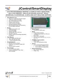
<strong>JControl</strong>/<strong>PLUI</strong><br />
JAVA PROGRAMMABLE POWER-LINE USER INTERFACE WITH<br />
BACKLIGHTED 128X64 PIXEL GRAPHIC LCD, JOYSTICK SWITCH, RTC,<br />
256K FLASH MEMORY, BUZZER, KONNEX PL132 COMPLIANT POWER-<br />
LINE-BCU, RS232-INTERFACE AND SOFT REALTIME SUPPORT<br />
� Virtual Machine Core<br />
� 8 Bit JAVA bytecode execution engine<br />
� 16 Bit processing word length<br />
� Max. 255 constant pool entries<br />
� 2.5k JAVA heap memory<br />
� 2 MIPS native core speed<br />
� Automatic garbage collection<br />
� Multi-threading support with extensions<br />
for soft realtime execution<br />
� Display<br />
� 128x64 pixel blue backlighted graphic<br />
LCD<br />
� FSTN technology<br />
� Viewing area: 46.0 x 23.0 mm<br />
� Dot pitch: 0.36 mm<br />
� Backlight and contrast adjustable by<br />
software<br />
� Joystick Switch<br />
� 5 switching positions<br />
� 4 directions (up, down, left, right) and<br />
center push<br />
� Flash Memory<br />
� 4 banks of 64k Flash<br />
� 256 byte sectors<br />
� > 10,000 erase/write cycles<br />
� Real-Time-Clock (RTC)<br />
� Philips PCF8563 type<br />
� 32.768kHz crystal oscillator<br />
� 0.25µA backup current @VCC=3.0V<br />
� Backup-power-supply by gold-cap<br />
� Power-Line-BCU<br />
� Konnex PL132 compliant power-line BCU,<br />
based on ST7537HS1<br />
� 2400bps, half duplex<br />
� output signal max. 116dB(µV)<br />
� receiving signal gain 70dB<br />
� Capacitive signal coupling to AC network<br />
� Separated switch-mode power-supply<br />
� Separate 8052-compliant microcontroller<br />
executes protocol stack<br />
� Internal FT1.2 protocol<br />
� Power-Supply<br />
� 230V AC power supply<br />
� Euro power cord for power supply and<br />
power-line communication<br />
� Buzzer (Piezo Ceramic)<br />
� Controlled by PWM output<br />
� Frequency range 250Hz..20kHz<br />
� RS232<br />
� 5-Wire RS232-Interface<br />
� 9-pin Sub-D-connector<br />
� 11 different baud rates from 300 up to<br />
250.000bps<br />
� None, even or odd parity<br />
� Automatic flow control by XON/XOFF or<br />
RTS/CTS<br />
� I/O-Pins (available internally)<br />
� 8-pin Molex micro connector<br />
� 6 Digital General-Purpose I/O Pins<br />
� 2 I/Os usable as PWM outputs<br />
� 4 I/Os usable as Analog inputs<br />
� Physical Dimensions<br />
� Size: 125x67x42mm (case w/o<br />
connectors)<br />
� Weight: 320g<br />
Version 1.3, October 2003
DIMENSIONS AND CONNECTORS<br />
Power-Line<br />
67mm<br />
Reset-Button<br />
DEVICE VARIANTS<br />
125mm<br />
128x64<br />
Graphic LCD<br />
Sales Type Native<br />
Core<br />
Speed<br />
PLAnalyzer<br />
Fig. 1: Dimensions and Connectors of the <strong>JControl</strong>/<strong>PLUI</strong><br />
Serial<br />
Baud Rates<br />
<strong>JControl</strong>/<strong>PLUI</strong><br />
Flash<br />
Organization<br />
<strong>JControl</strong>/<strong>PLUI</strong> 2 MIPS 300-250.000bps 256x256x4<br />
Table 1: Different Variants of the <strong>JControl</strong>/<strong>PLUI</strong><br />
Joystick-Button<br />
RS232<br />
© 2003 <strong>DOMOLOGIC</strong> <strong>Home</strong> <strong>Automation</strong> <strong>GmbH</strong> 2/19
<strong>JControl</strong>/<strong>PLUI</strong><br />
GENERAL DESCRIPTION<br />
The <strong>JControl</strong>/<strong>PLUI</strong> is a member of the <strong>JControl</strong><br />
device family, designed as free programmable<br />
Konnex PL132-compliant Power-Line-BCU (BCU<br />
stands for Bus Coupling Unit). The application<br />
software will be written in JAVA, compiled and<br />
executed by the JCVM8 8 Bit JAVA bytecode<br />
execution engine. The core runs with 2 MIPS<br />
native speed, providing 16 Bit processing word<br />
length, 2.5k JAVA heap memory, automatic<br />
garbage collection and multi-threading software<br />
execution. Applications in the fields of control,<br />
measurement and automation are supported by<br />
specific extensions for soft-realtime processing.<br />
Fig. 2 gives an overview of the <strong>JControl</strong>/<strong>PLUI</strong>. The<br />
upper part of the picture shows the <strong>JControl</strong><br />
System based on the JVCM8 with LCD, Joystick<br />
Switch, RTC, Flash Memory, Buzzer and RS232-<br />
Interface. The bottom part shows the Power-Line-<br />
BCU, combining an opto-galvanically separated<br />
interface, an 8052 microcontroller for the protocol<br />
stack, a ST7537HS1 power-line-modem, a<br />
capacitive power-line interface and a switch mode<br />
power-supply.<br />
The JCVM8 offers a set of built-in classes,<br />
providing fundamental support of the JAVA<br />
programming language and access to all local<br />
peripheral components like LCD, joystick switch,<br />
RTC, Flash memory, buzzer, communication ports<br />
(RS232 and Power-Line-BCU) and some internal<br />
universal I/O pins. Extended support is given by<br />
class libraries, linked automatically to the<br />
application by the <strong>JControl</strong>/DevelopmentSuite.<br />
This mechanism saves memory space, because<br />
exclusively the required classes are loaded to the<br />
system.<br />
Application programs are loaded via a serial<br />
communication interface to the Flash memory,<br />
organized into four banks of 64kByte. All banks<br />
POWER SUPPLY AND SYSTEM RESET<br />
The <strong>JControl</strong>/<strong>PLUI</strong> is powered by the mains<br />
(230V), using the supply line for both powering the<br />
<strong>JControl</strong> System and the Power-Line-BCU as well<br />
as for coupling the power-line signals into the<br />
network. The device operates with 5V DC<br />
internally. Under normal operating conditions, the<br />
power dissipation of the whole <strong>JControl</strong>/<strong>PLUI</strong> is<br />
below 1.4W.<br />
The device has no on/off switch and starts<br />
immediately by attaching the mains power. When<br />
the device is not powered, the internal RTC (Real<br />
Time Clock) is backed up by a gold cap.<br />
Gold<br />
Cap<br />
230V<br />
Power<br />
Supply<br />
3/19 © 2003 <strong>DOMOLOGIC</strong> <strong>Home</strong> <strong>Automation</strong> <strong>GmbH</strong><br />
+10V<br />
RTC<br />
I²C<br />
Buzzer<br />
+5V<br />
Switch-<br />
Mode<br />
Power-<br />
Supply<br />
Xtal<br />
32kHz<br />
+5V<br />
Reset<br />
POR<br />
4.20V<br />
+<br />
-<br />
LCD<br />
128x64<br />
/RESET<br />
Backlight<br />
<strong>JControl</strong>VM<br />
PWM #3<br />
(8bit)<br />
FLASH<br />
4 x 64k x 8<br />
Power-Line<br />
Interface<br />
PWM<br />
#2<br />
GPIO<br />
#8<br />
RS232Selector<br />
Power-Line<br />
Modem<br />
Power-Line-BCU<br />
Joystick Switch<br />
Switch<br />
1<br />
8052<br />
Microcontroller<br />
Fig. 2: <strong>JControl</strong>/<strong>PLUI</strong> Block Diagram<br />
RS232<br />
TTL<br />
GND<br />
may be used for application software or nonvolatile<br />
data.<br />
Various information about the specific <strong>JControl</strong><br />
device and its current state is available by<br />
accessing the system properties. In download<br />
mode, system properties may be read or written<br />
by remote using the <strong>JControl</strong> Download Protocol.<br />
Under normal operating conditions, the system<br />
properties can be accessed by application<br />
software using the methods getProperty and<br />
setProperty of the built-in class<br />
jcontrol.system.Management.<br />
To ensure a reliable start up phase, a power-on<br />
reset generator (POR) holds the reset signal of<br />
the VM and LCD while the output voltage of the<br />
internal <strong>JControl</strong> power supply is below 4.2V.<br />
After the initialization sequence of the JCVM8 has<br />
been executed, the application stored in the first<br />
Flash bank (bank 0) will be started (sole<br />
exception: see chapter Real Time Clock (RTC)).<br />
In the standard configuration of the <strong>JControl</strong>/<strong>PLUI</strong>,<br />
this is the application software (e.g. Power-Line<br />
Analyzer).<br />
0<br />
+5V<br />
GND<br />
+5V<br />
GND<br />
I/O<br />
PC
FLASH MEMORY ORGANIZATION<br />
The <strong>JControl</strong>/<strong>PLUI</strong> offers 4 banks of 64k Flash<br />
memory for application software or non-volatile<br />
data, numbered as bank 0 to bank 3 (Fig. 3). All<br />
banks are organized as 256 sectors by 256 bytes,<br />
numbered from sector 0 to sector 255. The Flash<br />
memory’s organization can be detected<br />
automatically by reading the system property<br />
flash.format. The returned string comprises<br />
the parameters xx (e.g. "256x256x4" for the<br />
<strong>JControl</strong>/<strong>PLUI</strong> device).<br />
64k x 8<br />
64k x 8<br />
64k x 8<br />
64k x 8<br />
One Flash bank can be selected for application<br />
software execution at a time. The current bank<br />
may be changed by restarting the JCVM8 using a<br />
different bank (see chapter Power Supply and<br />
System Reset). After system initialization, always<br />
the application software in bank 0 is executed.<br />
The Flash memory can be used to store nonvolatile<br />
data using the built-in class<br />
jcontrol.io.Flash. It provides methods to<br />
read and write complete sectors in any bank of<br />
the Flash memory.<br />
DOWNLOAD MODE<br />
Bank 3<br />
(User Application/Data)<br />
Bank 2<br />
(User Application/Data)<br />
Bank 1<br />
(User Application/Data)<br />
Bank 0<br />
(Boot Bank)<br />
Fig. 3: The two Flash Banks of <strong>JControl</strong>/<strong>PLUI</strong><br />
The system download mode is a fundamental<br />
functionality of the JCVM8, implemented in every<br />
<strong>JControl</strong> device. It is used for uploading and<br />
downloading application software or data from a<br />
host computer to the Flash memory, for auto<br />
identification of the <strong>JControl</strong> device and for<br />
reading or writing system properties by remote.<br />
The download mode is used e.g. by the<br />
development tools like JCManager and<br />
PropertyEdit.<br />
The system download mode may be entered by<br />
one of following four cases:<br />
<strong>JControl</strong>/<strong>PLUI</strong><br />
Fig. 4 gives an overview of bank 0’s internal<br />
structure: Application software is written upwards,<br />
starting at sector 0, and non-volatile data is stored<br />
downwards, starting at sector 254. This procedure<br />
reduces the possibility of resource conflicts<br />
between application and data. To offer a linear<br />
ascending number of sectors (starting at sector 0)<br />
to the application, the class<br />
jcontrol.io.Flash maps access to the logical<br />
sector 0 to the physical sector 254 of the Flash<br />
memory, access to logical sector 1 to the physical<br />
sector 253 and so on. The uppermost sector of<br />
bank 0 (sector 255) is used to store non-volatile<br />
system properties.<br />
Physical Sector<br />
Sector 255<br />
Sector 254<br />
Sector 253<br />
Sector 2<br />
Sector 1<br />
Sector 0<br />
Properties<br />
Nonvolatile<br />
Data<br />
Application<br />
Software<br />
Logical Sector<br />
Sector 0<br />
Sector 1<br />
Sector 2<br />
Sector 3<br />
Fig. 4: Internal Structure of Flash Bank 0<br />
For applications that makes use of the flash<br />
memory independently of its architecture, the<br />
external class jcontrol.storage.<br />
FlashStream is provided. It represents a<br />
memory cached data stream for reading and<br />
writing continuous data to or from the non-volatile<br />
flash memory.<br />
(1) Directly after the initialization sequence of the<br />
JCVM8: If no valid application software is<br />
available in bank 0 of the Flash memory, the<br />
device enters the system download mode.<br />
(2) During normal operating conditions: If the<br />
virtual machine is restarted by the method<br />
switchBank() of the built-in class<br />
jcontrol.system.Management and the<br />
new Flash bank contains no valid application<br />
software.<br />
(3) The system download mode may be enforced<br />
by pushing the joystick switch down while<br />
resetting the device as shown in Fig. 5.<br />
© 2003 <strong>DOMOLOGIC</strong> <strong>Home</strong> <strong>Automation</strong> <strong>GmbH</strong> 4/19
<strong>JControl</strong>/<strong>PLUI</strong><br />
(4) The mode may also be started by software<br />
calling the run()-Method of an instance of<br />
the built-in class<br />
jcontrol.system.Download.<br />
In the first three cases, a splash screen appears<br />
as shown in Fig. 6. The first line of the splash<br />
screen gives information about the <strong>JControl</strong><br />
device profile (“<strong>JControl</strong>/<strong>PLUI</strong>”). The second line<br />
shows the build date of the JCVM8, represented<br />
as format yyyymmddhhss (yyyy=year,<br />
mm=month, dd=day, hh=hour, ss=second). The<br />
following “+0100” in this example is optional and<br />
gives information about the time zone. The build<br />
date is also available as system property<br />
profile.date and used by the tools to select<br />
an appropriate device profile. The bottom line<br />
DISPLAY<br />
1 2<br />
Fig. 5: Entering the System Download Mode<br />
� Push the joystick switch down and hold it down, � push the<br />
reset button on the top of the <strong>JControl</strong>/<strong>PLUI</strong><br />
The <strong>JControl</strong>/<strong>PLUI</strong> comes with a 128x64 pixel<br />
monochrome graphic LCD in FSTN transflective<br />
technology, backlighted by a blue LED. The<br />
display has a viewing direction of 6 o’clock and is<br />
driven by a separate display controller (Samsung<br />
S6B1713), mounted as chip-on-glass circuit on<br />
the top side of the component. To obtain a high<br />
data bandwidth, the communication between<br />
JCVM8 and display is realized by an 8 bit parallel<br />
interface.<br />
The built-in class jcontrol.io.Display offers<br />
a set of methods for drawing pixels, lines,<br />
rectangles, circles, images, characters and strings<br />
on the display. It implements the interface<br />
jcontrol.io.Graphics for hardware<br />
abstraction. Images are supported using the pixelbased<br />
<strong>JControl</strong> Image File format (JCIF, revision<br />
0001); fonts have to be formatted using the pixelbased<br />
<strong>JControl</strong> Font Definition format (JCFD,<br />
revision 0002). The class<br />
jcontrol.io.Display includes a proportional<br />
system font (8 pixel font height) by default.<br />
For detecting the display dimensions<br />
automatically, the system property<br />
display.dimensions returns a string<br />
5/19 © 2003 <strong>DOMOLOGIC</strong> <strong>Home</strong> <strong>Automation</strong> <strong>GmbH</strong><br />
Fig. 6: Splash screen of the system download mode<br />
shows the parameters of the RS232 interface,<br />
fixed to 19200 bps, 8 data bits, no parity and 1<br />
stop bit.<br />
Using the Download Mode by Applications<br />
The built-in class jcontrol.system.Download<br />
may be used to access or extend the download<br />
functionality by application software, e.g. to<br />
implement comfortable download or upload<br />
features for specific applications.<br />
When the system download mode is started by<br />
software (see case 4), no splash screen appears<br />
and the baud rate is not fixed to 19200bps, but set<br />
to the value held by the system property<br />
rs232.baudrate (default: 19200bps). If data is<br />
written to the flash memory, the download mode<br />
will perform a system reset when it is quitted.<br />
Otherwise it returns to the calling application. See<br />
API documentation for more information about this<br />
class.<br />
comprising the parameters<br />
xx,<br />
specified by "128x64x1" for the <strong>JControl</strong>/<strong>PLUI</strong><br />
device. The coordinates of the display are<br />
organized from left to right and from top to bottom<br />
counting from 0 to size-1, see also Fig. 7.<br />
The display contrast may be adjusted by software<br />
using the system property display.contrast.<br />
The value is saved to Flash memory, assuring<br />
that it will be restored by the system during powerup.<br />
The blue backlight LED of the display is<br />
controlled directly by the reserved PWM channel<br />
#2 of the JCVM8. For improved hardware<br />
- x<br />
0<br />
+ 127<br />
0<br />
-<br />
y<br />
+<br />
63<br />
128x64<br />
Pixels<br />
Fig. 7: Coordinates used by the LCD-class
abstraction, the external class<br />
jcontrol.io.Backlight is provided, enabling<br />
JOYSTICK SWITCH<br />
The joystick switch enables compound actions by<br />
a single knob. It features five degrees of freedom,<br />
controlled by lever and push operations.<br />
The built-in class jcontrol.io.Keyboard<br />
provides methods to read the switch on character<br />
basis, including raw access, buffered access,<br />
automatic repetition and acoustic feedback.<br />
Fig. 8 gives an overview of the moving directions<br />
of the joystick switch. The letters ‘S’, ‘U’, ‘L’, ‘D’<br />
and ‘R’ are returned by the method read() of the<br />
class jcontrol.io.Keyboard when the switch<br />
REAL TIME CLOCK (RTC)<br />
The real time clock (RTC) of the <strong>JControl</strong>/<strong>PLUI</strong> is<br />
realized by a separate component, connected<br />
internally by the I²C bus to the JCVM8. During<br />
power-off state, the RTC is supplied by a backup<br />
gold cap, keeping the time information up-to-date.<br />
The RTC provides year, month, day, weekday,<br />
hours, minutes and seconds. Besides the current<br />
time, an alarm time is supported by hardware. The<br />
alarm flag may be polled by software.<br />
The built-in class jcontrol.system.RTC<br />
implements methods for reading and writing the<br />
current time and alarm time. A time information is<br />
BUZZER<br />
A piezo buzzer (mounted inside of the device) is<br />
used to generate acoustic signals. The system<br />
uses the buzzer for acoustic feedback of switch<br />
events and for signalling system exceptions. Both<br />
features may be enabled or disabled by the<br />
system properties buzzer.systembeep and<br />
buzzer.keyboardbeep. Additionally, an<br />
application software may control the buzzer using<br />
the external class jcontrol.io.Buzzer,<br />
implementing the interface<br />
jcontrol.io.SoundDevice for hardware<br />
abstraction. This class provides methods to<br />
activate the buzzer using a specified frequency<br />
(250...32767Hz) for a specified duration (in ms).<br />
RS232 COMMUNICATION<br />
The <strong>JControl</strong>/<strong>PLUI</strong> provides one asynchronous<br />
serial communication interface, connected by a<br />
multiplexer switch to two different communication<br />
channels. The first communication channel<br />
<strong>JControl</strong>/<strong>PLUI</strong><br />
to set the backlight in 256 steps from 0 (off) to 255<br />
(max brightness).<br />
is moved to one of these positions. The letters are<br />
defined by the default keyboard map, that may be<br />
changed by an application program for software<br />
compatibility reasons.<br />
S<br />
R<br />
Fig. 8: Moving Directions of the Multifunction Switch<br />
represented by an instance of the built-in class<br />
jcontrol.system.Time, combining the fields<br />
year, month, day, weekday, hours, minutes and<br />
seconds.<br />
The RTC is based on the Philips PCF8563<br />
integrated circuit, clocked by a separate 32.768<br />
kHz quartz crystal. It operates on a supply voltage<br />
down to 1.0 V and consumes approx. 250µA<br />
@VDD=3.0V (Tamb=25°C). The RTC allocates the<br />
I²C-bus slave addresses A3h (for reading) and<br />
A2h (for writing). It may be accessed directly<br />
using the built-in class jcontrol.comm.I2C.<br />
The system property buzzer.enable is provided<br />
to enable or disable the buzzer when it is used by<br />
an application.<br />
Furthermore, the external class<br />
jcontrol.toolkit. iMelody is provided,<br />
playing complete melodies given by the iMelody-<br />
Format (IMY, published by the Infrared Data<br />
Association, IrDA).<br />
The buzzer used inside the <strong>JControl</strong>/<strong>PLUI</strong> is<br />
controlled by the reserved PWM channel #3 and<br />
has a specified frequency range from 250Hz to<br />
20kHz.<br />
(named EXTERNAL) is used to communicate with<br />
a PC, the other (named INTERNAL) is used to<br />
communicate with the integrated Power-Line-<br />
BCU. The switch is controlled by the reserved<br />
© 2003 <strong>DOMOLOGIC</strong> <strong>Home</strong> <strong>Automation</strong> <strong>GmbH</strong> 6/19<br />
L<br />
U<br />
D
<strong>JControl</strong>/<strong>PLUI</strong><br />
GPIO pin #8 of the JCVM8. For improved<br />
hardware abstraction, the external class<br />
jcontrol.comm.RS232Selector is provided<br />
to control the switch by its method selectPort.<br />
The parameter for this method may be either the<br />
static integer EXTERNAL for the Sub-D<br />
connector or INTERNAL for the Power-Line-BCU.<br />
Fig. 9 shows how the two communication<br />
channels are connected to the asynchronous<br />
serial interface of the JCVM8.<br />
JCVM8<br />
RS232Selector<br />
Fig. 9: Wiring of the two Communication Channels<br />
By default (e.g. during system reset), the switch<br />
enables the communication via the RS232<br />
interface, available as 9-pin female sub-D<br />
connector on the right edge of the device. This<br />
channel is used to upload and download<br />
application software or data from or to the flash<br />
memory, for auto identification of the <strong>JControl</strong><br />
device and for reading or writing system<br />
properties by remote. The pin assignment of the<br />
9-pin Sub-D connector is shown in Fig. 10. A<br />
simple 1:1 extension cable may be used to<br />
connect the <strong>JControl</strong>/<strong>PLUI</strong> to a PC.<br />
7<br />
Switch<br />
1<br />
0<br />
2 3<br />
8<br />
5<br />
EXTERNAL<br />
INTERNAL<br />
RS232<br />
Pin<br />
TTL +5V<br />
Fig. 10: Pin Assignment of the RS232 Connector<br />
(9-pin female sub-D connector)<br />
The second communication port is wired internally<br />
and will be used for Power-Line Communication. It<br />
is connected via an opto-galvanically separated<br />
interface to the Power-Line-BCU. Refer to chapter<br />
Power-Line Communication (page 8 ff.) to obtain<br />
more information about this topic.<br />
2<br />
3<br />
5<br />
7<br />
8<br />
Signal<br />
TxD<br />
RxD<br />
GND<br />
CTS<br />
RTS<br />
7/19 © 2003 <strong>DOMOLOGIC</strong> <strong>Home</strong> <strong>Automation</strong> <strong>GmbH</strong><br />
GND<br />
GND<br />
9-pin Sub-D<br />
Connector<br />
Power-Line<br />
Modem<br />
The built-in class jcontrol.comm.RS232<br />
provides methods for reading, writing and<br />
configuring the RS232 interface. It supports<br />
buffered read access and operates on byte,<br />
char, string and utf8 basis. Automatic<br />
echoing is also supported by the readLine()<br />
method.<br />
The RS232 communication interface supports 11<br />
different baud rates, starting from 300 up to<br />
250.000bps. The baud rate is changed using the<br />
method setBaudrate() of the built-in class<br />
jcontrol.comm.RS232 (see Table 2 for a list of<br />
all valid settings). When an application attempts to<br />
set an unsupported baud rate, always the fallback<br />
setting 19200bps is used. When no baud<br />
rate value is set by the application, the default<br />
value specified by the system property<br />
rs232.baudrate is used.<br />
Baud Rate Parameter for<br />
setBaudrate<br />
Comment<br />
300 300<br />
600 600<br />
1200 1200<br />
2400 2400<br />
4800 4800<br />
9600 9600<br />
19.200 19200 Fall-back setting<br />
31.250 31250 MIDI<br />
62.500 62<br />
125.000 125<br />
250.000 250<br />
Table 2: Supported Baud Rates<br />
Additionally, the RS232 communication interface<br />
supports a parity bit (9 th data bit) as well as flow<br />
control (by XON/XOFF or RTS/CTS). All options<br />
are defined by the current communication<br />
MSB<br />
64 32<br />
16<br />
f f<br />
8<br />
e<br />
4<br />
2<br />
1<br />
pp<br />
LSB<br />
Parity<br />
00 = No Parity ( N)<br />
01 = Even Parity ( E)<br />
10 = Odd Parity ( O)<br />
11 = Reserved<br />
Echo<br />
0 = Echo disabled<br />
1 = Echo enabled<br />
Flow Control<br />
00 = None<br />
01 = XON/XOFF<br />
10 = RTS/CTS<br />
11 = Reserved<br />
Fig. 11: RS232 Communication Parameters
parameters, configured using method<br />
setParams() of the built-in class<br />
jcontrol.comm.RS232. As shown in Fig. 11,<br />
the options are combined to a single bitmask.<br />
Appropriate constant field values are defined by<br />
the class jcontrol.comm.RS232. When the<br />
parameters are not changed by the application<br />
software, always the default settings specified by<br />
the system property rs232.params are used.<br />
The following parity modes are supported: “8N1”<br />
(8 data bits, no parity, 1 stop bit), “8E1” (8 data<br />
POWER-LINE COMMUNICATION<br />
230V<br />
Switch-<br />
Mode<br />
Power-<br />
Supply<br />
+10V<br />
Power-Line<br />
Interface<br />
The <strong>JControl</strong>/<strong>PLUI</strong> is equipped with an integrated<br />
Konnex PL132-compliant Power-Line-BCU with a<br />
separate 8052-CPU, performing the physical layer<br />
and data link layer of the protocol stack. This<br />
reduces the software complexity and performance<br />
overhead of the <strong>JControl</strong> application software.<br />
The BCU is connected via an opto-galvanically<br />
separated 5-wire serial interface to the JCVM8<br />
(see block diagram Fig. 12). Note that the<br />
multiplexer switch has to be configured to<br />
INTERNAL communication for establishing the link<br />
between the JCVM8 and the Power-Line-BCU<br />
(see also chapter RS232 Communication, page 6<br />
ff.). The communication protocol is based on the<br />
FT1.2 specification to ensure a reliable data<br />
transfer (refer to EN60870 or IEC870). Only the<br />
signals TxD and RxD are used, RTS and CTS are<br />
reserved for future use. The communication<br />
parameters are fixed to 19200bps, 8 data bits,<br />
even parity and 1 stop bit. The external class<br />
jcontrol.comm.FT1_2 provides a set of FT1.2based<br />
communication methods for sending and<br />
Preamble<br />
16 Bits<br />
Domain<br />
Address<br />
2 Bytes<br />
+5V<br />
Control<br />
Field<br />
1 Byte<br />
16 Bits<br />
Power-Line<br />
Modem<br />
<strong>JControl</strong>/<strong>PLUI</strong><br />
bits, even parity, 1 stop bit) and “8O1” (8 data bits,<br />
odd parity, 1 stop bit). For flow control, two<br />
different modes are supported: Software flow<br />
control (by XON/XOFF) and hardware flow control<br />
(by RTS/CTS). Software flow control uses the<br />
ASCII-codes XON (0x11) and XOFF (0x13).<br />
Hardware flow control is realized by the external<br />
signals RTS (pin 8) and CTS (pin 7) of the female<br />
sub-D connector.<br />
8052<br />
Microcontroller<br />
Fig. 13: Block diagram of the Power-Line-Modem<br />
8 Bits<br />
Source<br />
Address<br />
6 Bits<br />
8 Bits<br />
6 Bits<br />
NPCI<br />
Field<br />
2 Bytes 2 Bytes 1 Byte 1 Byte 1 Byte<br />
0-n Bytes<br />
with Forward Error Correction (FEC)<br />
TxD<br />
RxD<br />
RTS<br />
CTS<br />
JCVM8<br />
receiving power-line messages and for configuring<br />
the BCU.<br />
The Power-Line BCU supports six different types<br />
of messages, each preceded by a specific service<br />
code (mcode, see Table 3). For sending and<br />
receiving power-line messages on link layer basis,<br />
the L_DATA-frames are provided (request,<br />
indication and confirm). The remaining messages<br />
(PC_SET_VAL and PC_GET_VAL) are used to<br />
configure the BCU, e.g. to specify the number of<br />
send retries.<br />
Name mcode Direction<br />
L_DATA_req 0x11 JCVM8→BCU<br />
L_DATA_con 0x4E BCU→JCVM8<br />
L_DATA_ind 0x49 BCU→JCVM8<br />
PC_SET_VAL_req 0x46 JCVM8→BCU<br />
PC_GET_VAL_req 0x4C JCVM8→BCU<br />
PC_GET_VAL_con 0x4B BCU→JCVM8<br />
Table 3: Messages supported by the Power-Line BCU<br />
Header Data FEC Data FEC Data FEC Data FEC Data FEC<br />
FEC<br />
Destination<br />
Address<br />
8 Bits 6 Bits 8 Bits 6 Bits 8 Bits 6 Bits<br />
6 Bits<br />
TPCI<br />
Field<br />
APCI<br />
Field<br />
2 Bytes<br />
© 2003 <strong>DOMOLOGIC</strong> <strong>Home</strong> <strong>Automation</strong> <strong>GmbH</strong> 8/19<br />
Data<br />
Fig. 12: Frames modulated to the Power-Line Network<br />
Frame Check<br />
Sequence
<strong>JControl</strong>/<strong>PLUI</strong><br />
In general, the L_DATA-messages exchanged<br />
between the <strong>JControl</strong> application and the BCU<br />
differ from those messages modulated to the<br />
power-line network (see also Fig. 13): Some data<br />
fields (preamble, header, domain address and<br />
frame check sequence) are inserted automatically<br />
L_DATA_req<br />
Service Control<br />
Field<br />
Source<br />
Address<br />
Destination<br />
Address<br />
NPCI<br />
Field<br />
9/19 © 2003 <strong>DOMOLOGIC</strong> <strong>Home</strong> <strong>Automation</strong> <strong>GmbH</strong><br />
by the Power-Line-BCU; therefore the <strong>JControl</strong><br />
application has to handle the fields source<br />
address, control field, destination address, NPCI,<br />
TPCI and data only. In the following, the<br />
messages will be explained in separate<br />
subchapters.<br />
TPCI<br />
Field<br />
Data<br />
(APCI)<br />
Data Data<br />
0x11 cc 0x00 0x00 high low nn tt byte 1 byte 2 byte n<br />
The message L_DATA_req (req = request) is<br />
used to send data to other power-line devices in<br />
the network. The service code is 0x11, followed<br />
by a control field (see also Fig. 14). The source<br />
address (here: 0x0000) will be replaced by the<br />
individual address of the Power-Line BCU when<br />
sending (the individual address may be configured<br />
using the control message PC_SET_VAL.req).<br />
The 16-bit destination address is the individual<br />
address or group address of the receiver, the<br />
fields NPCI (see also Fig. 15) and TPCI specify<br />
network- and transport layer information. The<br />
following data fields are used to transfer up to 15<br />
bytes of APCI- and APDU information.<br />
The L_DATA_req message is replied by a<br />
L_DATA_con message.<br />
L_DATA_con<br />
Service Control<br />
Field<br />
Source<br />
Address<br />
Destination<br />
Address<br />
NPCI<br />
Field<br />
TPCI<br />
Field<br />
Data<br />
(APCI)<br />
Data<br />
(APDU)<br />
Data<br />
(APDU)<br />
0x4E cc high low high low nn tt byte 1 byte 2 byte n<br />
The message L_DATA_con (con = confirm) is<br />
sended by the BCU as confirmation of a<br />
L_DATA_req message (positive or negative<br />
confirmation). The service code is 0x4E; most of<br />
the following fields return the same values as<br />
given by the initiating L_DATA_req message. The<br />
control field (Fig. 16) returns a confirm flag (Bit 0),<br />
signalling if the process was successful or not,<br />
and a repeat bit (Bit 5) (set to ‘1’ if the message<br />
was repeated at least one times). Additionally, the<br />
individual address of the BCU is inserted in the<br />
source address field. The NPCI field is the same<br />
as shown for the L_DATA_req message (Fig. 15).<br />
MSB<br />
Fig. 14: Control Field (cc) of L_Data_req message<br />
MSB<br />
MSB<br />
0 0 0 0 p p a 0<br />
h i i i j j j j<br />
Fig. 15: NPCI (nn) Field of L_Data_req message<br />
1 0 r 1 p p 0 c<br />
LSB<br />
LSB<br />
LSB<br />
Acknowledge request<br />
1 = no L2 Ack request<br />
Priority<br />
00 = lowest priority<br />
11 = highest priority<br />
Data Length Count (0..15)<br />
Hop Count (0..7)<br />
Address Type<br />
0 = Individual Address<br />
1 = Group Address<br />
Confirm<br />
1 = Error<br />
Priority<br />
00 = lowest priority<br />
11 = highest priority<br />
Repeat<br />
0 = No Repeat<br />
1 = Message repeatet<br />
Fig. 16: Control Field (cc) of L_Data_con message
L_DATA_ind<br />
Service Control<br />
Field<br />
Source<br />
Address<br />
Destination<br />
Address<br />
NPCI<br />
Field<br />
TPCI<br />
Field<br />
Data<br />
(APCI)<br />
Data<br />
(APDU)<br />
<strong>JControl</strong>/<strong>PLUI</strong><br />
Data<br />
(APDU)<br />
0x49 cc high low high low nn tt byte 1 byte 2 byte n<br />
The L_DATA_ind message (ind = indication) is<br />
sent by the BCU when a power-line-message was<br />
received. The service code is 0x49, followed by<br />
data fields similar to the fields described for the<br />
L_DATA_req message. Except the control field<br />
differs (Fig. 17): The repeat flag (Bit 5) indicates if<br />
the message was repeated at least one times.<br />
Note: A message will only be received by the BCU<br />
when the address filters (Individual Address) are<br />
set properly.<br />
PC_SET_VAL_req<br />
Service Number<br />
Bytes<br />
Memory<br />
Address<br />
Data Data Data<br />
0x46 nn high low byte 1 byte 2 byte n<br />
The PC_SET_VAL_req message (req = request)<br />
is used to write various configuration parameters<br />
to the Power-Line BCU. Each parameter has the<br />
size of one byte. The service code is 0x46,<br />
followed by the number of bytes to write and the<br />
starting memory address (0x0000 to 0x0006,<br />
see Table 4). The following data string will be<br />
written consecutive to the memory starting at the<br />
specified address.<br />
PC_GET_VAL_req<br />
Service Number<br />
Bytes<br />
Memory<br />
Address<br />
0x4C nn high low<br />
The PC_GET_VAL_req message (req = request)<br />
is used to read configuration parameters from the<br />
Power-Line BCU. The service code is 0x4C,<br />
followed by the number of bytes to read and the<br />
starting memory address. The BCU replies with a<br />
PC_GET_VAL_ind message.<br />
MSB<br />
1 0 r 1 p p 0<br />
Memory<br />
Address<br />
Description Default<br />
Value<br />
0x0000 Domain Address Low 0x00<br />
0x0001 Domain Address High 0x00<br />
0x0002 Individual Address Low 0x00<br />
0x0003 Individual Address High 0x00<br />
0x0004 Number<br />
NACK<br />
of Retries when 0x02<br />
0x0005 Number of Retries when 0x02<br />
BUSY<br />
0 LSB<br />
Priority<br />
00 = lowest priority<br />
11 = highest priority<br />
Repeat<br />
0 = No Repeat<br />
1 = Message repeatet<br />
Fig. 17: NPCI (nn) Field of L_Data_req message<br />
0x0006 Number of Repeats when No<br />
Acknowledge<br />
Table 4: Memory Addresses of BCU Configuration<br />
Parameters<br />
© 2003 <strong>DOMOLOGIC</strong> <strong>Home</strong> <strong>Automation</strong> <strong>GmbH</strong> 10/19<br />
0x02
<strong>JControl</strong>/<strong>PLUI</strong><br />
PC_GET_VAL_ind<br />
Service Number<br />
Bytes<br />
Memory<br />
Address<br />
Data Data Data<br />
0x4B nn high low byte 1 byte 2 byte n<br />
The PC_GET_VAL_ind message returns the<br />
configuration parameters of the Power-Line BCU,<br />
requested by a PC_GET_VAL_req message. The<br />
EXTENSION PORT<br />
For system extensions, an 8-pin extension port<br />
connector is available inside the device. It<br />
provides the internal operating voltage (+5V),<br />
GND and six universal I/O-pins.<br />
Fig. 18 gives an overview of the extension port<br />
(Molex micro connector type 53398-0890). The<br />
connector is placed at the top PCB (inside the<br />
upper half of the case). For adaptation, use a<br />
Molex 51021-0800 female crimp connector.<br />
Pin Vcc (1) provides the internal operating voltage<br />
of +5V in reference to GND (8). Vcc may be used<br />
to supply external hardware with 5V, generated by<br />
a linear regulator of <strong>JControl</strong>/<strong>PLUI</strong>. Universal I/O<br />
signals are available at pin 2 to pin 7 of the<br />
extension port.<br />
I/O PINS (GPIO, PWM, ADC)<br />
Six I/O pins are available for system extensions at<br />
the extension port connector, numbered from pin<br />
2 to pin 7. Each pin may be used as digital input<br />
or output (General Purpose I/O, GPIO). The builtin<br />
class jcontrol.io.GPIO is provided to<br />
control the digital I/Os, numbered as GPIO #0 to<br />
GPIO #5. Four different configuration modes are<br />
supported:<br />
� FLOATING: Standard digital input<br />
� PULLUP: Digital input with integrated pull up<br />
resistor (60-240kΩ)<br />
� PUSHPULL: Standard digital output<br />
� OPENDRAIN: Digital output, set to highimpedance<br />
state when HIGH<br />
Two of the ten GPIO pins are also connected to<br />
an integrated Pulse Width Modulator (PWM) with<br />
a resolution of up to 8 bits. This feature is<br />
controlled by the built-in class<br />
11/19 © 2003 <strong>DOMOLOGIC</strong> <strong>Home</strong> <strong>Automation</strong> <strong>GmbH</strong><br />
service code is 0x4B, followed by the number of<br />
bytes, the starting memory address and a<br />
consecutive string of data.<br />
8 1<br />
Mounting Hole<br />
PIN Function<br />
1<br />
2<br />
V CC (5V)<br />
GPIO #0 / PWM #0<br />
3 GPIO #1 / PWM #1<br />
4 GPIO #2 / ADC #0<br />
5 GPIO #3 / ADC #1<br />
6 GPIO #4 / ADC #2<br />
7 GPIO #5 / ADC #3<br />
8 GND<br />
Connector Type:<br />
PCB: Molex 53398-0890<br />
Crimp: Molex 51021-0800<br />
Fig. 18: Extension Port of the <strong>JControl</strong>/<strong>PLUI</strong><br />
jcontrol.io.PWM. The generated signals are<br />
available via the PWM channels 0 and 1. The<br />
device uses a single frequency generator for all<br />
channels, hence the frequency of the channels<br />
has to be the same. Please note that every pin<br />
configured as PWM output is not available as<br />
GPIO.<br />
The remaining four pins are connected to the<br />
internal 8-bit A/D converter and may be used as<br />
analog inputs. The built-in class<br />
jcontrol.io.ADC is provided to control this<br />
feature. When a pin is used as analog input, it<br />
should be configured to FLOATING mode using<br />
the class jcontrol.io.GPIO.<br />
The following table gives an overview on the<br />
features of each pin.
Extension<br />
Port<br />
Pin<br />
Channel<br />
#<br />
Floating<br />
Input<br />
GPIO PWM ADC<br />
Input<br />
With<br />
Pullup<br />
Push<br />
Pull<br />
Output<br />
Open<br />
Drain<br />
Output<br />
Channel<br />
#<br />
<strong>JControl</strong>/<strong>PLUI</strong><br />
Channel<br />
#<br />
2 0 � � � � 0 -<br />
3 1 � � � � 1 -<br />
4 2 � � � � - 0<br />
5 3 � � � � - 1<br />
6 4 � � � � - 2<br />
7 5 � � � � - 3<br />
Table 5: Features of pins of the extension port<br />
© 2003 <strong>DOMOLOGIC</strong> <strong>Home</strong> <strong>Automation</strong> <strong>GmbH</strong> 12/19
<strong>JControl</strong>/<strong>PLUI</strong><br />
I²C/SMBUS COMMUNICATION<br />
A separate I²C communication interface is used<br />
internally to communicate with the RTC PCF8563,<br />
allocating the addresses A3h for reading and A2h<br />
for writing.<br />
The I 2 C bus is a de facto standard for on-board<br />
inter integrated circuit communication. It was<br />
developed by Philips Semiconductors in the early<br />
1980's. Many integrated circuits supporting the I²C<br />
bus. SMBus is a kind of extended I²C bus,<br />
developed by Intel in 1995 as System<br />
Management Bus. It is used e.g. in personal<br />
computers and servers for low-speed system<br />
management communications. Mostly, the SMBus<br />
JCVM8 RESTRICTIONS<br />
Not all JAVA features are implemented by the<br />
JCVM8. The following list gives an overview on<br />
the restrictions:<br />
� Data type int is limited to 16 bit processing<br />
word length (not 32 bit)<br />
� Data types long, float and double are not<br />
implemented. When used, one of the following<br />
two error codes is generated (context<br />
dependent):<br />
� BytecodeNotSupportedError (6)<br />
� UnsupportedArrayTypeError (9)<br />
� The number of constants in the constant pool<br />
is limited to 255 (will be checked by the<br />
JCManager before upload)<br />
ERROR CODES<br />
When an exception is thrown and not handled by<br />
the application, the JCVM8 generates an error<br />
code. Some of the errors (listed in the following<br />
Table 6) are specific to the JCVM8 and not<br />
common in the JAVA programming language<br />
(labeled with 1 ). Other error codes are masked<br />
exceptions, because they are generated instead<br />
of an exception (labeled with 2 ).<br />
Every error restarts the JCVM8 in error condition.<br />
Afterwards the method onError() of the built-in<br />
13/19 © 2003 <strong>DOMOLOGIC</strong> <strong>Home</strong> <strong>Automation</strong> <strong>GmbH</strong><br />
is used to interconnect the sensors for<br />
temperatures, voltages, rotation speed of fans etc.<br />
The built-in class jcontrol.comm.I2C provides<br />
methods for using the <strong>JControl</strong> device as bus<br />
master. It supports 7 bit and 10 bit addressing<br />
schemes as well as reading and writing single<br />
chars or byte streams. It implements a simple<br />
hardware layer, therefore any bus error and any<br />
arbitration lost results in an IOException after<br />
some retries. To avoid blocking, the class<br />
implements contrary to the I²C specification a bus<br />
timeout.<br />
� Cast check for primitive arrays is not<br />
supported and causes an error<br />
(NotImplementedError)<br />
� It is not possible to call object methods on<br />
primitive arrays, e.g.<br />
new int[25].equals(myObject)<br />
� Some exceptions can not be catched by an<br />
application, because they generate an error<br />
code. When thrown, the JCVM8 is restarted in<br />
error condition and the error handler is called<br />
(see also chapter Error Codes).<br />
� Implementation of classes in the package<br />
java.lang is incomplete (see <strong>JControl</strong><br />
JAVADOC)<br />
class jcontrol.system.ErrorHandler is<br />
invoked. More details about the error state is<br />
passed by parameters to the onError() method.<br />
The built-in error handler may be overwritten by a<br />
user-defined error handler stored in Flash bank 0.<br />
See the error handler included in the<br />
SystemSetup software for demonstration.<br />
Following table gives an overview on the error<br />
codes generated by the JCVM8.<br />
ID Name Description<br />
1 HandleError 1)<br />
Internal VM error<br />
2 NullPointerException 2)<br />
Attempt to use NULL where an object is required.<br />
3 OutOfMemoryError Generated when no memory is available<br />
4 BytecodeNotAvailableError 1)<br />
Attempt to execute an invalid bytecode
<strong>JControl</strong>/<strong>PLUI</strong><br />
ID Name Description<br />
5 BytecodeNotSupportedError 1)<br />
Attempt to execute an unsupported bytecode, e.g.<br />
bytecodes for 64-bit arithmetic or floating point<br />
processing<br />
6 BytecodeNotDefinedError 1)<br />
Attempt to execute an undefined bytecode<br />
7 ArithmeticException 2)<br />
Exception during arithmetic processing, e.g. division<br />
by zero<br />
8 NegativeArraySizeException 2)<br />
Attempt to create an array with negative size<br />
9 UnsupportedArrayTypeError 1)<br />
Arrays of this type are not supported<br />
10 ArrayIndexOutOfBoundsException 2)<br />
Array index is out of bounds<br />
11 ClassCastException 2)<br />
Attempt to cast an object which is not of an<br />
appropriate runtime type.<br />
12 NoCodeError 1)<br />
Thrown when a method is called that implements no<br />
code<br />
13 WaitForMonitorSignal 1)<br />
Used internally by the VM<br />
14 ExternalNativeError 1)<br />
Generated when a native method is called that is not<br />
stored in ROM<br />
15 FatalStackFrameOverflowError 1)<br />
Generated when the stack size is not sufficent<br />
16 InstantiationException 2)<br />
Attempt to instantiate an abstract class or interface<br />
17 IllegalMonitorStateException 2)<br />
E.g. when a wait is called without an appropriate<br />
monitor<br />
18 UnsatisfiedPrelinkError 1)<br />
Error due to a failed prelinking process<br />
19 ClassFormatError 1)<br />
Generated when a failed while class loading<br />
20 ClassTooBigError 1)<br />
The size of a class exceeds the limitations<br />
21 PreLinkError 1)<br />
Error due to a failed prelinking process<br />
22 PreLinkedUnresolvedError 1)<br />
Error due to a failed prelinking process<br />
23 UnsupportedConstantTypeError 1)<br />
Generated when the type of a constant is not<br />
supported by the JCVM8 (long, float or double)<br />
24 MalformatedDescriptorError 1)<br />
Error while dereferencing constant pool, e.g. due to<br />
wrong class file format<br />
25 RuntimeRefTableOverrunError 1)<br />
More class references used than specified in a class<br />
file<br />
26 NoSuchFieldError Referenced field not found<br />
27 IllegalAccessError Tried to access a field or method from wrong scope<br />
(e.g. private)<br />
28 NoSuchMethodError Could not find referenced method<br />
29 TooMuchParametersError 1)<br />
A method uses more parameters than supported by<br />
the JCVM8 (max. 16)<br />
30 ThrowFinalError 1)<br />
Uncatched user defined exception. Exception name<br />
is passed to the onError() method.<br />
31 NoClassDefFoundError 1)<br />
Unable to find a class by name<br />
32 IndexOutOfBoundsException 2)<br />
Thrown by some methods using String or array<br />
parameters and indices that are out of bounds<br />
33 ArrayDimensionError 1)<br />
Generated when an array is created with more than<br />
2 dimensions (only 1 or 2 dimensions supported)<br />
34 DeadlockError 1)<br />
Generated by the JCVM8 scheduler when two or<br />
more threads inheriting from each other<br />
35 IncompatibleClassChangeError Generated when an interface is invoked for an<br />
object, that is not implementing the interface<br />
36 NotImplementedError 1)<br />
Generated when an unimplemented JAVA feature is<br />
used<br />
Table 6: Error Codes generated by the JCVM8<br />
1) Error codes generated exclusively by the JCVM8. Not common in the JAVA programming language.<br />
2)<br />
JCVM8 error codes generated by the JCVM8 instead of exceptions. Can not be handled by an exception handler. May be replaced by<br />
JAVA exceptions in future revisions of the JCVM8.<br />
© 2003 <strong>DOMOLOGIC</strong> <strong>Home</strong> <strong>Automation</strong> <strong>GmbH</strong> 14/19
<strong>JControl</strong>/<strong>PLUI</strong><br />
SYSTEM PROPERTIES<br />
System properties providing specific information<br />
about the <strong>JControl</strong> device. All properties are<br />
identified by a fixed string (the content is always<br />
formatted as string). The properties may be read<br />
or written using the methods getProperty()<br />
and setProperty() of the built-in class<br />
jcontrol.system.Management. In download<br />
mode, the tool PropertyEdit may be used to read<br />
or write the properties by remote.<br />
15/19 © 2003 <strong>DOMOLOGIC</strong> <strong>Home</strong> <strong>Automation</strong> <strong>GmbH</strong><br />
The system properties are categorized into ROM<br />
properties and non-volatile properties. ROM<br />
properties are stored in read-only memory of the<br />
device and can not be changed. Non-volatile<br />
properties are held in the upper sector of Flash<br />
bank 0 and may be changed by software.<br />
Key Type Value Description<br />
profile.name String <strong>JControl</strong>/<strong>PLUI</strong> <strong>JControl</strong> Profile Name<br />
profile.date String yyyymmddhhmm Date of JCVM build<br />
system.heapsize Int 2688 Size of internal JAVA heap memory<br />
flash.format String “256x256x4” Flash Organization<br />
(bytes x blocks x banks)<br />
io.gpiochannels Int 6 Number of GPIO channels<br />
io.pwmchannels Int 2 Number of PWM channels<br />
io.adcchannels Int 4 Number of ADC channels<br />
display.dimensions String “128x64x1” Display dimensions<br />
(width x height x colour_depth)<br />
Table 7: ROM Properties (saved in ROM, read access only)<br />
Key Type Range Default Description<br />
system.standbytimer Int 0..32767 60 Auto-standby time (in seconds)<br />
system.userbank Int 0..3 0 Flash bank used for user application<br />
rtc.poweronbank Int 0..3 0 Bank selected to start application after<br />
power on initiated by RTC alarm<br />
buzzer.enable Bool true, false true Enable or disable buzzer to be used by<br />
application software<br />
buzzer.systembeep Bool true, false true Enable or disable system sound<br />
(set independent from buzzer.enable)<br />
buzzer.keyboardbeep Bool true, false true Enable or disable keyboard beep<br />
(set independent from buzzer.enable)<br />
display.contrast Int 0..255 40 LCD contrast adjustment<br />
rs232.params Int 0, 1, 8, 9 0 Bitmask holding RS232 configuration<br />
� Bit 1:0 00 = No Parity<br />
01 = PARITY_EVEN enabled<br />
10 = PARITY_ODD enabled<br />
� Bit 3 1 = ECHO enabled<br />
� Bit 5:4 00 = No flow control<br />
01 = FLOWCONTROL_XONOFF<br />
enabled<br />
10 = FLOWCONTROL_RTSCTS<br />
enabled<br />
rs232.baudrate Int 300, ...,<br />
31250,<br />
62, ..., 250<br />
19200 Sets default RS232 Baudrate<br />
Table 8: Non-Volatile Properties (saved in Flash, read and write access)
SUPPORTED DATA FORMATS<br />
The device supports following data formats:<br />
Format<br />
used for<br />
Format<br />
suffix<br />
<strong>JControl</strong>/<strong>PLUI</strong><br />
Rev. Description Used by class Editor<br />
Images JCIF 0001 <strong>JControl</strong> Image File<br />
8-Bit pixel-based image<br />
definition format<br />
Fonts JCFD 0002 <strong>JControl</strong> Font Definition<br />
8-Bit pixel-based font<br />
definition format<br />
Melodies IMY V1.2 iMelody<br />
Melody format specified<br />
by Infrared Data<br />
Association (IrDA)<br />
Table 9: Supported Data Formats for the <strong>JControl</strong>/<strong>PLUI</strong><br />
The format specifications are available online at http://www.jcontrol.org.<br />
SUPPORTED JAR LIBRARIES<br />
The device supports base JAR Libraries as listed below:<br />
JCVM8<br />
Build Date<br />
Path<br />
<strong>JControl</strong>/profiles/jar/...<br />
jcontrol.io.Display PictureEdit<br />
jcontrol.io.Display FontEdit<br />
jcontrol.toolkit.iMelody MelodyEdit<br />
Type Description<br />
20030109 builtin/<strong>JControl</strong>_<strong>PLUI</strong>_20030109.jar built-in Library of all classes provided<br />
internally<br />
standard/<strong>JControl</strong>_ALL_20030206_lib.jar standard Standard <strong>JControl</strong> API<br />
programming environment<br />
BUILT-IN PACKAGES<br />
Summary of Packages<br />
Table 10: Base JAR libraries supported by versions of the <strong>JControl</strong>/<strong>PLUI</strong><br />
Package Description<br />
jcontrol.comm Complex communication features for <strong>JControl</strong>.<br />
jcontrol.io Classes for basic I/O and peripheral control.<br />
jcontrol.lang Replacement classes, fundamental to the design of the JAVA programming<br />
language.<br />
jcontrol.system <strong>JControl</strong> core classes and <strong>JControl</strong> specific JAVA extensions.<br />
java.lang Provides classes that are fundamental to the design of the JAVA programming<br />
language. Subset of the standard-package java.lang.<br />
java.io Subset of the standard java.io-package<br />
(only java.io.IOException)<br />
© 2003 <strong>DOMOLOGIC</strong> <strong>Home</strong> <strong>Automation</strong> <strong>GmbH</strong> 16/19
<strong>JControl</strong>/<strong>PLUI</strong><br />
Packages in Detail<br />
Name Type Description<br />
Package jcontrol.comm<br />
ConsoleInputStream Interface Provides a set of high-level communication methods to read<br />
from a console.<br />
ConsoleOutputStream Interface Provides a set of high-level communication methods to write<br />
to a console<br />
RS232 Class Implements RS232 communication for <strong>JControl</strong><br />
Package jcontrol.io<br />
ADC Class Control of <strong>JControl</strong>s analog-digital converter. Used to<br />
measure the voltage at portpins connected to the internal A/D<br />
converter<br />
BasicInputStream Interface Interface providing a set of low-level communication methods<br />
for reading from a stream<br />
BasicOutputStream Interface Interface providing a set of low-level communication methods<br />
for writing to a stream<br />
ComplexInputStream Interface Interface providing a set of high-level communication methods<br />
for reading from a stream<br />
ComplexOutputStream Interface Interface providing a set of high-level communication methods<br />
for writing to a stream<br />
Display Class Class to control the on-board 128x64 BW-LC-Display.<br />
Coordinates are from left to right and from top to bottom<br />
counting from 0 to size-1.<br />
Drawable Interface Defines Object-behaviour for use with<br />
jcontrol.io.Display.drawImage()<br />
File Interface Provides a set of methods for file-system access<br />
Flash Class Raw access to <strong>JControl</strong>’s integrated Flash memory. The<br />
methods are designed to access complete sectors of memory,<br />
not single bytes.<br />
Graphics Interface Interface definition for graphics devices<br />
(e.g. offscreen images, displays, ...)<br />
I2C Class Controls I 2 C devices connected to <strong>JControl</strong>.<br />
Keyboard Class Accesses <strong>JControl</strong>’s keyboard, the joystick switch in the case<br />
of the <strong>JControl</strong>/<strong>PLUI</strong><br />
Portpins Class Controls available portpins of <strong>JControl</strong><br />
PWM Class Controls the Pulse Width Modulation outputs of <strong>JControl</strong><br />
Resource<br />
Package jcontrol.lang<br />
Class Implements read access to the application’s resource. The<br />
resource stores additional application data like pictures, fonts,<br />
text etc.<br />
Deadline Class Constructs a new <strong>JControl</strong> deadline, useful for soft real-time<br />
applications<br />
ThreadExt Class Thread extensions for <strong>JControl</strong>, useful for soft real-time<br />
applications<br />
Math Class Provides some simple math functions<br />
Package jcontrol.system<br />
Download Class Manages to download new JAVA applications to a <strong>JControl</strong><br />
module<br />
ErrorHandler Class The <strong>JControl</strong> Error-Handler. May be overwritten to implement<br />
more comfortable error handlers.<br />
Management Class Controls various system management functions<br />
RTC Class Access to <strong>JControl</strong>’s integrated Real Time Clock<br />
17/19 © 2003 <strong>DOMOLOGIC</strong> <strong>Home</strong> <strong>Automation</strong> <strong>GmbH</strong>
Name Type Description<br />
Time Class The Time object stores a date and time.<br />
<strong>JControl</strong>/<strong>PLUI</strong><br />
Package java.lang<br />
Exception Class The class Exception and its subclasses are a form of<br />
Throwable, indicating conditions that a reasonable<br />
application might want to catch<br />
Integer Class The Integer class wraps a value of the primitive type int in<br />
an object. An object of type Integer contains a single field<br />
whose type is int.<br />
Object Class Class Object is the root of the class hierarchy. Every class<br />
has Object as a superclass. All objects, including arrays,<br />
implement the methods of this class.<br />
Runnable Interface The Runnable interface should be implemented by any class<br />
whose instances are intended to be executed by a thread. The<br />
class must define a method of no arguments called run.<br />
String Class The String class represents character strings. All string<br />
literals in JAVA programs, such as "abc", are implemented as<br />
instances of this class<br />
Thread Class A Thread is a thread of execution in a program. The JAVA<br />
Virtual Machine allows an application to have multiple threads<br />
of execution running concurrently.<br />
Throwable Class The Throwable class is the superclass of all errors and<br />
exceptions in the JAVA language. Only objects that are<br />
instances of this class (or one of its subclasses) are thrown by<br />
the JAVA Virtual Machine or can be thrown by the JAVA throw<br />
statement. Similarly, only this class or one of its subclasses<br />
can be the argument type in a catch clause.<br />
© 2003 <strong>DOMOLOGIC</strong> <strong>Home</strong> <strong>Automation</strong> <strong>GmbH</strong> 18/19
<strong>JControl</strong>/<strong>PLUI</strong><br />
EXTENSION PORT SUMMARY<br />
Pin Name Description<br />
1 VCC<br />
Internal Power Supply (5V)<br />
May be used to supply external hardware 3)<br />
2 GPIO #0 � GPIO channel #0<br />
PWM #0<br />
� Input modes: FLOATING, PULLUP<br />
� Output modes: PUSHPULL, OPENDRAIN<br />
� PWM channel 0<br />
3 GPIO #1 � GPIO channel #1<br />
PWM #1<br />
� Input modes: FLOATING, PULLUP<br />
� Output modes: PUSHPULL, OPENDRAIN<br />
� PWM channel #1<br />
4 GPIO #2 � GPIO channel #2<br />
ADC #0<br />
� Input modes: FLOATING, PULLUP<br />
� Output modes: PUSHPULL, OPENDRAIN<br />
� ADC channel #0<br />
5 GPIO #3 � GPIO channel #3<br />
ADC #1<br />
� Input modes: FLOATING, PULLUP<br />
� Output modes: PUSHPULL, OPENDRAIN<br />
� ADC channel #1<br />
6 GPIO #4 � GPIO channel #4<br />
ADC #2<br />
� Input modes: FLOATING, PULLUP<br />
� Output modes: PUSHPULL, OPENDRAIN<br />
� ADC channel #2<br />
7 GPIO #5 � GPIO channel #5<br />
ADC #3<br />
� Input modes: FLOATING, PULLUP<br />
� Output modes: PUSHPULL, OPENDRAIN<br />
� ADC channel #3<br />
8 GND Ground Voltage<br />
3) Maximum supply current for external hardware: 30mA<br />
Table 11: Extension Port Summary<br />
Information furnished is believed to be accurate and reliable. However, <strong>DOMOLOGIC</strong> <strong>Home</strong> <strong>Automation</strong> <strong>GmbH</strong> assumes no<br />
responsibility for the consequences of use such information nor for any infringement of patents or other rights of third parties which may<br />
result from its use. No license is granted by implication or otherwise under any patent or patent rights of <strong>DOMOLOGIC</strong> <strong>Home</strong><br />
<strong>Automation</strong> <strong>GmbH</strong>. Specifications mentioned in this publication are subject of change without notice. This publication supersedes and<br />
replaces information previously supplied. <strong>DOMOLOGIC</strong> <strong>Home</strong> <strong>Automation</strong> <strong>GmbH</strong> products are not authorized to use as critical<br />
components in life support devices or systems without express written approval of <strong>DOMOLOGIC</strong> <strong>Home</strong> <strong>Automation</strong> <strong>GmbH</strong>.<br />
© 2003 <strong>DOMOLOGIC</strong> <strong>Home</strong> <strong>Automation</strong> <strong>GmbH</strong> – All Rights Reserved<br />
19/19 © 2003 <strong>DOMOLOGIC</strong> <strong>Home</strong> <strong>Automation</strong> <strong>GmbH</strong>