JControl/SmartDisplay - DOMOLOGIC Home Automation GmbH
JControl/SmartDisplay - DOMOLOGIC Home Automation GmbH
JControl/SmartDisplay - DOMOLOGIC Home Automation GmbH

You also want an ePaper? Increase the reach of your titles
YUMPU automatically turns print PDFs into web optimized ePapers that Google loves.
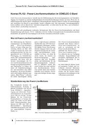
<strong>JControl</strong>/<strong>SmartDisplay</strong><br />
JAVA PROGRAMMABLE GRAPHIC LC-DISPLAY WITH 128X64 PIXEL,<br />
64K FLASH MEMORY, ANALOG KEYBOARD SUPPORT, RS232-<br />
INTERFACE, I²C-INTERFACE, 12 GPIO AND SOFT REALTIME SUPPORT<br />
� Virtual Machine Core<br />
� 8 Bit JAVA bytecode execution engine<br />
� 16 Bit processing word length<br />
� Max. 256 constant pool entries<br />
� 2.5k JAVA heap memory<br />
� 2 MIPS native core speed<br />
� Automatic garbage collection<br />
� Multi-threading support with extensions<br />
for soft realtime execution<br />
� Display<br />
� 128x64 pixel graphic LCD<br />
� FSTN technology<br />
� Optional backlight<br />
� Viewing area: 46.0 x 23.0 mm<br />
� Dot pitch: 0.36 mm<br />
� Display contrast and backlight adjustable<br />
by software<br />
� Flash Memory<br />
� up to 4 banks with 64k each<br />
� 128 or 256 byte per sector<br />
� > 10,000 erase/write cycles<br />
� Analog Keyboard<br />
� Decoder for up to 10 keys<br />
� Simple and cost-effective design with<br />
resistors<br />
� Only one GPIO occupied<br />
� Power-Supply<br />
� 3.3V or 5V power supply<br />
� Current consumption: max. 25mA<br />
(with backlight)<br />
� Buzzer Support<br />
� Controlled by PWM output<br />
© 2003-2006 <strong>DOMOLOGIC</strong> <strong>Home</strong> <strong>Automation</strong> <strong>GmbH</strong><br />
� RS232<br />
� 5-Wire RS232-Interface<br />
� 11 different baud rates from 300 up to<br />
250.000bps<br />
� None, even or odd parity<br />
� Automatic flow control by XON/XOFF or<br />
RTS/CTS<br />
� I²C/SMBus Communication<br />
� Master mode<br />
� 7 and 10 Bit addressing modes<br />
� I/O-Pins<br />
� Up to 12 General-Purpose I/O Pins<br />
� 2 I/Os usable as PWM outputs<br />
� 8 I/Os usable as Analog inputs<br />
� Physical Dimensions<br />
� Size: 76.2x41.9x9.5mm<br />
� Weight: 20g<br />
Version 1.3, September 2005<br />
1/18
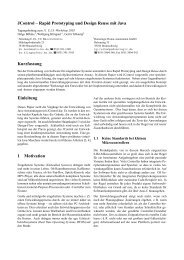
DIMENSIONS AND CONNECTORS<br />
1<br />
12<br />
DEVICE VARIANTS<br />
41.9mm<br />
Sales Type Power<br />
Supply<br />
76.2mm<br />
128x64 Graphic LCD<br />
Fig. 1: Dimensions and Connectors of the <strong>JControl</strong>/<strong>SmartDisplay</strong><br />
Native<br />
Core<br />
Speed<br />
Serial<br />
Baud Rates<br />
2/18 © 2003-2006 <strong>DOMOLOGIC</strong> <strong>Home</strong> <strong>Automation</strong> <strong>GmbH</strong><br />
<strong>JControl</strong>/<strong>SmartDisplay</strong><br />
Flash<br />
Organization<br />
Backlight<br />
JCSD10 NS15-2 5V 2 MIPS 300-250.000bps 512x128x1 none Soft<br />
JCSD10 BS15-2 5V 2 MIPS 300-250.000bps 512x128x1 blue Soft<br />
JCSD10 WS15-2 5V 2 MIPS 300-250.000bps 512x128x1 white Soft<br />
JCSD10 NS25-2 5V 2 MIPS 300-250.000bps 512x128x2 none Soft<br />
JCSD10 BS25-2 5V 2 MIPS 300-250.000bps 512x128x2 blue Soft<br />
JCSD10 WS25-2 5V 2 MIPS 300-250.000bps 512x128x2 white Soft<br />
JCSD10 NS45-2 5V 2 MIPS 300-250.000bps 256x256x4 none Soft<br />
JCSD10 BS45-2 5V 2 MIPS 300-250.000bps 256x256x4 blue Soft<br />
JCSD10 WS45-2 5V 2 MIPS 300-250.000bps 256x256x4 white Soft<br />
JCSD10 NS13-2 3,3V 2 MIPS 300-250.000bps 512x128x1 none Soft<br />
JCSD10 BS13-2 3,3V 2 MIPS 300-250.000bps 512x128x1 blue Soft<br />
JCSD10 WS13-2 3,3V 2 MIPS 300-250.000bps 512x128x1 white Soft<br />
JCSD10 NS23-2 3,3V 2 MIPS 300-250.000bps 512x128x2 none Soft<br />
JCSD10 BS23-2 3,3V 2 MIPS 300-250.000bps 512x128x2 blue Soft<br />
JCSD10 WS23-2 3,3V 2 MIPS 300-250.000bps 512x128x2 white Soft<br />
JCSD10 NS43-2 3,3V 2 MIPS 300-250.000bps 256x256x4 none Soft<br />
JCSD10 BS43-2 3,3V 2 MIPS 300-250.000bps 256x256x4 blue Soft<br />
JCSD10 WS43-2 3,3V 2 MIPS 300-250.000bps 256x256x4 white Soft<br />
Table 1: Derivatives of the <strong>JControl</strong>/<strong>SmartDisplay</strong><br />
24<br />
13<br />
RTC
<strong>JControl</strong>/<strong>SmartDisplay</strong><br />
GENERAL DESCRIPTION<br />
The <strong>JControl</strong>/<strong>SmartDisplay</strong> is a member of the<br />
<strong>JControl</strong> device family, designed as freely<br />
programmable LC-Display with 128x64 pixel and<br />
optional backlight, analog keyboard decoder,<br />
external buzzer control, communication ports<br />
(RS232 and I²C), general purpose I/Os, analog<br />
inputs and pulse width modulator outputs. All<br />
relevant signals are available by 24 pins at the left<br />
and right edge of the device (0.1” strip<br />
connectors). For evaluation purposes, an<br />
evaluation board is available.<br />
The <strong>JControl</strong>/<strong>SmartDisplay</strong> is based on the<br />
<strong>JControl</strong>/GUI-Engine processor. The integrated<br />
JCVM8 8 Bit JAVA bytecode execution engine<br />
runs with 2 MIPS native speed, providing 16 Bit<br />
processing word length, 2.5k JAVA heap memory,<br />
automatic garbage collection and multi-threading<br />
software execution. Applications in the field of<br />
control, measurement and automation are<br />
supported by specific extensions for soft-realtime<br />
processing.<br />
The JCVM8 offers a set of built-in classes,<br />
providing fundamental support of the JAVA<br />
programming language and access to all local<br />
peripheral components like LCD, analog<br />
keyboard, Flash memory etc. Extended support is<br />
given by class libraries, linked automatically to the<br />
application by the <strong>JControl</strong>/DevelopmentSuite.<br />
This mechanism saves memory space, because<br />
exclusively the required classes are loaded to the<br />
system.<br />
POWER SUPPLY AND SYSTEM RESET<br />
The <strong>JControl</strong>/<strong>SmartDisplay</strong> is powered by 5V DC<br />
or 3.3V DC, connected to the pins 12 (GND) and<br />
24 (VCC) of the device. To ensure a reliable start<br />
up phase, an integrated power-on reset generator<br />
(POR) holds the reset signal of the JCVM8 and<br />
LCD while the supply voltage is below the<br />
FLASH MEMORY ORGANIZATION<br />
Depending on the device variant, the<br />
<strong>JControl</strong>/<strong>SmartDisplay</strong> offers one to four banks of<br />
64k Flash memory for application software or nonvolatile<br />
data, labeled as Flash bank 0 to Flash<br />
bank 3. For devices with up to two flash banks,<br />
the memory is organized as 512 sectors by 128<br />
bytes, numbered from sector 0 to sector 511. For<br />
devices with 4 Flash bank, the memory is<br />
organized as 256 sectors by 256 bytes. The Flash<br />
memory’s organization may be detected<br />
automatically by reading the system property<br />
flash.format. The returned string comprises of<br />
RS232_TXD 1<br />
RS232_RXD 2<br />
RS232_RTS<br />
3<br />
RS232_CTS 4<br />
I2C_SCL 5<br />
I2C_SDA 6<br />
GPIO #0 / PWM #0 7<br />
GPIO #1 / PWM #1 8<br />
BACKLIGHT 9<br />
BUZZER 10<br />
11<br />
GND 12<br />
© 2003-2006 <strong>DOMOLOGIC</strong> <strong>Home</strong> <strong>Automation</strong> <strong>GmbH</strong><br />
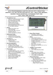
BACKLIGHT<br />
LCD<br />
128x64<br />
Pixels<br />
<strong>JControl</strong>VM<br />
(8bit)<br />
PWM #2<br />
PWM #3<br />
FLASH<br />
Memory<br />
POR<br />
Fig. 2: <strong>JControl</strong>/<strong>SmartDisplay</strong> Block Diagram<br />
Application programs are loaded via a serial<br />
communication interface to the Flash memory,<br />
which is organized as one to four banks of<br />
64kByte each. The banks may be used to store<br />
application software or non-volatile data.<br />
Various informations about the specific <strong>JControl</strong><br />
device and its current state is available by<br />
accessing the system properties. In download<br />
mode, the system properties may be read or<br />
written by remote using the <strong>JControl</strong> Download<br />
Protocol. Under normal operating conditions, the<br />
system properties can be accessed by application<br />
software using the methods getProperty and<br />
setProperty of the built-in class<br />
jcontrol.system.Management.<br />
threshold voltage of 4.50V or 3.00V resp. When<br />
the supply voltage exceeds the threshold voltage,<br />
the reset signal is released and the initialization<br />
sequence of the JCVM8 is executed. When<br />
finished, the JAVA-application stored in Flash bank<br />
0 is started.<br />
the parameters xx (e.g. "512x128x1" for the<br />
<strong>JControl</strong>/<strong>SmartDisplay</strong> device with one flash<br />
bank).<br />
The Flash memory can be used to store nonvolatile<br />
data using the built-in class<br />
jcontrol.io.Flash. It provides methods to<br />
read and write complete sectors in any bank of<br />
the Flash memory.<br />
/RESET<br />
+<br />
-<br />
4.20V<br />
24<br />
23<br />
VCC 22<br />
21<br />
RESET<br />
20 GPIO #2 / ADC #0<br />
19 GPIO #3 / ADC #1<br />
18 GPIO #4 / ADC #2<br />
17 GPIO #5 / ADC #3<br />
16 GPIO #6 / ADC #4<br />
15 GPIO #7 / ADC #5<br />
14 GPIO #8 / ADC #6<br />
13 GPIO #9 / ADC #7 / KB_IN<br />
3/18
Fig. 3 gives an overview of bank 0’s internal<br />
structure: Application software is written upwards,<br />
starting at physical sector 0 and non-volatile data<br />
is stored downwards, starting at physical sector<br />
510 (resp. 254 for devices with four flash banks).<br />
Logical Sector<br />
Sector 0<br />
Sector 1<br />
Sector 2<br />
Fig. 3: Internal Structure of Flash bank 0<br />
(For Devices with 1 or 2 Flash Banks with<br />
512 Sectors per Bank)<br />
DOWNLOAD MODE<br />
The system download mode is a fundamental<br />
functionality of the JCVM8, implemented in every<br />
<strong>JControl</strong> device. It is used for uploading<br />
application software to and downloading data from<br />
the Flash memory by a host computer, for auto<br />
identification of the <strong>JControl</strong> device and for<br />
reading or writing system properties by remote.<br />
The download mode is used e.g. by the<br />
development tools like <strong>JControl</strong>/IDE and<br />
PropertyEdit.<br />
The system download mode may be entered by<br />
one of following four cases:<br />
(1) Directly after the initialization sequence of the<br />
JCVM8: If no valid application software is<br />
available in bank 0 of the Flash memory, the<br />
device enters the system download mode.<br />
(2) During normal operating conditions: If the<br />
virtual machine is restarted by the method<br />
switchBank() of the built-in class<br />
jcontrol.system.Management and the<br />
new Flash bank contains no valid application<br />
software.<br />
GND<br />
<strong>JControl</strong>/<strong>SmartDisplay</strong><br />
Physical Sector<br />
Sector 511<br />
Sector 510<br />
Sector 509<br />
Sector 2<br />
Sector 1<br />
Sector 0<br />
KB_IN<br />
Fig. 5: Entering the System Download Mode<br />
� Pull signal KB_IN to GND (Pin 13), � activate RESET<br />
signal for more than 10ms (Pin 22)<br />
VCC<br />
+5V<br />
RESET<br />
"RESET"<br />
Properties<br />
Nonvolatile<br />
Data<br />
Application<br />
Software<br />
4/18 © 2003-2006 <strong>DOMOLOGIC</strong> <strong>Home</strong> <strong>Automation</strong> <strong>GmbH</strong><br />
<strong>JControl</strong>/<strong>SmartDisplay</strong><br />
This procedure reduces the possibility of resource<br />
conflicts between application software and data.<br />
To offer a linear ascending number of sectors<br />
(starting at sector 0) to the application, the class<br />
jcontrol.io.Flash maps access to the logical<br />
sector 0 to the physical sector 510 of the Flash<br />
memory, access to logical sector 1 to the physical<br />
sector 509 and so on. The uppermost sector of<br />
bank 0 (sector 511) is used to hold non-volatile<br />
system properties. The same principle is also<br />
used for Flash Bank 1, except that the uppermost<br />
sector is not holding the system properties.<br />
For applications using the flash memory<br />
independently of the memory architecture, the<br />
external class jcontrol.storage.<br />
FlashStream is provided. It represents a<br />
memory cached data stream for reading and<br />
writing continuous data to or from the non-volatile<br />
flash memory.<br />
Fig. 4: Splash screen of the system download mode<br />
(3) The system download mode may be enforced<br />
by pulling Pin 13 (GPIO #9/KB_IN) to GND<br />
while resetting the device (as shown in Fig. 5).<br />
Refer to the chapter covering the Analog<br />
Keyboard.<br />
(4) The mode may also be started by software<br />
calling the run()-Method of an instance of<br />
the built-in class<br />
jcontrol.system.Download.<br />
In the first three cases, a splash screen appears<br />
as shown in Fig. 4. The first line of the splash<br />
screen gives information about the <strong>JControl</strong><br />
device profile (“<strong>JControl</strong>/<strong>SmartDisplay</strong>”). The<br />
second line shows the build date of the JCVM8,<br />
represented as format yyyyMMddhhmm<br />
(yyyy=year, MM=month, dd=day, hh=hour,<br />
mm=minute). The following “+0100” in the example<br />
is optional and gives information about the time<br />
zone. The build date is also available as system<br />
property profile.date and used by the tools to<br />
select an appropriate device profile. The bottom<br />
line shows the parameters of the RS232 interface,<br />
fixed to 19200 bps, 8 data bits, no parity and 1<br />
stop bit.
<strong>JControl</strong>/<strong>SmartDisplay</strong><br />
Using the Download Mode by Applications<br />
The built-in class jcontrol.system.Download<br />
may be used to access or extend the download<br />
functionality by application software, e.g. to<br />
implement comfortable download or upload<br />
features for specific applications.<br />
DISPLAY<br />
The <strong>JControl</strong>/<strong>SmartDisplay</strong> comes with a 128x64<br />
pixel monochrome graphic LCD in FSTN<br />
technology, optionally backlighted by a blue or<br />
white LED. The display has a viewing direction of<br />
6 o’clock and is driven by a separate display<br />
controller (Samsung S6B1713), mounted as chipon-glass<br />
circuit on the top side of the component.<br />
To obtain a high data bandwidth, the<br />
communication between JCVM8 and display is<br />
realized by an 8 bit parallel interface.<br />
The built-in class jcontrol.io.Display offers<br />
a set of methods for drawing pixels, lines,<br />
rectangles, circles, images, characters and strings<br />
on the display. It implements the interface<br />
jcontrol.io.Graphics for hardware<br />
abstraction. Images are supported using the pixelbased<br />
<strong>JControl</strong> Image File format (JCIF, revision<br />
0001); fonts have to be formatted using the pixelbased<br />
<strong>JControl</strong> Font Definition format (JCFD,<br />
revision 0002). The class<br />
jcontrol.io.Display includes a proportional<br />
system font (8 pixel font height) by default.<br />
For detecting the display dimensions<br />
automatically, the system property<br />
display.dimensions returns a string<br />
comprising the parameters<br />
xx,<br />
specified by "128x64x1" for the<br />
ANALOG KEYBOARD<br />
The <strong>JControl</strong>/<strong>SmartDisplay</strong> provides a decoder for<br />
analog keyboards with up to 10 keys. Analog<br />
keyboards are designed as switched resistor<br />
ladders, generating a specific voltage for each<br />
key. This mechanism reduces the complexity<br />
required to realize a keyboard to a minimum.<br />
For the <strong>JControl</strong>/<strong>SmartDisplay</strong>, GPIO #9 is used<br />
for connecting the analog keyboard (this pin is<br />
also labeled as KB_IN). GPIO #9 is internally<br />
connected to the ADC #7 pin of the <strong>JControl</strong>/GUIengine.<br />
The system software measures the<br />
voltage at ADC #7 every 16ms, corresponding to<br />
a keyboard request rate of 62.5Hz. The class<br />
jcontrol.io.Keyboard provides methods for<br />
reading the switched resistor on character basis,<br />
© 2003-2006 <strong>DOMOLOGIC</strong> <strong>Home</strong> <strong>Automation</strong> <strong>GmbH</strong><br />
When the system download mode is started by<br />
software (see case 4), no splash screen appears<br />
and the baud rate is set to the value held by the<br />
system property rs232.baudrate (default:<br />
19200bps). When quitting, the download mode<br />
performs a system reset when data was written to<br />
the flash memory. Otherwise it returns to the<br />
calling application. See API documentation for<br />
more information about this class.<br />
<strong>JControl</strong>/<strong>SmartDisplay</strong> device. The coordinates of<br />
the display are organized from left to right and<br />
from top to bottom counting from 0 to size-1, see<br />
also Fig. 6.<br />
x<br />
y<br />
128x64<br />
Pixels<br />
Fig. 6: Coordinates used by the LCD-class<br />
The display contrast may be adjusted by software<br />
using the system property display.contrast.<br />
The value is saved to Flash memory, assuring<br />
that it will be restored by the system during powerup.<br />
The optional backlight LED of the display is<br />
controlled directly by the reserved PWM channel<br />
#2 of the <strong>JControl</strong>/GUI-Engine. For improved<br />
hardware abstraction, the external class<br />
jcontrol.io.Backlight is provided, enabling<br />
to set the backlight in 256 steps from 0 (off) to 255<br />
(max. brightness).<br />
including raw access, buffered access, automatic<br />
repetition and acoustic feedback.<br />
Fig. 7 shows the schematic of a simple cursorcontrol<br />
key panel connected to the<br />
<strong>JControl</strong>/<strong>SmartDisplay</strong>, realizing the keys up,<br />
down, left and right. The pull-up resistor R1<br />
(10kΩ) is used to apply a quiescent voltage of<br />
VDDA (analog reference voltage) to the analog<br />
channel, representing the passive state when all<br />
keys are released. Each keypress creates a<br />
specific voltage divider, composed by R1 and a<br />
chain of resistors from R2 to the resistor<br />
connected to the corresponding key. The resulting<br />
voltage is measured via ADC #7 (KB_IN).<br />
5/18
GPIO #9/KB_IN<br />
R1<br />
10kΩ<br />
+5V<br />
Table 2 lists the resistor values for an analog<br />
keyboard with up to 10 keys, using a pull-up<br />
resistor R1 of 10kΩ. The voltage created by the<br />
voltage dividers is increased by steps of VDDA/10,<br />
starting at 0V. Because of resistor tolerances, the<br />
resulting voltages and the measured ADC value<br />
may differ in real applications. Hence, the<br />
integrated keyboard decoder uses thresholds<br />
between two theoretical values for key detection.<br />
The keys decoded by the key panel shown in Fig.<br />
7 are ‘up’, ‘down’, ‘left’, ‘right’ and ‘select’,<br />
corresponding to the letters ‘U’, ‘D’, ‘L’, ‘R’ and ‘S’.<br />
The letters are returned by the method read() of<br />
the class jcontrol.io.Keyboard, when one of<br />
the keys is pressed. The letters are defined by the<br />
default keyboard map, that may be changed by an<br />
application program for software compatibility<br />
reasons.<br />
Note that the keys are prioritized, i. e. always the<br />
key with the lowest order number is decoded, if<br />
various keys are pressed simultaneously. The first<br />
REAL TIME CLOCK (RTC)<br />
The <strong>JControl</strong>/<strong>SmartDisplay</strong> implements a software<br />
emulated Real Time Clock (RTC), controlled by<br />
the system software. Hence, this “RTC” is clocked<br />
by the on-board ceramic resonator. It provides<br />
year, month, day, weekday, hours, minutes and<br />
seconds. Besides the current time, an alarm time<br />
is also provided. When the current time reaches<br />
the alarm time, a dedicated alarm flag is set.<br />
BUZZER CONTROL<br />
R2 R3 R4<br />
1100Ω 1300Ω 1800Ω<br />
'S' 'U' 'D' 'L'<br />
The <strong>JControl</strong>/<strong>SmartDisplay</strong> supports an external<br />
buzzer, connectable to pin 10 of the device. The<br />
buzzer may be used for acoustic signals<br />
generated by the system or by an application.<br />
The system will use the buzzer for acoustic<br />
feedback on keyboard events and for signalling<br />
system exceptions. Both features may be enabled<br />
or disabled by using the system properties<br />
Fig. 7: Schematic of a cursor-control analog key panel<br />
6/18 © 2003-2006 <strong>DOMOLOGIC</strong> <strong>Home</strong> <strong>Automation</strong> <strong>GmbH</strong><br />
R5<br />
2400Ω<br />
'R'<br />
<strong>JControl</strong>/<strong>SmartDisplay</strong><br />
key (letter ‘S’) is also used to enter the download<br />
mode when pressed during reset.<br />
Key<br />
Nr.<br />
more keys<br />
...<br />
Letter R Resistor<br />
Value<br />
'U'<br />
'D'<br />
V ADC<br />
Value<br />
1 ‘S’ 0Ω 0 0<br />
2 ‘U’ R2 1100Ω 0.5 25<br />
3 ‘D’ R3 1300Ω 1.0 50<br />
4 ‘L’ R4 1800Ω 1.5 76<br />
5 ‘R’ R5 2400Ω 2.0 102<br />
6 ‘N’ R6 3300Ω 2.5 127<br />
7 ‘P’ R7 5100Ω 3.0 153<br />
8 ‘E’ R8 8200Ω 3.5 179<br />
9 ‘H’ R9 16000Ω 4.0 204<br />
10 ‘X’ R10 51000Ω 4.5 230<br />
Table 2: Resistor values for the Analog Keyboard<br />
'S'<br />
'L' 'R'<br />
Analog keyboards are not suitable for silicone<br />
rubber keys, because of their varying and<br />
pressure-dependent contact resistances. Use<br />
external hardware, e.g. logic buffers, to reduce the<br />
contact resistance in this case.<br />
The built-in class jcontrol.system.RTC<br />
implements methods for reading and writing the<br />
current time and the alarm time. A time<br />
information is represented by an instance of the<br />
built-in class jcontrol.system.Time,<br />
combining the fields year, month, day, weekday,<br />
hours, minutes and seconds.<br />
buzzer.systembeep (system execeptions) and<br />
buzzer.keyboardbeep. Additionally, an<br />
application software may control the buzzer using<br />
the external class jcontrol.io.Buzzer,<br />
implementing the interface<br />
jcontrol.io.SoundDevice for hardware<br />
abstraction. This class provides methods to<br />
activate the buzzer using a specified frequency<br />
(250...32767Hz) for a specified duration (in ms).
<strong>JControl</strong>/<strong>SmartDisplay</strong><br />
The system property buzzer.enable is provided<br />
to enable or disable the buzzer when it is used by<br />
an application. Furthermore, the external class<br />
jcontrol.toolkit.iMelody is provided,<br />
playing complete melodies given by the iMelody-<br />
Format (IMY, published by the Infrared Data<br />
Association, IrDA). The buzzer output is<br />
connected internally to the reserved PWM<br />
channel #3 of the <strong>JControl</strong>/GUI-engine.<br />
RS232 COMMUNICATION<br />
The <strong>JControl</strong>/<strong>SmartDisplay</strong> provides a serial<br />
communication interface with CMOS/TTL levels.<br />
The signals are available at pin 1 (output signal<br />
TXD) and pin 2 (input signal RXD) of the device.<br />
Optionally, two signals for flow control are<br />
available at pin 3 (output signal RTS) and pin 4<br />
(input signal CTS).<br />
The built-in class jcontrol.comm.RS232<br />
provides methods for reading, writing and<br />
configuring the RS232 interface. It supports<br />
buffered read access and operates on byte,<br />
char, string and utf8 basis. Automatic<br />
echoing is also supported by the readLine()<br />
method.<br />
The RS232 communication interface supports 11<br />
different baud rates, starting from 300 up to<br />
250.000bps including the MIDI-baud rate of<br />
31250bps. The baud rate is changed using the<br />
method setBaudrate() of the built-in class<br />
jcontrol.comm.RS232 (see Table 3 for a list of<br />
all valid settings). If an application attempts to set<br />
an unsupported baud rate, always the fall-back<br />
setting 19200bps is used. If no baud rate value is<br />
set by the application, the default value specified<br />
by the system property rs232.baudrate is<br />
used.<br />
Baud Rate Parameter for<br />
setBaudrate<br />
Comment<br />
300 300<br />
600 600<br />
1200 1200<br />
2400 2400<br />
4800 4800<br />
9600 9600<br />
19.200 19200 Fall-back setting<br />
31.250 31250 MIDI<br />
62.500 62<br />
125.000 125<br />
250.000 250<br />
Table 3: Supported Baud Rates<br />
© 2003-2006 <strong>DOMOLOGIC</strong> <strong>Home</strong> <strong>Automation</strong> <strong>GmbH</strong><br />
As a buzzer, a simple piezo element may be<br />
used, connected directly to Pin 10 of the<br />
<strong>JControl</strong>/<strong>SmartDisplay</strong>. If a magnetic loudspeaker<br />
is used, please provide a transistor for boosting<br />
the output signal and a free wheeling diode to<br />
block reverse voltages generated by the coil.<br />
Additionally, the RS232 communication interface<br />
supports a parity bit (9 th data bit) as well as flow<br />
control (by XON/XOFF or RTS/CTS). All options<br />
are defined by the current communication<br />
parameters, configured using method<br />
setParams() of the built-in class<br />
jcontrol.comm.RS232. As shown in Fig. 8, the<br />
options are combined to a single bitmask.<br />
Appropriate constant field values are defined by<br />
the class jcontrol.comm.RS232. When the<br />
parameters are not changed by the application<br />
software, always the default settings specified by<br />
the system property rs232.params are used.<br />
The following parity modes are supported: “8N1”<br />
(8 data bits, no parity, 1 stop bit), “8E1” (8 data<br />
bits, even parity, 1 stop bit) and “8O1” (8 data bits,<br />
odd parity, 1 stop bit). For flow control, two<br />
different modes are supported: Software flow<br />
control (by XON/XOFF) and hardware flow control<br />
(by RTS/CTS). Software flow control uses the<br />
ASCII-codes XON (0x11) and XOFF (0x13).<br />
Hardware flow control is realized by the external<br />
signals RS232_RTS (pin 3) and RS232_CTS (pin<br />
4) of the <strong>JControl</strong>/<strong>SmartDisplay</strong>.<br />
MSB<br />
64 32<br />
16<br />
f f<br />
8<br />
e<br />
4<br />
2<br />
1<br />
p p<br />
LSB<br />
Parity<br />
00 = No Parity ( N)<br />
01 = Even Parity ( E)<br />
10 = Odd Parity ( O)<br />
11 = Reserved<br />
Echo<br />
0 = Echo disabled<br />
1 = Echo enabled<br />
Flow Control<br />
00 = None<br />
01 = XON/XOFF<br />
10 = RTS/CTS<br />
11 = Reserved<br />
Fig. 8: RS232 Communication Parameters<br />
7/18
I/O PINS (GPIO, PWM, ADC)<br />
The <strong>JControl</strong>/<strong>SmartDisplay</strong> provides 12 general<br />
purpose I/O (GPIO) signals for external hardware<br />
control, numbered as GPIO #0 to GPIO #11. The<br />
built-in class jcontrol.io.GPIO is provided to<br />
control the I/Os, supporting four different<br />
configuration modes:<br />
� FLOATING: Standard digital input<br />
� PULLUP: Digital input with integrated pull up<br />
resistor (60k-240kΩ, cannot be influenced)<br />
� PUSHPULL: Standard digital output<br />
� OPENDRAIN: Digital output, set to highimpedance<br />
state when HIGH<br />
The output current of any pin must not exceed<br />
25mA, independent of its usage (either source or<br />
sink).<br />
Four pins are connected to an integrated Pulse<br />
Width Modulator (PWM), which provides a<br />
resolution of up to 8 bits. This feature is controlled<br />
by the built-in class jcontrol.io.PWM. The<br />
generated signals are available via the PWM<br />
channels 0 to 3. The device uses a single<br />
frequency generator for all channels, hence the<br />
frequency of the channels has to be the same.<br />
The duty cycle of each PWM channel may be<br />
8/18 © 2003-2006 <strong>DOMOLOGIC</strong> <strong>Home</strong> <strong>Automation</strong> <strong>GmbH</strong><br />
<strong>JControl</strong>/<strong>SmartDisplay</strong><br />
adjusted individually. Please note that every pin<br />
configured as PWM output is not available as<br />
GPIO. ATTENTION: PWM channel 2 is hardwired<br />
to the backlight LED of the LCD, which may have<br />
an effect on peripheral hardware connected to this<br />
pin.<br />
Furthermore, eight pins are connected to the<br />
internal 8-bit A/D converter and may be used as<br />
analog inputs. The built-in class<br />
jcontrol.io.ADC is provided to control this<br />
feature. When a pin is used as analog input, it<br />
should be configured to FLOATING mode using<br />
the class jcontrol.io.GPIO. The reference<br />
voltage for the ADC channels must be connected<br />
to pins VDDA (high potential; pin 23) and GND (low<br />
potential; pin 12) and may not exceed the supply<br />
voltage.<br />
Table 4 provides an overview on the features of<br />
each pin described here. Two of the listed GPIOs<br />
(#10 and #11) are provided to control the RS232<br />
hardware flow signals RTS and CTS. Refer to<br />
chapter “RS232 Communication” for more<br />
information about this topic.<br />
See the datasheet “<strong>JControl</strong>/GUI-Engine” for<br />
further information about the GPIOs.<br />
Device<br />
Pin1) GPIO # PWM # ADC # Alternate<br />
function<br />
GPIO<br />
configurations 2)<br />
7 0 0 - - FI, PU, OD, PP<br />
8 1 1 - - FI, PU, OD, PP<br />
20 2 - 0 - FI, PU, OD, PP<br />
19 3 - 1 - FI, PU, OD, PP<br />
18 4 - 2 - FI, PU, OD, PP<br />
17 5 - 3 - FI, PU, OD, PP<br />
16 6 - 4 - FI, PU, OD, PP<br />
15 7 - 5 - FI, PU, OD, PP<br />
14 8 - 6 - FI, PU, OD, PP<br />
13 9 - 7 KB_IN FI, PU, OD, PP<br />
3 10 - - RS232_RTS PU<br />
4 11 - - RS232_CTS FI, PU, OD, PP<br />
- 122) - - - FI, PU, OD, PP<br />
- 133) - - - FI, PU, OD, PP<br />
9 - 2 - /BACKLIGHT -<br />
10 - 3 - BUZZER -<br />
Table 4: Features of universal I/O pins<br />
1) A ‘-‘ indicates, that this GPIO is present but not available via a device pin. (For more information see datasheet: <strong>JControl</strong>/GUI-Engine)<br />
2) FI = FLOATING input ; PU = Input with internal PULLUP resistor ; PP = PUSHPULL output ; OD = OPENDRAIN output<br />
3) Reserved for internal use
<strong>JControl</strong>/<strong>SmartDisplay</strong><br />
I²C COMMUNICATION<br />
A I²C/SMBus communication interface is available<br />
at the port of the <strong>JControl</strong>/<strong>SmartDisplay</strong>.<br />
The I 2 C bus is a de facto standard for on-board<br />
inter-IC communication. It was developed by<br />
Philips Semiconductors in the early 1980's. Many<br />
integrated circuits are supporting the I²C bus.<br />
SMBus is a kind of extended I²C bus, developed<br />
by Intel in 1995 as System Management Bus. It is<br />
used e.g. in personal computers and servers for<br />
low-speed system management communications.<br />
Mostly, the SMBus is used to interconnect the<br />
sensors for temperatures, voltages, rotation speed<br />
of fans etc.<br />
The built-in class jcontrol.comm.I2C provides<br />
methods for using the <strong>JControl</strong> device as bus<br />
JCVM8 RESTRICTIONS<br />
Not all JAVA features are implemented by the<br />
JCVM8. The following list gives an overview on<br />
the restrictions:<br />
� Data type int is limited to 16 bit processing<br />
word length (not 32 bit)<br />
� Data types long, float and double are not<br />
implemented. When used, one of the following<br />
two error codes is generated (context<br />
dependent):<br />
� BytecodeNotSupportedError (6)<br />
� UnsupportedArrayTypeError (9)<br />
� The number of constants in the constant pool<br />
is limited to 255 (will be checked by the<br />
JCManager before upload)<br />
© 2003-2006 <strong>DOMOLOGIC</strong> <strong>Home</strong> <strong>Automation</strong> <strong>GmbH</strong><br />
master. It supports 7 bit and 10 bit addressing<br />
schemes as well as reading and writing single<br />
chars or byte streams. It implements a simple<br />
hardware layer, therefore any bus error and any<br />
arbitration lost results in an IOException after a<br />
few retries. To avoid blocking, the class<br />
implements a bus timeout (in contrast to the I²C<br />
bus specification).<br />
The signal I²C_SCL (pin 5) is the clock signal of<br />
the I²C bus (or SMBCLK of SMBus). The signal<br />
I²C_SDA (pin 6) is the data signal of the I²C bus<br />
(or SMBDAT of SMBus).<br />
� Cast check for primitive arrays is not<br />
supported and causes an error<br />
(NotImplementedError)<br />
� It is not possible to call object methods on<br />
primitive arrays, e.g.<br />
new int[25].equals(myObject)<br />
� Some exceptions can not be catched by an<br />
application, because they generate an error<br />
code. When thrown, the JCVM8 is restarted in<br />
error condition and the error handler is called<br />
(see also chapter Error Codes).<br />
� Implementation of classes in the package<br />
java.lang is incomplete (see <strong>JControl</strong><br />
JAVADOC)<br />
9/18
ERROR CODES<br />
When an exception is thrown and not handled by<br />
the application, the JCVM8 generates an error<br />
code. Some of the errors (listed in the following<br />
Table 5) are specific to the JCVM8 and not<br />
common in the JAVA programming language<br />
(labeled with 1 ). Other error codes are masked<br />
exceptions, because they are generated instead<br />
of an exception (labeled with 2 ).<br />
Every error restarts the JCVM8 in error condition.<br />
Afterwards the method onError() of the built-in<br />
10/18 © 2003-2006 <strong>DOMOLOGIC</strong> <strong>Home</strong> <strong>Automation</strong> <strong>GmbH</strong><br />
<strong>JControl</strong>/<strong>SmartDisplay</strong><br />
class jcontrol.system.ErrorHandler is<br />
invoked. More details about the error state is<br />
passed by parameters to the onError() method.<br />
The built-in error handler may be overwritten by a<br />
user-defined error handler stored in Flash bank 0.<br />
See the error handler included in the<br />
SystemSetup software for demonstration.<br />
Following table gives an overview on the error<br />
codes generated by the JCVM8.<br />
ID Name Description<br />
1 HandleError 1)<br />
Internal VM error<br />
2 NullPointerException 2)<br />
Attempt to use NULL where an object is required<br />
3 OutOfMemoryError Generated when no memory is available<br />
4 BytecodeNotAvailableError 1)<br />
Attempt to execute an invalid bytecode<br />
5 BytecodeNotSupportedError 1)<br />
Attempt to execute an unsupported bytecode, e.g.<br />
bytecodes for 64-bit arithmetic or floating point<br />
processing<br />
6 BytecodeNotDefinedError 1)<br />
Attempt to execute an undefined bytecode<br />
7 ArithmeticException 2)<br />
Exception during arithmetic processing, e.g. division<br />
by zero<br />
8 NegativeArraySizeException 2)<br />
Attempt to create an array with negative size<br />
9 UnsupportedArrayTypeError 1)<br />
Arrays of this type are not supported<br />
10 ArrayIndexOutOfBoundsException 2)<br />
Array index is out of bounds<br />
11 ClassCastException 2)<br />
Attempt to cast an object which is not of an<br />
appropriate runtime type<br />
12 NoCodeError 1)<br />
Thrown when a method is called that implements no<br />
code<br />
13 WaitForMonitorSignal 1)<br />
Used internally by the VM<br />
14 ExternalNativeError 1)<br />
Generated when a native method is called that is not<br />
stored in ROM<br />
15 FatalStackFrameOverflowError 1)<br />
Generated when the stack size is not sufficent<br />
16 InstantiationException 2)<br />
Attempt to instantiate an abstract class or interface<br />
17 IllegalMonitorStateException 2)<br />
E.g. when a wait is called without an appropriate<br />
monitor<br />
18 UnsatisfiedPrelinkError 1)<br />
Error due to a failed prelinking process<br />
19 ClassFormatError 1)<br />
Generated by an invalid class<br />
20 ClassTooBigError 1)<br />
The size of a class exceeds the limitations<br />
21 PreLinkError 1)<br />
Error due to a failed prelinking process<br />
22 PreLinkedUnresolvedError 1)<br />
Error due to a failed prelinking process<br />
23 UnsupportedConstantTypeError 1)<br />
Generated when the type of a constant is not<br />
supported by the JCVM8 (long, float or double)<br />
24 MalformatedDescriptorError 1)<br />
Error while dereferencing constant pool, e.g. due to<br />
wrong class file format<br />
25 RuntimeRefTableOverrunError 1)<br />
More class references used than specified in a class<br />
file<br />
26 NoSuchFieldError Referenced field not found<br />
27 IllegalAccessError Tried to access a field or method from wrong scope<br />
(e.g. private)<br />
28 NoSuchMethodError Could not find referenced method<br />
29 TooMuchParametersError 1)<br />
A method uses more parameters than supported by<br />
the JCVM8 (max. 16)<br />
30 ThrowFinalError 1)<br />
Uncatched user defined exception. Exception name
<strong>JControl</strong>/<strong>SmartDisplay</strong><br />
ID Name Description<br />
is passed to the onError() method<br />
31 NoClassDefFoundError 1)<br />
Unable to find a class by name<br />
32 IndexOutOfBoundsException 2)<br />
Thrown by some methods using String or array<br />
parameters and indices that are out of bounds<br />
33 ArrayDimensionError 1)<br />
Generated when an array is created with more than<br />
2 dimensions (only 1 and 2 dimensions supported)<br />
34 DeadlockError 1)<br />
Generated by the JCVM8 scheduler when two or<br />
more threads inheriting from each other<br />
35 IncompatibleClassChangeError Generated when an interface is invoked for an<br />
object, that is not implementing the interface<br />
36 NotImplementedError 1)<br />
Generated when an unimplemented JAVA feature is<br />
used<br />
Table 5: Error Codes generated by the JCVM8<br />
1) Error codes generated exclusively by the JCVM8. Not common in the JAVA programming language.<br />
2) JCVM8 error codes generated by the JCVM8 instead of exceptions. Cannot be handled by an exception handler. May be replaced by<br />
JAVA exceptions in future revisions of the JCVM8.<br />
SYSTEM PROPERTIES<br />
System properties providing specific information<br />
about the <strong>JControl</strong> device. All properties are<br />
identified by a fixed string (the content is always<br />
formatted as string). The properties may be read<br />
or written using the methods getProperty()<br />
and setProperty() of the built-in class<br />
jcontrol.system.Management. In download<br />
mode, the tool PropertyEdit may be used to read<br />
or write the properties by remote.<br />
© 2003-2006 <strong>DOMOLOGIC</strong> <strong>Home</strong> <strong>Automation</strong> <strong>GmbH</strong><br />
The system properties are categorized into ROM<br />
properties and non-volatile properties. ROM<br />
properties are stored in read-only memory of the<br />
device and can not be changed. Non-volatile<br />
properties are held in the upper sector of Flash<br />
bank 0 and may be changed by software.<br />
Key Type Value Description<br />
profile.name String “<strong>JControl</strong>/<strong>SmartDisplay</strong>” <strong>JControl</strong> Profile Name<br />
profile.date String “{yyyyMMddhhmm}" Date of JCVM build<br />
system.heapsize Int 2688 Size of internal JAVA heap memory<br />
flash.format String “512x128x1” Flash Organization<br />
(bytes x blocks x banks)<br />
io.gpiochannels Int 14 Number of GPIO channels<br />
io.pwmchannels Int 4 Number of PWM channels<br />
io.adcchannels Int 8 Number of ADC channels<br />
display.dimensions String “128x64x1” Display dimensions<br />
(width x height x colour_depth)<br />
Table 6: ROM Properties (saved in ROM, read access only)<br />
Key Type Range Default Description<br />
system.userbank Int 0..1 0 Flash bank used for user application<br />
rtc.poweronbank Int 0..1 0 Bank selected to start application after<br />
power on initiated by RTC alarm<br />
buzzer.enable Bool true, false true Enable or disable buzzer to be used by<br />
application software<br />
buzzer.systembeep Bool true, false true Enable or disable system sound<br />
(set independent from buzzer.enable)<br />
11/18
Key Type Range Default Description<br />
12/18 © 2003-2006 <strong>DOMOLOGIC</strong> <strong>Home</strong> <strong>Automation</strong> <strong>GmbH</strong><br />
<strong>JControl</strong>/<strong>SmartDisplay</strong><br />
buzzer.keyboardbeep Bool true, false true Enable or disable keyboard beep<br />
(set independent from buzzer.enable)<br />
display.contrast Int 0..255 42 LCD contrast adjustment<br />
rs232.params Int (see section<br />
RS232<br />
Communication:<br />
Figure 8)<br />
rs232.baudrate Int (see section<br />
RS232<br />
Communication:<br />
Table 3)<br />
SUPPORTED DATA FORMATS<br />
The device supports following data formats:<br />
Format<br />
used for<br />
Format<br />
suffix<br />
0 Bitmask holding RS232 configuration<br />
� Bit 1:0 00 = No Parity<br />
01 = PARITY_EVEN enabled<br />
10 = PARITY_ODD enabled<br />
� Bit 3 1 = ECHO enabled<br />
� Bit 5:4 00 = No flow control<br />
01 =<br />
FLOWCONTROL_XONOFF<br />
enabled<br />
10 =<br />
FLOWCONTROL_RTSCTS enabled<br />
19200 Sets default RS232 Baudrate<br />
Table 7: Non-Volatile Properties (saved in Flash, read and write access)<br />
Rev. Description Used by class Editor<br />
Images JCIF 0001 <strong>JControl</strong> Image File<br />
8-Bit pixel-based image<br />
definition format<br />
Fonts JCFD 0002 <strong>JControl</strong> Font Definition<br />
8-Bit pixel-based font<br />
definition format<br />
Melodies IMY V1.2 iMelody<br />
Melody format specified<br />
by Infrared Data<br />
Association (IrDA)<br />
jcontrol.io.Display PictureEdit<br />
jcontrol.io.Display FontEdit<br />
Table 8: Supported Data Formats for the <strong>JControl</strong>/<strong>SmartDisplay</strong><br />
The format specifications are available online at http://www.jcontrol.org.<br />
jcontrol.toolkit.iMelody MelodyEdit
<strong>JControl</strong>/<strong>SmartDisplay</strong><br />
BUILT-IN PACKAGES<br />
Summary of Packages<br />
Package Description<br />
jcontrol.comm Complex communication features for <strong>JControl</strong>.<br />
jcontrol.io Classes for basic I/O and peripheral control.<br />
jcontrol.lang Replacement classes, fundamental to the design of the JAVA programming<br />
language.<br />
jcontrol.system <strong>JControl</strong> core classes and <strong>JControl</strong> specific JAVA extensions.<br />
java.lang Provides classes that are fundamental to the design of the Java programming<br />
language. Subset of the standard-package java.lang.<br />
java.io Subset of the standard java.io-package<br />
(only java.io.IOException)<br />
Packages in Detail<br />
Name Type Description<br />
Package jcontrol.comm<br />
ConsoleInputStream Interface Provides a set of high-level communication methods to read<br />
from a console.<br />
ConsoleOutputStream Interface Provides a set of high-level communication methods to write<br />
to a console<br />
RS232 Class Implements RS232 communication for <strong>JControl</strong><br />
Package jcontrol.io<br />
ADC Class Control of <strong>JControl</strong>s analog-digital converter. Used to<br />
measure the voltage at portpins connected to the internal A/D<br />
converter<br />
BasicInputStream Interface Interface providing a set of low-level communication methods<br />
for reading from a stream<br />
BasicOutputStream Interface Interface providing a set of low-level communication methods<br />
for writing to a stream<br />
ComplexInputStream Interface Interface providing a set of high-level communication methods<br />
for reading from a stream<br />
ComplexOutputStream Interface Interface providing a set of high-level communication methods<br />
for writing to a stream<br />
Display Class Class to control the on-board 128x64 BW-LC-Display.<br />
Coordinates are from left to right and from top to bottom<br />
counting from 0 to size-1.<br />
Drawable Interface Defines Object-behaviour for use with<br />
jcontrol.io.Display.drawImage()<br />
File Interface Provides a set of methods for file-system access<br />
Flash Class Raw access to <strong>JControl</strong>’s integrated Flash memory. The<br />
methods are designed to access complete sectors of memory,<br />
not single bytes.<br />
Graphics Interface Interface definition for graphics devices<br />
(e.g. offscreen images, displays, ...)<br />
I2C Class Controls I 2 C devices connected to <strong>JControl</strong>.<br />
Keyboard Class Accesses <strong>JControl</strong>’s keyboard, the analog keyboard in the<br />
case of the <strong>JControl</strong>/<strong>SmartDisplay</strong><br />
Portpins Class Controls available portpins of <strong>JControl</strong><br />
PWM Class Controls the Pulse Width Modulation outputs of <strong>JControl</strong><br />
© 2003-2006 <strong>DOMOLOGIC</strong> <strong>Home</strong> <strong>Automation</strong> <strong>GmbH</strong><br />
13/18
Name Type Description<br />
14/18 © 2003-2006 <strong>DOMOLOGIC</strong> <strong>Home</strong> <strong>Automation</strong> <strong>GmbH</strong><br />
<strong>JControl</strong>/<strong>SmartDisplay</strong><br />
Resource Class Implements read access to the application’s resource. The<br />
resource stores additional application data like pictures, fonts,<br />
text etc.<br />
Package jcontrol.lang<br />
Deadline Class Constructs a new <strong>JControl</strong> deadline, useful for soft real-time<br />
applications<br />
ThreadExt Class Thread extensions for <strong>JControl</strong>, useful for soft real-time<br />
applications<br />
Math Class Provides some simple math functions<br />
Package jcontrol.system<br />
Download Class Manages to download new JAVA applications to a <strong>JControl</strong><br />
module<br />
ErrorHandler Class The <strong>JControl</strong> Error-Handler. May be overwritten to implement<br />
more comfortable error handlers.<br />
Management Class Controls various system management functions<br />
RTC Class Access to <strong>JControl</strong>’s integrated Real Time Clock<br />
Time Class The Time object stores a date and time.<br />
Package java.lang<br />
Exception Class The class Exception and its subclasses are a form of<br />
Throwable, indicating conditions that a reasonable<br />
application might want to catch<br />
Integer Class The Integer class wraps a value of the primitive type int in<br />
an object. An object of type Integer contains a single field<br />
whose type is int.<br />
Object Class Class Object is the root of the class hierarchy. Every class<br />
has Object as a superclass. All objects, including arrays,<br />
implement the methods of this class.<br />
Runnable Interface The Runnable interface should be implemented by any class<br />
whose instances are intended to be executed by a thread. The<br />
class must define a method of no arguments called run.<br />
String Class The String class represents character strings. All string<br />
literals in JAVA programs, such as "abc", are implemented as<br />
instances of this class<br />
Thread Class A Thread is a thread of execution in a program. The JAVA<br />
Virtual Machine allows an application to have multiple threads<br />
of execution running concurrently.<br />
Throwable Class The Throwable class is the superclass of all errors and<br />
exceptions in the JAVA language. Only objects that are<br />
instances of this class (or one of its subclasses) are thrown by<br />
the JAVA Virtual Machine or can be thrown by the JAVA throw<br />
statement. Similarly, only this class or one of its subclasses<br />
can be the argument type in a catch clause.
<strong>JControl</strong>/<strong>SmartDisplay</strong><br />
MECHANICAL DATA<br />
41.9<br />
2<br />
1<br />
12<br />
2.54<br />
PIN ASSIGNMENT<br />
2.54<br />
2.54<br />
6.35<br />
76.2<br />
71.1<br />
6.35<br />
2.54<br />
Fig. 9: Mechanical Data of <strong>JControl</strong>/<strong>SmartDisplay</strong><br />
(All sizes in mm)<br />
Pin Name Description<br />
1 RS232_TXD Transmit Data output of RS232 interface<br />
2 RS232_RXD Receive Data input of RS232 interface<br />
3 GPIO #10 � GPIO channel #10<br />
RS232_RTS � Input modes: PULLUP<br />
� Output modes: -<br />
� Ready To Send handshake output of RS232 interface<br />
4 GPIO #11 � GPIO channel #11<br />
RS232_CTS � Input modes: FLOATING or PULLUP<br />
� Output modes: PUSHPULL or OPENDRAIN<br />
� Clear To Send handshake input of RS232 interface<br />
5 I²C_SCL Clock Signal of I²C-Bus (SMBCLK of SMBus)<br />
6 I²C_SDA Data Signal of I²C-Bus (SMBDAT of SMBus)<br />
7 GPIO #0 � GPIO channel #0<br />
PWM #0<br />
� Input modes: FLOATING or PULLUP<br />
� Output modes: PUSHPULL or OPENDRAIN<br />
� PWM channel #0<br />
© 2003-2006 <strong>DOMOLOGIC</strong> <strong>Home</strong> <strong>Automation</strong> <strong>GmbH</strong><br />
2.54<br />
24<br />
13<br />
35.6<br />
15/18
Pin Name Description<br />
8 GPIO #1<br />
PWM #1<br />
9 PWM #2<br />
/BGLIGHT<br />
10 PWM #3<br />
BUZZER<br />
� GPIO channel #1<br />
� Input modes: FLOATING or PULLUP<br />
� Output modes: PUSHPULL or OPENDRAIN<br />
� PWM channel #1<br />
� PWM channel #2<br />
� BACKLIGHT LED control output<br />
16/18 © 2003-2006 <strong>DOMOLOGIC</strong> <strong>Home</strong> <strong>Automation</strong> <strong>GmbH</strong><br />
<strong>JControl</strong>/<strong>SmartDisplay</strong><br />
� Internally connected to PWM channel #2 and to the LCD backlight LED<br />
� PWM channel #3<br />
� Buzzer control output<br />
� Internally connected to PWM channel #3<br />
11 n/c reserved for future use<br />
12 GND Ground Voltage (also low potential of the analog reference voltage)<br />
13 GPIO #9<br />
ADC #7<br />
KB_IN<br />
14 GPIO #8<br />
ADC #6<br />
15 GPIO #7<br />
ADC #5<br />
16 GPIO #6<br />
ADC #4<br />
17 GPIO #5<br />
ADC #3<br />
18 GPIO #4<br />
ADC #2<br />
19 GPIO #3<br />
ADC #1<br />
20 GPIO #2<br />
ADC #0<br />
� GPIO channel #9<br />
� Input modes: FLOATING or PULLUP<br />
� Output modes: PUSHPULL or OPENDRAIN<br />
� ADC channel #7<br />
� Analog Keyboard Input<br />
� GPIO channel #8<br />
� Input modes: FLOATING or PULLUP<br />
� Output modes: PUSHPULL or OPENDRAIN<br />
� ADC channel #6<br />
� GPIO channel #7<br />
� Input modes: FLOATING or PULLUP<br />
� Output modes: PUSHPULL or OPENDRAIN<br />
� ADC channel #5<br />
� GPIO channel #6<br />
� Input modes: FLOATING or PULLUP<br />
� Output modes: PUSHPULL or OPENDRAIN<br />
� ADC channel #4<br />
� GPIO channel #5<br />
� Input modes: FLOATING or PULLUP<br />
� Output modes: PUSHPULL or OPENDRAIN<br />
� ADC channel #3<br />
� GPIO channel #4<br />
� Input modes: FLOATING or PULLUP<br />
� Output modes: PUSHPULL or OPENDRAIN<br />
� ADC channel #2<br />
� GPIO channel #3<br />
� Input modes: FLOATING or PULLUP<br />
� Output modes: PUSHPULL or OPENDRAIN<br />
� ADC channel #1<br />
� GPIO channel #2<br />
� Input modes: FLOATING or PULLUP<br />
� Output modes: PUSHPULL or OPENDRAIN<br />
� ADC channel #0<br />
21 n/c reserved for future use<br />
22 /RESET Reset input, active low<br />
23 VDDA<br />
Reference voltage for ADC channels (high potential)<br />
24 VCC<br />
Power Supply (5V or 3.3V DC)<br />
Table 9: Pin Assignment of <strong>JControl</strong>/<strong>SmartDisplay</strong>
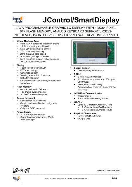
<strong>JControl</strong>/<strong>SmartDisplay</strong><br />
1<br />
2<br />
3<br />
4<br />
5<br />
D D<br />
C C<br />
Fig. 10: Schematic of the <strong>JControl</strong>/<strong>SmartDisplay</strong><br />
© 2003-2006 <strong>DOMOLOGIC</strong> <strong>Home</strong> <strong>Automation</strong> <strong>GmbH</strong><br />
B B<br />
A A<br />
1<br />
2<br />
3<br />
4<br />
5<br />
17/18
NOTES<br />
18/18 © 2003-2006 <strong>DOMOLOGIC</strong> <strong>Home</strong> <strong>Automation</strong> <strong>GmbH</strong><br />
<strong>JControl</strong>/<strong>SmartDisplay</strong><br />
Information furnished is believed to be accurate and reliable. However, <strong>DOMOLOGIC</strong> <strong>Home</strong> <strong>Automation</strong> <strong>GmbH</strong> assumes no<br />
responsibility for the consequences of use such information nor for any infringement of patents or other rights of third parties which may<br />
result from its use. No license is granted by implication or otherwise under any patent or patent rights of <strong>DOMOLOGIC</strong> <strong>Home</strong><br />
<strong>Automation</strong> <strong>GmbH</strong>. Specifications mentioned in this publication are subject of change without notice. This publication supersedes and<br />
replaces information previously supplied. <strong>DOMOLOGIC</strong> <strong>Home</strong> <strong>Automation</strong> <strong>GmbH</strong> products are not authorized to use as critical<br />
components in life support devices or systems without express written approval of <strong>DOMOLOGIC</strong> <strong>Home</strong> <strong>Automation</strong> <strong>GmbH</strong>.<br />
© 2003-2006 <strong>DOMOLOGIC</strong> <strong>Home</strong> <strong>Automation</strong> <strong>GmbH</strong> – All Rights Reserved