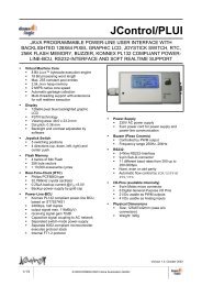
JControl/SmartDisplay - DOMOLOGIC Home Automation GmbH
JControl/SmartDisplay - DOMOLOGIC Home Automation GmbH
JControl/SmartDisplay - DOMOLOGIC Home Automation GmbH

You also want an ePaper? Increase the reach of your titles
YUMPU automatically turns print PDFs into web optimized ePapers that Google loves.
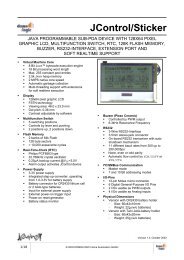
I/O PINS (GPIO, PWM, ADC)<br />
The <strong>JControl</strong>/<strong>SmartDisplay</strong> provides 12 general<br />
purpose I/O (GPIO) signals for external hardware<br />
control, numbered as GPIO #0 to GPIO #11. The<br />
built-in class jcontrol.io.GPIO is provided to<br />
control the I/Os, supporting four different<br />
configuration modes:<br />
� FLOATING: Standard digital input<br />
� PULLUP: Digital input with integrated pull up<br />
resistor (60k-240kΩ, cannot be influenced)<br />
� PUSHPULL: Standard digital output<br />
� OPENDRAIN: Digital output, set to highimpedance<br />
state when HIGH<br />
The output current of any pin must not exceed<br />
25mA, independent of its usage (either source or<br />
sink).<br />
Four pins are connected to an integrated Pulse<br />
Width Modulator (PWM), which provides a<br />
resolution of up to 8 bits. This feature is controlled<br />
by the built-in class jcontrol.io.PWM. The<br />
generated signals are available via the PWM<br />
channels 0 to 3. The device uses a single<br />
frequency generator for all channels, hence the<br />
frequency of the channels has to be the same.<br />
The duty cycle of each PWM channel may be<br />
8/18 © 2003-2006 <strong>DOMOLOGIC</strong> <strong>Home</strong> <strong>Automation</strong> <strong>GmbH</strong><br />
<strong>JControl</strong>/<strong>SmartDisplay</strong><br />
adjusted individually. Please note that every pin<br />
configured as PWM output is not available as<br />
GPIO. ATTENTION: PWM channel 2 is hardwired<br />
to the backlight LED of the LCD, which may have<br />
an effect on peripheral hardware connected to this<br />
pin.<br />
Furthermore, eight pins are connected to the<br />
internal 8-bit A/D converter and may be used as<br />
analog inputs. The built-in class<br />
jcontrol.io.ADC is provided to control this<br />
feature. When a pin is used as analog input, it<br />
should be configured to FLOATING mode using<br />
the class jcontrol.io.GPIO. The reference<br />
voltage for the ADC channels must be connected<br />
to pins VDDA (high potential; pin 23) and GND (low<br />
potential; pin 12) and may not exceed the supply<br />
voltage.<br />
Table 4 provides an overview on the features of<br />
each pin described here. Two of the listed GPIOs<br />
(#10 and #11) are provided to control the RS232<br />
hardware flow signals RTS and CTS. Refer to<br />
chapter “RS232 Communication” for more<br />
information about this topic.<br />
See the datasheet “<strong>JControl</strong>/GUI-Engine” for<br />
further information about the GPIOs.<br />
Device<br />
Pin1) GPIO # PWM # ADC # Alternate<br />
function<br />
GPIO<br />
configurations 2)<br />
7 0 0 - - FI, PU, OD, PP<br />
8 1 1 - - FI, PU, OD, PP<br />
20 2 - 0 - FI, PU, OD, PP<br />
19 3 - 1 - FI, PU, OD, PP<br />
18 4 - 2 - FI, PU, OD, PP<br />
17 5 - 3 - FI, PU, OD, PP<br />
16 6 - 4 - FI, PU, OD, PP<br />
15 7 - 5 - FI, PU, OD, PP<br />
14 8 - 6 - FI, PU, OD, PP<br />
13 9 - 7 KB_IN FI, PU, OD, PP<br />
3 10 - - RS232_RTS PU<br />
4 11 - - RS232_CTS FI, PU, OD, PP<br />
- 122) - - - FI, PU, OD, PP<br />
- 133) - - - FI, PU, OD, PP<br />
9 - 2 - /BACKLIGHT -<br />
10 - 3 - BUZZER -<br />
Table 4: Features of universal I/O pins<br />
1) A ‘-‘ indicates, that this GPIO is present but not available via a device pin. (For more information see datasheet: <strong>JControl</strong>/GUI-Engine)<br />
2) FI = FLOATING input ; PU = Input with internal PULLUP resistor ; PP = PUSHPULL output ; OD = OPENDRAIN output<br />
3) Reserved for internal use