Using uM-FPU V2 with the PICmicro Microcontroller
Using uM-FPU V2 with the PICmicro® Microcontroller - Micromega
Using uM-FPU V2 with the PICmicro® Microcontroller - Micromega

Create successful ePaper yourself
Turn your PDF publications into a flip-book with our unique Google optimized e-Paper software.
<strong>Using</strong> <strong>uM</strong>-<strong>FPU</strong> <strong>V2</strong> <strong>with</strong> <strong>the</strong><br />
<strong>PICmicro</strong> ® <strong>Microcontroller</strong><br />
Introduction<br />
The <strong>uM</strong>-<strong>FPU</strong> is a 32-bit floating point coprocessor that is easily interfaced <strong>with</strong> <strong>the</strong> <strong>with</strong> <strong>the</strong> Microchip<br />
<strong>PICmicro</strong>® family of microcontrollers to provide support for 32-bit floating point and 32-bit long integer<br />
operations. The <strong>uM</strong>-<strong>FPU</strong> supports both I 2 C and 2-Wire SPI connections.<br />
<strong>uM</strong>-<strong>FPU</strong> <strong>V2</strong> Features<br />
<br />
<br />
<br />
<br />
<br />
<br />
<br />
<br />
<br />
<br />
8-pin integrated circuit.<br />
I 2 C compatible interface up to 400 kHz<br />
SPI compatible interface up to 4 Mhz<br />
32 byte instruction buffer<br />
Sixteen 32-bit general purpose registers for storing floating point or long integer values<br />
Five 32-bit temporary registers <strong>with</strong> support for nested calculations (i.e. paren<strong>the</strong>sis)<br />
Floating Point Operations<br />
Set, Add, Subtract, Multiply, Divide<br />
Sqrt, Log, Log10, Exp, Exp10, Power, Root<br />
Sin, Cos, Tan, Asin, Acos, Atan, Atan2<br />
Floor, Ceil, Round, Min, Max, Fraction<br />
Negate, Abs, Inverse<br />
Convert Radians to Degrees, Convert Degrees to Radians<br />
Read, Compare, Status<br />
Long Integer Operations<br />
Set, Add, Subtract, Multiply, Divide, Unsigned Divide<br />
Increment, Decrement, Negate, Abs<br />
And, Or, Xor, Not, Shift<br />
Read 8-bit, 16-bit, and 32-bit<br />
Compare, Unsigned Compare, Status<br />
Conversion Functions<br />
Convert 8-bit and 16-bit integers to floating point<br />
Convert 8-bit and 16-bit integers to long integer<br />
Convert long integer to floating point<br />
Convert floating point to long integer<br />
Convert floating point to formatted ASCII<br />
Convert long integer to formatted ASCII<br />
Convert ASCII to floating point<br />
Convert ASCII to long integer<br />
User Defined Functions can be stored in Flash memory<br />
Conditional execution<br />
Table lookup<br />
N th order polynomials<br />
Micromega Corporation 1 Revised 2005-01-11
Connecting <strong>the</strong> <strong>uM</strong>-<strong>FPU</strong><br />
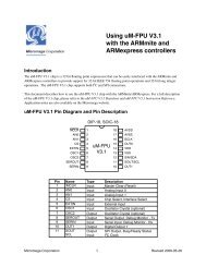
Pin Diagram and Pin Description<br />
CS<br />
SOUT<br />
SCLK/SCK<br />
VSS<br />
1<br />
2<br />
3<br />
4<br />
<strong>uM</strong>-<strong>FPU</strong><br />
8<br />
7<br />
6<br />
5<br />
VDD<br />
TSTIN<br />
TSTOUT<br />
SIN/SDA<br />
Pin Name Type Description<br />
1 CS Input Chip Select<br />
2 SOUT Output SPI Output<br />
Busy/Ready<br />
3 SCLK<br />
SCK<br />
Input SPI Clock<br />
I 2 C Clock<br />
4 VSS Power Ground<br />
5 SIN<br />
SDA<br />
Input<br />
In/Out<br />
SPI Input<br />
I 2 C Data<br />
6 TSTOUT Output Test Output<br />
7 TSTIN Input Test Input<br />
8 VDD Power Supply Voltage<br />
Connecting <strong>the</strong> <strong>uM</strong>-<strong>FPU</strong> to <strong>the</strong> Microchip <strong>PICmicro</strong>® using SPI<br />
The <strong>uM</strong>-<strong>FPU</strong> can be connected using ei<strong>the</strong>r a 2-wire or 3-wire. The 2-wire connection uses a clock signal and a<br />
bidirectional data signal and requires <strong>the</strong> program to change <strong>the</strong> input/output direction of <strong>the</strong> pin as required. The 3-<br />
wire connection uses a clock signal and separate data input and data output signals. The support routines assume a 3-<br />
wire SPI interface. The default settings for <strong>the</strong>se pins are:<br />
Pin PIC16F877 PIC16F628<br />
<strong>FPU</strong>_CLOCK RC3 RB7<br />
<strong>FPU</strong>_DATAIN RC4 RB6<br />
<strong>FPU</strong>_DATAOUT RC5 RB5<br />
The settings of <strong>the</strong>se pins can be changed to suit your application. The default settings for <strong>the</strong> PIC16F877 allow <strong>the</strong><br />
hardware SPI support to be used. By default, <strong>the</strong> <strong>uM</strong>-<strong>FPU</strong> chip is always selected, so <strong>the</strong> <strong>FPU</strong>_CLOCK and<br />
<strong>FPU</strong>_DATAIN/<strong>FPU</strong>_DATAOUT pins should not be used for o<strong>the</strong>r connections as this will likely result in loss of<br />
synchronization between <strong>the</strong> <strong>PICmicro</strong> and <strong>the</strong> <strong>uM</strong>-<strong>FPU</strong> coprocessor.<br />
3-wire SPI Connection<br />
Micromega Corporation 2 <strong>Using</strong> <strong>the</strong> <strong>uM</strong>-<strong>FPU</strong> <strong>with</strong> <strong>the</strong> <strong>PICmicro</strong>
Connecting <strong>the</strong> <strong>uM</strong>-<strong>FPU</strong><br />
2-wire SPI Connection<br />
If a 2-wire SPI interface is used, <strong>the</strong> SOUT and SIN pins should not be connected directly toge<strong>the</strong>r, <strong>the</strong>y<br />
must be connected through a 1K resistor. The microcontroller data pin is connected to <strong>the</strong> SIN pin. See <strong>the</strong> <strong>uM</strong>-<br />
<strong>FPU</strong> datasheet for fur<strong>the</strong>r description of <strong>the</strong> SPI interface.<br />
Connecting <strong>the</strong> <strong>uM</strong>-<strong>FPU</strong> to <strong>the</strong> <strong>PICmicro</strong> using I 2 C<br />
The <strong>uM</strong>-<strong>FPU</strong> <strong>V2</strong> can also be connected using an I 2 C interface. The default slave address for <strong>the</strong> <strong>uM</strong>-<strong>FPU</strong> is<br />
0xC8 (LSB is <strong>the</strong> R/W bit, e.g. 0xC8 for write, 0xC9 for read). See <strong>the</strong> <strong>uM</strong>-<strong>FPU</strong> datasheet for fur<strong>the</strong>r description of<br />
<strong>the</strong> I 2 C interface.<br />
Micromega Corporation 3 <strong>Using</strong> <strong>the</strong> <strong>uM</strong>-<strong>FPU</strong> <strong>with</strong> <strong>the</strong> <strong>PICmicro</strong>
An Introduction to <strong>the</strong> <strong>uM</strong>-<strong>FPU</strong><br />
An Introduction to <strong>the</strong> <strong>uM</strong>-<strong>FPU</strong><br />
The following section provides an introduction to <strong>the</strong> <strong>uM</strong>-<strong>FPU</strong> using <strong>PICmicro</strong> MPASM assembler code for all<br />
examples. For more detailed information about <strong>the</strong> <strong>uM</strong>-<strong>FPU</strong>, please refer to <strong>the</strong> following documents:<br />
<strong>uM</strong>-<strong>FPU</strong> <strong>V2</strong> Datasheet<br />
functional description and hardware specifications<br />
<strong>uM</strong>-<strong>FPU</strong> <strong>V2</strong> Instruction Set<br />
full description of each instruction<br />
<strong>uM</strong>-<strong>FPU</strong> Registers<br />
The <strong>uM</strong>-<strong>FPU</strong> contains sixteen 32-bit registers, numbered 0 through 15, which are used to store floating point or long<br />
integer values. Register 0 is reserved for use as a temporary register and is modified by some of <strong>the</strong> <strong>uM</strong>-<strong>FPU</strong><br />
operations. Registers 1 through 15 are available for general use. Arithmetic operations are defined in terms of an A<br />
register and a B registers. Any of <strong>the</strong> 16 registers can be selected as <strong>the</strong> A or B register.<br />
<strong>uM</strong>-<strong>FPU</strong> Registers<br />
0 32-bit Register<br />
1 32-bit Register<br />
A 2 32-bit Register<br />
3 32-bit Register<br />
4 32-bit Register<br />
B 5 32-bit Register<br />
6 32-bit Register<br />
7 32-bit Register<br />
8 32-bit Register<br />
9 32-bit Register<br />
10 32-bit Register<br />
11 32-bit Register<br />
12 32-bit Register<br />
13 32-bit Register<br />
14 32-bit Register<br />
15 32-bit Register<br />
The FADD instruction adds two floating point values and is defined as A = A + B. To add <strong>the</strong> value in register 5 to<br />
<strong>the</strong> value in register 2, you would do <strong>the</strong> following:<br />
Select register 2 as <strong>the</strong> A register<br />
Select register 5 as <strong>the</strong> B register<br />
Send <strong>the</strong> FADD instruction (A = A + B)<br />
We’ll look at how to send <strong>the</strong>se instructions to <strong>the</strong> <strong>uM</strong>-<strong>FPU</strong> in <strong>the</strong> next section.<br />
Register 0 is a temporary register. If you want to use a value later in your program, store it in one of <strong>the</strong> registers 1<br />
to 15. Several instructions load register 0 <strong>with</strong> a temporary value, and <strong>the</strong>n select register 0 as <strong>the</strong> B register. As you<br />
will see shortly, this is very convenient because o<strong>the</strong>r instructions can use <strong>the</strong> value in register 0 immediately.<br />
Sending Instructions to <strong>the</strong> <strong>uM</strong>-<strong>FPU</strong><br />
Appendix A contains a table that gives a summary of each <strong>uM</strong>-<strong>FPU</strong> instruction, <strong>with</strong> enough information to follow<br />
<strong>the</strong> examples in this document. For a detailed description of each instruction, refer to <strong>the</strong> document entitled <strong>uM</strong>-<strong>FPU</strong><br />
Instruction Set.<br />
Instructions and data are sent to <strong>the</strong> <strong>uM</strong>-<strong>FPU</strong> by loading <strong>the</strong> W register <strong>with</strong> <strong>the</strong> byte value to send and calling <strong>the</strong><br />
fpu_readByte routine. For example:<br />
movlw<br />
call<br />
FADD+5<br />
fpu_sendByte<br />
Micromega Corporation 4 <strong>Using</strong> <strong>the</strong> <strong>uM</strong>-<strong>FPU</strong> <strong>with</strong> <strong>the</strong> <strong>PICmicro</strong>
An Introduction to <strong>the</strong> <strong>uM</strong>-<strong>FPU</strong><br />
All instructions start <strong>with</strong> an opcode that tells <strong>the</strong> <strong>uM</strong>-<strong>FPU</strong> which operation to perform. Some instructions require<br />
additional data or arguments, and some instructions return data. The most common instructions (<strong>the</strong> ones shown in<br />
<strong>the</strong> first half of <strong>the</strong> table in Appendix A), require a single byte for <strong>the</strong> opcode. For example:<br />
movlw<br />
call<br />
SQRT<br />
fpu_sendByte<br />
The instructions in <strong>the</strong> last half of <strong>the</strong> table, are extended opcodes, and require a two byte opcode. The first byte of<br />
extended opcodes is always $FE, defined as XOP. To use an extended opcode, you send <strong>the</strong> XOP byte first,<br />
followed by <strong>the</strong> extended opcode. For example:<br />
movlw<br />
call<br />
movlw<br />
call<br />
XOP<br />
fpu_sendByte<br />
ATAN<br />
fpu_sendByte<br />
Some of <strong>the</strong> most commonly used instructions use <strong>the</strong> lower 4 bits of <strong>the</strong> opcode to select a register. This allows<br />
<strong>the</strong>m to select a register and perform an operation at <strong>the</strong> same time. Opcodes that include a register value are defined<br />
<strong>with</strong> <strong>the</strong> register value equal to 0, so using <strong>the</strong> opcode by itself selects register 0. The following instruction selects<br />
register 0 as <strong>the</strong> B register <strong>the</strong>n calculates A = A + B.<br />
movlw<br />
call<br />
FADD<br />
fpu_sendByte<br />
To select a different register, you simply add <strong>the</strong> register value to <strong>the</strong> opcode. The following instruction selects<br />
register 5 as <strong>the</strong> B register <strong>the</strong>n calculates A = A + B.<br />
movlw<br />
call<br />
FADD+5<br />
fpu_sendByte<br />
Let’s look at a more complete example. Earlier, we described <strong>the</strong> steps required to add <strong>the</strong> value in register 5 to <strong>the</strong><br />
value in register 2. The instruction to perform that operation is as follows:<br />
movlw SELECTA+2 ;select register 2 as <strong>the</strong> A register<br />
call fpu_sendByte<br />
movlw FADD+5 ;select register 5 as <strong>the</strong> B register<br />
call fpu_sendByte ; and calculate A = A + B<br />
It’s a good idea to use constant definitions to provide meaningful names for <strong>the</strong> registers. This makes your program<br />
code easier to read and understand. The same example using constant definitions would be:<br />
#define Total 2 ;total amount (<strong>uM</strong>-<strong>FPU</strong> register)<br />
#define Count 5 ;current count (<strong>uM</strong>-<strong>FPU</strong> register)<br />
movlw SELECTA+Total ;select register Total as <strong>the</strong> A register<br />
call fpu_sendByte<br />
movlw FADD+Count ;select register Count as <strong>the</strong> B register<br />
call fpu_sendByte ; and calculate A = A + B<br />
Selecting <strong>the</strong> A register is such a common occurrence, it was defined as opcode $0x. The definition for SELECTA is<br />
0x00, so SELECTA+Total is <strong>the</strong> same as just using Total by itself. <strong>Using</strong> this shortcut, <strong>the</strong> same example would<br />
now be:<br />
movlw Total ;select register Total as <strong>the</strong> A register<br />
call fpu_sendByte<br />
movlw FADD+Count ;select register Count as <strong>the</strong> B register<br />
call fpu_sendByte ; and calculate A = A + B<br />
Micromega Corporation 5 <strong>Using</strong> <strong>the</strong> <strong>uM</strong>-<strong>FPU</strong> <strong>with</strong> <strong>the</strong> <strong>PICmicro</strong>
Tutorial Example<br />
Tutorial Example<br />
Now that we’ve introduced some of <strong>the</strong> basic concepts of sending instructions to <strong>the</strong> <strong>uM</strong>-<strong>FPU</strong>, let’s go through a<br />
tutorial example to get a better understanding of how it all ties toge<strong>the</strong>r. This example will take a temperature<br />
reading from a DS1620 digital <strong>the</strong>rmometer and convert it to Celsius and Fahrenheit.<br />
Most of <strong>the</strong> data read from devices connected to <strong>the</strong> <strong>PICmicro</strong> will return some type of integer value. In this<br />
example, <strong>the</strong> interface routine for <strong>the</strong> DS1620 reads a 9-bit value and stores it in a two byte (word) variable called<br />
rawTemp. The value returned by <strong>the</strong> DS1620 is <strong>the</strong> temperature in units of 1/2 degrees Celsius. We need to load this<br />
value to <strong>the</strong> <strong>uM</strong>-<strong>FPU</strong> and convert it to floating point. The following instruction is used:<br />
movlw DegC ;select DegC as A register<br />
call fpu_sendByte<br />
movlw LOADWORD ;load rawTemp to register 0,<br />
call fpu_sendByte ; convert to floating point,<br />
movf rawTemp+1, w ; select register 0 as B register<br />
call fpu_sendByte<br />
movf rawTemp, w<br />
call fpu_sendByte<br />
movlw FSET ;degC = register 0 (i.e. set to <strong>the</strong><br />
call fpu_sendByte ; floating point value of rawTemp)<br />
The <strong>uM</strong>-<strong>FPU</strong> register DegreesC now contains <strong>the</strong> value read from <strong>the</strong> DS1620 (converted to floating point). Since<br />
<strong>the</strong> DS1620 works in units of1/2 degree Celsius, DegreesC will be divided by 2 to get <strong>the</strong> degrees in Celsius.<br />
movlw LOADBYTE ;load <strong>the</strong> value 2 to register 0,<br />
call fpu_sendByte ; convert to floating point,<br />
movlw .2 ; select register 0 as B register<br />
call fpu_sendByte<br />
movlw FDIV ;divide DegC by register 0<br />
call fpu_sendByte<br />
To get <strong>the</strong> degrees in Fahrenheit we will use <strong>the</strong> formula F = C * 1.8 + 32. Since 1.8 and 32 are constant values,<br />
<strong>the</strong>y would normally be loaded once in <strong>the</strong> initialization section of your program and used later in <strong>the</strong> main program.<br />
The value 1.8 is loaded by using <strong>the</strong> ATOF (ASCII to float) instruction as follows:<br />
movlw F1_8 ;select F1_8 as A register<br />
call fpu_sendByte<br />
movlw ATOF ;load <strong>the</strong> string 1.8 to <strong>the</strong> <strong>uM</strong>-<strong>FPU</strong><br />
call fpu_sendByte ; (note: string must be zero terminated)<br />
movlw '1' ; convert to floating point,<br />
call fpu_sendByte ; store value in register 0<br />
movlw '.' ; select register 0 as <strong>the</strong> B register<br />
call fpu_sendByte<br />
movlw '8'<br />
call fpu_sendByte<br />
movlw 0<br />
call fpu_sendByte<br />
movlw FSET ;F1_8 = register 0 (i.e. 1.8)<br />
call fpu_sendByte<br />
The value 32 is loaded using <strong>the</strong> LOADBYTE instruction as follows:<br />
movlw F32 ;select F32 as A register<br />
call fpu_sendByte<br />
movlw LOADBYTE ;load <strong>the</strong> byte value 32 to register 0,<br />
Micromega Corporation 6 <strong>Using</strong> <strong>the</strong> <strong>uM</strong>-<strong>FPU</strong> <strong>with</strong> <strong>the</strong> <strong>PICmicro</strong>
Tutorial Example<br />
call fpu_sendByte ; convert to floating point,<br />
movlw .32 ; select register 0 as B register<br />
call fpu_sendByte<br />
movlw FSET ;F32 = register 0 (i.e. 32.0)<br />
call fpu_sendByte<br />
Now using <strong>the</strong>se constant values we calculate <strong>the</strong> degrees in Fahrenheit as follows:<br />
movlw DegF ;select DegF as <strong>the</strong> A register<br />
call fpu_sendByte<br />
movlw FSET+DegC ;set DegF = DegC<br />
call fpu_sendByte<br />
movlw FMUL+F1_8 ;multiply DegF by 1.8<br />
call fpu_sendByte<br />
movlw FADD+F32 ;add 32.0 to DegF<br />
call fpu_sendByte<br />
Now we print <strong>the</strong> results. There are support routines provided for printing floating point numbers. The print_float<br />
routine prints an unformatted floating point value and displays up to eight digits of precision. The print_floatFormat<br />
routine prints a formatted floating point number. We’ll use print_floatFormat to display <strong>the</strong> results. The desired<br />
format is loaded into <strong>the</strong> W register. The tens digit is <strong>the</strong> total number of characters to display, and <strong>the</strong> ones digit is<br />
<strong>the</strong> number of digits after <strong>the</strong> decimal point. The DS1620 has a maximum temperature of 125° Celsius and one<br />
decimal point of precision, so we’ll use a format of 51. Before calling <strong>the</strong> print routine <strong>the</strong> <strong>uM</strong>-<strong>FPU</strong> register is<br />
selected and <strong>the</strong> format variable is set. The following example prints <strong>the</strong> temperature in degrees Fahrenheit.<br />
movlw DegC ;select DegC as A register<br />
call fpu_sendByte<br />
movlw .51 ;set format to 5,1<br />
call print_floatFormat ;print floating point value<br />
Sample code for this tutorial and a wiring diagram for <strong>the</strong> DS1620 are shown at <strong>the</strong> end of this document. The file<br />
demo1.asm is also included <strong>with</strong> <strong>the</strong> support software. There is a second file called demo2.asm that extends this<br />
demo to include minimum and maximum temperature calculations. If you have a DS1620 you can wire up <strong>the</strong><br />
circuit and try out <strong>the</strong> demos.<br />
<strong>uM</strong>-<strong>FPU</strong> Support Software for <strong>the</strong> <strong>PICmicro</strong><br />
A full set of assembler support routines is provided to handle all of <strong>the</strong> communication between <strong>the</strong> <strong>PICmicro</strong> and<br />
<strong>the</strong> <strong>uM</strong>-<strong>FPU</strong>. The routines are designed for use <strong>with</strong> <strong>the</strong> MPLAB IDE using <strong>the</strong> MPASM Assembler and MPLINK<br />
Object Linker. The routines could easily be adapted to o<strong>the</strong>r assemblers. The interface files are as follows:<br />
umfpu.asm<br />
umfpu.inc<br />
fpusw_4.asm<br />
fpusw_20.asm<br />
fpuhw_4.asm<br />
fpuhw_20.asm<br />
delay_4.asm<br />
delay_20.asm<br />
serial.asm<br />
High level routines for each <strong>uM</strong>-<strong>FPU</strong> function<br />
Include file containing definitions for each <strong>uM</strong>-<strong>FPU</strong> instruction opcode<br />
Software SPI interface routine (bit-bang), 4 MHz<br />
Software SPI interface routine (bit-bang), 20 MHz<br />
Hardware SPI interface routine, 4 MHz<br />
Hardware SPI interface routine, 20 MHz<br />
Delay routine, 4 Mhz<br />
Delay routine, 20 Mhz<br />
Serial port routines to print data<br />
MPLAB project files and linker files are provided for each of <strong>the</strong> sample applications. The files can be used directly<br />
to test <strong>the</strong> sample applications, or used as <strong>the</strong> starting point for a new program. Each <strong>uM</strong>-<strong>FPU</strong> support routine is<br />
described below.<br />
Micromega Corporation 7 <strong>Using</strong> <strong>the</strong> <strong>uM</strong>-<strong>FPU</strong> <strong>with</strong> <strong>the</strong> <strong>PICmicro</strong>
Tutorial Example<br />
The following routines are provided in <strong>the</strong> files fpusw_xx and fpuhw_xx.<br />
fpu_reset<br />
To ensure that <strong>the</strong> <strong>PICmicro</strong> and <strong>the</strong> <strong>uM</strong>-<strong>FPU</strong> coprocessor are synchronized, a reset call must be done at <strong>the</strong> start of<br />
every program. The fpu_reset routine resets <strong>the</strong> <strong>uM</strong>-<strong>FPU</strong>, confirms communications, and sets <strong>the</strong> Z flag to 1 if<br />
successful, or 0 if <strong>the</strong> reset failed.<br />
fpu_wait<br />
The <strong>uM</strong>-<strong>FPU</strong> must have completed all calculations and be ready to return <strong>the</strong> data before sending an instruction that<br />
reads data from <strong>the</strong> <strong>uM</strong>-<strong>FPU</strong>. The fpu_wait routine checks <strong>the</strong> status of <strong>the</strong> <strong>uM</strong>-<strong>FPU</strong> and waits until it is ready. The<br />
print routines check <strong>the</strong> ready status, so it isn’t necessary to call fpu_wait before calling a print routine. If your<br />
program reads directly from <strong>the</strong> <strong>uM</strong>-<strong>FPU</strong> using <strong>the</strong> fpu_readByte routine, a call to fpu_wait must be made prior to<br />
sending <strong>the</strong> read instruction. An example of reading a byte value is as follows (<strong>the</strong> fpu_readDelay routine is<br />
described later):<br />
call fpu_wait ;wait for <strong>uM</strong>-<strong>FPU</strong> to be ready<br />
movlw XOP ;read byte of data<br />
call fpu_sendByte<br />
movlw READBYTE<br />
call fpu_sendByte<br />
call fpu_readDelay ;wait for read setup delay<br />
call fpu_readByte ;read <strong>the</strong> byte<br />
The <strong>uM</strong>-<strong>FPU</strong> <strong>V2</strong> has a 32 byte instruction buffer. In most cases, data will be read back before 32 bytes have been<br />
sent to <strong>the</strong> <strong>uM</strong>-<strong>FPU</strong>. If a long calculation is done that requires more than 32 bytes to be sent to <strong>the</strong> <strong>uM</strong>-<strong>FPU</strong>, an<br />
Fpu_Wait call should be made at least every 32 bytes to ensure that <strong>the</strong> instruction buffer doesn’t overflow.<br />
fpu_sendByte<br />
Sends an 8-bit value to <strong>the</strong> <strong>uM</strong>-<strong>FPU</strong>. This routine is used for sending all instructions and data. The byte to send is<br />
loaded in <strong>the</strong> W register before calling <strong>the</strong> routine.<br />
fpu_readByte<br />
Reads an 8-bit value from <strong>the</strong> <strong>uM</strong>-<strong>FPU</strong>. The <strong>uM</strong>-<strong>FPU</strong> must have received a read instruction and be ready to send<br />
data before this routine is called. The byte read from <strong>the</strong> <strong>uM</strong>-<strong>FPU</strong> is returned in <strong>the</strong> W register. The Z flag is also set<br />
according to <strong>the</strong> value of <strong>the</strong> W register.<br />
fpu_readDelay<br />
After a read instruction is sent, and before <strong>the</strong> first fpu_readByte call, a setup delay is required to ensure that <strong>the</strong><br />
<strong>uM</strong>-<strong>FPU</strong> is ready to send data. The fpu_readDelay routine provides <strong>the</strong> required read setup delay. For read<br />
instructions that return multiple bytes, <strong>the</strong> fpu_readDelay call is only required before <strong>the</strong> first byte.<br />
The following routines are provide in <strong>the</strong> file serial.asm.<br />
print_setup<br />
Initializes <strong>the</strong> serial port. This routine must be called in <strong>the</strong> initialization section of <strong>the</strong> program.<br />
print_version<br />
Prints <strong>the</strong> <strong>uM</strong>-<strong>FPU</strong> version string to <strong>the</strong> serial port.<br />
print_float<br />
The value in register A is sent to <strong>the</strong> serial port as a floating point value. Up to eight significant digits will be<br />
displayed if required. Very large or very small numbers are displayed in exponential notation. The length of <strong>the</strong><br />
displayed value is variable and can be from 3 to 12 characters in length. The special cases of NaN (Not a Number),<br />
+Infinity, -Infinity, and -0.0 are handled. Examples of <strong>the</strong> display format are as follows:<br />
Micromega Corporation 8 <strong>Using</strong> <strong>the</strong> <strong>uM</strong>-<strong>FPU</strong> <strong>with</strong> <strong>the</strong> <strong>PICmicro</strong>
Tutorial Example<br />
1.0 NaN 0.0<br />
1.5e20 Infinity -0.0<br />
3.1415927 -Infinity 1.0<br />
-52.333334 -3.5e-5 0.01<br />
print_floatFormat<br />
The value in register A is sent to <strong>the</strong> serial port as a formatted floating point value. The desired format is loaded into<br />
<strong>the</strong> W register. The tens digit specifies <strong>the</strong> total number of characters to display and <strong>the</strong> ones digit specifies <strong>the</strong><br />
number of digits after <strong>the</strong> decimal point. If <strong>the</strong> value is too large for <strong>the</strong> format specified, <strong>the</strong>n asterisks will be<br />
displayed. If <strong>the</strong> number of digits after <strong>the</strong> decimal points is zero, no decimal point will be displayed. Examples of<br />
<strong>the</strong> display format are as follows:<br />
Value in A register format Display format<br />
123.567 61 (6.1) 123.6<br />
123.567 62 (6.2) 123.57<br />
123.567 42 (4.2) *.**<br />
0.9999 20 (2.0) 1<br />
0.9999 31 (3.1) 1.0<br />
print_long<br />
The value in register A is sent to <strong>the</strong> serial port as a signed long integer. The displayed value can range from 1 to 11<br />
characters in length. Examples of <strong>the</strong> display format are as follows:<br />
1<br />
500000<br />
-3598390<br />
print_longFormat<br />
The value in register A is sent to <strong>the</strong> serial port as a formatted long integer. The desired format is loaded into <strong>the</strong> W<br />
register. A value between 0 and 15 specifies <strong>the</strong> width of <strong>the</strong> display field for a signed long integer. The number is<br />
displayed right justified. If 100 is added to <strong>the</strong> format value <strong>the</strong> value is displayed as an unsigned long integer. If <strong>the</strong><br />
value is larger than <strong>the</strong> specified width, asterisks will be displayed. If <strong>the</strong> width is specified as zero, <strong>the</strong> length will<br />
be variable. Examples of <strong>the</strong> display format are as follows:<br />
Value in register A format Display format<br />
-1 10 (signed 10) -1<br />
-1 110 (unsigned 10) 4294967295<br />
-1 4 (signed 4) -1<br />
-1 104 (unsigned 4) ****<br />
0 4 (signed 4) 0<br />
0 0 (unformatted) 0<br />
1000 6 (signed 6) 1000<br />
print_string<br />
A zero terminated string is sent to <strong>the</strong> serial port. The lower part of <strong>the</strong> string address is loaded in <strong>the</strong> W register<br />
before calling print_string. Strings are stored in a special data area called STRINGS that is defined in <strong>the</strong> linker file.<br />
print_byte<br />
Sends <strong>the</strong> 8-bit value in <strong>the</strong> W register to <strong>the</strong> serial port.<br />
print_hex<br />
Sends <strong>the</strong> 8-bit value in <strong>the</strong> W register to <strong>the</strong> serial port as two hexadecimal digits.<br />
print_hexDigit<br />
Sends <strong>the</strong> lower 4-bits of <strong>the</strong> W register to <strong>the</strong> serial port as a hexadecimal digit.<br />
print_crlf<br />
Sends a carriage return and linefeed to <strong>the</strong> serial port.<br />
Micromega Corporation 9 <strong>Using</strong> <strong>the</strong> <strong>uM</strong>-<strong>FPU</strong> <strong>with</strong> <strong>the</strong> <strong>PICmicro</strong>
Tutorial Example<br />
Loading Data Values to <strong>the</strong> <strong>uM</strong>-<strong>FPU</strong><br />
There are several instructions for loading integer values to <strong>the</strong> <strong>uM</strong>-<strong>FPU</strong>. These instructions take an integer value as<br />
an argument, stores <strong>the</strong> value in register 0, converts it to floating point, and selects register 0 as <strong>the</strong> B register. This<br />
allows <strong>the</strong> loaded value to be used immediately by <strong>the</strong> next instruction.<br />
LOADBYTE<br />
Load 8-bit signed integer and convert to floating point<br />
LOADUBYTE<br />
Load 8-bit unsigned integer and convert to floating point<br />
LOADWORD<br />
Load 16-bit signed integer and convert to floating point<br />
LOADUWORD<br />
Load 16-bit unsigned integer and convert to floating point<br />
For example, to calculate Result = Result + 20.0<br />
movlw Result ;select Result as <strong>the</strong> A register<br />
call fpu_sendByte<br />
movlw LOADBYTE ;load <strong>the</strong> byte value 20 to register 0,<br />
call fpu_sendByte ; convert to floating point,<br />
movlw .20 ; select register 0 as B register<br />
call fpu_sendByte<br />
movlw FSET ;Result = register 0 (i.e. 20.0)<br />
call fpu_sendByte<br />
The following instructions take integer value as an argument, stores <strong>the</strong> value in register 0, converts it to a long<br />
integer, and selects register 0 as <strong>the</strong> B register.<br />
LONGBYTE<br />
Load 8-bit signed integer and convert to 32-bit long signed integer<br />
LONGUBYTE<br />
Load 8-bit unsigned integer and convert to 32-bit long unsigned integer<br />
LONGWORD<br />
Load 16-bit signed integer and convert to 32-bit long signed integer<br />
LONGUWORD<br />
Load 16-bit unsigned integer and convert to 32-bit long unsigned integer<br />
For example, to calculate Total = Total / 100<br />
movlw Total ;select Total as <strong>the</strong> A register<br />
call fpu_sendByte<br />
movlw XOP ;load <strong>the</strong> byte value 100 to register 0,<br />
call fpu_sendByte ; convert to floating point,<br />
movlw LONGBYTE ; select register 0 as B register<br />
call fpu_sendByte<br />
movlw .100<br />
call fpu_sendByte<br />
movlw LDIV ;divide Total by register 0<br />
call fpu_sendByte ; (i.e. divide by 100)<br />
There are several instructions for loading commonly used constants. These instructions load <strong>the</strong> constant value to<br />
register 0, and select register 0 as <strong>the</strong> B register.<br />
LOADZERO Load <strong>the</strong> floating point value 0.0 (or long integer 0)<br />
LOADONE Load <strong>the</strong> floating point value 1.0<br />
LOADE Load <strong>the</strong> floating point value of e (2.7182818)<br />
LOADPI Load <strong>the</strong> floating point value of pi (3.1415927)<br />
For example, to set Result = 0.0<br />
movlw Result ;select Result as <strong>the</strong> A register<br />
call fpu_sendByte<br />
movlw XOP ;load 0.0 to register 0,<br />
call fpu_sendByte ; select register 0 as B register<br />
movlw LOADZERO<br />
Micromega Corporation 10 <strong>Using</strong> <strong>the</strong> <strong>uM</strong>-<strong>FPU</strong> <strong>with</strong> <strong>the</strong> <strong>PICmicro</strong>
Tutorial Example<br />
call<br />
fpu_sendByte<br />
movlw FSET ;set Result to <strong>the</strong> value in register 0<br />
call fpu_sendByte ; (i.e. Result = 0.0)<br />
There are two instructions for loading 32-bit floating point values to a specified register. This is one of <strong>the</strong> more<br />
efficient ways to load floating point constants, but requires knowledge of <strong>the</strong> internal representation for floating<br />
point numbers (see Appendix B). A handy utility program called <strong>uM</strong>-<strong>FPU</strong> Converter is available to convert between<br />
floating point strings and 32-bit hexadecimal values.<br />
WRITEA<br />
Write 32-bit floating point value to specified register<br />
WRITAB<br />
Write 32-bit floating point value to specified register<br />
For example, to set Angle = 20.0 (<strong>the</strong> floating point representation for 20.0 is 0x41A00000)<br />
movlw WRITEA+Angle ;select Angle as <strong>the</strong> A register,<br />
call fpu_sendByte<br />
movlw 0x41 ;load 0x41A00000 to A register<br />
call fpu_sendByte ;(32-bit floating point value 20.0)<br />
movlw 0xA0<br />
call fpu_sendByte<br />
movlw 0x00<br />
call fpu_sendByte<br />
movlw 0x00<br />
call fpu_sendByte<br />
There are two instructions for loading 32-bit long integer values to a specified register.<br />
LWRITEA<br />
Write 32-bit long integer value to specified register<br />
LWRITAB<br />
Write 32-bit long integer value to specified register<br />
For example, to set Total = 500000<br />
movlw XOP ;select Total as <strong>the</strong> A register<br />
call fpu_sendByte<br />
movlw LWRITEA+Angle<br />
call fpu_sendByte<br />
movlw 0x00 ;load 0x0007A120 to A register<br />
call fpu_sendByte ;(32-bit long integer value 500000)<br />
movlw 0x07<br />
call fpu_sendByte<br />
movlw 0xA1<br />
call fpu_sendByte<br />
movlw 0x20<br />
call fpu_sendByte<br />
There are two instructions for converting strings to floating point or long integer values.<br />
ATOF<br />
Load ASCII string and convert to floating point<br />
ATOL<br />
Load ASCII string and convert to long integer<br />
For example, to set Angle = 1.5885<br />
movlw Angle ;select Angle as A register<br />
call fpu_sendByte<br />
movlw ATOF ;load <strong>the</strong> string 1.5885 to <strong>the</strong> <strong>uM</strong>-<strong>FPU</strong><br />
call fpu_sendByte ; convert to floating point,<br />
movlw '1' ; store value in register 0<br />
call fpu_sendByte ; select register 0 as <strong>the</strong> B register<br />
movlw '.'<br />
call fpu_sendByte<br />
movlw '5'<br />
Micromega Corporation 11 <strong>Using</strong> <strong>the</strong> <strong>uM</strong>-<strong>FPU</strong> <strong>with</strong> <strong>the</strong> <strong>PICmicro</strong>
Tutorial Example<br />
call fpu_sendByte<br />
movlw '8'<br />
call fpu_sendByte<br />
movlw '8'<br />
call fpu_sendByte<br />
movlw '5'<br />
call fpu_sendByte<br />
movlw 0 ;note: string must be zero terminated<br />
call fpu_sendByte<br />
movlw FSET ;F1_8 = register 0 (i.e. 1.8)<br />
call fpu_sendByte<br />
The fastest operations occur when <strong>the</strong> <strong>uM</strong>-<strong>FPU</strong> registers are already loaded <strong>with</strong> values. In time critical portions of<br />
code floating point constants should be loaded beforehand to maximize <strong>the</strong> processing speed in <strong>the</strong> critical section.<br />
With 15 registers available for storage on <strong>the</strong> <strong>uM</strong>-<strong>FPU</strong>, it is often possible to preload all of <strong>the</strong> required constants. In<br />
non-critical sections of code, data and constants can be loaded as required.<br />
Reading Data Values from <strong>the</strong> <strong>uM</strong>-<strong>FPU</strong><br />
There are two instruction for reading 32-bit floating point values from <strong>the</strong> <strong>uM</strong>-<strong>FPU</strong>.<br />
READFLOAT<br />
Reads a 32-bit floating point value from <strong>the</strong> A register.<br />
FREAD<br />
Reads a 32-bit floating point value from <strong>the</strong> specified register.<br />
The following instructions read <strong>the</strong> floating point value from <strong>the</strong> A register<br />
call fpu_wait<br />
;wait for <strong>uM</strong>-<strong>FPU</strong> to be ready<br />
movlw XOP ;read floating point value A register<br />
call fpu_sendByte<br />
movlw READFLOAT<br />
call fpu_sendByte<br />
call fpu_readDelay ;wait for read setup delay<br />
call fpu_readByte ;read 32-bit value as four bytes<br />
movwf fval+3 ;(most significant byte first)<br />
call fpu_readByte<br />
movwf fval+2<br />
call fpu_readByte<br />
movwf fval+1<br />
call fpu_readByte<br />
movwf fval<br />
There are four instructions for reading integer values from <strong>the</strong> <strong>uM</strong>-<strong>FPU</strong>.<br />
READBYTE<br />
Reads <strong>the</strong> lower 8 bits of <strong>the</strong> value in <strong>the</strong> A register.<br />
READWORD<br />
Reads <strong>the</strong> lower 16 bits of <strong>the</strong> value in <strong>the</strong> A register.<br />
READLONG<br />
Reads a 32-bit long integer value from <strong>the</strong> A register.<br />
LREAD<br />
Reads a 32-bit long integer value from <strong>the</strong> specified register.<br />
The following instructions are used to read a byte value from <strong>the</strong> lower 8 bits of A register<br />
call fpu_wait ;wait for <strong>uM</strong>-<strong>FPU</strong> to be ready<br />
movlw XOP ;read byte of data<br />
call fpu_sendByte<br />
movlw READBYTE<br />
call fpu_sendByte<br />
call fpu_readDelay ;wait for read setup delay<br />
call fpu_readByte ;read <strong>the</strong> byte<br />
Micromega Corporation 12 <strong>Using</strong> <strong>the</strong> <strong>uM</strong>-<strong>FPU</strong> <strong>with</strong> <strong>the</strong> <strong>PICmicro</strong>
Tutorial Example<br />
Comparing and Testing Floating Point Values<br />
A floating point value can be zero, positive, negative, infinite, or Not a Number (which occurs if an invalid<br />
operation is performed on a floating point value). To check <strong>the</strong> status of a floating point number <strong>the</strong> FSTATUS<br />
instruction is sent, and <strong>the</strong> returned byte is stored in <strong>the</strong> status variable. The bit definitions for <strong>the</strong> status<br />
variable are as follows:<br />
bit 0 Zero bit (0 – not zero, 1 – zero)<br />
bit 1 Sign bit (0 – positive, 1 – negative)<br />
bit 2 Not-a-Number (0 – valid number, 1 – NaN)<br />
bit 3 Infinity (0 – not infinite, 1 – infinite)<br />
For example:<br />
#define ZERO 0 ;zero status bit<br />
#define SIGN 1 ;sign status bit<br />
#define NAN 2 ;Not-a-Number status bit<br />
#define INF 3 ;Infinity status bit<br />
call fpu_wait ;wait for <strong>uM</strong>-<strong>FPU</strong> to be ready<br />
movlw FSTATUS ;send FSTATUS instruction<br />
call fpu_sendByte<br />
call fpu_readDelay ;wait for read setup delay<br />
call fpu_readByte ;read status byte and store<br />
movwf status<br />
btfsc status, ZERO ;check status bits<br />
goto zeroValue<br />
btfsc status, SIGN<br />
goto negativeValue<br />
...<br />
negativeValue<br />
...<br />
zeroValue<br />
...<br />
;value is positive<br />
;value is negative<br />
;value is zero<br />
The FCOMPARE instruction is used to compare two floating point values. The status bits are set for <strong>the</strong> results of <strong>the</strong><br />
operation A – B. (The selected A and B registers are not modified). For example:<br />
call fpu_wait ;wait for <strong>uM</strong>-<strong>FPU</strong> to be ready<br />
movlw FCOMPARE ; send FCOMPARE instruction<br />
call fpu_sendByte<br />
call fpu_readDelay ;wait for read setup delay<br />
call fpu_readByte ;read status byte and store<br />
movwf status<br />
btfsc status, ZERO ;check <strong>the</strong> status bits<br />
goto sameAs<br />
btfsc status, SIGN<br />
goto lessThan<br />
... ;A > B<br />
Micromega Corporation 13 <strong>Using</strong> <strong>the</strong> <strong>uM</strong>-<strong>FPU</strong> <strong>with</strong> <strong>the</strong> <strong>PICmicro</strong>
Tutorial Example<br />
lessThan<br />
...<br />
sameAs<br />
...<br />
;A < B"<br />
;A = B<br />
Comparing and Testing Long Integer Values<br />
A long integer value can be zero, positive, or negative. To check <strong>the</strong> status of a long integer number <strong>the</strong> LSTATUS<br />
instruction is sent, and <strong>the</strong> returned byte is stored in <strong>the</strong> status variable. A bit definition is provided for each<br />
status bit in <strong>the</strong> status variable. They are as follows:<br />
bit 0 Zero bit (0 – not zero, 1 – zero)<br />
bit 1 Sign bit (0 – positive, 1 – negative)<br />
For example:<br />
#define ZERO 0 ;zero status bit<br />
#define SIGN 1 ;sign status bit<br />
call fpu_wait ;wait for <strong>uM</strong>-<strong>FPU</strong> to be ready<br />
movlw XOP ;send LSTATUS instruction<br />
call fpu_sendByte<br />
movlw LSTATUS<br />
call fpu_sendByte<br />
call fpu_readDelay ;wait for read setup delay<br />
call fpu_readByte ;read status byte and store<br />
movwf status<br />
btfsc status, ZERO ;check status bits<br />
goto zeroValue<br />
btfsc status, SIGN<br />
goto negativeValue<br />
...<br />
negativeValue<br />
...<br />
zeroValue<br />
...<br />
;value is positive<br />
;value is negative<br />
;value is zero<br />
The LCOMPARE and LUCOMPARE instructions are used to compare two long integer values. The status bits are<br />
set for <strong>the</strong> results of <strong>the</strong> operation A – B (The selected A and B registers are not modified). LCOMPARE does a<br />
signed compare and LUCOMPARE does an unsigned compare. For example, <strong>the</strong> following instructions compare <strong>the</strong><br />
values in registers Value1 and Value2.<br />
call fpu_wait ;wait for <strong>uM</strong>-<strong>FPU</strong> to be ready<br />
movlw Value1 ;select Value1 as A register<br />
call fpu_sendByte<br />
movlw SELECTB+Value2 ;select Value2 as B register<br />
call fpu_sendByte<br />
movlw XOP ;send LCOMPARE instruction<br />
call fpu_sendByte<br />
movlw LCOMPARE<br />
Micromega Corporation 14 <strong>Using</strong> <strong>the</strong> <strong>uM</strong>-<strong>FPU</strong> <strong>with</strong> <strong>the</strong> <strong>PICmicro</strong>
Tutorial Example<br />
call<br />
fpu_sendByte<br />
call fpu_readDelay ;wait for read setup delay<br />
call fpu_readByte ;read status byte and store<br />
movwf status<br />
btfsc status, ZERO ;check <strong>the</strong> status bits<br />
goto sameAs<br />
btfsc status, SIGN<br />
goto lessThan<br />
... ;A > B<br />
lessThan<br />
...<br />
sameAs<br />
...<br />
;A < B"<br />
;A = B<br />
Left and Right Paren<strong>the</strong>sis<br />
Ma<strong>the</strong>matical equations are often expressed <strong>with</strong> paren<strong>the</strong>sis to define <strong>the</strong> order of operations. For example<br />
Y = (X-1) / (X+1). The LEFT and RIGHT paren<strong>the</strong>sis instructions provide a convenient means of allocating<br />
temporary values and changing <strong>the</strong> order of operations.<br />
When a LEFT paren<strong>the</strong>sis instruction is sent, <strong>the</strong> current selection for <strong>the</strong> A register is saved and <strong>the</strong> A register is set<br />
to reference a temporary register. Operations can now be performed as normal <strong>with</strong> <strong>the</strong> temporary register selected<br />
as <strong>the</strong> A register. When a RIGHT paren<strong>the</strong>sis instruction is sent, <strong>the</strong> current value of <strong>the</strong> A register is copied to<br />
register 0, register 0 is selected as <strong>the</strong> B register, and <strong>the</strong> previous A register selection is restored. The value in<br />
register 0 can be used immediately in subsequent operations. Paren<strong>the</strong>sis can be nested for up to five levels. In most<br />
situations, <strong>the</strong> user’s code does not need to select <strong>the</strong> A register inside paren<strong>the</strong>ses since it is selected automatically<br />
by <strong>the</strong> LEFT and RIGHT paren<strong>the</strong>ses instructions.<br />
In <strong>the</strong> following example <strong>the</strong> equation Z = sqrt(X**2 + Y**2) is calculated. Note that <strong>the</strong> original values of X and Y<br />
are retained.<br />
#define Xvalue 1 ;X value (<strong>uM</strong>-<strong>FPU</strong> register 1)<br />
#define Yvalue 2 ;Y value (<strong>uM</strong>-<strong>FPU</strong> register 2)<br />
#define Zvalue 3 ;Z value (<strong>uM</strong>-<strong>FPU</strong> register 3)<br />
movlw Zvalue ;select Zvalue as <strong>the</strong> A register<br />
call fpu_sendByte<br />
movlw FSET+Xvalue ;Zvalue = Xvalue<br />
call fpu_sendByte<br />
movlw FMUL+Xvalue ;Zvalue = Zvalue * Xvalue (i.e. X**2)<br />
call fpu_sendByte<br />
movlw XOP ;save current A register selection,<br />
call fpu_sendByte ; select temporary register as A register (temp)<br />
movlw LEFT<br />
call fpu_sendByte<br />
movlw FSET+Yvalue ;temp = Yvalue<br />
call fpu_sendByte<br />
movlw FMUL+Yvalue ;temp = temp * Yvalue (i.e. Y**2)<br />
call fpu_sendByte<br />
Micromega Corporation 15 <strong>Using</strong> <strong>the</strong> <strong>uM</strong>-<strong>FPU</strong> <strong>with</strong> <strong>the</strong> <strong>PICmicro</strong>
Tutorial Example<br />
movlw XOP ;store temp to register 0,<br />
call fpu_sendByte ; select Zvalue as A<br />
movlw RIGHT ; (previously saved selection)<br />
call fpu_sendByte<br />
movlw FADD ;add register 0 to Zvalue (i.e. X**2 + Y**2)<br />
call fpu_sendByte<br />
movlw SQRT ;take <strong>the</strong> square root of Zvalue<br />
call fpu_sendByte<br />
The following example shows Y = 10 / (X + 1):<br />
movlw Yvalue ;select Yvalue as <strong>the</strong> A register<br />
call fpu_sendByte<br />
movlw LOADBYTE ;load <strong>the</strong> value 10 to register 0,<br />
call fpu_sendByte ; convert to floating point,<br />
movlw .10 ; select register 0 as <strong>the</strong> B register<br />
call fpu_sendByte<br />
movlw FSET ;Yvalue = 10.0<br />
call fpu_sendByte<br />
movlw XOP ;save current A register selection<br />
call fpu_sendByte ; select temporary register as A register (temp)<br />
movlw LEFT<br />
call fpu_sendByte<br />
movlw FSET+Xvalue ;temp = Xvalue<br />
call fpu_sendByte<br />
movlw XOP ;load 1.0 to register 0,<br />
call fpu_sendByte ; select register 0 as <strong>the</strong> B register<br />
movlw LOADONE<br />
call fpu_sendByte<br />
movlw FADD ; temp = temp + 1 (i.e. X+1)<br />
call fpu_sendByte<br />
movlw XOP ;store temp to register 0,<br />
call fpu_sendByte ; select Yvalue as A<br />
movlw RIGHT ; (previously saved selection)<br />
call fpu_sendByte<br />
movlw FDIV ; divide Yvalue by <strong>the</strong> value in register 0<br />
call fpu_sendByte<br />
Micromega Corporation 16 <strong>Using</strong> <strong>the</strong> <strong>uM</strong>-<strong>FPU</strong> <strong>with</strong> <strong>the</strong> <strong>PICmicro</strong>
Alternate Floating Point Format<br />
Alternate Floating Point Format<br />
Several compilers for <strong>the</strong> <strong>PICmicro</strong>® use a slightly modified version of <strong>the</strong> standard IEEE 754 floating point format.<br />
The alternate format is shown below:<br />
Exponent S Mantissa<br />
Exponent S Mantissa<br />
31 24 23 22<br />
0<br />
The <strong>uM</strong>-<strong>FPU</strong> uses <strong>the</strong> standard IEEE 754 format (as described in Appendix B) by default, but it can also support <strong>the</strong><br />
alternate PIC format. To use <strong>the</strong> PIC floating point format, <strong>the</strong> following function call should be made immediately<br />
after a reset:<br />
movlw<br />
call<br />
PICMODE<br />
fpu_sendByte<br />
All internal data on <strong>the</strong> <strong>uM</strong>-<strong>FPU</strong> is still stored in IEEE 754 format, but when <strong>the</strong> <strong>uM</strong>-<strong>FPU</strong> is in PIC mode an<br />
automatic conversion is done by <strong>the</strong> FREAD, FWRITEA, FWRITEB, and READFLOAT instructions so <strong>the</strong><br />
PIC program use floating point data in <strong>the</strong> alternate format. The mode parameter bytes stored in Flash memory can<br />
also be set <strong>with</strong> <strong>the</strong> debug monitor so that PIC floating point format is automatically selected at reset (see <strong>the</strong> <strong>uM</strong>-<br />
<strong>FPU</strong> Datasheet). The IEEEMODE instruction can be used to switch back to standard IEEE 754 floating point mode.<br />
Fur<strong>the</strong>r Information<br />
The following documents are also available:<br />
<strong>uM</strong>-<strong>FPU</strong> <strong>V2</strong> Datasheet<br />
<strong>uM</strong>-<strong>FPU</strong> <strong>V2</strong> Instruction Reference<br />
provides hardware details and specifications<br />
provides detailed descriptions of each instruction<br />
Check <strong>the</strong> Micromega website at www.micromegacorp.com for up-to-date information.<br />
Micromega Corporation 17 <strong>Using</strong> <strong>the</strong> <strong>uM</strong>-<strong>FPU</strong> <strong>with</strong> <strong>the</strong> <strong>PICmicro</strong>
Sample Code<br />
DS1620 Connections for Demo 1<br />
Sample Code for Tutorial (Demo1.asm)<br />
;This program demonstrates how to use <strong>the</strong> <strong>uM</strong>-<strong>FPU</strong> floating point coprocessor<br />
;connected to PIC microcontroller over a 3-wire SPI interface. It takes<br />
;temperature readings from a DS1620 digital <strong>the</strong>rmometer, converts <strong>the</strong>m to<br />
;floating point and displays <strong>the</strong>m in degrees Celsius and degrees Fahrenheit.<br />
list p=16f877 ;list directive to define processor<br />
#include <br />
;processor specific variable definitions<br />
__CONFIG _CP_OFF & _WDT_OFF & _BODEN_ON & _PWRTE_ON & _HS_OSC<br />
& _WRT_ENABLE_ON & _LVP_OFF & _DEBUG_OFF & _CPD_OFF<br />
#include umfpu.inc<br />
;<strong>uM</strong>-<strong>FPU</strong> definitions<br />
extern<br />
extern<br />
extern<br />
delay_ms<br />
print_setup, print_byte, print_crlf, print_string<br />
print_version, print_floatFormat, print_hex<br />
;-------------------- <strong>uM</strong>-<strong>FPU</strong> register definitions -----------------------------<br />
#define DegC 1 ;degrees Celsius<br />
#define DegF 2 ;degrees Fahrenheit<br />
#define F1_8 3 ;constant 1.8<br />
#define F32 4 ;constant 32.0<br />
;-------------------- variable definitions ------------------------------------<br />
udata<br />
#define DS_RST PORTA, 0 ;DS1620 reset/enable<br />
#define DS_CLK PORTA, 1 ;DS1620 clock<br />
#define DS_DATA PORTA, 2 ;DS1620 data<br />
#define DS_DATA_DIR TRISA, 2 ;direction bit<br />
dataBits res 1 ;data bits<br />
bitCount res 1 ;bit count<br />
delayCnt res 1 ;counter for main loop delay<br />
rawTemp res 2 ;raw temperature<br />
;-------------------- string definitions --------------------------------------<br />
; lower byte of stringTable address must be 00<br />
; stringTable can have up to 255 bytes of data<br />
; all strings must be zero terminated<br />
STRINGS code<br />
global stringTable<br />
Micromega Corporation 18 <strong>Using</strong> <strong>the</strong> <strong>uM</strong>-<strong>FPU</strong> <strong>with</strong> <strong>the</strong> <strong>PICmicro</strong>
Sample Code<br />
stringTable<br />
addwf PCL,f ;computed goto for strings<br />
start1Message<br />
dt 0x0D, 0x0A<br />
dt 0x0D, 0x0A, "Demo1 - ", 0<br />
start2Message<br />
dt 0x0D, 0x0A, "-------------------", 0x0D, 0x0A, 0<br />
errorMessage<br />
dt "<strong>uM</strong>-<strong>FPU</strong> not detected", 0<br />
rawString<br />
dt 0x0D, 0x0A, "Raw Temp: ", 0<br />
degCString<br />
dt ", Degrees C:", 0<br />
degFString<br />
dt ", Degrees F:", 0<br />
;-------------------- reset and interrupt vector ------------------------------<br />
STARTUP code<br />
nop ;reset vector<br />
goto reset<br />
nop<br />
nop<br />
goto isr ;interrupt vector<br />
;-------------------- interrupt service routine -------------------------------<br />
PROG<br />
isr<br />
retfie<br />
code<br />
;(no interrupts used)<br />
;==============================================================================<br />
;-------------------- initialization ------------------------------------------<br />
;==============================================================================<br />
reset<br />
call print_setup ;initialize <strong>the</strong> serial port<br />
movlw LOW start1Message ;display startup string<br />
call print_string<br />
; reset <strong>the</strong> <strong>uM</strong>-<strong>FPU</strong> and display version<br />
;-------------------------------------<br />
call fpu_reset ;reset <strong>the</strong> <strong>uM</strong>-<strong>FPU</strong><br />
btfsc STATUS, Z ;check status<br />
goto reset2<br />
movlw LOW errorMessage ;print error message if reset failed<br />
call print_string<br />
goto done<br />
reset2<br />
call print_version ;print <strong>uM</strong>-<strong>FPU</strong> version number<br />
movlw LOW start2Message ;display underline<br />
call print_string<br />
call init_DS1620 ;initizlize <strong>the</strong> DS1620<br />
; load constant 1.8<br />
;------------------<br />
movlw F1_8 ;select F1_8 as A register<br />
call fpu_sendByte<br />
movlw ATOF ;load <strong>the</strong> string 1.8 to <strong>the</strong> <strong>uM</strong>-<strong>FPU</strong><br />
Micromega Corporation 19 <strong>Using</strong> <strong>the</strong> <strong>uM</strong>-<strong>FPU</strong> <strong>with</strong> <strong>the</strong> <strong>PICmicro</strong>
Sample Code<br />
call fpu_sendByte ; (note: string must be zero terminated)<br />
movlw '1' ; convert to floating point,<br />
call fpu_sendByte ; store value in register 0<br />
movlw '.' ; select register 0 as <strong>the</strong> B register<br />
call fpu_sendByte<br />
movlw '8'<br />
call fpu_sendByte<br />
movlw 0<br />
call fpu_sendByte<br />
movlw FSET ;F1_8 = register 0 (i.e. 1.8)<br />
call fpu_sendByte<br />
; load constant 32.0<br />
;-------------------<br />
movlw F32 ;select F32 as A register<br />
call fpu_sendByte<br />
movlw LOADBYTE ;load <strong>the</strong> byte value 32 to register 0,<br />
call fpu_sendByte ; convert to floating point,<br />
movlw .32 ; select register 0 as B register<br />
call fpu_sendByte<br />
movlw FSET ;F32 = register 0 (i.e. 32.0)<br />
call fpu_sendByte<br />
;==============================================================================<br />
;-------------------- main routine -------------------------------------------<br />
;==============================================================================<br />
main<br />
;get temperature reading from DS1620<br />
;------------------------------------<br />
call read_temperature ;read temperature<br />
movlw LOW rawString ;display string<br />
call print_string<br />
movf rawTemp+1, w ;display raw Temperature as hex<br />
call print_hex<br />
movf rawTemp, w<br />
call print_hex<br />
;load rawTemp to <strong>uM</strong>-<strong>FPU</strong>, convert to floating point, and store in register<br />
;--------------------------------------------------------------------------<br />
movlw DegC ;select DegC as A register<br />
call fpu_sendByte<br />
movlw LOADWORD ;load rawTemp to register 0,<br />
call fpu_sendByte ; convert to floating point,<br />
movf rawTemp+1, w ; select register 0 as B register<br />
call fpu_sendByte<br />
movf rawTemp, w<br />
call fpu_sendByte<br />
movlw FSET ;degC = register 0 (i.e. set to <strong>the</strong><br />
call fpu_sendByte ; floating point value of rawTemp)<br />
;divide <strong>the</strong> raw value by 2 to get degrees Celsius<br />
;-------------------------------------------------<br />
movlw LOADBYTE ;load <strong>the</strong> value 2 to register 0,<br />
call fpu_sendByte ; convert to floating point,<br />
movlw .2 ; select register 0 as B register<br />
call fpu_sendByte<br />
movlw FDIV ;divide DegC by register 0<br />
call fpu_sendByte ; (i.e. divide by 2)<br />
;DegF = DegC * 1.8 + 32<br />
;----------------------<br />
movlw DegF ;select DegF as <strong>the</strong> A register<br />
Micromega Corporation 20 <strong>Using</strong> <strong>the</strong> <strong>uM</strong>-<strong>FPU</strong> <strong>with</strong> <strong>the</strong> <strong>PICmicro</strong>
Sample Code<br />
call fpu_sendByte<br />
movlw FSET+DegC ;set DegF = DegC<br />
call fpu_sendByte<br />
movlw FMUL+F1_8 ;multiply DegF by 1.8<br />
call fpu_sendByte<br />
movlw FADD+F32 ;add 32.0 to DegF<br />
call fpu_sendByte<br />
;display degrees Celsius<br />
;-----------------------<br />
movlw LOW degCString ;display text string<br />
call print_string<br />
movlw DegC ;select DegC as A register<br />
call fpu_sendByte<br />
movlw .51 ;set format to 5,1<br />
call print_floatFormat ;print floating point value<br />
;display degrees Fahrenheit<br />
;--------------------------<br />
movlw LOW degFString ;display text string<br />
call print_string<br />
movlw DegF ;select DegF as A register<br />
call fpu_sendByte<br />
movlw .51 ;set format to 5,1<br />
call print_floatFormat ;print floating point value<br />
;delay for 2 seconds and repeat main loop<br />
;-----------------------------------------<br />
movlw 8 ;8 x 250 msec = 2 seconds<br />
movwf delayCnt<br />
pause<br />
movlw .250 ;delay for 1 second<br />
call delay_ms<br />
decfsz delayCnt, f ;loop for all bits<br />
goto pause<br />
goto main ;repeat main loop<br />
;-------------------- init_DS1620 --------------------------------------------<br />
; initialize DS1620<br />
;------------------------------------------------------------------------------<br />
init_DS1620<br />
bcf DS_RST ;initialize pins<br />
bsf DS_CLK<br />
bankselTRISA<br />
movlw 0x06 ;congiure A0-A3 for digitial I/O<br />
movwf ADCON1<br />
movlw 0xF8 ;configure A0-A2 as outputs<br />
movwf TRISA<br />
banksel PORTA<br />
movlw .100 ;delay<br />
call delay_ms<br />
bsf DS_RST ;configure for CPU control<br />
movlw 0x0C<br />
call write_DS1620<br />
movlw 0x02<br />
call write_DS1620<br />
Micromega Corporation 21 <strong>Using</strong> <strong>the</strong> <strong>uM</strong>-<strong>FPU</strong> <strong>with</strong> <strong>the</strong> <strong>PICmicro</strong>
Sample Code<br />
bcf<br />
DS_RST<br />
movlw .100 ;delay<br />
call delay_ms<br />
bsf DS_RST ;start temperature conversions<br />
movlw 0xEE<br />
call write_DS1620<br />
bcf DS_RST<br />
movlw .250 ;delay 1 second<br />
call delay_ms<br />
movlw .250<br />
call delay_ms<br />
movlw .250<br />
call delay_ms<br />
movlw .250<br />
call delay_ms<br />
return<br />
done<br />
goto done ;error exit<br />
;-------------------- write_DS1620 -------------------------------------------<br />
; write DS1620 command<br />
;------------------------------------------------------------------------------<br />
write_DS1620<br />
movwf dataBits ;save <strong>the</strong> byte to send<br />
movlw .8 ;get number of bits to send<br />
movwf bitCount<br />
write2<br />
bcf DS_DATA ;set data output LOW<br />
rrf dataBits, f ;get next data bit<br />
btfsc STATUS, C ;if next bit is 1, set data output HIGH<br />
bsf DS_DATA<br />
bcf DS_CLK ;pulse <strong>the</strong> clock<br />
bsf DS_CLK<br />
decfsz bitCount, f ;loop for all bits<br />
goto write2<br />
return<br />
;-------------------- read_temperature ---------------------------------------<br />
; read temperature value from DS1620 and store in rawTemp<br />
;------------------------------------------------------------------------------<br />
read_temperature<br />
bsf DS_RST ;enable DS1620<br />
movlw 0xAA ;send read temperature command<br />
call write_DS1620<br />
banksel TRISA<br />
bsf DS_DATA_DIR ;configure DS_DATA as input<br />
banksel PORTA<br />
movlw .8 ;get number of bits to receive<br />
movwf bitCount<br />
read2<br />
bcf DS_CLK ;set clock LOW<br />
bcf STATUS, C ;set carry to zero<br />
Micromega Corporation 22 <strong>Using</strong> <strong>the</strong> <strong>uM</strong>-<strong>FPU</strong> <strong>with</strong> <strong>the</strong> <strong>PICmicro</strong>
Sample Code<br />
btfsc DS_DATA ;check data input<br />
bsf STATUS, C ;if HIGH, set carry to one<br />
bsf DS_CLK ;set clock HIGH<br />
rrf rawTemp, f ;store next data bit<br />
decfsz bitCount, f ;loop for all bits<br />
goto read2<br />
clrw<br />
;clear high bits<br />
btfsc DS_DATA ;check data input<br />
movlw 0xFF ;if HIGH, set high bits<br />
bsf DS_CLK ;set clock HIGH<br />
movwf rawTemp+1 ;store high bits<br />
bsf DS_CLK ;set clock HIGH<br />
banksel TRISA<br />
bcf DS_DATA_DIR ;configure DS_DATA as output<br />
banksel PORTA<br />
bcf<br />
DS_RST ;disable DS1620<br />
return<br />
end<br />
Micromega Corporation 23 <strong>Using</strong> <strong>the</strong> <strong>uM</strong>-<strong>FPU</strong> <strong>with</strong> <strong>the</strong> <strong>PICmicro</strong>
Appendix A<br />
<strong>uM</strong>-<strong>FPU</strong> <strong>V2</strong> Instruction Summary<br />
Opcode Name<br />
Data<br />
Type<br />
Opcode Arguments Returns B Reg Description<br />
SELECTA 0x Select A register<br />
SELECTB 1x x Select B register<br />
FWRITEA Float 2x yyyy zzzz Write register and select A<br />
FWRITEB Float 3x yyyy zzzz x Write register and select B<br />
FREAD Float 4x yyyy zzzz Read register<br />
FSET/LSET Ei<strong>the</strong>r 5x A = B<br />
FADD Float 6x x A = A + B<br />
FSUB Float 7x x A = A - B<br />
FMUL Float 8x x A = A * B<br />
FDIV Float 9x x A = A / B<br />
LADD Long Ax x A = A + B<br />
LSUB Long Bx x A = A -B<br />
LMUL Long Cx x A = A * B<br />
LDIV Long Dx x<br />
A = A / B<br />
Remainder stored in register 0<br />
SQRT Float E0 A = sqrt(A)<br />
LOG Float E1 A = ln(A)<br />
LOG10 Float E2 A = log(A)<br />
EXP Float E3 A = e ** A<br />
EXP10 Float E4 A = 10 ** A<br />
SIN Float E5 A = sin(A) radians<br />
COS Float E6 A = cos(A) radians<br />
TAN Float E7 A = tan(A) radians<br />
FLOOR Float E8 A = nearest integer = A<br />
ROUND Float EA A = nearest integer to A<br />
NEGATE Float EB A = -A<br />
ABS Float EC A = |A|<br />
INVERSE Float ED A = 1 / A<br />
DEGREES Float EE<br />
Convert radians to degrees<br />
A = A / (PI / 180)<br />
RADIANS Float EF<br />
Convert degrees to radians<br />
A = A * (PI / 180)<br />
SYNC F0 5C Synchronization<br />
FLOAT Long F1 0<br />
Copy A to register 0<br />
Convert long to float<br />
FIX Float F2 0<br />
Copy A to register 0<br />
Convert float to long<br />
FCOMPARE Float F3 ss<br />
Compare A and B<br />
(floating point)<br />
LOADBYTE Float F4 bb 0<br />
Write signed byte to register 0<br />
Convert to float<br />
LOADUBYTE Float F5 bb 0<br />
Write unsigned byte to register 0<br />
Convert to float<br />
LOADWORD Float F6 wwww 0<br />
Write signed word to register 0<br />
Convert to float<br />
LOADUWORD Float F7 wwww 0<br />
Write unsigned word to register 0<br />
Convert to float<br />
READSTR F8 aa … 00<br />
Read zero terminated string from<br />
string buffer<br />
Micromega Corporation 24 Revised 2005-01-11
Appendix A - Instruction Summary<br />
ATOF Float F9 aa … 00 0<br />
Convert ASCII to float<br />
Store in A<br />
FTOA Float FA ff<br />
Convert float to ASCII<br />
Store in string buffer<br />
ATOL Long FB aa … 00 0<br />
Convert ASCII to long<br />
Store in A<br />
LTOA Long FC ff<br />
Convert long to ASCII<br />
Store in string buffer<br />
FSTATUS Float FD ss Get floating point status of A<br />
XOP<br />
FE<br />
Extended opcode prefix (extended<br />
opcodes are listed below)<br />
NOP FF No Operation<br />
FE0n<br />
User defined functions 0-15<br />
FUNCTION<br />
FE1n<br />
User defined functions 16-31<br />
0<br />
FE2n<br />
User defined functions 32-47<br />
FE3n<br />
User defined functions 48-63<br />
IF_FSTATUSA Float FE80 ss<br />
Execute user function code if<br />
FSTATUSA conditions match<br />
IF_FSTATUSB Float FE81 ss<br />
Execute user function code if<br />
FSTATUSB conditions match<br />
IF_FCOMPARE Float FE82 ss<br />
Execute user function code if<br />
FCOMPARE conditions match<br />
IF_LSTATUSA Long FE83 ss<br />
Execute user function code if<br />
LSTATUSA conditions match<br />
IF_LSTATUSB Long FE84 ss<br />
Execute user function code if<br />
LSTATUSB conditions match<br />
IF_LCOMPARE Long FE85 ss<br />
Execute user function code if<br />
LCOMPARE conditions match<br />
IF_LUCOMPARE Long FE86 ss<br />
Execute user function code if<br />
LUCOMPARE conditions match<br />
IF_LTST Long FE87 ss<br />
Execute user function code if<br />
LTST conditions match<br />
TABLE Ei<strong>the</strong>r FE88 Table Lookup (user function)<br />
POLY Float FE89<br />
Calculate n th degree polynomial<br />
(user function)<br />
READBYTE Long FE90 bb Get lower 8 bits of register A<br />
READWORD Long FE91 bb Get lower 16 bits of register A<br />
READLONG Long FE92 bb Get long integer value of register A<br />
READFLOAT Float FE93 bb Get floating point value of register A<br />
LINCA Long FE94 A = A + 1<br />
LINCB Long FE95 B = B + 1<br />
LDECA Long FE96 A = A - 1<br />
LDECB Long FE97 B = B - 1<br />
LAND Long FE98 A = A AND B<br />
LOR Long FE99 A = A OR B<br />
LXOR Long FE9A A = A XOR B<br />
LNOT Long FE9B A = NOT A<br />
LTST Long FE9C ss Get <strong>the</strong> status of A AND B<br />
LSHIFT Long FE9D A = A shifted by B bit positions<br />
LWRITEA Long FEAx yyyy zzzz Write register and select A<br />
LWRITEB Long FEBx yyyy zzzz x Write register and select B<br />
LREAD Long FECx yyyy zzzz Read register<br />
LUDIV Long FEDx x<br />
A = A / B (unsigned long)<br />
Remainder stored in register 0<br />
POWER Float FEE0 A = A ** B<br />
ROOT Float FEE1 A = <strong>the</strong> Bth root of A<br />
MIN Float FEE2 A = minimum of A and B<br />
MAX Float FEE3 A = maximum of A and B<br />
Micromega Corporation 25 <strong>Using</strong> <strong>the</strong> <strong>uM</strong>-<strong>FPU</strong> <strong>with</strong> <strong>the</strong> <strong>PICmicro</strong>
Appendix A - Instruction Summary<br />
FRACTION Float FEE4 0<br />
Load Register 0 <strong>with</strong> <strong>the</strong> fractional<br />
part of A<br />
ASIN Float FEE5 A = asin(A) radians<br />
ACOS Float FEE6 A = acos(A) radians<br />
ATAN Float FEE7 A = atan(A) radians<br />
ATAN2 Float FEE8 A = atan(A/B)<br />
LCOMPARE Long FEE9 ss<br />
Compare A and B<br />
(signed long integer)<br />
LUCOMPARE Long FEEA ss<br />
Compare A and B<br />
(unsigned long integer)<br />
LSTATUS Long FEEB ss Get long status of A<br />
LNEGATE Long FEEC A = -A<br />
LABS Long FEED A = |A|<br />
LEFT FEEE Right paren<strong>the</strong>sis<br />
RIGHT FEEF 0 Left paren<strong>the</strong>sis<br />
LOADZERO Float FEF0 0 Load Register 0 <strong>with</strong> Zero<br />
LOADONE Float FEF1 0 Load Register 0 <strong>with</strong> 1.0<br />
LOADE Float FEF2 0 Load Register 0 <strong>with</strong> e<br />
LOADPI Float FEF3 0 Load Register 0<strong>with</strong> pi<br />
LONGBYTE Long FEF4 bb 0<br />
Write signed byte to register 0<br />
Convert to long<br />
LONGUBYTE Long FEF5 bb 0<br />
Write unsigned byte to register 0<br />
Convert to long<br />
LONGWORD Long FEF6 wwww 0<br />
Write signed word to register 0<br />
Convert to long<br />
LONGUWORD Long FEF7 wwww 0<br />
Write unsigned word to register 0<br />
Convert to long<br />
IEEEMODE FEF8 Set IEEE mode (default)<br />
PICMODE FEF9 Set PIC mode<br />
CHECKSUM FEFA 0 Calculate checksum for <strong>uM</strong>-<strong>FPU</strong> code<br />
BREAK FEFB Debug breakpoint<br />
TRACEOFF FEFC Turn debug trace off<br />
TRACEON FEFD Turn debug trace on<br />
TRACESTR FEFE aa … 00 Send debug string to trace buffer<br />
VERSION FEFF Copy version string to string buffer<br />
Notes:<br />
Data Type data type required by opcode<br />
Opcode hexadecimal opcode value<br />
Arguments additional data required by opcode<br />
Returns data returned by opcode<br />
B Reg<br />
value of B register after opcode executes<br />
x register number (0-15)<br />
n function number (0-63)<br />
yyyy<br />
most significant 16 bits of 32-bit value<br />
zzzz<br />
least significant 16 bits of 32-bit value<br />
ss<br />
status byte<br />
bb<br />
8-bit value<br />
wwww<br />
16-bit value<br />
aa … 00 zero terminated ASCII string<br />
Micromega Corporation 26 <strong>Using</strong> <strong>the</strong> <strong>uM</strong>-<strong>FPU</strong> <strong>with</strong> <strong>the</strong> <strong>PICmicro</strong>
Appendix B<br />
Floating Point Numbers<br />
Floating point numbers can store both very large and very small values by “floating” <strong>the</strong> window of precision to<br />
fit <strong>the</strong> scale of <strong>the</strong> number. Fixed point numbers can’t handle very large or very small numbers and are prone to<br />
loss of precision when numbers are divided. The representation of floating point numbers used by <strong>the</strong> <strong>uM</strong>-<strong>FPU</strong><br />
is defined by <strong>the</strong> IEEE 754 standard.<br />
The range of numbers that can be handled by <strong>the</strong> <strong>uM</strong>-<strong>FPU</strong> is approximately ± 10 38.53 .<br />
.<br />
IEEE 754 32-bit Floating Point Representation<br />
IEEE floating point numbers have three components: <strong>the</strong> sign, <strong>the</strong> exponent, and <strong>the</strong> mantissa. The sign<br />
indicates whe<strong>the</strong>r <strong>the</strong> number is positive or negative. The exponent has an implied base of two. The mantissa is<br />
composed of <strong>the</strong> fraction.<br />
The 32-bit IEEE 754 representation is as follows:<br />
S<br />
Exponent<br />
Mantissa<br />
31 30 23 22 0<br />
Sign Bit (S)<br />
The sign bit is 0 for a positive number and 1 for a negative number.<br />
Exponent<br />
The exponent field is an 8-bit field that stores <strong>the</strong> value of <strong>the</strong> exponent <strong>with</strong> a bias of 127 that allows<br />
it to represent both positive and negative exponents. For example, if <strong>the</strong> exponent field is 128, it<br />
represents an exponent of one (128 – 127 = 1). An exponent field of all zeroes is used for denormalized<br />
numbers and an exponent field of all ones is used for <strong>the</strong> special numbers +infinity, -infinity and Nota-Number<br />
(described below).<br />
Mantissa<br />
Special Values<br />
The mantissa is a 23-bit field that stores <strong>the</strong> precision bits of <strong>the</strong> number. For normalized numbers<br />
<strong>the</strong>re is an implied leading bit equal to one.<br />
Zero<br />
A zero value is represented by an exponent of zero and a mantissa of zero. Note that +0 and –0<br />
are distinct values although <strong>the</strong>y compare as equal.<br />
Denormalized<br />
If an exponent is all zeros, but <strong>the</strong> mantissa is non-zero <strong>the</strong> value is a denormalized number.<br />
Denormalized numbers are used to represent very small numbers and provide for an extended<br />
Micromega Corporation 27 Revised 2005-01-11
Appendix B – Floating Point Numbers<br />
range and a graceful transition towards zero on underflows. Note: The <strong>uM</strong>-<strong>FPU</strong> does not support<br />
operations using denormalized numbers.<br />
Infinity<br />
The values +infinity and –infinity are denoted <strong>with</strong> an exponent of all ones and a fraction of all<br />
zeroes. The sign bit distinguishes between +infinity and –infinity. This allows operations to<br />
continue past an overflow. A nonzero number divided by zero will result in an infinity value.<br />
Not A Number (NaN)<br />
The value NaN is used to represent a value that does not represent a real number. An operation<br />
such as zero divided by zero will result in a value of NaN. The NaN value will flow through any<br />
ma<strong>the</strong>matical operation. Note: The <strong>uM</strong>-<strong>FPU</strong> initializes all of its registers to NaN at reset, <strong>the</strong>refore<br />
any operation that uses a register that has not been previously set <strong>with</strong> a value will produce a result<br />
of NaN.<br />
Some examples of IEEE 754 32-bit floating point values displayed as four byte values are as follows:<br />
0x00, 0x00, 0x00, 0x00 ;0.0<br />
0x3D, 0xCC, 0xCC, 0xCD ;0.1<br />
0x3F, 0x00, 0x00, 0x00 ;0.5<br />
0x3F, 0x40, 0x00, 0x00 ;0.75<br />
0x3F, 0x7F, 0xF9, 0x72 ;0.9999<br />
0x3F, 0x80, 0x00, 0x00 ;1.0<br />
0x40, 0x00, 0x00, 0x00 ;2.0<br />
0x40, 0x2D, 0xF8, 0x54 ;2.7182818 (e)<br />
0x40, 0x49, 0x0F, 0xDB ;3.1415927 (pi)<br />
0x41, 0x20, 0x00, 0x00 ;10.0<br />
0x42, 0xC8, 0x00, 0x00 ;100.0<br />
0x44, 0x7A, 0x00, 0x00 ;1000.0<br />
0x44, 0x9A, 0x52, 0x2B ;1234.5678<br />
0x49, 0x74, 0x24, 0x00 ;1000000.0<br />
0x80, 0x00, 0x00, 0x00 ;-0.0<br />
0xBF, 0x80, 0x00, 0x00 ;-1.0<br />
0xC1, 0x20, 0x00, 0x00 ;-10.0<br />
0xC2, 0xC8, 0x00, 0x00 ;-100.0<br />
0x7F, 0xC0, 0x00, 0x00 ;NaN (Not-a-Number)<br />
0x7F, 0x80, 0x00, 0x00 ;+inf<br />
0xFF, 0x80, 0x00, 0x00 ;-inf<br />
Micromega Corporation 28 <strong>Using</strong> <strong>the</strong> <strong>uM</strong>-<strong>FPU</strong> <strong>with</strong> <strong>the</strong> <strong>PICmicro</strong>