Split System Heat Pump
Fedder HEAT PUMP - Betz Heating and Plumbing
Fedder HEAT PUMP - Betz Heating and Plumbing
- No tags were found...

Create successful ePaper yourself
Turn your PDF publications into a flip-book with our unique Google optimized e-Paper software.
Residential & Light Commercial HVAC<br />
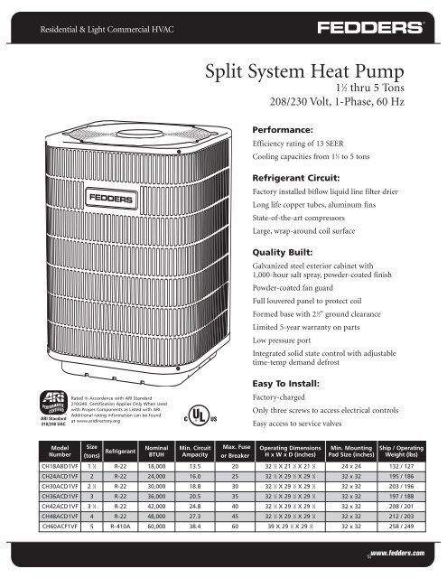
<strong>Split</strong> <strong>System</strong> <strong>Heat</strong> <strong>Pump</strong><br />
1 1 ⁄2 thru 5 Tons<br />
208/230 Volt, 1-Phase, 60 Hz<br />
Performance:<br />
Efficiency rating of 13 SEER<br />
Cooling capacities from 1 1 ⁄2 to 5 tons<br />
Refrigerant Circuit:<br />
Factory installed biflow liquid line filter drier<br />
Long life copper tubes, aluminum fins<br />
State-of-the-art compressors<br />
Large, wrap-around coil surface<br />
Quality Built:<br />
Galvanized steel exterior cabinet with<br />
1,000-hour salt spray, powder-coated finish<br />
Powder-coated fan guard<br />
Full louvered panel to protect coil<br />
Formed base with 2 1 ⁄2" ground clearance<br />
Limited 5-year warranty on parts<br />
Low pressure port<br />
Integrated solid state control with adjustable<br />
time-temp demand defrost<br />
Rated in Accordance with ARI Standard<br />
210/240. Certification Applies Only When Used<br />
with Proper Components as Listed with ARI.<br />
Additional rating information can be found<br />
at www.aridirectory.org<br />
Easy To Install:<br />
Factory-charged<br />
Only three screws to access electrical controls<br />
Easy access to service valves<br />
Model<br />
Number<br />
Size<br />
(tons)<br />
Refrigerant<br />
Nominal<br />
BTUH<br />
Min. Circuit<br />
Ampacity<br />
2Max. Fuse<br />
or Breaker<br />
Operating Dimensions<br />
H x W x D (inches)<br />
Min. Mounting<br />
Pad Size (inches)<br />
Ship / Operating<br />
Weight (lbs)<br />
CH18ABD1VF 1 1 ⁄2 R-22 18,000 13.5 20 32 1 ⁄2 X 21 1 ⁄2 X 21 1 ⁄2 24 x 24 132 / 127<br />
CH24ACD1VF 2 R-22 24,000 16.0 25 32 1 ⁄2 X 29 1 ⁄2 X 29 1 ⁄2 32 x 32 195 / 186<br />
CH30ACD1VF 2 1 ⁄2 R-22 30,000 18.8 30 32 1 ⁄2 X 29 1 ⁄2 X 29 1 ⁄2 32 x 32 203 / 196<br />
CH36ACD1VF 3 R-22 36,000 20.5 35 32 1 ⁄2 X 29 1 ⁄2 X 29 1 ⁄2 32 x 32 197 / 188<br />
CH42ACD1VF 3 1 ⁄2 R-22 42,000 24.8 40 32 1 ⁄2 X 29 1 ⁄2 X 29 1 ⁄2 32 x 32 208 / 201<br />
CH48ACD1VF 4 R-22 48,000 27.3 45 32 1 ⁄2 X 29 1 ⁄2 X 29 1 ⁄2 32 x 32 212 / 203<br />
CH60ACF1VF 5 R-410A 60,000 38.4 60 39 X 29 1 ⁄2 X 29 1 ⁄2 32 x 32 258 / 249
Product Specifications<br />
PHYSICAL DATA<br />
MODEL SIZE 18 24 30 36 42 48 60<br />
PERFORMANCE DATA<br />
NOMINAL CAPACITY (BTUH) 18,000 24,000 30,000 36,000 42,000 48,000 60,000<br />
SEER 1 13 13 13 13 13 13 13<br />
FAN DATA<br />
FAN MOTOR TYPE PSC PSC PSC PSC PSC PSC PSC<br />
HP 1/6 1/3 1/3 1/3 1/3 1/3 1/3<br />
DIAMETER 18" 22" 22" 22" 22" 22" 24"<br />
BLADE 3 3 3 3 3 3 3<br />
RPM 1,050 1,050 1,050 1,050 1,050 1,050 950<br />
CFM 1,800 3,400 3,400 3,400 3,400 3,400 4,000<br />
OUTDOOR COIL<br />
TYPE<br />
Enhanced Aluminum Plate Fin / Rifled Copper Tube<br />
COIL FACE AREA (ft 2 ) 12.2 18.2 18.2 18.2 18.2 18.2 22.2<br />
O.D. 7mm 7mm 7mm 7mm 7mm 7mm 7mm<br />
FPI / ROWS 18 -1 18-2 18-2 18-2 18-3 18-3 18-3<br />
ELECTRICAL DATA (208/230 – 1-60, VOLTAGE RANGE 197V - 253V)<br />
MINIMUM CIRCUIT AMPACITY - MCA (amps) 2 13.5 16.0 18.8 20.5 24.8 27.3 38.5<br />
MAXIMUM OVERCURRENT PROTECTIVE DEVICE -MOCP (amps) 3 20 25 30 35 40 45 50<br />
COMPRESSOR RLA (Rated Load Amps) 10.0 11.4 13.6 15 18.4 20.9 31<br />
COMPRESSOR LRA (Locked Rotor Amps) 41 56 67 73 95 109 134<br />
FAN MOTOR FLA (Full Load Amps) 1.2 1.8 1.8 1.8 1.8 1.8 2.5<br />
REFRIGERANT CONNECTIONS<br />
LIQUID LINE CONNECTION SIZE (In. OD) 3/8 3/8 3/8 3/8 3/8 3/8 3/8<br />
SUCTION LINE CONNECTION SIZE (In. OD) 3/4 3/4 7/8 7/8 7/8 7/8 1 1/8<br />
RECOMMENDED LINE SET LIQUID TUBE DIAMETER (In. OD) 3/8 3/8 3/8 3/8 3/8 3/8 3/8<br />
RECOMMENDED LINE SET SUCTION DIAMETER (In. OD) 3/4 3/4 7/8 7/8 7/8 1 1/8 1 1/8<br />
FACTORY CHARGE - OZ. 103 154 154 164 207 233 253*<br />
NOTE: Control circuit is 24V on all units and requires external power source. Copper wire must be used from<br />
service disconnect to unit. ALL motors/compressors contain internal overload protection.<br />
1. TDR required to obtain SEER rating.<br />
2. Wire size should be determined in accordance with National Electrical Codes. Extensive wire runs will<br />
require larger wire sizes.<br />
3. Time delay fuses may be used in place of HACR circuit breaker.<br />
* Unit uses R-410A refrigerant.<br />
2<br />
Specifications subject to change without notice.
Product Specifications<br />
BTUH<br />
LINE SET LENGTH AND SIZE<br />
SUCTION LINE SIZES<br />
LIQUID LINE SIZES<br />
15 ft. 25 ft. 50 ft. 75 ft. 15 ft. 25 ft. 50 ft. 75 ft.<br />
18 3/4 3/4 3/4 3/4 3/8 3/8 3/8 3/8<br />
24 3/4 3/4 3/4 3/4 3/8 3/8 3/8 3/8<br />
30 3/4 3/4 3/4 3/4 3/8 3/8 3/8 3/8<br />
36 3/4 3/4 3/4 7/8 3/8 3/8 3/8 3/8<br />
42 7/8 7/8 7/8 7/8 3/8 3/8 3/8 1/2<br />
48 1 1/8 1 1/8 1 1/8 1 1/8 3/8 3/8 3/8 1/2<br />
60 1 1/8 1 1/8 1 1/8 1 1/8 3/8 3/8 3/8 1/2<br />
Recommended liquid & suction tube line size is for standard installations. The unit charge is correct for the outdoor unit, matched indoor coil and<br />
15 feet of refrigerant tubing. For tubing length other than 15 feet, add or subtract the amount of refrigerant, using the difference in length multiplied<br />
by the per foot value. These recommendations do not apply to Long Line Length Installations that exceed 75 feet or where there is more than 20 feet<br />
vertical separation between indoor and outdoor units. (Lengths in excess of 75 feet or more than 20 feet vertical separation are not recommended.)<br />
Note: See unit installation instructions for proper installation.<br />
COOLING PERFORMANCE DATA<br />
OUTDOOR<br />
UNIT<br />
MODEL<br />
AIR<br />
HANDLER<br />
RATINGS AT STANDARD CONDITIONS<br />
COOLING DATA AT EXTENDED OUTDOOR AMBIENTS F.M.B.T.U.H.<br />
BTUH SEER* CFM 80 85 90 95 100 105 110 115<br />
CH18ABD1VF AFPB24A1 18,000 13 650<br />
CH24ACD1VF AFPB24B1 24,000 13 840<br />
CH30ACD1VF AFPC36A1 28,000 13 1,000<br />
CH36ACD1VF AFPC36A1 34,000 13 1,200<br />
CH42ACD1VF AFPC48A1 40,000 13 1,350<br />
CH48ACD1VF AFPC48B1 46,000 13 1,550<br />
CH60ACF1VF AFPC60B1 56,000 13 1,750<br />
TOTAL 19,450 18,900 18,450 18,000 17,650 17,200 16,750 16,400<br />
SENSIBLE 15,250 14,950 14,600 14,200 14,050 13,800 13,500 13,250<br />
TOTAL 25,800 25,150 24,600 24,000 23,450 22,900 22,350 21,950<br />
SENSIBLE 19,900 19,500 19,050 18,700 18,450 18,000 17,650 17,300<br />
TOTAL 30,050 29,450 28,750 28,000 27,200 26,550 25,800 25,250<br />
SENSIBLE 23,100 22,600 22,050 21,700 21,450 21,050 20,800 20,550<br />
TOTAL 36,350 35,500 34,800 34,000 33,250 32,550 31,700 30,950<br />
SENSIBLE 28,300 27,850 27,650 27,250 26,950 26,750 26,350 26,050<br />
TOTAL 42,700 42,550 40,950 40,000 39,000 38,000 37,400 36,800<br />
SENSIBLE 33,250 32,900 32,100 31,500 30,550 29,600 28,450 27,600<br />
TOTAL 49,300 48,150 46,950 46,000 44,850 43,650 42,500 41,400<br />
SENSIBLE 40,950 39,750 38,100 36,000 34,800 33,550 32,350 31,150<br />
TOTAL 60,550 59,000 57,450 56,000 54,300 52,450 51,100 49,850<br />
SENSIBLE 44,550 43,950 43,100 42,350 41,700 40,950 40,500 39,600<br />
*TDR required to obtain SEER rating.<br />
3<br />
Specifications subject to change without notice.
Product Specifications<br />
COMBINATION RATINGS<br />
UNIT<br />
SIZE<br />
OUTDOOR<br />
MODEL<br />
INDOOR<br />
MODEL<br />
FACTORY<br />
SUPPLIED<br />
ENHANCEMENT<br />
STANDARD<br />
RATING<br />
COOLING<br />
SEER<br />
EER<br />
HEATING<br />
HIGH TEMP<br />
LOW TEMP<br />
CAPACITY COP CAPACITY COP<br />
HSPF<br />
18 CH18ABD1VF AFPB24A1 TXV, TDR 18,000 13.0 11.0 17,300 3.42 11,100 2.36 8.2<br />
24 CH24ACD1VF AFPB24B1 TXV, TDR 24,000 13.0 11.4 24,000 3.42 15,000 2.2 8.2<br />
30 CH30ACD1VF AFPB36A1 TXV, TDR 28,000 13.0 11.5 28,000 3.5 18,200 2.3 8.2<br />
36 CH36ACD1VF AFPB36A1 TXV, TDR 34,000 13.0 11.5 34,000 3.5 22,000 2.5 8.2<br />
42 CH42ACD1VF AFPC48A1 TXV, TDR 40,000 13.0 11.5 40,000 3.42 23,000 2.3 8.2<br />
48 CH48ACD1VF AFPC48B1 TXV, TDR 46,000 13.0 11.5 44,000 3.42 28,500 2.5 7.8<br />
60 CH60ACF1VF AFPC60B1 TXV, TDR 56,000 13.0 11.2 56,000 3.42 38,000 2.3 8.2<br />
SEER – Seasonal Energy Efficiency Ratio<br />
COP – Coefficient of Performance<br />
TDR – Time – Delay Relay<br />
HSPF – <strong>Heat</strong>ing Seasonal Performance Factor<br />
EER – Energy Efficiency Ratio<br />
NOTES:<br />
1. Tested combination per ARI 210/240 standard. Fedders air handlers contain the TDR as standard equipment.<br />
2. Supplemental electric heat is not included.<br />
3. Ratings are based on:<br />
Cooling Standard: 80ºF (27ºC) db 67ºF (19ºC) wb indoor entering air temperature and 95ºF (35ºC) db air entering outdoor unit.<br />
High – Temp <strong>Heat</strong>ing Standard: 70ºF (21ºC) db indoor entering air temperature and 47ºF (8ºC)db 43ºF (6ºC) wb air entering outdoor unit.<br />
Low – Temp <strong>Heat</strong>ing Standard: 70ºF (21ºC) db indoor entering air temperature and 17ºF (±9ºC)db 15ºF (±10ºC) wb air entering outdoor unit.<br />
4<br />
Specifications subject to change without notice.
Product Specifications<br />
DIMENSIONS<br />
FIELD POWER<br />
SUPPLY CONNECTION<br />
1 1/8" HOLE<br />
FIELD CONTROL<br />
SUPPLY CONNECTION<br />
1/4" HOLE<br />
LIQUID LINE<br />
CONNECTION<br />
D<br />
VAPOR LINE<br />
CONNECTION<br />
E<br />
A<br />
AIR DISCHARGE<br />
F<br />
B<br />
AIR IN<br />
(FRONT)<br />
AIR IN<br />
AIR DISCHARGE<br />
AIR IN C<br />
5<br />
Specifications subject to change without notice.
Product Specifications<br />
GUIDE SPECIFICATIONS<br />
<strong>Split</strong> <strong>System</strong> <strong>Heat</strong> <strong>Pump</strong><br />
HVAC Guide Specifications<br />
Size Range: 1 1 ⁄2 to 5 Nominal Tons<br />
18,000 to 60,000 Btuh<br />
<strong>System</strong> Description<br />
Outdoor mounted, air-cooled, split system heat pump<br />
unit suitable for ground or rooftop installation. Unit<br />
consists of a hermetic compressor, an air-cooled coil,<br />
propeller type condenser fan and a control box. Unit<br />
discharges supply air upward as shown on contract<br />
drawings. Unit used in a refrigeration circuit to match up<br />
to an air handler or coil unit.<br />
Quality Assurance<br />
• Unit rated in accordance with the latest edition of<br />
ARI Standard 210/240<br />
• Unit construction complies with latest edition of<br />
ANSI / ASHRAE and with NEC<br />
• Unit constructed in accordance with UL standards<br />
and carries the UL and CUL labels of approval<br />
• Unit cabinet capable of withstanding test of a 1,000-hrs<br />
of salt spray<br />
• Air-cooled condenser coils leak tested and pressure tested<br />
• Unit constructed in ISO9000 approved facility<br />
Delivery, Storage and Handling<br />
• Unit shipped as single package only and must be stored<br />
and handled per unit manufacturer’s recommendations<br />
PRODUCTS<br />
Equipment<br />
• Factory assembled, single piece, air-cooled air<br />
conditioner unit. Contained within the unit enclosure<br />
is all factory wiring, piping, controls, compressor,<br />
refrigerant charge R-22 or 410A and special features<br />
required prior to field start up.<br />
Unit Cabinet<br />
• Unit cabinet, including louvered coil guard, constructed<br />
of galvanized steel and coated with a powder-coat paint<br />
Fans<br />
• Direct drive propeller type condenser fan discharging<br />
air upward<br />
• Condenser fan motors totally enclosed, with class B<br />
insulation and permanently lubricated bearings.<br />
Corrosion resistant shafts.<br />
• Fan blades statically and dynamically balanced<br />
• Condenser fan openings equipped with coated<br />
steel wire safety guards<br />
Compressor<br />
• Hermetically sealed compressor<br />
• Compressor mounted on rubber vibration isolators<br />
Condenser Coil<br />
• Air cooled condenser coil<br />
• Coil constructed of aluminum fins mechanically<br />
bonded to copper tubes which are cleaned, dehydrated<br />
and sealed<br />
Refrigeration Components<br />
• Refrigeration components include liquid line shutoff<br />
valve with sweat connections, vapor line shutoff valve<br />
with sweat connections, system charge of R-22 or 410A<br />
refrigerant, compressor oil, high pressure switch and<br />
reversing valve<br />
6<br />
Specifications subject to change without notice.
Product Specifications<br />
Residential & Light Commercial<br />
13 SEER <strong>Split</strong> <strong>System</strong><br />
Model Number Identification<br />
CH<br />
24 A B D 1 V F * A<br />
Product Type<br />
C = Air Conditioner<br />
CH = <strong>Heat</strong> <strong>Pump</strong><br />
Nominal Capacity<br />
18 = 18,000 BTUH [5.28 kW]<br />
24 = 24,000 BTUH [7.03 kW]<br />
30 = 30,000 BTUH [8.79 kW]<br />
36 = 36,000 BTUH [10.55 kW]<br />
42 = 42,000 BTUH [12.31 kW]<br />
48 = 48,000 BTUH [14.07 kW]<br />
60 = 60,000 BTUH [17.58 kW]<br />
Series<br />
Chassis Size<br />
B = 21 1 ⁄2" W x 21 1 ⁄2" D x H - Determined by BTU Size<br />
C = 29 1 ⁄2" W x 29 1 ⁄2" D x H - Determined by BTU Size<br />
Brand<br />
Fitting Type<br />
V = Sweat<br />
Electrical Designation<br />
1 = 208 / 230 Volts, 1 Phase, 60 Hz<br />
2 = 230 Volts, 1 Phase, 50 Hz<br />
3 = 208 / 230 Volts, 3 Phase, 60 Hz<br />
4 = 460 Volts, 3 Phase, 60 Hz<br />
5 = 230 Volts, 3 Phase, 50 Hz<br />
6 = 380 Volts, 3 Phase, 50 Hz<br />
Refrigerant Variations<br />
D = R-22 Refrigerant<br />
F = R-410A Refrigerant<br />
7<br />
Specifications subject to change without notice.
<strong>Split</strong> <strong>System</strong> <strong>Heat</strong> <strong>Pump</strong><br />
Fedders Corporation<br />
505 Martinsville Rd.<br />
Liberty Corner, NJ 07938 USA<br />
(908) 604-8686<br />
Form No. F-CH13-0706C<br />
All product specifications reflect available information at the printing of this brochure.<br />
Fedders reserves the right to revise or modify products and/or specifications without notice.<br />
Copyright ©2006 Fedders North America, Inc. Fedders is a registered trademark of Fedders North America, Inc.<br />
FD-017-0706<br />
8<br />
Specifications subject to change without notice.